Use a CC1101 Radio module with a Raspberry Pi
Our previous PDF for Raspberry Pi showed you how to reverse engineer wireless gadgets that use
the 433.92MHz AM frequency with OOK signalling, so you can learn codes sent by inexpensive
wireless remote contols, and then use those codes to have your Raspberry Pi turn mains sockets on
and off using a timer Python script on the Pi. If that sounds like what you want to do, you can read
that PDF at http://www.securipi.co.uk/remote-433-receivers.pdf
The CC1101 radio modules have several advantages over the fixed 433.92MHz OOK receivers:
1. Send and receive on 315MHz, 433MHz, 868MHz and 915MHz ISM frequencies.
2. Support for 2-FSK, GFSK, ASK/OOK, 4-FSK & MSK modulation schemes.
3. External RP-SMA antenna socket. So it’s simple to add Yagi antennas for long distance comms.
4. Much of the signal processing is done on the radio boards for us, so less processor intensive.
The CC1101 boards we used are available for as little as £3.80 each on eBay or Aliexpress. You’ll
need a pair of CC1101 boards and two Raspberry Pi’s to follow this guide.
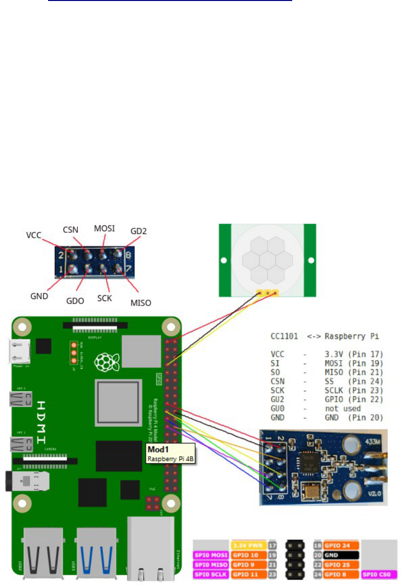
The boards attach to the SPI pins on the Pi:

You can attach the CC1101 board to the Pi using regular female to female breadboard cables, or you
can use a PCB adapter, like this:
Our eBay store has the PCB adapters ready assembled here:
https://www.ebay.co.uk/itm/135176300449
Or a PCB panel with 6 adapter PCBs on it, ready to make you own, here:
https://www.ebay.co.uk/itm/135176304156
We also have the correct blue PCB CC1101 modules for the adapters here:
https://www.ebay.co.uk/itm/166899335741
We even sell an adapter for the Flipper Zero, so you can plug a CC1101 external radio in:
https://www.ebay.co.uk/itm/135174202494
When the adapter is attached to the Pi you should be able to see 8 free pins either side of it.

As the adapter communicates over SPI, we need to enable SPI mode on the Raspberry Pi:
sudo raspi-config
We also need the WiringPi library installed.
wget https://github.com/WiringPi/WiringPi/releases/download/3.6/wiringpi_3.6_armhf.deb
sudo dpkg -i wiringpi_3.6_armhf.deb
If you have 64 bit Pi OS use wiringpi_3.6_arm64.deb instead.
Then do this:
gpio -v
gpio readall
Now we have SPI mode enabled and have WiringPi installed, we still need some software to drive
the CC1101 boards.

The best software to use can be found at this Github page: https://github.com/SpaceTeddy/CC1101
The readme file at the Github page covers basic installation and testing of the RX_Demo (receiver)
and TX_Demo (transmitter) scripts. This is exactly how we installed and configured it on both
machines:
sudo apt-get install git-core
git clone https://github.com/SpaceTeddy/CC1101
cd CC1101
cp ~/CC1101/examples/raspi/*.cpp ~/CC1101
Then on the machine that’s going to be the transmitter:
sudo g++ TX_Demo.cpp cc1100_raspi.cpp -o TX_Demo -lwiringPi
sudo chmod 755 TX_Demo
sudo ./TX_Demo -v -a1 -r3 -i1000 -t5 -c1 -f434 -m100
On the machine that will act as the receiver:
sudo g++ RX_Demo.cpp cc1100_raspi.cpp -o RX_Demo -lwiringPi
sudo chmod 755 RX_Demo
sudo ./RX_Demo -v -a3 -c1 -f434 -m100
If that worked you should now see packets going over-the-air between the two Pi’s, like this:
Note: I couldn’t get this to work correctly on a Pi5, where the Processor and GPIO pins are abstracted via a microcontroller, and
wiringPi support is still quite new (6
th
August 2024) – it locks up after seeming to transmit the first packet. It works fine on Pi4, Pi
Zero and even an original Model B running Raspberry Pi OS Lite Bookworm Debian 12.
Because the boards can work with a wide range of different frequencies, modulation schemes and
data rates, they are configured by sending a matching configuration block to each radio over SPI.
Once each radio is setup in the same configuration, it’s just a case of transmitting a data packet
burst on one radio and reading the receive buffer on the other radio.
The RX and TX demo files are great, but they don’t do anything really useful for us. In the next
examples I’ll show you how to attach a PIR to the transmitter Pi, and store times and dates the PIR
is triggered in a logfile on the receiver Pi.

You can download our own demos to both your Pi’s with:
wget securipi.co.uk/cc1101.zip
unzip cc1101.zip
ls
Here’s the list of files downloaded & what they do:
TX_DemoPir.cpp Transmits a PIR2 message whenever the PIR detects movement
RX_DemoPir.cpp Receives a signal and prints “PIR2 Triggered” to console.
RX_DemoPir2.cpp as above, with time and date logging to file test.txt
RX_DemoPir4.cpp as above, but also flashes an LED connected to GPIO4 when PIR triggered
Each of the cpp files are source code which needs to be compiled in the same way as the other
demos. So for example, to use TX_DemoPir.cpp
sudo g++ TX_DemoPir.cpp cc1100_raspi.cpp -o TX_DemoPir -lwiringPi
sudo chmod 755 TX_DemoPir
sudo ./TX_DemoPir -v -a1 -r3 -i1000 -t5 -c1 -f434 -m100
In the silent folder there’s another version of the receiver demo code, with all the printf statements
commented out and an exit(0) command immediately after it receives a valid code. We’ve done that
so you can call the receiver code from a shell script, and when a valid message is received by the
shell script you could send an email to your phone, or turn on an LED, or switch a relay controlling
a water pump, or open a door lock.
cd silent
ls
RX_DemoPir.cpp receiver with no message to screen, prints PIR2 and exits
receive.sh shell script, prints “PIR 2 triggered” to console. Loops
receive2.sh shell script, as above but doesn’t loop
receive3.sh as above, and turns on LED connected to GPIO4 for 3 seconds.
To use the silent versions of the receiver
sudo g++ RX_Demo.cpp cc1100_raspi.cpp -o RX_Demo -lwiringPi
sudo chmod 755 RX_Demo
chmod a+x receive3.sh
sudo ./receive3.sh
You can inspect & modify the contents of the source .cpp files and .sh files with nano. Example:
nano receive3.sh
You could use the TX_DemoPir program on several different Raspberry Pi’s, all with PIR modules
attached and just modify the message sent to PIR1, PIR2, or PIR3 on each different Pi. Then on the
receiver code, change this line, which currently looks for the number 2 → if( Rx_fifo[6] == 0x32)
to look for PIR1 with 0x31 or look for PIR3 with 0x33.

Attach a PIR sensor to the transmitter Pi. If you pull the white dome off the Pir sensor you’ll usually
see the pin designations screen-printed on the PCB. (radio shown is the old 5x2 pin version)
Pir sensor Raspberry Pi
VCC 5 Volts
GND GND
OUT GPIO 4 (pin 7 in WiringPi speak)
If you’re attaching an LED to the receiver, attach a 220 ohm resistor in series, like this:

In the previous pages we mentioned how the CC1101 radio gets configured - to work on a certain
frequency, modulation scheme and gain level - by a configuration block sent over the SPI interface.
When you run the standard TX_Demo and RX_Demo examples the current configuration settings
for Config Register and PaTable get printed to the terminal, like this:
If you edit the file cc1100_raspi.cpp you’ll see the config block for the -m100 modulation speed
option. The defaults are 868MHZ, and we’ve used 434MHz in the example above, so it got changed
around a bit:

Here’s the example of the PaTable settings (power output of the radio for each frequency)
You can see our PaTable setting matches the 433/434MHz setting from the command line
RX_Demo options.
Say you want to reverse engineer a wireless gadget of your own, and you’ve already descovered the
frequency, modulation scheme and data rate, how do you then find out the correct config values for
the radio? You need a free Windows application from Texas Instruments called Smart RF Studio 7.
You can download it from http://www.ti.com/tool/download/SMARTRFTM-STUDIO/
Then click the CC1101 button’s red circle and choose Open RF Device in Offline Mode.

The main screen for Smart RF Studio 7 looks like this:
In the center panel you can choose RF Parameters: Base Frequency, Modulation Format, Data Rate
and TX Power. When you change these values, the hex values on the right of the screen change too.
When all the options are set you can export the Hex values needed to configure the radio by
clicking the Register Export button on the top right of the window.

I’ve chosen template RF settings, then clicked on Select in the Registers tab, moved all 61 values to
the right hand pane, and then scrolled down to TEST0, selected everything below that starting with
PARTNUM, and moved them back to the left pane. I’m then left with a block of 47 values that can
be cut and pasted back into SpaceTeddy’s cc1100_raspi.cpp file, as replacements.
That only leaves us with the question of how do you discover that frequency, modulation scheme
and data rate of your current RF devices, that you might want to make the CC1101 module receive
from, or replicate the transmission signal of another device.
Say I have a wireless alarm system in my home that I know operates around the 868MHz band. I’d
first get a USB RTL-SDR/TV dongle for around £10-£20 from eBay (search on eBay for RTL-
SDR) and then install GQRX on my Ubuntu Linux PC following this short guide:
http://gqrx.dk/download/install-ubuntu You also need to blacklist the kernel driver otherwise it
assumes you want to use it as a TV stick – see http://oh2bsc.com/2015/02/17/getting-started-with-
sdr-radio-using-dvb-t-usb-dongle-and-gqrx/
GQRX is then installed to the Internet folder on my list of Programs.
In the picture above I’ve set the frequency to 868 MHz and clicked the play button in the top left. A
waterfall display then scrolls down the screen and when any RF gadget transmits it appears in the
waterfall. I pressed the keyfob for my car, and two red & yellow bursts appeared. Often 868MHz
gadgets operate on FSK, and because two bursts appear at the same time, I’m assuming the
modulation scheme is 2-FSK (supported by CC1101). We could export this sample to Audacity or
InSpectrum to work out the data rate or we could use Universal Radio Hacker.

Universal Radio Hacker is a set of tools for capturing and analysing RF signals from an RTL-SDR
USB dongle. Assuming you’ve tried GQRX, URH will run fine too.
https://github.com/jopohl/urh
The manual is here: https://github.com/jopohl/urh/raw/master/data/userguide.pdf
And the excellent YouTube tutorial videos start here: https://www.youtube.com/watch?
v=kuubkTDAxwA
I chose to run without installation, like this:
git clone https://github.com/jopohl/urh/
cd urh/src/urh
./main.py
If you want to do long range communications of say 1KM using two CC1101 modules, then you’ll
need a pair of decent Yagi antennas and free space between the two sites. The antennas are £30 each
from Farnell : http://uk.farnell.com/lprs/yagi-434a/antenna-yagi-7-element-434mhz/dp/2096215 or
http://uk.farnell.com/lprs/yagi-869a/antenna-yagi-9-element-869-915mhz/dp/2096216
If you liked this PDF please follow @securipi on twitter.
Check out our website www.securipi.co.uk
We sell lots of electronic parts and kits for Raspberry Pi and Arduino in our eBay shop:
http://stores.ebay.co.uk/ConvertStuffUK
and also here:
https://tri.co.uk/
If you spot any typos/issues please email [email protected] – last updated 5
th
August 2024.
