
Indian Journal of Science and Technology, Vol 8(23), DOI: 10.17485/ijst/2015/v8i23/79973, September 2015
ISSN (Print) : 0974-6846
ISSN (Online) : 0974-5645
* Author for correspondence
1. Introduction
All human beings, animals and plants need water for
survival. It is one of the basic needs for everyone. Most
of the agriculture systems face water wastage as the
major problem. Today agriculture uses 85% of water
for irrigation purposes only. In Irrigation the water
management plays an eective role. e agricultural
elds are aected by over and under irrigation due to
insuciency of water and rainfalls. is eect may
increase due to increase in population growth and food
demands. Water shortage is one of the major problems
in present day scenario
1
. Optical and IR images of plants
bring in few plant monitoring systems to the market
2
.
Water conservation using several methods reduced the
use of these plants monitoring systems
3
. ere are many
techniques for controlling water wastage. Ditch irrigation
scheme is the rst among them in which digging ditches
and planting seeds is done uniformly
4
. ere are certain
siphon tubes which use the movement from main ditch to
the canals. Drip irrigation is one of the vital methods for
irrigation in which water drops at the root zone of plant
5
.
Sprinkler system is an irrigation based system which uses
sprinklers, sprays or guns on the tubes. e water ows
through the tubes and at some ends where sprinklers are
present which sprinkle the water in such areas. Sprinklers
are activated based on the sensors for temperature and
humidity which go beyond the threshold value and are
present at the roots. Rotary systems are the best suited
for larger areas. Mechanically driven sprinklers are
connected to these rotor systems so that the water can
reach over a 100 feet radius. So, sprinklers are used to
reduce the amount of water needed as they cover large
radius. By using infrared thermometers remote canopy
Abstract
Background/Objectives: Indian agriculture is dependent on the monsoons which is not a reliable source of water, so there
is a need for an automatic irrigation system in the country which can provide water to the farms according to their moisture
and soil types. Methods/Statistical Analysis: The objective of this paper is to develop a low cost power effective sensor
based automatic irrigation system which is integrated to the microcontroller unit. The sensors used in this paper are soil
temperature sensor and humidity sensor SHT1X. These sensors are interfaced to the Wireless Sensing Unit (WSU) and the
entire unit was placed under the soil. It will transmit the sensor value to Wireless Interface Unit (WIU). The main motive
of using WIU is to receive the sensed value from WSU and to activate the solenoid valve as well as to send a message to the
mobile and also sends an email to the account of the user located in the remote area if the received value is greater than
the threshold. The SMS and email are sent using GPRS module interfaced with the wireless interface unit. Findings: The
irrigation system is tested under various temperatures and different levels of humidity for several plants in all conditions.
The soil moisture sensor limits the water content in a particular area. Conclusions: The throughput obtained in wet and
normal conditions are proved to be intuitive. Developing country like India sending SMS and email to authorize person is
understandable.
Keywords: Arduino, Raspberry pi, SHT10 Sensor, SIM900A, Solar Panel, Solenoid Valve, Zig-Bee Modules
Low Power Cost Eective Automatic
Irrigation System
Sandeep Nallani
*
and V. Berlin Hency
School of Electronics Engineering, VIT University, Chennai - 632014, Tamil Nadu, India;
Vol 8 (23) | September 2015 | www.indjst.org
Indian Journal of Science and Technology
2
Low Power Cost Effective Automatic Irrigation System
temperatures can be known and this helps us to automate
the cotton irrigation system
6
. A threshold temperature
is taken as a reference to compare with the monitored
canopy temperatures and based on that comparative
result the system triggers. To obtain the optimal results in
cotton yielding process and in eective utilization of aqua
resources the entire eld is automated instead of manual
monitoring. A WSN based wireless network has been used
which operates in European ISM UHF band to collect the
data to a single processing point to validate the biological
models in viticulture applications
7
, the main drawback of
this model is that the used UHF range is less compared
to Zig-bee. ere is an alternative parameter called Plant
Evapo Transpiration (ET), used to estimate the crop
irrigation needs. e combination of two terms such as
evaporation and plant transpiration gives the information
about the whole process. e process of vaporization
of water to air from soil, canopy
8
is called Evaporation.
e process of vaporization of water from leaves, stems
and owers is called Plant Transpiration. e system
which considers ET as a parameter will allow the water
savings up to 42%
9
. In recent years WSN nodes became
more popular because of applications such as in vehicle
monitoring and to control the robots. Measurement of
the soil moisture content is done in the paddy elds by
using TINY OS based IRIS nodes
10
.
ere are several solutions to measure the data
in the irrigation eld; the most popular one is Zig-
bee transmission of data from end devices. But using
these devices the distance between the two nodes are
limited between 10 to 100 meters only. So most of the
applications uses GPRS based systems to transmit the
data to the remote area
11
. e Zig-bee based transmission
is used in the agricultural eld in order to collect data
from dierent sensor nodes. Now a day’s wireless sensor
networks play an important role in food industry and
also in agriculture. e examples of such systems are
continuous environment monitoring system and to
maintain precision in agriculture RFID based traceability
systems
12
. e SIM900A is a GSM/GPRS based wireless
modem. e automated irrigation system plays an
important role in communication of the temperature,
humidity and the soil moisture content values which are
sensed from the sensor and send to the remote area
13
. is
can be done by using the AT commands. e GSM/GPRS
modem is interfaced to the microcontroller unit. For
remote monitoring, GPRS based systems are employed on
wireless sensor networks for monitoring the temperature
and humidity data continuously or periodically
14
. e
transmission of the sensors data which is under the root
zone of plant to the remote person is done using GSM/
GPRS modem
15
. e automatic irrigation system using
PIC microcontroller is not cost eective and it consumes
more power
16
.
2. System Architecture
2.1 Flow Chart
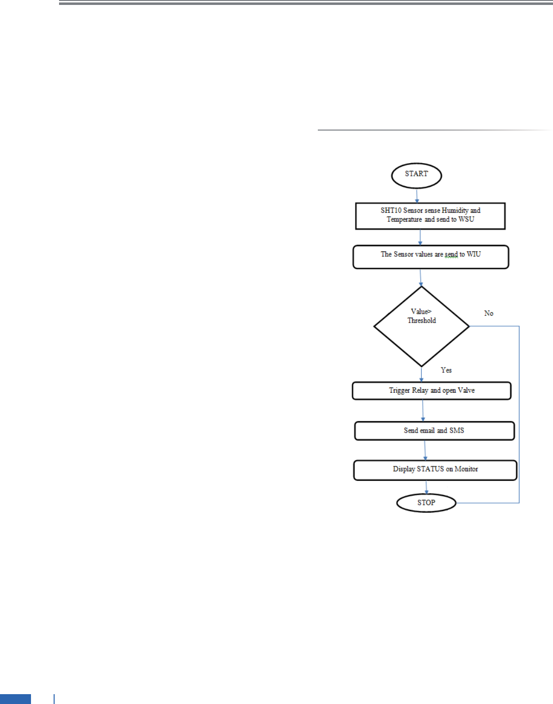
Figure 1. Flow Chart.
e ow chart of the proposed algorithm is shown in
Figure 1. e wireless sensing unit is connected to solar
panel of 12V. It is used to power up the sensor which is
placed under the soil and it is connected to WSU. e
SHT1X soil moisture sensor gives the soil temperature and
humidity at particular area in eld and sends the obtained
parametric values to control unit for every 5 minutes.
e Zig-bee end device is connected to Arduino receiver
and transmitter pin. e control unit receives the data of

Sandeep Nallani and V. Berlin Hency
Vol 8 (23) | September 2015 | www.indjst.org
Indian Journal of Science and Technology
3
the sensors sent by the sensor unit through Zig-bee are
compared with the predened threshold value which is
programmed in the control unit. When the received data
value is greater than the threshold value then the control
unit activates the solenoidal valve by triggering the relay.
e status of valve is sent to the authorized person through
Gmail and SMS connected through GPRS. Whenever the
received data value is less than the threshold value then
the control unit will display the status of solenoidal valve
on display screen.
2.2 Block Diagram
e Block diagram implementation of an automated
irrigation system is shown in Figure 2. e automated
irrigation system consists of two units one is wireless
sensing unit and the other is wireless interface unit.
e wireless interface unit consists of Raspberry pi. e
solenoidal valve, Zig-bee receiver, GPRS is connected to
raspberry pi. e wireless sensing unit consists of SHT1X
sensor and Zig-bee transmitter.
Figure 2. Block diagram.
3. Design Implementation
e solar panel is connected to Wireless sensing unit.
By using IC7805 it supply constant 5V to Arduino. e
wireless sensing unit is used to measure soil humidity
and temperature. e sensor is placed under the soil
at a depth of 8cm. e depth of placing sensor varies.
It depends upon type of soil and crop. e amount of
water required for crop depends upon soil. ere are two
dierent types of soil one is black soil and another is red
soil. Each gas molecules have a dielectric constant. When
a senor is placed under the soil the change in dielectric in
capacitor based sensor and change in temperature leads
to excite the electrons from ionic bond to valence bond
in band gap sensor gives the rise and fall of humidity
and temperature readings. e sensor is powered up by
supplying 5V. e data pin and clock pin is connected to
Arduino. e clock pin is activated from low to high and
data pin is activated from high to low. e sensor sends
signal to Arduino by activating data pin from high to
low. e sensor read humidity by sending a command
(0b00000101). e SHT10 sends one byte to Arduino and
receives acknowledgement. e sensors send second byte
to Arduino and omits acknowledgement to skip cyclic
redundancy check. By using equation (1) and equation (2)
conversion of humidity value from bit to decimal value is
carried out. By using equation (3) converting temperature
value from bit to decimal is carried out. e rst byte and
second byte which are received from the sensor are used to
form humidity value and temperature value by using Table
1 and Table 2. To get temperature value the sensors send
command (0b000001101).
RH
linear
= c
1
+ c
2
.SO
RH
+ c
3
.SO
2
RH
(%RH) (1)
RH
linear
= c
1
+ c
2
.SO
RH
+ c
3
.SO
2
RH
(%RH) (2)
Table 1. Humidity coecient
SO
T
c
1
c
2
c
3
12 bit -2.046 0.0367 -1.5955E-6
8 bit -2.0468 0.5872 -4.0845E-4
Table 2. Temperature coecient
SO
T
d
2
(ºC) d
2
(ºF)
14-bit 0.01 0.018
12-bit 0.04 0.072
e Arduino reads the values and send the value to WIU
using Zig-bee end device which is connected to receiver
and transmitter pin of Arduino. e Arduino supplies
power to Zig-bee. e WIU use the microcontroller
BCM 2385 is arm11 processer which is built in raspberry
pi. e Zig-bee coordinator, GPRS and solenoid valve is
connected to raspberry pi. e Coordinator transmitter
and receiver pin is connected to raspberry pi UART pins.
e solenoid pin is connected to relay Normal Close mode

Vol 8 (23) | September 2015 | www.indjst.org
Indian Journal of Science and Technology
4
Low Power Cost Effective Automatic Irrigation System
(NC) and relay is connected to raspberry pi. If the received
value is greater than pre-dened threshold valve it will
activate the solenoidal valve using relay where relay acts as
a switch. e solenoid valve requires 12V of power and to
pump water it requires minimum 0.02Mpa to maximum
0.08Mpa pressure. e GPRS sim900 module is connected
to raspberry pi. It required 5V to power up and operate at
a baud rate of 9600 through serial port. e valve pumps
the water when it exceeds threshold value. Once if it
reaches below threshold value the valve will close. Using
GPRS the status of valve is send to mail using Simple Mail
Transfer Protocol (SMTP) and status also send to mobile
number using Uniform Resource Locator (URL). If the
sensor value is less than the threshold value then it will be
displayed on the screen.
4. Results
Figure 3. WSU hardware.
Figure 4. WIU hardware.
Environmental parameters play an important role in
irrigation system. e water requirement during summer
or winter season is dierent.
Figure 5. Status display in screen.
Figure 6. SMS text received.
e wireless sensing unit is shown in Figure 3. e
sensor is placed under the soil at a depth of 8cm. Dierent
values of temperature and humidity reading is noted.
Most of the values are fallen between 29
º
C - 38
º
C. If soil
moisture is less than threshold value then the plant is

Sandeep Nallani and V. Berlin Hency
Vol 8 (2 3) | S ept ember 2 01 5 | w ww. indj st.org
Indian Journal of Science and Technology
5
considered to be in unsafe state. e wireless interface is
shown in Figure 4. e unit receives values from WSU
and compared it with the predened threshold value. If
it exceeds the threshold value then the relay will trip and
LED glows, the valve will open and status of relay will be
displayed on the screen as shown in Figure 5. e valve
pumps water. e interface unit send SMS and emails text
to the owner. e SMS received is shown in Figure 6 and
mail received is shown in Figure 9.
By using Simple Mail Transfer Protocol (SMTP) pre-
dened message mail is sent to user. e SMTP server
will send an email to receiver’s email address. To send
a message, SMTP protocol has to interconnect with
domain name server takes the recipient’s email address
and translate it into an IP address. e receiver SMTP
server examines the incoming message. If it recognizes
the domain and the username, it forwards the message to
domain POP3. From there it is placed in a mail queue. At
that point, the message can be read by receiver.
It is understood from Figure 7 that the temperature
varies from the mornin g to evening. Figure 7 is plotted
from Table 3.
Figure 7. Gmail text received.
As the plant grows water consumption increases from
day by day once the growth reaches particular level plant
does not need so much of water. So, the threshold values
also changes accordingly which is shown in Figure 8. e
threshold can be set according to the values obtained
under dierent conditions. e threshold values chosen
are in the range of 29
º
C - 38
º
C. e threshold may vary
from place to place because it may not be constant in every
region. e low power cost eective automatic irrigation
system will be helpful for farmers.
Table 3. Humidity and Temperature readings
RH% C(AIR) F(AIR) C(WET) F(WET)
20 30 86 16 61
35 30 86 19 66
35 35 95 23 73
65 35 95 29 84
80 35 95 32 90
Figure 8. Temp er atu re vs. Tim e.
Figure 9. Humidity vs. Date.
5. Conclusion
e automated irrigation system was implemented using
the WIU and WSU. e sensor values are transmitted
from WSU to WIU through wireless media. e interface
unit checks the threshold value and if it exceeds the
predene value then the status of valve is send to the user.
e dierent values for the SHT10 sensor is measured
under dierent climatic conditions and the threshold

Vol 8 (23) | September 2015 | www.indjst.org
Indian Journal of Science and Technology
6
Low Power Cost Effective Automatic Irrigation System
values are set based on those practical values. is system
can be extended by using data base to store the data at the
eld and the camera to monitor the growth of plant. e
overall system is powered up by using renewable energy.
6. References
1. Jury WA, Vaux HJ. e emerging global water crisis:
Managing scarcity and conict between water users. Adv
Agronomy. 2007 Sep; 95:1–76.
2. Wang X, Yang W, Wheaton A, Cooley N, Moran B. E-
cient registration of optical and IR images for automatic
plant water stress assessment. Comput Electron Agr. 2010;
74(2):230–7.
3. Yuan G, Luo Y, Sun X, Tang D. Evaluation of a crop water
stress index for detecting water stress in winter wheat in the
North China Plain. Agr Water Manag. 2004 Jan; 64:29–40.
4. Idso SB, Jackson RD, Pinter PJ, Reginato RJ Jr, Hateld JL.
Normalizing the stress-degree-day parameter for environ-
mental variability. Agr Mateorol. 1981 Jan; 24:45–55.
5. Erdem Y, Arin L, Erdem T, Polat S, Deveci M, Okursoy H,
Gultas HT. Crop water stress index for assessing irrigation
scheduling of drip irrigated broccoli (Brassica oleracea L.
var. Italic). Agr Water Manag. 2010 Dec; 98(1):148–56.
6. Nemali KS, Van Iersel MW. An automated system for con-
trolling drought stress and irrigation in potted plant. Scien-
tia Horticulture. 2006 Nov; 110(3):292–7.
7. O’Shaughnessy SA, Evett SR. Canopy temperature based
system eectively schedules and controls centre pivot irri-
gation of cotton. IEEE Transaction on Agricultural Water
Management. 2010 April; 97(9):1310–6.
8. Allen RG, Pereira LS, Raes D, Smith M. Crop evapotrans-
piration-guidelines for computing crop water requirements
- FAO irrigation and drainage paper. 1998; 56:148–56.
9. Dursun M, Ozden S. A wireless application of drip irriga-
tion automation supported by soil moisture sensors. Sci Res
Essays. 2011; 6(7):1573–82.
10. Alagapudi P, Ramesh R, Gayatri S. Smart irrigation system
for outdoor environment using tiny OS. Computation of
Power, Energy, Information and Communication. 2014
April 17. p. 104–8.
11. Zhou Y, Yang X, Wang L, Ying Y. A wireless design of low-
cost irrigation system using Zig-bee technology. Interna-
tional Conference on Network Security, Wireless Commu-
nications and Trusted Computing. 2009; 1:572–5.
12. Wang N, Zhang N, Wang M. Wireless sensors in Agri-
culture and Food Industry. Comput Electron Agr. 2005;
50(1):1–14.
13. Dursun M, Ozden S. A wireless application of drip irriga-
tion automation supported by soil moisture sensors. Sci Res
Essays. 2011; 6(7):1573–82.
14. Liu H, Wang M-H, Wang Y-X, Ma D-K, Li H-X. Develop-
ment of farm land soil moisture and temperature monitor-
ing system based on wireless sensor networks. Journal of
Jilin University, Engineering and Technology. 2008; 38(3).
15. Balendonck J, Hemming J. Sensors and wireless sensor net-
works for irrigation management under deceit conditions.
International Conference on Agricultural Engineering.
2008.
16. Gutierrez J, Villa-Medina JF, Nieto-Garibay A, Porta-Gan-
dara MA. Automatic irrigation system using wireless sen-
sor network and GPRS. IEEE Transaction on Instrumenta-
tion and Measurement. 2014 Jan; 63(1):166–76.r
