
XClarity Controller with Intel Xeon SP (1st, 2nd
Gen)
User's Guide
Note: Before using this information, read the general information in Appendix B “Notices” on page 203.
Fifteenth Edition (May 2021)
© Copyright Lenovo 2017, 2022.
LIMITED AND RESTRICTED RIGHTS NOTICE: If data or software is delivered pursuant to a General Services
Administration (GSA) contract, use, reproduction, or disclosure is subject to restrictions set forth in Contract No.
GS-35F-05925.

Contents
Contents . . . . . . . . . . . . . . . . . i
Chapter 1. Introduction . . . . . . . . . 1
XClarity Controller Standard, Advanced, and
Enterprise Level features . . . . . . . . . . . . 2
XClarity Controller Standard Level features . . . 2
XClarity Controller Advanced Level features . . . 5
XClarity Controller Enterprise Level features . . . 5
Upgrading XClarity Controller . . . . . . . . 6
Web browser and operating-system
requirements . . . . . . . . . . . . . . . . . 6
Multiple language support. . . . . . . . . . . . 7
MIBs Introduction . . . . . . . . . . . . . . . 7
Notices used in this document . . . . . . . . . . 8
Chapter 2. Opening and Using the
XClarity Controller Web Interface . . . . 9
Accessing the XClarity Controller web interface . . . 9
Setting up the XClarity Controller network
connection through the XClarity Provisioning
Manager . . . . . . . . . . . . . . . . 10
Logging in to the XClarity Controller . . . . . 12
Description of XClarity Controller functions on web
interface. . . . . . . . . . . . . . . . . . 13
Chapter 3. Configuring the XClarity
Controller . . . . . . . . . . . . . . . 17
Configuring user accounts/LDAP . . . . . . . . 17
User authentication method . . . . . . . . 17
Creating a new user account . . . . . . . . 18
Deleting a user account . . . . . . . . . . 20
Using hashed passwords for authentication . . 20
Configuring global login settings . . . . . . 22
Configuring LDAP . . . . . . . . . . . . 24
Configuring network protocols . . . . . . . . . 29
Configuring the Ethernet settings . . . . . . 29
Configuring DNS . . . . . . . . . . . . 31
Configuring DDNS . . . . . . . . . . . . 31
Configuring Ethernet over USB . . . . . . . 32
Configuring SNMP . . . . . . . . . . . . 32
Enabling or Disabling IPMI Network Access . . 33
Configuring Network Settings with IPMI
commands . . . . . . . . . . . . . . . 33
Service Enablement and Port Assignment. . . 33
Configuring Access Restriction . . . . . . . 34
Configuring Front Panel USB Port to
Management . . . . . . . . . . . . . . 35
Configuring security settings. . . . . . . . . . 36
SSL overview . . . . . . . . . . . . . . 36
SSL certificate handling . . . . . . . . . . 37
SSL certificate management . . . . . . . . 37
Configuring the Secure Shell server . . . . . 38
IPMI over Keyboard Controller Style (KCS)
Access . . . . . . . . . . . . . . . . 38
Prevent System Firmware Down-Level . . . . 39
Assert Physical Presence . . . . . . . . . 39
Configuring the Security Key Management
(SKM) . . . . . . . . . . . . . . . . . 39
Extended Audit Log . . . . . . . . . . . 43
Cryptography Setting. . . . . . . . . . . 43
Backing up and Restoring the BMC
configuration . . . . . . . . . . . . . . . . 45
Backing up the BMC configuration . . . . . 45
Restoring the BMC configuration . . . . . . 46
Resetting the BMC to Factory Default . . . . 46
Restarting the XClarity Controller . . . . . . . . 46
Chapter 4. Monitoring the server
status. . . . . . . . . . . . . . . . . . 47
Viewing the Health Summary/Active System
Events . . . . . . . . . . . . . . . . . . 47
Viewing the System Information . . . . . . . . 48
Viewing the System Utilization . . . . . . . . . 50
Viewing Event Logs . . . . . . . . . . . . . 51
Viewing Audit Logs . . . . . . . . . . . . . 51
Viewing the Maintenance History . . . . . . . . 52
Configuring Alert Recipients . . . . . . . . . . 52
Capturing the latest OS failure screen data . . . . 54
Chapter 5. Configuring the Server . . 55
Viewing the adapter information and configuration
settings . . . . . . . . . . . . . . . . . . 55
Configuring system boot mode and order. . . . . 55
Configuring one-time boot . . . . . . . . . . 56
Managing the server power . . . . . . . . . . 57
Configuring the power redundancy . . . . . 57
Configuring the power capping policy . . . . 57
Configuring the power restore policy . . . . . 58
Power actions. . . . . . . . . . . . . . 58
Managing and monitoring power consumption
with IPMI commands . . . . . . . . . . . 59
Remote Console Functionality . . . . . . . . . 61
Enabling the remote console functionality . . . 62
Remote power control . . . . . . . . . . 62
Remote console capture screen . . . . . . 63
Remote console keyboard support . . . . . 63
© Copyright Lenovo 2017, 2022 i
Remote console mouse support . . . . . . 64
Screen Video Record/Replay . . . . . . . . 64
Remote console screen modes . . . . . . . 65
Media mount methods . . . . . . . . . . 65
Remote disk using Java client . . . . . . . 69
Media mount error issues . . . . . . . . . 73
Exiting the remote console session . . . . . 75
Downloading service data . . . . . . . . . . . 75
Server Properties . . . . . . . . . . . . . . 75
Setting Location and Contact . . . . . . . 75
Setting server timeouts . . . . . . . . . . 76
Trespass message . . . . . . . . . . . . 76
Setting the XClarity Controller date and time . . . 77
Chapter 6. Configuring the
Storage. . . . . . . . . . . . . . . . . 79
RAID Detail . . . . . . . . . . . . . . . . 79
RAID Setup . . . . . . . . . . . . . . . . 79
Viewing and configuring the virtual drives . . . 79
Viewing and configuring the storage
inventory. . . . . . . . . . . . . . . . 80
Chapter 7. Updating Server
Firmware . . . . . . . . . . . . . . . . 83
Overview . . . . . . . . . . . . . . . . . 83
System, Adapter and PSU Firmware Update . . . 83
Chapter 8. License Management . . . 85
Installing an activation key. . . . . . . . . . . 85
Removing an activation key . . . . . . . . . . 86
Exporting an activation key . . . . . . . . . . 86
Chapter 9. Lenovo XClarity
Controller Redfish REST API . . . . . 87
Chapter 10. Command-line
interface . . . . . . . . . . . . . . . . 89
Accessing the command-line interface . . . . . . 89
Logging in to the command-line session . . . . . 89
Configuring serial-to-SSH redirection . . . . . . 89
Command syntax . . . . . . . . . . . . . . 90
Features and limitations . . . . . . . . . . . 90
Alphabetical command listing . . . . . . . . . 91
Utility commands . . . . . . . . . . . . . . 93
exit command. . . . . . . . . . . . . . 93
help command . . . . . . . . . . . . . 93
history command . . . . . . . . . . . . 93
Monitor commands . . . . . . . . . . . . . 94
clearlog command . . . . . . . . . . . . 94
fans command . . . . . . . . . . . . . 95
ffdc command . . . . . . . . . . . . . 95
hreport command . . . . . . . . . . . . 96
mhlog command . . . . . . . . . . . . 97
led command . . . . . . . . . . . . . . 97
readlog command . . . . . . . . . . . . 99
syshealth command . . . . . . . . . . . 100
temps command . . . . . . . . . . . . 101
volts command . . . . . . . . . . . . . 101
vpd command . . . . . . . . . . . . . 102
Server power and restart control commands . . . 102
power command . . . . . . . . . . . . 102
reset command . . . . . . . . . . . . . 104
fuelg command . . . . . . . . . . . . . 105
pxeboot command. . . . . . . . . . . . 106
Serial redirect command . . . . . . . . . . . 107
console command . . . . . . . . . . . . 107
Configuration commands . . . . . . . . . . . 107
accseccfg command . . . . . . . . . . . 107
alertcfg command . . . . . . . . . . . . 108
asu command. . . . . . . . . . . . . . 109
backup command . . . . . . . . . . . . 112
dhcpinfo command . . . . . . . . . . . 113
dns command . . . . . . . . . . . . . 114
encaps command . . . . . . . . . . . . 116
ethtousb command . . . . . . . . . . . 116
firewall command . . . . . . . . . . . . 117
gprofile command . . . . . . . . . . . . 118
hashpw command . . . . . . . . . . . . 118
ifconfig command . . . . . . . . . . . . 119
keycfg command . . . . . . . . . . . . 122
ldap command . . . . . . . . . . . . . 123
ntp command. . . . . . . . . . . . . . 125
portcfg command . . . . . . . . . . . . 126
portcontrol command. . . . . . . . . . . 127
ports command . . . . . . . . . . . . . 128
rdmount command. . . . . . . . . . . . 129
restore command . . . . . . . . . . . . 130
restoredefaults command . . . . . . . . . 130
roles command . . . . . . . . . . . . . 131
seccfg command . . . . . . . . . . . . 132
set command . . . . . . . . . . . . . . 132
smtp command . . . . . . . . . . . . . 133
snmp command . . . . . . . . . . . . . 133
snmpalerts command . . . . . . . . . . 135
srcfg command . . . . . . . . . . . . . 137
sshcfg command . . . . . . . . . . . . 138
ssl command . . . . . . . . . . . . . . 139
sslcfg command. . . . . . . . . . . . . 140
storekeycfg command . . . . . . . . . . 143
syncrep command . . . . . . . . . . . . 144
thermal command . . . . . . . . . . . . 145
ii XClarity Controller with Intel Xeon SP (1st, 2nd Gen)User's Guide

timeouts command . . . . . . . . . . . 146
tls command . . . . . . . . . . . . . . 147
trespass command. . . . . . . . . . . . 147
uefipw command . . . . . . . . . . . . 148
usbeth command . . . . . . . . . . . . 149
usbfp command. . . . . . . . . . . . . 149
users command . . . . . . . . . . . . . 149
IMM control commands . . . . . . . . . . . 154
alertentries command . . . . . . . . . . 154
batch command. . . . . . . . . . . . . 156
clearcfg command . . . . . . . . . . . . 157
clock command . . . . . . . . . . . . . 157
identify command . . . . . . . . . . . . 158
info command . . . . . . . . . . . . . 158
spreset command . . . . . . . . . . . . 159
Agent-less commands . . . . . . . . . . . . 159
storage command . . . . . . . . . . . . 159
adapter command . . . . . . . . . . . . 168
m2raid command . . . . . . . . . . . . 170
Support commands . . . . . . . . . . . . . 171
dbgshimm command . . . . . . . . . . . 171
Chapter 11. IPMI interface . . . . . . 173
Managing the XClarity Controller with IPMI . . . . 173
Using IPMItool . . . . . . . . . . . . . . . 173
IPMI Commands with OEM Parameters . . . . . 174
Get / Set LAN Configuration Parameters . . . 174
OEM IPMI Commands . . . . . . . . . . 185
Chapter 12. Edge servers . . . . . . . 195
System Lockdown Mode . . . . . . . . . . . 195
SED Authentication Key (AK) Manager . . . . . . 196
Edge Networking . . . . . . . . . . . . . . 196
Appendix A. Getting help and
technical assistance . . . . . . . . . . 199
Before you call . . . . . . . . . . . . . . . 199
Collecting service data . . . . . . . . . . . . 200
Contacting Support . . . . . . . . . . . . . 201
Appendix B. Notices. . . . . . . . . . 203
Trademarks . . . . . . . . . . . . . . . . 204
Important notes . . . . . . . . . . . . . . . 204
Particulate contamination . . . . . . . . . . . 204
Telecommunication regulatory statement. . . . . 205
Electronic emission notices . . . . . . . . . . 205
Taiwan BSMI RoHS declaration . . . . . . . 206
Taiwan import and export contact information . . . 206
Index . . . . . . . . . . . . . . . . . . 209
© Copyright Lenovo 2017, 2022 iii
iv XClarity Controller with Intel Xeon SP (1st, 2nd Gen)User's Guide

Chapter 1. Introduction
The Lenovo XClarity Controller (XCC) is the next generation management controller that replaces the
baseboard management controller (BMC) for Lenovo ThinkSystem servers.
It is the follow-on to the Integrated Management Module II (IMM2) service processor that consolidates the
service processor functionality, Super I/O, video controller, and remote presence capabilities into a single
chip on the server system board. It provides features such as the following:
• Choice of a dedicated or shared Ethernet connection for systems management
• Support for HTML5
• Support for access via XClarity Mobile
• XClarity Provisioning Manager
• Remote configuration using XClarity Essentials or XClarity Controller CLI.
• Capability for applications and tools to access the XClarity Controller either locally or remotely
• Enhanced remote-presence capabilities.
• REST API (Redfish schema) support for additional web-related services and software applications.
Note: The XClarity Controller currently supports Redfish Scalable Platforms Management API
Specification 1.15.0 and schema 2021.4
Notes:
• In the XClarity Controller web interface, BMC is used in referring to the XCC.
• A dedicated systems-management network port may not be available on some ThinkSystem servers; for
these servers access to the XClarity Controller is only available through a network port that is shared with
the server operating system.
• For Flex servers, the Chassis Management Module (CMM) is the primary management module for
systems-management functions. Access to the XClarity Controller is available through the network port on
the CMM.
This document explains how to use the functions of the XClarity Controller in a ThinkSystem server. The
XClarity Controller works with the XClarity Provisioning Manager and UEFI to provide systems-management
capability for ThinkSystem servers.
To check for firmware updates, complete the following steps.
Note: The first time you access the Support Portal, you must choose the product category, product family,
and model numbers for your server. The next time you access the Support Portal, the products you selected
initially are preloaded by the website, and only the links for your products are displayed. To change or add to
your product list, click the Manage my product lists link. Changes are made periodically to the website.
Procedures for locating firmware and documentation might vary slightly from what is described in this
document.
1. Go to
http://datacentersupport.lenovo.com.
2. Under Support, select Data Center.
3. When the content is loaded, select Servers.
4. Under Select Series, first select the particular server hardware series, then under Select SubSeries,
select the particular server product subseries, and finally, under Select Machine Type select the
particular machine type.
© Copyright Lenovo 2017, 2022 1

XClarity Controller Standard, Advanced, and Enterprise Level features
With the XClarity Controller, Standard, Advanced, and Enterprise levels of XClarity Controller functionality are
offered. See the documentation for your server for more information about the level of XClarity Controller
installed in your server. All levels provide the following:
• Around-the-clock remote access and management of your server
• Remote management independent of the status of the managed server
• Remote control of hardware and operating systems
Note: Some features might not apply to Flex system servers.
The following is a list of XClarity Controller standard level features:
XClarity Controller Standard Level features
The following is a list of XClarity Controller Standard Level features:
Industry Standard Management Interfaces
• IPMI 2.0 Interface
• Redfish
• CIM-XML
• DCMI 1.5
• SNMPv3
• SNMPv1 ( Traps Only ) requires minimum v2.10 or v2.12 XCC Firmware updates depending on server
type. See XCC Firmware update Change file for details.
Other Management Interfaces
• Web
• Legacy CLI
• Front Panel USB - virtual operator panel via mobile device
Power / Reset Control
• Power On
• Hard/Soft Shutdown
• Scheduled Power Control
• System Reset
• Boot Order Control
Event Logs
• IPMI SEL
• Human Readable Log
• Audit Log
Environmental Monitoring
• Agent Free Monitoring
• Sensor Monitoring
2
XClarity Controller with Intel Xeon SP (1st, 2nd Gen)User's Guide
• Fan Control
• LED Control
• Chipset Errors (Caterr, IERR, etc...)
• System Health Indication
• OOB Performance Monitoring for I/O adapters
• Inventory Display and Export
RAS
• Virtual NMI
• Automatic Firmware Recovery
• Automated promotion of backup firmware
• POST Watchdog
• OS Loader Watchdog
• Blue Screen Capture (OS Failure)
• Embedded Diagnostic Tools
Network Configuration
• IPv4
• IPv6
• IP Address, Subnet Mask, Gateway
• IP Address Assignment Modes
• Host name
• Programmable MAC address
• Dual MAC Selection (if supported by server hardware)
• Network Port Reassignments
• VLAN Tagging
Network Protocols
• DHCP
• DNS
• DDNS
• HTTP/HTTPS
• SNMPv3
• SNMPv1 (Traps only)
• SSL
• SSH
• SMTP
• LDAP client
• NTP
• SLP
• SSDP
Chapter 1. Introduction 3
Alerts
• PET Traps
• CIM Indication
• SNMP TRAPs
• E-mail
• Redfish events
Serial Redirection
• IPMI SOL
• Serial port configuration
Security
• XClarity Controller Core Root of Trust for Measurement (CRTM)
• Digitally signed firmware updates
• Role Based Access Control (RBAC)
• Local User Accounts
• LDAP/AD User Accounts
• Secure Rollback of Firmware
• Chassis intrusion detection (only available on some server models)
• XCC remote assertion of UEFI TPM Physical Presence
• Audit logging of configuration changes and server actions
• Public-key (PK) Authentication
• System Retire/Repurpose
Remote Presence
• Remote Disk on Card (RDOC): Virtual Media mounting of remote ISO/IMG files via CIFS, NFS, HTTP,
HTTPS, FTP, SFTP, and LOCAL
Power Management
• Real time Power Meter
License Management
• Activation Key Validation and Repository
Deployment & Configuration
• Remote Configuration
• Deployment & Configuration Tools and Driver Packs using the embedded XClarity Provisioning Manager
• Configuration Backup and Restore
Firmware Updates
• Agent Free Update
• Remote Update
4
XClarity Controller with Intel Xeon SP (1st, 2nd Gen)User's Guide
XClarity Controller Advanced Level features
The following is a list of XClarity Controller Advanced Level features:
All of the XClarity Controller Standard Level features plus:
Alerts
• Syslog
Remote Presence
• Remote KVM
Serial Redirection
• Serial Redirection via SSH
Security
• Security Key Lifecycle Manager (SKLM)
• IP address blocking
Power Management
• Real time Power Graphics
• Historical Power Counters
• Temperature Graphics
Deployment & Configuration
• Remote OS Deployment using the embedded XClarity Provisioning Manager with the XClarity Controller
Remote KVM feature
XClarity Controller Enterprise Level features
The following is a list of XClarity Controller Enterprise Level features:
All of the XClarity Controller Standard and Advanced Level features plus:
RAS
• Boot Capture
Remote Presence
• Quality/Bandwidth Control
• Virtual Console Collaboration (six users)
• Virtual Console Chat
• Virtual Media
– Mounting of remote ISO/IMG files via remote console
– Mounting file from Network: - Mount an ISO or IMG image file from a file server ( HTTPS, CIFS, NFS ) to
the host as a DVD or USB drive
Power Management
• Power Capping
Chapter 1. Introduction 5

• OOB Performance Monitoring - System Performance metrics
Deployment & Configuration
• Remote Deployment using Lenovo XClarity Administrator. When using the Lenovo XClarity Administrator
for operating system deployment, see
https://pubs.lenovo.com/lxca/supported_operating_system_images
for details on the supported operating systems.
Upgrading XClarity Controller
If your server came with the Standard or Advanced level of the XClarity Controller firmware functionality, you
might be able to upgrade the XClarity Controller functionality in your server. For more information about
available upgrade levels and how to order, see
Chapter 8 “License Management” on page 85.
Web browser and operating-system requirements
Use the information in this topic to view the list of supported browsers, cipher suites and operating systems
for your server.
The XClarity Controller web interface requires one of the following web browsers:
• Chrome 64.0 or above (64.0 or above for Remote Console)
• Firefox ESR 78.0 or above
• Microsoft Edge 79.0 or above
• Safari 12.0 or above (iOS 7 or later and OS X)
Note: Support for the remote console feature is not available through the browser on mobile device
operating systems.
The browsers listed above match those currently supported by the XClarity Controller firmware. The XClarity
Controller firmware may be enhanced periodically to include support for other browsers.
Depending upon the version of the firmware in the XClarity Controller, web browser support can vary from
the browsers listed in this section. To see the list of supported browsers for the firmware that is currently on
the XClarity Controller, click the Supported Browsers menu list from the XClarity Controller login page.
For increased security, only high strength ciphers are now supported when using HTTPS. When using
HTTPS, the combination of your client operating system and browser must support one of the following
cipher suites:
• ECDHE-ECDSA-AES256-GCM-SHA384
• ECDHE-ECDSA-AES256-SHA384
• ECDHE-ECDSA-AES256-SHA
• ECDHE-ECDSA-AES128-GCM-SHA256
• ECDHE-ECDSA-AES128-SHA256
• ECDHE-ECDSA-AES128-SHA
• ECDHE-RSA-AES256-GCM-SHA384
• ECDHE-RSA-AES256-SHA384
• ECDHE-RSA-AES128-GCM-SHA256
• ECDHE-RSA-AES128-SHA256
6
XClarity Controller with Intel Xeon SP (1st, 2nd Gen)User's Guide

Your internet browser's cache stores information about web pages that you visit so that they will load more
quickly in the future. After a flash update of the XClarity Controller firmware, your browser may continue to
use information from its cache instead of retrieving it from the XClarity Controller. After updating the XClarity
Controller firmware, it is recommended that you clear the browser cache to ensure that web pages served by
the XClarity Controller are displayed correctly.
Multiple language support
Use the information in this topic to view the list of languages supported by the XClarity Controller.
By default, the chosen language for the XClarity Controller web interface is English. The interface is capable
of displaying multiple languages. These include the following:
• French
• German
• Italian
• Japanese
• Korean
• Portuguese (Brazil)
• Russian
• Simplified Chinese
• Spanish (international)
• Traditional Chinese
To choose the language of your preference, click the arrow beside the currently selected language. A drop-
down menu will appear to let you choose your preferred language.
Text strings that are generated by the XClarity Controller firmware are displayed in the language dictated by
the browser. If the browser specifies a language other than one of the translated languages listed above, the
text is displayed in English. In addition, any text string that is displayed by the XClarity Controller firmware,
but is not generated by the XClarity Controller (for example messages generated by UEFI, PCIe adapters,
etc…) are displayed in English.
The input of language-specific text other than English, such as the Trespass message is currently not
supported. Only text typed in English is supported.
MIBs Introduction
Use the information in this topic to access Management Information Base.
The SNMP MIBs can be downloaded from the
https://support.lenovo.com/ (Search by machine type on the
portal). It includes the following four MIBs.
• The SMI MIB describes the Structure of Management Information for the Lenovo Data Center Group.
• The Product MIB describes the object identifier for Lenovo Products.
• The XCC MIB provides the inventory and monitoring information for Lenovo XClarity Controller.
• The XCC Alert MIB defines traps for alert conditions detected by Lenovo XClarity Controller.
Note: The import order for the four MIBs is SMI MIB → Product MIB → XCC MIB → XCC Alert MIB.
Chapter 1. Introduction 7

Notices used in this document
Use this information to understand the notices that are used in this document.
The following notices are used in the documentation:
• Note: These notices provide important tips, guidance, or advice.
• Important: These notices provide information or advice that might help you avoid inconvenient or
problem situations.
• Attention: These notices indicate potential damage to programs, devices, or data. An attention notice is
placed just before the instruction or situation in which damage might occur.
8
XClarity Controller with Intel Xeon SP (1st, 2nd Gen)User's Guide

Chapter 2. Opening and Using the XClarity Controller Web
Interface
This topic describes the login procedures and the actions that you can perform from the XClarity Controller
web interface.
The XClarity Controller combines service processor functions, a video controller, and remote presence
function in a single chip. You must first log in using the XClarity Controller web interface to access the
XClarity Controller remotely. This chapter describes the login procedures and the actions that you can
perform from the XClarity Controller web interface.
Accessing the XClarity Controller web interface
The information in this topic explains how to access the XClarity Controller web interface.
The XClarity Controller supports static and Dynamic Host Configuration Protocol (DHCP) IPv4 addressing.
The default static IPv4 address assigned to the XClarity Controller is 192.168.70.125. The XClarity Controller
is initially configured to attempt to obtain an address from a DHCP server, and if it cannot, it uses the static
IPv4 address.
The XClarity Controller also supports IPv6, but it does not have a fixed static IPv6 IP address by default. For
initial access to the XClarity Controller in an IPv6 environment, you can either use the IPv4 IP address or the
IPv6 link-local address. The XClarity Controller generates a unique link-local IPv6 address, using the IEEE
802 MAC address by inserting two octets, with hexadecimal values of 0xFF and 0xFE in the middle of the 48-
bit MAC as described in RFC4291 and flipping the 2nd bit from the right in the first octet of the MAC address.
For example if the MAC address is 08-94-ef-2f-28-af, the link-local address would be as follows:
fe80::0a94:efff:fe2f:28af
When you access the XClarity Controller, the following IPv6 conditions are set as default:
• Automatic IPv6 address configuration is enabled.
• IPv6 static IP address configuration is disabled.
• DHCPv6 is enabled.
• Stateless auto-configuration is enabled.
The XClarity Controller provides the choice of using a dedicated systems-management network connection
(if applicable) or one that is shared with the server. The default connection for rack-mounted and tower
servers is to use the dedicated systems-management network connector.
The dedicated systems-management network connection on most servers is provided using a separate
1Gbit network interface controller. However, on some systems the dedicated systems-management network
connection may be provided using the Network Controller Sideband Interface (NCSI) to one of the network
ports of a multi-port network interface controller. In this case, the dedicated systems-management network
connection is limited to the 10/100 speed of the sideband interface. For information and any limitations on
the implementation of the management port on your system, see your system documentation.
Note: A dedicated systems-management network port might not be available on your server. If your
hardware does not have a dedicated network port, the shared setting is the only XClarity Controller setting
available.
© Copyright Lenovo 2017, 2022 9

Setting up the XClarity Controller network connection through the
XClarity Provisioning Manager
Use the information in this topic to set up an XClarity Controller network connection through the XClarity
Provisioning Manager.
After you start the server, you can use the XClarity Provisioning Manager to configure the XClarity Controller
network connection. The server with the XClarity Controller must be connected to a DHCP server, or the
server network must be configured to use the XClarity Controller static IP address. To set up the XClarity
Controller network connection through the Setup utility, complete the following steps:
Step 1. Turn on the server. The ThinkSystem welcome screen is displayed.
Note: It may take up to 40 seconds after the server is connected to AC power for the power-
control button to become active.
Step 2. When the prompt <F1> System Setup is displayed, press F1. If you have set both a power-on
password and an administrator password, you must type the administrator password to access the
XClarity Provisioning Manager.
Step 3. From the XClarity Provisioning Manager main menu, select UEFI Setup.
Step 4. On the next screen, select BMC Settings; then, click Network Settings.
Step 5. There are three XClarity Controller network connection choices in the DHCP Control field:
• Static IP
• DHCP Enabled
• DHCP with Fallback
10
XClarity Controller with Intel Xeon SP (1st, 2nd Gen)User's Guide

Step 6. Select one of the network connection choices.
Step 7. If you choose to use a static IP address, you must specify the IP address, the subnet mask, and the
default gateway.
Step 8. You can also use the Lenovo XClarity Controller Manager to select a dedicated network connection
(if your server has a dedicated network port) or a shared XClarity Controller network connection.
Notes:
• A dedicated systems-management network port might not be available on your server. If your
hardware does not have a dedicated network port, the shared setting is the only XClarity
Controller setting available. On the Network Configuration screen, select Dedicated (if
applicable) or Shared in the Network Interface Port field.
• To find the locations of the Ethernet connectors on your server that are used by the XClarity
Controller, see the documentation that came with your server.
Step 9. Click Save.
Step 10. Exit from the XClarity Provisioning Manager.
Notes:
• You must wait approximately 1 minute for changes to take effect before the server firmware is functional
again.
• You can also configure the XClarity Controller network connection through the XClarity Controller web
interface or command-line interface (CLI). In the XClarity Controller web interface, network connections
can be configured by clicking BMC Configuration from the left navigation panel , and then selecting
Network. In the XClarity Controller CLI, network connections are configured using several commands that
depend on the configuration of your installation.
Chapter 2. Opening and Using the XClarity Controller Web Interface 11

Logging in to the XClarity Controller
Use the information in this topic to access the XClarity Controller through the XClarity Controller web
interface.
Important: The XClarity Controller is set initially with a user name of USERID and password of PASSW0RD (with
a zero, not the letter O). This default user setting has Supervisor access. Change this user name and
password during your initial configuration for enhanced security. After making the change, you are unable to
set PASSW0RD as the login password again.
Note: In a Flex System, the XClarity Controller user accounts can be managed by a Flex System Chassis
Management Module (CMM) and might be different than the USERID/PASSW0RD combination described
above.
To access the XClarity Controller through the XClarity Controller web interface, complete the following steps:
Step 1. Open a web browser. In the address or URL field, type the IP address or host name of the XClarity
Controller to which you want to connect.
Step 2. Select the desired language from the language drop-down list.
The Login window is shown in the following illustration.
Step 3. Type your user name and password in the XClarity Controller Login window. If you are using the
XClarity Controller for the first time, you can obtain your user name and password from your system
administrator. All login attempts are documented in the event log. Depending on how your system
administrator configured the user ID, you might need to enter a new password after logging in.
Step 4. Click Login to start the session. The browser opens the XClarity Controller home page, as shown in
the following illustration. The home page displays information about the system that the XClarity
Controller manages plus icons indicating how many critical errors
and how many warnings
are currently present in the system.
12
XClarity Controller with Intel Xeon SP (1st, 2nd Gen)User's Guide

The home page is essentially divided into two sections. The first section is the left navigation panel, which is
a set of topics that allow you to perform the following actions:
• Monitor the server status
• Configure the server
• Configure the XClarity Controller or BMC
• Update the firmware
The second section is the graphical information provided to the right of the navigation panel. The modular
format gives you a quick view of the server status and some quick actions that can be performed.
Description of XClarity Controller functions on web interface
The following is a table that describes the XClarity Controller functions in the left navigation panel.
Note: When navigating the web interface, you can also click the question mark icon for online help.
Table 1. XClarity Controller functions
Three column table containing descriptions of the actions that you can perform from the XClarity Controller
web interface.
Tab Selection
Description
Home
Health Summary/Active
System Events
Shows the current status of the major hardware components in
the system.
System Information and
Settings
Provides a summary of common system information.
Quick Actions
Provides a quick link to control the server power and location
LED, and a button to download the service data.
Power Utilization/System
Utilization/Temperature
Provides a quick overview of the current power utilization,
system utilization and overall server temperature.
Chapter 2. Opening and Using the XClarity Controller Web Interface 13

Table 1. XClarity Controller functions (continued)
Tab Selection
Description
Remote Console Preview
Control the server at the operating system level. You can view
and operate the server console from your computer. The
remote console section in the XClarity Controller home page
displays a screen image with a Launch button. The right tool
bar includes the following quick actions:
• Capture Screen
• Settings
• Recorded Videos
• Latest Failure Screen
Events
Event Log
Provides a historical list of all hardware and management
events.
Audit Log
Provides a historical record of user actions, such as logging in
to the Lenovo XClarity Controller, creating a new user, and
changing a user password. You can use the audit log to track
and document authentication and controls in IT systems.
Maintenance History
Displays all the firmware update, configuration and hardware
replacement history.
Alert Recipients
Manage who will be notified of system events. It allows you to
configure each recipient, and manage settings that apply to all
event recipients. You can also generate a test event to verify
the notification configuration settings.
Inventory
Displays all the components in the system, along with their
status and key information. You can click on a device to display
additional information.
Note: Refer to SMM2 web interface for more details of solution
power status.
Utilization
Displays ambient/component temperature, power utilization,
voltage levels, system subsystem utilization and fan speed
information of the server and its components in either graphic
or tabular formats.
Storage
Detail
Displays the storage devices' physical structure and storage
configuration.
RAID Setup
View or modify current RAID configuration, including the
information of virtual disks and physical storage devices.
Remote Console
Provides access to remote console functionality. You can use
the virtual media feature to mount ISO or IMG files that are
located on your system or on a network location that can be
accessed by the BMC using CIFS, NFS, HTTPS, or SFTP. The
mounted disk appears as a USB disk drive that is attached to
the server.
Firmware Update
• Displays firmware levels.
• Update the XClarity Controller firmware and server firmware.
Server
Configuration
Adapters
Displays information of the network adapters installed and the
settings that can be configured via the XClarity Controller.
14 XClarity Controller with Intel Xeon SP (1st, 2nd Gen)User's Guide

Table 1. XClarity Controller functions (continued)
Tab Selection
Description
Boot Options
• Select the boot device for one-time boot during next server
restart.
• Change boot mode and boot order settings.
Power Policy
• Configure the power redundancy during the event of a
power supply failure.
• Configure power capping policy.
• Configure power restore policy.
Note: Refer to SMM2 web interface for more details of solution
power status.
Server Properties
• Monitor various properties, status conditions, and settings
for your server.
• Manage server start timeouts to detect and recover from
server hang.
• Create Trespass Message. A Trespass Message is a
message that you can create for users to see when they log
in to the XClarity Controller.
BMC
Configuration
Backup and Restore
Reset the configuration of the XClarity Controller to factory
defaults, backup current configuration or restore configuration
from a file.
License
Manage activation keys for optional XClarity Controller
features.
Network
Configure networking properties, status, and settings for the
XClarity Controller.
Security
Configure security properties, status, and settings for the
XClarity Controller.
User/LDAP
• Configure the XClarity Controller login profiles and global
login settings.
• View user accounts that are currently logged in to the
XClarity Controller.
• The LDAP tab configures user authentication for use with
one or more LDAP servers. It also allows you to enable or
disable LDAP security and manage its certificates.
Chapter 2. Opening and Using the XClarity Controller Web Interface 15
16 XClarity Controller with Intel Xeon SP (1st, 2nd Gen)User's Guide

Chapter 3. Configuring the XClarity Controller
Use the information in this chapter to understand the options available for XClarity Controller configurations.
When configuring the XClarity Controller, the following key options are available:
• Backup and Restore
• License
• Network
• Security
• User/LDAP
• Call Home
Configuring user accounts/LDAP
Use the information in this topic to understand how user accounts are managed.
Click User/LDAP under BMC Configuration to create, modify, and view user accounts, and to configure
LDAP settings.
The Local User tab shows the user accounts that are configured in the XClarity Controller, and which are
currently logged in to the XClarity Controller.
The LDAP tab shows the LDAP configuration for accessing user accounts that are kept on an LDAP server.
User authentication method
Use the information in this topic to understand the modes that the XClarity Controller can use to authenticate
login attempts.
Click Allow logons from to select how user login attempts are authenticated. You can select one of the
following authentication methods:
• Local only: Users are authenticated by a search of the local user account configured in the XClarity
Controller. If there is no match of the user ID and password, access is denied.
• LDAP only: The XClarity Controller attempts to authenticate the user with credentials kept on an LDAP
server. The local user accounts in the XClarity Controller are not searched with this authentication
method.
• Local first, then LDAP: Local authentication is attempted first. If local authentication fails; then, LDAP
authentication is attempted.
• LDAP first, then local user: LDAP authentication is attempted first. If LDAP authentication fails; then,
local authentication is attempted.
Notes:
• Only locally administered accounts are shared with the IPMI and SNMP interfaces. These interfaces do
not support LDAP authentication.
• IPMI and SNMP users can login using the locally administered accounts when the Allow logons from
field is set to LDAP only.
© Copyright Lenovo 2017, 2022 17
Creating a new user account
Use the information in this topic to create a new local user.
Create user
Click Create to create a new user account.
Complete the following fields: User name, Password, Confirm Password, and Authority Level. For further
details on the authority level, see the following section.
User authority level
The following user authority levels are available:
Supervisor
The Supervisor user authority level has no restrictions.
Read only
The Read only user authority level has read-only access and cannot perform actions such as file
transfers, power and restart actions, or remote presence functions.
Custom
The Custom user authority level allows a more customized profile for user authority with settings for the
actions that the user is allowed to perform.
Select one or more of the following Custom user authority levels:
Adapter Configuration - Networking & Security
A user can modify configuration parameters on the Security, Network, and Serial Port pages.
User Account Management
A user can add, modify, or delete users, and change the global login settings.
Remote Console Access
A user can access the remote console.
Remote Console and Remote Disk Access
A user can access the remote console and the virtual media feature.
Remote Server Power/Restart
A user can perform power-on and restart functions for the server.
Adapter Configuration - Basic
A user can modify configuration parameters on the Server Properties and Events pages.
Ability to Clear Event Logs
A user can clear the event logs. Anyone can look at the event logs; but, this authority level is
required to clear the logs.
Adapter Configuration - Advanced (Firmware Update, Restart BMC, Restore Configuration)
A user has no restrictions when configuring the XClarity Controller. In addition, the user is said to
have administrative access to the XClarity Controller. Administrative access includes the following
advanced functions: firmware updates, PXE network boot, restoring XClarity Controller factory
defaults, modifying and restoring XClarity Controller settings from a configuration file, and restarting
and resetting the XClarity Controller.
When a user sets the authority level of an XClarity Controller login ID, the resulting IPMI privilege level of the
corresponding IPMI User ID is set according to the following priorities:
18
XClarity Controller with Intel Xeon SP (1st, 2nd Gen)User's Guide
• If a user sets the XClarity Controller login ID authority level to Supervisor, the IPMI privilege level is set to
Administrator.
• If a user sets the XClarity Controller login ID authority level to Read Only, the IPMI privilege level is set to
User.
• If a user sets the XClarity Controller login ID authority level to any of the following types of access, the
IPMI privilege level is set to Administrator:
– User Account Management Access
– Remote Console Access
– Remote Console and Remote Disk Access
– Adapter Configuration - Networking & Security
– Adapter Configuration - Advanced
• If a user sets the XClarity Controller login ID authority level to Remote Server Power/Restart Access or
Ability to Clear Event Logs, the IPMI privilege level is set to Operator.
• If a user sets the XClarity Controller login ID authority level to Adapter Configuration - Basic, the IPMI
privilege level is set to User.
SNMPv3 Settings
To enable SNMPv3 access for a user, select the check box next to the SNMPv3 Settings. The following user
access options are explained:
Access type
Only GET operations are supported. The XClarity Controller does not support SNMPv3 SET operations.
SNMP3 can only perform query operations.
Address for traps
Specify the trap destination for the user. This can be an IP address or hostname. Using traps, the SNMP
agent notifies the management station about events, (for example, when a processor temperature
exceeds the limit).
Authentication protocol
Only HMAC-SHA is supported as the authentication protocol. This algorithm is used by the SNMPv3
security model for authentication.
Privacy protocol
The data transfer between the SNMP client and the agent can be protected using encryption. The
supported methods are CBC-DES and AES.
Notes: Even if repetitive strings of a password is used by an SNMPv3 user, access will still be allowed to the
XClarity Controller. Two examples are shown for your reference.
• If the password is set to “11111111” (eight-digit number containing eight 1's), the user can still access the
XClarity Controller if the password is accidentally inputted with more than eight 1’s. For example, if the
password is inputted as “1111111111 (ten-digit number containing ten 1's), access will still be granted.
The repetitive string will be considered having the same key.
• If the password is set to “bertbert”, the user can still access the XClarity Controller if the password is
accidentally inputted as “bertbertbert”. Both passwords are considered to have the same key.
For further details, refer to page 72 in the Internet Standard of RFC 3414 document (
https://tools.ietf.org/html/
rfc3414
).
Chapter 3. Configuring the XClarity Controller 19
SSH Key
The XClarity Controller supports SSH Public Key Authentication (RSA key type). To add a SSH key to the
local user account, select the check box next to the SSH Key. The following two options are provided:
Select key file
Select the SSH key file to be imported into the XClarity Controller from your server.
Enter key into a text field
Paste or type the data from your SSH key into the text field.
Notes:
• Some of Lenovo’s tools may create a temporary user account for accessing the XClarity Controller when
the tool is run on the server operating system. This temporary account is not viewable and does not use
any of the 12 local user account positions. The account is created with a random user name (for example,
“20luN4SB”) and password. The account can only be used to access the XClarity Controller on the
internal Ethernet over USB interface, and only for the CIM-XML and SFTP interfaces. The creation and
removal of this temporary account is recorded in the audit log as well as any actions performed by the tool
with these credentials.
• For the SNMPv3 Engine ID, the XClarity Controller uses a HEX string to denote the ID. This HEX string is
converted from the default XClarity Controller host name. See the example below:
The host name "XCC-7X06-S4AHJ300" is first converted into ASCII format: 88 67 67 45 55 88 48 54 45 83
52 65 72 74 51 48 48
The HEX string is built using the ASCII format (ignore the spaces in between): 58 43 43 2d 37 58 30 36 2d
53 34 41 48 4a 33 30 30
Deleting a user account
Use the information in this topic to remove a local user account.
To delete a local user account, click the trash can icon on the row of the account that you wish to remove. If
you are authorized, you can remove your own account or the account of other users, even if they are
currently logged in, unless it is the only account remaining with User Account Management privileges.
Sessions that are already in progress when user accounts are deleted will not be automatically terminated.
Using hashed passwords for authentication
Use the information in this topic to understand how to use hashed passwords for authentication.
Aside from the use of passwords and LDAP/AD user accounts, the XClarity Controller also supports third-
party hashed passwords for authentication. The special password uses a one-way hash (SHA256) format
and is supported by the XClarity Controller web, OneCLI, and CLI interfaces. However, please note that
authentication of XCC SNMP, IPMI and CIM interfaces do not support third-party hashed passwords. Only
the OneCLI tool and XCC CLI interface can create a new account with a hashed password or perform a
hashed password update. The XClarity Controller also allows the OneCLI tool and XClarity Controller CLI
interface to retrieve the hashed password if the capability of reading hashed password is enabled.
Setting hashed password via XClarity Controller web
Click Security under BMC Configuration, and scroll to the Security Password Manager section to enable
or disable the Third-party Password function. If enabled, a third-party hashed password is employed for log-
in authentication. Retrieval of the third-party hashed password from the XClarity Controller can also be
enabled of disabled.
20
XClarity Controller with Intel Xeon SP (1st, 2nd Gen)User's Guide
Note: By default, the Third-party Password and Allow Third-party Password Retrieval functions are
disabled.
To check if the user password is Native or a Third-party Password, click User/LDAP under BMC
Configuration for details. The information will be under the Advanced Attribute column.
Notes:
• Users will not be able to change a password if it is a third-party password, and the Password and
Confirm password fields have been greyed out.
• If the third-party password has expired, a warning message will be shown during the user login process.
Setting hashed password via OneCLI function
• Enabling feature
$ sudo OneCli config set IMM.ThirdPartyPassword Enabled
• Creating hashed password ( No Salt ). The following shows an example logging to the XClarity Controller
using the password123 password.
$ pwhash = `echo -n password123 | openssl dgst -sha256 | awk '{print $NF}'`
$ echo $pwhash 5e884898da28047151d0e56f8dc6292773603d0d6aabbdd62a11ef721d1542d8
$ sudo OneCli config set IMM.Loginid.2 admin
$ sudo OneCli config set IMM.SHA256Password.2 $pwhash
$ sudo OneCli config set IMM.SHA256PasswordSalt.2 ""
• Creating user with hashed password ( With Salt ). The following shows an example logging to the XClarity
Controller using the password123 password. Salt=abc.
$ pwhash = `echo -n password123abc | openssl dgst -sha256 | awk '{print $NF}'`
$ echo $pwhash 292bcbc41bb078cf5bd258db60b63a4b337c8c954409442cfad7148bc6428fee
$ sudo OneCli config set IMM.Loginid.3 Admin
$ sudo OneCli config set IMM.SHA256Password.3 $pwhash
$ sudo OneCli config set IMM.SHA256PasswordSalt.3 'abc'
• Retrieving the hashed password and salt.
$ sudo OneCli config set IMM.ThirdPartyPasswordReadable Enabled
$ sudo OneCli config show IMM.SHA256Password.3
$ sudo OneCli config show IMM.SHA256PasswordSalt.3
• Deleting the hashed password and salt.
$ sudo OneCli config set IMM.SHA256Password.3 ""
$ sudo OneCli config set IMM.SHA256PasswordSalt.3 ""
• Setting the hashed password to an existing account.
$ sudo OneCli config set IMM.Loginid.2 admin
$ sudo OneCli config set IMM.Password.2 Passw0rd123abc
$ sudo OneCli config set IMM.SHA256Password.2 $pwhash
$ sudo OneCli config set IMM.SHA256PasswordSalt.2 ""
Chapter 3. Configuring the XClarity Controller 21
Note: While the hashed password is being set, this password will immediately take effect. The original
standard password will no longer be effective. In this example, the original standard password
Passw0rd123abc cannot be used anymore until the hashed password is deleted.
Setting hashed password via CLI function
• Enabling feature
> hashpw -sw enabled
• Creating hashed password ( No Salt ). The following shows an example logging to the XClarity Controller
using the password123 password.
$ pwhash = `echo -n password123 | openssl dgst -sha256 | awk '{print $NF}'`
5e884898da28047151d0e56f8dc6292773603d0d6aabbdd62a11ef721d1542d8
> users -2 -n admin -shp 5e884898da28047151d0e56f8dc6292773603d0d6aabbdd62a11ef721d1542d8 -a
super
• Creating user with hashed password ( With Salt ). The following shows an example logging to the XClarity
Controller using the password123 password. Salt=abc.
$ pwhash = `echo -n password123abc | openssl dgst -sha256 | awk '{print $NF}'`
$ echo $pwhash 292bcbc41bb078cf5bd258db60b63a4b337c8c954409442cfad7148bc6428fee
> users -3 -n Admin -shp 292bcbc41bb078cf5bd258db60b63a4b337c8c954409442cfad7148bc6428fee
-ssalt 'abc' -a super
• Retrieving the hashed password and salt.
> hashpw -re enabled
> users -3 -ghp -gsalt
• Deleting the hashed password and salt.
> users -3 -shp "" -ssalt ""
• Setting the hashed password to an existing account.
> users -2 -n admin -p Passw0rd123abc -shp
5e884898da28047151d0e56f8dc6292773603d0d6aabbdd62a11ef721d1542d8 -a super
Note: While the hashed password is being set, this password will immediately take effect. The original
standard password will no longer be effective. In this example, the original standard password
Passw0rd123abc cannot be used anymore until the hashed password is deleted.
After the hashed password has been set up, remember you do not use this to login to the XClarity Controller.
When logging in, you will need to use the plaintext password. In the example shown below, the plaintext
password is “password123”.
$ pwhash = ‘echo —n password123 | openssl dgst —sha256 | awk '{print $NF}'’
5e884898da28047151d0e56f8dc6292773603d0d6aabbdd62a11ef721d1542d8
> users -2 -n admin -shp 5e884898da28047151d0e56f8dc6292773603d0d6aabbdd62a11ef721d1542d8 -a super
Configuring global login settings
Use the information in this topic to configure login and password policy settings that apply to all users.
22
XClarity Controller with Intel Xeon SP (1st, 2nd Gen)User's Guide
Web inactivity session timeout
Use the information in this topic to set the web inactivity session timeout option.
In the Web inactivity session timeout field, you can specify how long, in minutes, the XClarity Controller
waits before it disconnects an inactive web session. The maximum wait time is 1,440 minutes. If set to 0, the
web session never expires.
The XClarity Controller firmware supports up to six simultaneous web sessions. To free up sessions for use
by others, it is recommended that you log out of the web session when you are finished rather than relying on
the inactivity timeout to automatically close your session.
Note: If you leave the browser open on an XClarity Controller web page that automatically refreshes, your
web session will not automatically close due to inactivity.
Account security policy settings
Use this information to understand and set the account security policy for your server.
Notes: In a Flex System, the account security policy settings are managed by the Flex System Chassis
Management Module (CMM) and cannot be modified through the XCC. When the CMM is used to configure
the account security policy, make note of the following:
• Unlike the XCC, the CMM does not have the Password expiration warning period (days) setting. When
the Password expiration period is configured to be longer than 5 days in the CMM, the XCC will set the
password expiration warning period to be 5 days. Conversely, if the setting is shorter than 5 days, the
password expiration warning period will be the same as the value inputted in the Password expiration
period.
• For the Maximum number of login failures (times) setting, the range set forth in the CMM is 0-100
times. However, the range defined in the XCC is 0-10 times. Thus, when the user selects a value that
exceeds 10 times in the CMM, the XCC will still set the maximum number of login failures as 10 times.
• For the Minimum password change interval (hours) setting, the range set forth in the CMM is 0-1440
hours. However, the range defined in the XCC is 0-240 hours. Thus, when the user selects a value that
exceeds 240 hours in the CMM, the XCC will still set the minimum password change interval to be 240
hours.
The following information is a description of the fields for the security settings.
Force to change password on first access
After setting up a new user with a default password, selection of this check box will force that user to
change their password the first time that the user logs in. The default value for this field is to have the
check box enabled.
Force default account password must be changed on next login
A manufacturing option is provided to reset the default USERID profile after the first successful login.
When this check box is enabled, the default password must be changed before the account can be
used. The new password is subject to all active password enforcement rules. The default value for this
field is to have the check box enabled.
Complex password required
The option box is checked by default and the complex password must adhere to the following rules:
• Only contain the following characters (no white-space characters allowed): A-Z, a-z, 0-9, ~`!@#$%^&*
()-+={}[]|:;"'<>,?/._
• Must contain at least one letter
• Must contain at least one number
Chapter 3. Configuring the XClarity Controller 23
• Must contain at least two of the following combinations:
– At least one upper-case letter.
– At least one lower-case letter.
– At least one special character.
• No other characters (in particular, spaces or white-space characters) are allowed
• Passwords may have no more than two consecutive instances of the same character (i.e., “aaa”).
• The password cannot be literary same as the user name, simply repeating the user name one or more
times, or a reverse character order of the user name.
• Passwords must be a minimum of 8 and a maximum of 32 characters long
If the option box is not checked, the number specified in the minimum password length can be set as 0–
32 characters. The account password may be blank if minimum password length is set as 0.
Password expiration period (days)
This field contains the maximum password age that is permitted before the password must be changed.
Password expiration warning period (days)
This field contains the number of days a user is warned before their password expires.
Minimum password length
This field contains the minimum length of the password.
Minimum password reuse cycle
This field contains the number of previous passwords that cannot be reused. Up to ten previous
passwords can be compared. Select 0 to allow the reuse of all previous passwords.
Minimum password change interval (hours)
This field contains how long a user must wait between password changes.
Maximum number of login failures (times)
This field contains the number of failed login attempts that are allowed before the user is locked out for a
period of time.
Lockout period after maximum login failures (minutes)
This field specifies how long (in minutes), the XClarity Controller subsystem will disable remote login
attempts after the maximum number of login failures has been reached.
Configuring LDAP
Use the information in this topic to view or change XClarity Controller LDAP settings.
LDAP support includes:
• Support for LDAP protocol version 3 (RFC-2251)
• Support for the standard LDAP client APIs (RFC-1823)
• Support for the standard LDAP search filter syntax (RFC-2254)
• Support for Lightweight Directory Access Protocol (v3) Extension for Transport Layer Security (RFC-2830)
The LDAP implementation supports the following LDAP servers:
• Microsoft Active Directory ( Windows 2003, Windows 2008, Windows 2012, Windows 2016, Windows
2019)
• Microsoft Active Directory Application Mode (Windows 2003 Server)
24
XClarity Controller with Intel Xeon SP (1st, 2nd Gen)User's Guide
• Microsoft Lightweight Directory Service (Windows 2008, Windows 2012)
• Novell eDirectory Server, version 8.7, 8.8 and 9.4
• OpenLDAP Server 2.1, 2.2, 2.3 and 2.4
Click the LDAP tab to view or modify XClarity Controller LDAP settings.
The XClarity Controller can remotely authenticate a user's access through a central LDAP server instead of,
or in addition to the local user accounts that are stored in the XClarity Controller itself. Privileges can be
designated for each user account using the IBMRBSPermissions string. You can also use the LDAP server to
assign users to groups and perform group authentication, in addition to the normal user (password check)
authentication. For example, an XClarity Controller can be associated with one or more groups, the user will
pass group authentication only if the user belongs to at least one group that is associated with the XClarity
Controller.
To configure an LDAP server, complete the following steps:
1. Under LDAP Server Information, the following options are available from the item list:
• Use LDAP server for Authentication only (with local authorization): This selection directs the
XClarity Controller to use the credentials only to authenticate to the LDAP server and to retrieve group
membership information. The group names and privileges can be configured in the Active Directory
Settings section.
• Use LDAP server for Authentication and Authorization: This selection directs the XClarity
Controller to use the credentials both to authenticate to the LDAP server and to identify a user’s
permission.
Note: The LDAP servers to be used for authentication can either be configured manually or discovered
dynamically via DNS SRV records.
• Use Pre-Configured Servers: You can configure up to four LDAP servers by entering each server's
IP address or host name if DNS is enabled. The port number for each server is optional. If this field is
left blank, the default value of 389 is used for non-secured LDAP connections. For secured
connections, the default port value is 636. You must configure at least one LDAP server.
• Use DNS to Find Servers: You can choose to discover the LDAP server(s) dynamically. The
mechanisms described in RFC2782 (A DNS RR for specifying the location of services) are used to
locate the LDAP server(s). This is known as DNS SRV. You need to specify a fully qualified domain
name (FQDN) to be used as the domain name in the DNS SRV request.
– AD Forest: In an environment with universal groups in cross domains, the forest name (set of
domains) must be configured to discover the required Global Catalogs (GC). In an environment
where cross-domain group membership does not apply, this field can be left blank.
– AD Domain: You will need to specify a fully qualified domain name (FQDN) to be used as the
domain name in the DNS SRV request.
If you wish to enable secure LDAP, click the Enable Secure LDAP check box. In order to support
secure LDAP, a valid SSL certificate must be in place and at least one SSL client trusted certificate must
be imported into the XClarity Controller. Your LDAP server must support Transport Layer Security (TLS)
version 1.2 to be compatible with the XClarity Controller secure LDAP client. For more information about
certificate handling, see
“SSL certificate handling” on page 37.
2. Fill in information under Additional Parameters. Below are explanations of the parameters.
Binding method
Before you can search or query the LDAP server, you must send a bind request. This field controls
how this initial bind to the LDAP server is performed. The following bind methods are available:
• No Credentials Required
Chapter 3. Configuring the XClarity Controller 25
Use this method to bind without a Distinguished Name (DN) or password. This method is strongly
discouraged because most servers are configured to not allow search requests on specific user
records.
• Use Configured Credentials
Use this method to bind with the configured client DN and password.
• Use Login Credentials
Use this method to bind with the credentials that are supplied during the login process. The user
ID can be provided through a DN, a partial DN, a fully qualified domain name, or through a user
ID that matches the UID Search Attribute that is configured on the XClarity Controller. If the
credentials that are presented resemble a partial DN (e.g. cn=joe), this partial DN will be
prepended to the configured Root DN in an attempt to create a DN that matches the user's
record. If the bind attempt fails, a final attempt will be made to bind by prepending cn= to the
login credential, and prepending the resulting string to the configured Root DN.
If the initial bind is successful, a search is performed to find an entry on the LDAP server that belongs to
the user who is logging in. If necessary, a second attempt to bind is made, this time with the DN that is
retrieved from the user's LDAP record and the password that was entered during the login process. If
the second attempt to bind fails, the user is denied access. The second bind is performed only when the
No Credentials Required or Use Configured Credentials binding methods are used.
Root Distinguished Name (DN)
This is the distinguished name (DN) of the root entry of the directory tree on the LDAP server (for
example, dn=mycompany,dc=com). This DN is used as the base object for all search requests.
UID Search Attribute
When the binding method is set to No Credentials Required or Use Configured Credentials, the
initial bind to the LDAP server is followed by a search request that retrieves specific information
about the user, including the user's DN, login permissions, and group membership. This search
request must specify the attribute name that represents the user IDs on that server. This attribute
name is configured in this field. On Active Directory servers, the attribute name is usually
sAMAccountName. On Novell eDirectory and OpenLDAP servers, the attribute name is uid. If this
field is left blank, the default is uid.
Group Filter
The Group Filter field is used for group authentication. Group authentication is attempted after the
user's credentials are successfully verified. If group authentication fails, the user's attempt to log on
is denied. When the group filter is configured, it is used to specify to which groups the XClarity
Controller belongs. This means that to succeed the user must belong to at least one of the groups
that are configured for group authentication. If the Group Filter field is left blank, group
authentication automatically succeeds. If the group filter is configured, an attempt is made to match
at least one group in the list to a group that the user belongs. If there is no match, the user fails
authentication and is denied access. If there is at least one match, group authentication is
successful.
The comparisons are case sensitive. The filter is limited to 511 characters and can consist of one or
more group names. The colon (:) character must be used to delimit multiple group names. Leading
and trailing spaces are ignored, but any other space is treated as part of the group name.
Note: The wildcard character (*) is no longer treated as a wildcard. The wildcard concept has been
discontinued to prevent security exposures. A group name can be specified as a full DN or by using
only the cn portion. For example, a group with a DN of cn=adminGroup, dc=mycompany, dc=com
can be specified using the actual DN or with adminGroup.
Nested group membership is supported only in Active Directory environments. For example, if a
user is a member of GroupA and GroupB, and GroupA is also a member of GroupC, the user is said
26
XClarity Controller with Intel Xeon SP (1st, 2nd Gen)User's Guide

to be a member of GroupC also. Nested searches stop if 128 groups have been searched. Groups
in one level are searched before groups in a lower level. Loops are not detected.
Group Search Attribute
In an Active Directory or Novell eDirectory environment, the Group Search Attribute field specifies
the attribute name that is used to identify the groups to which a user belongs. In an Active Directory
environment, the attribute name is memberOf. In an eDirectory environment, the attribute name is
groupMembership. In an OpenLDAP server environment, users are usually assigned to groups
whose objectClass equals PosixGroup. In that context, this field specifies the attribute name that is
used to identify the members of a particular PosixGroup. This attribute name is memberUid. If this
field is left blank, the attribute name in the filter defaults to memberOf.
Login Permission Attribute
When a user is authenticated through an LDAP server successfully, the login permissions for the
user must be retrieved. To retrieve the login permissions, the search filter that is sent to the server
must specify the attribute name that is associated with login permissions. The Login Permission
Attribute field specifies the attribute name. If using LDAP server for Authentication and
Authorization, but this field is left blank, the user will be refused access.
The attribute value that is returned by the LDAP server searches for the keyword string
IBMRBSPermissions=. This keyword string must be immediately followed by a bit string that is
entered as 12 consecutive 0s or 1s. Each bit represents a set of functions. The bits are numbered
according to their positions. The left-most bit is bit position 0, and the right-most bit is bit position
11. A value of 1 at a bit position enables the function that is associated with that bit position. A value
of 0 at a bit position disables the function that is associated with that bit position.
The string IBMRBSPermissions=010000000000 is a valid example. The IBMRBSPermissions=
keyword is used to allow it to be placed anywhere in this field. This enables the LDAP administrator
to reuse an existing attribute; therefore, preventing an extension to the LDAP schema. This also
enables the attribute to be used for its original purpose. You can add the keyword string anywhere
in this field. The attribute that you use can allow for a free-formatted string. When the attribute is
retrieved successfully, the value that is returned by the LDAP server is interpreted according to the
information in the following table.
Table 2. Permission bits
Three column table containing bit position explanations.
Bit
position
Function
Explanation
0 Deny Always A user will always fail authentication. This function can be used to
block a particular user or users associated with a particular group.
1
Supervisor Access A user is given administrator privileges. The user has read/write
access to every function. If you set this bit, you do not have to
individually set the other bits.
2
Read Only Access A user has read-only access, and cannot perform any maintenance
procedures (for example, restart, remote actions, or firmware updates)
or make modifications (for example, the save, clear, or restore
functions. Bit position 2 and all other bits are mutually exclusive, with
bit position 2 having the lowest precedence. When any other bit is set,
this bit will be ignored.
3
Networking and Security A user can modify the Security, Network Protocols, Network Interface,
Port Assignments, and Serial Port configurations.
4 User Account
Management
A user can add, modify, or delete users and change the Global Login
Settings in the Login Profiles window.
Chapter 3. Configuring the XClarity Controller 27

Table 2. Permission bits (continued)
Bit
position
Function
Explanation
5
Remote Console Access
A user can access the remote server console.
6
Remote Console and
Remote Disk Access
A user can access the remote server console and the remote disk
functions for the remote server.
7
Remote Server Power/
Restart Access
A user can access the power on and restart functions for the remote
server.
8 Basic Adapter
Configuration
A user can modify configuration parameters in the System Settings
and Alerts windows.
9
Ability to Clear Event Logs
A user can clear the event logs.
Note: All users can view the event logs; but, to clear the event logs
the user is required to have this level of permission.
10 Advanced Adapter
Configuration
A user has no restrictions when configuring the XClarity Controller. In
addition the user has administrative access to the XClarity Controller.
The user can perform the following advanced functions: firmware
upgrades, PXE network boot, restore XClarity Controller factory
defaults, modify and restore adapter configuration from a
configuration file, and restart/reset the XClarity Controller.
11 Reserved This bit position is reserved for future use. If none of the bits are set,
the user has read-only authority. Priority is given to login permissions
that are retrieved directly from the user record.
If the login permission attribute is not in the user's record, an attempt
is made to retrieve the permissions from the groups to which the user
belongs. This is performed as part of the group authentication phase.
The user is assigned the inclusive OR of all the bits for all groups.
The Read Only Access bit (position 2) is set only if all other bits are set
to zero. If the Deny Always bit (position 0) is set for any of the groups,
the user is refused access. The Deny Always bit (position 0) always has
precedence over all other bits.
If none of the bits are set, the default will be set to Read Only for the user.
Note that priority is given to login permissions retrieved directly from the user record. If the user does not
have the login permission attribute in its record, an attempt will be made to retrieve the permissions from
the group(s) that the user belongs to, and, if configured, that match the group filter. In this case the user
will be assigned the inclusive OR of all the bits for all of the groups. Similarly, the Read Only Access bit
will only be set if all the other bits are zero. Moreover, note that if the Deny Always bit is set for any of
the groups, the user will be refused access. The Deny Always bit always has precedence over every
other bit.
Note: If you give a user the ability to modify basic, networking, and/or security related adapter
configuration parameters, you should consider giving this same user the ability to restart the XClarity
Controller (bit position 10). Otherwise, without this ability, a user might be able to change parameters (for
example, IP address of the adapter), but will not be able to have them take effect.
3. Choose whether or not to Enable enhanced role-based security for Active Directory Users under
Active Directory Settings (if Use LDAP server for Authentication and Authorization mode is used),
or configure the Groups for Local Authorization (if Use LDAP server for Authentication only (with
local authorization) mode is used).
• Enable enhanced role-based security for Active Directory Users
28
XClarity Controller with Intel Xeon SP (1st, 2nd Gen)User's Guide

If enhanced role-based security setting is enabled, a free-formatted server name must be configured
to act as the target name for this particular XClarity Controller. The target name can be associated
with one or more roles on the Active Directory server through a Role Based Security (RBS) Snap-In.
This is accomplished by creating managed targets, giving them specific names, and then associating
them to the appropriate roles. If a name is configured in this field, it provides the ability to define
specific roles for users and XClarity Controllers (targets) who are members of the same role. When a
user logs in to the XClarity Controller and is authenticated via Active Directory, the roles that the user
is a member of are retrieved from the directory. The permissions that are assigned to the user are
extracted from the roles that also have as a member a target that matches the server name that is
configured here, or a target that matches any XClarity Controller. Multiple XClarity Controllers can
share the same target name. This could be used to group multiple XClarity Controllers together and
assign them to the same role (or roles) by using a single managed target. Conversely each XClarity
Controller can be given a unique name.
• Groups for Local Authorization
Group Names are configured to provide local authorization specifications for groups of users. Each
group name can be assigned permissions (Roles) that are the same as described in the table above.
The LDAP server associates users with a group name. When the user logs in he is assigned the
permissions that are associated with the group to which the user belongs. Additional groups can be
configured by clicking the “+” icon or deleted by clicking the “x” icon.
Configuring network protocols
Use the information in this topic to view or establish network settings for the XClarity Controller.
Configuring the Ethernet settings
Use the information in this topic to view or change how the XClarity Controller communicates by way of an
Ethernet connection.
The XClarity Controller uses two network controllers. One network controller is connected to the dedicated
management port and the other network controller is connected to the shared port. Each of the network
controllers is assigned its own burned in MAC address. If DHCP is being used to assign an IP address to the
XClarity Controller, when a user switches between network ports or when a failover from the dedicated
network port to the shared network port occurs, a different IP address may be assigned to the XClarity
Controller by the DHCP server. It is recommended that when using DHCP, users should use the host name
to access the XClarity Controller rather than relying on an IP address. Even if the XClarity Controller network
ports are not changed, the DHCP server could possibly assign a different IP address to the XClarity
Controller when the DHCP lease expires, or when the XClarity Controller reboots. If a user needs to access
the XClarity Controller using an IP address that will not change, the XClarity Controller should be configured
for a static IP address rather than DHCP.
Click Network under BMC Configuration to modify XClarity Controller Ethernet settings.
Configuring the XClarity Controller Host Name
The default XClarity Controller host name is generated using a combination of the string “XCC-“ followed by
the server machine type and server serial number (for example. “XCC-7X03-1234567890”). You can change
the XClarity Controller host name by entering up to a maximum of 63 characters in this field. The host name
must not include a period (.) and can contain only alphabet, numeric, hyphen and underscore characters.
Ethernet Ports
This setting controls the enablement of Ethernet ports used by management controller, including the shared
and dedicated ports.
Chapter 3. Configuring the XClarity Controller 29
Once disabled, all Ethernet ports will not be assigned any IPv4 or IPv6 addresses, and prevents any further
changes to any Ethernet configurations.
Note: This setting does not affect the USBLAN interface or the USB management port at the front of the
server. Those interfaces have their own dedicated enablement settings.
Configuring IPv4 network settings
To use an IPv4 Ethernet connection, complete the following steps:
1. Enable the IPv4 option.
Note: Disabling the Ethernet interface prevents access to the XClarity Controller from the external
network.
2. From the Method field, select one of the following options:
• Obtain IP from DHCP: The XClarity Controller will obtain its IPv4 address from a DHCP server.
• Use static IP address: The XClarity Controller will use the user specified value for its IPv4 address.
• First DHCP, then static IP address: The XClarity Controller will attempt to obtain its IPv4 address
from a DHCP server, but if that attempt fails, the XClarity Controller will use user specified value for its
IPv4 address.
3. In the Static address field, type the IP address that you want to assign to the XClarity Controller.
Note: The IP address must contain four integers from 0 to 255 with no spaces and separated by
periods. This field will not be configurable if the method is set to Obtain IP from DHCP.
4. In the Network mask field, type the subnet mask that is used by the XClarity Controller.
Note: The subnet mask must contain four integers from 0 to 255 with no spaces or consecutive periods
and separated by periods. The default setting is 255.255.255.0. This field will not be configurable if the
method is set to Obtain IP from DHCP.
5. In the Default Gateway field, type your network gateway router.
Note: The gateway address must contain four integers from 0 to 255 with no spaces or consecutive
periods and separated by periods. This field will not be configurable if the method is set to Obtain IP
from DHCP.
Configuring advanced Ethernet settings
Click the Advanced Ethernet tab to set additional Ethernet settings.
Note: In a Flex System, the VLAN settings are managed by a Flex System CMM and cannot be modified on
the XClarity Controller.
To enable Virtual LAN (VLAN) tagging select the Enable VLAN check box. When VLAN is enabled and a
VLAN ID is configured, the XClarity Controller only accepts packets with the specified VLAN IDs. The VLAN
IDs can be configured with numeric values between 1 and 4094.
From the MAC selection list choose one of the following selections:
• Use burned in MAC address
The Burned-in MAC address option is a unique physical address that is assigned to this XClarity
Controller by the manufacturer. The address is a read-only field.
• Use custom MAC address
If a value is specified, the locally administered address overrides the burned-in MAC address. The locally
administered address must be a hexadecimal value from 000000000000 through FFFFFFFFFFFF. This value
30
XClarity Controller with Intel Xeon SP (1st, 2nd Gen)User's Guide
must be in the form xx:xx:xx:xx:xx:xx where x is a hexadecimal number from 0 to 9 or “a” through “f”. The
XClarity Controller does not support the use of a multicast address. The first byte of a multicast address is
an odd number (the least significant bit is set to 1); therefore, the first byte must be an even number.
In the Maximum transmission unit field, specify the maximum transmission unit of a packet (in bytes) for
your network interface. The maximum transmission unit range is from 60 to 1500. The default value for this
field is 1500.
To use an IPv6 Ethernet connection, complete the following steps:
Configuring IPv6 network settings
1. Enable the IPv6 option.
2. Assign an IPv6 address to the interface using one of the following assignment methods:
• Use stateless address autoconfiguration
• Use stateful address configuration (DHCPv6)
• Use statically assigned IP address
Notes: When the Use statically assigned IP addres is chosen, you will be asked to type the
following information:
– IPv6 Address
– Prefix length
– Gateway
Configuring DNS
Use the information in this topic to view or change XClarity Controller Domain Name System (DNS) settings.
Note: In a Flex System, DNS settings cannot be modified on the XClarity Controller. DNS settings are
managed by the CMM.
Click Network under BMC Configuration to view or modify XClarity Controller DNS settings.
If you click the Use additional DNS address servers check box, specify the IP addresses of up to three
Domain Name System servers on your network. Each IP address must contain integers from 0 to 255,
separated by periods. These DNS server addresses are added to the top of the search list, so a host name
lookup is done on these servers before one that is automatically assigned by a DHCP server.
Configuring DDNS
Use the information in this topic to enable or disable Dynamic Domain Name System (DDNS) protocol on the
XClarity Controller.
Click Network under BMC Configuration to view or modify XClarity Controller DDNS settings.
Click the Enable DDNS check box, to enable DDNS. When DDNS is enabled, the XClarity Controller notifies
a domain name server to change in real time, the active domain name server configuration of the XClarity
Controller configured host names, addresses or other information that is stored in the domain name server.
Choose an option from the item list to decide how you want the domain name of the XClarity Controller to be
selected.
• Use custom domain name: You can specify the domain name to which the XClarity Controller belongs.
Chapter 3. Configuring the XClarity Controller 31
• Use domain name obtained from the DHCP server: The domain name to which the XClarity Controller
belongs is specified by the DHCP server.
Configuring Ethernet over USB
Use the information in this topic to control the Ethernet over USB interface used for in-band communication
between the server and the XClarity Controller.
Click Network under BMC Configuration to view or modify the XClarity Controller Ethernet over USB
settings.
The Ethernet over USB is used for in-band communications to the XClarity Controller. Click the check box to
enable or disable the Ethernet over USB interface.
Important: If you disable the Ethernet over USB, you cannot perform an in-band update of the XClarity
Controller firmware or server firmware using the Linux or Windows flash utilities.
Select the method that The XClarity Controller uses to assign addresses to the endpoints of the Ethernet
over USB interface.
• Use IPv6 link-local address for Ethernet over USB: This method uses IPv6 addresses based off the
MAC address that have been allocated to the endpoints of the Ethernet over USB interface. Normally, the
IPv6 link local address is generated using the MAC address (RFC 4862) but Windows 2008 and newer
2016 operating systems do not support a static link local IPv6 address on the host end of the interface.
Instead the default Windows behavior regenerates random link local addresses while running. If the
XClarity Controller Ethernet over USB interface is configured to use the IPv6 link local address mode,
various functions that make use of this interface will not work because the XClarity Controller does not
know what address Windows has assigned to the interface. If the server is running Windows use one of
the other Ethernet over USB address configuration methods, or disable the default Windows behavior by
using this command: netsh interface ipv6 set global randomizeidentifiers=disabled
• Use IPv4 link-local address for Ethernet over USB: An IP address in the 169.254.0.0/16 range is
assigned to the XClarity Controller and server side of the network.
• Configure IPv4 setting for Ethernet over USB: With this method, it specifies the IP addresses and
network mask that are assigned to the XClarity Controller and the server side of the Ethernet over USB
interface.
Notes:
1. The OS IP configuration settings is not used to set the OS IP address of Ethernet Over USB interface,
but is used to notify BMC that OS IP address of Ethernet over USB has changed.
2. Before you configure three IP settings for Ethernet over USB, you need to manually configure the OS IP
address of Ethernet over USB interface in your local operating system.
Mapping of external Ethernet port numbers to Ethernet over USB port numbers is controlled by clicking the
Enable external Ethernet to Ethernet over USB port forwarding checkbox and completing the mapping
information for ports you wish to have forwarded from the management network interface to the server.
Configuring SNMP
Use the information in this topic to configure SNMP agents.
Complete the following steps to configure the XClarity Controller SNMP alert settings.
1. Click Network under BMC Configuration.
2. Check the corresponding check box to enable the SNMPv1 Trap, SNMPv2 Trap and/or SNMPv3 Trap.
3. If enabling the SNMPv1 Trap or SNMPv2 Trap, complete the following fields:
32
XClarity Controller with Intel Xeon SP (1st, 2nd Gen)User's Guide
a. In the Community Name field, enter the community name; Name cannot be empty.
b. In the Host field, enter host address.
4. If enabling the SNMPv3 Trap, complete the following fields:
a. In the Engine ID field, enter the engine ID. Engine ID cannot be empty.
b. In the Trap Receiver Port field, enter the port number. Default port number is 162.
5. If enabling the SNMP Traps, select the following event types you wish to be alerted:
• Critical
• Attention
• System
Note: Click on each major category to further select their sub-category event types you wish to be
alerted.
Enabling or Disabling IPMI Network Access
Use the information in this topic to control IPMI network access to the XClarity Controller.
Click Network under BMC Configuration to view or modify XClarity Controller IPMI settings. Complete the
following fields to view or modify IPMI settings:
IPMI over LAN Access
Click the switch to enable or disable IPMI network access to the XClarity Controller.
Important:
• If you are not using any tools or applications that access the XClarity Controller through the network using
the IPMI protocol, it is highly recommended that you disable IPMI network access for improved security.
• IPMI over LAN access to the XClarity Controller is disabled by default.
Configuring Network Settings with IPMI commands
Use the information in this topic to configure the network settings using IPMI commands.
Because each BMC network setting is configured using separate IPMI requests and in no particular order,
the BMC does not have the complete view of all of the network settings until the BMC is restarted to apply
the pending network changes. The request to change a network setting may succeed at the time that the
request is made, but later be determined to be invalid when additional changes are requested. If the pending
network settings are incompatible when the BMC is restarted, the new settings will not be applied. After
restarting the BMC, you should attempt to access the BMC using the new settings to ensure that they have
been applied as expected.
Service Enablement and Port Assignment
Use the information in this topic to view or change the port numbers used by some services on the XClarity
Controller.
Click Network under BMC Configuration to view or modify XClarity Controller port assignments. Complete
the following fields to view or modify port assignments:
Web
The port number is 80. This field is not user-configurable.
Web over HTTPS
Chapter 3. Configuring the XClarity Controller 33
In this field specify the port number for Web Over HTTPS. The default value is 443.
REST over HTTPS
The port number will automatically change to the one specified in the Web over HTTPS field. This field is
not user-configurable.
CIM over HTTP
In this field specify the port number for CIM over HTTP. The default value is 5989.
Note: CIM is disabled by default.
Remote Presence
In this field specify the port number for Remote Presence. The default value is 3900.
IPMI over LAN
The port number is 623. This field is not user-configurable.
Note: IPMI is disabled by default.
SFTP
In this field specify the port number that is used for the SSH File Transfer Protocol (SFTP). The port
number is 115. This field is not user-configurable.
Note: IMM.SFTPPortControl=open is required for OneCLI in-band updates.
SLP
In this field specify the port number that is used for the SLP. The port number is 427. This field is not
user-configurable.
Notes: There are two service types that XClarity Controller reports:
• service: management-hardware.Lenovo:lenovo-xclarity-controller
• service: wbem
SSDP
The port number is 1900. This field is not user-configurable.
SSH
In this field specify the port number that is configured to access the command line interface through the
SSH protocol. The default value is 22.
SNMP Agent
In this field specify the port number for the SNMP agent that runs on the XClarity Controller. The default
value is 161. Valid port number values are from 1 to 65535.
SNMP Traps
In this field specify the port number that is used for SNMP traps. The default value is 162. Valid port
number values are from 1 to 65535.
Configuring Access Restriction
Use the information in this topic to view or change the settings that block access from IP addresses or MAC
addresses to the XClarity Controller.
Click Network under BMC Configuration to view or modify XClarity Controller access control settings.
34
XClarity Controller with Intel Xeon SP (1st, 2nd Gen)User's Guide
Block List and Time Restriction
These options allow you to block specific IP/Mac addresses for specific period of time.
• List of Blocked IP Addresses
– You can enter up to three IPv4 addresses or ranges and three IPv6 addresses or ranges separated by
commas, which are not allowed to access the XClarity Controller. Refer to the IPv4 examples below:
– Single IPv4 address sample: 192.168.1.1
– Supernet IPv4 address sample: 192.168.1.0/24
– IPv4 range sample: 192.168.1.1–192.168.1.5
• List of Blocked MAC address
– You can enter up to three MAC addresses separated by commas, which are not allowed to access the
XClarity Controller. For example: 11:22:33:44:55:66.
• Restricted Access (one time)
– You can schedule a one-time time interval during which the XClarity Controller cannot be accessed. For
the time interval that you specify:
– The beginning date and time must be later than the current XCC time.
– The ending date and time must be later than the beginning date and time.
• Restricted Access (daily)
– You can schedule one or more daily time intervals during which the XClarity Controller cannot be
accessed. For each time interval that you specify:
– The ending date and time must be later than the beginning date and time.
Externally Triggered Block List
These options allow you to setup automatic blocking of specific IP addresses (IPv4 and IPv6) from which
client successively attempted to log in to XClarity Controller with different incorrect username or password.
Automatic blocking will dynamically determines when excessive login failures occur from a particular IP
address and blocks that address from accessing XClarity Controller for a predetermined amount of time.
• Maximum number of login failures from a particular IP
– The maximum number of times indicates the number of login failures allowed for a user with an
incorrect password from a specific IP address before it becomes locked-out.
– If set to 0, IP address will never be locked due to login failures.
– The failed login counter for the specific IP address will be reset to zero after successful login from that
IP address.
• Lockout period for blocking an IP
– The minimum amount of time (in minutes) that must pass before a user can attempt to log back in again
from a locked IP address.
– If set to 0, access from the locked IP address remains blocked-out until the administrator explicitly
unlocks it.
• Block List
– The table Block List displays all locked IP addresses. You can unlock one or all IP addresses from the
Block List.
Configuring Front Panel USB Port to Management
Use the information in this topic to configure the XClarity Controller Front Panel USB Port to Management.
Chapter 3. Configuring the XClarity Controller 35

On some servers the front panel USB port can be switched to attach either to the server or to the XClarity
Controller. Connection to the XClarity Controller is primarily intended for use with a mobile device running the
Lenovo XClarity Mobile app. When a USB cable is connected between the mobile device and the server’s
front panel, an Ethernet over USB connection will be established between the mobile app running on the
device and the XClarity Controller.
Click Network under BMC Configuration to view or modify XClarity Controller front panel USB port to
management settings.
There are four types of settings that you can choose from:
Host Only Mode
The front panel USB port is always connected only to the server.
BMC Only Mode
The front panel USB port is always connected only to the XClarity Controller.
Shared Mode: owned by BMC
The front panel USB port is shared by both the server and the XClarity Controller, but the port is
switched to the XClarity Controller.
Shared Mode: owned by Host
The front panel USB port is shared by both the server and the XClarity Controller, but the port is
switched to the host.
For additional information about the Mobile app, see the following site:
https://pubs.lenovo.com/lxca/lxca_usemobileapp.html
Notes:
• If the front panel USB port is configured for Shared Mode, the port is connected to the XClarity Controller
when there is no power, and is connected to the server when there is power. When there is power, the
control of the front panel USB port can be switched back and forth between the server and the XClarity
Controller. In shared mode, the port can also be switched between the host and the XClarity Controller by
pressing and holding the front panel Identification button (for compute nodes it may be the USB
management button) for more than 3 seconds.
• When configured in Shared Mode and the USB port is currently connected to the server, the XClarity
Controller can support a request to switch the front panel USB port back to the XClarity Controller. When
this request is executed, the front panel USB port will remain connected to the XClarity Controller until
there is no USB activity to the XClarity Controller for the period specified by the inactivity timeout.
Configuring security settings
Use the information in this topic to configure security protocols.
Note: The default minimum TLS version setting is TLS 1.2, but you can configure the XClarity Controller to
use other TLS versions if needed by your browser or management applications. For more information, see
“tls command” on page 147.
Click Security under BMC Configuration to access and configure security properties, status, and settings
for your XClarity Controller.
SSL overview
This topic is an overview of the SSL security protocol.
36 XClarity Controller with Intel Xeon SP (1st, 2nd Gen)User's Guide
SSL is a security protocol that provides communication privacy. SSL enables client/server applications to
communicate in a way that prevents eavesdropping, tampering, and message forgery. You can configure the
XClarity Controller to use SSL support for different types of connections, such as secure web server
(HTTPS), secure LDAP connection (LDAPS), CIM over HTTPS, and SSH server, and to manage the
certificates that are required for SSL.
SSL certificate handling
This topic provides information about the administration of certificates that can be used with the SSL security
protocol.
You can use SSL with a self-signed certificate or with a certificate that is signed by a third-party certificate
authority. Using a self-signed certificate is the simplest method for using SSL; but, it does create a small
security risk. The risk arises because the SSL client has no way of validating the identity of the SSL server for
the first connection that is attempted between the client and server. For example, it is possible that a third
party might impersonate the XClarity Controller web server and intercept data that is flowing between the
actual XClarity Controller web server and the user’s web browser. If, at the time of the initial connection
between the browser and the XClarity Controller, the self-signed certificate is imported into the certificate
store of the browser, all future communications will be secure for that browser (assuming that the initial
connection was not compromised by an attack).
For more complete security, you can use a certificate that is signed by a certificate authority (CA). To obtain a
signed certificate, you will need to select Generate Certificate Signing Request (CSR). Select Download
Certificate Signing Request (CSR) and send the Certificate-Signing Request (CSR) to a CA to obtain a
signed certificate. When the signed certificate is received, select Import Signed Certificate to import it into
the XClarity Controller.
The function of the CA is to verify the identity of the XClarity Controller. A certificate contains digital
signatures for the CA and the XClarity Controller. If a well-known CA issues the certificate or if the certificate
of the CA has already been imported into the web browser, the browser can validate the certificate and
positively identify the XClarity Controller web server.
The XClarity Controller requires a certificate for use with HTTPS Server, CIM over HTTPS, and the secure
LDAP client. In addition the secure LDAP client also requires one or more trusted certificates to be imported.
The trusted certificate is used by the secure LDAP client to positively identify the LDAP server. The trusted
certificate is the certificate of the CA that signed the certificate of the LDAP server. If the LDAP server uses
self-signed certificates, the trusted certificate can be the certificate of the LDAP server itself. Additional
trusted certificates must be imported if more than one LDAP server is used in your configuration.
SSL certificate management
This topic provides information about some of the actions that can be selected for certificate management
with the SSL security protocol.
Click Security under BMC Configuration to configure the SSL certificate management.
When managing XClarity Controller certificates, you are presented with the following actions:
Download Signed Certificate
Use this link to download a copy of the currently installed certificate. The certificate can be downloaded
in either PEM or DER format. The contents of the certificate can be viewed using a third-party tool such
as OpenSSL (www.openssl.org). An example of the command line for viewing the contents of the
certificate using OpenSSL would look something like the following:
openssl x509 -in cert.der -inform DER -text
Chapter 3. Configuring the XClarity Controller 37
Download Certificate Signing Request (CSR)
Use this link to download a copy of the certificate signing request. The CSR can be downloaded in either
PEM or DER format.
Generate Signed Certificate
Generate a self-signed certificate. After the operation is completed, SSL may be enabled using the new
certificate.
Note: When performing the Generate Signed Certificate action, a Generate self-signed certificate for
HTTPS window opens. You will be prompted to complete the required and optional fields. You must
complete the required fields. Once you have entered your information, click Generate to complete the
task.
Generate Certificate Signing Request (CSR)
Generate a certificate signing request (CSR). After the operation is completed, the CSR file may be
downloaded and sent to a certificate authority (CA) for signing.
Note: When performing the Generate Certificate Signing Request (CSR) action, a Generate
Certificate Signing Request for HTTPS window opens. You will be prompted to complete the required
and optional fields. You must complete the required fields. Once you have entered your information,
click Generate to complete the task.
Import a Signed Certificate
Use this to import a signed certificate. To obtain a signed certificate, a certificate signing request (CSR)
must first be generated and sent to a certificate authority (CA).
Configuring the Secure Shell server
Use the information in this topic to understand and enable the SSH security protocol.
Click Network under BMC Configuration to configure the Secure Shell server.
To use the SSH protocol, a key needs to be generated first to enable the SSH server.
Notes:
• No certificate management is required to use this option.
• The XClarity Controller will initially create a SSH server key. If you wish to generate a new SSH server key,
click Network under BMC Configuration; then, click Regenerate key.
• After you complete the action, you must restart the XClarity Controller for your changes to take effect.
IPMI over Keyboard Controller Style (KCS) Access
Use the information in this topic to control IPMI over Keyboard Controller Style (KCS) access to the XClarity
Controller.
The XClarity Controller provides an IPMI interface via the KCS channel that does not require authentication.
Click Security under BMC Configuration to enable or disable IPMI over KCS access.
Note: After you change the settings, you must restart the XClarity Controller for your changes to take effect.
Important: If you are not running any tools or applications on the server that access the XClarity Controller
through the IPMI protocol, it is highly recommended that you disable the IPMI KCS access for improved
security. XClarity Essentials does use the IPMI over KCS interface to the XClarity Controller. If you disabled
38
XClarity Controller with Intel Xeon SP (1st, 2nd Gen)User's Guide
the IPMI over KCS interface, re-enable it prior to running XClarity Essentials on the server. Then disable the
interface after you have finished.
Prevent System Firmware Down-Level
Use the information in this topic to prevent system firmware from being changed to older firmware levels.
This feature allows you to decide whether or not to allow the system firmware to return to an older firmware
level.
Click Network under BMC Configuration to prevent system firmware down-level
To enable of disable this feature, click Network under BMC Configuration. Any changes that are made will
take effect immediately without the XClarity Controller requiring a restart.
Assert Physical Presence
Use the information in this topic to assert and de-assert Physical Presence from the XClarity Controller web
page without being physically present at the server.
This feature is only available if the Physical Presence Policy is enabled through UEFI. Once enabled, you
can access the physical presence feature by clicking Security under BMC Configuration.
Configuring the Security Key Management (SKM)
Use the information in this topic to create and manage security keys.
This feature uses centralized Key Management server to provide keys that unlock storage hardware, to gain
access to data stored on SEDs in a ThinkSystem server. The Key Management server includes SKLM - IBM
SED Key Management server, and KMIP - Thales/Gemalto SED Key Management servers (KeySecure and
CipherTrust).
The XClarity Controller uses the network to retrieve keys from the Key Management server, the Key
Management server must be accessible to the XClarity Controller. The XClarity Controller provides the
communication channel between the Key Management server and the requesting ThinkSystem server. The
XClarity Controller firmware attempts to connect with each configured Key Management server, stopping
when a successful connection is established.
The XClarity Controller establishes communication with the Key Management server if the following
conditions are met:
• One or more Key Management server host name/IP addresses are configured in the XClarity Controller.
• Two certificates (client and server) for communication with the Key Management server are installed in the
XClarity Controller.
Note: Configure at least two (a primary and a secondary) Key Management servers with the same protocol
for your device. If the primary Key Management server does not respond to the connection attempt from the
XClarity Controller; connection attempts are initiated with the additional Key Management servers until a
successful connection is established.
A Transport Layer Security (TLS) connection must be established between the XClarity Controller and the
Key Management server. The XClarity Controller authenticates the Key Management server by comparing
the server certificate submitted by the Key Management server, with the Key management server certificate
previously imported into the XClarity Controller's trust store. The Key Management server authenticates each
XClarity Controller that communicates with it and checks to verify that the XClarity Controller is permitted to
access the Key Management server. This authentication is accomplished by comparing the client certificate
Chapter 3. Configuring the XClarity Controller 39
that the XClarity Controller submits, with a list of trusted certificates that are stored on the Key Management
server.
At least one Key Management server will be connected, and the device group is considered optional. The
Key Management server certificate will need to be imported, while the client certificate needs to be specified.
By default, the HTTPS certificate is used. If you wish to replace it, you can generate a new one.
Note: To connect the KMIP server(KeySecure and CipherTrust), must generate a certificate signing request
(CSR), and its common name must be matched with the user name defined in the KMIP server, then import a
certificate that has been signed by the Certificate Authority (CA) trusted by the KMIP server for the CSR.
Configuring the Key Management servers
Use the information in this topic to create the host name or IP address and associated port information for
the Key Management server.
The Key Management Server(s) configure section consists of the following fields:
Host Name or IP address
Type the host name (if DNS is enabled and configured) or the IP address of the Key Management server
in this field. Up to four servers can be added.
Port
Type the port number for the Key Management server in this field. If this field is left blank, the default
value of 5696 is used. Valid port number values are 1 to 65535.
Configuring the device group
Use the information in this topic to configure the device group used in the SKLM server.
In the SKLM server, a device group allows users to manage the self-encrypting drive (SED) keys on multiple
servers as a group. A device group with the same name must also be created on the SKLM server.
The Device Group section contains the following field:
Device Group
A device group allows users to manage the keys for SEDs on multiple servers as a group. A device
group with the same name must also be created on the SKLM server. The default value for this field is
IBM_SYSTEM_X_SED.
Establishing certificate management
This topic provides information about client and server certificate management.
Client and server certificates are used to authenticate the communication between the SKLM server and the
XClarity Controller located in the ThinkSystem server. Client and server certificate management are
discussed in this section.
Client Certificate Management
This topic provides information about client certificate management.
Client certificates are classified as one of the following:
• An XClarity Controller self-assigned certificate.
• A certificate generated from an XClarity Controller certificate signing request (CSR) and signed (externally)
by a third party CA.
40
XClarity Controller with Intel Xeon SP (1st, 2nd Gen)User's Guide

A client certificate is required for communication with the SKLM server. The client certificate contains digital
signatures for the CA and the XClarity Controller.
Notes:
• Certificates are preserved across firmware updates.
• If a client certificate is not created for communication with the SKLM server, the XClarity Controller HTTPS
server certificate is used.
• The function of the CA is to verify the identity of the XClarity Controller.
To create a client certificate, click the plus icon (
) and select one of the following items:
• Generate a New Key and a Self-Signed Certificate
• Generate a New Key and a Certificate Signing Request (CSR)
The Generate a New Key and a Self-Signed Certificate action item generates a new encryption key and a
self-signed certificate. In the Generate New Key and Self-Signed Certificate window, type or select the
information in the required fields and any optional fields that apply to your configuration, (see the following
table). Click OK to generate your encryption key and certificate. A progress window displays while the self-
signed certificate is being generated. A confirmation window is displayed when the certificate is successfully
installed.
Note: The new encryption key and certificate replace any existing key and certificate.
Table 3. Generate a New Key and a Self-Signed Certificate
Two column table with headers documenting the required and optional fields for the Generate a new key and
a self-signed certificate action. The bottom row spans across both columns.
Field
Description
Country
1
From the list item, select the country where the BMC physically resides.
State or Providence
1
Type the state or providence where the BMC physically resides.
City or Locality
1
Type the city or locality where the BMC physically resides.
Organization Name
1
Type the company or organization name that owns the BMC.
BMC Host Name
1
Type the BMC host name that appears in the web address bar.
Contact Person Type the name of the contact person that is responsible for the BMC.
Email address
Type the email address of the contact person responsible for the BMC.
Organization Unit Type the unit within the company that owns the BMC.
Surname Type the surname of the person responsible for the BMC. This field can contain a
maximum of 60 characters.
Given Name Type the given name of the person responsible for the BMC. This field can contain a
maximum of 60 characters.
Initials
Type the initials of the person responsible for the BMC. This field can contain a maximum
of 20 characters.
DN Qualifier Type the Distinguished Name Qualifier for the BMC. This field can contain a maximum of
60 characters.
1. This is a required field.
Chapter 3. Configuring the XClarity Controller 41

After the client certificate has been generated you can download the certificate to storage on your XClarity
Controller by selecting the Download Certificate action item.
The Generate a New Key and a Certificate Signing Request (CSR) action item generates a new
encryption key and a CSR. In the Generate a New Key and a Certificate Signing Request window, type or
select the information in the required fields and any optional fields that apply to your configuration, (see the
following table). Click OK to generate your new encryption key and CSR.
A progress window displays while the CSR is being generated and a confirmation window is displayed upon
successful completion. After generation of the CSR, you must send the CSR to a CA for digital signing.
Select the Download Certificate Signing Request (CSR) action item and click OK to save the CSR to your
server. You can then submit the CSR to your CA for signing.
Table 4. Generate a New Key and a Certificate Signing Request
Two column table with headers documenting the required and optional fields for the Generate a new key and
certificate signing request action. The bottom row spans across both columns.
Field
Description
Country
1
From the list item, select the country where the BMC
physically resides.
State or Providence
1
Type the state or providence where the BMC physically
resides.
City or Locality
1
Type the city or locality where the BMC physically
resides.
Organization Name
1
Type the company or organization name that owns the
BMC.
BMC Host Name
1
Type the BMC host name that appears in the web
address bar.
Contact Person Type the name of the contact person that is responsible
for the BMC.
Email address Type the email address of the contact person responsible
for the BMC.
Organization Unit Type the unit within the company that owns the BMC.
Surname Type the surname of the person responsible for the BMC.
This field can contain a maximum of 60 characters.
Given Name Type the given name of the person responsible for the
BMC. This field can contain a maximum of 60 characters.
Initials Type the initials of the person responsible for the BMC.
This field can contain a maximum of 20 characters.
DN Qualifier Type the Distinguished Name Qualifier for the BMC. This
field can contain a maximum of 60 characters.
Challenge Password Type the password to the CSR. This field can contain a
maximum of 30 characters.
Unstructured Name Type additional information, such as an unstructured
name that is assigned to the BMC. This field can contain a
maximum of 60 characters.
1. This is a required field.
42 XClarity Controller with Intel Xeon SP (1st, 2nd Gen)User's Guide
The CSR is digitally signed by the CA using the user's certificate processing tool, such as the OpenSSL or
Certutil command line tool. All client certificates that are signed using the user's certificate processing tool
have the same base certificate. This base certificate must also be imported to the SKLM server so that all
servers digitally signed by the user are accepted by the SKLM server.
After the certificate has been signed by the CA you must import it into the BMC. Select the Import a Signed
Certificate action item and select the file to upload as the client certificate; then, click OK. A progress
window displays while the CA-signed certificate is being uploaded. A Certificate Upload window is displayed
if the upload process is successful. A Certificate Upload Error window is displayed if the upload process is
not successful.
Notes:
• For increased security, use a certificate that is digitally signed by a CA.
• The certificate that is imported into the XClarity Controller must correspond to the CSR that was
previously generated.
After a CA-signed certificate is imported into the BMC, select the Download Certificate action item. When
you select this action item, the CA-signed certificate is downloaded from the XClarity Controller to store on
your system.
Server certificate management
This topic provides information about server certificate management.
The server certificate is generated in the SKLM server and must be imported into the XClarity Controller
before the secure drive access functionality will work. To import the certificate that authenticates the SKLM
server to the BMC, click Import a Certificate from the Server Certificate Status section of the Drive Access
page. A progress indicator is displayed as the file is transferred to storage on the XClarity Controller.
After the server certificate is successfully transferred to the XClarity Controller, the Server Certificate Status
area displays the following content: A server certificate is installed.
If you want to remove a trusted certificate, click the corresponding Remove button.
Extended Audit Log
Use the information in this topic to control extended audit log.
This feature allows you to decide whether or not to include the log entries of IPMI set command (raw data)
from LAN and KCS channels into the audit log.
Click Security under BMC Configuration on XCC web to enable/disable extended audit log.
Note: If the IPMI set command is from LAN channel, user name and source IP address will be included in the
log message. And all IPMI commands with sensitive security information (e.g. password) are excluded.
Cryptography Setting
Use the information in this topic to understand different cryptography settings.
High Security Mode
• Only support modern and strong ciphers.
• NIST Compliant.
• PFS-compliant (Perfect Forward Secrecy).
Chapter 3. Configuring the XClarity Controller 43

Compatibility Mode
• Supports a wide range of cipher suits for maximum compatibility.
• Non-PFS and Non-NIST compliant.
NIST Compliant Mode
• Supports a wide range of cipher suits for maximum compatibility.
• NIST compliant.
• PFS compliant.
TLS Version Support
• TLS 1.0 and higher
• TLS 1.1 and higher
• TLS 1.2 and higher
• TLS 1.3
The TLS Cryptography Setting is to restrict the supported TLS cipher suites against BMC services.
Please refer to the following table for different setting TLS Cipher suites are supported
TLS Cipher
Configura-
tion
TLS Version TLS cipher suites
High
Security
Mode
TLS 1.3
• TLS_AES_256_GCM_SHA384
High
Security
Mode
TLS 1.2
• TLS_ECDHE_RSA_WITH_AES_256_GCM_SHA384
• TLS_DHE_RSA_WITH_AES_256_GCM_SHA384
• TLS_ECDHE_ECDSA_WITH_AES_256_GCM_SHA384
NIST
Compliant
Mode
TLS 1.3
• TLS_AES_256_GCM_SHA384
• TLS_AES_128_GCM_SHA256
• TLS_AES_128_CCM_8_SHA256
• TLS_AES_128_CCM_SHA256
NIST
Compliant
Mode
TLS 1.2
• TLS_ECDHE_RSA_WITH_AES_256_GCM_SHA384
• TLS_DHE_RSA_WITH_AES_256_GCM_SHA384
• TLS_ECDHE_ECDSA_WITH_AES_256_GCM_SHA384
• TLS_ECDHE_RSA_WITH_AES_128_GCM_SHA256
• TLS_DHE_RSA_WITH_AES_128_GCM_SHA256
• TLS_ECDHE_ECDSA_WITH_AES_128_GCM_SHA256
Compatibility
Mode
TLS 1.3
• TLS_AES_256_GCM_SHA384
• TLS_AES_128_GCM_SHA256
• TLS_CHACHA20_POLY1305_SHA256
• TLS_AES_128_CCM_8_SHA256
• TLS_AES_128_CCM_SHA256
44 XClarity Controller with Intel Xeon SP (1st, 2nd Gen)User's Guide

TLS Cipher
Configura-
tion
TLS Version TLS cipher suites
Compatibility
Mode
TLS 1.2
• TLS_ECDHE_RSA_WITH_AES_256_GCM_SHA384
• TLS_DHE_RSA_WITH_AES_256_GCM_SHA384
• TLS_ECDHE_RSA_WITH_AES_128_GCM_SHA256
• TLS_ECDHE_RSA_WITH_CHACHA20_POLY1305_SHA256
• TLS_ECDHE_ECDSA_WITH_CHACHA20_POLY1305_SHA256
• TLS_DHE_RSA_WITH_AES_256_GCM_SHA384
Compatibility
Mode
TLS 1.1
TLS 1.0
• TLS_RSA_WITH_AES_256_CBC_SHA256
• TLS_RSA_WITH_AES_128_CBC_SHA256
• TLS_RSA_WITH_AES_128_CBC_SHA
• TLS_ECDHE_RSA_WITH_AES_256_CBC_SHA
• TLS_ECDHE_RSA_WITH_AES_128_CBC_SHA
Backing up and Restoring the BMC configuration
The information in this topic describes how to restore or modify the BMC configuration.
Select Backup and Restore under BMC Configuration to perform the following actions:
• View management controller configuration summary
• Backup or restore the management controller configuration
• View backup or restore status
• Reset the management controller configuration to its factory default settings
• Access the management controller initial setup wizard
Backing up the BMC configuration
The information in this topic describes how to back up the BMC configuration.
Select Backup and Restore under BMC Configuration. At the very top is the Backup BMC configuration
section.
If a backup was previously made, you will see the details in the Last backup field.
To backup the current BMC configuration, follow the steps shown below:
1. Specify the password for the BMC backup file.
2. Select if you wish to encrypt the whole file or only sensitive data.
3. Begin the backup process by clicking Start Backup. During the process, you are not allowed to perform
any restore/reset actions.
4. When the process is completed, a button will appear to let you download the and save the file.
Note: When the user sets up a new XClarity Controller user/password and performs a backup of the
configuration, the default account/password (USERID/PASSW0RD) is included as well. Subsequently deleting
the default account/password from the backup will result in the system showing a message notifying the user
that there is a failure in restoring the XClarity Controller account/password. Users can ignore this message.
Chapter 3. Configuring the XClarity Controller 45

Restoring the BMC configuration
The information in this topic describes how to restore the BMC configuration.
Select Backup and Restore under BMC Configuration. Located below Backup BMC Configuration is the
Restore BMC from Configuration File section.
To restore the BMC to a previously saved configuration, follow the steps shown below:
1. Browse to select the backup file and input the password when prompted.
2. Verify the file by clicking View content to view the details.
3. After verifying the content, click Start Restore.
Resetting the BMC to Factory Default
The information in this topic describes how to reset the BMC to the factory default settings.
Select Backup and Restore under BMC Configuration. Located below Restore BMC from Configuration
File is the Reset BMC to factory default section.
To reset the BMC to factory defaults, follow the steps shown below:
1. Click Start to Reset BMC to Factory Defaults.
Notes:
• Only users with Supervisor user authority level can perform this action.
• The Ethernet connection is temporarily disconnected. You must log in the XClarity Controller web
interface again after the reset operation is completed.
• Once you click Start to Reset BMC to Factory Defaults, all previous configuration changes will be
lost. If you wish to enable LDAP when restoring the BMC configuration, you will need to first import a
trusted security certificate before doing so.
• After the process is completed, the XClarity Controller will be restarted. If this is a local server, your
TCP/IP connection will be lost and you may need to reconfigure the network interface to restore
connectivity.
• Resetting the BMC to Factory Default is not affecting UEFI settings.
Restarting the XClarity Controller
The information in this topic explains how to restart your XClarity Controller.
For details on how to restart the XClarity Controller, see
“Power actions” on page 58
46
XClarity Controller with Intel Xeon SP (1st, 2nd Gen)User's Guide

Chapter 4. Monitoring the server status
Use the information in this topic to understand how to view and monitor information for the server that you
are accessing.
Once you log into the XClarity Controller, a system status page will be displayed. From this page, you can
view the server hardware status, event and audit logs, system status, maintenance history and alert
recipients.
Viewing the Health Summary/Active System Events
Use the information in this topic to understand how to view the Health Summary/Active System Events.
When you access the XClarity Controller homepage, the Health Summary is shown by default. A graphical
representation is given, which shows the number of hardware components that have been installed and their
respective health status. The hardware components that are being monitored include the following:
• Processor (CPU)
• Memory
• Local Storage
• PCI Adapters
• Power Supply
• Fan
• System Board
• Others
Note: Local Storage may show "not available" on the Status Icon on systems with a simple swap back-
plane configuration.
© Copyright Lenovo 2017, 2022 47

If any of the hardware components is not operating normally, it will be marked by a critical or warning icon. A
critical condition is indicated by a red circle icon, while a warning condition is indicated by a yellow triangle
icon. By hovering the mouse icon over the critical or warning sign, up to three currently active events for that
component will be shown.
To view the other events, click the Active System Events tab. A window will appear showing the events that
are currently active in the system. Click View all event logs to view the entire event history.
If the hardware component is marked by a green check mark, it is operating normally, and there are no active
events.
The text underneath the hardware component states the number of components installed. If you click the
text, you will be directed to the Inventory page.
Viewing the System Information
This topic explains how to obtain a summary of common server information.
The System Information and Settings pane located to the left of the home page provides a summary of
common server information, which includes the following:
• Machine name, power and operating system state
48
XClarity Controller with Intel Xeon SP (1st, 2nd Gen)User's Guide

• Machine Type-Model
• Serial number
• System name
• Front USB ownership
• BMC license
• BMC IP address
• BMC host name
• UEFI version
• BMC version
• LXPM version
• Location
The server can be in one of the system states listed in the following table.
Table 5. System state descriptions
Two column table with headers documenting the system states of the server.
State
Description
System power off/State unknown The server is powered off.
System on/starting UEFI
The server is powered on; but, UEFI is not running.
System running in UEFI The server is powered on and UEFI is running.
System stopped in UEFI
The server is powered on; UEFI has detected a problem
and has stopped running.
Booting operating system or in unsupported operating
system
The server might be in this state for one of the following
reasons:
• The operating system loader has started; but, the
operating system is not running
• The BMC Ethernet over USB interface is disabled.
• The operating system does not have the drivers loaded
that support the Ethernet over USB interface.
Operating system booted The server operating system is running.
Suspend to RAM
The server has been placed in standby or sleep state.
System running in memory test The server is powered on and running memory diagnostic
tools.
System running in Setup
The server is powered on and the system has booted into
UEFI F1 setup menu or LXPM menu.
System running in LXPM maintenance mode
The server is powered on and the system has booted into
the LXPM maintenance mode under which users can’t
navigate through the LXPM menu.
If you wish to change the system name, click the pencil icon. Type the system name you wish to use; then,
click the green checkmark.
If you wish to change the front USB ownership, click the pencil icon and select the Front USB Ownership
mode that you wish from the drop-down menu. Then, click the green checkmark.
Chapter 4. Monitoring the server status 49
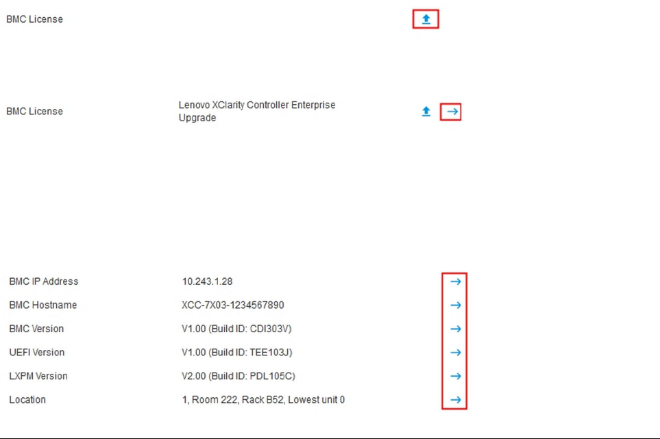
If your server has a license other than the XClarity Controller Enterprise license, you may be able to purchase
a license upgrade to enable enhanced features. To install the upgrade license after you have obtained an
upgrade license, click the upward-pointing arrow icon.
To add, delete or export a license, click the rightward-pointing arrow icon.
To change the relevant settings for the BMC IP address, BMC host name, UEFI version, BMC version and
location items, click the right-ward pointing arrow.
• For the IP address and host name, you will be led to the Ethernet Configuration section under Network.
• For the UEFI and BMC version items, you will be led to the Firmware Update page.
• For the location item, you will be led to the Server Properties section on the Server Configuration page.
Viewing the System Utilization
By clicking Utilization in the left pane, a summary of common server utilization information is provided.
System utilization is a composite metric based on the real-time utilization of processor, memory, and I/O
subsystems. The utilization data are all coming from the ME(Node manager) side, which includes the
following:
• CPU Utilization
– Aggregated C-State Residency
– Measured time in C0 as a percentage of the used and max C0 residency (per second).
• Memory Utilization
– Aggregated R/W volume of all Memory Channels.
– Measured bandwidth calculated as a percentage of the used and max memory bandwidth available
(per second).
• I/O Utilization
– Aggregated R/W volume of Root Ports in the PCIe* Bus.
– Measured bandwidth calculated as a percentage of the used and max I/O bandwidth available (per
second).
50
XClarity Controller with Intel Xeon SP (1st, 2nd Gen)User's Guide

Viewing Event Logs
The Event Log provides a historical list of all hardware and management events.
Select the Event Log tab in Events to display the Event Log page. All events in the log are time stamped,
using the XClarity Controller date and time settings. Some events also generate alerts when they occur, if
they are configured to do so in Alert Recipients. You can sort and filter events in the event log.
The following is a description of the actions that can be performed in the Event Log page.
• Customize table: Select this action item to choose the type of information you wish to display in the
table. A sequence number can be displayed to assist in determining the order of events when more than
one event has the same timestamp.
Note: Some sequence numbers are used by internal BMC processes, so it is normal that there may be
gaps in the sequence numbers when the events are sorted by sequence number.
• Clear logs: Select this action item to delete the event logs.
• Refresh: Select this action item to update the display with any event log entries that may have occurred
since the page was last displayed.
• Type: Select which event types to show. The event types include the following:
Shows Error entries in the log
Shows Warning entries in the log
Shows Informational entries in the log
Click each icon to turn off or on the types of errors to be displayed. Clicking the icon successively will
toggle between showing and not showing the events. A blue box surrounding the icon indicates that type
of event will be displayed.
• Source type filter: Select an item from the drop-down menu to display only the type of event log entries
that you wish to be shown.
• Time filter: Select this action item to specify the interval of the events that you want to show.
• Search: To search for specific types of events or keywords, click the magnifying glass icon, and type a
word to search for in the Search box. Note that the input is case-sensitive.
Note: The maximum number of event log records is 1024. When the event logs are full, the new log entry will
automatically overwrite the oldest one.
Viewing Audit Logs
The Audit Log provides a historical record of user actions, such as logging in to the XClarity Controller,
creating a new user, and changing a user password.
You can use the audit log to track and document authentication, changes, and system actions.
Chapter 4. Monitoring the server status 51

Both the event log and the audit log support similar maintenance and viewing actions. To see the description
of the display and filtering actions that can be performed on the Audit Log page, see
“Viewing Event Logs”
on page 51
.
Notes:
• After running Lenovo’s tools on your server operating system, the Audit Log may contain records showing
actions performed by a username (for example user “20luN4SB”) that you may not recognize. When some
of the tools are run on the server operating system, they may create a temporary user account for
accessing the XClarity Controller. The account is created with a random username and password and can
only be used to access the XClarity Controller on the internal Ethernet over USB interface. The account
can only be used to access the XClarity Controller CIM-XML and SFTP interfaces. The creation and
removal of this temporary account is recorded in the audit log as well any actions performed by the tool
with these credentials.
• The maximum number of audit log records is 1024. When the audit logs are full, the new log entry will
automatically overwrite the oldest one.
Viewing the Maintenance History
The Maintenance History page includes information about the firmware update, configuration and hardware
replacement history.
The contents of the maintenance history can be filtered to display certain types of events or certain intervals
of time.
Note: The maximum number of maintenance history records is 250. When the maintenance history logs are
full, the new log entry will automatically overwrite the oldest one.
Configuring Alert Recipients
To add and modify email and syslog notifications or SNMP TRAP recipients, use the information in this topic.
The following is a description of the actions that can be performed in the Alert Recipients tab.
The following actions items can be performed in the Email/Syslog recipients section.
• Create: Select this action item to create additional new Email recipients and Syslog recipients. Up to 12
Email and Syslog recipients can be configured.
– Create Email Recipient: Select this action item to create an Email recipient.
– Enter the name and email address of the recipient.
– Select to enable or disable the event notification. If disable is selected, the account will remain
configured, but no emails will be sent.
– Select the types of events that the recipient will be notified of. If you click the drop-down next to the
Critical, Attention, or System category labels you can select or deselect notifications for specific
components in the category.
– You can choose whether or not to have the event log contents included in the email alert.
– The index specifies which of the 12 recipient slots is assigned.
– You can configure the email server to which the events will be forwarded here or by clicking the
SMTP Server action at the top of the section. See SMTP Server below for configuration details.
– Create Syslog Recipient: Select this action item to create syslog recipients.
– Enter the name and IP address or host name of the Syslog server.
52
XClarity Controller with Intel Xeon SP (1st, 2nd Gen)User's Guide
– Select to enable or disable the event notification. If disable is selected, the account will remain
configured but no emails will be sent.
– The index specifies which of the 12 recipient slots is assigned.
– Select the types of events that will be sent to the Syslog server. If you click the drop-down menu
next to the Critical, Attention, or System category labels you can select or deselect notifications for
specific components in the category.
• SMTP Server: Select this action item to configure the relevant settings for the SMTP Email server. Only
one email server can be configured. The same email configuration is used when sending alerts to all of the
configured email recipients. The BMC automatically switch from an secure connection to an encrypted
connection for mail transfer using the STARTTLS command uniformly via port 587, if the target mail server
supports it.
– Enter the host name or IP address and network port number of the Email server.
– If the Email server requires authentication, select the Require Authentication check box and enter the
username and password. Select the type of authentication that is required by the Email server, either a
challenge-response method (CRAM-MD5) or simple credentials (LOGIN).
– Some networks may block outgoing emails if the reverse path value is not as expected. By default, the
XClarity Controller will use alertmgr@domain, where the domain is the Domain name as specified in the
DDNS section of the XClarity Controller network web page. You can specify your own sender
information in place of the default.
– You can test the connection to the Email server to ensure that the email settings have been configured
correctly. The XClarity Controller will display a message indicating whether or not the connection is
successful.
• Retry and Delay: Select this action item to configure the relevant settings for the retry and delay options.
– The retry limit specifies the number of times that the XClarity Controller will attempt to send an alert if
the initial attempt did not succeed.
– The delay between entries specifies the amount of time that the XClarity Controller will wait after
sending an alert to one recipient before sending an alert to the next recipient.
– The delay between attempts specifies the amount of time that the XClarity Controller will wait after a
failed attempt before retrying to send the alert.
• Protocol: Select this action item to configure the relevant settings for connection protocol.
– You can choose between TCP Protocol or UDP Protocol, please note that this setting will apply to all
syslog recipients.
• If Email or Syslog Recipients have been created, they will be listed in this section.
– To edit the settings for an Email or Syslog Recipient click the pencil icon below the action header on the
row next of the recipient that you wish to configure.
– To delete an Email or Syslog Recipient click the trash can icon.
– To send a test alert to an Email or Syslog Recipient, click the paper airplane icon.
The following actions can be performed in the SNMPv3 user segment.
• Create: Select this action item to create SNMPv3 TRAP recipients.
– Select the user account that is to be associated with the SNMPv3 TRAPs. The user account must be
one of the twelve local user accounts.
– Specify the host name or IP address of the SNMPv3 manager that will receive the SNMPv3 TRAPs.
– The XClarity Controller uses the HMAC-SHA hash algorithm to authenticate with the SNMPv3 manager.
This is the only algorithm supported.
– The privacy password is used with the privacy protocol to encrypt the SNMP data.
Chapter 4. Monitoring the server status 53

– The SNMPv3 global setting applies to all SNMPv3 TRAP recipients. These settings can be configured
while creating an SNMPv3 TRAP recipient or by clicking the SNMPv3 Settings action at the top of the
SNMPv3 user segment.
– Select to enable or disable SNMPv3 TRAPs. If disabled, the settings will remain configured but no
SNMPv3 TRAPs will be sent.
– The BMC Contact and Location information is required and is configured on the Server Properties
web page. See
“Setting Location and Contact” on page 75 for more information.
– Select the types of events that will be cause TRAPs to be sent to the SNMPv3 manager. If you click
the drop-down menu next to the Critical, Attention, or System category labels you can select or
deselect notifications for specific components in the category.
Note: Data transfer between the SNMP client and the agent can be protected using encryption. The
supported methods for privacy protocol are CBC-DES and AES.
• If SNMPv3 TRAP recipients have been created, they will be listed in this section.
– To edit the settings for a SNMPv3 recipient, click the pencil icon below the action header on the row
next of the recipient that you wish to configure.
– To delete a SNMPv3 recipient, click the trash can icon.
Capturing the latest OS failure screen data
Use the information in this topic to capture and view an operating system failure screen.
The operating system screen is automatically captured when the OS Watchdog timeout occurs. If an event
occurs that causes the OS to stop running, the OS Watchdog feature is triggered and the screen contents
are captured. The XClarity Controller stores only one screen capture. When the OS Watchdog timeout
occurs, a new screen capture overwrites the previous screen capture. The OS Watchdog feature must be
enabled to capture the OS failure screen. To set the OS Watchdog Time, see
“Setting server timeouts” on
page 76
for more information. The OS failure screen capture feature is available only with the XClarity
Controller Advanced or Enterprise Level of functionality. See the documentation for your server for
information about the level of XClarity Controller functionality that is installed in your server.
Click the Latest Failure Screen action in the Remote Console section of the XClarity Controller home page
to view an image of the operating system display that was captured when the OS Watchdog timeout
occurred. The capture can also be viewed by clicking Service, then Latest Failure Screen in the Quick
Action section of the home page. If the system has not experienced an OS Watchdog timeout and captured
the OS screen, a message indicating that the failure screen has not been created is displayed.
54
XClarity Controller with Intel Xeon SP (1st, 2nd Gen)User's Guide

Chapter 5. Configuring the Server
Use the information in this chapter to understand the options available for server configurations.
When configuring the server, the following options are available:
• Adapters
• Boot options
• Power policy
• Server properties
• Chassis
Note: This item is only available on D3 V2 Chassis compatible nodes.
Viewing the adapter information and configuration settings
Use the information in this topic to view information about the adapters installed in the server.
Click Adapters under Server Configuration to view information about the adapters installed in the server.
Notes:
• If the adapter does not support status monitoring, it will not be visible for monitoring or configuration. For
inventory related information of all the installed PCI adapters, refer to the Inventory page.
Configuring system boot mode and order
To configure the system boot mode and order, use the information in this topic.
When you select Boot Options under Server Configuration , you can configure the system boot mode and
order.
Note: No unauthenticated in-band method is allowed to change security related system settings. For
example, Secure Boot must NOT be able to configure over unauthenticated in-band APIs from the OS or
UEFI shell. This includes OneCLI running in-band and obtaining temporary credentials using IPMI, or any
tools and APIs to configure Secure Boot, TPM, UEFI Setup password related settings. All security related
settings must require proper authentication with sufficient privilege.
For the system boot mode, the following two options are available:
UEFI Boot
Select this option to configure a server that supports Unified Extensible Firmware Interface (UEFI). If you
are booting UEFI-enabled operating systems, this option might shorten boot time by disabling legacy
option ROMs.
Legacy Boot
Select this option if you are configuring a server to boot an operating system that requires legacy (BIOS)
firmware. Select this option only if you are booting non-UEFI enabled operating systems.
To configure the system boot order, select a device from the list of Available devices and click the right
arrow to add the device to the boot order. To remove a device from the boot order, select a device from the
© Copyright Lenovo 2017, 2022 55

boot order list and click the left arrow to move the device back to the list of available devices. To change the
boot order, select a device and click the up or down arrow to move the device up or down in priority.
When you make a change to the boot order, you must select a restart option before applying the change. The
following options are available:
• Restart server immediately: The boot order changes are saved and the server is restarted immediately
without shutting down the operating system.
• Restart server normally: The boot order changes are saved and the operating system is shutdown
before restarting the server.
• Manually restart later: The boot order changes will be saved, but will not take effect until the next time
the server is rebooted.
Configuring one-time boot
To temporarily ignore the configured boot and instead boot to a specified device one time, use the
information in this topic.
Click Boot Options under Server Configuration and select a device from the drop-down menu to configure
the device that the system will boot to one-time on the next server restart. The following choices are
available:
PXE network
Sets up your server to attempt a Preboot Execution Environment network boot.
Primary removable media
The server is booted from the default USB device.
Default CD/DVD
The server is booted from the default CD/DVD drive.
F1 system setup
The server is booted into the Lenovo XClarity Provisioning Manager.
Diagnostic Partition
The server is booted into the Diagnostics section of the Lenovo XClarity Provisioning Manager.
Default Hard Disk
The server is booted from the default disk drive.
Primary remote media
The server is booted from the mounted virtual media.
No one-time boot
The configured boot order is used. There is no one-time boot override of the configured boot order.
When you change the type of boot to be performed with the one-time boot device, you can also specify the
boot to be a legacy boot or a UEFI boot. Click the Prefer Legacy Boot check box if you would like the boot
to be a legacy BIOS boot. Uncheck the box if would like a UEFI boot. When you select a one-time change to
the boot order, you must select a restart option before applying the change.
• Restart server immediately: The boot order change is saved and the server is restarted immediately
without shutting down the operating system.
• Restart server normally: The boot order change is saved and the operating system is shutdown before
restarting the server.
• Manually restart later: The boot order change is saved, but will not take effect until the next time the
server is rebooted.
56
XClarity Controller with Intel Xeon SP (1st, 2nd Gen)User's Guide

Managing the server power
To view power management information and perform power management functions, use the information in
this topic.
Select Power Policy under Server Configuration to view power management information and perform
power management functions.
Note: In a chassis containing blade or high-density server nodes, the chassis cooling and power is
controlled by the chassis management controller instead of the XClarity Controller.
Configuring the power redundancy
To configure the power redundancy, use the information in this topic.
Available fields in the Power Redundancy section include the following:
• Redundant (N+N): There are two or more independent power sources that are capable of supplying
power to the system simultaneously. This means that if one or more power sources fails, the other source
(s) can continue to supply power to the system without any interruption. N+N redundancy provides a high
level of fault tolerance and ensures that the system remains operational even in the event of multiple
failures.
– Zero Output Mode: Once enabled under Redundant configuration, some PSUs will automatically enter
into standby state under light load conditions. In this manner, the remaining PSU delivers the entire
power load to increase efficiency.
• Redundant (N+1): There is one primary power source that is capable of supplying power to the system.
Additionally, there is at least one backup power source that is available to take over if the primary source
fails. The backup source is designed to provide enough power to keep the system running until the
primary source can be repaired or replaced. N+1 redundancy provides a lower level of fault tolerance
compared to N+N redundancy.
• Non-redundant mode: In this mode, the server is not guaranteed to remain operational if a power supply
is lost. The server will throttle if a power supply fails in an attempt to remain running.
Click Apply after making the configuration changes.
Configuring the power capping policy
To configure the power capping policy, use the information in this topic.
You can choose to enable or disable the power capping function. If power capping is enabled, a selection
can be made to limit the amount of power used by the server. If power capping is disabled, the maximum
power used by the server is determined by the Power Redundancy policy. To change the setting, first click
Reset. Choose your preferred setting; then, click Apply.
Power capping can be enabled using AC power consumption measurements or DC power consumption
measurements. From the drop-down menu, select the type of measurements that will be used to determine
the power capping limit. When switching between AC and DC, the number on the slider will change
accordingly.
There are two ways to change the power capping value:
• Method 1: Move the slider mark to the desired wattage to set the overall server power limit.
• Method 2: Input the value in the input box. The slider mark will automatically move to the corresponding
position.
Chapter 5. Configuring the Server 57

Click Apply after making the configuration changes.
Note: The Power Policies option is not available when the XClarity Controller is in a chassis containing
blade or high-density server nodes. The power policy is controlled by the chassis management controller
instead of the XClarity Controller.
Configuring the power restore policy
To configure how the server reacts when the power is restored after a power loss, use the information in this
topic.
When configuring the power restore policy, the following three options are available:
Always Off
The server will remain powered off even when power is restored.
Restore
The server will automatically be powered on when power is restored if the server was powered on at the
time that the power failure occurred. Otherwise, the server power will remain off when power is restored.
Always On
The server will automatically power on when power is restored.
Click Apply after making the configuration changes.
Note: The Power Restore Policies option is not available in a chassis containing blade or high-density
server nodes. The power restore policy is controlled by the chassis management controller instead of the
XClarity Controller.
Power actions
See the information in this topic to understand the power actions that can be made to the server.
Click Power Action in the Quick Action section of the XClarity Controller homepage.
The following table contains a description of the power and restart actions that can be performed on the
server.
Table 6. Power actions and descriptions
Two column table containing descriptions of the server power and restart actions.
Power Action
Description
Power on server
Select this action item to power on the server and boot
the operating system.
Power off server normally Select this action item to shut down the operating system
and power off the server.
Power off server immediately Select this action item to power off the server without first
shutting down the operating system.
Restart server normally
Select this action item to shut down the operating system
and power cycle the server.
Restart server immediately
Select this action item to power cycle the server
immediately without first shutting down the operating
system.
58 XClarity Controller with Intel Xeon SP (1st, 2nd Gen)User's Guide

Table 6. Power actions and descriptions (continued)
Power Action
Description
Boot server to system setup Select this item to power on or reboot the server and
automatically boot into system setup without needing to
press F1 during boot.
Trigger non-maskable interrupt (NMI) Select this action item to force a Non-maskable Interrupt
(NMI) on a “hung” system. Selection of this action item
allows the platform operating system to perform a
memory dump that can be used for debug purposes of
the system hang condition. The auto reboot on NMI
setting from the F1 system setup menu determines
whether or not the XClarity Controller will reboot the
server after the NMI.
Schedule power actions Select this action item to schedule daily and weekly
power and restart actions for the server.
Restart management controller
Select this action item to restart the XClarity Controller
AC Power Cycle Server Select this action to power cycle the server.
Note: If the operating system is in the screen saver or locked mode when a shutdown of the operating system is
attempted, the XClarity Controller might not be able to initiate a normal shutdown. The XClarity Controller will perform
a hard reset or shutdown after the power off delay interval expires, while the operating system might still be running.
Note: If the power LED on the front panel is rapidly blinking, the XClarity Controller may not be able to initiate a normal
power-on sequence. The XClarity Controller can power on the system once the power LED begins to blink slowly.
Managing and monitoring power consumption with IPMI commands
Use the information in this topic to manage and monitor power consumption using IPMI commands.
This topic describes how the Intel Intelligent Power Node Manager and the Data Center Manageability
Interface (DCMI) can be used to provide power and thermal monitoring and policy-based power
management for a server using Intelligent Platform Management Interface (IPMI) power management
commands.
For servers using Intel Node Manager SPS 3.0, XClarity Controller users can use IPMI power management
commands provided by Intel's Management Engine (ME) to control the Node Manager features and to
monitor server power consumption. Server power management can also be accomplished using DCMI
power management commands. Example Node Manager and DCMI power management commands are
provided in this topic.
Managing the server power using Node Manager commands
Use the information in this topic to manage the server power using the Node Manager.
The Intel Node Manager firmware does not have an external interface; therefore, the Node Manager
commands must first be received by the XClarity Controller and then sent to the Intel Node Manager. The
XClarity Controller functions as a relay and a transport device for the IPMI commands using standard IPMI
bridging.
Note: Changing Node manager policies using Node Manager IPMI commands might create conflicts with
the XClarity Controller power management functionality. By default, bridging of the Node Manager
commands is disabled to prevent any conflict.
Chapter 5. Configuring the Server 59
For users who want to manage the server power using the Node Manager instead of the XClarity Controller,
an OEM IPMI command consisting of (network function: 0x3A) and (command: 0xC7) is available for use.
To enable native Node Manager IPMI commands type:ipmitool -H <$XClarity_Controller_IP> -U <USERID>
-P <PASSW0RD> raw 0x3a 0xc7 0x01
To disable native Node Manager IPMI commands type:ipmitool -H <$XClarity_Controller_IP> -U
<USERID> -P <PASSW0RD> raw 0x3a 0xc7 0x00
The following information are examples of Node Manager power management commands.
Notes:
• By specifying IPMI channel 0 and a target address of 0x2c, you can use the IPMITOOL to send
commands to the Intel Node Manager for processing. A request message is used to initiate an action and
a response message is returned to the requester.
• Commands are displayed in the following format due to space limitations.
Power monitoring using the Get Global System Power Statistics, (command code 0xC8): Request:
ipmitool -H <$XClarity_Controller_IP> -U <USERID> -P <PASSW0RD> -b 0x00 -t 0x2c raw 0x2E 0xC8
0x57 0x01 0x00 0x01 0x00 0x00 Response:57 01 00 38 00 04 00 41 00 39 00 ec 56 f7 53 5a 86 00 00 50
Power capping using the Set Intel Node Manager Policy, (command code 0xC1): Request:ipmitool -H <
$XClarity_Controller_IP> -U <USERID> -P <PASSW0RD> -b 0x00 -t 0x2c raw 0x2e 0xC1 0x57 0x01 0x00
0x10 0x01 0xA0 0x00 0x00 0x00 0x60 0xea 0x00 0x00 0x00 0x00 0x1e 0x00Response:57 01 00
Power savings using the Set Intel Node Manager Policy, (command code 0xC1): Request:ipmitool -H <
$XClarity_Controller_IP> -U <USERID> -P <PASSW0RD> -b 0x00 -t 0x2c raw 0x2e 0xC1 0x57 0x01 0x00
0x10 0x01 0x00 0x00 0x00 0x00 0x60 0xea 0x00 0x00 0x00 0x00 0x1e 0x00
Get device ID function using the Get Intel Management Engine Device ID:Request:ipmitool -H <
$XClarity_Controller_IP> -U <USERID> -P <PASSW0RD> -b 0x00 -t 0x2c raw 0x06 0x01Response:50 01
03 05 02 21 57 01 00 05 0b 03 40 20 01
For additional Intel Node Manager commands, see the latest release of the Intel Intelligent Power Node
Manager External Interface Specification Using IPMI at
https://businessportal.intel.com.
Managing the server power using DCMI commands
Use the information in this topic to manage the server power using DCMI commands.
The DCMI provides monitoring and control functions that can be exposed through standard management
software interfaces. Server power management functions can also be accomplished using DCMI commands.
The following information are examples of commonly used DCMI power management functions and
commands. A request message is used to initiate an action and a response message is returned to the
requester.
Note: Commands are displayed in the following formats due to space limitations.
Get Power Reading: Request:ipmitool -H <$XClarity_Controller_IP> -U <USERID> -P <PASSW0RD> raw
0x2c 0x02 0xdc 0x01 0x00 0x00 Response:dc 39 00 38 00 3b 00 39 00 e3 6f 0a 39 e8 03 00 00 40
Set Power Limit: Request:ipmitool -H <$XClarity_Controller_IP> -U <USERID> -P PASSW0RD raw 0x2c
0x04 0xdc 0x00 0x00 0x00 0x00 0xA0 0x00 0xe8 0x03 0x00 0x00 0x00 0x00 0xe8 0x03 Response:dc
60
XClarity Controller with Intel Xeon SP (1st, 2nd Gen)User's Guide

Get Power Cap: Request:ipmitool -H <$XClarity_Controller_IP> -U <USERID> -P <PASSW0RD> raw 0x2c
0x03 0xdc 0x00 0x00 Response:dc 00 00 00 a0 00 e8 03 00 00 00 00 01 00
Activate the Power Limit: Request:ipmitool -H <$XClarity_Controller_IP> -U <USERID> -P
<PASSW0RD> raw 0x2c 0x05 0xdc 0x01 0x00 0x00 Response:dc
Deactivate the Power Limit: Request:ipmitool -H <$XClarity_Controller_IP> -U <USERID> -P
<PASSW0RD> raw 0x2c 0x05 0xdc 0x00 0x00 0x00 Response:dc
Note: On some servers, the Exception Actions for the Set Power Limit command might not be supported.
For example, the Hard Power Off system and log events to SEL parameter might not be supported.
For the complete list of commands that are supported by the DCMI specification, see the latest release of the
Data Center Manageability Interface Specification at
https://www.intel.com/content/dam/www/public/us/
en/documents/technical-specifications/dcmi-v1-5-rev-spec.pdf
.
Remote Console Functionality
Use the information in this topic to understand how to remotely view and interact with the server console.
You can use the remote console functionality in the XClarity Controller web interface to view and interact with
the server console. You can assign a disk image (ISO or IMG file) as a virtual drive on the server. The remote
console functionality is available with the XClarity Controller Advanced and XClarity Controller Enterprise
features and is only available through the web interface. You must log in to the XClarity Controller with a user
ID that has Supervisor access or Remote Console Access privileges to use the remote console features. For
more information about upgrading from XClarity Controller Standard to XClarity Controller Advanced or
XClarity Controller Enterprise, see
“Upgrading XClarity Controller” on page 6.
Use the remote console features to do the following:
• Remotely view video with graphic resolution up to 1280 x 1024 at 72 or 75Hz, regardless of the server
state.
• Remotely access the server using the keyboard and mouse from a remote client.
• Mount ISO and IMG files that are located on your local system or on a remote system as virtual drives that
are available for use by the server.
• Upload an IMG or ISO image to the XClarity Controller memory and mount it to the server as a virtual
drive. Up to two files with a maximum total size of 50 MB may be uploaded into the XClarity Controller
memory.
Notes:
• When the remote console feature is started in multi-user mode, (the XClarity Controller with the XClarity
Controller Enterprise feature set supports up to six simultaneous sessions), the remote disk feature can be
exercised by only one session at a time.
• The remote console is able to display only the video that is generated by the video controller on the
system board. If a separate video controller adapter is installed and is used in place of the system's video
controller, the XClarity Controller remote console cannot display the video content from the added
adapter.
• If you have firewalls in your network, a network port must be opened to support the remote console
feature. To view or change the network port number used by the remote console feature, see
“Service
Enablement and Port Assignment” on page 33
.
• The remote console feature uses HTML5 for displaying the server video on web pages. To use this feature
your browser must support displaying video content using HTML5 elements.
Chapter 5. Configuring the Server 61
• If you are using self-signed certificates and an IPv6 address to access the BMC with the Internet Explorer
browser, the remote console session may fail to start due to a certificate error. To avoid this issue, the
self-signed certificate can be added to the Internet Explorer Trust Root certificate Authorities:
– Select Security under BMC Configuration and download the self-signed certificate.
– Change certificate file extension to *.crt and double-click the Web certificate file.
– Clear IE11 browser cache.
– Click Install Certificate to install the certificate to the Certificate Store by following the Certificate
Import Wizard steps.
Enabling the remote console functionality
This topic provides information about the remote console functionality.
As mentioned earlier, the XClarity Controller remote console functionality is available only in the XClarity
Controller Advanced and XClarity Controller Enterprise features. If you do not have the privilege to operate
the remote console, you will see a lock icon.
After you have purchased and obtained the activation key for the XClarity Controller Advanced upgrade
install it using the instructions under
“Installing an activation key” on page 85.
To use the remote console functionality, complete the following steps:
1. Click the image with a white diagonally pointing arrow in the Remote Console section of the XClarity
Controller homepage or the Remote Console web page.
2. Select one of the following modes:
• Start remote console in single-user mode
• Start remote console in multiuser mode
Note: The XClarity Controller with XClarity Controller Enterprise feature set supports up to six
simultaneous video sessions in the multiuser mode.
3. Select whether or not to allow others to request to send a disconnection request to a remote console
user when someone wishes to use the remote console feature and the feature is already in use in Single
User Mode, or when the maximum number of users are using the remote console feature in Multi User
Mode. The No response time interval specifies how long the XClarity Controller will wait before
automatically disconnecting the user if no response is received to the disconnection request.
4. Select whether or not to allow record the latest three server boot videos.
5. Select whether or not to allow record the latest three server crash videos.
6. Select whether or not to allow OS failure screen capture with HW error.
7. Click Launch Remote Console to open the remote console page in another tab. When all possible
remote console sessions are in use, a dialog box will pop up. From this dialog box, the user can send a
disconnection request to a remote console user who has enabled the setting to Allow others to request
my remote session disconnect. The user can accept or deny the request to disconnect. If the user
does not respond within the interval specified by the No response time interval setting, the user
session will automatically be ended by the XClarity Controller.
Remote power control
This topic explains how to send server power and restart commands from the remote console window.
You can send server power and restart commands from the remote console window without returning to the
main web page. To control the server power with the remote console, click Power and select one of the
following commands:
62
XClarity Controller with Intel Xeon SP (1st, 2nd Gen)User's Guide
Power On Server
Select this action item to power on the server and boot the operating system.
Power Off Server Normally
Select this action item to shut down the operating system and power off the server.
Power Off Server Immediately
Select this action item to power off the server without first shutting down the operating system.
Restart Server Normally
Select this action item to shut down the operating system and power cycle the server.
Restart Server Immediately
Select this action item to power cycle the server immediately without first shutting down the operating
system.
Boot Server to System Setup
Select this item to power on or reboot the server and automatically boot into system setup without
needing to press F1 during boot.
Remote console capture screen
Use the information in this topic to understand how to use the remote console screen capture feature.
The screen capture feature in the remote console window captures the video display contents of the server.
To capture and save a screen image, complete the following steps:
Step 1. In the remote console window, click Capture Screen.
Step 2. In the pop-up window, click Save File and press OK. The file will be named rpviewer.png and will
be saved to your default download folder.
Note: The screen capture image is saved as a PNG file type.
Remote console keyboard support
In the remote console window under Keyboard, the following option items are provided:
• Click Virtual Keyboard to launch the virtual keyboard. This feature is useful if you are using a tablet
device that does not have a physical keyboard. The following options can be used to create macros and
key combinations that can be sent to the server. The operating system on the client system that you are
using may trap certain key combinations (for example Ctrl+Alt+Del) instead of transmitting them to the
server. Other keys, such as F1 or Esc, may be intercepted by the program or browser that you are using.
Macros provides a mechanism to send keystrokes to the server that the user might not be able to send.
• Click Server Macros to use server defined macros. Some server macros are predefined by the XClarity
Controller firmware. Other server defined macros can be defined using Lenovo XClarity Essentials and
downloaded from the XClarity Controller. These macros are defined for all users of the remote console
feature.
• Click Configure to add or remove user defined macros. The user defined macros are defined only for the
current remote console user. Other remote console users will not see each other’s user defined macros.
– Click the Add Macros icon and press the key sequences that you desire; then, click Add to add a new
macro.
– To remove a user defined macro, select the macro from the list and click the trash can icon.
– To send a user defined macro to the server select the User Defined Macros option, and click on the
macro that you want to send.
Chapter 5. Configuring the Server 63
Remote console mouse support
Use this information to understand the options for remote mouse control.
The remote console window offers several options for mouse control, including absolute mouse control,
relative mouse control (no acceleration), and mouse control (RHEL, older Linux).
Absolute and relative mouse control
Use this information to access the absolute and relative options for controlling the mouse.
To access the absolute and relative options for controlling the mouse, complete the following steps:
Step 1. In the remote console window, click Mouse.
Step 2. Click Mouse Settings from the drop-down menu.
Step 3. Select one of the following Mouse Acceleration modes:
Absolute Positioning (Windows, Newer Linux & Mac OS X)
The client sends mouse location messages to the server that are relative to the origin (upper
left area) of the viewing area.
Relative Positioning, no acceleration
The client sends the mouse location as an offset from the previous mouse position.
Relative Positioning (older Linux)
This mode applies an acceleration factor to align the mouse better on some Linux targets. The
acceleration settings have been selected to maximize compatibility with older Linux
distributions.
Screen Video Record/Replay
Use the information in this topic to record or replay remote presence screen videos.
The XClarity Controller web interface provides a DVR-like feature to support recording and playback remote
presence screen videos. This function only supports video recording to a network folder. Currently, NFS and
CIFS protocols are supported. Below are the steps in using the record and replay function.
1. On the remote console web page, click Screen Recording to open the settings window.
2. In the settings window, the following information may need to be specified.
• If the “CIFS” mount type is selected, specify the Remote Folder, User Name, and Password
parameters. The format for the CIFS remote folder is “//<remote IP address>/<folder name>”. For
example: //xxx.xxx.xxx.xxx/folder.
• If the “NFS” mount type is selected, specify the Remote Folder parameter. The format for the NFS
remote folder is “<remote IP address>:/<folder name>”. For example: xxx.xxx.xxx.xxx:/folder.
• Specify the video file name if necessary. If a file name has already been provided, an error message
box will shown. To overwrite the existing file name, choose “Overwrite File Name”. If the “Auto” box is
ticked, the video file name will be automatically generated.
• “Max File Size” denotes the maximum video file size before the video recording will automatically
stop.
• “Max Recording Duration” denotes the maximum video recording duration before the recording will
automatically stop.
3. Click Start Recording to start the video recording.
4. Click Stop Recording to stop the video recording. A popup window saying “Video Recording
Completed” will appear, showing relevant video recording information.
64
XClarity Controller with Intel Xeon SP (1st, 2nd Gen)User's Guide
5. Download the recorded videos from NFS or CIFS to your local folder. In the Remote Console Preview
section of the XClarity Controller homepage, click Recorded Videos and select the video file to replay.
Remote console screen modes
Use the information in this topic to configure the remote console screen modes.
To configure the remote console screen modes, click Screen Mode .
The following menu options are available:
Full Screen
This mode fills the client desktop with the video display. Pressing the Esc key in this mode will exit full
screen mode. Because the remote console menu is not visible in full screen mode, you will have to exit
full screen mode to use any of the features provided by the remote console menu such as the keyboard
macros.
Fit Screen
This is the default setting when the remote console is launched. In this setting, the target desktop is
completely displayed without scroll bars. The aspect ratio is maintained.
Scaling Screen
With scaling enabled, the video image is sized so that the complete image is scaled to fill the console
window.
Origin Screen
The video image has the same dimensions as the server end. Scroll bars are displayed if needed to allow
viewing of video image areas that do not fit within the window.
Color Mode
Adjusts the color depth of the remote console window. There are two color-mode choices:
• Color: 7, 9, 12, 15, and 23 bit
• Grayscale: 16, 32, 64, and 128 shades
Note: Color mode adjustments are usually made if your connection to the remote server has limited
bandwidth and you wish to reduce the bandwidth demand.
Media mount methods
Use the information in this topic to understand how to perform media mounts.
Three mechanisms are provided to mount ISO and IMG files as virtual drives.
• Virtual drives can be added to the server from the remote console session by clicking Media.
• Directly from the remote console web page, without establishing a remote console session.
• Standalone tool
Users need Remote Console and Remote Disk Access privileges to use the virtual media features.
Files can be mounted as virtual media from your local system or from a remote server, and can be accessed
over the network or uploaded into the XClarity Controller memory using the RDOC feature. These
mechanisms are described below.
• Local media are ISO or IMG files that are located on the system that you are using to access the XClarity
Controller. This mechanism is only available through the remote console session, not directly from the
Chapter 5. Configuring the Server 65
remote console web page and is only available with the XClarity Controller Enterprise features. To mount
local media, click Activate in the Mount Local Media section. Up to four files can be concurrently
mounted to the server.
Notes:
– When using the Google Chrome browser, an additional mounting option called Mount files/folders is
available to let you drag and drop the file(s)/folder.
– If multiple concurrent remote console sessions are in progress with an XClarity Controller, this feature
can be activated only by one of the sessions.
• Files that are located on a remote system can also be mounted as virtual media. Up to four files can be
concurrently mounted as virtual drives. The XClarity Controller supports the following file sharing
protocols:
– CIFS - Common Internet File System:
– Enter the URL that locates the file on the remote system.
– If you want the file to be presented to the server as read-only virtual media, tick the check box.
– Enter the credentials that are needed for the XClarity Controller to access the file on the remote
system.
Note: The XClarity Controller does not support spaces in the user name, password, or URL. Make
sure that the CIFS server does not have login credentials configured with a space in the user name
or password and that the URL does not contain a space.
– Mount options are optional and defined by the CIFS protocol.
– If the remote server belongs to a collection of servers, where the security is centrally handled, enter
the domain name to which the remote server belongs.
– NFS - Network File System:
– Enter the URL that locates the file on the remote system.
– If you want the file to be presented to the server as read-only virtual media, tick the checkbox.
– Mount options are optional and defined by the NFS protocol. Both NFSv3 and NFSv4 are supported.
For example, to use NFSv3, you need to specify option ‘nfsvers=3’. If the NFS server uses AUTH_
SYS security flavor to authenticate NFS operations, you need to specify option ‘sec=sys’.
– HTTPFS – HTTP Fuse-based File System:
– Enter the URL that locates the file on the remote system
– If you want the file to be presented to the server as read-only virtual media, tick the check box.
Note: Errors may occur during the mounting process for security certificates generated by Microsoft
IIS. If this occurs, see
“Media mount error issues” on page 73.
Click Mount all remote media to mount the file as virtual media. To remove virtual media, click the trash
can icon to the right of the mounted media.
• Up to two files can be uploaded in the XClarity Controller memory and mounted as virtual media using the
XClarity Controller RDOC feature. The total size for both files must not exceed 50 MB. These files will
remain in the XClarity Controller memory until they are removed, even if the remote console session has
ended. The RDOC feature supports the following mechanisms when uploading the files:
– CIFS - Common Internet File System: See the description above for details.
Example:
To mount an ISO file named account_backup.iso that is located on the backup_2016 directory of a
CIFS server at the 192.168.0.100 IP address as a read-only virtual drive on the server, you would fill in
66
XClarity Controller with Intel Xeon SP (1st, 2nd Gen)User's Guide
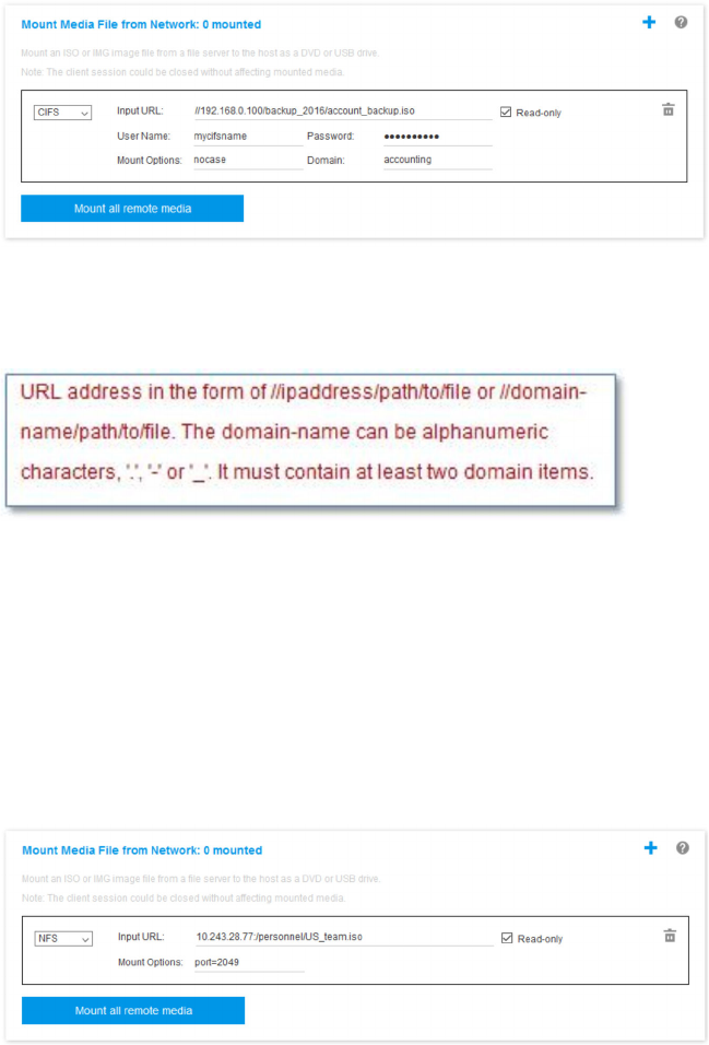
the fields as shown in the figure below. In this example, the server located at 192.168.0.100 is a
member of a collection of servers under the domain “accounting”. The domain name is optional. If your
CIFS server is not part of a domain, leave the Domain field blank. The CIFS “nocase” mount option is
specified in the Mount Options field in this example indicating to the CIFS server that the uppercase/
lowercase checking of the file name should be ignored. The Mount Options field is optional. The
information entered by the user in this field is not used by the BMC and is simply passed on to the CIFS
server when the mount request is made. Refer to the documentation for your CIFS server
implementation to determine which options are supported by your CIFS server.
The BMC provides guidance when specifying the URL. If the URL being entered is not valid, the mount
button will be greyed out and red text will be displayed under the URL field showing the expected
format for the URL.
– NFS - Network File System: See the description above for details.
Example:
To mount an ISO file named US_team.iso that is located on the “personnel” directory of an NFS server
at the 10.243.28.77 IP address as a read-only virtual drive on the server, you would fill in the fields as
shown in the figure below. The NFS “port=2049” mount option specifies that network port 2049 should
be used to transfer the data. The Mount Options field is optional. The information entered by the user
in this field is passed on to the NFS server when the mount request is made. Refer to the
documentation for your NFS server implementation to determine which options are supported by your
NFS server.
The BMC provides guidance when specifying the URL. If the URL being entered is not valid, the mount
button will be greyed out and red text will be displayed under the URL field showing the expected
format for the URL.
Chapter 5. Configuring the Server 67

– HTTPS – Hypertext Transfer Protocol Secure:
– Enter the URL that locates the file on the remote system.
– If you want the file to be presented to the server as read-only virtual media, tick the check box.
– Enter the credentials that are needed for the XClarity Controller to access the file on the remote
system.
Notes:
– Errors may occur during the mounting process for security certificates generated by Microsoft IIS. If
this occurs, see
“Media mount error issues” on page 73.
– The XClarity Controller does not support spaces in the user name, password, or URL. Make sure
that the CIFS server does not have login credentials configured with a space in the user name or
password and that the URL does not contain a space. Example:
To mount an ISO file named EthernetDrivers.ISO that is located on the “newdrivers” directory of a
HTTPS server with the domain name “mycompany.com” using network port 8080 as a read-only
virtual drive on the server, you would fill in the fields as shown in the figure below.
The BMC provides guidance when specifying the URL. If the URL being entered is not valid, the
mount button will be greyed out and red text will be displayed under the URL field showing the
expected format for the URL.
– SFTP – SSH File Transfer Protocol
– Enter the URL that locates the file on the remote system.
– If you want the file to be presented to the server as read-only virtual media, tick the checkbox.
– Enter the credentials that are need to for the XClarity Controller to access the file on the remote
system.
Notes:
– The XClarity Controller does not support spaces in the user name, password, or URL. Make sure
that the CIFS server does not have login credentials configured with a space in the user name or
password and that the URL does not contain a space.
68
XClarity Controller with Intel Xeon SP (1st, 2nd Gen)User's Guide
– When the XClarity Controller connects to a HTTPS server, a pop-up window will appear showing
information of the security certificate used by the HTTPS sever. The XClarity Controller is unable to
verify the authentic of the security certificate.
– LOCAL - Common Internet File System:
– Browse your system for the ISO or IMG file that you want to mount.
– If you want the file to be presented to the server as read-only virtual media, check the check box.
Click Mount all RDOC files to mount the file as virtual media. To remove the virtual media, click the trash
can icon to the right of the mounted media.
Standalone tool
For users that require mounting of the devices or images(.iso / .img) using the XClarity Controller, users can
use the rdmount standalone code part of the OneCLI package. Specifically, rdmount will open a connection
to XClarity Controller and will mount the device or images to the host.
rdmount has the following syntax:
rdmount -s ip_address -d <iso or device path> -l <userid> -p <password> -w port (443)
Example to mount an iso file:
$sudo ./rdmount -s 10.243.11.212 -d /home/user/temp/SLE-15-Installer-DVD-x86_64-RC2-DVD1.iso -l userid -p password -w 443
Remote disk using Java client
This sections describe how to mount local media using Java client.
You can use Java client to assign the server to a CD or DVD drive, a diskette drive, or USB flash drive that is
on your computer, or you can specify a disk image on your computer for the server to use. You can use the
drive for functions such as restarting (booting) the server, updating code, installing new software on the
server, and installing or updating the operating system on the server. Drives and disk images are displayed
as USB drives on the server.
Notes: The Remote Console Java supports one of the following Java environment, and it can be opened
only if the HTML5 client is not running.
1. Oracle Java Runtime Environment 1.8/Java SE 8 or newer versions
2. OpenJDK 8. Distribution of AdoptOpenJDK with HotSpot JVM is supported.
If you use AdoptOpenJDK, you must use
https://openwebstart.com/ under OSX, Windows, and Linux.
Creating an image file
To create a new image file from a specified source folder, complete the following steps:
1. Click the Create Image option under the Virtual Media tab in the Virtual Media Java Client window. The
Create Image from Folder window is displayed.
2. Click the Browse button associated with the Source Folder field to select the specific source folder.
3. Click the Browse button associated with the New Image File field to select the image file to use.
4. Click the Create Image button.
Chapter 5. Configuring the Server 69

Figure 1. Creating an image file
Selecting devices to mount
To mount local image, folder and CD/DVD/USB drive, complete the following steps:
Click the Select Devices to Mount option under the Virtual Media tab in the Virtual Media Java Client
window. The Select Devices to Mount window is displayed.
Figure 2. Select Devices to Mount Window
You can mount local image, folder and CD/DVD/USB drive by performing the following steps:
• Mount Local Image:
1. Click the Add Image button to select the image you want to mount.
2. Check the Mapped option.
70
XClarity Controller with Intel Xeon SP (1st, 2nd Gen)User's Guide

3. Check the Read Only option to enable the function if needed.
4. Click the Mount Selected button and you can mount the local image successfully.
Figure 3. Mount Local Image
• Mount Local Folder:
1. Click the Map Folder button to select the local folder you want to mount.
2. Click the Mount Selected button and you can mount the local folder successfully.
Chapter 5. Configuring the Server 71

Figure 4. Mount Local Folder
• Mount CD/DVD or USB Drive:
1. Click the Scan Drives button to detect plugged CD/DVD or USB Drive.
2. Check the Mapped option.
3. Check the Read Only option to enable the function if needed.
4. Click the Mount Selected button and you can mount the local image successfully.
Figure 5. Mount CD/DVD or USB Drive
72 XClarity Controller with Intel Xeon SP (1st, 2nd Gen)User's Guide

The Select Devices to Mount window contains a list of the current local devices that are available for
mounting. This window contains the following fields and buttons:
• The Mapped field contains the check box that allows you to select the devices to mount or map.
• The Read Only field contains the check box that allows you to select the mapped or mounted devices
that will be read-only on the host server.
• The Drive field contains the device path on the local machine.
• Click the Close button to close the Select Devices to Mount window.
• Click the Add Image button to browse for the diskette image and ISO image file in your local file system
that you want to add to the list of devices.
• Click the Remove Image button to remove an image that has been added to the list of devices.
• Click the Mount Selected button to mount or map all devices that are checked for mounting or mapping
in the Mapped field.
Note: The folder will be mounted as read-only.
• Click the Scan Drives button to refresh the list of local devices.
Selecting devices to unmount
To unmount the host server devices, complete the following steps:
1. Click the Unmount All option under the Virtual Media tab in the Virtual Media Java Client window.
2. After selecting the Unmount All option you are presented with an Unmount All confirmation window. If
you accept, all host server devices on the server are unmounted.
Note: You cannot unmount drives individually.
Figure 6. Unmount All
Media mount error issues
Use the information in this topic to troubleshoot media mount error issues.
Chapter 5. Configuring the Server 73
When using security certificates generated by Microsoft IIS, you may encounter errors during the mounting
process. If this occurs, replace the security certificate with a new one generated by openssl. Specifically, the
newly generated pfx file is loaded into the Microsoft IIS server.
Below is an example showing how the new security certificate is generated via openssl in the Linux operating
system.
$ openssl
OpenSSL>
$ openssl genrsa 1024 > server.key
Generating RSA private key, 1024 bit long modulus
...........................................++++++
.......................................................++++++
e is 65537 (0x10001)
$ openssl req -new -key server.key > server.csr
You are about to be asked to enter information that will be incorporated
into your certificate request.
What you are about to enter is what is called a Distinguished Name or a DN.
There are quite a few fields but you can leave some blank
For some fields there will be a default value,
If you enter '.', the field will be left blank.
-----
Country Name (2 letter code) [AU]:CN
State or Province Name (full name) [Some-State]:BJ
Locality Name (eg, city) []:HD
Organization Name (eg, company) [Internet Widgits Pty Ltd]:Lenovo
Organizational Unit Name (eg, section) []:Lenovo
Common Name (e.g. server FQDN or YOUR name) []:10.245.18.66
Email Address []:test@test.com
Please enter the following 'extra' attributes
to be sent with your certificate request
A challenge password []:
An optional company name []:LNV
$ ls
server.csr server.key
$ openssl req -x509 -days 3650 -key server.key -in server.csr > server.crt
You are about to be asked to enter information that will be incorporated
into your certificate request.
What you are about to enter is what is called a Distinguished Name or a DN.
There are quite a few fields but you can leave some blank
For some fields there will be a default value,
If you enter '.', the field will be left blank.
-----
Country Name (2 letter code) [AU]:CN
State or Province Name (full name) [Some-State]:BJ
Locality Name (eg, city) []:BJ
Organization Name (eg, company) [Internet Widgits Pty Ltd]:LNV
Organizational Unit Name (eg, section) []:LNV
Common Name (e.g. server FQDN or YOUR name) []:10.245.18.66
Email Address []:test@test.com
$ ls
server.crt server.csr server.key
$ openssl pkcs12 -export -out server.pfx -inkey server.key -in server.crt
Enter Export Password:
Verifying - Enter Export Password:
$ ls
server.crt server.csr server.key server.pfx
74 XClarity Controller with Intel Xeon SP (1st, 2nd Gen)User's Guide

Exiting the remote console session
This topic explains how to end your remote console session.
To exit your remote console session, close the remote console and the virtual media session windows.
Downloading service data
Use the information in this topic to collect service information about your server. This process is normally
only done at the request of service personnel to assist in resolving a server problem.
In the XClarity Controller home page, click the Service option in the Quick Action section and select
Download Service Data. Click OK to download the service data.
The process of collecting the service and support data takes a few minutes to generate the service data. The
file will be saved to your default download folder. The naming convention for the service data file follows this
convention:<machine type and model>_<serial number>_xcc_<date>-<time>.tgz
For example: 7X2106Z01A_2345678_xcc_170511-175656.tgz.
In addition to the tgz format, the service data can also be downloaded using the tzz format. Tzz uses a
different compression algorithm and can be extracted with a utility such as “lzop”.
Server Properties
Use the information in this topic to change or view relevant server properties.
Setting Location and Contact
Use the information in this topic to set various parameters to help identify the system for operations and
support personnel.
Select Server Properties under Server Configuration, to configure the Location and Contact information.
Contact
Allows you to specify the name and phone number of the person who should be contacted if the system
experiences a problem.
Note: This field is the same as the Contact field in the SNMPv3 configuration and is required to enable
SNMPv3.
Rack Name
Allows you to locate the server more easily by specifying which rack it is in.
Note: The field is optional and is not configurable in a Flex node.
Room Number
Allows you to locate the server more easily by specifying which room it is in.
Building
Allows you to locate the server more easily by specifying which building it is in.
Lowest U
Allows you to locate the server more easily by specifying the position in the rack.
Note: The field is optional and is not configurable in a Flex node.
Chapter 5. Configuring the Server 75
Address
Allows you to specify the full postal address where the server is located.
Note: When the relevant information has been inputted, it will appear as a single line in the Location field in
the SNMPv3 section and XClarity Controller home page.
Setting server timeouts
Use the information in this topic to set timeouts for the server.
These timeouts are used to restore operation to a server that has hung.
Select Server Properties under Server Configuration, to configure the server timeouts. The following
server timeout selections are provided:
OS Watchdog
The OS watchdog is used to monitor the operating system to ensure that it is not hung. The Ethernet
over USB interface must be enabled for this feature. See
“Configuring Ethernet over USB” on page 32
for details. The XClarity Controller contacts the operating system at an interval configured in the OS
Watchdog Time selection. If the operating system does not respond before it is time for the next check,
the XClarity Controller assumes that the operating system has hung. The XClarity Controller will capture
the contents of the server display and then reboot the server in an attempt to restore operation. The
XClarity Controller will reboot the server only once. If the operating system continues to hang after the
reboot, instead of continually rebooting the server, the server will be left in the hung state so that the
problem can be investigated and corrected. To rearm the OS watchdog, power the server off and back
on. To enable the OS watchdog, select an interval from the OS Watchdog Time drop-down and click
Apply. To disable the OS watchdog, select None on the OS Watchdog Time drop-down menu.
Loader Watchdog
The loader watchdog monitors the interval between the completion of POST and when the operating
system begins running. The Ethernet over USB interface must be enabled for this feature. See
“Configuring Ethernet over USB” on page 32 for details. When POST is completed, the XClarity
Controller starts a timer and begins to contact the operating system. If the operating system does not
respond with the time configured in the Loader Watchdog selection, the XClarity Controller assumes that
the operating system boot has hung. The XClarity Controller will then reboot the server in an attempt to
restore operation. The XClarity Controller will reboot the server only once. If the operating system boot
continues to hang after the reboot, instead of continually rebooting the server, the server will be left in
the hung state so that the problem can be investigated and corrected. The loader watchdog is rearmed
when server is switched off and back on or when the server successfully boots into the operating
system. To enable the loader watchdog, select an interval from the Loader Watchdog drop-down and
click Apply. To disable the loader watchdog select None on the Loader Watchdog drop-down.
Enable Power Off Delay
Use the Power Off Delay field to specify the number of minutes that the XClarity Controller subsystem
will wait for the operating system to shutdown before forcing power off. To set the power off delay
timeout value, select time interval from the drop-down and click Apply. To disable the XClarity Controller
from forcing power off, select None from the drop-down selection.
Trespass message
To create a message that is displayed when a user logs in to the XClarity Controller, use the information in
this topic.
Select Server Properties under Server Configuration. Use the Trespass Message option to configure a
message that you want displayed to the user. When you are finished, click Apply.
76
XClarity Controller with Intel Xeon SP (1st, 2nd Gen)User's Guide

The message text will be displayed in the Message area of the XClarity Controller login page when a user
logs in.
Setting the XClarity Controller date and time
Use the information in this topic to understand XClarity Controller date and time settings. Instructions are
provided to configure the XClarity Controller date and time. The XClarity Controller date and time is used to
time stamp all events that are logged in the event log and alerts that are sent.
At the XClarity Controller home page, click the clock icon on the upper right-hand corner to view or change
the XClarity Controller date and time. The XClarity Controller does not have its own real-time clock. You can
configure the XClarity Controller to sync its time and date with a Network Time Protocol server or with the
server’s real-time clock hardware.
Syncing with NTP
Complete the following steps to synchronize the XClarity Controller clock with the NTP server:
• Select Sync up time with NTP and specify the NTP server address.
• Additional NTP servers can be specified by clicking the “+” icon.
• Specify how frequently you want the XClarity Controller to sync with the NTP server.
• The time obtained from the NTP server is in Coordinated Universal Time (UTC) format.
– If you want the XClarity Controller to adjust its time and date for your local region, select the time zone
offset for your locale from the drop-down menu.
– If your location observes Daylight Saving Time, tick the Automatically adjust for Daylight Saving
Time (DST) checkbox.
• When your configuration changes are complete, click Apply.
Syncing with the Host
The time kept in the server’s real-time clock hardware may be in Coordinated Universal Time (UTC) format or
may already have been adjusted and stored in local time format. Some operating systems store the real-time
clock in UTC format while others store the time as local time. The server real-time clock does not indicate
which format the time is in. Therefore when the XClarity Controller is configured to sync with the host’s real-
time clock, the user can choose how the XClarity Controller uses the time and date that is obtained from the
real-time clock.
• Local (example: Windows): In this mode, the XClarity Controller treats the time and date that is obtained
from the real-time clock as local time with any applicable time zone and DST offsets already applied.
• UTC (example: Linux): In this mode, the XClarity Controller treats the time and date that is obtained from
the real-time clock as Coordinated Universal Time, with no time zone or DST offsets already applied. In
this mode, you can choose to adjust the time and date for your local region by selecting the time zone
offset for your locale from the drop-down menu. If your location observes Daylight Saving Time, you can
also tick the Automatically adjust for Daylight Saving Time (DST) check box.
• When your configuration changes are complete, click Apply.
Notes:
• When daylight saving occurs, any actions that were scheduled for the XClarity Controller to perform
during the interval when the clock jumps forward will not be performed. For example, if the US daylight
start time is 2:00 am on March 12
th
, and a power action is scheduled for 2:10 am on March 12
th
, this
action will not occur. Once the time reaches 2:00 am, the XClarity Controller will instead read the time as
3:00 am.
• XClarity Controller Date and Time settings cannot be modified in a Flex System.
Chapter 5. Configuring the Server 77
78 XClarity Controller with Intel Xeon SP (1st, 2nd Gen)User's Guide

Chapter 6. Configuring the Storage
Use the information in this chapter to understand the options available for storage configurations.
When configuring the storage, following options are available:
• Detail
• RAID setup
RAID Detail
For using RAID detail function, use the information in this topic.
This function displays the storage devices’ physical structure and storage configuration along with details
like their location, manufacturer, product name, status, capacity, interface, media, form factor and other info.
RAID Setup
To perform RAID setup functions, use the information in this topic.
Use the information in this topic to view and configure storage pools, associated virtual disks and drives for
the RAID adapter. If the system is powered off, power it on in order to view the RAID information.
Viewing and configuring the virtual drives
Use the information in this topic to view and configure the virtual drives.
When you select RAID Setup under Server Configuration, the Array Configuration tab will be chosen and
the existing virtual disks will be displayed by default. The logical drives are sorted by disk arrays and
controllers. Detailed information about the virtual disk, such as the virtual disk strip size and bootable
information is displayed.
To configure the RAID settings, click Enable Edit mode.
In edit mode, you can click the controller action menu, view the current RAID virtual disks and create new
RAID virtual disks.
From the Controller Actions menu, you can perform the following actions:
Clear RAID configuration
Clears all the configuration and data on the selected controller.
Manage foreign configuration
Import any foreign drives that were detected. A foreign drive is a drive that was moved from a different
RAID configuration to the current RAID controller
Note: You will be notified if no foreign drives are detected.
Information of the current RAID virtual disks for a particular controller are shown as respective “virtual disk
cards”. Each card displays information such as the virtual disk name, status, capacity and actions. The
pencil icon allows you to edit the information, and the trash can icon enables you to delete the “virtual disk
card”.
© Copyright Lenovo 2017, 2022 79
Note: The capacity and RAID level cannot be changed.
If you click the virtual disk name, a virtual disk properties window will appear.
To create a new RAID virtual disk, follow the steps shown below:
Note: If there is no remaining storage capacity, you are unable to create a new virtual disk.
1. Select drives or a disk array which has free storage capacity
a. When creating a virtual disk in a new disk array, you need to specify the RAID level. If there are not
enough drives to select, and you click Next, an error message will appear under the RAID level field.
For some RAID levels, span is required . There is also a minimum amount of drives that need to be
present in the span.
1) For these types of situations, the web interface will display Span 1 by default.
2) Select the drives and click Add member to add the drives to Span 1. When Span 1 does not
have enough drives, disable the Add Span link.
3) Click Add Span to add Span 2. Select the drives and click Add member to add to Span 2.
4) Click Add member to add drives to the last span. If you want to add drives to Span 1 again, you
need to click Span 1 and select the drives to add to Span 1.
5) If the number of spans reaches the maximum amount, disable Add span.
b. To create virtual disks in an existing disk array, you need to select a disk array that has free capacity.
2. Creating a virtual disk
a. By default, create a virtual disk that uses all the storage capacity. The Add icon is disabled when all
of the storage is used. You can click the pencil icon to change the capacity or other properties.
b. When you edit the first virtual disk to use only some of the storage capacity, the Add icon will be
enabled. Click the icon to show the Add Virtual Disk window.
c. If there is more than one virtual disk, the Remove icon will be enabled. This icon will not be shown if
there is only one virtual disk. When you click the Remove icon, the selected row will be immediately
deleted. There will be no confirmation window as the virtual disk has not been created yet.
d. Click Start Creating Virtual Disk to start the process.
Note: When the controller is not supported, a message will appear.
Viewing and configuring the storage inventory
Use the information in this topic to view and configure the storage inventory.
Under the Storage Inventory tab , you can view and configure disk arrays, associated virtual drives and
drives for the RAID controller.
• For storage devices that support RAID configuration:
1. If the controller includes configured disk arrays, it will display the installed drives based on the disk
array. The following describes the items that appear in the window.
– Table title: Shows the disk array ID, RAID level and the total number of drives.
– Table content: Lists the basic properties - drive name, RAID state, type, serial number, part
number, FRU number and actions. You can go to the Inventory page to view all the properties that
the XClarity Controller can detect.
– Actions: The following shows the action items that can be performed. Some actions will not be
available when the drive is in a different state.
– Assign hot spare: Specifies the drive as global hot spare or a dedicated hot spare.
– Remove hot spare: Removes the drive from the hot spare.
80
XClarity Controller with Intel Xeon SP (1st, 2nd Gen)User's Guide
– Make disk drive offline: Sets the drive to offline.
– Make disk drive online: Sets the drive to online.
– Make disk drive as reusable: Sets the drive to reusable.
– Make disk drive as missing: Sets the drive as missing.
– Make drive good to JBOD: Adds drive to JBOD disk arrangement.
– Make drive unconfigured good: Makes the drive available to be configured into an array, or for
use as an emergency hot spare.
– Make drive unconfigured bad: Marks the drive bad, preventing it from being used in an array
or as an emergency hot spare.
– Make disk drive as prepare for removal: Sets the drive for removal.
2. If the controller includes drives that have not yet been configured, they will be displayed in the Non-
RAID drives table. By clicking the Convert JBOD to Ready to Configure option, a window will
appear showing all the drives that support this action item. You can select one or more drives to
convert.
For storage devices that do not support RAID configuration: The XClarity Controller may not be able to
detect the properties of some drives.
Chapter 6. Configuring the Storage 81
82 XClarity Controller with Intel Xeon SP (1st, 2nd Gen)User's Guide

Chapter 7. Updating Server Firmware
To update server firmware, use information in this topic.
Overview
General Information about updating server firmware.
The Firmware Update option on the navigation panel has 4 features:
• System Firmware: Overview of system firmware status and version. And to perform system firmware
update.
• Auto Promote Primary XCC to Backup: Once enabled, the pending backup bank firmware will be
synced from primary bank after the primary bank pass the Image Stability Metric (ISM) measurement.
• Adapter Firmware: Overview of adapter firmware installed, their status and version. And to perform
adapter firmware update.
The current status and versions of firmware for the BMC, UEFI, LXPM, LXPM drivers, and adapters are
displayed, including the BMC primary and backup versions. There are four categories for the firmware status:
• Active: The firmware is active.
• Inactive: The firmware is not active.
• Pending: The firmware is waiting to become active.
• N/A: No firmware has been installed for this component.
Attention:
• XCC and IMM must be updated to the latest version before updating uEFI. Updating in different order may
result in strange or incorrect behavior.
• Installing the wrong firmware update might cause the server to malfunction. Before you install a firmware
or device-driver update, read any readme and change history files that are provided with the downloaded
update. These files contain important information about the update and the procedure for installing the
update, including any special procedure for updating from an early firmware or device-driver version to the
latest version. As the web browser may contain XCC cache data, it is recommended to reload the web
page after the XCC firmware has been upgraded.
• Some firmware updates require system restarting, which performs firmware activation or internal update.
This process in system booting is called “system maintenance mode”, that does not allow user power
actions temporarily. The mode is also enabled during firmware update. User shall not disconnect AC
power when the system enters maintenance mode.
System, Adapter and PSU Firmware Update
Steps to update System firmware, Adapter firmware and PSU firmware.
To manually apply update for System Firmware, Adapter Firmware and PSU Firmware, complete the
following steps:
1. Click Update Firmware within each feature. The Update Server Firmware window opens.
2. Click Browse to select the firmware update file that you want to use.
3. Navigate to the file you want to select and click Open. You are returned to the Update Server Firmware
window with the selected file displayed.
© Copyright Lenovo 2017, 2022 83
4. Click Next > to begin the upload and verify process on the selected file. A progress meter will be
displayed as the file is being uploaded and verified. You can view this status window to verify that the file
you selected to update is the correct file. For System Firmware, the status window will have information
regarding the type of firmware file that is to be updated such as BMC, UEFI, or LXPM. After the firmware
file is uploaded and verified successfully, click Next to select the device you want to update.
5. Click Update to begin the firmware update. A progress meter shows the progress of the update. When
the firmware update is completed successfully, click Finish. If the update requires the XClarity Controller
to be restarted in order to take effect, a warning message will be displayed. For details on how to restart
the XClarity Controller, see
“Power actions” on page 58.
84
XClarity Controller with Intel Xeon SP (1st, 2nd Gen)User's Guide

Chapter 8. License Management
The Lenovo XClarity Controller License Management allows you to install and manage optional server and
systems management features.
There are multiple levels of XClarity Controller firmware functionality and features available for your server.
The level of the firmware features installed on your server vary based on hardware type.
You can upgrade the XClarity Controller functionality by purchasing and installing an activation key.
To order an activation key, contact your sales representative or business partner.
Use the XClarity Controller web interface or the XClarity Controller CLI to manually install an activation key
that lets you use an optional feature you have purchased. Before activating a key:
• The activation key must be on the system that you are using to login to the XClarity Controller.
• You must have ordered the license key and received its authorization code via mail or e-mail.
See
“Installing an activation key” on page 85, “Removing an activation key” on page 86 or “Exporting an
activation key” on page 86
for information about managing an activation key using the XClarity Controller
web interface. See
“keycfg command” on page 122 for information about managing an activation key using
the XClarity Controller CLI.
To register an ID in administering your XClarity Controller license, click the following link:
https://
fod.lenovo.com/lkms/angular/app/pages/index.htm#/welcome
Additional information about license management for Lenovo servers is available at the following Lenovo
Press website:
https://lenovopress.com/redp4895-using-lenovo-features-on-demand
Installing an activation key
Use the information in this topic to add an optional feature to your server.
To install an activation key, complete the following steps:
Step 1. Click License under BMC Configuration.
Step 2. Click Upgrade License.
Step 3. In the Add a new license window, click Browse; then, select the activation key file to add in the
File Upload window and click Open to add the file or click Cancel to stop the installation. To finish
adding the key, click OK, in the Add Activation Key window, or click Cancel to stop the installation.
The Success window indicates that the activation key is installed.
Notes:
• If the activation key is not valid, an error window will appear.
Step 4. Click OK to close the Success window.
© Copyright Lenovo 2017, 2022 85

Removing an activation key
Use the information in this topic to delete an optional feature from your server.
To remove a activation key, complete the following steps:
Step 1. Click License under BMC Configuration.
Step 2. Select the activation key to remove; then, click Delete.
Step 3. In the Confirm Activation Key Deletion window, click OK to confirm activation key deletion or click
Cancel to keep the key file.
The selected activation key is removed from the server and no longer appears in the License
Management page.
Exporting an activation key
Use the information in this topic to export an optional feature from your server.
To export an activation key, complete the following steps:
Step 1. Click License under BMC Configuration.
Step 2. From the License Management page, select the activation key to export; then, click Export.
Step 3. In the Export the selected license window, click Export to confirm activation key exporting or
click Cancel to cancel the key exporting request.
Step 4. Select the directory to save the file.
The selected activation key is exported from the server.
86
XClarity Controller with Intel Xeon SP (1st, 2nd Gen)User's Guide

Chapter 9. Lenovo XClarity Controller Redfish REST API
The Lenovo XClarity Controller provides a Redfish compliant set of easy-to-use REST APIs that can be used
to access Lenovo XClarity Controller data and services from applications running outside of the Lenovo
XClarity Controller framework.
This allows for easy integration of Lenovo XClarity Controller capabilities into other software, whether the
software is running on the same system as the Lenovo XClarity Controller server, or on a remote system
within the same network. These APIs are based on the industry standard Redfish REST API and are
accessed via the HTTPS protocol.
The XClarity Controller Redfish REST API user guide can be found here:
https://sysmgt.lenovofiles.com/help/
topic/com.lenovo.systems.management.xcc.restapi.doc/xcc_restapi_book.pdf
.
Lenovo provides open source sample Redfish scripts that can be used as reference for developing software
that communicates with Lenovo Redfish REST API. These sample scripts can be found here:
• Python:
https://github.com/lenovo/python-redfish-lenovo
• PowerShell: https://github.com/lenovo/powershell-redfish-lenovo
DMTF specifications related to the Redfish API are available at: https://redfish.dmtf.org/. This website
provides general specifications and other reference material on the Redfish REST API.
© Copyright Lenovo 2017, 2022 87
88 XClarity Controller with Intel Xeon SP (1st, 2nd Gen)User's Guide

Chapter 10. Command-line interface
Use the information in this topic to enter commands that manage and monitor the XClarity Controller without
having to use the XClarity Controller web interface.
Use the XClarity Controller command line interface (CLI) to access the XClarity Controller without having to
use the web interface. It provides a subset of the management functions that are provided by the web
interface.
You can access the CLI through a SSH session. You must be authenticated by the XClarity Controller before
you can issue any CLI commands.
Accessing the command-line interface
Use the information in this topic to access the CLI.
To access the CLI, start an SSH session to the XClarity Controller IP address (see “Configuring serial-to-SSH
redirection” on page 89
for more information).
Logging in to the command-line session
Use the information in this topic to log in to the command line session.
To log in to the command line, complete the following steps:
Step 1. Establish a connection with the XClarity Controller.
Step 2. At the user name prompt, type the user ID.
Step 3. At the password prompt, type the password that you use to log in to the XClarity Controller.
You are logged in to the command line. The command-line prompt is system>. The command-line
session continues until you type exit at the command line. You are logged off and the session is
ended.
Configuring serial-to-SSH redirection
This topic provides information about using the XClarity Controller as a serial terminal server.
Serial-to-SSH redirection enables a system administrator to use the XClarity Controller as a serial terminal
server. A server serial port can be accessed from a SSH connection when serial redirection is enabled.
Note: The CLI console 1 command is used to start a serial redirection session with the COM port.
Example session
$ ssh [email protected]
Password:
system>
All traffic from the SSH session is routed to COM2.
ESC (
© Copyright Lenovo 2017, 2022 89

Type the exit key sequence to return to the CLI. In this example, press Esc and then type a left parenthesis.
The CLI prompt displays to indicate return to the IMM CLI.
system>
Command syntax
Review the guidelines in this topic to understand how to enter commands in the CLI.
Read the following guidelines before you use the commands:
• Each command has the following format:
command [arguments] [-options]
• The command syntax is case sensitive.
• The command name is all lowercase.
• All arguments must immediately follow the command. The options immediately follow the arguments.
• Each option is always preceded by a hyphen (-). An option can be a short option (single letter) or a long
option (multiple letters).
• If an option has an argument, the argument is mandatory, for example:
ifconfig eth0 -i 192.168.70.34 -g 192.168.70.29 -s 255.255.255.0
where ifconfig is the command, eth0 is an argument, and -i, -g, and -s are options. In this example, all
three options have arguments.
• Brackets indicate that an argument or option is optional. Brackets are not part of the command that you
type.
Features and limitations
This topic contains information about CLI features and limitations.
The CLI has the following features and limitations:
• Multiple concurrent CLI sessions are allowed via SSH.
• One command is allowed per line (1024-character limit, including spaces).
• There is no continuation character for long commands. The only editing function is the Backspace key to
erase the character that you just typed.
• The Up Arrow and Down Arrow keys can be used to browse through the last eight commands. The
history command displays a list of the last eight commands, which you can then use as a shortcut to
execute a command, as in the following example:
system > history
0 ifconfig eth0
1 readlog
2 readlog
3 readlog
4 history
system > !0
-state enabled
-c dthens
-i 192.168.70.125
-g 0.0.0.0
-s 255.255.255.0
-n XClarity ControllerA00096B9E003A
-r auto
-d auto
-m 1500
90 XClarity Controller with Intel Xeon SP (1st, 2nd Gen)User's Guide

-b 00:09:6B:9E:00:3A
-l 00:00:00:00:00:00
system >
• In the CLI, the output buffer limit is 2 KB. There is no buffering. The output of an individual command
cannot exceed 2048 characters. This limit does not apply in serial redirect mode (the data is buffered
during serial redirect).
• Simple text messages are used to denote command execution status, as in the following example:
system> power on
ok
system> power state
Power: On
State: System power off/State unknown
system>
• The command syntax is case sensitive.
• There must be at least one space between an option and its argument. For example, ifconfig eth0
-i192.168.70.133 is incorrect syntax. The correct syntax is ifconfig eth0 -i 192.168.70.133.
• All commands have the -h, -help, and ? options, which give syntax help. All of the following examples will
give the same result:
system> power -h
system> power -help
system> power ?
• Some of the commands that are described in the following sections might not be available for your system
configuration. To see a list of the commands that are supported by your configuration, use the help or ?
option, as shown in the following examples:
system> help
system> ?
• In a Flex System, some settings are managed by the CMM and cannot be modified on the XClarity
Controller.
Alphabetical command listing
This topic contains a list of CLI commands in alphabetic order. Links are provided to topics for each
command. Each command topic provides information about the command, its function, syntax, and usage.
The complete list of all XClarity Controller CLI commands, in alphabetical order, is as follows:
• “accseccfg command” on page 107
• “adapter command” on page 168
• “alertcfg command” on page 108
• “alertentries command” on page 154
• “asu command” on page 109
• “backup command” on page 112
• “batch command” on page 156
• “clearcfg command” on page 157
• “clearlog command” on page 94
• “clock command” on page 157
• “console command” on page 107
• “dbgshimm command” on page 171
• “dhcpinfo command” on page 113
Chapter 10. Command-line interface 91
• “dns command” on page 114
• “encaps command” on page 116
• “ethtousb command” on page 116
• “exit command” on page 93
• “fans command” on page 95
• “ffdc command” on page 95
• “firewall command” on page 117
• “fuelg command” on page 105
• “gprofile command” on page 118
• “hashpw command” on page 118
• “help command” on page 93
• “history command” on page 93
• “hreport command” on page 96
• “identify command” on page 158
• “ifconfig command” on page 119
• “info command” on page 158
• “keycfg command” on page 122
• “ldap command” on page 123
• “led command” on page 97
• “mhlog command” on page 97
• “m2raid command” on page 170
• “ntp command” on page 125
• “portcfg command” on page 126
• “portcontrol command” on page 127
• “ports command” on page 128
• “power command” on page 102
• “pxeboot command” on page 106
• “rdmount command” on page 129
• “readlog command” on page 99
• “reset command” on page 104
• “restore command” on page 130
• “restoredefaults command” on page 130
• “roles command” on page 131
• “seccfg command” on page 132
• “set command” on page 132
• “smtp command” on page 133
• “snmp command” on page 133
• “snmpalerts command” on page 135
• “spreset command” on page 159
• “srcfg command” on page 137
• “sshcfg command” on page 138
92
XClarity Controller with Intel Xeon SP (1st, 2nd Gen)User's Guide

• “ssl command” on page 139
• “sslcfg command” on page 140
• “storage command” on page 159
• “storekeycfg command” on page 143
• “syncrep command” on page 144
• “syshealth command” on page 100
• “temps command” on page 101
• “thermal command” on page 145
• “timeouts command” on page 146
• “tls command” on page 147
• “trespass command” on page 147
• “uefipw command” on page 148
• “usbeth command” on page 149
• “usbfp command” on page 149
• “users command” on page 149
• “volts command” on page 101
• “vpd command” on page 102
Utility commands
This topic provides an alphabetic list of utility CLI commands.
There are currently 3 utility commands:
exit command
Use this command to log off the CLI session,
Use the exit command to log off and end the CLI session.
help command
This command displays a list of all commands.
Use the help command to display a list of all commands with a short description for each. You can also type
? at the command prompt.
history command
This command provides a list of previously issued commands.
Use the history command to display an indexed history list of the last eight commands that were issued. The
indexes can then be used as shortcuts (preceded by !) to reissue commands from this history list.
Example:
system> history
0 ifconfig eth0
1 readlog
2 readlog
3 readlog
Chapter 10. Command-line interface 93

4 history
system> ifconfig eth0
-state enabled
-c dthens
-i 192.168.70.125
HISTORY-g 0.0.0.0
-s 255.255.255.0
-n XCCA00096B9E003A
-r auto
-d auto
-m 1500
-b 00:09:6B:9E:00:3A
-l 00:00:00:00:00:00
system>
Monitor commands
This topic provides an alphabetic list of monitor CLI commands.
There are currently 11 monitor commands:
clearlog command
This command is used to clear the IMM event log.
Use the clearlog command to clear the event log of the IMM. You must have the authority to clear event logs
to use this command.
Note: This command is intended only for support personnel use.
The following table shows the arguments for the options.
Table 7. clearlog command
The following table is a one-row two column table consisting of the option and option descriptions.
Option Description
-t <all | platform | audit>
Event type, choose which type of event to clear. If not specified, all
event types will be selected.
Event type descriptions
• all: All event type, including platform event and audit event.
• platform: Platform event type.
• audit: Audit event type.
Example:
system> clearlog
All event log cleared successfully
system> clearlog -t all
All event log cleared successfully
system> clearlog -t platform
Platform event log cleared successfully
system> clearlog -t audit
Audit event log cleared successfully
94 XClarity Controller with Intel Xeon SP (1st, 2nd Gen)User's Guide

fans command
This command is used to display the velocity of the server fans.
Use the fans command to display the speed for each of the server fans.
Example:
system> fans
fan1 75%
fan2 80%
fan3 90%
system>
ffdc command
This command is used to generate a new service data file.
Use the first failure data capture (ffdc) command to generate and transfer service data to Support.
The following list consist of commands to be used with the ffdc command:
• generate, create a new service data file
• status, check status of service data file
• copy, copy existing service data
• delete, delete existing service data
The following table shows the arguments for the options.
Table 8. ffdc command
The following table is a multi-row three column table consisting of the options, option descriptions, and
associated values for the options.
Option Description
Values
-t
Type number
1 (processor dump) and 4 (service data). The processor dump contains
all logs and files available. The service data contains only a subset of the
logs and files. The default value is 1.
-f
1
Remote filename or sftp
target directory.
For sftp, use full path or trailing / on directory name (~/ or /tmp/). The
default value is the system generated name.
-ip
1
Address of the tftp/sftp
server
-pn
1
Port number of the tftp/sftp
server
The default value is 69/22.
-u
1
Username for the sftp server
-pw
1
Password for the sftp server
1. Additional argument for generate and copy commands
Syntax:
ffdc [options]
option:
-t 1 or 4
-f
-ip ip_address
Chapter 10. Command-line interface 95

-pn port_number
-u username
-pw password
Example:
system> ffdc generate
Generating ffdc...
system> ffdc status
Type 1 ffdc: in progress
system> ffdc copy -t 1 -ip 192.168.70.230 -u User2 -pw Passw0rd -f /tmp/
Waiting for ffdc.....
Copying ffdc...
ok
system> ffdc status
Type 1 ffdc: completed
8737AC1_DSY0123_xcc_120317-153327.tgz
system> ffdc generate
Generating ffdc...
system> ffdc status
Type 1 ffdc: in progress
system> ffdc status
Type 1 ffdc: in progress
system> ffdc copy -ip 192.168.70.230
Copying ffdc...
ok
system> ffdc status
Type 1 ffdc: completed
8737AC1_DSY0123_xcc_120926-105320.tgz
system>
hreport command
Use this command to show embedded health report.
The following table shows the hreport commands.
Table 9. hreport commands
The following table is a multi-row two column table consisting of the different hreport command descriptions.
Option Description
generate
Create new health report
status
Check status
copy
Copy existing health report
delete Delete existing health report
The following table shows the arguments for the generate and copy options.
Table 10. generate and copy command
The following table is a multi-row two column table consisting of the generate and copy command options
and option descriptions.
96
XClarity Controller with Intel Xeon SP (1st, 2nd Gen)User's Guide

Table 10. generate and copy command (continued)
Option Description
-f Remote filename or sftp target directory (default is system generated name ((for sftp,
use full path or trailing / on directory name (~/ or /tmp/))
-ip Address of tftp/sftp server
-pn
Port number of tftp/sftp server (default 69/22)
-u
Username for sftp server
-pw
Password for sftp server
mhlog command
Use this command to display maintenance history activity log entries.
The following table shows the arguments for the options.
Table 11. mhlog command
The following table is a multi-row two column table consisting of the options and option descriptions.
Option Description
-c <count>
Display 'count' entries (1-250)
-i <index> Display entries starting at index (1-250)
-f Remote filename of log file
-ip
Address of tftp/sftp server
-pn
Port number of tftp/sftp server (default 69/22)
-u
Username for sftp server
-pw
Password for sftp server
Example
Display will look something like this:
Type Message Time
------------- ------------ ----
Hardware SAS Backplane1(SN: XXXX9CE009L) is added. 05/08/2020,04:23:18
Hardware CPU 1(SKU NO: 50844440) is added. 05/08/2020,04:23:22
Hardware CPU 2(SKU NO: 50844440) is added. 05/08/2020,04:23:22
Hardware M2 Card(SN: R1SH9AJ0037) is added. 05/08/2020,04:23:22
Firmware Primary XCC firmware is updated to TGBT99T by XCC Web. 05/08/2020,06:40:37
Firmware Primary XCC firmware is activated to TGBT99T . 05/08/2020,06:41:26
Hardware PSU1(SN: D1DG94C0075) is added. 05/08/2020,06:43:28
led command
Use this command to display and set LED states.
The led command displays and sets the server LED states.
• Running the led command with no options displays the status of the front panel LEDs.
Chapter 10. Command-line interface 97

• The led -d command option must be used with led -identify on command option.
The following table shows the arguments for the options.
Table 12. led command
The following table is a multi-row three column table consisting of the options, option descriptions, and
associated values for the options.
Option Description
Values
-l
Get the status of all system and system
subcomponent LEDs
-chklog Turn off check log LED off
-identify Change state of enclosure identify LED off, on, blink
-d Turn on identification LED for specified time
period
Time period (seconds)
Syntax:
led [options]
option:
-l
-chklog off
-identify state
-d time
Example:
system> led
Fault Off
Identify On Blue
Chklog Off
Power Off
system> led -l
Label Location State Color
Battery Planar Off
BMC Heartbeat Planar Blink Green
BRD Lightpath Card Off
Channel A Planar Off
Channel B Planar Off
Channel C Planar Off
Channel D Planar Off
Channel E Planar Off
Chklog Front Panel Off
CNFG Lightpath Card Off
CPU Lightpath Card Off
CPU 1 Planar Off
CPU 2 Planar Off
DASD Lightpath Card Off
DIMM Lightpath Card Off
DIMM 1 Planar Off
DIMM 10 Planar Off
DIMM 11 Planar Off
DIMM 12 Planar Off
DIMM 13 Planar Off
DIMM 14 Planar Off
DIMM 15 Planar Off
DIMM 16 Planar Off
98 XClarity Controller with Intel Xeon SP (1st, 2nd Gen)User's Guide
DIMM 2 Planar Off
DIMM 3 Planar Off
DIMM 4 Planar Off
DIMM 5 Planar Off
DIMM 6 Planar Off
DIMM 7 Planar Off
DIMM 8 Planar Off
DIMM 9 Planar Off
FAN Lightpath Card Off
FAN 1 Planar Off
FAN 2 Planar Off
FAN 3 Planar Off
Fault Front Panel (+) Off
Identify Front Panel (+) On Blue
LINK Lightpath Card Off
LOG Lightpath Card Off
NMI Lightpath Card Off
OVER SPEC Lightpath Card Off
PCI 1 FRU Off
PCI 2 FRU Off
PCI 3 FRU Off
PCI 4 FRU Off
Planar Planar Off
Power Front Panel (+) Off
PS Lightpath Card Off
RAID Lightpath Card Off
Riser 1 Planar Off
Riser 2 Planar Off
SAS ERR FRU Off
SAS MISSING Planar Off
SP Lightpath Card Off
TEMP Lightpath Card Off
VRM Lightpath Card Off
system>
readlog command
This command displays the IMM event logs.
Use the readlog command to display the IMM event log entries. Five event logs are displayed at a time. The
entries are displayed from the most recent to the oldest.
readlog displays the first five entries in the event log, starting with the most recent, on its first execution,
and then the next five for each subsequent call.
readlog -a displays all entries in the event log, starting with the most recent.
readlog -f resets the counter and displays the first 5 entries in the event log, starting with the most recent.
readlog -date date displays event log entries for the specified date, specified in mm/dd/yy format. It can
be a pipe (|) separated list of dates.
readlog -sev severity displays event log entries for the specified severity level (E, W, I). It can be a pipe (|)
separated list of severity levels.
readlog -i ip_address sets the IPv4 or IPv6 IP address of the TFTP or SFTP server where the event log is
saved. The -i and -l command options are used together to specify the location.
readlog -l filename sets the file name of the event log file. The -i and -l command options are used
together to specify the location.
readlog -pn port_number displays or sets the port number of the TFTP or SFTP server (default 69/22).
readlog -u username specifies the user name for the SFTP server.
Chapter 10. Command-line interface 99
readlog -pw password specifies the password for the SFTP server.
Syntax:
readlog [options]
option:
-a
-f
-date date
-sev severity
-i ip_address
-l filename
-pn port_number
-u username
-pw password
Example:
system> readlog -f
1 I 2017-06-17T09:31:59.217 Remote Login Successful. Login ID: USERID
from SSH at IP address 10.134.78.180
2 I 2017-06-17T07:23:04.685 Remote Login Successful. Login ID: USERID
from webguis at IP address 10.134.78.180.
3 I 2017-06-16T11:00:35.581 Login ID: USERID from webguis at IP address 10.134.78.180 has logged off.
4 I 2017-06-16T11:00:15.174 Login ID: USERID from webguis at IP address 10.104.209.144 has logged off.
5 I 2017-06-16T10:40:14.352 Login ID: USERID from webguis at IP address 10.104.209.144 has logged off.
system> readlog
6 E SERVPROC 12/18/03 10:09:31 Fan 2 Fault. Multiple fan failures
7 E SERVPROC 12/18/03 10:09:31 Fan 1 Fault. Single fan failure
8 I SERVPROC 12/18/03 10:09:25 Ethernet[0] Link Established at 100Mb, Full Duplex.
9 I SERVPROC 12/18/03 10:09:24 Ethernet[0] configured to do Auto Speed/Auto Duplex.
10 I SERVPROC 12/18/03 10:09:24 Ethernet[0] MAC Address currently
being used: 0x00-09-6B-CA-0C-80
system>
syshealth command
This command provides a summary of the health or active events.
Use the syshealth command to display a summary of the health or active events of the server. The power
state, system state, hardware state (includes fan, power supply, storage, processor, memory), restart count,
and IMM software status are displayed.
Syntax:
syshealth [argument]
argument:
summary -display the system health summary
activeevents -display active events
cooling - display cooling devices health status
power - display power modules health status
storage - display local storage health status
processors - display processors health status
memory - display memory health status
Example:
system> syshealth summary
Power On
State OS booted
Restarts 29
system> syshealth activeevents
No Active Event Available!
100 XClarity Controller with Intel Xeon SP (1st, 2nd Gen)User's Guide

temps command
This command displays all temperature and temperature threshold information.
Use the temps command to display all the temperatures and temperature thresholds. The same set of
temperatures are displayed as in the web interface.
Notes:
1. The output has the following column headings:
WR: warning reset (Positive-going Threshold Hysteresis value)
W: warning (Upper non-critical Threshold)
T: temperature (Current value)
SS: soft shutdown (Upper critical Threshold)
HS: hard shutdown (Upper non-recoverable Threshold)
2. All temperature values are in degrees Fahrenheit/Celsius.
3. N/A represents not applicable.
volts command
Use this command to display the server voltage information.
Use the volts command to display all the voltages and voltage thresholds. The same set of voltages are
displayed as in the web interface.
Note: The output has the following column headings:
HSL: hard shutdown low (Lower non-recoverable Threshold)
Chapter 10. Command-line interface 101

SSL: soft shutdown low (Lower critical Threshold)
WL: warning low (Lower non-critical Threshold)
WRL: warning reset low (Negative-going Threshold Hysteresis value)
V: voltage (current value)
WRH: warning reset high (Positive-going Threshold Hysteresis value)
WH: warning high (Upper non-critical Threshold)
SSH: soft shutdown high (Upper critical Threshold)
HSH: hard shutdown high (Upper non-recoverable Threshold)
vpd command
This command displays configuration and informational data (vital product data) associated with the
hardware and software of the server.
Use the vpd command to display vital product data for the system (sys), IMM (bmc), server BIOS (uefi),
Lenovo XClarity Provisioning Manager (lxpm), server firmware (fw), server components (comp) and PCIe
devices (pcie). The same information is displayed as in the web interface.
Syntax:
vpd sys - displays Vital Product Data for the system
vpd bmc - displays Vital Product Data for the management controller
vpd uefi - displays Vital Product Data for system BIOS
vpd lxpm - displays Vital Product Data for system LXPM
vpd fw - displays Vital Product Data for the system firmware
vpd comp - displays Vital Product Data for the system components
vpd pmem - displays Vital Product Data for Intel Optane PMem
vpd pcie - displays Vital Product Data for PCIe devices
Example:
system> vpd bmc
Type Status Version Build ReleaseDate
---- ------- ----- ------
BMC (Primary) Active 0.00 DVI399T 2017/06/06
BMC (Backup) Inactive 1.00 TEI305J 2017/04/13
system>
Server power and restart control commands
This topic provides an alphabetic list of power and restart CLI commands.
There are currently 4 server power and restart commands:
power command
This command describes how to control the server power.
Use the power command to control the server power. To issue power commands, you must have the
Remote Server Power/Restart Access authority level.
The following table contains a subset of commands that can be used with the power command.
102
XClarity Controller with Intel Xeon SP (1st, 2nd Gen)User's Guide

Table 13. power command
The following table is a multi-row three column table consisting of the power commands, command
descriptions, and associated values for the commands.
Command
Description
Value
power on
Use this command to turn on the server power. on, off
power off Use this command to turn off the server power.
Note: The -s option shuts down the operating system
before the server is turned off.
on, off
power cycle Use this command to turn off the server power and then
turn on the server power.
Note: The -s option shuts down the operating system
before the server is turned off.
power enterS3
Use this command to place the operating system into the
S3 (sleep) mode.
Note: This command is used only when the operating
system is on. The S3 mode is not supported on all servers.
power rp
Use this option to specify the host power restore policy.
alwayson|alwaysoff|restore
power
S3resume
Use this command to wake up the operating system from
the S3 (sleep) mode.
Note: This command is used only when the operating
system is on. The S3 mode is not supported on all servers.
power state
Use this command to display the server power state and
the current state of the server.
on, off
The following table contains the options for the power on, power off, and power cycle commands.
Table 14. power command
The following table is a multi-row three column table consisting of the options, option descriptions, and
associated values for the options.
Option Description
Values
-s
Use this option to shut down the operating system
before the server is turned off.
Note: The -s option is implied when using the -every
option for the power off and power cycle commands.
-every
Use this option with the power on, power off, and
power cycle commands to control the server power.
You can set up the dates, times, and frequency (daily
or weekly) to power on, power off, or power cycle your
server.
Note: The values for this option are presented
on separate lines due to space limitations.
Sun|Mon|Tue|Wed|Thu|
Fri|Sat|Day|clear
-t
Use this option to specify the time in hours and minutes
to power on the server, shut down the operating
system, and power off or restart the server.
Use the following format: hh:mm
Chapter 10. Command-line interface 103

Table 14. power command (continued)
Option Description
Values
-d Use this option to specify the date to power on the
sever. This is an additional option for the power on
command.
Note: The -d and -every options, cannot be used
together on the same command.
Use the following format: mm/dd/yyyy
-clear Use this option to clear the scheduled power on date.
This is an additional option for the power on
command.
Syntax:
power on
power off [-s]
power state
power cycle [-s]
The following information are examples of the power command.
To shut down the operating system and power off the server every Sunday at 1:30, enter the following
command:
system> power off
-every Sun -t 01:30
To shut down the operating system and restart the server every day at 1:30, enter the following command:
system> power cycle
-every Day -t 01:30
To power on the server every Monday at 1:30, enter the following command:
system> power on
-every Mon -t 13:00
To power on the server on Dec 31 2013 at 11:30 PM, enter the following command:
system> power on
-d 12/31/2013 -t 23:30
To clear a weekly power cycle, enter the following command:
system> power cycle
-every clear
reset command
This command describes how to reset the server.
Use the reset command to restart the server. To use this command, you must have power and restart
access authority.
The following table shows the arguments for the options.
Table 15. reset command
The following table is a multi-row three column table consisting of the options, option descriptions, and
associated values for the options.
104
XClarity Controller with Intel Xeon SP (1st, 2nd Gen)User's Guide

Table 15. reset command (continued)
Option Description
Values
-s
Shut down the operating system before the
server is reset.
-d Delay performing the reset for the given number
of seconds.
0 - 120
-nmi
Generate a non-maskable interrupt (NMI) on the
server.
Syntax:
reset [option]
option:
-s
-d
-nmi
fuelg command
This command displays information about the server power.
Use the fuelg command to display information about server power usage and configure server power
management. This command also configures policies for power redundancy loss. The following table shows
the arguments for the options.
Table 16. fuelg command
The following table is a multi-row three column table consisting of the options, option descriptions, and
associated values for the options.
Option Description
Values
-pme
Enable or disable power management and capping on the
server.
on, off
-pcapmode Set the power capping mode for the server. input, output
-pcap
A numeric value that falls within the range of power
capping values displayed when running the fuelg
command, with no options, on the target.
numeric wattage value
-history Display power consumption or performance history pc, perf
-period A numeric value to display history (1, 6, 12, 24 hours) numeric value in hours
-pm
Set the policy mode for loss of redundant power.
• bt- basic with throttling
• rt- redundant with throttling (default)
• ort- N_1 redundant with throttling
-zm
Enable or disable zero output mode. This setting can only
be set when the policy mode is set to redundant with
throttling.
on, off
Chapter 10. Command-line interface 105

Table 16. fuelg command (continued)
Option Description
Values
-perf Display the current compute utilization, including system,
microprocessor, and I/O.
percentage
-pc
Display current power consumption
• output- display current DC power
consumption. For Rack and Tower
servers it will include the power
consumption of the system, CPU,
memory and other components, For ITE
blade servers it will only include the
system power consumption.
• input- Display current input power
consumption, including system power
consumption.
Syntax:
fuelg [options]
option:
-pme on|off
-pcapmode input|output
-pcap
-history
-period
-pm bt|r|rt
-zm on|off
-perf
-pc input|output
Example:
system> fuelg
-pme: on
system>
pxeboot command
This command displays and sets the condition of the Preboot eXecution Environment.
Running pxeboot with no options, returns the current Preboot eXecution Environment setting. The following
table shows the arguments for the options.
Table 17. pxeboot command
The following table is a single-row three column table consisting of the option, option description, and
associated values for the option.
Option Description
Values
-en
Sets the Preboot eXecution
Environment condition for
the next system restart.
enabled, disabled
Syntax:
pxeboot [options]
option:
-en state
106 XClarity Controller with Intel Xeon SP (1st, 2nd Gen)User's Guide

Example:
system> pxeboot
-en disabled
system>
Serial redirect command
This topic contains the serial redirect command.
There is only one serial redirect command: the “console command” on page 107.
console command
This command is used to start a serial redirect console session.
Use the console command to start a serial redirect console session to the designated serial port of the IMM.
Syntax:
console 1
Configuration commands
This topic provides an alphabetic list of configuration CLI commands.
There are currently 41 configuration commands:
accseccfg command
Use this command to display and configure account security settings.
Running the accseccfg command with no options displays all account security information. The following
table shows the arguments for the options.
Table 18. accseccfg command
The following table is a multi-row three column table consisting of the options, option descriptions, and
associated values for the options.
Option Description
Values
-am
Sets user authentication method. local, ldap, localldap, ldaplocal
-lp Lockout period after maximum login
failures (minutes).
Between 0 and 2880, 0 = lockout period does not
expire
-pe
Password expiration time period
(days).
Between 0 and 365, 0 = never expire
-pew
Password expiration warning time
period
Note: The Password expiration
warning time period must be less than
Password expiration time period.
Between 0 and 30, 0 = never warn
-pc
Password complexity rules enabled. on, off
-pl Password length. If password complexity rules are enabled, the password
length is between 8 and 32. Otherwise, it is between 0
and 32.
Chapter 10. Command-line interface 107

Table 18. accseccfg command (continued)
Option Description
Values
-ci Minimum password change interval
(hours).
between 0 and 240, 0 = change immediately
-lf Maximum number of login failures. Between 0 and 10, 0 = never locked
-chgdft Change default password after first
login.
on, off
-chgnew Change new user password after first
login.
on, off
-rc
Password reuse cycle. Between 0 and 10, 0 = reuse immediately
-wt
Web and Secure Shell inactivity
session timeout (minutes).
Between 0 and 1440
Example:
system> accseccfg
-legacy
-am local
-lp 2
-pe 0
-pr off
-pd 1
-pl 4
-ci 0
-lf 0
-chgdft off
-chgnew off
-rc 0
-wt user
system>
alertcfg command
Use this command to display and configure the IMM global remote alert parameters.
108
XClarity Controller with Intel Xeon SP (1st, 2nd Gen)User's Guide

Running the alertcfg command with no options displays all global remote alert parameters. The following
table shows the arguments for the options.
Table 19. alertcfg command
The following table is a multi-row three column table consisting of the options, option descriptions, and
associated values for the options.
Option Description
Values
-dr Sets wait time between retries before
the IMM resends an alert.
0 to 4.0 minutes, in 0.5 minute increments
-da Sets wait time before the IMM sends
an alert to the next recipient in the list.
0 to 4.0 minutes, in 0.5 minute increments
-rl
Sets the number of additional times
that the IMM attempts to send an
alert, if previous attempts were
unsuccessful.
0 to 8
Syntax:
alertcfg [options]
options:
-rl retry_limit
-dr retry_delay
-da agent_delay
Example:
system>alertcfg
-dr 1.0
-da 2.5
-rl 5
system>
asu command
This command is used to configure UEFI settings.
Advanced Settings Utility commands (ASU) are used to configure UEFI settings. The host system must be
rebooted for any UEFI setting changes to take effect.
The following table contains a subset of commands that can be used with the asu command.
Table 20. asu command
The following table is a multi-row three column table consisting of a subset of commands that can be used in
conjunction with the asu command. Descriptive information and associated values for the commands are
provided.
Command
Description
Value
delete Use this command to delete an instance or record of a
setting. The setting must be an instance that allows
deletion, for example, iSCSI.AttemptName.1.
setting_instance
help Use this command to display help information for one or
more settings.
setting
Chapter 10. Command-line interface 109

Table 20. asu command (continued)
Command
Description
Value
set
Use this command to change the value of a setting. Set
the UEFI setting to the input value.
Notes:
• Set one or more setting/value pairs.
• The setting can contain wildcards if it expands to a
single setting.
• The value must be enclosed in quotes if it contains
spaces.
• Ordered list values are separated by the equal symbol
(=). For example, set B*.Bootorder "CD/DVD Rom=Hard
Disk 0=PXE Network."
setting value
showgroups Use this command to display the available setting groups.
This command displays the names of known groups.
Group names may vary depending on the installed
devices.
setting
show Use this command to display the current value of one or
more settings.
setting
showvalues Use this command to display all possible values for one or
more settings.
Notes:
• This command will display information about the
allowable values for the setting.
• The minimum and maximum number of instances
allowed for the setting is displayed.
• The default value will be displayed if available.
• The default value is enclosed with opening and closing
angle brackets (< and >).
• Text values show the minimum and maximum length
and regular expression.
setting
Notes:
• In the command syntax, setting is the name of a setting that you want to view or change, and value is the value that
you are placing on the setting.
• Setting can be more than one name, except when using the set command.
• Setting can contain wildcards, for example an asterisk (*) or a question mark (?).
• Setting can be a group, a setting name, or all.
Examples of the syntax for the asu command are presented in the following list:
• To display all of the asu command options enter asu --help.
• To display verbose help for all commands enter asu -v --help.
• To display verbose help for one command enter asu -v set --help.
• To change a value enter asu set setting value.
• To display the current value enter asu show setting.
• To display settings in long batch format enter asu show -l -b all
• To display all possible values for a setting enter asu showvalues setting. Example show values command:
system> asu showvalues S*.POST*
110 XClarity Controller with Intel Xeon SP (1st, 2nd Gen)User's Guide

SystemRecovery.POSTWatchdogTimer==<Disable>=Enable
SystemRecovery.POSTWatchdogTimerValue=numeric min=5 max=20 step=1 default=5
system>
The following table shows the arguments for the options.
Table 21. asu options
The following table is a multi-row three column table consisting of the options, option descriptions, and
associated values for the options.
Option Description
Values
-b Display in batch format.
--help
1
Display command usage and
options. The --help option is placed
before the command, for example
asu --help show.
--help
1
Display help for the command. The
--help option is placed after the
command, for example, asu show
--help.
-l Long format setting name (include
the configuration set).
-m
Mixed format setting name (use the
configuration id).
-v
2
Verbose output.
1. The --help option can be used with any command.
2. The -v option is used only between asu and the command.
Syntax:
asu [options] command [cmdopts]
options:
-v verbose output
--help display main help
cmdopts:
--help help for the command
Note: See individual commands for more command options.
Use the asu transaction commands to set multiple UEFI settings and create and execute batch mode
commands. Use the tropen and trset commands to create a transaction file containing multiple settings to
be applied. A transaction with a given id is opened using the tropen command. Settings are added to the set
using the trset command. The completed transaction is committed using the trcommit command. When
you are finished with the transaction, it can be deleted with the trrm command.
Note: The UEFI settings restore operation will create a transaction with an id using a random three digit
number.
The following table contains transaction commands that can be used with the asu command.
Table 22. asu transaction commands
The following table is a multi-row three column table consisting of the transactions commands, the
command descriptions, and associated values for the commands.
Chapter 10. Command-line interface 111

Table 22. asu transaction commands (continued)
Command
Description
Value
tropen id This command creates a new transaction file containing
several settings to be set.
Id is the identifying string, 1 - 3
alphanumeric characters.
trset id This command adds one or more settings or value pairs to
a transaction.
Id is the identifying string, 1 - 3
alphanumeric characters.
trlist id This command displays the contents of the transaction file
first. This can be useful when the transaction file is created
in the CLI shell.
Id is the identifying string, 1 - 3
alphanumeric characters.
trcommit id This command commits and executes the contents of the
transaction file. The results of the execution and any errors
will be displayed.
Id is the identifying string, 1 - 3
alphanumeric characters.
trrm id This command removes the transaction file after it has
been committed.
Id is the identifying string, 1 - 3
alphanumeric characters.
Example of establishing multiple UEFI settings:
asu tropen TR1
asu trset TR1 UEFI.BootModes.SystemBootMode "UEFI and Legacy"
asu trset TR1 BootOrder.BootOrder "CD/DVD Rom=Hard Disk 0=PXE Network"
asu trset TR1 BootOrder.WolBootOrder "CD/DVD Rom=Hard Disk 0=PXE Network"
asu trset TR1 UEFI.DevicesandIOPorts.Com1BaudRate 115200
asu trset TR1 UEFI.DevicesandIOPorts.Com1DataBits 8
asu trset TR1 UEFI.DevicesandIOPorts.Com1FlowControl Disable
asu trset TR1 UEFI.DevicesandIOPorts.Com1Parity None
asu trset TR1 UEFI.DevicesandIOPorts.Com1StopBits 1
asu trset TR1 UEFI.DevicesandIOPorts.COMPort1 Enable
asu trcommit TR1
backup command
Use this command to create a backup file containing the current system security settings.
The following table shows the arguments for the options.
Table 23. backup command
The following table is a multi-row three column table consisting of the options, option descriptions, and
associated values for the options.
Option Description
Values
-f Backup file name Valid file name
-pp
Password or pass-phrase used to encrypt passwords
inside the backup file
Valid password or quote-delimited pass-phrase
-ip
IP address of TFTP/SFTP server
Valid IP address
-pn
Port number of TFTP/SFTP server Valid port number (default 69/22)
-u
Username for SFTP server
Valid user name
-pw
Password for SFTP server
Valid password
-fd Filename for XML description of backup CLI
commands
Valid filename
112 XClarity Controller with Intel Xeon SP (1st, 2nd Gen)User's Guide

Syntax:
Example:
system> backup f xcc-back.cli pp xxxxxx ip 192.168.70.200
ok
system>
dhcpinfo command
Use this command to view the DHCP server-assigned IP configuration for eth0.
Use the dhcpinfo command to view the DHCP server-assigned IP configuration for eth0, if the interface is
configured automatically by a DHCP server. You can use the ifconfig command to enable or disable DHCP.
Syntax:
dhcpinfo eth0
The following table describes the output from the example.
Table 24. dhcpinfo command
The following table is a multi-row two column table describing the options that are used in the previous
example.
Option Description
-server
DHCP server that assigned the configuration
-n
Assigned host name
Chapter 10. Command-line interface 113

Table 24. dhcpinfo command (continued)
Option Description
-i Assigned IPv4 address
-g
Assigned gateway address
-s
Assigned subnet mask
-d Assigned domain name
-dns1
Primary IPv4 DNS server IP address
-dns2
Secondary IPv4 DNS IP address
-dns3
Tertiary IPv4 DNS server IP address
-i6 IPv6 address
-d6 IPv6 domain name
-dns61
Primary IPv6 DNS server IP address
-dns62
Secondary IPv6 DNS IP address
-dns63
Tertiary IPv6 DNS server IP address
dns command
Use this command to view and set the DNS configuration of the IMM.
Note: In a Flex System, DNS settings cannot be modified on the IMM. DNS settings are managed by the
CMM.
Running the dns command with no options displays all DNS configuration information. The following table
shows the arguments for the options.
Table 25. dns command
The following table is a multi-row three column table consisting of the options, option descriptions, and
associated values for the options.
Option Description
Values
-state
DNS state on, off
-ddns
DDNS state
enabled, disabled
-i1 Primary IPv4 DNS server IP address IP address in dotted decimal IP address format.
-i2
Secondary IPv4 DNS IP address IP address in dotted decimal IP address format.
-i3
Tertiary IPv4 DNS server IP address IP address in dotted decimal IP address format.
-i61
Primary IPv6 DNS server IP address IP address in IPv6 format.
-i62
Secondary IPv6 DNS IP address IP address in IPv6 format.
-i63
Tertiary IPv6 DNS server IP address IP address in IPv6 format.
-p
IPv4/IPv6 priority
ipv4, ipv6
Syntax:
dns [options]
114 XClarity Controller with Intel Xeon SP (1st, 2nd Gen)User's Guide

option:
-state state
-ddns state
-i1 first_ipv4_ip_address
-i2 second_ipv4_ip_address
-i3 third_ipv4_ip_address
-i61 first_ipv6_ip_address
-i62 second_ipv6_ip_address
-i63 third_ipv6_ip_address
-p priority
Note: The following example shows an IMM configuration where DNS is disabled.
Example:
system> dns
-state : disabled
-i1 : 0.0.0.0
-i2 : 0.0.0.0
-i3 : 0.0.0.0
-i61 : ::
-i62 : ::
-i63 : ::
-ddns : enabled
-dnsrc : DHCP
-ddn :
-ddncur : labs.lenovo.com
-p : ipv6
-dscvry : enabled
system>
The following table describes the options used in the previous example.
Table 26. dns command output
The following table is a multi-row two column table describing the options used in the previous example.
Option Description
-state
State of DNS (on or off)
-i1 Primary IPv4 DNS server IP address
-i2 Secondary IPv4 DNS IP address
-i3 Tertiary IPv4 DNS server IP address
-i61
Primary IPv6 DNS server IP address
-i62
Secondary IPv6 DNS IP address
-i63
Tertiary IPv6 DNS server IP address
-ddns
State of DDNS (enabled or disabled)
-dnsrc Preferred DDNS domain name (dhcp or manual)
-ddn Manually specified DDN
-ddncur
Current DDN (read only)
-p
Preferred DNS servers (ipv4 or ipv6)
Chapter 10. Command-line interface 115

encaps command
Use this command to let the BMC quit encapsulation mode.
The following table shows the arguments for the options.
Table 27. encaps command
The following table is a one-row two column table consisting of the options and option descriptions.
Option Description
lite off Let BMC quit encapsulation mode and open global access to all users
ethtousb command
Use the ethtousb command to display and configure Ethernet to Ethernet-over-USB port mapping.
The command allows you to map an external Ethernet port number to a different port number for Ethernet-
over-USB.
Running the ethtousb command with no options displays Ethernet-over-USB information. The following
table shows the arguments for the options.
Table 28. ethtousb command
The following table is a multi-row three column table consisting of the options, option descriptions, and
associated values for the options.
Option Description
Values
-en
Ethernet-over-USB state
enabled, disabled
-mx
Configure port mapping for
index x
Port pair, separated by a colon (:), of the form port1:port2
Where:
• The port index number, x, is specified as an integer from 1 to 10 in the
command option.
• port1 of the port pair is the External Ethernet port number.
• port2 of the port pair is the Ethernet-over-USB port number.
-rm
Remove port mapping for
specified index
1 through 10
Port map indexes are displayed using the ethtousb command with no
options.
Syntax:
ethtousb [options]
option:
-en state
-mxport_pair
-rm map_index
Example:
system> ethtousb -en enabled -m1 100:200 -m2 101:201
system> ethtousb
-en enabled
-m1 100:200
-m2 101:201
system> ethtousb -rm 1
116 XClarity Controller with Intel Xeon SP (1st, 2nd Gen)User's Guide

system>
firewall command
Use this command to configure the firewall to restrict access from certain addresses and optionally limits
access time frame. If no option is specified, the current settings will be displayed.
The following table shows the arguments for the options.
Table 29. firewall command
The following table is a multi-row three column table consisting of the options and option descriptions.
Option Description
Values
-bips
Block 1-3 IP addresses (comma separated,
CIDR or range)
Valid IP addresses
Note: IPv4 and IPv6 addresses can use
CIDR format to block a range of addresses.
-bmacs
Block 1-3 MAC addresses (comma
separated)
Valid MAC addresses
Note: MAC address filtering works only
with specific addresses.
-bbd Block begin date Date with format <YYYY-MM-DD>
-bed Block end date Date with format <YYYY-MM-DD>
-bbt Block begin time Time with format <HH:MM>
-bet Block end time Time with format <HH:MM>
-bti
Block 1-3 time intervals (comma
separated)
e.g., firewall - bti 01:00–02:00,05:05–
10:30 will block access during 01:00-02:00
& 05:05-10:30 every day
Time range with format <HH:MM-HH:MM>
-clr
Clear the firewall rule for a given type
ip, mac, datetime, interval, all
The following options are for IP address blocking
-iplp IP address lockout period in minutes. Numeric value between 0 and 2880, 0 =
never expire
-iplf Maximum number of login failures before
IP address is locked out.
Note: If this value is not 0, then it must be
greater than or equal to <Maximum
number of login failures> that is set by
<accseccfg -lf>
Numeric value between 0 and 32, 0 = never
lock
-ipbl
Show/configure the list of IP addresses
being locked out.
del, clrall, show
• -del: delete an IPv4 or IPv6 address
from block list
• -clrall: clear all blocking IP
• -show: show all blocking IPs
Example:
· “firewall”: Show all options’ value and IP addresses blocking list.
· “firewall -bips 192.168.1.1,192.168.1.0/24,192.168.1.1-192.168.1.5”: Block the access from multi IPs
· “firewall -bti 01:00-02:00,05:05-10:30,14:15-20:00”: Block all access during 01:00-02:00,05:05-10:30,14:15-20:00 every day.
Chapter 10. Command-line interface 117

· “firewall –clr all”: Clear all rules of “Block List and Time Restriction”.
· “firewall -iplp 60”:Set IP address lockout period to 60 minutes.
· “firewall -iplf 5”:Set maximum number of login failures to 5 timesi.
· “firewall -ipbl -del 192.168.100.1”:Delete 192.168.100.1 from IP address blocking list.
· “firewall –ipbl -del 3fcc:1234::2”:Delete 3fcc:1234::2 from IP address blocking list.
· “firewall –ipbl –clrall”: Delete all blocking IP addresses.
· “firewall –ipbl –show”: Show all blocking IP addresses.
gprofile command
Use this command to display and configure group profiles for the IMM.
The following table shows the arguments for the options.
Table 30. gprofile command
The following table is a multi-row three column table consisting of the options, option descriptions, and
associated values for the options.
Option Description
Values
-clear Delete a group enabled, disabled
-n
The name of the group String of up to 63 characters for group_name. The
group_name must be unique.
-a
Role-based authority level
supervisor, operator, rbs <role list>: nsc|am|rca|rcvma|
pr|bc|cel|ac
Role list values are specified using a pipe separated list
of values.
-h Display the command usage and
options
Syntax:
gprofile [1 - 16 group_profile_slot_number] [options]
options:
-clear state
-n group_name
-a authority level:
-nsc network and security
-am user account management
-rca remote console access
-rcvma remote console and remote disk access
-pr remote server power/restart access
-bc basic adapter configuration
-cel ability to clear event logs
-ac advanced adapter configuration
-h help
hashpw command
Use this command with the -sw option to enable/disable the third-party password function or with the -re
option to enable/disable the allowance of retrieving third-party password.
The following table shows the arguments for the options.
118
XClarity Controller with Intel Xeon SP (1st, 2nd Gen)User's Guide

Table 31. hashpw command
The following table is a multi-row three column table consisting of the options, option descriptions, and
associated values for the options.
Option Description
Values
-sw
Third-Party Password switch status enabled, disabled
-re
Third-Party Password read status
Note: Read can be set if the switch is enabled.
enabled, disabled
Example:
system> hashpw –sw enabled –re enabled
system> users -5 –n guest5 –shp ef92b778bafe771e89245b89ecbc08a44a4e166c06659911881f383d4473e94f –a super
system> users -5 ghp
ef92b778bafe771e89245b89ecbc08a44a4e166c06659911881f383d4473e94f
system> users
Account Login ID Advanced Attribute Role Password Expires
------- -------- ------------------ ------ ----------------
1 USERID Native Administrator Password doesn't expire
5 guest5 Third-party Password Administrator 90 day(s)
ifconfig command
Use this command to configure the Ethernet interface.
Type ifconfig eth0 to display the current Ethernet interface configuration. To change the Ethernet interface
configuration, type the options, followed by the values. To change the interface configuration, you must have
at least Adapter Networking and Security Configuration authority.
Note: In a Flex System, the VLAN settings are managed by a Flex System CMM and cannot be modified on
the IMM.
The following table shows the arguments for the options.
Table 32. ifconfig command
The following table is a multi-row three column table consisting of the options, option descriptions, and
associated values for the options.
Option Description
Values
-b
Burned-in MAC Address (read-only
and not configurable)
-state
Interface state disabled, enabled
-c
Configuration method dhcp, static, dthens (dthens corresponds to the try
dhcp server, if it fails use static config option on
the web interface)
-i
Static IP address Address in valid format.
-g
Gateway address Address in valid format.
-s
Subnet mask Address in valid format.
-n
Host name String of up to 63 characters. The string can include
letters, digits, periods, underscores, and hyphens.
Chapter 10. Command-line interface 119

Table 32. ifconfig command (continued)
Option Description
Values
-r
Data rate 10, 100, auto
-d Duplex mode full, half, auto
-m
MTU Numeric between 60 and 1500.
-l LAA MAC address format. Multicast addresses are not
allowed (the first byte must be even).
-dn Domain name Domain name in valid format.
-auto
Autonegotiation setting, which
determines whether the Data rate
and Duplex network settings are
configurable
true, false
-ghn Obtain hostname from DHCP disabled, enabled
-nic
switch NIC mode
1
shared, dedicated, shared:nixX
2
-failover
2
Failover mode none, shared, shared:nicX
-nssync
3
Network setting synchronization enabled, disabled
-address_table Table of automatically-generated
IPv6 addresses and their prefix
lengths
Note: The option is visible only if
IPv6 and stateless auto-
configuration are enabled.
This value is read-only and is not configurable.
-ipv6 IPv6 state disabled, enabled
-lla Link-local address
Note: The link-local address only
appears if IPv6 is enabled.
The link-local address is determined by the IMM.
This value is read-only and is not configurable.
-ipv6static Static IPv6 state disabled, enabled
-i6 Static IP address Static IP address for Ethernet channel 0 in IPv6
format.
-p6 Address prefix length Numeric value between 1 and 128.
-g6
Gateway or default route IP address for the gateway or default route for
Ethernet channel 0 in IPv6.
-dhcp6
DHCPv6 state
enabled, disabled
-sa6 IPv6 stateless autoconfig state enabled, disabled
-vlan Enable or disable the VLAN tagging enabled, disabled
120 XClarity Controller with Intel Xeon SP (1st, 2nd Gen)User's Guide

Table 32. ifconfig command (continued)
Option Description
Values
-vlanid Network packet identification tag for
the IMM
Numeric value between 1 and 4094.
Notes:
1. -nic will also show the status of nic. [active] indicates which nic XCC is currently using
For example:
-nic: shared:nic3
nic1: dedicate
nic2: ext card slot #3
nic3: ext card slot 5 [active]
Indicates that nic3 is in shared mode, on slot 5, nic2 is on slot3, nic1 is XCC dedicated port and XCC is using nic3.
2. The shared:nicX value is available on servers that have an optional mezzanine network card installed. This
mezzanine network card can be used by the IMM.
3. If the IMM is configured to use the dedicated management network port, the -failover option will direct the IMM to
switch to the shared network port if the dedicated port is disconnected.
4. If the failover mode is enabled, the -nssync option directs the IMM to use the same network settings that are used
on the dedicated management network port for the shared network port.
Syntax:
ifconfig eth0 [options]
options:
-state interface_state
-c config_method
-i static_ipv4_ip_address
-g ipv4_gateway_address
-s subnet_mask
-n hostname
-r data_rate
-d duplex_mode
-m max_transmission_unit
-l locally_administered_MAC
-b burned_in_MAC_address
-dn domain_name
-auto state
-nic state
-failover mode
-nssync state
-address_table
-lla ipv6_link_local_addr
-dhcp6 state
-ipv6 state
-ipv6static state
-sa6 state
-i6 static_ipv6_ip_address
-g6 ipv6_gateway_address
-p6 length
-vlan state
-vlanid VLAN ID
Example:
system> ifconfig eth0
-state : enabled
-c : dthens
-ghn : disabled
-i : 192.168.70.125
Chapter 10. Command-line interface 121

-g : 0.0.0.0
-s : 255.255.255.0
-n : IMM00096B9E003A
-auto : true
-r : auto
-d : auto
-vlan : disabled
-vlanid : 1
-m : 1500
-b : 00:09:6B:9E:00:3A
-l : 00:00:00:00:00:00
-dn :
-ipv6 : enabled
-ipv6static : disabled
-i6 : ::
-p6 : 64
-g6 : ::
-dhcp6 : enabled
-sa6 : enabled
-lla : fe80::6eae:8bff:fe23:91ae
-nic : shared:nic3
nic1: dedicate
nic2: ext card slot #3
nic3: ext card slot #5 [active]
-address_table :
system> ifconfig eth0 -c static -i 192.168.70.133
These configuration changes will become active after the next reset of the IMM.
keycfg command
Use this command to display, add, or delete activation keys.
Activation keys control access to optional IMM functionality.
Notes:
• When the keycfg command is run without any options, the list of installed activation keys is displayed.
Key information displayed includes an index number for each activation key, the type of activation key, the
date through which the key is valid, the number of uses remaining, the key status, and a key description.
• Add new activation keys through file transfer.
• Delete old keys by specifying the number of the key or the type of key. When deleting keys by type, only
the first key of a given type is deleted.
The following table shows the arguments for the options.
Table 33. keycfg command
The following table is a multi-row three column table consisting of the options, option descriptions, and
associated values for the options.
Option Description
Values
-add Add activation key Values for the -ip, -pn, -u, -pw, and -f command options
-ip IP address of TFTP server
with activation key to add
Valid IP address for TFTP server
122 XClarity Controller with Intel Xeon SP (1st, 2nd Gen)User's Guide

Table 33. keycfg command (continued)
Option Description
Values
-pn
Port number for TFTP/SFTP
server with activation key to
add
Valid port number for TFTP/SFTP server (default 69/22)
-u
User name for SFTP server
with activation key to add
Valid user name for SFTP server
-pw
Password for SFTP server
with activation key to add
Valid password for SFTP server
-f File name for activation key
to add
Valid file name for activation key file
-del Delete activation key by
index number
Valid activation key index number from keycfg listing
-deltype Delete activation key by key
type
Valid key type value
Syntax:
keycfg [options]
option:
-add
-ip tftp/sftp server ip address
-pn pn port number of tftp/sftp server (default 69/22)
-u username for sftp server
-pw password for sftp server
-f filename
-del n ( where n is a valid ID number from listing)
-deltype x ( where x is a Type value)
Example:
system> keycfg
ID Type Valid Uses Status Description
1 4 10/10/2010 5 "valid" "IMM remote presence"
2 3 10/20/2010 2 "valid" "IMM feature
3 32796 NO CONSTRAINTS NO CONSTRAINTS "valid" "IBM Security Key Lifecycle Manager for SEDs FoD"
system>
Note: The Description field for ID number 3 is displayed on separate lines due to space limitations.
ldap command
Use this command to display and configure the LDAP protocol configuration parameters.
The following table shows the arguments for the options.
Table 34. ldap command
The following table is a multi-row three column table consisting of the options, option descriptions, and
associated values for the options.
Option Description
Values
-a
User authentication method local only, LDAP only, local first then LDAP, LDAP first then local
-aom
Authentication only mode enabled, disabled
Chapter 10. Command-line interface 123

Table 34. ldap command (continued)
Option Description
Values
-b Binding method
anonymous, bind with ClientDN and password, bind with Login
Credential
-c
Client distinguished name String of up to 127 characters for client_dn
-d Search domain String of up to 63 characters for search_domain
-f Group filter String of up to 127 characters for group_filter
-fn Forest name
For active directory environments. String of up to 127 characters.
-g
Group search attribute String of up to 63 characters for group_search_attr
-l Login permission attribute
String of up to 63 characters for string
-p
Client password String of up to 15 characters for client_pw
-pc
Confirm client password String of up to 15 characters for confirm_pw
Command usage is: ldap -p client_pw -pc confirm_pw
This option is required when you change the client password. It
compares the confirm_pw argument with the client_pw argument. The
command will fail if the arguments do not match.
-ep
Encrypted password Backup/restore password (internal use only)
-r
Root entry distinguished
name (DN)
String of up to 127 characters for root_dn
-rbs Enhanced Role-Based
Security for active directory
users
enabled, disabled
-s1ip
Server 1 host name/IP
address
String up to 127 characters or an IP address for host name/ip_addr
-s2ip
Server 2 host name/IP
address
String up to 127 characters or an IP address for host name/ip_addr
-s3ip Server 3 host name/IP
address
String up to 127 characters or an IP address for host name/ip_addr
-s4ip Server 4 host name/IP
address
String up to 127 characters or an IP address for host name/ip_addr
-s1pn
Server 1 port number A numeric port number up to 5 digits for port_number
-s2pn
Server 2 port number A numeric port number up to 5 digits for port_number
-s3pn
Server 3 port number A numeric port number up to 5 digits for port_number
-s4pn
Server 4 port number A numeric port number up to 5 digits for port_number
-t
Server target name When the rbs option is enabled, this field specifies a target name that
can be associated with one or more roles on the Active Directory server
through the Role-Based Security (RBS) Snap-In tool.
-u
UID search attribute String of up to 63 characters for search_attrib
-v
Get LDAP server address
through DNS
off, on
-h Displays the command
usage and options
124 XClarity Controller with Intel Xeon SP (1st, 2nd Gen)User's Guide

Syntax:
ldap [options]
options:
-a loc|ldap|locld|ldloc
-aom enable/disabled
-b anon|client|login
-c client_dn
-d search_domain
-f group_filter
-fn forest_name
-g group_search_attr
-l string
-p client_pw
-pc confirm_pw
-ep encrypted_pw
-r root_dn
-rbs enable|disabled
-s1ip host name/ip_addr
-s2ip host name/ip_addr
-s3ip host name/ip_addr
-s4ip host name/ip_addr
-s1pn port_number
-s2pn port_number
-s3pn port_number
-s4pn port_number
-t name
-u search_attrib
-v off|on
-h
ntp command
Use this command to display and configure the Network Time Protocol (NTP).
The following table shows the arguments for the options.
Table 35. ntp command
The following table is a multi-row three column table consisting of the options, option descriptions, and
associated values for the options.
Option Description
Values
-en
Enables or disables the Network
Time Protocol.
enabled, disabled
-i
1
Name or IP address of the Network
Time Protocol server. This is the
index number of the Network Time
Protocol server.
The name of the NTP server to be used for clock
synchronization. The range of the index number of the
NTP server is from -i1 through -i4.
-f The frequency (in minutes) that the
IMM clock is synchronized with the
Network Time Protocol server.
3 - 1440 minutes
-synch Requests an immediate
synchronization with the Network
Time Protocol server.
No values are used with this parameter.
1. -i is the same as i1.
Chapter 10. Command-line interface 125

Syntax:
ntp [options]
options:
-en state
-i hostname/ip_addr
-f frequency
-synch
Example:
system> ntp
-en: disabled
-f: 3 minutes
-i: not set
portcfg command
Use this command to configure the IMM for the serial redirection feature.
The IMM must be configured to match the server internal serial port settings. To change the serial port
configuration, type the options, followed by the values. To change the serial port configuration, you must
have at least Adapter Networking and Security Configuration authority.
Note: The server external serial port can only be used by the IMM for IPMI functionality. The CLI is not
supported through the serial port. The serred and cliauth options that were present in the Remote
Supervisor Adapter II CLI are not supported.
Running the portcfg command with no options displays serial port configuration. The following table shows
the arguments for the options.
Note: The number of data bits (8) is set in the hardware and cannot be changed.
Table 36. portcfg command
The following table is a multi-row three column table consisting of the options, option descriptions, and
associated values for the options.
Option Description
Values
-b Baud rate 9600, 19200, 38400, 57600, 115200
-p
Parity none, odd, even
-s
Stop bits
1, 2
-climode
CLI mode
0, 1, 2
Where:
• 0 = none: The CLI is disabled
• 1 = cliems: The CLI is enabled with EMS-compatible keystroke
sequences
• 2 = cliuser: The CLI is enabled with user-defined keystroke
sequences
Syntax:
portcfg [options]
options:
-b baud_rate
-p parity
-s stopbits
126 XClarity Controller with Intel Xeon SP (1st, 2nd Gen)User's Guide

-climode mode
Example:
system> portcfg
-b: 57600
-climode: 2 (CLI with user defined keystroke sequence)
-p: even
-s: 1
system> portcfg -b 38400
ok
system>
portcontrol command
Use this command to turn a network service port on or off.
Currently this command only supports control of the port for the IPMI protocol. Type portcontrol to display
the IPMI port state. To enable or disable the IPMI network port, type the -ipmi option followed by the on or
off values.
Table 37. portcontrol command
The following table is a multi-row three column table consisting of the options, option descriptions, and
associated values for the options.
Option Description
Values
-all Enable or disable all
interfaces and discovery
protocols
on, off
-cim
Enable or disable CIM
discovery
on, off
-ipmi Enable or disable the ipmi
access via LAN
on, off
-ipmi-kcs Enable or disable ipmi
access from server
on, off
-rest
Enable or disable REST
discovery
on, off
-slp Enable or disable SLP
discovery
on, off
-snmp
Enable or disable SNMP
discovery
on, off
-ssdp
Enable or disable SSDP
discovery
on, off
-cli
Enable or disable CLI
discovery
on, off
-web Enable or disable WEB
discovery
on, off
Syntax:
portcontrol [options]
options:
-ipmi on/off
Chapter 10. Command-line interface 127

Example:
system> portcontrol
cim : on
ipmi : on
ipmi-kcs : on
rest : on
slp : on
snmp : off
ssdp : on
cli : on
web : on
ports command
Use this command to display and configure IMM ports.
Running the ports command with no options displays information for all IMM ports. The following table
shows the arguments for the options.
Table 38. ports command
The following table is a multi-row three column table consisting of the options, option descriptions, and
associated values for the options.
Option Description
Values
-open
Display open ports
-reset
Reset ports to default settings
-httpp HTTP port number Default port number: 80
-httpsp HTTPS port number Default port number: 443
-sshp
SSH legacy CLI port number Default port number: 22
-snmpap
SNMP agent port number Default port number: 161
-snmptp
SNMP traps port number Default port number: 162
-rpp
Remote presence port number Default port number: 3900
-cimhp
CIM over HTTP port number Default port number: 5988
-cimhsp
CIM over HTTPS port number Default port number: 5989
Syntax:
ports [options]
option:
-open
-reset
-httpp port_number
-httpsp port_number
-sshp port_number
-snmpap port_number
-snmptp port_number
-rpp port_number
-cimhp port_number
-cimhsp port_number
Example:
system> ports
128 XClarity Controller with Intel Xeon SP (1st, 2nd Gen)User's Guide

-httpp 80
-httpsp 443
-rpp 3900
-snmpap 161
-snmptp 162
-sshp 22
-cimhp 5988
-cimhsp 5989
system>
rdmount command
Use this command to mount remote disk images or network shares
The following table shows the arguments for the options.
Table 39. rdmount command
The following table is a multi-row two column table consisting of the options and option descriptions.
Notes:
• Up to two files can be uploaded in the XClarity Controller memory and mounted as virtual media using the
XClarity Controller RDOC feature. The total size for both files must not exceed 50 MB. The uploaded
images are read only unless the –rw option is used.
• When using the HTTP, SFTP, or FTP protocols to mount or map the images, the total size for all the
images must not exceed 50 MB. There is no size limit if the NFS or SAMBA protocols are used.
Option Description
-r
rdoc operation (if used, must be first option)
-r -map: mount the RDOC images
-r -unmap<filename>: unmount the mounted RDOC images
-r -maplist: shows the mounted RDOC images via the XClarity
Controller web browser and the CLI interface
-map
-t <samba|nfs|http|sftp|ftp> filesystem type
-ro read-only
-rw read-write
-u user
-p password
-l file location (URL format)
-o option (extra option string for samba and nfs mounts)
-d domain (domain for samba mount)
-maplist shows the mapped images
-unmap <id|fname>
use id with network images, filename with rdoc
-mount
mount the mapped images
-unmount
unmount the mounted images
Chapter 10. Command-line interface 129

restore command
Use this command to restore system settings from a backup file.
The following table shows the arguments for the options.
Table 40. restore command
The following table is a multi-row three column table consisting of the options, option descriptions, and
associated values for the options.
Option Description
Values
-f Backup file name Valid file name
-pp
Password or pass-phrase used to
encrypt passwords inside the backup
file
Valid password or quote-delimited pass-phrase
-ip
IP address of TFTP/SFTP server
Valid IP address
-pn
Port number of TFTP/SFTP server Valid port number (default 69/22)
-u
Username for SFTP server Valid user name
-pw
Password for SFTP server Valid password
Syntax:
restore [options]
option:
-f filename
-pp password
-ip ip_address
-pn port_number
-u username
-pw password
Example:
system> restore f xcc-back.cli pp xxxxxx ip 192.168.70.200
ok
system>
restoredefaults command
Use this command to restore all IMM settings to the factory default.
• There are no options for the restoredefaults command.
• You will be asked to confirm the command before it is processed.
Syntax:
restoredefaults
Example:
system> restoredefaults
This action will cause all IMM settings to be set to factory defaults.
If this is the local system, you will lose your TCP/IP connection as a result.
You will need to reconfigure the IMM network interface to restore connectivity.
After the IMM configuration is cleared, the IMM will be restarted.
130 XClarity Controller with Intel Xeon SP (1st, 2nd Gen)User's Guide

Proceed? (y/n)
Y
Restoring defaults
roles command
Use this command to display or configure roles.
The following table shows the arguments for the options.
Table 41. roles command
The following table is a multi-row three column table consisting of the options, option descriptions, and
associated values for the options.
Option Description
Values
-n
Role to configure Limited to 32 characters
-p
Set privileges
custom:am|rca|rcvma|pr|cel|bc|nsc|ac|us
• am: User account management access
• rca: Remote console access
• rcvma: Remote console and remote disk
(virtual media) access
• pr: Remote server power/restart access
• cel: Ability to clear event logs
• bc: Adapter Configuration (basic)
• nsc: Adapter Configuration (network and
security)
• ac: Adapter Configuration (advanced)
• us: UEFI Security
Note: the above custom permission flags can
be used in any combination
d Delete a row
Syntax
roles [-options] - display/configure roles
- role_account -role number[3-31]
options:
-n - role name (limited to 32 characters)
-p - privilege (custom:am|rca|rcvma|pr|cel|bc|nsc|ac|us)
am - User account management access
rca - Remote console access
rcvma - Remote console and remote disk (virtual media) access
pr - Remote server power/restart access
cel - Ability to clear event logs
bc - Adapter Configuration (basic)
nsc - Adapter Configuration (network and security)
ac - Adapter Configuration (advanced)
us - UEFI Security
Note: the above custom permission flags can be used in any combination
-d - delete a row
Chapter 10. Command-line interface 131

Example
system> roles -3 -n test1 -p custom:am|rca|rcvma
ok
system> roles
Account Role Privilege Assigned To
------- ---------------------------------- ------------------------- -------------------------------
0 Administrator all USERID
1 ReadOnly none
2 Operator custom:pr|cel|bc|nsc
3 test1 custom:am|rca|rcvma
seccfg command
Use this command to perform firmware rollback.
The following table shows the arguments for the options.
Table 42. seccfg command
The following table is a multi-row two column table consisting of the options and option descriptions.
Option Description
Value
-fwrb Allows firmware rollback to previous versions
yes, no
-rppen
Remote physical presence enable (read only) /
-rppto
Remote physical presence timeout (read only) /
-rpp
Physical presence (if enabled by BIOS)
yes, no
-aubp enable or disable the function of auto backup to
primary promotion
enabled, disabled
set command
Use this command to change some IMM settings.
• Some IMM settings can be changed with a simple set command.
• Some of these settings, such as environment variables, are used by the CLI.
The following table shows the arguments for the options.
Table 43. set command
The following table is a single-row three column table consisting of the command description and associated
information.
Option Description
Values
value Set value for specified path or setting Appropriate value for specified path or setting.
Syntax:
set [options]
option:
value
132 XClarity Controller with Intel Xeon SP (1st, 2nd Gen)User's Guide

smtp command
Use this command to display and configure settings for the SMTP interface.
Running the smtp command with no options displays all SMTP interface information. The following table
shows the arguments for the options.
Table 44. smtp command
The following table is a multi-row three column table consisting of the options, option descriptions, and
associated values for the options.
Option Description
Values
-auth SMTP authentication support enabled, disabled
-authepw
SMTP authentication encrypted password
Valid password string
-authmd
SMTP authentication method CRAM-MD5, LOGIN
-authn
SMTP authentication user name String (limited to 256 characters)
-authpw SMTP authentication password String (limited to 256 characters)
-pn
SMTP port number
Valid port number
-s
SMTP server IP address or host name Valid IP address or host name (63 character limit)
Syntax:
smtp [options]
option:
-auth enabled|disabled
-authepw password
-authmd CRAM-MD5|LOGIN
-authn username
-authpw password
-s ip_address_or_hostname
-pn port_number
Example:
system> smtp
-s test.com
-pn 25
system>
snmp command
Use this command to display and configure SNMP interface information.
Running the snmp command with no options displays all SNMP interface information. The following table
shows the arguments for the options.
Table 45. snmp command
The following table is a multi-row three column table consisting of the options, option descriptions, and
associated values for the options.
Chapter 10. Command-line interface 133

Table 45. snmp command (continued)
Option Description
Values
-a3
SNMPv3 agent on, off
Notes: To enable the SNMPv3 agent, the following criteria must be
met:
• IMM contact specified using the -cn command option.
• IMM location specified using the -l command option.
-t1
SNMPv1 traps on, off
-t2
SNMPv2 traps on, off
-t
SNMPv3 traps on, off
-l IMM location String (limited to 47 characters).
Notes:
• Arguments containing spaces must be enclosed in quotation marks.
No leading or trailing spaces are allowed in arguments.
• Clear the IMM location by specifying no argument or by specifying an
empty string as the argument, such as "".
-cn
IMM contact name
String (limited to 47 characters).
Notes:
• Arguments containing spaces must be enclosed in quotation marks.
No leading or trailing spaces are allowed in arguments.
• Clear the IMM contact name by specifying no argument or by
specifying an empty string as the argument, such as "".
-c
SNMP community name String (limited to 15 characters).
Notes:
• Arguments containing spaces must be enclosed in quotation marks.
No leading or trailing spaces are allowed in arguments.
• Clear an SNMP community name by specifying no argument or by
specifying an empty string as the argument, such as "".
-ct
SNMPv2 trap community
name
String (limited to 15 characters).
Notes:
• Arguments containing spaces must be enclosed in quotation marks.
No leading or trailing spaces are allowed in arguments.
• Clear the IMM contact name by specifying no argument or by
specifying an empty string as the argument, such as "".
-ci
SNMP community IP
address/host name
Valid IP address or hostname (limited to 63 characters).
Notes:
• An IP address or host name can only contain dots, underscores,
minus signs, letters and digits. No embedded spaces or consecutive
periods are allowed.
• Clear an SNMP community IP address or host name by specifying no
argument.
134 XClarity Controller with Intel Xeon SP (1st, 2nd Gen)User's Guide

Table 45. snmp command (continued)
Option Description
Values
-cti
SNMPv2 trap community IP
address/hostname
Valid IP address or hostname (limited to 63 characters).
Notes:
• An IP address or host name can only contain dots, underscores,
minus signs, letters and digits. No embedded spaces or consecutive
periods are allowed.
• Clear an SNMP community IP address or host name by specifying no
argument.
-eid SNMP engine id String (limited 1 to 27 characters)
Syntax:
snmp [options]
option:
-a3 state
-t state
-l location
-cn contact_name
-t1 state
-c community name
-ci community IP address/hostname
-t2 state
-ct community name
-cti community IP address/hostname
-eid engine id
Example:
system> snmp
-t enabled
-a3 enabled
-l ZhangjiangMansion
-cn Kelvin
-t1 enabled
-c community1
-ci host1
-t2 enabled
-ct community2
-cti host2
-eid XCC-7Z70-DSYM09X
system>
snmpalerts command
Use this command to manage alerts sent via the SNMP.
Running snmpalerts with no options displays all SNMP alert settings. The following table shows the
arguments for the options.
Table 46. snmpalerts command
The following table is a multi-row three column table consisting of the options, option descriptions, and
associated values for the options.
Chapter 10. Command-line interface 135

Table 46. snmpalerts command (continued)
Option Description
Values
-status
SNMP alert status on, off
-crt
Sets critical events that send
alerts
all, none, custom:te|vo|po|di|fa|cp|me|in|re|ot
Custom critical alert settings are specified using a pipe separated list of
values of the form snmpalerts -crt custom:te|vo, where custom values
are:
• te: critical temperature threshold exceeded
• vo: critical voltage threshold exceeded
• po: critical power failure
• di: hard disk drive failure
• fa: fan failure
• cp: microprocessor failure
• me: memory failure
• in: hardware incompatibility
• re: power redundancy failure
• ot: all other critical events
-crten
Send critical event alerts enabled, disabled
-wrn
Sets warning events that
send alerts
all, none, custom:rp|te|vo|po|fa|cp|me|ot
Custom warning alert settings are specified using a pipe separated list
of values of the form snmpalerts -wrn custom:rp|te, where custom
values are:
• rp: power redundancy warning
• te: warning temperature threshold exceeded
• vo: warning voltage threshold exceeded
• po: warning power threshold exceeded
• fa: non-critical fan event
• cp: microprocessor in degraded state
• me: memory warning
• ot: all other warning events
-wrnen
Send warning event alerts
enabled, disabled
136 XClarity Controller with Intel Xeon SP (1st, 2nd Gen)User's Guide

Table 46. snmpalerts command (continued)
Option Description
Values
-sys
Sets routine events that
send alerts
all, none, custom:lo|tio|ot|po|bf|til|pf|el|ne
Custom routine alert settings are specified using a pipe separated list of
values of the form snmpalerts -sys custom:lo|tio, where custom values
are:
• lo: successful remote login
• tio: operating system timeout
• ot: all other informational and system events
• po: system power on/off
• bf: operating system boot failure
• til: operating system loader watchdog timeout
• pf: predicted failure (PFA)
• el: event log 75% full
• ne: network change
-sysen
Send routine event alerts
enabled, disabled
Syntax:
snmpalerts [options]
options:
-status status
-crt event_type
-crten state
-wrn event_type
-wrnen state
-sys event_type
-sysen state
srcfg command
Use this command to indicate the key sequence to enter the CLI from the serial redirection mode.
To change the serial redirect configuration, type the options, followed by the values. To change the serial
redirect configuration, you must have at least Adapter Networking and Security Configuration authority.
Note: The IMM hardware does not provide for a serial port to serial port pass-through capability. Therefore
the -passthru and entercliseq options which are present in the Remote Supervisor Adapter II CLI are not
supported.
Running the srcfg command with no options displays the current serial redirection keystroke sequence. The
following table shows the arguments for the srcfg -entercliseq command option.
Table 47. srcfg command
The following table is a single-row three column table consisting of the option, option description, and value
information for the option.
Chapter 10. Command-line interface 137

Table 47. srcfg command (continued)
Option Description
Values
-entercliseq
Enter a CLI keystroke
sequence
User-defined keystroke sequence to enter the CLI.
Note: This sequence must have at least one character and at most 15
characters. The caret symbol (^) has a special meaning in this
sequence. It denotes Ctrl for keystrokes that map to Ctrl sequences
(for example, ^[ for the escape key and ^M for carriage return). All
occurrences of ^ are interpreted as part of a Ctrl sequence. Refer to
an ASCII-to-key conversion table for a complete list of Ctrl sequences.
The default value for this field is ^[( which is Esc followed by (.
Syntax:
srcfg [options]
options:
-entercliseq entercli_keyseq
Example:
system> srcfg
-entercliseq ^[Q
system>
sshcfg command
Use this command to display and configure SSH parameters.
Running the sshcfg command with no options displays all SSH parameters. The following table shows the
arguments for the options.
Table 48. sshcfg command
This following table is a multi-row three column table consisting of the options, option descriptions, and
associated values for the options.
Option Description
Values
-cstatus
State of SSH CLI
enabled, disabled
-hk gen Generate SSH server private
key
-hk rsa Display server RSA public
key
Syntax:
sshcfg [options]
option:
-cstatus state
-hk gen
-hk rsa
Example:
system> sshcfg
-cstatus enabled
CLI SSH port 22
ssh-rsa 2048 bit fingerprint: b4:a3:5d:df:0f:87:0a:95:f4:d4:7d:c1:8c:27:51:61
1 SSH public keys installed
system>
138 XClarity Controller with Intel Xeon SP (1st, 2nd Gen)User's Guide

ssl command
Use this command to display and configure the SSL parameters.
To enable an SSL client, a client certificate must be installed. Running the ssl command with no options
displays SSL parameters. The following table shows the arguments for the options.
Table 49. ssl command
The following table is a multi-row three column table consisting of the options, option descriptions, and
associated values for the options.
Option Description
Values
-ce
Enables or disables an SSL client on, off
-se
Enables or disables an SSL server on, off
-cime
Enables or disables CIM over HTTPS on the
SSL server
on, off
Syntax:
portcfg [options]
options:
-ce state
-se state
-cime state
Parameters: The following parameters are presented in the option status display for the ssl command and
are output only from the CLI:
Server secure transport enable
This status display is read-only and cannot be set directly.
Server Web/CMD key status
This status display is read-only and cannot be set directly. Possible command line output values are as
follows:
Private Key and Cert/CSR not available
Private Key and CA-signed cert installed
Private Key and Auto-gen self-signed cert installed
Private Key and Self-signed cert installed
Private Key stored, CSR available for download
SSL server CSR key status
This status display is read-only and cannot be set directly. Possible command line output values are as
follows:
Private Key and Cert/CSR not available
Private Key and CA-signed cert installed
Private Key and Auto-gen self-signed cert installed
Private Key and Self-signed cert installed
Private Key stored, CSR available for download
SSL client LDAP key status
This status display is read-only and cannot be set directly. Possible command line output values are as
follows:
Chapter 10. Command-line interface 139

Private Key and Cert/CSR not available
Private Key and CA-signed cert installed
Private Key and Auto-gen self-signed cert installed
Private Key and Self-signed cert installed
Private Key stored, CSR available for download
SSL client CSR key status
This status display is read-only and cannot be set directly. Possible command line output values are as
follows:
Private Key and Cert/CSR not available
Private Key and CA-signed cert installed
Private Key and Auto-gen self-signed cert installed
Private Key and Self-signed cert installed
Private Key stored, CSR available for download
sslcfg command
Use this command to display and configure the SSL for the IMM and manage certificates.
Running the sslcfg command with no options displays all SSL configuration information. The sslcfg
command is used to generate a new encryption key and self-signed certificate or certificate signing request
(CSR). The following table shows the arguments for the options.
Table 50. sslcfg command
The following table is a multi-row three column table consisting of the options, option descriptions, and
associated values for the options.
Option Description
Values
-server
SSL server status enabled, disabled
Note: The SSL server can be enabled only if a valid certificate is in
place.
-client
SSL client status
enabled, disabled
Note: The SSL client can be enabled only if a valid server or client
certificate is in place.
-cim CIM over HTTPS status enabled, disabled
Note: CIM over HTTPS can be enabled only if a valid server or client
certificate is in place.
-cert
Generate self-signed
certificate
server, client, sysdir, storekey
Notes:
• Values for the -c, -sp, -cl, -on, and -hn command options are
required when generating a self-signed certificate.
• Values for the -cp, -ea, -ou, -s, -gn, -in, and -dq command options
are optional when generating a self-signed certificate.
-csr
Generate a CSR
server, client, sysdir, storekey
Notes:
• Values for the -c, -sp, -cl, -on, and -hn command options are
required when generating a CSR.
• Values for the -cp, -ea, -ou, -s, -gn, -in, -dq, -cpwd, and -un
command options are optional when generating a CSR.
140 XClarity Controller with Intel Xeon SP (1st, 2nd Gen)User's Guide

Table 50. sslcfg command (continued)
Option Description
Values
-i
IP address for TFTP/SFTP
server
Valid IP address
Note: An IP address for the TFTP or SFTP server must be specified
when uploading a certificate, or downloading a certificate or CSR.
-pn
Port number of TFTP/SFTP
server
Valid port number (default 69/22)
-u
User name for SFTP server Valid user name
-pw
Password for SFTP server Valid password
-l Certificate filename Valid filename
Note: A filename is required when downloading or uploading a
certificate or CSR. If no filename is specified for a download, the default
name for the file is used and displayed.
-dnld Download certificate file This option takes no arguments; but, must also specify values for the
-cert or -csr command option (depending on the certificate type being
downloaded). This option takes no arguments; but, must also specify
values for the -i command option, and -l (optional) command option.
-upld Imports certificate file This option takes no arguments, but must also specify values for the
-cert, -i, and -l command options.
-tcx
Trusted certificate x for SSL
client
import, download, remove
Note: The trusted certificate number, x, is specified as an integer from 1
to 3 in the command option.
-c
Country Country code (2 letters)
Note: Required when generating a self-signed certificate or CSR.
-sp
State or province Quote-delimited string (maximum 60 characters)
Note: Required when generating a self-signed certificate or CSR.
-cl City or locality Quote-delimited string (maximum 50 characters)
Note: Required when generating a self-signed certificate or CSR.
-on
Organization name Quote-delimited string (maximum 60 characters)
Note: Required when generating a self-signed certificate or CSR.
-hn IMM host name
String (maximum 60 characters)
Note: Required when generating a self-signed certificate or CSR.
-cp
Contact person Quote-delimited string (maximum 60 characters)
Note: Optional when generating a self-signed certificate or CSR.
-ea
Contact person email
address
Valid email address (maximum 60 characters)
Note: Optional when generating a self-signed certificate or CSR.
-ou
Organizational unit Quote-delimited string (maximum 60 characters)
Note: Optional when generating a self-signed certificate or CSR.
-s
Surname Quote-delimited string (maximum 60 characters)
Note: Optional when generating a self-signed certificate or CSR.
-gn
Given name Quote-delimited string (maximum 60 characters)
Note: Optional when generating a self-signed certificate or CSR.
-in Initials
Quote-delimited string (maximum 20 characters)
Note: Optional when generating a self-signed certificate or CSR.
-dq Domain name qualifier Quote-delimited string (maximum 60 characters)
Note: Optional when generating a self-signed certificate or CSR.
Chapter 10. Command-line interface 141

Table 50. sslcfg command (continued)
Option Description
Values
-cpwd
Challenge password String (minimum 6 characters, maximum 30 characters)
Note: Optional when generating a CSR.
-un
Unstructured name Quote-delimited string (maximum 60 characters)
Note: Optional when generating a CSR.
Syntax:
sslcfg [options]
option:
-server state
-client state
-cim state
-cert certificate_type
-csr certificate_type
-i ip_address
-pn port_number
-u username
-pw password
-l filename
-dnld
-upld
-tc xaction
-c country_code
-sp state_or_province
-cl city_or_locality
-on organization_name
-hn bmc_hostname
-cp contact_person
-ea email_address
-ou organizational_unit
-s surname
-gn given_name
-in initials
-dq dn_qualifier
-cpwd challenge_password
-un unstructured_name
Examples:
system> sslcfg
-server enabled
-client disabled
-sysdir enabled
SSL Server Certificate status:
A self-signed certificate is installed
SSL Client Certificate status:
A self-signed certificate is installed
SSL CIM Certificate status:
A self-signed certificate is installed
SSL Client Trusted Certificate status:
Trusted Certificate 1: Not available
Trusted Certificate 2: Not available
Trusted Certificate 3: Not available
Trusted Certificate 4: Not available
Client certificate examples:
142 XClarity Controller with Intel Xeon SP (1st, 2nd Gen)User's Guide

• To generate a CSR for a storage key, enter the following command:
system> sslcfg
-csr storekey -c US -sp NC -cl rtp -on Lenovo -hn XCC-5cf3fc6e0c9d
-cp Contact -ea "" -ou""
ok
The above example is displayed on multiple lines due to space limitations.
• To download a certificate from the IMM to another server, enter the following command:
system> sslcfg
-csr storekey -dnld -i 192.168.70.230 -l storekey.csr
ok
• To upload the certificate processed by the Certificate Authority (CA), enter the following command:
system> sslcfg
-cert storekey -upld -i 192.168.70.230 -l tklm.der
• To generate a self-signed certificate, enter the following command:
system> sslcfg
-cert storekey -c US -sp NC -cl rtp -on Lenovo -hn XCC-5cf3fc6e0c9d
-cp Contact -ea "" -ou "
ok
The above example is displayed on multiple lines due to space limitations.
SKLM Server certificate example:
• To import the SKLM server certificate, enter the following command:
system> storekeycfg
-add -ip 192.168.70.200 -f tklm-server.der
ok
storekeycfg command
Use this command to configure the host name or IP address and network port for a SKLM server.
You can configure up to four SKLM server targets. The storekeycfg command is also used to install and
remove the certificates that are used by the IMM for authentication to the SKLM server.
The following table shows the arguments for the options.
Table 51. storekeycfg command
The following table is a multi-row three column table consisting of the options, option descriptions, and
associated values for the options.
Option Description
Values
-add Add the activation key Values are -ip, -pn, -u, -pw, and -f command options
-ip Host name or IP address for
the TFTP/SFTP server
Valid host name or IP address for TFTP/SFTP server
-pn
Port number of the TFTP or
SFTP server
Valid port number for TFTP/SFTP server (default value is 69/22)
-u
User name for SFTP server Valid user name for SFTP server
-pw
Password for SFTP server Valid password for SFTP server
-f File name for activation key Valid file name for activation key file name
Chapter 10. Command-line interface 143

Table 51. storekeycfg command (continued)
Option Description
Values
-del Use this command to delete
the activation key by index
number
Valid activation key index number from keycfg listing
-dgrp Add the device group Device group name
-sxip Add the host name or IP
address for the SKLM server
Valid host name or IP address for SKLM server. Numeric value of 1, 2,
3, or 4.
-sxpn
Add the port number of the
SKLM server
Valid port number for SKLM server. Numeric value of 1, 2, 3, or 4.
-testx
Test the configuration and
connection to the SKLM
server
Numeric value of 1, 2, 3, or 4
-h Display the command usage
and options
Syntax:
storekeycfg [options]
options:
-add state
-ip ip_address
-pn port_number
-u username
-pw password
-f filename
-del key_index
-dgrp device_group_name
-sxip ip_address
-sxpn port_number
-testx numeric value of SKLM server
-h
Examples:
To import the SKLM server certificate, enter the following command:
system> storekeycfg
add -ip 192.168.70.200 -f tklm-server.der
system> ok
To configure the SKLM server address and port number, enter the following command:
system> storekeycfg
-s1ip 192.168.70.249
system> ok
To set the device group name, enter the following command:
system> storekeycfg
-dgrp IBM_SYSTEM_X_SED
system> ok
syncrep command
Use this command to launch firmware sync from remote repository.
The following table shows the arguments for the options.
144
XClarity Controller with Intel Xeon SP (1st, 2nd Gen)User's Guide

Table 52. syncrep command
The following table is a multi-row three column table consisting of the options, option descriptions, and
associated values for the options.
Option Description
Values
-t
Protocol to connect repository samba, nfs
-l Location of remote repository In URL format
-u
User
-p
Password
-o
Option Extra option string for samba and nfs mounts
-d Domain Domain for samba mount
-q
Query current update status
-c
Cancel the sync process
Syntax
syncrep [options] Launch firmware sync from remote repository
options:
-t <samba|nfs> protocol to connect repository
-l location of remote repository (URL format)
-u User
-p Password
-o option (extra option string for samba and nfs mounts)
-d domain (domain for samba mount)
-q query current update status
-c cancel the sync process
Example
(1) start sync with repository
system> syncrep -t samba -l url -u user -p password
(2) query current update status
system> syncrep -q
(3)cancel the sync process
system> syncrep -c
thermal command
Use this command to display and configure the thermal mode policy of the host system.
Running the thermal command with no options displays the thermal mode policy. The following table shows
the arguments for the options.
Table 53. thermal command
The following table is a multi-row three column table consisting of the options, option descriptions, and
associated values for the options.
Option Description
Values
-mode Thermal mode selection normal, performance, minimal, efficiency, custom
-table Vendor, device identification
(ID) and alternate thermal
table
Chapter 10. Command-line interface 145

Syntax:
thermal [options]
option:
-mode thermal_mode
-table vendorID_devicetable_number
Example:
system> thermal
-mode normal
-table 80860126 1 10DE0DFA 3
system>
timeouts command
Use this command to display or change the timeout values.
• To display the timeouts, type timeouts.
• To change timeout values, type the options followed by the values.
• To change timeout values, you must have at least Adapter Configuration authority.
The following table shows the arguments for the timeout values. These values match the graduated scale
pull-down options for server timeouts on the web interface.
Table 54. timeouts command
The following table is a multi-row four column table consisting of the options, option descriptions, and
associated values for the options.
Option
Timeout Units Values
-f Power off delay minutes disabled, 0.5, 1, 2, 3, 4, 5, 7.5, 10, 15, 20, 30, 60,
120
-l Loader timeout minutes disabled, 0.5, 1, 1.5, 2, 2.5, 3, 3.5, 4, 4.5, 5, 7.5,
10, 15, 20, 30, 60, 120
-o
Operating system timeout
minutes disabled, 2.5, 3, 3.5, 4
-s
OS failure screen capture with HW
error
/
disabled, enabled
Syntax:
timeouts [options]
options:
-f power_off_delay_watchdog_option
-o OS_watchdog_option
-l loader_watchdog_option
-s OS failure screen capture with HW error
Example:
system> timeouts
-o disabled
-l 3.5
-f disabled
-s disabled
system> timeouts -o 2.5
ok
system> timeouts
146 XClarity Controller with Intel Xeon SP (1st, 2nd Gen)User's Guide

-o 2.5
-l 3.5
-f disabled
-s disabled
tls command
Use this command to set the minimum TLS level.
The following table shows the arguments for the options.
Table 55. tls command
The following table is a multi-row three column table consisting of the options, option descriptions, and
associated values for the options.
Option Description
Values
-min Select the minimum TLS
level
1.0, 1.1, 1.2
1
, 1.3
-h List the usage and options
Notes:
1. When the cryptography mode is set to the NIST-800-131A Compliance mode, the TLS version must be set to 1.2.
Usage:
tls [-options] - configures the minimum TLS level
-min <1.0 | 1.1 | 1.2 | 1.3> - Selects the minimum TLS level
-h - Lists usage and options
Examples:
To get the usage for the tls command, issue the following command:
system> tls
-h
system>
To obtain the current tls version, issue the following command:
system> tls
-min 1.2
system>
To change the current tls version to 1.2, issue the following command:
system> tls
-min 1.2
ok
system>
trespass command
Use this command to configure and display the trespass messages.
The trespass command can be used to configure and display the trespass messages. The trespass
messages will be displayed to any user logging in through the WEB or CLI interface.
The following table shows the arguments for the options.
Chapter 10. Command-line interface 147

Table 56. uefipw command
The following table is a multi-row two column table consisting of the options and option descriptions.
Option Description
-s
Configure trespass messages
-h Lists usage and options
Syntax:
usage:
trespass display the trespass message
-s <trespass message> configure trespass message
-h - Lists usage and options
Example:
Note: The trespass message does not contain any space.
system> trespass -s testingmessage
ok
system> trespass
testingmessage
The trespass message contains spaces:
system> trespass -s "testing message"
ok
system> trespass
testing message
uefipw command
Use this command to configure UEFI admin passwords. The password is write-only.
The uefipw command can be used with the “-p” option to configure the UEFI admin password for XCC or
with the “-ep” option for LXCA to configure the UEFI admin password by CLI interface. The password is
write-only.
The following table shows the arguments for the options.
Table 57. uefipw command
The following table is a multi-row two column table consisting of the options and option descriptions.
Option Description
-cp
Current password (limited to 20 characters)
-p
New password (limited to 20 characters)
-cep
Current password encrypted
-ep
New password encrypted
Syntax:
usage:
uefipw [-options] - Configure the UEFI admin password
options:
-cp - current password (limited to 20 characters)
148 XClarity Controller with Intel Xeon SP (1st, 2nd Gen)User's Guide

-p - new password (limited to 20 characters)
-cep - current password encrypted
-ep - new password encrypted
usbeth command
Use this command to enable or disable the in-band LAN over USB interface.
Syntax:
usbeth [options]
options:
-en <enabled|disabled>
Example:
system>usbeth
-en : disabled
system>usbeth -en enabled
ok
system>usbeth
-en : disabled
usbfp command
Use this command to control the BMC use of the front panel USB port
The following table shows the arguments for the options.
Table 58. usbfp command
The following table is a multi-row two column table consisting of the options and option descriptions.
Option Description
-mode <bmc | server | shared>
Set usage mode to BMC, server, or shared
-it <minutes>
Inactivity timeout in minutes (shared mode
-btn <on | off>
Enable using id button to toggle owner (shared mode)
-own <bmc | server >
Set owner to bmc or server (shared mode)
users command
Use this command to access all user accounts and their authority levels.
The users command is also used to create new user accounts and modify existing accounts. Running the
users command with no options displays a list of users and some basic user information. The following table
shows the arguments for the options.
Table 59. users command
The following table is a multi-row three column table consisting of the options, option descriptions, and
associated values for the options.
Option Description
Values
-user_index User account index number 1 through 12, inclusive, or all for all users.
-n
User account name Unique string containing only numbers, letters, periods, and
underscores. Minimum of 4 characters and maximum of 16 characters.
Chapter 10. Command-line interface 149

Table 59. users command (continued)
Option Description
Values
-p
User account password
String that contains at least one alphabetic and one non-alphabetic
character. Minimum of 6 characters and maximum of 20 characters.
Null creates an account without a password that the user must set
during their first login.
-a
Authority level The authority level can be one of the following levels:
• super (supervisor)
• ro (read only)
• Any combination of the following values, separated by |:
– am (user account management access)
– rca (remote console access)
– rcvma (remote console and virtual media access)
– pr (remote server power/restart access)
– cel (ability to clear event logs)
– bc (adapter configuration [basic])
– nsc (adapter configuration [network and security])
– ac (adapter configuration [advanced])
-ep
Encryption password (for
backup/restore)
Valid password
-clear Erase specified user
account
If you are authorized, you
can remove your own
account or the account of
other users, even if they are
currently logged in, unless it
is the only account
remaining with User
Account Management
privileges. Sessions that are
already in progress when
user accounts are deleted
will not be automatically
terminated.
User account index number to erase must be specified, following the
form:
users -clear -user_index
-curr
Display users currently
logged in
-sauth SNMPv3 authentication
protocol
HMAC-SHA, none
-spriv
SNMPv3 privacy protocol CBC-DES, AES, none
-spw
SNMPv3 privacy password
Valid password
-sepw
SNMPv3 privacy password
(encrypted)
Valid password
-sacc
SNMPv3 access type
get, set
-strap
SNMPv3 trap host name
Valid host name
150 XClarity Controller with Intel Xeon SP (1st, 2nd Gen)User's Guide

Table 59. users command (continued)
Option Description
Values
-pk
Display SSH public key for
user
User account index number.
Notes:
• Each SSH key assigned to the user is displayed, along with an
identifying key index number.
• When using the SSH public key options, the -pk option must be
used after the user index (-userindex option), of the form: users -2
-pk.
• All keys are in OpenSSH format.
• For Flex nodes, the users commands are limited to only local IPMI
and SNMP accounts. The option -pk is not supported for Flex
Systems.
-e
Display entire SSH key in
OpenSSH format
(SSH public key option)
This option takes no arguments and must be used exclusive of all other
users -pk options.
Note: When using the SSH public key options, the -pk option must be
used after the user index (-userindex option), of the form: users -2 -pk
-e.
-remove
Remove SSH public key
from user
(SSH public key option)
Public key index number to remove must be given as a specific -key_
index or -all for all keys assigned to the user.
Notes:
• When using the SSH public key options, the -pk option must be
used after the user index (-userindex option), of the form: users -2
-pk -remove -1.
• For Flex nodes, the users commands are limited to only local IPMI
and SNMP accounts. The option -remove is not supported for Flex
Systems.
-add
Add SSH public key for user
(SSH public key option)
Quote-delimited key in OpenSSH format
Notes:
• The -add option is used exclusive of all other users -pk command
options.
• When using the SSH public key options, the -pk option must be
used after the user index (-userindex option), of the form: users -2
-pk -add "AAAAB3NzC1yc2EAAAABIwAAA QEAvfnTUzRF7pdBuaBy4dO/
aIFasa/Gtc+o/wlZnuC4aD
HMA1UmnMyLOCiIaNOy4OOICEKCqjKEhrYymtAoVtfKApv Y39GpnSGRC/
qcLGWLM4cmirKL5kxHNOqIcwbT1NPceoKH j46X7E
+mqlfWnAhhjDpcVFjagM3Ek2y7w/tBGrwGgN7DP
HJU1tzcJy68mEAnIrzjUoR98Q3/B9cJD77ydGKe8rPdI2
hIEpXR5dNUiupA1Yd8PSSMgdukASKEd3eRRZTBl3SAtMu
cUsTkYjlXcqex1OQz4+N50R6MbNcwlsx+mTEAvvcpJhug
a70UNPGhLJMl6k7jeJiQ8Xd2p XbOZQ=="
• For Flex nodes, the users commands are limited to only local IPMI
and SNMP accounts. The option -add is not supported for Flex
Systems.
Chapter 10. Command-line interface 151

Table 59. users command (continued)
Option Description
Values
-upld
Upload an SSH public key
(SSH public key option)
Requires the -i and -l options to specify key location.
Notes:
• The -upld option is used exclusive of all other users -pk command
options (except for -i and -l).
• To replace a key with a new key, you must specify a -key_index. To
add a key to the end of the list of current keys, do not specify a key
index.
• When using the SSH public key options, the -pk option must be
used after the user index (-userindex option), of the form: users -2
-pk -upld -i tftp://9.72.216.40/ -l file.key.
• For Flex nodes, the users commands are limited to only local IPMI
and SNMP accounts. The option -upld is not supported for Flex
Systems.
-dnld Download the specified
SSH public key
(SSH public key option)
Requires a -key_index to specify the key to download and the -i and
-l options to specify the download location on another computer
running a TFTP server.
Notes:
• The -dnld option is used exclusive of all other users -pk command
options (except for -i, -l, and -key_index).
• When using the SSH public key options, the -pk option must be
used after the user index (-userindex option), of the form: users -2
-pk -dnld -1 -i tftp://9.72.216.40/ -l file.key.
-i
IP address of TFTP/SFTP
server for uploading or
downloading a key file
(SSH public key option)
Valid IP address
Note: The -i option is required by the users -pk -upld and users -pk
-dnld command options.
-pn
Port number of TFTP/SFTP
server
(SSH public key option)
Valid port number (default 69/22)
Note: An optional parameter for the users -pk -upld and users -pk
-dnld command options.
-u
User name for SFTP server
(SSH public key option)
Valid user name
Note: An optional parameter for the users -pk -upld and users -pk
-dnld command options.
-pw
Password for SFTP server
(SSH public key option)
Valid password
Note: An optional parameter for the users -pk -upld and users -pk
-dnld command options.
-l File name for uploading or
downloading a key file via
TFTP or SFTP
(SSH public key option)
Valid file name
Note: The -l option is required by the users -pk -upld and users -pk
-dnld command options.
-af Accept connections from
host
(SSH public key option)
A comma-separated list of hostnames and IP addresses, limited to 511
characters. Valid characters include: alphanumeric, comma, asterisk,
question mark, exclamation point, period, hyphen, colon and percent
sign.
-cm
Comment
(SSH public key option)
Quote-delimited string of up to 255 characters.
Note: When using the SSH public key options, the -pk option must be
used after the user index (-userindex option), of the form: users -2 -pk
-cm "This is my comment.".
152 XClarity Controller with Intel Xeon SP (1st, 2nd Gen)User's Guide
Syntax:
users [-options] - display/configure user accounts
options:
-[1-12] - user account number
-l - display password expiration days
-n - username (limited to 16 characters)
-p - password (limited to 32 characters)
-shp - set hashpassword (total 64 characters)
-ssalt - set salt (limited to 64 characters)
-ghp - get hashpassword
-gsalt - get salt
-ep - encrypted password (used with backup/restore )
-a - authority level (super, ro, custom:am|rca|rcvma|pr|cel|bc|nsc|ac)
-am - User account management access
-rca - Remote console access
-rcvma - Remote console and remote disk (virtual media) access
-pr - Remote server power/restart access
-cel - Ability to clear event logs
-bc - Adapter Configuration (basic)
-nsc - Adapter Configuration (network and security)
-ac - Adapter Configuration (advanced)
-clear - clear user account
-curr - display current users
-sauth (none|HMAC-SHA) - snmpv3 authentication protocol
-spriv (none|CBC-DES|AES) - snmpv3 privacy protocol
-spw password - snmpv3 privacy password
-sepw encryptedpassword - snmpv3 privacy password (encrypted)
-sacc (Get) - snmpv3 Access type
-strap hostname - snmpv3 trap hostname
-pk - SSH public keys options:
-e - Displays the entire key in OpenSSH format
-remove - Removes the specified key for the specified user
-add - Adds a public key for the specified user
-upld - Used to upload a public key in OpenSSH/RFC4716 format
-dnld - Used to download the specified public key to a TFTP/SFTP server
-i - IP address of the TFTP/SFTP
-pn - port number of tftp/sftp server (default 69/22)
-u - username for sftp server
-pw - password for sftp server
-l - Filename of the key file when uploading or downloading via TFTP/SFTP
-af - accept connections from host, in the format: from="<list>", where
<list> is a comma-separated list of hostnames and IP addresses
(limited to 511 characters)
-cm - comment (limited to 255 characters, must be quote-delimited)
Note: -a custom permission flags can be used in any combinations.
Example:
system> users
Account Login ID Advanced Attribute Role Password Expires
------- -------- ------------------ ------ ----------------
1 USERID Native Administrator 89 day(s)
system> users -2 -n sptest -p Passw0rd12 -a super
The user is required to change the password when the user logs in to the management server for the first time
ok
system> users
Account Login ID Advanced Attribute Role Password Expires
------- -------- ------------------ ------ ----------------
Chapter 10. Command-line interface 153

1 USERID Native Administrator 90 day(s)
2 sptest Native Administrator Password expired
system> hashpw –sw enabled –re enabled
system> users -5 –n guest5 –shp 292bcbc41bb078cf5bd258db60b63a4b337c8c954409442cfad7148bc6428fee –ssalt abc –a super
system> users -5 ghp
292bcbc41bb078cf5bd258db60b63a4b337c8c954409442cfad7148bc6428fee
system> users -5 gsalt
abc
system> users -2 -n sptest -p Passw0rd12 -a custom:am|rca
The user is required to change the password when the user logs in to the management server for the first time
ok
IMM control commands
This topic provides an alphabetic list of IMM control CLI commands.
There are currently 7 IMM control commands:
alertentries command
Use this command to manage alert recipients.
• alertentries with no options display all alert entry settings.
• alertentries -number -test generates a test alert to the given recipient index number.
• alertentries -number (where number is 0 - 12) display alert entry settings for the specified recipient index
number or allow you to modify the alert settings for that recipient.
The following table shows the arguments for the options.
Table 60. alertentries command
The following table is a multi-row three column table consisting of the options, option descriptions, and
associated values for the options.
Option Description
Values
-number Alert recipient index number
to display, add, modify, or
delete
1 through 12
-status
Alert recipient status on, off
-type
Alert type email, syslog
-log Include event log in alert
email
on, off
-n
Alert recipient name
String
-e
Alert recipient email address Valid email address
-ip Syslog IP address or host
name
Valid IP address or host name
-pn
Syslog port number Valid port number
-del Delete specified recipient
index number
-test
Generate a test alert to
specified recipient index
number
154 XClarity Controller with Intel Xeon SP (1st, 2nd Gen)User's Guide

Table 60. alertentries command (continued)
Option Description
Values
-crt
Sets critical events that send
alerts
all, none, custom:te|vo|po|di|fa|cp|me|in|re|ot
Custom critical alert settings are specified using a pipe separated list of
values of the form alertentries -crt custom:te|vo, where custom values
are:
• te: critical temperature threshold exceeded
• vo: critical voltage threshold exceeded
• po: critical power failure
• di: hard disk drive failure
• fa: fan failure
• cp: microprocessor failure
• me: memory failure
• in: hardware incompatibility
• re: power redundancy failure
• ot: all other critical events
-crten
Send critical event alerts
enabled, disabled
-wrn
Sets warning events that
send alerts
all, none, custom:rp|te|vo|po|fa|cp|me|ot
Custom warning alert settings are specified using a pipe separated list
of values of the form alertentries -wrn custom:rp|te, where custom
values are:
• rp: power redundancy warning
• te: warning temperature threshold exceeded
• vo: warning voltage threshold exceeded
• po: warning power threshold exceeded
• fa: non-critical fan event
• cp: microprocessor in degraded state
• me: memory warning
• ot: all other warning events
-wrnen
Send warning event alerts
enabled, disabled
-sys
Sets routine events that
send alerts
all, none, custom:lo|tio|ot|po|bf|til|pf|el|ne
Custom routine alert settings are specified using a pipe separated list of
values of the form alertentries -sys custom:lo|tio, where custom
values are:
• lo: successful remote login
• tio: operating system timeout
• ot: all other informational and system events
• po: system power on/off
• bf: operating system boot failure
• til: operating system loader watchdog timeout
• pf: predicted failure (PFA)
• el: event log 75% full
• ne: network change
-sysen
Send routine event alerts
enabled, disabled
Chapter 10. Command-line interface 155
Syntax:
alertentries [options]
options:
-number recipient_number
-status status
-type alert_type
-log include_log_state
-n recipient_name
-e email_address
-ip ip_addr_or_hostname
-pn port_number
-del
-test
-crt event_type
-crten state
-wrn event_type
-wrnen state
-sys event_type
-sysen state
Example:
system> alertentries
1. test
2. <not used>
3. <not used>
4. <not used>
5. <not used>
6. <not used>
7. <not used>
8. <not used>
9. <not used>
10. <not used>
11. <not used>
12. <not used>
system> alertentries -1
-status off
-log off
-n test
-e test@mytest.com
-crt all
-wrn all
-sys none
system>
batch command
Use this command to execute one or more CLI commands that are contained in a file.
• Comment lines in the batch file begin with a #.
• When running a batch file, commands that fail are returned along with a failure return code.
• Batch file commands that contain unrecognized command options might generate warnings.
The following table shows the arguments for the options.
Table 61. batch command
The following table is a multi-row three column table consisting of the options, option descriptions, and
associated values for the options.
156
XClarity Controller with Intel Xeon SP (1st, 2nd Gen)User's Guide

Table 61. batch command (continued)
Option Description
Values
-f Batch file name Valid file name
-ip
IP address of TFTP/SFTP server
Valid IP address
-pn
Port number of TFTP/SFTP server Valid port number (default 69/22)
-u
Username for SFTP server
Valid user name
-pw
Password for SFTP server
Valid password
Syntax:
batch [options]
option:
-f filename
-ip ip_address
-pn port_number
-u username
-pw password
Example:
system> batch -f sslcfg.cli -ip 192.168.70.200
1 : sslcfg client dnld ip 192.168.70.20
Command total/errors/warnings: 8 / 1 / 0
system>
clearcfg command
Use this command to set the IMM configuration to its factory defaults.
You must have at least Advanced Adapter Configuration authority to issue this command. After the
configuration of the IMM is cleared, the IMM is restarted.
clock command
Use this command to display the current date and time. You can set the UTC offset and daylight saving time
settings
The BMC obtains the time from the host server or NTP server.
The time obtained from the host may be local time or UTC time. The host option should be set to UTC if NTP
is not used and the host uses UTC format. UTC offset can be in the format of +0200, +2:00, +2, or 2, for
positive offsets, and -0500, -5:00 or -5, for negative offsets. UTC offset and daylight savings times are used
with NTP or when the host mode is UTC.
For a UTC offset of +2, -7, -6, -5, -4 and -3 special daylight saving time settings are required.
• For +2, the daylight saving time options are as follows: off, ee (Eastern Europe), tky (Turkey), bei (Beirut),
amm (Amman), jem (Jerusalem).
• For -7, the daylight saving time settings are as follows: off, mtn (Mountain), maz (Mazatlan).
• For -6, the daylight saving time settings are as follows: off, mex (Mexico), cna (Central North America).
• For -5, the daylight saving time settings are as follows: off, cub (Cuba), ena (Eastern North America).
• For -4, the daylight saving time settings are as follows: off, asu (Asuncion), cui (Cuiaba), san (Santiago), cat
(Canada - Atlantic).
• For -3, the daylight saving time settings are as follows: off, gtb (Godthab), bre (Brazil - East).
Chapter 10. Command-line interface 157

Syntax:
clock [options]
options:
-u UTC offset
-dst on/off/special case
-host - local | utc , format of time obtained from host (default: utc)
Windows systems use local, Linux uses utc
Example:
system> clock
12/12/2011 13:15:23 GMT-5:00 dst on
identify command
Use this command to turn the chassis identification LED on or off, or to have it flash.
The -d option can be used with the -s on option to turn the LED on for only the number of seconds specified
with the -d option. The LED turns off after the number of seconds elapses.
Syntax:
identify [options]
options:
-s on/off/blink
-d seconds
Example:
system> identify
-s off
system> identify -s on -d 30
ok
system>
info command
Use this command to display and configure information about the IMM.
Running the info command with no options displays all IMM location and contact information. The following
table shows the arguments for the options.
Table 62. info command
The following table is a multi-row three column table consisting of the options, option descriptions, and
associated values for the options.
Option Description
Values
-name
IMM name
String
-contact
Name of IMM contact person String
-location IMM location
String
-room
1
IMM room identifier String
-rack
1
IMM rack identifier String
-rup
1
Position of IMM in rack String
-ruh Rack unit height Read only
158 XClarity Controller with Intel Xeon SP (1st, 2nd Gen)User's Guide
Table 62. info command (continued)
Option Description
Values
-bbay Blade bay location Read only
1. Value is read only and cannot be reset if the IMM resides in a Flex System.
Syntax:
info [options]
option:
-name xcc_name
-contact contact_name
-location xcc_location
-room room_id
-rack rack_id
-rup rack_unit_position
-ruh rack_unit_height
-bbay blade_bay
spreset command
Use this command to restart the IMM.
You must have at least Advanced Adapter Configuration authority to issue this command.
Agent-less commands
This topic provides an alphabetic list of Agent-less commands.
There are currently 3 Agent-less commands:
storage command
Use this command to display and configure (if supported by the platform) information about the server's
storage devices that are managed by the IMM.
The following table shows the arguments for the options.
Table 63. storage command
The following table is a multi-row three column table consisting of the options, option descriptions, and
associated values for the options.
Chapter 10. Command-line interface 159

Table 63. storage command (continued)
Option Description
Values
-list List the storage targets managed
by the IMM.
controllers|pools|volumes|drives
Where target is:
• controllers: list the supported RAID controllers
1
• pools: list the storage pools associated with the
RAID controller
1
• volumes: list the storage volumes associated
with the RAID controller
1
• drives: list the storage drives associated with the
RAID controller
1
-list -target target_id List the storage targets managed
by the IMM according to the
target_id.
pools|volumes|drives ctrl[x]|pool[x]
Where target and target_id are:
• pools ctrl[x]: list the storage pools associated
with the RAID controller, based on the target_id
1
• volumes ctrl[x]|pool[x]: list the storage volumes
associated with the RAID controller, based on
the target_id
1
• drives ctrl[x]|pool[x]: list the storage drives
associated with the RAID controller, based on
the target_id
1
-list flashdimms List the Flash DIMMs managed by
the IMM.
-list devices Display the status of all disks and
Flash DIMMS managed by the
IMM.
-show target_id Display information for the
selected target that is managed by
the IMM.
Where target_id is:
ctrl[x]|vol[x]|disk[x]|pool[x]
|flashdimm[x]
3
-show target_id info Display detailed information for the
selected target that is managed by
the IMM.
Where target_id is:
ctrl[x]|vol[x]|disk[x]|pool[x]
|flashdimm[x]
3
-show target_id
firmware
3
Display the firmware information
for the selected target that is
managed by the IMM.
Where target_id is:
ctrl[x]|disk[x]|flashdimm[x]
2
-showlog target_id<m:n|
all>
3
Display the event logs of the
selected target that is managed by
the IMM.
Where target_id is: ctrl[x]
4
m:n|all
Where m:n is one to the maximum number of event
logs
Where all are all of the event logs
-config ctrl -scanforgn
-target target_id
3
Detect the foreign RAID
configuration.
Where target_id is: ctrl[x]
5
160 XClarity Controller with Intel Xeon SP (1st, 2nd Gen)User's Guide

Table 63. storage command (continued)
Option Description
Values
-config ctrl -imptforgn
-target target_id
3
Import the foreign RAID
configuration.
Where target_id is: ctrl[x]
5
-config ctrl -clrforgn
-target target_id
3
Clear the foreign RAID
configuration.
Where target_id is: ctrl[x]
5
-config ctrl -clrcfg -target
target_id
3
Clear the RAID configuration. Where target_id is: ctrl[x]
5
-config drv -mkoffline
-target target_id
3
Change the drive state from online
to offline.
Where target_id is: disk[x]
5
-config drv -mkonline
-target target_id
3
Change the drive state from offline
to online.
Where target_id is: disk[x]
5
-config drv -mkmissing
-target target_id
3
Mark the offline drive as an
unconfigured good drive.
Where target_id is: disk[x]
5
-config drv -prprm -target
target_id
3
Prepare an unconfigured good
drive for removal.
Where target_id is: disk[x]
5
-config drv -undoprprm
-target target_id
3
Cancel the prepare an
unconfigured good drive for
removal operation.
Where target_id is: disk[x]
5
-config drv -mkbad
-target target_id
3
Change the unconfigured good
drive to a unconfigured bad drive.
Where target_id is: disk[x]
5
-config drv -mkgood
-target target_id
3
Change an unconfigured bad drive
to a unconfigured good drive.
or
Convert the just a bunch of disks
(JBOD) drive to an unconfigured
good drive.
Where target_id is: disk[x]
5
-config drv -addhsp
-[dedicated pools]
-target target_id
3
Assign the selected drive as a hot
spare to one controller or to
existing storage pools.
Where target_id is: disk[x]
5
-config drv -rmhsp -target
target_id
3
Remove the hot spare.
Where target_id is: disk[x]
5
-config vol -remove
-target target_id
3
Remove one volume.
Where target_id is: vol[x]
5
Chapter 10. Command-line interface 161

Table 63. storage command (continued)
Option Description
Values
-config vol -set [-N] [-w]
[-r ] [-i] [-a] [-d] [-b] -target
target_id
3
Modify the properties of one
volume.
• [-N volume_name] is the name of the volume
• [-w <0|1|2>] is the cache write policy:
– Type 0 for the Write Through policy
– Type 1 for the Write Back policy
– Type 2 for the Write With Battery Backup Unit
(BBU) policy
• [-r <0|1|2>] is the cache read policy:
– Type 0 for the No Read Ahead policy
– Type 1 for the Read Ahead Policy
– Type 2 for the Adaptive Read Ahead policy
• [-i <0|1>] is the cache I/O policy:
– Type 0 for the Direct I/O policy
– Type 1 for the Cached I/O policy
• [-a <0|2|3>] is the access policy:
– Type 0 for the Read Write policy
– Type 2 for the Read Only policy
– Type 3 for the Blocked policy
• [-d <0|1|2>] is the disk cache policy:
– Type 0 if the policy is unchanged
– Type 1 to enable policy
6
– Type 2 to disable policy
• [-b <0|1>] is the background initialization:
– Type 0 to enable initialization
– Type 1 to disable initialization
• -target_id is vol[x]
5
-config vol -add<[-R] [-D
disk] [-H disk] [-1 hole]>
[-N] [-w] [-r]
3
,
7
Create one volume for a new
storage pool when the target is a
controller.
or
Create one volume with an existing
storage pool when the target is a
storage pool.
• [-R <0|1|5|1E|6|10|50|60|00|1ERLQ0|1E0RLQ0>]
This option defines the RAID level and is only
used with a new storage pool
• [-D disk [id11]:disk[id12]:..disk[id21]:disk
[id22]:..] This option defines the drive group
(including spans) and is only used with a new
storage pool
• [-H disk [id1]:disk[id2]:..]This option defines the
hot spare group and is only used with a new
storage pool
• [-1 hole] This option defines the index number of
the free hole space for an existing storage pool
• [-N volume_name] is the name of the volume
• [-w <0|1|2>] is the cache write policy:
– Type 0 for the Write Through policy
– Type 1 for the Write Back policy
– Type 2 for the Write With Battery Backup Unit
(BBU) policy
162 XClarity Controller with Intel Xeon SP (1st, 2nd Gen)User's Guide

Table 63. storage command (continued)
Option Description
Values
• [-r <0|1|2>] is the cache read policy:
– Type 0 for the No Read Ahead policy
– Type 1 for the Read Ahead policy
– Type 2 for the Adaptive Read Ahead policy
-config vol -add[-i] [-a] [-d]
[-f] [-S] [-P] -target target_
id
3
Create one volume for a new
storage pool when the target is a
controller.
or
Create one volume with an existing
storage pool when the target is a
storage pool.
• [-i <0|1>] is the cache I/O policy:
– Type 0 for the Direct I/O policy
– Type 1 for the Cached I/O policy
• [-a <0|2|3>] is the access policy:
– Type 0 for the Read Write policy
– Type 2 for the Read Only policy
– Type 3 for the Blocked policy
• [-d <0|1|2>] is the disk cache policy:
– Type 0 if the policy remains unchanged
– Type 1 to enable the policy
6
– Type 2 to disable the policy
• [-f <0/1/2>] is the type of initialization:
– Type 0 for no initialization
– Type 1 for quick initialization
– Type 2 for full initialization
• [-S volume_size] is the size of the new volume in
MB
• [-P strip_size] is the volume strip size for
example, 128K or 1M
• -target target_id is:
– ctrl[x] (new storage pool)
5
– pool[x] (existing storage pool)
5
-config vol -getfreecap
[-R] [-D disk] [-H disk]
-target target_id
3
Get the free capacity amount of
the drive group.
• [-R <0|1|5|1E|6|10|50|60|00|1ERLQ0|1E0RLQ0>]
This option defines the RAID level and is only
used with a new storage pool
• [-D disk [id11]:[id12]:..[id21]:[id22]:..] This
option defines the drive group (including spans)
and is only used with a new storage pool
• [-H disk [id1]:[id2]:..]This option defines the hot
spare group and is only used with a new storage
pool
• -target target_id is:
– ctrl[x]
5
Chapter 10. Command-line interface 163

Table 63. storage command (continued)
Option Description
Values
-help Display the command usage and
options
Notes:
1. This command is only supported on servers where the IMM can access the RAID controller.
2. Firmware information is displayed only for associated controllers, disks, and Flash DIMMs. Firmware information
for associated pools and volumes are not displayed.
3. Information is displayed on multiple lines due to space limitations.
4. This command is only supported on servers that support RAID logs.
5. This command is only supported on servers that support RAID configurations.
6. The Enable value does not support RAID level 1 configurations.
7. A partial list of available options are listed here. The remaining options for the storage -config vol -add command
are listed in the following row.
Syntax:
storage [options]
option:
-config ctrl|drv|vol -option [-options] -target target_id
-list controllers|pools|volumes|drives
-list pools -target ctrl[x]
-list volumes -target ctrl[x]|pool[x]
-list drives -target ctrl[x]|pool[x]
-list devices
-list flashdimms
-show target_id
-show {ctrl[x]|pool[x]|disk[x]|vol[x]|flashdimm[x]} info
-show {ctrl[x]|disk[x]|flashdimm[x]}firmware
-showlog ctrl[x]m:n|all
-h help
Examples:
system> storage
-config ctrl -clrcfg -target ctrl[0]
ok
system>
system> storage
-config ctrl -clrforgn -target ctrl[0]
ok
system>
system> storage
-config ctrl -imptforgn -target ctrl[0]
ok
system>
system> storage
-config ctrl -scanforgn -target ctrl[0]
Detect 1 foreign configuration(s) on controller ctrl[0]
system>
system> storage
-config drv -addhsp -dedicated pool[0-1] -target disk[0-0]
ok
system>
system> storage
-config drv -addhsp -target disk[0-0]
ok
system>
system> storage
-config drv -mkbad -target disk[0-0]
164 XClarity Controller with Intel Xeon SP (1st, 2nd Gen)User's Guide
ok
system>
system> storage
-config drv -mkgood -target disk[0-0]
ok
system>
system> storage
-config drv -mkmissing -target disk[0-0]
ok
system>
system> storage
-config drv -mkoffline -target disk[0-0]
ok
system>
system> storage
-config drv -mkonline -target disk[0-0]
ok
system>
system> storage
-config drv -prprm -target disk[0-0]
ok
system>
system> storage
-config drv -rmhsp -target disk[0-0]
ok
system>
system> storage
-config drv -undoprprm -target disk[0-0]
ok
system>
system> storage
-config vol -add -1 1 -target pool[0-1]
ok
system>
system> storage
-config vol -add -R 1 -D disk[0-0]:disk[0-1] -w 1 -r 2 -i 0 -a 0 -d 0 -f 0
-N LD_volume -S 100000 -P 64K -H disk[0-2] -target ctrl[0]
ok
system>
system> storage
-config vol -getfreecap -R 1 -D disk[0-0]:disk[0-1] -H disk[0-2] -target ctrl[0]
The drive group configuration is good with free capacity 500000MB
system>
system> storage
-config vol -remove -target vol[0-1]
ok
system>
system> storage
-config vol -set -N LD_volume -w 0 -target vol[0-0]
ok
system>
system> storage
-list controllers
ctrl[0] ServerRAID M5110e(Slot No. 0)
ctrl[1] ServerRAID M5110f(Slot No. 1)
system>
system> storage
-list drives
disk[0-0] Drive 0
disk[0-1] Drive 1
disk[0-2] Drive 2
Chapter 10. Command-line interface 165
system>
system> storage
-list flashdimms
flashdimm[1] Flash DIMM 1
flashdimm[4] Flash DIMM 4
flashdimm[9] Flash DIMM 9
system>
system> storage
-list pools
pool[0-0] Storage Pool 0
pool[0-1] Storage Pool 1
system>
system> storage
-list volumes
system>storage -list volumes
vol[0-0] Volume 0
vol[0-1] Volume 1
Vol[0-2] Volume 2
system>
system> storage
-list drives -target ctrl[0]
disk[0-0] Drive 0
disk[0-1] Drive 1
disk[0-2] Drive 2
system>
system> storage
-list drives -target pool[0-0]
disk[0-0] Drive 0
disk[0-1] Drive 1
system>
system> storage
-list pools -target ctrl[0]
pool[0-0] Storage Pool 0
system>
system> storage
-list volumes -target ctrl[0]
vol[0-0] Volume 0
vol[0-1] Volume 1
system>
system> storage
-list volumes -target pool[0-0]
vol[0-0] Volume 0
vol[0-1] Volume 1
system>
system> storage
-show ctrl[0] firmware
Total Firmware number: 2
Name: RAID Firmware1
Description: RAID Firmware
Manfacture: IBM
Version: 4.01(3)T
Release Date: 01/05/2013
Name: RAID Firmware2
Description: RAID Firmware
system>
system> storage
-show ctrl[0] info
Product Name: ServerRAID M5110e
Firmware Package Version: 23.7.0.1.2
Battery Backup: Installed
Manufacture: IBM
166 XClarity Controller with Intel Xeon SP (1st, 2nd Gen)User's Guide
UUID: 1234567890123456
Model Type / Model: 1234AHH
Serial No.: 12345678901
FRU No.: 5005076049CC4
Part No.: LSI2004
Cache Model Status: Unknown
Cache Model Memory Size: 300MB
Cache Model Serial No.: PBKUD0XTA0P04Y
PCI Slot Number: 0
PCI Bus Number: 2
PCI Device Number: 2
PCI Function Number: 10
PCI Device ID: 0x1000
PCI Subsystem Device ID: 0x1413
Ports: 2
Port 1: 12345678901234
Port 2: 12345678901235
Storage Pools: 2
pool[0-0] Storage Pool 0
pool[0-1] Storage Pool 1
Drives: 3
disk[0-0] Drive 0
disk[0-1] Drive 1
disk[0-2] Drive 2
system>
system> storage
-show disk[0-0] firmware
Total Firmware number: 1
Name: Drive
Description:
Manufacture:
Version: BE24
Release Date:
system>
system> storage
-show disk[0-0] info
Product Name: ST98394893
State: Online
Slot No.: 0
Disk Type: SATA
Media Type: HHD
Health Status: Normal
Capacity: 100.000GB
Speed: 6.0Gb/s
Current Temperature: 33C
Manufacture: ATA
Device ID: 5
Enclusure ID: 0x00FC
Machine Type:
Model:
Serial No.: 9XKJKL
FRU No.:
Part No.:
system>
system> storage
-show flashdimm[15]
Name: CPU1 DIMM 15
Health Status: Normal
Operational Status: Online
Capacity(GB): 400GB
Model Type: DDR3
Chapter 10. Command-line interface 167
Part Number: 93E40400GGM101PAT
FRU S/N: 44000000
Manuf ID: Diablo Technologies
Temperature: 0C
Warranty Writes: 100%
Write Endurance: 100%
F/W Level: A201.0.0.49152
system>
system> storage
-show pool[0-0]
RAID State: RAID 0
RAID Capacity: 67.000GB (0.000GB free)
Drives: 2
disk[0-0] Drive 0
disk[0-1] Drive 1
Volumes: 2
vol[0-0] Volume 0
vol[0-1] Volume 1
system>
system> storage
-show pool[0-1] info
RAID State: RAID 1
RAID Capacity: 231.898GB (200.000GB free)
Holes: 2
#1 Free Capacity: 100.000GB
#2 Free Capacity: 100.000GB
Drives: 2
disk[0-1] Drive 1
disk[0-2] Drive 2
Volume: 1
vol[0-1] LD_volume
system>
system> storage
-show vol[0-0]
Name: Volume 0
Stripe Size: 64KB
Status: Offline
Capacity: 100.000GB
system>
system> storage
-show vol[0-0] info
Name: LD_volume
Status: Optimal
Stripe Size: 64KB
Bootable: Not Bootable
Capacity: 231.898GB
Read Policy: No Read Ahead
Write Policy: Write Through
I/O Policy: Direct I/O
Access Policy: Read Write
Disk Cache Policy: Unchanged
Background Initialization: Enable
system>
adapter command
This command is used to display PCIe adapter inventory information.
168
XClarity Controller with Intel Xeon SP (1st, 2nd Gen)User's Guide

If the adapter command is not supported, the server responds with the following message when the
command is issued:
Your platform does not support this command.
If you remove, replace, or configure any adapters, you must restart the server (at least once) to view the
updated adapter information.
The following table shows the arguments for the options.
Table 64. adapter command
The following table is a multi-row three column table consisting of the options, option descriptions, and
associated values for the options.
Option Description
Values
-list
List all PCIe adapters in the server
-show target_id Show the detailed information for the target
PCIe adapter
target_id [info|firmware|ports|chips]
Where:
• info: display the hardware information for
the adapter
• firmware: display all firmware
information for the adapter
• ports: display all Ethernet port
information for the adapter
• chips: display all GPU chip information
for the adapter
-h Display the command usage and options
Syntax:
adapter [options]
option:
-list
-show target_id [info|firmware|ports|chips]
-h help
Examples:
system> adapter
list
ob-1 Flex System CN4054 10Gbps Virtual Fabric Adapter
ob-2 GPU Card 1
slot-1 Raid Controller 1
slot-2 Adapter 01:02:03
system> adapter
show ob-1 info
Product Name: Flex System CN4054 10Gbps Virtual Fabric Adapter
Card Interface: PCIe x 16
Function Count: 2
Function Name: xxx Emulx xx component1
Segment Number: 2348
Bus Number: 23949
Device Number: 1334
Function Number: 21
Vendor Id: 12
Device Id: 33
Revision Id: 1
Chapter 10. Command-line interface 169
Class Code: 2
Sub Vendor: 334
Sub Device: 223
Slot Description: a slot
Slot Type: 23
Slot Data Bus Width: 0
Hot Plug: 12
PCI Type: 11
Blade Slot Port: xxx
UUID: 39302938485
Manufacturer: IBM
Serial Number: 998AAGG
Part Number: ADB233
Model: 345
Function Sku: 221
Fod Uid: 2355
Required Daughter: 0
Max Data Width: 0
Connector Layout: pci x
Package Type: dici
Function Name: xxx nVidia xx component2
Segment Number: 2348
Bus Number: 23949
Device Number: 1334
Function Number: 21
Vendor Id: 12
Device Id: 33
Revision Id: 1
Class Code: 2
Sub Vendor: 334
Sub Device: 223
Slot Description: a slot
Slot Type: 23
Slot Data Bus Width: 0
Hot Plug: 12
PCI Type: 11
Blade Slot Port: xxx
UUID: 39302938485
Manufacturer: IBM
Serial Number: 998AAGG
Part Number: ADB233
Model: 345
Function Sku: 221
Fod Uid: 2355
Required Daughter: 0
Max Data Width: 0
Connector Layout: pci x
Package Type: dici
m2raid command
Use this command to get M.2 related inventory information and manage the virtual volumes.
The following table shows the arguments for the options.
Table 65. m2raid command
The following table is a multi-row two column table consisting of the options and option descriptions.
170
XClarity Controller with Intel Xeon SP (1st, 2nd Gen)User's Guide

Table 65. m2raid command (continued)
Option Description
-h/? Print the help info for this command
-version Display the controller firmware information
-disks Display the media disks information
-volumes Display the virtual volumes information
-create
Create a virtual volume, the VD_Name, RaidLevel and StripeSize can be specified
-delete Delete a virtual volume
-import Import a foreign virtual volume. After importing the virtual volume, a system reboot will rebuild
the virtual volume automatically.
Usage
m2raid [-options] - raid configuration for M.2 adapter with Mirroring Enablem
options:
-version - displays controller firmware version.
-disks - displays information of media disks.
-volumes - displays information of virtual volumes
-create -VD_Name <nameStr> -RaidLevel <0|1> -StripeSize <32|64> - create virt
-delete -VD_ID <0|1> - delete the virtual volume
-import -VD_ID <0|1> - import a foreign virtual volume
Example
system> m2raid -version
ThinkSystem M.2 with Mirroring Enablement Kit
Firmware Version = 2.3.10.1193
system> m2raid -disks
M.2 Bay0 32GB M.2 SATA SSD LEN 100%
M.2 Bay1 32GB M.2 SATA SSD LEN 100%
system> m2raid -volumes
VD_ID VD_Name RaidLevel StripSize VD Capacity Status
0 M2RAID 1 64k 29 GB Optimal
system> m2raid -delete -VD_ID 0
VD_ID 0 is deleted
system> m2raid -create -VD_Name M2RAID -RaidLevel 1 -StripeSize 64
New volume is created
system> m2raid -import -VD_ID 0
VD_ID 0 is imported
Support commands
This topic provides an alphabetic list of Support commands.
There is only one support command: the
“dbgshimm command” on page 171.
dbgshimm command
Use this command to unlock network access to the secure debug shell.
Chapter 10. Command-line interface 171

Note: This command is intended only for support personnel use.
The following table shows the arguments for the options.
Table 66. dbgshimm command
The following table is a multi-row two column table consisting of the options and option descriptions.
Option Description
status
Display status
enable
Enable debug access (default if no option specified)
disable Disable debug access
172 XClarity Controller with Intel Xeon SP (1st, 2nd Gen)User's Guide

Chapter 11. IPMI interface
This chapter describes the IPMI interface supported by the XClarity Controller.
For details of the standard IPMI commands, refer to the Intelligent Platform Management Interface (IPMI)
Specification document (version 2.0 or above). This document provides descriptions on the OEM parameters
used with the standard IPMI and OEM IPMI commands supported by the XClarity Controller firmware.
Managing the XClarity Controller with IPMI
Use the information in this topic to manage the XClarity Controller using the Intelligent Platform Management
Interface (IPMI).
The XClarity Controller comes with a user ID set initially to a user name of USERID and password of
PASSW0RD (with a zero, not the letter O). This user has Supervisor access.
Important: Change this user name and password during your initial configuration for enhanced security.
In a Flex System, a user can configure a Flex System CMM to centrally manage the XClarity Controller IPMI
user accounts. In this circumstance, you might not be able to access the XClarity Controller using the IPMI
until the CMM has configured the IPMI user IDs.
Note: The user ID credentials configured by the CMM might be different than the USERID/PASSW0RD
combination described above. If no IPMI user IDs have been configured by the CMM, the network port
associated with the IPMI protocol will be closed.
The XClarity Controller also provides the following IPMI remote server management capabilities:
IPMI Command-line interfaces
The IPMI command line interface provides direct access to server-management functions through the
IPMI 2.0 protocol. You can use the IPMItool to issue commands to control server power, view server
information, and identify the server. For more information about the IPMItool, see
“Using IPMItool” on
page 173
.
Serial over LAN
To manage servers from a remote location, use the IPMItool to establish a Serial over LAN (SOL)
connection. For more information about the IPMItool, see
“Using IPMItool” on page 173.
Using IPMItool
Use the information in this topic to access information about the IPMItool.
The IPMItool provides various tools that you can use to manage and configure an IPMI system. You can use
the IPMItool in-band or out-of-band to manage and configure the XClarity Controller.
For more information about the IPMItool, or to download the IPMItool, go to
https://github.com/ipmitool/
ipmitool
.
© Copyright Lenovo 2017, 2022 173

IPMI Commands with OEM Parameters
Get / Set LAN Configuration Parameters
In order to reflect the capabilities provided by the XCC for some of the network settings, the values for some
of the parameter data is defined as shown below.
DHCP
In addition to the usual methods of obtaining an IP address, the XCC provides a mode where it attempts
to obtain an IP address from a DHCP server for a given period of time and if unsuccessful fails over to
using a static IP address.
The following table is a multi-row three column table consisting of the options, option descriptions, and
associated values for the options.
Parameter # Parameter Data
IP Address
Source
4 data 1
[7:4] – reserved
[3:0] – address source
0h = unspecified
1h = static address (manually configured)
2h = address obtained by XCC running DHCP
3h = address obtained by BIOS or system software
4h = address obtained by XCC running other address assignment
protocol.
The XCC uses the value 4h to indicate the address mode of DHCP
with failover to static.
Ethernet Interface Selection
The XCC hardware contains dual 10/100 Ethernet MACs with RMII interfaces. The XCC hardware also
contains dual 1Gbps Ethernet MACs with RGMII interfaces. One of the MACs is usually connected to the
shared server NIC and the other MAC is used as a dedicated system management port. Only one
Ethernet port on a server is active at a given time. Both ports will not be simultaneously enabled.
On some servers, the system designers may choose to connect up only one or the other of these
Ethernet interfaces on the system planar. In those systems, only the Ethernet interface that is connected
on the planar is supported by the XCC. A request to use the unconnected port returns a CCh completion
code.
The package IDS for all optional network cards are numbered as follows:
• optional card #1, package ID = 03h (eth2),
• optional card #2, package ID = 04h (eth3),
The following table is a multi-row three column table consisting of the options, option descriptions, and
associated values for the options.
174
XClarity Controller with Intel Xeon SP (1st, 2nd Gen)User's Guide

Parameter # Parameter Data
OEM Parameter
This parameter number is used by
the XCC to indicate which of the
possible Ethernet ports (logical
packages) should be used.
This parameter in the Get/Set LAN
Configuration Parameters
command does not use a Set
Selector or a require Block
Selector, so these fields should be
set to 00h.
The response data will return 3
bytes, or optionally 4 bytes if the
device is in an NCSI package.
Byte 1 = completion code
Byte 2 = revision
Byte 3 = 00h for eth0, or 01h
for eth1, etc…
Byte 4 = (optional) channel
number, if the device is an
NCSI package
C0h data1
00h = eth0
01h = eth1
02h = eth2
etc…
FFh = disable all external network ports)
XCC supports a 2nd optional data byte to specify
which channel in a package is used
data2
00h = channel 0
01h = channel 1
etc…
If data2 is not specified in the request, channel 0 is
assumed
The data1 byte is used to specify the logical package. It may be a dedicated systems management NIC
or an NCSI interface into the NIC shared with the server.
The data2 byte is used to specify the channel for logical package, if the package is an NCSI device. If the
data2 is not specified in the request and the logical package is an NCSI device, channel 0 is assumed. If
data2 is specified in the request but the logical package is not an NCSI device, the channel information
is ignored.
Examples:
Appendix A. If channel 2 of the shared NIC on the planar (package ID = 0, eth0) is to be used as the
management port , the input data would be: 0xC0 0x00 0x02
Appendix B: If the first channel of the first network mezzanine card is to be used, the input would be:
0xC0 0x02 0x0
Ethernet over USB Enable/Disable
The parameter below is used to enable or disable the XCC inband interface.
The following table is a multi-row three column table consisting of the options, option descriptions, and
associated values for the options.
Chapter 11. IPMI interface 175

Parameter # Parameter Data
OEM Parameter
(This parameter number is used
by the XCC to enable or disable
the Ethernet over USB interface.)
This parameter in the Get LAN
Configuration Parameters
command does not use a Set
Selector or a require Block
Selector, so these fields should be
set to 00h.
The response data will return 3
bytes:
Byte 1 = completion code
Byte 2 = revision
Byte 3 = 00h (disabled), or 01h
(enabled)
C1h data 1
0x00 = disabled
0x01 = enabled
The data1 byte is used to specify the logical package. It may be a dedicated systems management NIC
or an NCSI interface into the NIC shared with the server.
The data2 byte is used to specify the channel for logical package, if the package is an NCSI device. If the
data2 is not specified in the request and the logical package is an NCSI device, channel, 0 is assumed. I
data2 is specified in the request but the logical package is not an NCSI device, the channel information
is ignored.
Examples:
Appendix A. If channel 2 of the shared NIC on the planar (package ID = 0, eth0) is to be used as the
management port , the input data would be: 0xC0 0x00 0x02
Appendix B: If the first channel of the first network mezzanine card is to be used, the input would be:
0xC0 0x02 0x0
IPMI option for getting the DUID-LLT
An additional read-only value that needs to be exposed via IPMI is the DUID. According to RFC3315,
this format of DUID is based on the Link Layer Address Plus Time.
176
XClarity Controller with Intel Xeon SP (1st, 2nd Gen)User's Guide

Parameter # Parameter Data
OEM Parameter
(This parameter number is used
by the XCC to enable or disable
the Ethernet over USB interface.)
This parameter in the Get LAN
Configuration Parameters
command does not use a Set
Selector or a require Block
Selector, so these fields should be
set to 00h.
The response data will return 3
bytes:
Byte 1 = completion code
Byte 2 = Parameter Revision
(as in IPMI spec)
Byte 3 = length of following
data bytes (16 bytes currently)
Byte 4-n DUID_LLT
C2h
Ethernet configuration parameters
The parameters below may be used to configure specific Ethernet settings.
Parameter # Parameter Data
OEM Parameter
(This parameter number is used
by the XCC to enable or disable
Auto-negotiation setting for
Ethernet Interface.)
The response data will return 3
bytes:
Byte 1 = completion code
Byte 2 = revision
Byte 3 = 00h (disabled), or 01h
(enabled)
C3h
data 1
0x00 = disabled
0x01 = enabled
Note: On Flex and ThinkSystem D2 Enclosure
(ThinkSystem SD530 Compute Node) systems the
auto-negotiation setting is not changeable because it
could break the network communication path via the
CMM and SMM.
OEM Parameter
(This parameter number is used
by the XCC to get or set the Data
rate of Ethernet Interface.)
The response data will return 3
bytes:
Byte 1 = completion code
Byte 2 = revision
Byte 3 = 00h (10Mb), or 01h
(100Mb)
C4h data 1
0x00 = 10Mbit
0x01 = 100Mbit
Chapter 11. IPMI interface 177

Parameter # Parameter Data
OEM Parameter
(This parameter number is used
by the XCC to get or set the
Duplex setting of the Ethernet
interface.)
The response data will return 3
bytes:
Byte 1 = completion code
Byte 2 = revision
Byte 3 = 00h (Half Duplex), or
01h (Full Duplex)
C5h data 1
0x00 = Half Duplex
0x01 = Full Duplex
OEM Parameter
(This parameter number is used
by the XCC to get or set the
Maximum transmission unit (MTU)
of the Ethernet interface.)
The response data will return 3
bytes:
Byte 1 = completion code
Byte 2 = revision
Byte 3-4 = size of MTU
C6h
data 1
Size of MTU
OEM Parameter
(This parameter number is used
by the XCC to get or set Locally
administered MAC address.)
The response data will return 3
bytes:
Byte 1 = completion code
Byte 2 = revision
Byte 3 – 8 = Mac Address
C7h
data 1 - 6
Mac Address
IPMI option for getting the Link-Local Address
This is a read-only parameter to retrieve the IPV6 Link-Local Address.
178
XClarity Controller with Intel Xeon SP (1st, 2nd Gen)User's Guide

Parameter # Parameter Data
OEM Parameter
This parameter is used to obtain
the Link-Local address of the
XCC:
The response data will return the
following:
Byte 1 = completion code
Byte 2 = Parameter Revision
(as in IPMI spec)
Byte 3 = IPV6 address prefix
length
Byte 4-19 Local Link address
in binary format
C8h
IPMI option for enabling/disabling IPv6
This is a read/write parameter to enable/disable IPV6 in the XCC.
Parameter
#
Parameter Data
OEM Parameter
This parameter is used to enable/
disable IPv6 in the XCC
The response data will return the
following:
Byte 1 = completion code
Byte 2 = Parameter Revision
(as in IPMI spec)
Byte 3 = 00h (disabled), or 01h
(enabled)
C9h
data 1
0x00 = disabled
0x01 = enabled
Ethernet-over-USB Pass-through to external network
The parameter below is used to configure the Ethernet-over-USB to external Ethernet pass-through.
Chapter 11. IPMI interface 179

Parameter # Parameter Data
OEM Parameter
This parameter in the Get/Set LAN
Configuration Parameters command
does not use a Set Selector or a require
Block Selector, so these fields should
be set to 00h.
The Get response data will return the
following:
Byte 1 = completion code
Byte 2 = revision
Byte 3 = reserved (00h)
Bytes 4:5 = Ethernet-over-USB Port
number (LSByte first)
Bytes 6:7 = External Ethernet Port
number (LSByte first)
The number of bytes to follow can vary
(1, 4, or 16 bytes) depending upon the
addressing mode:
• Byte 8 = pre-defined modes:
00h = the pass-through is
disabled
01h = the CMM’s IP address is
used
Bytes 8:11 = IPv4 external network
IP address in binary form
Bytes 8:23 = IPv6 external network
IP address in binary form
Completion codes:
00h – success
80h – parameter not supported
C1h – command not supported
C7h – request data length invalid
CAh Set LAN Configuration Parameters:
data 1
reserved (= 00h)
data 2:3
Ethernet over USB Port number, LSByte first
data 4:5
External Ethernet Port number, LSByte first
The number of bytes to follow can vary (1, 4, or
16 bytes) depending upon the addressing mode:
data 6
00h = disable the pass-through
01h = use the CMM’s IP address
data 6:9
IPv4 external network IP address in binary form
data 6:21
IPv6 external network IP address in binary form
OEM Parameter
This parameter is used to set and get
the lan over usb ip address and netmask
of the XCC:
The response data will return the
following:
Byte 1 = completion code
Byte 2 = Parameter Revision (as in
IPMI spec)
CBh
Data 1:4
IP address of XCC -side lan over usb interface.
Data 5:8
Netmask of XCC -side lan over usb interface
180 XClarity Controller with Intel Xeon SP (1st, 2nd Gen)User's Guide

Parameter # Parameter Data
Byte 3:10 = IP address and Netmask
value (MS-byte) first
OEM Parameter
This parameter is used to set and get
the lan over usb ip address of the Host
OS:
The response data will return the
following:
Byte 1 = completion code
Byte 2 = Parameter Revision (as in
IPMI spec)
Byte 3:6 = IP address (MS-byte) first
CCh Data 1:4
IP address of Host-side lan over usb interface.
Query Logical Package Inventory
The parameter below is used to query NCSI package inventory.
Chapter 11. IPMI interface 181

Parameter # Parameter Data
OEM Parameter
This parameter in the Get/Set LAN
Configuration Parameters
command does not use a Set
Selector or a require Block
Selector, so these fields should be
set to 00h.
Query package inventory
operation
The query package information
operation is performed by issuing
the request with two 0x00 data
bytes besides the D3h parameter
number.
Query package inventory :
--> 0x0C 0x02 0x00 0xD3 0x00
0x00
The XCC response includes a
byte of information for each
package that is present:
bits 7:4 = number of NCSI
channels in the package
bits 3:0 = the logical package
number
Response
--> 0x00 0x00 0x40 0x01 0x32
indicates that 3 logical packages
are present:
package 0 has 4 NCSI
channels
package 1 is not an NCSI NIC
, so it does not support NCSI
channels
package 2 has 3 NCSI
channels
D3h Get/Set LAN Configuration Parameters:
Get/Set Logical Package Data
The parameter below is used to read and to set the priority assigned to each package.
182
XClarity Controller with Intel Xeon SP (1st, 2nd Gen)User's Guide

Parameter # Parameter Data
OEM Parameter
This parameter in the Get/Set LAN
Configuration Parameters
command does not use a Set
Selector or a require Block
Selector, so these fields should be
set to 00h.
The command supports 2
operations:
• Read package priority
• Set package priority
Read package priority operation
The read package priority
operation is performed by issuing
the request with two 0x00 data
bytes besides the D4h parameter
number.
Read package priority:
--> 0x0C 0x02 0x01 0xD4 0x00
0x00
Response
--> 0x00 0x00 0x00 0x12 0x23
logical package 0 = priority 0
logical package 2 = priority 1
logical package 3 = priority 2
Set package priority operation
The set package priority operation
is performed by issuing the
request with one or more
parameters in addition to the D4h
parameter number.
Set package priority:
--> 0x0C 0x01 0x01 0xD4 0x00
0x12 0x23
set logical package 0 = priority
0
set logical package 2 = priority
1
set logical package 3 = priority
2
Response:
D4 Get/Set LAN Configuration Parameters:
Bit [7-4] = priority of the logical package (1 = highest,
15 = lowest)
Bit [3-0] = logical package number
Chapter 11. IPMI interface 183

Parameter # Parameter Data
completion code only, no
additional data
Get/Set XCC networking synchronization status
Parameter # Parameter Data
OEM Parameter
The byte is used to config to
synchronize networking setting
between dedicated and shared
nic mode
This parameter in the Get LAN
Configuration Parameters
command does not use a Set
Selector or a require Block
Selector, so these fields should be
set to 00h.
The response data will return 3
bytes:
Byte 1 = completion code
Byte 2 = revision
Byte 3 = 00h (enabled) , or 01h
(disabled)
D5h data 1
0x00 = Synchronization
0x01 = Independence
The byte is used to config to synchronize networking setting between dedicated and shared nic mode ,
the default value was 0h here, it mean XCC will automatically update networking setting between mode
change and use shared nic (on board) as major reference , if set as 1h , each networking setting will be
independent here , which is we can configure different networking setting between mode, such as VLAN
enable on Dedicated and set VLAN disable on Shared NIC mode.
Get/Set XCC networking mode
184
XClarity Controller with Intel Xeon SP (1st, 2nd Gen)User's Guide

Parameter # Parameter Data
OEM Parameter
This parameter is used to get/set
network mode of XCC
management NIC.
The response data will return 4
bytes:
Byte 1 = completion code
Byte 2 = revision
Byte 3 = applied/specified
netmode
Byte 4 = package id of applied
netmode
Byte 5 = channel id of applied
netmode
D6h Set LAN Configuration Parameters:
data 1
Netmode to set
Get LAN Configuration Parameters:
data 1
Netmode to get, This is an optional data, defaults to
query current netmode
OEM IPMI Commands
The XCC supports the following IPMI OEM commands. Each command requires a different level of privilege
as listed as below.
Code
Netfn 0x2E
Commands
Privilege
0xCC Reset XCC to Default PRIV_USR
Code
Netfn 0x3A
Commands
Privilege
0x00
Query Firmware
version
PRIV_USR
0x0D Board Information PRIV_USR
0x1E Chassis Power
Restore Delay
Options
PRIV_USR
0x38 NMI and Reset PRIV_USR
0x49 Initiate Data
Collection
PRIV_USR
0x4A Push File
PRIV_USR
0x4D
Data Collection
Status
PRIV_USR
0x50
Get Build Information PRIV_USR
0x55
Get/Set Host Name PRIV_USR
0x6B
Query FPGA
Firmware Revision
Level
PRIV_USR
0x6C Query Board
Hardware Revision
Level
PRIV_USR
Chapter 11. IPMI interface 185

Code
Netfn 0x3A
Commands
Privilege
0x6D
Query PSoC
Firmware Revision
Level
PRIV_USR
0x98
FP USB Port Control PRIV_USR
0xC7
Native NM IPMI
Switch
PRIV_ADM
Reset XCC to Default Command
This command resets the XCC configuration setting to the default values.
Net Function = 0x2E
Code Command
Request, Response Data Description
0xCC Reset XCC
to Default
Request:
Byte 1 – 0x5EByte 2 – 0x2B
Byte 3 – 0x00
Byte 4 – 0x0AByte 5 – 0x01
Byte 6 – 0xFF
Byte 7 – 0x00Byte 8 – 0x00
Byte 9 – 0x00
Response:
Byte 1 – Completion CodeByte 2 –
0x5EByte 3 – 0x2B
Byte 4 – 0x00
Byte 5 – 0x0AByte 6 – 0x01
Byte 7 – Response Data
0 = Success
non-zero = Failure
This command resets the XCC
configuration settings to the
default values.
Board / Firmware Information Commands
This section lists the commands for querying the board and firmware information.
186
XClarity Controller with Intel Xeon SP (1st, 2nd Gen)User's Guide

Net Function = 0x3A
Code Command
Request, Response Data Description
0x00
Query
Firmware
Version
Request:
No data on request
Response:
Byte 1 – Completion Code
Byte 2 – Major version
Byte 3 – Minor version
This command returns the major
and minor version numbers of the
firmware. If the command is made
with the optional 1 byte of request
data, the XCC response also
returns the third field (Revision) of
the version.
(Major.Minor.Revision)
0x0D
Query Board
Information
Request: N/A
Response:
Byte 1 – System ID
Byte 2 – Board Revision
This command returns the Board
ID and planar revision.
0x50
Query Build
Information
Request: N/A
Response:
Byte 1 – Completion Code.
Bytes 2:10 – ASCIIZ Build Name
Bytes 11:23 – ASCIIZ Build Date
Bytes 24:31 – ASCII Build Time
This command returns the build
name, build date, and build time.
The build name and build date
strings have a zero termination.
The format of the build date is
YYYY-MM-DD.
e.g. “ZUBT99A ”
“2005-03-07”
“23:59:59”
Chapter 11. IPMI interface 187

Net Function = 0x3A
Code Command
Request, Response Data Description
0x6B
Query FPGA
Firmware
Revision
Level
Request:
Byte 1 – FPGA Device Type*
FPGA Device Type
0 = Local (Active level)
1 = CPU Card 1 (Active level)
2 = CPU Card 2 (Active level)
3 = CPU Card 3 (Active level)
4 = CPU Card 4 (Active level)
5 = Local Primary ROM
6 = Local Recovery ROM
Response:
Byte 1 – Completion Code
Byte 2 – Major revision level
Byte 3 – Minor revision level
Byte 4 – Sub-Minor revision level
(Test Byte on XCC platforms)
This command returns the revision
level of the FPGA firmware.
If Byte 1 is omitted then Local
(Active level) will be selected
0x6C Query Board
Hardware
Revision
Level
Request:
No Data.
Response:
Byte 1 – Completion Code
Byte 2 – Revision level
This command returns the revision
level of the board hardware where
the FPGA resides.
0x6D Query PSoC
Firmware
Revision
Level
Request:
None
Response:
Byte 1 – Completion Code
Byte 2 – bin#
Byte 3 – APID
Byte 4 – Rev
Byte 5-6 – FRU ID
This command returns the revision
level of all of the detected PSoC
devices.
Note: bin# represents a physical
location. Consult the system
specification for details.
188 XClarity Controller with Intel Xeon SP (1st, 2nd Gen)User's Guide

Net Function = 0x3A
Code Command
Request, Response Data Description
Bytes 6:N – repeat of Bytes 2-6 for
each detected PSoC
System Control Commands
The IPMI specification provides basic power and reset control. Lenovo adds additional control functions.
Net Function = 0x2E
Code Command
Request, Response Data Description
0x1E Chassis
Power
Restore
Delay
Options
Request:
Byte 1 Request Type:
0x00 = Set
Delay Options
0x01 = Query
Delay Options
Byte 2
(if byte 1 =
0x00)
0x00 =
Disabled
(default)
0x01 =
Random
0x02 - 0xFF
Reserved
Response:
Byte 1 – Completion Code
Byte 2 – Delay Options (for Query
request only)
This setting is used, when the
chassis power restore policy is set
to always power-on or restore to
power-on (if previously powered-
on), after AC is applied/returns.
There are 2 choices: Disabled (the
default setting, no delay when
powered-on), and Random. The
random delay setting, provides a
random delay between 1 and 15
seconds, from the time AC is
applied/returns and when the
server is automatically powered-
on.
The command is supported by
XCC only on Rack servers.
0x38 NMI and
reset
Request:
Byte 1 – Number of seconds
0 = NMI Only
Byte 2 – Reset type
0 = soft reset
1 = power cycle
Response :
Byte 1 – Completion code
This command is used to perform
a system NMI. Optionally the
system can be reset (rebooted) or
power cycled after the NMI.
If the “Number of Seconds” field is
not 0, then the system will be reset
or power cycled after the specified
number of seconds.
Byte 2 of the request is optional. If
byte 2 is not provided, or if it has a
value of 0x00, a soft reset is
performed. If byte 2 is 0x01, the
system is power cycled.
Chapter 11. IPMI interface 189
Miscellaneous Commands
This section is for commands that do not fit into any other section.
190
XClarity Controller with Intel Xeon SP (1st, 2nd Gen)User's Guide

Net Function = 0x3A
Code Command
Request, Response Data Description
0x55
Get/Set
Hostname
Request Length = 0:
Empty Request Data
Response:
Byte 1 Completion
Code
Bytes 2-65
Current
Hostname.
ASCIIZ, Null
terminated
string.
Request Length 1-64:
Bytes 1-64
DHCP
Hostname
ASCIIZ
Terminate with
00h
Use this command to Get/Set the
Hostname.
When setting the Hostname, the
desired value must be terminated
by a 00h. The hostname is limited
to 63 characters plus the null.
0x98
FP USB Port
Control
Request:
Byte 1
01h:
Get current
owner of front
panel USB
port
Response:
Byte 1 – Completion Code
Byte 2
00h:
Owned by
host
01h:
Owned by
BMC
Request:
Byte 1
02h:
Get the
configuration
of front panel
USB port
This command is used for query
status/configuration of FP USB
port, configure mode/timeout of
FP USB port and switch USB port
owner between host and BMC
In configuration, FP USB can has 3
modes – dedicated to host, solely
owned by BMC or shared mode
that allows owner switch between
host and BMC.
If shared mode is enabled, the
USB port is connected to BMC
when server is powered off and
connected to the server when the
server power is on.
When shared mode is enabled and
server power is on, the BMC will
return USB port back to the server
after inactivity timeout in
configuration occurs.
If the server has identification
button, users can enable/disable
the ID button to switch owner of
FP USB port by holding the ID
button for more than 3 seconds.
Hysteresis in seconds will be set
when automatically switching the
Chapter 11. IPMI interface 191

Net Function = 0x3A
Code Command
Request, Response Data Description
Response:
Byte 1 – Completion Code
Byte 2
00h: Dedicated to
host
01h: Dedicated to
BMC
02h:
Shared mode
Byte 3:4 – Inactivity timeout in
minutes(MSB first)
Byte 5 – Enable ID button
00h: Disabled
01h: Enabled
Byte 6 – Hysteresis (optional) in
seconds
Request:
Byte 1
03h: set the configuration of front
panel USB port
Byte 2
00h: Dedicated to
host
01h: Dedicated to
BMC
02h:
Shared mode
Byte 3:4 – Inactivity timeout in
minutes(MSB first)
Byte 5 – Enable ID button
00h: Disabled
01h: Enabled
Byte 6 – Hysteresis (optional) in
seconds
Response:
Byte 1 – Completion CodeByte 2
port during the power cycle. This is
an optional parameter.
SD530 Servers
On the SD530 platform the port is
optional and if present is wired
directly to the XCC, and only to the
XCC. Switching the port to the
Host in not available.
• When the command is issued
with byte 1 = 1, the XCC will
always respond that the port is
owned by the BMC.
• When the command is issued
with byte 1 = 2, the XCC will
always respond that the port is
dedicated to the BMC.
• When the command is issued
with byte 1 = 3 or byte 1 =4, the
XCC will respond with
completion code D6h.
Non-SD530 Servers
On the non-SD530 platform the
XCC’s use of the front panel USB
port can be disabled by switching
to the “Host Only” mode.
When the command is issued with
byte 1 = 5 or byte 1 =6, the XCC
will respond with completion code
D6h.
192 XClarity Controller with Intel Xeon SP (1st, 2nd Gen)User's Guide

Net Function = 0x3A
Code Command
Request, Response Data Description
00h: Switch to host
01h: Switch to
BMC
Response:
Byte 1 – Completion Code
Byte 1
05h:
Enable/
Disable the
front panel
USB port
Byte 2
00h: Disable
01h: Enable
Response:
Byte 1 – Completion Code
Request:
Byte 1
06h: Read the
Enable/
Disable state
of the front
panel USB
port
Response:
Byte 1 - Completion Code
Byte 2
0xC7
Native NM
IPMI Switch
Request Length = 0:
Empty request data
Response:
Byte 1 Completion
Code
Bytes 2
Current
Enable/
Disable Status
This command is used to enable/
disable the bridging function of
XCC for Native Intel IPMI
commands.
Chapter 11. IPMI interface 193

Net Function = 0x3A
Code Command
Request, Response Data Description
Request Length= 1:
Byte 1 Native NM
IPMI Interface
Enable/
Disable
attribute
00h – Disable
01h – Enable
Response:
Byte 1 Completion
Code
194 XClarity Controller with Intel Xeon SP (1st, 2nd Gen)User's Guide

Chapter 12. Edge servers
This topic describes specific functions for Edge servers.
Notes:
1. The system requires you to change the XCC password on you first login.
2. The IPMI-over-LAN is disabled by default.
3. The IPMI-over-KCS is disabled by default.
System Lockdown Mode
When System Lockdown Mode is in active state, it means that system is under lockdown mode. You could
activate the system and unlock it, otherwise the host system will not be allowed to boot.
Note: System Lockdown Mode is only available for SE350 with Security Pack but not SE350 standard.
Version can be checked at Home tab under System Information and Settings.
Click Security under BMC Configuration and scroll to System Lockdown Mode.
System Lockdown Mode
To activate the system and exit System Lockdown Mode, complete the following steps.
1. Click Inactive button and a Key Vault Activation window will pop-up to show the Challenge Text.
2. Contact your IT administrator and provide Challenge Text.
3. Obtain Challenge Response from your IT administrator and enter it in Key Vault Activation
window.
4. Click OK button and then Click Apply.
5. If all setting works correctly, you will see System Lockdown Mode changes to Inactive.
Note: When System Lockdown Mode is in active state, any access to system secrets is denied, such
as SED Authentication Keys.
To force the system to enter System Lockdown Mode, complete the following steps.
1. Click Active button.
2. Click OK button and then Click Apply.
Motion Detection
You can enable this function to protect your server by detecting any physical movement of your server.
If Motion Detection is enabled, you can set the following items depending on your preference and
configuration.
• Sensitivity Level: Select the sensitivity level from Low, Medium and High according to your
preference
• Orientation: Select your configuration from Stand Desktop, Wall Mount (Horizontal), Wall Mount
(Vertical), Bookshelf and Ceiling Mount.
Note: Motion Detection would be disabled automatically when the system entering the lockdown mode.
Chassis Intrusion Detection
You can enable this function to protect your server by detecting any physical movement of the top
cover.
© Copyright Lenovo 2017, 2022 195

Additional Configurations
If the Wireless enabled LOM Package is installed, there are three settings you can choose for a detected
tamper event.
Under some unusual circumstances, Challenge Text may fail to be verified by ThinkShield Key Vault
Portal, it might be necessary to reset the device internal counter prior to activate the device under your
IT administrator’s request.
SED Authentication Key (AK) Manager
To the system installed with SED (self-encrypting drive), this feature controls BMC to deploy SED
Authentication Key. You can use SED Authentication Key to encrypt boot and data drives and boot the
system without manual intervention
Note: This operation is not allowed when the system is not activated (System Lockdown Mode is asserted)
or current user does not have the authority to manage SED Authentication Key.
Note: System Lockdown Mode is only available for SE350 with Security Pack but not SE350 standard.
Version can be checked at Home tab under System Information and Settings.
Note: The SE350 also supports an auto backup feature as long as the either ThinkSystem M.2 Enablement
Kit or ThinkSystem M.2 Mirroring Enablement Kit is healthy. If hardware is damaged, but both SED and M.2
Kit are healthy, they can be installed into another SE350 and the SED AK can then be restored. However, in
order to be prepared for a full hardware crash, Lenovo recommends making a SED AK backup.
Click Security under BMC Configuration and scroll to SED Authentication Key (AK) Manager.
Change the SED AK
Generate SED AK from Passphrase: Set the password and reenter it for the confirmation. Click Re-
generate to get the new SED AK.
Generate a Random SED AK: Click Re-generate to get a Random SED AK.
Backup the SED AK: Set the password and re-enter it for the confirmation. Click Start Backup to back
the SED AK; then, download the SED AK file and store it safely for future use.
Note: If you use the backup SED AK file to restore a configuration, the system will ask for the password
that you set here.
Recover the SED AK: You can only perform this task while the SED is not functioning properly. There
are two ways to recover the SED AK:
• Recover SED AK using Passphrase: Use the password that set in Generate SED AK from
Passphrase mode to recover the SED AK.
• Recover SED AK from Backup file: Upload the backup file generated in Backup the SED AK mode
and enter the corresponding backup file password to recover the SED AK.
Edge Networking
This function page only supported while the Wireless enabled LOM Package is installed.
For the network topology preset tables, please see
https://thinksystem.lenovofiles.com/help/topic/SE350/pdf_
files.html
for more details.
Wi-Fi Connectivity
Click Enabled and you can configure settings according to your Wi-Fi configuration.
LTE Connectivity
This allows you to control LTE connectivity for the Edgenetwork board.
196
XClarity Controller with Intel Xeon SP (1st, 2nd Gen)User's Guide

Edge Network Board Address
IPv4 or IPv6 status
DHCP Server status
Method
Disabled Disabled
Obtain IP from DHCP
Enabled Enabled Use static IP address
Enabled Disabled
Obtain IP from DHCP or Use
static IP address depending on
your usage.
BMC Network Bridge
You can access the BMC via Down Link Ports, Wi-Fi Ports, Up Link Ports or None.
Note: Select None refers that this function is disabled.
Edge Network Board Troubleshooting
Restart Immediately: You can restart the network board by this button.
Reset To Factory Defaults: You can reset the network board to default setting by this button.
Chapter 12. Edge servers 197
198 XClarity Controller with Intel Xeon SP (1st, 2nd Gen)User's Guide

Appendix A. Getting help and technical assistance
If you need help, service, or technical assistance or just want more information about Lenovo products, you
will find a wide variety of sources available from Lenovo to assist you.
On the World Wide Web, up-to-date information about Lenovo systems, optional devices, services, and
support are available at:
http://datacentersupport.lenovo.com
Note: This section includes references to IBM web sites and information about obtaining service. IBM is
Lenovo's preferred service provider for ThinkSystem.
Before you call
Before you call, there are several steps that you can take to try and solve the problem yourself. If you decide
that you do need to call for assistance, gather the information that will be needed by the service technician to
more quickly resolve your problem.
Attempt to resolve the problem yourself
You can solve many problems without outside assistance by following the troubleshooting procedures that
Lenovo provides in the online help or in the Lenovo product documentation. The Lenovo product
documentation also describes the diagnostic tests that you can perform. The documentation for most
systems, operating systems, and programs contains troubleshooting procedures and explanations of error
messages and error codes. If you suspect a software problem, see the documentation for the operating
system or program.
You can find the product documentation for your ThinkSystem products at the following location:
https://pubs.lenovo.com/
You can take these steps to try to solve the problem yourself:
• Check all cables to make sure that they are connected.
• Check the power switches to make sure that the system and any optional devices are turned on.
• Check for updated software, firmware, and operating-system device drivers for your Lenovo product. The
Lenovo Warranty terms and conditions state that you, the owner of the Lenovo product, are responsible
for maintaining and updating all software and firmware for the product (unless it is covered by an
additional maintenance contract). Your service technician will request that you upgrade your software and
firmware if the problem has a documented solution within a software upgrade.
• If you have installed new hardware or software in your environment, check
http://www.lenovo.com/
serverproven/
to make sure that the hardware and software is supported by your product.
• Go to
http://datacentersupport.lenovo.com and check for information to help you solve the problem.
– Check the Lenovo forums at
https://forums.lenovo.com/t5/Datacenter-Systems/ct-p/sv_eg to see if
someone else has encountered a similar problem.
You can solve many problems without outside assistance by following the troubleshooting procedures that
Lenovo provides in the online help or in the Lenovo product documentation. The Lenovo product
documentation also describes the diagnostic tests that you can perform. The documentation for most
systems, operating systems, and programs contains troubleshooting procedures and explanations of error
© Copyright Lenovo 2017, 2022 199

messages and error codes. If you suspect a software problem, see the documentation for the operating
system or program.
Gathering information needed to call Support
If you believe that you require warranty service for your Lenovo product, the service technicians will be able
to assist you more efficiently if you prepare before you call. You can also see
http://
datacentersupport.lenovo.com/warrantylookup
for more information about your product warranty.
Gather the following information to provide to the service technician. This data will help the service
technician quickly provide a solution to your problem and ensure that you receive the level of service for
which you might have contracted.
• Hardware and Software Maintenance agreement contract numbers, if applicable
• Machine type number (Lenovo 4-digit machine identifier)
• Model number
• Serial number
• Current system UEFI and firmware levels
• Other pertinent information such as error messages and logs
As an alternative to calling Lenovo Support, you can go to
https://www-947.ibm.com/support/servicerequest/
Home.action
to submit an Electronic Service Request. Submitting an Electronic Service Request will start the
process of determining a solution to your problem by making the pertinent information available to the
service technicians. The Lenovo service technicians can start working on your solution as soon as you have
completed and submitted an Electronic Service Request.
Collecting service data
To clearly identify the root cause of a server issue or at the request of Lenovo Support, you might need
collect service data that can be used for further analysis. Service data includes information such as event
logs and hardware inventory.
Service data can be collected through the following tools:
• Lenovo XClarity Controller
You can use the Lenovo XClarity Controller web interface or the CLI to collect service data for the server.
The file can be saved and sent to Lenovo Support.
– For more information about using the web interface to collect service data, see
https://pubs.lenovo.com/
xcc/NN1ia_c_servicesandsupport.html
.
– For more information about using the CLI to collect service data, see
https://pubs.lenovo.com/xcc/
nn1ia_r_ffdccommand.html
.
• Lenovo XClarity Administrator
Lenovo XClarity Administrator can be set up to collect and send diagnostic files automatically to Lenovo
Support when certain serviceable events occur in Lenovo XClarity Administrator and the managed
endpoints. You can choose to send diagnostic files to Lenovo Support using Call Home or to another
service provider using SFTP. You can also manually collect diagnostic files, open a problem record, and
send diagnostic files to the Lenovo Support Center.
You can find more information about setting up automatic problem notification within the Lenovo XClarity
Administrator at
https://pubs.lenovo.com/lxca/admin_setupcallhome.html.
• Lenovo XClarity Provisioning Manager
200
XClarity Controller with Intel Xeon SP (1st, 2nd Gen)User's Guide

Use the Collect Service Data function of Lenovo XClarity Provisioning Manager to collect system service
data. You can collect existing system log data or run a new diagnostic to collect new data.
• Lenovo XClarity Essentials
Lenovo XClarity Essentials can be run in-band from the operating system. In addition to the hardware
service data, Lenovo XClarity Essentials can collect information about the operating system, such as the
operating system event log.
To obtain service data, you can run the
getinfor command. For more information about running the
getinfor, see
https://pubs.lenovo.com/lxce-onecli/onecli_r_getinfor_command.html.
Contacting Support
You can contact Support to obtain help for your issue.
You can receive hardware service through a Lenovo Authorized Service Provider. To locate a service
provider authorized by Lenovo to provide warranty service, go to
https://datacentersupport.lenovo.com/us/en/
serviceprovider
and use filter searching for different countries. For Lenovo support telephone numbers, see
https://datacentersupport.lenovo.com/us/en/supportphonelist for your region support details.
Appendix A. Getting help and technical assistance 201
202 XClarity Controller with Intel Xeon SP (1st, 2nd Gen)User's Guide

Appendix B. Notices
Lenovo may not offer the products, services, or features discussed in this document in all countries. Consult
your local Lenovo representative for information on the products and services currently available in your
area.
Any reference to a Lenovo product, program, or service is not intended to state or imply that only that
Lenovo product, program, or service may be used. Any functionally equivalent product, program, or service
that does not infringe any Lenovo intellectual property right may be used instead. However, it is the user's
responsibility to evaluate and verify the operation of any other product, program, or service.
Lenovo may have patents or pending patent applications covering subject matter described in this
document. The furnishing of this document is not an offer and does not provide a license under any patents
or patent applications. You can send inquiries in writing to the following:
Lenovo (United States), Inc.
1009 Think Place
Morrisville, NC 27560
U.S.A.
Attention: Lenovo VP of Intellectual Property
LENOVO PROVIDES THIS PUBLICATION “AS IS” WITHOUT WARRANTY OF ANY KIND, EITHER EXPRESS
OR IMPLIED, INCLUDING, BUT NOT LIMITED TO, THE IMPLIED WARRANTIES OF NON-INFRINGEMENT,
MERCHANTABILITY OR FITNESS FOR A PARTICULAR PURPOSE. Some jurisdictions do not allow
disclaimer of express or implied warranties in certain transactions, therefore, this statement may not apply to
you.
This information could include technical inaccuracies or typographical errors. Changes are periodically made
to the information herein; these changes will be incorporated in new editions of the publication. Lenovo may
make improvements and/or changes in the product(s) and/or the program(s) described in this publication at
any time without notice.
The products described in this document are not intended for use in implantation or other life support
applications where malfunction may result in injury or death to persons. The information contained in this
document does not affect or change Lenovo product specifications or warranties. Nothing in this document
shall operate as an express or implied license or indemnity under the intellectual property rights of Lenovo or
third parties. All information contained in this document was obtained in specific environments and is
presented as an illustration. The result obtained in other operating environments may vary.
Lenovo may use or distribute any of the information you supply in any way it believes appropriate without
incurring any obligation to you.
Any references in this publication to non-Lenovo Web sites are provided for convenience only and do not in
any manner serve as an endorsement of those Web sites. The materials at those Web sites are not part of the
materials for this Lenovo product, and use of those Web sites is at your own risk.
Any performance data contained herein was determined in a controlled environment. Therefore, the result
obtained in other operating environments may vary significantly. Some measurements may have been made
on development-level systems and there is no guarantee that these measurements will be the same on
generally available systems. Furthermore, some measurements may have been estimated through
extrapolation. Actual results may vary. Users of this document should verify the applicable data for their
specific environment.
© Copyright Lenovo 2017, 2022 203

Trademarks
Lenovo, the Lenovo logo, ThinkSystem, Flex System, System x, NeXtScale System, and x Architecture are
trademarks of Lenovo in the United States, other countries, or both.
Intel and Intel Xeon are trademarks of Intel Corporation in the United States, other countries, or both.
Internet Explorer, Microsoft, and Windows are trademarks of the Microsoft group of companies.
Linux is a registered trademark of Linus Torvalds.
Other company, product, or service names may be trademarks or service marks of others.
Important notes
Processor speed indicates the internal clock speed of the microprocessor; other factors also affect
application performance.
CD or DVD drive speed is the variable read rate. Actual speeds vary and are often less than the possible
maximum.
When referring to processor storage, real and virtual storage, or channel volume, KB stands for 1 024 bytes,
MB stands for 1 048 576 bytes, and GB stands for 1 073 741 824 bytes.
When referring to hard disk drive capacity or communications volume, MB stands for 1 000 000 bytes, and
GB stands for 1 000 000 000 bytes. Total user-accessible capacity can vary depending on operating
environments.
Maximum internal hard disk drive capacities assume the replacement of any standard hard disk drives and
population of all hard-disk-drive bays with the largest currently supported drives that are available from
Lenovo.
Maximum memory might require replacement of the standard memory with an optional memory module.
Each solid-state memory cell has an intrinsic, finite number of write cycles that the cell can incur. Therefore, a
solid-state device has a maximum number of write cycles that it can be subjected to, expressed as total
bytes written (TBW). A device that has exceeded this limit might fail to respond to system-generated
commands or might be incapable of being written to. Lenovo is not responsible for replacement of a device
that has exceeded its maximum guaranteed number of program/erase cycles, as documented in the Official
Published Specifications for the device.
Lenovo makes no representations or warranties with respect to non-Lenovo products. Support (if any) for the
non-Lenovo products is provided by the third party, not Lenovo.
Some software might differ from its retail version (if available) and might not include user manuals or all
program functionality.
Particulate contamination
Attention: Airborne particulates (including metal flakes or particles) and reactive gases acting alone or in
combination with other environmental factors such as humidity or temperature might pose a risk to the
device that is described in this document.
204
XClarity Controller with Intel Xeon SP (1st, 2nd Gen)User's Guide

Risks that are posed by the presence of excessive particulate levels or concentrations of harmful gases
include damage that might cause the device to malfunction or cease functioning altogether. This
specification sets forth limits for particulates and gases that are intended to avoid such damage. The limits
must not be viewed or used as definitive limits, because numerous other factors, such as temperature or
moisture content of the air, can influence the impact of particulates or environmental corrosives and gaseous
contaminant transfer. In the absence of specific limits that are set forth in this document, you must
implement practices that maintain particulate and gas levels that are consistent with the protection of human
health and safety. If Lenovo determines that the levels of particulates or gases in your environment have
caused damage to the device, Lenovo may condition provision of repair or replacement of devices or parts
on implementation of appropriate remedial measures to mitigate such environmental contamination.
Implementation of such remedial measures is a customer responsibility.
Table 67. Limits for particulates and gases
Contaminant Limits
Particulate
• The room air must be continuously filtered with 40% atmospheric dust spot efficiency (MERV
9) according to ASHRAE Standard 52.2
1
.
• Air that enters a data center must be filtered to 99.97% efficiency or greater, using high-
efficiency particulate air (HEPA) filters that meet MIL-STD-282.
• The deliquescent relative humidity of the particulate contamination must be more than 60%
2
.
• The room must be free of conductive contamination such as zinc whiskers.
Gaseous
• Copper: Class G1 as per ANSI/ISA 71.04-1985
3
• Silver: Corrosion rate of less than 300 Å in 30 days
1
ASHRAE 52.2-2008 - Method of Testing General Ventilation Air-Cleaning Devices for Removal Efficiency by
Particle Size. Atlanta: American Society of Heating, Refrigerating and Air-Conditioning Engineers, Inc.
2
The deliquescent relative humidity of particulate contamination is the relative humidity at which the dust absorbs
enough water to become wet and promote ionic conduction.
3
ANSI/ISA-71.04-1985. Environmental conditions for process measurement and control systems: Airborne
contaminants. Instrument Society of America, Research Triangle Park, North Carolina, U.S.A.
Telecommunication regulatory statement
This product may not be certified in your country for connection by any means whatsoever to interfaces of
public telecommunications networks. Further certification may be required by law prior to making any such
connection. Contact a Lenovo representative or reseller for any questions.
Electronic emission notices
When you attach a monitor to the equipment, you must use the designated monitor cable and any
interference suppression devices that are supplied with the monitor.
Additional electronic emissions notices are available at:
https://pubs.lenovo.com/
Appendix B. Notices 205
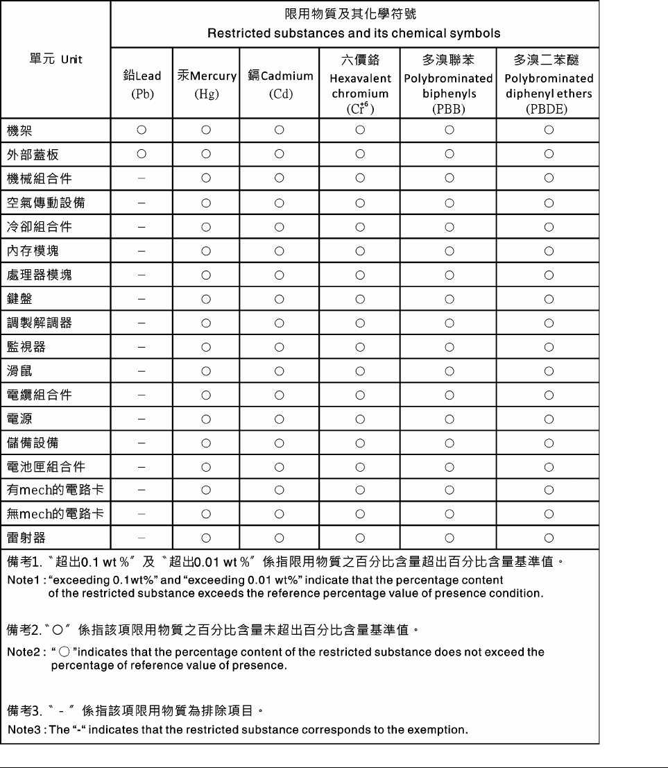
Taiwan BSMI RoHS declaration
Taiwan import and export contact information
Contacts are available for Taiwan import and export information.
206
XClarity Controller with Intel Xeon SP (1st, 2nd Gen)User's Guide

208 XClarity Controller with Intel Xeon SP (1st, 2nd Gen)User's Guide

Index
A
absolute mouse control 64
accseccfg command 107
activation key
export 86
install 85, 122
manage 122
remove 86, 122
Active Directory Users
LDAP 149
active system events
overview 47
adapter command 168
adapter information
Server Configuration 55
advanced Ethernet
settings 29, 174
advanced management module 1
Agent-less commands 159
alertcfg command 108
alertentries command 154
alphabetical command list 91
asu command 109
audit log 51
autonegotiation
set 119
B
backup command 112
baseboard management controller (BMC) 1
batch command 156
binding method
LDAP server 123
BIOS (basic input/output system) 1
block list and time restriction
settings 34
blue screen capture 63
BMC
certificate signing request 40
BMC management
BMC configuration
back up BMC configuration 45
backup and restore BMC configuration 45
restore BMC configuration 46
restore to factory default 46
browser requirements 6
C
CA-signed
certificate 40
centralized management
encryption keys 39
certificate classifications
CA-signed 40
self-assigned 40
certificate management
CIM over HTTPS 139–140
client 40
Drive Access 143
HTTPS server 139–140
LDAP 139–140
server 43
SSH server 138
certificate signing request
BMC 40
CIM over HTTP port
set 128
CIM over HTTPS
certificate management 139–140
security 139–140
CIM over HTTPS port
set 128
clearcfg command 157
clearlog command 94
CLI key sequence
set 126
client
certificate management 40
client certificate management
CA-signed 40
self-assigned 40
client distinguished name
LDAP server 123
clock command 157
collecting service data 75, 200
command-line interface (CLI)
accessing 89
command syntax 90
description 89
features and limitations 90
logging in 89
commands
accseccfg 107
adapter 168
alertcfg 108
alertentries 154
asu 109
backup 112
batch 156
clearcfg 157
clearlog 94
clock 157
console 107
dbgshimm 171
dhcpinfo 113
dns 114
encaps 116
ethtousb 116
exit 93
fans 95
ffdc 95
firewall 117
fuelg 105
gprofile 118
hashpw 118
help 93
history 93
hreport 96
identify 158
ifconfig 119
info 158
keycfg 122
ldap 123
led 97
m2raid 170
mhlog 97
ntp 125
portcfg 126
portcontrol 127
ports 128
power 102
pxeboot 106
© Copyright Lenovo 2017, 2022
209
rdmount 129
readlog 99
reset 104
restore 130
restoredefaults 130
roles 131
seccfg 132
set 132
smtp 133
snmp 133
snmpalerts 135
spreset 159
srcfg 137
sshcfg 138
ssl 139
sslcfg 140
storage 159
storekeycfg 143
syncrep 144
syshealth 100
temps 101
thermal 145
timeouts 146
TLS 147
trespass 147
uefipw 148
usbeth 149
usbfp 149
users 149
volts 101
vpd 102
commands, alphabetical list 91
commands, types of
Agent-less 159
configuration 107
IMM control 154
monitor 94
serial redirect 107
server power and restart 102
Support 171
utility 93
configuration commands 107
configuration restore
IMM 130
configure
block list and time restriction 34
DDNS 114
DDNS settings 31
DNS 114
DNS settings 31
Ethernet 119
Ethernet over USB 116
Ethernet over USB settings 32
Ethernet settings 29, 174
IPMI 33
IPMI over KCS Access 38
IPv4 119
IPv6 119
LDAP 123
LDAP server 123
LDAP settings 24
network protocols 29
network service port 127
port assignments 33
ports 128
prevent system firmware down-level 39
security settings 36
serial port 126
SKLM device group 40
SKLM key repository servers 40
SMTP 133
SNMPv1 133
SNMPv1 traps 133
SNMPv3 alert settings 32
SNMPv3 user accounts 149
SSH server 38
USB 116
user account security levels 107
configuring
front panel USB port to management 35
global login settings 22
serial-to-SSH redirection 89
configuring the server
options to configure
the server 55
configuring the storage
options to configure
the storage 79
configuring the XClarity Controller
options to configure
the XClarity Controller 17
console command 107
contamination, particulate and gaseous 204
create
user account 149
creating a personalized support web page 199
Cryptography Setting
Cryptography Setting 43
custom support web page 199
D
date
set 157
date and time, XClarity Controller
setting 77
dbgshimm command 171
dcmi
functions and commands 60
power management 60
DDNS
configure 114
custom domain name 114
DHCP server specified domain name 114
domain name source 114
manage 114
default configuration
IMM 130
default static IP address 10
delete
user 149
delete group
enable, disable 118
device group
drive access page 40
dhcpinfo command 113
distinguished name, client
LDAP server 123
distinguished name, root
LDAP server 123
DNS
configure 114
IPv4 addressing 114
IPv6 addressing 114
LDAP server 123
server addressing 114
dns command 114
domain name source
DDNS 114
domain name, custom
DDNS 114
domain name, DHCP server specified
DDNS 114
Drive Access
certificate management 143
security 143
drive access page
configure 40
210 XClarity Controller with Intel Xeon SP (1st, 2nd Gen)User's Guide
device group 40
key management servers 40
SKLM certificate management 40
Drive Access tab
security option 39–40
E
email and syslog notifications 52
encaps command 116
encryption keys
centralized management 39
enhanced role-based security
LDAP 149
enterprise level features 5
Ethernet
configure 119
Ethernet over USB
configure 116
port forwarding 116
ethtousb command 116
event log 51
event window
log 51
exit command 93
exiting the remote console session 75
export
activation key 86
Extended Audit Log
extended audit log 43
F
fans command 95
features of XClarity Controller 2
Features on Demand
install feature 122
manage 122
remove feature 122
ffdc command 95
firewall command 117
firmware
view server 102
firmware, server
updating 83
Flex servers 1
Flex System 1
FoD
install feature 122
manage 122
remove feature 122
fuelg command 105
functions and commands
dcmi 60
node manager 59
G
gaseous contamination 204
Getting help 199
global login
settings 22
global login settings
account security policy settings 23
gprofile command 118
group filter
LDAP 123
group search attribute
LDAP 123
H
hardware health 47
hardware service and support telephone numbers 201
hash password 20
hashpw command 118
help 199
help command 93
history command 93
host name
LDAP server 123
set 119
SMTP server 133
hreport command 96
HTTP port
set 128
HTTPS port
set 128
HTTPS server
certificate management 139–140
security 139–140
I
identify command 158
ifconfig command 119
IMM
configuration restore 130
default configuration 130
reset 159
reset configuration 130
restore configuration 130
spreset 159
IMM control commands 154
important notices 204
info command 158
install
activation key 85, 122
install feature
Features on Demand 122
FoD 122
IP address
configuring 9
IPv4 9
IPv6 9
LDAP server 123
SMTP server 133
IP address, default static 10
IPMI
configure 33
remote server management 173
ipmi bridging
power management 59
through XClarity Controller 59
ipmi commands
power consumption 59
IPMI interface
description 173
IPMI over KCS Access
configure 38
IPMItool 173
IPv4
configure 119
IPv4 addressing
DNS 114
IPv6 9
configure 119
IPv6 addressing
DNS 114
© Copyright Lenovo 2017, 2022
211
K
key management servers
configure 40
drive access page 40
keyboard support in remote console 63
keycfg command 122
L
LDAP
Active Directory Users 149
certificate management 139–140
configure 123
configuring 17
enhanced role-based security 149
group filter 123
group search attribute 123
login permission attribute 123
role-based security, enhanced 149
security 139–140
server target name 123
ldap command 123
LDAP server
binding method 123
client distinguished name 123
configure 123
DNS 123
host name 123
IP address 123
password 123
port number 123
pre-configured 123
root distinguished name 123
search domain 123
UID search attribute 123
LDAP server port
set 123
led command 97
License Management 85
logging in to the XClarity Controller 12
login attempt authentication 17
login permission attribute
LDAP 123
M
m2raid command 170
MAC address
manage 119
maintenance history 52
manage
activation key 122
DDNS 114
Features on Demand 122
FoD 122
MAC address 119
SNMPv1 communities 133
user 149
management
server certificate 43
SKLM certificate 40
managing power
using IPMI commands 59
maximum transmission unit
set 119
media mount error issues 73
media mount methods 65
mhlog command 97
MIBs Introduction 7
minimum, levels
TLS 147
monitor commands 94
monitoring power
using IPMI commands 59
monitoring the server status 47
mouse control
absolute 64
relative 64
relative with default Linux acceleration 64
mouse support in remote console 64
MTU
set 119
multiple language support 7
N
network connection 10
default static IP address 10
IP address, default static 10
static IP address, default 10
network protocol properties
assert physical presence 39
block list and time restriction 34
DDNS 31
DNS 31
Ethernet over USB 32
Ethernet settings 29, 174
IPMI 33
IPMI over KCS Access 38
port assignments 33
prevent system firmware down-level 39
SNMP alert settings 32
network service port
configure 127
network settings
IPMI commands 33
new local account
creating 18
node manager
functions and commands 59
notes, important 204
notices 203
notices and statements 8
ntp command 125
O
OEM IPMI Commands 185
one-time
setting up 56
OneCLI 1
online publications
documentation update information 1
error code information 1
firmware update information 1
operating-system requirements 6
operating-system screen capture 63
option
SKM 39
OS failure screen data
capture 54
overview 47
ssl 36
P
particulate contamination 204
password
LDAP server 123
user 149
port assignments
212 XClarity Controller with Intel Xeon SP (1st, 2nd Gen)User's Guide
configure 33
settings 33
port forwarding
Ethernet over USB 116
port number
LDAP server 123
SMTP server 133
port numbers
set 128
portcfg command 126
portcontrol command 127
ports
configure 128
set numbers 128
view open 128
ports command 128
power
managing using IPMI commands 59
monitoring using IPMI commands 59
power command 102
power consumption
ipmi commands 59
power management
dcmi 60
ipmi bridging 59
power management option
power actions 58
power capping policy 57
power redundancy 57
power restore policy 58
Server Management tab 57
pre-configured
LDAP server 123
prevent system firmware down-level
configure 39
pxeboot command 106
R
RAID detail
Server Configuration 79
RAID setup
Server Configuration 79
rdmount command 129
readlog command 99
relative mouse control 64
relative mouse control for Linux (default Linux acceleration) 64
remote access 2
remote console
absolute mouse control 64
keyboard support 63
mouse support 64
power and restart commands 62
relative mouse control 64
relative mouse control for Linux (default Linux
acceleration) 64
screen capture 63
video viewer 61
virtual media session 61
remote console feature 61
remote console functionality 61
enabling 62
remote console mouse support 64
remote console port
set 128
remote console screen modes 65
remote power control 62
remove
activation key 86, 122
remove feature
Features on Demand 122
FoD 122
requirements
operating system 6
web browser 6
reset
IMM 159
reset command 104
reset configuration
IMM 130
restart XClarity Controller 46
restore command 130
restore configuration
IMM 130
restoredefaults command 130
role-based levels
operator 118
rbs 118
supervisor 118
role-based security, enhanced
LDAP 149
roles command 131
root distinguished name
LDAP server 123
S
screen video record/replay
server management 64
search domain
LDAP server 123
seccfg command 132
security
CIM over HTTPS 139–140
Drive Access 143
HTTPS server 139–140
LDAP 139–140
SSH server 38, 138
ssl certificate handling 37
SSL certificate management 37
ssl overview 36
security option
Drive Access tab 39–40
Security option
Drive Access tab 40
self-assigned
certificate 40
Serial over LAN 173
serial port
configure 126
serial redirect command 107
serial-to-SSH redirection 89
server
certificate management 43
configuration options 55
server addressing
DNS 114
server certificate
management 43
server configuration
server properties 75
Server Configuration
adapter information 55
RAID detail 79
RAID setup 79
server firmware
updating 83
server management
one-time 56
OS failure screen data 54
screen video record/replay 64
server firmware 83
server timeouts, setting 76
system boot mode 55
system boot order 55
Server Management tab
© Copyright Lenovo 2017, 2022
213
power management option 57
server power and restart
commands 102
server properties
server configuration 75
setting location and contact 75
server status
monitoring 47
server target name
LDAP 123
server timeout
selections 76
service and support
before you call 199
hardware 201
software 201
service data 200
collecting 75
downloading 75
set
autonegotiation 119
CIM over HTTP port 128
CIM over HTTPS port 128
CLI key sequence 126
date 157
host name 119
HTTP port 128
HTTPS port 128
LDAP server port 123
maximum transmission unit 119
MTU 119
remote console port 128
SNMP agent port 128
SNMP Traps port 128
SNMPv1 contact 133
SNMPv3 contact 133
SSH CLI port 128
time 157
user authentication method 107
web inactivity timeout 107
set command 132
set port numbers 128
setting
the XClarity Controller date and time 77
setting location and contact 75
setting server timeouts 76
settings
advanced 29, 174
block list and time restriction 34
DDNS 31
DNS 31
Ethernet 29, 174
Ethernet over USB 32
global login 22
account security policy settings 23
LDAP 24
port assignments 33
security 36
SNMP alert 32
SSH server 38
SKLM
key management servers 40
SKLM certificate
management 40
SKLM certificate management
drive access page 40
SKLM device group
configuration 40
SKM
option 39
SMTP
configure 133
server host name 133
server IP address 133
server port number 133
smtp command 133
SNMP agent port
set 128
snmp command 133
SNMP TRAP recipients 52
SNMP Traps port
set 128
snmpalerts command 135
SNMPv1
configure 133
SNMPv1 communities
manage 133
SNMPv1 contact
set 133
SNMPv1 traps
configure 133
SNMPv3 contact
set 133
SNMPv3 settings
user 149
SNMPv3 user accounts
configure 149
software service and support telephone numbers 201
spreset command 159
srcfg command 137
SSH CLI port
set 128
SSH keys
user 149
SSH server
certificate management 138
security 138
sshcfg command 138
SSL
certificate handling 37
certificate management 37
ssl command 139
sslcfg command 140
standard level features 2
static IP address, default 10
storage
configuration options 79
storage command 159
storage devices 159
storage devices
storage command 159
storage inventory 80
storekeycfg command 143
Support commands 171
support for multiple languages 7
support web page, custom 199
syncrep command 144
syshealth command 100
system information 48
system utilization 50
T
Taiwan BSMI RoHS declaration 206
Taiwan import and export contact information 206
target name, server
LDAP 123
telecommunication regulatory statement 205
telephone numbers 201
temps command 101
the system information
viewing 48
the system utilization
viewing 50
thermal command 145
ThinkSystem Server Firmware
description 1
time
214 XClarity Controller with Intel Xeon SP (1st, 2nd Gen)User's Guide
set 157
timeouts command 146
TLS
minimum level 147
TLS command 147
tools
IPMItool 173
trademarks 204
trespass command 147
trespass message option 76
U
uefipw command 148
UID search attribute
LDAP server 123
USB
configure 116
usbeth command 149
usbfp command 149
user
delete 149
manage 149
password 149
SNMPv3 settings 149
SSH keys 149
user account
create 149
deleting 20
user account security levels
configure 107
user authentication method 17
set 107
users
view current 149
users command 149
using
remote console feature 61
remote console function 61
utility commands 93
V
Video Viewer
absolute mouse control 64
mouse support 64
power and restart commands 62
relative mouse control 64
relative mouse control for Linux (default Linux
acceleration) 64
screen capture 63
video color mode 63
view and configure the virtual drives 79
view current
users 149
view firmware information
server 102
view open ports 128
volts command 101
vpd command 102
W
Web browser requirements 6
web inactivity session timeout 23
web inactivity timeout
set 107
web interface
logging in to web interface 12
web interface, opening and using 9
working with
events in the audit log 51
events in the event log 51
X
XClarity Controller
configuration options 17
configure network protocol 29
description 1
features 2
ipmi bridging 59
network connection 10
new functions 1
serial redirection 89
web interface 9
XClarity Controller advanced level 2
XClarity Controller enterprise level 2
XClarity Controller standard level 2
XClarity Controller features
enterprise level 5
standard level 2
XClarity Controller features advanced level features
advanced level 5
XClarity Controller functions
on web interface 13
XClarity Controller management
configuring LDAP 17
configuring user accounts 17
creating a new local user 18
deleting a user account 20
security settings 36
XClarity Controller properties
date and time 77
XClarity Provisioning Manager
Setup utility 10
© Copyright Lenovo 2017, 2022
215
216 XClarity Controller with Intel Xeon SP (1st, 2nd Gen)User's Guide

Part Number: SP47A30085
Printed in China
(1P) P/N: SP47A30085
*1PSP47A30085*
