
Reference Manual | Edition 9.0 (03-2021) |
S.ON
1 | 214
S.ON
Wire Processing Software for MultiStrip 9480
Reference Manual
Software Version 8.1x |Edition 9.0 (03-2021)

Address / distributors
2 | 214
Reference Manual | Edition 9.0 (03-2021) |
S.ON
Schleuniger AG
Bierigutstrasse 9
3608 Thun
Switzerland
P +41 (0)33 334 03 33
F +41 (0)33 334 03 34
info@schleuniger.ch
www.schleuniger.com
Schleuniger AG
Gewerbestrasse 14
6314 Unteraegeri
Switzerland
P +41 (0)41 754 53 53
F +41 (0)41 754 53 50
solutions@schleuniger.ch
www.schleuniger.com
Schleuniger GmbH
Raieisenstrasse 14
42477 Radevormwald
Germany
P +49 (0)21 959 29-0
F +49 (0)21 959 29-105
info@schleuniger.de
www.schleuniger.com
Schleuniger Test Automation GmbH
Steinung 3.1
71131 Jettingen
Germany
P +49 74 52 74 062 80
F +49 74 52 74 062 90
info.testaut[email protected]om
www.schleuniger.com
Schleuniger, Inc.
87 Colin Drive
Manchester, NH 03103
USA
P +1 (603) 668 81 17
F +1 (603) 668 81 19
sales@schleuniger.com
www.schleuniger-na.com
Schleuniger Japan Co., Ltd.
1726-15, Higashi-Naganuma,
Inagi-city, Tokyo
Japan
P +81 42 401 6581
F +81 42 379 3524
sales@schleuniger.co.jp
www.schleuniger.co.jp
Schleuniger Trading (Shanghai) Co., Ltd.
108, BH Center
7755 Zhongchun Rd
Shanghai, 201101
China
P +86 (21) 62 52 66 77
F +86 (21) 62 40 86 55
sales@schleuniger.com.cn
www.schleuniger.cn
Schleuniger Machinery (Tianjin) Co., Ltd.
A-101 & B-101, D9 Building, No 1 Xuefu West Road,
Xuefu Industrial Zone
Xiqing Qu, Tianjin Shi 300392
China
P +86 (22) 8371 3090
salesstj@schleuniger.com.cn
www.schleuniger.cn
Original Instructions
The German edition of this document is the original Instructions.
Translation of the original Instructions
All non German language editions of this document are translations of the original Instructions.
© 2021 Schleuniger | ID-0000000182-017-EN
Product variant: MultiStrip 9480 |

Topic list
Reference Manual | Edition 9.0 (03-2021) |
S.ON
3 | 214
TOPIC LIST
ADDRESSES
▶ www.schleuniger.com
▶ info@schleuniger.ch
▶ Page 2
Web site for our products, manufacturer address and distributors, email
addresses.
GUIDELINES / SAFETY
▶ Page 11
General information about this manual, warranty statements and policies,
sources of danger (symbols).
PRODUCT OVERVIEW
▶ Page 17
▶ Page 19
▶ Page 21
An overview to the architecture of the software, technical data and optional
features.
INSTALLATION / FIRST USE
▶ Page 27
Step by step instruction for installing and commissioning the software.
OPERATION
▶ Page 29
▶ Page 59
▶ Page 95
▶ Page 111
▶ Page 117
Detailed description (reference part) for operating the touch screen.
CONFIGURATION
▶ Page 123
▶ Page 147
Conguration of screens and pre-settings of S.ON.
DIAGNOSTICS / TROUBLESHOOTING
▶ Page 151
Software diagnostics for S.ON and the to be connected wire processing
machine, localization of faults, software versions, software update.
DATA MANAGEMENT / SOFTWARE UPGRADE
▶ Page 161
Data backup and -restore of article data, software upgrade, data logging.
PROGRAMMING EXAMPLES
▶ Page 169
Simple programming- and application examples for the beginner.

Topic list
4 | 214
Reference Manual | Edition 9.0 (03-2021) |
S.ON

Table of contents
Reference Manual | Edition 9.0 (03-2021) |
S.ON
5 | 214
TABLE OF CONTENTS
1
GENERAL 11
1.1
MANUFACTURER ............................................................11
1.2
PRODUCT TYPE .............................................................11
1.3
INFORMATION ABOUT THE OPERATING INSTRUCTIONS ..........................11
1.3.1 Contents.................................................................... 11
1.3.2 Safekeeping.................................................................. 12
1.4
SYMBOLS .................................................................. 12
1.5
LEGEND ....................................................................13
1.6
LIMITATION OF LIABILITY .....................................................13
1.7
WARRANTY STATEMENTS AND POLICIES .......................................14
1.8
COPYRIGHT PROTECTION ....................................................14
1.8.1 Trademarks.................................................................. 14
2
SAFETY 15
2.1
TARGET AUDIENCES .........................................................15
2.2
WARNING NOTICES ..........................................................16
2.3
CAUTION PROPERTY DAMAGE ................................................16
2.4
MODIFICATION OF THE SOFTWARE ............................................16
3
PRODUCT SPECIFICATIONS 17
3.1
APPLICATION PURPOSE ......................................................17
3.1.1 Intended usage of product....................................................... 17
3.2
TECHNICAL SPECIFICATIONS ................................................. 17
4
PRODUCT DESCRIPTION 19
4.1
THE MAIN APPLICATIONS ....................................................19
5
SCHLEUNIGER WIRE PROCESSING CONCEPT 21
5.1
STANDARD PROCESS FLOW ..................................................22
5.2
LIBRARY MODE ............................................................. 23
5.3
ARTICLE LIST MODE .........................................................24
5.3.1 Additional properties in the “Article list mode”........................................ 25
6
INSTALLATION / FIRST COMMISSIONING 27
6.1
SAFETY INSTRUCTIONS ......................................................27
6.2
GENERAL SOFTWARE SETUP ..................................................27
7
GENERAL HANDLING / OPERATION 29
7.1
VISUAL REPRESENTATION OF THE OPERATING ELEMENTS AND PICTOGRAMS ......29
7.2
GENERAL MEASURING GUIDELINES ........................................... 29

Table of contents
6 | 214
Reference Manual | Edition 9.0 (03-2021) |
S.ON
7.3
QUICK INFO ................................................................ 29
7.4
TOUCH SCREEN .............................................................30
7.4.1 Header line................................................................... 30
7.4.2 Info / machine status........................................................... 30
7.4.3 Content area................................................................. 31
7.4.4 Footer area................................................................... 31
7.5
MAIN CONTROLS ............................................................32
7.5.1 Navigation................................................................... 32
7.5.2 Production................................................................... 36
7.6
KEYS / COMMANDS / PICTOGRAMS ........................................... 38
7.6.1 Toggle key / entry eld.......................................................... 38
7.6.2 Drop-down list................................................................ 39
7.6.3 Spin box / numeric touch keyboard................................................. 39
7.6.4 Alphanumeric touch-keyboard.................................................... 40
7.6.5 Special entry elds and functions.................................................. 41
7.6.6 Dialog window................................................................ 42
7.6.7 Lists and libraries.............................................................. 42
7.7
DATA MANAGEMENT ........................................................43
7.7.1 Overview.................................................................... 44
7.7.2 Description................................................................... 44
7.7.3 File name convention........................................................... 46
7.8
SAVING ARTICLE ............................................................ 46
7.8.1 Save........................................................................ 47
7.8.2 Save as........................................................................ 47
7.8.3 Cancel changes............................................................... 47
7.9
SHOW ARTICLE ............................................................. 47
7.10
SETUP OF VIEWS AND MODES ................................................48
7.10.1 Toggle measuring mode / correction mode........................................... 48
7.11
ENHANCED FUNCTIONS .....................................................49
7.11.1 “SmartDetect”................................................................ 49
7.11.2 Sensitivity correction........................................................... 51
7.11.3 Disposal of rejected pieces....................................................... 51
7.11.4 Manual declaration of rejected pieces............................................... 54
7.11.5 CAYMAN-Support.............................................................. 57
7.11.6 Load le with barcode scanner.................................................... 57
8
STANDARD PROCESS FLOW 59
8.1
PRINCIPAL “STANDARD PROCESS FLOW” .......................................59
8.2
SINGLE ARTICLE EDITOR OVERVIEW ...........................................60
8.3
SINGLE ARTICLE EDITOR DESCRIPTION .........................................61
8.3.1 Init......................................................................... 61
8.3.2 Processing................................................................... 61
8.3.3 Wire length.................................................................. 61
8.3.4 End application left / right....................................................... 62
8.3.5 Area application............................................................... 63
8.3.6 Swapping areas............................................................... 63
8.3.7 Activate area................................................................. 63
8.3.8 Rejected pieces............................................................... 63
8.3.9 Declare rejects................................................................ 63
8.3.10 Ignore rejects................................................................. 63
8.3.11 Reset production counter........................................................ 63

Table of contents
Reference Manual | Edition 9.0 (03-2021) |
S.ON
7 | 214
8.3.12 Remaining batch size........................................................... 63
8.3.13 Batch size.................................................................... 64
8.3.14 Activate batch................................................................ 64
8.3.15 Remaining articles............................................................. 64
8.3.16 Produced articles.............................................................. 64
8.3.17 Quantity..................................................................... 64
8.3.18 Remarks / messages............................................................ 64
8.4
SINGLE ARTICLE EDITOR FURTHER SCREENS ....................................64
8.5
PROCESSING EDITOR ........................................................65
8.5.1 General overview.............................................................. 65
8.5.2 Default...................................................................... 66
8.5.3 Elements.................................................................... 67
8.5.4 Feed........................................................................ 70
8.5.5 Cut......................................................................... 72
8.5.6 Options..................................................................... 74
8.5.7 Rotary incising unit............................................................. 78
8.5.8 Comment.................................................................... 79
8.6
APPLICATION EDITOR ........................................................79
8.6.1 Overview.................................................................... 79
8.6.2 Description................................................................... 79
8.6.3 Partial- and full strip............................................................ 80
8.6.4 Window strip................................................................. 80
8.6.5 Multi layer cable............................................................... 80
8.6.6 Multi conductor cable........................................................... 81
8.6.7 Flat ribbon cable............................................................... 81
8.7
APPLICATION EDITOR AREA ..................................................82
8.7.1 Screen overview............................................................... 82
8.7.2 Area settings................................................................. 83
8.8
RAW MATERIAL EDITOR ......................................................87
8.8.1 Overview of standard Raw Materials................................................ 87
8.9
INIT ........................................................................89
8.9.1 Convert to library.............................................................. 89
8.9.2 Raw material- / Processing data................................................... 90
8.9.3 Application left / right........................................................... 90
8.9.4 Swap application left/right....................................................... 90
8.9.5 Wire dimension............................................................... 91
8.9.6 Raw material type.............................................................. 91
8.9.7 Single article - creation type...................................................... 91
8.10
AUTONOMOUS PROCESSING ELEMENT ........................................92
8.11
RECALCULATION DEFAULT VALUES ............................................93
9
LIBRARY MODE 95
9.1
ACTIVATING LIBRARY MODE ..................................................95
9.2
CREATE NEW ARTICLE ........................................................96
9.2.1 Convert an existing article....................................................... 96
9.2.2 Link new / existing article with library data sets........................................ 96
9.3
SINGLE ARTICLE EDITOR IN THE LIBRARY MODE ................................ 97
9.4
RAW MATERIAL LIBRARY .....................................................98
9.4.1 Raw material library, list view..................................................... 98
9.4.2 Raw material editor............................................................ 99
9.4.3 Raw material selection in the "Init" screen........................................... 101

Table of contents
8 | 214
Reference Manual | Edition 9.0 (03-2021) |
S.ON
9.5
PROCESSING LIBRARY ...................................................... 102
9.5.1 Processing library list view...................................................... 102
9.5.2 Processing editor............................................................. 102
9.5.3 Processing selection in the "Init" screen............................................. 103
9.6
APPLICATIONS .............................................................104
9.6.1 Predened.................................................................. 104
9.6.2 User dened................................................................. 104
9.6.3 Layer sectioning on complex wires................................................ 105
9.6.4 Application editor............................................................. 105
10
ARTICLE LIST MODE 111
10.1
LIST VIEW ................................................................. 112
10.2
ARTICLE LIST PRODUCTION ................................................. 112
10.3
ARTICLE PROGRAMMING ....................................................113
10.4
PRODUCTION SETTINGS ....................................................113
10.4.1 Production.................................................................. 113
10.4.2 General.................................................................... 114
10.4.3 Stop conditions.............................................................. 115
10.5
RESET PRODUCTION COUNTER ..............................................116
10.6
ADD NEW FILE / FILE FROM LIBRARY ..........................................116
10.7
OPTIONS SELECTED FILES ...................................................116
10.8
PRODUCTION RELEASE .....................................................116
11
PRODUCTION 117
11.1
LOAD RAW MATERIAL .......................................................117
11.1.1 Normal loading with [LOAD] .................................................... 117
11.1.2 Alternative loading with [CLOSE] ................................................. 117
11.2
UNLOADING RAW MATERIAL ................................................ 117
11.2.1 Normal unloading with [UNLOAD] ................................................ 117
11.2.2 Unloading with [OPEN] ........................................................ 117
11.3
RELOADING RAW MATERIAL .................................................118
11.3.1 Method A................................................................... 118
11.3.2 Method B................................................................... 118
11.4
OPERATION OF THE RECOIL BRAKE ...........................................119
11.4.1 Loading procedure............................................................ 119
11.4.2 Unloading procedure.......................................................... 119
11.5
START PRODUCTION ........................................................119
11.5.1 Series production with [START] .................................................. 119
11.5.2 Production with [SINGLE] ...................................................... 119
11.5.3 Production in step by step- / speed control mode with [MODE] .......................... 120
11.6
FURTHER COMMANDS / STATUS MESSAGES ...................................120
11.6.1 Production screen............................................................. 120
11.6.2 Messages during start-up....................................................... 122
11.6.3 Messages during the production.................................................. 122
12
CONFIGURATION SETTINGS 123
12.1
SETUP VERSUS CONFIGURATION .............................................123

Table of contents
Reference Manual | Edition 9.0 (03-2021) |
S.ON
9 | 214
12.2
CALIBRATE ................................................................ 124
12.3
SETUP .....................................................................124
12.3.1 PreFeeder................................................................... 125
12.3.2 Blade settings- / change / cartridge selection........................................ 125
12.3.3 Feed....................................................................... 125
12.3.4 Post processing device......................................................... 125
12.4
CONFIGURATION ...........................................................126
12.4.1 Marking.................................................................... 127
12.4.2 Machine.................................................................... 128
12.4.3 Cartridge selection / blade conguration / blade change................................ 134
12.4.4 User dened device........................................................... 137
12.4.5 Monitoring.................................................................. 137
12.4.6 Post-processing.............................................................. 138
12.4.7 Production settings........................................................... 139
12.4.8 Clock...................................................................... 140
12.4.9 Quality Assurance............................................................. 140
12.4.10 Conguration export as screenshots............................................... 140
12.4.11 Conguration export as text le.................................................. 140
12.4.12 Export conguration........................................................... 141
12.4.13 Import the actual conguration data............................................... 141
12.5
EXTENDED SETTINGS FOR PERIPHERAL DEVICES ...............................141
12.5.1 Without post processing - properties.............................................. 141
12.5.2 WireStacker - properties........................................................ 142
12.5.3 Additional properties with active wire stacker........................................ 144
12.5.4 CableCoiler - properties........................................................ 145
12.5.5 Programming................................................................ 145
13
USER INTERFACE / USER LEVELS 147
13.1
SCREEN OVERVIEW .........................................................147
13.2
USER INTERFACE ...........................................................147
13.3
USER LEVEL ................................................................148
13.4
USER LEVEL RESTRICTIONS ..................................................150
14
DIAGNOSTICS / TROUBLESHOOTING 151
14.1
DIAGNOSTICS "MACHINE" ...................................................151
14.1.1 Components................................................................ 151
14.1.2 Electric platform.............................................................. 156
14.1.3 Interfaces................................................................... 156
14.1.4 Operating unit............................................................... 156
14.1.5 Peripheral interfaces........................................................... 156
14.1.6 Operating status.............................................................. 157
14.1.7 Operating data............................................................... 157
14.1.8 Hardware................................................................... 157
14.1.9 Software.................................................................... 158
14.2
MESSAGES ................................................................ 158
14.2.1 Warning.................................................................... 158
14.2.2 Error....................................................................... 159
14.2.3 Error message protocols........................................................ 159
15
DATA MANAGEMENT / UPGRADES / SERVICES 161
15.1
SERVICES ..................................................................161

Table of contents
10 | 214
Reference Manual | Edition 9.0 (03-2021) |
S.ON
15.1.1 Main screen................................................................. 161
15.1.2 Backup..................................................................... 162
15.1.3 Logging.................................................................... 163
15.1.4 File conversion............................................................... 163
15.1.5 Software upgrade............................................................. 164
16
PROGRAMMING TIPS / EXAMPLES 169
17
APPENDIX 171
17.1
OVERVIEW OF SYMBOLS ....................................................171
17.1.1 Main screens (navigation)....................................................... 171
17.1.2 Production commands......................................................... 171
17.1.3 Global header- and footer line commands........................................... 172
17.1.4 Article editor................................................................ 172
17.1.5 Toggle mode................................................................ 172
17.1.6 List commands............................................................... 173
17.2
TIME / DATE FORMATS ......................................................173
17.2.1 Time formats................................................................ 173
17.2.2 Date formats................................................................. 173
17.3
EXTERNAL KEYBOARD ON THE USB CONNECTOR ..............................174
17.3.1 Key assignment.............................................................. 175
17.4
LICENSES ..................................................................175
17.4.1 License info in the About... Screen................................................. 175
17.4.2 Pugixml.................................................................... 175
17.4.3 Qt Framework 5.3............................................................. 176
17.4.4 LGPL 2.1 License.............................................................. 176
17.4.5 Schleuniger written oer for LGPL source code........................................ 182
17.4.6 Third-Party Licenses Used in Qt................................................... 182
17.5
TABLE OF GRAPHICS ........................................................206
17.6
TABLE OF CHARTS ..........................................................206
INDEX 209

1. General
Reference Manual | Edition 9.0 (03-2021) |
S.ON
11 | 214
GENERAL
Thank you for your trust in the Schleuniger Technique. You have acquired a high performance Schleu-
niger product, designed and manufactured in our factory to your needs.
Read through this manual with due care and attention. It contains important tips and safety instruc-
tions, which allow precise and reliable production.
1.1
MANUFACTURER
In this Manual, Schleuniger AG Thun, Switzerland is referred to as manufacturer and abbreviated with
„Schleuniger“.
Schleuniger AG Phone: +41 (0)33 334 03 33
Bierigutstrasse 9 Fax: +41 (0)33 334 03 33
3608 Thun E-mail: info@schleuniger.ch
Switzerland Web: www.schleuniger.com
1.2
PRODUCT TYPE
This manual is valid for the following products/models:
S.ON Wire processing software for MultiStrip 9480
The applicable product type and the manufacture year can be found on the rating plate or the EG
declaration of conformity. See “EU-Declaration of Conformity (Register 2)“ of the ring binder.
1.3
INFORMATION ABOUT THE OPERATING INSTRUCTIONS
We have taken every possible measures to ensure the accuracy and completeness of this documenta-
tion. Since errors can be avoided despite the diligence never fully, we are always grateful for any
advice and suggestions.
This manual is stated as "Operating Instructions" and is part of the product. It contains all informa-
tion to operate the machine eciently and safely.
Observe the safety regulations and instructions.
If the product changes hands, the Operating Instruction must be handed over to the new owner.
Published modications and corrections from the manufacturer must be complemented. Inform
at your local Schleuniger distributor.
1.3.1
Contents
General
Each person using the software must be properly trained and have read and understood this Opera-
tor manual. This is also imperative, even when the respective person has operated such a software or
similar software previously and where they have been trained by the manufacturer.
As Operating Instructions we declare:
In printed form the entire content of the folder according to the content table.
On electronic media this Reference manual, the Introduction course and the Quick reference (if
provided).
The manual is no longer valid, if any of its contents (except a Quick reference) are removed or is
changed on the data storage medium.

1. General
12 | 214
Reference Manual | Edition 9.0 (03-2021) |
S.ON
Construction
The Operating Instructions consist of the following parts:
Reference Manual MultiStrip 9480
The Reference Manual contains the complete information for the MultiStrip 9480, operated with S.ON.
It serves as a learning- and general reference work for the personnel.
Contents
Safety
Description of the product
Installation
Operating units
Target audiences
Operator
Qualied personnel
Technical specialists
Reference Manual S.ON
The Reference manual contains all information for operating the S.ON software. It serves as a learning-
and general reference work for the personnel.
Contents
Safety
Description of the product
Schleuniger wire processing concept
Installation
Operating units
Programming
Conguration
Diagnostics
Data management
Target audiences
Operator
Qualied personnel
Technical specialists
1.3.2
Safekeeping
Keep the Operating Instructions nearby of the product and safe against immissions.
The instructions must be available for the operating personnel at all times.
The contents must remain clearly legible beyond the expected lifespan of the product.
1.4
SYMBOLS
The symbols are placed in the marginal notes column and refer to the adjacent text. They have the
following meaning:

1. General
Reference Manual | Edition 9.0 (03-2021) |
S.ON
13 | 214
Symbol Meaning Description
Info Information which helps to operate the product eciently and error-
free.
Overview Detailed description or introductional chapter.
Tip Recommendations and tips which improve the intended utilization
of the product.
Topic Important link.
1.5
LEGEND
In the text, mark-up is used in the following manner.
Markup Meaning Description
[KEY] Key / button Key commands and buttons on screen representa-
tions are in the text shown in squared brackets, capital
letters and orange colored.
„Conguration“ Screen title / menu Screen titles and menus are represented in the text in
"quotation marks".
"1.5 Legend
(Page 13)"
Cross referencing Cross referencing are represented in blue and italic.
1.▹ Activity direction Activity directions are a summary of activity steps
with an arrow.
➥
Consequence of an
activity direction
Results or released actions in activity directions are
represented with a leading arrow.
The following abbreviations are used.
Abbreviation Meaning Description
Fig. Figure Figures are captioned as "Fig.” in the picture title.
Tab. Table Tables are captioned as "Tab."
mm Millimeter All Measures in the manuals are given in millimeters.
CW Clockwise Direction of rotation for a component or an operating
element viewed from rotation axis.
CCW Counter clockwise Direction of rotation for a component or an operating
element viewed from rotation axis.
1.6
LIMITATION OF LIABILITY
The content of these Operating Instructions was put together taking into consideration the current
standards and guidelines according to the state of the technology and our many years of experience.
The manufacturer disclaims any liability for damages and accidents as a result of:
Disregard of the instructions

1. General
14 | 214
Reference Manual | Edition 9.0 (03-2021) |
S.ON
Disregard of safety regulations
Non-intended usage
1.7
WARRANTY STATEMENTS AND POLICIES
See Schleuniger document „General Conditions of Sale and Delivery”.
1.8
COPYRIGHT PROTECTION
Keep this instructions condentially. It is intended for the exclusive use of persons operating the
product. Without written agreement, this instructions shall not be made available to third parties.
The content of the manual in the form of text, illustrations, drawings, circuit diagrams or other presen-
tation, is protected by copyright law of the manufacturer.
1.8.1
Trademarks
The control software S.ON is a trade mark of Schleuniger.
CAYMAN™, the CAYMAN-logo, IGUANA™ and the IGUANA-logo are trademarks of Schleuniger.
The control software S.WOP is a trade mark of Schleuniger.
Windows® is a registered trademark of Microsoft corporation in the USA and other countries.
The rights for other brands and product names in these instructions are deposited by their owners
and must be accepted herewith. Mentioning products not manufactured by Schleuniger is intended
exclusively for information purposes. It does not constitute advertising. Schleuniger is not responsible
in terms of selection, performance or usability of this products. Registered trademarks are not special-
ly marked in these instructions. However, this does not mean that they can be used freely.
See also Chapter "17.4 Licenses (Page 175)".

2. Safety
Reference Manual | Edition 9.0 (03-2021) |
S.ON
15 | 214
SAFETY
2.1
TARGET AUDIENCES
This Operating Instructions is intended for individual target audience. Certain chapters therefore are
withhold for a particular target audience and mentioned accordingly in the introductional section.
Only this group is authorized to carry out the appropriate tasks. The other contents generally is inten-
ded for all audience and is not stated specially.
The product is intended to be operated by persons older than 14 years. Younger persons are not
allowed to operate the product.
The target audiences must have the following skill. Thus have the competence to carry out certain
activities.
Operating company
Qualication
Higher level juristic person
Authority to give directives
Dene competences
Authority / activity
Teaching
Deploy authorized personnel
Use product according to the intended usage
Technical specialists
Technical specialist / service tech-
nician
Produc t-specic training
Know-how in wire processing technics
Authority / activity
Installation
Operating
Programming
Qualied personnel
Qualication
Technical skill
Produc t-specic training
Know-how in wire processing technics
Authority / activity
Operating
Programming
Instructor
Maintenance
Operating personnel
Qualication Produc t-specic training
Authority / activity Operating

2. Safety
16 | 214
Reference Manual | Edition 9.0 (03-2021) |
S.ON
2.2
WARNING NOTICES
The warning notices in the entire manual are marked with the warning banner and the appropriate
danger symbol. The following danger level applies to software products.
CAUTION
Warning notice „Caution"
This hint indicates a potential hazardous situation, which if not avoided, may
result in minor or moderate injury on the MultiStrip 9480 connected to this
software.
Compulsory comply the warning notices to avoid accidents and personnel injury.
2.3
CAUTION PROPERTY DAMAGE
NOTICE
"Property damage"
This panel indicates a hazardous situation, which if not avoided, can result in
damage to property.
2.4
MODIFICATION OF THE SOFTWARE
To avoid any dangerous situations and for an optimal performance, it is not allowed to make any
modications or changes on the product without explicit written permission of the manufacturer or
the local Schleuniger distributor.

3. Product specications
Reference Manual | Edition 9.0 (03-2021) |
S.ON
17 | 214
PRODUCT SPECIFICATIONS
3.1
APPLICATION PURPOSE
3.1.1
Intended usage of product
The product is intended for the following application:
Programming and control of cut o, cut through and stripping processes for cables, wires and
tubes.
See also chapter "4.1 The main applications (Page 19)".
As limits the areas in the technical data apply. Any other use of this product is regarded as non-inten-
ded use. For damages arising therefrom, Schleuniger is not liable.
3.2
TECHNICAL SPECIFICATIONS
Description Value Unit
Storage capacity for arti-
cles
Total memory available for programming.
Approximate memory needed for 1000 arti-
cles (average for mixed applications)
1
3
GB
MB
Operating unit Monitor FPD with touch screen display and
LED background light
5.7 or 10.4 Inch
Resolution 640 x 480 or
1024 x 768
Pixel
Tab. 1: Technical specications

3. Product specications
18 | 214
Reference Manual | Edition 9.0 (03-2021) |
S.ON

4. Product description
Reference Manual | Edition 9.0 (03-2021) |
S.ON
19 | 214
PRODUCT DESCRIPTION
This chapter gives a description of product specications, information on the limits of the product
and points on the scope of delivery. The individual parts are shown and described by photographs.
Further provides the product description information about the functioning and the operation
modes.
S.ON is the operating software for a wide palette of Schleuniger cut & strip machines. Wire program-
ming and production is controlled via a touch screen which is available in dierent models and sizes,
dependent on the machine to be controlled.
The software covers a wide spectrum of applications. The well-arranged screens, operating elements
and pictograms simplies the initial skill adaptation training on understanding the Schleuniger wire
processing concept rigorous.
Libraries for article data, Raw material and Processing.
Assembly of article lists for cable harness and others.
Preset values during programming.
Ecient programming due to pre -dened wire ends.
Visual representation and coloring of the operating elements and pictograms.
Functions for the enhanced programming of complex materials.
Well-arranged conguration with calibration wizards for controlling the MultiStrip 9480.
4.1
THE MAIN APPLICATIONS
Processing capabilities include single wire, multi-conductor cables (Power cords), Coaxial cables, Zip
cords, Plastic optical ber (POF) and many more.
Application Example
Cut to length
Full- or partial strip left and right
Multi-step stripping
Multi-layer stripping
Jacket stripping of multi-cords
Jacket stripping of extremely thin insulations
Jacket- and inner wire stripping
Trim, separate and stripping of individual wires
Cutting back individual conductors (ribbon cables)

4. Product description
20 | 214
Reference Manual | Edition 9.0 (03-2021) |
S.ON
Application Example
Multi-step stripping with slitting and window
Marking of articles
Schleuniger
Schleuniger
5. Schleuniger wire processing concept
Reference Manual | Edition 9.0 (03-2021) |
S.ON
21 | 214
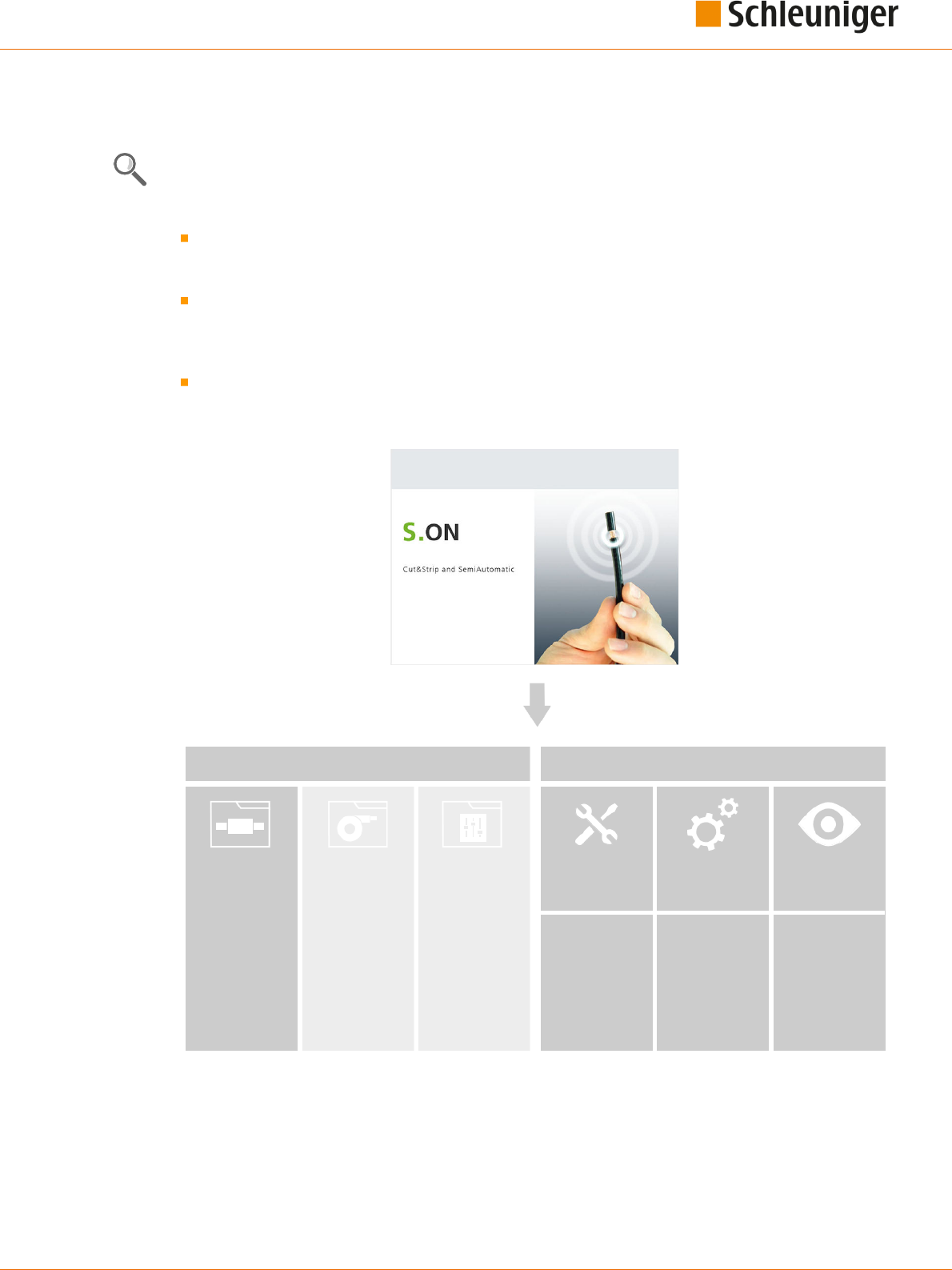
SCHLEUNIGER WIRE PROCESSING CONCEPT
Schleuniger has its own concept for the programming of the MultiStrip 9480.
The design of the software is made user friendly. Graphical representations help making program-
ming articles.
Standard process ow: Orders that slightly vary, for single articles with common operating steps.
Simplied and well-arranged representation of the screens. Adequate for users with none or little
knowledge of programming.
Library mode: Extended programming concept. For lot of individual orders using the same Raw
material and/or Processing or articles that require special processing steps. Settings for the Raw
material and Processing are saved separately in own libraries. They can be assigned individually to
an article.
Article list mode: Processing of article lists. For intense varying orders, containing many or a lot
of single articles. Article lists comprise of individual articles from the article library (e. g. for har-
ness).
Data
Machine
Library
Article
- Single article 1
Library
Raw material
Library
Processing
Setup
Configuration
Diagnostics
- Raw material 1
- Raw material 2
- Raw material 3
- Processing 1
- Processing 2
- Processing 3
- ...
- ...
- Single article 2
- Single article 3
- ...
User
Service
Fig. 1: Wire processing concept, overview

5. Schleuniger wire processing concept
22 | 214
Reference Manual | Edition 9.0 (03-2021) |
S.ON
5.1
STANDARD PROCESS FLOW
The data of the Raw material and the local Processing are saved directly together with the article set-
tings.
Advantage: A single article is programmed quickly. Raw material changes inuence via the adap-
tive default value calculation directly the Processing and as a result the production.
Disadvantage: For each new article of the same type the Raw material and Processing settings
hence must be entered over and over. Changes in the same Raw material and Processing also
must be carried out in every article separately.
Article library
Single article 1
Single article 2
Single article 3
- local -
- local -
- local -
Fig. 2: Overview “Standard process ow”

5. Schleuniger wire processing concept
Reference Manual | Edition 9.0 (03-2021) |
S.ON
23 | 214
5.2
LIBRARY MODE
The "Library mode" nds a remedy for the disadvantages which appear in standard process ow. In
this mode Processing- and Raw material settings are saved in a way that individual articles can use
always the same Raw material and Processing all over again.
All the settings for the Raw material and Processing can be saved in a database. The entered record
then, can be used in dierent articles as often as necessary.
Article library
Linked data
Single article 1
- linked -
Single article 2
- linked -
Single article 3
- linked -
Raw material 1
Raw material 2
Raw material 3
Processing 3
Processing 2
Processing 1
Fig. 3: Overview, „Library mode“
Caution: In the “Library mode”, the adaptive default value calculation from the Raw material is not
available. See Chapter "9 Library mode (Page 95)".

5. Schleuniger wire processing concept
24 | 214
Reference Manual | Edition 9.0 (03-2021) |
S.ON
5.3
ARTICLE LIST MODE
This programming mode is best suited for intense varying orders, containing many or a lot of single
articles. Is often used to produce wiring harnesses.
An article list consists of a list of individual articles programmed in the "Standard processing ow"- or
in "Library mode". The articles are produced one after the other. The article list can be saved as one set
and recalled later for production or for editing the list.
Single article
Article list
Article set 1
Article 1 (from library)
Article 2 (from library)
Article X (from library)
Article set 2
Article set X
Article list 1
Article list 2
Article list X
Fig. 4: Overview, “Article list mode”

5. Schleuniger wire processing concept
Reference Manual | Edition 9.0 (03-2021) |
S.ON
25 | 214
5.3.1
Additional properties in the “Article list mode”
An important advantage of the “Article list mode” is, that the production of an article list is carried out
without slug between the individual articles. The software recalculates the control of wire processing
devices placed before the blades (markers etc.).
Article 1
Article 2
Article 3
Cutting unit
Slug
Wire marker
Automatic cut & strip machine
Fig. 5: Processing without slug
Each article can be dened individually with the same parameters like in the "Standard process ow":
Article name (e. g. the part number used in the company!).
Wire length (total length of a processed article)
Pull-o length (processed length on the ends).
Operation modes (e. g. normal stripping or slitting the jacket in length).
Production quantities (with the ability of breaking down the quantity into several batches)
Name of the Raw material
Name of the Processing

5. Schleuniger wire processing concept
26 | 214
Reference Manual | Edition 9.0 (03-2021) |
S.ON

6. Installation / rst commissioning
Reference Manual | Edition 9.0 (03-2021) |
S.ON
27 | 214
INSTALLATION / FIRST COMMISSIONING
6.1
SAFETY INSTRUCTIONS
CAUTION
While the machine starts up!
Disregarding could lead to injury.
On controlling the MultiStrip 9480, the touch screen on which S.ON is installed,
must be placed directly to the machine.
6.2
GENERAL SOFTWARE SETUP
On the machine there are general settings which must be carried out when putting into operation.
The settings are to be carried out in the screen "Conguration - User - User interface".
1.
▹
[NAVIGATION]
1
2.
▹
[USER]
2
3.
▹
[USER INTERFACE]
3
4.
▹
Select the [LANGUAGE] on the user inter-
face (touch screen)
4
.
5.
▹
Set the country specic [LENGTH UNIT]
5
to „mm“ or „Inch“.
6.
▹
Set the [TIME FORMAT] and the [DATE
FORMAT]
7
on the user interface to the
country specic actuality.
7.
▹
[OK]
8.
▹
NAVIGATION
➥ Back to the article editor.
1
2
3
4
5
6
6

6. Installation / rst commissioning
28 | 214
Reference Manual | Edition 9.0 (03-2021) |
S.ON

7. General handling / operation
Reference Manual | Edition 9.0 (03-2021) |
S.ON
29 | 214
GENERAL HANDLING / OPERATION
The operation of S.ON is described in this and the following chapters in detail (Working in "Simple
mode", " Library mode", "Article list mode" and managing article libraries). All commands, functions
and parameters used for the programming are described step by step. The descriptions in this chap-
ter shall help the user to get an in-depth understanding and shall serve as a reference to handle di-
cult programming tasks. See also Chapter "16 Programming tips / examples (Page 169)".
The corresponding buttons for the commands, functions and the alpha numeric data entry will be
shown directly on the touch screen. A simple touch executes the desired function. Also status mes-
sages show up on the touch screen, depending on the function mode.
Keys and its state and other elements can be distinguished by means of a color scheme.
7.1
VISUAL REPRESENTATION OF THE OPERATING ELEMENTS AND PIC-
TOGRAMS
Labeling of the operating elements and pictograms is depending on the layout on the touch screen
positioned dierently. The function hence is the same.
Most screen representations in this instructions are targeted on the 5.7 Inch display and partially con-
tain the name of the automatic cut & strip machine MultiStrip 9480. However, it is expressly pointed
out, that this also is valid for other display sizes and also for the automatic cut & strip machines Power-
Strip 9550, MegaStrip 9650 and EcoStrip 9380.
Depending on the state of the operating elements they are distinguished with their color and shape:
Key State Key State
Key pressed Key not pressed
Screen selected Screen available
Tab selected Tab available
7.2
GENERAL MEASURING GUIDELINES
The wire length, stripping types and -lengths
are programmed with the help of the graphical
screen layout where the article is represented.
By means of the dimensioning arrows in the
wire picture, it is stated which meaning the dig-
its above and below the graphics represent.
In the set up sample, the measure e. g. 10.0
describes the right stripping length, i. e. the
position viewed from the right wire end where
the blades incise the insulation.
The measures are displayed in the country-spe-
cic unit. This previously must be set up in the "Conguration - User - User interface", see chapter "6.2
General software setup (Page 27)".
7.3
QUICK INFO
Calls up the corresponding quick info dialog for a command or pictogram. A help dialog is shown in
which detailed information/commands for this element are contained.

7. General handling / operation
30 | 214
Reference Manual | Edition 9.0 (03-2021) |
S.ON
Call function as follows:
1.
▹
Hold down and keep pressed the key or pictogram for two or tree seconds for which information
is requested.
➥ Quick info is displayed.
2.
▹
Release key or pictogram.
➥ Quick info automatically disappears.
7.4
TOUCH SCREEN
1 2
3
4
1
Header area
1
2
Info/machine status
3
Content area
4
Footer area
1
1
) - By touching the info/machine status bar
2
, this area is hidden (must be enabled in the congura-
tion).
7.4.1
Header line
Contains the key “Navigation”, where most of the programming commands can be called. In addition,
there is the „Production“ key that appears when the user is in the single article editor.
For the easy identication of a function in a selected screen, we nd additionally information in the
header area.
Name of the selected screen
Currently loaded article
Production modes
Currently loaded Raw material, Processing
Instructions for further editing in this screen
7.4.2
Info / machine status
In this area, information such as the machine name is displayed. Furthermore we nd the most impor-
tant preset information like connected USB devices, their state and the actual system date and -time.

7. General handling / operation
Reference Manual | Edition 9.0 (03-2021) |
S.ON
31 | 214
1
2
3
4
5
1
Machine name: For example, machine number, can be dened in the "Conguration - Machine".
2
Product: The type of machine and machine model.
3
Total Raw material produced: Shows how much Raw material was used up since it was loaded
the last time.
4
Internal system clock: Display of current system date and system time
5
Info area: Connected devices, status of the conguration, refer to the table below.
Info area, the most important symbols:
USB data storage
medium
Indicates the presence of an USB data storage medium connected at
the machine rear.
User level control If in the “Conguration - Software - User level”, “User level - available” is
active, it shows in which user level the user is logged in. For additional
information to the user levels, see chapter "User level (Page 148)".
7.4.3
Content area
The data entry during programming an article, takes place in this area. Depending on the function
there are also command keys where values can be set directly, e. g. resetting the production counter
or where we can jump directly to another screen (e. g. Processing editor).
By touching a certain key, a drop-down list pops up where the programmer can select preset values.
7.4.4
Footer area
In the footer area there are keys for the commands available for the whole screen or S.ON.
The most important general footer symbols are shown in the following chart:
Key instruction Description
Ok Return to next higher screen level and save entries. Is represented in the
descriptions always with [OK].
Cancel Return to next higher screen level, do not save the entries. Is represented
in the descriptions always with [CANCEL].
Leave Go to next higher screen level. Is represented in the descriptions always
with [PREVIOUS].
Save as Save the changed data in the current screen under a new name. Is repre-
sented in the descriptions always with [SAVE AS...].

7. General handling / operation
32 | 214
Reference Manual | Edition 9.0 (03-2021) |
S.ON
7.5
MAIN CONTROLS
1
2
1
Navigation
2
Production
7.5.1
Navigation
By pressing the button "Navigation", the user calls the navigation bar. In this are we nd the selection
keys for all main screens, in which additional commands are included:
Setup
Conguration
User management
Diagnostics
Service
Library management (Raw material, Processing)
Information
Login
Shut down control software
Certain keys will only be displayed if the function is activated in the conguration (e. g. „Login“).
If the content area or the footer line is touched, the navigation bar will be hidden.
Header line with screen information and register navigation:
Screen information / mode
Navigation (key not touched)
Tab navigation

7. General handling / operation
Reference Manual | Edition 9.0 (03-2021) |
S.ON
33 | 214
Pop-up navigation bar:
Navigation bar
Navigation (key pressed)
Screen information / mode
Screen information
See chapter "7.4.1 Header line (Page 30)".
Tab navigation
Commands and functions within a main screen will due to the space requirement and for the better
overview be divided into several tabs (e. g. the Processing editor).
1
2
1
Tabs
2
Input area
7. General handling / operation
34 | 214
Reference Manual | Edition 9.0 (03-2021) |
S.ON
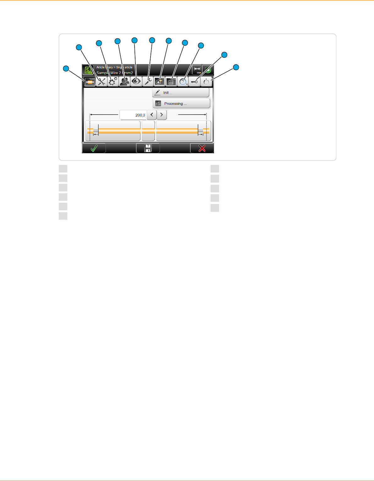
After touching the button “Navigation”, more global commands are shown.
1
2
3
4
10
11
9
5
6
7
8
1
Single article editor/article library
2
Setup
3
Conguration
4
User
5
Diagnostics
6
Services
7
Raw material library
1
8
Processing library
1
9
About ... (?)
10
Login
2
11
Shutdown
1
) - Is only displayed if under user - “User - interface", "Allow - library mode” is enabled.
2
) - Is only displayed if under user - “User - levels", "User levels - available” is enabled.
Navigation bar commands
Detailed information can be found in the appropriate main chapters.
Single article editor / article library
Display of the single article editor, where all the programming work to the article is done, or display of
the article library where article records are managed.
Setup
Easy set-up work on the machine and the tools. Here also the wizard for changing blades is located.
The set up is available in the user levels "Operator" and "Programmer".
Conguration
Detailed conguration of the control software S.ON. Setting of machine parameters. The congura-
tion is only available in the user level "Maintenance".
User
Setup of the user interface and the user level access rights.
Diagnostics
Detailed information system for the isolation of errors that can occur during production. The Diagnos-
tics is only available in the user level "Maintenance".
Service
Here data can be manipulated and library data be backed up, and the logging during the production
can be retrieved.

7. General handling / operation
Reference Manual | Edition 9.0 (03-2021) |
S.ON
35 | 214
Raw material library
Display and processing of the raw materials that are stored in the library. Is only displayed if under
user - “User - user interface", "Allow - library mode” is enabled.
Processing library
Display and processing of the Processing data that are stored in the library. Is only displayed if under
user - “User - user interface", "Allow - library mode” is enabled.
? (About ...)
This screen informs about the used software versions and the copy rights of third party software
installed additionally to S.ON.
Login
In the "Login screen", the individual user can log in directly to the desired user level. Is only displayed
if under “User - user - levels", "User levels - available” is enabled.
1 2
3
4
1
Login user level „Operator“
2
Login user level „Programmer“
3
Login user level „Maintenance“
4
Actual logged-in user level
The user is logging in to the appropriate user level with a password and can then access all com-
mands and parameter settings enabled for this level.
Procedure for entering a password: After touching the corresponding key for the user level, the
alpha numeric touch-keyboard is shown. In the text eld it is written for which user level the pass-
word is required. The password is displayed encrypted.
1.
▹
In the log-in screen select the desired [USER LEVEL].
2.
▹
[OK]

7. General handling / operation
36 | 214
Reference Manual | Edition 9.0 (03-2021) |
S.ON
➥ The alphanumeric touch-keyboard pops-up.
3.
▹
Enter the password via the keys.
4.
▹
Conrm the entry with [OK] or discard it with [CANCEL].
Shutdown
S.ON will be properly shut down and the MultiStrip 9480 automatically switched o. Before shutdown,
the warning message "Really shutdown?" is shown.
If the user was in the article editor when a shutdown is initiated, the shown/entered data are saved in
a memory buer. When a sub-screen of the article editor is opened, the data there get lost. If article
libraries are edited, the article library is used instead of the article editor. On restarting, the data are
loaded from the memory buer.
7.5.2
Production
In the header line of the touch screen the button "Production” is located. Touching this, shows the
production commands for the production control of the machine. If the user is in the conguration
settings, the key "Production" is hidden.
Some keys have a toggle state (e. g. loading or unloading a raw material). The selectable switching
state is shown bellow the key. Certain commands depend on others and only show-up if they are
selected rst.
If the MultiStrip 9480 is not ready for operation (e. g., if the communication between touch screen and
machine is not established) some or all keys are hidden. In such cases no production is possible. At
this point an appropriate message is shown.
Production commands (key pressed)
8
7
6
5
4
3
2
1
1
Unload/load
2
Open/close
3
Feed
4
Cut
5
Mode
6
Single
7
Run
8
Reset
Unload / load
After touching [UNLOAD] the feeding belts move backwards, the raw material is fed out
of the machine to the left and then the feeding belts open.

7. General handling / operation
Reference Manual | Edition 9.0 (03-2021) |
S.ON
37 | 214
A raw material is loaded automatically on the MultiStrip 9480. Feed the raw material by
hand up to the right feeding belts and then touch [LOAD]. The raw material is held by
the feeding belts, feed forwards, cut and the slug is ejected on the right of the machine.
NOTICE
Caution, property damage!
For MultiStrip 9480 with optional wire straightener, the raw material can be
squeezed or jammed on the inlet.
Always loosen the contact pressure on the wire straightener before executing
[UNLOAD].
Open / close
Opens the feeding belts to a pre-dened value set in the control software to remove the
raw material from the MultiStrip 9480. The cutting unit thereby moves out of the cutting
axis.
Closes the feeding belts and the blades to the pre-dened raw material diameter set in
the software. The cutting unit thereby moves into the cutting axis.
Feeding
The loaded raw material is fed forwards by the feeding belts as long as the key is press-
ed. Is normally used to feed the raw material beyond the cutting axis and to cut the
scrap wire piece with [CUT].
This command can only be executed if before [CLOSE] or [LOAD] was executed.
Cut
The loaded raw material is cut through and the slug is ejected. The slug is ejected from
the right feeding belts (in "short mode" it is not ejected).
This command is only activated if before [CLOSE] or [LOAD] was executed.
Mode
Production mode (normal operation): In normal mode a programmed raw material is
produced in one cycle if [RUN] was pressed. For trouble shooting or for analyzing a spe-
cial article and to optimize the settings, it can be of interest to execute the production in
step by steps and/or slow motion. The following additional modes are available:
Step by step: After [RUN] was touched, the production continues automatically but
much slower than in normal operation. Each step is initiated with a single touch of a key.
The step by step mode can also be automatically executed. For this each single process-
ing step is executed continuously with a selectable interval.
Speed control: After [RUN] was touched, the production continues automatically but
much slower than in normal mode. All movements are performed by default at speed
and acceleration set to zero. Each individual movement of the blades or feeding belts
may be carefully observed therewith. The speed can be increased during the produc-
tion.

7. General handling / operation
38 | 214
Reference Manual | Edition 9.0 (03-2021) |
S.ON
Step by step and speed control: Use step by step and speed control in combination.
The process is performed in steps and in slow motion. Speed and the interval can be
changed during the production.
Single
With single you produce a single piece of the currently programmed article. After the
production the article is ejected on the right of the machine and can then be checked to
give the user the opportunity to correct it before the regular production, if diering
measures or improper production quality results. The programmed wire quantity and
batch are not aected thereby. [SINGLE] can also be used to produce additional articles
after a completed production run.
This command is only activated if before [CLOSE] or [LOAD] was executed.
Run 1
The programmed quantity and batch are aected here as with [RUN]. To be able to pro-
duce with [RUN 1], "Single mode = Run 1" must be set in the "User interface".
Start
The normal production of a programmed article is started. The programmed quantity
and batch is produced in one cycle provided that no stop condition was programmed
before.
This command is only activated if before [CLOSE] or [LOAD] was executed.
Reset
The length counter for the already used-up raw material is reset.
Recoil brake
This key has the same function as the one on the machine front and is described more
detailed there. It shows up on the touch screen logically only if the raw material is not
loaded. If the option recoil brake is physically available, it must be activated in the "Con-
guration - Machine" before it can be used and before the key is displayed.
7.6
KEYS / COMMANDS / PICTOGRAMS
In the following chapter there is a description of the general operating elements and pictograms used
on the touch screen. These elements are partially combined with symbols and/or text for the better
overview.
For more information, see Chapter "17.1 Overview of symbols (Page 171)".
7.6.1
Toggle key / entry eld
Toggle keys are displayed depending on the function with or without symbol. They can have a dier-
ent shape relating to the switching state. There are also toggle keys with or without text.
These are keys for activating or deactivating a function or a procedure. Other elements and symbols
related to these functional elements, entry elds and graphics which are not assigned to a function in
the selected state are grayed out or disappear completely.

7. General handling / operation
Reference Manual | Edition 9.0 (03-2021) |
S.ON
39 | 214
1
2
3
4
1
Shift key activated
2
Entry eld activated
3
Entry eld deactivated
4
Shift key deactivated
7.6.2
Drop-down list
Here a selection of values (e. g. the length unit or the user interface language) can be set directly via
the keys in the opened drop-down list. In the selection key itself the actually set value or the option in
text form and/or the symbol is shown.
1
2
1
Set-up value
2
Drop-down list selection
7.6.3
Spin box / numeric touch keyboard
Value change directly in the entry eld
With the arrow keys, the displayed value left of the arrows can be decreased and increased. If the spin
box end value is reached, the arrow button is grayed out and the value can no longer be set.

7. General handling / operation
40 | 214
Reference Manual | Edition 9.0 (03-2021) |
S.ON
1
2
3
1
Spin box up/down
2
Set-up value
3
Spin box end value reached
Touching the entry area of the spin box opens the numeric touch-keyboard where the value is
entered directly via the numeric keys. See next chapter.
Value change via the numeric touch keyboard
If the entry area of a spin box or a digit is touched directly, a touch keyboard pops-up in which the
numeric value can be entered via the numeric keys or via the spin box keys.
1
2
7
4
6
5
3
1
Header with parameter name
2
Setting up/down
3
Pictogram of the function
4
Delete input to the left of the cursor
5
Minimum settable value
6
Maximum settable value
7
Currently set value
The entry is conrmed with [OK] or rejected with [CANCEL]. The entered values are checked in most
cases. If the value is out of the allowable range, the entry cannot be conrmed with [OK]. The cursor
jumps back to the data entry eld.
The data entry can also be carried out via a standard PC keyboard connected to the USB-connector.
7.6.4
Alphanumeric touch-keyboard
The alphanumeric touch-keyboard is used in article lists to name list entries (e. g. part name, Raw
material name, Processing name, name of an article library). They can also be used to enter or change
a password.
7. General handling / operation
Reference Manual | Edition 9.0 (03-2021) |
S.ON
41 | 214
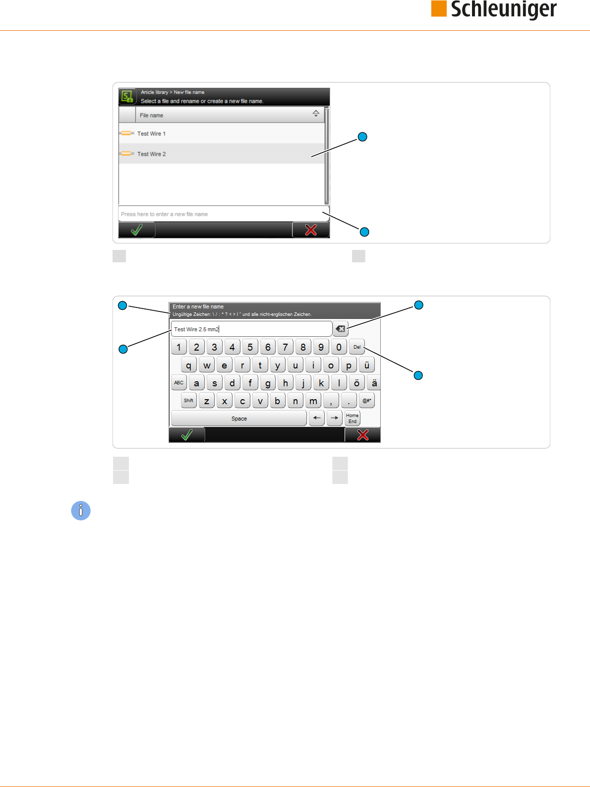
The touch-keyboard pops-up as soon as the corresponding text eld is touched.
1
2
1
Existing article list
2
New article entry eld
The entry is conrmed with [OK] or discarded with [CANCEL].
2
3
4
1
1
Display of entered data
3
Delete text right of the entry
2
Delete text left of the entry
4
Denition of data entry
The data entry can also be carried out via a PC-keyboard connected to the USB-connector.
7.6.5
Special entry elds and functions
Some elds (especially numeric elds) have a special function:
Password
The password is a combination of numbers and/or letters. Only stars are shown in the eld.
The following characters are not allowed during password entry: \\ / : * ? \ „ < > | and all not English
characters.
Protected
Protected entry elds cannot be activated and no data entry can be made. Entry elds are protected
e. g. if the user has no access right to it, or the change of the value is not provided in the actual pro-
gramming type. In this case, normally the eld disappears completely.

7. General handling / operation
42 | 214
Reference Manual | Edition 9.0 (03-2021) |
S.ON
Inch / mm
All values in elds containing length units, are in „Inch” or „Millimeters”. The length unit to be used has
to be set in the "Conguration".
7.6.6
Dialog window
During programming or the production, the data entry is checked against their validity. For example,
after a parameter change often a message is displayed, what action the user intends to change.
Information
An information is shown if S.ON a communication issues or a decision is necessary.
Warning
A warning is shown if a requested action from the user is risky (e. g. data loss).
Error
An error is shown if a requested action from the user is not valid e. g. deleting a saved write protected
article or if errors occur during the production. For further information to error protocols, see the
chapter "15.1.3 Logging (Page 163)".
Wait dialog
There are also wait dialogs. They only contain a message, no interaction is necessary. They are used if
e. g. the calculation of a set value lasts some time, or when mechanical components are to be calibra-
ted.
7.6.7
Lists and libraries
Here data in tabular form are shown (e. g. the programmed, saved articles from the article library or
Raw Material data). In the next gure an example of an article library is displayed.

7. General handling / operation
Reference Manual | Edition 9.0 (03-2021) |
S.ON
43 | 214
3
4
6
5
1
2
1
List lter
2
List view
3
List header
4
List contents area
5
Scroll-bar
6
Global list commands
List lter
Files can be ltered according to specic criteria (e. g. to search for strings). Here a lter text can be
entered in order to nd the desired les.
List view
Changes the display of the le entries. We can select between "File view only" and "File view with
Date".
List header line
Naming the list column. By touching a column header, the list entries are sorted ascending or
descending. The sorting direction is marked with an arrow symbol on the right of the header.
List contents area
Shows data of the article library, Raw material-, Processing library and others. After touching a list
entry twice, the corresponding editor is opened.
Scroll bar
By touching the touch screen and moving the nger up or down, we can scroll in the list, see chapter
"7.7 Data management (Page 43)".
Global list commands
Depending on the list type, we nd additional common commands to the actual list (e. g. creating a
new list entry, global selection/deselection of all list entries). Specic list commands are described in
the respective chapters in detail.
7.7
DATA MANAGEMENT
In the lists, article libraries, article lists, Raw material- and Processing libraries are loaded, created from
scratch, saved, renamed and managed in other ways. Here common commands are explained, which
are valid for all le screens. In all the lists we nd common procedures for the le storage after pro-
gramming and for the handling of the saved les. Specic le commands however are explained in
the respective chapters to the processing modes in detail.
7. General handling / operation
44 | 214
Reference Manual | Edition 9.0 (03-2021) |
S.ON
For the work with S.ON, there are lists for the individual processing modes and the conguration avail-
able:
Single article
Article library
Article list
Raw material- and Processing libraries
Blade cartridge library
Before switching o the MultiStrip 9480, after work, S.ON remembers from which screen the machine
was switched o, e. g. if from the article editor ("Standard process ow", "Library mode", "Article list
mode") or from the article library. According to this, this screen is shown rst after a restart. If the user
level control was activated before, the log-in screen shows up rst.
7.7.1
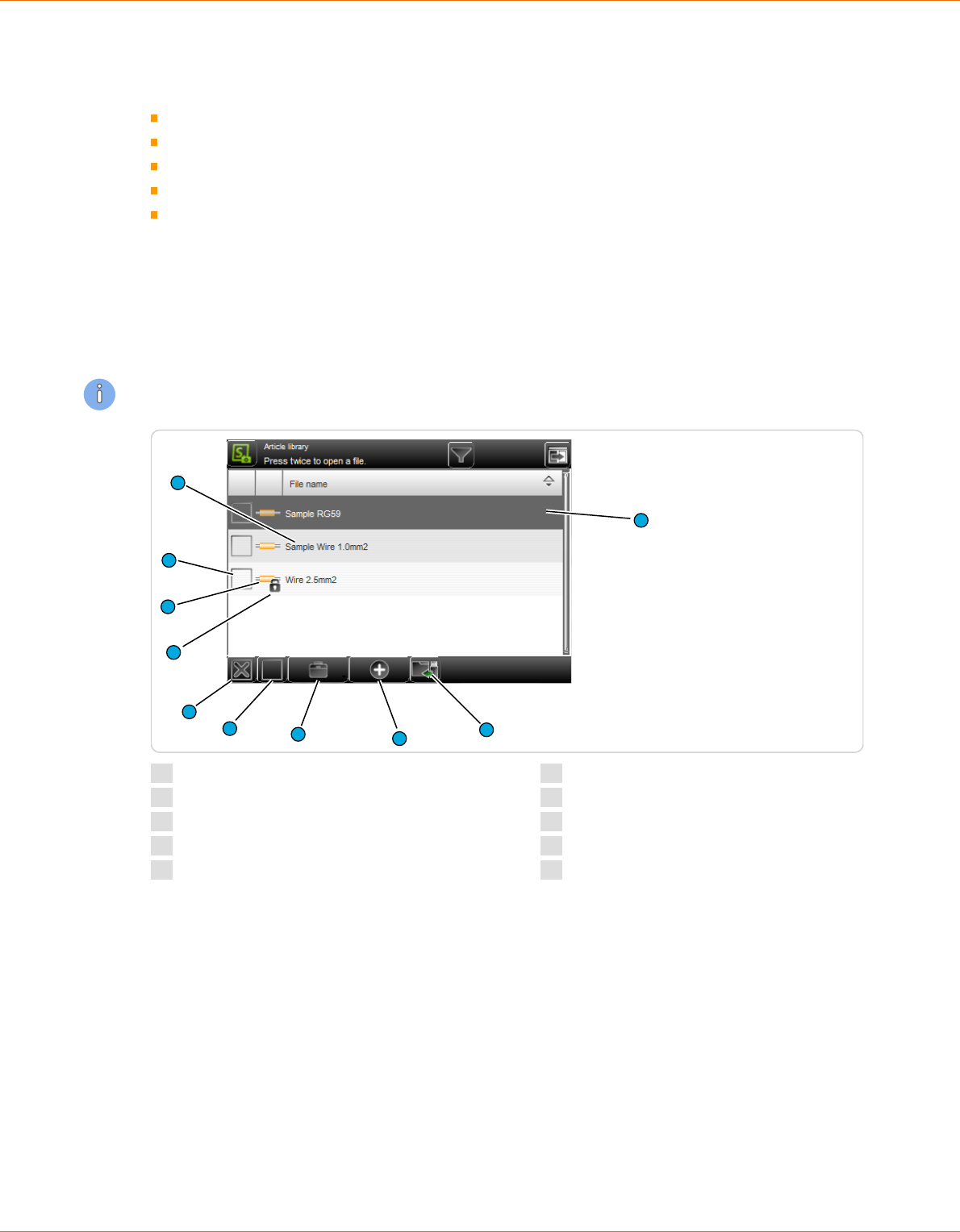
Overview
The display and function elements of the library in the article list mode diers in some details from all
other le lists. See Chapter "10 Article list mode (Page 111)".
1
6
7
4
3
5
10
8
9
2
1
File description
2
File highlighted
3
Import le
4
Create new le
5
File options
6
Deselect all les
7
Select all les
8
Write protection activated
9
File type
10
File selected
7.7.2
Description
File name
Unique identier of the le entry in text form (e. g. article number of the wire/cable). The entries are
sorted alphabetically by default, but can be sorted individually by touching the column header in the
respective column in ascending or descending order (arrow).
File highlighted
A le is for le manipulation (duplicate, rename), or to open in the article editor (touched again) high-
lighted.
7. General handling / operation
Reference Manual | Edition 9.0 (03-2021) |
S.ON
45 | 214
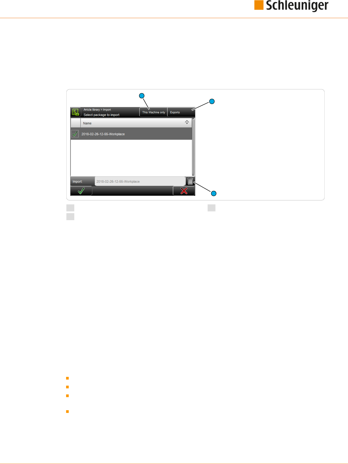
Import le
Here previously exported data can be read-back (imported) from an USB memory stick connected to
the rear of the machine.
In the article library also, either the selected articles only can be imported, or the import le can
include the corresponding Raw material- and Processing data as well. If the le to be imported
already exists, a warning message shows up.
1
1
2
3
1
File lter
2
Exports
3
Delete le
File lter
It can be dened, if only the data shall be displayed from this machine in the list or also data from
other machines and from the wire processing software CAYMAN.
Exports
Shows only export packages or also backup packages.
Delete le
The highlighted data in the list, saved on the USB memory stick, are deleted.
Create new le
This creates a new le (e. g. a new article or a new Raw material). For easy nding the data, a meaning-
ful name (e. g. the part number of the wire) shall be entered here.
Then the article editor is opened and the article can be programmed. More information for creating a
new article are explained in the respective chapters to the processing modes.
File options
Here, more le manipulation commands are available.
Duplicate highlighted le: For an existing saved le, a copy with the same settings is created.
Rename highlighted le: Changes the le name of the selected le.
Delete selected les: All selected (selected with a cross) les will be deleted. The les are deleted
irrevocably. Before this action, the user is asked "If he really wants to delete the les?".
Loch/unlock selected les: The write protection can be activated for each le individually. Inad-
vertently deleting or changing a list entry is not possible anymore. On any attempt, a warning
message shows up!

7. General handling / operation
46 | 214
Reference Manual | Edition 9.0 (03-2021) |
S.ON
Export selected les: The selected list entries are saved to an USB memory stick. For this, an USB
memory stick must be connected to the machine rear. If desired the export can include the Raw
material- and Processing data as well.
Convert selected les: Old selected les, created with a previous software version are converted
to the actual one (this saves a conversion in the background).
Select / deselect all les
All les in the le list are selected or deselected for further manipulation.
Write protection enabled
Indicates that the le is marked via "File options" as write protected. No changes can be made to this
le. The write protection can be removed via "File options" (the user hence must be logged in to the
corresponding user level).
File type
Shows in which operating mode the le was saved (e. g. single article or article list).
File selected
At selected les the user can through the "File Options" execute additional commands (delete, lock,
unlock, export, convert).
Open le
By touching the according list entry twice, the contents of the le is loaded into the corresponding
editor.
7.7.3
File name convention
While typing in the le name remember to only enter characters in the ASCII range of 1 to 127. (Inva-
lid characters are: \\ / : * ? \ „ < > | and all non-English ones).
7.8
SAVING ARTICLE
After programming an article in the article editor, the article normally is saved permanently in the arti-
cle library. If the machine was shut down without saving, the data of the actual programmed article is
saved only in the memory buer and is shown rst after restarting. If also data in lower levels have
been changed (e. g. Processing) however they are lost.

7. General handling / operation
Reference Manual | Edition 9.0 (03-2021) |
S.ON
47 | 214
The relevant storage commands are available in the footer area of the respective editor:
1
2
3
1
Save
2
Save as...
3
Discard changes
7.8.1
Save
[OK] : All changes are written back to the library under the name dened when the article was cre-
ated. First the user is asked; „If he wants to overwrite the existing data?“ -> Conrm with [OK] or dis-
card with [CANCEL].
7.8.2
Save as...
[SAVE AS...]: After changing an already available article from the library, the changed data can be
saved directly under a new name to the library. The entry dialog for the new article name is shown.
Enter new name and conrm with [OK]. After this, the article editor is shown again.
7.8.3
Cancel changes
Discard changes made in the article editor with [CANCEL] and go back to the article library. The previ-
ously made settings are not saved. For safety reasons, a warning message is shown „Data have been
changed, really want to cancel?“.
7.9
SHOW ARTICLE
In the header area of the article editor, the actually loaded article is shown.
1
1
Display le name

7. General handling / operation
48 | 214
Reference Manual | Edition 9.0 (03-2021) |
S.ON
7.10
SETUP OF VIEWS AND MODES
The work on the touch screen can be carried out in dierent views and modes. This helps the opera-
tor or also the beginner to get familiar quickly with the production and programming platform. The
selection can be made via the "Navigation"- and "Mode" keys.
The following important selections are provided:
Key command Mode/view User group
Measuring mode (given value) Operator, programmer
Correction mode (correction value) Operator, programmer
"Setup” view Operator, programmer
“Conguration" view Maintenance
7.10.1
Toggle measuring mode / correction mode
Due to the way an article is produced or also due to the nature of individual articles, length and/or
position irregularity can occur during the production. For this reason the correction mode was imple-
mented. Here corrections of the wire length, the pull-o length and the position of the areas can be
entered.
If the correction mode is activated it is possible to enter a positive or negative correction value in the
length entry elds and also in the application screens in the position entry elds. After the correction
entry the user can switch back to the measuring mode. The correction value is now displayed colored
in the entry eld. This additional measure is taken into consideration during the production of the
article.
Measuring mode (given value):

7. General handling / operation
Reference Manual | Edition 9.0 (03-2021) |
S.ON
49 | 214
Correction value (Correction value):
Example: Correction of wire length
The wire length is increased by 1.5 mm in the example below.
If the correction mode is on, the user opens directly the numeric touch-keyboard by touching [ENTER
CORRECTION VALUE] where the eective measured length can be entered.
After touching [OK], the correction value is automatically calculated.
7.11
ENHANCED FUNCTIONS
7.11.1
“SmartDetect”
Functional principle
The “SmartDetect” monitoring system is used to monitor the stripping process. It detects slightest
touches of the blades with the conductor during the processing. If a conductor contact is detected,
normally a message is generated and the stripping process is stopped.
The "SmartDetect" measurement always aects just a single pull-o operation, where two sepa-
rate measurements are made.
● Incising: During the incision it will be examined, for which diameter for the rst time conduc-
tor contact occurred. (for the measurement, the blade geometry must be taken into account.
For V-blades, the point of contact on the conductor does not correspond to the reference
position of the blades, but to the edges of the blade.
● Pull-o: It will be checked how much conductor contact during the entire pull-o operation
took place.
The user can dene limit values for each pull-o action, to which point a pull-o has to be at a
proper quality.
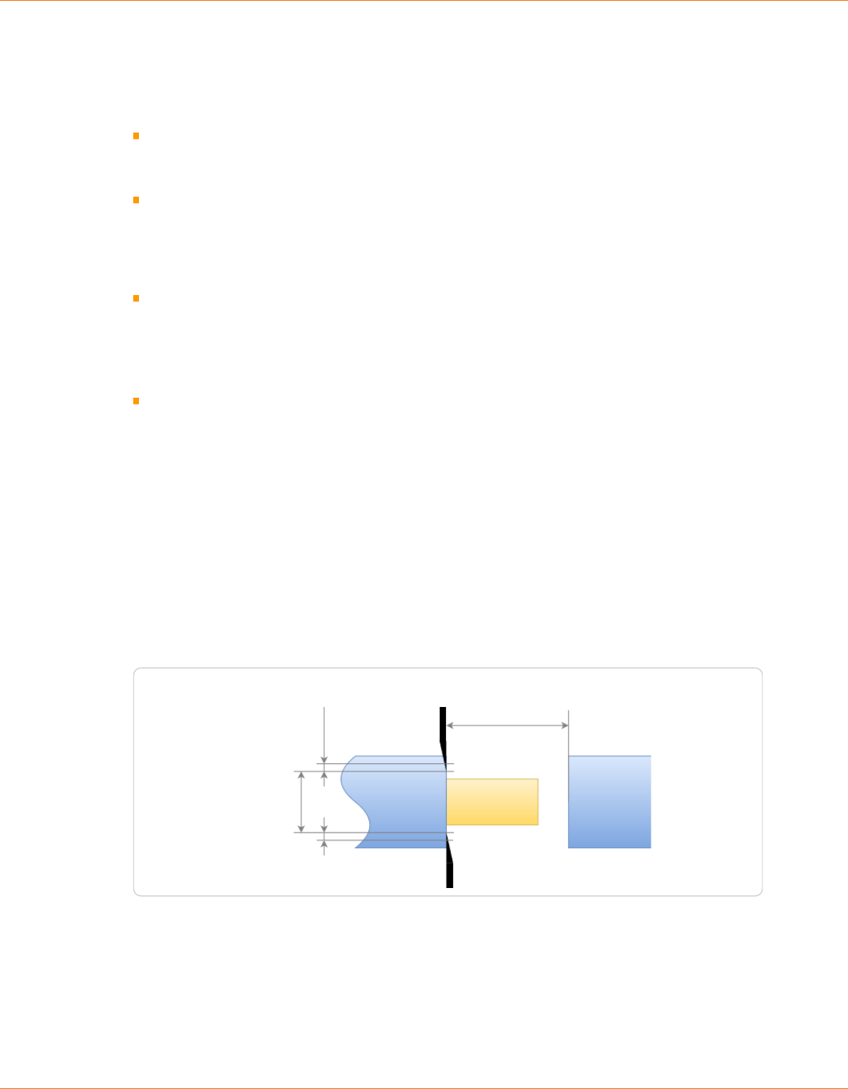
7. General handling / operation
50 | 214
Reference Manual | Edition 9.0 (03-2021) |
S.ON
● Incising: Maximum permissible tolerance of the incising diameter to the diameter of the rst
detected contact.
● Pull-o: During what percentage of the total pull- o action may the blades touch the con-
ductor.
Evaluation in the event of an error
● In the event of an error variances are described in detail with actual and setpoint values.
● The production is stopped directly after the defective operation.
Displaying messages
● Continue production and ignore the “SmartDetect” message if the conguration setting
allows this. Otherwise, abort the production, the workpiece stays where it is and the bad part
must be disposed of manually.
● For detailed information to the messages, see chapter "7.11.3.1 Ignore function (Page 52)".
Tests prior to the start of a production cycle
● If "SmartDetect" is enabled in a Processing element, it must be enabled in the conguration.
● If "SmartDetect" is enabled in a Processing element, the selected blade must support
“SmartDetect”.
● Deviations are issued via an error message and the production can not be started.
General monitoring of the "SmartDetect" system
● At the beginning of the production a referencing (Sweep and Adjust) is executed. The blades
must be closed for the Sweep and open for the Adjust. If something fails thereby, the produc-
tion must not start.
● In addition, a referencing Adjust is carried out at the following times: When reaching the end
of production, batch, quantity, article list, total quantity and production stop. Thereby the
blades must be completely open. If this fails, the production is stopped and the user is
warned that perhaps the last pieces produced were not monitored with "Smart Detect".
● No contact must be detected immediately before incision or cutting through. If it does, the
production will be stopped.
● If the cutting through of a wire is carried out with a "SmartDetect" blade, compulsory contact
with the conductor must be detected. If not, the production is stopped. This does not apply to
the cutting through or cutting of a waste piece.
● All the tests are executed only if at least one pull-o operation is monitored.
Pull-off length
Offset in Ø
For allowed touch
Incising diameter
Limits of "SmartDetect"
Temporary mechanical deformation (spring/rubber eect) of the cutting unit can not be compensa-
ted by the control software. Depending on the size and mechanical resistance of the wire the meas-
urement can dier from the real conductor contact.

7. General handling / operation
Reference Manual | Edition 9.0 (03-2021) |
S.ON
51 | 214
Tips for an error-free production
To ensure that the production runs without interruption and, if possible, no touches occur, the follow-
ing recommendations are to follow:
Apply a partial strip instead of a full strip. The shorter the pull-o way, the lower the probability of
contact. In the event of a full strip, strands tend to spread.
Switch on the function “Regrip”. The blades grasp on the insulation for stripping. This prevents the
blades from damaging the conductor.
Enlarge the conductor diameter so that the blades incise less far into the insulation.
Enlarge the way back so that the blades have more distance to the conductor during stripping.
Settings
See chapter "8.5.3 Elements (Page 67)" and "12.4.5 Monitoring (Page 137)".
Further information
“SmartDetect" is an option and requires a special cutting unit. See chapter "12.4.3.2 Congure/activate
blades (Page 135)".
7.11.2
Sensitivity correction
The sensitivity is set directly in the hardware. With this set sensitivity, the sensor either detects a con-
tact or not.
Relevant for the calculation are:
Raw material length
Programmed incise diameter of the current article.
The correctly programmed diameter is important: Corrections in the blade lengths must really be
made on the blade, otherwise a wrong sensitivity will be calculated.
The same sensitivity is set at the left and right ends.
For urgent needs in the Processing element of
the article, a correction of the calculated sensi-
tivity values can be made. The value range is
between -5 (most insensitive) and +5 (most sen-
sitive).
A correction should only be performed in an
urgently necessary case.
If a contact is not detected during an inci-
sion, the value can be increased. However,
this also increases the risk of false triggers.
If false triggers occur, the value can be
reduced. But perhaps real contacts are then
no longer recognized.
7.11.3
Disposal of rejected pieces
Depending on the situation, defective pieces detected by SmartDetect are disposed of before the
blade or after the blade in the machine. The various setting options are described below. A successful
production with SmartDetect also depends on the quality of the raw material.

7. General handling / operation
52 | 214
Reference Manual | Edition 9.0 (03-2021) |
S.ON
Ignore function
Procedure with SmartDetect without Ignore
function:
Prerequisite: In the “Monitoring” conguration,
SmartDetect is turned on and the “Ignore” error
message key is turned o.
If a SmartDetect contact occurs during production, warning 5955 appears with a detailed description
of the contact and recommendations for further action to resolve the problem.
F1: Accept contacts and continue. Accepting that the system has detected a contact. The current
piece is rejected (according to the existing setting) and not counted in the produced quantity.
F7: Cancel production. The current production is canceled. The rejected piece must be rejected
manually.
The display frequency of the message depends on whether the mode “Single” or
mode “Start (Start 1)” is in use.
The display duration of the message is set in Conguration - Quality assurance. See chapter "12.4.9
Quality Assurance (Page 140)".
Procedure with SmartDetect with Ignore func-
tion:
Prerequisite: In the “Monitoring” conguration,
SmartDetect is turned on and the “Ignore” error
message key is turned on.
Also with this setting the warning 5955 appears with a detailed description of the contact and recom-
mendations for further action to resolve the problem. In addition to F1 (Accept contacts and contin-
ue) and F7 (Cancel production), F2 (Ignore contacts and continue) is available:
F2: Ignore contacts and continue. Ignoring that the system has detected a contact. The article
production is continued. If there is no further contact, the article is counted as “produced” in the
quantity produced.
If there is another contact, the same procedure starts with a new warning 5955. React with F1 or
F2 or F7. This can be done on the same article as often as necessary.

7. General handling / operation
Reference Manual | Edition 9.0 (03-2021) |
S.ON
53 | 214
Setting the output signal
If required, a signal can be sent to a subsequent
device (e. g. a robot) via Signal I/O assignment.
Prerequisite: In the Quality assurance congura-
tion under “Rejected pieces”, "Signalize" is
switched on.
However, this only means that a signal can be
set. The actual signal setting is done in "Cong-
uration - Machine - Interfaces - Library Signal I/O
Assignment".
See chapter "12.4.2.6.1 Signal I/O (Page 130)".
Limitation of number of errors
In the "Quality assurance" conguration, "Auto-
matic conrm" must be activated so that the fol-
lowing two types of counter types can be set.
Allowed sequential Number of allowed suc-
cessive contacts of the blade with the con-
ductor during production.
Allowed cumulated: Total number of
allowed contacts of the blade with the con-
ductor during production.
As soon as one of the two counters is reached and the defective piece has been rejected, the machine
stops and error message 5955 appears with the following informations:
Which counter was reached, the counter reading and the congured maximum value.
Which counter was not reached, the counter reading and the congured maximum value.
History of the last rejected articles with reasons for the sorting out.
This last error message is not automatically accepted but must be acknowledged.
Discarding a rejected piece
The length and type of the piece play a role in deciding what to do with the rejected piece.
If the right element has had a contact, the defective piece is cut o and a new attempt is made auto-
matically. Depending on the conguration, a dened number of attempts is possible until the
machine stops.
No oset device involved, error on the right element: The defective piece is cut o as short as pos-
sible to save material. After the blade, the rejected piece falls into the receptacle in the machine.
With oset device involved, error on right element or error on left element: The complete piece is
nished and then disposed of according to conguration in front of the blade.
See also chapter "8.5.6.2 Dispose waste piece (Page 74)".
Rejected piece with text variables
S.ON supports seven dierent predened text variables, see chapter "8.7.2 Dened text (Page 85)".
Most text variables can be treated as normal text for the rejected pieces. Exceptions are the text varia-
bles Quantity produced @3, Batch produced @4 and Counter @5: If a piece that is printed with one or
more of these variables is rejected, a waste piece is produced and the post-production occurs auto-
matically.

7. General handling / operation
54 | 214
Reference Manual | Edition 9.0 (03-2021) |
S.ON
@1 Time
✓
No waste piece
@2 Date
✓
No waste piece
@3 Quantity pro-
duced
✕
Slug
@4 Batch produced
✕
✓
depending on the situation (batch size and number of pieces remain-
ing within the batch)
@5 Counter
✕
Slug
@6 Toggle bold
✓
No waste piece
@7 File name
✓
No waste piece
Variable Quantity produced @3: If Quantity produced is used, the pre-printed texts are general-
ly rejected when a piece is rejected.
● Next step: Production is automatically continued with the number that was rejected.
Variable Batch produced @4: If the Batch number is used, depending on the batch size and the
situation, articles with pre-printed text will be rejected as waste when a piece is rejected.
● Next step: Production is automatically continued with the number that was rejected.
Variable Counter @5: If the Counter is used (the variable Counter @5 is unique as opposed to the
variable @3), the pre-printed texts are generally rejected when a piece is rejected. A waste piece is
always produced after the rejected piece.
● Next step: Production is automatically continued at the next higher counter number, as the
counter number can only occur once.
Restrictions
Partial stripping pushes the insulation beyond the wire end, but it is not known how far. There-
fore, when discarding a rejected piece, it is assumed that it protrudes no more than 50 mm. If
more insulation protrudes, the raw material collides with the guides or it can no longer be grip-
ped correctly with the belts.
For production with oset device: If the last article to be produced in an article list results in a
rejected piece, a waste piece is always produced, despite the setting “Production - prepare” and
although this wire was correctly pre-produced.
7.11.4
Manual declaration of rejected pieces
After nished or interrupted production the quality of the produced pieces can be checked manually.
This is possible in the production control of the article.
If the piece is classied as non-acceptable, it can be manually declared as a rejected piece.

7. General handling / operation
Reference Manual | Edition 9.0 (03-2021) |
S.ON
55 | 214
Example: Declare rejects
1.
▹
The planned number of pieces to be pro-
duced can be seen in the “Quantity” eld
1
.
After production, the number of pieces pro-
duced can be seen in the “Produced” eld
2
.
2.
▹
Enter the number of manually rejected
pieces in the “Declare rejects” eld
3
.
3.
▹
[CONFIRM].
4.
▹
The number of rejected pieces is now listed
in the “Rejected“ eld
4
and therefore the
number of pieces for the post-production is
listed in the “Remaining” eld
5
. The num-
ber of pieces produced in the "Produced”
eld
2
has been reduced by 2 accordingly.
5.
▹
[RUN]
6.
▹
Result of the post-production
➥ The “Remaining” eld
5
now shows the
number of 0. The number of pieces pro-
duced
2
corresponds to the planned
number
1
. The number of rejected pieces
4
is displayed unchanged.
Rejected pieces (including those detected by SmartDetect) can be declared good after manual
verication, i. e. the rejected piece can be manually ignored. This option is only oered if the
“Ignore” setting is activated in the “Monitoring” menu in the conguration.
1
2
3
4
52
4
5
1
2

7. General handling / operation
56 | 214
Reference Manual | Edition 9.0 (03-2021) |
S.ON
Example: Ignore rejects
1.
▹
Rejected pieces
4
can be manually ignored,
i. e. be declared good.
2.
▹
In the „Ignore rejected“ eld
5
enter the
number of rejected pieces to be ignored.
[CONFIRM].
3.
▹
A total of 8 pieces were produced, 2 more
than planned. This causes the machine to
automatically start another production
cycle. Therefore, the “Produced” eld
2
shows the dierence between the actual
number of pieces produced (8 in total) and
the planned number
1
(here 6), i.e. 2. In the
“Remaining” eld
5
the dierence between
the planned number (here 6) and the num-
ber in the “Produced” eld (here 2) appears,
i.e. 4. This limitation is known.
4.
▹
This is somewhat more obvious when pro-
ducing an article list: The production cycle
6
is automatically increased by 1 when the
above situation occurs.
4
5
2
1
5
6

7. General handling / operation
Reference Manual | Edition 9.0 (03-2021) |
S.ON
57 | 214
7.11.5
CAYMAN-Support
If the MultiStrip 9480 is controlled via the wire processing software CAYMAN, an additional screen
selection is displayed in the navigation bar, where the communication can be established. For this,
the MultiStrip 9480 must be connected via an ETHERNET interface cable to the PC.
To activate CAYMAN proceed as follows:
1.
▹
NAVIGATION
2.
▹
[CONFIGURATION]
3.
▹
[MACHINE]
4.
▹
[OPERATING UNIT]
5.
▹
Under CAYMAN, activate “Support”.
For more information and settings on the wire processing software, refer to the "Reference manual -
CAYMAN".
As soon as the MultiStrip 9480 is connected with CAYMAN the following connection screen is dis-
played on the touch screen:
The installation and the operation of CAYMAN is described in the „Operator Manual“ of this product in
detail.
7.11.6
Load le with barcode scanner
Generally the entry via the bar code scanner functions in S.ON the same way as for the touch key-
board. The value will be scanned during the scan command directly into the input eld and can be
conrmed with [OK] .
If the user is in the article library or in the single article editor, in case of a scan command, the barcode
is read in and the article is directly opened in the single article editor. The prerequisite for this is that
at least four characters of the article name already exist in the article library. If an existing article in the
single article editor is in progress, which has not yet been saved, a warning message is displayed.
The barcode may also contain only the beginning of the article name. If a search is unique to the
name beginning the article will be opened. If with the barcode no or several items are found, an error
message appears.
Restriction: The le names must not contain spaces, since otherwise the barcode automation is not
working properly.

7. General handling / operation
58 | 214
Reference Manual | Edition 9.0 (03-2021) |
S.ON
For hardware requirements and connection of the barcode scanner, see the "Reference manual of the
machine".

8. Standard process ow
Reference Manual | Edition 9.0 (03-2021) |
S.ON
59 | 214
STANDARD PROCESS FLOW
The S.ON control software can, as described already, program articles dierently. Here all the impor-
tant basic settings for the programming are described, which apply to the “Standard process ow”.
The description for the other modes contains only supplementary explanations.
In the single article editor most of the settings are treated. This screen is the so called central operat-
ing platform, where the user gains access to all settings available in this user level like Raw material
type, length and stripping parameters.
8.1
PRINCIPAL “STANDARD PROCESS FLOW”
Application editor
Processing editor
Start of machine
Application editor area
Init
Raw material type
Article library
Single article editor
Application
Fig. 6: Principal, “Standard process ow”

8. Standard process ow
60 | 214
Reference Manual | Edition 9.0 (03-2021) |
S.ON
8.2
SINGLE ARTICLE EDITOR OVERVIEW
Tab 1 (article editor)
3
68
4
9
5
2
7
1
1
Init
2
Processing
3
Wire length
4
End application right
5
Swap area
6
Area application
7
Name le
8
Activate area
9
End application left
Tab 2 (production control)
2
3
4
1
7
8
9
10
11
12
5
6
1
Rejected pieces
2
Declare rejects
3
Conrm entry
4
Ignore rejects
5
Conrm entry of ignored rejected pieces
6
Total counter reset
7
Batch remaining
8
Batch size
9
Activate batch processing
10
Remaining pieces

8. Standard process ow
Reference Manual | Edition 9.0 (03-2021) |
S.ON
61 | 214
11
Produced pieces
12
Quantity pieces
Tab 3 (messages)
1
2
3
4
5
6
1
Enable comments
2
Remarks text entry
3
Before production text entry
4
After production text entry
5
After production activate
6
Before production activate
8.3
SINGLE ARTICLE EDITOR DESCRIPTION
For the measuring units of the following settings, the settings in the "Conguration" are valid.
8.3.1
Init
See chapter "8.9 Init (Page 89)".
8.3.2
Processing
See chapter "8.5 Processing editor (Page 65)".
8.3.3
Wire length
Denes the length, the raw material is to be cut to. The length entry is limited by the length of the
application type, thus the applications cannot be rendered useless through an insuciently long
length entry.

8. Standard process ow
62 | 214
Reference Manual | Edition 9.0 (03-2021) |
S.ON
8.3.4
End application left / right
No stripping
The Raw material is not stripped, no stripping oper-
ation is performed. It is solely cut to the program-
med length and then ejected.
Full strip
This stripping type is suitable for removing the
jacket of standard wires or for stripping the insula-
tion from 2-layer wires.
If the pull-o length is greater than the stripping
length, a full strip is performed.
Example full strip: Stripping length = 20.0 mm, pull-o length = 25.0 mm
Partial strip
This stripping type is suitable for removing the
jacket of standard wires or for stripping the insula-
tion from 2-layer wires.
Example partial strip: Stripping length = 20.0 mm,
pull-o length = 10.0 mm
Window strip
This processing type is suitable for individual strip-
ping and stripping with windows.
Example: Stripping length = 20.0 mm, pull-o
length = 10.0 mm, window position = 30.0 mm,
window length = 5.0 mm
Multi layer
This application type is well suited for coaxial
cables, especially when partial strips have to be
programmed.
Inserts an (usually) immediately producible full
strip for all processable layers. (the strip sequence has been optimized for the standard coaxial
cables).
Example: Jacket stripping length = 40.0 mm, jacket pull-o length = 45.0 mm, shield stripping
length = 30.0 mm, shield pull-o length = 35 mm, dielectric stripping length = 20 mm, dielectric pull-o
length = 15 mm
Multi conductor
Suitable for wires with more than one conductor
e. g. power cords. First the jacket is stripped com-
pletely, then the wires are placed side by side using
the optional combing unit and nally they are
stripped with a multiple radius blade.
Example: Stripping length = 8.0 mm, pull-o length = 6.0 mm, jacket-stripping length = 40.0 mm

8. Standard process ow
Reference Manual | Edition 9.0 (03-2021) |
S.ON
63 | 214
Flat ribbon
The Flat ribbon (also called Zip cord) require a spe-
cial treatment using several dierent operation
modes. First, they are separated, and then stripped,
then one conductor is shortened and nally this
shortened conductor is stripped.
The application at ribbon is intended especially for this complex treatment and with other types,
simply makes full strips on each layer. Special blades are required for separating and stripping.
Example: Separate (length) = 40 mm, stripping length 1 = 10.0 mm, pull-o length 1 = 5.0 mm, short-
en = 15 mm, stripping length 2 = 25 mm, pull-o length 2 = 5 mm
See also Chapter "8.6 Application editor (Page 79)".
8.3.5
Area application
See Chapter "8.7 Application editor area (Page 82)".
8.3.6
Swapping areas
Exchanges the left area with all its area application settings with the right one and vice versa, the
areas are mirrored therewith horizontally and vertically.
A message shows up, if the mirrored text is not congruent with the original one.
8.3.7
Activate area
Activates or deactivates the specied area function. If this function is o, all settings of the area appli-
cations are ignored during the production.
8.3.8
Rejected pieces
Displays the number of rejected pieces that have been entered and conrmed in the eld „Declare
rejects“.
8.3.9
Declare rejects
After manual inspection of the produced pieces, enter the number that must be rejected. Depending
on the machine, rejecting can be done automatically using the optional "SmartDetect" function.
8.3.10
Ignore rejects
After manual inspection of the rejected pieces, indicate the number that is considered good, i. e. to be
ignored.
8.3.11
Reset production counter
Resets all production counters back to its initial state. This function is used when a new production
run is to be started. Produced, remaining and batch remaining are reset.
8.3.12
Remaining batch size
Shows the quantity of article batches still to be produced since the last production start. The value
can be reset to zero with the command [RESET PRODUCTION COUNTER].

8. Standard process ow
64 | 214
Reference Manual | Edition 9.0 (03-2021) |
S.ON
8.3.13
Batch size
Entry of the total quantity of batches to be produced.
8.3.14
Activate batch
To break down the quantity dened under "Quantity", a batch value can be entered which subdivides
the production of the article into smaller quantities (batches). Depending on the settings in "Article
list - Production settings", the production is stopped after each produced batch and a message shows
up on the touch screen.
If this function is selected, an additional entry eld is shown, where the batch size is entered.
Batches can be used with post processing devices (e. g. WireStacker) to initiate certain actions. The
"Quantity" is either divided in partial orders or it is performing continuously (batch deactivated).
8.3.15
Remaining articles
Shows the amount of articles still to be produced since the last production start. The value can be set
back to the "Total" with the command [RESET PRODUCTION COUNTER].
8.3.16
Produced articles
Shows the quantity of already produced articles since the last production start. The value can be reset
to zero with the command [RESET PRODUCTION COUNTER].
8.3.17
Quantity
Entry of the quantity of articles to be produced.
8.3.18
Remarks / messages
Remark elds for comments in conjunction with the to be produced article. Here also messages
before or after the production can be entered here, e. g. before the production to advise the operator
to change the sealing foil on the HotStamp, before the production continues.
8.4
SINGLE ARTICLE EDITOR FURTHER SCREENS
Raw material data as well as Processing’s and settings to the production process are treated based
from the single article editor in dierent screens (editors).
6
5
4
3
2
1
1
Init "Page 89"
2
Processing editor "Page 65"
3
Editor application right "Page 79"
4
Editor Editor application area "Page 82"

8. Standard process ow
Reference Manual | Edition 9.0 (03-2021) |
S.ON
65 | 214
5
Editor application left "Page 79"
6
Raw material editor
1
"Page 87"
1
) - Only Raw material types: Diameter, multi-layer, multi-conductor, at ribbon
A distinction is made between two dierent application types:
End application: Denes how the left and/or right ends (application) shall be processed (stripped).
Area application: Settings for the positioning and shape of the marking stamped on the produced
article.
8.5
PROCESSING EDITOR
8.5.1
General overview
The way how S.ON processes a certain type of article is dened in the Processing. This records
describe how the MultiStrip 9480 processes a Raw material type (e. g. a Multi conductor or a Flat rib-
bon). This is determined by data such as speed, incising depth, way back, air jet time, utilized blades
etc. All settings for the Processing are entered in the Processing editor.
1
2
3
Fig. 7: Processing editor overview
1
Tab selection
2
Content area
3
Default
The following is an overview of the individual tabs and their function:
Tab Concerns the Description
Elements Stripping unit Instructions for the execution of operations (strip,
comb, slit, separate, shorten).
Feed Feeding unit Settings concerning the raw material feeding by the
feeding belts/rollers.
Cut Stripping unit Instructions for the cutting unit movement during
cutting the raw material.
Options Miscellaneous Denitions made for the feed monitoring and the
behavior when executing a full strip on the right end
and the connected post processing devices.
Rotary incising
unit
Cutting axis Settings for the rotary incising unit (rotary speed,
blade position, centering).

8. Standard process ow
66 | 214
Reference Manual | Edition 9.0 (03-2021) |
S.ON
Tab Concerns the Description
Comment Production General comments in the Processing to the produced
articles.
8.5.2
Default
First the raw material must be dened for the article to be processed. Afterwards, S.ON can automati-
cally calculate the necessary processing values for correct execution.
This automatic setting is adequate for an error free production with most standard applications. If e. g.
the outer jacket diameter diers from the default value, the Processing values must be altered in the
“Processing editor” accordingly.
Default tab “Elements”
After pressing “Default” in the tab “Elements” a
selection is oered for the use of the default set-
ting:
Apply to selected element
Apply to current tab
Apply to all tabs
Default other tabs
In the remaining tabs, "Apply to current tab" and "Apply to all tabs" are available.

8. Standard process ow
Reference Manual | Edition 9.0 (03-2021) |
S.ON
67 | 214
8.5.3
Elements
Denes all settings of the Processing elements. This can be incision diameter, possible operating
modes etc.
1
6
5
4
3
2
Fig. 8: Processing elements
1
Application type
2
Show next column
3
Header element column
4
Parameter values
5
Default
6
Parameter name
Application type
Schematically representation of the loaded application with display, which Processing element
actually is selected.
Show next column
If there are several element columns for a complex wire type, the user can jump to the next column.
Header line element column
By tapping the header, the following drop-down list is shown, but only in the "Library mode”.
An additional element column with all previous values is created. It
can then be edited.
The selected element column is deleted.
Element settings
The set value can be changed directly by pressing a value eld. Here the behavior of the
MultiStrip 9480 during the production process can be dened.
Element description
Display of the element description to the element column. Touching the header element in the ele-
ment description, opens all element elds on this category, or selects all element lines.
Elements default
See Chapter "8.5.2 Default (Page 66)".

8. Standard process ow
68 | 214
Reference Manual | Edition 9.0 (03-2021) |
S.ON
Element Description
Layer Can only be changed in the “Library mode”
Branches Can only be changed in the “Library mode”
Operation Can only be changed in the “Library mode”
Incising:
Incising unit inactive Shall the cutting unit be used for this element (yes/no).
Blade no. Selection of the type and the position of the desired blade. As blade types,
only the blades in S.ON dened under "Conguration - Machine - Blades"
are available. If a blade is selected which is not activated in the "Congura-
tion", the name is shown in brackets.
Incising diameter Denition of the incising diameter. The above selected blade is closed to
this diameter during production.
Incise pause [ms] On certain insulation materials it is helpful to wait a specied time after the
incising. Thus the insulation is cut properly. This waiting time can be
dened with the „Incising pause" in Milliseconds. With extremely exible
materials, a longer pause results in proper cuts.
Rotary incising: Shall the rotary incising unit be used to incise (yes/no). If enabled, the
blades of the incising unit serve only to hold the insulation piece to be
pulled-o.
Incising diameter Incising diameter with the rotary incising unit. Only activated if "Rotary
incising unit" is on.
If the rotary incising unit is disabled, the value of incising diameter is cop-
ied into “Diameter” and the eld “Wayback” becomes the dierence
between the two.
If the rotary incising unit is activated, the value "Diameter" is copied into
the eld "Incising diameter", the value "Wayback" is added to "Diameter"
and "Wayback" is set to zero.
Incise pause [ms] Highly elastic insulations are sometimes not cut to the proper diameter, if
the blades open too soon. Therefore a programmed pause in Milliseconds
can be set here, while the blades continue to rotate before they move
back.
Incising speed Speed at which the rotary incising of the insulation takes place.
Incising acceleration Speed at which the rotary incising of the insulation takes place.
Pull-o:
Pull-o speed These settings change the speed of the pull-o movement, whereas 0 is
the smallest and 9 the largest selectable value.
Pull-o acceleration These settings change the acceleration of the pull-o movement, whereas
0 is the smallest and 9 the largest selectable value.
Wayback After incising, the blades travel back by the stated value, in order not to
damage the inner layers during the pull-o operation.
Pull-o oset Set the oset of the blade position on the part for the pull-o.
Stroke quantity Denes the vibration speed, when the combing unit is mounted. Each sin-
gle wire thereby is placed properly against each other, before stripping.
Regrip: Shall the function “Regrip” be used (Yes/No). Protects the conductor from
being damaged. See also Chapter "8.5.3.1 “Regrip” function (Page 69)".

8. Standard process ow
Reference Manual | Edition 9.0 (03-2021) |
S.ON
69 | 214
Element Description
Break-o length Set length used to break the insulation.
Pull-o oset Oset used for the regrip position.
Incising diameter Diameter used for the "Regrip" function.
Cleaning:
Discard slug With a full strip, the stripped insulation sometimes adheres to the blades. If
this setting is enabled, the blades carry out a cleaning motion after a full
strip, by cutting thrue the waste piece.
Air jet unit [ms] With the optional air jet unit the slug is blown o. To switch o this func-
tion, the value must be set to zero.
SmartDetect (option): Activates Smart Detect for this element.
Incising contact toler-
ance
Tolerance relative to the incising diameter. How much may the blades
incise into the conductor. Relative distance in relation to the incising diam-
eter.
Incising tolerance = diameter of rst conductor contact - incising diameter.
Pull-o contact [%] Allowed contact quantity while pull-o. How many percent may the
blades touch the conductor during the entire pull-o movement.
Caution when full strip: Overdraw belongs to the pull-o length.
Sensitivity correction Correction value for the touch sensitivity. In order to achieve optimum
measurement conditions, the sensitivity is calculated on the basis of the
article length and the programmed cross-section of the conductor. If nec-
essary, a correction can be made to the calculated sensitivity value with
values from -5 (least sensitive) to +5 (most sensitive). This value should
never be changed without good reason. See also chapter "7.11.2 Sensitivity
correction (Page 51)".
Tab. 2: Processing elements
“Regrip” function
With "Regrip" activated, the procedure is as follows:
1. Incising and way back (Ø 1.17)
2. Breaking while feeding „Break length“ = 5.0 mm

8. Standard process ow
70 | 214
Reference Manual | Edition 9.0 (03-2021) |
S.ON
3. Open
4. Regrip with feeding for „Strip oset“ = 2.0 mm
5. Strip to „Stripping diameter“ = Ø1.52 mm
8.5.4
Feed
Concerns all settings for the forth and back-feeding of the raw material by the left and right feeding
units during the stripping process.
Left / right clamping axes
Pressure
Pressure during feeding the raw material. The
pressure is the force applied to the Raw materi-
al by the feed belts during feeding (contact
pressure).
Pull-o pressure
Pressure force during the insulation’s pull-o.
The Pull-o pressure is the force with which the
Raw material is clamped by the feed belts dur-
ing the stripping operation.

8. Standard process ow
Reference Manual | Edition 9.0 (03-2021) |
S.ON
71 | 214
Fig. 9: Set-up of pull-o pressure
With dierent "pull- o pressure" and "pressure" settings, production time is lost because the belts
have to move between feed and pull-o operation to another position.
Contact position
Denes the position of the feed belts. This value determines the distance between the upper and low-
er feed belts. This distance is also aected by the values "Pressure" and "Pull-o pressure". The pro-
gramed diameter must be somewhat smaller than the raw material diameter.
Right clamping axis
For general settings (pressure, pull-o pressure and contact position), see “Left clamping axis”.
Guiding position
Other position for the right feed belts. This setting has to be altered when the right partial stripping
length is larger than the distance between the blades and the right feeding belts. The right hand feed
belts open slightly during the stripping. This ensures that the belts do not press on the conductor,
which would result in defective pull-os.
A diameter should be set here, which is approx. 1 mm larger than the raw material diameter.
Position while cutting
This corresponds to the right feeding unit. The following positions are available.
Contact position: The raw material is clamped with the preset values of the feed belts.
Guiding position: When cutting sti raw materials they can block the blades if they are clamped
hard by the feeding belts. To avoid this, the cutting units can be opened to the value "Guiding posi-
tion" during cutting.
Pressure while cutting: Here the raw material is clamped with the pre-set strip pressure during cut-
ting
Feeding axes
Speed / acceleration
These settings change the feeding speed and the acceleration of the feeding unit during the trans-
port of the raw material, whereas 0 is the smallest and 9 the largest selectable value.
Resolution correction
Length variations can occur due to the material characteristics of the raw material. This can be correc-
ted here.
1
0
9
Thick wires, firm insulation
Thin wires, supple insulation
Pressure
thin, supple
Thick, rigid

8. Standard process ow
72 | 214
Reference Manual | Edition 9.0 (03-2021) |
S.ON
Length variations can also occur if feeding the material is improperly. This can happen for example, if
the wire straightener has too much force on the raw material, or if the bobbin is stuck. For such cases
the correction is not intended.
Feed
The analyzed value of a "Guided correction" (see bellow) is entered here and included for further pro-
duction.
Length corrections dened in the article editor are ignored thereby. Also a warning message is shown
when such corrections exist.
Length monitoring
If under feed monitoring the length monitoring is activated and a "Guided correction" is performing,
the measured value from the length monitoring is also included. The determined value is entered
here. This is necessary as the individual raw material behavior leads to an additional deviation during
the length monitoring.
Reset
Corrections from a "Guided correction" can be reset here again.
Guided correction
To absorb length variations for an accordingly Processing (similar raw material types), a menu guided
length correction [GUIDED CORRECTION] can be carried out in the Processing settings, by loading an
adequate raw material. This correction is not to be confused with the length correction which refers
only to the length and stripping measures.
For the resolution correction in the Processing, it is assumed that the settings "Feeding axes, left/right
contact clamping" have been calibrated in the conguration. See „Reference Manual - Maintenance“ of
the MultiStrip 9480.
Feed monitoring
Activating length monitoring
Here the length monitoring for the exact length measuring of the to be produced article is switched
on. For this the optional length monitoring must be mounted on the MultiStrip 9480.
The length monitoring must be activated in the "Conguration - Machine".
With switched on length monitoring this setting can be determined by the respective Processing or
globally by the conguration:
Processing –> length monitoring tolerance - always allowed: Always accept up to this tolerance. If
the error is less than the tolerance, no message is shown, otherwise a warning message is displayed.
This function is used specially with small feeding.
Processing –> length monitoring tolerance - movement%: Range where no action takes place
through the length monitoring (Example: for a wire length of 100 mm, there is for 1 % tolerance an
acceptable error of 1 mm).
Activate jam detection
Activates the feeding check of the produced article on the outlet. For this the optional jam detector
must be mounted on the MultiStrip 9480.
The jam detector must be activated in the "Conguration - Machine - Jam detection".
For raw materials < 1.5 mm there may be a problem with belt or rubber roller drives. We recommend
to deactivate the jam detection for this raw materials.
8.5.5
Cut
Covers all settings for the cutting by the stripping blades during the cut and strip process.
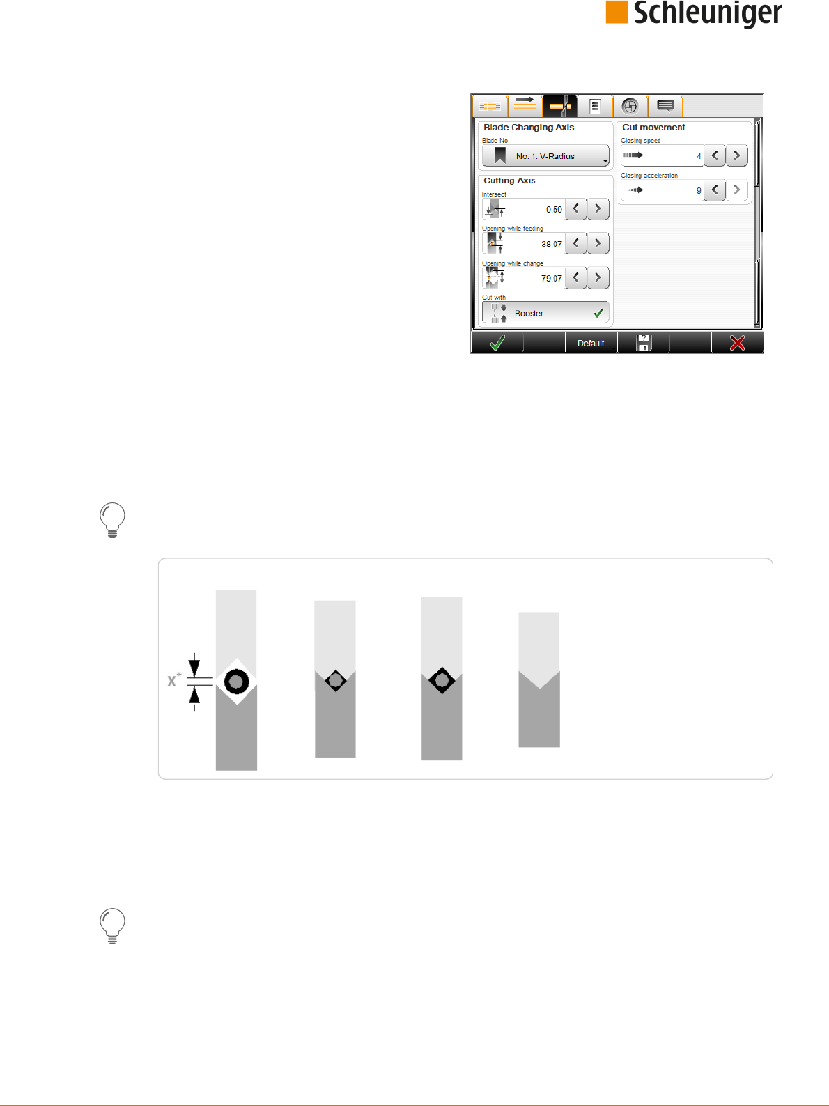
8. Standard process ow
Reference Manual | Edition 9.0 (03-2021) |
S.ON
73 | 214
Blade changing axis
Blade no.
This denes the blade type used and the blade
position. Here the selection of the blades
assigned to the MultiStrip 9480 with its associ-
ated position can be selected.
Cut movement
Closing speed / closing acceleration
These settings change the speed and the accel-
eration of the cutting movement, whereas 0 is
the smallest and 9 the largest selectable value.
Cutting axis
Intersect
Depending on the type of blade and the material being processed, the blades intersect when cutting
through the raw material (standard value is 0.5 mm). This traversing path can be dened here.
Opening while feeding
During feeding, the blades return to their dened reference position.
This value must be suciently large enough to ensure that the raw material is not damaged during
feeding. On the other hand, the position should not be unnecessarily large or the blade movements
will take too long.
Reference setting
Incising
Wayback
Cut
Fig. 10: Position of blades while feeding
*) With a blade change, the blades open to the value: X > raw material diameter
Opening while change
Denes the blade opening during a blade change. This is the reference position during the raw mate-
rial feeding.
It is important that this value is selected large enough, otherwise the raw material will jam and the
blades may break.
Cut with booster activate
Optionally a pneumatic cutting unit booster is available. Here it can be activated. With large diame-
ters (> 150 mm
2
), it supports the cutting unit with additional force to the cutting axes. This ensures a
precise cut.
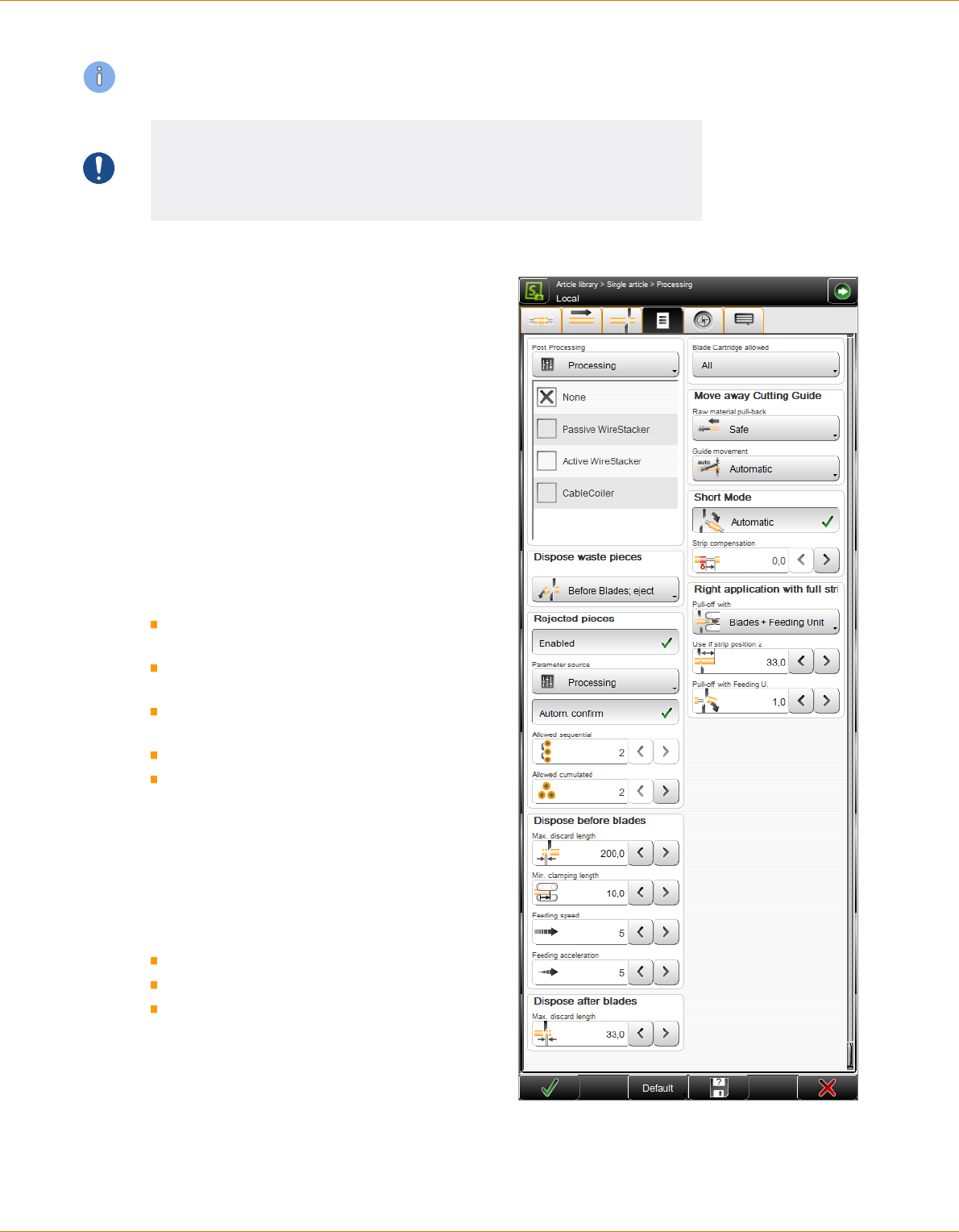
8. Standard process ow
74 | 214
Reference Manual | Edition 9.0 (03-2021) |
S.ON
The maximum cutting speed should therefore be set to not higher than 5 (optimal cutting speed = 1).
NOTICE
Property damage!
The raw material can be squeezed and there is a danger to break the blades.
The blades must necessarily open far enough.
8.5.6
Options
Post-processing
Denes the source for the post processing.
Conguration
Here the Post Processing device is controlled
basically by the „Conguration“. The settings
made in the "Conguration" are used.
Processing
This denes which post-processing devices are
acceptable for the production. To be able to start
the production, one of the selected devices must
be set as the active post-processing device in the
"Setup".
The following settings are available:
None: The production shall be carried out
without a post-processing device.
Passive wire stacker: A passive wire stacker
shall be used.
Active wire stacker: An active wire stacker
shall be used.
Cable coiler: A cable coiler shall be used.
User dened device: A user dened device
is congured and shall be used.
Dispose waste piece
During processing, the stripped insulation piece
sometimes gets stuck in the stripping area.
There are three dierent ways to remove the
waste piece:
Normal
After blades; cut
Before blades; eject
Normal
The waste piece is ejected uncut after the
blades.

8. Standard process ow
Reference Manual | Edition 9.0 (03-2021) |
S.ON
75 | 214
After blades; cut
If this setting is enabled, the blades shred the waste piece after the cutting process. Thereby the opti-
mal process reliability is guaranteed compared to the third setting, while blade wear is somewhat
greater.
Before blades; eject
Prevents the waste piece or parts thereof from remaining in the good parts. The process reliability is
less well with this setting, the blade wear is rather low.
Dispose before blades
Maximum discard length: The waste piece is cut into parts and then ejected before the blades. This
denes the maximum length of each piece to be cut.
Minimum clamping length: Denes the minimum length, where the waste piece is just clamped.
Feeding speed/-acceleration: Denes the feeding speed/-acceleration the material is fed with dur-
ing processing.
Allowable cartridge
This setting depends on the used MultiStrip 9480 model.
All
All blade cartridges from the conguration may be used.
Dening selection
Only blade cartridges from the drop-down list must be used for the actual Processing.
Add cartridge (+): Add a blade cartridge dened in the conguration to the local list.
Delete cartridge: Delete a selected blade cartridge from the local list.
Option Rejected pieces
Activated: Enables the function for sorting out defective pieces. The “SmartDetect” monitoring func-
tion must be activated in the conguration.
Parameter source: Conguration (the conguration settings apply) or procedure. If “Processing” is
selected, the “Automatic conrmation” key appears.
Automatic conrmation: The input elds "Allowed sequential" and "Allowed cumulated" are availa-
ble for counting the allowed contacts of the blade with the conductor. See also chapter "7.11.3.3 Limi-
tation of number of errors (Page 53)".
For further information see chapter "7.11.1 “SmartDetect” (Page 49)" and "7.11.3 Disposal of rejected
pieces (Page 51)".
Move away cutting guide
Dene the wire pull-back method for the right strip.
Raw material pull-back
Safe: The raw material rst is pulled back to a dened value and then the swivel guide moves up.
Fast: The raw material is pulled-back for a predened value and simultaneously the swivel guide
moves up (fast production, works in most cases with short articles).
Safe/length: The raw material is pulled back for the dened value "Pull back length" and then the
swivel guide moves up.
Set pull-back length
Denes the pull-back length in the left guide. This option can be used to prevent a bend of the raw
material when the swivel guide moves up (the measure 134 mm corresponds to a complete with-
drawal from the guide for models with swivel guide).
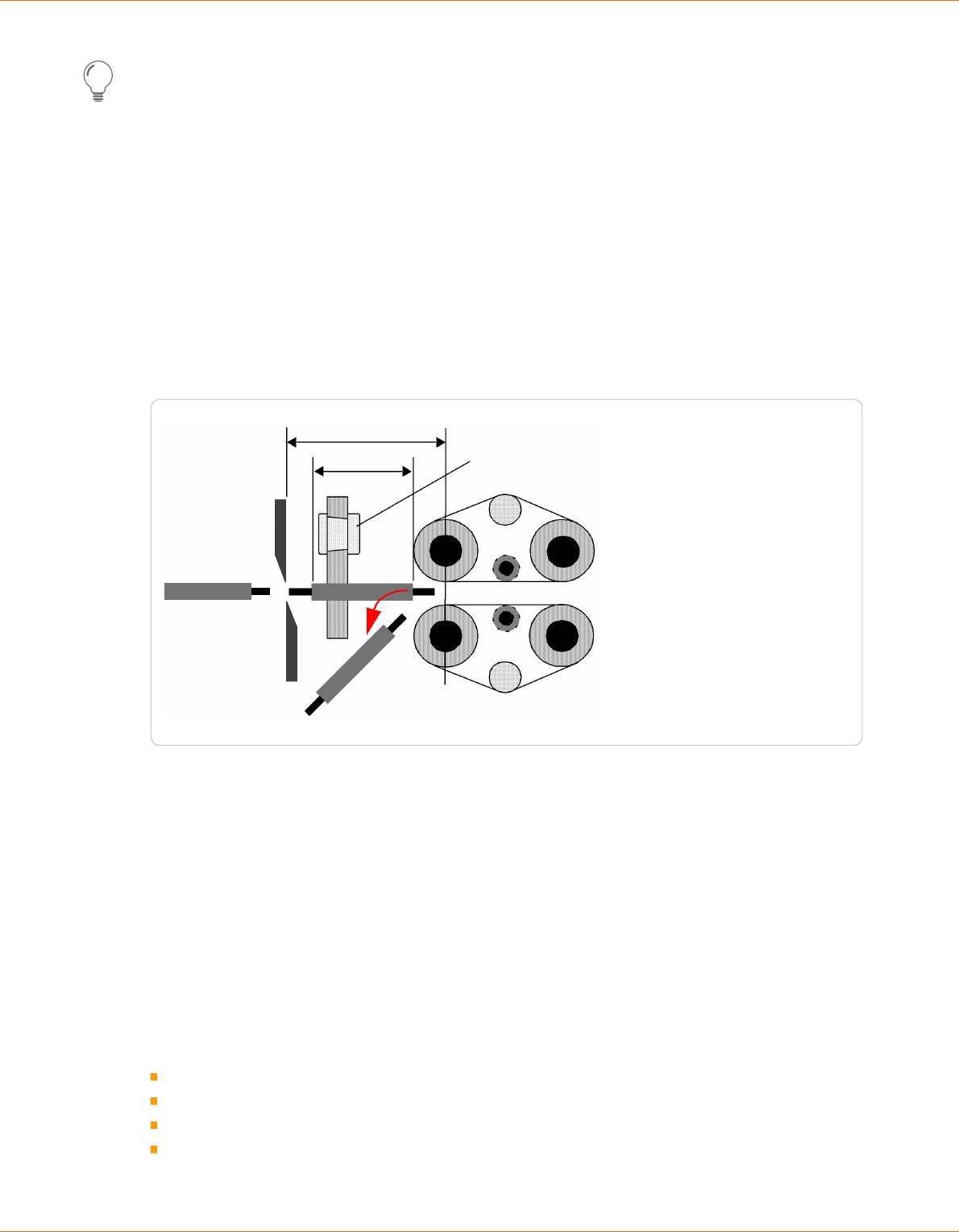
8. Standard process ow
76 | 214
Reference Manual | Edition 9.0 (03-2021) |
S.ON
This option is suitable for the treatment of rigid raw materials.
Guide movement
Denes the method for the guide movement for the left partial-/full strip.
Automatic: The method is dened automatically.
Manual: The guide movement is executing according to the measure in "Movement way” (MultiStrip
9480 only).
O: The guide does not move during the left partial-/full strip.
Movement way
Denes the swivel range from the center of the wire to the center of the guide.
Short mode
The "Short mode" settings can be invoked either automatically or manually.
Distance: Blades + feeding unit
54
The short piece of article is ejected between the right feeding belts and the blades
The linear guide is moved out
Fig. 11: Short mode
Automatic
If after processing the slug on the article is shorter than the value calculated by the machine, the
"Short mode" is activated. Production in "Short mode" concludes to all operations from the left side to
be integrated to the right side. The linear guide is moved out of the wire axis and the right feeding
belts open to the value "Guiding gap" (processing - feed). Then the produced article is ejected
between the blades and the right feeding belts out of the machine.
Manual
While invoking the "Short mode" manually, the behavior of the MultiStrip 9480 can be determined
exactly.
Left application - converting activate/deactivate Denes if the operations of the left side are to be
converted to the right side. Certain requirements must be fullled for the conversion, otherwise an
error message occurs:
Only "Strip mode" used
Direction, to the end
Same layers and branches
No "Strip with window" operations

8. Standard process ow
Reference Manual | Edition 9.0 (03-2021) |
S.ON
77 | 214
Guide position while feeding - Retracted activate/deactivate: Denes the behavior of the guide
before the right feeding unit. Either it is "Retracted" or it acts "Automatically". The guide is moved out
of the wire axis.
Strip compensation
Because of executing the left side strip to the right hand side of the article, it can occur that the insu-
lation gets stretched slightly during production. This sometimes causes a small piece of insulation to
be left over on the left end of the material. To prevent this, a value greater than zero can be entered in
the „strip compensation“ eld. All the left stripping is shifted to the left by this value.
This compensation is available in "Short mode - Auto“ as well as in „Manual".
Right application with full strip
Denes the pull-o method for the right full strip. Full strips on the right end must be specially trea-
ted, since depending on length the slug can jam between the blades and the right guide respectively
the right feeding unit. To prevent this, the slug can be pulled o and ejected by the right feeding unit.
Pull-o with - blades
The full strip takes place without the assistance of the right feeding belts.
Slug
Fig. 12: Right full strip with blades only
Pull-o with - blades + feeding unit
Use if strip position >: Denes the minimal stripping length in the active mode. If the full strip is
larger than the length selected here, the slug is pulled o and ejected by the right feeding unit - oth-
erwise the stripping is done without the help of the right feeding unit.
Pull-o with feeding unit: Denes the maximal pull-o length with feeding unit. This is the part of
the stripping, which is performed by the feeding unit.

8. Standard process ow
78 | 214
Reference Manual | Edition 9.0 (03-2021) |
S.ON
Slug
Fig. 13: Right full strip by blades + feeding unit
8.5.7
Rotary incising unit
If the MultiStrip 9480 is equipped with a rotary incising unit, general settings for the rotary cut can be
made here.
Rotary movement
Speed / acceleration
Denes the rotational speed and acceleration
over a range from 0 to 9.
Rotary incising unit
Distance correction
Here small raw material specic oset correc-
tions of the rotary incising unit position can be
made.
Guided correction
Also a menu guided correction can be carried
out. For this an article must be programmed
which has been stripped with the rotary incising
unit. See also Chapter "8.5.4.2 Resolution correction (Page 71)".
Rotary incising axis
Opening while feeding
The blades of the rotary incising unit close to this opening diameter while feeding the raw material.
Centering axis
Speed / acceleration
Denes the traversing speed and acceleration of the centering over a range from 0 to 9.
Pressure
Denes the closing pressure force of the centering axis.
Opening while feeding
During feeding, the centering opens to the corresponding set value.

8. Standard process ow
Reference Manual | Edition 9.0 (03-2021) |
S.ON
79 | 214
8.5.8
Comment
Here a comment can be entered when the Pro-
cessing has to be changed. This can be switch-
ed on or o in the "Conguration - Produc-
tion“ settings.
If an article list has to be produced, the com-
ments can be globally switched on or o.
Via the keys below the comment eld, the
blade conguration and/or the connected post-
processing device settings can be taken over
into the comment eld.
8.6
APPLICATION EDITOR
8.6.1
Overview
As soon as an application type has been selected, the application editor can be opened by touching
the respective pictogram. Here additional details to the article can be entered (stripping length, pull-
o length and others). Depending on the application type, more or less operation steps (operations)
are available.
Operation 1
Operation 2
6
5
4
3
2
1
1
Tab
1
2
Position
3
Slitting option
4
Length
5
Save as local Processing element
6
Processing element of this operation
1
) - here the user can select between left, right and area application.
8.6.2
Description
Processing step (operation)
Here the operation types stripping (jacket/inner conductor), slitting, comb or window are shown.
Position
Describes the start position of this operation e. g. the stripping position or the start of the slitting.

8. Standard process ow
80 | 214
Reference Manual | Edition 9.0 (03-2021) |
S.ON
Slitting option
This switches the slitting operation on or o. Additionally if the slitting operation is switched on, it can
be dened if the slitting takes place before or after stripping.
Length
Describes the length of the operation element, e. g. the length to be slit.
Save as local processing element
Switch on/o, saving as local Processing element. If this is switched to "Normal", the operation is per-
formed the same as for the rest of the article. If local Processing element is selected, the values
entered in this operation step column are stored locally in the operation.
Processing element of this operation
This shows the corresponding Processing element of the operation, the values can be edit directly in
the element column.
8.6.3
Partial- and full strip
Operation 1: Describes in this order the values
for the right and left end:
Stripping (10.0 mm)
Pull-o (5.0 mm)
Operation 2: Denes in this order, if the insula-
tion is to be slit and if so, if this is carried out
before stripping or after:
The start position of the slit (10.0 mm)
The length of the slit (5.0 mm)
8.6.4
Window strip
Operation 1/2: The operation 2 is known from
the previous partial strip. The operation 1
denes in this order the stripping of the win-
dow:
The start position of the window strip
(30.0 mm)
The length of the window (5.0 mm)
8.6.5
Multi layer cable
Operation 3
Operation 2
Operation 1
Operation 1: Denes in this order the full- or partial strip of the jacket:
Operation 2
Operation 1
Operation 2
Operation 1

8. Standard process ow
Reference Manual | Edition 9.0 (03-2021) |
S.ON
81 | 214
Stripping length (30.0 mm)
Pull-o length (35.0 mm)
Operation 2: Denes in this order the full- or partial strip of the intermediate layer:
Stripping length (20.0 mm)
Pull-o length (25.0 mm)
Operation 3: Denes in this order the full- or partial strip of the dielectric:
Stripping length (10.0 mm)
Pull-o length (15.0 mm)
Under "Operation order" the stripping order during processing can be changed. This depends on the
nature of the raw material and aects also the production speed.
8.6.6
Multi conductor cable
Operation 3
Operation 4
Operation 2
Operation 1
Operation 1: Denes in this order the full strip of the jacket:
Stripping length (10.0 mm)
Pull-o length (15.0 mm)
Operation 2: Consists of only one value and denes the start position of the combing.
Operation 3: Denes the stripping of the inner wire in this order:
Stripping length (8.0 mm)
Pull-o length (6.0 mm)
Operation 4: Denes the slitting, as has already been described in part/full strip.
8.6.7
Flat ribbon cable
Operation 3
Operation 4
Operation 2
Operation 1
Operation 1: Denes the separation of the wires:
Position (50.0 mm)
Length (55.0 mm)
Operation 2: Denes the stripping of the rst inner wire in this order:
Stripping length (40.0 mm)
Pull-o length (5.0 mm)
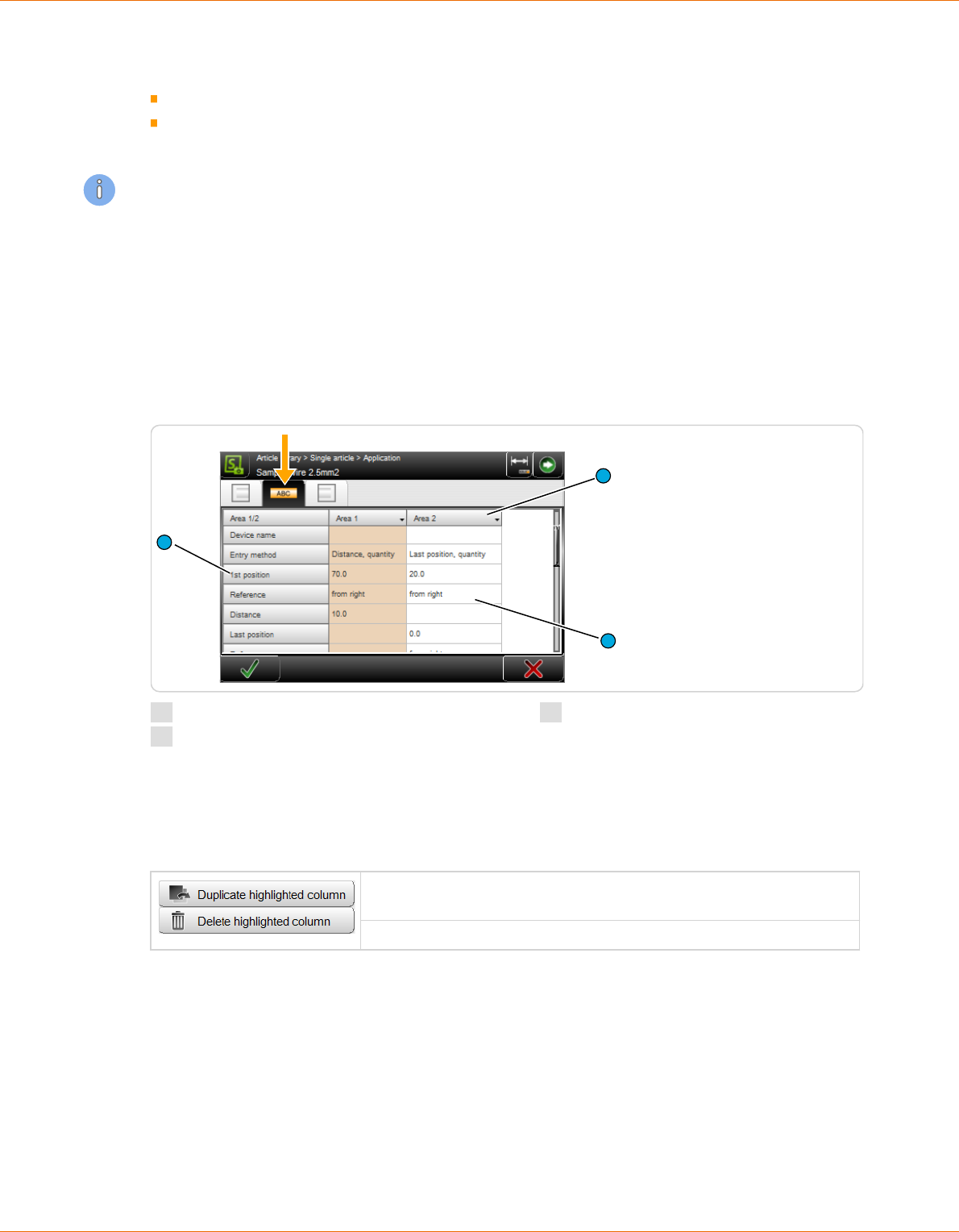
8. Standard process ow
82 | 214
Reference Manual | Edition 9.0 (03-2021) |
S.ON
Operation 3: Denes the stripping of the second inner wire in this order:
Stripping length (20.0 mm)
Pull-o length (5.0 mm)
Operation 4: Consists of only one value (30.0 mm) and denes the shortening of the conductor.
Additionally, under operation 4, it can be dened if shorten takes place on the upper or lower con-
ductor.
8.7
APPLICATION EDITOR AREA
Areas are meant for marking the wire with a HotStamp, Inkjet printer or thermal transfer printer. An
article can be marked with many individual texts on dierent positions.
8.7.1
Screen overview
By touching the area zone in the article editor the area editor shows up where areas (article labeling)
are programmed. First an overview is shown, where all area columns with settings are listed.
3
1
2
1
Header line area column
2
Editable area
3
Description of area
Header line area column
By touching the header section of an area column, a drop-down list is displayed, where areas are
duplicated or deleted.
An additional area column with all previous values is created. It can
then be edited.
The selected area is deleted.
The user can use dierent marking devices simultaneously. Therefore an additional area screen is pro-
vided for each marking device or in case of marking a wire measured from the left or the right end. All
settings e. g. position or quantity can be independently set in each area.
Editable area
Touching any value eld in the overview column, opens the entry mask, where the settings can be
altered.

8. Standard process ow
Reference Manual | Edition 9.0 (03-2021) |
S.ON
83 | 214
Description of the area
Display of description for the area column.
8.7.2
Area settings
Device type
Select the device type for this area. None, Hot-
Stamp, Inkjet- or thermal transfer printer is
available here by default.
The selection of the device depends on the
conguration of the wire processing line.
None: Is used for temporarily deactivate the
area application.
The setting "None" can be used when no mark-
ing device is used, but the programmed posi-
tions of the areas shall not be lost. The
MultiStrip 9480 would not permit production
with a device set in an area, but physically not
present.
HotStamp: Marking the article by use of a hot
stamp unit. A wire marker device must be connected therefore.
Inkjet-/thermal transfer printer: Marking the wire with an Inkjet- or thermal transfer method printer.
A thermal transfer printer can only be used with CAYMAN. Settings for the font properties are only
displayed if "Inkjet" is set.
Device name
User dened device name if using customer specic marking devices.
Entry method
Select the repeat method for this area. To dene the area clearly, only two of the three possible selec-
tions (Distance, last position / quantity / last position, quantity) have to be set. The program calculates
the third parameter automatically from the two entered parameters.
If the entry method is switched over, the disabled entry eld is enabled and the next one disabled.
The values are retained.
1. Position
Last position (from left / from right)
Distance
1
4
3
2
Quantity of markings
Fig. 14: Positioning of areas
1st position
Sets the position of the rst repetition The position of the rst marking is measured towards the end.

8. Standard process ow
84 | 214
Reference Manual | Edition 9.0 (03-2021) |
S.ON
Reference
Toggle the referencing end (left or right). From left or from right can be selected here.
Distance
Sets the distance between two repetitions.
Calculation formula:
Distance =
(last position - first position)
(Quantity - 1)
Last position
Sets the position of the last repetition.
Calculation formula:
Last position (from left / from right) = 1. position + (quantity - 1) × distance
Reference
Toggle the referencing end (left or right). From left or from right can be selected here.
Quantity
Sets the quantity of repetitions.
Calculation formula:
Quantity = 1 +
(last position - first position)
Distance
With the entry method „Distance, last position” the last position is only printed if it meets exactly the
position „rst position + (quantity -1) x distance". E. g. this means the last position is the max. allowa-
ble position.
Text
Entry of the text to be printed on the article. The appearance of the text can be individually arranged
with tags. Also variables like time and date can be dened.
The options to be used for the text entry are depending on the device type:
Device type
None The text eld is grayed-out
HotStamp With the HotStamp device, this input serves only for the representation
on the screen and as a demand to set the correct text on the HotStamp,
since with the HotStamp the text to be printed has to be set manually.
To do so a stop condition can be selected.
Inkjet printer The Inkjet printer receives this text directly from S.ON and marks the
article with this. Following to text entry eld additional elds for the
font face are available.

8. Standard process ow
Reference Manual | Edition 9.0 (03-2021) |
S.ON
85 | 214
Device type
Thermal transfer printer With the thermal transfer printer device, this input serves only for the
representation on the screen or for the transfer to the wire processing
software CAYMAN, since with the Thermal transfer printer the text to be
printed has to be set manually or via CAYMAN. Here no text properties
(font type, font size) are shown.
Dened text
During the text entry additional predened variable elds (tags) can be entered on dierent positions
of the text. For this, the cursor must be positioned in the text entry eld on the desired position.
To enter a standard Schleuniger tag, select the appropriate tag in the drop-down list. The tag then
appears in the text eld with a leading "@" symbol.
The following predened elds are available:
Time @1: Prints the actual system time in the for-
mat pre-dened in the „Conguration“.
Date @2: Prints the actual system date in the for-
mat pre-dened in the „Conguration“.
Custom time \&TH:M\&: Prints the actual time in
a format which can be dened by the user itself.
Custom date \&DD:M:Y\&: Prints the actual date
in a format which can be dened by the user itself.
Quantity produced @3: Counts the number of
already produced articles.
Batch produced @4: Counts the number of
already produced batches.
Counter @5: Uses the entry eld "Start Counter".
Toggle bold @6: All following letters are shown in bold/normal.
File name @7: Prints the actual article name dened in the library.
Tags can also be entered without the "@" key directly into the text eld.
There are limitations in the use of the @3, @4 and @5 tags in connection with rejected pieces.
There are also additional "Simple tags" available, but they can only be used on specic printers:
Tag Meaning Printer model
\#A Logo-Index A (one capital letter following to \#) Wiedenbach
\#B to \#Z Logo-index B (C,D,E etc.) Wiedenbach
\#L Align text left Brady Wraptor
TTP 4000
\#R Align text right Brady Wraptor
TTP 4000
\#C Align text centered Brady Wraptor
(not TTP 4000)
Additional tags are available for the bar code display and others. These also are only available on spe-
cic printers. A start tag must always be terminated with an end tag „\&“. In between the appropriate
information is entered.

8. Standard process ow
86 | 214
Reference Manual | Edition 9.0 (03-2021) |
S.ON
Tag Meaning On printer Interpreted in
Inkjet DLL
Interpreted In
CAYMAN device
connector
Not supported
\&1 Barcode 39 Wiedenbach Metronic Alpha
Jet C & Evo
Brady Wraptor
TTP 4000
Imaje, Domino
\&2 Barcode 2/5
interleave
Wiedenbach Metronic Alpha
Jet C & Evo
Brady Wraptor
TTP 4000
Imaje, Domino
\&3 Barcode EAN13 Wiedenbach Metronic Alpha
Jet C & Evo
Brady Wraptor
TTP 4000
Imaje, Domino
\&4 Barcode 128 Wiedenbach Metronic Alpha
Jet C & Evo
Brady Wraptor
TTP 4000
Imaje, Domino, Met-
ronic Alphajet Evo
only capital letters
allowed.
\&5 Barcode EAN128 Wiedenbach Metronic Alpha
Jet C & Evo
Brady Wraptor
TTP 4000
Imaje, Domino, Met-
ronic Alphajet Evo
only capital letters
allowed.
\&6 Barcode UPC-A
(=UPC12)
Wiedenbach Metronic Alpha
Jet C & Evo
Brady Wraptor
TTP 4000
Imaje, Domino
\&7 Barcode Pharma
(=PZN)
Metronic Alpha
Jet C
Brady Wraptor
TTP 4000
Imaje, Domino, Wie-
denbach, Metronic
Alpha Jet Evo
\&8 Barcode EAN8 Metronic Brady Wraptor
TTP 4000
Imaje, Domino, Wie-
denbach
\&9 Barcode UPC-E
(=UPC8)
Metronic Alpha
Jet C & Evo
Brady Wraptor
TTP 4000
Imaje, Domino, Wie-
denbach
\&a Barcode
EAN128C
Metronic Alpha
Jet C & Evo
Imaje, Domino, Wie-
denbach
\&b Barcode EXT-2
(=EAN-2)
Metronic Alpha
Jet C & Evo
Imaje, Domino, Wie-
denbach
\&c Barcode EXT-5
(=EAN-5)
Metronic Alpha
Jet C & Evo
Imaje, Domino, Wie-
denbach
\&d Barcode Coda-
bar
Metronic Alpha
Jet C & Evo
Brady Wraptor
TTP 4000
Imaje, Domino, Wie-
denbach
\&D User-dened
date
Imaje, Metronic,
Wiedenbach
\&F File name of a
bitmap/logo
Coditherm Metronic Alpha
Jet C & Evo
Brady Wraptor
TTP 4000
\&T User-dened
time
Imaje, Metronic,
Wiedenbach
\&m Data matrix (2D-
code)
Brady Wraptor
TTP 4000
\&q QR-code Brady Wraptor
TTP 4000
\&z Aztec (2D-Code) Brady Wraptor
TTP 4000

8. Standard process ow
Reference Manual | Edition 9.0 (03-2021) |
S.ON
87 | 214
Tag Meaning On printer Interpreted in
Inkjet DLL
Interpreted In
CAYMAN device
connector
Not supported
\&L Layout of label Brady Wraptor
TTP 4000
\&S Scaling of label
element
Brady Wraptor
TTP 4000
\&n New line Brady Wraptor
TTP 4000
\& End of printout (end tag)
Counter start value
Denes the start value of the eld "Counter start". As the name states, this counter is increased by 1
after each produced article.
Font format
Here the font type and size can be entered.
These elds, with the exception of the font col-
or, are only displayed for printer types “Inkjet,
Laser, Thermal transfer".
Font size: The selected font size is submitted to
the printer, where the printing can be executed
in this size.
Only enter font sizes which are supported also
by the printer! Common sizes are 5, 7, 11(12) and 15(16).
Font color: To let S.ON know in which color the printer shall be printing, this is dened here addition-
ally (only serves for the display in CAYMAN „WYSIWYG“ -> What you see is what you get).
If more articles with dierent colors have to be marked with the HotStamp, the sealing sheet device
must be changed there. A stop condition can be dened for this purpose.
With a text or color change, an appropriate message is shown if in the article list - Properties, „Adapt
HotStamp” is set to „Message”.
Bold: The text will be highlighted.
Tower font: The individual letters of the text are rotated by 90°.
Horizontal/vertical mirrored: The text is displayed mirrored.
Font properties: In these elds the user can switch on or o additional font properties but they are
only helpful if they are supported by the connected printer device.
To make a single word or a letter to be shown in bold, select „@6 Toggle bold“.
The font properties are always set for the complete font operation.
8.8
RAW MATERIAL EDITOR
In S.ON a xed selection of programmed Raw materials for selection is available for the standard proc-
ess ow.
8.8.1
Overview of standard Raw Materials
The chart gives an overview of the Raw materials. The Raw material name in the left column is
reserved.
Self dened Raw materials (dened in "Library mode") cannot be saved under this names.

8. Standard process ow
88 | 214
Reference Manual | Edition 9.0 (03-2021) |
S.ON
Description Denition
Diameter Here, the user determines the
inner
1
- and outer diameter
2
itself. When invoking the direct
measurement, the inner and
outer diameter measure, is
graphically shown.
2
1
AWG solid Raw material is dened as American Wire Gauge solid wire.
AWG stranded Raw material dened as "American Wire Gauge" with stranded wire.
mm
2
solid
Raw material dened as conductor diameter in mm² with solid wire.
mm
2
Raw material dened as conductor diameter in mm² as stranded wire.
Multi layer Here the user determines the
diameters himself. When invok-
ing the Raw material "Multi-lay-
er", the measurements to be
typed in are represented graphi-
cally.
1
Jacket-Ø
2
Outer Ø shield
3
Outer Ø insulation
4
Conductor Ø
2
4
3
1
Multi conduc-
tor
Here the user determines the
diameters himself. When invok-
ing the Raw material "Multi-con-
ductor", the measurements to
be typed in are represented
graphically.
1
Jacket-Ø
2
Inner-Ø
3
Outer Ø insulation
4
Conductor Ø
2
4
3
1

8. Standard process ow
Reference Manual | Edition 9.0 (03-2021) |
S.ON
89 | 214
Description Denition
Flat ribbon Here the user determines the
diameters himself. When invok-
ing the Raw material "Flat rib-
bon", the measurements to be
typed in are represented graphi-
cally.
1
Outer Ø insulation
2
Conductor Ø
1
2
Raw material selection
See Chapter raw material type "8.9.6 Raw material type (Page 91)".
8.9
INIT
Denes basic settings for the article. When a new article has been invoked, after entering the product
name this screen is automatically called and the setting "Create with Data Sheet" is selected.
4
6
7
8
9
5
1
2
3
1
Convert to library
2
Raw material data
3
Processing data
4
Application right
5
Application swap
6
Application left
7
Wire dimension
1
8
Raw material type
9
Single article creation type
1
) - only Raw material types: mm2 or AWG
8.9.1
Convert to library
Saves the local Raw material and Process data in new libraries. After touching the button, the dialog is
displayed where the library entries can be assigned a le name.

8. Standard process ow
90 | 214
Reference Manual | Edition 9.0 (03-2021) |
S.ON
For further information on this type of processing type, "Library mode", see Chapter "9 Library mode
(Page 95)"
8.9.2
Raw material- / Processing data
By default here for the "Standard process ow", "Local" is displayed. The Raw material and Processing
data are stored locally in the article.
If "Create with links from library” is selected, the Raw material and Processing data can also be
obtained from the libraries. From which library the data are obtained, is displayed here.
8.9.3
Application left / right
Denes the method, how the left and/or right end (application) shall be produced. The drop-down list
only shows the ends depending on the type of certain Raw material and which production mode the
user is working in (standard process ow, library-, article list mode). There are dierent applications,
which depending on the Raw material type, save a lot of programming steps. Be sure to select the
method best suited for the current Raw material, respectively the current task. Steps are generated
depending on the quantity of layers of the material.
Not all application types can be used with all Raw materials. The following illustration gives an over-
view:
Raw material types Possible applications
Diameter, AWG solid, AWG stran-
ded, mm2 solid, mm2 stranded
Multi layer
Multi conductor
Flat ribbon
Tab. 3: Raw material types and applications
For further information to the applications, see Chapter "8.3.4 End application left / right (Page 62)".
8.9.4
Swap application left/right
Exchanges the left end with all its end application settings with the right one and vice versa.

8. Standard process ow
Reference Manual | Edition 9.0 (03-2021) |
S.ON
91 | 214
8.9.5
Wire dimension
This setting is only available for the raw material types "mm2" and AWG. Here the dimension of the
used Raw material is dened. This is a measure which informs the MultiStrip 9480 how far the feeding
belts shall close after loading the raw material. This measure also helps in the calculation of default
values for the Processing.
The eld will be shown dierently depending on the measuring type:
Raw material type Description Illustration
mm
2
The data are entered directly via the numeric touch-
keyboard or via the arrow keys of the spin box.
AWG The value is selected directly from the drop-down list.
For the other raw materials the wire dimensions are set in the Raw material editor.
For this proceed as follows:
1.
▹
In the “Init” screen touch [OK].
➥ The “Single article” editor is shown.
2.
▹
Select [ROHMATERIAL EDITOR].
3.
▹
Set the values accordingly.
4.
▹
[OK]
See also Chapter "8.8 Raw material editor (Page 87)".
8.9.6
Raw material type
Denes the Raw material types available in the MultiStrip 9480 which can be processed.
In the "Init" screen, on "Standard process ow", the following Raw materials are available:
Diameter
AWG solid
AWG stranded
mm2, solid
mm2 stranded
Multi layer
Multi conductor
Flat ribbon
For further information, see Chapters "8.9.3 Application left / right (Page 90)" and "8.8 Raw material
editor (Page 87)".
8.9.7
Single article - creation type
Here the initial situation is selected, with what the user begins, in order to create a single article.

8. Standard process ow
92 | 214
Reference Manual | Edition 9.0 (03-2021) |
S.ON
Fig. 15: Single article - creation type
Create with data sheet: Dimensions are taken from the wire data sheet. If settings are already
present, the values will be reset to default by this command.
Create with links from library: An existing Raw material and Processing is selected from the
library and is used as a template.
Edit current: The article is edited with existing settings.
8.10
AUTONOMOUS PROCESSING ELEMENT
A Processing element can be normal or autonomous. An autonomous element is independent of the
standard Processing element in 1 operation, thus autonomous.
1.
▹
Choose the option [AUTONOMOUS] in the
application editor.
2.
▹
In the Processing editor, the autonomous
element is marked with a white "i" on a blue
background.
When adaptively recalculating the default values, all autonomous elements are recalculated
adaptively.

8. Standard process ow
Reference Manual | Edition 9.0 (03-2021) |
S.ON
93 | 214
When completely recalculating the default values from the settings or from the raw material edi-
tor, the autonomous elements are deleted. The corresponding warning message indicates that
the elements will be deleted, if any are present.
On the other hand, the autonomous elements are not deleted from the Processing editor during
the calculation.
See also chapter "8.11 Recalculation default values (Page 93)".
8.11
RECALCULATION DEFAULT VALUES
Processing values are based on raw material, machine type and conguration.
New local Processings are automatically created with the default values of the associated raw materi-
al. The processing can be opened and adapted in the single article editor or via the editor application.
If the raw material is subsequently changed in the default settings, the processing is recalculated
completely, adaptively (i. e. taking into account the previous adjustments in the process) or not at all,
if desired.
See also chapter "8.5.2 Default (Page 66)".
The following warning appears:
When changing raw material, it is recommended to calculate the default values.
[OK]: Really calculate processing default values adaptively (recalculates raw material diameter
depending values only and takes previous changes to those values into account)?
[ALL]: Calculate processing default values for entire processing (existing autonomous processing
elements are deleted), "Page 92".
[NONE]: Do not change any processing value.

8. Standard process ow
94 | 214
Reference Manual | Edition 9.0 (03-2021) |
S.ON
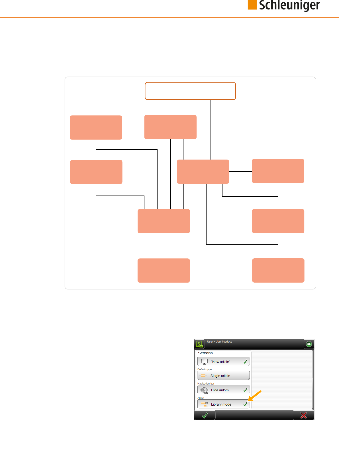
9. Library mode
Reference Manual | Edition 9.0 (03-2021) |
S.ON
95 | 214
LIBRARY MODE
To be able to use this mode the correct way it is essential to study the Chapter "8 Standard process
ow (Page 59)" rst. Here only the functions which dier from the “Standard process ow” or added
new functions are described.
Application editor
Processing editor
Start of machine
Application editor area
Init
Article library
Single article editor
Application
Raw material library
Processing library
Raw material editor
Fig. 16: Principle, "Library mode"
9.1
ACTIVATING LIBRARY MODE
In order to use the library mode, it must rst be enabled under “User”.
1.
▹
NAVIGATION
2.
▹
[USER]
3.
▹
[USER INTERFACE]
4.
▹
Under "Screens - Allow", activate [LIBRARY
MODE].

9. Library mode
96 | 214
Reference Manual | Edition 9.0 (03-2021) |
S.ON
The "Library mode" provides additionally the
application type called “User dened". This way
also multi-step stripping can be performed.
What ends are displayed, depends on the used
raw material.
The command “Default” to calculate the Processing values based on the Raw material is not available
in this form in the “Library” mode.
During changing from "Standard process ow" to "Library mode" a library Raw material can be saved
from the standard Raw material. The values are taken over from the simple Raw material. The follow-
ing message is shown: “Save current raw material data in a new library le?". The same applies to the
Processing data.
9.2
CREATE NEW ARTICLE
A new article in the ”Library mode” can be created in two dierent ways.
Transform an existing article programmed in standard process ow to “Library mode” and gener-
ate new records in the Raw material and Processing library.
Link a new or existing article with existing records from the Raw material and Processing library.
9.2.1
Convert an existing article
For this procedure, the Raw material and Processing library can be still empty.
1.
▹
Call existing article, programmed in standard process ow, in the single article editor.
2.
▹
Go to the “Init” screen.
3.
▹
On „Single article“
1
, set „Edit current arti-
cle“.
4.
▹
Set „Convert to library“
2
.
➥ The Raw material library is opened, where
a new name can be entered. Then the
Raw material is stored in the library.
5.
▹
[OK]
➥ The Processing library is opened, where a
new name can be entered. Then the Pro-
cessing is stored in the library.
6.
▹
[OK]
➥ The single article editor is displayed where the article is programmed to the end.
9.2.2
Link new / existing article with library data sets
In order for this approach to work, already records should be stored in the Raw material and Process-
ing library.
21

9. Library mode
Reference Manual | Edition 9.0 (03-2021) |
S.ON
97 | 214
1.
▹
Create a new article in the article library, or
call an existing one.
➥ The “Init” screen is opened.
2.
▹
On „Single article“
1
, set „Create with link
from library“.
3.
▹
Under „Raw material data“
2
select the
appropriate Raw material.
4.
▹
Under „Processing
3
“ select the appropri-
ate Processing or take over the linked pre-
ferred Processing (saved in the Raw materi-
al).
5.
▹
Select the corresponding end applications
for the right and possibly left end
4
.
6.
▹
[OK]
➥ The single article editor is displayed and the further stripping parameters can be programmed.
9.3
SINGLE ARTICLE EDITOR IN THE LIBRARY MODE
The following screen shows the single article editor in “Library mode”. In the content area, the Raw
material and the Processing associated from the corresponding libraries are displayed. Raw material
and Processing values can be changed directly in the corresponding editors.
1
2
1
Raw material library
2
Processing library
In the navigation bar there are two new entries which direct to the Raw material and Processing libra-
ries.
1
2
3
4

9. Library mode
98 | 214
Reference Manual | Edition 9.0 (03-2021) |
S.ON
The les can also be edited there:
9.4
RAW MATERIAL LIBRARY
The initial products - that is to say raw materials, introduced to the MultiStrip 9480 - are saved in the
Raw material library as records. These records describe how an article is made up (e. g. a Power cord or
a at cable). This includes the type (e. g. Ribbon cable or twisted pair cable).
This describes the Raw material composition divided in layers. This gives an understanding to the
MultiStrip 9480 what it processes. For example it can check via the outer diameter if the correct raw
material is loaded, or it knows how many layers can be stripped (thus if it is a stranded wire, only layer
2 or a multi-conductor cable, where the layers 2 or 3 can be stripped).
If a le in the library is changed, all wires linked to this Raw material are changed instantaneously
without any extra action.
In the Raw material library, alternatively to the le management, there is also the ability to manage
Raw material les independently from articles and article lists.
9.4.1
Raw material library, list view
1
2
1
File options
2
Import le
For the description of other elements in the Raw material list, see Chapter "7.7 Data management
(Page 43)".
File options
Here, more le manipulation commands for the Raw material are available.
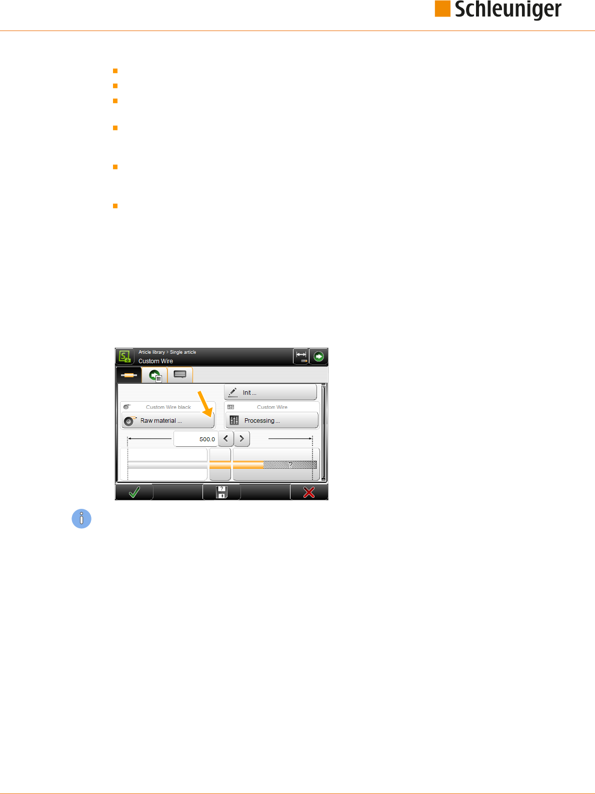
9. Library mode
Reference Manual | Edition 9.0 (03-2021) |
S.ON
99 | 214
Duplicate highlighted le: For an existing saved le, a copy with the same settings is created.
Rename highlighted le: Changes the le name of the selected le.
Delete selected les: All selected (selected with a cross) les will be deleted. The les are deleted
irrevocably. However, before the user is asked: “Really delete selected les?”
Loch/unlock selected les: The write protection can be activated for each le individually. Inad-
vertently deleting or changing le entries is not possible anymore. On any attempt, a warning
message shows up!
Export selected les: The selected list entries are saved to an USB memory stick. For this, an USB
memory stick must be connected to the machine rear. If desired the export can include the Raw
material- and Processing data as well.
Convert selected les: Old selected les, created with a previous software version are converted
to the actual one (this saves a conversion in the background).
Import le
See Chapter "7.7 Data management (Page 43)".
9.4.2
Raw material editor
An existing Raw material can be edited. The Raw material editor is opened.
The user can access the "Raw material" screen via the [RAW MATERIAL EDITOR] key. Here the Raw
material type, the corresponding Processing and other settings can be dened.
All for the user available Raw materials can be saved in the Raw material library. This only is necessary
once for each Raw material. The entered le then can be used in dierent articles and dierent article
lists as often as necessary.
The Raw material type can be selected from a drop-down list.
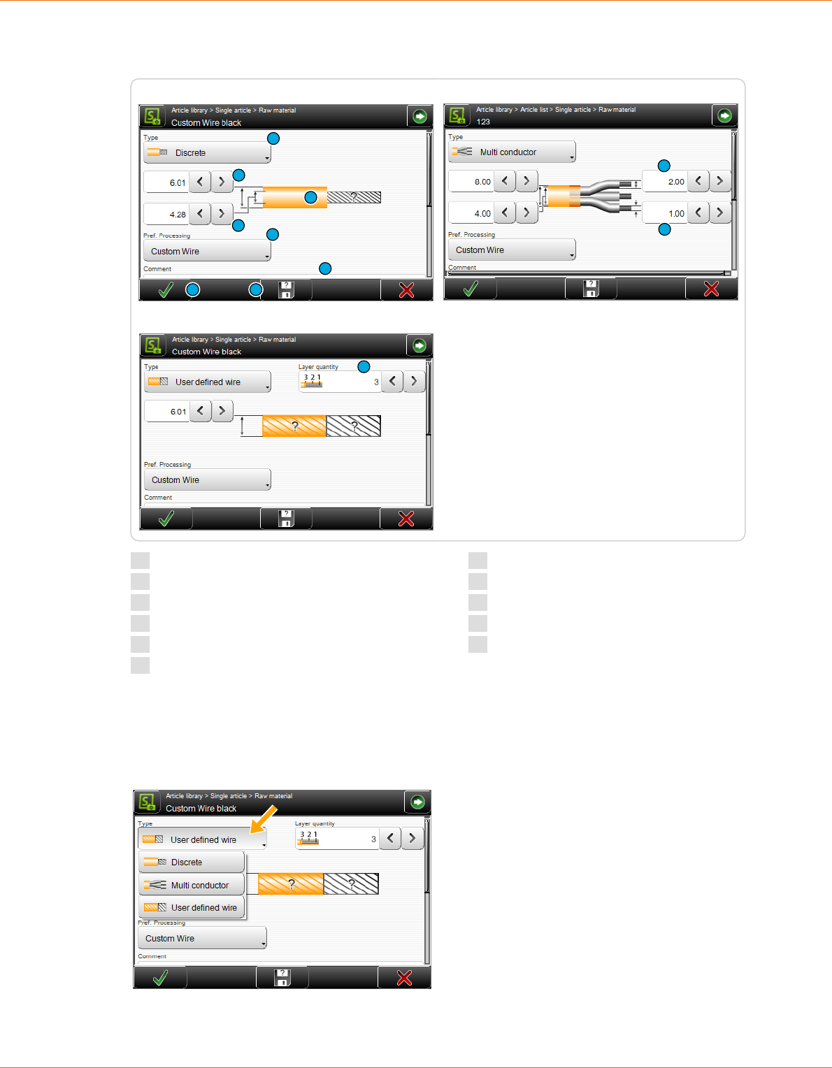
9. Library mode
100 | 214
Reference Manual | Edition 9.0 (03-2021) |
S.ON
Depending on the Raw material type, more or less selections are shown:
1
2
8
7
3
9
10 11
Single conductor:
4
5
Multi conductor:
6
User defined wire:
1
Type
2
Outer diameter jacket
3
Inner diameter
4
Outer diameter insulation
5
Outer diameter conductor
6
Layer quantity
7
Prefered processing
8
Pictogram of Raw material
9
Raw material comment
10
Saving Raw material
11
Saving Raw material under
Settings
Type
Denes the Raw material type to be produced.
Discrete: The outer- and inner diameter of a single wire can be entered separately.

9. Library mode
Reference Manual | Edition 9.0 (03-2021) |
S.ON
101 | 214
Multi conductor: As discrete but separate entry of the insulation diameter of a single wire and the
wire diameter itself.
User dened wire: Suitable for multi-layer coaxial cables and the slitting of wires. Here the outer
diameter and the amount of layers can be entered. The further diameters within the steps are dened
in the "Application editor".
Outer diameter jacket
Diameter of the outer insulation.
Inner diameter
Inner diameter of the jacket.
Outer diameter insulation
Diameter of the insulation of a single wire for multi conductor cables (e. g. Power cord).
Outer diameter conductor
Diameter of the inner wires of a single conductor on multi conductor cables.
Layer quantity
Denes the quantity of layers correlating with this Raw material. The entry eld is only visible if the
type "User dened wire" is selected.
Preferred Processing
Selection of the Processing from the Processing library which is linked to this Raw material. The selec-
ted Processing of the article can be overridden at any time under "Init".
Raw material comment
Here a comment, e. g. to conrm to change the Raw material, can be entered.
Saving Raw material
In the Library mode, the changed settings in the Raw material editor can be stored in the Raw materi-
al library with [OK].
Saving Raw material under
It is possible to modify existing or template Raw materials and then to save them under a dierent
name in the Raw material library.
The factory default Raw materials (templates) are write protected. Self -dened Raw materials can
therefore not be saved under these names.
For further information on the Raw material editor, also includes multi layers, see under „Standard
process ow“ "8.8 Raw material editor (Page 87)".
9.4.3
Raw material selection in the "Init" screen
In contrast to the standard process ow, Raw materials can be selected for the “Library mode” in the
"Init" screen from a drop-down list for linking.
Display and direct selection of a Raw material previously programmed and saved in the Raw material
library, and factory default Raw materials from the drop-down list.
1
2

9. Library mode
102 | 214
Reference Manual | Edition 9.0 (03-2021) |
S.ON
1
Self-created raw materials: Already programmed and in the Raw material library saved data.
2
Factory default Raw materials: Factory dened Raw materials, starting with „zz....“. Which Raw
materials displayed here depends on the machine type.
There are the following predened factory default Raw materials available.
zzz_Custom zzz_Default zz_Coax_4_Layers
zzz_PowerCord zz_Calibration
The factory default Raw materials are write protected. Self -dened Raw materials can therefore not
be saved under these names. But it is possible, to alter the pre-dened Raw material and then to save
it under a new name.
9.5
PROCESSING LIBRARY
The way in which the MultiStrip 9480 processes a certain article is saved in the Processing library as
le. This records describe how the MultiStrip 9480 processes a wire type (e. g. a Power cord or a Flat
ribbon). This is determined by data such as speed, incision depth, way back, air jet time, utilized
blades etc.
If a le in the library is changed, all articles linked to this le are changed instantaneously without any
extra action.
In the Processing library, alternatively to the le management, there is also the ability to change Pro-
cessing settings but independently from articles and article lists.
9.5.1
Processing library list view
For the description of the elements in the Processing list see "9.4.1 Raw material library, list view
(Page 98)".
9.5.2
Processing editor
An existing Processing can be edited. The Processing editor is opened.
The user can access the "Processing" screen via the [PROCESSING] key. Here the Processing settings
are dened.

9. Library mode
Reference Manual | Edition 9.0 (03-2021) |
S.ON
103 | 214
All for the user available Processings can be saved in the Processing library. This only is necessary
once for each Processing. The entered le then can be used in dierent articles and dierent article
lists as often as necessary.
1
2
1
Complete
2
Local
In the Processing editor, the settings can be changed in the dierent tabs.
In contrast to the "Standard process ow", there is in the "Library mode" in the "Elements" tab the key
[COMPLETE ELEMENTS]. Via this key, additionally required elements for the application of the current
article are automatically added.
If a library Processing is selected, the additional key [LOCAL] is displayed in the Processing editor.
Here in an easy way a local Processing can be produced from the write protected Processing library,
which can temporarily be used for the production. Then it can also be saved again under a new name
in the Processing library.
For the additional settings to the Processing editor, see "Standard process ow" "8.5 Processing editor
(Page 65)".
9.5.3
Processing selection in the "Init" screen
In contrast to the “Standard process ow”, Processing’s can be selected from a drop-down list to link
to.
Display and direct selection of Processing previously programmed and saved in the Processing library
from the drop-down list.

9. Library mode
104 | 214
Reference Manual | Edition 9.0 (03-2021) |
S.ON
1
2
1
Self-created Processing’s: Previously programmed and in the Processing library saved Proces-
sing’s.
2
Factory default Processing’s: Selection of the factory default Processing's Which factory default
Processing’s are shown here, depends on the selected wire processing machine.
When selecting a Raw material, its preferred Processing is selected automatically.
There are the following predened factory default Processing’s available.
zz_Coax_3_Layer_Succoform zz_Coax_4_Layer zz_PowerCord
zz_Zip_Cord zzz_Default
Plus additional product-specic default wire types often used.
The factory default Processing's are write protected. Self- dened Processing's can therefore not be
saved under these names. But it is possible, to alter the pre-dened Processing and then to save it
under a new name.
9.6
APPLICATIONS
9.6.1
Predened
See "Standard process ow", chapter "8.6 Application editor (Page 79)".
9.6.2
User dened
If the predened applications are not sucient "User dened application" can be used. With this pro-
gramming concept, all the options of the end Processing can be utilized.
The article can be programmed directly as “User dened application”. However, switching to "User-
dened application" after a predened application has been previously programmed, all settings of
the predened application are adopted.
The opposite direction from "User dened application" to the predened applications will not work.
Likewise, switching from predened applications to other predened applications deletes the previ-
ously entered data.

9. Library mode
Reference Manual | Edition 9.0 (03-2021) |
S.ON
105 | 214
The preset steps and settings calculated by S.ON can be viewed and edited in the article editor - appli-
cation screen. This is an additional programming aid for beginners, to gain a better understanding of
the step by step programming.
As soon as a “User dened application” is programmed, no schematically representation is shown
anymore in the editor “Processing Elements”.
Example of a multi-step stripping (the Raw material is produced here in multiple steps):
4.
3.
2.
Step 1.
Fig. 17: For example, pull-o in several steps
9.6.3
Layer sectioning on complex wires
Layer 1 in a complex cable such as multi-conductor, stands for the innermost layer, usually the con-
ductor of a cable. If no branches have been dened, the element applies for the whole layer. The type
of the operation mode for the layer is based on the nature of the raw material.
With the Schleuniger wire processing concept, layer sectioning always is dened from inside to out-
side.
1
2
1
2
3
Single wire
Multi conductor cable
Fig. 18: Layer sectioning
See also under "9.6.4.2 Branches (Page 107)".
9.6.4
Application editor
In the editor application, when "User dened application" is selected, so called operations, split in col-
umns, can be added or removed individually.
By touching the pictogram in the article editor (left or right end), the editor application is shown
where the operations can be programmed. First an overview of the operations is shown.

9. Library mode
106 | 214
Reference Manual | Edition 9.0 (03-2021) |
S.ON
4
3
2
1
Fig. 19: Application operations
1
Show next/previous column
2
Header line operation column
3
Operation settings
4
Operation-description
Show next / previous column
If there are several operation columns for a complex wire type, the user can jump to the next column.
Header line operation column
By touching the header line, the following drop-down list is displayed.
An additional operation column with all previous values is created. It
can then be edited.
The selected operation column is deleted.
Operation settings
The set value can be changed directly by pressing a value eld. Here the behavior of the
MultiStrip 9480 during the processing of the applications is dened.
Operation-description
Display of the operation description to the content.
Layer
The layer where the operation is to be per-
formed. Statement of the layer, 1 stands for
the innermost layer, usually the conductor of
a wire. If no branches have been dened, the
operation applies to the whole layer. The
type of the operation mode for the layer is
based on the nature of the raw material.
Layer 1 cannot be selected in stripping
mode, all existing layers would be stripped
this way, thus it would be a cut not a strip.
Only a valid layer according to the Raw
material setting can be selected here.
See also Chapter "9.6.3 Layer sectioning on
complex wires (Page 105)".

9. Library mode
Reference Manual | Edition 9.0 (03-2021) |
S.ON
107 | 214
Branches
In the editor Branch, the entered branches are
shown or changed. A block of several branch
ranges can be entered. This either is done by
touching directly the appropriate branch in a
selection of 12 branches, or in the lower area of
the screen as a text string. In the text string, the
sets are separated by a semi colon (e. g. 5;6;7)
One set can either be built from one branch or a
continuous range of branches (e. g. beginning
branch connected through a hyphen with an
end branch (e. g. 5-10). The text string also
allows denitions of branches exceeding a
range of 12.
The selection in the 12 branch keys is represented in the eld “Text string”.
Example 1: "5" is entered to separate a 10-core at cable between the fth and sixth branch.
Example 2: To shorten the branches 1 - 5 of the same at cable, the branches 1 to 5 are activated or
entered as text string "1-5".
If no branches are entered in the cell Branch, all branches are automatically selected in the modes
Strip, Comb, Separate and Shorten. In the mode "Slit", the central branch is selected in each case (in
the case of an even quantity of branches, the branch directly over the center).
Operation
Operation modes refer to dierent types of wire treatment that can be done by the MultiStrip 9480.
Stripping
Cutting the insulation over the whole circumference,
and then pulling-o the separated part from the rest
of the wire.
Comb
Combing several twisted conductors with the option-
al combing device.
Slit
Cutting the insulation lengthwise to the wire axis.
Requires a special slitting blade.
Separate
Separating the insulation lengthwise to the wire axis
on at cables, between the individual conductors. As
opposed to slitting, here the cut is not made on the
insulation of a conductor, but is centered exactly
between two adjacent conductors.
Shorten
This mode is used to shorten particular wires.

9. Library mode
108 | 214
Reference Manual | Edition 9.0 (03-2021) |
S.ON
Position
Denes the position for the operation element. It is dened within zero and the wire length.
Length
Denes the length of the treatment for this operation element.
Operation sequence
If "Operation sequence" is set to “Continuous”, the total treatment length of the linked operation is
determined by the length of the rearmost of this linked operation. The entry eld "Length" is disabled,
except with the last operation concerned.
Deactivated: With a full strip the article is produced as follows:
1
2 3
Fig. 20: Operation sequence = not continuous
Activated: Several operations are combined to one. All incisions and stripping are performed with
the same pair of blades, without opening the blades between the processing steps.
1
2 3
Fig. 21: Operation sequence = continuous
Direction
This denes the direction in which the e. g. slitting shall be performed.
The selections "To right end" or "To left end" are available.
Direction
To right end
Incising left (2)
Slitting wedge
Slit
Fig. 22: Direction
Right guide
Denes the behavior of the guide before the right feeding unit.
The following selections are available:

9. Library mode
Reference Manual | Edition 9.0 (03-2021) |
S.ON
109 | 214
Automatic
Retracted (the guide is moved out of the wire axes).
In wire axis
Pull-o with
Denes the method for the full strip on the right side, if it is dierent from the method in the Process-
ing. The standard behavior "Processing" can be prioritized here.
Available selections are:
Processing
Blade
Blades + feeding unit
Processing
Shows the Processing element of this operation. In the editor “Processing element”, additional ele-
ments can be added, deleted and settings within an element can be changed.
Additional settings for processing a layer are made here. This can be values like incising diameter, pos-
sible operating modes etc. The individual denitions per layer and branch, also per operating mode
are represented in detail in an element screen.
For additional information to the Processing element see Chapter "9.5.2 Processing editor (Page 102)".
Normal / autonomous
Denes how this operation shall be saved:
Normal: The operation will be produced with the appropriate element from the Processing. It is
treated the same way as on the rest of the article. When changing back, the message that the
autonomous Processing element is deleted, is shown.
Autonomous: A copy of the Processing element is stored in the operation.

9. Library mode
110 | 214
Reference Manual | Edition 9.0 (03-2021) |
S.ON

10. Article list mode
Reference Manual | Edition 9.0 (03-2021) |
S.ON
111 | 214
ARTICLE LIST MODE
In the main screen of the article list, single articles are added and settings necessary for the produc-
tion can be made. This screen is the central operating platform, where the user gains access in its user
level to all settings in the article list mode.
Article library
Article list
Article editor
Settings
Production
Start of machine
Fig. 23: Principle, "Article list mode"
In the "Article list mode" there is in comparison to the article library additional control elements.
1
6
5
4
7
8
9
10
2
3
1
List view
2
Produce article list
3
Article programming
4
Production settings
5
Production counter reset
6
Create new le
7
Options selected les
8
Select/deselect all les
9
Select actual le
10
Production release

10. Article list mode
112 | 214
Reference Manual | Edition 9.0 (03-2021) |
S.ON
10.1
LIST VIEW
The article list can be shown in dierent ways. This gives the ability to process the list sorted accord-
ing to dierent criteria. For a better overview, a simple view is shown by default.
The view can be changed by touching [LIST VIEW].
There are three dierent views:
Article list view 1:
Article list view 2:
Article list view 3:
View 1: In this list, the article name and the most important production settings from the article edi-
tor are shown.
TProd: Total articles produced in one list cycle
Cycle: Total processed list cycles
Quantity: Total quantity of articles to be produced
Prod: Total articles produced
Batch: Total batches to be produced
View 2: Here only the article name and the length are shown.
View 3: Here the article, -Raw Material-, and Processing names are shown.
10.2
ARTICLE LIST PRODUCTION
With [LOAD] or [CLOSE] and then [RUN], the articles can be produced directly from this list, in the
sequence from top to bottom. The production order can be changed by rearranging the article list
with [MOVE HIGHLIGHTED FILE UP/DOWN].
Production release: Only those article are produced for which the check box "Production release" is
activated and for which the production state is not yet at the end state.
With [SINGLE] or [CUT] only the actual selected article is produced.

10. Article list mode
Reference Manual | Edition 9.0 (03-2021) |
S.ON
113 | 214
If an article is opened in the editor, only this article is produced. But the list passes are added to the
counter.
10.3
ARTICLE PROGRAMMING
By touching the appropriate list row twice, the user is guided directly to the article editor, where as
usual all the settings of the selected raw material can be performed as in "Standard process ow" or
"Library mode".
10.4
PRODUCTION SETTINGS
Additional settings concerning the production process in "Wire list mode". In this screen the behavior
during the production e. g. quantity of passes, the order and the shown message before changing a
Raw material can be dened.
10.4.1
Production
Quantity
This value denes, how often the article list is to
be produced. We recommend e. g., to program
an article list which contains all the wires
required for a harness. The “List passes” eld is
then set according to the number of complete
harnesses to be produced.
Production sequence
Article lists can be produced in two dierent
ways.
"Article list rst" and "Single article rst" determine the way in which the article list is to be produced.
This dierence is only of signicance when the value for “List passes” is greater than 1.
Article list rst: The entire list is produced once, then this procedure is repeated by the quantity of
list passes. This way a list can be produced which corresponds e. g. to a set of wires for one harness.
An article list e. g with 5 dierent single articles was programmed and we wish to process this list 3
times. This means we have to switch to "Article list rst".
1
2
3
4
5
Single article rst: The MultiStrip 9480 produces the “Total” of each article fully (Quantity of “List
passes” x “Article quantity”), before proceeding to the next article. This mode is especially recommen-
ded when dierent Raw materials are used. Less waste is produced.
If the “Production sequence” is changed to "Single article rst", the list is produced as follows:

10. Article list mode
114 | 214
Reference Manual | Edition 9.0 (03-2021) |
S.ON
3 x 1
3 x 2
3 x 3
3 x 4
3 x 5
10.4.2
General
Raw Material change
Displays a message when the next article in the list needs a dierent Raw Material.
Comment
Displays a comment to it (instruction).
Processing change
Displays a message when the next article in the list needs a dierent Processing.
Comment
Displays a comment to it (instruction).
HotStamp setup
Displays a message when the next marking of the article needs a dierent text or an other text color.

10. Article list mode
Reference Manual | Edition 9.0 (03-2021) |
S.ON
115 | 214
10.4.3
Stop conditions
A ”Stop condition” describes an event during
the article list production, which stops the pro-
duction along with a subsequent action. The
kind of action is dened in the Wire list proper-
ties screen. There are several possibilities:
Do nothing, do not interrupt the production
at all.
Interrupt the production, display a mes-
sage.
Controlling a user dened device
Both (output a message and controlling a
user dened device)
The actions can be assigned to the correspond-
ing production step.
On a HotStamp setup, the last two options are
not available.
We must dierentiate between "Message" and
"User-dened device"
Message: Only the one with highest level is
output.
User dened device: Always trigger (even if several are present at the same time).
Single article complete
Denes a stop condition after the wire has been produced. The event occurs after each produced
wire. Since it is normally not recommended to interrupt the production after each wire, the default
setting is "Nothing".
Batch completed
Denes a stop condition after a batch has been produced. The event "Batch" occurs after each com-
pleted batch. This event is often used to control a device like a WireStacker3150 and to collect a batch
of articles. The default setting here is "Message".
Quantity complete
Denes a stop condition after the total quantity has been reached. This event occurs when all pieces
of a wire are produced. The default setting here is "Message".
Total quantity complete / Message (single article rst only)
Denes a stop condition after the total quantity has been reached. Occurs when an article has been
produced with all list passes. The default setting is "Message".
Article list complete / message (article list rst only)
Set a stop condition after the list has been produced. If the complete list is produced, this event
occurs. The default setting is "Message".
Total quantity complete / comment
If this setting is activated, the message entered in the text edit eld appears according to the behav-
ior dened under the production step.

10. Article list mode
116 | 214
Reference Manual | Edition 9.0 (03-2021) |
S.ON
Production complete / comment
Set a stop condition after the whole production has been accomplished. If the article list is produced
in the quantity of "List passes", the event "Production” occurs. The default setting is "Message".
Single article / comment
If this setting is activated, the message entered in the text edit eld appears according to the behav-
ior dened under the production step.
List / article comment
If this setting is activated, the message in the text edit eld appears as it was entered in the article
editor as “Single article” or “List comment”, according to the behavior dened under the production
step.
10.5
RESET PRODUCTION COUNTER
Resets the production counter for the list passes back to zero.
10.6
ADD NEW FILE / FILE FROM LIBRARY
Adds an article to the actual article list. Articles in "Standard process ow" or in "Library mode" can be
added. This way a whole daily production can be programmed and automatized. Independent copies
are produced this way. The production state in the original list persists. In the new list it can either be
taken over to or reset to zero.
Also existing articles from the article library can be added here.
10.7
OPTIONS SELECTED FILES
Additional commands for the manipulation of les in the article list like, duplicate, rename, delete and
repositioning les in the list.
10.8
PRODUCTION RELEASE
If the check box is set the article is produced on the next production start.

11. Production
Reference Manual | Edition 9.0 (03-2021) |
S.ON
117 | 214
PRODUCTION
11.1
LOAD RAW MATERIAL
11.1.1
Normal loading with [LOAD]
1.
▹
Insert the raw material into the
MultiStrip 9480 and feed up to the swivel
guide.
2.
▹
[LOAD]
11.1.2
Alternative loading with [CLOSE]
1.
▹
Feed the raw material passing the feeding
belts, into the MultiStrip 9480.
2.
▹
[CLOSE]
3.
▹
With [FEED], feed the wire beyond the
immovable or linear guide.
4.
▹
[CUT]
11.2
UNLOADING RAW MATERIAL
11.2.1
Normal unloading with [UNLOAD]
1.
▹
[UNLOAD]
➥ The raw material is fed backwards and
ejected on the left o the MultiStrip 9480,
then the feeding units open.
Caution: With certain pre-processing peripher-
al devices or units (e. g. wire straightener),
[UNLOAD] cannot be used as this would cause a jam. See next chapter.
11.2.2
Unloading with [OPEN]
1.
▹
[OPEN]
➥ Thereby only the feeding belts open and
the raw material can be removed by
hand out of the MultiStrip 9480.

11. Production
118 | 214
Reference Manual | Edition 9.0 (03-2021) |
S.ON
While using [UNLOAD] and [OPEN] the cutting unit opens (also the rotary incising unit) and feeding
belts to the in the Conguration dened maximum value.
2.
▹
Pull out the raw material on the left o the MultiStrip 9480.
11.3
RELOADING RAW MATERIAL
If the raw material has been used up during production, the lever of the wire end monitoring drops
down and the message "No raw material" is shown on the touch screen. The MultiStrip 9480 stops the
production immediately.
To load a new raw material after this, there are two possible ways:
11.3.1
Method A
1.
▹
Touch [FEED] until the last produced article
is ejected (check the last article for proper
production).
2.
▹
[OPEN]
➥ The lever of the wire end monitoring
goes up.
3.
▹
Feed the raw material passing the wire end monitoring and the monitoring guide up to the feed-
ing belts.
4.
▹
[CLOSE]
5.
▹
[FEED], and then [CUT]
➥ The feeding units close, the raw material
is fed beyond the blades and then cut
and ejected.
11.3.2
Method B
1.
▹
Touch [FEED] until the last produced article
is ejected (check the last article for proper
production).
2.
▹
[UNLOAD]
➥ The raw material is unloaded.
3.
▹
Feed the raw material passing the wire end
monitoring and the monitoring guide up to the feeding belts.
4.
▹
[LOAD]
➥ The feeding belts close until the raw
material is detected (they move to the
preset contact gap). Then the material is
fed and automatically cut. The slug is
ejected on the right.
1
2
1
2
3
2
1
3
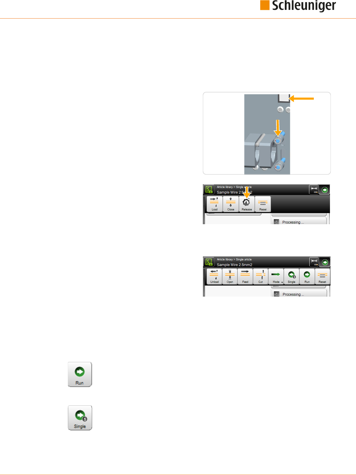
11. Production
Reference Manual | Edition 9.0 (03-2021) |
S.ON
119 | 214
11.4
OPERATION OF THE RECOIL BRAKE
The recoil brake is operated via the key on the machine front of the MultiStrip 9480 or on the touch
screen as follows.
11.4.1
Loading procedure
1.
▹
Put the machine into operational state for
raw material loading.
➥ The lever on the wire end monitoring is
up, the key [RECOIL BRAKE] on the
machine front is ashing and it is also dis-
played on the touch screen panel.
2.
▹
Insert the raw material and feed it up to the
feeding belts.
3.
▹
Press the [RECOIL BRAKE] key.
➥ The pulleys of the recoil brake close and
hold the raw material in position.
4.
▹
Touch [LOAD] or [CLOSE].
➥ The feeding belts close and position the
raw material, then the pulleys of the
recoil brake open.
11.4.2
Unloading procedure
1.
▹
Touch [UNLOAD] or [OPEN].
➥ The pulleys of the recoil brake close, the
recoil brake key is ashing and the key on
the touch screen is displayed again.
2.
▹
Hold the raw material on the entry with
your hand and press [RECOIL BRAKE].
3.
▹
Remove the raw material.
11.5
START PRODUCTION
11.5.1
Series production with [START]
The total quantity entered is produced at once. ("Quantity" + "Batch size"). During pro-
duction the "Production" screen is shown. See also Chapter "6 Installation / rst commis-
sioning (Page 27)".
11.5.2
Production with [SINGLE]
Only one single article is produced. This function is implemented normally to test the
settings. Here only the wire name is shown in the "Production" screen. At the end of the
production, automatically the article editor is shown again. The settings can now be
inspected and corrected if necessary. See also Chapter "6 Installation / rst commissioning
(Page 27)".

11. Production
120 | 214
Reference Manual | Edition 9.0 (03-2021) |
S.ON
11.5.3
Production in step by step- / speed control mode with [MODE]
With [SINGLE] as well as with [RUN] it can be observed during production whether all
steps have been processed correctly if the single step mode is switched on before pro-
duction.
Each movement step is accomplished with every keystroke. But synchronous move-
ments are still performed simultaneously.
1.
▹
The step by step mode can be switched on
before the production with [MODE].
Several settings are possible here:
Step by step
Speed control
Step by step combined with speed
control
2.
▹
[STEP BY STEP]
3.
▹
[SINGLE] or [RUN]
➥ The step by step information screen is
shown.
4.
▹
[STEP BY STEP]
➥ With each touch on [STEP BY STEP]
1
the
process cycle is advanced by one step.
5.
▹
[STEP BY STEP OFF]
2
terminates the step
by step mode. The production continuous
normally.
[CANCEL] terminates the production.
With “Speed control” the normal production state screen is shown, but the production performs slow-
er than normal. “Step by step” and “Speed control” can also be executed combined.
11.6
FURTHER COMMANDS / STATUS MESSAGES
11.6.1
Production screen
The production screen opens as soon as [SINGLE] or [RUN] was touched. With [SINGLE] only the arti-
cle name is shown and the user can switch to the step by step mode during production. For the nor-
mal production with [RUN] in addition to these, additional information important for the analysis is
shown.
1 2

11. Production
Reference Manual | Edition 9.0 (03-2021) |
S.ON
121 | 214
1
8
7
6
9
3
2
4
5
Fig. 24: Production screen, overview
1
Article name
2
Progress- article
3
Progress - batch
4
Progress - lists
5
Production break
6
Break interval
7
Speed control
8
Production step by step
9
Mode display
Production screen description
Article name
Show the currently loaded article in the machine buer.
Process article
Shows the overall production progress of single wires as quantity and percentage. In addition the
quantity of the already produced articles is shown.
Process batch
Shows the overall production progress of one batch as quantity and percentage. In addition the
quantity of the already produced batches is shown.
Process article list
Shows the overall production progress of one article list as quantity and percentage. In addition the
quantity of the already produced article lists is shown.
Break
The actual production is terminated. But the wire under production will be nished rst.
Break interval
The step by step break interval is set to zero in normal operating mode. To monitor the production
process, a pause between the individual processing steps can be set during production via the spin
box. A value between 0 and 10 seconds can be set.
Speed control
Via this spin box the processing speed can be decreased during the production. The speed can be set
in 10th steps.
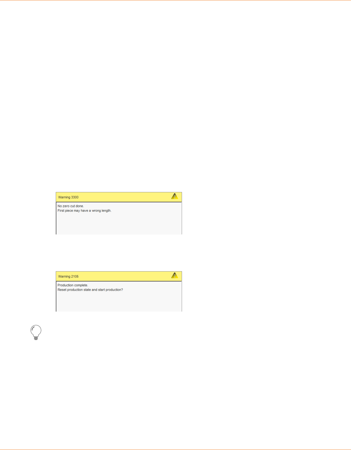
11. Production
122 | 214
Reference Manual | Edition 9.0 (03-2021) |
S.ON
In normal mode, the speed after the start is set to 100 % by default. This way the production is per-
forming with the pre-set values in the conguration. If the speed is decreased, the individual steps are
performing in lower speed.
If the mode "Speed control" is set, the speed is set to 0.
Production step by step
Here the user can switch to step by step mode during production.
Mode
Shows in which mode the production was started
11.6.2
Messages during start-up
Function not implemented yet.
11.6.3
Messages during the production
No zero cut done
If a raw material is loaded with [CLOSE] and then is not [CUT], or if between production cycles is fed
forwards with [FEED] and not [CUT] afterwards, a warning message is shown after starting the pro-
duction. After this message is shown, it is important to inspect the rst produced article for the prop-
er length.
Reset production
Another warning message appears if the same production is started twice. Here the production state
(counter) must be reset rst.
The production status is reset with [OK].
This message can be avoided, if reset is touched [PRODUCTION RESET] in the article editor before
restarting the production.
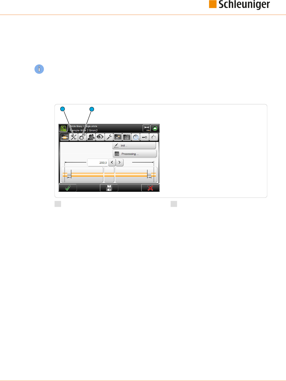
12. Conguration settings
Reference Manual | Edition 9.0 (03-2021) |
S.ON
123 | 214
CONFIGURATION SETTINGS
In the screens set up and conguration, the basic settings are carried out, which serve as a basis for
the functioning of the MultiStrip 9480. These settings are valid for all articles and aect the entire pro-
gramming on the machine.
The settings made here can be partially overwritten in individual screens in the Processing.
12.1
SETUP VERSUS CONFIGURATION
In accordance with the access authorization, the view "Setup" or "Conguration” is available.
1
2
1
Setup
2
Conguration
Setup
The function "Setup" is implemented for the daily use of the MultiStrip 9480 and it also helps the
beginner to get familiar quickly with the basic settings in the conguration. Here only the most
important settings can be changed (e. g. blade selection or switching on a PreFeeder, WireStacker,
CableCoiler or activating the "Short mode").
Conguration
In the Conguration" basically all settings for the MultiStrip 9480 and the behavior of the control soft-
ware can be altered. Hence the individual settings range is limited to the user level, the user is logged
in.
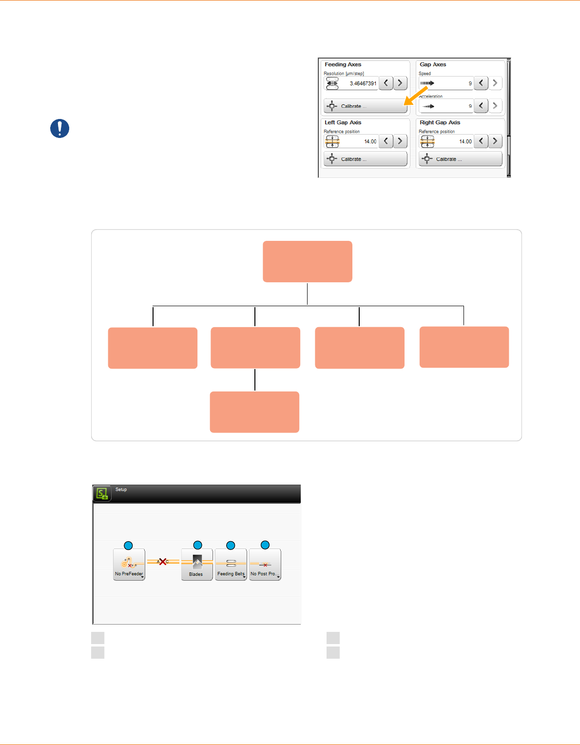
12. Conguration settings
124 | 214
Reference Manual | Edition 9.0 (03-2021) |
S.ON
12.2
CALIBRATE
In dierent screens of the setup and the cong-
uration, there is the key [CALIBRATION ...].
Through this a calibration of hardware compo-
nents can be carried out. Calibrations are in
most cases menu-guided via a wizard.
Caution: Calibrations are very delicate and
should only be carried out by qualied person-
nel (qualied personnel, technical specialist).
12.3
SETUP
Setup
PreFeeder
Blade cartridge
Library
Blade/tooling
Short mode
Post-processing
Depending on model
Fig. 25: Overview „Setup“
The main screen to setup the MultiStrip 9480:
1
2
3
4
1
PreFeeder
2
Blade- settings/-change/cartridges
3
Short mode / feeding type
4
Post processing device

12. Conguration settings
Reference Manual | Edition 9.0 (03-2021) |
S.ON
125 | 214
12.3.1
PreFeeder
Activate/deactivate an in the production line integrated pre feeder in the control software.
12.3.2
Blade settings- / change / cartridge selection
Selecting the blade cartridges (machines with cartridge system). Selection (activation) of the physical-
ly available blades and tooling on the MultiStrip 9480. Furthermore there is the command available to
move the cutting unit into the blade change position, to gain proper access to the blades.
12.3.3
Feed
Activate/deactivate a physically in the machine mounted "Short mode unit" in the control software.
12.3.4
Post processing device
Activate/deactivate an in the production line integrated wire stacker or cable coiler device in the con-
trol software.
Here also user dened devices can be selected that have previously been assigned in the congura-
tion (as long as they have been dened as post processing device).

12. Conguration settings
126 | 214
Reference Manual | Edition 9.0 (03-2021) |
S.ON
12.4
CONFIGURATION
Marking
Monitoring
Configuration
Machine
Production
Settings
Interfaces
Operating units
Cutting unit
Recoil brake
Wire end monitoring
Air jet unit
Length monitoring
Rotary incising unit
Feeding unit
User defined
Device
Jam detection
Post processing
Blade cartridge
Library
Blade/tooling
Clock Quality assurance
Fig. 26: Overview conguration

12. Conguration settings
Reference Manual | Edition 9.0 (03-2021) |
S.ON
127 | 214
The main screen in the conguration:
1 2 3 4 5
7
9 10 11 12
6 8
1
Marking
2
Machine
3
User-dened device
4
Monitoring
5
Post processing
6
Production settings
7
Clock
8
Quality assurance
9
Export conguration as screenshots
10
Conguration export as text le
11
Conguration data export
12
Conguration data import
12.4.1
Marking
Concerns about settings for the communication with Schleuniger marking devices.
1
2
1
HotStamp
2
Inkjet printer
HotStamp
Available: Deactivate to inhibit the connection
checking. The HotStamp device cannot be used
during production if it is not activated.
Distance: This denes the distance from the
HotStamp to the blade axis of the
MultiStrip 9480.
Calibrate...: The calibration of the distance is
menu guided.
Signal duration [ms]: During the signal dura-
tion the output to the HotStamp is activated,
the printing is started, respectively it takes as
long as the signal is on.

12. Conguration settings
128 | 214
Reference Manual | Edition 9.0 (03-2021) |
S.ON
Feedback: Deactivated = The signal is transferred according to the signal duration, after the waiting
time the MultiStrip 9480 continues with the production.
Activated = The signal is transferred according to the signal duration, after the device responds, the
MultiStrip 9480 continues with the production, as long as no "Time-out" occurs.
Timeout [ms] (feedback = on): Sets the time, how long the machine is waiting for a response from
the HotStamp device, until an error message occurs.
Pause after signal [ms] (when feedback = o) Time after the signal, in which the machine is waiting.
Inkjet printer
Type: Selection of the connected Inkjet printer.
In addition the interface is shown in brackets,
where the printer is hooked up to.
Time format: Country specic time format to
be shown. The list contains the standard combi-
nations for the 24- and the 12-hour system and
for the ISO and U.S. date format including the
display of the calendar week. For further infor-
mation see Appendix.
Date format: Country specic date format set-
ting. For further information see Appendix.
Distance: This denes the distance from the
print head to the blade axis of the MultiStrip 9480. If the printing head is placed right of the blades
(e. g. MegaStrip 9650), a negative value has to be set.
Calibrate...: The calibration of the distance is menu guided.
Print position tolerance: When this is set to "Small", the print procedure is slower, but the characters
to be printed on the article are positioned more exactly. The setting must be evaluated manually and
depends on the raw material diameter.
12.4.2
Machine
Here the general settings concerning the MultiStrip 9480 are made. Certain settings are password pro-
tected and are only visible if the user is logged-in to the appropriate user level.
1
2
3
4
8
9
5
6
7
10 11
1
Machine name
2
Recoil brake
3
Wire end monitoring
4
Air jet unit
5
Operating unit
6
Interfaces
7
Length monitoring
8
Rotary incising unit
9
Feeding units
10
Cutting unit
11
Jam detection

12. Conguration settings
Reference Manual | Edition 9.0 (03-2021) |
S.ON
129 | 214
Machine name
Denition of a machine name or a location description for this MultiStrip 9480. The name is also
shown in the header area of the touch screen
Recoil brake
Activate/deactivate the in the MultiStrip 9480 physically available recoil brake (option) in the control
software.
Wire end monitoring
Activate/deactivate the in the MultiStrip 9480 physically available wire end monitoring (option) in the
control software.
Air jet unit
Activate/deactivate the in the MultiStrip 9480 physically available air jet unit (option) in the control
software.
Operating unit
Pedal
Setup of the pedal behavior during the produc-
tion.
Available: Activate/deactivate a physically
available pedal connected to the MultiStrip 9480
(option) in the control software.
Interrupt: Activate/deactivate the production
interruption per pedal.
Message: Activate/deactivate the conrmation
messages per pedal
Start mode: Select the production start mode when using the pedal:
None: Start mode is deactivated
Single: Only one article (without aecting the production state)
Run: All articles
Run 1: Only one article
CAYMAN
Support: Here the CAYMAN support for controlling the MultiStrip 9480 via the wire processing soft-
ware CAYMAN is activated. An additional screen with the CAYMAN Symbol is displayed in the article
editor.
Ethernet port: Port number for the CAYMAN interface. These must be set the same as in the CAYMAN
software.
Interfaces
Here the ETHERNETinterfaces and signal I/O mappings are changed. Further software settings on the
interfaces must only be carried out by maintenance personnel of your Schleuniger distributor and
show up only after entering the appropriate password!

12. Conguration settings
130 | 214
Reference Manual | Edition 9.0 (03-2021) |
S.ON
1
2
1
Ethernet
2
Signal I/O mapping
ETHERNET
Connection of the MultiStrip 9480 to a TCP/IP
network (e. g. connection machine - PC, to oper-
ate together with the wire processing software
CAYMAN).
To establish a connection between PC and
machine, each device must be capable to send
data to the other. To make sure that this data
arrive correctly on the other station it must be
named (addressed) explicitly. For ETHERNET
networks this is done with an IP address.
DHCP automatic: Check with your IT administrator.
IP address: Available address in the local network (check with your IT administrator).
Subnet mask: Check with your IT administrator.
Standard gateway: Check with your IT administrator.
For additional information, see the CAYMAN - Reference Manual.
Signal I/O
The MultiStrip 9480 can be equipped with dierent interfaces which can be assigned user-dened. To
each signal used by the software (input/output) a pin can be assigned to. This allows a exible net-
working of devices with the automatic cut & strip machine.
Assignments can individually be exported/imported. To not assign each single pin to our standard
peripheral devices, we supply factory settings or packages from an USB data storage medium.
Signal I/O assignment: List entry of a signal I/O
assignment
1
.
Extended list commands: Export or delete
selected I/O assignment in the list
3
.
1
4
5
2
3

12. Conguration settings
Reference Manual | Edition 9.0 (03-2021) |
S.ON
131 | 214
Create new assignment: Creates a new list
entry of a signal I/O assignment
4
. A screen is
shown, where the signals can be assigned to the
built in hardware interfaces accessible on the
rear of the machine.
Assignment - device name: The name of the
device, freely selectable.
Assignment - activate: Activate the selected
signal (I/O).
Signal - name: Function of the signal on the
automatic cut- and strip machine, assigned
to the connector.
Hardware - connector: Applicable interface
type, assigned to the signal.
Hardware - Pin No: Applicable pin on the
interface, assigned to the signal.
Only the appropriate pins of the interface
are shown.
Hardware - Invert: Inverts the signal on the
assigned pin.
Hardware - lter duration [ms]: Sets the duration how long the signal shall be ltered (debounce
e. g. a relay).
Hardware - pin layout: Shows the connector type of the interface with the corresponding pin
assignment.
Hardware - Resolution [µm/step]: Denes the resolution of the encoder outputs. The value 100
µm/step is standard; 10 µm/step is recommended for inkjet printers.
For more information about the signal I/O assignment, are located in the supplementary instructions
manual "Schleuniger Machine Interface".
Import: Imports a standard package (factory
default settings) or a previously exported indi-
vidual assignment list from an USB data storage
medium
5
.
Load the factory default settings or the set-
tings on an USB data storage medium
6
.
Allow imports only from this machine or all
machines
7
.
Only exports or exports and backups are
allowed
8
.
Delete selected entries in the current
assignment list
9
.
6
7
8
9

12. Conguration settings
132 | 214
Reference Manual | Edition 9.0 (03-2021) |
S.ON
Length monitoring
The length monitoring (option) built into the
MultiStrip 9480 can be congured here. It monitors
every feeding to the right.
Length monitoring - available: Activate/deacti-
vate the length monitoring.
Tolerance - always allowed: Always accept up to
this tolerance. If the error is less than the tolerance,
no message is shown, otherwise a warning mes-
sage is displayed.
Tolerance - movement [%]: Range where no
action takes place through the length monitoring
(example: for a wire length of 100 mm, there is for
1 % tolerance an acceptable error of 1 mm).
Error message keys - ignore: If "Ignore" is activa-
ted, the additional key “Continue (F1)" is displayed
in the production screen. This decides whether the
error should be accepted.
Error message keys - correction: If "Correction" is
activated, the additional key “Correct (F2)" is dis-
played in the production screen. This decides
whether the error in the Processing should be automatically corrected.
Automatic correction - activate: The machine corrects a length deviation after a certain pause auto-
matically.
Automatic correction - pause: Waiting time until the automatic correction is performing.
Automatic correction - limit%: Trigger level from where the automatic correction is not performing
any more.
Automatic correction - trial quantity: How many times shall an automatic trial correction be per-
formed.
If length monitoring is activated, also the wire end monitoring function must be activated.
If the length monitoring is activated for a particular article in the Processing, but not in the congura-
tion, a warning message is issued.
Rotary incising unit
Cutting unit
Type: Displays the type of the rotary incising
unit.
Activate: Activates the rotary incising unit if it is
physically present.
Incising axis
Opening speed: Speed on which the blades
move in idle state. Here a value between 0 and 9
can be set.
Opening acceleration: Acceleration on which
the blades start up in idle state. Here a value
between 0 and 9 can be set.
Reference position: Sensor position for refer-
encing.
Reference position - calibrate ...: Start the gui-
ded calibration of the Reference position.

12. Conguration settings
Reference Manual | Edition 9.0 (03-2021) |
S.ON
133 | 214
Blade change
Sets the rotary incising unit into the blade
change position This way the spring force on
the blade holders is released and the blades or
cartridges can be safely changed.
Further software settings on the rotary incising unit must only be carried out by maintenance person-
nel of your Schleuniger distributor and show up only after entering the appropriate password!
Feeding unit
Feeding axes
Resolution: Denes the resolution of the feed-
ing units.
Calibrate: The calibration is guided by a wizard.
Clamping axes
Speed/acceleration: Speed and acceleration
with which the feeding units open/close. Here a
value between 0 and 9 can be set.
Left / right clamping axes
Reference position: Position of the feeding units (position of the sensor for the initialization).
Calibration: The calibration is guided by a wizard.
Tool change
The drives move to a position, where the feed-
ing belts/rollers can be replaced easily accessi-
ble.
Further software settings on the feeding units
must only be carried out by maintenance per-
sonnel of your Schleuniger distributor and show
up only after entering the appropriate password!

12. Conguration settings
134 | 214
Reference Manual | Edition 9.0 (03-2021) |
S.ON
Cutting unit
Type
Shows the type of the cutting unit.
Booster - available
Activates the cutting unit booster globally for all
Processing’s if this is physically present.
Blade cartridge library active
Activates access to the blade cartridge library,
where multiple cartridges can be stored and
one cartridge can be activated. If the setting is
deactivated, the table editor of the active cartridge can be accessed directly.
Blade changing axis (Y)
Speed: Denes the speed with which the blade-change axis moves.
Acceleration: Denes the acceleration with which the blade-change axis moves.
Cutting axis (Z)
Opening speed: Denes the speed with which the cutting axis moves.
Opening acceleration: Denes the acceleration with which the cutting axis moves.
Jam detection
Available: Activate/deactivate the in the
MultiStrip 9480 physically available jam detector
(option) in the control software.
Default key: Denes if the jam detection func-
tion in the editor "Processing - Options" shall be
switched on by default if [DEFAULT] is touched.
Distance: Denes the distance from the cutting
axis to the jam detector.
12.4.3
Cartridge selection / blade conguration / blade change
In this screen, the blades are allocated and calibrated in the software, according to the position in the
blade holder or on the cartridge.
Before the blades can be allocated, a blade cartridge must be created/allocated. This is done in the
cartridge library.
If the blade cartridge library is activated in "Conguration - Machine - Cutting unit", the blade car-
tridge library and the blade editor are displayed under "Setup - Blades".
If the blade cartridge library is switched o, only the blade editor is displayed under "Setup - Blades".

12. Conguration settings
Reference Manual | Edition 9.0 (03-2021) |
S.ON
135 | 214
1
2 3
1
Activate cartridge
2
New cartridge
3
Import cartridge data
Cartridge properties
Blade cartridge library: Activate/deactivate
the cartridge library in the control software.
Congure/activate blades
By touching the corresponding blade cartridge from the library or by selecting directly "Conguration
- Blades", the blade editor is opened. Here the blade type, the position and further settings for the
mounted blades are dened.
With S- and SR-models only one blade on position 1 is displayed and the settings for the blade width
and the blade position is invisible.
1
1
2 36 5
4
1
Blade number
2
Guided calibration
3
Distance
4
Blade change
5
Zero position
6
Blade type

12. Conguration settings
136 | 214
Reference Manual | Edition 9.0 (03-2021) |
S.ON
1
2
1
Option SmartDetect
2
SmartDetect channel
Blade no.
Denes the width and number of mounted blades. Normally the standard width 10.6 mm (3 blade
positions) or 16 mm (2 blade positions) is used. Alternatively the quantity of blades can be selected
from 1 to 10. The widths are freely denable then.
Guided calibration
The blade calibration is an automatic process and is only intended for standard- and customer specic
V-blades. This calibration must not be performed with radius V-blades. If inaccuracy occurs in the
range of such blades, the blade is either used up or defective. But it may also be, that the cutting unit
has small mechanical dierences. In this case a calibration has to be performed. In such a case contact
your local Schleuniger distributor.
Distance
Distance from the mechanical stop to the center of the blade.
Blade change
In the footer area, there is a [BLADE CHANGE] key which positions the cutting unit automatically on a
the blade change position. The user reconrms the mechanical blade change with [OK].
Z-zero position
This value is determined on the standard- and customer specic V-blades automatically via the cali-
bration function. For other blade types and tooling (combing device and other) it is xed dened by
the software.
Blade type
Denes the type of blades and the calibration values of the individual blades (depending on the
blade type). A choice must be made in each selectable position. If no blade is mounted, select “None”
The common blade types:
None: When no blade is mounted on the specic position.
V- blade, V-radius: For standard raw material with smaller cross section, cut and strip.
Radius: Firm, thin and extremely elastic and thick insulations.
Radius blade with centering: Prevents too deep an incision. Only suitable for stripping, not for
cutting through.
Die: Special blade, adapted to the conductor and the outer shape of a wire.
User dened: Special designs like slitting blades, at blades etc.
Slitting unit: Optional available slitting unit.
Spacer: By selecting special blade combinations it may occur that a space is left over between
blades and tooling. To make sure that the subsequent blade/tooling however can be positioned
exactly on the cartridge, a spacer (dummy blade) is needed, which lls the space on this position.

12. Conguration settings
Reference Manual | Edition 9.0 (03-2021) |
S.ON
137 | 214
Option SmartDetect
SmartDetect is an option for production monitoring. See chapter "7.11.1 “SmartDetect” (Page 49)".
SmartDetect channel
Allows to change the SmartDetect channel (none, 1 or 2).
12.4.4
User dened device
Customer specic pre-and post feed devices, or
devices not directly corresponding to the wire
processing (e. g. a warning light), can be activa-
ted here.
Device type: Selection of the device previously
dened under “Name".
Available: Activate, when the user specic
device is physically available.
Name: Free naming of the user dened device.
Distance: Distance between the cutting unit
and the user dened device.
Signal duration [ms]: Duration of the signal
sent to the user dened device.
Pause after signal [ms] (when feedback = o)
Time the machine will wait after the signal.
Timeout [ms] (feedback activated): Waiting
time until a feedback from the user dened device is sent.
Post processing activate: To use the user dened device as for post processing this option must be
activated.
Properties: If “post processing” is activated, additional settings can be made:
General - oset: Readjust the ejection position from the blades of the automatic cut- and strip
machine to the user dened device.
Blade
Ejecting position
Offset -
Offset +
Ejection - mode: Select ejection mode.
● Single: The produced article is ejected through the right feeding unit and not until then the
next article is being processed. Although this delays the production, the article is ejected in a
dened manner.
● Release: The nally processed article is fed to the ejecting position. Subsequently the right
feeding belts open to assure a dened handing over. This way the article is not ejected but
released.
12.4.5
Monitoring
Here the “SmartDetect” function is switched on. For the principle of operation, see chapter "7.11.1
“SmartDetect” (Page 49)".

12. Conguration settings
138 | 214
Reference Manual | Edition 9.0 (03-2021) |
S.ON
Available - Activate: Activate the “SmartDetect” function.
Error message key - Ignore: Must be activated to display the “Ignore” key in the error message when
“SmartDetect” reports a contact of the conductor. Production will continue and a bad part will be
accepted as good (ignoring the error message from “SmartDetect”).
12.4.6
Post-processing
This involves the general settings for the post processing devices like WireStackers or CableCoilers
connected to the MultiStrip 9480.
1 2
3
4
1
Without post processing
2
Passive wire stacker
3
WireStacker active
4
Cable coiler
Without post processing
Distance: Distance measured between the cut-
ting axis and the ejecting position.
Properties...: See Chapter "12.5 Extended set-
tings for peripheral devices (Page 141)".
Wire stacker (passive/active)
Available: The wire stacker can only be selected
in the list of active devices if activated here.
Distance: Measured between the cutting axis
and the ejecting position on the wire stacker.
Standard value = 138 mm, directly right of the
right feeding unit.
Properties...: See Chapter "12.5 Extended set-
tings for peripheral devices (Page 141)".

12. Conguration settings
Reference Manual | Edition 9.0 (03-2021) |
S.ON
139 | 214
Cable coiler
Available: The cable coiler can only be selected
in the list of active devices if activated here.
Distance: Distance measured between the
blade axis and the takeover position of the
CableCoiler. Standard value =138 mm, directly
right of the right feeding unit.
Properties...: See Chapter "12.5 Extended set-
tings for peripheral devices (Page 141)".
Functions - selected CableCoiler: Select a
standard CableCoiler.
If user dened CableCoiler is set here the func-
tions bellow can be dened manually:
Error monitoring: Activate for coilers which are able to detect errors during production.
Waste piece mode: Activate if the coiler has such a function.
Clamp: Activate if the coiler can clamp the article before starting the coiling process. If the function
clamping is activated, the parameter “Clamping oset ” is shown in the “Properties”.
Bind: Activate if the coiler can bind coiled articles. If the function bind is activated, the parameter
“Binding position” is shown in the “Properties”.
Eject: Activate if the coiler can control the ejection of the article.
On the CableCoiler 1450 there are the new functions waste piece mode, clamping, bind and eject.
12.4.7
Production settings
Production - prepare: If "Prepare" is activated,
the remaining article in the MultiStrip 9480 is
already pre processed during the production,
e. g. with Inkjet printer or HotStamp. This way
more articles can be produced with e. g. [SIN-
GLE], without constituting an new slug. If "Pro-
duction - Prepare" is deactivated, a pre-process-
ing on the successive article is not performed.
Activate "Production - Prepare" when pre-pro-
cessing operations are used. This way expensive
slug can be avoided.
Production - Hints: Activates/deactivates hints during the production. Also the „Short mode” mes-
sage is aected therewith.
Length precision - warning: Here the warning message is activated, which occurs, if the safety cover
was opened during a production pause. The length precision can be in such a case no longer be guar-
anteed, as with open safety cover the feed axes are not under power and the raw material can move
back and forth.
Parallel wire production: The MultiStrip 9480 can handle more than one raw material at the same
time. For this we need special guides which are in preparation in the Schleuniger factory.
Length precision - First pre-processing: Produces an antecedent slug before the rst pre-process-
ing. This ensures, that the article is positioned exactly on the blades before the pre-processing and
thereby the rst marking is positioned correctly.
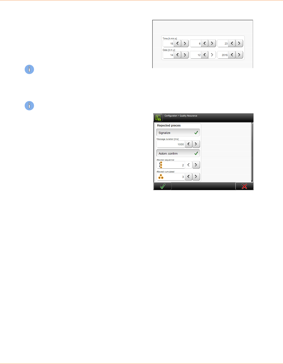
12. Conguration settings
140 | 214
Reference Manual | Edition 9.0 (03-2021) |
S.ON
12.4.8
Clock
Change of system time and date on the touch
screen.
In the entry elds of the spin boxes the current
time and date is shown. Here also the new val-
ues are set. To conrm the entry of the new val-
ues touch [OK].
The values must be set again, if the processor
PCB in the machine was replaces or the machine
was not in use for a long time.
12.4.9
Quality Assurance
The "Quality Assurance" key only appears if SmartDetect was previously activated in the "Monitoring"
menu with "Available".
Rejected pieces - Signalize: Activating enables
the setting of an output signal. However, the
eective signal setting is done in the Congura-
tion > Machine > Interfaces > Signal I/O map.
menu.
Message duration [ms]: Setting the message
duration in milliseconds (min. 0, max. 10000).
Conrm automatically: This switch opens two
further elds for setting options:
Allowed sequential Number of allowed con-
secutive touches during production.
Allowed cumulated: Total number of allowed
contacts during production.
As soon as one of the two counters is reached,
the error message is automatically accepted and the aected wire is automatically rejected.
12.4.10
Conguration export as screenshots
Create screenshots of the complete "Conguration" and the most important diagnostics screens.
Then store the screen shots on an USB memory stick plugged in.
12.4.11
Conguration export as text le
Create a text le of the complete "Conguration". Then store the text le on an USB memory stick
plugged in.

12. Conguration settings
Reference Manual | Edition 9.0 (03-2021) |
S.ON
141 | 214
12.4.12
Export conguration
Save the whole "Conguration" (actual settings)
on an USB memory stick connected to the USB
port.
12.4.13
Import the actual conguration data
Restore the whole "Conguration" (settings
from a previous conguration) from an USB
memory stick connected to the USB port, back
to the MultiStrip 9480.
This machine only: With the key in the upper
right corner we can dene, if only the congu-
ration data shall be displayed from this
MultiStrip 9480 or also conguration data from
another Schleuniger- machines.
Exports: The key in the upper right corner allows to choose whether to display only the exports
derived from this MultiStrip 9480 or exports and backups.
12.5
EXTENDED SETTINGS FOR PERIPHERAL DEVICES
12.5.1
Without post processing - properties
General
Oset: Therewith the ejecting position against
the blades (positive values) or away from the
blades (negative values) can be corrected. Neg-
ative values aect the article to be stick in the
feeding unit, and are only meaningful if "Kick
o" is switched on.
Eject speed: Here the produced article is ejec-
ted with the feeding speed dened under "Pro-
cessing - feed". Optionally a user dened combi-
nation of “Speed” and “Acceleration” can be set.
Eject
Mode: After the feeding units have stopped the article on the programmed position, it will be ejected
accurately.

12. Conguration settings
142 | 214
Reference Manual | Edition 9.0 (03-2021) |
S.ON
Continuous: The produced article remains in the right feeding belts and the next article is already
processing. Ejection takes place automatically at the next feeding. This setting does not delay the
production.
Single: The produced article is ejected through the right feeding unit and not until then the next
article is being processed. Although this delays the production, the article is ejected in a dened
manner.
Release: The nally processed article is fed to the ejecting position. Subsequently the right feed-
ing belts open to assure a dened handing over. This way the article is not ejected but released.
Kick-o: If the "Kick o" is switched o, the ejecting process has nished after approaching the ejec-
tion position. If “Kick-o” is switched on, the article is ejected as dened after reaching the ejection
position, e. g. a controlled feeding selected under "Kick o length" is carried out after.
Ejecting position
Kick-off
Fig. 27: Ejecting (kick-o)
12.5.2
WireStacker - properties
General
Oset: While ejecting the article, it is moved to
the position set in the screen "Conguration -
Wire stacker - Distance". This value denes the
distance from the wire stacker to the blades.
Normally the wire stacker is positioned directly
facing on the right feeding belts. With this value
the desired ejecting position against the blades
(positive values) or away from the blades (nega-
tive values) can be corrected. Negative values
aect the article to be stuck in the feeding unit,
and are only meaningful if "Kick o" is switched on.
Eject speed: With the setting "Feed speed" the article is ejected with the speed dened under "Pro-
cessing - feed". Optionally a user dened combination of “Speed” and “Acceleration” can be set for the
ejection.

12. Conguration settings
Reference Manual | Edition 9.0 (03-2021) |
S.ON
143 | 214
Distance to the wire stacker
WireStacker
- Offset +
Ejecting position
(distance from the blades)
Fig. 28: Ejecting with oset
Eject
Kick-o: If "Kick o" is deactivated, the ejecting process has nished after approaching the ejection
position (Wire stacker distance + ejection oset). If “Kick-o” is switched on, the article is ejected as
dened after reaching the ejection position, e. g. a controlled feeding selected under "Kick o" is car-
ried out after.
Distance to the wire stacker
WireStacker
Ejection position = distance wire stacker + offset
Kick-off
(distance from the blades)
Offset
Fig. 29: Ejection with „Kick o“ activated
Eject duration [ms]: Depending on the nature of the raw material, the eject operation requires more
or less time. This time is set in milliseconds [ms].
Wait after ejection [ms]: As soon as an article is ejected it takes some time until the wire stacker is
back in its reference position. The MultiStrip 9480 must therefore wait before it can feed the next arti-
cle (passive wire stacker only).

12. Conguration settings
144 | 214
Reference Manual | Edition 9.0 (03-2021) |
S.ON
Ejection (active WireStacker)
Batch tray: Denes how the batch tray should
move.
Batch - production stop: Denes the behavior
during a production stop.
12.5.3
Additional properties with active wire stacker
There are additional properties. This denes how the MultiStrip 9480 and the wire stacker shall act
after nishing a batch or the total production.
The options "Batch tray" and "Batch production stop" are available:
Batch tray
Function Batch complete Total complete
Swivel
Always bottom According to the list settings
or always with single articles
According to the list settings
or always with single articles
Always up According to the list settings
or always with single articles
According to the list settings
or always with single articles
Batch - production stop:
Function Batch complete Total complete
Never stop No message
Batch tray of stacker swivels
down
Message is shown
Batch tray of stacker swivels down
On each batch Message is shown
Batch tray of stacker swivels
down
Message is shown
Batch tray of stacker swivels down
On second batch 1. Batch:
No message
Batch tray of stacker swivels
down
2. Batch
Show message
Wait for [F1
Message is shown

12. Conguration settings
Reference Manual | Edition 9.0 (03-2021) |
S.ON
145 | 214
12.5.4
CableCoiler - properties
General
Oset: While ejecting the article, it is moved to
the position set in the screen "Conguration -
Wire stacker - Distance". This value denes the
distance in-between the blades and the Cable-
Coiler. With the "Oset" the desired ejection
position away from blades (positive values) or
against the blades (negative values) can be cor-
rected.
Eject speed: With the setting "Feed speed" the
article is ejected with the speed dened under
"Processing - feed". Optionally a user dened combination of “Speed” and “Acceleration” can be set for
the ejection.
Distance to the CableCoiler (distance from the blades)
Cable coiler
Offset
Fig. 30: Ejecting position cable coiler
Device specic
Here the user denes the position where the article has to be bind. Assuming the article will be bind
after half of it is coiled. In this case he enters 50 %. The coiler then stops on this position. The binding
position can be set to any position within the wire length. On 0 %, the function is disabled.
12.5.5
Programming
The post processing devices can be programmed on three dierent places:
Post processing mode
In the "Post processing" mode in the "Processing editor - Options" we dene if the post processing
device is controlled basically by the conguration or the Processing. The default value is set to "Con-
guration".
Programming in the Conguration
Work is carried out with the device selected in the "Setup" screen. If a Post Processing device is used
with any article, this can be selected in the screen "Conguration". This type of programming is ade-
quate if the machine is installed in a line with only one peripheral device and where the layout is
changed seldom or never. Each article is produced by using the peripheral device. Therefore the post
processing mode in the "Processing editor - options" must be set to "Conguration".
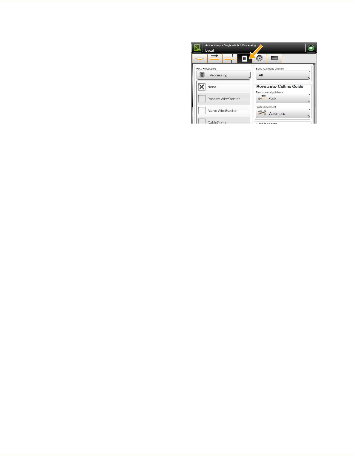
12. Conguration settings
146 | 214
Reference Manual | Edition 9.0 (03-2021) |
S.ON
In this case, the type of post processing device can be selected directly in the screen "Conguration".
The properties for the device can be selected within the corresponding sub menus.
Programming in the Processing
Production starts if the device selected in the
Basic conguration has been set in the Process-
ing.
Processing: If a designated article (dened by
the Processing) is used always with the same
post processing device, this can be selected in
the Processing. This type of programming is rec-
ommended if several peripheral devices are
available in a line. In this case, which peripheral
device is used during production, can be selec-
ted in the Processing of the article.
Local: If for a designated article a dened post processing device is used, it can be selected in the
local Processing. This type of Processing is recommended if a designated article has to be produced
dierently from the programmed single article in the list.

13. User interface / user levels
Reference Manual | Edition 9.0 (03-2021) |
S.ON
147 | 214
USER INTERFACE / USER LEVELS
In S.ON there are general settings which have to be altered rst before using it. See Chapter "6 Installa-
tion / rst commissioning (Page 27)".
To prevent the handling by unauthorized personnel, hence the access on certain user levels can be
restricted by a password.
13.1
SCREEN OVERVIEW
1 2
1
User interface
2
User levels
13.2
USER INTERFACE
The settings in the "User interface" screen apply to the general setup of the touch screen (system lan-
guage, measuring unit etc.).
User interface
Language: Select the desired language of the
touch screen surface. The available languages
are dependent on the installed language les.
Single mode - Single: The production counter
is not updated if producing with [SINGLE].
Single mode - Run 1: The production counter is
updated if producing with [START 1]. The pro-
duction key is displayed dierent.
Touch-keyboard - PC-Layout: Here the general keyboard layout can be determined. Selections are:
Standard keyboard (like PC keyboard) or alpha numeric (the keys are shown in alphabetic order).
PC layout: Alphanumeric layout:
Touch keyboard - tone: Activates/deactivates the touch tone. If the tone is switched on, an audible
sound is displayed after each touch of a key. This is an indication, that the key command has been
recognized.

13. User interface / user levels
148 | 214
Reference Manual | Edition 9.0 (03-2021) |
S.ON
Touch screen - calibrate: The calibration of the touch screen is necessary to bring the sensitive touch
surface in correlation with the pictures visually displayed. The operating matrix must correlate with
the virtually displayed keys and pictures.
A calibration is necessary in the following cases:
after replacing a component
after a data loss on the machine
with incorrect handling of the operation
with inaccurate sensitivity of the touch screen.
After touching CALIBRATION the calibration window shows up. In sequence touch the cross hairs dis-
played on the individual positions. Then terminate the calibration by touching the screen again.
Units
Length unit: Select the desired measuring unit. All length settings etc. are displayed in all screens in
the dened measuring unit. The measuring units "Millimeter (mm) or "Inch" are available.
Time/Date format: Switching between the common (country specic) Time- and Date formats. The
Time- and Date format is necessary for the display of the Time and the Date in the info area and for
the statistics in the production screen.
A detailed chart of the Time- and Date formats is available in the Appendix. See Chapter "17.2 Time /
date formats (Page 173)".
Screens
Here general settings concerning the display of
individual screens can be made.
New article: Denes, if the screen "New article"
shall be shown when creating a new article.
Default type: When creating a new article we
should be able to select by default between
"Single article" or "Article list". If the option "New
article" is deactivated, automatically the default
type "Single article" or "Article list" is preset.
Default mode: When creating a new article, we should be able by default to select between "Simple
mode" or "Library mode". If the option "New article" is deactivated, automatically the default type
"Standard process ow" or "Library mode" is preset.
Navigation bar: Activates/deactivates the automatic fade-out of the navigation bar.
Allow: Activates/deactivates the use of the library mode.
13.3
USER LEVEL
The settings in the "User levels" screen apply to the user level control of the S.ON software. It is possi-
ble to work in three dierent user levels.
The user logged in to a user level has only access to the commands and parameters designated for
this level. To e. g. change a conguration setting, the user must be logged in to the „Maintenance“ lev-
el.

13. User interface / user levels
Reference Manual | Edition 9.0 (03-2021) |
S.ON
149 | 214
User level
Available activated: The access to the control
software is restricted. Hence the user must log
in to the according user level before he can
execute the commands and change parameter
settings. The user status is displayed in the info
area.
Available deactivated: No user level log-in is
needed. After switching on the control soft-
ware, the user can access all screens and set-
tings unrestricted.
Actual user level: Shows in which user level the user is logged-in.
Password
User level setting: Selection of the user level in which the user has to be logged-in after restarting
the control software. The password can be changed individually on each user level. Initial factory
default passwords are programmed.
Touch Change password: The password can be changed individually for each user level. The new
password can be entered via the alphanumeric touch-keyboard (max. 14 characters). The password is
displayed encrypted.
Procedure for changing the password:
1.
▹
Select the desired [USER LEVEL].
2.
▹
[CHANGE PASSWORD]
3.
▹
Enter the old password on the alphanumeric touch-keyboard.
4.
▹
[OK]
5.
▹
Enter the new password.
6.
▹
[OK]
7.
▹
Conrm the new password.
8.
▹
2 x [OK]
Log-in defaults: The following keys are only visible in the user level "Operator" have only functionali-
ty there and may be set as follows:
Without
password
Password
Automatic
Login
Description
✕
The operator must always log in with the password.
✓ ✕
The password entry for the user level "Operator" is activated. But
the operator must still login on a software start up.
✓ ✓
The control software starts up automatically into the user level
"Operator" and without a password request.
Password reset: The factory default initial passwords remain in the memory even if they have been
renamed. While resetting the passwords to its initial settings all levels are aected. To carry out this,
the user must be logged in to the user level "Maintenance".
After a new MultiStrip 9480 has left the factory, the following passwords are predened (factory set-
ting):

13. User interface / user levels
150 | 214
Reference Manual | Edition 9.0 (03-2021) |
S.ON
User level Password
Operator 1
Programmer 12
Maintenance 123
Tab. 4: Preset passwords (factory default)
If the password for the user level "Maintenance" becomes lost, please contact your local Schleuniger
distributor.
13.4
USER LEVEL RESTRICTIONS
The following table shows, which functions can be accessed in which user level:
Screen
Operator
Programmer
Maintenance
Article
Create, save, temporarily changes ✕ ✓ ✓
Change, produce ✓ ✓ ✓
Login ✓ ✓ ✓
Setup (simple conguration)
Pre-processing (select a device) ✓ ✓ ✓
Marking (only display active devices) ✓ ✓ ✓
Blades (congure blades or select blade cartridge) ✓ ✓ ✓
Blade cartridge setup ✕ ✓ ✓
Post-processing (select a device) ✓ ✓ ✓
Conguration (extended) ✕ ✕ ✓
CAYMAN ✓ ✓ ✓
User ✕ ✕ ✓
Diagnostics ✕ ✕ ✓
Services
Data backup ✕ ✓ ✓
Data restore (Programmer: article data only) ✕ (✓) ✓
Logging ✕ ✕ ✓
Processing library ✕ ✓ ✓
Raw material library ✕ ✓ ✓
Tab. 5: User level restrictions

14. Diagnostics / troubleshooting
Reference Manual | Edition 9.0 (03-2021) |
S.ON
151 | 214
DIAGNOSTICS / TROUBLESHOOTING
S.ON is equipped with a comfortable diagnostics software, which is used to monitor the state of the
MultiStrip 9480 and the connected peripheral devices. Here the user can check the parts of the
machine and the peripheral devices in case of an error condition.
In the following screen the MultiStrip 9480 including pre-and post processing devices is graphically
represented. For the better overview, it is divided in several sub screens. All screens are described in
detail in the following section. At the moment only the screen "Machine" is available.
14.1
DIAGNOSTICS "MACHINE"
This checks the state of the MultiStrip 9480 and its internal and external interfaces.
1 2 3 4
5 6 7 8
9
Fig. 31: Overview, diagnostics machine
1
Assemblies
2
Electric platform
3
Interfaces
4
Operating unit
5
Peripheral interfaces
6
Operating status
7
Operating data
8
Hardware
9
Software
14.1.1
Components
The information of the components (titles) are taken directly from the hardware of the machine
(generic diagnostics). These are permanently stored in the rmware in "English". This enables the sim-
ple global localization of components for troubleshooting.

14. Diagnostics / troubleshooting
152 | 214
Reference Manual | Edition 9.0 (03-2021) |
S.ON
NOTICE
Uncontrolled motor movement
By moving the motor axes in the control software it may travel into the
mechanical stop. This can cause damage to the mechanics of the machine.
Move axes always under visual control.
In the diagnostics the user should avoid that the cutting unit booster hits the activated cutting bar.
This can be prevented as follows:
The motor of the cutting axis is de-energized before the booster is triggered.
The cutting axis is fully retracted before the booster is triggered.
If the cutting unit booster is triggered again and again to an activated cutting axis, the mechanism
can be damaged.
Function Description
Wire End Monitoring:
Concerns the wire end monitoring of the MultiStrip 9480.
Raw material detect
sensor
Display whether the sensor responds when a raw material was detected in
the wire axis.
Lift activation Move the lever of the wire end monitoring up (on/o).
Recoil Brake:
Concerns the recoil brake of the MultiStrip 9480.
Wire released sensor Indicate when the sensor of the recoil brake responds.
Button pressed sen-
sor
Display whether the button in the processing area was pressed.
Brake activation Invoke the pneumatic closing process of the recoil brake (on/o).
Light activation Activate/deactivate the lamp of the recoil brake switch located in the pro-
cessing area (on/o).
Length Monitoring:
Concerns the length monitoring of the MultiStrip 9480.
Encoder [Inc] Display the encoder position.
Close activation Activate squeezing of the pulleys (on/o).
Rotary Incising Unit:
Concerns the rotary incising unit of the MultiStrip 9480.
Centering axis - Axis
status
Displays whether the axis responds.
Centering axis - Axis
position
Display the axis position.
Centering axis - Initi-
alize
Perform an initialization (referencing) on the axis.
Centering axis - Move
to position
Move axis to a certain position.
Centering axis -
Motor
Switch on the motor of the axis.
Move the motor of the axis forward/backward (slow/fast).

14. Diagnostics / troubleshooting
Reference Manual | Edition 9.0 (03-2021) |
S.ON
153 | 214
Function Description
Incising axis - Axis sta-
tus
Displays whether the axis responds.
Incising axis - Axis
position
Display the axis position.
Incising axis - Refer-
ence sensor
Displays whether the reference sensor of the motor responds.
Incising axis - Encoder
[Inc]
Display the encoder position.
Incising axis - Initial-
ize
Perform an initialization (referencing) on the axis.
Incising axis - Move to
position
Move axis to a certain position.
Incising axis - Motor Switch on the motor of the axis.
Move the motor of the axis forward/backward (slow/fast).
Rotating axis - Axis
status
Displays whether the axis responds.
Rotating axis - Motor
rotating
Rotate axis (on/o).
Rotating axis - Motor
direction
Set axis direction (CW/CCW)
Rotating axis - Motor Activate motor (on/o).
Move the motor of the axis forward/backward (slow/fast).
Feeding Unit Left:
Concerns the left feeding unit of the MultiStrip 9480.
Clamping axis - Axis
status
Display whether the axis responds.
Clampingaxis - Axis
position
Display the axis position.
Clamping axis - Initi-
alize
Perform an initialization (referencing) on the axis.
Clamping axis - Move
to position
Move axis to a certain position.
Clamping axis - Refer-
ence sensor
Display whether the reference sensor of the motor responds.
Clamping axis - Con-
tact sensor
Display whether the contact sensor of the motor responds.
Clamping axis - Motor Switch on the motor of the axis.
Move the motor of the axis forward/backward (slow/fast).
Feeding axis - Axis
status
Display whether the axis responds.
Feeding axis - Axis
distance
Display the axis distance.

14. Diagnostics / troubleshooting
154 | 214
Reference Manual | Edition 9.0 (03-2021) |
S.ON
Function Description
Feeding axis - Initial-
ize
Perform an initialization (referencing) on the axis.
Feeding axis - Move
distance
Move the axis a certain distance.
Feeding axis - Motor Switch on the motor of the axis.
Move the motor of the axis forward/backward (slow/fast).
Cutting Guide:
Concerns the cutting guide (left swivel guide before the blades) of the MultiStrip 9480.
In wire axis sensor Displays whether the sensor responds, if the cutting guide is within the wire
axis.
Initialize Perform an initialization (referencing) on the cutting guide.
Motor Switch on the motor of the cutting guide.
Move the motor of the cutting guide forward/backward (slow/fast).
Cutting Unit:
Concerns the cutting unit of the MultiStrip 9480.
Blade changing axis -
Axis status
Displays whether the axis responds.
Blade changing axis -
Axis position
Display the axis position.
Blade changing axis -
Reference sensor
Displays whether the reference sensor of the motor responds.
Blade changing axis -
Initialize
Perform an initialization (referencing) on the axis.
Blade changing axis -
Move to position
Move axis to a certain position.
Blade changing axis -
Motor
Switch on the motor of the axis.
Move the motor of the axis forward/backward (slow/fast).
Cutting axis - Axis sta-
tus
Displays whether the axis responds.
Cutting axis - Axis
position
Display the axis position.
Cutting axis - Refer-
ence sensor
Displays whether the reference sensor of the motor responds.
Cutting axis - Encoder
[Inc]
Display the encoder position.
Cutting axis - Initialize Perform an initialization (referencing) on the axis.
Cutting axis - Move to
position
Move axis to a certain position.
Cutting axis - Motor Switch on the motor of the axis.
Move the motor of the axis forward/backward (slow/fast).
Booster - Out of wire
axis sensor
Displays whether the sensor responds, if the cutting unit booster is out of
the wire axis.

14. Diagnostics / troubleshooting
Reference Manual | Edition 9.0 (03-2021) |
S.ON
155 | 214
Function Description
Booster - In wire axis
sensor
Displays whether the sensor responds, if the cutting unit booster is within
the wire axis.
Booster - Activation Activate the cutting unit booster (on/o).
Air jet - Air activation Activate the air jet unit (on/o).
Wire End Monitoring:
Concerns the monitoring with SmartDetect unit of the MultiStrip 9480.
Touched state Display whether there is contact between the blade and the conductor.
Monitoring On/O Monitoring on/o
Feeding Guide Right:
Concerns the rights feeding guide (right of the blades) of the MultiStrip 9480.
Out of wire axis sen-
sor
Displays whether the sensor responds, if the right cutting guide is out of the
wire axis.
In wire axis sensor Displays whether the sensor responds, if the right cutting guide is within the
wire axis.
Initialize Perform an initialization process (referencing) of the feeding guide (Caution:
"Initialize" only works if the "Short mode" unit is not installed).
Motor Switch on the motor of the cutting guide.
Move the motor of the cutting guide forward/backward (slow/fast).
Feeding Unit Right:
Concerns the right feeding unit of the MultiStrip 9480.
Clamping axis - Axis
status
Display whether the axis responds.
Clamping axis - Axis
position
Display the axis position.
Clamping axis - Initi-
alize
Perform an initialization (referencing) on the axis.
Clamping axis - Move
to position
Move axis to a certain position.
Clamping axis - Refer-
ence sensor
Display whether the reference sensor of the motor responds.
Clamping axis - Motor Switch on the motor of the axis.
Move the motor of the axis forward/backward (slow/fast).
Feeding axis - Axis
status
Display whether the axis responds.
Feeding axis - Axis
distance
Display the axis distance.
Feeding axis - Initial-
ize
Perform an initialization (referencing) on the axis.
Feeding axis - Move
distance
Move axis to a certain position.
Feeding axis - Motor Switch on the motor of the axis.
Move the motor of the axis forward/backward (slow/fast).

14. Diagnostics / troubleshooting
156 | 214
Reference Manual | Edition 9.0 (03-2021) |
S.ON
Function Description
Jam Detector:
Concerns the jam detector at the output of the MultiStrip 9480.
Raw material detec-
ted
Indicate when a produced article is detected on the outlet.
14.1.2
Electric platform
The information of the components (titles) are taken directly from the hardware of the machine
(generic diagnostics). These are permanently stored in the rmware in "English". This enables the sim-
ple global localization of components for troubleshooting.
Function Description
Safety state Display whether the safety state is enabled.
Opened safety circuit Display whether the safety circuit on the main control PCB detects "Opened".
Fan activation Activate the fans in the electronic compartment (on/o).
Light activation Activate the light in the drive compartment (on/o).
Fan activation Activate the fans in the drive compartment (on/o).
Power activation Activate the power supply for the electronics control (on/o).
14.1.3
Interfaces
Test for the in- and outputs of the electronics and the external interfaces of the MultiStrip 9480.
ETHERNET connection
Display of the ETHERNET port addresses and further information.
14.1.4
Operating unit
Currently no information available under this category.
14.1.5
Peripheral interfaces
The information of the components (titles) are taken directly from the hardware of the machine
(generic diagnostics). These are permanently stored in the rmware in "English". This enables the sim-
ple global localization of components for troubleshooting.
Function Description
Prod run feed
involved2
Display the machine status with attached peripheral devices.
Prod run feed
involved1
Display the machine status with attached peripheral devices.
Depending on the conguration more setting options appear.
This includes:
Marking devices (HotStamp, ink jet printers)
User dened devices
Post-processing devices (WireStacker, CableCoiler)

14. Diagnostics / troubleshooting
Reference Manual | Edition 9.0 (03-2021) |
S.ON
157 | 214
14.1.6
Operating status
The operating status provides information about the currently available memory space for articles
and other libraries.
The information in this screen are mainly dependent on the MultiStrip 9480 conguration.
CPU memory: Display of remaining memory available for articles and other libraries.
Real-time: Displays whether the internal clock has been reset.
Machine: Identication number of the MultiStrip 9480.
14.1.7
Operating data
The operating data are available for machine and operating unit. Here common production data like
total quantity of all produced wires on this machine, production times etc. are displayed.
The information refers in general to the total run time since the machine for the rst time has been
put into operation.
Machine / operating unit
Switched on: How often was the machine switched on and how long was it turned on.
Emergency stop: How often was the emergency stop button activated.
Axes, rotation and other units: Display of the duration of operation and/or the display of the
operating counters (axis movements).
Production
Total counter: Counts all articles ever produced on this machine.
Production time: Includes everything from pressing the "Start" button until the production dia-
log has been closed.
Production eective time: Excludes the time when a message was output (production interrup-
ted).
The production via CAYMAN is included in the production time.
Software
Fatal error: The number of serious errors encountered in the software.
Not enough RAM: How often was the memory completely lled.
Communication
CAYMAN connected: How long was the machine connected to CAYMAN.
Connection lost: How often has the machine lost the connection to CAYMAN.
LabView test
The test was successful or failed.
Hardware
Counters of the individual states in the control electronics.
14.1.8
Hardware
Here versions of the individual hardware components are displayed. These must be communicated in
a support request to the service department of the local Schleuniger distributor.

14. Diagnostics / troubleshooting
158 | 214
Reference Manual | Edition 9.0 (03-2021) |
S.ON
14.1.9
Software
Here versions of machine and operating unit software are displayed. These must be communicated in
a support request to the service department of the local Schleuniger distributor.
14.2
MESSAGES
On the touch screen, status messages are displayed which may show up before, during and after the
production.
There are three types of messages which could occur during the production or programming the
MultiStrip 9480:
General information
Warning
Error
General Information is self-explanatory in most cases and not specically listed here. The most impor-
tant warnings and errors concerning the production are shown in the following chart:
For further messages, see the PDF-document „S.ON Messages“ where all in S.ON available hints, warn-
ings and error messages are listed in detail.
14.2.1
Warning
Instruction Description / action
2500: Protected mode
active! Axis may be moved
unlimited.
Caution: Look out, mechanical stop may be hit! The machine may be
damaged in this mode if handled improperly.
3300: No zero cut done.
First piece may have a
wrong length.
See Chapter "11.6.3 Messages during the production (Page 122)".
3302: PreFeeder fault. The PreFeeder has not been connected properly. Check the cable con-
nection to the PreFeeder device! PreFeeder is possibly defective.
3303: No pedal detected. Pedal not connected properly or defective.
3304: No CableCoiler detec-
ted.
The CableCoiler has not been connected properly. Check the cable
connection to the CableCoiler device! CableCoiler is possibly defec-
tive.
18003: Checksum error
in .....le.
File defective. Delete le and enter le data again.
18010: Store current wire
data in le?
The settings made in the wire screen are not saved yet and can be
saved now.
18011: Continue anyway? The changed Raw Material or Processing data have not been saved
yet and will be discarded if continuing.
18014: Really set default
values?
Default values will be set. Previously made settings can be lost.
18015: Reset production
state?
The programmed amount of articles has been produced, the produc-
tion state must be reset before the production can be continued.
18017 Local processing of
the article will be deleted.
While selecting a Processing from the library, all previously made local
Processing settings will be lost.
18023 Update in Processing
library?
Caution: All article les linked to this Processing will also be changed.

14. Diagnostics / troubleshooting
Reference Manual | Edition 9.0 (03-2021) |
S.ON
159 | 214
Instruction Description / action
18030: USB memory stick
not found.
Insert stick (it may take up to 1 minute after inserting the stick until it
is found by the machine). Only the stick supplied by Schleuniger shall
be used.
18042: Update in Raw
material library?
Caution: All article les linked to this Raw material are dependent on.
18094: Change processing
default values?
When changing raw material, it is recommended to calculate the
default values. [OK]: Really calculate processing default values adap-
tively (recalculates raw material diameter depending values only and
takes previous changes to those values into account)? [ALL]: Calculate
processing default values for entire processing (existing autonomous
processing elements are deleted). [NONE]: Do not change any pro-
cessing value.
Tab. 6: Diagnostic warning messages
14.2.2
Error
Instruction Description / action
5303 Wire end monitoring
detects no raw material.
No raw material loaded / wire end switch on wrong position / raw
material used up during production.
5308 / 5316: Cut axis was
blocked.
Too thick raw material loaded / cut axis feed speed too high / blades
mounted improperly.
5321: Error on fan electron-
ics.
Fan blocked / ventilator lter dirty. Fan defective, replace fan.
5332 / 5333: Check spacing
between the texts.
Areas programmed to close successive! Feed speed set too fast for the
communication with the printer.
5336: Machine is overhea-
ted!
Check ventilator lter. Possibly fan defective / fan exhaust blocked /
ambient temperature too high.
20004: Unknown data for-
mat.
Any open le is not usable, carry out another software update, use lat-
est version!
20005: File is incompatible
to the current software ver-
sion.
Carry out the machine software update again. Use the latest version!
20067: Loading language. Carry out the machine software update again.
20111: Backup failed. USB memory stick full, not formatted or defective.
20112: Data restore failed. Data on the USB memory stick not valid or stick defective.
Machine- and panel soft-
ware versions incompatible.
Check the software version in the diagnostic.
Tab. 7: Diagnostic error messages
14.2.3
Error message protocols
On an error state (e. g. hardware incompatibility) an additional button
1
is shown in the error mes-
sage dialog. The following information is displayed by repeated actuation:
General fault description

14. Diagnostics / troubleshooting
160 | 214
Reference Manual | Edition 9.0 (03-2021) |
S.ON
Machine Control Application Log (protocol les of the machine control)
User Interface Application Log (protocol les of the user interface)
2
1
With the “Data Backup” button
2
all log les stored on the machine can be saved to a USB data stor-
age medium. These logs are for the Schleuniger support and serve for the exact analysis of hardware
problems.
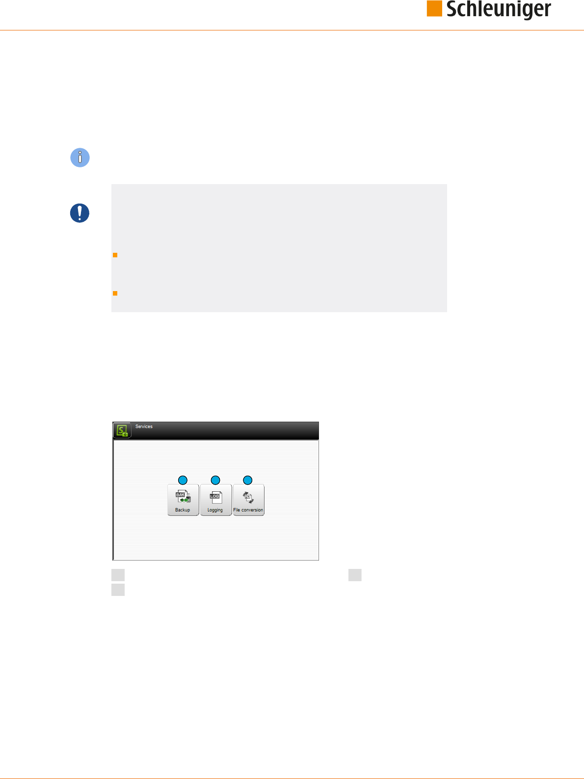
15. Data management / upgrades / services
Reference Manual | Edition 9.0 (03-2021) |
S.ON
161 | 214
DATA MANAGEMENT / UPGRADES / SERVICES
This chapter contains information for the backup and restore of data and the software upgrade. Addi-
tionally we can change settings concerning the protocol reporting during the production.
Personnel qualication
The instructions in this chapter must be carried out by qualied personnel!
NOTICE
Data loss USB data storage medium!
Inadequate handling or using a wrong USB data storage medium can lead to
data loss.
For the data backup compulsory use the USB data storage medium deliv-
ered with this software, as not all USB types are recognized by the soft-
ware, see document "Parts Catalog”.
The USB data storage medium must be formatted with the Microsoft le
system ”FAT”.
15.1
SERVICES
15.1.1
Main screen
For a clearly arranged overview, the "Services" screen is divided into several sub-screens. They will be
described here in detail.
1 2 3
1
Data backup
2
Logging
3
File conversion

15. Data management / upgrades / services
162 | 214
Reference Manual | Edition 9.0 (03-2021) |
S.ON
15.1.2
Backup
Here article data and the conguration of the MultiStrip 9480 is saved on an USB memory stick to
restore after a data crash or for other use.
1
2
1
Backup
2
Redo
Backup
All article- and the conguration settings are
saved to an USB memory stick through this
function.
File name (save as...): A le name
1
, composed
of Date, Time and the machine name/location is
proposed. But also a dierent le name can be
entered here. Then the data backup is started
with [OK].
Name: Previously created backups from a par-
ticular machine are displayed in the list.
Delete: Via the key [DELETE]
2
, the highlighted
backup data in the list are removed from the
USB memory stick.
After a successful data backup, a message shows up which can be conrmed with [OK].
Redo
All article data and conguration settings of this
or any other wire processing machine can be
restored from an USB memory stick via this
function.
Name: Previously created backups from this
machine or any other are displayed in the list
are shown here.
This machine only: Via the key [THIS MACHINE
ONLY]
1
the data are identied unique and only
the data of the actual machine is shown. After
selecting the corresponding le from the list
and then conrming with [OK], the data are
restored.
Delete: Via the key [DELETE]
2
, the selected backup data in the list are removed from the USB memo-
ry stick.
After a successful data restore, a message shows up which can be conrmed with [OK].
1
2
2
1

15. Data management / upgrades / services
Reference Manual | Edition 9.0 (03-2021) |
S.ON
163 | 214
15.1.3
Logging
The production procedures on the machine can be written into a protocol le for statistical use and
for the trouble shooting. In this screen the protocol data can be managed and the software can be set
up in a way that the logging is activated.
The protocols can be directly viewed, printed-out or exported to an USB-Memory stick for further
analysis on a PC.
2
1
3
1
Logging settings machine
2
Protocol settings user interface
3
Export log le
Logging settings machine: Here the user denes how and which data of the MultiStrip 9480 shall be
saved to the log le.
The following levels of the logging are available:
None
Error
Warning
Information
Debug
Protocol settings user interface: Here the user denes how and which data of the user interface
shall be saved to the log le.
The following levels of the logging are available:
None
Error
Warning
Information
Debug
Export logging le: Here the produced actual log le can be stored on an USB memory stick.
After a successful export, a message shows up which can be conrmed with [OK].
15.1.4
File conversion
To improve performance, old les (article, raw material and processing) are converted to the current
data version. 1 time per machine start the user is informed if his data is still stored in an older version.

15. Data management / upgrades / services
164 | 214
Reference Manual | Edition 9.0 (03-2021) |
S.ON
1
1
Convert all les
After touching [CONVERT ALL FILES] a warning appears that all les, including les with write protec-
tion, will be converted to the latest data format. This means that the les are then no longer compati-
ble with older S.ON versions.
After conrming the question whether to continue with the conversion, the conversion starts.
After successful conversion, return to the "Service" menu by pressing the bottom left key.
15.1.5
Software upgrade
To keep the operating software S.ON, possibly the rmware and the operating system up to date, a
software upgrade can be performed.
Preparing the data
To be able to carry out an upgrade, the upgrade data must be available on an USB data storage medi-
um. The data storage medium for the upgrade then is connected to the USB connection of the auto-
matic cut & strip machine.
To make the data on the USB data storage medium available, a special installation program is availa-
ble which can be downloaded from the Internet or delivered by the Schleuniger distributor, see next
chapter. For the upgrade procedure, an external Windows-PC is needed.
NOTICE
Caution, data loss!
If an error occurs during the software upgrade, data loss can occur.
Normally no article data are lost during an upgrade. Hence before a software
upgrade we recommend to save all wire data via the export function in the
"Service" screen, to an USB memory stick.

15. Data management / upgrades / services
Reference Manual | Edition 9.0 (03-2021) |
S.ON
165 | 214
Upgrade procedure
1.
▹
Install the USB data storage medium
upgrade tool on the PC (le „MachineUpda-
teTools_Installer.exe“).
2.
▹
[NEXT]
3.
▹
Select the path where the software on the
PC shall be installed (use the default path or
enter a new one via [BROWSE]).
4.
▹
[INSTALL]
➥ The installation starts.
5.
▹
Select the option as in the gure.
6.
▹
[FINISH]
7.
▹
Choose the language.
8.
▹
[OK]

15. Data management / upgrades / services
166 | 214
Reference Manual | Edition 9.0 (03-2021) |
S.ON
9.
▹
Connect a new USB data storage medium
to the PC, which is formatted with the
Microsoft le system "FAT".
10.
▹
[NEXT]
11.
▹
[NEXT]
12.
▹
Select the path where the USB data storage
medium was recognized by the PC (e. g. D:\
or E:\).
13.
▹
[INSTALL]
14.
▹
A message appears stating that existing
les on the USB data storage medium will
be deleted and that the deletion may take
some time.
15.
▹
[OK]

15. Data management / upgrades / services
Reference Manual | Edition 9.0 (03-2021) |
S.ON
167 | 214
16.
▹
Operating system, rmware data and S.ON
are copied to the USB data storage medi-
um.
17.
▹
Insert the prepared USB data storage medi-
um in the USB connection of the machine.
➥ The upgrade starts automatically. A mes-
sage shows up, that the upgrade is per-
forming. After a successful upgrade, an
appropriate message is displayed.
18.
▹
[NEXT]
19.
▹
[CLOSE]
➥ The upgrade procedure is terminated.

15. Data management / upgrades / services
168 | 214
Reference Manual | Edition 9.0 (03-2021) |
S.ON

16. Programming tips / examples
Reference Manual | Edition 9.0 (03-2021) |
S.ON
169 | 214
PROGRAMMING TIPS / EXAMPLES
For programming examples to our Schleuniger products, we refer to the add-on document „Program-
ming examples for wire processing“. There you will nd dierent examples from the eld, which can be
worked through step by step, and give the user an in-depth understanding in handling the wire pro-
cessing software S.ON.
See Table of contents.

16. Programming tips / examples
170 | 214
Reference Manual | Edition 9.0 (03-2021) |
S.ON

17. Appendix
Reference Manual | Edition 9.0 (03-2021) |
S.ON
171 | 214
APPENDIX
17.1
OVERVIEW OF SYMBOLS
The list shows the most important touch screen symbols used during programming and production
on the product.
17.1.1
Main screens (navigation)
Symbol Function Symbol Function
Article editor Setup
Conguration User interface/user level
Diagnostics Service
Raw material library Processing library
„About...“ screen Log out user level
Shut down S.ON control software
17.1.2
Production commands
Symbol Function Symbol Function
Load raw material Close feeding belts
Unloading raw material Open feeding belts
Feed the raw material Cut the raw material
Production in step by
step or slow motion
Produce a raw material
Normal production start Recoil brake

17. Appendix
172 | 214
Reference Manual | Edition 9.0 (03-2021) |
S.ON
Symbol Function Symbol Function
Reset counter for used-
up raw material
Reset production counter Batch production on/o
Area operation on/o
17.1.3
Global header- and footer line commands
Symbol Function Symbol Function
Switch on/o the navigation bar Switch on/o the production
commands
Conrm entry (save data) Cancel (do not save data)
Back to the next higher screen Save le under a new name
Move into blade change position
17.1.4
Article editor
Symbol Function Symbol Function
Editor application left open Editor application right open
Editor application area open Tab 1: Article basic data
Tab 2: Production data Tab 3: Article comment
17.1.5
Toggle mode
Symbol Function Symbol Function
Correction mode Default mode

17. Appendix
Reference Manual | Edition 9.0 (03-2021) |
S.ON
173 | 214
17.1.6
List commands
Symbol Function Symbol Function
Select le Deselect le
Import article from USB memory
stick
Change list view
Filter les Additional le commands
Article list commands Article list, reset production coun-
ter
Production release article list No production release article list
Enter new le
17.2
TIME / DATE FORMATS
The formats for the time and date display are dened as follows:
17.2.1
Time formats
In the following chart, the time formats are dened according to the Schleuniger standard. The exam-
ple in the right column corresponds to the "1.1.2000 17:12:13".
Format Meaning Example
H Hour (24), leading zero 17
h Hour (24) 17
I Hour (12), leading zero 05
i Hour (12) 5
M Minute, leading zero 12
S Second, leading zero 13
X PM
x pm
Y P.M.
y p.m.
17.2.2
Date formats
In the following chart, the date formats are dened according to the Schleuniger standard. The exam-
ple in the right column corresponds to the "1.1.2000 17:12:13".

17. Appendix
174 | 214
Reference Manual | Edition 9.0 (03-2021) |
S.ON
Format Meaning Example
D Day, leading zero 01
d Tag 1
M Month, leading zero 01
m Month 1
N Name of the month in words translated in accordance with
the system settings.
(Only supported in CAYMAN device connector.)
January
n Name of the month in words, truncated to three letters and
translated in accordance with the system settings.
(Only supported in CAYMAN device connector.)
January
Y Year, 4-digits 2000
y Year, 2-digits 00
E
Calendar week (ISO), leading zero
*
52
w
Calendar week (ISO)
*
52
X Corrected year for ISO calendar week, 4-digits 1999
x Corrected year for ISO calendar week, 2-digits 99
V Calendar week (USA), leading zero 01
v Calendar week (USA) 1
*) The specication of calendar weeks according to ISO 8601 can cause that the rst four
days of a year fall in the calendar week of the previous year.
Besides a compendium of Wikipedia:
Every Monday and only on Monday a new calendar week begins.
The rst calendar week is that containing at least 4 days of the new year.
At this point the following conclusions can be made:
No incomplete calendar weeks exist, unexceptional every calendar week contains exactly 7 days.
Each year has either 52 or 53 calendar weeks.
A year has exactly 53 calendar weeks if it starts or ends with a Thursday.
The 29., 30. and 31. December can already belong to the rst calendar week of the following year.
The 1., 2. and 3. January can still belong to the last calendar week of the previous year.
Example:
Calendar week CW 52, 2003:
2003-W52 - Monday, 22. December 2003 to Sunday, 28. December 2003
Calendar week CW 1, 2004:
2004-W01 - Monday, 29. December 2003 to Sunday, 4. January 2004
17.3
EXTERNAL KEYBOARD ON THE USB CONNECTOR
The text entry on the touch screen can also be carried out via a standard PC keyboard connected to
the USB-connector of the panel. The keyboard language is set in the "Conguration".

17. Appendix
Reference Manual | Edition 9.0 (03-2021) |
S.ON
175 | 214
Through the keyboard also Unicode characters can be entered in the text elds (for this hold down
the [ALT] key and enter the corresponding digits [0] - [9] to select the character).
17.3.1
Key assignment
Symbol Function Symbol Function
Home Navigation Home End Navigation end
Page up Navigation page up Page down Navigation page down
Arrow keys
Insert Edit key Esc Escape
Del Delete del Enter Enter key enter
Backspace
Backspace key
17.4
LICENSES
17.4.1
License info in the About... Screen
By touching [ ? ] and then [ABOUT ...] the license screen is shown. Here, general license agreements in
conjunction with the S.ON Software are shown.
17.4.2
Pugixml
This software is based on pugixml library (pugixml.org). pugixml is Copyright (C) 2006-2012 Arseny
Kapoulkine.
Permission is hereby granted, free of charge, to any person obtaining a copy of this software and asso-
ciated documentation les (the "Software"), to deal in the Software without restriction, including
without limitation the rights to use, copy, modify, merge, publish, distribute, sublicense, and/or sell
copies of the Software, and to permit persons to whom the Software is furnished to do so, subject to
the following conditions:
The above copyright notice and this permission notice shall be included in all copies or substantial
portions of the Software.

17. Appendix
176 | 214
Reference Manual | Edition 9.0 (03-2021) |
S.ON
THE SOFTWARE IS PROVIDED "AS IS", WITHOUT WARRANTY OF ANY KIND, EXPRESS OR IMPLIED,
INCLUDING BUT NOT LIMITED TO THE WARRANTIES OF MERCHANTABILITY, FITNESS FOR A PARTICU-
LAR PURPOSE AND NONINFRINGEMENT. IN NO EVENT SHALL THE AUTHORS OR COPYRIGHT HOLDERS
BE LIABLE FOR ANY CLAIM, DAMAGES OR OTHER LIABILITY, WHETHER IN AN ACTION OF CONTRACT,
TORT OR OTHERWISE, ARISING FROM, OUT OF OR IN CONNECTION WITH THE SOFTWARE OR THE USE
OR OTHER DEALINGS IN THE SOFTWARE.
17.4.3
Qt Framework 5.3
Contains the Qt library. The Qt library is subject to the terms and conditions of the Lesser General
Public License (LGPL) 2.1, see chapter "17.4.4 LGPL 2.1 License (Page 176)".
17.4.4
LGPL 2.1 License
GNU LESSER GENERAL PUBLIC LICENSE
Version 2.1, February 1999
Copyright (C) 1991, 1999 Free Software Foundation, Inc. 51 Franklin Street, Fifth Floor, Boston, MA
02110-1301 USA
Everyone is permitted to copy and distribute verbatim copies of this license document, but changing
it is not allowed.
[This is the rst released version of the Lesser GPL. It also counts as the successor of the GNU Library
Public License, version 2, hence the version number 2.1.]
Preamble
The licenses for most software are designed to take away your freedom to share and change it. By
contrast, the GNU General Public Licenses are intended to guarantee your freedom to share and
change free software--to make sure the software is free for all its users.
This license, the Lesser General Public License, applies to some specially designated software pack-
ages--typically libraries--of the Free Software Foundation and other authors who decide to use it. You
can use it too, but we suggest you rst think carefully about whether this license or the ordinary Gen-
eral Public License is the better strategy to use in any particular case, based on the explanations
below.
When we speak of free software, we are referring to freedom of use, not price. Our General Public
Licenses are designed to make sure that you have the freedom to distribute copies of free software
(and charge for this service if you wish); that you receive source code or can get it if you want it; that
you can change the software and use pieces of it in new free programs; and that you are informed
that you can do these things.
To protect your rights, we need to make restrictions that forbid distributors to deny you these
rights or to ask you to surrender these rights. These restrictions translate to certain responsibilities for
you if you distribute copies of the library or if you modify it.
For example, if you distribute copies of the library, whether gratis or for a fee, you must give the
recipients all the rights that we gave you. You must make sure that they, too, receive or can get the
source code. If you link other code with the library, you must provide complete object les to the
recipients, so that they can relink them with the library after making changes to the library and
recompiling it. And you must show them these terms so they know their rights.
We protect your rights with a two-step method: (1) we copyright the library, and (2) we oer you
this license, which gives you legal permission to copy, distribute and/or modify the library.
To protect each distributor, we want to make it very clear that there is no warranty for the free
library. Also, if the library is modied by someone else and passed on, the recipients should know that
what they have is not the original version, so that the original author's reputation will not be aected
by problems that might be introduced by others.
Finally, software patents pose a constant threat to the existence of any free program. We wish to
make sure that a company cannot eectively restrict the users of a free program by obtaining a
restrictive license from a patent holder. Therefore, we insist that any patent license obtained for a ver-
sion of the library must be consistent with the full freedom of use specied in this license.

17. Appendix
Reference Manual | Edition 9.0 (03-2021) |
S.ON
177 | 214
Most GNU software, including some libraries, is covered by the ordinary GNU General Public
License. This license, the GNU Lesser General Public License, applies to certain designated libraries,
and is quite dierent from the ordinary General Public License. We use this license for certain libraries
in order to permit linking those libraries into non-free programs.
When a program is linked with a library, whether statically or using a shared library, the combina-
tion of the two is legally speaking a combined work, a derivative of the original library. The ordinary
General Public License therefore permits such linking only if the entire combination ts its criteria of
freedom. The Lesser General Public License permits more lax criteria for linking other code with the
library.
We call this license the "Lesser" General Public License because it does Less to protect the user's
freedom than the ordinary General Public License. It also provides other free software developers Less
of an advantage over competing non-free programs. These disadvantages are the reason we use the
ordinary General Public License for many libraries. However, the Lesser license provides advantages in
certain special circumstances.
For example, on rare occasions, there may be a special need to encourage the widest possible use
of a certain library, so that it becomes a de-facto standard. To achieve this, non-free programs must be
allowed to use the library. A more frequent case is that a free library does the same job as widely used
non-free libraries. In this case, there is little to gain by limiting the free library to free software only, so
we use the Lesser General Public License.
In other cases, permission to use a particular library in non-free programs enables a greater num-
ber of people to use a large body of free software. For example, permission to use the GNU C Library
in non-free programs enables many more people to use the whole GNU operating system, as well as
its variant, the GNU/Linux operating system.
Although the Lesser General Public License is Less protective of the users' freedom, it does ensure
that the user of a program that is linked with the Library has the freedom and the wherewithal to run
that program using a modied version of the Library.
The precise terms and conditions for copying, distribution and modication follow. Pay close atten-
tion to the dierence between a "work based on the library" and a "work that uses the library". The
former contains code derived from the library, whereas the latter must be combined with the library
in order to run.
GNU LESSER GENERAL PUBLIC LICENSE
TERMS AND CONDITIONS FOR COPYING, DISTRIBUTION AND MODIFICATION
0. This License Agreement applies to any software library or other program which contains a notice
placed by the copyright holder or other authorized party saying it may be distributed under the terms
of this Lesser General Public License (also called "this License"). Each licensee is addressed as "you".
A "library" means a collection of software functions and/or data prepared so as to be conveniently
linked with application programs (which use some of those functions and data) to form executables.
The "Library", below, refers to any such software library or work which has been distributed under
these terms. A "work based on the Library" means either the Library or any derivative work under
copyright law: that is to say, a work containing the Library or a portion of it, either verbatim or with
modications and/or translated straightforwardly into another language. (Hereinafter, translation is
included without limitation in the term "modication".)
"Source code" for a work means the preferred form of the work for making modications to it. For a
library, complete source code means all the source code for all modules it contains, plus any associ-
ated interface denition les, plus the scripts used to control compilation and installation of the
library.
Activities other than copying, distribution and modication are not covered by this License; they
are outside its scope. The act of running a program using the Library is not restricted, and output from
such a program is covered only if its contents constitute a work based on the Library (independent of
the use of the Library in a tool for writing it). Whether that is true depends on what the Library does
and what the program that uses the Library does.

17. Appendix
178 | 214
Reference Manual | Edition 9.0 (03-2021) |
S.ON
1. You may copy and distribute verbatim copies of the Library's complete source code as you
receive it, in any medium, provided that you conspicuously and appropriately publish on each copy
an appropriate copyright notice and disclaimer of warranty; keep intact all the notices that refer to
this License and to the absence of any warranty; and distribute a copy of this License along with the
Library.
You may charge a fee for the physical act of transferring a copy, and you may at your option oer
warranty protection in exchange for a fee.
2. You may modify your copy or copies of the Library or any portion of it, thus forming a work
based on the Library, and copy and distribute such modications or work under the terms of Section
1 above, provided that you also meet all of these conditions:
a) The modied work must itself be a software library.
b) You must cause the les modied to carry prominent notices stating that you changed the
les and the date of any change.
c) You must cause the whole of the work to be licensed at no charge to all third parties
under the terms of this License.
d) If a facility in the modied Library refers to a function or a table of data to be supplied by
an application program that uses the facility, other than as an argument passed when the
facility is invoked, then you must make a good faith eort to ensure that, in the event an
application does not supply such function or table, the facility still operates, and performs
whatever part of its purpose remains meaningful.
(For example, a function in a library to compute square roots has a purpose that is entirely
well-dened independent of the application. Therefore, Subsection 2d requires that any
application-supplied function or table used by this function must be optional: if the appli-
cation does not supply it, the square root function must still compute square roots.)
These requirements apply to the modied work as a whole. If identiable sections of that work are
not derived from the Library, and can be reasonably considered independent and separate works in
themselves, then this License, and its terms, do not apply to those sections when you distribute them
as separate works. But when you distribute the same sections as part of a whole which is a work
based on the Library, the distribution of the whole must be on the terms of this License, whose per-
missions for other licensees extend to the entire whole, and thus to each and every part regardless of
who wrote it.
Thus, it is not the intent of this section to claim rights or contest your rights to work written entirely by
you; rather, the intent is to exercise the right to control the distribution of derivative or collective
works based on the Library.
In addition, mere aggregation of another work not based on the Library with the Library (or with a
work based on the Library) on a volume of a storage or distribution medium does not bring the other
work under the scope of this License.
3. You may opt to apply the terms of the ordinary GNU General Public License instead of this
License to a given copy of the Library. To do this, you must alter all the notices that refer to this
License, so that they refer to the ordinary GNU General Public License, version 2, instead of to this
License. (If a newer version than version 2 of the ordinary GNU General Public License has appeared,
then you can specify that version instead if you wish.) Do not make any other change in these notices.
Once this change is made in a given copy, it is irreversible for that copy, so the ordinary GNU Gen-
eral Public License applies to all subsequent copies and derivative works made from that copy.
This option is useful when you wish to copy part of the code of the Library into a program that is not a
library.
4. You may copy and distribute the Library (or a portion or derivative of it, under Section 2) in
object code or executable form under the terms of Sections 1 and 2 above provided that you accom-
pany it with the complete corresponding machine-readable source code, which must be distributed
under the terms of Sections 1 and 2 above on a medium customarily used for software interchange.

17. Appendix
Reference Manual | Edition 9.0 (03-2021) |
S.ON
179 | 214
If distribution of object code is made by oering access to copy from a designated place, then
oering equivalent access to copy the source code from the same place satises the requirement to
distribute the source code, even though third parties are not compelled to copy the source along
with the object code.
5. A program that contains no derivative of any portion of the Library, but is designed to work with
the Library by being compiled or linked with it, is called a "work that uses the Library". Such a work, in
isolation, is not a derivative work of the Library, and therefore falls outside the scope of this License.
However, linking a "work that uses the Library" with the Library creates an executable that is a
derivative of the Library (because it contains portions of the Library), rather than a "work that uses the
library". The executable is therefore covered by this License. Section 6 states terms for distribution of
such executables.
When a "work that uses the Library" uses material from a header le that is part of the Library, the
object code for the work may be a derivative work of the Library even though the source code is not.
Whether this is true is especially signicant if the work can be linked without the Library, or if the work
is itself a library. The threshold for this to be true is not precisely dened by law.
If such an object le uses only numerical parameters, data structure layouts and accessors, and
small macros and small inline functions (ten lines or less in length), then the use of the object le is
unrestricted, regardless of whether it is legally a derivative work. (Executables containing this object
code plus portions of the Library will still fall under Section 6.)
Otherwise, if the work is a derivative of the Library, you may distribute the object code for the work
under the terms of Section 6. Any executables containing that work also fall under Section 6, whether
or not they are linked directly with the Library itself.
6. As an exception to the Sections above, you may also combine or link a "work that uses the
Library" with the Library to produce a work containing portions of the Library, and distribute that
work under terms of your choice, provided that the terms permit modication of the work for the cus-
tomer's own use and reverse engineering for debugging such modications.
You must give prominent notice with each copy of the work that the Library is used in it and that
the Library and its use are covered by this License. You must supply a copy of this License. If the work
during execution displays copyright notices, you must include the copyright notice for the Library
among them, as well as a reference directing the user to the copy of this License. Also, you must do
one of these things:
a) Accompany the work with the complete corresponding machine-readable source code for
the Library including whatever changes were used in the work (which must be distributed
under Sections 1 and 2 above); and, if the work is an executable linked with the Library,
with the complete machine-readable "work that uses the Library", as object code and/or
source code, so that the user can modify the Library and then relink to produce a modied
executable containing the modied Library. (It is understood that the user who changes
the contents of denitions les in the Library will not necessarily be able to recompile the
application to use the modied denitions.)
b) Use a suitable shared library mechanism for linking with the Library. A suitable mecha-
nism is one that (1) uses at run time a copy of the library already present on the user's
computer system, rather than copying library functions into the executable, and (2) will
operate properly with a modied version of the library, if the user installs one, as long as
the modied version is interface-compatible with the version that the work was made
with.
c) Accompany the work with a written oer, valid for at least three years, to give the same
user the materials specied in Subsection 6a, above, for a charge no more than the cost of
performing this distribution.
d) If distribution of the work is made by oering access to copy from a designated place,
oer equivalent access to copy the above specied materials from the same place.
e) Verify that the user has already received a copy of these materials or that you have already
sent this user a copy.

17. Appendix
180 | 214
Reference Manual | Edition 9.0 (03-2021) |
S.ON
For an executable, the required form of the "work that uses the Library" must include any data and
utility programs needed for reproducing the executable from it. However, as a special exception, the
materials to be distributed need not include anything that is normally distributed (in either source or
binary form) with the major components (compiler, kernel, and so on) of the operating system on
which the executable runs, unless that component itself accompanies the executable.
It may happen that this requirement contradicts the license restrictions of other proprietary libra-
ries that do not normally accompany the operating system. Such a contradiction means you cannot
use both them and the Library together in an executable that you distribute.
7. You may place library facilities that are a work based on the Library side-by-side in a single library
together with other library facilities not covered by this License, and distribute such a combined
library, provided that the separate distribution of the work based on the Library and of the other
library facilities is otherwise permitted, and provided that you do these two things:
a) Accompany the combined library with a copy of the same work based on the Library,
uncombined with any other library facilities. This must be distributed under the terms of
the Sections above.
b) Give prominent notice with the combined library of the fact that part of it is a work based
on the Library, and explaining where to nd the accompanying uncombined form of the
same work.
8. You may not copy, modify, sublicense, link with, or distribute the Library except as expressly pro-
vided under this License. Any attempt otherwise to copy, modify, sublicense, link with, or distribute
the Library is void, and will automatically terminate your rights under this License. However, parties
who have received copies, or rights, from you under this License will not have their licenses termina-
ted so long as such parties remain in full compliance.
9. You are not required to accept this License, since you have not signed it. However, nothing else
grants you permission to modify or distribute the Library or its derivative works. These actions are
prohibited by law if you do not accept this License. Therefore, by modifying or distributing the Library
(or any work based on the Library), you indicate your acceptance of this License to do so, and all its
terms and conditions for copying, distributing or modifying the Library or works based on it.
10. Each time you redistribute the Library (or any work based on the Library), the recipient auto-
matically receives a license from the original licensor to copy, distribute, link with or modify the
Library subject to these terms and conditions. You may not impose any further restrictions on the
recipients' exercise of the rights granted herein. You are not responsible for enforcing compliance by
third parties with this License.
11. If, as a consequence of a court judgment or allegation of patent infringement or for any other
reason (not limited to patent issues), conditions are imposed on you (whether by court order, agree-
ment or otherwise) that contradict the conditions of this License, they do not excuse you from the
conditions of this License. If you cannot distribute so as to satisfy simultaneously your obligations
under this License and any other pertinent obligations, then as a consequence you may not distribute
the Library at all. For example, if a patent license would not permit royalty-free redistribution of the
Library by all those who receive copies directly or indirectly through you, then the only way you could
satisfy both it and this License would be to refrain entirely from distribution of the Library.
If any portion of this section is held invalid or unenforceable under any particular circumstance, the
balance of the section is intended to apply, and the section as a whole is intended to apply in other
circumstances.
It is not the purpose of this section to induce you to infringe any patents or other property right
claims or to contest validity of any such claims; this section has the sole purpose of protecting the
integrity of the free software distribution system which is implemented by public license practices.
Many people have made generous contributions to the wide range of software distributed through
that system in reliance on consistent application of that system; it is up to the author/donor to decide
if he or she is willing to distribute software through any other system and a licensee cannot impose
that choice.
This section is intended to make thoroughly clear what is believed to be a consequence of the rest of
this License.

17. Appendix
Reference Manual | Edition 9.0 (03-2021) |
S.ON
181 | 214
12. If the distribution and/or use of the Library is restricted in certain countries either by patents or
by copyrighted interfaces, the original copyright holder who places the Library under this License
may add an explicit geographical distribution limitation excluding those countries, so that distribu-
tion is permitted only in or among countries not thus excluded. In such case, this License incorporates
the limitation as if written in the body of this License.
13. The Free Software Foundation may publish revised and/or new versions of the Lesser General
Public License from time to time. Such new versions will be similar in spirit to the present version, but
may dier in detail to address new problems or concerns.
Each version is given a distinguishing version number. If the Library species a version number of this
License which applies to it and"any later version", you have the option of following the terms andcon-
ditions either of that version or of any later version published by the Free Software Foundation. If the
Library does not specify alicense version number, you may choose any version ever published by the
Free Software Foundation.
14. If you wish to incorporate parts of the Library into other free programs whose distribution con-
ditions are incompatible with these, write to the author to ask for permission. For software which isco-
pyrighted by the Free Software Foundation, write to the Free Software Foundation; we sometimes
make exceptions for this. Our decision will be guided by the two goals of preserving the free status of
all derivatives of our free software and of promoting the sharing and reuse of software generally.
NO WARRANTY
15. BECAUSE THE LIBRARY IS LICENSED FREE OF CHARGE, THERE IS NO WARRANTY FOR THE
LIBRARY, TO THE EXTENT PERMITTED BY APPLICABLE LAW. EXCEPT WHEN OTHERWISE STATED IN
WRITING THE COPYRIGHT HOLDERS AND/OR OTHER PARTIES PROVIDE THE LIBRARY "AS IS" WITHOUT
WARRANTY OF ANY KIND, EITHER EXPRESSED OR IMPLIED, INCLUDING, BUT NOT LIMITED TO, THE
IMPLIED WARRANTIES OF MERCHANTABILITY AND FITNESS FOR A PARTICULAR PURPOSE. THE ENTIRE
RISK AS TO THE QUALITY AND PERFORMANCE OF THE LIBRARY IS WITH YOU. SHOULD THE LIBRARY
PROVE DEFECTIVE, YOU ASSUME THE COST OF ALL NECESSARY SERVICING, REPAIR OR CORRECTION.
16. IN NO EVENT UNLESS REQUIRED BY APPLICABLE LAW OR AGREED TO IN WRITING WILL ANY
COPYRIGHT HOLDER, OR ANY OTHER PARTY WHO MAY MODIFY AND/OR REDISTRIBUTE THE LIBRARY
AS PERMITTED ABOVE, BE LIABLE TO YOU FOR DAMAGES, INCLUDING ANY GENERAL, SPECIAL, INCI-
DENTAL OR CONSEQUENTIAL DAMAGES ARISING OUT OF THE USE OR INABILITY TO USE THE LIBRARY
(INCLUDING BUT NOT LIMITED TO LOSS OF DATA OR DATA BEING RENDERED INACCURATE OR LOSSES
SUSTAINED BY YOU OR THIRD PARTIES OR A FAILURE OF THE LIBRARY TO OPERATE WITH ANY OTHER
SOFTWARE), EVEN IF SUCH HOLDER OR OTHER PARTY HAS BEEN ADVISED OF THE POSSIBILITY OF
SUCH DAMAGES.
END OF TERMS AND CONDITIONS
How to Apply These Terms to Your New Libraries
If you develop a new library, and you want it to be of the greatest possible use to the public, we
recommend making it free software that everyone can redistribute and change. You can do so by per-
mitting redistribution under these terms (or, alternatively, under the terms of the ordinary General
Public License).
To apply these terms, attach the following notices to the library. It is safest to attach them to the
start of each source le to most eectively convey the exclusion of warranty; and each le should
have at least the"copyright" line and a pointer to where the full notice is found.
<one line to give the library's name and a brief idea of what it does.>
Copyright (C) <year> <name of author>
This library is free software; you can redistribute it and/or modify it under the terms of the
GNU Lesser General Public License as published by the Free Software Foundation; either ver-
sion 2.1 of the License, or (at your option) any later version.
This library is distributed in the hope that it will be useful, but WITHOUT ANY WARRANTY;
without even the implied warranty of MERCHANTABILITY or FITNESS FOR A PARTICULAR PUR-
POSE. See the GNU Lesser General Public License for more details.

17. Appendix
182 | 214
Reference Manual | Edition 9.0 (03-2021) |
S.ON
You should have received a copy of the GNU Lesser General Public License along with this
library; if not, write to the Free Software Foundation, Inc., 51 Franklin Street, Fifth Floor, Bos-
ton, MA 02110-1301 USA
Also add information on how to contact you by electronic and paper mail.
You should also get your employer (if you work as a programmer) or your school, if any, to sign a
"copyright disclaimer" for the library, ifnecessary. Here is a sample; alter the names:
Yoyodyne, Inc., hereby disclaims all copyright interest in the library `Frob' (a library for tweak-
ing knobs) written by James Random Hacker.
<signature of Ty Coon>, 1 April 1990 Ty Coon, President of Vice
That's all there is to it!
17.4.5
Schleuniger written oer for LGPL source code
The S.ON software includes software code written by third parties, including software code subject to
the GNU Lesser General Public License (“LGPL”). The LGPL code used in this product are distributed
WITHOUT ANY WARRANTY and is subject to the copyrights of one or more authors.
As per the terms of the LGPL licenses, you are entitled to the source code of such third parties soft-
ware. Upon a written request, Schleuniger will provide the applicable LGPL source code les, for a
nominal fee to cover shipping and media charges as allowed under the LGPL.
Your request must be sent within three (3) years of the date you received the LGPL covered code.
Please direct LGPL source request to:
Schleuniger AG
Software Development
Bierigutstrasse 9
3608 Thun
Switzerland
For online source code see also github.com/SchleunigerAG
17.4.6
Third-Party Licenses Used in Qt
Qt includes a number of third-party libraries that are used to provide certain features. Unlike the code
described in the code used in Qt document, these libraries are supplied alongside the Qt modules.
Third Party Software may impose additional restrictions and it is the user's responsibility to ensure
that they have met the licensing requirements of the GPL, LGPL, or Qt Commercial license and the
relevant license of the Third Party Software they are using.
Run congure-help to see any options that may be available for controlling the use of these libraries.
Modications, if any, done to the third-party libraries can normally be found by reviewing the change
history of the corresponding les in the public Qt repository.
FreeType 2 (freetype) version 2.3.12
The FreeType project is a team of volunteers who develop free, portable and high-quality software
solutions for digital typography. We specically target embedded systems and focus on bringing
small, ecient and ubiquitous products. -- quoted from 3rdparty/freetype/docs/freetype2.html.
See qtbase/src/3rdparty/freetype/docs/FTL.txt and qtbase/src/3rdparty/freetype/docs/GPL.txt for
license details.
See also the les in qtbase/src/3rdparty/harfbuzz, which are used by FreeType.
Parts of the FreeType projects have been modied and put into Qt for use in the painting subsystem.
These les are ftraster.h, ftraster.c, ftgrays.h and ftgrays.c. The following modications has been made
to these les:
Renamed FT_ and ft_ symbols to QT_FT_ and qt_ft_ to avoid name conicts.

17. Appendix
Reference Manual | Edition 9.0 (03-2021) |
S.ON
183 | 214
Removed parts of code not relevant when compiled with _STANDALONE_ dened.
Changed behavior in ftraster.c to follow X polygon lling rules.
Implemented support in ftraster.c for winding / odd even polygon ll rules.
Replaced bitmap generation with span generation in ftraster.c
Renamed: ftraster.h to qblackraster_p.h
Renamed: ftraster.c to qblackraster.c
Renamed: ftgrays.h to qgrayraster_p.h
Renamed: ftgrays.c to qgrayraster.c
Copyright (C) 2005, 2007, 2008 by George Williams
Redistribution and use in source and binary forms, with or without modication, are permitted provi-
ded that the following conditions are met:
Redistributions of source code must retain the above copyright notice, this list of conditions and the
following disclaimer.
Redistributions in binary form must reproduce the above copyright notice, this list of conditions and
the following disclaimer in the documentation and/or other materials provided with the distribution.
The name of the author may not be used to endorse or promote products derived from this software
without specic prior written permission.
THIS SOFTWARE IS PROVIDED BY THE AUTHOR ''AS IS'' AND ANY EXPRESS OR IMPLIED WARRANTIES,
INCLUDING, BUT NOT LIMITED TO, THE IMPLIED WARRANTIES OF MERCHANTABILITY AND FITNESS
FOR A PARTICULAR PURPOSE ARE DISCLAIMED. IN NO EVENT SHALL THE AUTHOR BE LIABLE FOR ANY
DIRECT, INDIRECT, INCIDENTAL, SPECIAL, EXEMPLARY, OR CONSEQUENTIAL DAMAGES (INCLUDING,
BUT NOT LIMITED TO, PROCUREMENT OF SUBSTITUTE GOODS OR SERVICES; LOSS OF USE, DATA, OR
PROFITS; OR BUSINESS INTERRUPTION) HOWEVER CAUSED AND ON ANY THEORY OF LIABILITY,
WHETHER IN CONTRACT, STRICT LIABILITY, OR TORT (INCLUDING NEGLIGENCE OR OTHERWISE) ARIS-
ING IN ANY WAY OUT OF THE USE OF THIS SOFTWARE, EVEN IF ADVISED OF THE POSSIBILITY OF SUCH
DAMAGE.
Parts of the FreeType library
Copyright 2001, 2002 Catharon Productions Inc.
This le is part of the Catharon Typography Project and shall only be used, modied, and distributed
under the terms of the Catharon Open Source License that should come with this le under the name
'CatharonLicense.txt'. By continuing to use, modify, or distribute this le you indicate that you have
read the license and understand and accept it fully.
Note that this license is compatible with the FreeType license.
The Catharon Open Source LICENSE
2000-Jul-04
Copyright (C) 2000 by Catharon Productions, Inc.
Introduction
This license applies to source les distributed by Catharon Productions, Inc. in several archive pack-
ages. This license applies to all les found in such packages which do not fall under their own explicit
license.
This license was inspired by the SD, Artistic, and IJG (Independent JPEG Group) licenses, which all
encourage inclusion and use of free software in commercial and freeware products alike. As a conse-
quence, its main points are that:
We don't promise that this software works. However, we are interested in any kind of bug reports.
('as is' distribution)

17. Appendix
184 | 214
Reference Manual | Edition 9.0 (03-2021) |
S.ON
You can use this software for whatever you want, in parts or full form, without having to pay us.
('royalty-free' usage)
You may not pretend that you wrote this software. If you use it, or only parts of it, in a program,
you must acknowledge somewhere in your documentation that you have used theCatharon
Code. ('credits')
We specically permit and encourage the inclusion of this software, with or without modications, in
commercial products.
We disclaim all warranties covering the packages distributed by Catharon Productions, Inc. and
assume no liability related to their use.
Legal Terms
0. Denitions
Throughout this license, the terms 'Catharon Package', 'package', and 'Catharon Code' refer to the set
of les originally distributed by Catharon Productions, Inc.
'You' refers to the licensee, or person using the project, where 'using' is a generic term including
compiling the project's source code as well as linking it to form a 'program' or 'executable'. This pro-
gram is referred to as 'a program using one of the Catharon Packages'.
This license applies to all les distributed in the original Catharon Package(s), including all source
code, binaries and documentation, unless otherwise stated in the le in its original, unmodied form
as distributed in the original archive.
If you are unsure whether or not a particular le is covered by this license, you must contact us to
verify this.
The Catharon Packages are copyright (C) 2000 by Catharon Productions, Inc. All rights reserved except
as specied below.
1. No Warranty
THE CATHARON PACKAGES ARE PROVIDED 'AS IS' WITHOUT WARRANTY OF ANY KIND, EITHER
EXPRESS OR IMPLIED, INCLUDING, BUT NOT LIMITED TO, WARRANTIES OF MERCHANTABILITY AND FIT-
NESS FOR A PARTICULAR PURPOSE. IN NO EVENT WILL ANY OF THE AUTHORS OR COPYRIGHT HOLD-
ERS BE LIABLE FOR ANY DAMAGES CAUSED BY THE USE OF OR THE INABILITY TO USE THE CATHARON
PACKAGE.
2. Redistribution
This license grants a worldwide, royalty-free, perpetual and irrevocable right and license to use, exe-
cute, perform, compile, display, copy, create derivative works of, distribute and sublicense the Cathar-
on Packages (in both source and object code forms) and derivative works thereof for any purpose;
and to authorize others to exercise some or all of the rights granted herein, subject to the following
conditions:
Redistribution of source code must retain this license le ('license.txt') unaltered; any additions,
deletions or changes to the original les must be clearly indicated in accompanying documenta-
tion. The copyright notices of the unaltered, original les must be preserved in all copies of source
les.
Redistribution in binary form must provide a disclaimer that states that the software is based in
part on the work of Catharon Productions, Inc. in the distribution documentation.
These conditions apply to any software derived from or based on the Catharon Packages, not just the
unmodied les. If you use our work, you must acknowledge us. However, no fee need be paid to us.
3. Advertising
Neither Catharon Productions, Inc. and contributors nor you shall use the name of the other for com-
mercial, advertising, or promotional purposes without specic prior written permission.
We suggest, but do not require, that you use the following phrase to refer to this software in your
documentation: 'this software is based in part on the Catharon Typography Project'.

17. Appendix
Reference Manual | Edition 9.0 (03-2021) |
S.ON
185 | 214
As you have not signed this license, you are not required to accept it. However, as the Catharon Pack-
ages are copyrighted material, only this license, or another one contracted with the authors, grants
you the right to use, distribute, and modify it.Therefore, by using, distributing, or modifying the
Catharon Packages, you indicate that you understand and accept all the terms of this license.
--- end of license.txt ---
HarfBuzz (harfbuzz)
This is HarfBuzz, an OpenType Layout engine library. -- quoted from qtbase/src/3rdparty/harfbuzz/
README.
Copyright (C) 2004,2007 Red Hat, Inc.
Copyright (C) 1998-2004 David Turner and Werner Lemberg
Copyright (C) 2006 Behdad Esfahbod
Copyright (C) 2008 Nokia Corporation and/or its subsidiary(-ies)
This is part of HarfBuzz, an OpenType Layout engine library.
Permission is hereby granted, without written agreement and without license or royalty fees, to use,
copy, modify, and distribute this software and its documentation for any purpose, provided that the
above copyright notice and the following two paragraphs appear in all copies of this software.
IN NO EVENT SHALL THE COPYRIGHT HOLDER BE LIABLE TO ANY PARTY FOR DIRECT, INDIRECT, SPE-
CIAL, INCIDENTAL, OR CONSEQUENTIAL DAMAGES ARISING OUT OF THE USE OF THIS SOFTWARE AND
ITS DOCUMENTATION, EVEN IF THE COPYRIGHT HOLDER HAS BEEN ADVISED OF THE POSSIBILITY OF
SUCH DAMAGE.
THE COPYRIGHT HOLDER SPECIFICALLY DISCLAIMS ANY WARRANTIES, INCLUDING, BUT NOT LIMITED
TO, THE IMPLIED WARRANTIES OF MERCHANTABILITY AND FITNESS FOR A PARTICULAR PURPOSE. THE
SOFTWARE PROVIDED HEREUNDER IS ON AN "AS IS" BASIS, AND THE COPYRIGHT HOLDER HAS NO
OBLIGATION TO PROVIDE MAINTENANCE, SUPPORT, UPDATES, ENHANCEMENTS, OR MODIFICATIONS.
See qtbase/src/3rdparty/harfbuzz/COPYING for license details.
JPEG Software (libjpeg) version 8c
This package contains C software to implement JPEG image compression and decompression. JPEG
(pronounced "jay-peg") is a standardized compression method for full-color and gray-scale images.
JPEG is intended for compressing "real-world" scenes; line drawings, cartoons and other non-realistic
images are not its strong suit. JPEG is lossy, meaning that the output image is not exactly identical to
the input image. -- quoted from qtbase/src/3rdparty/libjpeg/README.
This software is based in part on the work of the Independent JPEG Group.
The authors make NO WARRANTY or representation, either express or implied, with respect to this
software, its quality, accuracy, merchantability, or tness for a particular purpose. This software is pro-
vided "AS IS", and you, its user, assume the entire risk as to its quality and accuracy.
This software is copyright (C) 1991-2010, Thomas G. Lane, Guido Vollbeding. All Rights Reserved
except as specied below.
Permission is hereby granted to use, copy, modify, and distribute this software (or portions thereof)
for any purpose, without fee, subject to these conditions:
1. If any part of the source code for this software is distributed, then this README le must be inclu-
ded, with this copyright and no-warranty notice unaltered; and any additions, deletions, or
changes to the original les must be clearly indicated in accompanying documentation.
2. If only executable code is distributed, then the accompanying documentation must state that
"this software is based in part on the work of the Independent JPEG Group".
3. Permission for use of this software is granted only if the user accepts full responsibility for any
undesirable consequences; the authors accept NO LIABILITY for damages of any kind.
These conditions apply to any software derived from or based on the IJG code, not just to the
unmodied library. If you use our work, you ought to acknowledge us.

17. Appendix
186 | 214
Reference Manual | Edition 9.0 (03-2021) |
S.ON
Permission is NOT granted for the use of any IJG author's name or company name in advertising or
publicity relating to this software or products derived from it. This software may be referred to only as
"the Independent JPEG Group's software".
We specically permit and encourage the use of this software as the basis of commercial products,
provided that all warranty or liability claims are assumed by the product vendor.
The Graphics Interchange Format(c) is the Copyright property of CompuServe Incorporated. GIF(sm)
is a Service Mark property of CompuServe Incorporated.
MD4 (md4.cpp and md4.h)
MD4 (RFC-1320) message digest.
Modied from MD5 code by Andrey Panin <pazke@donpac.ru>
Written by Solar Designer <solar@openwall.com> in 2001, and placed in the public domain. There's
absolutely no warranty.
See qtbase/src/3rdparty/md4/md4.cpp and qtbase/src/3rdparty/md4/md4.h for more information
about the terms and conditions under which the code is supplied.
MD5 (md5.cpp and md5.h)
This code implements the MD5 message-digest algorithm. The algorithm is due to Ron Rivest. This
code was written by Colin Plumb in 1993, no copyright is claimed. This code is in the public domain;
do with it what you wish. -- quoted from qtbase/src/3rdparty/md5/md5.h
See qtbase/src/3rdparty/md5/md5.cpp and qtbase/src/3rdparty/md5/md5.h for more information
about the terms and conditions under which the code is supplied.
MNG Library (libmng) version 1.0.10
The libmng library supports decoding, displaying, encoding, and various other manipulations of the
Multiple-image Network Graphics (MNG) format image les. It uses the zlib compression library, and
optionally the JPEG library by the Independent JPEG Group (IJG) and/or lcms (little cms), a color-man-
agement library by Marti Maria Saguer. -- quoted from qtimageformats/src/3rdparty/libmng/doc/
libmng.txt
See qtimageformats/src/3rdparty/libmng/LICENSE for license details.
PNG Reference Library (libpng) version 1.5.10
Libpng was written as a companion to the PNG specication, as a way of reducing the amount of time
and eort it takes to support the PNG le format in application programs. -- quoted from qtbase/src/
3rdparty/libpng/libpng-manual.txt.
libpng versions 1.2.6, August 15, 2004, through 1.5.1, February 3, 2011, are Copyright (c) 2004,
2006-2011 Glenn Randers-Pehrson, and are distributed according to the same disclaimer and license
as libpng-1.2.5 with the following individual added to the list of Contributing Authors
Cosmin Truta
libpng versions 1.0.7, July 1, 2000, through 1.2.5 - October 3, 2002, are Copyright (c) 2000-2002 Glenn
Randers-Pehrson, and are distributed according to the same disclaimer and license as libpng-1.0.6
with the following individuals added to the list of Contributing Authors
Simon-Pierre Cadieux
Eric S. Raymond
Gilles Vollant
and with the following additions to the disclaimer:
There is no warranty against interference with your enjoyment of the library or against infringement.
There is no warranty that our eorts or the library will fulll any of your particular purposes or needs.
This library is provided with all faults, and the entire risk of satisfactory quality, performance, accuracy,
and eort is with the user.

17. Appendix
Reference Manual | Edition 9.0 (03-2021) |
S.ON
187 | 214
libpng versions 0.97, January 1998, through 1.0.6, March 20, 2000, are Copyright (c) 1998, 1999 Glenn
Randers-Pehrson, and are distributed according to the same disclaimer and license as libpng-0.96,
with the following individuals added to the list of Contributing Authors:
Tom Lane
Glenn Randers-Pehrson
Willem van Schaik
libpng versions 0.89, June 1996, through 0.96, May 1997, are Copyright (c) 1996, 1997 Andreas Dilger
Distributed according to the same disclaimer and license as libpng-0.88, with the following individu-
als added to the list of Contributing Authors:
John Bowler
Kevin Bracey
Sam Bushell
Magnus Holmgren
Greg Roelofs
Tom Tanner
libpng versions 0.5, May 1995, through 0.88, January 1996, are Copyright (c) 1995, 1996 Guy Eric
Schalnat, Group 42, Inc.
For the purposes of this copyright and license, "Contributing Authors" is dened as the following set
of individuals:
Andreas Dilger
Dave Martindale
Guy Eric Schalnat
Paul Schmidt
Tim Wegner
The PNG Reference Library is supplied "AS IS". The Contributing Authors and Group 42, Inc. disclaim all
warranties, expressed or implied, including, without limitation, the warranties of merchantability and
of tness for any purpose. The Contributing Authors and Group 42, Inc. assume no liability for direct,
indirect, incidental, special, exemplary, or consequential damages, which may result from the use of
the PNG Reference Library, even if advised of the possibility of such damage.
Permission is hereby granted to use, copy, modify, and distribute this source code, or portions hereof,
for any purpose, without fee, subject to the following restrictions:
1. The origin of this source code must not be misrepresented.
2. Altered versions must be plainly marked as such and must not be misrepresented as being the
original source.
3. This Copyright notice may not be removed or altered from any source or altered source distribu-
tion.
The Contributing Authors and Group 42, Inc. specically permit, without fee, and encourage the use
of this source code as a component to supporting the PNG le format in commercial products. If you
use this source code in a product, acknowledgment is not required but would be appreciated.
See qtbase/src/3rdparty/libpng/LICENSE for license details.
SHA-1 (sha1.cpp)
Based on the public domain implementation of the SHA-1 algorithm
Copyright (C) Dominik Reichl <[email protected]>
See qtbase/src/3rdparty/sha1/sha1.cpp for more information about the terms and conditions under
which the code is supplied.

17. Appendix
188 | 214
Reference Manual | Edition 9.0 (03-2021) |
S.ON
SHA-3, originally known as Keccak
SHA-3, originally known as Keccak, is a cryptographic hash function designed by Guido Bertoni, Joan
Daemen, Michaël Peeters, and Gilles Van Assche, building upon RadioGatún.
Implementation by the designers, hereby denoted as "the implementer".
To the extent possible under law, the implementer has waived all copyright and related or neighbor-
ing rights to the source code. http://creativecommons.org/publicdomain/zero/1.0/
SQLite (sqlite) version 3.7.17.0
SQLite is a small C library that implements a self-contained, embeddable, zero-conguration SQL
database engine.
According to the comments in the source les, the code is in the public domain. See the SQLite Copy-
right page on the SQLite web site for further information.
TIFF Software Distribution (libti) version 3.9.2
libti is a set of C functions (a library) that support the manipulation of TIFF image les. -- quoted
from qtimageformats/src/libti/html/libti.html
Copyright (c) 1987, 1993, 1994
The Regents of the University of California. All rights reserved.
Redistribution and use in source and binary forms, with or without modication, are permitted provi-
ded that the following conditions are met:
1. Redistributions of source code must retain the above copyright notice, this list of conditions and
the following disclaimer.
2. Redistributions in binary form must reproduce the above copyright notice, this list of conditions
and the following disclaimer in the documentation and/or other materials provided with the dis-
tribution.
3. Neither the name of the University nor the names of its contributors may be used to endorse or
promote products derived from this software without specic prior written permission.
THIS SOFTWARE IS PROVIDED BY THE REGENTS AND CONTRIBUTORS ''AS IS'' AND ANY EXPRESS OR
IMPLIED WARRANTIES, INCLUDING, BUT NOT LIMITED TO, THE IMPLIED WARRANTIES OF MERCHANTA-
BILITY AND FITNESS FOR A PARTICULAR PURPOSE ARE DISCLAIMED. IN NO EVENT SHALL THE
REGENTS OR CONTRIBUTORS BE LIABLE FOR ANY DIRECT, INDIRECT, INCIDENTAL, SPECIAL, EXEMPLA-
RY, OR CONSEQUENTIAL DAMAGES (INCLUDING, BUT NOT LIMITED TO, PROCUREMENT OF SUBSTI-
TUTE GOODS OR SERVICES; LOSS OF USE, DATA, OR PROFITS; OR BUSINESS INTERRUPTION) HOWEVER
CAUSED AND ON ANY THEORY OF LIABILITY, WHETHER IN CONTRACT, STRICT LIABILITY, OR TORT
(INCLUDING NEGLIGENCE OR OTHERWISE) ARISING IN ANY WAY OUT OF THE USE OF THIS SOFTWARE,
EVEN IF ADVISED OF THE POSSIBILITY OF SUCH DAMAGE.
Copyright (C) 1988-1997 Sam Leer
Copyright (C) 1991-1997 Silicon Graphics, Inc.
Copyright (c) Joris Van Damme <info@awaresystems.be>
Copyright (c) AWare Systems <http://www.awaresystems.be/>
Portions Copyright (C) 1985-1987, 1990 Regents of the University of California
Portions Copyright (C) 1990, 1991 Digital Equipment Corporation
Portions Copyright (C) 1990 Sun Microsystems, Inc.
Portions Copyright (C) 1990, 1995 Frank D. Cringle
Portions Copyright (C) 1996 BancTec AB
Portions Copyright (C) 1996 Mike Johnson
Portions Copyright (C) 1996 Pixar
Portions Copyright (C) 1997 Greg Ward Larson
Portions Copyright (C) 2000 Frank Warmerdam

17. Appendix
Reference Manual | Edition 9.0 (03-2021) |
S.ON
189 | 214
Copyright (C) 2004, Andrey Kiselev <[email protected]>
Copyright (c( 1996 USAF Phillips Laboratory
Additions (c) Richard Nolde 2006-2009
Permission to use, copy, modify, distribute, and sell this software and its documentation for any pur-
pose is hereby granted without fee, provided that (i) the above copyright notices and this permission
notice appear in all copies of the software and related documentation, and (ii) the names of Sam Lef-
fler and Silicon Graphics may not be used in any advertising or publicity relating to the software with-
out the specic, prior written permission of Sam Leer and Silicon Graphics.
THE SOFTWARE IS PROVIDED "AS-IS" AND WITHOUT WARRANTY OF ANY KIND, EXPRESS, IMPLIED OR
OTHERWISE, INCLUDING WITHOUT LIMITATION, ANY WARRANTY OF MERCHANTABILITY OR FITNESS
FOR A PARTICULAR PURPOSE.
IN NO EVENT SHALL SAM LEFFLER OR SILICON GRAPHICS BE LIABLE FOR ANY SPECIAL, INCIDENTAL,
INDIRECT OR CONSEQUENTIAL DAMAGES OF ANY KIND, OR ANY DAMAGES WHATSOEVER RESULTING
FROM LOSS OF USE, DATA OR PROFITS, WHETHER OR NOT ADVISED OF THE POSSIBILITY OF DAMAGE,
AND ON ANY THEORY OF LIABILITY, ARISING OUT OF OR IN CONNECTION WITH THE USE OR PER-
FORMANCE OF THIS SOFTWARE.
Copyright (c) 1985, 1986 The Regents of the University of California.
All rights reserved.
This code is derived from software contributed to Berkeley by James A. Woods, derived from original
work by Spencer Thomas and Joseph Orost.
Redistribution and use in source and binary forms are permitted provided that the above copyright
notice and this paragraph are duplicated in all such forms and that any documentation, advertising
materials, and other materials related to such distribution and use acknowledge that the software
was developed by the University of California, Berkeley. The name of the University may not be used
to endorse or promote products derived from this software without specic prior written permission.
THIS SOFTWARE IS PROVIDED AS ''IS'' AND WITHOUT ANY EXPRESS OR IMPLIED WARRANTIES,
INCLUDING, WITHOUT LIMITATION, THE IMPLIED WARRANTIES OF MERCHANTIBILITY AND FITNESS
FOR A PARTICULAR PURPOSE.
Copyright (c) 1996-1997 Sam Leer
Copyright (c) 1996 Pixar
Permission to use, copy, modify, distribute, and sell this software and its documentation for any pur-
pose is hereby granted without fee, provided that (i) the above copyright notices and this permission
notice appear in all copies of the software and related documentation, and (ii) the names of Pixar,
Sam Leer and Silicon Graphics may not be used in any advertising or publicity relating to the soft-
ware without the specic, prior written permission of Pixar, Sam Leer and Silicon Graphics.
THE SOFTWARE IS PROVIDED "AS-IS" AND WITHOUT WARRANTY OF ANY KIND, EXPRESS, IMPLIED OR
OTHERWISE, INCLUDING WITHOUT LIMITATION, ANY WARRANTY OF MERCHANTABILITY OR FITNESS
FOR A PARTICULAR PURPOSE.
IN NO EVENT SHALL PIXAR, SAM LEFFLER OR SILICON GRAPHICS BE LIABLE FOR ANY SPECIAL, INCI-
DENTAL, INDIRECT OR CONSEQUENTIAL DAMAGES OF ANY KIND, OR ANY DAMAGES WHATSOEVER
RESULTING FROM LOSS OF USE, DATA OR PROFITS, WHETHER OR NOT ADVISED OF THE POSSIBILITY
OF DAMAGE, AND ON ANY THEORY OF LIABILITY, ARISING OUT OF OR IN CONNECTION WITH THE USE
OR PERFORMANCE OF THIS SOFTWARE.
See qtimageformats/src/3rdparty/libti/README for license details.
Wintab API (wintab)
Wintab is a de facto API for pointing devices on Windows. The wintab code is from http://www.point-
ing.com/WINTAB.HTM.
See qtbase/src/3rdparty/wintab/wintab.h for license details.

17. Appendix
190 | 214
Reference Manual | Edition 9.0 (03-2021) |
S.ON
Data Compression Library (zlib) version 1.2.5
zlib is a general purpose data compression library. All the code is thread safe. The data format used by
the zlib library is described by RFCs (Request for Comments) 1950 to 1952 -- quoted from qtbase/src/
3rdparty/zlib/README.
Copyright (C) 1995-2010 Jean-loup Gailly and Mark Adler
This software is provided 'as-is', without any express or implied warranty. In no event will the authors
be held liable for any damages arising from the use of this software.
Permission is granted to anyone to use this software for any purpose, including commercial applica-
tions, and to alter it and redistribute it freely, subject to the following restrictions:
1. The origin of this software must not be misrepresented; you must not claim that you wrote the
original software. If you use this software in a product, an acknowledgment in the product docu-
mentation would be appreciated but is not required.
2. Altered source versions must be plainly marked as such, and must not be misrepresented as
being the original software.
3. This notice may not be removed or altered from any source distribution.
See qtbase/src/3rdparty/zlib/README for license details.
JavaScriptCore
Copyright (c) 1991, 2000, 2001 by Lucent Technologies.
Copyright (C) 2002, 2005, 2006, 2007, 2008 Apple Inc. All rights reserved.
Permission to use, copy, modify, and distribute this software for any purpose without fee is hereby
granted, provided that this entire notice is included in all copies of any software which is or includes a
copy or modication of this software and in all copies of the supporting documentation for such soft-
ware.
THIS SOFTWARE IS BEING PROVIDED "AS IS", WITHOUT ANY EXPRESS OR IMPLIED WARRANTY. IN PAR-
TICULAR, NEITHER THE AUTHOR NOR LUCENT MAKES ANY REPRESENTATION OR WARRANTY OF ANY
KIND CONCERNING THE MERCHANTABILITY OF THIS SOFTWARE OR ITS FITNESS FOR ANY PARTICULAR
PURPOSE.
See qtscript/src/3rdparty/javascriptcore/JavaScriptCore/wtf/dtoa.cpp for license details.
Copyright (C) 2009 Company 100, Inc. All rights reserved.
Redistribution and use in source and binary forms, with or without modication, are permitted provi-
ded that the following conditions are met:
1. Redistributions of source code must retain the above copyright notice, this list of conditions and
the following disclaimer.
2. Redistributions in binary form must reproduce the above copyright notice, this list of conditions
and the following disclaimer in the documentation and/or other materials provided with the dis-
tribution.
THIS SOFTWARE IS PROVIDED BY MIPS TECHNOLOGIES, INC. ''AS IS'' AND ANY EXPRESS OR IMPLIED
WARRANTIES, INCLUDING, BUT NOT LIMITED TO, THE IMPLIED WARRANTIES OF MERCHANTABILITY
AND FITNESS FOR A PARTICULAR PURPOSE ARE DISCLAIMED. IN NO EVENT SHALL MIPS TECHNOLO-
GIES, INC. OR CONTRIBUTORS BE LIABLE FOR ANY DIRECT, INDIRECT, INCIDENTAL, SPECIAL, EXEMPLA-
RY, OR CONSEQUENTIAL DAMAGES (INCLUDING, BUT NOT LIMITED TO, PROCUREMENT OF SUBSTI-
TUTE GOODS OR SERVICES; LOSS OF USE, DATA, OR PROFITS; OR BUSINESS INTERRUPTION) HOWEVER
CAUSED AND ON ANY THEORY OF LIABILITY, WHETHER IN CONTRACT, STRICT LIABILITY, OR TORT
(INCLUDING NEGLIGENCE OR OTHERWISE) ARISING IN ANY WAY OUT OF THE USE OF THIS SOFTWARE,
EVEN IF ADVISED OF THE POSSIBILITY OF SUCH DAMAGE.
Copyright (C) 2009 Apple Inc. All rights reserved.
Copyright (C) 2009 University of Szeged
All rights reserved.

17. Appendix
Reference Manual | Edition 9.0 (03-2021) |
S.ON
191 | 214
Copyright (C) 2010 MIPS Technologies, Inc. All rights reserved.
Redistribution and use in source and binary forms, with or without modication, are permitted provi-
ded that the following conditions are met:
1. Redistributions of source code must retain the above copyright notice, this list of conditions and
the following disclaimer.
2. Redistributions in binary form must reproduce the above copyright notice, this list of conditions
and the following disclaimer in the documentation and/or other materials provided with the dis-
tribution.
THIS SOFTWARE IS PROVIDED BY MIPS TECHNOLOGIES, INC. ''AS IS'' AND ANY EXPRESS OR IMPLIED
WARRANTIES, INCLUDING, BUT NOT LIMITED TO, THE IMPLIED WARRANTIES OF MERCHANTABILITY
AND FITNESS FOR A PARTICULAR PURPOSE ARE DISCLAIMED. IN NO EVENT SHALL MIPS TECHNOLO-
GIES, INC. OR CONTRIBUTORS BE LIABLE FOR ANY DIRECT, INDIRECT, INCIDENTAL, SPECIAL, EXEMPLA-
RY, OR CONSEQUENTIAL DAMAGES (INCLUDING, BUT NOT LIMITED TO, PROCUREMENT OF SUBSTI-
TUTE GOODS OR SERVICES; LOSS OF USE, DATA, OR PROFITS; OR BUSINESS INTERRUPTION) HOWEVER
CAUSED AND ON ANY THEORY OF LIABILITY, WHETHER IN CONTRACT, STRICT LIABILITY, OR TORT
(INCLUDING NEGLIGENCE OR OTHERWISE) ARISING IN ANY WAY OUT OF THE USE OF THIS SOFTWARE,
EVEN IF ADVISED OF THE POSSIBILITY OF SUCH DAMAGE.
Pixman (pixman) version 0.17.11
pixman is a library that provides low-level pixel manipulation features such as image compositing and
trapezoid rasterization. -- quoted from qtbase/src/3rdparty/pixman/README
We are only using the pixman-arm-neon-asm.h and pixman-arm-neon-asm.S source les which have
the following copyright and license header:
Copyright © 2009 Nokia Corporation
Permission is hereby granted, free of charge, to any person obtaining a copy of this software and asso-
ciated documentation les (the "Software"), to deal in the Software without restriction, including
without limitation the rights to use, copy, modify, merge, publish, distribute, sublicense, and/or sell
copies of the Software, and to permit persons to whom the Software is furnished to do so, subject to
the following conditions:
The above copyright notice and this permission notice (including the next paragraph) shall be inclu-
ded in all copies or substantial portions of the Software.
THE SOFTWARE IS PROVIDED "AS IS", WITHOUT WARRANTY OF ANY KIND, EXPRESS OR IMPLIED,
INCLUDING BUT NOT LIMITED TO THE WARRANTIES OF MERCHANTABILITY, FITNESS FOR A PARTICU-
LAR PURPOSE AND NONINFRINGEMENT. IN NO EVENT SHALL THE AUTHORS OR COPYRIGHT HOLDERS
BE LIABLE FOR ANY CLAIM, DAMAGES OR OTHER LIABILITY, WHETHER IN AN ACTION OF CONTRACT,
TORT OR OTHERWISE, ARISING FROM, OUT OF OR IN CONNECTION WITH THE SOFTWARE OR THE USE
OR OTHER DEALINGS IN THE SOFTWARE.
Author: Siarhei Siamashka (siarhei.siamashk[email protected])
See qtbase/src/3rdparty/pixman/pixman-arm-neon-asm.h and qtbase/src/3rdparty/pixman/pixman-
arm-neon-asm.S
WebCore (WebKit)
Copyright (C) 2009 Ericsson AB
All rights reserved.
Redistribution and use in source and binary forms, with or without modication, are permitted provi-
ded that the following conditions are met:
1. Redistributions of source code must retain the above copyright notice, this list of conditions and
the following disclaimer.

17. Appendix
192 | 214
Reference Manual | Edition 9.0 (03-2021) |
S.ON
2. Redistributions in binary form must reproduce the above copyright notice, this list of conditions
and the following disclaimer in the documentation and/or other materials provided with the dis-
tribution.
3. Neither the name of Ericsson nor the names of its contributors may be used to endorse or pro-
mote products derived from this software without specic prior written permission.
THIS SOFTWARE IS PROVIDED BY THE COPYRIGHT HOLDERS AND CONTRIBUTORS "AS IS" AND ANY
EXPRESS OR IMPLIED WARRANTIES, INCLUDING, BUT NOT LIMITED TO, THE IMPLIED WARRANTIES OF
MERCHANTABILITY AND FITNESS FOR A PARTICULAR PURPOSE ARE DISCLAIMED. IN NO EVENT SHALL
THE COPYRIGHT OWNER OR CONTRIBUTORS BE LIABLE FOR ANY DIRECT, INDIRECT, INCIDENTAL, SPE-
CIAL, EXEMPLARY, OR CONSEQUENTIAL DAMAGES (INCLUDING, BUT NOT LIMITED TO, PROCUREMENT
OF SUBSTITUTE GOODS OR SERVICES; LOSS OF USE, DATA, OR PROFITS; OR BUSINESS INTERRUPTION)
HOWEVER CAUSED AND ON ANY THEORY OF LIABILITY, WHETHER IN CONTRACT, STRICT LIABILITY, OR
TORT (INCLUDING NEGLIGENCE OR OTHERWISE) ARISING IN ANY WAY OUT OF THE USE OF THIS SOFT-
WARE, EVEN IF ADVISED OF THE POSSIBILITY OF SUCH DAMAGE.
Copyright (C) 2004, Apple Computer, Inc. and The Mozilla Foundation.
All rights reserved.
Redistribution and use in source and binary forms, with or without modication, are permitted provi-
ded that the following conditions are met:
1. Redistributions of source code must retain the above copyright notice, this list of conditions and
the following disclaimer.
2. Redistributions in binary form must reproduce the above copyright notice, this list of conditions
and the following disclaimer in the documentation and/or other materials provided with the dis-
tribution.
3. Neither the names of Apple Computer, Inc. ("Apple") or The Mozilla Foundation ("Mozilla") nor the
names of their contributors may be used to endorse or promote products derived from this soft-
ware without specic prior written permission.
THIS SOFTWARE IS PROVIDED BY APPLE, MOZILLA AND THEIR CONTRIBUTORS "AS IS" AND ANY
EXPRESS OR IMPLIED WARRANTIES, INCLUDING, BUT NOT LIMITED TO, THE IMPLIED WARRANTIES OF
MERCHANTABILITY AND FITNESS FOR A PARTICULAR PURPOSE ARE DISCLAIMED. IN NO EVENT SHALL
APPLE, MOZILLA OR THEIR CONTRIBUTORS BE LIABLE FOR ANY DIRECT, INDIRECT, INCIDENTAL, SPE-
CIAL, EXEMPLARY, OR CONSEQUENTIAL DAMAGES (INCLUDING, BUT NOT LIMITED TO, PROCUREMENT
OF SUBSTITUTE GOODS OR SERVICES; LOSS OF USE, DATA, OR PROFITS; OR BUSINESS INTERRUPTION)
HOWEVER CAUSED AND ON ANY THEORY OF LIABILITY, WHETHER IN CONTRACT, STRICT LIABILITY, OR
TORT (INCLUDING NEGLIGENCE OR OTHERWISE) ARISING IN ANY WAY OUT OF THE USE OF THIS SOFT-
WARE, EVEN IF ADVISED OF THE POSSIBILITY OF SUCH DAMAGE.
Copyright (C) 2009 Igalia S.L.
Copyright (C) 2009 Antonio Gomes <tonikitoo@webkit.org>
Copyright (C) 2008 Christian Dywan <[email protected]>
Copyright (C) 2007 Nicholas Shanks <[email protected]>
Copyright (C) 2006 Charles Samuels <[email protected]>
Copyright (C) 2009 Dominik Röttsches <dominik.roettsches@access-company.com>
Copyright (C) 2009 Brent Fulgham
Copyright (C) 2009 Girish Ramakrishnan <girish@forwardbias.in>
Copyright (C) 2006 Alexander Kellett <lypano[email protected]>
Copyright (C) 2009 Cameron McCormack <[email protected]>
Redistribution and use in source and binary forms, with or without modication, are permitted provi-
ded that the following conditions are met:

17. Appendix
Reference Manual | Edition 9.0 (03-2021) |
S.ON
193 | 214
1. Redistributions of source code must retain the above copyright notice, this list of conditions and
the following disclaimer.
2. Redistributions in binary form must reproduce the above copyright notice, this list of conditions
and the following disclaimer in the documentation and/or other materials provided with the dis-
tribution.
THIS SOFTWARE IS PROVIDED BY APPLE COMPUTER, INC. ''AS IS'' AND ANY EXPRESS OR IMPLIED WAR-
RANTIES, INCLUDING, BUT NOT LIMITED TO, THE IMPLIED WARRANTIES OF MERCHANTABILITY AND
FITNESS FOR A PARTICULAR PURPOSE ARE DISCLAIMED. IN NO EVENT SHALL APPLE COMPUTER, INC.
OR CONTRIBUTORS BE LIABLE FOR ANY DIRECT, INDIRECT, INCIDENTAL, SPECIAL, EXEMPLARY, OR
CONSEQUENTIAL DAMAGES (INCLUDING, BUT NOT LIMITED TO, PROCUREMENT OF SUBSTITUTE
GOODS OR SERVICES; LOSS OF USE, DATA, OR PROFITS; OR BUSINESS INTERRUPTION) HOWEVER
CAUSED AND ON ANY THEORY OF LIABILITY, WHETHER IN CONTRACT, STRICT LIABILITY, OR TORT
(INCLUDING NEGLIGENCE OR OTHERWISE) ARISING IN ANY WAY OUT OF THE USE OF THIS SOFTWARE,
EVEN IF ADVISED OF THE POSSIBILITY OF SUCH DAMAGE.
Copyright (C) 2007, 2008 Apple Inc. All rights reserved.
Copyright (C) IBM Corp. 2009 All rights reserved.
Redistribution and use in source and binary forms, with or without modication, are permitted provi-
ded that the following conditions are met:
1. Redistributions of source code must retain the above copyright notice, this list of conditions and
the following disclaimer.
2. Redistributions in binary form must reproduce the above copyright notice, this list of conditions
and the following disclaimer in the documentation and/or other materials provided with the dis-
tribution.
3. Neither the names of Apple Computer, Inc. ("Apple") or The Mozilla Foundation ("Mozilla") nor the
names of their contributors may be used to endorse or promote products derived from this soft-
ware without specic prior written permission.
THIS SOFTWARE IS PROVIDED BY APPLE AND ITS CONTRIBUTORS "AS IS" AND ANY EXPRESS OR
IMPLIED WARRANTIES, INCLUDING, BUT NOT LIMITED TO, THE IMPLIED WARRANTIES OF MERCHANTA-
BILITY AND FITNESS FOR A PARTICULAR PURPOSE ARE DISCLAIMED. IN NO EVENT SHALL APPLE OR
ITS CONTRIBUTORS BE LIABLE FOR ANY DIRECT, INDIRECT, INCIDENTAL, SPECIAL, EXEMPLARY, OR
CONSEQUENTIAL DAMAGES (INCLUDING, BUT NOT LIMITED TO, PROCUREMENT OF SUBSTITUTE
GOODS OR SERVICES; LOSS OF USE, DATA, OR PROFITS; OR BUSINESS INTERRUPTION) HOWEVER
CAUSED AND ON ANY THEORY OF LIABILITY, WHETHER IN CONTRACT, STRICT LIABILITY, OR TORT
(INCLUDING NEGLIGENCE OR OTHERWISE) ARISING IN ANY WAY OUT OF THE USE OF THIS SOFTWARE,
EVEN IF ADVISED OF THE POSSIBILITY OF SUCH DAMAGE.
Copyright (C) 2009 Alex Milowski ([email protected]). All rights reserved.
Copyright (C) 2010 François Sausset ([email protected]om). All rights reserved
Copyright (C) 2007 Marius Renn <damar[email protected]> All rights reserved.
Redistribution and use in source and binary forms, with or without modication, are permitted provi-
ded that the following conditions are met:
1. Redistributions of source code must retain the above copyright notice, this list of conditions and
the following disclaimer.
2. Redistributions in binary form must reproduce the above copyright notice, this list of conditions
and the following disclaimer in the documentation and/or other materials provided with the dis-
tribution.
THIS SOFTWARE IS PROVIDED BY THE COPYRIGHT HOLDERS AND CONTRIBUTORS "AS IS" AND ANY
EXPRESS OR IMPLIED WARRANTIES, INCLUDING, BUT NOT LIMITED TO, THE IMPLIED WARRANTIES OF
MERCHANTABILITY AND FITNESS FOR A PARTICULAR PURPOSE ARE DISCLAIMED. IN NO EVENT SHALL
THE COPYRIGHT OWNER OR CONTRIBUTORS BE LIABLE FOR ANY DIRECT, INDIRECT, INCIDENTAL, SPE-
CIAL, EXEMPLARY, OR CONSEQUENTIAL DAMAGES (INCLUDING, BUT NOT LIMITED TO, PROCUREMENT
OF SUBSTITUTE GOODS OR SERVICES; LOSS OF USE, DATA, OR PROFITS; OR BUSINESS INTERRUPTION)

17. Appendix
194 | 214
Reference Manual | Edition 9.0 (03-2021) |
S.ON
HOWEVER CAUSED AND ON ANY THEORY OF LIABILITY, WHETHER IN CONTRACT, STRICT LIABILITY, OR
TORT (INCLUDING NEGLIGENCE OR OTHERWISE) ARISING IN ANY WAY OUT OF THE USE OF THIS SOFT-
WARE, EVEN IF ADVISED OF THE POSSIBILITY OF SUCH DAMAGE.
jquery 1.4.2.js Copyright 2010 John Resig This software is dual licensed under the MIT or GPL version 2
licenses. Digia has used the software herein under the MIT license.
jquery includes Sizzle.js Copyright 2010 The Dojo Foundaton and is licensed under the MIT, BSD and
GPL licenses. Digia has used this software herein under the MIT license.
The MIT License
Permission is hereby granted, free of charge, to any person obtaining a copy of this software and asso-
ciated documentation les (the "Software"), to deal in the Software without restriction, including
without limitation the rights to use, copy, modify, merge, publish, distribute, sublicense, and/or sell
copies of the Software, and to permit persons to whom the Software is furnished to do so, subject to
the following conditions:
The above copyright notice and this permission notice shall be included in all copies or substantial
portions of the Software.
THE SOFTWARE IS PROVIDED "AS IS", WITHOUT WARRANTY OF ANY KIND, EXPRESS OR IMPLIED,
INCLUDING BUT NOT LIMITED TO THE WARRANTIES OF MERCHANTABILITY, FITNESS FOR A PARTICU-
LAR PURPOSE AND NONINFRINGEMENT. IN NO EVENT SHALL THE AUTHORS OR COPYRIGHT HOLDERS
BE LIABLE FOR ANY CLAIM, DAMAGES OR OTHER LIABILITY, WHETHER IN AN ACTION OF CONTRACT,
TORT OR OTHERWISE, ARISING FROM, OUT OF OR IN CONNECTION WITH THE SOFTWARE OR THE USE
OR OTHER DEALINGS IN THE SOFTWARE.
The Public Sux List
The Public Sux List is an initiative of the Mozilla Project, but is maintained as a community resource.
It is available for use in any software, but was originally created to meet the needs of browser manu-
facturers. It allows browsers to, for example:
Avoid privacy-damaging "supercookies" being set for high-level domain name suxes
Highlight the most important part of a domain name in the user interface
Accurately sort history entries by site
The public sux list is used inside Qt to avoid such "supercookies" mentioned above being set in the
cookie jar supported by Qt (by the QNetworkCookieJar class).
See qtbase/src/network/access/qnetworkcookiejartlds_p.h.INFO for more information about how the
list is used.
IAccessible2 IDL Specication
IAccessible2 is a new accessibility API which complements Microsoft's earlier work on MSAA. This API
lls critical accessibility API gaps in the MSAA oering. IAccessible2 was created out of necessity to
produce a usable and accessible OpenDocument Format (ODF) based oce suite for the Common-
wealth of Massachusetts. IAccessible2 is an engineered accessibility interface allowing application
developers to leverage their investment in MSAA while also providing an Assistive Technology (AT)
access to rich document applications such as the IBM Workplace productivity editors and web brows-
ers such as Firefox. The additional functionality includes support for rich text, tables, spreadsheets,
Web 2.0 applications, and other large mainstream applications. -- quoted from http://www.linuxfoun-
dation.org/collaborate/workgroups/accessibility/iaccessible2.
Copyright (c) 2007, 2010 Linux Foundation Copyright (c) 2006 IBM Corporation Copyright (c) 2000,
2006 Sun Microsystems, Inc. All rights reserved.
Redistribution and use in source and binary forms, with or without modication, are permitted provi-
ded that the following conditions are met:
1. Redistributions of source code must retain the above copyright notice, this list of conditions and
the following disclaimer.

17. Appendix
Reference Manual | Edition 9.0 (03-2021) |
S.ON
195 | 214
2. Redistributions in binary form must reproduce the above copyright notice, this list of conditions
and the following disclaimer in the documentation and/or other materials provided with the dis-
tribution.
3. Neither the name of the Linux Foundation nor the names of its contributors may be used to
endorse or promote products derived from this software without specic prior written permis-
sion.
THIS SOFTWARE IS PROVIDED BY THE COPYRIGHT HOLDERS AND CONTRIBUTORS "AS IS" AND ANY
EXPRESS OR IMPLIED WARRANTIES, INCLUDING, BUT NOT LIMITED TO, THE IMPLIED WARRANTIES OF
MERCHANTABILITY AND FITNESS FOR A PARTICULAR PURPOSE ARE DISCLAIMED. IN NO EVENT SHALL
THE COPYRIGHT HOLDER OR CONTRIBUTORS BE LIABLE FOR ANY DIRECT, INDIRECT, INCIDENTAL, SPE-
CIAL, EXEMPLARY, OR CONSEQUENTIAL DAMAGES (INCLUDING, BUT NOT LIMITED TO, PROCUREMENT
OF SUBSTITUTE GOODS OR SERVICES; LOSS OF USE, DATA, OR PROFITS; OR BUSINESS INTERRUPTION)
HOWEVER CAUSED AND ON ANY THEORY OF LIABILITY, WHETHER IN CONTRACT, STRICT LIABILITY, OR
TORT (INCLUDING NEGLIGENCE OR OTHERWISE) ARISING IN ANY WAY OUT OF THE USE OF THIS SOFT-
WARE, EVEN IF ADVISED OF THE POSSIBILITY OF SUCH DAMAGE.
This BSD License conforms to the Open Source Initiative "Simplied BSD License" as published at:
http://www.opensource.org/licenses/bsd-license.php
IAccessible2 is a trademark of the Linux Foundation. The IAccessible2 mark may be used in accord-
ance with the Linux Foundation Trademark Policy to indicate compliance with the IAccessible2 speci-
cation.
ANGLE (angle)
Copyright (c) 2002, NVIDIA Corporation.
NVIDIA Corporation("NVIDIA") supplies this software to you in consideration of your agreement to the
following terms, and your use, installation, modication or redistribution of this NVIDIA software con-
stitutes acceptance of these terms. If you do not agree with these terms, please do not use, install,
modify or redistribute this NVIDIA software.
In consideration of your agreement to abide by the following terms, and subject to these terms, NVI-
DIA grants you a personal, non-exclusive license, under NVIDIA's copyrights in this original NVIDIA
software (the "NVIDIA Software"), to use, reproduce, modify and redistribute the NVIDIA Software,
with or without modications, in source and/or binary forms; provided that if you redistribute the
NVIDIA Software, you must retain the copyright notice of NVIDIA, this notice and the following text
and disclaimers in all such redistributions of the NVIDIA Software. Neither the name, trademarks, serv-
ice marks nor logos of NVIDIA Corporation may be used to endorse or promote products derived from
the NVIDIA Software without specic prior written permission from NVIDIA. Except as expressly stated
in this notice, no other rights or licenses express or implied, are granted by NVIDIA herein, including
but not limited to any patent rights that may be infringed by your derivative works or by other works
in which the NVIDIA Software may be incorporated. No hardware is licensed hereunder.
THE NVIDIA SOFTWARE IS BEING PROVIDED ON AN "AS IS" BASIS, WITHOUT WARRANTIES OR CONDI-
TIONS OF ANY KIND, EITHER EXPRESS OR IMPLIED, INCLUDING WITHOUT LIMITATION, WARRANTIES
OR CONDITIONS OF TITLE, NON-INFRINGEMENT, MERCHANTABILITY, FITNESS FOR A PARTICULAR PUR-
POSE, OR ITS USE AND OPERATION EITHER ALONE OR IN COMBINATION WITH OTHER PRODUCTS.
IN NO EVENT SHALL NVIDIA BE LIABLE FOR ANY SPECIAL, INDIRECT, INCIDENTAL, EXEMPLARY, CONSE-
QUENTIAL DAMAGES (INCLUDING, BUT NOT LIMITED TO, LOST PROFITS; PROCUREMENT OF SUBSTI-
TUTE GOODS OR SERVICES; LOSS OF USE, DATA, OR PROFITS; OR BUSINESS INTERRUPTION) OR ARIS-
ING IN ANY WAY OUT OF THE USE, REPRODUCTION, MODIFICATION AND/OR DISTRIBUTION OF THE
NVIDIA SOFTWARE, HOWEVER CAUSED AND WHETHER UNDER THEORY OF CONTRACT, TORT
(INCLUDING NEGLIGENCE), STRICT LIABILITY OR OTHERWISE, EVEN IF NVIDIA HAS BEEN ADVISED OF
THE POSSIBILITY OF SUCH DAMAGE.
Parts of ANGLE in qtbase/src/3rdparty/angle/src/compiler/preprocessor
Copyright (C) 2002-2010 The ANGLE Project Authors. All rights reserved.
Redistribution and use in source and binary forms, with or without modication, are permitted provi-
ded that the following conditions are met:

17. Appendix
196 | 214
Reference Manual | Edition 9.0 (03-2021) |
S.ON
Redistributions of source code must retain the above copyright notice, this list of conditions and the
following disclaimer.
Redistributions in binary form must reproduce the above copyright notice, this list of conditions and
the following disclaimer in the documentation and/or other materials provided with the distribution.
Neither the name of TransGaming Inc., Google Inc., 3DLabs Inc. Ltd., nor the names of their contribu-
tors may be used to endorse or promote products derived from this software without specic prior
written permission.
THIS SOFTWARE IS PROVIDED BY THE COPYRIGHT HOLDERS AND CONTRIBUTORS "AS IS" AND ANY
EXPRESS OR IMPLIED WARRANTIES, INCLUDING, BUT NOT LIMITED TO, THE IMPLIED WARRANTIES OF
MERCHANTABILITY AND FITNESS FOR A PARTICULAR PURPOSE ARE DISCLAIMED. IN NO EVENT SHALL
THE COPYRIGHT OWNER OR CONTRIBUTORS BE LIABLE FOR ANY DIRECT, INDIRECT, INCIDENTAL, SPE-
CIAL, EXEMPLARY, OR CONSEQUENTIAL DAMAGES (INCLUDING, BUT NOT LIMITED TO, PROCUREMENT
OF SUBSTITUTE GOODS OR SERVICES; LOSS OF USE, DATA, OR PROFITS; OR BUSINESS INTERRUPTION)
HOWEVER CAUSED AND ON ANY THEORY OF LIABILITY, WHETHER IN CONTRACT, STRICT LIABILITY, OR
TORT (INCLUDING NEGLIGENCE OR OTHERWISE) ARISING IN ANY WAY OUT OF THE USE OF THIS SOFT-
WARE, EVEN IF ADVISED OF THE POSSIBILITY OF SUCH DAMAGE.
The ANGLE project in qtbase/src/3rdparty/angle
OpenGL (ES) 2.0
1. “OpenGL” is not a generic name for a 3D graphics library or any other product. OpenGL® is a trade-
mark for specic application programming interface software from Silicon Graphics, Inc. (“SGI”). 2.
Only SGI and its Conforming Licensees are authorized to use the OpenGL® trademark and oval logo to
identify their products. 3. Others can use the OpenGL® trademark (but not the oval logo) to refer to
their products by following the “fair descriptive use” rules contained in these guidelines. 4. Use of the
OpenGL® trademark and oval logo should always follow the rules of proper trademark usage and
acknowledgment contained in these guidelines. 5. All questions regarding use of the OpenGL® trade-
mark and oval logo should be referred to the SGI Legal Department.
Shift-JIS Text Codec
Shift JIS (Shift Japanese Industrial Standards, also SJIS, MIME name Shift_JIS) is a character encoding
for Japanese. It was originally developed by ASCII Corporation in conjunction with Microsoft.
Copyright (C) 1999 Serika Kurusugawa. All rights reserved. Redistribution and use in source and bina-
ry forms, with or without modica- tion, are permitted provided that the following conditions are
met: 1. Redistributions of source code must retain the above copyright notice, this list of conditions
and the following disclaimer. 2. Redistributions in binary form must reproduce the above copyright
notice, this list of conditions and the following disclaimer in the documentation and/or other materi-
als provided with the distribution. THIS SOFTWARE IS PROVIDED BY THE AUTHOR AND CONTRIBU-
TORS "AS IS". ANY EXPRESS OR IMPLIED WARRANTIES, INCLUDING, BUT NOT LIMITED TO, THE IMPLIED
WARRANTIES OF MERCHANTABILITY AND FITNESS FOR A PARTICULAR PURPOSE ARE DISCLAIMED. IN
NO EVENT SHALL THE REGENTS OR CONTRIBUTORS BE LIABLE FOR ANY DIRECT, INDIRECT, INCIDEN-
TAL, SPECIAL, EXEMPLARY, OR CONSEQUENTIAL DAMAGES (INCLUDING, BUT NOT LIMITED TO, PRO-
CUREMENT OF SUBSTITUTE GOODS OR SERVICES; LOSS OF USE, DATA, OR PROFITS; OR BUSINESS
INTERRUPTION) HOWEVER CAUSED AND ON ANY THEORY OF LIABILITY, WHETHER IN CONTRACT,
STRICT LIABILITY, OR TORT (INCLUDING NEGLI- GENCE OR OTHERWISE) ARISING IN ANY WAY OUT OF
THE USE OF THIS SOFTWARE, EVEN IF ADVISED OF THE POSSIBILITY OF SUCH DAMAGE.
ISO 2022-JP (JIS) Text Codec
ISO/IEC 2022 is an ISO standard specifying: - a technique for including multiple character sets in a sin-
gle character encoding system, and - a technique for representing these character sets in both 7 and 8
bit systems using the same encoding.
ISO-2022-JP is a widely used encoding for Japanese.

17. Appendix
Reference Manual | Edition 9.0 (03-2021) |
S.ON
197 | 214
Copyright (C) 1999 Serika Kurusugawa. All rights reserved. Redistribution and use in source and bina-
ry forms, with or without modica- tion, are permitted provided that the following conditions are
met: 1. Redistributions of source code must retain the above copyright notice, this list of conditions
and the following disclaimer. 2. Redistributions in binary form must reproduce the above copyright
notice, this list of conditions and the following disclaimer in the documentation and/or other materi-
als provided with the distribution. THIS SOFTWARE IS PROVIDED BY THE AUTHOR AND CONTRIBU-
TORS "AS IS". ANY EXPRESS OR IMPLIED WARRANTIES, INCLUDING, BUT NOT LIMITED TO, THE IMPLIED
WARRANTIES OF MERCHANTABILITY AND FITNESS FOR A PARTICULAR PURPOSE ARE DISCLAIMED. IN
NO EVENT SHALL THE REGENTS OR CONTRIBUTORS BE LIABLE FOR ANY DIRECT, INDIRECT, INCIDEN-
TAL, SPECIAL, EXEMPLARY, OR CONSEQUENTIAL DAMAGES (INCLUDING, BUT NOT LIMITED TO, PRO-
CUREMENT OF SUBSTITUTE GOODS OR SERVICES; LOSS OF USE, DATA, OR PROFITS; OR BUSINESS
INTERRUPTION) HOWEVER CAUSED AND ON ANY THEORY OF LIABILITY, WHETHER IN CONTRACT,
STRICT LIABILITY, OR TORT (INCLUDING NEGLI- GENCE OR OTHERWISE) ARISING IN ANY WAY OUT OF
THE USE OF THIS SOFTWARE, EVEN IF ADVISED OF THE POSSIBILITY OF SUCH DAMAGE.
EUC-JP Text Codec
EUC-JP is a variable-width encoding used to represent the elements of three Japanese character set
standards, namely JIS X 0208, JIS X 0212, and JIS X 0201.
Copyright (C) 1999 Serika Kurusugawa. All rights reserved. Redistribution and use in source and bina-
ry forms, with or without modica- tion, are permitted provided that the following conditions are
met: 1. Redistributions of source code must retain the above copyright notice, this list of conditions
and the following disclaimer. 2. Redistributions in binary form must reproduce the above copyright
notice, this list of conditions and the following disclaimer in the documentation and/or other materi-
als provided with the distribution. THIS SOFTWARE IS PROVIDED BY THE AUTHOR AND CONTRIBU-
TORS "AS IS". ANY EXPRESS OR IMPLIED WARRANTIES, INCLUDING, BUT NOT LIMITED TO, THE IMPLIED
WARRANTIES OF MERCHANTABILITY AND FITNESS FOR A PARTICULAR PURPOSE ARE DISCLAIMED. IN
NO EVENT SHALL THE REGENTS OR CONTRIBUTORS BE LIABLE FOR ANY DIRECT, INDIRECT, INCIDEN-
TAL, SPECIAL, EXEMPLARY, OR CONSEQUENTIAL DAMAGES (INCLUDING, BUT NOT LIMITED TO, PRO-
CUREMENT OF SUBSTITUTE GOODS OR SERVICES; LOSS OF USE, DATA, OR PROFITS; OR BUSINESS
INTERRUPTION) HOWEVER CAUSED AND ON ANY THEORY OF LIABILITY, WHETHER IN CONTRACT,
STRICT LIABILITY, OR TORT (INCLUDING NEGLI- GENCE OR OTHERWISE) ARISING IN ANY WAY OUT OF
THE USE OF THIS SOFTWARE, EVEN IF ADVISED OF THE POSSIBILITY OF SUCH DAMAGE.
EUC-KR TextCodec
Extended Unix Code (EUC) is a multibyte character encoding system used primarily for Japanese,
Korean, and simplied Chinese. KR is a variable-width encoding to represent Korean text using two
coded character sets, KS X 1001 and KS X 1003.
Copyright (C) 1999-2000 Mizi Research Inc. All rights reserved. Redistribution and use in source and
binary forms, with or without modication, are permitted provided that the following conditions are
met: 1. Redistributions of source code must retain the above copyright notice, this list of conditions
and the following disclaimer. 2. Redistributions in binary form must reproduce the above copyright
notice, this list of conditions and the following disclaimer in the documentation and/or other materi-
als provided with the distribution. THIS SOFTWARE IS PROVIDED BY THE AUTHOR AND CONTRIBU-
TORS "AS IS" AND ANY EXPRESS OR IMPLIED WARRANTIES, INCLUDING, BUT NOT LIMITED TO, THE
IMPLIED WARRANTIES OF MERCHANTABILITY AND FITNESS FOR A PARTICULAR PURPOSE ARE DIS-
CLAIMED. IN NO EVENT SHALL THE REGENTS OR CONTRIBUTORS BE LIABLE FOR ANY DIRECT, INDI-
RECT, INCIDENTAL, SPECIAL, EXEMPLARY, OR CONSEQUENTIAL DAMAGES (INCLUDING, BUT NOT LIMI-
TED TO, PROCUREMENT OF SUBSTITUTE GOODS OR SERVICES; LOSS OF USE, DATA, OR PROFITS; OR
BUSINESS INTERRUPTION) HOWEVER CAUSED AND ON ANY THEORY OF LIABILITY, WHETHER IN CON-
TRACT, STRICT LIABILITY, OR TORT (INCLUDING NEGLIGENCE OR OTHERWISE) ARISING IN ANY WAY
OUT OF THE USE OF THIS SOFTWARE, EVEN IF ADVISED OF THE POSSIBILITY OF SUCH DAMAGE.

17. Appendix
198 | 214
Reference Manual | Edition 9.0 (03-2021) |
S.ON
GBK Text Codec
GBK is an extension of the GB2312 character set for simplied Chinese characters, used in the People's
Republic of China. GB is the abbreviation of Guojia Biaozhun (国家标准), which means national stand-
ard in Chinese, while K stands for Extension ("Kuozhan"). GBK not only extended the old standard
GB2312 with Traditional Chinese characters, but also with Chinese characters that were simplied
after the establishment of GB2312 in 1981. With the arrival of GBK, certain names with characters for-
merly unrepresentable, like the "rong" (镕) character in former Chinese Premier Zhu Rongji's name,
are now representable.
Copyright (C) 2000 TurboLinux, Inc. Written by Justin Yu and Sean Chen. Copyright (C) 2001, 2002 Tur-
bolinux, Inc. Written by James Su. Copyright (C) 2001, 2002 ThizLinux Laboratory Ltd. Written by
Anthony Fok. Redistribution and use in source and binary forms, with or without modication, are
permitted provided that the following conditions are met: 1. Redistributions of source code must
retain the above copyright notice, this list of conditions and the following disclaimer. 2. Redistribu-
tions in binary form must reproduce the above copyright notice, this list of conditions and the follow-
ing disclaimer in the documentation and/or other materials provided with the distribution. THIS
SOFTWARE IS PROVIDED BY THE AUTHOR AND CONTRIBUTORS "AS IS" AND ANY EXPRESS OR IMPLIED
WARRANTIES, INCLUDING, BUT NOT LIMITED TO, THE IMPLIED WARRANTIES OF MERCHANTABILITY
AND FITNESS FOR A PARTICULAR PURPOSE ARE DISCLAIMED. IN NO EVENT SHALL THE REGENTS OR
CONTRIBUTORS BE LIABLE FOR ANY DIRECT, INDIRECT, INCIDENTAL, SPECIAL, EXEMPLARY, OR CONSE-
QUENTIAL DAMAGES (INCLUDING, BUT NOT LIMITED TO, PROCUREMENT OF SUBSTITUTE GOODS OR
SERVICES; LOSS OF USE, DATA, OR PROFITS; OR BUSINESS INTERRUPTION) HOWEVER CAUSED AND ON
ANY THEORY OF LIABILITY, WHETHER IN CONTRACT, STRICT LIABILITY, OR TORT (INCLUDING NEGLI-
GENCE OR OTHERWISE) ARISING IN ANY WAY OUT OF THE USE OF THIS SOFTWARE, EVEN IF ADVISED
OF THE POSSIBILITY OF SUCH DAMAGE.
Big5 Text Codec
Big5, or BIG-5, is a Chinese character encoding method used in Taiwan, Hong Kong, and Macau for
Traditional Chinese characters. Mainland China, which uses Simplied Chinese Characters, uses the
GB character set instead.
Copyright (C) 2000 Ming-Che Chuang Copyright (C) 2002 James Su, Turbolinux Inc. Copyright (C) 2002
Anthony Fok, ThizLinux Laboratory Ltd. Redistribution and use in source and binary forms, with or
without modication, are permitted provided that the following conditions are met: 1. Redistributions
of source code must retain the above copyright notice, this list of conditions and the following dis-
claimer. 2. Redistributions in binary form must reproduce the above copyright notice, this list of con-
ditions and the following disclaimer in the documentation and/or other materials provided with the
distribution. THIS SOFTWARE IS PROVIDED BY THE AUTHOR AND CONTRIBUTORS "AS IS" AND ANY
EXPRESS OR IMPLIED WARRANTIES, INCLUDING, BUT NOT LIMITED TO, THE IMPLIED WARRANTIES OF
MERCHANTABILITY AND FITNESS FOR A PARTICULAR PURPOSE ARE DISCLAIMED. IN NO EVENT SHALL
THE REGENTS OR CONTRIBUTORS BE LIABLE FOR ANY DIRECT, INDIRECT, INCIDENTAL, SPECIAL, EXEM-
PLARY, OR CONSEQUENTIAL DAMAGES (INCLUDING, BUT NOT LIMITED TO, PROCUREMENT OF SUBSTI-
TUTE GOODS OR SERVICES; LOSS OF USE, DATA, OR PROFITS; OR BUSINESS INTERRUPTION) HOWEVER
CAUSED AND ON ANY THEORY OF LIABILITY, WHETHER IN CONTRACT, STRICT LIABILITY, OR TORT
(INCLUDING NEGLIGENCE OR OTHERWISE) ARISING IN ANY WAY OUT OF THE USE OF THIS SOFTWARE,
EVEN IF ADVISED OF THE POSSIBILITY OF SUCH DAMAGE.
FFTReal version 2.11
This library is free software; you can redistribute it and/or modify it under the terms of the GNU
Library General Public License as published by the Free Software Foundation; either version 2 of the
License, or (at your option) any later version. This library is distributed in the hope that it will be use-
ful, but WITHOUT ANY WARRANTY; without even the implied warranty of MERCHANTABILITY or FIT-
NESS FOR A PARTICULAR PURPOSE. See the GNU Library General Public License for more details. You
should have received a copy of the GNU Library General Public License along with this library; see the
le COPYING.LIB. If not, write to the Free Software Foundation, Inc., 51 Franklin Street, Fifth Floor, Bos-
ton, MA 02110-1301, USA.

17. Appendix
Reference Manual | Edition 9.0 (03-2021) |
S.ON
199 | 214
DES (des.cpp)
Implementation of DES encryption for NTLM Copyright 1997-2005 Simon Tatham. This software is
released under the MIT license.
Bison Parser 2.3a
A Bison parser, made by GNU Bison 2.3a.
Skeleton implementation for Bison's Yacc-like parsers in C
Copyright (C) 1984, 1989, 1990, 2000, 2001, 2002, 2003, 2004, 2005, 2006 Free Software Foundation,
Inc.
This program is free software; you can redistribute it and/or modify it under the terms of the GNU
General Public License as published by the Free Software Foundation; either version 2, or (at your
option) any later version.
This program is distributed in the hope that it will be useful, but WITHOUT ANY WARRANTY; without
even the implied warranty of MERCHANTABILITY or FITNESS FOR A PARTICULAR PURPOSE. See the
GNU General Public License for more details.
You should have received a copy of the GNU General Public License along with this program; if not,
write to the Free Software Foundation, Inc., 51 Franklin Street, Fifth Floor, Boston, MA 02110-1301,
USA.
As a special exception, you may create a larger work that contains part or all of the Bison parser skele-
ton and distribute that work under terms of your choice, so long as that work isn't itself a parser gen-
erator using the skeleton or a modied version thereof as a parser skeleton. Alternatively, if you modi-
fy or redistribute the parser skeleton itself, you may (at your option) remove this special exception,
which will cause the skeleton and the resulting Bison output les to be licensed under the GNU Gen-
eral Public License without this special exception.
This special exception was added by the Free Software Foundation in version 2.2 of Bison. -- quoted
from qtxmlpatterns/src/xmlpatterns/parser/qquerytransformparser.cpp
PowerVR
Copyright : Copyright (c) Imagination Technologies Limited. This specication is protected by copy-
right laws and contains material proprietary to Imagination Technologies Limited. You may use and
distribute this specication free of charge for implementing the functionality therein, without altering
or removing any trademark, copyright, or other notice from the specication.
Cycle
Copyright (c) 2003, 2006 Matteo Frigo Copyright (c) 2003, 2006 Massachusetts Institute of Technology
Permission is hereby granted, free of charge, to any person obtaining a copy of this software and asso-
ciated documentation les (the "Software"), to deal in the Software without restriction, including
without limitation the rights to use, copy, modify, merge, publish, distribute, sublicense, and/or sell
copies of the Software, and to permit persons to whom the Software is furnished to do so, subject to
the following conditions: The above copyright notice and this permission notice shall be included in
all copies or substantial portions of the Software. THE SOFTWARE IS PROVIDED "AS IS", WITHOUT WAR-
RANTY OF ANY KIND, EXPRESS OR IMPLIED, INCLUDING BUT NOT LIMITED TO THE WARRANTIES OF
MERCHANTABILITY, FITNESS FOR A PARTICULAR PURPOSE AND NONINFRINGEMENT. IN NO EVENT
SHALL THE AUTHORS OR COPYRIGHT HOLDERS BE LIABLE FOR ANY CLAIM, DAMAGES OR OTHER LIA-
BILITY, WHETHER IN AN ACTION OF CONTRACT, TORT OR OTHERWISE, ARISING FROM, OUT OF OR IN
CONNECTION WITH THE SOFTWARE OR THE USE OR OTHER DEALINGS IN THE SOFTWARE.
TSCII Text Codec
The TSCII codec provides conversion to and from the Tamil TSCII encoding.
TSCII, formally the Tamil Standard Code Information Interchange specication, is a commonly used
charset for Tamils.

17. Appendix
200 | 214
Reference Manual | Edition 9.0 (03-2021) |
S.ON
This codec uses the mapping table found at http://www.geocities.com/Athens/5180/tsciiset.html.
Tamil uses composed Unicode which might cause some problems if you are using Unicode fonts
instead of TSCII fonts.
Copyright (c) 2000 Hans Petter Bieker. All rights reserved. Redistribution and use in source and binary
forms, with or without modication, are permitted provided that the following conditions are met: 1.
Redistributions of source code must retain the above copyright notice, this list of conditions and the
following disclaimer. 2. Redistributions in binary form must reproduce the above copyright notice,
this list of conditions and the following disclaimer in the documentation and/or other materials provi-
ded with the distribution. THIS SOFTWARE IS PROVIDED BY THE AUTHOR AND CONTRIBUTORS "AS IS"
AND ANY EXPRESS OR IMPLIED WARRANTIES, INCLUDING, BUT NOT LIMITED TO, THE IMPLIED WAR-
RANTIES OF MERCHANTABILITY AND FITNESS FOR A PARTICULAR PURPOSE ARE DISCLAIMED. IN NO
EVENT SHALL THE REGENTS OR CONTRIBUTORS BE LIABLE FOR ANY DIRECT, INDIRECT, INCIDENTAL,
SPECIAL, EXEMPLARY, OR CONSEQUENTIAL DAMAGES (INCLUDING, BUT NOT LIMITED TO, PROCURE-
MENT OF SUBSTITUTE GOODS OR SERVICES; LOSS OF USE, DATA, OR PROFITS; OR BUSINESS INTER-
RUPTION) HOWEVER CAUSED AND ON ANY THEORY OF LIABILITY, WHETHER IN CONTRACT, STRICT
LIABILITY, OR TORT (INCLUDING NEGLIGENCE OR OTHERWISE) ARISING IN ANY WAY OUT OF THE USE
OF THIS SOFTWARE, EVEN IF ADVISED OF THE POSSIBILITY OF SUCH DAMAGE.
Drag and Drop
Copyright 1996 Daniel Dardailler. Permission to use, copy, modify, distribute, and sell this software for
any purpose is hereby granted without fee, provided that the above copyright notice appear in all
copies and that both that copyright notice and this permission notice appear in supporting docu-
mentation, and that the name of Daniel Dardailler not be used in advertising or publicity pertaining
to distribution of the software without specic, written prior permission. Daniel Dardailler makes no
representations about the suitability of this software for any purpose. It is provided "as is" without
express or implied warranty. Modications Copyright 1999 Matt Koss, under the same license as
above.
Valgrind:
Copyright (C) 2000-2007 Julian Seward. All rights reserved. License: Redistribution and use in source
and binary forms, with or without modication, are permitted provided that the following conditions
are met: 1. Redistributions of source code must retain the above copyright notice, this list of condi-
tions and the following disclaimer. 2. The origin of this software must not be misrepresented; you
must not claim that you wrote the original software. If you use this software in a product, an acknowl-
edgment in the product documentation would be appreciated but is not required. 3. Altered source
versions must be plainly marked as such, and must not be misrepresented as being the original soft-
ware. 4. The name of the author may not be used to endorse or promote products derived from this
software without specic prior written permission. THIS SOFTWARE IS PROVIDED BY THE AUTHOR ''AS
IS'' AND ANY EXPRESS OR IMPLIED WARRANTIES, INCLUDING, BUT NOT LIMITED TO, THE IMPLIEDWAR-
RANTIES OF MERCHANTABILITY AND FITNESS FOR A PARTICULAR PURPOSE ARE DISCLAIMED. IN NO
EVENT SHALL THE AUTHOR BE LIABLE FOR ANY DIRECT, INDIRECT, INCIDENTAL, SPECIAL, EXEMPLARY,
OR CONSEQUENTIAL DAMAGES (INCLUDING, BUT NOT LIMITED TO, PROCUREMENT OF SUBSTITUTE
GOODS OR SERVICES; LOSS OF USE, DATA, OR PROFITS; OR BUSINESS INTERRUPTION) HOWEVER
CAUSED AND ON ANY THEORY OF LIABILITY, WHETHER IN CONTRACT, STRICT LIABILITY, OR TORT
(INCLUDING NEGLIGENCE OR OTHERWISE) ARISING IN ANY WAY OUT OF THE USE OF THIS SOFTWARE,
EVEN IF ADVISED OF THE POSSIBILITY OF SUCH DAMAGE.
valgrind.h specic license
Notice that the following BSD-style license applies to this one le (valgrind.h) only. The rest of Val-
grind is licensed under the terms of the GNU General Public License, version 2, unless otherwise indi-
cated. See the COPYING le in the source distribution for details.
This le is part of Valgrind, a dynamic binary instrumentation framework.
Copyright (C) 2000-2007 Julian Seward. All rights reserved.
Redistribution and use in source and binary forms, with or without modication, are permitted provi-
ded that the following conditions are met:

17. Appendix
Reference Manual | Edition 9.0 (03-2021) |
S.ON
201 | 214
1. Redistributions of source code must retain the above copyright notice, this list of conditions and
the following disclaimer.
2. The origin of this software must not be misrepresented; you must not claim that you wrote the
original software. If you use this software in a product, an acknowledgment in the product docu-
mentation would be appreciated but is not required.
3. Altered source versions must be plainly marked as such, and must not be misrepresented as
being the original software.
4. The name of the author may not be used to endorse or promote products derived from this soft-
ware without specic prior written permission.
THIS SOFTWARE IS PROVIDED BY THE AUTHOR ''AS IS'' AND ANY EXPRESS OR IMPLIED WARRANTIES,
INCLUDING, BUT NOT LIMITED TO, THE IMPLIED WARRANTIES OF MERCHANTABILITY AND FITNESS
FOR A PARTICULAR PURPOSE ARE DISCLAIMED. IN NO EVENT SHALL THE AUTHOR BE LIABLE FOR ANY
DIRECT, INDIRECT, INCIDENTAL, SPECIAL, EXEMPLARY, OR CONSEQUENTIAL DAMAGES (INCLUDING,
BUT NOT LIMITED TO, PROCUREMENT OF SUBSTITUTE GOODS OR SERVICES; LOSS OF USE, DATA, OR
PROFITS; OR BUSINESS INTERRUPTION) HOWEVER CAUSED AND ON ANY THEORY OF LIABILITY,
WHETHER IN CONTRACT, STRICT LIABILITY, OR TORT (INCLUDING NEGLIGENCE OR OTHERWISE) ARIS-
ING IN ANY WAY OUT OF THE USE OF THIS SOFTWARE, EVEN IF ADVISED OF THE POSSIBILITY OF SUCH
DAMAGE.
Notice that the above BSD-style license applies to this one le (valgrind.h) only. The entire rest of Val-
grind is licensed under the terms of the GNU General Public License, version 2. See the COPYING le in
the source distribution for details.
Callgrind
Callgrind, an extension to Cachegrind created by Josef Weidendorfer which produces more informa-
tion about callgraphs. It was folded into the mainline version of Valgrind in version 3.2.0. KCacheGrind
is capable of visualizing output from Callgrind as well as Cachegrind.
callgrind.h specic license
Notice that the following BSD-style license applies to this one le (callgrind.h) only. The rest of Val-
grind is licensed under the terms of the GNU General Public License, version 2, unless otherwise indi-
cated. See the COPYING le in the source distribution for details.
This le is part of callgrind, a valgrind tool for cache simulation and call tree tracing.
Copyright (C) 2003-2007 Josef Weidendorfer. All rights reserved.
Redistribution and use in source and binary forms, with or without modication, are permitted provi-
ded that the following conditions are met:
1. Redistributions of source code must retain the above copyright notice, this list of conditions and
the following disclaimer.
2. The origin of this software must not be misrepresented; you must not claim that you wrote the
original software. If you use this software in a product, an acknowledgment in the product docu-
mentation would be appreciated but is not required.
3. Altered source versions must be plainly marked as such, and must not be misrepresented as
being the original software.
4. The name of the author may not be used to endorse or promote products derived from this soft-
ware without specic prior written permission.
THIS SOFTWARE IS PROVIDED BY THE AUTHOR ''AS IS'' AND ANY EXPRESS OR IMPLIED WARRANTIES,
INCLUDING, BUT NOT LIMITED TO, THE IMPLIED WARRANTIES OF MERCHANTABILITY AND FITNESS
FOR A PARTICULAR PURPOSE ARE DISCLAIMED. IN NO EVENT SHALL THE AUTHOR BE LIABLE FOR ANY
DIRECT, INDIRECT, INCIDENTAL, SPECIAL, EXEMPLARY, OR CONSEQUENTIAL DAMAGES (INCLUDING,
BUT NOT LIMITED TO, PROCUREMENT OF SUBSTITUTE GOODS OR SERVICES; LOSS OF USE, DATA, OR
PROFITS; OR BUSINESS INTERRUPTION) HOWEVER CAUSED AND ON ANY THEORY OF LIABILITY,
WHETHER IN CONTRACT, STRICT LIABILITY, OR TORT (INCLUDING NEGLIGENCE OR OTHERWISE) ARIS-
ING IN ANY WAY OUT OF THE USE OF THIS SOFTWARE, EVEN IF ADVISED OF THE POSSIBILITY OF SUCH
DAMAGE.

17. Appendix
202 | 214
Reference Manual | Edition 9.0 (03-2021) |
S.ON
Stack-less Just-In-Time compiler
Copyright 2009-2012 Zoltan Herczeg (hzmester@freemail.hu). All rights reserved.
Redistribution and use in source and binary forms, with or without modication, are permitted provi-
ded that the following conditions are met:
1. Redistributions of source code must retain the above copyright notice, this list of conditions and
the following disclaimer.
2. Redistributions in binary form must reproduce the above copyright notice, this list of conditions
and the following disclaimer in the documentation and/or other materials provided with the dis-
tribution.
THIS SOFTWARE IS PROVIDED BY THE COPYRIGHT HOLDER(S) AND CONTRIBUTORS ''AS IS'' AND ANY
EXPRESS OR IMPLIED WARRANTIES, INCLUDING, BUT NOT LIMITED TO, THE IMPLIED WARRANTIES OF
MERCHANTABILITY AND FITNESS FOR A PARTICULAR PURPOSE ARE DISCLAIMED. IN NO EVENT SHALL
THE COPYRIGHT HOLDER(S) OR CONTRIBUTORS BE LIABLE FOR ANY DIRECT, INDIRECT, INCIDENTAL,
SPECIAL, EXEMPLARY, OR CONSEQUENTIAL DAMAGES (INCLUDING, BUT NOT LIMITED TO, PROCURE-
MENT OF SUBSTITUTE GOODS OR SERVICES; LOSS OF USE, DATA, OR PROFITS; OR BUSINESS INTER-
RUPTION) HOWEVER CAUSED AND ON ANY THEORY OF LIABILITY, WHETHER IN CONTRACT, STRICT
LIABILITY, OR TORT (INCLUDING NEGLIGENCE OR OTHERWISE) ARISING IN ANY WAY OUT OF THE USE
OF THIS SOFTWARE, EVEN IF ADVISED OF THE POSSIBILITY OF SUCH DAMAGE.
--quoted from qtbase/src/3rdparty/pcre/sljit/sljitLir.c
xcb
Copyright (C) 2001-2006 Bart Massey, Jamey Sharp, and Josh Triplett. All Rights Reserved.
Permission is hereby granted, free of charge, to any person obtaining a copy of this software and asso-
ciated documentation les (the "Software"), to deal in the Software without restriction, including
without limitation the rights to use, copy, modify, merge, publish, distribute, sublicense, and/or sell
copies of the Software, and to permit persons to whom the Software is furnished to do so, subject to
the following conditions:
The above copyright notice and this permission notice shall be included in all copies or substantial
portions of the Software.
THE SOFTWARE IS PROVIDED "AS IS", WITHOUT WARRANTY OF ANY KIND, EXPRESS OR IMPLIED,
INCLUDING BUT NOT LIMITED TO THE WARRANTIES OF MERCHANTABILITY, FITNESS FOR A PARTICU-
LAR PURPOSE AND NONINFRINGEMENT. IN NO EVENT SHALL THE AUTHORS BE LIABLE FOR ANY
CLAIM, DAMAGES OR OTHER LIABILITY, WHETHER IN AN ACTION OF CONTRACT, TORT OR OTHERWISE,
ARISING FROM, OUT OF OR IN CONNECTION WITH THE SOFTWARE OR THE USE OR OTHER DEALINGS
IN THE SOFTWARE.
Except as contained in this notice, the names of the authors or their institutions shall not be used in
advertising or otherwise to promote the sale, use or other dealings in this Software without prior writ-
ten authorization from the authors
Botan version 1.8.8
{Botan is a C++ crypto library.}
Copyright (C) 1999-2004 The Botan Project. All rights reserved. Copyright (C) 1999-2009 Jack Lloyd
2001 Peter J Jones 2004-2007 Justin Karneges 2005 Matthew Gregan 2005-2006 Matt Johnston 2006
Luca Piccarreta 2007 Yves Jerschow 2007-2008 FlexSecure GmbH 2007-2008 Technische Universitat
Darmstadt 2007-2008 Falko Strenzke 2007-2008 Martin Doering 2007 Manuel Hartl 2007 Christoph
Ludwig 2007 Patrick Sona All rights reserved.
Redistribution and use in source and binary forms, with or without modication, are permitted provi-
ded that the following conditions are met:

17. Appendix
Reference Manual | Edition 9.0 (03-2021) |
S.ON
203 | 214
1. Redistributions of source code must retain the above copyright notice, this list of conditions and
the following disclaimer.
2. Redistributions in binary form must reproduce the above copyright notice, this list of conditions
and the following disclaimer in the documentation and/or other materials provided with the dis-
tribution.
THIS SOFTWARE IS PROVIDED BY THE AUTHOR(S) "AS IS" AND ANY EXPRESS OR IMPLIED WARRANTIES,
INCLUDING, BUT NOT LIMITED TO, THE IMPLIED WARRANTIES OF MERCHANTABILITY AND FITNESS
FOR A PARTICULAR PURPOSE, ARE DISCLAIMED. IN NO EVENT SHALL THE AUTHOR(S) OR CONTRIBU-
TOR(S) BE LIABLE FOR ANY DIRECT, INDIRECT, INCIDENTAL, SPECIAL, EXEMPLARY, OR CONSEQUENTIAL
DAMAGES (INCLUDING, BUT NOT LIMITED TO, PROCUREMENT OF SUBSTITUTE GOODS OR SERVICES;
LOSS OF USE, DATA, OR PROFITS; OR BUSINESS INTERRUPTION) HOWEVER CAUSED AND ON ANY
THEORY OF LIABILITY, WHETHER IN CONTRACT, STRICT LIABILITY, OR TORT (INCLUDING NEGLIGENCE
OR OTHERWISE) ARISING IN ANY WAY OUT OF THE USE OF THIS SOFTWARE, EVEN IF ADVISED OF THE
POSSIBILITY OF SUCH DAMAGE.
The source code of Botan C++ crypto library can be found in QtCreator/src/libs/3rdparty
at-spi and at-spi2
at-spi provides a Service Provider Interface for the Assistive Technologies available on the GNOME
platform and a library against which applications can be linked.
The AT-SPI package is a part of the GNOME Accessibility Project. (http://developer.gnome.org/
projects/gap)
Copyright 2010, 2011 Novell, Inc. Copyright (c) 2012 SUSE LINUX Products GmbH, Nuernberg, Germa-
ny.
This library is free software; you can redistribute it and/or modify it under the terms of the GNU
Library General Public License as published by the Free Software Foundation; either version 2 of the
License, or (at your option) any later version.
This library is distributed in the hope that it will be useful, but WITHOUT ANY WARRANTY; without
even the implied warranty of MERCHANTABILITY or FITNESS FOR A PARTICULAR PURPOSE. See the
GNU Library General Public License for more details.
You should have received a copy of the GNU Library General Public License along with this library; if
not, write to the Free Software Foundation, Inc., 59 Temple Place - Suite 330, Boston, MA 02111-1307,
USA.
Poly2tri
Poly2Tri is a sweepline constrained Delaunay Polygon Triangulation Library.
Poly2Tri Copyright (c) 2009-2010, Poly2Tri Contributors
http://code.google.com/p/poly2tri/
All rights reserved.
Redistribution and use in source and binary forms, with or without modication, are permitted provi-
ded that the following conditions are met:
Redistributions of source code must retain the above copyright notice, this list of conditions and
the following disclaimer.
Redistributions in binary form must reproduce the above copyright notice, this list of conditions
and the following disclaimer in the documentation and/or other materials provided with the dis-
tribution.
Neither the name of Poly2Tri nor the names of its contributors may be used to endorse or pro-
mote products derived from this software without specic prior written permission.
THIS SOFTWARE IS PROVIDED BY THE COPYRIGHT HOLDERS AND CONTRIBUTORS "AS IS" AND ANY
EXPRESS OR IMPLIED WARRANTIES, INCLUDING, BUT NOT LIMITED TO, THE IMPLIED WARRANTIES OF
MERCHANTABILITY AND FITNESS FOR A PARTICULAR PURPOSE ARE DISCLAIMED. IN NO EVENT SHALL
THE COPYRIGHT OWNER OR CONTRIBUTORS BE LIABLE FOR ANY DIRECT, INDIRECT, INCIDENTAL, SPE-

17. Appendix
204 | 214
Reference Manual | Edition 9.0 (03-2021) |
S.ON
CIAL, EXEMPLARY, OR CONSEQUENTIAL DAMAGES (INCLUDING, BUT NOT LIMITED TO, PROCUREMENT
OF SUBSTITUTE GOODS OR SERVICES; LOSS OF USE, DATA, OR PROFITS; OR BUSINESS INTERRUPTION)
HOWEVER CAUSED AND ON ANY THEORY OF LIABILITY, WHETHER IN CONTRACT, STRICT LIABILITY, OR
TORT (INCLUDING NEGLIGENCE OR OTHERWISE) ARISING IN ANY WAY OUT OF THE USE OF THIS SOFT-
WARE, EVEN IF ADVISED OF THE POSSIBILITY OF SUCH DAMAGE.
-- quoted from qtlocation/src/3rdparty/poly2tri/LICENSE
Easing Equations
Easing Equations is a collection of swappable functions that add avor to motion.
Disclaimer for Robert Penner's Easing Equations license:
TERMS OF USE - EASING EQUATIONS
Open source under the BSD License.
Copyright © 2001 Robert Penner All rights reserved.
Redistribution and use in source and binary forms, with or without modication, are permitted provi-
ded that the following conditions are met:
* Redistributions of source code must retain the above copyright notice, this list of conditions and the
following disclaimer. * Redistributions in binary form must reproduce the above copyright notice, this
list of conditions and the following disclaimer in the documentation and/or other materials provided
with the distribution. * Neither the name of the author nor the names of contributors may be used to
endorse or promote products derived from this software without specic prior written permission.
THIS SOFTWARE IS PROVIDED BY THE COPYRIGHT HOLDERS AND CONTRIBUTORS "AS IS" AND ANY
EXPRESS OR IMPLIED WARRANTIES, INCLUDING, BUT NOT LIMITED TO, THE IMPLIED WARRANTIES OF
MERCHANTABILITY AND FITNESS FOR A PARTICULAR PURPOSE ARE DISCLAIMED. IN NO EVENT SHALL
THE COPYRIGHT OWNER OR CONTRIBUTORS BE LIABLE FOR ANY DIRECT, INDIRECT, INCIDENTAL, SPE-
CIAL, EXEMPLARY, OR CONSEQUENTIAL DAMAGES (INCLUDING, BUT NOT LIMITED TO, PROCUREMENT
OF SUBSTITUTE GOODS OR SERVICES; LOSS OF USE, DATA, OR PROFITS; OR BUSINESS INTERRUPTION)
HOWEVER CAUSED AND ON ANY THEORY OF LIABILITY, WHETHER IN CONTRACT, STRICT LIABILITY, OR
TORT (INCLUDING NEGLIGENCE OR OTHERWISE) ARISING IN ANY WAY OUT OF THE USE OF THIS SOFT-
WARE, EVEN IF ADVISED OF THE POSSIBILITY OF SUCH DAMAGE.
-- quoted from qtbase/src/3rdparty/easing/easing.cpp
xkbcommon
xkbcommon is a library to handle keyboard descriptions, including loading them from disk, parsing
them and handling their state. It's mainly meant for client toolkits, window systems, and other system
applications
Copyright © 2013 Auke Booij
Permission is hereby granted, free of charge, to any person obtaining a copy of this software and asso-
ciated documentation les (the "Software"), to deal in the Software without restriction, including
without limitation the rights to use, copy, modify, merge, publish, distribute, sublicense, and/or sell
copies of the Software, and to permit persons to whom the Software is furnished to do so, subject to
the following conditions:
The above copyright notice and this permission notice (including the next paragraph) shall be inclu-
ded in all copies or substantial portions of the Software.
THE SOFTWARE IS PROVIDED "AS IS", WITHOUT WARRANTY OF ANY KIND, EXPRESS OR IMPLIED,
INCLUDING BUT NOT LIMITED TO THE WARRANTIES OF MERCHANTABILITY, FITNESS FOR A PARTICU-
LAR PURPOSE AND NONINFRINGEMENT. IN NO EVENT SHALL THE AUTHORS OR COPYRIGHT HOLDERS
BE LIABLE FOR ANY CLAIM, DAMAGES OR OTHER LIABILITY, WHETHER IN AN ACTION OF CONTRACT,
TORT OR OTHERWISE, ARISING FROM, OUT OF OR IN CONNECTION WITH THE SOFTWARE OR THE USE
OR OTHER DEALINGS IN THE SOFTWARE.
-- quoted from libxkbcommon.0.3.1.tar.xz, the latest package available on xkbcommon.org

17. Appendix
Reference Manual | Edition 9.0 (03-2021) |
S.ON
205 | 214
Clucene Core Library
CLucene is a C++ port of Lucene. It is a high-performance, full- featured text search engine written in
C++. CLucene is faster than lucene as it is written in C++. -- quoted from qttools/src/assistant/3rdpar-
ty/clucene/README.
The CLucene Core Library uses a dual license strategy for the source code. These licenses are the GNU
Lesser General Public License (LGPL) and the Apache License (Version 2.0). Users can choose the
license they wish to distribute their software under. This means that you do not need to abide by
*both* licenses, but rather than you can choose the license which most suits your needs.
To rephrase this and to make it perfectly clear: CLucene is distributed under the GNU Lesser General
Public License (LGPL) *or* the Apache License, Version 2.0
However, we are an open source project, and we encourage users to use the LGPL license and partici-
pate fully in the free software community. Dual licensing of the CLucene source code provides open
and free access to the technology both for the GPL community and for other developers or compa-
nies that cannot use the GPL.
You can freely modify, extend, and improve the CLucene source code. The only question is whether or
not you must provide the source code and contribute modications to the community. The GNU and
Apache licenses allow dierent ranges of exibility in this regard, but in the end, regardless of the
license used, we highly recommend that you submit any bugs, incompatibilities or added features.
Note that this same license does *not* apply to the CLucene Contributions package. You should read
the COPYING le in that directory or package for more information.
© 2014 Digia Plc and/or itssubsidiaries. Documentation contributions included herein are the copy-
rights oftheir respective owners.
The documentation provided herein is licensed under the terms of the GNU Free Documentation
License version 1.3 as published by the Free Software Foundation.
Digia, Qt and their respective logos are trademarks of Digia Plc in Finland and/or other countries
worldwide. All other trademarks are propertyof their respective owners.

17. Appendix
206 | 214
Reference Manual | Edition 9.0 (03-2021) |
S.ON
17.5
TABLE OF GRAPHICS
▸ Layer sectioning ........................................................... 105
▸ Principle, "Library mode" ...................................................... 95
▸ Principal, “Standard process ow” ............................................... 59
▸ Application operations ...................................................... 106
▸ Direction ................................................................ 108
▸ Ejecting (kick-o) .......................................................... 142
▸ Ejecting position cable coiler .................................................. 145
▸ Ejecting with oset ......................................................... 143
▸ Ejection with „Kick o“ activated ............................................... 143
▸ For example, pull-o in several steps ............................................. 105
▸ Operation sequence = continuous .............................................. 108
▸ Operation sequence = not continuous ........................................... 108
▸ Overview “Standard process ow” ............................................... 22
▸ Overview „Setup“ .......................................................... 124
▸ Overview conguration ...................................................... 126
▸ Overview, “Article list mode” .................................................... 24
▸ Overview, „Library mode“ ..................................................... 23
▸ Overview, diagnostics machine ................................................ 151
▸ Position of blades while feeding ................................................. 73
▸ Positioning of areas .......................................................... 83
▸ Principle, "Article list mode" ................................................... 111
▸ Processing editor overview ..................................................... 65
▸ Processing elements ......................................................... 67
▸ Processing without slug ....................................................... 25
▸ Production screen, overview ................................................... 121
▸ Right full strip by blades + feeding unit ............................................ 78
▸ Right full strip with blades only .................................................. 77
▸ Set-up of pull-o pressure ..................................................... 71
▸ Short mode ............................................................... 76
▸ Single article - creation type .................................................... 92
▸ Wire processing concept, overview ............................................... 21
17.6
TABLE OF CHARTS
▸ Technical specications ....................................................... 17
▸ Diagnostic error messages .................................................... 159
▸ Diagnostic warning messages ................................................. 159
▸ Preset passwords (factory default) .............................................. 150
▸ Processing elements ......................................................... 69
▸ Raw material types and applications ............................................. 90
▸ User level restrictions ........................................................ 150

Personal notes
Reference Manual | Edition 9.0 (03-2021) |
S.ON
207 | 214
.....................................................................................
.....................................................................................
.....................................................................................
.....................................................................................
.....................................................................................
.....................................................................................
.....................................................................................
.....................................................................................
.....................................................................................
.....................................................................................
.....................................................................................
.....................................................................................
.....................................................................................
.....................................................................................
.....................................................................................
.....................................................................................
.....................................................................................
.....................................................................................
.....................................................................................
.....................................................................................
.....................................................................................
.....................................................................................
.....................................................................................
.....................................................................................
.....................................................................................
.....................................................................................
.....................................................................................
.....................................................................................

Personal notes
208 | 214
Reference Manual | Edition 9.0 (03-2021) |
S.ON
.....................................................................................
.....................................................................................
.....................................................................................
.....................................................................................
.....................................................................................
.....................................................................................
.....................................................................................
.....................................................................................
.....................................................................................
.....................................................................................
.....................................................................................
.....................................................................................
.....................................................................................
.....................................................................................
.....................................................................................
.....................................................................................
.....................................................................................
.....................................................................................
.....................................................................................
.....................................................................................
.....................................................................................
.....................................................................................
.....................................................................................
.....................................................................................
.....................................................................................
.....................................................................................
.....................................................................................
.....................................................................................

Index
Reference Manual | Edition 9.0 (03-2021) |
S.ON
209 | 214
INDEX
A
Abbreviations 13
About ... 34
Acceleration 73
Access right 41
Access rights 150
Activate area 60
Activate cartridge 135
Activity direction 13
Air jet unit 128
Alphanumeric touch-keyboard 40
American wire gauge 88
Application swap 89
Application type 67
Area 63
Area column 82
Article library 44
Article list 41, 44
Article list rst 113
Article list mode 21
Article list produce 111
Article list
- List view 111
- New le 111
- Production counter 111
- Production release 111
- Production settings 111
Article name 25, 47, 121
ASCII range 46
AWG 88, 91
B
Bar code 57
Basic setting 123
Basic settings 89
Batch remaining 60
Batch size 60, 64
Blade cartridge 44
Blade change 135
Blade no. 135
Blade setting 124
Blade type 135
Blade
- Block 71
- Channel 136
- Guided calibration 135
- SmartDetect 136
- Zero position 135
Blades 73
Branch 107, 109
Break interval 121
C
CableCoiler 138
CAYMAN 129
Checksum error 158
Clockwise 13
Coaxial cable 62
Coaxial cables 19
Color 87
Comb 65
Comment 66
Conguration 34, 123, 145
Contact position 71
Content area 30
Contents operating instructions 12
Copy right 35
Correction mode 48
Correction value 48
Cross reference 13
Cut 36, 37, 65
Cutting unit 128
Cutting unit booster 73
D
Data backup 161, 162
Data entry 31
Data format 173
Data loss 161
Data restore 162
Declare rejects 60, 63
Default 67
Description of area 82
Diagnostics 34
Diagnostics software 151
Diagnostics
- Assemblies 151
- Interfaces 151
Dialog window 42
Diameter 88
Discrete 100
Disposal 12
Distance correction 78
Drop-down list box 39

Index
210 | 214
Reference Manual | Edition 9.0 (03-2021) |
S.ON
E
Editor application 65
Editor application area 64
Editor Processing 64
Electric platform 151
Elements 65
End Processing 104
Entry eld 39
Entry keys 29
Error 42, 151, 158
Ethernet 130
Export 127
F
Feed 36, 37, 65
Feeding axes 133
Feeding speed 71
Feeding units 128
Figure 13
File description 44
File lter 45
File highlighted 44
File manager 43
File name 47
File name convention 46
File options 44
File selected 44
File system FAT 161
File type 44
File
- Discard changes 47
- Save 47
- Save as... 47
Filter option 43
Flat ribbon 89
Flat ribbon cable 81
Font size 87
Footer area 30, 31
G
General information 158
Global list command 43
Guidelines 13
Guiding position 71
H
Hardware 151
Header area 30
Header element column 67
I
Ignore rejects 60
Import cartridge data 135
Import le 44
Inch/mm 42
Incising diameter 68, 109
Info 12
Info/Machine status 30
Information 42
Information operating instructions 11
Init 60, 64
Inner diameter 100
Interface 129
Interfaces 128
Intersect 73
J
Jam detection 128
Jam detector 72, 134
K
Key commands 13
Keys/commands/pictograms 38
Kick-o 143
L
Layer 106
Layer sectioning 105
Legend 13
Length 79
Length measures 42
Length measuring 72
length monitoring 132
Length monitoring 128
Length/position irregularity 48
Liability for damage 13
Library 89, 102
Library mode 21, 23, 95
Library mode
- Activate 95
- New article 96
List column 43
List contents area 43
List entry area 43
List lter 43
List header 43
List screens 42
List view 43
Load 37
Local Processing element 79, 109
Log le 164
Logging 161
Logging le 163
Login 34

Index
Reference Manual | Edition 9.0 (03-2021) |
S.ON
211 | 214
M
Machine 127
Machine model 31
Machine name 128, 129
machine name, 30
Machine overheated 159
Manual 11
Manufacture year 11
Marker 25
Marking device 127
Mark-up 13
Measures 13
Measuring 29
Measuring mode 48
Message production status 122
mm2 88
Mode 36
Mode display 121
Monitoring 127
Multi conductor 88
Multi conductor cable 81
Multi layer 88
Multi layer cable 80
Multi-step stripping 105
N
Name le 60
Navigation 32
New cartridge 135
New le 44
Next column 67, 106
No pedal detected 158
No zero cut 122
Numeric touch-keyboard 40
O
Open/close 36, 37
Opening long end 71
Opening while feeding 73
Operating company 15
Operating data 151
Operating status 151
Operating unit 128, 151
Operation 17
Operation mode 107
Operation sequence 108
Operation
- Direction 108
- Length 108
- Position 108
- Processing element 109
- Pull-o with ... 109
Operator personnel 15
Options 65, 111
Outer diameter 100
Overview 12
P
Parameter name 67
Parameter values 67
Partial and full strip 80
Password 40, 41
Password change 149
Password entry 35
Password initial 149
Password reset 149
Password Log-in default 149
Password
- User level 149
PC keyboard 40
Pieces produced 61
Pieces remaining 60
POF 19
Position 79
Post processing device 124, 127
Post processing mode 145
Power cord 62
Power Cords 19
PreFeeder 124
Pressure 70
Principal, “Standard process ow” 59
Processing 22, 23, 60, 103
Processing element of operation 79
Processing library 34, 97
Produced articles 64
Produced batches 63
Product type 11
Production 32
Production break 121
Production buttons 36
Production control 36
Production counter 31, 63, 116
Production settings 127
Production step by step 121
Progress 121
Property damage 16
Protected entry eld 41
Pull-o length 25
Pull-o pressure 70
Q
Qualication 15
Qualied personnel 15
Quantity articles 64
Quick info 29

Index
212 | 214
Reference Manual | Edition 9.0 (03-2021) |
S.ON
R
Raw material 22, 23, 99
Raw material library 34, 97
Raw material reloading 118
Raw material type 89, 100
Raw material
- Comment 100
- Layer quantity 100
- Prefered Processing 100
- Type 100
Recoil brake 38, 128
Recycle 12
Registered trademarks 14
Rejected pieces 60
Remaining articles 64
Remark 64
Remarks 61
Reset 36
Reset production state 158
Result 13
Rotary incising unit 65, 128
Rotary speed 78
Run 36
S
Safe mode 158
Safekeeping operating instructions 12
Save as... 47
Save le 46
Screen titles 13
Scroll-bar 43
Select les 44
Services 34
Set user level 149
Setup 34, 123
Shift key 39
Short mode 76, 124
Shutdown 34
Signal I/O mapping 130
Single 36, 38
Single article 44
Single article creation type 89
Single article editor 34
Single article rst 113
Single wire 38
Slit 65
Slitting option 79
Slug 25, 77
Smart Detect 127
Software 151
Software version 35
Sorting direction 43
Special functions 41
Speed 71
Speed control 121
Spin box 40
Spin box end value 40
Standard process ow 21
Standards 13
Start/Stop 38
Status messages 29
Step by step 37
Step by step mode 120
Stop condition 115
Storage capacity 17
Strip 65
Swap area 60
Symbols 12
T
Tabs 33
Target audience 15
Technical specialist 15
Technical specications 17
Third parties 14
Third party software 35
Tip 12
Topic 12
Total counter reset 60
Total raw material produced 31
Touch screen symbols 171
Trade mark 14
Trademark 14
U
Unknown data format 159
Unload 36
Unload/load 36
USB data storage medium 31, 161
USB memory stick not found 159
User 34
User dened 96
User dened application 104
User level 31
User levels 147
User-dened device 127

Index
Reference Manual | Edition 9.0 (03-2021) |
S.ON
213 | 214
W
Wait dialog 42
Warning 42, 158
Warning notice 16
Waste piece 69
Wayback 68
Window strip 80
Wire dimension 89
Wire end monitoring 128
Wire length 60, 61
Wire processing concept 21
Wire stacker 138
Wire stacker distance 143
Write protection 44
Z
Zip cord 63
Zip cords 19
