
WP15WBD-RK Bi-directional Data Transfer Evaluation
Kit User Manual for the P9221-R3 and P9242-R3
© 2020 Renesas Electronics Corporation
1
April 3, 2020
P9242-R3
Application
Processor
Tx Side
P9221-R3
SCL
SDA
INT
SCL
SDA
INT
Application
Processor
Rx Side
FSK
ASK
SCL
SDA
INT
SCL
SDA
INT
Description
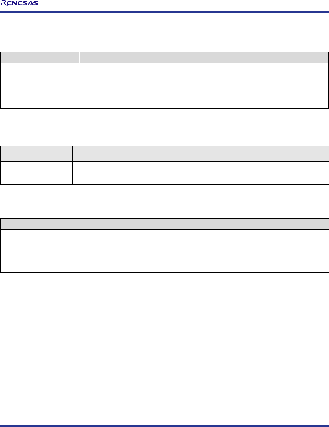
The Renesas WP15WBD-RK Evaluation Kit demonstrates 15W
wireless power transfer and bi-directional data communication
between a transmitter (Tx) board with the Renesas P9242-R3
Wireless Power Transmitter IC and a receiver (Rx) board with the
Renesas P9221-R3 Wireless Power Receiver IC. The bi-directional
data communication channel enables users to authenticate a
wirelessly charged receiver device with a specific charging
transmitter base or to transfer system data without any additional
hardware.
This evaluation kit adds bi-directional communication to Renesas’
standard, WPC 1.2-compliant, 15W transmitter P9242-R and
receiver P9221-R evaluation kits without compromising any
existing features. Its main contents are the transmitter P9242-R3-
EVK Evaluation Board and the receiver P9221-R3-EVK Evaluation
Board.
In customer end systems, the transmitter and receiver boards need
to have external microcontrollers (MCU) to orchestrate the
bi-directional communication. The MCU on the receiver board
loads data into the user outgoing data registers and triggers the
communication by writing to the Command register. The transmitter
receives the data and interrupts the external MCU on the trans-
mitter pad. The transmitter follows the same procedure to send the
data to the receiver. There are no external MCU’s on the
P9242-R3-EVK and P9221-R3-EVK Evaluation Boards. Instead,
IDT I2C Lite, an intuitive I2C-based graphical user interface (GUI),
and two USB-to-I2C dongles are used to emulate external MCUs.
The USB-to-I2C dongles are included in the kit. The latest version
of the IDT I2C Lite software is available on the IDT webpage.
This manual focuses on demonstrating the bi-directional data com-
munication features of the P9242-R3 and P9221-R3. The P9242-
R3-EVK and P9221-R3-EVK offer the flexibility to program param-
eters such as the over-current limit and foreign-object detection
(FOD) limits by changing resistors. Refer to the user manuals for
the P9242-R-EVK Transmitter Evaluation Board and P9221-R-EVK
Receiver Evaluation Board for more details related to programming
parameters.
*
Allegro® is a trademark of Cadence Systems.
Features
Supports bi-directional data communication
Enables device authentication and system data transfer
Up to 15W of power transfer
87% end-to-end efficiency
Flexibility to program parameters
Intuitive IDT I2C Lite GUI
Base kit is WPC-1.2-compliant
Kit Contents
P9242-R3-EVK V 2.1Transmitter Evaluation Board
P9221-R3-EVK V2.2 Receiver Evaluation Board
Two USB-to-I2C Dongles
Adapter: 12V/2A AC
Additional Support
This flexible, turn-key reference design is supported by online
design resources to significantly expedite the design-in effort and
enable rapid prototyping:
Schematics
Allegro
®
*
layout files
System Block Diagram

WP15WBD-RK Bi-directional Data Transfer Evaluation Kit User Manual for the P9221-R3 and P9242-R3
© 2020 Renesas Electronics Corporation
2
April 3, 2020
Important Notes
Disclaimer
Integrated Device Technology, Inc. and its affiliated companies (herein referred to as “IDT”) shall not be liable for any damages arising out of defects resulting from
(i) delivered hardware or software
(ii) non-observance of instructions contained in this manual and in any other documentation provided to user, or
(iii) misuse, abuse, use under abnormal conditions, or alteration by anyone other than IDT.
TO THE EXTENT PERMITTED BY LAW, IDT HEREBY EXPRESSLY DISCLAIMS AND USER EXPRESSLY WAIVES ANY AND ALL WARRANTIES, WHETHER
EXPRESS, IMPLIED, OR STATUTORY, INCLUDING, WITHOUT LIMITATION, IMPLIED WARRANTIES OF MERCHANTABILITY AND OF FITNESS FOR A
PARTICULAR PURPOSE, STATUTORY WARRANTY OF NON-INFRINGEMENT, AND ANY OTHER WARRANTY THAT MAY ARISE BY REASON OF USAGE
OF TRADE, CUSTOM, OR COURSE OF DEALING.
Restrictions in Use
Renesas’ WP15WBD-RK Evaluation Kit is designed for evaluation purposes only. It must not be used for module production or production test setups.
Contents
1. Setup ............................................................................................................................................................................................................4
1.1 Required or Recommended User Equipment ......................................................................................................................................4
1.2 Required Software on Computer .........................................................................................................................................................4
1.2.1 Software Installation .............................................................................................................................................................4
1.3 Kit Hardware Connections ...................................................................................................................................................................5
2. Usage Guide .................................................................................................................................................................................................7
2.1 Overview of the P9221-R3-EVK ..........................................................................................................................................................7
2.2 Overview of the P9242-R3-EVK ..........................................................................................................................................................8
3. Evaluating Bi Directional Data Communication ..........................................................................................................................................10
3.1 Transferring Data from the Receiver to the Transmitter ....................................................................................................................10
3.2 Transferring Data from the Transmitter to the Receiver ....................................................................................................................12
4. Schematics, Bill of Materials (BOM), and Board Layout .............................................................................................................................13
4.1 P9221-R3-EVK Evaluation Board Schematics V2.2 ..........................................................................................................................13
4.2 P9242-R3-EVK Evaluation Board Schematics V2.1 ..........................................................................................................................14
5. Bill of Materials (BOM) ................................................................................................................................................................................15
6. Partner Products Information ......................................................................................................................................................................19
6.1 Evaluation Kits ...................................................................................................................................................................................19
6.2 Transmitter Coils ...............................................................................................................................................................................19
6.3 Receiver Coils ...................................................................................................................................................................................20
7. Ordering Information ...................................................................................................................................................................................20
8. Revision History ..........................................................................................................................................................................................20

WP15WBD-RK Bi-directional Data Transfer Evaluation Kit User Manual for the P9221-R3 and P9242-R3
© 2020 Renesas Electronics Corporation
3
April 3, 2020
List of Figures
Figure 1. Windows Device Manager Display for Troubleshooting the USB Connection .....................................................................................4
Figure 2. Evaluation Kit Connections using the P9242-R3 Transmitter Evaluation Board and the P9221-R3 Receiver Evaluation Board ........5
Figure 3. I2C Header Connection to the P9221-R3-EVK Receiver Board ..........................................................................................................6
Figure 4. I2C Header Connection to the P9242-R3-EVK Transmitter Board ......................................................................................................6
Figure 5. I2C Dongle Header ..............................................................................................................................................................................6
Figure 6. P9221-R3 V2.2 Evaluation Board Features.........................................................................................................................................7
Figure 7. P9242-R3 V2.1 Evaluation Board Features.........................................................................................................................................8
Figure 8. P9242-R3 V2.1 Evaluation Board Details ............................................................................................................................................9
Figure 9. IDT I2C Lite Software Overview ........................................................................................................................................................10
List of Tables
Table 1. P9221-R3-EVK BOM V2.2 ................................................................................................................................................................15
Table 2. P9242-R3-EVK BOM V2.1 ................................................................................................................................................................16
Table 3. Recommended Transmitter Coil Manufactures .................................................................................................................................19
Table 4. Recommended Receiver Coil Manufacturers ....................................................................................................................................20

WP15WBD-RK Bi-directional Data Transfer Evaluation Kit User Manual for the P9221-R3 and P9242-R3
© 2020 Renesas Electronics Corporation
4
April 3, 2020
1. Setup
1.1 Required or Recommended User Equipment
The following additional lab equipment is required for using the kit:
Computer with the Windows® 7 or Windows® 10 operating system.
Note: An optional second computer can expedite the evaluation. For this option, a second USB-to-I2C dongle is provided in the kit. In this
case, repeat the setup procedures in section 1.2 for the second computer using the second dongle.
Oscilloscope
Multimeter
Power cables
1.2 Required Software on Computer
Visit the WP15WBD-RK website at www.IDT.com/WP15WBD-RK, and download latest version of the IDT I2C Lite software, script files, and
USB drivers from the IDT website. The software provides an intuitive graphical user interface for sending I2C commands using the USB-to-I2C
dongle shipped with the Evaluation Kit.
1.2.1 Software Installation
Follow these procedures to install the software:
1. Do not connect the USB-to-I2C dongle before installing the software.
2. Run the downloaded USB Drivers Setup executable file and follow the user prompts to install the USB drivers.
3. After finishing the setup of the USB drivers, connect one of the USB-to-I2C dongles to the USB port. Wait for a few moments to let
Windows
®
map the drivers for the dongle.
4. Open the Device Manager from the Windows control panel and check the devices listed under “Universal Serial Bus controllers”
section. “FT4222H Interface A” and “FT4222H Interface B” should appear in this section as shown in Figure 1.
5. Run the IDT I2C Lite Setup file and follow the user prompts to install the IDT I2C Lite software.
6. Place the downloaded script files in the C:\Users\...\AppData\Roaming\IDT I2C Lite folder to expedite loading the script files into the
IDT I2C Lite software. These scripts contain a series of I2C commands to send and receive data on the receiver and transmitter.
Figure 1. Windows Device Manager Display for Troubleshooting the USB Connection

WP15WBD-RK Bi-directional Data Transfer Evaluation Kit User Manual for the P9221-R3 and P9242-R3
© 2020 Renesas Electronics Corporation
5
April 3, 2020
1.3 Kit Hardware Connections
Follow these procedures to set up the kit as shown in Figure 2.
1. Plug the 12V adapter or user’s power supply into the J3 barrel connector on the bottom of the P9242-R3-EVK board (see Figure 7).
2. Place the P9221-R3-EVK on the transmitter (TX) pad with the components facing up as shown in Figure 2.
3. Verify that the two green LEDs identified in Figure 2 are illuminated indicating that coupling has been established.
4. Connect wires to the VOUT and GND test points on the P9221-R3-EVK receiver to measure the output voltage (see Figure 6) and apply
a load requiring less than the programmed current limit.
5. Connect the USB-to-I2C dongle to the computer’s USB port. If using a second computer, connect the second dongle to its USB port.
6. To send I2C commands to the P9221-R3-EVK, connect the I2C header on one of the connected dongles to J1 on the P9221-R3-EVK as
shown in Figure 3. The black wire on the dongle should be on the GND pin of the J1 Header. See sections 3.1 and 3.2 for detailed
instructions.
7. To send I2C commands to the P9242-R3-EVK, connect the I2C header on one of the connected dongles to J2 on the P9242-R3-EVK as
shown in Figure 4. The black wire on the dongle should be on the GND pin of the J2 header. See sections 3.1 and 3.2 for detailed
instructions.
Figure 2. Evaluation Kit Connections using the P9242-R3 Transmitter Evaluation Board and the
P9221-R3 Receiver Evaluation Board
P9242-R3-EVK
Transmitter Coil
P9221-R3-EVK
Green LEDs illuminate when
connection has been established.
Note: The buzzer shown on the P9242-R3-EVK is not placed for this kit.

WP15WBD-RK Bi-directional Data Transfer Evaluation Kit User Manual for the P9221-R3 and P9242-R3
© 2020 Renesas Electronics Corporation
6
April 3, 2020
Figure 3. I2C Header Connection to the P9221-R3-EVK Receiver Board
J1 Header with I2C Port
Dongle’s I2C Header
Black wire must be on the
GND pin of J1.
GND pin on J1
Figure 4. I2C Header Connection to the P9242-R3-EVK Transmitter Board
J2 Header with I2C Port
Dongle I2C Header
Black wire must be on the
GND pin of J2.
Figure 5. I2C Dongle Header
Blank
SCL
SDA
GND

WP15WBD-RK Bi-directional Data Transfer Evaluation Kit User Manual for the P9221-R3 and P9242-R3
© 2020 Renesas Electronics Corporation
7
April 3, 2020
2. Usage Guide
2.1 Overview of the P9221-R3-EVK
Figure 6. P9221-R3 V2.2 Evaluation Board Features
FOD Offset
Adjustment
(RPO)
External Temperature
Sensing Resistor
Output Voltage Adjustment (VOSET)
FOD Gain
Adjustment
(RPG)
Over-Current
Limit Adjustment
(ILIM)
Y- Alignment Guide Voltage (ALGY)
X- Alignment Guide Voltage (ALGX)
SCL SDA GND
GND
VRECT
GND
VOUT
Receiver Coil
IDT P9221-R3 IC
Interrupt Flag
J1
Header

WP15WBD-RK Bi-directional Data Transfer Evaluation Kit User Manual for the P9221-R3 and P9242-R3
© 2020 Renesas Electronics Corporation
8
April 3, 2020
2.2 Overview of the P9242-R3-EVK
Figure 7. P9242-R3 V2.1 Evaluation Board Features
P9242-RB Main IC
LED1 and LED2 Pattern Indicators
Vin Power Connector: Micro-USB
J3 Vin Power Barrel Connector
(see the bottom of the board)
Tx Coil
J2 I2C Header J5
MP-A2
Coil
Note: The P9242-RB IC is used on the P9242-R3 V2.1 Evaluation board instead of the P9242-R3 IC. The P9242-R3 has bi-directional
communication firmware pre-programmed into its one-time programmable memory and does not allow the firmware to be customized. The
P9242-RB offers a pre-programmed bootloader that must be used in conjunction with an external flash. Bidirectional communications firmware
is loaded into the external flash. The firmware can be customized in external flash. There is no functionality difference between the P9242-R3
V2.1 Evaluation board with P9242-R3 IC and the P9242-RB with external flash.

WP15WBD-RK Bi-directional Data Transfer Evaluation Kit User Manual for the P9221-R3 and P9242-R3
© 2020 Renesas Electronics Corporation
9
April 3, 2020
Figure 8. P9242-R3 V2.1 Evaluation Board Details

WP15WBD-RK Bi-directional Data Transfer Evaluation Kit User Manual for the P9221-R3 and P9242-R3
© 2020 Renesas Electronics Corporation
10
April 3, 2020
3. Evaluating Bi Directional Data Communication
3.1 Transferring Data from the Receiver to the Transmitter
To send the data from the P9221-R3 to the P9242-R3, the external microcontroller (MCU) on the receiver loads data into the user outgoing
data registers of the P9221-R3 and triggers the communication by writing to the Command register of the P9221-R3 via the I2C bus. The
P9242-R3 receives the data and interrupts the external MCU on the transmitter pad. The external MCU on the transmitter pad reads the user
incoming data registers via the I2C bus after it receives the interrupt. More details on the data transfer algorithm are in the P9221-R3 and
P9242-R3 datasheets.
There are no external MCUs on the receiver and transmitter evaluation boards in the WP15WBD-RD Evaluation Kit. Instead the IDT I2C Lite
software and USB-to-I2C dongles are used to simulate an external MCU. The USB-to-I2C dongle does not have the capability to generate
interrupts for the IDT I2C Lite software, so it is necessary to poll the Status register to check for incoming data or probe the INT
̅
̅
̅
̅
test point on
the P9242-R3-EVK (IO_B4 test point) using an oscilloscope.
Follow these procedures to transfer the data from the receiver board to the transmitter board:
1. Power up the transmitter and receiver evaluation boards by following the steps in section 1.3.
2. Verify that the green LEDs (identified in Figure 2) on both the transmitter and receiver boards are illuminated indicating that devices are
in the power transfer phase. Bi-directional communication is enabled only when the devices are in the power transfer phase.
3. Connect the USB-to-I2C dongle to the computer’s USB port and connect the I2C header of the dongle to J1 on the P9221-R3-EVK board
as shown in Figure 3. The black wire on the dongle should be on the GND pin of the J1 header.
4. Open the IDT I2C Lite GUI by going to the Windows start menu: IDT GUI Application IDT I2C Lite. Figure 9 shows an overview.
Figure 9.
IDT I2C Lite
Software Overview
USB-to-I2C Dongle
Connection Status
Selected Device
Connection Status
Version #
Starting Register
Address
Number of Bytes to Read or
Write Including Starting Address
Continuously Run
the Same Script
Add or Remove I2C
Commands in the Script
Clear Data Fields
Selected Device
Connection Status
USB-to-I2C Dongle
Connection StatusOpen and Close Scripts
I2C Address of
Selected DeviceSelect Device
Run all Commands
in the Script
Delay between
Consecutive I2C
Transactions
Log I2C R/W Results

WP15WBD-RK Bi-directional Data Transfer Evaluation Kit User Manual for the P9221-R3 and P9242-R3
© 2020 Renesas Electronics Corporation
11
April 3, 2020
5. Verify the proper USB dongle connection by checking the USB icon status in the top right corner of the GUI. When the USB dongle is
properly connected, the USB icon should be bright blue and the bottom left corner should indicate “IDT dongle connected.”
6. Select “P9221 RX” from the “Device” drop-down menu in the GUI.
7. Verify that the proper P9221-R3-EVK connection is recognized by the GUI by checking the device icon in the top right corner of the GUI.
When the P9221-R3-EVK is properly connected, the selected device icon should be bright blue and the message in the middle of the
bottom status bar in the GUI should indicate “P9221 connected.”
8. Click “Open Script” from the “File” menu in the top left corner of the GUI, and navigate to the “Send 8 bytes from Rx to Tx” script. This
script has all the I2C commands required to send the data from the P9221-R3 to the P9242-R3. The script can be customized by using
the “+” and “–” buttons in the GUI.
9. Click the “Run all” button to run all the I2C commands in the script to send the data from the P9221-R3 to the P9242-R3.
10. If using only one computer, gently disconnect the dongle I2C header from the receiver board, and connect the I2C header to J2 of the
P9242-R3-EVK transmitter board as shown in Figure 4. The black wire on the dongle should be on the GND pin on the J2 header.
If using two computers, follow the subsequent steps on the second computer to read the data.
11. Select “P9242 TX” from the “Device” drop down menu in the GUI.
12. Verify the proper P9242-R3-EVK connection to GUI by checking the selected device icon in the top right corner of the GUI. When the
P9242-R3-EVK is properly connected, the icon should be in bright blue color and the bottom status bar in the GUI should indicate “P9242
connected.”
13. Click “Open Script” from the “File” menu in the top left corner of the GUI, and navigate to the “Read 8 bytes of data on Tx” script. This
script has all the I2C commands required to read data coming into the P9242-R3. The script can be customized by using the “+” and “–”
buttons in the GUI.
14. Click the “Run all” button to run all the I2C commands in the script to read the incoming data in the P9242-R3.
15. Verify that the incoming data on the P9242-R3 matches the P9221-R3 outgoing data.

WP15WBD-RK Bi-directional Data Transfer Evaluation Kit User Manual for the P9221-R3 and P9242-R3
© 2020 Renesas Electronics Corporation
12
April 3, 2020
3.2 Transferring Data from the Transmitter to the Receiver
To send the data from the P9242-R3 to the P9221-R3, the external microcontroller (MCU) on the transmitter loads data into the user outgoing
data registers of the P9242-R3 and triggers the communication by writing to the Command register of the P242-R3 via the I2C bus. The P9221-
R3 receives the data and interrupts the external MCU on the receiver board. The external MCU on the receiver board reads the user incoming
data registers via the I2C bus after it receives the interrupt. More details on the data transfer algorithm are in the P9221-R3 and P9242-R3
datasheets.
There are no external MCU’s on the receiver and transmitter evaluation boards in the WP15WBD-RD Evaluation Kit. Instead, the IDT I2C Lite
software and USB-to-I2C dongle are used to simulate an external MCU. The USB-to-I2C dongle does not have the capability to generate
interrupts for the IDT I2C Lite software, so it is necessary to poll the Data Received Status register to check for incoming data or probe the
interrupt pin on the P9221-R3 (pin 2 on the J1 header on the P9221-R3-EVK board) using an oscilloscope.
Follow these procedures to transfer the data from the transmitter board to the receiver board:
1. Power up the transmitter and receiver evaluation boards by following the steps in section 1.3.
2. Verify that the green LEDs (identified in Figure 2) on both transmitter and receiver boards are illuminated indicating that devices are in
the power transfer phase. Bi-directional communication is enabled only when the devices are in the power transfer phase.
3. Connect the USB-to-I2C dongle to the computer’s USB port and connect the I2C header of the dongle to J2 on the P9242-R3-EVK board
as shown in Figure 4. The black wire on the dongle should be on the GND pin of the J2 header.
4. Open the IDT I2C Lite GUI by going to the Windows start menu: IDT GUI Application IDT I2C Lite. See Figure 9.
5. Verify the proper USB dongle connection by checking the USB icon status in the top right corner of the GUI. When the USB dongle is
properly connected, the USB icon should be bright blue and the bottom left corner should indicate “IDT dongle connected.”
6. Select “P9242 TX” from the “Device” drop-down menu in the GUI.
7. Verify that the proper P9242-R3-EVK connection is recognized by the GUI by checking the selected device icon in the top right corner of
the GUI. When the P9242-R3-EVK evaluation board is properly connected, the icon should be bright blue and the message in the middle
of the bottom status bar in the GUI should indicate “P9242 connected.”
8. Click “Open Script” from the “File” menu in the top left corner of the GUI, and navigate to the “Send 2 bytes from Tx to Rx” script. This
script has all the I2C commands required to send the data from the P9242-R3 to the P9221-R3. The script can be customized by using
the “+” and “–” buttons in the GUI.
9. Click the “Run all” button to run all the I2C commands in the script to send the data from the P9242-R3 to the P9221-R3.
10. If using only one computer, gently disconnect the dongle I2C header from the transmitter board, and connect the I2C header to J1 on the
P9221-R3-EVK receiver board as shown in Figure 3. The black wire on the dongle should be on the GND pin of the J1 header.
If using two computers, follow the subsequent steps on the second computer to read the data.
11. Select “P9221 RX” from the “Device” drop-down menu in the GUI.
12. Verify the proper P9221-R3-EVK connection to the GUI by checking the selected device icon in the top right corner of the GUI. When the
P9221-R3-EVK evaluation board is properly connected, the icon should be bright blue and the bottom status bar in the GUI should
indicate “P9221 connected.”
13. Click “Open Script” from the “File” menu in the top left corner of the GUI, and navigate to the “Read 2 bytes of data on Rx” script. This
script has all the I2C commands required to read data coming into the P9221-R3. The script can be customized by using the “+” and “–”
buttons in the GUI.
14. Click the “Run all” button to run all the I2C commands in the script to read the data coming into the P9221-R3.
15. Verify that the incoming data on the P9221-R3 matches the P9242-R3 outgoing data.

WP15WBD-RK Bi-directional Data Transfer Evaluation Kit User Manual for the P9221-R3 and P9242-R3
© 2020 Renesas Electronics Corporation
13
April 3, 2020
4. Schematics, Bill of Materials (BOM), and Board Layout
4.1 P9221-R3-EVK Evaluation Board Schematics V2.2
D1
LED
C12
NP
C10
10uF
INT
INT
SDA
C9
3.3nF
R18
NP
VDD5V
D6
5.1V
R8 0
RSV1
C25
NP
ALGX
R33
NP
R39
10k
C19
0.1uF
C21
10uF
C16
15nF
U1
P9221-R
COMM1
A1
COMM2
A6
RSV4
B1
RSV5
B6
EN
B5
ALIGNX
A2
SCL
A3
VOSET/Q-Fact
A4
RPPG
A5
SDA
B3
ALIGNY
B2
ILIM
B4
RPPO
C4
RSV6
C5
OUT
D1
INT
C3
SINK
C2
OUT1
D2
OUT2
D3
OUT3
D4
OUT4
D5
OUT5
D6
VRECT
E1
VRECT1
E2
VRECT2
E5
VRECT3
E6
VRECT4
F2
VRECT5
F3
VRECT6
F4
VRECT7
F5
AC1
G2
AC1_1
H1
AC1_2
H2
AC2
G5
AC2_1
H5
AC2_2
H6
BST1
G1
BST2
G6
PGND
C1
PGND1
C6
PGND2
J1
PGND3
J2
PGND4
J3
PGND5
J4
PGND6
J5
PGND7
J6
VDD5V
F1
VDD18
F6
RSV3
G3
RSV2
H3
RSV1
G4
TS/EOC
H4
C20
1uF
/EN
R19
10K
I2CRAIL
VOUT
VOSET
P9221-R MM EV Board V2.2
C31
0.1uF
C8
15nF
VRECT
R35 0
J1
I2C
1
2
3
4
5
L1
SCL
R28
NP
R17 10k
VPP18
R42
NP
VDD5V
R22
NP
R2
36
R14
5.1k
C3
100nF/50V
RPO
C11
10uF
RSV1
R13
5.1k
TS
VOUT
C23
0.1uF
GND1
R16 10K
VRECT
R29
10K
C7
NP
VOSNS
ILIM R34
10k
R23
10k
C22
10uF
VDD5V
R38
10K
RX Power Coil
AlignX coil
C18
1uF
C6
47nF
VPP18
Vrect
R1
5.1k
ALGY
TS
C2
100nF/50V
D7
5.1V
U2
NP
A0
1
A1
2
A2
3
VSS
4
SDA
5
SCL
6
WP
7
VCC
8
E_PAD
9
VPP18
RTS
NP
VPP18
C1
100nF/50V
AlignY coil
WP
C5
100nF/50V
R41
NP
LC
SDA
INT
R27
10K
VOUT
C33
10uF
DEN
R30
NP
AC2T
TS
C15
NP GND
SCL
R6 NP
R15 10K
GCOM
AC2
RPG
C14
47nF

WP15WBD-RK Bi-directional Data Transfer Evaluation Kit User Manual for the P9221-R3 and P9242-R3
© 2020 Renesas Electronics Corporation
14
April 3, 2020
4.2 P9242-R3-EVK Evaluation Board Schematics V2.1
ENB
SCL
IO_B1
R23
10K
Debugg, for development only
C4
0.1uF
R10
390K
R22 NP
VSNS_IN
C28
22uF
Q7
2N7002
VLX2
LDO33
C12 1uF
GND
INT_TP
LDO33
D-
R33
3
C16
1uF
R13
10K
ILIM
R26
100K
C35
5.6nF
C30
0.1uF
R34
100K
Q_DRV2
LDO18
IO_A7
R39 0
Q_DRV1
LED2
VCC_5V
LED1
2 1
LDO33
ISNS_H
IO_B5
THIS DOCUMENT CONTAINS INFORMATION PROPRIETARY
TO Integrated Device Technology, Inc. (IDT).
USE OR DISCLOSURE WITHOUT THE
WRITTEN PERMISSION OF AN OFFICER OF
IDT IS EXPRESSLY FORBIDDEN
C2
0.1uF
TS
C11
22nF
IO_B1
R5
NP
GNDT1
LDO33
R6
10K
C41
10uF
Q2
DMG7430LFG
5
4
1
6
7
8
2
3
R41
10K
U2
NP
CS#
1
DO
2
WP#
3
GND
4
DI
5
CLK
6
HLD#
7
VCC
8
EPAD
9
VCOIL_OV
R1
1K
SDA
R36
0.1
R19 NP
LX1
Q8
2N7002
R44 NP
LED_PAT
C29
0.1uF
R42
10K
C10
22nF
VIN1
IO_B2
LX2
R11
200K
R30
100K
R31
100K
R32
100K
VIN
C34 0.1uF
IO_B2
D2
BAV21W
VBRG
usb_id
C6
1uF
TX-Coil
assembly
C44
4.7u
LDO33
ISNS_H
R25
12
GND1
VIN
IO_B8
R46
5.1k
R29
12
GND3
LDO33
C13
0.1uF
C14
10uF
C25 NP
D-
R28
12
D1
BAV21W
IO_B1
R24
NP
R40 NP
C9
56p
SCL
GND2
R18 0.02
C36
NP
LDO33
SW_BRG2
VCC_5V
C1
0.1uF
J3
AC_Adapter
C31
10uF
Programming Connector
C7
56p
ISNS_OUT
C15
0.1uF
C24 47nF
LOAD
R38 0
VCOIL
IO_B0
LED_PAT
C22 22nF
J4
R14
2.4K
IO_A1
Q1
DMG7430LFG
5
4
1
6
7
8
2
3
R21
10
Q_DRV2
Q6
SIA453EDJ-T1-GE3
1
2
3
4
7
5
6
8
IO_B3
SDA
C8
6.8nF
C43
1uF
C23 68nF
SDA
R43 10K
IO_B3
IO_B0
C19
5.6nF
C42
0.1uF
R8
100K
RED
R12
390K
IO_B0
IO_A6
R3
1K
IO_B6
R48 10K
vs3
GND4
R9 NP
GNDT2
LED2
2 1
C20 100nF
Q4
DMG7430LFG
5
4
1
6
7
8
2
3
D+
IO_B3
C3
0.1uF
OVP_CTL
VLX1
R45
220
VINT1
C27
1uF
Title
Size Document Number Rev
Date: Sheet of
2.2
P9242-R3 MM Board V 2.1
Custom
1 1Wednesday, October 11, 2017
Q3
DMG7430LFG
5
4
1
6
7
8
2
3
LDO33
V_BRIDGE
C40
10uF
IO_A5
vs2
LDO33
t
RTH1
R15
10
ILIM
LED_PAT
L2
NP
1
2 3
4
C17
680p
ILIM
OVP_CTL
VINT2
ISNS_IN
C32
22uF
ISNS_L
LDO33
SLD
SLD
VCC
D-
D+
ID
GND
J1
usb_micro_ab
1
2
3
4
56
7
8
9
10
11
PZ1
NP
1
1
2
2
R47
5.1k
VCC5V
R16
10K
C37
10uF
IO_B4
C18
1nF
P9242-R3
U1
EN
1
GND
2
PREG
3
VIN
4
SW_S
5
GND
6
LDO33
7
VIN_LDO
8
LDO18
9
LED1
10
LED2
11
VDDIO
12
RSV
25
RSV
26
RSV
27
RSV
28
/INT
29
GH_BRG2
30
BST_BRG2
31
SW_BRG2
32
GL_BRG2
33
GND
34
GL_BRG1
35
SW_BRG1
36
EP
49
BST_ BRG1
37
GH_BRG1
38
DRV_VIN
39
VBRG_IN
40
GND
41
42
RSV
RSV
43
VDEM1
44
IDEMI
45
ISNS_OUT
46
CSN
47
CSP
48
D-
13
D+
14
SCL
15
SDA
16
ILIM/FOD
17
LED/Q-Fact
18
VCOIL
19
TS
20
LOAD
21
OVP_CTL
22
Q_DRV1
23
Q_DRV2
24
C33
0.1uF
Q_DRV1
C38
10uF
LDO33
IO_A4
R37
0.1
LDO33
C39
5.6nF
R27
12
LDO18
ISNS_L
VCOIL_OV
J2
68000-105HLF
1
1
2
2
3
3
4
4
5
5
R7 1K
IO_B2
J5
1
1
2
2
3
3
4
4
VIN
IO_A0
INT_TP
D+
VIN
GREEN
Q5
2N7002
R4
680
R20 10K
IO_B7
R35 200K
C21
0.1uF
LED1
C5
10uF
C26
0.1uF
SCL
L1 4.7uH

WP15WBD-RK Bi-directional Data Transfer Evaluation Kit User Manual for the P9221-R3 and P9242-R3
© 2020 Renesas Electronics Corporation
15
April 3, 2020
5. Bill of Materials (BOM)
Table 1. P9221-R3-EVK BOM V2.2
Item
Quantity
Reference
Value
Description
Part Number
PCB Footprint
1
16
AC2T, VDD5V, VPP18,
VOSET, TS, SDA, SCL, RPO,
RPG, INT, ILIM, GCOM,
DEN, ALGY, ALGX, /EN
PTH_TP
Test Pad
10MIL_35PAD
2
2
AC2, LC
NP
Test Point
test_pt_sm_135x70
3
4
C1, C2, C3, C5
100nF/
50V
CAP CER 0.1UF 50V X5R 0402
GRM155R61H104KE19D
0402
4
2
C6, C14
47nF
CAP CER 0.047UF 50V X7R 0402
C1005X7R1H473K050BB
0402
5
2
C7, C15
NP
CAP CER 0.047UF 50V X7R 0402
C1005X7R1H473K050BB
0402
6
2
C8, C16
15nF
CAP CER 0.015UF 50V X7R 0402
GRM155R71H153KA12J
0402
7
1
C9
3.3nF
CAP CER 3300PF 50V X7R 0402
CL05B332KB5NNNC
0402
8
5
C10, C11, C21, C22, C33
10µF
CAP CER 10UF 25V X5R 0603
CL10A106MA8NRNC
0603
9
1
C12
NP
CAP CER 10UF 25V X5R 0603
CL10A106MA8NRNC
0603
10
1
C18
NP
CAP CER 1UF 10V X5R 0402
GRM155R61A105KE15D
0402
11
1
C20
1µF
CAP CER 1UF 10V X5R 0402
GRM155R61A105KE15D
0402
12
3
C19, C25, C31
0.1µF
CAP CER 0.1UF 10V X5R 0201
C0603X5R1A104K030BC
0201
13
1
C23
0.1µF
CAP CER 0.1UF 25V X5R 0201
CL03A104KA3NNNC
0201
14
1
D1
LED
LED GREEN CLEAR 0603 SMD
150060GS75000
0603_diode
15
2
D6,D7
5.1V
DIODE ZENER 5.1V 100MW 0201
CZRZ5V1B-HF
0201
16
5
GND1, VRECT, VOUT,
VOSNS, GND
Test
Point
TEST POINT PC MINIATURE SMT
5015
test_pt_sm_135x70
17
1
L1
RX coil
AMOTECH, Rx Power Coil
ASC-504060M22-S00
10MIL_35PAD
18
1
J1
NP
HEADER_1X5_0P1PITCH60P42D
68002-205HLF
header_1x5_0p1Pitch60
p42d
19
1
RTS
NP
NTC2
20
3
R1, R13, R14
5.1kΩ
RES SMD 5.1K OHM 5% 1/16W
0402
MCR01MRTJ512
0402
21
1
R2
36Ω
RES SMD 36 OHM 5% 1/2W 0805
ERJ-P06J360V
0805
22
1
R6
NP
RES SMD 0.0OHM 1/10W 0402
ERJ-2GE0R00X
0402
23
1
R8
0Ω
RES SMD 0.0OHM 1/10W 0402
ERJ-2GE0R00X
0402
24
2
R15, R16
10kΩ
RES SMD 10KOHM 1% 1/10W
0603
RC0603FR-0710KL
0603
25
10
R17, R19, R23, R27, R28,
R29, R30, R34, R38, R39
10kΩ
RES SMD 10K OHM 5% 1/10W
0402
ERJ-2GEJ103X
0402
26
3
R18, R22, ,R33
NP
RES SMD 10K OHM 5% 1/10W
0402
ERJ-2GEJ103X
0402
27
1
R35
0Ω
RES SMD 0.0OHM JUMPER
1/10W 0603
MCR03EZPJ000
0603

WP15WBD-RK Bi-directional Data Transfer Evaluation Kit User Manual for the P9221-R3 and P9242-R3
© 2020 Renesas Electronics Corporation
16
April 3, 2020
Item
Quantity
Reference
Value
Description
Part Number
PCB Footprint
28
1
U1
P9221-R3
Wireless power receiver
P9221-R3
csp52_2p64x3p94_0p4mm
29
1
U2
NP
IC EEPROM 128KBIT 400KHZ
8TDFN
24AA128T-I/MNY
TDFN08
Table 2. P9242-R3-EVK BOM V2.1
Item
Quantity
Reference
Value
Description
Part Number
PCB Footprint
1
12
C1, C2, C3, C4, C13, C15,
C21, C26, C29, C30, C33,
C34
0.1µF
CAP CER 0.1µF 25V 10% X7R
0402
C1005X7R1E104K050BB
0402
2
7
C5, C14, C31, C37, C38,
C40, C41
10µF
CAP CER 10µF 25V 20% X5R
0603
C1608X5R1E106M080AC
0603
3
4
C6, C12, C16, C27
1µF
CAP CER 1µF 25V 20% X5R 0402
C1005X5R1E105M050BC
0402
4
2
C7, C9
56pF
CAP CER 56PF 50V NP0 0402
CL05C560JB5NNNC
0402
5
1
C8
6.8nF
CAP CER 6800PF 25V X7R 0402
GRM155R71E682KA01D
0402
6
2
C10, C11
22nF
0.022µF 50V Ceramic Capacitor
X7R 0603
GCM188R71H223KA37D
0603
7
1
C17
680pF
CAP CER 680PF 50V X7R 0402
CL05B681KB5NNNC
0402
8
1
C18
1nF
CAP CER 1000pF ±10% 50V X7R
0402
GRM155R71H102KA01D
0402
9
3
C19, C35, C39
5.6nF
5600pF 100V Ceramic Capacitor
C0G, NP0 0603
C1608C0G2A562J080AC
0603
10
1
C20
100nF
CAP CER 0.1µF 100V C0G 1206
C3216C0G2A104K160AC
1206
11
1
C22
22nF
CAP CER 0.022µF 50V 10% X7R
0402
GRM155R71H223KA12D
0402
12
1
C23
68nF
CAP CER 0.068µF 100V NP0 1206
C3216C0G2A683K160AC
1206
13
1
C24
47nF
CAP CER 0.047µF 100V NP0 1206
C3216C0G2A473J115AC
1206
14
1
C25
NP
CAP CER 10000PF 100V C0G
1206
C3216C0G2A103J115AA
1206
15
2
C28, C32
22µF
CAP CER 22µF 25V 20% X5R
1206
GRM31CR61E226KE15L
1206
16
1
C36
0.1uF
CAP CER 0.1µF 25V 10% X7R
0402
C1005X7R1E104K050BB
0402
17
1
C42
0.1µF
0.10µF 50V Ceramic Capacitor
X7R 0603
GRM188R71H104KA93D
0603
18
1
C43
1µF
1µF 25V Ceramic Capacitor X5R
0603
GRM188R61E105KA12D
0603
19
1
C44
4.7µF
4.7µF 25V Ceramic Capacitor X5R
0603
GRM188R61E475KE11D
0603
20
2
D1, D2
BAV21W
DIODE GEN PURP 80V 125MA
DFN
BAV21W-7-F
sod123

WP15WBD-RK Bi-directional Data Transfer Evaluation Kit User Manual for the P9221-R3 and P9242-R3
© 2020 Renesas Electronics Corporation
17
April 3, 2020
Item
Quantity
Reference
Value
Description
Part Number
PCB Footprint
21
30
VLX1, VINT1, IO_B1, IO_A1,
GNDT1, vs2, VLX2, VINT2,
IO_B2, GNDT2, vs3, IO_B3,
IO_B4, IO_A4, VCC5V,
IO_B5, IO_A5, IO_B6,
IO_A6, IO_B7, IO_A7,
IO_B8, LDO18, LDO33,
VSNS_IN, VCOIL, VBRG,
IO_B0, IO_A0, ENB
PTH_TP
30 GAUGE WIRE PAD
NP
TEST_PT30DPAD
22
7
VIN1, GND1, GND2, GND3,
GND4, VIN, GND
TP
TEST POINT PC MINIATURE SMT
5015
test_pt_sm_135x70
23
1
J1
5P
CONN RCPT MCR USB AB SMD
TH SHLL
ZX62D-AB-5P8
usb_micro_ab
24
1
J2
68000-
105HLF
BERGSTIK II .100" SR STRAIGHT
68000-105HLF
sip5
25
1
J3
AC
Adapter
CONN POWER JACK 2.5X5.5MM
HI CUR
PJ-002AH
CONN_POWER_JACK5
_5MM
26
1
J4
TP
CONN HEADER 3POS .100" STR
GOLD
901200763
sip3
27
1
J5
SIP con
4-position header
961104-6404-AR
sip-4
28
1
LED1
LED
LED RED CLEAR 0603 SMD
150060RS75000
0603_diode
29
1
LED2
LED
LED GREEN CLEAR 0603 SMD
150060GS75000
0603_diode
30
2
LX1, LX2
NP
Tx coil assemble through hole
NA
TP_TXCoil
31
1
L1
4.7µH
FIXED IND 4.7µH 620MA 500
MOHM
CIG10W4R7MNC
L0603
32
1
L2
NP
Common mode EMI choke
ACM4520-901-2P-T-000
EMI_TDK_ACM4520L
33
1
PZ1
NP
BUZZER PIEZO 4KHZ 12.2MM PC
MNT
PS1240P02CT3
9235_buzzer
34
4
Q1, Q2, Q3, Q4
DMG74
30LFG
MOSFET N-CH 30V 10.5A
PWRDI3333
DMG7430LFG-7
powerdi3333_8ld_fet
35
3
Q5, Q7, Q8
2N7002
N-Channel 60-V (D-S) MOSFET
2N7002KT1G
SOT23_3
36
1
Q6
MOSFET
MOSFET P-CH 30V 24A PPAK
SC-70-6
SIA453EDJ-T1-GE3
sc70_6ld_fet
37
1
RTH1
NP
NTC thermistor 10k bead
NTCLE203E3103JB0
0805
38
3
R1, R3, R7
1kΩ
RES SMD 1K OHM 5% 1/16W
0402
RC0402JR-071KL
0402
39
1
R4
680Ω
RES SMD 680 OHM 5% 1/16W
0402
RC0402JR-07680RL
0402
40
1
R5
NP
RES SMD 0.0 OHM JUMPER
1/10W
RC0402JR-070RL
0402
41
9
R6, R13, , R16, R20, R23,
R41, R42, R43, R48
10kΩ
RES SMD 10K OHM 1% 1/10W
0402
RC0402FR-0710KL
0402
42
5
R8, R26, R30, R31, R32
100kΩ
RES SMD 100K OHM 5% 1/10W
0402
ERJ-2GEJ104X
0402

WP15WBD-RK Bi-directional Data Transfer Evaluation Kit User Manual for the P9221-R3 and P9242-R3
© 2020 Renesas Electronics Corporation
18
April 3, 2020
Item
Quantity
Reference
Value
Description
Part Number
PCB Footprint
43
1
R24
100K
RES SMD 100K OHM 5% 1/10W
0402
ERJ-2GEJ104X
0402
44
1
R9
NP
RES SMD 100 OHM 5% 1/10W
0603
RC0603JR-07100RL
0603
45
2
R10, R12
390kΩ
RES SMD 390K OHM 5% 1/10W
0603
ERJ-3GEYJ394V
0603
46
1
R14
2.4kΩ
RES SMD 2.4K OHM 5% 1/10W
0402
ERJ-2GEJ242X
0402
47
2
R11, R35
200kΩ
RES SMD 200K OHM 1% 1/10W
0603
RC1608F204CS
0603
48
2
R15, R21
10Ω
RES SMD 10 OHM 1% 1/10W
0402
ERJ-2RKF10R0X
0402
49
1
R18
0.02Ω
RES SMD 0.02 OHM 1% 1/8W
0805
WSL0805R0200FEA
0805
50
4
R19, R22, R40, R44
NP
RES SMD 10K OHM 1% 1/10W
0402
RC0402FR-0710KL
0402
51
4
R25, R27, R28, R29
12Ω
RES SMD 12 OHM 5% 1/10W
0402
ERJ-2GEJ120X
0402
52
1
R33
3Ω
RES SMD 3 OHM 1% 1/8W 0805
RC0805FR-073RL
0805
53
1
R34
100kΩ
RES SMD 100K OHM 1% 1/10W
0603
ERJ-3EKF1003V
0603
54
2
R36, R37
0.1Ω
RES SMD 0.1 OHM 5% 1/6W 0402
ERJ-2BSJR10X
0402
55
2
R38, R39
0Ω
RES SMD 0.0 OHM JUMPER
1/10W
RC0402JR-070RL
0402
56
1
R45
220Ω
RES SMD 220 OHM 1% 0.4W
0805
RC1206FR-07220RL
1206
57
2
R46, R47
5.1kΩ
RES SMD 5.1K OHM 5% 1/16W
0402
MCR01MRTJ512
0402
58
1
U1
[a]
P9242-RB
Transmitter (Bootloader Part)
P9242-RB
socketqfn_48_6x6_0p4
59
1
U2
W25X20
CLUXIG
SPIFLASH 2M-BIT 4KB UNIFORM
SECT
W25X20CLUXIG TR
uson_2x3_8LD
[a] The P9242-RB offers a pre-programmed bootloader that must be used in conjunction with an external flash. Bi-directional communications firmware
is loaded into the external flash. The firmware can be customized in external flash. There is no functionality difference between the P9242-R3 V2.1
Evaluation board with P9242-R3 IC and the P9242-RB with external flash.

WP15WBD-RK Bi-directional Data Transfer Evaluation Kit User Manual for the P9221-R3 and P9242-R3
© 2020 Renesas Electronics Corporation
19
April 3, 2020
6. Partner Products Information
6.1 Evaluation Kits
Renesas partnered with Wurth Elektronik to build a development kit for customers with the same bill of materials and reference designators as
the WP15WBD-RK. For more information on the development kit, see the Wurth Elecktronik website.
6.2 Transmitter Coils
Table 3. Recommended Transmitter Coil Manufactures
Output Power
Vendor
Part Number
Inductance at 100kHz
DCR at 20°C
15W
SUNLORD
SWA53N53H30C11B
10µH
50mΩ
15W
TDK
WT525225-12F2-MA2-G
10.6µH
40mΩ
15W
WURTH
760308103102
10µH
55mΩ
WP15WBD-RK Bi-directional Data Transfer Evaluation Kit User Manual for the P9221-R3 and P9242-R3
© 2020 Renesas Electronics Corporation
20
April 3, 2020
6.3 Receiver Coils
Table 4. Recommended Receiver Coil Manufacturers
Output Power
Vendor
Part Number
Inductance at 100kHz
ACR at 20°C
Series Resonant Capacitance
15W
AMOTECH
ASC-504060E00-S00
8.2µH
220mΩ
400nF
15W
TDK
WR424245-13K2-G
11.2µH
170mΩ
300nF
15W
SUNLORD
SWA50R40H06C02B
8.4µH
150mΩ
400nF
15W
WURTH
760308102207
8.0µH
80mΩ
400nF
7. Ordering Information
Orderable Part Number
Description
WP15WBD-RK
WP15WBD-RK Bi-directional Data Transfer Evaluation Kit including P9242-R3-EVK Transmitter Evaluation
Board, P9221-R3-EVK Receiver Evaluation Board, two USB to I2C Dongles, and 12V/2A AC Adapter.
8. Revision History
Revision Date
Description of Change
April 3, 2020
Added Partner Products Information
November 21, 2018
Updated Figure 7 (and added note below figure) and Figure 8
Updated Table 2
October 19, 2017
Initial release.

Corporate Headquarters
TOYOSU FORESIA, 3-2-24 Toyosu,
Koto-ku, Tokyo 135-0061, Japan
www.
renesas.com
Contact Information
For further information on a product, technology, the most
up-to-date version of a document, or your nearest sales
office, please visit www.renesas.com
/contact-us/.
Trademarks
Renesas and the Renesas logo are trademarks of Renesas
Electronics Corporation. All trademarks and registered
trademarks are the property of their respective owners.
IMPORTANT NOTICE AND DISCLAIMER
RENESAS ELECTRONICS CORPORATION AND ITS SUBSIDIARIES (“RENESAS”) PROVIDES TECHNICAL
SPECIFICATIONS AND RELIABILITY DATA (INCLUDING DATASHEETS), DESIGN RESOURCES (INCLUDING
REFERENCE DESIGNS), APPLICATION OR OTHER DESIGN ADVICE, WEB TOOLS, SAFETY INFORMATION, AND
OTHER RESOURCES “AS IS” AND WITH ALL FAULTS, AND DISCLAIMS ALL WARRANTIES, EXPRESS OR IMPLIED,
INCLUDING, WITHOUT LIMITATION, ANY IMPLIED WARRANTIES OF MERCHANTABILITY, FITNESS FOR A
PARTICULAR PURPOSE, OR NON-INFRINGEMENT OF THIRD-PARTY INTELLECTUAL PROPERTY RIGHTS.
These resources are intended for developers who are designing with Renesas products. You are solely responsible for (1)
selecting the appropriate products for your application, (2) designing, validating, and testing your application, and (3)
ensuring your application meets applicable standards, and any other safety, security, or other requirements. These
resources are subject to change without notice. Renesas grants you permission to use these resources only to develop an
application that uses Renesas products. Other reproduction or use of these resources is strictly prohibited. No license is
granted to any other Renesas intellectual property or to any third-party intellectual property. Renesas disclaims
responsibility for, and you will fully indemnify Renesas and its representatives against, any claims, damages, costs, losses,
or liabilities arising from your use of these resources. Renesas' products are provided only subject to Renesas' Terms and
Conditions of Sale or other applicable terms agreed to in writing. No use of any Renesas resources expands or otherwise
alters any applicable warranties or warranty disclaimers for these products.
(Disclaimer Rev.1.01 Jan 2024)
© 2024 Renesas Electronics Corporation. All rights reserved.
