
INSTALLATION AND
MAINTENANCE GUIDE
TL-1300 Rev A

Page 2
ENGLISH
Zodiac
®
Caretaker
TM
In-Floor Pool Cleaning System
|
Installation and Maintenance Guide
When installing and using this equipment, basic safety precautions should always be followed including
the following:
READ AND FOLLOW ALL INSTRUCTIONS.
Installation of electrical equipment should be performed by a licensed electrician and conform to all
National Electric Code (NEC), state and local law, ordinances, codes and regulations.
WARNING: To reduce the rick of electrical shock:
• Install all electrical equipment at least 10 ft. (3 m) from inside wall of pool or spa.
• Disconnect power before servicing this equipment.
• CAUTION: Use supply wires suitable for 140-167°F (60/75° C).
• CAUTION: Connect only to a circuit protected by a Class A ground fault circuit interrupter.
• Use copper conductors only.
WARNING: To reduce risk of injury, do not permit children to use this product unless they are closely
supervised at all times.
To guarantee complete cleaning and qualify the warranty, fax or email a Design Fact Sheet along
with a scaled pool plan for FREE In-Floor Design Service.
Email: [email protected]
Fax: (760) 597-1246
If the pool design or dimensions change during excavation, a new design
plan must be drawn.
Install the valve above ground and finished pool water level. Do not bury valve after installation.
Install cleaning heads and nozzles according to the Design Plan.
If pool includes an elevated spa, install a check valve on the line feeding the spa heads to avoid spa
draining. Install other check valves (as normal) to avoid spa return jets and suction lines from draining.
SAVE THESE INSTRUCTIONS.
For customer service or support:
• For on-line support: www.zodiacpoolsystems.com
• To contact Zodiac: US and Canada
Customer Service
2620 Commerce Way
Vista, CA 92081-8438
1-800-822-7933
IMPORTANT SAFETY INFORMATION

Page 3
ENGLISH
Installation and Maintenance Guide
|
Zodiac
®
Caretaker
TM
In-Floor Pool Cleaning System
The Zodiac Caretaker in-floor pool cleaning system has two valve options: the 5-Port
valve and the electronically-driven UltraFlex
®
8-Port valve which provides multiple
timer capabilities.
Caretaker 5-port valves are sealed at the factory, ready for installation without adjustment.
Only a trained technician or licensed electrician should install the motorized UltraFlex 8-Port
valve. Installation should follow National Electric Code (NEC) guidelines and comply with all
local laws, ordinances, codes and regulations.
Failure to follow recommended installation methods could void warranties and cause injury.
Introduction
Ca
r
e
t
ake
r
S
y
s
t
e
m
s
,
I
n
c
.
ULTRAF
L
E
X
U
LT
R
A
F
L E
X
E
L
E
C
T
R
I
C
A
L
R
A
T
I
N
GS
I
n
p
u
t
:
1
1
5
V
A
C
,
6
5
0
m
A
,
5
0
/
6
0
H
z
;
2
3
0
V
A
C
,
3
2
5
m
A
,
5
0
/
6
0
H
z
.
O
u
t
p
u
t
:
2
4
V
A
C
,
3
A
,
5
0
/
6
0
H
z
.
IP
N
U
M
B
ER:
IPX
4
C
A
U
T
I
O
N
:
R
I
S
K
O
F
E
L
EC
TR
I
C
A
L
S
H
O
C
K
K
E
E
P
C
O
V
E
R
O
N
E
NC
L
O
S
U
R
E
TO
P
R
E
V
E
N
T
W
A
T
E
R
D
A
M
A
G
E
M
U
S
T
B
E
I
N
S
T
A
L
L
E
D
A
T
L
E
A
S
T
F
IV
E
F
E
E
T
F
R
O
M
T
H
E
W
A
TE
R
’
S
E
D
G
E
s
e
c
o
n
d
s
s
e
c
o
n
d
s
s
e
c
o
n
d
s
s
e
c
on
d
s
pa
u
s
e
p
r
o
g
ra
m
6
0
4
5
0
5
7
3
1
2
4
8
9
10
11
12
5
6
1. Dome Strainer
2. 5-Port Valve with Pressure
Gauge
3. Port O-Ring (5)
4. V-Clamp
5. Bottom Plate O-Ring
6. Bottom Plate
7. Union Nut (2)
8. Union Adapter (2)
9. Union O-Ring (2)
10 Threaded Union Adapter (2)
11. Pressure Relief Valve
Components
1
2
3
4
6
5
9
7
8
10
11
1. Valve Lid
2. Valve (Test Housing) Cover
3. Top Plate
4. UltraFlex 8-Port Valve
Housing
5. Pressure Switch/Gauge
Assembly
6. 2 in. x ¾ in. Tee
7. UltraFlex Controller
8. Start Up (Motor) Kit
9. Motor Assembly with
Sensor Plate
10. Tee Assembly O-Ring (3)
11. Tee Assembly
12. Wear Bar
5-Port Valve
UltraFlex 8-Port Valve

Page 4
ENGLISH
Zodiac
®
Caretaker
TM
In-Floor Pool Cleaning System
|
Installation and Maintenance Guide
Site Planning
Verify that the excavated pool matches the Zodiac Certified Pool Plan. Check the break,
width, depth and designated step/bench locations. Zodiac design dimensions are from
finished pool, not excavation. If any dimensions have changed, a new plan must be
drawn to ensure cleaning and warranty.
Position the valve as close as possible to the swimming pool or water feature to reduce piping
and improve performance. Valve must be at least 5 ft. away from the water’s edge.
Install the valve so that the bottom housing and outlet ports are above ground and the
finished pool water level. If a below water level installation is necessary, check valves or
manual valves on the inlet and outlet ports will be required to prevent flooding of the valve.
Layout system so feed pipes enter the pool in the center of the wall closest to the pool
equipment and valve. Use a check valve on the feed line in elevated spas to prevent
draining.
Follow the design plan to position and stake the cleaning head locations. Each head
has a designated nozzle that has a precise cleaning radius. Perimeter heads have a one
foot overlap. Mark the cleaning radius around each stake to verify cleaning coverage.
Plumbing the System
Feed Pipes
The Zodiac certified plan indicates which cleaning heads will be plumbed together to form a
bank. Run all feed lines to the top of the bond beam to facilitate easy valve hookup. Number
the lines according to the design plan.
• Excavate niche in pool wall, 6 in. x 24 in. down to the pool floor
• Make line trench depth sufficient to cover all pipes
• Do not cross lines in floor
• Use 2 in. Schedule 40 pipe
• Position so feed line stub-ups are perpendicular to the slope of the finished pool floor
Installation
1
1
2
3
4
5
2
For Vinyl Liner Pools:
• Stake but do not plumb lines until walls are set, plumbing lines are fed under walls
• Vinyl collars are not adjustable, stub-ups must be perpendicular to finished pool floor
• Dig trenches 8 in. below excavation grade to accommodate setting of fittings
Page 5
ENGLISH
Installation and Maintenance Guide
|
Zodiac
®
Caretaker
TM
In-Floor Pool Cleaning System
Cleaning Head Risers
The cleaning head collars require 2 ½ in. Schedule 40 risers. Use the Prefab Riser (part
#5-9-150), a preassembled, capped reducer/riser that glues directly into the 2 in. tee,
90-degree elbow or coupling on the feed lines.
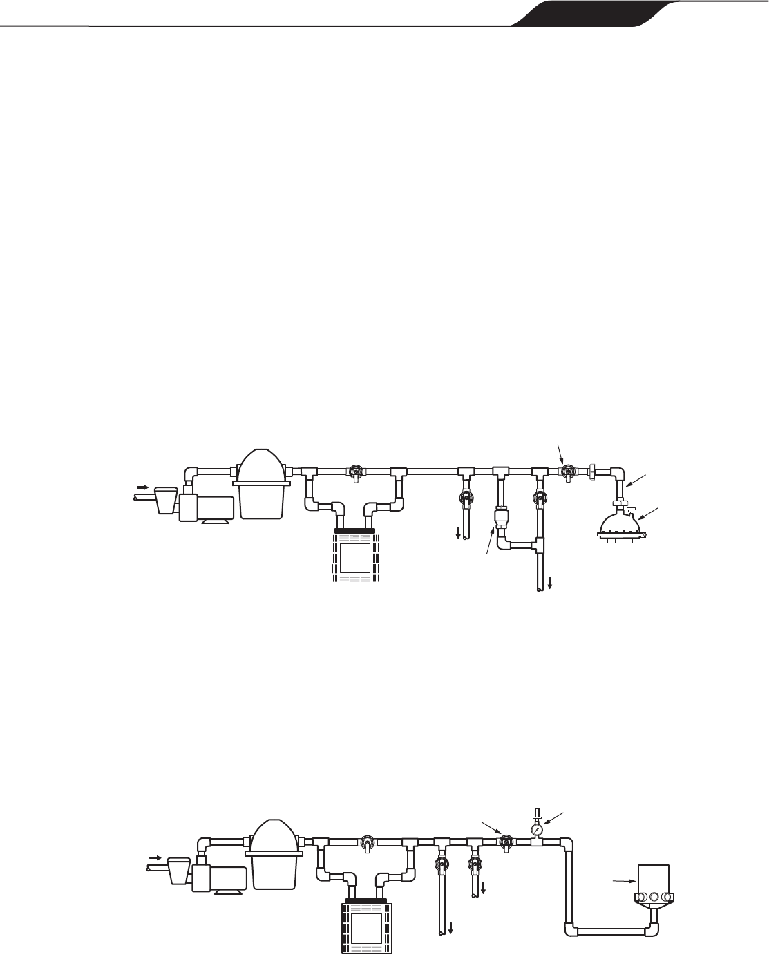
Valves
Install the non-functioning test housing (5-Port Test Housing, part #4-9-2002 purchased
separately) for setup and pressure testing during the construction phase. The functional
valve is installed at startup.
5-Port:
Plumb the pressure relief valve in a bypass line off the pool return line. Use two 2-way valves
(one on return line, one on valve feed line) to control flow. Use the 2 in. unions included to
install a removable section of pipe immediately before the valve to provide service access to
the valve cup screen.
The bottom plate of the valve is made of a hard fiberglass filler and must be primed heavily
before gluing. Connect the water source from the pool pump to the valve inlet.
Position the large o-ring in the bottom plate, align the guide pin and use the V-clamp to
attach the plate to the test housing. Tighten the V-clamp until ends are about ¾ in. apart.
UltraFlex 8-Port:
Plumb the pressure switch/gauge into the valve supply line at the pool equipment to ensure
flow to the valve. Install a 2-way valve in the line to simplify valve maintenance.
Connect the water source from the pool pump to the valve inlet. Do not get glue in the valve
housing as this will void the warranty. Tip: Do not turn valve upside down when gluing.
The valve is shipped with the top plate and removable pressure test plug pre-assembled and
secured to factory torques. Do not loosen or remove these items prior to pressure testing.
From
Pool
Filter
Pump
Heater
5-Port
Valve
To
Pool
Pressure
Relief Valve
Removable
Pipe Section
To Auxiliary
Equipment
2-Way
Valve
From
Pool
Filter
Pump
To
Pool
Heater
Pressure
Switch/Gauge
8-Port
Valve
To Auxiliary
Equipment
2-Way
Valve

Page 6
ENGLISH
Zodiac
®
Caretaker
TM
In-Floor Pool Cleaning System
|
Installation and Maintenance Guide
Discharge Lines
The 5-Port valve uses 1 ½ in. pipe to conserve space. Use 2 in. reducer 90’s to convert
pipe rather than reducer bushings. Use a 3 in. stagger when cutting pipes to provide enough
clearance for the reducers.
Connect PVC fittings directly to the 2 in. nipples on the UltraFlex
®
8-Port valve. If Backer
Rod (polyethylene foam) will be used to winterize the valve, 2 in. Sch. 40 tee fittings must
be plumbed off each of the (8) outlet lines instead of 90˚ ell fittings. Glue a 2 in. female fitting
adapter (spigot x female pipe thread) into the top outlet of the tee fitting and thread a 2 in.
plug (male pipe thread) into the top of the tee. Extend the discharge lines down at least 24 in.
below the freeze line.
Install the discharge lines from the valve in a stacked or flat configuration.
• Use heavy bodied PVC glue to connect PVC fittings to the valve housing. Do not get glue
inside the housing as it will void the warranty.
• Install all lines with a minimum of 6 in. cover or in accordance with local codes.
• The distribution system is designed to rotate from shallow to deep. Port 1 will always be
the step or bench port, followed by the shallow bank, etc. Looking down on the valve, it
rotates clockwise. If a spa is included in the application, it will require a dedicated line
from the valve. Follow the design plan to install the lines in the correct order.
• If all outlet ports on the valve are not needed, it is necessary to tie the unused port into
an active port or double port the line. Customarily, double port lines to the hardest-to-
clean area.
Consult the design plan for proper
connections.
5-Port - When plumbing the valve, skip a
port (ie. tie port #1 to port #3, not #2) when
double porting.
UltraFlex 8-Port - Install a service-accessible
check valve on both outlet ports to prevent
reverse water flow. Skipping is unnecessary.
Check Valve
8-Port Valve
8-Port Valve
Stacked
5-Port Valve
Flat

Page 7
ENGLISH
Installation and Maintenance Guide
|
Zodiac
®
Caretaker
TM
In-Floor Pool Cleaning System
Auxiliary Equipment
Heaters
To compensate for heater system pressure drops, plumb heaters in a bypass line before the
water valve. The heater bypass valve should be adjusted to ¾ open.
Chlorinators
In-floor systems can be used with erosion feeders, ozone generators and in-line salt
converters. Consult manufactures instructions for proper installation to protect water valve
and other pool equipment.
Automatic Pool Cleaners
When supplementing the in-floor system with a Zodiac automatic pool cleaner, plumb the
dedicated cleaner line (booster pump if applicable) before the valve.
Pressure Testing
Pressure-test the system at a minimum of 35 psi or local code requirements. Keep the water
valve secure and under pressure throughout the construction process.
Burial Cable for Electrical Hook-up of Controller (UltraFlex 8-Port only)
Since there is an open plumbing trench from the equipment to the water valve location, it is
most convenient to complete the cable installation during the plumbing phase.
The electrical line from the controller to the valve must be the 18-gauge Burial Cable (part
#1-9-182) as this cable has specific rating and certification for this product. For cable runs
(i.e. electrical cable between controller and valve) in excess of 80 feet, contact Zodiac before
wiring.
1. Reference Table 300 of the National Electric Code (NEC) for minimum burial
depth requirements.
2. Leave excess wire (approximately 5 feet) at both the controller location and the
valve location.
When all connections are complete and it is clear the system is holding pressure, backfill,
tamp and level all trenches.
From
Pool
Filter
Pump
Heater
5-Port
Valve
To Chlorinator
To Cleaner
To Pool

Page 8
ENGLISH
Zodiac
®
Caretaker
TM
In-Floor Pool Cleaning System
|
Installation and Maintenance Guide
Installing Electrical Connections (UltraFlex 8-Port only)
Disconnect power supply before making any electrical connections. Refer to the wiring
diagram (also located inside the controller) for complete details on all connections.
UltraFlex Controller
The controller can be connected to either a 120V or 240V power source, and hardwired or
connected, using the appropriate plug, to a standard outlet protected with an approved cover.
• Mount controller on wall or vertical surface near the pool equipment
• Install flexible conduit to house the wiring
• Use no less than 12-gauge wire to make connections
• Use proper connectors and wire nuts to connect the transformer
Pressure Switch Connection
Connect the pressure switch, plumbed into the supply line, to the controller.
• Install flexible conduit to house the wiring
• Use no less than 18-gauge wire to make connection
• Use 18-22 gauge, fully insulated male push-on connectors at the switch
• Connect the pressure switch leads to the top terminal strip on the controller PCB
Valve Connection
If the plumber did not do the burial cable installation:
• The electrical line from the controller to the valve must be the 18-Gauge Burial Cable
(part #1-9-182) as this cable has specific rating and certification for this product. For
cable runs in excess of 80 feet, contact Zodiac for cable specifications
before wiring.
• Reference NEC Table 300 for minimum burial depth requirements
• Connect the burial cable to the terminal strip on the motor mount plate at the valve,
and to the bottom terminal strip on the PCB in the controller. Verify that the wire color
sequence is the same at both locations.
24 VAC Secondary
240 VAC Primary
Main
PCB
Transformer
(24VAC Output)
Power Pressure Switch
(Green Terminal Bar)
To Va l v e
(Black Terminal Bar)
1 2 3 4
5 4 3 2 1
Fuse Reset
240 VAC
Power
Connectors
Pressure
Switch
To Main PCB
Control Knob
LED
Light
Blue
Blue/White
Ground
Screw
Controller (Side View)
Pressure Switch
(Side View)
Motor Mount
with Sensor Plate
(Top View)
Sensor Plate
Assembly
Black
White
Red
Brown
Green
Black
White
Red
Brown
Green
Motor
Connect to
240 VAC Power
Brown
Brown
Black
White
Red
120 VAC Power
Wire
Nuts
Blac
k
White
B
lk
/Wht
W
hite / with
B
lk S
t
ripe
Black
Blk/Wht
White
W
hi
te / with
B
lk St
ripe
Connect to
120 VAC Power
3

Page 9
ENGLISH
Installation and Maintenance Guide
|
Zodiac
®
Caretaker
TM
In-Floor Pool Cleaning System
Preparing the System
Cut Cleaning Head Stub-ups and Clear Debris from System
After inspection, clear the system lines of debris using a combination of air and water.
1. Verify that the system is holding pressure (minimum of 35 psi), then relieve
system pressure.
2. Use the UltraFlex
®
Collar Template (part #1-17-7) to cut each stub-up ensuring collars sit
at a height to accommodate approximately ½ in. of final finish material.
Use a sander/grinder to sand each stub-up smooth and level with the shell finish to
ensure proper glue adhesion with collar setting. Insert test plug in each stub up.
3. UltraFlex 8-Port only: Remove the screws securing
the top plate and separate it from the valve. Attach the
UltraFlex Blower Plate (part # 4-7-305) to valve housing.
4. Attach a blower assembly unit (blower, check valve, air/
water supply and connectors; call Zodiac for assembly
instructions) to the blower plate or directly to the union
at the top of the 5-Port valve.
5. Turn on blower and water supply to fill the lines.
6. Starting at the cleaning head farthest from the valve,
remove test plug and flush the pipe, blocking and
releasing pressure several times to ensure a clear line.
Replace test plug and repeat for each stub-up.
Install Cleaning Collars and Heads
When the pool interior is completely clean and ready
for the final finish application, remove the test plugs
to install the collars and cleaning heads. Reference
design plan to verify color and nozzle size.
1. Use heavy bodied PVC glue to secure the
cleaning collars. (Primer can be used on the
stub-ups but not the collars. Use glue on both.)
2. Push collar firmly onto pipe.
3. Insert cleaning heads into collars.
4. Put blue protective caps on heads.
4
Collar
Cleaning
Head
Protective
Cap
Check
Valve
Blower
Water
Supply
Blower
Plate
For Vinyl Liner Pools:
Set collar fittings before clearing lines.
1. Cut pipe stub-up flush with the pool floor. Then use an inside pipe cutter to cut it
again 1 7/8 in. lower than the floor level.
2. Use ABS to PVC glue to secure the collar fitting. (Primer can be used on the pipe but
not the fitting. Use glue on both.) Insert collar to a full stop to ensure proper height.
3. Excavate an area (12 in. around head and 8 in. below excavated floor) and fill with
concrete to form a “thrust block” to eliminate movement of the cleaning head.
4. Clear lines and insert test plugs limiting water use as there is no solid pool bottom.
Page 10
ENGLISH
Zodiac
®
Caretaker
TM
In-Floor Pool Cleaning System
|
Installation and Maintenance Guide
Install Functional 5-Port Valve
Remove the builder test housing and install the functional 5-Port valve.
1. Loosen V-clamp and union to remove the test housing.
2. Install the (5) small o-rings on the functional valve, wet them if necessary to help them
stick but do not lubricate. Check positioning of large o-ring in groove of bottom plate.
3. Align guide pin and re-install V-clamp, tightening until band ends are about ¾ in. apart.
4. Position dome strainer (cone-up) and reconnect valve at union.
Install Internal Components of UltraFlex 8-Port Valve
Install the tee assembly.
1. Remove the blower plate and make sure the housing is clear of debris.
2. Install the tee-assembly o-rings (shipped in lubricated bag) on the top of the tee and on
the tee’s inlet and outlet.
3. Place assembled tee in housing, securing tee at the inlet.
4. Insert the ½ in. Teflon
®
wear-bar into the slot on the side opposite the outlet.
5. Re-install o-ring and the top plate.
Install the motor assembly.
1. Remove the screws from the mounting stand-offs located on the top plate.
2. Insert the motor assembly onto the top plate and rotate until it engages with the tee
assembly. The motor assembly plate will be flush with the top plate stand-off.
3. Align the mounting holes with the mounting stand offs and secure the motor assembly
to the stand-offs.
The UltraFlex
®
8-Port valve operates with a photocell for indexing. The valve lid must
be in place for the valve to operate properly.
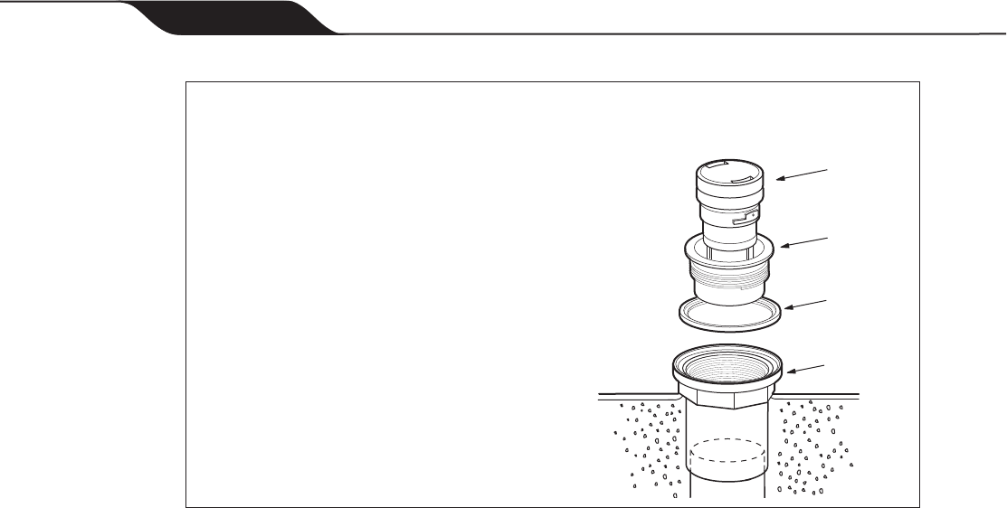
For Vinyl Liner Pools:
Pool liner must be in final position before installing collars and cleaning heads.
1. Press locking ring firmly into place in
groove on collar fitting. Installation Tip:
Turn collar upside down and use as a
tool to press ring into place.
2. Use a razor knife to cut liner inside the
locking ring, leaving at least a ¼ in. edge
around the ring perimeter.
3. Tighten the collar into the collar fitting,
turning clockwise until the collar lip fits
snugly against locking ring.
4. Insert Metal Combination Tool (part
#3-17-7) into collar and rotate clockwise
until collar is firmly seated.
5. Install cleaning head in collar.
Collar
Cleaning
Head
Locking
Ring
Collar
Fitting

Page 11
ENGLISH
Installation and Maintenance Guide
|
Zodiac
®
Caretaker
TM
In-Floor Pool Cleaning System
Starting the System
Before initiating the system, open a discharge line before the valve and flush the pool pump
and filtration system. Clear debris from all filters and screens.
1. Verify proper water pressure to valve, optimum level is 15-25 psi.
2. UltraFlex
®
8-Port Only: Check port
alignment. Verify that system has
discharge from only one valve outlet
at a time and that pressure drops
during valve rotation and increases
when rotation is complete.
If adjustment is necessary:
• Verify secure installation of
tee assembly.
• Loosen sensor plate screws,
rotate plate clockwise 1/8 in. and
retighten.
3. Confirm that all cleaning banks operate and that each head advances during pop-up
and retraction.
4. UltraFlex 8-Port Only: The valve provides six operational timer options. Use these to
increase coverage (leave valve in each zone for a longer period), increase rotation times
or even pause the system.
• Position 1: 15 seconds
• Position 2: 30 seconds
• Position 3: 45 seconds
• Position 4: 60 seconds
• Position 5: Pause mode
• Position 6: Programmable (adjustable from 3 - 60 seconds)
5
Sensor
Plate
1/8" Rotation
Screws

Page 12
ENGLISH
Zodiac
®
Caretaker
TM
In-Floor Pool Cleaning System
|
Installation and Maintenance Guide
The Zodiac Caretaker cleaning heads are designed to operate at a specific gallonage and
pressure. To maintain flow through the heads, run the system whenever the pump is on.
Cleaning times will vary according to application and environment. To determine the optimum
cleaning time, run the system 24 hours a day to start. Reduce run times by two hours every
two days until minimum cleaning time is determined. Six hours a day is recommended.
Cleaning the Filtration System
For optimum cleaning efficiency, routinely clean the pool pump basket, skimmer and
filter screens. The 5-Port valve dome strainer should be checked for debris and cleaned
periodically. Always reinstall the dome strainer in the cone-up position. Backwash the pool
filter whenever pressure increases 3 psi above normal clean-filter operating pressure.
Changing Cleaning Heads
The cleaning head must be in the full down position
before removal.
1. Attach the Head Removal Tool (part #3-17-7) to
the pool pole.
2. Snap tool into the head.
3. Turn counter-clockwise to release head from collar.
4. Pull and lift head out of collar.
To reinstall, simply insert head into collar and turn
clockwise to lock it into position.
Winterizing
To prevent freeze damage in cooler climates, remove water from the outlet discharge lines
above the freeze line and seal the valve.
5-Port
1. Remove water valve.
2. Remove any cleaning heads located above the freeze line (step or bench heads).
3. Use compressor or blower to blow water from discharge lines.
4. Place winterizing plug into collar.
5. Insert winterizing plugs into ports on bottom plate of valve.
UltraFlex 8-Port
There are three alternative methods to winterize the UltraFlex
®
valve:
Backer Rod Method: Uses (polyethylene foam) to winterize the valve and requires the
installation of tee fittings at each outlet line of the valve.
Expansion Plug with Blow-Through Valve Method: Uses Rubber Tapered
(Winterizing) Expansion Plugs with Blow-Thru Valves to seal system.
Standard Expansion Plug Method: Uses regular Rubber Tapered (Winterizing) Plugs
to seal the system.
Operation and Routine Maintenance
Head
Removal
Tool
Cleaning
Head
Collar

Page 13
ENGLISH
Installation and Maintenance Guide
|
Zodiac
®
Caretaker
TM
In-Floor Pool Cleaning System
Before winterizing, disconnect the power/sensor cable from the terminal strip at the valve.
1. Remove the motor assembly, separate it from the top plate and store it in dry, protected
location.
Expansion plug methods: Remove tee assembly and tee assembly o-rings. Place the
o-rings in a plastic bag, and store them with the motor assembly.
2. Lower the water level of the pool to below the tile level.
3. Seal the valve.
Backer Rod method: Remove the 2
in. plugs from the tee plumbed on the
(8) outlet lines of the valve. Place a
2 in. diameter section of Backer Rod
(polyethylene foam) into the outlet line
until it reaches the bottom of the plumbing
line. (The plumbing line must extend a
minimum of 24 in. below the freeze line.)
Cut the foam level with the top of the tee
fitting and thread the 2 in. Plug halfway
onto the fitting.
Expansion plug methods: Using an air
compressor/blower at the filter system, blow out the feed line to the valve.
Place a #11 winterizing plug into the inlet
line at the valve.
Expansion plug with blow thru
valves: Place # 9 ½ expansion plugs
w/ blow thru valves into each outlet
port inside the valve. Use an air
compressor with an air chuck at the
valve to blow out the outlet lines. Blow
each line until air can be seen coming
from the line in the pool/spa floor.
Standard expansion plug: Use an
air compressor or 2 ½ hp spa blower
with an adapter to blow out the outlet
lines at the valve until air can be seen
coming from the line in the pool/spa
floor. Place a # 9 ½ expansion plug
into the each outlet port.
4. If cleaning heads are located above the
freeze line (i.e. steps, benches, etc.)
remove the heads and seal the lines.
Backer Rod method: Push 1 ½ in. diameter foam into the collar until it reaches the
bottom of the plumbing line below the pool/spa. Place a # 10 ½ (2 in. Pipe) Rubber
Tapered Expansion (Winterizing) Plug into the collar.
Expansion plug methods: Use the air compressor to blow out the line and place a
#10 ½ expansion plug into the collar.
5. Reinstall the top plate and the valve cover (test housing cover if available) for the winter
season.
At spring startup, apply lubricant to the motor assembly drive shaft before inserting it into the
top plate receptacle.
Plug
Valve
Outlet
Te e
Pipe
A
A
Section A-A Cutaway View
UltraFlex Top View
UltraFlex Top View
Winterizing Plug
(Feed Line)
Winterizing Plug
w/Blow-Thru
(Outlet Line)
A
A
Winterizing Plug
(Feed Line)
Section A-A Cutaway View
Winterizing Plug
(Outlet Line)

Page 14
ENGLISH
Zodiac
®
Caretaker
TM
In-Floor Pool Cleaning System
|
Installation and Maintenance Guide
Troubleshooting
If the Zodiac Caretaker cleaning system
displays the following actions, adjustments
may be necessary to restore performance.
Refer to exploded parts diagram for
part references.
Action: Dirty spots appear.
Solution: 1. Clean the pool filter, pump
basket, skimmer baskets and
if 5-Port valve, the valve
dome strainer.
2. Make sure all auxiliary valves
(surface returns, waterfall, spa
overflow, etc.) are closed.
Action: Dirt is trapped between heads.
Solution: 1. Verify that the heads on
each side of dirt are pointed
in the same direction. Advance
a head, if necessary, using
the head removal tool to
ratchet the head up and down
until nozzle points in the
correct direction.
2. Increase the cleaning time.
If using the UltraFlex valve,
increase run-time to
60 seconds.
Action: Cleaning head advances, but is
not cleaning.
Solution: 1. Check for debris lodged in
the nozzle.
Remove the head from the
collar. Run the pump for two
full cycles on problem bank.
Recheck for particles in the
cleaning head nozzle and
re-insert the cleaning head.
Action: Cleaning head will not pop up
or does not go down.
Solution: 1. Remove the head. Inspect the
cleaning head and collar for
plaster remnants or debris.
2. With system running on the
problem bank and lightly
depress the problem head a
using telescoping pool pole.
Action: Pressure is lower than normal.
Solution: 1. Clean the pool filter, pump
basket, skimmer baskets
and if 5-Port valve, the valve
dome strainer. Backwash the
pool filter.
2. Make sure all auxiliary valves
(surface returns, waterfall, spa
overflow, etc.) are closed.
3. Confirm that the pool pump is
operating normally.
4. Check for leaking or worn
o-rings. Replace if necessary.
Action: The 5-Port valve does not cycle.
Solution: 1. Clean the pool filter, pump
basket, skimmer baskets
and valve dome strainer.
Backwash pool filter if
necessary.
2. Make sure all auxiliary valves
(surface returns, waterfall, spa
overflow, etc.) are closed.
3. Turn pump on and off several
times to clear system.
4. Remove valve, turn upside
down, and spray pressurized
water up into the valve.

Page 15
ENGLISH
Installation and Maintenance Guide
|
Zodiac
®
Caretaker
TM
In-Floor Pool Cleaning System
Action: The UltraFlex valve does
not cycle.
Solution: 1. Make sure water is properly
routed to the valve; all auxiliary
valves (surface returns,
waterfall, spa overflow, etc.)
should be closed.
2. Verify that the valve is not in
pause mode.
3. Make sure GFI is not tripped
and check the main power
source connections.
4. Check pressure switch
wiring connections.
5. Verify that terminal pin number
(ex: pin #1-5) and wire color
sequence match on both ends
of electrical connections.
6. If the red indicator LED
remains on but the valve is
not rotating, check under
the top plate for mechanical
restrictions like debris or a
damaged o-ring.
Action: Two of the UltraFlex ports
are discharging water at the
same time.
Solution: 1. Check for proper port
alignment at the valve.
Action: UltraFlex valve does not pause
at an outlet port.
1. Verify that valve cover is
properly in place.
2. Replace defective or damaged
sensor (part #3-7-6).
Action: UltraFlex valve is leaking.
1. Check for debris underneath
the top plate (#4) or around the
face seal o-ring (#5) and clean
as necessary.
2. Verify that top plate is
tight. Replace the o-ring
if necessary.
3. Shaft seal is leaking, replace.
To replace the 5-Port water valve:
1. Unscrew the two union nuts and remove
the pipe section located in front of the
water valve.
2. Use a 7/16 in. deep socket with a ratchet
or a 7/16 in. wrench to loosen and
remove the V-clamp.
3. Lift water valve straight up to remove.
4. Remove the five small o-rings, the large
o-ring, the union o-ring, and the dome
strainer. If the system is over one year
old, replace the o-rings (O-Ring Kit,
part #5-13-1).
5. Place the five small o-rings on the
bottom of the replacement valve. Wet
them to help them stick; do no
use lubricants.
6. Place the large o-ring in the groove
provided in the bottom plate.
7. Locate the alignment pin and align it with
the hole on the bottom plate.
8. Place the V-clamp around the valve
and tighten (tap perimeter periodically
to ensure equal tension) until the band
ends are about ¾ in. apart.
9. Reinstall the dome strainer, dome up.
Replace connecting pipe section and
tighten unions securely.
10. Turn on system and check for leaks.

Page 16
ENGLISH
Zodiac
®
Caretaker
TM
In-Floor Pool Cleaning System
|
Installation and Maintenance Guide
2
1
1
4
1
33
33
3
5
1
1
6
7
8
10
9
Union O-Ring
Large O-Ring
Small O-Rings
Alignment Hole
Alignment Pin
Exploded Parts Diagram
5-Port Valve
No. Part # Description Qty
1 5-13-1 O-Ring Kit 1
2 1-1-216 Stainless Steel Dome Strainer 1
3 3-9-201 Top Housing 1
4 1-3-1 Pressure Gauge 1
5 5-9-2001 Rebuild Kit 1
6 1-9-214 Valve Center Plate 1
7 3-9-216 V-Clamp with Nut 1
8 1-9-215 Bottom Plate 1
9 1-1-220 Pressure Relief Valve 1
10 4-1-2002 Union Complete 2
Page 17
ENGLISH
Installation and Maintenance Guide
|
Zodiac
®
Caretaker
TM
In-Floor Pool Cleaning System
1
7
10
6
3
4
9
5
C
a
r
e
ta
k
e
r
S
ys
t
e
m
s
,
I
n
c
.
U
LT
RA
FL
EX
U
LT R A F
L E X
E
L
E
C
TRICA
L
RA
TI
N
G
S
I
n
pu
t
:
1
1
5
V
A
C
,
6
5
0
m
A
,
5
0
/
6
0
H
z
;
2
3
0
V
A
C
,
3
2
5
m
A
,
5
0
/
6
0
H
z
.
O
u
t
p
u
t
:
2
4
V
A
C
,
3
A
,
5
0
/
6
0
H
z
.
I
P
N
U
M
B
E
R
:
I
PX
4
C
A
U
T
I
O
N
:
RI
S
K
O
F
E
L
E
C
T
RI
C
A
L
S
H
O
C
K
K
E
E
P
C
O
V
E
R
O
N
E
N
C
L
O
S
U
R
E
T
O
PR
E
V
E
N
T
W
A
T
E
R
D
A
M
A
G
E
M
U
S
T
B
E
I
NS
T
A
L
L
ED
A
T
L
E
A
S
T
F
I
V
E
F
EE
T
FR
O
M
T
H
E
W
A
T
ER
’
S
ED
GE
s
e
c
on
ds
s
ec
ond
s
sec
onds
se
co
n
d
s
p
a
u
s
e
p
r
o
g
ra
m
60
45
0
5
8
11
2
12
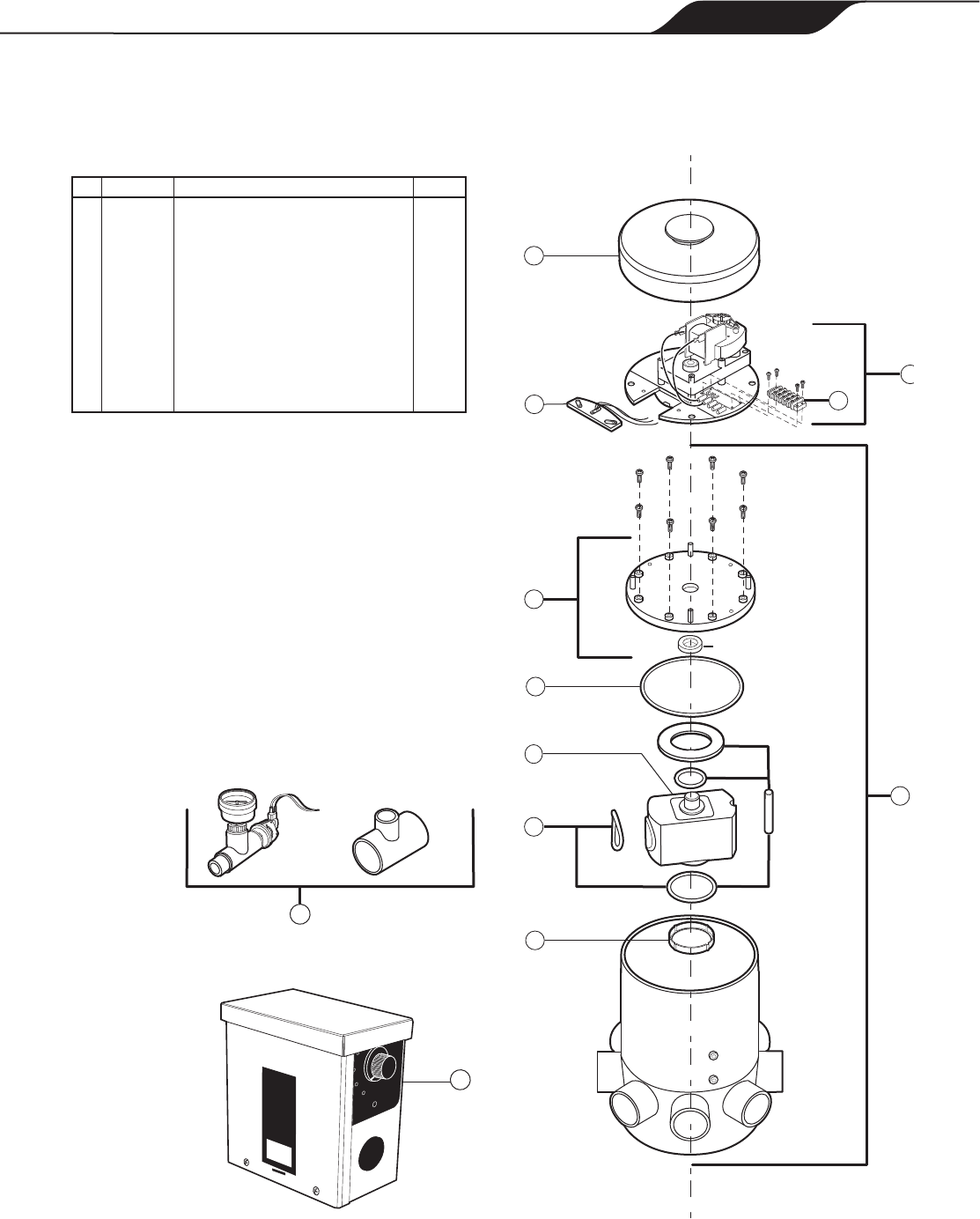
Exploded Parts Diagram
UltraFlex 8-Port Valve
No. Part # Description Qty
1 3-7-8 Valve Lid 1
2 3-7-5 Motor Assembly 1
3 3-7-6 Sensor Plate 1
4 3-7-12 Top Plate Assembly 1
5 1-13-15 O-Ring, Face Seal 1
6 3-7-3 Tee Assembly 1
7 4-7-4 O-Ring Kit 1
8 2-7-53 Inlet Wear Insert 1
9 4-7-2 Pressure Switch/Gauge Assembly 1
10 4-7-200 Plumbing Kit 1
11 4-7-202 Controller 1
12 4-9-189 Motor/Sensor Terminal Strip 1
Shaft Seal

Page 18
ENGLISH
Zodiac
®
Caretaker
TM
In-Floor Pool Cleaning System
|
Installation and Maintenance Guide
Notes

Page 19
ENGLISH
Installation and Maintenance Guide
|
Zodiac
®
Caretaker
TM
In-Floor Pool Cleaning System
Notes

Zodiac Pool Systems, Inc.
2620 Commerce Way, Vista, CA 92081
1.800.822.7933 | www.ZodiacPoolSystems.com
ZODIAC
®
is a registered trademark of Zodiac International, S.A.S.U., used under license.
All trademarks referenced herein are the property of their respective owners.
©2011 Zodiac Pool Systems, Inc. TL-1300 Rev. A 1103
