REPLACEMENT
Watkins Manufacturing Corporation
Of your Eagle Control Box 60Hz Utopia and Paradise 2012 - Current
PN 62843C (1/20)
Step 1. Disconnect power to the spa and access the equipment compartment.
Step 2. On the front of the control box, remove the screws and open the control box cover.
Step 3. On the left side of the control box, disconnect the copper bonding wires from the bonding lug.
Step 4. Mark and disconnect power wires from terminal block TB-1, remove the strain reliefs and conduit if necessary.
Step 5. On the top right side of the control box, disconnect the two thermistors from the thermistor inputs and the
pressure switch from its input.
Step 6. On the right side, disconnect the cable for the main panel and the cord for the auxiliary panel, if applicable.
Step 7. Along the bottom of the control box, identify and mark all wires for the components from the ag terminals and
disconnect them. Save the strain reliefs (if undamaged).
Step 8. Inside the control box, remove the mounting screws and slide the control box to the right.
Step 9. Lift the control box away from the bracket and remove.
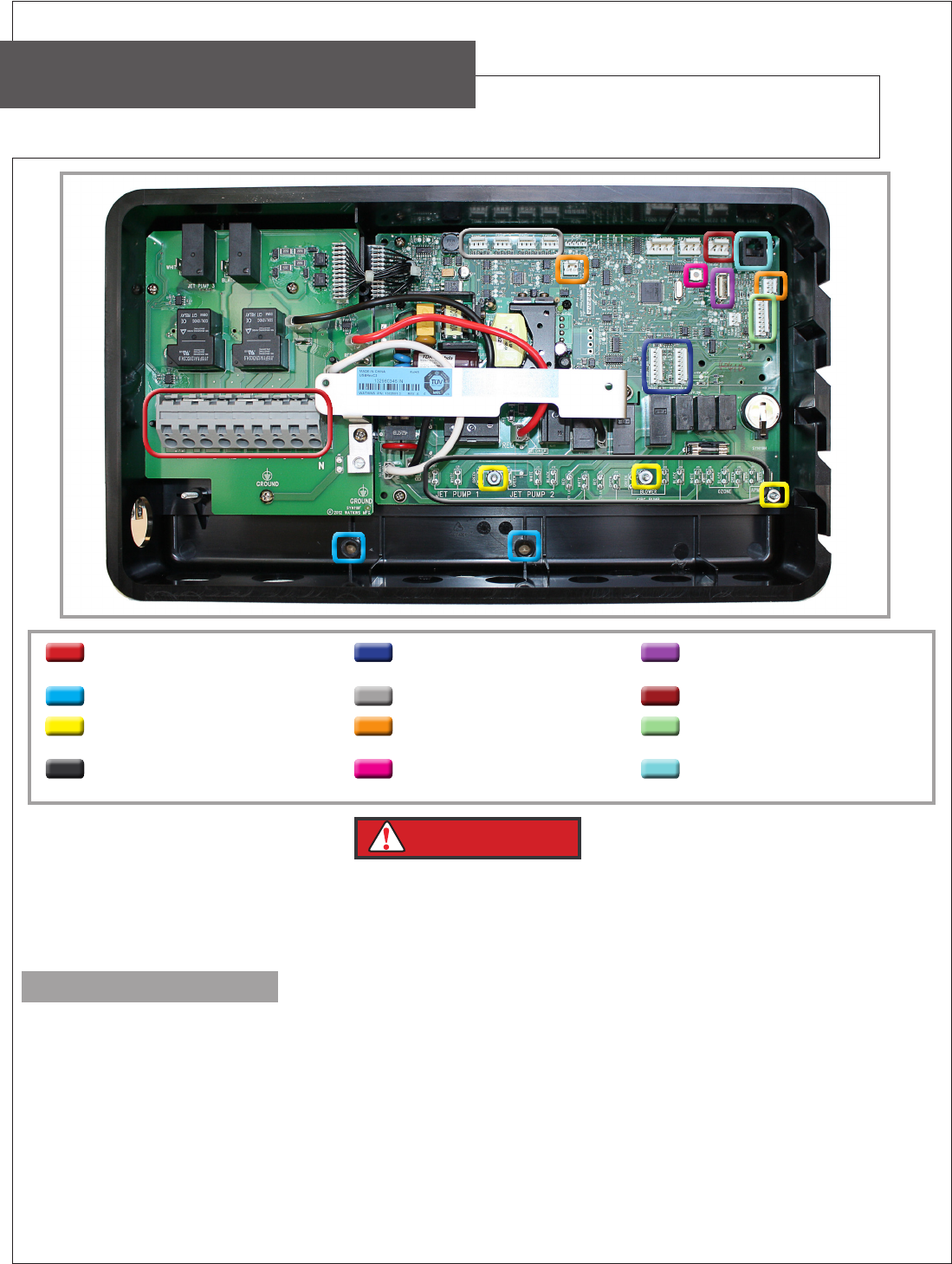
Control Box Removal
TERMINAL BLOCK PERIPHERAL INTERFACE
COMMUNICATION
USB PROGRAMMING PORT
MOUNTING SCREWS ZONE LIGHTING PRESSURE SWITCH
GROUNDING LUGS CONTROL AND HI-LIMIT
THERMISTOR
CONTROL PANEL
POWER CONNECTIONS FOR
COMPONENTS
SERVICE SWITCH AUX PANEL
IMPORTANT
The replacement Eagle Control Box must be updated to the current software version via the USB port
(using a formatted USB drive) and the software jumpers must be congured according to spa model via
control panel. Refer to the Control Box Software section in CDR portal to download the current software
version, Jumper Conguration Instructions and How to Format USB Drive Instructions.
Page 1
Control Box Installation
1. There are two rectangular tabs on the top of the control box. Align these tabs to the rectangular holes located at
the top of the bracket.
2. Insert the tabs into the holes and slide the control box to the left to lock it into place. Be sure that both tabs are
engaged.
3. Inside the control box, install the mounting screws to fasten the control box to the bracket
4. On the left side insert the heater power cord through the access hole and connect the black wire to H-1, the white
power wire to H-2 of the TB-1 terminal and the green ground wire from the heater to the heater ground terminal (just
below and center of TB-1 terminal block).
5. On the top right side of the control box, connect the two thermistors and the pressure switch input.
6. On the right side, connect the ribbon cable for the main panel and the cord for the auxiliary panel, if applicable.
7. Along the bottom of the control box, connect all components back to original ag terminals.
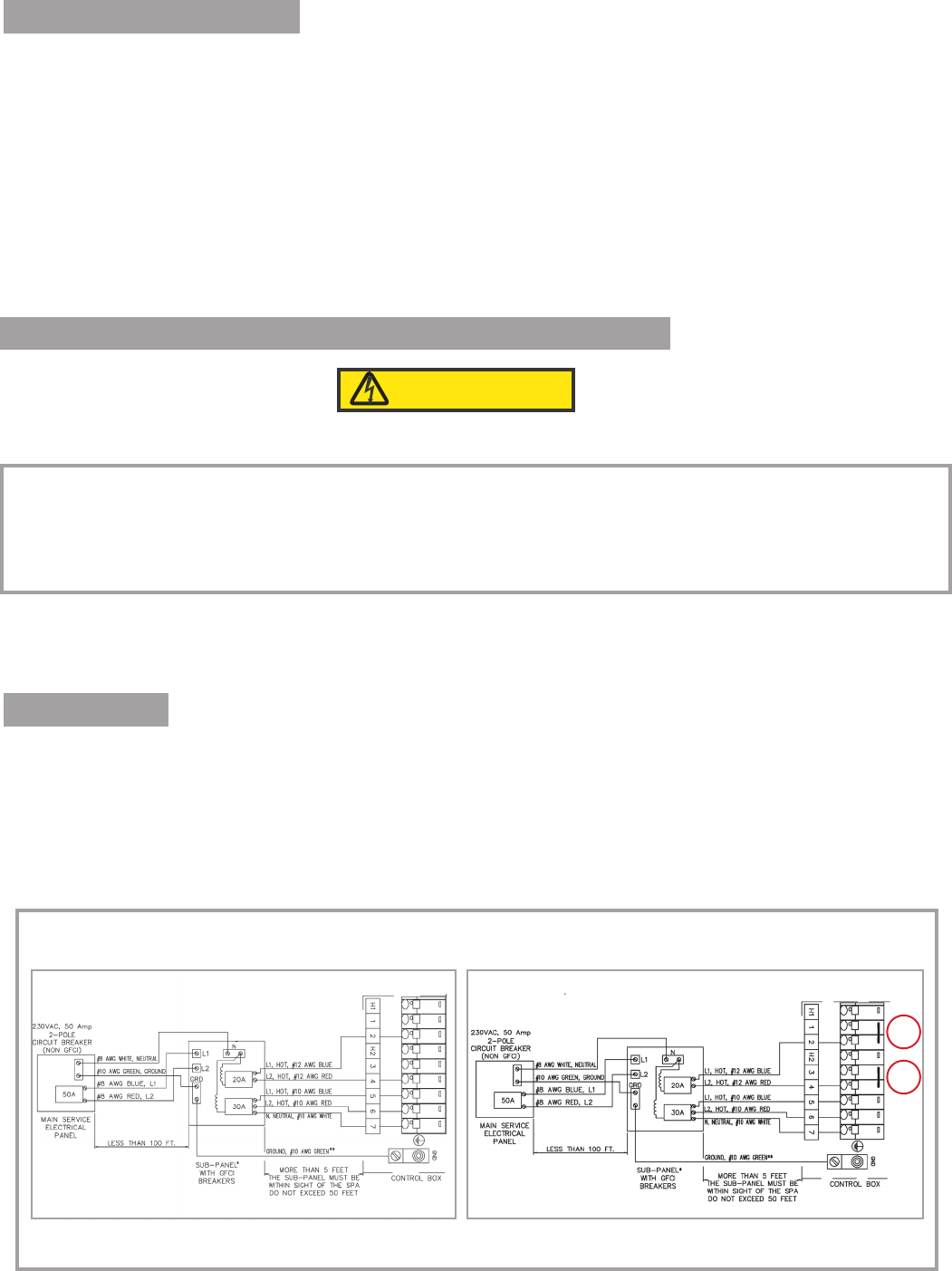
Wiring the Line Voltage Conduit to Terminal Block TB-1
CAUTION
If the line voltage is wired incorrectly, damage to the control box may occur.
ELECTRICAL REQUIREMENTS
ALL SPAS MUST BE WIRED IN ACCORDANCE WITH ALL APPLICABLE NATIONAL AND LOCAL ELECTRICAL
CODES. ALL ELECTRICAL WORK SHOULD BE DONE BY AN EXPERIENCED, LICENSED ELECTRICIAN. WE
RECOMMEND THE USE OF APPROPRIATE ELECTRICAL CONDUIT, FITTINGS, AND WIRE FOR ALL CIRCUITS.
1. The wiring instructions are located below.
2. Refer to the illustrations at the bottom of the page and locate the spa model and operating voltage.
3. Wire the terminal block (TB-1) as shown: Figures 1 - 3
Input Wiring
1. Connect the Blue (Hot) wire from the sub panel 20 amp breaker terminal L1 to TB-1, terminal 2.
2. Connect the Red (Hot) wire from the sub panel 20 amp breaker terminal L2 to TB-1, terminal 4.
3. Connect the Blue (Hot) wire from the sub panel 30 amp breaker terminal L1 to TB-1, terminal 5.
4. Connect the Red (Hot) wire from the sub panel 30 amp breaker terminal L2 to TB-1, terminal 6.
5. Connect the White (Neutral) wire from the sub panel 30 amp breaker terminal N to TB-1, terminal 7.
6. Connect the Green (Ground) wire from the sub panel ground bar to the source grounding lug.
7. CANTABRIA ONLY - Verify power jumpers (A) are set across terminals 1-2 and 3-4 on TB-1 Figure 2.
Figure 1 Figure 2
CANTABRIA
GENEVA • NIAGARA • TAHITIAN • SALINA
KAUAI • MARTINIQUE • MAKENA
A
A
Page 2

Input Wiring - Cantabria Converted Model
Figure 3
1. Connect the Blue (Hot) wire from the sub panel 20 amp breaker terminal L1 to TB-1, terminal 1.
2. Connect the Red (Hot) wire from the sub panel 20 amp breaker terminal L2 to TB-1, terminal 3.
3. Connect the Blue (Hot) wire from the sub panel 20 amp breaker terminal L1 to TB-1, terminal 2.
4. Connect the Red (Hot) wire from the sub panel 20 amp breaker terminal L2 to TB-1, terminal 4.
5. Connect the Blue (Hot) wire from the sub panel 30 amp breaker terminal L1 to TB-1, terminal 5.
6. Connect the Red (Hot) wire from the sub panel 30 amp breaker terminal L2 to TB-1, terminal 6.
7. Connect the White (Neutral) wire from the sub panel 30 amp breaker terminal N to TB-1, terminal 7.
8. Connect the Green (Ground) wire from the sub panel ground bar to the source grounding lug.
9. Remove the power jumpers (A) terminals 1-2 and 3-4 as shown on diagram Figure 2.
CANTABRIA CONVERTED
Page 3
