
AMD2000 Series D21xx Servo
Drive - User Guide
D-000088 Rev 06

AMD2000 Series D21xx Servo Drive - User Guide
ii D-000088 Rev 06 ANCA Motion
Page intentionally left blank

AMD2000 Series D21xx Servo Drive - User Guide
ANCA Motion D-000088 Rev 06 iii
AMD2000 Series D21xx Servo Drive
- User Guide
Some Important Links
Related User Guides and Brochures Related Documentation
Sales and Support Contact Information Product, Sales and Service Enquiries
For the latest copy of the user guide visit us online User Guides
For the latest version of the ANCA MotionBench
Software visit Software
Catalogue Number: DS619-0-00-0046
Document Reference: D-000088 Rev 06
Effective: 27-03-2017
© ANCA Motion Pty. Ltd.

AMD2000 Series D21xx Servo Drive - User Guide
iv D-000088 Rev 06 ANCA Motion
Page intentionally left blank

AMD2000 Series D21xx Servo Drive - User Guide
ANCA Motion D-000088 Rev 06 v
Chapter Summaries
1
Safety
General Product safety information
Introduction
Target Audience, model applicability, help in reading the
user guide and related user guides/brochures
2
3
4
Product Overview
Features, operating principles, labels, connector overview
Mechanical Installation
Requirements for site, tools, mounting, and cooling
5
Planning the Electrical Installation
Motor and drive compatibility, electrical isolation,
protection, cable selection and routing
6
Power Wiring
Insulation, earthing, power conditioning, brake connection
and regenerative brake
7
Control Wiring
Electrical Interfacing with the I/O connectors, EtherCAT and
motor feedback
8
Installation Checklist
Pre-power-up checks
9
Start-up
Refers to suite of configuration guides
11
Accessories
Selection of accessories including motors, cables, I/O
interface modules, filters, reactors, chokes magnetic cores
10
Technical Data
Functions, specifications, dimensions, de-rating, brake
resistor calculation, standards compliance
12
Additional Information
How to contact ANCA Motion with your enquiries

AMD2000 Series D21xx Servo Drive - User Guide
vi D-000088 Rev 06 ANCA Motion
Contents
1 Safety ................................................................................................................................................................. 1
1.1 General Safety ......................................................................................................................................... 1
1.2 Safe Start-Up and Operation ................................................................................................................... 2
2 Introduction ....................................................................................................................................................... 3
2.1 What this Chapter Contains ..................................................................................................................... 3
2.2 Purpose ................................................................................................................................................... 3
2.3 About the AMD2000 Series D21xx Servo Drives ..................................................................................... 3
2.4 Drive Model Applicability .......................................................................................................................... 3
2.5 Related Documents ................................................................................................................................. 4
2.6 Terms and Abbreviations ......................................................................................................................... 4
2.7 Trademarks ............................................................................................................................................. 4
3 Product Overview ............................................................................................................................................. 5
3.1 What this Chapter Contains ..................................................................................................................... 5
3.2 Features .................................................................................................................................................. 5
3.3 Operating Principle .................................................................................................................................. 6
3.4 AMD2000 Variant Identification ............................................................................................................... 6
3.4.1 AMD2000 Series Drive Catalogue Number Interpretation ......................................................... 7
3.5 System Overview ..................................................................................................................................... 8
3.6 Connector Overview .............................................................................................................................. 11
3.6.1 D2103 ...................................................................................................................................... 11
3.6.2 D2109 ...................................................................................................................................... 12
3.6.3 X1/X2 EtherCAT Connectors ................................................................................................... 12
3.6.4 X3 Serial Communications ....................................................................................................... 12
3.6.5 X4 Input / Output ...................................................................................................................... 13
3.6.6 X5 Encoder Interface ............................................................................................................... 13
3.6.7 Motor Armature Cable Connectors .......................................................................................... 13
3.6.8 Power, Inductor and Brake Resistor Connectors ..................................................................... 14
3.6.9 LED Display and Control Panel ................................................................................................ 14
4 Mechanical Installation ................................................................................................................................... 15
4.1 What this Chapter Contains ................................................................................................................... 15
4.2 Pre installation checks ........................................................................................................................... 15
4.3 Requirements ........................................................................................................................................ 15
4.3.1 Installation Site ......................................................................................................................... 15
4.3.2 Tools Required ......................................................................................................................... 16
4.3.3 Mounting and Cooling .............................................................................................................. 16
4.4 Installation ............................................................................................................................................. 17
4.4.1 Power Isolation ........................................................................................................................ 17
4.4.2 Mounting a Drive ...................................................................................................................... 18
4.4.3 Un-Mounting a Drive ................................................................................................................ 19
5 Planning the Electrical Installation ................................................................................................................ 20
5.1 What this Chapter Contains ................................................................................................................... 20

AMD2000 Series D21xx Servo Drive - User Guide
ANCA Motion D-000088 Rev 06 vii
5.2 Motor and Drive Compatibility ................................................................................................................ 20
5.3 Power Supply Disconnecting Device ..................................................................................................... 20
5.4 Emergency Stop Devices ...................................................................................................................... 20
5.5 Thermal Overload and Protection .......................................................................................................... 20
5.5.1 Fan Operation .......................................................................................................................... 20
5.5.2 Thermal Overload .................................................................................................................... 21
5.5.3 Motor Cable Short-circuit ......................................................................................................... 21
5.5.4 Supply Cable Short-circuit........................................................................................................ 21
5.5.5 Motor Thermal Protection......................................................................................................... 21
5.5.6 Brake Resistor ......................................................................................................................... 21
5.6 Power Cable Selection .......................................................................................................................... 21
5.7 Control Cable Selection ......................................................................................................................... 22
5.7.1 Motor Feedback Wiring ............................................................................................................ 22
5.7.2 EtherCAT Wiring ...................................................................................................................... 22
5.8 Cable Routing ........................................................................................................................................ 23
6 Power Wiring ................................................................................................................................................... 24
6.1 What this Chapter Contains ................................................................................................................... 24
6.2 Checking the Insulation of the Assembly ............................................................................................... 24
6.3 Mains Power Supply .............................................................................................................................. 24
6.3.1 AC Voltage Supply ................................................................................................................... 26
6.3.2 DC Voltage Supply ................................................................................................................... 27
6.3.3 Connection of drives to grounded systems (TN or TT) ............................................................ 27
6.3.4 Connection of drives to non-grounded systems (IT) ................................................................ 27
6.3.5 Harmonics and reactive power compensated supplies ............................................................ 27
6.3.6 Residual current-operated protective (RCD) protection ........................................................... 28
6.4 Grounding .............................................................................................................................................. 28
6.5 Installations conforming to the EMC Directive ....................................................................................... 29
6.5.1 For 3 phase supply system wiring ............................................................................................ 30
6.5.2 For 1 phase supply system wiring ............................................................................................ 31
6.5.3 Installation guidelines of EMC components ............................................................................. 32
6.6 Power Disconnect and Protection Devices ............................................................................................ 33
6.7 Motor Connections ................................................................................................................................ 34
6.7.1 Motor Circuit Contactors .......................................................................................................... 35
6.7.2 Motor Power Cable Installation ................................................................................................ 35
6.8 Drive Output Filters ................................................................................................................................ 41
6.8.1 Sinusoidal Filter ....................................................................................................................... 41
6.8.2 du/dt Filter ................................................................................................................................ 43
6.9 Motor Brake Connection ........................................................................................................................ 43
6.10 Motor Thermal Switch ............................................................................................................................ 44
6.11 Motor Thermal Sensor ........................................................................................................................... 44
6.12 Motor Thermal Estimation ...................................................................................................................... 45
6.13 Brake/Regeneration Resistor ................................................................................................................. 46
6.14 DC Busbar Terminals ............................................................................................................................ 46
7 Control Wiring ................................................................................................................................................. 48

AMD2000 Series D21xx Servo Drive - User Guide
viii D-000088 Rev 06 ANCA Motion
7.1 What this Chapter Contains ................................................................................................................... 48
7.2 Analogue I/O .......................................................................................................................................... 48
7.2.1 Analogue Inputs ....................................................................................................................... 48
7.2.2 Analogue Outputs .................................................................................................................... 50
7.3 Digital I/O ............................................................................................................................................... 51
7.3.1 24V Control Circuit Supply ....................................................................................................... 52
7.3.2 Digital Inputs ............................................................................................................................ 52
7.3.3 Digital Outputs ......................................................................................................................... 59
7.4 Safe Torque Off (STO) Operation .......................................................................................................... 60
7.4.1 Definitions ................................................................................................................................ 60
7.4.2 STO Overview .......................................................................................................................... 61
7.4.3 STO Considerations ................................................................................................................. 62
7.4.4 STO Operation ......................................................................................................................... 62
7.4.5 STO Wiring .............................................................................................................................. 64
7.4.6 Fault detection ......................................................................................................................... 68
7.4.7 STO Diagnostics ...................................................................................................................... 71
7.4.8 STO Function Commissioning Test Procedure ........................................................................ 71
7.5 Motor Brake Control............................................................................................................................... 76
7.6 Serial Communication Port .................................................................................................................... 76
7.7 Ethernet Interface .................................................................................................................................. 76
7.7.1 EtherCAT® .............................................................................................................................. 76
7.7.2 EtherCAT topology / Port assignment ...................................................................................... 76
7.8 DIP Buttons ........................................................................................................................................... 78
7.9 Motor Encoder Feedback ...................................................................................................................... 79
7.9.1 Analogue Encoder Interface..................................................................................................... 79
7.9.2 Analogue Encoder Cable ......................................................................................................... 80
7.9.3 Digital Encoder Interface .......................................................................................................... 80
7.9.4 Digital Encoder Cable .............................................................................................................. 81
7.9.5 Encoder Splitter Cable ............................................................................................................. 82
8 Installation Checklist ...................................................................................................................................... 83
8.1 What this Chapter Contains ................................................................................................................... 83
8.2 Checklist ................................................................................................................................................ 83
9 Start-up ............................................................................................................................................................ 85
10 Technical Data ................................................................................................................................................. 86
10.1 What this Chapter Contains ................................................................................................................... 86
10.2 Control Functions .................................................................................................................................. 86
10.2.1 Control Modes ..................................................................................................................... 86
10.2.2 Thermal and over-current protection.................................................................................... 86
10.2.3 Self-Protection features ....................................................................................................... 86
10.2.4 DC bus voltage control ........................................................................................................ 86
10.2.5 Advanced control functions .................................................................................................. 87
10.3 Interface Specifications .......................................................................................................................... 88
10.3.1 Digital I/O Supply ................................................................................................................. 88

AMD2000 Series D21xx Servo Drive - User Guide
ANCA Motion D-000088 Rev 06 ix
10.3.2 24V Digital Inputs ................................................................................................................ 88
10.3.3 24V Digital Outputs .............................................................................................................. 88
10.3.4 Differential Digital Inputs ...................................................................................................... 88
10.3.5 Differential Digital Encoder Output ...................................................................................... 89
10.3.6 Analogue Inputs ................................................................................................................... 89
10.3.7 Analogue Outputs ................................................................................................................ 89
10.3.8 Motor Position Feedback ..................................................................................................... 89
10.3.9 Encoder Channel 1 .............................................................................................................. 90
10.3.10 Encoder Channel 2 .............................................................................................................. 90
10.3.11 Encoder Supply ................................................................................................................... 90
10.3.12 Ethernet Interface ................................................................................................................ 90
10.3.13 Modbus Interface ................................................................................................................. 90
10.3.14 Drive Display ....................................................................................................................... 91
10.4 Electrical Specifications ......................................................................................................................... 91
10.4.1 Power supply section ........................................................................................................... 91
10.4.2 Digital servo drive ................................................................................................................ 91
10.4.3 Resolution ............................................................................................................................ 92
10.4.4 Steady State Performance ................................................................................................... 92
10.4.5 Regenerative Braking .......................................................................................................... 92
10.5 Environmental Specifications ................................................................................................................. 93
10.5.1 Storage ................................................................................................................................ 93
10.5.2 Transport ............................................................................................................................. 93
10.5.3 Installation and Operation .................................................................................................... 93
10.5.4 Physical Characteristics ....................................................................................................... 94
10.5.5 Cooling ................................................................................................................................ 94
10.6 Dimension Drawings .............................................................................................................................. 94
10.6.1 D2103 drive mounting hole positions and physical dimensions (mm) ................................. 94
10.6.2 D2109 drive mounting hole positions and physical dimensions (mm) ................................. 95
10.7 24V Control Circuit Supply ..................................................................................................................... 95
10.8 Voltage and Temperature De-rating ...................................................................................................... 96
10.8.1 D2103 De-rating .................................................................................................................. 96
10.8.2 D2109 De-rating ................................................................................................................ 100
10.9 Regeneration Resistor ......................................................................................................................... 103
10.9.1 Regeneration Resistor Selection, Regeneration Energy and Power ................................. 104
10.10 Materials .............................................................................................................................................. 105
10.11 Standards Conformity .......................................................................................................................... 106
Marking & Applicable Regulations .................................................................................................................. 106
Standard ......................................................................................................................................................... 106
Certification Organisation ................................................................................................................................ 106
10.11.1 CE Declaration of Conformity ............................................................................................ 107
10.11.2 EtherCAT® Conformance Marking .................................................................................... 109
11 Accessories ................................................................................................................................................... 110
11.1 What this Chapter Contains ................................................................................................................. 110
11.2 Motors .................................................................................................................................................. 110

AMD2000 Series D21xx Servo Drive - User Guide
x D-000088 Rev 06 ANCA Motion
11.2.1 Motor Catalogue Number Interpretation ............................................................................ 110
11.2.2 Motor Electrical Information Summary ............................................................................... 111
11.2.3 Brake Motor Specific Information ....................................................................................... 111
11.2.4 Motor Mechanical Information Summary ........................................................................... 112
11.3 Cables ................................................................................................................................................. 113
11.3.1 Cable Catalogue Number Interpretation ............................................................................ 113
11.3.2 Encoder Cables ................................................................................................................. 114
11.3.3 Armature Cables ................................................................................................................ 114
11.4 Other Accessories ............................................................................................................................... 116
11.4.1 I/O Interface Cable ............................................................................................................ 116
11.4.2 I/O Interface Module .......................................................................................................... 116
11.4.3 I/O Interface Module Kit ..................................................................................................... 116
11.4.4 I/O Connector .................................................................................................................... 117
11.4.5 D21xx STO Override Plug ................................................................................................. 117
11.4.6 EtherCAT Cables ............................................................................................................... 117
11.4.7 Armature Cable Shield Termination Kit.............................................................................. 118
11.4.8 EMI Filters ......................................................................................................................... 118
11.4.9 Line Reactors .................................................................................................................... 118
11.4.10 DC Chokes ........................................................................................................................ 118
11.5 Starter Kits ........................................................................................................................................... 119
11.5.1 D2103 SoE Starter Kit ....................................................................................................... 119
11.5.2 D2109 SoE Starter Kit ....................................................................................................... 119
11.5.3 D2103 CoE Starter Kit ....................................................................................................... 119
11.5.4 D2109 CoE Starter Kit ....................................................................................................... 120
12 Additional Information .................................................................................................................................. 121
12.1 What this Chapter Contains ................................................................................................................. 121
12.2 Maintenance and Repairs .................................................................................................................... 121
12.3 Product, Sales and Service Enquiries.................................................................................................. 121
12.4 Feedback ............................................................................................................................................. 121

Safety
ANCA Motion D-000088 Rev 06 1
1
1 Safety
Warning: To prevent possible accidents or injury, ensure you read and understand this user guide before
commencing installation or commissioning work on the AMD2000 drives.
DANGER HIGH VOLTAGE - The working DC bus is live at all times when power is on. The Main Isolator
feeding the drive must be switched to the off position at least 15 minutes before any work is commenced
on the unit. The operator must check the bus voltage with a tested working voltage measuring instrument
prior to disconnecting any connectors or opening the DC Bus terminal cover. The red LED indicator on the
front of the drive which indicates that there is charge remaining in the drive is only to be used as an aid to
visual troubleshooting. It should not be relied on as a means of safety.
Rotating permanent magnet motors can produce large voltages. Please ensure that the motors have
stopped rotating before commencing work.
This user guide and the warnings attached to the AMD2000 only highlight hazards that can be predicted by
ANCA Motion. Be aware they do not cover all possible hazards.
ANCA Motion shall not be responsible for any accidents caused by the misuse or abuse of the device by the
operator.
Safe operation of these devices is your own responsibility. By taking note of the safety precautions, tips and
warnings in this user guide you can help to ensure your own safety and the safety of those around you.
The AMD2000 is equipped with safety features to protect the operator and equipment. Never operate the
equipment if you are in doubt about how these safety features work.
1.1 General Safety
The following points must be understood and adhered to at all times:
Equipment operators must read the User Guide carefully and make sure of the correct
procedure before operating the AMD2000.
Memorize the locations of the power and drive isolator switches so that you can activate them
immediately at any time if required.
If two or more persons are working together, establish signals so that they can communicate to
confirm safety before proceeding to another step.
Always make sure there are no obstacles or people near the devices during installation and or
operation. Be aware of your environment and what is around you.
Take precautions to ensure that your clothing, hair or personal effects (such as jewellery) cannot
become entangled in the equipment.
Do not remove the covers to access the inside of the AMD2000 unless authorized
Do not turn on any of the equipment without all safety features in place and known to be
functioning correctly. Never remove any covers or guards unless instructed by the procedures
described in this user guide.
Never touch any exposed wiring, connections or fittings while the equipment is in operation.
Visually check all switches on the operator panel before operating them.
Do not apply any mechanical force to the AMD2000, which may cause malfunction or failure.
Before removing equipment covers, be sure to turn OFF the power supply at the isolator. (Refer
to 4.4.1 Power Isolation.) Never remove the equipment covers during operation.
Keep the vicinity of the AMD2000 clean and tidy.
Never attempt cleaning or inspection during machine operation.

AMD2000 Series D21xx Servo Drive - User Guide
2 D-000088 Rev 06 ANCA Motion
Only suitably qualified personnel should install, operate, repair and/or replace this equipment.
Be aware of the closest First Aid station.
Ensure all external wiring is clearly labelled. This will assist you and your colleagues in
identifying possible electrical safety hazards.
Clean or inspect the equipment only after isolating all power sources.
Use cables with the minimum cross sectional area as recommended or greater.
Install cables according to local legislation and regulations as applicable.
Insulation resistance testers (sometimes known as a ‘megger’ or hi-pot tester) are not to be used
on the drive, as a false resistance reading and/or damage to the drive may result
1.2 Safe Start-Up and Operation
Please refer to sections 8 Installation Checklist and section 9 Start-up for additional checks that should be made
to start up the AMD2000 series drives safely.

Introduction
ANCA Motion D-000088 Rev 06 3
2
2 Introduction
2.1 What this Chapter Contains
This chapter introduces reader to the user guide, the target audience and some useful information with regards to
comprehending the content.
2.2 Purpose
This user guide provides the required information for planning to install, installation and servicing of the AMD2000
Series Servo Drive. It has been written specifically to meet the needs of qualified engineers, tradespersons,
technicians and operators. This user guide does not cover configuration of the drive. Depending on the model of
drive purchased, please refer to the applicable Servo over EtherCAT
®
Configuration Guide or CANopen over
EtherCAT
®
Configuration Guide, for information on parameter configuration and tuning for your application.
Every effort has been made to simplify the procedures and processes applicable to the AMD2000 in this User
Guide. However, given the sometimes complex nature of the information, some prior knowledge of associated
units, their configuration and or programming has to be assumed.
2.3 About the AMD2000 Series D21xx Servo Drives
The AMD2000 Series D21xx Servo Drives are capable of motion control for applications that may vary from
precise control of movement and angular position of permanent magnet synchronous motors through to less
rigorous applications such as simple speed control of induction motors. In many of these applications the
rotational control of the motor is converted to motion using mechanical means such as ball screws and belts.
Both the D2103 and D2109 drives covered by this user guide incorporate a Safe Torque Off (STO) function,
allowing an external safety system to disable the PWM switching in the drive in a reliable and safe manner, and
consequently shutting down the delivery of torque to the driven machinery. This function is often used to replace
external safety contactors, thereby reducing the need to re-start power up sequences in machinery, and reducing
the total safety system costs for the end user.
Motion control is performed by the drive controller which accepts position feedback from motor encoders and/or
separate linear scales. The drive utilizes state-of-the-art current-regulated, pulse-width-modulated voltage-
source inverter technology that manages motor performance. In general, the Drive control receives motion
control commands via a higher level controller, which is based on an Ethernet-based field-bus interface. In
certain applications the drive is capable of executing pre-defined moves that are stored in local memory, without
the use of a motion controller. The AMD2000 drive also supports position, velocity and torque control modes.
Please refer to 3.2 Features for more details of features available
2.4 Drive Model Applicability
This user guide is applicable to the following variants of the ANCA Motion AMD2000 Series Servo Drives:
Product
Product variant
Product Number
AMD2000 Series Servo
Drive
3A RMS with STO
D2103
9A RMS with STO
D2109

AMD2000 Series D21xx Servo Drive - User Guide
4 D-000088 Rev 06 ANCA Motion
2.5 Related Documents
AMD2000 Series Servo Drive – CoE Configuration Guide
AMD2000 Series Servo Drive – SoE Configuration Guide
ANCA Motion MotionBench – User Guide
Digital Servo Drive CoE/SoE Parameter Reference – Included with firmware bundle
Digital Servo Drive Error Code Reference – Included with firmware bundle
2.6 Terms and Abbreviations
DSD
Digital Servo Drive
EMC
Electromagnetic Compatibility
IEC
International Electrotechnical Commission
I/O
Bidirectional Input / Output
O
Output
AIN
Analogue Input
AOUT
Analogue Output
DI
Digital Input
DO
Digital Output
W.R.T.
With Respect To
GND
Ground
RMS
root mean square
V / mV
Volt / millivolt
A / mA
Ampere / milliamp
Φ
Phase
Ø
Diameter
Ω
Ohms
AC / DC
Alternating Current / Direct Current
Hz
Hertz
ms
Millisecond
SoE
Servo Drive Profile according to IEC 61800-7-204 over EtherCAT
®
CoE
CAN Application Protocol over EtherCAT
®
CNC
Computer Numerical Control
DCM
Drive-Controlled Moves
PMSM
Permanent Magnet Servo Motor
PMAC
Permanent Magnet Alternating Current
STO
Safe Torque Off
PE
Protective Earth
PN panels
Part Number Panels
2.7 Trademarks
EtherCAT
®
is a registered trademark and patented technology, licensed by Beckhoff Automation GmbH,
Germany.

Product Overview
ANCA Motion D-000088 Rev 06 5
3
3 Product Overview
3.1 What this Chapter Contains
This chapter introduces reader to the D21xx servo drive by providing the following information
Features,
Operating Principle
Explanation of Labelling and Markings
Connector overview
3.2 Features
The D21xx is a versatile brushless AC servo drive incorporating a digital signal processor (DSP) for control of
rotary and linear motors. In general, the drive receives motion commands via a higher level controller, such as a
CNC, either in the form of structured position commands, or as a series of instructions controlling one or more
user pre-defined moves stored locally on the drive. The communication is based on the state-of-the-art
EtherCAT
®
interface. In certain applications the drive is also capable of running in standalone mode executing
pre-defined repetitive moves
Standard features include:
Single axis drive for AC synchronous servo motors and induction motors.
Models with continuous current ratings of 3A or 9A.
Direct connection to 100V – 240VAC single phase or 3-phase.
Support for incremental analogue and digital encoders.
Position, velocity and torque/current control.
Display and push buttons for standalone operation.
8 optically isolated general purpose digital inputs.
6 optically isolated general purpose digital outputs.
2 differential digital inputs (optionally can be used as additional general purpose digital inputs,
for a total of 10)
2 analogue inputs (±10V) and 2 analogue outputs (±10V).
Motor brake control.
Probe input for position latching.
Safe Torque Off (STO)
EtherCAT
®
connectivity.
Easy setup using ANCA MotionBench Tool.
Small foot print. On-board 24VDC power supply and auxiliary I/O reduce overall system size
and cost.
Rugged and reliable design
Please refer to section 10 Technical Data for detailed product specifications
AMD2000 Series D21xx Servo Drive - User Guide
6 D-000088 Rev 06 ANCA Motion
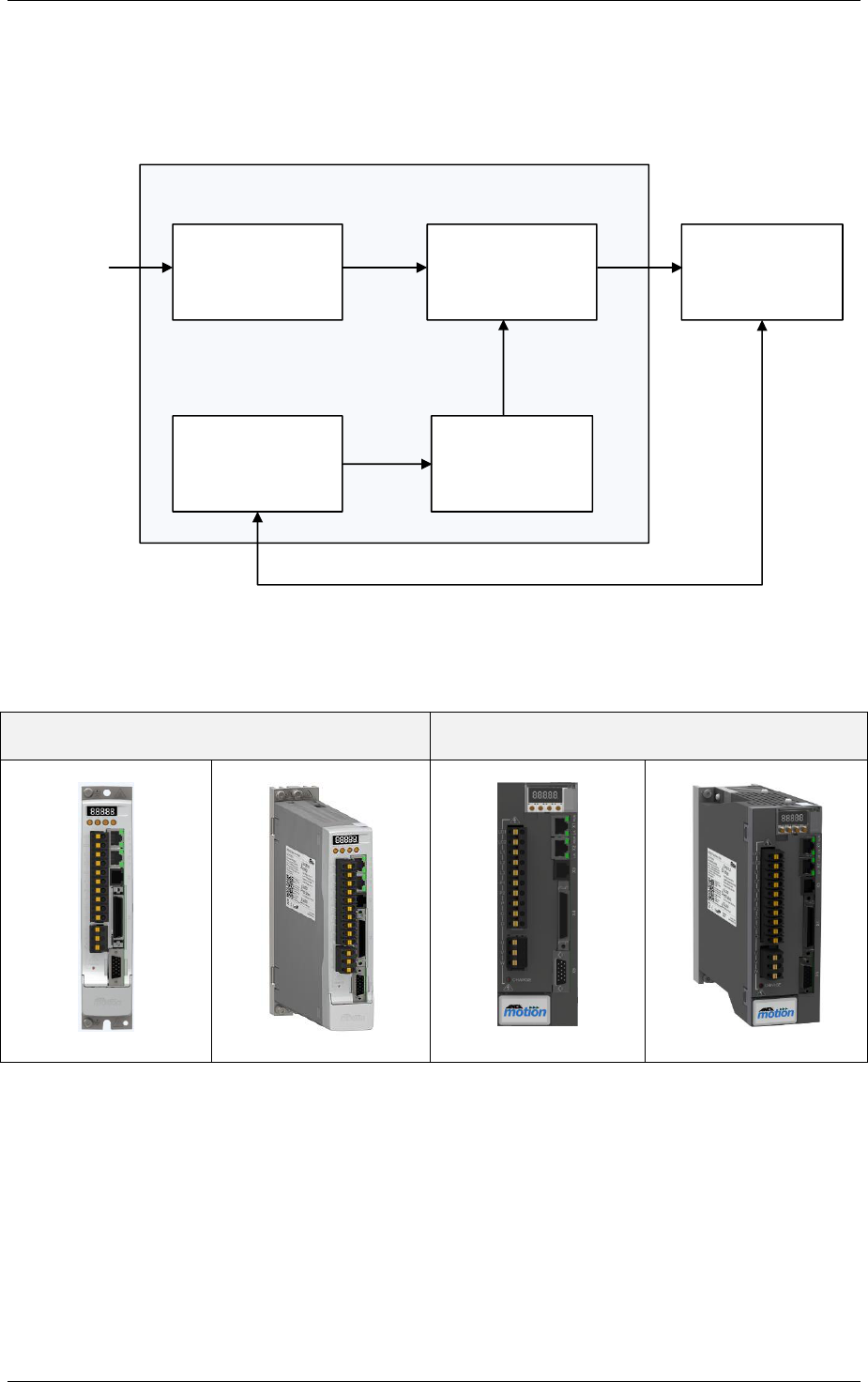
3.3 Operating Principle
The simplified circuit diagram of the drive is shown below. The AC supply voltage is converted to DC, which is
then converted into the required variable frequency AC voltage signal to drive the motor.
AC Motor
Drive Control
Switching
Control
Single or
3 Phase
AC Input
DC/AC ConverterAC/DC Converter
AMD2000 Servo Drive
3.4 AMD2000 Variant Identification
D2103
D2109

Product Overview
ANCA Motion D-000088 Rev 06 7
3
3.4.1 AMD2000 Series Drive Catalogue Number Interpretation
AMD2000 drives are marked with an identification label. The Catalogue number is explained as follows:
D2103-2S2-A
Product
D:Drive
2:AMD2000 Series
Current Rating
09 : 9 Amp
03 : 3 Amp
Feedback Type
1: Incremental Encoder (RS422)
2: Incremental Encoder (RS422 & 1Vpp)
Communications
S: Servo Profile over EtherCAT
C: CAN over EtherCAT
Rated Voltage
2: 100-240 VAC
Hardware Identification
A: Hardware Type A
Variant
0:Non-STO
1:STO
For any warranty work to be undertaken these labels must be readable and undamaged. Care should be taken to
record these numbers in a separate register in the event of damage or loss.
Note: Do not under any circumstances tamper with these labels. Your warranty may be void if the labels
are damaged.

AMD2000 Series D21xx Servo Drive - User Guide
8 D-000088 Rev 06 ANCA Motion
3.5 System Overview
A digital drive system comprises one or more digital servo drives as shown in the following Figure:
DRIVE 1 DRIVE N
M
Control Master
100-240VAC (3-0Φ)
Power Supply
100-240VAC (1-0Φ)
Power Supply
M
Analogue I/O
Digital I/O
Analogue I/O
Digital I/O
Figure 3-1 System Overview
Above example is of a drive system is supplied from a single or three phase mains connection with a nominal
voltage of 230VAC. Motion control commands are received from a control system, such as a CNC, either in the
form of structured position commands, or as a series of instructions controlling one or more user pre-defined
moves stored locally on the drive.
The following figure provides a block diagram of the drive system. There are two versions of drive system
available corresponding to maximum continuous motor current ratings of 3A and 9A. The EtherCAT
communications channel is routed between the components within the drive system and the external control
system via CAT5E or CAT6 Ethernet cabling. This communications channel provides interconnectivity for the
purpose of transmitting and receiving data, such as position commands.
Alternatively, each drive can be controlled through a combination of analogue and digital I/O. A number of
analogue inputs and digital inputs/outputs are provided in each drive for user defined signals which may be used
for application specific functions.

Product Overview
ANCA Motion D-000088 Rev 06 9
3
Controller
Communications
Interface
M
Analog Inputs
Analog Output
24V Digital
Inputs
Regeneration
Resistor
Servo Motor
Position
Encoder 1
Position
Encoder 2
Encoder
Output
Standard
Digital
Outputs
EtherCAT
Communications
Network
EtherCAT
Communications
Network
Soft Starting
PWM Control
Heatsink Temperature
Regeneration Resistor Control
100-240VAC
1Ø-3Ø Power
Supply
100-240VAC
1Ø Power
Supply
Inductor/ DC link
STO Control
STO Outputs
STO Inputs
Optional External
Regeneration Resistor
Figure 3-2 Block Diagram of the Drive System

AMD2000 Series D21xx Servo Drive - User Guide
10 D-000088 Rev 06 ANCA Motion
X1
X2
Servo Motor
Setup Software
Parameter configuration and monitoring is
possible via communication with a PC. X1 is
connected directly to the configuration PC rather
than the host device.
Host Device
EtherCAT Master capable device.
e.g. CNC or EtherCAT IN
X3
Brake Power
X5
X4
I/O Interface Module
EtherCAT OUT
Serial
Communications
Supply Earth
Optional External
Regenerative Resistor
Circuit Breaker
Cuts off power in the
case of an overload, to
protect the power line.
Noise Filter
Attached to prevent
external noise from the
power source line.
Figure 3-3 Connection Overview
Product Overview
ANCA Motion D-000088 Rev 06 11
3
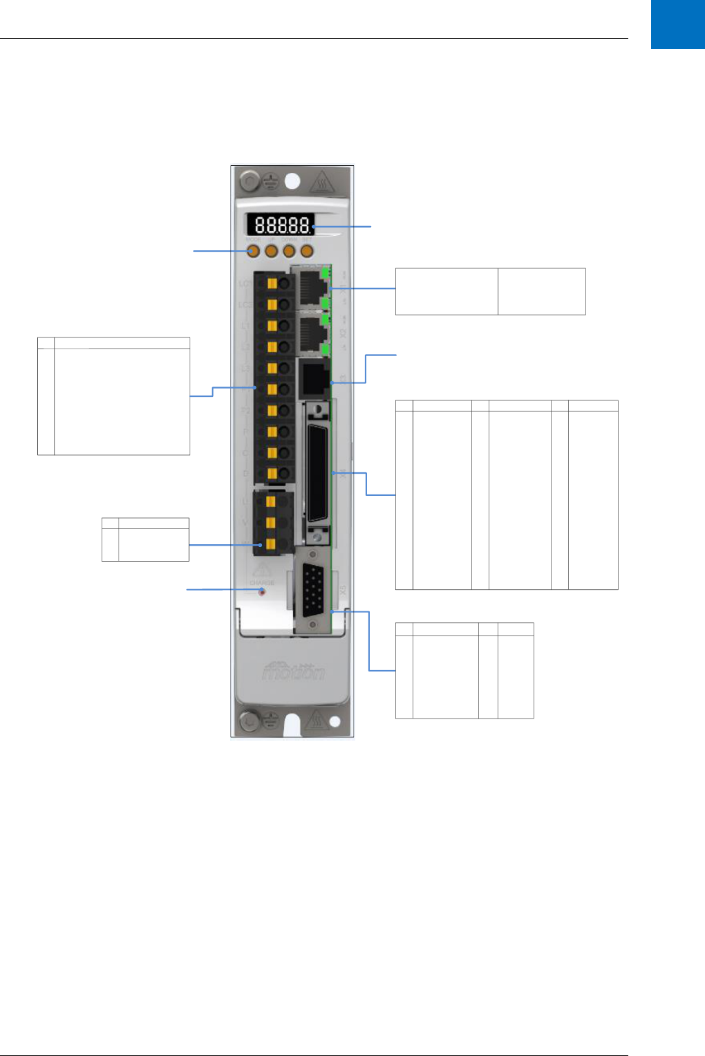
3.6 Connector Overview
3.6.1 D2103
7 Segment Display
Power Connection
Armature/Motor Connection
DC Bus Charge Indicator
1
2
3
4
5
6
7
8
PIN
SIN- / A-
SIN+ / A+
COS- / B-
COS+ / B+
Data- / Ref- / Z-
Data+ / Ref+/ Z+
A+
A-
SIGNAL
B+
B-
Z+
Z-
9VDC
5VDC
GND
PIN
SIGNAL
9
10
11
12
13
14
15
X5 Encoder Interface
X4 Input/Output
X3 Serial Communications
X1/X2 EtherCAT IN/OUT
Ethernet Interface Protocol:
Baud Rate:
Drive Profile Definition:
Connection:
EtherCAT
100 MB/s
SERCOS
Ethernet RJ-45
PIN
SIGNAL
U
V
W
Motor Connection
Motor Connection
Motor Connection
PIN SIGNAL
LC1
LC2
L1
L2
L3
P1
P2
P
C
D
Control Voltage Single Phase Supply
Control Voltage Single Phase Supply
Single/Three Phase Supply
Single/Three Phase Supply
Single/Three Phase Supply
External Inductor Connection
External Inductor Connection
Braking Resistor
Braking Resistor
Braking Resistor
1
2
3
4
5
6
7
8
9
10
11
12
13
14
15
16
17
PIN PIN
Al-01 +
Al-02 +
AGND
AGND
SFR-A
SFR-B
DI-01
DI-02
DI-03
DI-04
DI-05
DI-06
DI-07
DI-08
DI-09+
DI-09-
DI-10+
SIGNAL SIGNAL
EO-A+
EO-A-
EO-B-
EO-B+
EO-Z-
EO-Z+
NC
NC
STO-01-
NC
STO-01+
GND (24V)
GND (24V)
NC
STO-02+
STO-02-
35
36
37
38
39
40
41
42
43
44
45
46
47
48
49
50
DI-10-
DO-01
+24V
+24V
DO-02
DO-03
DO-04
DO-05
Al-01-
Al-02-
AO-01
AO-02
AGND
AGND
NC
NC
DO-06
18
19
20
21
22
23
24
25
26
27
28
29
30
31
32
33
34
PIN SIGNAL
Push Buttons
Figure 3-4 Connector Summary D2103 Servo Drive

AMD2000 Series D21xx Servo Drive - User Guide
12 D-000088 Rev 06 ANCA Motion
3.6.2 D2109
7 Segment Display
Power Connection
Armature/Motor Connection
DC Bus Charge Indicator
X5 Encoder Interface
X4 Input/Output
X1/X2 EtherCAT IN/OUT
Ethernet Interface Protocol:
Baud Rate:
Drive Profile Definition:
Connection:
EtherCAT
100 MB/s
SERCOS
Ethernet RJ-45
PIN
SIGNAL
U
V
W
Motor Connection
Motor Connection
Motor Connection
1
2
3
4
5
6
7
8
PIN
SIN- / A-
SIN+ / A+
COS- / B-
COS+ / B+
Data- / Ref- / Z-
Data+ / Ref+/ Z+
A+
A-
SIGNAL
B+
B-
Z+
Z-
9VDC
5VDC
GND
PIN
SIGNAL
9
10
11
12
13
14
15
X3 Serial Communications
PIN SIGNAL
LC1
LC2
L1
L2
L3
P1
P2
P
C
D
Control Voltage Single Phase Supply
Control Voltage Single Phase Supply
Single/Three Phase Supply
Single/Three Phase Supply
Single/Three Phase Supply
External Inductor Connection
External Inductor Connection
Braking Resistor
Braking Resistor
Braking Resistor
1
2
3
4
5
6
7
8
9
10
11
12
13
14
15
16
17
PIN PIN
Al-01 +
Al-02 +
AGND
AGND
SFR-A
SFR-B
DI-01
DI-02
DI-03
DI-04
DI-05
DI-06
DI-07
DI-08
DI-09+
DI-09-
DI-10+
SIGNAL SIGNAL
EO-A+
EO-A-
EO-B-
EO-B+
EO-Z-
EO-Z+
NC
NC
STO-01-
NC
STO-01+
GND (24V)
GND (24V)
NC
STO-02+
STO-02-
35
36
37
38
39
40
41
42
43
44
45
46
47
48
49
50
DI-10-
DO-01
+24V
+24V
DO-02
DO-03
DO-04
DO-05
Al-01-
Al-02-
AO-01
AO-02
AGND
AGND
NC
NC
DO-06
18
19
20
21
22
23
24
25
26
27
28
29
30
31
32
33
34
PIN SIGNAL
Push Buttons
Figure 3-5 Connector Summary D2109 Servo Drive
3.6.3 X1/X2 EtherCAT Connectors
3.6.4 X3 Serial Communications
X1
X2
EtherCAT IN
EtherCAT OUT
X3
The X3 serial port is an RS232 and RS485 communications
interface which implements the Modbus protocol. Not
supported on D21xx.

Product Overview
ANCA Motion D-000088 Rev 06 13
3
3.6.5 X4 Input / Output
3.6.6 X5 Encoder Interface
3.6.7 Motor Armature Cable Connectors
X4
Connection interface to analogue I/O, digital I/O and STO.
X5
Port for an encoder interface. Its purpose is to provide
encoder position feedback.
U
V
W
Motor armature cable connection

AMD2000 Series D21xx Servo Drive - User Guide
14 D-000088 Rev 06 ANCA Motion
3.6.8 Power, Inductor and Brake Resistor Connectors
When an inductor on the DC bus is not used, a link rated at full drive current must be placed across P1
and P2 to avoid E0303 DC bus Voltage low alarm.
If an external brake resistor is not installed a link must be placed across P and D to be able to take
advantage of the internal brake resistor to dissipate regenerative energy.
For Additional Information refer to section 6.13 Brake/Regeneration Resistor .
3.6.9 LED Display and Control Panel
The AMD2000 series drives are fitted with a LED display and control panel as shown in the following figure:
The characteristics of the display and control panel are detailed in the following table:
Drive Display
Indicator
5 x 7-segment LED
Operator interfacing
4 DIP buttons
LC1
LC2
Single phase supply for control power
L1
L2
L3
Single phase or three phase supply for DC bus
P1
P2
External inductor connection. P1 and P2 are in series with
DC BUS+ and might be connected to an external inductor
for extra energy storage and reducing voltage ripple.
P
C
D
Brake resistor connection

Mechanical Installation
ANCA Motion D-000088 Rev 06 15
4
4 Mechanical Installation
4.1 What this Chapter Contains
This chapter contains information that is relevant to the mechanical installation of the drives in an electrical
cabinet such as
Pre installation checks
Installation requirements
Tools required
Mounting and cooling
Mechanical installation
4.2 Pre installation checks
Prior to installing the drive into the electrical cabinet, check the information on the designation
label (located on the side of the drive). Please refer to section 3.4 AMD2000 Variant
Identification.
Check that drive was not damaged during transport. If there are signs of damage the drive may
not be safe to use. Please notify shipper immediately of the damage and DO NOT install the
drive into the electrical cabinet.
Warning: To avoid injury when handling the drives, wear appropriate PPE (Personal Protective
Equipment). Remove any trip hazards that could result in dropping the drive and causing injury.
Caution: Damage due to electrostatic discharge (ESD). Electrostatic discharge can damage
components. When handling the servo drives during installation or removal, ensure against discharge
before touching the product, e.g. by touching an earthed, conductive surface or by wearing an earthed
armband.
4.3 Requirements
4.3.1 Installation Site
The following is a set of requirements on the installation site. Failure to follow these instructions may result in
drive failure or degraded operation.
The AMD2000 Series Servo Drive must be permanently fixed in an enclosed electrical cabinet
and fitted by trained, qualified personnel.
Refer to the 4.3.3 Mounting and Cooling for the correct installation process.
The safety precautions outlined in 1 Safety must be understood and adhered to.
The operating environment must not contain corrosive substances, metal particles, dust,
flammable substances or gases.
Ensure that there are no devices mounted adjacent to the drives that produce magnetic fields.
If you need to mount these devices next to the drives, ensure that there is a safe distance
between them or shield the magnetic fields.
The maximum recommended operating altitude is 1000m above sea level
The AMD2000 must be installed in a cabinet or enclosure of rating IP54 or higher. Higher IP
ratings may be required depending on application.

AMD2000 Series D21xx Servo Drive - User Guide
16 D-000088 Rev 06 ANCA Motion
Refer to 10.5 Environmental Specifications for further requirements.
4.3.2 Tools Required
In order to mount the AMD2000 drive, the following tools are required as a minimum.
4mm Hex key with ball end for the M5x0.8P.
3mm Hex Key with ball end for the M4x0.7P.
All mounting screws to be Grade 8.8 minimum (high tensile grade screws). A set is provided
with each drive. Refer to section 4.4.2 Mounting a Drive for appropriate torque information.
A small flat blade screw driver for X5 D-Sub 15pin HD connector, and X4 50 way Digital I/O
connector.
If standard ANCA Motion cables are not used, connectors are to be installed using only the
crimp tool specified by the connector manufacturer.
4.3.3 Mounting and Cooling
The AMD2000 must be installed vertically (see below for installation process).
Adequate ventilation for the drive must be provided, and the drive must not be installed in the
vicinity of other heat generating equipment or devices.
The D2103 is designed to operate without any additional cooling methods. Cooling plates are
not recommended, as these can produce condensation.
The D2109 contains a cooling fan to allow the heat sink to be cooled.
Both the D2103 and D2109 drives are intended to be mounted in electrical cabinets and it is
the responsibility of the installer to ensure the drives are adequately earthed through the
provided protected earth points denoted with the symbol. Use appropriate M4 ring
terminals for this connection.
If armature termination brackets are required to be fitted for EMC compliance, see 6.7.2 Motor
Power Cable Installation for instructions.
The D2103 drive operates without an additional cooling method, whereas the D2109 drive
requires forced air flow from the internal fan to allow full operation within the acceptable
temperature range.
For the D2109, in the unlikely event of fan failure, the power module temperature may increase
to the point that the drive will signal an error and cease to provide energy to the motor. If an
over-temperature error occurs, ensure that fan is still serviceable. Additionally, the drive
employs fan failure detection that will trigger an error should rotation not occur when
commanded.
If the required cooling and air flow requirements are not met, performance of the AMD2000 will
deteriorate and the product lifetime will be reduced.
The AMD2000 series drives should be mounted on a galvanised steel or bare aluminium panel
with a minimum thickness of 3mm.
Warning: During operation, the D21xx regeneration resistor and heat sink mounting surfaces can reach above
+90°C depending on load. Care must be taken to avoid burns or injury.
Ensure that the gear tray mounting surface is free from all combustible materials and vapours. Installers should
consider carefully the combustibility of all mounting surfaces.
4.3.3.1 Mounting of drives for effective cooling inside the electrical cabinet:
The D21xx drives should be mounted with at least 50mm clearance above and below to allow
for effective cooling
The D2103 must have at least 15mm horizontal space between itself and the cabinet wall and
at least 30mm space between adjacent drives.

Mechanical Installation
ANCA Motion D-000088 Rev 06 17
4
The D2109 must have at least 8mm horizontal space between itself and the cabinet wall, and
at least 15mm space between adjacent drives.
Figure 4-1 Mounting clearance requirements
If armature termination brackets are required to be fitted for EMC compliance, refer to 6.7.2.1 Cable
Shielding, for fitting instructions.
Refer to 10.5 Environmental Specifications for further requirements.
4.4 Installation
4.4.1 Power Isolation
DANGER HIGH VOLTAGE - The working DC bus is live at all times when power is on. The Main Isolator
feeding the drive must be switched to the off position at least 15 minutes before any work is commenced
on the unit. The operator must check the bus voltage with a tested working voltage measuring instrument
prior to disconnecting any connectors or opening the DC Bus terminal cover. The red LED indicator on the
front of the drive which indicates that there is charge remaining in the drive is only to be used as an aid to
visual troubleshooting. It shall not be relied on as a means of safety.
Caution: The drive must be installed with an upstream circuit breaker that is rated appropriately
depending on the model of AMD2000 drive being installed. Refer to 6.6 Power Disconnect and Protection
Devices for more information.

AMD2000 Series D21xx Servo Drive - User Guide
18 D-000088 Rev 06 ANCA Motion
Power isolation is required to prevent risk of electric shock during maintenance and assembly operations. Ensure
isolation switches and isolation circuit breakers meet the requirements and applicable safety regulations of the
region of operation. An appropriate approval for switches is IEC 60947-2 and for circuit breakers IEC 60947-3.
The drive STO function DOES NOT isolate power from any part of the drive. Turn the Main Disconnect mains
isolator switch to the Off position and follow the appropriate lockout procedure when installing the drive.
4.4.2 Mounting a Drive
Refer to section 10.6 Dimension Drawings for drive dimensions and mounting hole positions.
STEP 1
Drill and tap 2 x M5x0.8P holes to suit hole pattern described in section 10.6 Dimension Drawings. Overlap the
drive onto the drilled holes to ensure that the hole positions are correct. The sheet metal panel should be a
minimum 3mm thick.
STEP 2
Fit one of the M5 mounting screws partially into the lower drilled and tapped hole so that the majority of the screw
thread is evident (A).
STEP 3
Position the drive so that the holes with the heat sink line up with the holes in the cabinet. There is an open
slotted hole at the bottom of the heat sink. Insert the drive so that the screw fits within the open slotted hole (B)
for location and then pivot the drive onto the cabinet (C).
STEP 4
Secure the drive to the cabinet by fitting the remaining M5 mount screw into the upper mounting hole to complete
the mounting to the electrical cabinet. Tighten both M5 mounting screws (D & E) to maximum torque of 5Nm.
B
C
D
STEP2 STEP 3 STEP 4
A E
Figure 4-2 Mechanical Mounting of AMD2000 D2103 Servo Drive

Mechanical Installation
ANCA Motion D-000088 Rev 06 19
4
B
STEP2 STEP 3 STEP 4
E
D
A
C
B
Figure 4-3 Mechanical Mounting of AMD2000 D2109 Servo Drive
STEP5
Connect appropriate electrical cables to complete installation as per section 5 Planning the Electrical Installation
and 6 Power Wiring.
4.4.3 Un-Mounting a Drive
Ensure mains power has been isolated from the drives (see 4.4.1 Power Isolation above).
STEP 1
Unplug the cables from the front of the drive to be un-mounted by carefully working the plugs from their sockets.
STEP 2
Follow steps 4 through to 2 of section 4.4.2 Mounting a Drive in reverse order.

AMD2000 Series D21xx Servo Drive - User Guide
20 D-000088 Rev 06 ANCA Motion
5 Planning the Electrical Installation
5.1 What this Chapter Contains
This chapter contains information that is useful in planning the electrical installation of the servo drives:
Motor & Drive Compatibility
Electrical Isolation and Protection Devices
Cable Selection and Routing
The AMD2000 series of drives must be installed by a professional. A professional in this context is a person or
organisation possessing the necessary skills and qualifications relating to the installation and/or commissioning of
power drive systems, including their EMC aspects.
5.2 Motor and Drive Compatibility
Ensure that the AMD2000 drive and the AC motor intended for use are compatible according to their respective
allowable limits of operation. For example, the AMD2000 uses PWM to apply power to the motor. The insulation
stresses encountered using PWM will typically be higher than those experienced in non-PWM powered motor
applications.
Warning: These drives are specifically for use ONLY with induction motors and PMSM motors rated for
operation on a PWM inverter power supply.
Refer to 10.4.2 Digital servo drive and 11.2.2 Motor Electrical Information Summary
5.3 Power Supply Disconnecting Device
A mains disconnecting device must be connected between the AC power source and the AMD2000 drive. This
must conform to the requirements and applicable safety regulations of the region of operation. An appropriate
approval for switches is IEC 60947-2 and for circuit breakers IEC 60947-3. Generally switches should be
selected with a mechanism available to use a lock. The drive STO function DOES NOT isolate power from any
part of the drive.
Refer to 6.6 Power Disconnect and Protection Devices for more information.
5.4 Emergency Stop Devices
An Emergency Stop Device must be installed for safety reasons within easy reach of operators and maintenance
personnel at all operator control stations and wherever deemed necessary. Please note that Emergency Stop
Devices are NOT to be confused with the Safe Torque Off (STO) function contained within the drive. The STO
may be used in such an Emergency Stop Device chain to provide a mechanism for stopping, but it is the
responsibility of the machine integrator to construct the suitable Emergency Stop Device, whether utilising STO
or otherwise.
For information regarding STO, refer to 7.4 Safe Torque Off (STO) Operation.
5.5 Thermal Overload and Protection
5.5.1 Fan Operation
The D2109 utilises a fan to cool the drive during operation. The fan will perform a self-test for 10 seconds each
time the drive is powered on or the motor is enabled. Under normal operation, the fan will be active when the
drive’s temperature exceeds a pre-set threshold.

Planning the Electrical Installation
ANCA Motion D-000088 Rev 06 21
5
5.5.2 Thermal Overload
The AMD2000 has a built in temperature sensor that will shut off the drive when the heat sink temperature
reaches a temperature that would be unsafe for continuous operation of the power switching semiconductors in
the drive. The software will report an error if this occurs. If this occurs please review the mechanical spacing
advice and thermal de-rating curves provided by ANCA Motion. Check the ambient temperature of air going to
the bottom of the heat-sink in your specific application under steady state conditions.
5.5.3 Motor Cable Short-circuit
The AMD2000 contains features designed to protect the drive, motor and motor cable in the event of a short-
circuit. The motor cable must be of the required specifications with respect to the current rating of the drive as a
pre-requisite. There are two “layers” of protection in the AMD2000.
First protection layer – This is the instantaneous overcurrent protection implemented in the Firmware of the
Drive. In many instances, output short-circuits are captured by this feature, though not all, depending on the
dynamics and configuration of the fault. This protection can also be tripped by other abnormal output conditions
related to uncontrolled output currents. The instantaneous trip levels are:
11.75A for D2103 (accompanied by E0308 “Instantaneous Current Limit Exceeded”)
23.75A for the D2109 (accompanied by E0308 “Instantaneous Current Limit Exceeded”)
Second protection layer – This is the instantaneous overcurrent protection implemented in the Output Power
Stage of the Drive. For short-circuits that are not captured by the FIRST protection layer, the Power Stage relies
on this SECOND protection layer for safety. The instantaneous trip levels are:
16A (typical) for D2103 (accompanied by E0004 “Power Stage General Fault”)
72.7A (typical) for D2109 (accompanied by E0004 “Power Stage General Fault”)
5.5.4 Supply Cable Short-circuit
The power supply cable is required to be protected via circuit breakers according to local requirements based on
cable size. Please refer to the relevant standards or legislation for the region of operation. An appropriate
standard for circuit breakers would be IEC 60947-2. Refer to section 6.6 Power Disconnect and Protection
Devices for more detail.
5.5.5 Motor Thermal Protection
The AMD2000 can monitor long term current usage to ensure it does not exceed the continuous current rating of
the motor. However, the drive does not support motor thermal sensor based temperature monitoring. If protection
against motor thermal overload is necessary, the user must supply a thermal fuse according to the maximum
safe operating temperature of the motor being protected.
Please refer to sections 6.10 Motor Thermal Switch, 6.11 Motor Thermal Sensor and 6.12 Motor Thermal
Estimation for various ways Motor Protection can be incorporated in an application.
5.5.6 Brake Resistor
The AMD2000 drive does not have an internal protection mechanism for the internal regeneration resistor,
therefore calculating if the internal regeneration resistor is sufficient and if an additional regeneration resistor is
required is paramount. Failure to do this and provide evidence of these calculations may result in burning out the
resistor and voiding the warranty of your drive.
Please refer to sections 10.4.5 Regenerative Braking and 10.9 Regeneration Resistor for additional information.
5.6 Power Cable Selection
The power supply and motor cables must be selected according to regional regulations as well as usage and
EMC requirements.

AMD2000 Series D21xx Servo Drive - User Guide
22 D-000088 Rev 06 ANCA Motion
The power supply cables must be rated for at least 300V AC. The cables must be rated to withstand the expected
temperature rise due to the current passing through them, given the conductor diameter, conductor material and
installation environment. Such a decision is governed by local installation regulations.
To comply with EMC regulations, the cable length of the motor armature cable must not exceed 15m. The cable
must be shielded and the shield must be connected to earth at both ends. Shielded motor cables should be used
with 360 degree saddles to connect the shield to an appropriate low impedance radio frequency earth. At the
drive end, the armature shield must be connected directly to the drive earth point. It is highly recommended that
an ANCA Motion shielding bracket be used. Please refer to section 6.6 Power Disconnect and Protection Devices
for recommended wire gauges.
Refer to 6.6 Power Disconnect and Protection Devices, 10.4 Electrical Specifications and 11.3 Cables for further
information.
5.7 Control Cable Selection
It is strongly recommended that double shielded twisted pair cables (one individual shielded pair per signal) be
used for both analogue and digital control signals. However, single shielded twisted multi pair cable may be used
for low voltage digital signals if required. Analogue and digital signals should be run in separate cables where
possible. A common return path should not be used for different analogue signals. Low and high voltage signals
should never be run in the same cable.
5.7.1 Motor Feedback Wiring
In addition to the recommendations below, always ensure the directions given by the encoder manufacturer are
followed.
Signal type
Recommendation
Comment
Outer shield
Shielded length of cable
Required in ALL cases to be present and 360 degrees
clamped to back shell at both ends of cable
Differential
analogue
Twisted Pair
> 0.14mm2
Shielded length of cable
Impedance of 120Ω (100Ω also acceptable)
Inner shields should be terminated to 0V of X5 at
AMD2000 Series Servo Drive end ONLY. If not possible,
terminate to back shell of X5 at AMD2000 Series Servo
Drive end ONLY.
Differential digital
Twisted Pair
> 0.14mm
2
Impedance of 120 Ω (100Ω also acceptable)
Power
> 0.5mm
2
Shielding is optional but recommended when using
analogue signals. Terminate at the same point as
analogue shield(s) if possible, otherwise terminate to
back shell at both ends
Length
<= 10m
5.7.2 EtherCAT Wiring
Signal type
Recommendation
Comment
Cable
Cat 5e or above
Screened, un-shielded twisted pair (F/UTP or SF/UTP), with
8P8C modular connectors. 100m maximum.

Planning the Electrical Installation
ANCA Motion D-000088 Rev 06 23
5
5.8 Cable Routing
There are three main categories of cabling for the drive discussed in previous sections.
Motor cables: connecting motor and drive, these supply power to/from the motors.
Control cables: returning information from the motors to the drives (e.g. Encoder info or temp
info) or running information between drives or to other control units on the machine (e.g. Relays
to/from master controllers).
Power supply cables: connecting power supply unit and drive, this supplies power to/from the
drives.
Care should be taken to avoid electromagnetic interference and coupling between cables. It is best practice that
all three categories of cabling be routed separately. Power and motor cables should be separated (as much as
practical) by at least 300 mm, whereas motor and control cables should maintain at least 500 mm separation
over the majority of their length. If control and power cables must cross, they should cross perpendicular (at 90
degrees) to one another.
It is recommended that 24 V and 230 V cables be routed in separate ducts. Where this is not possible, the 24 V
cable should be appropriately insulated for 230 V.

AMD2000 Series D21xx Servo Drive - User Guide
24 D-000088 Rev 06 ANCA Motion
6 Power Wiring
6.1 What this Chapter Contains
This chapter contains information related to connecting the drive electrically to the incoming mains, motor and
brake as well as what to be mindful of such as:
Checking Assembly Insulation
Cable Connection and Earthing
Power Conditioning
Regenerative Brake Selection / Calculation
6.2 Checking the Insulation of the Assembly
Installed supply and motor cables must be tested for functioning insulation according to local regulations by using
an insulation resistance tester at 500V.
The AMD2000 drive has input supply voltage surge suppression components fitted to protect the drive from line
voltage transients typically originating from lightning strikes or switching of high power equipment on the same
supply. When carrying out a HiPot (Flash or megger) test on an installation in which the drive is fitted, the voltage
surge suppression components may cause the test to fail and potentially damage the drive. To accommodate this
type of system HiPot test, the cables must be disconnected from the drive.
The cables to be disconnected and tested are: control voltage single phase supply (L1C/L2C), single-phase or
three-phase supply (L1/L2/L3), inductor connector (P1/P2), brake resistor connector (P/C/D) and motor connector
(U/V/W).
6.3 Mains Power Supply
The following components are required for connection to the mains supply:
Isolation switch to allow correct isolation of the system from the power supply
Circuit breakers to protect cables, filter and drive
EMI filter and line reactor to limit EMI on the mains supply
The mains control supply (LC1, LC2) for the drive requires a single phase supply which can be either two phases
from a 3 phase supply (100-240V line to line) or from a dedicated single phase supply (100-240V line to neutral).
The mains power supply (L1, L2, L3) can be either from two or three phases of a three phase supply (100-240V
line to line) or a single phase supply (100-240V line to neutral).
The mains control supply can be linked to the mains power supply allowing power to be applied at the same time.
External soft start circuitry is not required. The mains and control supply cables are terminated on the 10-way
connector as shown in Figure 6-2 Mains Control and Power Supply Connector below.
Recommended strip length for wires into cage clamp style (push in spring type) connectors is 10mm. Note that
these cage clamp connectors must be used with stranded wire without the use of ferrules. Acceptable lead dress
is illustrated in Figure 6-1 Wire Stripping.
The EMI filter and line reactor are required for EMC compliance; refer to 6.5 Installations conforming to the EMC
Directive for details on the recommended EMC compliant installation.

Power Wiring
ANCA Motion D-000088 Rev 06 25
6
Figure 6-1 Wire Stripping
Warning: To avoid electric shock, ensure that the conductors are not frayed prior to insertion and that no
strands are exposed. Please test to ensure that the conductors are clamped securely.
The AMD2000 series drives are suitable for use on supplies of installation overvoltage Category III, according to
IEC 61800-5-1. This means they may be connected permanently to the supply at its origin in a building, but for
outdoor machine installations closer to primary distribution supply (overhead cables etc.) additional over-voltage
suppression (transient voltage surge suppression) must be provided to reduce Category IV to Category III.
AC Supply
Unit
PIN
SIGNAL
Control Voltage Single Phase Supply
Control Voltage Single Phase Supply
Single/Three Phase Supply
Single/Three Phase Supply
Single/Three Phase Supply
LC1
LC2
L1
L2
L3
Figure 6-2 Mains Control and Power Supply Connector
10mm

AMD2000 Series D21xx Servo Drive - User Guide
26 D-000088 Rev 06 ANCA Motion
Control Voltage Supply
Armature Cable Assembly
Single Phase Supply
Link for no external inductor
Link for Using Internal Brake
Resistor
Optional Shield Bracket
Motor Earth
Mains Earth
Figure 6-3 Typical View of Drive Connected for Single Phase Operation
Connector Link Wire Typical Specifications
Drive
Dimensions
3 A
14 AWG
2.5 mm
2
9A
14 AWG
2.5 mm
2
6.3.1 AC Voltage Supply
The AC supply voltage range must be within the limits specified in Section 10.4 Electrical Specifications
Mains supply voltage and frequency limits
(NOTE: all voltages are line-to-line measurements)
Drive input single phase voltage range
U
L1-L2
90-264V AC (100-240 ±10%)
Drive input three phase voltage range
U
L1-L2-L3
90-264V AC (100-240 ±10%)
Maximum input voltage to Protective Earth
U
L1,L2,L3,-PE
264V AC (240 ± 10%)
Nominal Input frequency
ƒ
LN
50/60Hz
Operation at reduced supply voltage will require power de-rating as discussed in 10.8 Voltage and Temperature
De-rating.
Operation using single phase (and two phase) supplies instead of three phase supplies may also require power
de-rating as discussed in 10.8 Voltage and Temperature De-rating.

Power Wiring
ANCA Motion D-000088 Rev 06 27
6
6.3.2 DC Voltage Supply
It is allowable to power the servo drive from a DC voltage source of equivalent voltage to the normal AC voltage
input range. This is a range of 140V DC to 340V DC.
Connection of DC voltage should be as per the diagram below. Care should be taken to ensure the polarity is
correct.
AMD2000 Servo
Drive
D21xx
LC1
LC2
L1
L2
L3
P2
Voltage Source
120V DC - 340V DC
PE
PE
Circuit Breaker
Circuit Breaker
Warning: DO NOT install a link between P1 and P2 when operating on DC voltage supply
If the voltage source is not current limited (such as a battery bank) then a DC rated circuit breaker must be
installed. If the voltage source is current limited (such as a DC-DC converter) then no circuit breaker is required.
If the available voltage is not sufficient, such a 12V battery, then a step up converter can be used.
When running from an isolated DC source the negative or 0V terminal can be deemed as “ground” and the drive
chassis should be bonded to it.
6.3.3 Connection of drives to grounded systems (TN or TT)
The AMD2000 series drive is designed to operate with grounded TN & TT systems where the three phase supply
is from a transformer with a grounded star point. With TN & TT systems any drive, motor or wiring ground fault
generates substantial currents which must be quickly interrupted with circuit breakers in the mains supply as
specified in 6.6 Power Disconnect and Protection Devices. The AMD2000 requires appropriate circuit breakers
for protection.
No separate connection for a neutral is provided, but in single phase supplies the neutral can be connected as a
phase input to L2/LC2.
6.3.4 Connection of drives to non-grounded systems (IT)
Warning: It is not recommended that the AMD2000 series drive be connected to a non-grounded IT
system, as it is no longer reliably electrically safe. Proper function of the drive is reliant upon an input
supply that is ground referenced.
6.3.5 Harmonics and reactive power compensated supplies
The drive input diode bridge is a non-linear load to the mains supply and generates low frequency harmonic
effects in the frequency range up to 9 kHz. The harmonics can be reduced to acceptable levels with the addition
of an inductor (reactor) as discussed in 6.5 Installations conforming to the EMC Directive. The non-linear
currents cause non-sinusoidal voltage drops across the internal resistance of the mains supply transformer and
therefore distort the voltage at the point of common coupling (PCC). This may affect other equipment connected
at the PCC, especially if multiple drives are connected from same supply. Calculation of the harmonics and
voltage distortion is site specific.

AMD2000 Series D21xx Servo Drive - User Guide
28 D-000088 Rev 06 ANCA Motion
In multiple drive installations the harmonic currents may affect power supplies equipped with reactive power
compensation capacitors as resonances excited by the harmonics will occur at relatively low frequencies.
Therefore, it is strongly recommended that power compensation capacitors be fitted with reactor protection to
prevent harmonic resonances.
6.3.6 Residual current-operated protective (RCD) protection
Residual current-operated protective devices (RCD) provide additional protection for detection of insulation faults
where current is no longer contained in power conductors.
It is only permissible to use delayed tripping, selective AC/DC-sensitive residual-current circuit-
breakers, Type B.
Parts of the electrical equipment and machine that can be touched are integrated in a
protective grounding system.
If an external EMC filter is used, a delay of at least 50ms should be incorporated to ensure
spurious trips are not seen.
The leakage current is likely to exceed the trip level if all of the phases are not energized
simultaneously.
Caution: Under fault conditions it is possible for a DC current to be present in the protective earthing
conductor. This DC current can reduce the ability of a type A or AC type RCD to trip.
Warning: These drives designed for category C3, and are not intended to be used on a low-voltage
public network which supplies domestic premises.
6.4 Grounding
A grounding system has three primary functions: safety, voltage-reference, and shield termination. The safety
function is required by local regulations and is designated as the Protective Earth. Signal and control circuits are
typically grounded at various points with the ground forming the common voltage reference. Shields on cables
reduce emissions from the drive for CE compliance and protect internal circuits from interference due to external
sources of electrical noise.
The Protective Earth (PE) Connection from the mains supply eliminates shock hazards by keeping parts at earth
potential. The PE also conducts fault currents to earth ground until the safety device (circuit breaker) disconnects
the drive from the mains.
Symbol for Protective Earth (PE)
The mains supply protective (PE) cable must have a cross sectional area equal to or greater than 10mm
2
(copper
conductors), or use a second earthing conductor of the same cross-sectional area as the original earthing
conductor
due to the drive leakage current.
Warning: Earth leakage current in the protective earthing conductor exceeds 3.5 mA AC for both the
D2103 and D2109.
On the D2103, the mains PE is connected to 2 x M4 screw terminals at the bottom end of the drive heat sink area
via the supplied M4 screws.
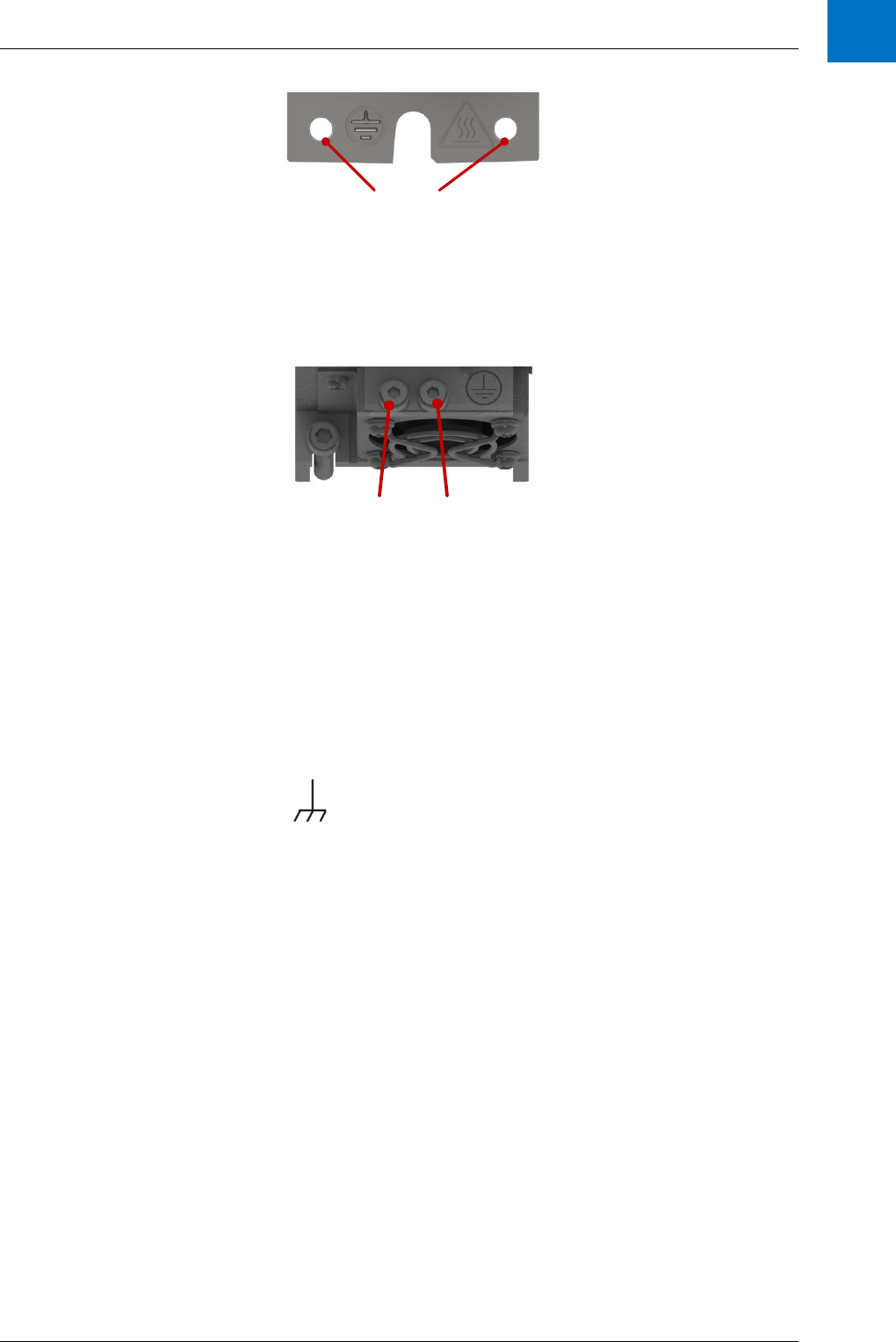
Power Wiring
ANCA Motion D-000088 Rev 06 29
6
Heatsink
PE connections
for 2 x M4 screws
Figure 6-4 D2103 PE Terminals
On the D2109, the mains PE is connected to 2 x M4 screw terminal at this bottom end of the drive heat sink area
via the supplied M4 screws.
Heatsink
PE connections
for 2 x M4 screws
Figure 6-5 D2109 PE Terminals
In multiple drive installations, each drive must be individually wired to a common PE point. Do not daisy chain PE
connections from one drive to the next.
The AMD2000 drive is designed to be installed on an unpainted metal gear tray e.g. galvanized surface which
forms an equipotential bond to all equipment mounted on the same gear tray. This minimizes voltage differences
to all grounded connections and enhances the immunity of equipment against conducted and radiated RF
disturbance. The gear tray must be connected to the supply PE, and is designated the Chassis Earth.
Symbol for Chassis Earth
PE connections using the optional armature bracket are described and illustrated in 6.7.2.1 Cable Shielding.
6.5 Installations conforming to the EMC Directive
EMC stands for Electromagnetic compatibility. It is the ability of electrical/electronic equipment to operate without
problems within an electromagnetic environment. The equipment must not disturb or interfere with any other
product or system within its locality. Variable speed drives are a source of interference, and all parts which are in
electrical or airborne connection within the power drive system (PDS) are part of the EMC compliance.
The drive interference is generated from the output voltage waveform which is a rapidly changing voltage
waveform (Pulse Width Modulation). The voltage transitions present on all motor cables and motor windings
induce parasitic common mode currents (I
LEAK
) in the stray capacitance of the motor and cable system. See
Figure 6-6 Common Mode Noise Current Paths in a Drive System. The common mode currents return to the
drive inverter by the lowest available impedance paths which must be carefully managed to prevent interference
voltages being generated in other equipment connected to the same earth system. The internal common mode
capacitors of the drive provide one return path (I
DC
) to the drive, and the EMI filter provides another return path
via the drive mains input.
To ensure the installation conforms to the EMC Directives, both of the following actions must be completed by the
installer;
1. Select appropriate EMC components, and
2. Implement appropriate wiring setups to limit high-frequency harmonic effects.

AMD2000 Series D21xx Servo Drive - User Guide
30 D-000088 Rev 06 ANCA Motion
Warning: EMC related performance, however, can still be influenced by factors not covered by the
configuration details supplied in this section of the user guide. It is difficult to consider all necessary wiring
and conditions of the equipment particular to all possible customer needs. For this reason, the EMC
conformance of the system as a whole must be confirmed by customer in accordance to the appropriate
standards for their application and market.
IGBT Inverter
Line Filter AMD2000
Motor Cable
I
leak
PE terminal and metal gear tray ground
PE
I
PCC
Converter Cabin et
LF
I
DC
I
Heatsink
Line Reactor
Figure 6-6 Common Mode Noise Current Paths in a Drive System
6.5.1 For 3 phase supply system wiring
Figure 6-7 shows the recommended EMC components for wiring of a 3 phase supply system. An EMI filter and a
3 phase line reactor are installed on the input power side. P1 and P2 should be linked using a smallest feasible
length wire at full drive current rating.
D2103 or D2109
LC1
LC2
L1
L2
L3
P1
P2
Line Reactor
PE
3 Phase
Supply
PE
EMI Filter
Circuit
Breaker
Figure 6-7 EMC components installation for a 3 phase supply

Power Wiring
ANCA Motion D-000088 Rev 06 31
6
Recommended EMC components for a 3 phase supply
EMI Filters
D2103 3 phase supply
Schaffner 3 phase 10A EMI Filter
FN3270H-10-44
D2109 3 phase supply
Schaffner 3 phase 20A EMI Filter
FN3270H-20-44
Line Reactors
D2103 3 phase supply
3.06mH, 7.6A
Hammond Power Solutions
CRX07D6AC
Or equivalent
D2109 3 phase supply
1.64mH, 14A
Hammond Power Solutions
CRX0014AC
Or equivalent
6.5.2 For 1 phase supply system wiring
Figure 6-8 shows the recommended EMC components for wiring of a 1 phase supply system. An EMI filter is
installed on input power side and a DC choke is installed on the DC BUS side between P1 and P2.
D2103 or D2109
LC1
LC2
L1
L2
L3
P1
P2
PE
1 Phase
Supply
PE
DC Choke
EMI Filter
Circuit
Breaker
Figure 6-8 EMC Components Installation for a 1 Phase Supply
Recommended EMC Components for a 1 Phase Supply
EMI Filters
D2103 1 phase supply
Schaffner Single-phase 8A EMI Filter
FN 350-8-29
D2109 1 phase supply
Schaffner Single-phase 20A EMI
Filter FN 350-20-29
DC Chokes
D2103 1 phase supply
10mH, 5A
Hammond Power Solutions
159ZJ
Or equivalent
D2109 1 phase supply
5.46mH(*), 14A
Hammond Power Solutions
CRX0014BC
Or equivalent
(*) – The 5.46mH 14A DC choke for the D2109 is a 3 phase line reactor (2.73mH, 14A); Figure 6-9 illustrates the
wiring.

AMD2000 Series D21xx Servo Drive - User Guide
32 D-000088 Rev 06 ANCA Motion
A1 A2 B1 B2 C1 C2
IN
OUT
Figure 6-9 Wiring needed to make a DC Choke from a 3 Phase Line Reactor
6.5.3 Installation guidelines of EMC components
Install the EMC components as close as possible to the drive.
A shielded cable is recommended if the distance between the EMI filter and the drive exceeds
30cm.
Minimize cross talk of “clean” lines (mains supply to filter input) due to “noisy” power cables by
careful routing and cable segregation.
Ensure EMC components mounted on a galvanised steel or bare aluminium panel with a
minimum thickness of 3mm to provide a low impedance return path. Otherwise, connect the
EMC components to a gear tray with minimal length flat copper braid strap.
Connect EMC components to PE for safety requirements, but note that the PE cable does not
provide a low impedance return path for common mode currents due to its cable length and the
skin effect of conductors. Best EMC equipotential bonding is achieved using careful mounting
or use of braided earth straps (refer to 6.4 Grounding).
Minimize motor cable length, and use correctly shielded motor cables (refer to 6.7.2 Motor
Power Cable Installation). For longer cable lengths a ferrite ring on the drive output will reduce
EMC noise.
Ensure that the EMI filter is always used with a line inductor or DC choke that reduces rms
currents, otherwise these may lead to currents exceeding the filter’s rating.

Power Wiring
ANCA Motion D-000088 Rev 06 33
6
6.6 Power Disconnect and Protection Devices
Install a manually-operated mains supply disconnecting device between the AC power source and the drive. The
disconnecting device must be of a type that can be locked to the open position for installation and maintenance
work and must comply to Safety of Machinery standard EN 60204-1 and local regulations.
The AMD2000 must have suitable input power protection on each phase input. This must conform to the
requirements and applicable safety regulations of the region of operation. An appropriate approval for switches is
IEC 60947-2 and for circuit breakers IEC 60947-3.
When using 2 phases of a 3-phase supply, each phase must have suitable protection and the voltage must not
exceed the rated input voltage.
When using a single phase supply with a Neutral conductor, protection is only required on the supply phase.
Recommended AC circuit breakers and supply wire sizes
Drive Type and
current output
rating (A rms)
AC
supply
Max.
Input
Current
(rms)
Circuit
breaker
(C-type)
Minimum Ø
wire gauge
AWG
mm
2
AMD2103, 3A
1Φ power
5A
6A
16
1.5
3Φ power
5A
6A
16
1.5
1Φ
control
0.5A
2A
20
0.5
AMD2109, 9A
1Φ power
13A
16A
14
2.5
3Φ power
13A
16A
14
2.5
1Φ
control
0.5A
2A
20
0.5

AMD2000 Series D21xx Servo Drive - User Guide
34 D-000088 Rev 06 ANCA Motion
Recommended DC circuit breakers and supply wire sizes
Drive Type and
current output
rating (A rms)
DC supply
Max.
Input
Current
DC
Circuit
breaker
DC rating
(C-type)
Minimum Ø
wire gauge
AWG
mm
2
AMD2103, 3A
Power
3A
4A
16
1.5
Control
0.5A
1A
20
0.5
AMD2109, 9A
Power
9A
10A
14
2.5
Control
0.5A
1A
20
0.5
Note: All wire sizes are based on 75 °C (167 °F) copper wire. Use of higher temperature cable may
allow smaller gauge wires. Size cables to conform to the local electrical installation regulations.
The mains supply wire should be used for the following power connections:
AC supply to external EMC filter
AC supply (or external EMC filter) to drive
Cable sizes are a guidance only as installation methods such as grouping, length, use of
conduits and ambient temperature may affect current capacity
Where more than one cable per terminal is used the combined diameters should not exceed
the maximum.
The terminals are suitable for both solid and stranded wires.
Circuit Breakers must be thermal magnetic type.
Motor cables should have the same wire gauge as 3 phase mains supply.
6.7 Motor Connections
AMD2000Motor
P.E.
U
V
W
(Optional) Motor
circuit Contactors
Minimise
unshielded
lengths
Connect PE
to drive
heatsink
Earth shield connected
360° to gear tray or
armature bracket
Figure 6-10 Motor connections and shielding
Connect correct phase wires (U, V, W) to the servo motor to ensure the servo motor operates correctly.
Do not connect AC mains power supply directly to the drive U, V, W terminals, otherwise damage may occur to
the drive.

Power Wiring
ANCA Motion D-000088 Rev 06 35
6
The PE for the motor must be connected to the M4 screw terminal at one end of the drive heat-sink,
preferably at the end closest to the armature motor connector. Do not connect directly to the mains supply
protective earth as this will increase EMC noise.
6.7.1 Motor Circuit Contactors
A motor circuit contactor may be installed if required by local codes or for safety reasons. The motor circuit
contactor isolates the motor fully from the drive to allow maintenance and form part of a safety system.
Ensure that shielding of the motor cable is continued on both sides of the motor circuit contactor as shown in
Figure 6-10 Motor connections and shielding.
6.7.2 Motor Power Cable Installation
6.7.2.1 Cable Shielding
In order to comply with the EMC requirements and minimize effects to other equipment, motor cables and power
supply cables from line filter AMD2000 drive must be used with shields. The cable shield minimizes
electromagnetic noise which may be coupled into nearby conductors, and the shield provides a low impedance
path for common mode noise currents back to the drive via EMC filter or drive common mode capacitors. Figure
6-10 Motor connections and shielding which illustrates the path of common currents. The gear tray layout and
correct bonding of the shield in the cabinet is a critical component in managing EMC problems. The following
guidelines must be followed.
Cables between the inverter and motor must be shielded, and the shield grounded at both
ends.
Use motor cables with dedicated PE conductor(s). Do not use the shield as a PE.
The shield clamping surface must be free of paint.
Use specifically designed shield clamps. Do not use plastic ties.
Select shield connections with low impedance in the MHz range.
Shield clamps can be with or without mechanical strain relief
Metallic components in the gear tray and cabinet must have a large surface area and should be
connected to one another with a high level of RF conductivity.
6.7.2.1.1 D2103 Cable Shielding
Use an Armature Bracket in order to terminate the shielded cable assembly.
The Armature Termination Bracket assembly consists of the following parts:
Armature Termination Bracket
EMC Saddle Clamp
3 x M4 screws
1 x M6 screw
Please see 11.4.7 Armature Cable Shield for bracket ordering details.
Clamp the Armature Termination Bracket down as shown below using the 2 x M4 existing
screws that came with the drive. Maximum tightening torque is 2.5Nm.
Carefully remove the Armature cable sheath to expose the metal braid. Expose approximately
25mm of braid length.
The position of the exposed braid is to coincide with the EMC Saddle Clamp and the metal
bracket as shown below in order to provide sufficient contact for termination.
Tighten the Saddle Clamp screw to 0.5Nm.
Fit the armature plug into the armature connector on the drive.

AMD2000 Series D21xx Servo Drive - User Guide
36 D-000088 Rev 06 ANCA Motion
Ensure that the Armature Cable Earth wire is connected to an M4 ring lug using one M4 screw
from the Armature Termination Bracket assembly kit, and connect to the bracket as shown
below. Maximum tightening torque is 1.5Nm.
The Armature Termination Bracket has been designed to allow the Protective Earth (PE) wires
to be connected in two ways.
a) Connection for two PE wires less than 10mm² Cu by using two M4 screws. Maximum
tightening torque is 1.5Nm.
b) A single PE wire if the conductor size is greater than 10mm² Cu by using a single M6
screw. Maximum tightening torque is 3Nm.
Armature Cable
Assembly
Exposed Braid
Armature Cable
Earth Wire
Two Protective
Earth Wires to
the Cabinet Earth
Bar
Termination
Bracket
EMC Saddle
Clamp
Figure 6-11 Armature Cable Shield Connection with 2 x PE wires

Power Wiring
ANCA Motion D-000088 Rev 06 37
6
Armature Cable
Assembly
Exposed Braid
Armature Cable
Earth Wire
A single
Protective Earth
Wire to the
Cabinet Earth Bar
Termination
Bracket
EMC Saddle
Clamp
Figure 6-12 Armature Cable Shield Connection with 1 x PE wire

AMD2000 Series D21xx Servo Drive - User Guide
38 D-000088 Rev 06 ANCA Motion
6.7.2.1.2 D2109 Cable Shielding
Use an Armature Bracket in order to terminate the shielded cable assembly.
The Armature Termination Bracket assembly consists of the following parts:
Armature Termination Bracket
EMC Saddle Clamp
3 x M4 screws
1 x M6 screw
Please see 11.4.7 Armature Cable Shield for bracket ordering details.
Clamp the Armature Termination Bracket down as shown below using the 2 x M4 existing
screws that came with the drive. Tightening Torque 2.5Nm max.
Carefully remove the Armature cable sheath to expose the metal braid. Expose approximately
25mm of braid length.
The position of the exposed braid is to coincide with the EMC Saddle Clamp and the metal
bracket as shown below in order to provide sufficient contact for termination.
Tighten the Saddle Clamp screw to 0.5Nm as recommended by the manufacturer.
Fit the armature plug into the armature connector on the drive.
Ensure that the Armature Cable Earth wire is connected to an M4 ring lug using one M4 screw
from the Armature Termination Bracket assembly kit, and connect to the bracket as shown
below. Maximum tightening torque is 1.5Nm.
The Armature Termination Bracket has been designed to allow the Protective Earth (PE) wires
to be connected in two ways.
a) Connection for two PE wires less than 10mm² Cu by using two M4 screws. Maximum
tightening torque is 1.5Nm
c) A single PE wire if the conductor size is greater than 10mm² Cu by using a single M6
screw. Maximum tightening torque is 3Nm.
See below for the interactions for the shielded armature termination.
Armature Cable
Assembly
Exposed Braid
Armature Cable
Earth Wire
Two Protective
Earth Wires to
the Cabinet Earth
Bar
Termination
Bracket
EMC Saddle
Clamp
Figure 6-13 Armature Cable Shield Connection with 2 x PE wires

Power Wiring
ANCA Motion D-000088 Rev 06 39
6
Armature Cable
Assembly
Exposed Braid
Armature Cable
Earth Wire
Single Protective
Earth Wire to the
Cabinet Earth Bar
Termination
Bracket
EMC Saddle
Clamp
Figure 6-14 Armature Cable Shield Connection with 1 x PE wire
6.7.2.1.3 Continuation of Motor Power Cable Shielding
Depending on the motor connector type, the armature cable shielding at the motor end should be terminated in
one of the following ways:
1. If the motor has a metal connector on the motor housing and the armature cable shield is
terminated at this motor connector
o Armature shielding will inherently be connected to the motor casing and no further
work is required at the motor end of the armature cable.
2. If the motor connector housing is not metal or the armature cable shield is not terminated at the
motor connector
o Add a metal P-Clip or equivalent to the armature cable at a location that is close to the
motor for earthing the shield.
o In order to add this part to the Armature Cable, remove a sufficient amount of outer
sheath in order to make direct contact with the exposed metal braid.
o Ensure that the metal braid is not damaged in this process.
o Affix the metal P-Clip to bare metal as close to the motor as possible, on the motor
housing itself if possible. The shield is required to have a good electrical connection to
the machine earth.

AMD2000 Series D21xx Servo Drive - User Guide
40 D-000088 Rev 06 ANCA Motion
Motor
Metal P-Clip
Exposed Metal Braid
Armature Cable from 3A
or 9A Drive
Figure 6-15 Armature Cable Shield Termination with metal P-Clip at Motor End
The below graphic shows a typical Earth Bar installation that may exist on the cabinet. Connect the Protective
Earth wires to the Earth bar as shown. Each protective earth Wire will be from a drive in the cabinet.
Protective Earth Wires to
the Drive Earthing points
(see above pictures for
locations)
Factory Earth Wire
Figure 6-16 Use Star Topology to Connect Drive Protective Earth to Earth Bar

Power Wiring
ANCA Motion D-000088 Rev 06 41
6
6.7.2.2 Cable Routing
In a drive system the return common mode currents flow through shields, cabinets, gear tray and earth wiring to
create localized parasitic ground potentials, which may affect control signals using the ground as a common
voltage reference. Careful planning of cable routing and location of shield grounds must be done to minimise
influence of parasitic ground potentials, and ensure compliance with EMC requirements. The following guidelines
must be followed.
Physically separate “noisy” and “clean” cables at the planning stage. Pay special attention to
the motor cable. The area around the shared terminal strip for the mains input and motor output
is particularly at risk.
All cable routing in an enclosure should be mounted as close as possible to gear tray or
grounded cabinet walls; “free-floating cables” act as both active and passive antennae.
Use twisted pair wires wherever possible to prevent interference from radiated common mode
noise sources. Continue the twist as close as possible to terminals.
Use shielded twisted pairs for analogue and control level wires exiting from the overall
enclosure.
Keep power and control wiring separate. Crossing at right angles is permitted, but no significant
parallel runs should be allowed, and cables should not share cable trays, trunking or conduits
unless they are separately shielded and the shields correctly terminated
Avoid mixing pairs with different signal types e.g., 110 V AC, 230 V AC, 24 V DC, analogue,
digital.
If plastic trunking/ducting is used, secure it directly to installation plates or the framework. Do
not allow spans over free air which could form an antenna.
Keep shield pigtails as short as possible and note they are less effective than full clamping
Allow no breaks in the cable shields.
Earthing connections should be as short as possible in flat strip, multi-stranded or braided
flexible conductors for low RFI impedance.
6.8 Drive Output Filters
6.8.1 Sinusoidal Filter
Sine-wave filters are designed to let only low frequencies pass. High frequencies are consequently shunted away
which results in a sinusoidal phase to phase voltage waveform and sinusoidal current waveforms. Sine wave
filters are recommended for the following applications:
Reduction of motor acoustic switching noise
Motors that are not “inverter rated” which have reduced insulation levels and can only accept
sinusoidal inputs supplies
Retrofit installations with old motors that are not “inverter rated”
Motors that require reduced bearing currents to prolong motor life and reduce service intervals
Step up applications or other applications where the frequency converter feeds a transformer
Note: Sine-wave filters must be selected for the drive switching frequency of 8kHz. Sinusoidal filters with
nominal frequency higher than 8kHz cannot be used.
Standard sine wave filters are connected to the drive output as shown in Figure 6-17 Motor Connections and
Shielding with Standard Sinusoidal Filter. For more demanding applications, sine wave filters with DC bus
connections can also be used as shown in Figure 6-18 Motor Connections and Shielding and DC Link Sinusoidal
Filter. There is an output voltage drop of approximately 5-10% across the sinusoid filter.

AMD2000 Series D21xx Servo Drive - User Guide
42 D-000088 Rev 06 ANCA Motion
Configuration
Recommended Sinusoidal
Filters*
Recommended EMC Filter Specs*
Rated
Current
Typical motor
Power Rating
DC Link
Voltage
(Max)
D2103 with no DC bus connection
3-phase 4A sine wave
4A
1.5kW
-
D2103 with DC bus connection
3-phase 4A sine wave
4A
1.5kW
850V
D2109 with no DC bus connection
3-phase 12A sine wave
12A
5.5kW
-
D2109 with DC bus connection
3-phase 12A sine wave
12A
5.5kW
850V
*Motor frequency range is from 0-200Hz for these filters
AMD2000Motor
P.E.
U
V
W
Minimise
unshielded
lengths
Connect PE
to drive
heatsink
Earth shield
connected
360° to gear
tray
Sinusoidal
Filter
Figure 6-17 Motor Connections and Shielding with Standard Sinusoidal Filter
AMD2000Motor
P.E.
U
V
W
Minimise
unshielded
lengths
Sinusoidal
Filter
+-
DC bus
terminals
Figure 6-18 Motor Connections and Shielding and DC Link Sinusoidal Filter

Power Wiring
ANCA Motion D-000088 Rev 06 43
6
6.8.2 du/dt Filter
The du/dt filters consist of inductors and capacitors in a low pass filter arrangement and their cut off frequency is
above the nominal switching frequency of the drive. Compared to Sine-wave filters they have lower L and C
values, thus they are cheaper and smaller, and have less voltage drop (approximately 0.5%). With a du/dt filter
the voltage wave form is still PWM shaped but the current is sinusoidal. The reduced performance of the du/dt
filter compared to the sinusoid filter makes it unsuitable for motor bearing current reduction and acoustic noise
reduction.
6.9 Motor Brake Connection
Some motors require the use of a brake to prevent motor movement when power is removed. The motor’s brake
must be wired up to a relay which is controlled by the 24V digital output 1 (DO1), on connector X4. The relay
must be wired with a protective fly-back diode as shown to prevent damage to the output circuit.
Relay:
Normally
Open
Motor
AMD2000
CN4/X4
DO-01
24V
19
20 or 21
Separate Customer
24V DC supply
24V 0V
Figure 6-19 Motor Brake Interface Circuit
To engage the brake:
The motor is brought to rest under normal control;
The relay is deactivated, causing the brake to engage;
The drive is disabled, removing power from the motor.
To disengage the brake:
The drive is enabled;
The drive applies power to the motor to hold position under normal control;
The relay is activated, causing the brake to be disengaged.
The D21xx contains a configurable brake release delay after the motor is enabled to prevent undesired
movement, refer to the AMD2000 Series Servo Drive – CoE Configuration Guide or AMD2000 Series Servo Drive
– SoE Configuration Guide for more information. It is also sometimes necessary to include a small delay after the
relay has been activated, before starting motion. This delay allows time for the relay contacts to engage and the
brake to release.
The 24V DC power supply for the brake must be a separate supply as brake wires often carry noise, and
generate a large voltage spike which may affect other devices connected to the brake supply. Do not use the
D21xx 24V supply from X4 to power the brake. The separate 24 V DC supply used for the motor brake can also
be used to power the relay in the thermal switch circuit.

AMD2000 Series D21xx Servo Drive - User Guide
44 D-000088 Rev 06 ANCA Motion
6.10 Motor Thermal Switch
Some motors provide thermal switch to prevent the motor overheating. The motor’s thermal switch must be wired
up to a relay which generates a 24V digital input on connector X4. Any of digital inputs DI-01 to DI-08 may be
used and DI-01 is shown in Figure 6-20 Motor Thermal Switch Interface Circuit.
Relay:
Normally
Open
Motor
AMD2000
CN4/X4
24V
DI-01
20 or 21
7
Separate Customer
24V DC supply
24V 0V
Figure 6-20 Motor Thermal Switch Interface Circuit
The 24V DC power supply for the thermal switch must be a separate supply as it can often carry noise that could
cause erratic drive operation, and may not provide sufficient isolation. Do not use the D21xx 24V supply from X4
to power the thermal switch. The separate 24 V DC supply used for the thermal switch can also be used to
power the relay in the brake circuit.
Note: There must be reinforced isolation between voltage windings and the temperature sensor as
required by IEC 60204-1 and referenced standards.
6.11 Motor Thermal Sensor
Some motors provide a thermal sensor to give feedback of motor temperature. This model of drive does not
feature a dedicated analogue input for this function. If using an external CNC, the motor thermal sensors can be
connected to one of the drive analogue inputs by means of a voltage divider or two voltage dividers as indicated
in the diagrams and have the monitoring implemented in the CNC. The user is then responsible for converting the
non-linear voltage output from the circuit into an equivalent temperature for the temperature sensor
selected. Two temperature sensors are recommended as in Figure 6-22 Example Connection of Two Thermal
Sensors in a bridge configuration instead of one sensor. The reasons for this is increased noise immunity
because there is twice as much voltage per degree of temperature change, and also because the voltage feeding
the divider does not affect the measurement. If this configuration is used the temperature sensors must be co-
located; that is they must be in approximately the same physical location.

Power Wiring
ANCA Motion D-000088 Rev 06 45
6
24V
(e.g. Pin 20, X4)
KTY84
3.9k
Ain+ Ain-
AGND
(e.g. Pin 3, X4)
0V
(e.g. Pin 46, X4)
Figure 6-21 Example Connection of Single Motor Thermal Sensor
24V
(e.g. Pin 20, X4)
KTY84
3.9k
Ain+
Ain-
3.9k
KTY84
AGND
(e.g. Pin 3, X4)
0V
(e.g. Pin 46, X4)
Figure 6-22 Example Connection of Two Thermal Sensors
Note: that there must be reinforced isolation between voltage windings and the temperature sensor as
required by IEC 60204-1 and referenced standards.
6.12 Motor Thermal Estimation
An alternative to a Motor Thermal Switch or Motor Thermal Sensor is Motor Thermal Estimation. This is a
software feature within the drive which measures the motor current draw and estimates the build-up of residual
heat in the motor. Based on this estimate of the motor heat errors can be triggered if the estimate passes a
defined threshold. Please see the applicable AMD2000 Series Servo Drive – CoE Configuration Guide or
AMD2000 Series Servo Drive – SoE Configuration Guide for details regarding the configuration of Motor Thermal
Estimation.
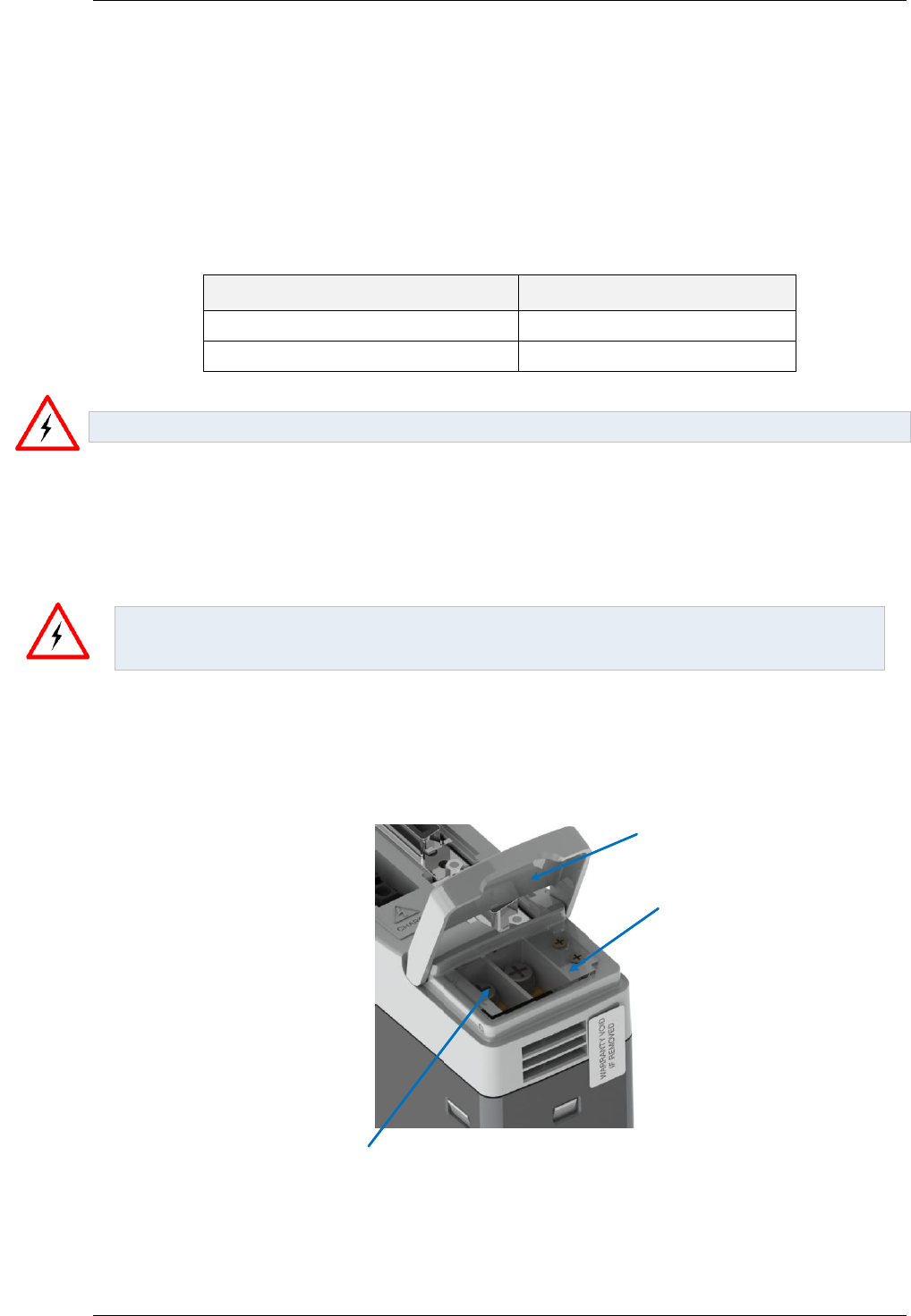
AMD2000 Series D21xx Servo Drive - User Guide
46 D-000088 Rev 06 ANCA Motion
6.13 Brake/Regeneration Resistor
The D21xx drives feature an inbuilt regeneration resistor. Regeneration refers to the process whereby when the
motor is actively providing energy to the drive and then stops, the kinetic energy in the entire mechanical system
connected to the shaft of the motor gets transferred to the bus capacitance in the drive, which increases the
voltage. This happens because of the motor inductance. When the voltage on the bus capacitance exceeds
385V the drive will connect the internal regeneration resistor in addition to any external regeneration resistor that
is provided by the user.
Mode
Connection
Internal Regeneration Resistor
Link pins P & D
External Regeneration Resistor
Connect resistor to P & C
Danger: Do not short circuit connector P to C. Connector P is live with active high voltage.
Please refer to sections 10.4.5 Regenerative Braking and 10.9 Regeneration Resistor for additional information.
6.14 DC Busbar Terminals
Danger – High Voltage Area: If you require to access the busbar screw terminals ensure that the drive
has been fully discharged. Refer to the Product Rating Sticker on the side of the drive for further
information.
The 3A and 9A drives contain 4 x DC busbar screw terminals. These are located under the flip lid as shown. A
clear plastic cover is fitted in order to restrict access to these screw terminals. These busbar screw terminals
must only be uncovered and accessed when the drive is completely discharged. The clear plastic cover is
required to be fitted as shown unless otherwise stated.
Busbar Flip lid
Busbar Screw
Terminals
Clear plastic
cover
Figure 6-23 D2103 DC busbar screw terminal arrangement

Power Wiring
ANCA Motion D-000088 Rev 06 47
6
Busbar Flip lid
Busbar Screw
Terminals
Clear plastic
cover
Figure 6-24 D2109 DC busbar screw terminal arrangement
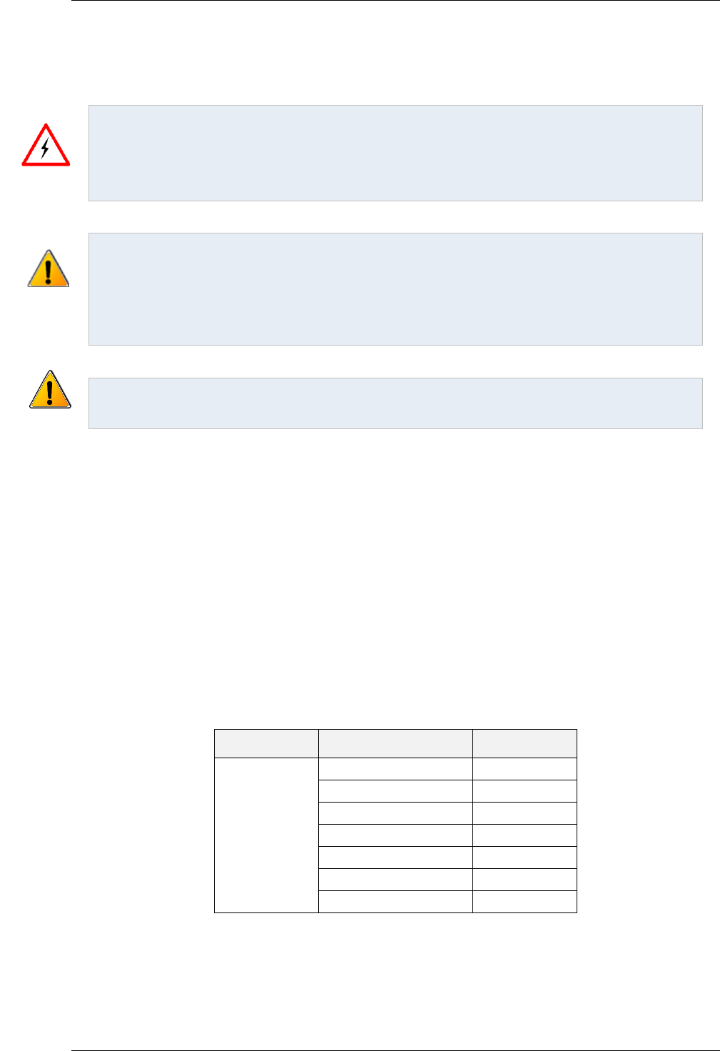
AMD2000 Series D21xx Servo Drive - User Guide
48 D-000088 Rev 06 ANCA Motion
7 Control Wiring
DANGER: The working DC bus is live at all times when power is on. The Main Isolator feeding the drive
must be switched to the off position at least 15 minutes before any work is commenced on the unit. The
operator must check the bus voltage with a tested working voltage measuring instrument prior to
disconnecting any connectors or opening the DC Bus terminal cover. The red LED indicator on the front of
the drive which indicates that there is charge remaining in the drive is only to be used as an aid to visual
troubleshooting. It shall not be relied on as a means of safety.
Warning: Do not plug or unplug connectors while power is applied. It is recommended that the drive is
installed with an upstream circuit breaker that is rated appropriately depending on the model of AMD2000
drive being installed.
Turn the Main Disconnect mains isolator switch to the Off position.
Following the appropriate lockout procedure, place a sign over the isolation switch clearly indicating to
other personnel that this isolator is not to be touched.
All secondary side control wiring (connectors X1, X2, X3, X4 and X5) and control devices must maintain
reinforced isolation to harmful primary side voltages in order that the reinforced isolation characteristics of
the drive are not compromised.
7.1 What this Chapter Contains
This chapter contains information related to interfacing of the drives to the following connections:
- Analogue and Digital I/O
- STO
- EtherCAT
- Motor Feedback
7.2 Analogue I/O
All analogue Input and Output signals are connected to the drive via X4 with the following pins,
Connector
Pin Number
Label
X4
or
I/O Module
1
AI-01+
26
AI-01-
2
AI-02+
27
AI-02-
28
AO-01
29
AO-02
3, 4, 30, 31
AGND
Please refer to section 10.3 Interface Specifications for detailed specifications
7.2.1 Analogue Inputs
The analogue inputs pass through a differential buffer and second order low-pass filter with a cut-off frequency of
approximately 700 Hz.

Control Wiring
ANCA Motion D-000088 Rev 06 49
7
7.2.1.1 Idealised drawing of Analogue Input Circuit
+
AMD2000
AI+
AI-
AGND
7.2.1.2 Typical Connection Examples of Analogue Input
Vs
+
Signal source AMD2000
AI-XX+
AI-XX-
Figure 7-1 Typical Example of Ground Referenced Differential Input Connection
Vs
+
Signal source AMD2000
R1 R2
AI-XX+
AI-XX-
AGND
Figure 7-2 Typical Example of Floating Differential Input Connection
Note: R1 and R2 (10KΩ<R1=R2<100KΩ) are bias resistors to keep input common-mode voltage level
within the common-mode voltage range of AMD2000 analogue input circuit.
Vs
+
Signal source AMD2000
AI-XX+
AI-XX-
AGND
Figure 7-3 Typical Example of Ground Referenced Single-Ended Connection
Note: In the scenario presented in Figure 7-3, any potential difference (in many cases this is 50/60Hz
powerline noise) between signal source ground and measurement system ground will be picked up into
the measurement result.

AMD2000 Series D21xx Servo Drive - User Guide
50 D-000088 Rev 06 ANCA Motion
Vs
+
Signal source AMD2000
AI-XX+
AI-XX-
AGND
Figure 7-4 Typical Example of Floating Single-Ended Connection
+
AMD2000
AI-XX+
AI-XX-
AGND
24V DC
0V
1kΩ, 0.25W
Potentiometer
1.5kΩ, 0.25W
Figure 7-5 Typical Input Circuit to Provide 0-10V Input from a 24V Source
Refer to the applicable AMD2000 Series Servo Drive - Configuration Guide for detailed information on how to use
ANCA MotionBench to read analogue input values.
7.2.2 Analogue Outputs
The analogue outputs can be used to output configurable analogue values from the drive.
It is recommended that shielded twisted pair cable is used for interfacing. The shield connection should be made
at one end only.
Refer to the applicable AMD2000 Series Servo Drive - Configuration Guide for detailed information on how to use
ANCA MotionBench to read analogue output values.
7.2.2.1 Idealized Drawing of Output Circuit
AMD2000
DSP
AO
DAC

Control Wiring
ANCA Motion D-000088 Rev 06 51
7
7.3 Digital I/O
All digital Input and Output signals are available via connector X4. The AMD2000 provides:
8 x General Purpose Inputs
2 x additional General Purpose Inputs can be configured if required
6 x General Purpose Outputs
Please find details specifications in section 10.3 Interface Specifications
Connector
Pin Number
Label
X4
or
I/O Module
(ICN-3077-1150)
7
DI-01
8
DI-02
9
DI-03
10
DI-04
11
DI-05
12
DI-06
13
DI-07
14
DI-08
15
DI-09+
16
DI-09-
17
DI-10+
18
DI-10-
19
DO-01
22
DO-02
23
DO-03
24
DO-04
25
DO-05
34
DO-06
20, 21
+24V-Fused
1
46, 47
+24V-GND
1
Refer to the AMD2000 Technical Data for maximum current rating.

AMD2000 Series D21xx Servo Drive - User Guide
52 D-000088 Rev 06 ANCA Motion
7.3.1 24V Control Circuit Supply
The maximum current that can be drawn from this supply is 500 mA total. Note that if a motor with a brake is
required this may be insufficient current to release the brake, so an external power supply will be required. Any
external power supply must be of the Separated Extra Low Voltage (SELV) type, and approved to IEC 60950.
This 24V control supply is primarily electronically protected with the addition of a self-resetting semi-conductor
fuse. The effects of exceeding the 500 mA limit depend on the magnitude of the overload.
The reference ground for this 24V control supply is +24V-GND (X4 pins 46 & 47). This reference ground must be
connected to the chassis ground (gear tray), in order to establish a “control ground” for the installation.
7.3.2 Digital Inputs
Digital Input Overview
DI-01 – DI08 are electrically isolated through opto-couplers.
DI-09 – DI10 are not isolated.
Reference ground is +24V-GND (X4 pins 46 & 47)
Refer to the applicable AMD2000 Series Servo Drive - Configuration Guide for detailed information on how to use
ANCA MotionBench to read digital input values.
Application examples for the digital inputs include:
Positive Limit switch
Motor over-temperature
Negative Limit switch
Home switch
7.3.2.1 General Purpose Digital Inputs DI-01 to DI-08
Warning: Please refer to section 10.3 Interface Specifications for detailed current ratings of the 24V
supply if used to switch I/O devices
7.3.2.1.1 Idealised Drawing of Input Circuit
DI
AMD2000
DSP
0V

Control Wiring
ANCA Motion D-000088 Rev 06 53
7
7.3.2.1.2 Typical Connection Example
AMD2000
DI-XX
DSP
0V
Control
Control GND
+24 V
7.3.2.1.3 Typical Connection Example NPN
Pull-Up
Resistor
NPN Device
AMD2000
DI-XX
DSP
Control GND
0V
+24 V
1K 1W

AMD2000 Series D21xx Servo Drive - User Guide
54 D-000088 Rev 06 ANCA Motion
7.3.2.2 Differential Inputs DI-09 & DI-10
Section 10.3 Interface Specifications provides detailed information on these two differential inputs. If 2 additional
digital inputs are required this may be done safely via optional I/O interface Module accessory listed in 11.4.2 I/O
Interface.
7.3.2.2.1 Idealized Drawing of Differential Input Circuit
AMD2000
DSP
DI+
DI-
7.3.2.2.2 Typical Connection Examples of interfacing with PNP/NPN based sensors.
24 V
4k 4k
4k
DI+
DI-
Signal Sensor
AMD2000
Figure 7-6 - Example PNP Based Sensor

Control Wiring
ANCA Motion D-000088 Rev 06 55
7
24V
4k
4k
4k
DI+
DI-
Signal
Sensor
AMD2000
Figure 7-7 – Example NPN Based Sensor
7.3.2.2.3 Connecting 24V single-ended signals using optional I/O module (646-0-05-0723).
See table below for operations of the single-ended inputs when using the 646-0-05-0723 module.
Attribute
Qualification
Nominal Operating Voltage
24 V
Maximum Voltage
30 V
Maximum Input Low Threshold Voltage
5 V
Minimum Input High Threshold Voltage
11 V
Nominal Input Current at 24V Input
15 mA
Control
Control GND
+24 V
GND(24V)
I/O Interface module
(646-0-05-0723)
DI-09-/DI-10-
GND (DI-09+/DI-10+)
Figure 7-8 – Interface with 24V single-ended signals

AMD2000 Series D21xx Servo Drive - User Guide
56 D-000088 Rev 06 ANCA Motion
The digital Input and Output signals available via I/O Module (646-0-05-0723) connected to X4 are as follows:
Connector
Pin Number
Label
Function
I/O Module
(646-0-05-0723)
7
DI-01
Digital Input
8
DI-02
Digital Input
9
DI-03
Digital Input
10
DI-04
Digital Input
11
DI-05
Digital Input
12
DI-06
Digital Input
13
DI-07
Digital Input
14
DI-08
Digital Input
15
DI-09+
Internal Ground
(not requiring a GND connection)
16
DI-09-
single-ended Input
17
DI-010+
Internal Ground
(not requiring a GND connection)
18
DI-10-
single-ended Input
19
DO-01
Digital Output
22
DO-02
Digital Output
23
DO-03
Digital Output
24
DO-04
Digital Output
25
DO-05
Digital Output
34
DO-06
Digital Output
20, 21
+24V-Fused
2
+24V
(requiring a GND connection)
46, 47
+24V-GND
GND
(requiring a GND connection)
48-50
Not Connected
51
GND
Internal Ground
(not requiring a GND connection)
52
GND
Internal Ground
(not requiring a GND connection)
Please find details specifications in section 10.3 Interface Specifications
2
Refer to the AMD2000 Technical Data for maximum current rating.
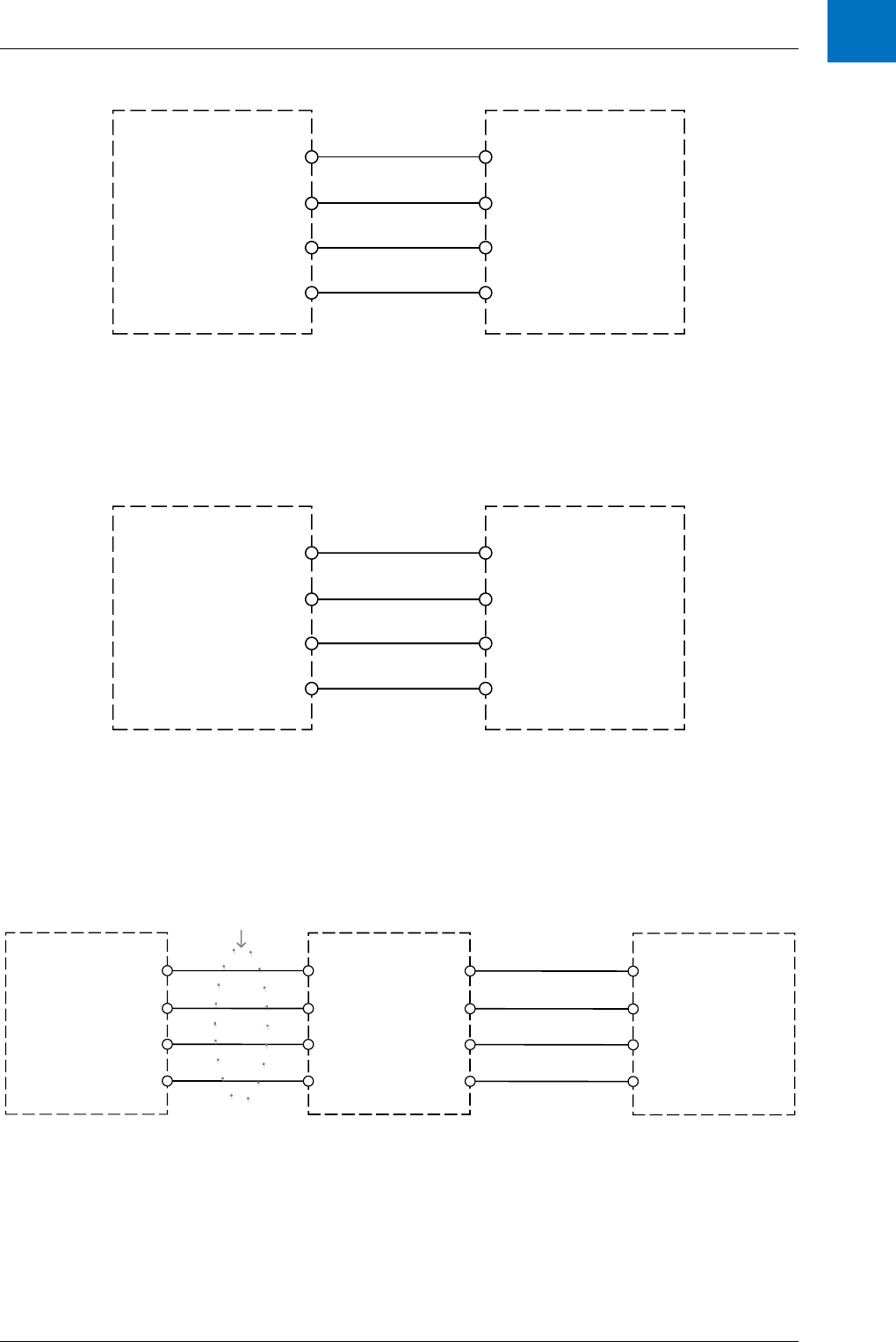
Control Wiring
ANCA Motion D-000088 Rev 06 57
7
7.3.2.2.4 Connecting a Differential Quadrature Pulse Position Input Device
B+
B-
A+
A-
AMD2000 DRIVE (X4)
MODE: Quadrature
Quadrature Device
(Customer Specific)
The drive does not provide power to the quadrature device so the power supply
must be provided by the user.
Ensure the ground is common to the ground of the drive so the power supply
and signals have a common ground.
DI-09+
DI-09-
DI-10+
DI-10-
Figure 7-9 - Differential Quadrature Mode Wiring Diagram
7.3.2.2.5 Connecting a Differential Pulse and Direction Position Input device
DI-09+
DI-09-
DI-10+
DI-10-
DIR+
A+
A-
AMD2000 DRIVE (X4)
MODE: Pulse & Direction
Pulse & Direction Device
(Customer Specific)
DIR-
The drive does not provide power to the quadrature device so the power supply
must be provided by the user.
Ensure the ground is common to the ground of the drive so the power supply
and signals have a common ground.
Figure 7-10 - Differential Pulse and Direction Mode Wiring Diagram
7.3.2.2.6 Connecting a Single Ended Quadrature Pulse Position Input device
B
Digital GND
AMD2000 DRIVE (X4)
MODE: Quadrature
Quadrature Device
(Customer Specific)
The drive does not provide power to the quadrature device so the power supply must be provided by the user.
Ensure the ground is common to the ground of the drive so the power supply and signals have a common ground.
DI-09+
DI-09-
DI-10+
DI-10-
15
16
17
18
I/O Module
(646-0-05-0723)
15
16
17
18
A
Digital GND
50 Way
SCSI Cable
Figure 7-11 - Single Ended Quadrature Mode Wiring Diagram

AMD2000 Series D21xx Servo Drive - User Guide
58 D-000088 Rev 06 ANCA Motion
7.3.2.2.7 Connecting a Single Ended Pulse and Direction Position Input device.
DI-09+
DI-09-
DI-10+
DI-10-
AMD2000 DRIVE (X4)
MODE: Pulse & Direction
Pulse & Direction Device
(Customer Specific)
The drive does not provide power to the quadrature device so the power supply must be provided by the user.
Ensure the ground is common to the ground of the drive so the power supply and signals have a common ground.
15
16
17
18
I/O Module
(646-0-05-0723)
15
16
17
18
50 Way
SCSI Cable
DIR
Digital GND
A
Digital GND
Figure 7-12 - Single Ended Pulse and Direction Mode Wiring Diagram
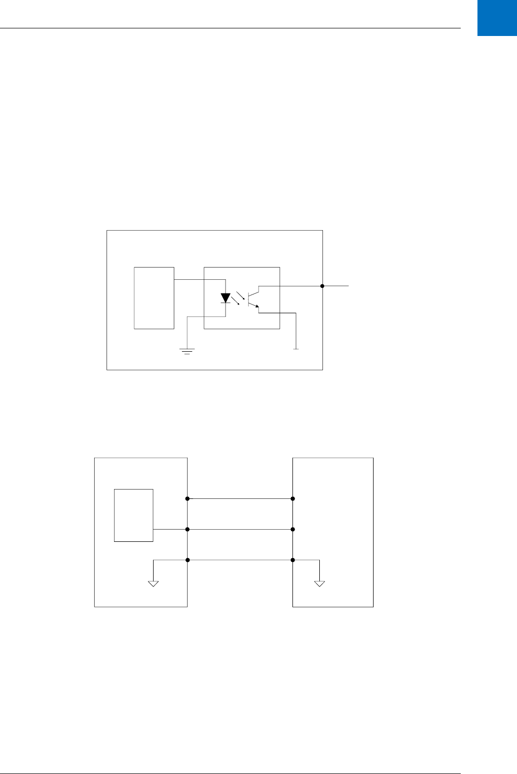
Control Wiring
ANCA Motion D-000088 Rev 06 59
7
7.3.3 Digital Outputs
The digital outputs can be used to output pre-programmed functions stored in the drive e.g. relay control.
Digital Output Overview
Outputs are current sinking
Refer to Section 10.3 Interface Specifications for maximum current ratings
All Digital outputs are pulled to ground
7.3.3.1 Idealized Drawing of Digital Output Circuit
AMD2000
DSP
0 V
DO-XX
Refer to the applicable AMD2000 Series Servo Drive - Configuration Guide for detailed information on how to use
ANCA MotionBench to read digital output values.
7.3.3.2 Typical Connection Examples
24V (X4 Pin 20)
AMD2000 Example - PLC
DSP
DO-XX
DI-XX

AMD2000 Series D21xx Servo Drive - User Guide
60 D-000088 Rev 06 ANCA Motion
AMD2000
Relay
DO-XX
24V
(e.g. X4 Pin 20)
24 V
(External)
Load
AMD2000
Contactor
DO-XX
0V
24 V Power
Supply
Load
(X4 Pin 46 or 47)
3 Φ Supply
7.4 Safe Torque Off (STO) Operation
7.4.1 Definitions
STO
The Safe Torque Off function.
Safe State
The drive can no longer supply power/torque to its motor.
Active or Activated
The STO has been triggered and the drive will either be attempting to
reach its Safe State, or has reached its Safe State, where it is unable
to deliver power or torque to its associated motor. The STO function
may be triggered via an external demand (see Demand below), or as
an internal consequence of its own fault detection mechanisms.
Demanded, Requested or Asserted
STO has been requested to Activate as a result of detecting a de-
powering of the STO inputs.
Standby
STO has not been activated.
SFR-A/SFR-B
STO Fault Relay output A/STO Fault Relay output B.

Control Wiring
ANCA Motion D-000088 Rev 06 61
7
7.4.2 STO Overview
7.4.2.1 Introduction
The AMD2000 servo drive (model D21xx) has a Safe Torque Off function that interrupts torque producing power
being provided to a motor. STO provides a SIL Claim Level 3 safety function according to IEC 61800-5-2:2007, or
an equivalent performance level of PL=e, Category 4, according to ISO 13849-1:2006.
Warning: In order to claim these levels of safety performance in an installation, it is the machine
builder’s, or integrator’s, responsibility to use suitably qualified and experienced personnel to design,
commission and operate safety systems for the application of interest. STO in the drive itself is not the
sole basis for claiming SIL or PL when installed on a machine.
3
STO can be used to prevent unexpected start-up of the motor without having to shut the drive down or remove
input power. STO works by disabling the internal PWM signals so that the power module connected to the motor
cannot be turned on.
Warning: STO will not brake the motor (STO performs a function similar to Stop category 0, IEC 60204-
1) so, if moving, the motor will only coast to a stop when STO is activated.
STO is implemented with two separate inputs that must be powered for the drive to be able to operate. In this
condition STO is considered to be operating in standby. STO has detected no faults (internal or external), and
has received no demand to activate. An AMD2000 I/O interface module is required to setup STO and power must
be applied to the STO connections of this I/O module. This power can be provided by either the internal 24V
power supply of the AMD2000 drive or from an external power supply (See notes on the bottom of section 7.4.5.1
about requirements and approvals on an external power supply).
AMD2103 or AMD2109
Controller
3-Phase
V
W
U
Fault Relay
NC during use
Motor
STO Input 1
STO Input 2
Figure 7-13 STO Implementation
Warning: STO does not remove AC power from the drive itself. If maintenance or repair work is to be
carried out on the machine, the drive should be isolated from all power supplies first. Please read the User
Guide for isolation requirements and techniques. You must also wait for 15 minutes after power removal
for internally stored energy to discharge.
Warning: It is not recommended to stop the drive using the STO function as this is an uncontrolled stop.
The motor will only coast to a stop and depending on the application this may result in unacceptable
behaviour.
3
Guidance regarding staff levels of training and competence are given in IEC 61508.

AMD2000 Series D21xx Servo Drive - User Guide
62 D-000088 Rev 06 ANCA Motion
Warning: When using a three phase permanent magnet synchronous motor and in the case of multiple
gate failure, the motor may unexpectedly rotate up to 180 electrical degrees (180/p mechanical degrees
where p is the number of poles).
7.4.3 STO Considerations
Suitably qualified, trained and authorised personnel must configure and commission STO for
use on a machine.
A hazard analysis must be carried out to evaluate safety risks and to design a suitable safety
system in which STO may be integrated.
This drive must be installed in a suitable location under suitable ambient conditions (see
section 10.5 Environmental Specifications).
Acceptance tests must be performed to verify the correct operation of the safety system and
STO function of this drive. The acceptance test procedure (see section 7.4.8 STO Function
Commissioning Test Procedure) should be carried out after any of the following occur:
o On initial installation and commissioning of the safety function.
o After making any changes to the system including wiring, components or settings.
o Any time a STO Override Plug (11.4.5 STO Override Plug) is removed from the X4
interface for the purpose of returning STO to operation.
o After any maintenance of the machine or machine safety system.
The STO feature contains no user maintainable components, and will therefore not require any
user maintenance. No opening of the drive for maintenance should be attempted, and any
such attempt will result in the STO feature no longer being considered as providing a safe
function. Anti-tamper stickers are clearly shown on the drive to discourage such maintenance.
Replacement of the fan assembly on the D2109 is specifically exempt and is the only
maintenance allowed on the Drive.
This STO feature is designed for uncontrolled stops (similar to Stop category 0, IEC 60204-1);
only removing torque from the motor. The speed at which the motor and load moves after
activation may depend on many factors.
7.4.4 STO Operation
The drive contains two separate STO inputs that must both be used. When both inputs are powered and no fault
has been detected, STO is in a standby state and the drive will operate normally. Table 7.4.2.1-1 - STO Input
Ratings describes the STO input requirements.
STO input
Nominal
Maximum
Units
Input Voltage
24 (+/-20%)
30
VDC
Input current
10
mA
Table 7.4.2.1-1 - STO Input Ratings
Warning: If either STO input is energised above approximately 30 V damage may occur to the drive.
STO is activated (i.e. asserted) when power is removed from either STO input for a duration longer than 1ms.
Correct operation requires both inputs to be asserted simultaneously for a similar duration. The AMD2000 allows
for both inputs to assert or de-assert within 120 ms of each other for this purpose. A duration separating a
change in demand to each input of longer than 120 ms may result in a fault condition. In either situation, the
drive will achieve its Safe State and no energy will be supplied to the motor.
Whenever the STO inputs are asserted, the blocking of energy supply to the motor is a SILCL 3 certified
safety function and will occur within 50 ms of the assertion.
Whenever the STO function indicates a fault through either of its fault relays, the blocking of energy
supply to the motor is a SILCL 3 certified safety function and will occur within 50 ms of detecting a fault
(faults are described in detail in 7.4.6 Fault detection).

Control Wiring
ANCA Motion D-000088 Rev 06 63
7
Depending on the operating mode of the drive, STO assertion (without faults) can result in two different
outcomes;
1. If the drive was in an ‘enabled’ state when STO was asserted, an error will be registered by the drive
along with STO blocking power delivery to the motor. There are two different sequences that may be
employed to reset from STO in this situation;
4
a. The recommended sequence is to first disable the drive, then clear the drive error, and
subsequently de-assert (24V) the STO inputs, but
b. It is also possible to reset to normal operation by de-asserting (24V) the STO inputs, and then
clearing the drive error while the drive remains enabled.
In either approach it is the responsibility of the machine integrator or installer to appropriately
assess the hazards, given the understanding that de-asserting STO removes the drive’s safety
system block on power being delivered to the motor.
2. If the drive was NOT ‘enabled’ when STO was asserted, then the safety function will simply remove
power from the motor. The drive may be reset to normal operation by simultaneously de-asserting
(24V) both STO inputs. De-asserting STO inputs while not enabled, results in immediately allowing
power to be delivered to the motor and the drive will not display any errors in normal operation (ie. no
faults).
Warning: STO performs a reliable removal of energy supply to the motor ONLY when both STO inputs
are asserted. It is the responsibility of the machine builder or integrator to determine whether additional
safety systems are required to maintain power removal from the motor if STO is de-asserted while the
drive is ‘enabled.’ Care should be exercised, as the drive does not reliably and safely block power
delivery to the motor when STO inputs are de-asserted, unless a fault has occurred in the STO system.
Warning: It is the responsibility of the machine builder or integrator to determine whether additional
safety systems are required to maintain power removal from the motor if STO is to be de-asserted while
the drive is NOT ‘enabled.’
If a fault in STO does result, from either too long a duration between STO input assertions matching, or some
other fault detection reaction internal to the drive, then the drive must be restarted (turn off for more than 2
seconds, then turn on
5
) in order to recover to under normal operating conditions (ie. no faults
6
). If the motor and
load associated with the drive was moving at the time when STO was demanded, it may only coast to a stop. In
this state the motor will not be able to be driven, nor resist external forces/torques, regardless of what the drive
commands.
Application of motor torque becomes possible when both STO inputs are re-powered, and all fault/error
conditions are cleared. This will allow the drive to operate normally and any commanded drive activity will have to
be set running again.
Warning: Applying a sequence of shorter than 1ms assertions can still result in STO if the durations of
de-assertion (24V) between each assertion are shorter than 10 ms.
Note: Both STO inputs must change within the 120ms timing window, whether asserting or de-asserting
STO or the drive may trigger a fault reaction as described in 7.4.6 Fault detection.
Note: Some safety programmable logic controllers (PLCs) have test pulse features. The AMD2000
(D2103 or D2109) is designed so that it will not respond to STO assertions (0V) on the inputs of 1ms or
less in duration, as long as the intervening periods of de-assertion at least 10ms or longer.
4
Refer to the AMD2000 Series Servo Drive - Configuration Guide for instructions on how to clear drive errors, or disable and
re-enable the drive.
5
If the drive is not turned off for a long enough duration, it is possible the fault will not be cleared, and the drive will remain in
the safe state.
6
If an internal fault is re-detected on start-up, or if the inputs asserting STO continue to not match, then STO will re-enter a fault
state upon start-up and will continue to be unable to deliver power to a motor.

AMD2000 Series D21xx Servo Drive - User Guide
64 D-000088 Rev 06 ANCA Motion
7.4.5 STO Wiring
Warning: Wiring of the AMD2000 for STO must be designed and commissioned by suitably qualified
personnel.
STO uses an isolated dual channel implementation so that the function is fault tolerant, however both channels
need to be asserted or de-asserted within 120ms for the drive to not detect a fault. IO pins and nominal voltages
for each are given in the following table. It is not necessary to use the drive’s internal power supply to power the
STO inputs, but any external power supply must be suitably PELV and must be appreciated for its impact on the
safety function by qualified personnel, such as by approval to IEC 60950.
Name
AMD2000 I/O interface module
Nominal voltage
+STO 1
45
+24VDC
-STO 1
43
0VDC
+STO 2
49
+24VDC
-STO 2
50
0VDC
SFR-A
5
+24VDC
SFR-B
6
+24VDC
+24V
20 & 21
+24VDC (output)
0V
46 & 47
0VDC(output)
Table 7.4.2.1-1 - STO connections
Warning: The STO inputs are electrically isolated from each other, and isolated from the internal +24V
power supply. Cable inputs should be suitably wound, suitably separated, shielded and grounded, and
may not exceed 15 m in length. Avoid tight bending and installations leading to abrasion in the cable.
If STO is not required for machine safety, then both STO channels can be connected directly to the drive’s own
24V power supply as described in section 7.4.5.5 When STO is not required, or some other suitable 24V power
supply. Example wiring diagrams are given elsewhere in this document (see 7.4.5.1 Example Wiring Installation
for a Single AMD2000 using STO and 7.4.5.2 Example Wiring Installation for Multiple AMD2000 using STO).
Any switching contacts on the STO inputs must operate within 120ms of each other; otherwise a fault will be
detected as described in section 7.4.6 Fault detection.
A number of common external failure modes result in safe state via the action of the STO function.
In the event that a STO input (IO 45,43 and/or IO 49,50) is wired with reverse polarity, the STO circuit
will detect a STO assertion on that channel, and the drive will enter the safe state.
STO input wires that fail to transmit the required threshold voltage (eg. due to corrosion) will be detected
as STO assertion on that channel, and the drive will enter the safe state.
Similarly, cable disconnections or failures to connect will also result in STO assertion.
If either of the above failure modes occurs on just one channel, then this fault will be registered by the
drive by opening its fault relay.
Some external failure modes are difficult to detect via the actions of the STO function alone (for example, crossed
wiring of inputs), so information regarding the sensed levels of STO inputs, STO reactions and faults can be
examined via ANCA MotionBench software or the drive’s EtherCAT fieldbus. MotionBench and EtherCAT STO
related signals are described in the AMD2000 Series Servo Drive – CoE Configuration Guide or AMD2000 Series
Servo Drive – SoE Configuration Guide.
7.4.5.1 Example Wiring Installation for a Single AMD2000 using STO
When using single drive in a machine, the STO wiring may be wired as shown in Figure 7-14 – Single drive STO
wiring example below.

Control Wiring
ANCA Motion D-000088 Rev 06 65
7
5
6
45
+24VDC
STO FAULT
RELAY
STO-01+
STO-01-
SFR-A
SFR-B
STO FAULT
RELAY OUTPUT
STO-02+
STO-02-
D2103 or D2109
I/O interface module
0V
Safety circuit
43
49
50
PE
Figure 7-14 – Single drive STO wiring example
Note: The internal +24V power supply has a limited output capability (refer to the AMD2000 User Guide
for details). Over current protection inside the drive will cause the +24V output to cease if too much load is
connected. If this supply is shared between STO and the six digital outputs, then you must ensure that
you stay under the current limit threshold. If the limit is exceeded, it will cause the STO function to activate
and therefore, stop the motor. If you are concerned about power supply loading causing false STO trips,
then it is recommended that a reliable external power supply is used. Note that any external power supply
must be of the Protected Extra Low Voltage (PELV) type and approved to IEC 60950.
7.4.5.2 Example Wiring Installation for Multiple AMD2000 using STO
When using multiple drives in a machine, the STO wiring may allow daisy chaining to each of the drives as
shown in Figure 7-15 - Multiple drives STO wiring example.
Warning: It is the machine builder’s responsibility to ensure the correct design and installation of the
safety systems on a machine for hazard reduction. Such ‘daisy chains’ are not always suitable.
In this example the STO channels are powered from an external +24V DC power supply (see notes in Table
7.4.2.1-1 - STO Input Ratings about external power supply requirements and approvals). The voltage rating of
the external power supply should be compatible with the conditions listed in Table 7.4.2.1-1 - STO Input Ratings.
Each channel will draw the current listed in Table 7.4.2.1-1- STO Input Ratings, so the power supply should be
sized accordingly taking into account the number of drives in parallel.

AMD2000 Series D21xx Servo Drive - User Guide
66 D-000088 Rev 06 ANCA Motion
5
6
45
+24VDC
STO FAULT
RELAY
STO-01+
STO-01-
SFR-A
SFR-B
STO FAULT
RELAY OUTPUT
STO-02+
STO-02-
D2103 or D2109
I/O interface module
0V
Safety circuit
43
49
50
5
6
45
STO FAULT
RELAY
STO-01+
STO-01-
SFR-A
SFR-B
STO FAULT
RELAY OUTPUT
STO-02+
STO-02-
D2103 or D2109
I/O interface module
43
49
50
PE
Figure 7-15 - Multiple drives STO wiring example
Note: If you are wiring multiple drives together, 24V power requirements must be carefully considered. If
using the AMD2000 internal power supply, be careful not to exceed power supply current limits (refer to
the note at the bottom of section Table 7.4.2.1-1 - STO Input Ratings). Failure to do so may result in
activation of over current protection and may therefore cause unexpected STO activation.

Control Wiring
ANCA Motion D-000088 Rev 06 67
7
7.4.5.3 Example of Integrating a Single STO drive with a Safety Circuit
The following example uses a Safety Relay Module as an example of a safety circuit to demonstrate integration
to a single STO drive
5
6
45
STO FAULT
RELAY
STO-01+
STO-01-
SFR-A
SFR-B
STO-02+
STO-02-
D2103 or D2109
I/O interface module
43
49
50
+24VDC
0V
Control
Contactor Mirror
Contacts (If applicable)
RESET (As per 60204-1)
(Restart Loop)
Emergency
Stop Button
Safety Relay
Module
PE
Figure 7-16 Example of Integrating Single STO Drive to Safety Circuit
Note: Requirement for IEC60204-1 regarding earth fault detection must be followed.
Note: Installation of the safety circuit will need to follow particular installation instructions for chosen unit
and requirements of IEC 60204-1.
7.4.5.4 Example of Integrating a Two STO drives with a Safety Circuit
The following example uses a Safety Relay Module as an example of a safety circuit to demonstrate integration
to two STO drives
5
6
45
STO FAULT
RELAY
STO-01+
STO-01-
SFR-A
SFR-B
STO-02+
STO-02-
D2103 or D2109
I/O interface module
43
49
50
+24VDC
0V
Control
Contactor Mirror
Contacts (If applicable)
RESET (As per 60204-1)
(Restart Loop)
Emergency
Stop Button
Safety Relay
Module
5
6
45
STO FAULT
RELAY
STO-01+
STO-01-
SFR-A
SFR-B
STO-02+
STO-02-
D2103 or D2109
I/O interface module
43
49
50
PE
Figure 7-17 Example of Integrating 2 STO drives to Safety Circuit
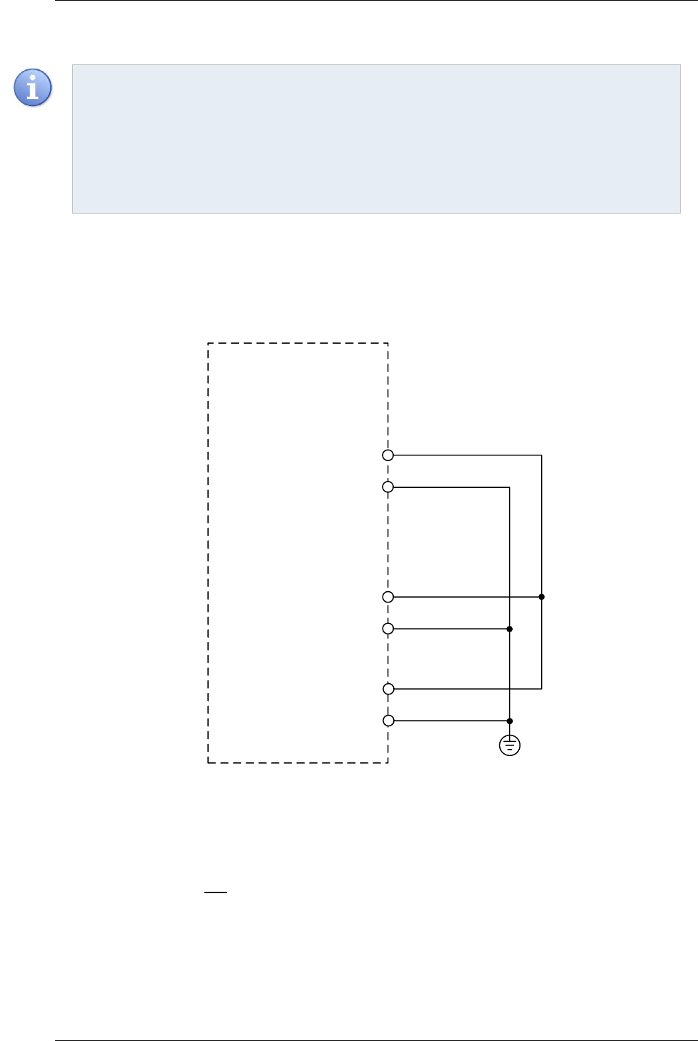
AMD2000 Series D21xx Servo Drive - User Guide
68 D-000088 Rev 06 ANCA Motion
Note:
1. Requirement for IEC60204-1 regarding earth fault detection must be followed.
2. Installation of the safety circuit will need to follow particular installation instructions for chosen unit
and requirements of IEC 60204-1.
If you are wiring multiple drives together, 24V power requirements must be carefully considered. If using
the AMD2000 internal power supply, be careful not to exceed power supply current limits (refer to the note
at the bottom of section Table 7.4.2.1-1 - STO Input Ratings). Failure to do so may result in activation of
over current protection and may therefore cause unexpected STO activation.
7.4.5.5 When STO is not required
If STO is not required, loopback wires may need to be installed onto the AMD2000 I/O interface module as
shown in Figure 7-18 - STO feature not used. Without this wiring the drive cannot operate. Also, refer to the note
in section Table 7.4.2.1-1 - STO Input Ratings about power supply loading. There is no requirement to use the
AMD2000 internal power supply in this instance, but this is displayed here for convenience.
45
STO-01+
STO-01-
STO-02+
STO-02-
D2103 or D2109
I/O interface module
43
49
50
+24V
GND(24V)
20/21
46/47
PE
Figure 7-18 - STO feature not used
7.4.6 Fault detection
Any detected fault in STO results in both STO activation, and the opening of the fault relay. The drive must be
power cycled (turned off, wait 10 seconds and turn on) before it will be able to recover from a fault. STO
incorporates both internal and external fault detection.

Control Wiring
ANCA Motion D-000088 Rev 06 69
7
External detection is provided by examination of the STO inputs. For correct operation of STO, both of the STO
inputs must always have the same logic level. If a difference is detected for a long enough duration, then STO is
activated and the fault relay is opened. This is intended to prevent bouncing contacts or mechanical differences
between the STO activation circuits from tripping false errors. Differences shorter than 120ms will not be detected
as a fault. Differences longer than 240ms will be detected as a fault and the fault relay will be opened. Any
duration of difference between 120ms and 240ms will result in an uncertain consequence, which may or may not
be detected as a fault. Refer to Figure 7-19 - STO Timing Diagrams and Table 7.4.5.5-2 - STO Timing
Specifications for more details.
Internal detection is provided by examination of the power delivered to both high and low side opto-couplers to
the gates. Monitoring detects agreement in power supply levels between these two sets of opto-couplers, as well
as their independent power levels.
The fault relay is a voltage free relay output accessed via the AMD2000 I/O interface module. Do not exceed
100mA on its contacts. This output is always in the ‘closed’ position when no fault has been detected. If a fault is
tripped, the output switches to the ‘open’ position. This output is intended only for connection to an external
machine safety system or fault indicator. When a fault is indicated, the ‘open’ condition will remain and the drive
will remain in the Safe State no matter what signal is applied to the STO inputs. The only way to reset from a fault
and restore drive operation is to power cycle the drive. This is a deliberate mode of operation to ensure that the
operator is aware of any faults and cannot un-expectedly restart operation from such a fault condition. Table
7.4.5.5-1 - STO Fault Relay output ratings describes the STO Fault Relay output requirements.
STO Fault Relay output (SFR-A/SFR-B)
Nominal
Maximum
Units
Voltage
24 (+/-20%)
30
VDC
Sink/source current
100
mA
Table 7.4.5.5-1 - STO Fault Relay output ratings
Warning: If any input is energised above approximately 30 V damage may occur to the drive.
This fault detection circuitry does not ensure that STO is fault free and it is up to the machine builder and
operator to ultimately ensure machine safety. A fault might only be detected when the STO is activated, for
example. This might occur in the instance when a contact on one STO input is stuck on. One input will open in
response to a demand for STO, while the stuck input will not. This is only detectable upon demand. When STO is
not being demanded this fault is no longer detectable by the drive.
Warning: If a STO fault occurs, always test the STO feature before returning the drive back into service.
Faults in the operation of STO must be identified and logged immediately by the operator of the machine.
All faults MUST be reported to ANCA Motion, and no maintenance or repair of a drive is allowed. Faulty
drives should be returned to ANCA Motion for further evaluation.

AMD2000 Series D21xx Servo Drive - User Guide
70 D-000088 Rev 06 ANCA Motion
Assert Demand (0V)
No Demand (24V)
Torque/Power
STO Input 2
STO Fault
t
s
t
s
STO Input 1
STO NORMAL OPERATION
t
s
External STO FAULT DETECTED
t
d
t
g
t
d
t
m
t
m
t
m
t
m
No Fault (closed)
Fault (open)
No Demand (24V)
Torque Allowed
No Torque/Power Allowed
Assert Demand (0V)
Torque/Power
STO Input 2
STO Fault
STO Input 1
Figure 7-19 - STO Timing Diagrams
Parameters
Description
Values
Min (ms)
Max (ms)
t
s
Time between STO input demand asserted or de-asserted
N/A
N/A
t
d
Time between first STO input demand detected and Torque/Power shut down
N/A
50
t
g
Time below which STO demand changes are ignored (from safety PLC pulses, for
example)
N/A
1
7
t
m
Maximum time allowable between differing STO demands before external Fault
detected
120
240
Table 7.4.5.5-2 - STO Timing Specifications
7
t
g
assumes at least 10ms between low transitioning pulses

Control Wiring
ANCA Motion D-000088 Rev 06 71
7
7.4.7 STO Diagnostics
Warning: The STO function of the AMD2000 is entirely hardware based. No software, firmware or
diagnostics available through the drive firmware can or should be used in the formulation of safety
functions external to the drive. There is no claim made concerning the reliability of the STO diagnostic
software.
The drive controller does, however, see the status of the safety system and can display the appropriate error
code or status information under no fault conditions.
If STO is requested while moving a motor, or if the drive is commanded to move a motor while STO is
active, an error code will be reported and shown on the drive’s LED display. The error code for this
condition is E0070. This type of error can be cleared by de-asserting the STO inputs and sending a
reset error command to the drive via the EtherCAT interface. Refer to the AMD2000 Series Servo Drive
- Configuration Guide for details concerning resetting errors.
If the drive is not enabled (and therefore not able to move a motor) the drive may still be queried via
EtherCAT to determine if the STO is asserted, as this is considered a normal operating condition and
will not result in an error or fault. Refer to the AMD2000 Series Servo Drive - Configuration Guide for
details concerning how to access this information.
Alternatively, if STO has entered a fault condition, opening its fault relays (as described in 7.4.6 Fault detection)
then E0071, E0072 or E0073 will be reported on the drive’s LED. In this case, the error can only be reset by
power cycling the drive. If the cause of the fault persists after power cycling, then the error will not be able to be
cleared.
Note: The STO Diagnostics described in the section are NOT certified safety functions.
7.4.8 STO Function Commissioning Test Procedure
The purpose of this test is to ensure that STO is operating correctly.
Ensure there is no risk of injury to persons or property when testing the STO function of this drive, remember that
STO will not apply any braking to the motor connected to the drive; only remove torque. For this reason and for
general safety, low speeds and loads with as little inertia as possible are suggested to be used.
Disconnect the two STO inputs from the drive. Obtain two single pole double throw (DPST) switches. Wire as per
Figure 7-20 - STO Test Setup below.
Follow the flow charts described on the following pages in order to evaluate the STO function. There are three
sub-tests to be executed. Any single failure in any sub-tests leads to an overall failure.
Warning: Performance during this test should be logged by the operator of the machine, and assessed
by suitably qualified personnel for safety related functions. All faults or mis-performance/deviations from
this test procedure MUST be reported to ANCA Motion, and no maintenance or repair of a drive is
allowed. Please organise with ANCA Motion to return the drive for assessment.
Warning: The following tests use the motor becoming stationary as evidence of motor torque removal. Do
not use a part of the body to assess this.

AMD2000 Series D21xx Servo Drive - User Guide
72 D-000088 Rev 06 ANCA Motion
Figure 7-20 - STO Test Setup

Control Wiring
ANCA Motion D-000088 Rev 06 73
7
Start sub-test1
(Full STO Test)
Power up the drive with both STO inputs de-
asserted (Both S1 and S2 switch to POS1)
Enable the drive via software to turn the motor
at slow speed
Check STO
fault relay
Assert both STO channels simultaneously
(Switch S1 and S2 to POS2 simultaneously)
Check motor
stops running
Check STO
fault relay
De-assert both STO channels simultaneously
(Switch S1 and S2 to POS1 simultaneously)
Reset error and enable the drive via software to
turn the motor at slow speed
Check motor
starts running
Check STO
fault relay
End sub-test1 and
go to sub-test2
Test fails. Safely put machine into a safe
state, electrically isolate drive, remove
drive and contact ANCA Motion.
Open
Closed
No
Yes
Open
Closed
No
Yes
Open
Closed
Start STO Test
Check motor
starts running
No
Yes
Check for error
code: E0070
Yes
No
Figure 7-21 - STO Sub-Test 1

AMD2000 Series D21xx Servo Drive - User Guide
74 D-000088 Rev 06 ANCA Motion
Start sub-test2
(STO1 Test)
Power up the drive with both STO inputs de-
asserted (Both S1 and S2 switch to POS1)
Enable the drive via software to turn the motor
at slow speed
Check STO
fault relay
Assert STO1 only (Switch S1 to POS2 while keep
S2 in POS1)
Check motor
stops running
Check STO
fault relay
De-assert STO1 (Switch S1 to POS1 while keep
S2 in POS1)
Attempt to reset error and enable the drive via
software to turn the motor at slow speed
Check motor
starts running
Check STO
fault relay
Test fails. Safely put machine into a safe
state, electrically isolate drive, remove
drive and contact ANCA Motion.
Open
Closed
No
Yes
Closed
Open
Yes
No
Closed
Open
End sub-test2 and
go to sub-test3
Check motor
starts running
No
Yes
Check for error
code: E0071
Yes
No
Figure 7-22 - STO Sub-Test 2

Control Wiring
ANCA Motion D-000088 Rev 06 75
7
Start sub-test3
(STO2 Test)
Power cycle the drive with both STO inputs de-
asserted (Both S1 and S2 switch to POS1)
Enable the drive via software to turn the motor
at slow speed
Check STO
fault relay
Assert STO2 only (Switch S2 to POS2 while keep
S1 in POS1)
Check motor
stops running
Check STO
fault relay
De-assert STO2 (Switch S2 to POS1 while keep
S1 in POS1)
Attempt to reset error and enable the drive via
software to turn the motor at slow speed
Check motor
starts running
Check STO
fault relay
Test fails. Safely put machine into a safe
state, electrically isolate drive, remove
drive and contact ANCA Motion.
Open
Closed
No
Yes
Closed
Open
Yes
No
Closed
Open
End STO test
End sub-test3
Check motor
starts running
No
Yes
Check for error
code: E0071
Yes
No
Power cycle the drive with both STO inputs de-
asserted (Both S1 and S2 switch to POS1)
Check STO
fault relay
Open
Closed
Enable the drive via software to turn the motor
at slow speed
Check motor
starts running
No
Yes
Figure 7-23 - STO Sub-Test 3

AMD2000 Series D21xx Servo Drive - User Guide
76 D-000088 Rev 06 ANCA Motion
The test is now complete.
Warning: After the STO Commissioning Test is completed, it is imperative that extreme care is taken to
assemble the drive connections as per wiring recommendations in this user guide.
7.5 Motor Brake Control
A motor brake can be connected to any of the digital outputs as previously described. The maximum current
allowable is 500mA sink between all 6 digital outputs. Failure to observe this rating will result in damage to the
drive.
Refer to section 6.9 Motor Brake Connection.
7.6 Serial Communication Port
Use of the Serial Communication Port is not supported in the D21xx servo drive.
7.7 Ethernet Interface
7.7.1 EtherCAT®
8
AMD2000 supports the EtherCAT protocol with ‘Servo Profile over EtherCAT’ (SoE) and ‘CANopen over
EtherCAT’ (CoE) capability based on the IEC61800-7 standard. This protocol provides deterministic
communication over a standard 100Mbit/s (100Base-TX) Fast Ethernet (IEEE802.3) connection. This makes it
suitable for the transmission of control and feedback signals between the AMD2000 and other EtherCAT enabled
controllers.
AMD2000 functions as an EtherCAT slave controller, providing two ports (IN/OUT) for connection to other
EtherCAT compliant equipment. This allows nodes to be connected in many configurations such as a ring, star,
or tree, with EtherCAT’s self-terminating technology automatically detecting breaks or an intended end of line.
If only one port is used for EtherCAT operation, it must be the X1 (IN) port.
7.7.2 EtherCAT topology / Port assignment
8
EtherCAT® is a registered trademark and patented technology, licensed by Beckhoff Automation GmbH, Germany

Control Wiring
ANCA Motion D-000088 Rev 06 77
7
Loopback
Function
EtherCAT
Processing Unit
EtherCAT
Slave Controller
Port 0
Closed
Port 0 open
or all ports
closed
Auto-
forwarder
Loopback
Function
Loopback
Function
Port 1
Closed
Auto-
forwarder
Loopback
Function
In
Out
Port 3
Closed
Port 2
Closed
Port 1
Open
7.7.2.1 Possible EtherCAT Configurations are
IN OUT
IN
IN
IN
IN
IN
IN
IN
IN
OUT
OUT
OUT
OUT
OUT
OUT
OUT
OUT
EtherCAt Master
1 2 3
4 5 6 7 8 9
Straight Line Topology EtherCAT Network:
IN OUT
IN
IN
IN
IN
IN
IN
IN
IN
OUT
OUT
OUT
OUT
OUT
OUT
OUT
OUT
EtherCAt Master
1 2 3 4 5 6 7 8 9
Ring Topology EtherCAT network:
IN OUT
IN
IN
IN
IN
IN
IN
IN
IN
OUT
OUT
OUT
OUT
OUT
OUT
OUT
OUT
EtherCAt Master
IN OUT
IN
IN
IN
IN
IN
IN
IN
IN
OUT
OUT
OUT
OUT
OUT
OUT
OUT
OUT
IN
IN
OUT
OUT
External Switch
Multi-Branch EtherCAT network:
1 2 3
4 5 6 7 8 9
10 11 12 13 14 15 16 17 18 19 20
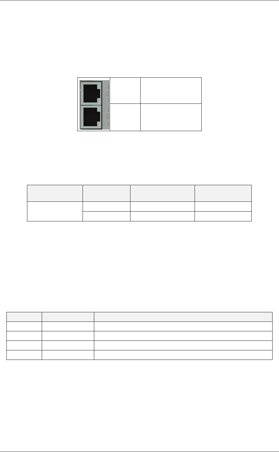
AMD2000 Series D21xx Servo Drive - User Guide
78 D-000088 Rev 06 ANCA Motion
7.7.2.2 EtherCAT Configuration
EtherCAT configuration is usually performed using EtherCAT manager software. To assist with configuration, an
EtherCAT Slave Information (ESI) file is provided in the firmware bundle. This .xml file describes the drive’s
capabilities to the EtherCAT manager.
7.7.2.3 EtherCAT Connectors
7.7.2.4 EtherCAT Cables
To connect the AMD2000 drive to other EtherCAT devices the following types of cables must be used with 8P8C
modular connectors. They are commonly referred to as “RJ45 shielded patch leads”.
Cable
Name
Cable Screening
Pair Shielding
Cat 5e or Above
F/UTP
Foil
None
SF/UTP
Screen and Foil
None
TP = twisted pair
U = unshielded
F = foil shielding
S = screened (braid type)
Either straight or crossover cables may be used. Recommended cables are listed in the accessories section. See
11.4.6 EtherCAT Cables for more information.
7.8 DIP Buttons
Button
Label
Function
SW4
MODE
Holding during power up will force the device into bootstrap mode
SW3
UP
Reserved
SW2
DOWN
Reserved
SW1
SET
Holding during power up will force the device into bootstrap mode
Additional functionality may also be available depending on variant, refer to the related AMD2000 Series Servo
Drive - Configuration Guide for more information.
X1
EtherCAT IN
X2
EtherCAT OUT

Control Wiring
ANCA Motion D-000088 Rev 06 79
7
7.9 Motor Encoder Feedback
In the case where encoders are integrated into motors only those with internal reinforced insulation
between hazardous voltage in the motor and encoder signal circuits can be used with the AMD2000 drive.
Connector
Pin Number
Label
Analogue
Encoder
9
Digital Incremental
Encoder
10
X5
1
Sin - / A-
Sin - / A-
-
2
Sin + / A+
Sin + / A+
-
3
Cos - / B-
Cos - / B-
-
4
Cos + / B+
Cos + / B+
-
5
Ref - / Z-
Ref - / Z-
-
6
Ref + / Z+
Ref + / Z+
-
7
A+
-
A+
8
A-
-
A-
9
B+
-
B+
10
B-
-
B-
11
Z+
-
Z+
12
Z-
-
Z-
13
9VDC
-
-
14
5VDC
5VDC
5VDC
15
GND
GND
GND
7.9.1 Analogue Encoder Interface
7.9.1.1 Idealized Drawing of the Analogue Encoder Circuit
DSP
A/B/Z +
A/B/Z -
AMD2000
X5
9
Encoder channel 1 is designed to support Sin/Cos encoders but can also be used for a secondary digital incremental encoder.
This channel does not support the UVW wire-saving FOI feature. Please refer to the accompanying configuration guide for
more information.
10
Encoder channel 2 is designed to support digital incremental encoders only.

AMD2000 Series D21xx Servo Drive - User Guide
80 D-000088 Rev 06 ANCA Motion
7.9.2 Analogue Encoder Cable
BACKSHELL BACKSHELL
TO SERVO DRIVE ENCODER
INNER SHIELD
OUTER SHIELD
SIN+
SIN-
COS+
COS-
REF+
REF-
5V
0V
SIN+
SIN-
COS+
COS-
REF+
REF-
5V
0V
NOTE:
(1) THE INNER AND OUTER SHIELD SHOULD NOT TOUCH AT ANY POINT
Figure 7-24 Typical Wiring Example of Analogue Incremental Encoder Wiring
7.9.3 Digital Encoder Interface
7.9.3.1 Idealized Drawing of the Digital Encoder Circuit
DSP
RS485
/RS422
Receiver
A/B/Z +
A/B/Z -
AMD2000
X5

Control Wiring
ANCA Motion D-000088 Rev 06 81
7
7.9.4 Digital Encoder Cable
BACKSHELL BACKSHELL
TO SERVO DRIVE
ENCODER
A+
A-
B+
B-
Z+
Z-
5V
0V
5V
0V
A+
A-
B+
B-
Z+
Z-
Figure 7-25 Typical Wiring Example of Digital Incremental Encoder Wiring
Recommended cables are listed in the accessories section 11.3.2 Encoder Cables
.

AMD2000 Series D21xx Servo Drive - User Guide
82 D-000088 Rev 06 ANCA Motion
7.9.5 Encoder Splitter Cable
Drive Connector (CN1)
Analogue Channel (CN2)
Digital Channel (CN3)
Pin Number
Signal
Pin Number
Signal
Pin Number
Signal
1
SIN-/A-
1
SIN-/A-
NC
2
SIN+/A+
2
SIN+/A+
NC
3
COS-/B-
3
COS-/B-
NC
4
COS+/B+
4
COS+/B+
NC
5
REF-/Z-
5
REF-/Z-
NC
6
REF+/Z+
6
REF+/Z+
NC
7
A+
NC
7
A+
8
A-
NC
8
A-
9
B+
NC
9
B+
10
B-
NC
10
B-
11
Z+
NC
11
Z+
12
Z-
NC
12
Z-
13
E+9V
NC
NC
N/A
14
E+5V
14
E+5V
14
E+5V
15
EGND
15
EGND
15
EGND
Backshell
Shield
Backshell
Shield
Backshell
Shield
CN1
CN2
CN3

Installation Checklist
ANCA Motion D-000088 Rev 06 83
8
8 Installation Checklist
8.1 What this Chapter Contains
This chapter contains a pre power up checklist aimed at ensuring safe and successful initial power up of the
drive.
8.2 Checklist
The installation location satisfies the requirements in 4.3.1 Installation Site and 10.5.3
Installation and Operation
An adequately sized protective earth connector is installed between the drive and the
installation Earth Bar
The required ventilation clearances around the drive have been observed per section 4
Mechanical Installation
An adequately sized protective earth connector is installed between the drive and the
motor.
Each protective earth conductor is connected to the appropriate terminal and is secured.
The supply voltage does not exceed 264V rms between L1, L2 and L3.
The input power cable is connected to the appropriate terminals and the conductors are
secured.
Appropriate supply circuit breakers and disconnect devices have been installed.
The motor cable is connected to the appropriate terminals, the phase order is correct and
the conductors are secured.
The brake resistor cable (if applicable) has been connected to the appropriate terminals
and the connections secure
The motor cable and brake resistor cable (if applicable) have been routed away from other
cables
No power factor compensation capacitors have been connected to the motor cable
A sinusoidal filter has been installed in between the motor armature output on the drive and
the motor if required by the application
All low voltage control cables have been correctly connected and are secure
There is no dust or other foreign object inside the drive after installation (E.g. Due to cutting
of cables etc.)
All wiring conforms to applicable regulations and standards
No physical damage is present to any component within the system

AMD2000 Series D21xx Servo Drive - User Guide
84 D-000088 Rev 06 ANCA Motion
The motor and all equipment connected to the drive is ready for start-up
A risk assessment has been completed on entire machine and is considered by the user to
be safe enough for operation
Regeneration energy and power has been assessed and external resistor has been
connected if required
There are no shorts between encoder power supplies and encoder GND
Possible load for all digital outputs does not exceed 500mA combined current sinking
The STO Commissioning Test has been completed and PASSED following the instructions
listed in Section 7.4.8, or if STO is not required, then the STO function has been disabled
appropriately in accordance with Section 7.4.5.5.

Start-up
ANCA Motion D-000088 Rev 06 85
9
9 Start-up
Please refer to the applicable configuration guides for this series of drive for parameter configuration, tuning and
diagnostics.
AMD2000 Series Servo Drive - SoE Configuration Guide
AMD2000 Series Servo Drive - CoE Configuration Guide

AMD2000 Series D21xx Servo Drive - User Guide
86 D-000088 Rev 06 ANCA Motion
10 Technical Data
10.1 What this Chapter Contains
This chapter contains information related to detailed specifications of the drive:
Control Functions
Interface Specifications
Electrical Specifications
Environmental Specifications
Mechanical Dimensions and details
De-Rating Curves
Standards Compliance
10.2 Control Functions
Attribute
Qualification
10.2.1 Control Modes
Linear control
Yes
Rotational control
Yes
Position control
Via EtherCAT (CoE/SoE) & Pulse Input
Velocity control
Via EtherCAT (CoE/SoE) & Analogue Voltage Input
Current/Torque control
Via EtherCAT (CoE/SoE)
Sinusoidal Permanent Magnet Servo Control
Yes
Sinusoidal Induction Motor Control
Yes
10.2.2 Thermal and over-current protection
Inverter heat-sink temperature limit
80° C
Adjustable dynamic current limiting
Yes
Adjustable continuous over-current monitoring
Yes
Adjustable instantaneous over-current monitoring
Yes
Surge protection
Yes (300 VAC)
10.2.3 Self-Protection features
Motor overload
Yes, see AMD2000 Series Servo Drive – CoE
Configuration or SoE Configuration Guides for
adjustment.
Over-travel limit exceeded
Yes
10.2.4 DC bus voltage control

Technical Data
ANCA Motion D-000088 Rev 06 87
10
Bus voltage monitor
Yes
Bus regeneration brake chopper
Yes
Bus over/under voltage adjustable limits
Yes
10.2.5 Advanced control functions
DC Bus compensation
Yes
Backlash compensation
Yes
Probing
Yes
Pre-defined Drive Controlled Moves (DCM)
Yes – up to 64 move segments
Drive Controlled Homing (DCH)
Yes
Field Orientation Modes
DQ Alignment
Preconfigured Offset
Acceleration Observer
Absolute
EtherCAT Slave Mode
Yes
Stand-alone Mode
Yes
Field Firmware Updates
Yes
Position Latch
Yes
Persistent Configuration Data
Yes ( via EEPROM)
Continuous ADC Calibration
Yes

AMD2000 Series D21xx Servo Drive - User Guide
88 D-000088 Rev 06 ANCA Motion
10.3 Interface Specifications
Attribute
Qualification
10.3.1 Digital I/O Supply
Nominal Operating Voltage
24 VDC -15%/+20%
Maximum Current
500 mA
Short Circuit Protected
Yes (resettable fuse)
10.3.2 24V Digital Inputs
Number of Inputs
8
Nominal Operating Voltage
24 V
Maximum Voltage
30 V
Minimum Input Must Detect Voltage
18 V
Maximum Must Not Detect Input Voltage
5 V
Input Current
20 mA
Input Impedance
1 kΩ
Maximum Propagation Delay
10 us
Isolated
Yes
10.3.3 24V Digital Outputs
Number of Outputs
6
Output Type
Low side MOSFET switch
Nominal Operating Voltage
24 V
Maximum Operating Voltage
30 V
Maximum Sink Current
500 mA total for all 6 outputs
while not exceeding 500 mA per output
Isolated
Yes
Short Circuit Protected
Yes
10.3.4 Differential Digital Inputs
Voltage rating
3V (RS-422 compliant)
Number of Inputs
2 (4 wires)
Input Common-Mode Voltage Range
+12/-7 V
Terminating Resistance
120 Ω
Turn On Differential Threshold
+200 mV
Turn Off Differential Threshold
-200 mV
Maximum Propagation Delay
130 ns
Isolated
No

Technical Data
ANCA Motion D-000088 Rev 06 89
10
10.3.5 Differential Digital Encoder Output
Voltage rating
5V
Number of Outputs
3 x line driver (6 wires)
Minimum Output High Voltage single ended W.R.T
GND
2.5 V @ 20 mA
Maximum Output Low Voltage single ended W.R.T
GND
0.5 V @ -20 mA
Maximum Current
±20 mA
Isolated
No
Short Circuit Protected
No
10.3.6 Analogue Inputs
Number of Inputs
2
Input impedance (DC)
20 kΩ
Input Voltage (Nominal Range)
±10 V
Input Voltage (Absolute Maximum Range)
±12.64 V
Bandwidth
700 Hz
Isolated
No
10.3.7 Analogue Outputs
Number of Outputs
2
Output Voltage (Nominal Range)
±10 V
Output Voltage (Absolute Maximum Range)
±12.25 V
Output Current (Nominal)
+/-10 mA
Short circuit protection
Yes
Bandwidth
500 Hz
Isolated
No
10.3.8 Motor Position Feedback
Number of position feedback channels
2
Ch1: Analogue 1 Vpp
Ch2: 5V Line Drive
Supported Encoders
Analogue Incremental Sin/Cos (1 Vpp)
Digital Incremental (5V)

AMD2000 Series D21xx Servo Drive - User Guide
90 D-000088 Rev 06 ANCA Motion
11
Not supported on D21xx
10.3.9 Encoder Channel 1
Interface Type
Analogue 1 Vpp
Supported Inputs
Sin, Cos, Ref (1Vpp)
1Vpp Commutation Track
Not Supported
1Vpp Terminating Resistance
120 Ω
1Vpp Full Scale Differential Input Voltage
1.6 Vpp
1Vpp Bandwidth
200 kHz
10.3.10 Encoder Channel 2
Interface Type
5V Line Receiver
Number of Inputs
3 (6 wires)
Input Common-Mode Voltage Range
+12/-7 V
Terminating Resistance
120 Ω
Turn On Differential Threshold
+200 mV
Turn Off Differential Threshold
-200 mV
Isolated
No
Bandwidth
1Mhz
10.3.11 Encoder Supply
Nominal Voltage
5VDC +-1% regulated supply
9VDC +-2.5% regulated supply
Maximum Current
400mA (5VDC)
500mA (9VDC)
Short Circuit Protection
Yes
10.3.12 Ethernet Interface
Protocol
EtherCAT
Baud Rate
100 Mb/s
Drive Profile Definition
SoE / CoE
Connector
Ethernet RJ-45
10.3.13 Modbus Interface
11
Baud Rate
19200 b/s
Connector
RJ-45

Technical Data
ANCA Motion D-000088 Rev 06 91
10
10.4 Electrical Specifications
Catalogue Number
D2103
D2109
Attribute
Symbol
Qualification
10.4.1 Power supply section
Drive Input voltage
U
LN-(1Φ)
U
LL-(3 Φ)
100~240VAC
220~240VAC
Voltage fluctuation
U
δ
+/- 10%
Input frequency
ƒ
LN
50/60Hz
Maximum input voltage to Protective Earth
U
L1,L2,L3 -PE
264V AC
Auxiliary input current
I
LN
500 mA
Soft Start Relay
Internal
10.4.2 Digital servo drive
DC voltage
U
DC
1.404xU
LN-(1Φ - 3Φ)
Max. output voltage
U
aN1
0.90x U
LN-(1Φ - 3Φ)
Continuous output current
I
aN
3A rms
9A rms
One-minute overload capability
I
aM
110%
Peak repetitive overload current
I
p
6A rms
12.9A rms
Max. Peak repetitive overload duration
t
p
1 sec
Min. Peak repetitive overload interval
t
s
10 sec
Current loop update rate
t
i
62.5 sec
Drive efficiency
η
D
>90%
Nominal output power rating
12
400 W
1.5 kW
Max. Output frequency (at nominal ULN)
ƒ
max
500 Hz
Warning: Upon start-up, the drive will have an initial increased current draw. The drive should not be
power cycled more than once every 10 seconds.
12
Specific power de-rating curves can be found in 10.8 Voltage and Temperature De-rating.
10.3.14 Drive Display
Indicator
5 x 7-segment LED
Operator Interfacing
4 x DIP buttons

AMD2000 Series D21xx Servo Drive - User Guide
92 D-000088 Rev 06 ANCA Motion
Catalogue Number
D2103
D2109
Attribute
Qualification
10.4.3 Resolution
Analogue to Digital
12 Bits
10.4.4 Steady State Performance
Precision at recommended operating conditions
±2 encoder counts
10.4.5 Regenerative Braking
Regenerative brake switching capacity
3A at U
DC
9A at U
DC
Internal Brake Resistor
40 Watts
60 Watts
External Brake Resistor
Optional

Technical Data
ANCA Motion D-000088 Rev 06 93
10
10.5 Environmental Specifications
Catalogue Number
D2103
D2109
Attribute
Qualification
10.5.1 Storage
Ambient Temperature
-20 to +65° C
Relative Humidity
5 to 90%
Storage dust and solid particles exposure limit
IEC 60664-1 Clean air pollution degree 2
Within the specifications given above, also do NOT allow the packaged drive (in box) to exceed the
following conditions according to IEC 60721-3-1: climatic conditions 1K5, mechanical stress class 1M3,
chemical influences class 1C2 and sand and dust class 1S2.
10.5.2 Transport
Ambient Temperature
-20 to +65° C
Relative Humidity
90% at 40° C
Mechanical vibration
15 to 27 Hz at 0.35 mm displacement amplitude
sinusoid, and 9.8m/s
2
from 27 to 150 Hz. When
above 27 Hz this is category 2M1 according to
IEC 60721-3-2
Within the specifications given above, also do NOT allow the packaged drive (in box) to exceed the
following conditions according to IEC 60721-3-2: climatic conditions 2K4, mechanical stress class 2M2,
chemical influences class 2C2 and sand and dust class 2S2.
10.5.3 Installation and Operation
Permissible Ambient Temperature at rated
continuous current I
aN
0 to +50° C
13
Maximum Ambient Temperature
14
+55° C
Relative Humidity
5 to 85% non-condensing
Mechanical vibration
15 to 27 Hz at 0.35 mm displacement amplitude
sinusoid, and 9.8m/s
2
from 27 to 150 Hz. This is
between 3M1 and 3M4 according to
IEC 60721-3-3
Unusual environmental conditions
Not provided beyond 60146-1-1
Maximum installation/operating altitude (with respect
to mean sea level)
1000 m
Operating dust and solid particles exposure limit
IEC 60664-1 Clean air pollution degree 2
Within the specifications given above, also do NOT allow the drive to exceed the following conditions
according to IEC 60721-3-3: climatic conditions 3K3, mechanical stress class 3M3, chemical influences
class 3C2 and sand and dust class 3S2.
13
For the drive model with STO function exceeding an ambient temperature of 55°C will void the approval of the safety
function certification to IEC 61800-5-2. See note 14, below, for de-rating details.
14
De-rating is applied to the D2103 at some temperatures below 55°C, please refer to 10.8 Voltage and Temperature De-
rating.

AMD2000 Series D21xx Servo Drive - User Guide
94 D-000088 Rev 06 ANCA Motion
10.5.4 Physical Characteristics
Degree of Protection
IP 20 in accordance with EN60529
15
Mounting position in Operation
Vertical
Device Weight
1.25 kg
2.10 kg
Height (mm)
206
182
Width (mm)
43
60
Depth (mm)
189
189
10.5.5 Cooling
Fan Cooled
No
Yes
Heat generation @ full rated continuous current
16
31 W
80 W
10.6 Dimension Drawings
10.6.1 D2103 drive mounting hole positions and physical dimensions (mm)
15
The top surface of cabinets/enclosures which are accessible when the equipment is energized shall meet the requirement of
protective type IP3X with regard to vertical access only.
16
This amount of heat energy needs to be removed from the equipment cabinet to prevent overheating

Technical Data
ANCA Motion D-000088 Rev 06 95
10
10.6.2 D2109 drive mounting hole positions and physical dimensions (mm)
10.7 24V Control Circuit Supply
The maximum current that can be drawn from this supply is 500mA total. Note that if a motor with a brake is
required this may be insufficient current to release the brake, so an external power supply will be required. If an
external power supply is used it must be of the Separated Extra Low Voltage (SELV) type and approved to IEC
61950. Also note that if overloaded the poly-fuse in the drive will present a high resistance and there will no
longer be 500mA available until the load is removed.

AMD2000 Series D21xx Servo Drive - User Guide
96 D-000088 Rev 06 ANCA Motion
10.8 Voltage and Temperature De-rating
The curves below represent the operating range of the AMD2000 drive under varying electrical and
environmental conditions. Input chokes specified correspond to Installations conforming to the EMC Directive.
There is no temperature de-rating specified unless explicitly demonstrated.
10.8.1 D2103 De-rating
10.8.1.1 1-Phase
0
50
100
150
200
250
0 0.5 1 1.5 2 2.5 3 3.5
Vrms Motor (V line-line)
Irms Motor (A)
D2103 @240V Single-Phase Input with 10mH
Choke.
55C
50C
45C
0
20
40
60
80
100
120
140
160
180
200
0 0.5 1 1.5 2 2.5 3 3.5
Vrms Motor (V line-line)
Irms Motor (A)
D2103 @220V Single-Phase Input with 10mH
Choke.
55C
50C
45C
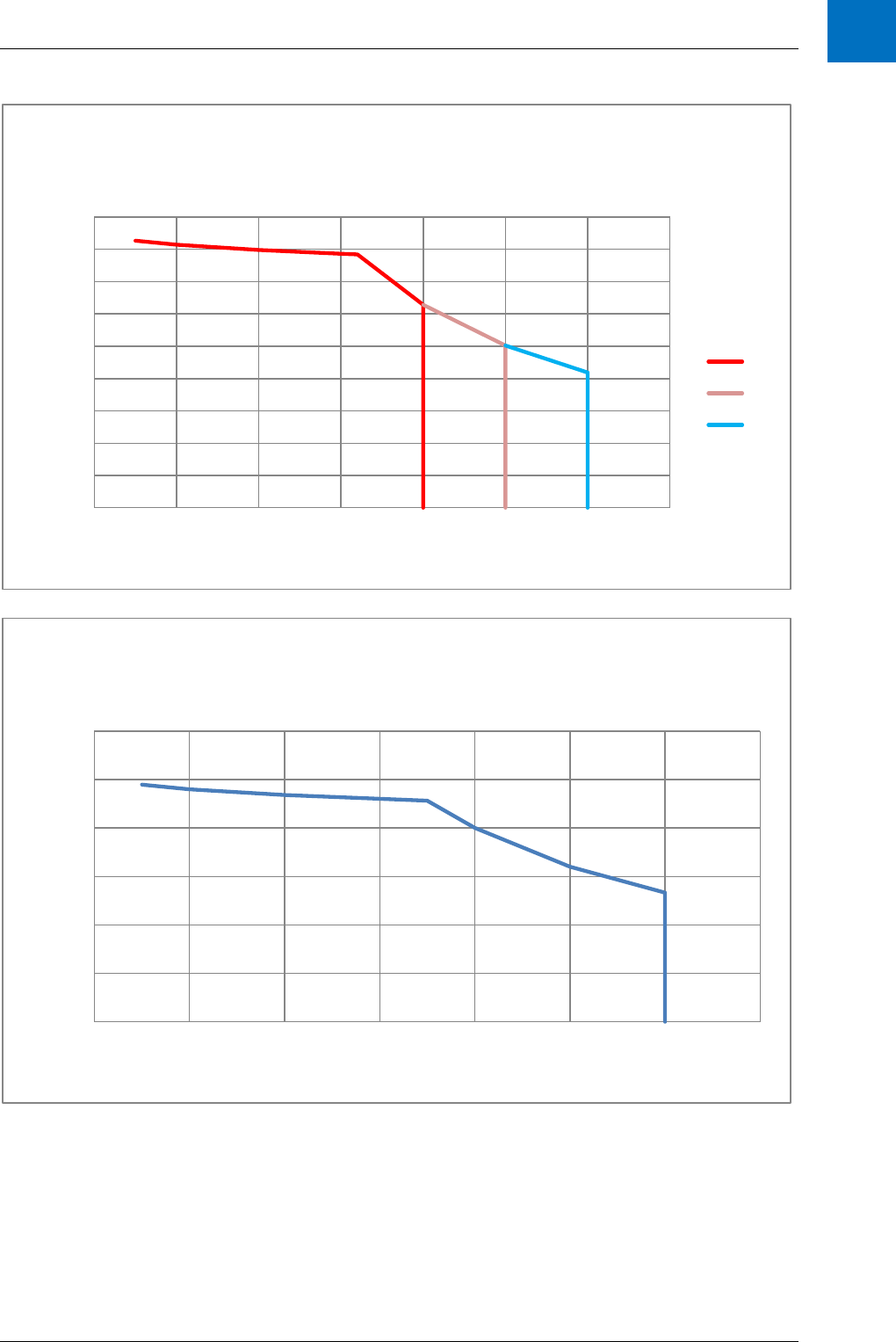
Technical Data
ANCA Motion D-000088 Rev 06 97
10
0
20
40
60
80
100
120
140
160
180
0 0.5 1 1.5 2 2.5 3 3.5
Vrms Motor (V line-line)
Irms Motor (A)
D2103 @200V Single-Phase Input with 10mH
Choke.
55C
50C
45C
0
20
40
60
80
100
120
0 0.5 1 1.5 2 2.5 3 3.5
Vrms Motor (V line-line)
Irms Motor (A)
D2103 @120V Single-Phase Input with 10mH
Choke.

AMD2000 Series D21xx Servo Drive - User Guide
98 D-000088 Rev 06 ANCA Motion
10.8.1.2 3-Phase
0
10
20
30
40
50
60
70
80
90
0 0.5 1 1.5 2 2.5 3 3.5
Vrms Motor (V line-line)
Irms Motor (A)
D2103 @100V Single-Phase Input with 10mH
Choke.
190
192
194
196
198
200
202
204
206
0 0.5 1 1.5 2 2.5 3 3.5
Vrms Motor (V line-line)
Irms Motor (A)
D2103 @240V Three-Phase Input with 3.06mH
Choke.
55C
50C
45C

Technical Data
ANCA Motion D-000088 Rev 06 99
10
170
172
174
176
178
180
182
184
186
188
0 0.5 1 1.5 2 2.5 3 3.5
Vrms Motor (V line-line)
Irms Motor (A)
D2103 @220V Three-Phase Input with 3.06mH
Choke.
55C
50C
45C
160
161
162
163
164
165
166
167
168
169
170
0 0.5 1 1.5 2 2.5 3 3.5
Vrms Motor (V line-line)
Irms Motor (A)
D2103 @200V Three-Phase Input with 3.06mH
Choke.
55C
50C
45C

AMD2000 Series D21xx Servo Drive - User Guide
100 D-000088 Rev 06 ANCA Motion
10.8.2 D2109 De-rating
10.8.2.1 1-Phase
0
50
100
150
200
250
0 1 2 3 4 5 6 7 8 9 10
Vrms Motor (V line-line)
Irms Motor (A)
D2109 @240V Single-Phase Input with 5.46mH
Choke.
0
20
40
60
80
100
120
140
160
180
200
0 1 2 3 4 5 6 7 8 9 10
Vrms Motor (V line-line)
Irms Motor (A)
D2109 @220V Single-Phase Input with 5.46mH
Choke.

Technical Data
ANCA Motion D-000088 Rev 06 101
10
0
20
40
60
80
100
120
140
160
180
0 1 2 3 4 5 6 7 8 9 10
Vrms Motor (V line-line)
Irms Motor (A)
D2109 @200V Single-Phase Input with 5.46mH
Choke.
0
20
40
60
80
100
120
0 1 2 3 4 5 6 7 8 9 10
Vrms Motor (V line-line)
Irms Motor (A)
D2109 @120V Single-Phase Input with 5.46mH
Choke.

AMD2000 Series D21xx Servo Drive - User Guide
102 D-000088 Rev 06 ANCA Motion
10.8.2.2 3-Phase
0
10
20
30
40
50
60
70
80
90
0 1 2 3 4 5 6 7 8 9 10
Vrms Motor (V line-line)
Irms Motor (A)
D2109 @100V Single-Phase Input with
5.46mH Choke.
180
185
190
195
200
205
0 1 2 3 4 5 6 7 8 9 10
Vrms Motor (V line-line)
Irms Motor (A)
D2109 @240V 3-Phase Input with 1.64mH 3-
phase Choke.

Technical Data
ANCA Motion D-000088 Rev 06 103
10
10.9 Regeneration Resistor
The D21xx drives have an inbuilt regeneration resistor. Regeneration refers to the process whereby when the
motor is actively providing energy to the drive and then stops, the kinetic energy in the entire mechanical system
connected to the shaft of the motor gets transferred to the bus capacitance in the drive, which increases the
voltage. This happens because of the motor inductance. When the voltage on the bus capacitance exceeds
385V the drive will connect the internal regeneration resistor in addition to any external regeneration resistor that
is provided by the user. The internal resistor is only capable of dissipating a power of 40W for the D2103 and
60W for the D2109. In addition to the power rating of the resistor to be observed the instantaneous energy
maximum for each resistor must also be observed. This is 24.7 joules for the D2103 drive and 143 joules for the
D2109. If there is more regeneration power than this is created then the user must connect an external resistor.
170
172
174
176
178
180
182
184
186
188
0 1 2 3 4 5 6 7 8 9 10
Vrms Motor (V line-line)
Irms Motor (A)
D2109 @220V 3-Phase Input with 1.64mH 3-
phase Choke.
155
157
159
161
163
165
167
169
171
0 1 2 3 4 5 6 7 8 9 10
Vrms Motor (V line-line)
Irms Motor (A)
D2109 @200V 3-Phase Input with 1.64mH 3-
phase Choke.

AMD2000 Series D21xx Servo Drive - User Guide
104 D-000088 Rev 06 ANCA Motion
In addition to the energy limitation and average power limitation of the regeneration resistors, the rate of
deceleration should not result in a DC Bus Overvoltage trip. This can occur if the instantaneous regenerated
power exceeds the power being dissipated by the regeneration resistor. This is rarely an issue but can be a
problem where very rapid decelerations at high retarding torques are desired. Consult ANCA Motion for advice if
this is a concern.
AMD2000
C
D
Internal Regeneration
Resistor:
40W(3A drive
/
60W (9A drive)
DC Bus Capacitors:
<400V,
440µF(3A drive)
/
1410µF/(9A drive)
External Regeneration
Resistor(s) as required
External Capacitor(s)
as required
X2B
10.9.1 Regeneration Resistor Selection, Regeneration Energy and Power
The starting points for the calculations regarding the required regeneration resistor are the two equations for
kinetic energy in the system, and are dependent entirely on the application of the user.
Linear:
Where E = Energy in Joules
m = mass in kg
v = velocity in m/s
Rotational:
Where E = energy in Joules
J = moment of inertia in kgm
2
ω = angular velocity in rad/s
Once the kinetic energy in the system is found, the voltage rise due to the energy on the bus
capacitance can be found:
Where V = voltage in V,
E = Energy in Joules,
C = Capacitance in Farads
The power dissipated in the regeneration resistor(s) additionally depends on how often the user is stopping the
torque output of the motor. For example, if the drive is operating in torque mode and a torque command is set to
0 from a non-0 value then the power dissipated is the kinetic energy in the system multiplied by the number of
times per second the drive is going from this set point to 0 again.

Technical Data
ANCA Motion D-000088 Rev 06 105
10
Example 1:
Servo Motor &
Pulley
Pulley Ratio = 5
Load (Grinding Wheel,
Flywheel etc.)
Pulley to Drive Load
The servo motor drives a load via two pulleys. The ratio is 1:5 from motor to load to provide a slower speed but
higher torque.
Assuming the belt has negligible stored energy compared to the rest of the system and the load is rotational:
J
eff
(effective moment of inertia) = J
motor
+J
motor pulley
+
(J
load pulley
+ J
load
)
The energy stored in the system at the time the torque set point is reduced to zero is:
(For the inbuilt brake resistors, this value must not exceed 24.7Joules for D2103 drive and 143 Joules for D2109
drive.)
The rise in voltage in this example is then
Example 2:
The situation in example 1 has torque applied and then stopped twice per second. The power required for the
regeneration resistor to dissipate all of the energy is
10.10 Materials
Drive enclosure
The AMD2000 Drive chassis (main, sub, and fan) are stainless steel 304 with a silver
paint finish. The AMD2000 Drive heat-sink is aluminium 6063 T5. The AMD2000
face cover main and PN panels are SABIC Resin 221R with a print finish on the main
panel.
Packaging
Cardboard
Disposal
The drive contains raw materials that should be recycled to preserve energy and
natural resources. The package materials are mostly environmentally compatible and
recyclable. All metal parts can be recycled. The plastic parts can either be recycled
or burned under controlled circumstances, according to local regulations. Most
recyclable parts are marked with recycling marks. The electrolytic capacitors and the
integrated power module are classified as hazardous waste within the EU and must
be removed and handled according to local regulations. For further information on
environmental aspects and more detailed recycling instructions, please contact your
local ANCA Motion distributor.

AMD2000 Series D21xx Servo Drive - User Guide
106 D-000088 Rev 06 ANCA Motion
10.11 Standards Conformity
Marking & Applicable
Regulations
Standard
Certification
Organisation
Drive
D2103
D2109
EC Type Examination
Cert has been issued
by Projects etc. Pty
Ltd, as a Notified
Body (2241) for the
EU Machinery
Directive
No.
141006GRa
dated
06/10/2014
No.
141006GRa
dated
06/10/2014
EC Machinery
Directive 2006
/42/EC (Annex
IIA)
EN 61800-5-1: 2007
(Class I)
EC
Electromagnetic
Compatibility
2004/108/EC
(Annex IV)
EN 61800-5-2: 2007
EN 61800-3: 2004
(Category C3)
17
ETG 1000 series
ETG 9001
ETG 1300
Note: the AMD2000 is a
conforming EtherCAT
device, but does not
qualify as conformance
tested. ANCA Motion
self-determination of
compliance.
Those items in the drive
with no applicable
regulation, but to which
standards have been
applied.
Servo Profile over EtherCAT
fieldbus profile (SoE). IEC
61800-7.
IEC 61491, for serial data link
real time communications in
industrial machines.
ANCA Motion self-
determination of
compliance within
certain limits.
17
EtherCAT® is a registered trademark and patented technology, licensed by Beckhoff Automation GmbH, Germany

Technical Data
ANCA Motion D-000088 Rev 06 107
10
10.11.1 CE Declaration of Conformity
EC DECLARATION OF CONFORMITY
Manufacturer:
ANCA Motion Pty. Ltd.
1 Bessemer Road
Bayswater North
Victoria 3153
Australia
Person Authorised to
Compile the Technical File,
and ANCA Motion’s
Authorised Representative
in the EU (contract No. am-
1000141, 29/08/2014):
Mr. Jan Langfelder
ANCA GmbH
Aloise-Senefelder-Str.
4 68167 Mannheim,
Germany
Phone: +49 6213381012
In accordance with the following directives:
EC Machinery Directive 2006/42/EC (Annex IIA)
EC Electromagnetic Compatibility 2004/108/EC (Annex IV)
Herewith declare that the D2103 and D2109 servo drives of the AMD2000 series, when used in accordance with
the manufacturer’s instructions, conforms to the essential health and safety requirements of the Machinery
Directive and conforms to the protection requirements of the EMC Directive by virtue of its design, construction
and assessment. In support of this declaration the D2103 and D2109 servo drives have been evaluated as
complying with the following harmonized standards and all appropriate associated standards:
Standard
Title
Ed./Date
EN 61800-5-2
International Standard for Adjustable Speed Electrical Power Drive
Systems, Part 5-2: Safety Requirements – Functional
1st, 2007
EN 61800-5-1
International Standard for Adjustable Speed Electrical Power Drive
Systems, Part 5-1: Safety Requirements – Electrical, thermal and energy
2nd, 2007
EN 61800-3
International Standard for Adjustable Speed Electrical Power Drive
Systems, Part 3: EMC requirements and specific test methods
2nd, 2004
Such servo drives are suitable for use in machinery level applications seeking to independently certify to comply
with MD and EMC D requirements via;
Standard
Title
Date
IEC 62061
Safety of machinery – Functional safety of safety-related electrical,
electronic and programmable electronic control systems
2005
EN ISO 13849-1
Safety of machinery – Safety related parts of control systems –General
Principles for design
2008
An EC Type Examination Cert (No. 141006GRa dated 06/10/2014) has been issued by Projects etc Pty Ltd, as a
Notified Body (2241) for the EU Machinery Directive.
The Technical File for the Machinery Directive Compliance with 2006/42/EC is numbered D-000093, and dated
02/10/2014 Revision 01, and is held by the manufacturer.
The Technical Documentation for the EMC Compliance with 2004/108/EC is numbered D-000092, and dated
02/10/2014 Revision 01, and is held by the manufacturer.

AMD2000 Series D21xx Servo Drive - User Guide
108 D-000088 Rev 06 ANCA Motion
10.11.1.1 Safety Function Specifications (EN 61800-5-2 and associated)
The object of this standard (61800-5-2) is to specify requirements for adjustable speed Power Drive Systems
(PDS) or their elements with respect to functional safety considerations. The D2103 and D2109 incorporate a
Safe Torque Off function, and comply with the standard with the following provisions:
1. The drives are installed and maintained according to the instructions given in the user guide.
Function
PFHd
(dangerous failures per hour)
SIL (62061)
PL (13849-1)
Proof Test Interval
Safe
Torque Off
6.84E-9
3
e
10 years continuous use
10.11.1.2 Electrical Safety Specifications (EN 61800-5-1 and associated)
The object of this standard (61800-5-1) is to specify requirements for adjustable speed Power Drive Systems
(PDS) or their elements with respect to electrical, thermal and energy safety considerations. The D2103 and
D2109 are considered to be protective Class I PDS, and comply with the standard with the following provisions
1. The drives are installed and maintained according to the instructions given in the user guide.
10.11.1.3 EMC Specifications (EN 61800-3 and associated)
The object of this standard (61800-3) is to define the limits and test methods for a Power Drive System (PDS)
according to its intended use, whether residential, commercial or industrial. The standard sets out immunity
requirements and requirements for electromagnetic emissions as minimums within these different environments.
The D2103 and D2109 are intended for use as Category 3 PDS, and have been tested and certified to comply
for use within what 61800-3 defines as the second environment. The D2103 and D2109 comply with the
standard with the following provisions:
1. The motor and control cables are selected according the specifications given in the user guide.
2. The drives are installed and maintained according to the instructions given in the user guide.
3. The maximum cable lengths are 15 metres.
Warning: A drive of category C3 is not intended to be used on a low-voltage public network which
supplies domestic premises. Radio frequency interference is expected if the drive is used on such a
network.
10.11.1.4 Definitions
First environment
Environment that includes domestic premises, it also includes
establishments directly connected without intermediate transformers to a
low-voltage power supply network which supplies buildings used for
domestic purposes.
Second environment
Environment that includes all establishments other than those directly
connected to a low-voltage power supply network which supplies buildings
used for domestic purposes.
Category C3 Power Drive System
Category 3 is for a PDS of rated voltage less than 1000 V, intended for
use in the second environment and not intended for use in the first
environment.
Protective Class I
Equipment in which protection against electric shock does not rely on
basic insulation only, but which includes an additional safety precaution in
such a way that means are provided for the connection of accessible
conductive parts to the protective (earthing) conductor in the fixed wiring
of the installation, so that accessible conductive parts cannot become live
in the event of a failure in the basic insulation.

Technical Data
ANCA Motion D-000088 Rev 06 109
10
10.11.2 EtherCAT®
18
Conformance Marking
An EtherCAT device conformance mark is attached to each drive in order to verify that the unit has been tested
for compliance with the EtherCAT marking, indicator and performance guidelines covered by the ETG standards
listed in section 10.11 Standards Conformity. Future drive revisions intend to achieve “Conformance tested”
marking by independent verification through an externally registered body.
18
EtherCAT® is a registered trademark and patented technology, licensed by Beckhoff Automation GmbH, Germany

AMD2000 Series D21xx Servo Drive - User Guide
110 D-000088 Rev 06 ANCA Motion
11 Accessories
11.1 What this Chapter Contains
This chapter contains summarized information on accessories options available for this drive
- Ordering Information / Catalogue Number Interpretation
- Details of Accessories
For additional details, please refer to full catalogue and information available via 12.3 Product, Sales and Service
Enquiries
11.2 Motors
11.2.1 Motor Catalogue Number Interpretation
Product
M: Motor
Series
A: Alpha Series
Frame Size
60: 60 mm square flange
80: 80 mm square flange
86: 86 mm square flange
130: 130 mm square flange
Rated Torque
06: 0.6 Nm
13: 1.3 Nm
24: 2.4 Nm
.. etc
Rated Speed
10: 1000 rpm
20: 2000 rpm
30: 3000 rpm
Refer to catalogue for full list
Options
B: Brake
Feedback Type
A: Incremental Digital
M A 6 0 - 0 6 3 0 - A B

Accessories
ANCA Motion D-000088 Rev 06 111
11
11.2.2 Motor Electrical Information Summary
Order code
Rated Torque
(Nm)
Rated Speed
(rpm)
Rated Power
(W)
Rated Current
(A)
Torque
Constant
(Nm/A)
Voltage
Constant
(V/krpm)
Max Current
(A)
Max Speed
300 VDC bus
(rpm)
Rotor Inertia
(kg.cm2)
Stator
Resistance
(Ohm)
Stator
Inductance
(mH)
Motor Poles
AMD2000
D2103
MA60-630-A
0.64
3000
200
1.8
0.39
33
5.4
7000
0.17
7.5
16.2
8
MA60-630-AB
0.64
3000
200
1.8
0.39
33
5.4
7000
0.22
7.5
16.2
8
MA60-1330-A
1.27
3000
400
2.5
0.51
49.89
7.5
5000
0.28
5.6
14.5
8
MA60-1330-AB
1.27
3000
400
2.5
0.51
49.89
7.5
5000
0.33
5.6
14.5
8
MA86-2430-A
2.39
3000
750
3.4
0.78
54.3
10.2
5000
2.45
2.18
7.7
8
MA86-2430-AB
2.39
3000
750
3.4
0.78
54.3
10.2
5000
2.58
2.18
7.7
8
MA130-5310-A
5.25
1000
550
3.43
1.68
117.3
10.3
2000
6.26
3.58
18.33
8
MA130-5310-AB
5.25
1000
550
3.43
1.68
117.3
10.3
2000
6.58
3.58
18.33
8
AMD2000
D2109
MA80-2430-A
2.39
3000
750
4.3
0.61
52.09
12.9
5000
0.94
2.1
8.63
8
MA80-2430-AB
2.39
3000
750
4.3
0.61
52.09
12.9
5000
1.07
2.1
8.63
8
MA130-4830-A
4.78
3000
1500
7.06
0.74
51.7
21.2
5000
6.26
0.65
3.58
8
MA130-4830-AB
4.78
3000
1500
7.06
0.74
51.7
21.2
5000
6.58
0.65
3.58
8
MA130-7220-A
7.16
2000
1500
7.57
1.06
72.5
22.71
4000
8.88
0.79
4.74
8
MA130-7220-AB
7.16
2000
1500
7.57
1.06
72.5
22.71
4000
9.20
0.79
4.74
8
MA130-9620-A
9.55
2000
2000
9.18
1.14
79.6
27.5
3500
12.14
0.58
3.78
8
MA130-9620-AB
9.55
2000
2000
9.18
1.14
79.6
27.5
3500
12.46
0.58
3.78
8
11.2.3 Brake Motor Specific Information
Order Code
Brake
Current (A)
Brake
Active
Time (ms)
Brake
Release
Time
(ms)
Weight (kg)
Rotor
Inertia
(kg/cm
2
)
Static
Friction
Torque
(Nm)
Connector
Type
MA60-1330-AB
0.262
17
32
0.4
0.049
2
N
MA86-2430-AB
0.43
35
25
0.65
0.129
3
N
MA130-5310-AB
0.816
27
76
1.1
0.324
20
C
MA80-2430-AB
0.43
35
25
0.65
0.129
3
N
MA130-4830-AB
0.816
27
76
1.1
0.324
20
C
MA130-7220-AB
0.816
27
76
1.1
0.324
20
C
MA130-9620-AB
0.816
27
76
1.1
0.324
20
C
N: Flying Lead (no connector) C: MS Connector

AMD2000 Series D21xx Servo Drive - User Guide
112 D-000088 Rev 06 ANCA Motion
11.2.4 Motor Mechanical Information Summary
A E
C
D
F
H
B
B
G
G
Order code
A (mm)
B (mm)
C (mm)
D (mm)
E (mm)
F (mm)
G (mm)
H (mm)
Weight (kg)
IP Rating*
19
Insulation
Grade
Connector
Style
MA60-0630-A
112.8
60
50
14
30
27
70
5.5
1.03
IP67
F (155)
AMP
MA60-0630-AB
147.3
60
50
14
30
27
70
5.5
1.43
IP67
F (155)
AMP
MA60-1330-A
132.8
60
50
14
30
27
70
5.5
1.37
IP67
F (155)
AMP
AMD2000
MA60-1330-AB
167.3
60
50
14
30
27
70
5.5
1.77
IP67
F (155)
AMP
D2103
MA86-2430-A
148
86
80
16
35
32
100
6.5
3.41
IP67
F (155)
AMP
MA86-2430-AB
183.2
86
80
16
35
32
100
6.5
4.06
IP67
F (155)
AMP
MA130-5310-A
164.8
130.4
110
22
58
52
145
9
6.47
IP67
B (130)
MS
MA130-5310-AB
219.3
130.4
110
22
58
52
145
9
7.57
IP67
B (130)
MS
MA80-2430-A
139
80
70
19
40
37
90
5.5
2.47
IP67
F (155)
AMP
MA80-2430-AB
174
80
70
19
40
37
90
5.5
3.12
IP67
F (155)
AMP
MA130-4830-A
164.8
130.4
110
22
58
52
145
9
6.47
IP67
B (130)
MS
AMD2000
MA130-4830-AB
219.3
130.4
110
22
58
52
145
9
7.57
IP67
B (130)
MS
D2109
MA130-7220-A
183.8
130.4
110
22
58
52
145
9
8.08
IP67
B (130)
MS
MA130-7220-AB
238.3
130.4
110
22
58
52
145
9
9.18
IP67
B (130)
MS
MA130-9620-A
214.8
130.4
110
22
58
52
145
9
10.18
IP67
B (130)
MS
MA130-9620-AB
269.3
130.4
110
22
58
52
145
9
11.28
IP67
B (130)
MS
19
IP rating excludes electrical connector and shaft

Accessories
ANCA Motion D-000088 Rev 06 113
11
11.3 Cables
11.3.1 Cable Catalogue Number Interpretation
K2B-S4MD-020
K:Cable
Servo Drive Series:
2:AMD2000
5:AMD5x
Motor family:
A:Alpha Series
B:Beta Series
L:LinX
Function:
F:Feedback
A:Armature
B:Armature with Brake
T:Armature with Temperature
S:Armature with Temp & Brake
Cable Type:
Available options:
S,U,O,2,4
Connector Type:
P: Plastic
M:Metal
Special options:
D: Default
Length:
Examples:
002: 0.2 Metre
015: 1.5 Metres
030: 3 Metres
Function Cable type Description
F S Feedback cable shielded incremental
A/B/T/S 0 Armature cable shielded 0.75mm2
A/B/T/S S Armature cable shielded 1.5mm2
A/B/T/S U Armature cable unshielded
A/B/T/S 2 Armature cable shielded 2.5mm2
A/B/T/S 4 Armature cable shielded 4mm2

AMD2000 Series D21xx Servo Drive - User Guide
114 D-000088 Rev 06 ANCA Motion
11.3.2 Encoder Cables
11.3.2.1 Encoder Cables (Plastic/AMP)
Catalogue Number
Length
K2A-FSPD-020
2m
K2A-FSPD-030
3m
K2A-FSPD-050
5m
K2A-FSPD-100
10m
11.3.2.2 Encoder Cables (Metal/MS)
Catalogue Number
Length
K2A-FSMD-020
2m
K2A-FSMD-030
3m
K2A-FSMD-050
5m
K2A-FSMD-100
10m
11.3.2.3 Encoder Splitter Cable
Part Number
Length
619-0-01-0340
0.55m
11.3.3 Armature Cables
11.3.3.1 Shielded Armature Cables (Plastic/AMP)
Catalogue Number
Length
K2A-ASPD-020
2m
K2A-ASPD-030
3m
K2A-ASPD-050
5m
K2A-ASPD-100
10m
11.3.3.2 Shielded Armature Cables (Metal/MS)
Catalogue Number
Length
K2A-ASMD-020
2m
K2A-ASMD-030
3m

Accessories
ANCA Motion D-000088 Rev 06 115
11
K2A-ASMD-050
5m
K2A-ASMD-100
10m
11.3.3.3 Shielded Armature Cables with Brake (Metal/MS)
Catalogue Number
Length
K2A-BSMD-020
2m
K2A-BSMD-030
3m
K2A-BSMD-050
5m
K2A-BSMD-100
10m

AMD2000 Series D21xx Servo Drive - User Guide
116 D-000088 Rev 06 ANCA Motion
11.4 Other Accessories
11.4.1 I/O Interface Cable
Part Number
Description
ICN-1026-1190
AMD2000 I/O Interface Cable
11.4.2 I/O Interface Module
Part Number
Description
ICN-3077-1150
AMD2000 I/O Interface Module – I/O as described in 7 Control Wiring
646-0-05-0723
AMD2000 I/O Interface Module with single-ended to differential inputs conversion
on DI09 and DI10 – refer to 7.3.2.2.3 for detailed operation
11.4.3 I/O Interface Module Kit
Part Number
Description
619-0-00-0965
AMD2000 I/O Interface Module Kit
ICN-3077-1150
1 x AMD2000 I/O Interface Module
ICN-1026-1190
1 x AMD2000 I/O Interface Cable

Accessories
ANCA Motion D-000088 Rev 06 117
11
11.4.4 I/O Connector
Part Number
Description
619-0-00-1187
AMD2000 I/O Connector
ICN-3077-1652
Plug, MDR 50 Way Male, Solder, Shielded
ICN-3077-1653
Backshell, MDR 50 Way, Screw Type
Warning: The IO Connector supplied in this way is not guaranteed by ANCA Motion for reliable STO
delivery. Correct wiring and controls on manufacture of the cabling integrated with this connector will be
necessary and must form part of the installer’s own safety system requirements.
11.4.5 D21xx STO Override Plug
Part Number
Description
619-0-00-1285
D21xx STO Override Plug
Warning: The STO Override Plug de-asserts STO, allowing the drive to operate normally without safe
system interference. Care should be exercised by installers and maintainers where machines are
intended to operate safely using STO, as this device may be used to unintentionally override the STO
function.
11.4.6 EtherCAT Cables
Product code
KXE-1100-0020
Connector type:
1 – RJ45 +RJ45
Reserved
Cable type:
1 – CAT5e PVC SF/UTP
Cable length:
Examples:
0002: 0.2 Metre
0015: 1.5 Metres
0030: 3.0 Metres
EtherCAT cable
Examples
Catalogue Number
Description
KXE-1100-0002
Ethernet Cable, Cat 5e, SF/UTP, 0.2m
KXE-1100-0015
Ethernet Cable, Cat 5e, SF/UTP, 1.5m
KXE-1100-0030
Ethernet Cable, Cat 5e, SF/UTP, 3.0m

AMD2000 Series D21xx Servo Drive - User Guide
118 D-000088 Rev 06 ANCA Motion
11.4.7 Armature Cable Shield Termination Kit
Part Number
Description
619-0-02-0957
AM2000 9A (D2109) Armature Cable Shield Termination Kit
619-0-00-1028
AM2000 3A (D2103) Armature Cable Shield Termination Kit
11.4.8 EMI Filters
Part Number
Description
ICN-3096-1665
Schaffner FN 3270H-10-44
ICN-3096-1667
Schaffner FN 3270H-20-44
ICN-3096-1676
Schaffner FN 350-8-29
ICN-3096-1674
Schaffner FN 350-20-29
11.4.9 Line Reactors
Part Number
Description
ICN-3096-1670
Hammond Power Solutions CRX07D6AC
ICN-3096-1671
Hammond Power Solutions CRX0014AC
ICN-3096-1672
Hammond Power Solutions CRX0014BC
11.4.10 DC Chokes
Part Number
Description
ICN-3096-1661
Hammond Manufacturing 159ZJ

Accessories
ANCA Motion D-000088 Rev 06 119
11
11.5 Starter Kits
11.5.1 D2103 SoE Starter Kit
Part Number
Description
619-1-xx-0971
D2103 SoE Starter Kit
D2103-2S2-A
D2103 SoE Servo Drive
MA60-0630-A
Alpha Series Servo Motor
K2A-FSPD-020
Alpha Motor Cable
K2A-ASPD-020
Alpha Motor Cable
ICN-1026-1097
Ethernet Cable, Cat 5e, SF/UTP, 1m
11.5.2 D2109 SoE Starter Kit
Part Number
Description
619-1-xx-0972
D2109 SoE Starter Kit
D2109-2S2-A
D2109 SoE Servo Drive
MA80-2430-A
Alpha Series Servo Motor
K2A-FSPD-020
Alpha Motor Cable
K2A-ASPD-020
Alpha Motor Cable
ICN-1026-1097
Ethernet Cable, Cat 5e, SF/UTP, 1m
11.5.3 D2103 CoE Starter Kit
Part Number
Description
619-2-xx-0971
D2103 CoE Starter Kit
D2103-2C2-A
D2103 CoE Servo Drive
MA60-0630-A
Alpha Series Servo Motor
K2A-FSPD-020
Alpha Motor Cable
K2A-ASPD-020
Alpha Motor Cable
ICN-1026-1097
Ethernet Cable, Cat 5e, SF/UTP, 1m

AMD2000 Series D21xx Servo Drive - User Guide
120 D-000088 Rev 06 ANCA Motion
11.5.4 D2109 CoE Starter Kit
Part Number
Description
619-2-xx-0972
D2109 CoE Starter Kit
D2109-2C2-A
D2109 CoE Servo Drive
MA80-2430-A
Alpha Series Servo Motor
K2A-FSPD-020
Alpha Motor Cable
K2A-ASPD-020
Alpha Motor Cable
ICN-1026-1097
Ethernet Cable, Cat 5e, SF/UTP, 1m
Note: To use any of the STO Starter Kits you will additionally need to order one of these connection options:
1. 619-0-00-0965 – AMD2000 I/O Interface Module Kit
2. 619-0-00-1187 – AMD2000 I/O Connector
Warning: The IO Interface Module Kit is guaranteed for reliable STO operation and has been certified as
part of AM’s STO Safety Function CE certification procedure. The installer must connect their own
external safety system to the interface module according to the appropriate safety standards.
Warning: The IO Connector is not guaranteed for reliable STO operation as the IO needs to be suitably
manufactured with cabling/wiring and tested for reliability. It is the responsibility of the installer to ensure
that IO Connector and attached cabling/wiring is reliable as part of the installer’s own safety system
requirements.

Additional Information
ANCA Motion D-000088 Rev 06 121
12
12 Additional Information
12.1 What this Chapter Contains
This chapter contains information on product support and feedback:
- Maintenance and repairs
- Contact information
- Feedback on the user guide
12.2 Maintenance and Repairs
DANGER HIGH VOLTAGE - The working DC bus is live at all times when power is on. The Main Isolator
feeding the drive must be switched to the Off position at least 15 minutes before any work is commenced
on the unit. The operator must check the bus voltage with a tested working voltage measuring instrument
prior to disconnecting any connectors or opening the DC Bus terminal cover. The red LED indicator on the
front of the drive which indicates that there is charge remaining in the drive is only to be used as an aid to
visual troubleshooting. It shall not be relied on as a means of safety.
There are no user serviceable parts inside the AMD2000 drive; therefore maintenance only involves inspection of
the drive its connections and enclosure. Make sure that all connections are fitted correctly and that there are no
signs of damage. Check that all wires are tightly fitted to the connectors and that there are no signs of
discolouration which may indicate heating. Make sure all drive covers are securely fitted and that they have no
signs of damage. Make sure that the drive enclosure is free from dust or anything that may inhibit its operation.
Refer to section 4 Mechanical Installation for site requirements, tools, and installation and uninstallation
information.
There are no internal adjustments inside the AMD2000. For any repairs please contact our nearest office or
agent. Refer to section 12.3 Product, Sales and Service Enquiries.
12.3 Product, Sales and Service Enquiries
If you require assistance for installation, training or other customer support issues, please contact the closest
ANCA Motion Customer Service Office in your area for details.
12.4 Feedback
This user guide is based on information available at the time of publication. Reasonable precautions have been
taken in the preparation of this user guide, but the information contained herein does not purport to cover all
details or variations in hardware and software configuration. Features may be described herein which are not
present in all hardware and software systems. We would like to hear your feedback via our website:
www.ancamotion.com/Contact-Us
ANCA Motion Pty. Ltd.
1 Bessemer Road
Bayswater North
VIC 3153
AUSTRALIA
Telephone: +61 3 9751 8900
Fax: +61 3 9751 8901
www.ancamotion.com/Contact-Us
Email: [email protected]
ANCA Motion Taiwan
1F, No.57, 37 Road
Taichung Industrial Park
Taichung 407
TAIWAN
Telephone: +886 4 2359 0082
Fax: +886 4 2359 0067
www.ancamotion.com/Contact-Us
Email: [email protected]
