
DOT HS 812 360 December 2016
Human Factors Design Guidance
For Driver-Vehicle Interfaces
Disclaimer
This publication is distributed by the U.S. Department of
Transportation, National Highway Traffic Safety Administration, in
the interest of information exchange. The opinions, findings, and
conclusions expressed in this publication are those of the authors and
not necessarily those of the Department of Transportation or the
National Highway Traffic Safety Administration. The United States
Government assumes no liability for its contents or use thereof. If
trade or manufacturers’ names or products are mentioned, it is
because they are considered essential to the object of the publication
and should not be construed as an endorsement. The United States
Government does not endorse products or manufacturers.
Suggested APA Format Citation:
Campbell, J. L., Brown. J. L., Graving, J. S., Richard, C. M., Lichty, M. G., Sanquist, T., … & Morgan, J.
L.. (2016, December). Human factors design guidance for driver-vehicle interfaces (Report No.
DOT HS 812 360). Washington, DC: National Highway Traffic Safety Administration.

i
REPORT DOCUMENTATION PAGE
Form Approved
OMB No. 0704-0188
1. AGENCY USE ONLY (Leave blank)
2. REPORT DATE
December 2016
3. REPORT TYPE AND DATES
COVERED
4. TITLE AND SUBTITLE
Human Factors Design Guidance for Driver-Vehicle Interfaces
5. FUNDING NUMBERS
Contract No. DTN22-11-00236/001
6. AUTHORS
John L. Campbell, James L. Brown. Justin S. Graving, Christian M. Richard,
Monica G. Lichty, Thomas Sanquist, L. Paige Bacon, Robert Woods, Hong Li,
Diane N. Williams, Justin F. Morgan
7. PERFORMING ORGANIZATION NAME AND ADDRESS
Battelle Memorial Institute
505 King Avenue
Columbus, Ohio 43201-2696
8. PERFORMING ORGANIZATION
REPORT NUMBER
DOT HS 812 360
9. SPONSORING/MONITORING AGENCY NAME AND ADDRESS
. SNational Highway Traffic Safety Administration
1200 New Jersey Avenue SE.
Washington, DC 20590
10. SPONSORING/MONITORING
AGENCY REPORT NUMBER
11. SUPPLEMENTARY NOTES
Christian Jerome was NHTSA’s Contracting Officer’s Representative (COR) for this effort.
12a. DISTRIBUTION/AVAILABILITY STATEMENT
Document is available to the public from the National Technical Information Service
www.ntis.gov
12b. DISTRIBUTION CODE
13. ABSTRACT (Maximum 200 words)
This document provides human factors design guidance for driver-vehicle interfaces (DVIs). The guidance provided is based on the
findings of current high-quality research (including both the best-available scientific literature and current research being conducted
by agencies of the United States Department of Transportation), as well as basic human factors concepts. The design guidance is
provided as a complementary resource to other documents and resources, as well as an augment to industry research and existing
guidance from the National Highway Traffic Safety Administration. The information in this document may be useful to researchers,
designers, and original equipment manufacturers and Tier-1 suppliers seeking to ensure the compatibility of DVIs with driver
limitations and capabilities.
14. SUBJECT TERMS
Driver Vehicle Interface, DVI, Crash Warnings, Driver Performance; Heavy Vehicle
15. NUMBER OF PAGES
260
16. PRICE CODE
17. SECURITY CLASSIFICATION OF
REPORT
Unclassified
18. SECURITY CLASSIFICATION OF
THIS PAGE
Unclassified
19. SECURITY
CLASSIFICATION
OF ABSTRACT
20. LIMITATION OF
ABSTRACT
ii
Table of Contents
Chapter 1. Introduction ....................................................................................................... 1-1
Background ...................................................................................................................... 1-1
Scope ............................................................................................................................... 1-2
Objectives ........................................................................................................................ 1-2
Organization of this Document ......................................................................................... 1-2
Chapter 2. How to Use This Document .............................................................................. 2-1
Two-Page Format ............................................................................................................. 2-1
The Left-Hand Page ......................................................................................................... 2-1
The Right-Hand Page ...................................................................................................... 2-2
Use of Acronyms .............................................................................................................. 2-3
Chapter 3. General DVI Considerations ............................................................................. 3-1
Distraction ........................................................................................................................ 3-2
General Workload Considerations .................................................................................... 3-4
Workload from Secondary Tasks ...................................................................................... 3-6
Providing Drivers With Information on System Function and System Messages............... 3-8
Developing Driver Training Material ................................................................................ 3-10
Chapter 4. Design Guidance for Safety Messages ............................................................ 4-1
Multimodal Warning Messages ......................................................................................... 4-4
Warning Stages ................................................................................................................ 4-6
Providing Forward Collision Warnings That Accommodate Driver Brake
Reaction Time .......................................................................................................... 4-8
Using Coverage Zones to Provide Lane Change Information ......................................... 4-10
Chapter 5. Message Characteristics
.................................................................................. 5-1
Message Complexity ........................................................................................................ 5-4
Selection of Sensory Modality .......................................................................................... 5-6
Chapter 6. Visual Interfaces................................................................................................ 6-1
Visual Display Type for Safety-Related Messages ........................................................... 6-2
Locating a Visual Display ................................................................................................. 6-4
Using Color ...................................................................................................................... 6-6
Selecting Character Height for Icons and Text ................................................................. 6-8
Characteristics of Legible Text ....................................................................................... 6-10
Temporal Characteristics of Visual Displays ................................................................... 6-12
Display Glare .................................................................................................................. 6-14
Head-up Displays ........................................................................................................... 6-16
Chapter 7. Auditory Interfaces ........................................................................................... 7-1
Auditory Display Type....................................................................................................... 7-2
Perceived Urgency of Auditory Warnings ......................................................................... 7-4
Perceived Annoyance of Auditory Warnings ..................................................................... 7-6
Loudness of Auditory Warning Signals ............................................................................. 7-8
Distinctiveness of Warning Messages ............................................................................ 7-10
iii
Using Localization Cues to Indicate Direction .................................................................. 7-12
Presenting Warnings Using Speech Messages ............................................................... 7-14
Chapter 8. Haptic Interfaces ................................................................................................8-1
Selecting a Haptic Display .................................................................................................8-2
General Characteristics for Haptic Displays ......................................................................8-4
Improving Distinctiveness of Haptic Displays ....................................................................8-6
Accommodating for Vibrotactile Sensitivity Across the Body .............................................8-8
Generating a Detectable Signal in a Vibrotactile Seat ..................................................... 8-10
Presenting Spatial Information Using a Vibrotactile Seat ................................................. 8-12
Chapter 9. Driver Inputs.......................................................................................................9-1
General Guidance for Driver-DVI Interactions ...................................................................9-2
Control Placement.............................................................................................................9-4
Selecting Physical Control Type ........................................................................................9-6
Control-movement Compatibility .......................................................................................9-8
Control Coding ................................................................................................................ 9-10
Labels for Controls .......................................................................................................... 9-12
Voice Recognition Inputs................................................................................................. 9-14
Chapter 10. System Integration........................................................................................... 10-1
Prioritizing Messages Presented to Drivers ..................................................................... 10-2
Using “Master” Warnings in Integrated Warning Systems ............................................... 10-4
Overview of the HFCV Integration Architecture ............................................................... 10-6
Chapter 11. Application of Human Factors Design Guidance to
Heavy Vehicle DVIs ............................................................................................... 11-1
Design Considerations for Warning Signals in Heavy Vehicles ....................................... 11-2
Selection of Sensory Modality for Heavy Vehicle Warnings ............................................. 11-4
Design Guidance for Visual Displays in Heavy Vehicles ................................................. 11-6
Visual Display Location in Heavy Vehicles ...................................................................... 11-8
Design Guidance for Auditory Displays in Heavy Vehicles ............................................ 11-10
Design Guidance for Haptic Displays in Heavy Vehicles ............................................... 11-12
Driver Controls for Collision Warning Systems in Heavy Vehicles ................................. 11-14
General DVI Considerations for Heavy Vehicles ........................................................... 11-16
Chapter 12. Tutorials ........................................................................................................... 12-1
Tutorial 1: Procedures for Assessing Driver Performance: Visual Demand
Measurements ......................................................................................................... 12-2
Tutorial 2: Priority Order Index Look-Up Table for Message Prioritization ..................... 12-19
Tutorial 3: Preliminary HFCV Integration Architecture ................................................... 12-21
Tutorial 4: Heavy Vehicle Characteristics and Driving Environment Relevant to
DVI Design ............................................................................................................ 12-56
iv
Chapter 13. Glossary .......................................................................................................... 13-1
Chapter 14. Index ................................................................................................................ 14-1
Chapter 15. Abbreviations .................................................................................................. 15-1
Chapter 16. Equations......................................................................................................... 16-1
Chapter 17. Relevant Documents From the United States Department of
Transportation, SAE International, and International
Organization for Standardization ......................................................................... 17-1
Chapter 18. References ....................................................................................................... 18-1

INTRODUCTION DVI DESIGN GUIDANCE
1-1
Chapter 1. Introduction
Background
Considerable progress has been made toward reducing the incidence of property loss, injuries, and
fatalities on the Nation’s highways. However, motor vehicle crashes continue to impose a heavy
toll upon road users. The National Highway Traffic Safety Administration reports that in 2012
there were approximately 5,615,000 police-reported motor vehicle crashes resulting in
approximately 23,000 people killed (with a fatality rate of 1.13 fatalities per 100 million vehicle
miles traveled) and approximately 2.1 million injured (NHTSA, 2014).
A number of active safety systems exist or are in development that may address these crashes.
Technologies such as forward collision warning (FCW) are being implemented in an increasingly
large number of new vehicles. Research from the United States Department of Transportation and
industry examining such technologies is helping to develop an information backbone for the
surface transportation system that will support applications to enhance safety, mobility, and
sustainability. However, these promising applications, no matter the source of information that
causes them to activate, present a unique set of challenges for designers of driver-vehicle
interfaces (DVIs).
These advanced safety technologies produce a large amount of information. Sometimes, the
information may be complex (e.g., warning of a vehicle in a blind spot prior to a lane change, or
providing notification of an upcoming hazard). In some cases, this complex information may need
to be provided to, comprehended, and rapidly acted upon by the driver to avoid a collision. Thus,
ensuring that the DVI enables drivers to quickly and easily access needed information is of great
importance with respect to driver performance.
The purpose of this document is to provide Human Factors design guidance, based on the best-
available research and established Human Factors concepts, for DVIs. Note that this document is
not meant to serve as a standard. Resources such as Federal Motor Vehicle Safety Standards
(FMVSS), SAE and ISO standards, and the Visual-Manual NHTSA Driver Distraction Guidelines
for In-Vehicle Electronic Devices (NHTSA, 2013) exist that provide design guidance for DVIs.
Instead, this document it is meant to serve as a complementary resource for original equipment
manufacturers (OEMs), Tier-1 suppliers, and the automotive research community in designing
DVIs that enable rapid, consistent, and reliable communication between the vehicle and driver.
Design Guidance Development
This human-centric design guidance for the DVIs is intended to provide a more in-depth
understanding of driver limitations and capabilities for designers. The developers of this
information have focused on providing a clear, relevant, and easy-to-use reference of human
factors data for DVI design and operation. The development team has worked cooperatively with
other researchers in order to ensure that relevant research and suggestions are integrated into the
document. Overall, the DVI design guidance is intended to:
• Be concise, clear, and easy to use.
• Include graphics-based design tools and examples that can be used, in particular, by
designers who lack specific training or knowledge regarding human factors issues and
practices.

DVI DESIGN GUIDANCE INTRODUCTION
1-2
• Include discussions of critical design issues and special design considerations when, for
example, design trade-offs must be made or design constraints exist.
• Serve as a repository for relevant standards and guidelines.
• Support increased awareness and knowledge of relevant standards, guidelines, human
factors concepts, and user characteristics among DVI developers and designers.
Automotive DVI research in general has typically focused on the design of safety system DVIs.
Therefore, the available research cited within this document is primarily drawn from safety
research. However, the basic design guidance that this document provides may also help inform
the design of non-safety related DVIs (i.e., infotainment and driver convenience systems).
Additionally, this document provides information from recent and on-going research in the
emerging field of vehicle-to-vehicle (V2V) technology. Due to the variety of data sources used in
this document, users may be uncertain regarding the applicability of individual data sources to
safety‐related versus non‐safety- related DVI questions. In general, when considering the
applicability of individual design topics to a specific DVI design question, users of this document
should carefully consider the DVI question or issue they are addressing relative to the
characteristics (e.g., objectives, research and analytical methods, limitations, etc.) of the original
data sources cited, our syntheses of and conclusions regarding these data sources.
While DVI design information can be a valuable tool and resource for designers, it is not without
limitations. Many factors must be considered, and tradeoffs examined, prior to finalizing a DVI
design. Some of these factors include regulation and industry or international standards. This DVI
design guidance is intended to augment—not replace—the judgment and experience of developers
as they design DVIs in this environment.
Scope
This document provides goals and guidance for the design and development of DVIs, for both
light- and heavy-vehicles, based on current knowledge of driver capabilities and limitations.
Objectives
The Human Factors Design Guidance for Driver-Vehicle Interfaces document provides
information on topics based on the best-available research and literature. It also includes
information on a number of topics based on knowledge gained from recent and on-going NHTSA-
sponsored research.
Organization of this Document
Beyond this introductory chapter, this document consists of a series of chapters containing DVI
design guidance. Each chapter contains a set of subtopics relevant to a specific design
characteristic or element. Chapter 2 provides an overview of the format and content of these
design-specific chapter topics (Chapters 3 through 11). Following the design chapters are a set of
reference chapters with supplemental information that may be useful for either a specific topic or
for DVI design in general. This supplemental material (Chapters 12 to 18) includes tutorials, a
glossary, an index, lists of abbreviations and equations used in the document, a list of additional
standards and other documents related to DVI design, and a complete reference list of articles and
reports used to develop the design guidance and tutorials.

HOW TO USE THIS DOCUMENT DVI DESIGN GUIDANCE
2-1
Chapter 2. How to Use This Document
Two-Page Format
In this document a consistent two-page format is used to present the individual human factors
topics provided in Chapters 3 to 10. On each page the chapter title is indicated by centered, bold
type within the header. As described in more detail below, the left-hand page presents the title of
the topic; an introduction and overview of the topic; a high-level design goal; design guidance; a
graphic, table, or figure that augments the text information; and the rating associated with the
topic. The right-hand page provides the more detailed supporting rationale for the topic, as well as
special design considerations, cross-references to related topics, and a list of references. A sample
topic, with key features highlighted, is shown in Figure 2-1; a detailed description of the
presentation format of the topics follows.
Figure 2-1. Topic format used in this document.
The Left-Hand Page
The topic title is indicated by centered, bold type at the top of the left-hand page.
Introduction
This subsection briefly defines the topic and provides an overview of or background for the topic
area.
Design Goal
This subsection provides the high-level functional driver-vehicle interface implementation
objective for the topic. This design goal specifies an objective with regard to driver responses or
activities that the driver-vehicle interface design may support. The objective of this section is to

DVI DESIGN GUIDANCE HOW TO USE THIS DOCUMENT
2-2
provide a goal without indicating the specific ways in which the design goal must be met. Since
there may be a number of design approaches that could achieve the functional outcomes specified
by the design goal, this level of guidance provides system and application developers with
flexibility for meeting the goal with alternative design and implementation approaches.
Design Guidance
This subsection provides the best-available design information from the literature, including
specific, quantitative design parameter values, if available, that can be incorporated into a driver-
vehicle interface that satisfies the design goal. This represents the most directly “actionable”
information presented in each topic, although the level of specificity may vary depending on the
available research. A key goal within this subsection is to present the design guidance clearly and
succinctly, with a minimal amount of clutter. Where individual information in this subsection
reflects a direct quote or has a direct source, the source is cited. Often, information presented here
reflects a synthesis of the findings, conclusions, or results from several sources, not just a single
source. Also, it may reflect the judgement of the authors, after the reviews and analyses of the
relevant data sources have been completed. In general, the Discussion subsection (discussed
below) is intended to provide users of this document with support and rationale for the design
guidance provided.
Figure, Table, or Graphic
This subsection provides a figure, table, or graphic to augment the design topic. This figure, table,
or graphic might take many forms, including: a drawing depicting a generic application of design
guidance or a particular design issue, a flowchart of measurement procedures for the design topic,
a table that summarizes the design topic, or schematic examples of particular visual warnings. The
figure, table, or graphic will provide at-a-glance information to support the use of the design
information.
The Right-Hand Page
Discussion
This subsection briefly summarizes the rationale behind the choice of the design guidance
provided. The discussion can take many forms, including a brief review of applicable empirical
studies, references to traditional design practice, or an analysis of relevant information. The
discussion is presented primarily to help designers understand the design guidance and to help
them explain or justify the information to others involved in developing a particular system or
application.
Design Issues
This subsection presents special design considerations, design cases (e.g., older driver
capabilities), or other concerns that may impact the effectiveness of the driver-vehicle interface
design. Design issues are only included on an as-available, as-needed basis; not all topics include a
design issue subsection.
Cross References
This subsection lists the titles and page numbers of other topics within this document that are
particularly relevant to the current topic.

HOW TO USE THIS DOCUMENT DVI DESIGN GUIDANCE
2-3
Topic References
This subsection lists the references associated with the formulation of the design topic. Each of
these references will already have been noted within the text of the design topic and assigned a
reference number. It provides a quick way for designers to identify the source of the design
information and for the authors to source the information.
Use of Acronyms
All acronyms and abbreviations are listed in alphabetical order in Chapter 15.

DVI DESIGN GUIDANCE HOW TO USE THIS DOCUMENT
2-4

GENERAL DVI CONSIDERATIONS DVI DESIGN GUIDANCE
3-1
Chapter 3. General DVI Considerations
This chapter provides design guidance that address high-level design considerations related to
driver needs and abilities. These include topics such as driver customization of system elements,
driver distraction, driver workload considerations, and driver training. Unlike most other chapters,
Chapter 3 focuses on more general information about these topics, rather than specific design
recommendations. The objective is to discuss considerations for system design; the way in which
these considerations will apply depends upon the specific system or application.
Topics addressed in this chapter:
• Distraction
• General Workload Considerations
• Workload From Secondary Tasks
• Providing Drivers With Information on System Function and System Messages
• Developing Driver Training Material

DVI DESIGN GUIDANCE GENERAL DVI CONSIDERATIONS
3-2
Distraction
Introduction
Driver distraction is a diversion away from activities critical for safe driving toward a competing activity [1]. In some
scenarios, DVIs may contribute to distraction. This topic provides a list of the principles covered in the NHTSA
Visual-Manual Driver Distraction Guidelines for In-Vehicle Electronic Devices [2]. The NHTSA guidelines should be
considered a critical source of DVI design information relevant to distraction. NHTSA has published driver distraction
guidelines that provide requirements for in-vehicle displays and applications. The current topic does not provide
specific design guidance, but rather provides a list of where to find recommendations on specific topics in the NHTSA
Visual-Manual Guidelines. More information on this topic is also available in the Alliance of Automobile
Manufacturers AutoAlliance Statement of Principles [3].
Design Goal: Design in-vehicle tasks and messages that do not divert attention from activities critical for safe
driving.
Design Guidance
The table below lists topics covered by the NHTSA Visual-Manual Guidelines that are related to distraction and in-
vehicle systems.
Recommendation/Guideline Topic from
AutoAlliance Statement of Principles [3]
Topic Covered
Section in Visual-
Manual Guidelines [2]
No Obstruction of View Device location in relation to driver.
V. A
Easy to See and Reach Driver access to a device.
V. B
Maximum Display Downward Angle Device location in relation to driver.
V. C
Lateral Position of Visual Displays Device location in relation to driver.
V. D
Maximum Size of Displayed Textual Information Size of visually presented text.
V. E
Per Se Lock Outs Device usage while driving.
V. F
Acceptable Test-Based Lock Out of Tasks Tasks performed while driving.
V. G
Sound Level Sound level of a device.
V. H
Single-Handed Operation Driver control of the vehicle.
V. I
Interruptibility Driver interaction with the device.
V. J
Device Response Time Feedback provided to the driver by the device.
V. K
Disablement Presentation of non-safety-related information to
the driver.
V. L
Distinguish Tasks or Functions Not Intended for
Use While Driving
Driver access to devices while driving.
V. M
Device Status Presentation of system status information.
V. N
Visual Task Completion Driver interaction with the device.
-
Driving Relevant Information Information presented to the driver.
-
Speech-Based Communication Systems Driver interaction with the device.
-
Pace of Interaction with Device Driver interaction with the device.
-

GENERAL DVI CONSIDERATIONS DVI DESIGN GUIDANCE
3-3
Discussion
Driver distraction can contribute to motor vehicle crashes when a driver’s attention is diverted away from the driving
task at a time when there is an unexpected hazard or change in the driving situation (e.g., lead vehicle braking, a
pedestrian crossing the road, etc.). Distraction may also be associated with lapse of vehicle control, resulting in
unintended speed changes or allowing the vehicle to drift outside of the lane boundaries [4]. This diversion of
attention away from the driving task can be caused by a secondary task that shares the same resources that are needed
for safe driving. The greater the extent to which an action shares the same resources with a driving activity, the higher
the degree of incompatibility between that action and driving, and the higher is the expected degree of distraction
induced by performance of that action while driving [1]. While a driver’s attention should not be diverted away from
activities critical for safe driving, there are safety-related instances in which redirecting attention is beneficial. For
example, if a driver is checking a blind spot to make a lane change while a leading vehicle suddenly brakes, a forward
crash warning will draw the driver’s attention away from the lane change task. In this case, the redirection of attention
to the more safety-critical event is appropriate.
Secondary tasks are numerous and many may benefit drivers in some way (e.g., inputting a destination into a
navigation system, receiving traffic information updates, etc.). Some drivers may become accustomed to performing
secondary tasks while driving, leading to secondary tasks becoming the rule rather than the exception [4]. In order to
engage in a secondary task without degrading driving performance, there needs to be a balance between the benefits
and costs associated with engaging in the secondary tasks. Proper message prioritization may help reduce the
disruptiveness of secondary task messages [e.g., 5]. Drivers need to have an awareness of the risks associated with
secondary tasks so they are able to make safe choices while driving [1].
Design Issue
The NHTSA Visual-Manual Guidelines give a specific list of per se lock outs [2], while the AutoAlliance Statement
of Principles [3] identify different categories of tasks that should not be available to the driver while driving. There is
some exploratory pilot research on methods to assess situational awareness as a tool for evaluating driver performance
under distracting conditions (e.g., visual search on a digital map [6]).
Distraction can occur due to drivers taking their eyes off the forward roadway to perform an in-vehicle task and when
drivers return their eyes back to the forward roadway while still in the process of performing the in-vehicle task [7, 8].
This results in cognitive distraction [9, 10]. An example of this is alternating glances between the forward roadway
and a GPS device [11].
Cross References
Workload From Secondary Tasks, 3-6
Topic References
1. Lee, J. D., Young, K. L., & Regan, M. A. (2009). Defining driver distraction. In M. A. Regan, J. D. Lee, & K. L. Young (Eds.) Driver
distraction: Theory, effects, mitigation (pp. 31-40). Boca Raton, FL: CRC Press.
2. National Highway Traffic Safety Administration (2013). Visual-manual NHTSA driver distraction guidelines for in-vehicle electronic devices
(Report No. DOT 37-13; Docket No. NHTSA-2010-0053). Available at http://www.distraction.gov/downloads/pdfs/11302a-
Distraction_Guidelines_Final_Notice_010815_v1_tag.pdf.
3. Alliance of Automobile Manufacturers. (2006). Statement of principles, criteria and verification procedures on driver interactions with
advanced in-vehicle information and communication systems, including 2006 updated sections (Report of the Driver Focus-Telematics
Working Group). Available at www.autoalliance.org/index.cfm?objectid=D6819130-B985-11E1-9E4C000C296BA163.
4. Ranney, T. A. (2008). Driver distraction: A review of the current state-of-knowledge (Report No. DOT HS 810 787). Washington, DC:
National Highway Traffic Safety Administration. Available at
www.nhtsa.gov/DOT/NHTSA/NRD/Multimedia/PDFs/Crash%20Avoidance/2008/810787.pdf
5. Park, G. D., Allen, R. W., & Cook, M. L. (2013). Volume 4 – Scheduling of messages to maximize driver performance (Report No. DTNH22-
12R-00629). Washington, DC: National Highway Traffic Safety Administration.
6. Westat, Inc. (2014). Connected vehicle DVI design research and distraction assessment. Draft final report: Review package #5 Re-Submit
(Unpublished draft report prepared forNHTSA under contract DTNH22-11-D-00237).
7. Horrey, W., & Wickens, C. (2007). In-vehicle glance duration. Transportation Research Record, 2018, 22-28.
8. Klauer, S., Guo, F., Simons-Morton, B., Ouimet, M., Lee, S., & Dingus, T. (2014). Distracted driving and risk of road crashes among novice
and experienced drivers. New England Journal of Medicine, 370, 54-59.
9. Borowsky, A., Horrey, W., Lian, Y., Garabet, A., Simmons, L., & Fisher, D. (2015). The efforts of momentary visual disruption on hazard
anticipation and awareness in driving. Traffic Injury and Prevention, 16, 133-139.
10. Biondi, F., Turrill, J., Coleman, J., Cooper, J., & Strayer, D. (2015). Cognitive distraction impairs driver’s anticipatory glances: An on-road
study. In D. McGhee & M. Rizzo (Eds.), Driver Assessment 2015: International Symposium on Human Factors in Driver Assessment, Traning,
and Vehicle Design. Iowa City, University of Iowa: Public Policy Center.
11. Yamani, Y., Horrey, W., Lian, Y., & Fisher, D. (2015). Sequential in-vehicle glance distributions: an alternative approach for analyzing glance
data. Human Factors, 57, 567-572.

DVI DESIGN GUIDANCE GENERAL DVI CONSIDERATIONS
3-4
General Workload Considerations
Introduction
This topic provides a high-level discussion that is intended to introduce the concept of driver workload. Workload has
been conceptualized in a number of ways: time demand of a task, the number of activities, or complexity of activities.
At a high level, workload is a psychological concept that represents the proportion or amount of a driver’s mental and
physical capacity (i.e., perceptual, cognitive, psychomotor) that is used to complete a task. Primary driving tasks, such
as controlling the vehicle, scanning for hazards, navigating, etc. impose workload on the driver. Workload increases or
decreases based on the driving conditions (e.g., roadway complexity, weather, traffic flow, etc.) or driver state
(fatigued, alert, etc.), but it is always present to some degree.
Design Goal: Design information displays for secondary tasks in a manner that imposes minimal workload.
Design Guidance
The best available research on this topic suggests that this design goal can be met when the following points are considered:
• Workload is complex and difficult to predict on a moment-to-moment basis. Use caution when making assumptions about
when workload is low.
• In-vehicle tasks that use the same information-processing resources (e.g., listening to an audio system and hearing an auditory
warning) require drivers to switch between the tasks, which can degrade driving performance.
• Driver workload is a limited resource. Secondary tasks performed during normal driving may exceed available total driver
workload capacity. This may lead to reductions or deterioration of driving capabilities [1, 2].
Conceptual framework for relating variables that influence driver performance and workload.
(See the Discussion section on the next page for a description of the figure.)
Adapted from Hart and Staveland [3]

GENERAL DVI CONSIDERATIONS DVI DESIGN GUIDANCE
3-5
Discussion
As shown in the previous figure, there are external factors (driver task, situational) and internal factors (driver capabilities,
strategies and perceptions) that lead to a driver’s subjective experience of workload. Driving task factors include driving
objectives, available information, and timing of tasks (self-paced versus forced-paced). Situational factors include a variety
of aspects such as roadway complexity (a winding road versus a long straightaway), weather, driver state and secondary
tasks. Task and situational factors influence a drivers’ perception of the driving task goals and performance. This perception
affects how drivers make decisions or employ strategies about how to deal with the workload they are encountering based
on their own capabilities and available resources. Note that some of this driver coping may even occur at an unconscious
level, particularly with highly-practiced actions, such as speed or lane maintenance. These types of “automatic” behaviors
typically require less attention or deliberation on the drivers’ part [4]. The driver’s perceptions related to workload also lead
to a subjective experience of the workload as well as physiological consequences, such as increased heart rate or pupil
dilation. How drivers cope with the workload by deploying resources across tasks affects their driving performance, which
feeds back into the driving situation and yields consequences that impact driver perceptions related to workload. Given the
wide range of factors that can impose or influence workload, it is difficult to predict the level of driving-related workload (or
driver’s capacity for secondary tasks) at any one time.
Drivers are able to adapt to conditions to some degree and manage elevated workload (e.g., slowing their speed down,
increasing their headway with the car in front of them) [5]. In order to adapt to the high workload driving situation,
drivers may begin by skipping those tasks that are not immediately relevant for driving or deliberately not engaging in
the tasks until they are not driving, or have a safe place to pull over. Drivers can also ask for a passenger’s help in
performing the tasks, if possible. If workload remains high and the adaptations no longer help with the eroding safety
margins, driver errors are more likely to occur.
In addition to drivers proactively managing their workload, Advanced Driver Assistance Systems (ADASs), can also
help drivers by reducing workload imposed by basic driving tasks. These benefits, however, are limited to specific
situations. Navigation systems, for example, have been shown to reduce driver workload when driving to a destination
in an unfamiliar area [6]; however, out-of-date or incorrect information in the navigation system can lead to confusion,
which in turn may result in increased workload. Adjusting the navigation system while driving can also lead to an
increase in workload as less attention is being devoted to the driving task [5]. Driver assist systems, such as a
Congestion Assistant, a system that combines features of a congestion warning system and an automated headway
control system, can potentially reduce driver mental workload while driving in the congestion, but can also possibly
increase the workload just before the congestion has started [7].
Design Issues
There is some evidence from desktop driving simulator studies indicating that high workload can reduce the
effectiveness of highly urgent alerts [8]. Participants in these studies were asked to indicate when they heard a sound
that was already presented in a set of sounds (i.e., an n-back task). This task is thought to capture and occupy working
memory, which in turn can elevate mental workload. The method is effective at increasing workload but is not
necessarily associated with typical driving. While the generalizability of this study may be limited due to the method
used to elevate workload and the limitations of the driving simulator used, the results suggest that elevated workload
may reduce the effectiveness of warnings and alerts.
Cross References
Workload From Secondary Tasks, 3-6; Tutorial 4: Heavy Vehicles Characteristics and Driving Environment Relevant
to DVI Design, 12-59
Topic References
1. Angell, L., Auflick, J., Austria, P. A., Kochhar, D., Tijerina, L., Biever, W., ... & Kiger, S. (2006). Driver workload metrics. Task 2 final report
(Report No. DOT HS 810 635). Washington, DC: National Highway Traffic Safety Administration.
2. Lee, J. D., Caven, B., Haake, S., & Brown, T. L. (2001). Speech-based interaction with in-vehicle computers: The effect of speech-based e-mail
on drivers’ attention to the roadway. Human Factors, 43 (4), 631-640.
3. Hart, S. G., & Staveland, L. E. (1988). Development of NASA TLX (Task Load Index): Results of empirical and theoretical research. In P. A.
Hancock and N. Meshkati (Eds.), Human mental workload (pp. 139-183). Amsterdam: New Holland Press.
4. Shinar, D., Meir, M., & Ben-Shoham, I. (1998). How automatic is manual gear shifting? Human Factors, 40 (4), 647-654.
5. Theeuwes, J. (2012). Workload management. In J. Theeuwes, R. van der Horst, and M. Kuiken, Designing safe road systems: A human factors
perspective (pp.57-69). Burlington, VT: Ashgate.
6. Independent research by Dutch research institute TNO shows that satellite navigation systems have a positive influence on road safety. Key
findings. (2007). Available at the TNO website at www.tno.nl/downloads/pb_2007_13_32324_tno_es_uk.pdf
7. Brookhuis, K. A., van Driel, C. J. G., Hof, T., van Arem, B., & Hoedemaeker, M. (2008). Driving with a congestion assistant; mental workload
and acceptance. Applied Ergonomics, 40, 1019-1025.
8. Westat, Inc. (2014). Connected vehicle DVI design research and distraction assessment. Draft final report: Review package #1 (Unpublished
draft report prepared forNHTSA under contract DTNH22-11-D-00237).

DVI DESIGN GUIDANCE GENERAL DVI CONSIDERATIONS
3-6
Workload From Secondary Tasks
Introduction
As covered in General Workload Considerations, the relationship between driving and workload is complicated. This
topic describes how additional workload from common secondary tasks may impact driving performance.
Design Goal: Prevent user interactions with the DVI from interfering with driving.
Design Guidance
The following information reflects the AutoAlliance Statement of Principles [1], and may help minimize workload
resulting from secondary driving tasks.
• Systems with visual displays should be designed such that the driver can complete the desired task with sequential glances
that are brief enough to not adversely affect driving (AutoAlliance 2.1).
• The system should not require uninterruptible sequences of manual/visual interactions. The driver should be able to resume
an operator-interrupted sequence of manual/visual interactions with the system at the point of interruption or at another
logical point in the sequence (AutoAlliance 3.3).
• In general (but with specific exceptions), the driver should be able to control the pace of interaction with the system. The
system should not require the driver to make time-critical responses when providing input to the system (AutoAlliance 3.4).
• System functions not intended to be used by the driver while driving should be made inaccessible for the purpose of driving
interaction while the vehicle is in motion (AutoAlliance 4.2a).
• The system should clearly distinguish between those aspects of the system that are intended for use by the driver while
driving, and those aspects (e.g., specific functions, menus, etc.) that are not intended to be used while driving (AutoAlliance
4.2b).
Summary of empirical findings related to the impacts of secondary tasks on driver performance [2].
Task Category
Eye Glances
Object Event
Detection
Vehicle Control
Workload Rating
Drive without
Secondary Tasks
(Baseline)
Eyes-on-road of 83% and mirror
scanning of 14.3% of time. On-road
glances averaged 8s long. More than
30 glances to the road, on average.
Higher detection rate
across all three
detection events.
Good lateral control.
Few lane exceedances
and low speed
variability.
Not measured.
Visual-Manual
High
E.g., Manual
Dialing,
Destination Entry
More glances to road relative to
Baseline, due to drivers making
shorter glances and cycling back and
forth between the task and road.
Lower detection rate
relative to Baseline and
Auditory-Vocal tasks.
Reduced lateral vehicle
control due to longer
task duration. More
speed variability and
lane exceedances.
Highest workload
ratings compared to all
other tasks.
Visual-Manual
Low
E.g., HVAC
Adjustments,
CD/Track 7
Reduced eyes-on-road time
compared to Baseline (34-61%) and
reduced mirror scanning (7%).
Decrease in on-road glance duration
compared to Baseline (less than 2s
on average).
Lower detection rate
relative to Baseline and
Auditory-Vocal tasks.
Better lateral vehicle
control due to shorter
task duration. Less
speed variability and
fewer lane exceedances.
Lower than Visual-
Manual High, but
higher than both
Auditory-Vocal tasks.
Auditory-Vocal
High
E.g., Travel
Computation,
Route Guidance
Similar eyes-on-road time as
Auditory-Vocal Low tasks, but an
increase in task-related glances of
looking up or at the rearview mirror.
Lower detection rate
relative to Baseline, but
better than all other
tasks.
Reduced lateral vehicle
control relative to both
Visual-Manual task
types.
Lower than both
Visual-Manual tasks,
but higher than
Auditory-Vocal Low
tasks.
Auditory-Vocal
Low
E.g.: Sports
Broadcast, Book-
on-Tape
Increased eyes-on-road time
compared to Baseline (88%) and
reduced mirror scanning (11%).
Increased in on-road glance duration
compared to Baseline (9-16s).
Lower detection rate
relative to Baseline and
Auditory-Vocal High
tasks, but better than all
Visual-Manual tasks.
No systematic effect of
the auditory-vocal tasks
on lanekeeping
performance.
Lowest workload
ratings relative to all
other tasks.

GENERAL DVI CONSIDERATIONS DVI DESIGN GUIDANCE
3-7
Discussion
The points listed in the design guidance represent the subset of the AutoAlliance Statement of Principles [1] that corresponds to
secondary tasks. Principle 2.1 addresses the design of visual displays and glances required to complete the task. Principles 3.1,
3.3, and 3.4 relate to how a driver interacts with the in-vehicle system, while Principles 4.2a and 4.2b relate to the type of
information or function that is available or not available to the driver while driving. According to the AutoAlliance [1], a task is
defined as a sequence of control operations (i.e., a specific method) leading to a goal at which the driver will normally persist
until the goal is reached, e.g., obtaining guidance by entering a street address using the scrolling list method until route guidance
is initiated. The AutoAlliance principles state that systems with visual displays should be designed such that the driver can
complete the desired task with sequential glances brief enough not to adversely affect driving. When designing a visual or
visual-manual task intended to be used while the vehicle is in motion, the principle gives the criteria of having single-glance
durations generally not exceeding 2 s or having task completion not require more than 20 s of total glance time to task displays
or controls; note that according to the NHTSA Visual-Manual Guidelines [3], the total glance time to task displays or controls
should not exceed 12 s, showing a difference in opinion between the two documents in regard to this value.
The table information was developed using data from Angell et al. [2], in which driver performance data on a range of
secondary tasks commonly performed in vehicles was collected in a laboratory setting, on public highways, and on a test
track. The secondary tasks imposed varying levels of demand on the driver’s input modalities (auditory or visual), output
modalities (manual or vocal), and working memory (verbal or spatial) and represented device and interface types either
currently in use or that are expected in future telematics systems. Each of the tasks across the three venues was compared to
baseline routine driving without any secondary task.
The table shows the specific ways in which driving related behaviors were affected by different types of secondary tasks.
Specifically, visual-manual tasks had a more pronounced effect on driving performance than the auditory-vocal tasks,
consistent with the driver’s need to remove their eyes from the road ahead and look inside the vehicle to perform this type of
task. Within each task type, there were also varying levels of demand between the individual tasks. Visual-manual tasks that
were rated with higher workload (e.g., Destination Entry task or Manual Dial task) produced an increase in the number of
glances to the road, whereas, visual-manual tasks that were rated with lower workload (e.g., HVAC Adjust task or
CD/Track 7 task) produced a reduction in the number of glances to the road (see the second row, second column in the table
on the previous page for an explantion). In terms of vehicle control, auditory-vocal tasks that were rated with higher
workload (e.g., Travel Computation or Route Instruction) showed a reduction in lateral vehicle control whereas auditory-
vocal tasks that were rated with lower workload (e.g., Sports Broadcast or Book-on-Tape Listen), showed better lateral
control compared to auditory-vocal tasks with higher workload. According to the results of Angell et al. [2], states of driver
workload that produced overload or interference with driving performance negatively affected several aspects of driving
behavior, confirming that workload-induced distraction is multidimensional in nature. These results also revealed that
different patterns of interference/degradation across the categories of performance were associated with different types of
tasks (auditory-vocal versus visual-manual). This suggests that multiple measures should be used when assessing the
potential for interference; however, for visual-manual and auditory-vocal tasks, eyeglance measures and event detection
measures were key in evaluating the extent of intrusion on driving performance.
There are also other task types that can reduce or interfere with driving performance such as forced-paced tasks, which
require an immediate response from the driver. This task type is considerably more likely to interrupt the driver at times
when their attentional allocation should be on the control of the vehicle and interaction with the roadway. A study by Xie
and Salvendy [4] showed that mental workload was significantly affected by time-related pressure. The workload in a self-
paced multitask environment was 29 percent lower than the workload in a forced-paced multitask environment and19
percent lower than the workload in a forced-paced, single-task environment.
Design Issue
The guidance provided in this topic does not apply to crash warnings because these are qualitatively different than the
tasks listed above since they require both less time to respond and simpler responses.
Cross References
Distraction, 3-2; General Workload Considerations, 3-4
Topic References
1. Alliance of Automobile Manufacturers (AutoAlliance). (2006). Statement of principles, criteria and verification procedures on driver
interactions with advanced in-vehicle information and communication systems ,including 2006 updated sections (Report of the Driver Focus-
Telematics Working Group]. Available at www.autoalliance.org/index.cfm?objectid=D6819130-B985-11E1-9E4C000C296BA163
2. Angell, L., Auflick, J., Austria, P. A., Kochhar, D., Tijerina, L., Biever, W., . . ., & Kiger, S. (2006). Driver workload metrics. Task 2 final
report (Report No. DOT HS 810 635). Washington, DC: National Highway Traffic Safety Administration.
3. National Highway Traffic Safety Administration (2013). Visual-manual NHTSA driver distraction guidelines for in-vehicle electronic devices
(Report No. DOT 37-13; Docket No. NHTSA-2010-0053). Available at http://www.distraction.gov/downloads/pdfs/11302a-
Distraction_Guidelines_Final_Notice_010815_v1_tag.pdf.
4. Xie, B., & Salvendy, G. (2000). Prediction of mental workload in single and multiple tasks environments. International Journal of Cognitive
Ergonomics, 4(3), 213-242. doi: 10.1207/S15327566IJCE0403_3
DVI DESIGN GUIDANCE GENERAL DVI CONSIDERATIONS
3-8
Providing Drivers With Information on System Function and System Messages
Introduction
Most drivers will not receive specific training on the features of their car (e.g., safety features like antilock brake system
(ABS) or a collision avoidance system) [1]. Due to variability in driver age, experience, aptitude, and other factors, it is an
imposing challenge to provide information that effectively helps drivers understand how to use the systems in their vehicle.
This topic provides guidance for creating informational material about in-vehicle systems and system messages.
Design Goal: Provide drivers with clear and concise information on system function, states, and how to
respond when the system activates.
Design Guidance
The best available research on this topic suggests that this design goal can be met when designers:
• Provide a description of the interface and describe examples of behavioral options that correspond with what is presented by
the interface [2, 3].
• Provide detailed information on system limitations in the owner’s manual as per standard and best practices documents
(e.g., ISO 17387 [4]).
• Maximize effectiveness of informational material by making it short, meaningful and concise in content, and eye catching
[3].
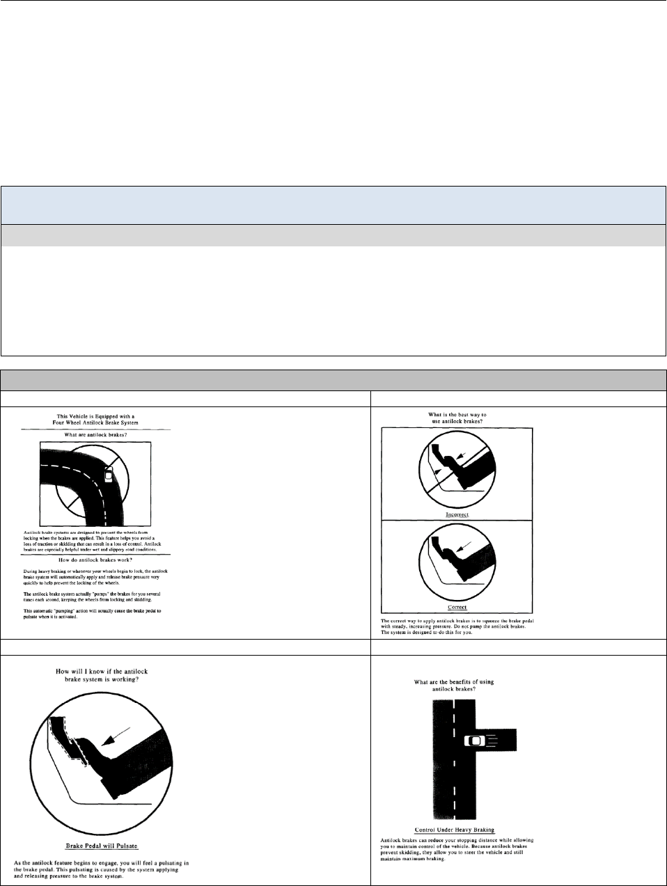
Example of a multipage informational pamphlet on antilock brakes (ABS) (from Mollenhauer et al. [3])
Page 1: Introduces the system and describes its function
Page 2: Shows how to use the system
• Describes the purpose of
the system, how the system
actually works and where
the system will be most
useful.
• Illustration shows a use
case, e.g., ABS leads to
better steering during heavy
braking, which may reduce
off-road crashes on curves.
• Indicates correct
and incorrect use
when active.
• Continues to
indicate how the
system works.
Page 3: Shows how drivers will know when the system is active
Page 4: Describes benefits to drivers
• Shows which cue indicates
the system has activated.
• Continues to indicate how
the system works.
• Lists benefits of
the system.
• Illustration shows
another use case,
e.g., ABS leads to
shorter braking
distance, which
may reduce
intersection entry
crashes.
Figures republished with permission of Pergamon, from Mollenhauer et al. (1997). Anti-lock brake systems: An assessment
of training on driver effectiveness. Accident Analysis and Prevention, 29; permission conveyed through Copyright Clearance
Center, Inc.

GENERAL DVI CONSIDERATIONS DVI DESIGN GUIDANCE
3-9
Discussion
The literature supports the idea of providing drivers with a detailed description of in-vehicle driver support systems.
However, assembling useful information in an effective manner is far from a simple practice. Potential benefits of effective
instructional material may include drivers reporting increased familiarity with the system, as well as reduced confusion
about what system messages mean. More importantly, with full descriptions of the meaning of interface states, drivers may
be more likely to use the system in a beneficial way when mental workload is high [2]. Adequate information provided by
proper labeling could also reduce the need for extensive training, and this topic is better referred to in previous design guidance
literature [5]. Instructional information regarding what to do when the system is activated may be useful to drivers [3].
According to standards and best practices, there are some system details that should be provided in the owner’s manual. As
an example, for a lane change decision assist system (LCDAS), the owner’s manual should include the following statement,
“this system may not provide adequate warning on curves tighter than x meters radius” where x is replaced by the tightest
curve radius for which the system is designed. The LCDAS manual should also indicate that if a trailer is put on the back of
the vehicle, the vehicle dimensions become different, which affects the function of the system [4]. It should be noted,
however, that while this type of information should be included in the owner’s manual, in the form it is presented above,
drivers may experience difficulty operationalizing the information.
For certain systems, a short informational pamphlet could be sufficient for providing adequate information to drivers. For
example, to illustrate the correct response when an ABS has been activated, a 4-page, informational pamphlet was effective
in transferring knowledge of the system [3]. The informational pamphlet conveyed verbal knowledge that included: (1) a
definition of ABS, (2) a general explanation of how ABS works, (3) an explanation of how drivers will know ABS is active,
and (4) an explanation of the benefits of using ABS correctly. Drivers who read the pamphlet stopped at shorter distances
when driving on ice and tended to use the correct braking technique. The information in the pamphlet was formatted to be
short and easy to read (e.g., it took less than 5 minutes for drivers to review). Another goal was to make the material visually
appealing to increase the likelihood of other drivers reading the material.
Design Issues
Despite the availability of useful and well put-together information, there is a chance that it will not be reviewed at all [6].
There is also a high chance that the information will not be understood by all those who review it. Yet, informational
material may be useful for those who do review it regularly when they switch vehicles. The transfer of knowledge gained
from experience with one vehicle to a second vehicle should not be assumed. For example, Lerner et al. [7] noted that, after
a few days of exposure to a particular auditory only FCW system, a new and different auditory alert was associated with a
delay in brake response. Although these findings have limited generalizability due to the laboratory-like conditions and very
high participant exposure to the FCW, they do illustrate some limitations to the transfer of experiential knowledge.
Another consideration is that drivers tend to over-generalize the purpose of available systems. They may think that the
assistance the system provides also applies to situations beyond the design purpose. For example, drivers who owned cars
with collision avoidance systems were presented with scenarios during which the systems in their cars would not be
functionally useful, yet many of the drivers were still erroneously confident that their systems would assist them in these
scenarios [6]. Driver training material (covered in Topic 3-10) is one method that can be used to help drivers generalize less
often to situations in which the functionaility of a system is comprised.
Cross References
Using Coverage Zones to Provide Lane Change Information, 4-8
Topic References
1. Allen, R. W. (1994, March). The driver’s role in collision avoidance systems. Workshop on Collision Avoidance Systems sponsored by the IVHS
America Safety & Human Factors Committee and the National Highway Traffic Safety Administration (pp. 33-57), Reston, VA.
2. Becic, E., Manser, M., Creaser, J., & Donath, M. (2012). Cooperative intersection collision avoidance system—stop sign assist: Experiments to
validate use of an in-vehicle interface design (Report No. CTS 12-09). Minneapolis: University of Minnesota Center for Transportation Studies.
3. Mollenhauer, M. A., Dingus, T. A., Carney, C., Hankey, J. M., & Jahns, S. (1997). Anti-lock brake systems: An assessment of training on driver
effectiveness. Accident Analysis and Prevention, 29, 97-108.
4. ISO 17387 (2008). Intelligent transport systems—Lane change decision aid systems (LCDAS)—Performance requirements and test procedures.
Geneva: International Organization for Standardization.
5. Campbell, J. L., Richard, C. M., Brown, J. L., & McCallum, M. (2007). Crash warning system interfaces: Human factors insights and lessons
learned, final report (Report No. DOT HS 810 697). Washington, DC: National Highway Traffic Safety Administration.
6. Jenness, J. W., Lerner, N. D., Mazor, S., Osberg, J. S., & Tefft, B. C. (2008). Use of advanced in-vehicle technology by young and older early
adopters. Selected results from five technology surveys (Report No. DOT HS 811 004). Washington, DC: National Highway Traffic Safety
Administration.
7. Lerner, N., Singer, J., Huey, R., Brown, T., Marshall, D., Chrysler, S., … & Chiang, D. P. (2015, November). Driver-vehicle interfaces for
advanced crash warning systems: Research on evaluation methods and warning signals. (Report No. DOT HS 812 208). Washington, DC:
National Highway Traffic Safety Administration.

DVI DESIGN GUIDANCE GENERAL DVI CONSIDERATIONS
3-10
Developing Driver Training Material
Introduction
Training is the process by which we acquire knowledge and skill on specific topics, systems, or applications. Many driver
training programs have been developed using rules of thumb that the designers of training curricula have honed over the
previous decades by incorporating methods that they “believe should be there,” but have been minimally influenced by
contemporary findings from the behavioral sciences [1]. This topic summarizes recent findings from the behavioral research
literature on several training methods that could be used to train drivers on the use of in-vehicle systems including, but not
limited to, safety applications. This DVI design topic may be most applicable to systems that are especially novel, complex,
or those within the heavy truck or bus environment, for which driver training programs are more frequently developed and
used.
Design Goal: Develop and evaluate training for systems or applications in a manner consistent with the goals
of the application.
Design Guidance
The best available research on this topic suggests that this design goal can be met when:
• Information on system functionality and system limits is provided in a driver training program [2].
• Variable priority training (VPT) is used, especially for complex multi-component systems. In VPT, trainees are presented a
complex task divided into subtasks between which they vary their attentional priority [3, 4]. (e.g., divide the task into Parts
A and B. Start with the trainee devoting 80 percent of their attention to Part A and 20 percent to Part B. Then, dedicate 20
percent to Part A and 80 percent to Part B. Finally, practice with 50 percent attention to both.).
• Error-training is used. It can reduce driver overconfidence and influence trainees to generate their own coping strategies for
when they encounter novel situations not covered in training [5].
• Training on the use and function of in-vehicle systems occurs after beginner drivers have obtained the basic and rudimentary
skills needed for safe-driving [2].
Simple 5-stage iterative training design model [6].
Content Prototype
Hand-off
Training
Test
Next
Cycle
• Literature Review
•
Focus group
•
One-to-ones
•
Task analysis
•
Testing
•
Training Manual
•
Simulator Scenarios
•
Focus group
•
Pilot test
• Train
-
the-
trainers
• Observe training
−Content: During the initial design phases of developing a training curriculum, a first step is to obtain training content
and information about general training requirements. This can be obtained through user interviews, focus groups,
and task analyses. Literature searching can be useful for preparing for user-testing and obtaining information about
driver tasks (e.g., previous task analyses [7]). The other phases of the iterative design process can also be used to
generate content for training.
−Prototype: Start by generating simple prototypes (e.g., paper-based drafts of a training manual) during this phase to
test training concepts and ensure the training content is appropriate. During subsequent iterations, generate more
complex prototypes (e.g., pilot-test class-room instruction or develop simulator-based scenarios) to test the
functional aspects of the training program—e.g., timetables for when certain topics are covered, methods of
presentation, etc.
−Test: The process of testing a prototype can be useful for obtaining additional design requirements as well as
uncovering implementation issues. Testing can include observations of trainers carrying out the training program.
−Next Cycle: This is a decision phase where the results of testing are used to decide if additional iterations are required.
−Hand-off Training: If testing indicates that iterations are no longer required, the training program is ready to be
handed off to trainers.

GENERAL DVI CONSIDERATIONS DVI DESIGN GUIDANCE
3-11
Discussion
While training material may not be necessary for all applications or user groups (e.g., it may be more of a priority for safety-
relevant applications with the heavy-vehicle environment), a training program should be systematic, deliberate, and
informed by research findings from the instructional design literature. A training program on driver safety systems can entail
different aspects of the system itself. Training sessions on support systems should focus on the functionality of the system,
including information on limitations and any potential for malfunction [2]. Such training programs could highlight any
significant limitation of the system for informing the driver of sudden hazards as well as limitations based on sensing
technologies used; for instance, drivers should be made aware of the possibility of certain LDW systems (e.g., with optical
sensors) providing warnings based on older lane markings that may not be entirely relevant.
Training programs should include information on how to read and interpret the DVI, available action options (e.g., brake,
steer, or both during a hazardous event), and instructions on acting out maneuvers (e.g., steer right or left, brake harder)
when the system is activated [8]. Instilling procedural knowledge by making suggestions to drivers on what to do in order to
maintain a safe field of travel is an effective strategy to help transform drivers’ knowledge about safety imminent situations
into the behavioral skills that are useful for crash avoidance [9, 10]. Proper training should also provide drivers with the
ability to transform and incorporate declarative knowledge (e.g., knowledge about the system) into more automatic-like
actions for using assistive systems during high workload situations. Such behavioral skills could become relatively immune
from deterioration in a broad range of contexts [9], especially if variable priority and error training methods are used. Novice
drivers, in particular, may also need general reminders on risk and situation awareness, personal attitudes, and risk
acceptance in order to drive responsibly and appropriately even when the car is equipped with in-vehicle safety applications
[11].
Different training strategies may be employed to ensure that drivers gain knowledge on and retain useful driving strategies. The
variable-priority training strategy is an effective training strategy for complex tasks. The method presents trainees with the
whole task, which is maintained during training, but different components are systematically emphasized or deemphasized to
allow more attention to be focused on specific parts while still preserving the necessary element of time-sharing of attention
across the whole task [4]. Drivers trained with this strategy tend to learn faster and reach higher levels of mastery compared
with training programs that emphasize all components equally [3, 4]. In addition, the error-training strategy where learners
acquire information about a task through exploration, testing self-generated hypotheses, and trial-and-error may be more
effective than the guided-error training where learners learn vicariously from examples of others’ errors [5]. In some cases,
different training settings may be necessary. Drivers between 70 and 89 years old benefit more after training is complete
when instructors provide feedback on actual driving in addition to classroom training [12]. As much as possible, training
should provide drivers with an ability to manage the traffic events and scenarios presented during training as well as novel
events not encountered during training.
Topic References
1. Brock, J. F., McFann, J., Inderbitzen, R. E., & Bergoffen, G. (2007). Effectiveness of commercial motor vehicle driver training curricula and
delivery methods (CTBSSP Synthesis MC-13). Washington, DC: National Academy Press.
2. Panou, M. C., Bekiaris, E. D., & Touliou, A. A. (2010). ADAS module in driving simulation for training young drivers. Proceedings of the
13th International IEEE Annual Conference on Intelligent Transportation Systems, 1582-1587.
3. Boot, W. R., Basak, C., Erickson, K. I., Neider, M., Simons, D. J., Fabiani, M., ... & Kramer, A. F. (2010). Transfer of skill engendered by
complex task training under conditions of variable priority. Acta Psychologia, 135, 349-357.
4. Wickens, C. D., Hutchins, S., Carolan, T., & Cumming, J. (2013). Effectiveness of part-task training and increasing-difficulty training
strategies: A meta-analysis approach. Human Factors, 55, 461-470.
5. Ivancic, K., & Hesketh, B. (2000). Learning from errors in a driving simulation: Effects on driving skill and self-confidence. Ergonomics,
43(12), 1966-1984.
6. Graving, J. S., Easterlund, P. A., & Manser, M. M. (2011). Developing a bus driver training program for a driver assistive system. Proceedings
of the Human Factors and Ergonomics Society 55th Annual Meeting, 1543-1547.
7. McKnight, J., & Adams, B. (1970). Driver education and task analysis, Volume 1: Task descriptions (Report No. DOT HS 800 367).
Washington DC: National Highway Traffic Safety Administration.
8. Tijerina, L. (1995). Key human factors research needs in IVHS crash avoidance. Transportation Research Record: Journal of the
Transportation Research Board, 1485, 1-9.
9. Rasmussen, J. (1983). Skills, rules, and knowledge: Signals, signs, and symbols, and other distinctions in human performance models. IEEE
Transactions on Systems, Man, and Cybernetics, SMC-13(3), 257-266. doi: 10.1109/TSMC.1983.6313160
10. Gibson, J. J., & Crooks, L. (1938). A theoretical field-analysis of automobile driving. American Journal of Psychology, 51, 435-471.
11. Barker, P., & Woodcock, A. (2011). Driver skills, education and in-vehicle technology. International Journal of Vehicle Design, 55(2-4), 189-
207.
12. Porter, M. M. (2013). Older driver training using video and global positioning system technology—a randomized controlled trial. Journals of
Gerontology Series A: Biomedical Sciences and Medical Sciences, 68(5), 574-580. doi:10.1093/Gerona/gls160. Epub 2012 Aug 9

DVI DESIGN GUIDANCE GENERAL DVI CONSIDERATIONS
3-12

GUIDANCE FOR SAFETY MESSAGES DVI DESIGN GUIDANCE
4-1
Chapter 4. Design Guidance for Safety Messages
This chapter provides a collection of general human factors information relevant to interface
design. This information directly impact driver use of, and benefit from, safety systems. The
chapter consists of system implementation topics. For some topics, real-world examples of
deployment methods are provided.
Topics included in this chapter:
• False and Nuisance Warnings
• Multimodal Warning Messages
• Warning Stages
• Providing Forward Collision Warnings That Accommodate Driver Brake Reaction Time
• Using Coverage Zones to Provide Lane Change Information

DVI DESIGN GUIDANCE GUIDANCE FOR SAFETY MESSAGES
4-2
False and Nuisance Warnings
Introduction
False alarms are defined as alarms that indicate a threat when no threat exists. They can cause driver distraction, incorrect
decisions and/or responses, and distrust in the crash warning system (CWS). Furthermore, they may increase reaction time
to true warnings. Nuisance alarms are defined as alarms that correctly indicate a potential threat, but that the driver does not
believe are warranted or neededperhaps because the driver was already aware of the threat or believes that the threat will be
resolved without driver intervention. However, drivers may not necessarily make distinctions between false and nuisance
alarms. This topic provides information for minimizing the occurrence of false and nuisance alarms, and reducing the
negative effects of these warnings on driver performance and acceptance of the CWS.
Design Goal: Minimize false and nuisance warnings and their effects on driver performance and acceptance.
Design Guidance
The best available research on this topic suggests that this design goal can be met when the following false/nuisance alarm
rates and strategies for collision avoidance systems, and emerging technologies such as connected vehicle systems, are
considered:
• Longitudinal warning systems (forward crash warning, curve speed warning, etc.)
−Limit imminent crash warning nuisance alarms to 0.5 per 100 miles [1].
−Mitigate driver annoyance with nuisance warnings by avoiding the use of auditory and haptic for cautionary crash
warnings.
• Lateral warning systems (lane change warning, blind spot warning, etc.)
−Drivers are not likely to consider even relatively high rates of nuisance alarms to be annoying, as long as the
warnings are unobtrusive and presented via the visual modality only [2, 3].
• General Strategies
−From Lerner, Kotwal, Lyons, and Gardner-Bonneau [4] and Horowitz et al. [5], some strategies for minimizing the
frequency and impact of false/nuisance warnings include:
1. Deactivate a warning device automatically when it is not needed during a particular driving situation
(i.e., require the shift lever to be in reverse gear to place a backup warning device in the active mode).
2. Allow the driver to reduce detection sensitivity to a restricted limit that minimizes false/nuisance warnings
without significantly affecting the target detection capability of the device.
3. Present a warning only after a target or critical situation has been detected as continuously present for some
specified minimum time.
4. Mitigate annoyance by allowing the driver to reduce warning intensity or volume.
5. Change modality as the severity of the situation increases (e.g., warn first visually, then add auditory
component as severity increases).
−Use redundancy across systems (e.g., steering and machine vision inputs to a lane departure warning) to increase the
information available to the system and reduce the potential for false alarms.
−Use sensors to detect whether or not a driver has already begun to initiate a crash avoidance maneuver. Sensors that
detect adjustments to steering, the accelerator, brakes, or other control aspects can be used to reasonably predict a
driver’s response [see Wilson et al., 6].
Note: While this information reflects the best available evidence for general use, caution is advised when this guidance is
applied to the design of heavy-vehicles/buses applications due to differences in driving exposure and operational
conditions.

GUIDANCE FOR SAFETY MESSAGES DVI DESIGN GUIDANCE
4-3
Discussion
False and nuisance alarms can affect both driver acceptance and performance. In Sayer et al. [2], drivers received high
rates of nuisance alarms (both visual and auditory) but generally did not consider them to be annoying, in part because
they felt that the safety advantages of the system outweighed its shortcomings. Talmadge et al. [3] examined false
alarm rates in LCW systems and found drivers did not consider the relatively high rate of false alarms (42 per hour) as
annoying. In both studies, the lateral alarms were unobtrusive and visual, and most alarms occurred when drivers
would not have noticed them or when they were in a situation where a lane change was unlikely (e.g., in a turn). In
Abe and Richardson [7], drivers who experienced late alarms were reluctant to respond to a false alarm; those who
experienced early alarms had a delayed response to critical situations when no alarm was presented.
A nuisance alarm rate of less than 0.5 per hundred miles for an FCW ICW system is consistent with the value
recommended by Kiefer et al. [1]; this value would result in the average driver receiving a single nuisance alarm per
week. Similarly, although more than half of the drivers in Sayer et al. [2] found the nuisance alarm rate of 0.83 per
hundred miles of driving to be acceptable, some drivers considered this too high and ignored warnings. With greater
daily miles driven, commercial vehicles may require a lower level of false alarms to support driver acceptance.
Design Issues
Nuisance alarms could be reduced by integrating a crash warning system into a larger sensor suite that can assess whether or not
a driver has initiated a crash avoidance maneuver [6]. While empirical data regarding their false alarm rate is lacking, emerging
technologies such as CV have the potential to reduce false alarms compared with traditional CWSs as there may be more
information available to use in determining when to present alerts. Robust CV systems should include mitigations for sources of
error such as erroneous or missing GPS signals, communication errors, or other system malfunctions that may potentially result
in false or missing alarms. However, the potential benefits of CV technology may still require supplementary sensing for
objects that are not part of the CV infrastructure, such as non-CVs, pedestrians, and other objects in the roadway.
Advanced warning system technologies may present issues of perceived reliability, especially if they are able to
initiate warnings for hazards that are not immediately visible to the driver (e.g., rear cross-traffic alert or predictive
FCW systems). The results from a small-sample simulator study suggest that drivers may have greater trust in systems
that provide follow-up feedback when a situation becomes non-critical after the system activates a warning [8]; these
results may have limited applicability due to the high degree of participant training and exposure to near-crash events
typical of simulator studies. Focus group data [9] show drivers may be more annoyed when given false information
about events that require strategic and proactive action (e.g., finding parking, route changes, etc.) as compared to false
information that does not have a clear negative impact on the driver (e.g., school zone ahead, severe weather ahead,
etc.). Focus group participants [9] indicated high acceptance for imperfect collision warning systems, implying drivers
find value in collision warnings but may not fully appreciate diminished performance associated with false alarms.
Horowitz and Dingus [5] provided four concepts for minimizing effects of false alarms: (1) present graded warnings,
(2) change modality as severity escalates (e.g., visual CCW then visual-plus-auditory ICW as severity increases), (3)
make some settings driver-adjustable, and (4) present headway displays as initial status devices that expand to provide
warnings as needed. Forms of these strategies may be appropriate in the design of safety application DVIs.
Cross References
Warning Stages, 4-6
Topic References
1. Kiefer, R., LeBlanc, D., Palmer, M., Salinger, J., Deering, R., & Shulman, M. (1999). Development and validation of functional definitions and
evaluation procedures for collision warning/avoidance systems (Report No. DOT HT 808 964). Washington, DC: National Highway Traffic Safety
Administration.
2. Sayer, J. R., Bogard, S. E., Buonarosa, M. L., LeBlanc, D. J., Funkhouser, D. S., Bao, S., ... & Winkler, C. B. (2011). Integrated vehicle-based
safety systems light-vehicle field operational test key findings report. (Report No. DOT HS 811 416). Washington, DC: National Highway Traffic
Safety Administration.
3. Talmadge, S., Chu, R., Eberhard, C., Jordan, K., & Moffa, P. (2000). Development of performance specifications for collision avoidance systems for
lane change crashes (Report No. DOT HS 809 414). Washington, DC: National Highway Traffic Safety Administration.
4. Lerner, N. D., Kotwal, B. M., Lyons, R. D., & Gardner-Bonneau, D. J. (1996, January). Preliminary human factors guidelines for crash avoidance
warning devices (Report No. DOT HS 808 342). Washington, DC: National Highway Traffic Safety Administration.
5. Horowitz, A. D., & Dingus, T. A. (1992). Warning signal design: A key human factors issue in an in-vehicle front-to-rear-end collision warning
system. Proceedings of the Human Factors Society 36th Annual Meeting, 1011-1013.
6. Wilson, T., Miller, S., Burns, M., Chase, C., Taylor, D., Butler, W., ... & Dingus, T. A. (1998). Light vehicle forward-looking, rear-end collision
warning system performance guidelines (Report No. DOT HS 808 948). Washington, DC: National Highway Traffic Safety Administration.
7. Abe, G., & Richardson, J. (2006). The influcnce of alarm timing on driver response to collision warning systems following system failure. Behavior
& Information Technology, 25(5), 443-452.
8. Westat, Inc. (2014). Connected vehicle DVI design research and distraction assessment. Draft final report: Review package #3 (Unpublished draft
report prepared forNHTSA under contract DTNH22-11-D-00237).
9. Westat, Inc. (2014). Connected vehicle DVI design research and distraction assessment. Draft final report: Review package #6 (Unpublished draft
report prepared forNHTSA under contract DTNH22-11-D-00237).

DVI DESIGN GUIDANCE GUIDANCE FOR SAFETY MESSAGES
4-4
Multimodal Warning Messages
Introduction
A multimodal warning message consists of more than one type of signal from the visual, haptic, and auditory
modalities. The benefits of having multimodal alerts and warnings (versus unimodal) are substantial across a number
of different driving scenarios, types of collisions, and driver populations. These benefits include detectability
regardless of where drivers are looking (for auditory messages) and having a “back-up” communication channel if
there is high ambient noise/vibration (for visual messages). This topic provides information on how to create
multimodal messages.
Design Goal: Present simultaneous auditory, haptic, or visual signals to generate a warning message that is
quickly and reliably detected and understood by the driver.
Design Guidance
The best available research on this topic suggests that this design goal can be met when:
• Multiple, simultaneously-activated signals are used to provide redundancy, maximizing the likelihood a driver will receive an
alert [1, 2].
• Multiple signals are used to create a sequential change in modality for different stages of a graded system—e.g., less
imminent stages of a warning can be represented using a less invasive signal like a static visual icon, and auditory can be used
for more imminent alerts [3].
• Non-attention-getting visual components of a multimodal message persist beyond the duration of other warning signals to
provide post-alert information regarding the nature of the warning [3].
Example considerations for specific functions of different display types used for a multimodal display.
Modality
Description
Visual
Displays
Head-Up Display (HUD): Used in conjunction with auditory or haptic alerts to encourage drivers to
attend to the forward roadway in safety critical situations; HUD images should not block the drivers view
of forward hazards [3].
High Head-Down Display (HHDD): Used to improve noticeability of the visual aspects of the warning
or alert for drivers who are unable to hear or feel the signals from the other modalities that are used [3].
Low Head-Down Display (LHDD): Used to present visual messages but the presentation period should
begin after the warning criterion is no longer exceeded; must be paired with auditory or haptic signals [3].
Instrument Panel (IP) Display: Used to present visual messages. However, the use of this space as part
of a multimodal display for safety critical information is not recommended [4]
Auditory
Displays
Speech Messages: Speech can also be used to more clearly indicate the nature of the hazard as part of a
multimodal display. Speech may lead to better driver compliance with appropriate driving behavior [5]
when the imminence of the event is not too severe.
Simple Tones (Conventional Auditory): Commonly paired with haptic and visual. Spatial messages
using simple tones are enhanced greatly when coupled with spatial haptic messages (e.g., Fitch et al., [6]).
Haptic
Displays
Vibrotactile Seat: Commonly paired with auditory, e.g., the addition of audio or visual displays may
facilitate driver comprehension of more complex vibrotactile seat displays.
Steering Wheel Torques: Commonly paired with a visual and/or auditory display.
Vibrotactile Steering wheel: Commonly paired with a visual and/or auditory display. Vibrotactile
displays are generally rated low in intrusiveness, and are often paired with auditory displays.
Other Haptic/Tactile Displays: May be implemented as part of a multimodal warning system. However,
limited research is available regarding the use of seat belt pre-tensioning or brake pulses as a component
of a multimodal display.

GUIDANCE FOR SAFETY MESSAGES DVI DESIGN GUIDANCE
4-5
Discussion
Many vehicle displays are bimodal, presenting both visual and auditory signals. A bimodal presentation scheme can be
employed for in-vehicle tell-tale messages using a tone to alert the driver to a system issue, which is coupled with a visual
component (e.g., a tell-tale icon) to convey the nature of the system problem [3]. In addition, there are several usability
advantages attached to multimodal displays. Many drivers find multimodal warnings more useful than unimodal warnings [7],
and the use of multimodal displays may also help drivers with unisensory deficits (e.g., age-related hearing problems [2]).
Auditory or tactile signals may be used to avoid overloading driver’s visual system [8]. Auditory and haptic signals are
detectable regardless of where drivers look. Visual warnings can serve as “back-up” communication channels if there is high
ambient noise/vibration or if a driver is hearing impaired [3]. Visual warnings serve well as a method for portraying the
nature of an alert [3].
Many studies have demonstrated the benefits of multisensory signals when each signal conveys the same information (e.g.,
[7, 8, 9]). A proof-of-concept evaluation of a multimodal curve speed warning system found compliance was greatest with
multimodal displays, with the auditory and visual displays providing clear information about what the driver should do [5].
Likewise, collision avoidance performance for both forward and side object collisions may be best when a bimodal
auditory/visual warning system is used, which extends across driving scenarios, types of collisions, and driver populations
[2, 10].
Design Issues
Forming a full correspondence between multiple unnatural multisensory stimuli is unlikely to occur without significant
training [11]. Therefore, warning signals need to be intuitive and easily learned [7, 8], yet the redundant temporal cues may
still be useful when multimodal signals co-occur.
There may be some benefit to a cross-modal paradigm for enhancing responses. For instance, a study in a driving simulator
reported by Lerner et al. [13] found that response time is enhanced when there is a verbal or tone-based auditory early-alert
that precedes a haptic warning. Despite the observed benefits of multimodal alerts, however, sequential alerts could have
some drawbacks. For example, if a driver hears an auditory alert, is responding to that alert, and then sees a redundant visual
alert, that redundant visual alert still needs to be processed and thus can in theory increase the time it takes to respond. Lee et
al. [9] found that brake reaction time increased with a multimodal display. They suggest that performance may degrade
when a multimodal warning is perceived as multiple cues, but performance gains can be achieved through matching the
characteristics of multi-modal signals in a way that the warning is perceived as a single cue.
Cross References
Developing Driver Training Material, 3-10; Warning Stages, 4-6
Topic References
1. Hecht, D., & Reiner, M. (2009). Sensory dominance in combinations of audio, visual and haptic stimuli. Experimental Brain Research, 193,
307-314.
2. Laurienti, P. J., Burdette, J. H., Maldjian, J. A., & Wallace, M. T. (2006). Enhanced multisensory integration in older adults. Neurobiology of
Aging, 27, 1155-1163.
3. International Organization for Standardization. (2005). Road vehicles—Ergonomic aspects of in-vehicle presentation for transport information
and control systems—Warning systems (ISO/TR 16352). Geneva: Author.
4. Perez, M. A., Kiefer, R. J., Haskins, A., & Hankey, J. M. (2009). Evaluation of forward collision warning system visual alert candidates and SAE J2400.
SAE International Journal of Passenger Cars—Mechanical Systems¸ 2(1), 750-764.
5. Neurauter, M. L. (2005). Multimodal warnings: Curve-warning Design. Proceedings of the Human Factors and Ergonomics Society 49th
Annual Meeting, 49(22), 1945-1949.
6. Fitch, G. M., Kiefer, R. J., Hankey, J. M., & Kleiner, B. M. (2007). Toward developing an approach for alerting drivers to the direction of a
crash threat. Human Factors, 49(4), 710-720.
7. Maltz, M., & Shinar, D. (2004). Imperfect in-vehicle collision avoidance warning systems can aid drivers. Human Factors, 46, 357-366.
8. Spence, C., & Ho, C. (2008). Multisensory warning signals for event perception and safe driving. Theoretical Issues in Ergonomics Science, 9,
523-554.
9. Lee, J. D., McGehee, D. V., Brown, T. L., & Marshall, D. (2006). Effects of adaptive cruise control and alert modality on driver performance.
Transportation Research Record: Journal of the Transportation Research Board, 1980, 49-56.
10. Kramer, A. F., Cassavaugh, N., Horrey, W. J., Becic, E., & Mayhugh, J. L. (2007). Influence of age and proximity warning devices on collision
avoidance in simulated driving. Human Factors, 49, 935-949.
11. Spence, C., Ngo, M. K., Lee, J.-H., & Tan, H. (2010). Solving the correspondence problem in haptic/multisensory interface design. In M. H.
Zadeh (Ed.). Advances in Haptics (pp. 47-74). Available from: www.intechopen.com/books/advances-in-haptics/solving-thecorrespondence-
problem-in-haptic-multisensory-interface-design
13. Lerner, N., Singer, J., Huey, R., Brown, T., Marshall, D., Chrysler, S., … & Chiang, D. P. (2015, November). Driver-vehicle interfaces for advanced
crash warning systems: Research on evaluation methods and warning signals. (Report No. DOT HS 812 208). Washington, DC: National Highway
Traffic Safety Administration.

DVI DESIGN GUIDANCE GUIDANCE FOR SAFETY MESSAGES
4-6
Warning Stages
Introduction
This topic presents information regarding the use of multi-stage graded warnings versus one-stage warnings.
Generally, a one-stage warning system provides only an ICW (requires immediate corrective action), while a two-
stage system provides a CCW (requires immediate attention and possible corrective action) followed by a separate
ICW. A graded warning may include two or more stages of cautionary information that increase in urgency
proportionally with the criticality of the hazard situation prior to the presentation of an ICW.
Design Goal: Determine the number of warning stages needed to promote drivers’ comprehension of, and
response to, the hazard.
Design Guidance
The best available research suggests these heuristics for selecting one- versus multi-stage warnings:
• Consider using a one-stage warning:
−For applications in which earlier-stage warnings of a two-stage system may be perceived as nuisance
warnings.
−If the rate of false alarms associated with a two-stage system significantly reduces driver trust in the system
or increases driver frustration with the system.
−In potential crash situations that evolve too rapidly for a cautionary warning to be effective (e.g., an FCW
cautionary warning that rapidly or ambiguously transitions to an imminent stage).
−With ICWs, as a reliable warning presented earlier may be more beneficial for safety than a later warning.
• Consider using a two-stage warning:
−When a key goal of the system is to promote a long-term modification of driving behavior.
−In situations where hard braking could have an undesirable effect (e.g., lower customer satisfaction in buses
and load shifts for heavy vehicles). Hard-braking may be more likely with one-stage systems that only
activate for imminent situations.
−For alerts related to vehicles in an adjacent lane (i.e., if the visual display is located in the far periphery—
such as in the side mirror, on the A-pillar, etc.—when the driver is looking forward). Examples of such
applications may include LCW and BSW systems).
• Consider using a multi-stage graded warning system when the primary goal of the system is to provide continuous
information (e.g., headway information in an FCW, continuous proximity to vehicle in BSW, LCW, or reverse collision
warning (RCW), etc.).
Advantages and disadvantages of using one-stage versus two-stage warnings.
ICW Only (One-stage) CCWs + ICW (Two-stage or Graded)
Advantages
• May result in fewer nuisance
warnings.
• May be simpler for drivers to
comprehend.
• May avoid confusion arising
from rapidly changing warning
states.
• May minimize requirements for hard braking (has value for
buses and heavy vehicles).
• May assist drivers in developing a coherent mental model and
better awareness of the CWS device.
• May reduce startle effects from ICWs alone.
• May aid drivers in maintaining safe headway and in anticipating
potential crashes.
Disadvantages
• May provide less time for the
driver to recognize and respond
to an emerging crash situation.
• May confuse drivers if the alert transitions from CCW to ICW
too quickly.
• May increase likelihood of real or perceived false alarms.
• May reduce driver trust and use of the system due to false
alarms.

GUIDANCE FOR SAFETY MESSAGES DVI DESIGN GUIDANCE
4-7
Discussion
Single-stage warnings have some reported benefits. Kiefer et al. [1] found that a single-stage FCW was more effective under
distracted-driver conditions than two-stage warnings with a visual-only CCW [1]. Furthermore, Kiefer et al. [2] note that a
one-stage warning is the preferable warning configuration for the following reasons: (1) better driver acceptance because of
fewer nuisance alarms, (2) better compatibility with more effective warning algorithms, (3) provides a simpler mental model
for drivers to comprehend, and (4) avoids the potential ineffectiveness of—and driver confusion arising from—cautionary
warning alerts because the CCW stage is very brief in practice. With the increase in applications potentially available
through CV technology, the use of single-stage warnings can minimize drivers’ exposure to too many warning signals in
systems with many integrated applications.
Other research shows benefits from two-stage warnings in similar driving situations [3-7], and most sources recommend
two-stage warnings. Graded warnings may aid drivers by priming their responses to the ICW [3]. Two-stage warnings may
be more appropriate in situations other than FCW, such as LCW and LDW, and with heavy vehicles because of different
situational factors that increase the utility of cautionary warning information [8, 9]. Lerner, Kotwal, Lyons, & Gardner-
Bonneau [4] notes that: (1) CCWs assist drivers in developing a mental model of the system, (2) they may reduce ICW
startle effects, and (3) because true ICWs are relatively rare, the CCWs help keep drivers aware of the FCW system. Another
option examined in the literature is a five-stage looming display for FCW that indicates: (1) no vehicle detected, (2) vehicle
detected, (3) caution, (4) approaching imminent, and (5) imminent [5].
Design Issues
Selection of one- versus two-stage warning should include careful consideration of the display features and modality
selected for each stage. For example, driving simulator research by Lerner et al. [8] found that responses to tone-based alerts
were faster when an early verbal-auditory alert was provided, but slower when the early alert was tone-based. They also
found that responses to a haptic warning were enhanced by early-alerts that were verbal or tone-based. Research in single-
stage warnings has indicated that earlier warnings are beneficial and that late warnings may not be as effective [9].
Additionally, other research suggests that if graded warnings are used, the transition from CCW to ICW must be clear and
unambiguous [4].
The timing of warning stages is important. If the CCW is presented too late, drivers may not have time to understand the
rapidly evolving hazard situation and become confused by the rapid change from CCW to ICW [2]; however, if the CCW is
presented too early, drivers may perceive the alert to be a false alarm and distrust the system or possibly delay responses to
the subsequent ICW.
Two-stage warnings for LDW or BSW systems may be particularly useful when the visual displays are located in the side
mirrors or A-pillar as they are generally available only when the driver is looking for information from them (i.e., checking
the mirrors before a lane change). In these situations, the CCW visual signals will most likely not be considered a nuisance,
and they could provide sufficient advance information of a potential threat that an ICW is not necessary.
Topic References
1. Kiefer R. J., Cassar, M. T., Flannagan, C. A., Jerome, C. J., & Palmer, M. D. (2005). Surprise braking trials, time-to-collision judgments, and
“first look” maneuvers under realistic rear-end crash scenarios (Forward Collision Warning Requirements Project, Tasks 2 and 3a Final
Report, Report No. DOT HS 809 902). Washington, DC: National Highway Traffic Safety Administration, Office of Advanced Safety
Research.
2. Kiefer, R., LeBlanc, D., Palmer, M., Salinger, J., Deering, R., & Shulman, M. (1999). Development and validation of functional definitions and
evaluation procedures for collision warning/avoidance systems (Report No. DOT HT 808 964). Washington, DC: National Highway Traffic
Safety Administration.
3. Lee, J. D., Hoffman, J. D., & Hayes, E. (2004). Collision warning design to mitigate driver distraction. Proceedings of the SIGCHI Conference
on Human Factors in Computing Sciences (pp. 65-72). Available at
http://citeseerx.ist.psu.edu/viewdoc/download?doi=10.1.1.77.2168&rep=rep1&type=pdf
4. Lerner, N. D., Kotwal, B. M., Lyons, R. D., & Gardner-Bonneau, D. J. (1996, January). Preliminary human factors guidelines for crash
avoidance warning devices (Report No. DOT HS 808 342). Washington, DC: National Highway Traffic Safety Administration.
5. General Motors Corporation & Delphi-Delco Electronic Systems. (2002). Automotive collision avoidance system field operation test, warning
cue implementation summary report (Report No. DOT HS 809 462). Washington, DC: National Highway Traffic Safety Administration.
6. Pierowicz, J., Jocoy, E., Lloyd, M., Bittner, A., & Pirson, B. (2000). Intersection collision avoidance using ITS countermeasures (Report No.
DOT HS 809 171). Washington, DC: National Highway Traffic Safety Administration.
7. Mendoza, P. A., Angelelli, A., & Lindgren, A. (2011). Ecological interface design inspired human machine interface for advanced driver
assistance systems. IET Intelligent Transport Systems, 5(1), 53-59.
8. Lerner, N., Singer, J., Huey, R., Brown, T., Marshall, D., Chrysler, S., … & Chiang, D. P. (2015, November). Driver-vehicle interfaces for
advanced crash warning systems: Research on evaluation methods and warning signals. (Report No. DOT HS 812 208). Washington, DC:
National Highway Traffic Safety Administration.
9. Westat, Inc. (2014). Connected vehicle DVI design research and distraction assessment. Draft final report: Review package #3 (Unpublished
draft report prepared forNHTSA under contract DTNH22-11-D-00237).

DVI DESIGN GUIDANCE GUIDANCE FOR SAFETY MESSAGES
4-8
Providing Forward Collision Warnings that Accommodate Driver Brake Reaction Time
Introduction
This topic describes the different elements of a brake reaction time relevant to FCWs and provides general design
information and key research findings relevant to the timing of warnings. Driver brake reaction time is the key human
factors element to the Basic Equation of Collision Warning in ISO 15623 [1].
Design Goal: Provide a forward collision warning that accommodates drivers’ brake reaction time.
Design Guidance
The best available research on this topic suggests that this design goal can be met when:
• Estimates of stopping time to forward hazards includes perception-response time, the time it takes a driver to remove their
foot from the accelerator pedal and apply it to the brake pedal, and the amount of time it takes to fully depress the brake [2].
• FCWs are issued early enough so that there is time to allow drivers to determine how to respond, depress the brake pedal and
slow the momentum of the vehicle [3].
• The timing of the alert is no later than the driver’s unassisted accelerator release; this may enhance driver trust for FCWs [4].
Warning algorithms that use lower required driver deceleration levels (e.g., a
1
= 0.35 g) are associated with greater trust
ratings compared to those that use greater values (e.g., a
1
= 0.75 g) [4].
The basic equation of a forward collision warning system [1].
This excerpt is adapted from ISO 15623:2013, Figure A.1 on page 18,
with the permission of ANSI on behalf of ISO. (c) ISO 2014 - All rights reserved [1]
Stopping time model: Driver and vehicle aspects.
Brake Reaction Time
Mental Processing Time
Foot
Movement
Time
Vehicle
Response
Time
Hazard Present (e.g. lead vehicle brakes)
Sensation Perception
Response
Selection &
Preparation

GUIDANCE FOR SAFETY MESSAGES DVI DESIGN GUIDANCE
4-9
Discussion
ISO 15623 [1] provides a basic equation for the timing of an FCW, including a parameter called free running distance (top
figure on page 4-8) that is the product of driver brake reaction time (grayed area in bottom figure on page 4-8) and vehicle
speed (representing the distance traveled between event onset and brake application).” In addition to driver brake reaction
time, ISO 15623 indicates that there should be a minimum of 0.8 seconds for the driver to respond to the alert, with the
implemented value for driver brake reaction time as a design parameter to be determined by the manufacturer. While ISO
15623 provides some limited information on driver brake reaction time, additional research provides a convincing argument
against the use of a canonical value for driver brake reaction time to forward events [2, 5, 6, 7]. However, the research is less
conclusive about values associated with contributing factors.
Stopping time is comprised of several components: the mental processing time (how long it takes the driver to sense,
perceive, and decide upon a reaction), the movement time (how long it takes the driver to physically activate the brake
pedal), and the vehicle response time (how long it takes the vehicle’s braking system to engage and bring the vehicle to a
stop) [6]. The first two components, mental processing time and movement time, may be referred to as brake reaction time
and are subject to individual differences. The last component, vehicle response time, is a function of the vehicle engineering,
however the driver’s ability to effectively actuate the brakes and slow or stop the vehicle in panic situations is highly
variable and typically below the vehicle braking system’s optimal abilities [8].
With respect to the DVI for a CWS, the first two components (mental processing time and movement time) are critical in
terms of a CWS’s DVI design. Both the potential range of driver characteristics, as well as the current state of the driver,
may be considered in designing an optimal warning interface. Driver reaction time is highly variable. Laboratory and test
track studies have found effects of expectancy, driving experience, age, cognitive and visual load [2, 9], arousal and fatigue,
and urgency [5] on brake reaction time. Naturalistic driving data suggests the presence of significant effects of eyes off road
time, age, weather, traffic density, and lighting conditions upon brake reaction time [7]. Taken as a whole, the research
suggests that expectancy, experience, arousal, and situational urgency generally reduce brake reaction time, while increasing
age, cognitive and visual loading, lower levels of arousal or fatigue, increased eyes off road time, poorer weather conditions,
heavy traffic density, and poor lighting conditions are associated with increased brake reaction time. Values from research
[2] indicate that a primed (expectant of the cue) driver under optimal conditions may have a brake reaction time of under 1 s,
while analysis of naturalistic data [7] suggest that brake reaction time could range from 1.5 s to 2.5 s (and occasionally
greater depending on driver state, such as distraction). However, as mentioned above, the lack of consensus within the
research precludes the use of a canonical value for driver brake reaction time.
Design Issues
Simulator research [10] shows that longer or shorter warning timing may affect driving differently. Over 3 days of
testing early and later warnings warnings (i.e., 3.2 s and 2.2 s time-to-collision (TTC)), only early warnings lead to a
headway buffer that was substantially different from the warning timing (i.e., on the 3rd day of testing, median
headway was 4.5 s when the warning was early, and 2.5 s when it was late). Early warnings occur when there is more
distance between vehicles and are thus more likely to activate compared to later warnings. In this study [10], drivers
with the early alert that increased their headway also substantially reduced the frequency of alerts over time.
DSRC messages can have latencies with durations up to 1000 ms that may lead to communicating invalid positional
information [11]. Whatever the specific latency of a system, this latency will need to be incorporated into the
algorithms used to issue a warning.
Cross References
False and Nuisance Warnings, 4-2; Warning Stages, 4-6
Topic References
1. ISO 15623 (2013). Transport information and control systems - Forward vehicle collision warning systems - Performance requirements and
test procedures. Geneva: International Organization for Standardization.
2. Green, M. (2000). How long does it take to stop? Methodological analysis of driver perception-brake time. Transportation Human Factors,
2(3), 195-216.
3. Lee, J. D., McGehee, D. V., Brown, T. L., & Reyes, M. L. (2002). Collision warning timing, driver distraction and driver response to imminent
rear-end collisions in a high-fidelity simulator. Human Factors, 44(2), 314-334.
4. Abe, G., & Richardson, J. (2005). The influence of alarm timing on braking response and driver trust in low speed driving. Safety Science, 43,
639-654.
5. Summala, H. (2000). Driver Brake Reaction times and driver behavior analyses. Transportation Human Factors, 2(3), 217-226.
6. Green, M. (2009). Perception-reaction time: Is Olson (and Sivak) all you need to know? Collision, 4(2), 88-93.
7. Dozza, M. (2013). What factors influence drivers’ response time for evasive maneuvers in real traffic. Accident Analysis and Prevention, 58,
299-308.
8. Hara, M., Ohta, M., Yamamoto, A., & Yoshida, H. (1998). Development of the brake assist system (Paper No. 98-S2-P-17). Paper presented at
the 16th International Technical Conference on the Enhanced Safety of Vehicles. Windsor, Canada.
9. Kiefer, R., LeBlanc, D., Palmer, M., Salinger, J., Deering, R., & Shulman, M. (1999). Development and validation of functional definitions and
evaluation (Report No. DOT HT 808 964). Washington, DC: National Highway Traffic Safety Administration.
10. Westat, Inc. (2014). Connected vehicle DVI design research and distraction assessment. Draft final report: Review package #3 (Unpublished
draft report prepared forNHTSA under contract DTNH22-11-D-00237).
11. Tang, A., & Yip, A. (2010). Collision avoidance timing analysis of DSRC-based vehicles. Accident Analysis and Prevention, 42, 182-195.

DVI DESIGN GUIDANCE GUIDANCE FOR SAFETY MESSAGES
4-10
Using Coverage Zones to Provide Lane Change Information
Introduction
Standards for lane change assistance systems (e.g., ISO [1], SAE [2]) contain specific dimensions for adjacent-vehicle
detection coverage zones that surround the driver’s vehicle. Some dimensions are advised to be relative to specific
vehicle and driver variables (e.g., coverage zones typically extend rearward from the position to the 95th percentile
eyellipse, to 3 m behind the vehicle). This topic contains information on how to consider driver and vehicle variables
for determining when to provide information to support lane change decisions.
Design Goal: Activate a lane change collision avoidance message when other vehicles enter the driver’s blind
zone area.
Design Guidance
The best available research on this topic suggests that this design goal can be met when:
• Systems deliver a blind spot message when vehicles enter the coverage zones (blind zone area below) that extend from the
side and rear of the vehicle.
• Systems determine the driver’s intention to change lanes. This can be accomplished by assessing turn signal status, steering
input, or lane position [1]; patterns of surrounding traffic (e.g., evaluating gaps between adjacent vehicles and forward
headway) relative to the driver’s speed [3] or driver gaze [4].
• Warnings may be suppressed when the driver is overtaking a lead vehicle [1]. Drivers may be aware of vehicles they are
passing when they are intentionally overtaking a lead vehicle. This is optional in the ISO standard [1].
ISO/SAE lane change decision assist system hazard detection coverage zones.
Zones are superimposed on data from a Visibility Assessment.
95th percentile eyellipse
Direct Glance Area
Side Mirror Area
Blind Zone Area
ISO 17387 Coverage Zone
Lane Boundary
Reference Line
Closing Vehicle Zone
Eyellipse: Location of the 95th percentile viewing position.
Glance Area: Location visible using direct glances.
Side Mirror Area: Location not visible with direct glances
but visible through the mirror.
Blind Zone Area: Location not visible using a glance or
through the mirror.
Coverage Zone: ISO-SAE Adjacent Blind Spot Zone
(ABSZ) requirement.
Closing Vehicle Zone: ISO classification for detection of a
rear closing vehicle.
Lane Boundary: Lane delineations, which are typically 3-4
m wide.
Reference Line: Used to denote additional considerations
for coverage zones.
Note: Glance Area, Side Mirror Area and Blind Zone Area
were based on visibility measurements from a 2007 sedan
and the seated position of a 50th percentile male driver [5]
but the scale in this diagram is only approximate. See
Discussion.
Diagram based on ISO 17387 [1], SAE J2802 [2], and
Mazzae & Garrott [5]. This excerpt is adapted from ISO
17387:2008, Figure 10 on page 11, with the permission of
ANSI on behalf of ISO. (c) ISO 2014 - All rights reserved
0 m
1 m
2 m
3 m
4 m
5 m
6 m
7 m
8 m
9 m
10 m
30 m
0
m
1
m
2 m
3
m
4 m
5 m
6
m

GUIDANCE FOR SAFETY MESSAGES DVI DESIGN GUIDANCE
4-11
Discussion
The purpose of the diagram for this topic is to demonstrate the extent that standardized blind-spot warning zones
match up with actual measurements of driver visibility of the sides and rear areas of a vehicle.
Importantly, the dimensions of the blind zone areas and side mirror and direct glance areas (see figure on previous
page) are specific to vehicle and driver dimensions and will vary across vehicle types and drivers. For example, for
50th percentile height male drivers the blind zone extending from the rear of a 2007 Honda Accord extends for 6 m,
whereas the blind zone for a 2005 Chevrolet Silverado HD2500 extends for 12 m, but for 5th percentile height female
drivers these blind zones extend for 5 m and 10 m, respectively [5]. The extent to which lane change assistance
systems should correspond to driver visibility areas is a design issue that has not been addressed sufficiently in the
literature. Driver perception of the reliability of blind-spot warnings may have a high correspondence with how well
drivers are able to view surrounding traffic, but this claim lacks empirical support.
Although there is no mention of the visibility areas around a vehicle within standards documents, if a system can
deliver lane change messages when vehicles enter the blind zone area in the coverage zone diagram, then the system
meets ISO/SAE standards for a Blind Spot Monitoring system. If the system can provide additional information about
surrounding traffic that is farther away then there are options to classify the system as capable of providing additional
lane change messages (e.g., a closing vehicle warning can be issued when an approaching vehicle is detected within
the closing vehicle zones and time to collision is between 2.5-3.5 s).
There are methods to determine the driver’s intent to change lanes as indicated within the ISO international standard
(e.g., monitor turn signal status, steering input, or vehicle lane position [1]). The use of turn signal status to evaluate
driver intent to change lanes may be problematic for two reasons: (1) drivers use turn signals to indicate the intent to
make a lane change but also (2) to indicate the execution of a lane change [6]. Drivers might use turn signals to
indicate the execution of a lane change at any point between just after their initial intention, through the mid-point of
the maneuver after already entering the adjacent lane, and up until nearly completing the full lane change.
Alternatively, a system architecture has been developed that addresses the entire lane change maneuver (e.g.,
identifies when a lane merger may occur due to lead vehicle proximity and current velocity or acceleration, identifies
adequate gaps in traffic, etc.). A system under this architecture would assist the driver from the first intention through
the movements to the final lane change [
4]. Gross measures of driver glance behavior may also serve as a measure of
intent. Although, drivers tend to spend most of their time glancing forward (e.g., 69.2% during the latency period
before merging left) they make significant changes to how often they view their left mirror (e.g., 2.1% when not
changing lanes to 9.2% of glance time before changing lanes [7]).
Design Issues
The visibility areas in the diagram were obtained from a test procedure with a seated driver (e.g., 50th percentile male)
who was asked to indicate where a 60 cm test cylinder was visible as it was placed at various locations around test
vehicles [5]. A factor limiting the generalizability of the results stems from the test procedure’s consisting of the use
of a small object to measure visibility areas around vehicles. A method to determine the visibility zones for detecting
objects as large as vehicles needs to be established, and additional human factors elements need to be included in
assessments of the functional aspects of the visibility area (i.e., what happens to these visibility areas during collision-
probable scenarios?).
Cross References
Using Localization Cue to Indicate Direction, 7-12; Presenting Spatial Information Using a Vibrotactile Seat, 8-14
Topic References
1. ISO 17387 (2008). Intelligent transportation systems—Lane change decision aid systems (LCDAS)—Performance requirements and test
procedures. Geneva: International Organization for Standardization.
2. SAE J2802. (2010). Blind spot monitoring system (BSMS): Operating characteristics and user interface. Warrendale, PA: SAE International.
3. Habenicht, S., Winner, H., Bone, S., Sasse, F., & Korzenietz, P. (2011). A maneuver-based lane change assistance system. IEEE Intelligent
Vehicles Symposium (IV), Baden-Baden, Germany, 375-380.
4. Tijerina, L., & Hetrick, S. (1997). Analytical evaluation of warning onset rules for lane change crash avoidance systems. Proceedings of the
41st Human Factors and Ergonomics Society Annual Meeting, 949-953.
5. Mazzae, E. N., & Garrott, W. R. (2008). Light vehicle rear visibility assessment (Report No. DOT HS 810 909). Washington, DC: National
Highway Traffic Safety Administration.
6. Salvucci, D. D. (2002). The time course of a lane change: Driver control and eye-movement behavior. Transportation Research Part F: Traffic
Psychology and Behaviour, 2, 123-132.
7. Olsen, E. C. B. (2004). Lane change warning design guidelines. Proceedings of the 48th Human Factors and Ergonomics Society Annual
Meeting¸ 2237-2241.

DVI DESIGN GUIDANCE GUIDANCE FOR SAFETY MESSAGES
4-12

MESSAGE CHARACTERISTICS DVI DESIGN GUIDANCE
5-1
Chapter 5. Message Characteristics
This chapter provides design guidance for developing messages that are effective for both safety
and non-safety applications. For safety messages in particular, drivers need to respond quickly, at
a time when the driving situation could potentially require high cognitive demand. Messages that
are presented under these conditions must: capture drivers’ attention without being distracting, be
clear and easily understood, aid the driver in focusing attention on the roadway and/or the
potential hazard, and support the driver in making an appropriate response. In addition to collision
warning applications, it is expected that non-critical messages may also be presented on integrated
displays. Commercial vehicle fleets may integrate productivity and mobility applications into a
central display, and central displays in passenger vehicles may include integrated “infotainment”
and navigation applications. The information in this chapter discuss the issues associated with
DVI messages and how to present them in a way that will enhance safety, optimize responses, and
minimize distraction.
Topics included in this chapter:
• Designing Messages for Driver Comprehension
• Message Complexity
• Selection of Sensory Modality

DVI DESIGN GUIDANCE MESSAGE CHARACTERISTICS
5-2
Designing Messages for Driver Comprehension
Introduction
This topic provides design guidance for enhancing the comprehensibility of messages. Comprehension refers to the
perceptual and cognitive processes by which drivers interpret the meaning of a message presented through a DVI.
Drivers’ ability to correctly and quickly respond to time-critical messages largely depends on how rapidly they
comprehend the meaning of the message. Broader conceptual frameworks that address the comprehension of in-
vehicle messages are scarce, but such a process is described by Campbell et al. [1] for icon/symbol comprehension,
and serves as the foundation for this topic.
Design Goal: Develop and present messages in a manner that supports accurate and timely comprehension by
the driver.
Design Guidance
There are three stages associated with message comprehension: extraction, recognition, and interpretation [1]. The
best available research on this topic suggests that this design goal can be met if the following questions are
considered when designing messages:
Design considerations for each stage of message comprehension.
Stage of Message
Comprehension
Key Design Parameters to Consider
Extraction*
• Visual messages: Character or symbol height, font, character height-to-width/stroke-
width/spacing ratios, luminance and luminance uniformity, contrast, color, text labels (for
icons and symbols).
• Auditory messages: Sound level, display type, loudness, fundamental frequencies, pitch.
• Haptic messages: Type/location, amplitude/intensity/frequency.
Recognition
• Temporal characteristics, level of realism and detail (for icons and symbols), flash rate.
Interpretation
• Use of color, cues to relative urgency, cues to external locations (e.g., sound localization), use
of combined cues/messages (e.g., an auditory tone that accompanies a visual alert).
*Legibility for visual messages, complete and accurate perception of auditory and haptic messages.

MESSAGE CHARACTERISTICS DVI DESIGN GUIDANCE
5-3
Discussion
Developing effective in-vehicle messages requires a conceptual approach that applies a theoretical understanding of
driver perception and performance. As discussed in Campbell et al. [1], there are three stages associated with message
comprehension and use: extraction, recognition, and interpretation. Extraction reflects the relationships among the
driver, the message, and the environment, and is essential for a complete and accurate perception of the message. For
example, the message must be presented within the normal range of human perception—a very high frequency
auditory message may not be heard by the driver. Recognition reflects the relationships among the driver, the
message, and other messages or message elements. Interpretation reflects the relationships among the driver, the
message, and the referent or underlying meaning associated with the message.
Also, as a result of familiarity, comprehension will be more likely when internationally agreed-upon icons, symbols,
words, acronyms, and abbreviations are used in the DVI [2].
Design Issues
Factors Affecting Comprehension: Message comprehension is affected by several factors including: semantic
organization and complexity of the message, the context in which the message is presented, drivers’ expectations and
experience, memory limits, and workload. Familiarity in particular has been found to be strongly associated with
comprehension. A study reported by NHTSA [3] found that drivers responded more slowly to a driving event (e.g.,
forward collision event) when they experienced an unfamiliar auditory alert after previously becoming familiar with a
different alert. Similarly, naïve drivers had difficulty comprehending advanced collision warning system (ACWS)
messages about ACWS presence and status, even after reading the user manual. Also, in a driving simulator, Vernet
and Fraigneau [4] found that when drivers experienced collision warnings while driving under varying levels of task
complexity, one of the key factors that affected response time to collision warning signals was familiarity with the
warnings. In short, after exposure and extended use, drivers can learn to comprehend virtually any message. However,
while even “bad” messages can eventually be effective, they may initially promote errors, require training, or involve
extensive trial-and-error learning.
Testing Comprehension: Comprehension tests are evaluation techniques that provide a means to determine whether a
candidate message design is likely to be properly understood by typical roadway users. Overall, a rigorous and
iterative evaluation process will increase the likelihood that the implementation of the message will improve overall
safety, and not detract from it. A number of procedures can be used to measure driver comprehension of messages,
including SAE J2830, Process for Comprehension Testing of In-vehicle Icons (focused on icons or symbols) [5].
Given the possible complexity of in-vehicle messages and the real possibility of multiple safety systems within a
vehicle that can present safety-critical information to the driver, it is also necessary to evaluate integrated warning
systems. Cullinane and Kirn [6] describe a laboratory methodology that can help identify comprehension/
distinguishability issues prior to full system development in a controlled, repeatable, and safe setting.
Cross References
Developing Driver Training Material, 3-10; Message Complexity, 5-4
Topic References
1. Campbell, J. L., Richman, J. B., Carney, C., & Lee, J. D. (2004). In-vehicle display icons and other information elements, Volume I: Guidelines
(Report No. FHWA-RD-03-065). Washington, DC: Federal Highway Administration.
2. Alliance of Automobile Manufacturers. (2006). Statement of principles, criteria and verification procedures on driver interactions with
advanced in-vehicle information and communication systems, including 2006 updated sections (Report of the Driver Focus-Telematics
Working Group). Available at www.autoalliance.org/index.cfm?objectid=D6819130-B985-11E1-9E4C000C296BA163
3. National Highway Traffic Safety Administration (NHTSA). (2011a). Crash warning interface metrics, phase 2 (Report No. DOT HS 811 471).
Washington, DC: Author. Available at www.nhtsa.gov/DOT/NHTSA/NVS/Crash%20Avoidance/Technical%20Publications/2011/811471.pdf
4. Vernet, M., & Fraigneau, F. (1996). Usability of in-car emergency warnings according to age and capabilities of drivers. In Proceedings of the
15th International Conference on the Enhanced Safety of Vehicles, 317-320.
5. SAE J2830. (2008). Process for comprehension testing of in-vehicle icons. Warrendale, PA: SAE International.
6. Cullinane, B., & Kirn, C. (2012). Timely comprehension: A methodology for evaluating integration of in-vehicle warning systems. Presented
at SAE 2012 World Congress & Exhibition. doi:10.4271/2012-01-0100

DVI DESIGN GUIDANCE MESSAGE CHARACTERISTICS
5-4
Message Complexity
Introduction
This topic provides information on design characteristics that affect the complexity of messages. Specifically, it
provides a discussion of driver needs associated with message complexity and identifies characteristics of visual,
auditory, and haptic messages that affect complexity. Message complexity refers to the quantity and variety of basic
information elements contained within a message, as well as the relationships between these elements. Message
complexity is an important topic in DVI design, as messages that are too complex may not be properly perceived,
comprehended, or acted upon by the driver. The information in this topic can be used by designers to determine the
level of complexity that is appropriate for a DVI message and to implement DVI messages that are appropriately
complex.
Design Goal: Present messages to the driver in the simplest form possible so the driver can readily perceive,
comprehend, and act upon the information.
Design Guidance
The best available research on this topic suggests that this design goal can be met when:
• In General, information is presented in as simple of a manner as possible while ensuring messages support and add value for
the driver.
• Visual Messages consist of simple icons and fonts with only the necessary detail included. In text displays, the number of
lines of text per-message is minimized.
• Auditory Messages are simple when an immediate response is required. This could be single or grouped frequencies
presented simultaneously; such as a simple tone that consists of a square wave.
• Haptic Messages are simple and perceptible. Research relevant to the topic of haptic message complexity is limited.
Number of glances as a function of message complexity [1].
Automatic
Manual
Mea n Number of Glances
Line/Page
1 Line
Line
Page
2 Lines
Line Page
4 Lines
Automatic
Manual
Mean Glance Duration(s)
Line/Page
1 Line
Line
Page
2 Lines
Line Page
4 Lines
Figures recreated from Hoffman, J., J. Lee, D. McGehee, M. Marcias, and A. Gellatly. Visual sampling of in-vehicle text messages:
Effects of number of lines, page presentation, and message. In Transportation Research Record: Journal of the Transportation
Research Board, No. 1937, Figure 2, p. 25 and Figure 3, p. 26. Copyright, National Academy of Sciences, Washington, D. C.,
2005. Reproduced with permission of the Transportation Research Board [1].
“Automatic” and “Manual” refers to whether the text on the page was scrolled manually by the participant or
automatically. On the “X” axes of the figures above, the lines/page variable defines the amount of text visible to the
drivers at any time; 1, 2, or 4 lines.

MESSAGE CHARACTERISTICS DVI DESIGN GUIDANCE
5-5
Discussion
Complexity in DVI messages generally refers to the amount of information provided in the message, but also includes
consideration of how the information will be used by the driver and the value of the information to the driver.
Overall,
the consequences of presenting DVI messages to the driver that are too complex can include: disruption of attention
toward the driving task, increased eyes-off-road time, increased driver workload and possible distraction, and
increased response time to critical road events.
Complexity in Visual Messages: Increasing the complexity of DVI messages increases cognitive demand. In Hoffman
et al. [1], a medium-fidelity simulator was used to examine how message complexity (the number of text lines of a
message) influenced visual sampling behaviors. Mean glance duration, variability of glance duration, and the number
of glances greater than two seconds all increased with the number of lines of textual messages displayed. Visual
demand was especially increased when the scrolling was manually controlled by the driver. In another study [2], the
speed with which participants searched icon arrays for a target was slower when icons were visually complex and
when information features in icons were not grouped together to form a single object. In general, icons should be
simple, with only the necessary detail included. Excessive and unnecessary amounts of detail contribute to clutter and
can lead to slower and poorer comprehension (see also Campbell et al. [3] and Easterby [4]). These findings are
consistent with those from basic research going back at least 40 years that investigated—for example—reading
performance as a function of various characteristics of the visual stimuli [5].
Complexity in Auditory Messages: Simple tones are good for gaining the attention of the driver and, if properly
implemented, can be used effectively to warn of an imminent danger. Simple tones have also been shown to produce
shorter reaction times than speech messages when used in conjunction with a visual display [6].
Complexity in Haptic Messages:
Research on haptic displays in automobiles is relatively recent and has focused on
understanding what makes haptic displays perceivable to the driver and which kind of haptic warning is most
compatible with the driver response appropriate for the driving hazard (see also Lerner, Kotwal, Lyons, and Gardner-
Bonneau [7]).
Design Issues
Inadvertent increases in message complexity can occur in the vehicle environment as multiple applications and
subsystems are added to the vehicle without integrating the DVI components in a way that supports safe driver
behaviors. In the context of discussing some challenges to building and maintaining situational awareness in complex
systems, Endsley [8] discusses the problem of “complexity creep”, referring to the practice of adding features and
capabilities over time to systems, and how such practices can increase complexity may reduce the interpretability of
information, reduce the predictability of the system, and slow response time.
Cross References
Designing Messages for Driver Comprehension, 5-2; Selecting Character Height for Icons and Text, 6-8; Tutorial 1:
Procedures for Assessing Driver Performance: Visual Demand Measurement
Topic References
1. Hoffman, J. D., Lee, J. D., McGehee, D. V., Macias, M., & Gellatly, A. W. (2005). Visual sampling of in-vehicle text messages: Effects of
number of lines, page presentation, and message control. Transportation Research Record: Journal of the Transportation Research Board
1937, 22-30. Figure 2, p. 25 and Figure 3, p. 26.
2. McDougall, S., Tyrer, V., & Folkard, S. (2006). Searching for signs, symbols, and icons: Effects of time of day, visual complexity, and
grouping. Journal of Experimental Psychology, 12(2), 118-128. doi: 10.1037/1076-898X.12.2.118
3. Campbell, J. L., Richman, J. B., Carney, C., & Lee, J. D. (2004). In-vehicle display icons and other information elements, Volume I: Guidelines
(Report No. FHWA-RD-03-065). Washington, DC: Federal Highway Administration.
4. Easterby, R. S. (1970). The perception of symbols for machine displays. Ergonomics, 13(1), 149-158.
5. Rayner; K.; Pollatsek, J.; Alexander, B. (2005). Eye movements during reading. In M. J. Snowling & C. Hulme (Eds.), The Science of Reading:
A Handbook (pp. 79–97). Oxford, UK: Blackwell Publishing. doi: 10.1002/9780470757642.ch5
6. Kiefer, R., LeBlanc, D., Palmer, M., Salinger, J., Deering, R., & Shulman, M. (1999). Development and validation of functional definitions and
evaluation procedures for collision warning/avoidance systems (Report No. DOT HT 808 964). Washington, DC: National Highway Traffic
Safety Administration.
7. Lerner, N. D., Kotwal, B. M., Lyons, R. D., & Gardner-Bonneau, D. J. (1996, January). Preliminary human factors guidelines for crash
avoidance warning devices (Report No. DOT HS 808 342). Washington, DC: National Highway Traffic Safety Administration.
8. Endsley, M. R. (2012). Situation awareness. In Salvendy, G. (Ed.), Handbook of human factors and ergonomics, Fourth ed. (Chapter 19).
Hoboken, NJ: John Wiley & Sons.

DVI DESIGN GUIDANCE MESSAGE CHARACTERISTICS
5-6
Selection of Sensory Modality
Introduction
This topic provides heuristics and a discussion of relevant literature to support the selection of sensory modalities (i.e.,
visual, auditory, or haptic) for presenting messages in the vehicle. The mode of warning presentations in particular can
influence driver responses and behavior. The type of modality that is appropriate for a message depends on the driving
environment (e.g., expected vehicle/cab noise and vibration, hazard scenario, etc.), the criticality of the message (e.g.,
hazard versus non-hazard situations), location of visual displays, and other factors. In general, much more research
and analyses are available on visual and auditory messages than on haptic. Also, haptic messages share many of the
advantages and limitations as auditory messages (see also Chapter (8). This topic provides information that will help
designers determine which presentation modes are most appropriate for various messages.
Design Goal: Match the modality of messages with driver tasks, needs, and expectations in order to enhance
drivers’ comprehension and performance.
Design Guidance
The best available research on this topic suggests the following:
Visual messages are best for presenting more complex information that is non-safety-critical and does not call for
immediate action, and can be used to:
• Provide continuous (uninterrupted presentation of information over a trip segment, a trip, or even a longer period of time)
lower-priority information such as navigation-related or cautionary information.
• Provide spatial information. In this regard, head-up displays (HUDs) and high-head down displays (HHDDs) also have
potential for presenting critical information, especially if the message has a spatial component (e.g., location in space
relative to the driver’s vehicle).
• Provide redundant or supplemental information that accompanies a primary auditory or haptic message.
• Provide primary warning information in a situation in which drivers can reasonably be expected to see the visual warning
as part of the regular information-acquisition process (e.g., a visual imminent crash warning for an LCW system that is
presented on the rear-view and side-view mirror, or on an A-pillar).
Auditory messages are capable of quickly capturing the driver’s attention and can be used to:
• Present short, simple messages requiring quick or immediate action.
• Present high priority alerts and warnings (e.g., imminent collision warnings); in this instance, can be used in conjunction
with visual (or haptic) messages to provide redundant cues to the driver.
• Provide an important message to drivers in situations in which they may be distracted or looking away from a visual
display (note: this may apply to haptic messages as well).
• Draw attention directly to the location of a potential crash threat.
• Indicate the onset of a system malfunction or limitation.
• Augment a visual warning in a non-time-critical situation.
Haptic messages are capable of quickly capturing the driver’s attention and can be used if:
• An auditory message is unlikely to be effective (e.g., if the driver’s auditory workload is excessive, if auditory warnings are
used extensively in another CWS device, or if ambient noise is too high).
• It is likely that the driver is in contact with the haptic feedback source (e.g., drivers will usually feel a seat vibration but they
may not feel accelerator pedal feedback).

MESSAGE CHARACTERISTICS DVI DESIGN GUIDANCE
5-7
Discussion
Much has been written on the selection of visual versus auditory modes for various types of driving information and
signals. Many authors have relied on the original work of Deatherage [1], who laid out a series of useful rules for
assisting designers in this task. The table below lists Deatherage’s original eight rules providing guidance for the
selection of auditory and visual mode presentations.
General rules for selecting auditory versus visual display modes [1].
Use Auditory When…
Use Visual When…
The message is simple.
The message is complex.
The message is short.
The message is long.
The message will not be referred to later.
The message will be referred to later.
The message deals with events in time.
The message deals with locations in space.
The message calls for immediate action.
The message does not call for immediate action.
The visual system is overburdened.
The auditory system is overburdened.
The receiving location is too bright or dark.
The receiving location is too noisy.
The user must move about.
The user can stay in one place.
For presenting warnings or alerts, most sources concur with Lerner, Kotwal, Lyons, and Gardner-Bonneau [2] that
auditory messages should be reserved for high-priority messages only and should be the primary warning modality.
The advantage of auditory warnings is that they can command attention regardless of where the driver is looking. In a
series of closed-track Crash Avoidance Metrics Partnership studies [3], naïve drivers that were intentionally distracted
prior to a surprise braking event reported noticing the auditory component of a multimodal warning much more often
than the visual component (i.e., 99 % versus 17-50 %). Based on the full set of results from this research, the authors
recommended using a multimodal auditory and visual ICW for FCW systems. They also recommended that if only a
single-modality display was implemented in a FCW system, that it should use an auditory warning signal.
Design Issues
Most of the relevant literature [3, 4, 5] suggests that operator performance can be improved by combining auditory
and visual messages when presenting warnings. In addition to the above, Williges and Williges [6] have pointed out
another advantage of visual versus auditory presentation. That is, that a visual message can be referred to until it is
understood and “encoded,” not simply referred to again later to aid with memory; an auditory signal, in contrast, is
heard once (typically), and if it is not comprehended at that time, there is not a second chance for encoding.
As noted above, while visual messages are generally best for presenting non-critical information or for augmenting an
auditory warning, HUDs and HHDDs (i.e., located on the dashboard) also have potential for presenting critical
information, especially if the message has a spatial component.
Cross References
Chapter 6: Visual Interfaces; Chapter 7: Auditory Interfaces; Chapter 8: Haptic Interfaces; Multimodal Warning
Messages, 4-4
Topic References
1. Deatherage, B. H. (1972). Auditory and other sensory forms of information presentation. In H. P. Van Cott & R. G. Kinkade (Eds.), Human
engineering guide to equipment design (rev. ed.) (pp. 123-160). Washington, DC: U. S. Government Printing Office.
2. Lerner, N. D., Kotwal, B. M., Lyons, R. D., & Gardner-Bonneau, D. J. (1996, January). Preliminary human factors guidelines for crash
avoidance warning devices (Report No. DOT HS 808 342). Washington, DC: National Highway Traffic Safety Administration.
3. Kiefer, R., LeBlanc, D., Palmer, M., Salinger, J., Deering, R., & Shulman, M. (1999). Development and validation of functional definitions and
evaluation procedures for collision warning/avoidance systems (Report No. DOT HT 808 964). Washington, DC: National Highway Traffic
Safety Administration.
4. International Organization for Standardization. (2005). Road vehicles—Ergonomic aspects of in-vehicle presentation for transport information
and control systems—Warning systems (ISO/TR 16532). Geneva: Author.
5. Campbell, J. L., Richman, J. B., Carney, C., & Lee, J. D. (2004). In-vehicle display icons and other information elements, Volume I: Guidelines
(Report No. FHWA-RD-03-065). Washington, DC: Federal Highway Administration.
6. Williges, B. H., & Williges, R. C. (1982). Structured human/computer dialogue using speech technology. Proceedings of the Workshop on
Standardization for Speech I/O Technology (pp. 143-151). Gaithersburg, MD: National Bureau of Standards.

DVI DESIGN GUIDANCE MESSAGE CHARACTERISTICS
5-8

VISUAL INTERFACES DVI DESIGN GUIDANCE
6-1
Chapter 6. Visual Interfaces
This chapter contains topics on visual displays. The visual modality is of primary importance in
the driving task, and is amenable to the use of various sensory dimensions such as color,
luminance and contrast, as well as stimulus dimensions such as location, size and shape and
periodicity (e.g., flashing). Additionally, vision is the channel for presenting written information,
and so is appropriate for messages involving semantic content that benefits from persistence, as
distinct from auditory linguistic warnings, which tend to be obtrusive if they persist
1
.
While vision provides a rich field for information coding and providing potentially complex
messages that can help interpret warnings, some challenges must be addressed in order to ensure
their effectiveness. Visual warnings must be seen to be effective, and placing them in optimal
locations in the cab can facilitate rapid detection of visual signals and promote faster responses to
them. In addition, characteristics such as display type, color, size, spacing, and temporal
characteristics (e.g., flashing or apparent motion) can be chosen to maximize the conspicuity,
legibility, and comprehensibility of warning messages.
Glare from strong light sources presents another challenge to visibility, conspicuity, and legibility
of warning messages. Effective warnings depend on the display having sufficient contrast that
drivers can easily detect and read the images presented thereon. Glare on the display reduces the
contrast of images presented on the display, while glare emanating from the display reduces
contrast sensitivity in the eye. Both sources of glare can potentially reduce the effectiveness of
warning displays by limiting the visibility of messages. This chapter discusses methods for
mitigating glare, both on the display and from the display, in order to prevent loss of contrast.
Head-up displays (HUDs) have the potential to provide drivers with critical, forward-oriented
information while minimizing glance times away from the forward roadway scene, potentially
reducing eye movement and accommodation time. Images presented on the HUD, however, have
the potential to be distracting and can partially occlude important visual cues outside the cab.
Consequently, warning displays presented on HUDs should be designed with care. Nevertheless,
the HUD can be an effective display for presenting time-critical messages.
Topics addressed in this chapter:
• Visual Display Type for Safety-Related Messages
• Locating a Visual Display
• Using Color
• Selecting Character Height for Icons and Text
• Characteristics of Legible Text
• Temporal Characteristics of Visual Displays
• Display Glare
• Head-Up Displays
1
See Chapter 5, Selection of Sensory Modality, for information that will help determine if a visual display is
appropriate for a particular warning message.
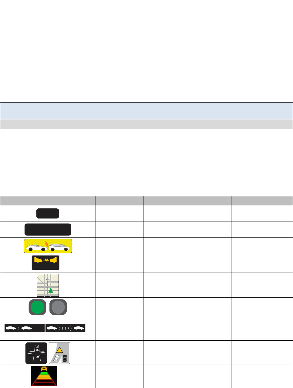
DVI DESIGN GUIDANCE VISUAL INTERFACES
6-2
Visual Display Type for Safety-related Messages
Introduction
Visual displays can be used to convey warnings or other information. There is a large range of potential information
that can be conveyed, including safety warnings related to other vehicle positions or states, road hazards such as
impending curves or merge situations, and driving performance such as fuel efficiency. This topic focuses on safety
warning messages related to external and internal vehicle state information (e.g., adaptive cruise control status), and
updates and expands the information presented in Campbell et al. [1]. Display type refers to the general format of the
presentation (e.g., digital, analog, text, etc.), as distinct from the specific implementation hardware (such as HUDs or
high head-down displays [HHDDs]) and location.
Design Goal: Select visual displays that convey information in a way that is consistent with the functional
requirements of the application.
Design Guidance
The research suggests that these visual display factors may be manipulated or used in support of the design goal:
• Continuous or graded analog displays with scale information (sometimes known as “looming displays”) are appropriate to
convey crash warning information or headway information at increasing levels of criticality.
• Symbolic or iconic representations can be used to add meaning to critical analog displays and do not require reading to
interpret.
• Spatial information is appropriate for showing intersection and lane change or merge warnings.
• Representational displays can be used to provide the driver with information regarding the functional status of vehicle
systems or states, relative to current conditions.
Examples of visual displays.
Visual Appearance Display Type Explanation Class of Information
27 mpg
Digital
Conveys information with
specific numeric or status values
Specific Value
Vehicle Stopped
Ahead
Text
Vehicle status requiring verbal
interpretation
Verbal Meaning
Icon or picture
Simple graphic requires no
verbal interpretation
Symbolic Meaning
WARNING
*
Icon or picture
with text
Simple graphic enhanced with
short text requiring interpretation
Symbolic and Verbal
Meaning
Gold A venue
Fiel d Ave nue
4
1st NE
42nd NE
43rd NE
Map
Conveys information about
location of own vehicle and
other traffic
Spatial
On Off
Digital
Conveys binary status
information about whether a
condition or state is true/active
Device State:
Presence or Absence
Minimum
Maximum
**
Functional
Conveys mode of operation and
status to aid driver interpretation
Device State
!
Representational
Conveys location and/or spatial
information about surroundings
Spatial
**
Continuous or
Graded
(Analog)
Conveys information on
continuous scale to show change
and rate (looming display)
Trend
* Adapted from Campbell et al. [1] ** Adapted from General Motors/Delphi [2]

VISUAL INTERFACES DVI DESIGN GUIDANCE
6-3
Discussion
Display types for safety-related systems should be selected based on the need for conveying specific information to
the driver. In particular, display types should be consistent with the type of information being communicated, the
manner in which drivers think about and use the information and—if appropriate—the nature of the driver response
associated with the message. This reflects an information processing principle called stimulus-response compatibility
in which more compatible mappings between displays and their desired response require fewer mental operations
from display to response [3] than less compatible displays. Overall, highly compatible display-response relationships
can lead to the development of a strong mental model of the system by the operator, as well as reduced response times
and fewer errors in responses than non-compatible display-response relationships. A simple example includes use of a
red indicator mounted on the left A-pillar that flashes when the driver activates the left turn signal or begins a lane
change when a vehicle is located in the driver’s left blind spot. Red is a stereotypical color that is accepted to indicate
danger, with flashing that indicates urgency. The leftward orientation of the indicator corresponds with the activation
of the left turn signal and indicates that the hazard is on the left side of the vehicle. These stimulus characteristics are
designed to elicit a response to abandon the lane change maneuver (i.e., steer away from danger).
There are few stand-alone studies of visual display types—they are generally evaluated in combination with other
alerting warning signals such as auditory or haptic. Moreover, there are very few in-depth and systematic
investigations exploring which display types are best for specific types of information. Current research about the
suitability of some display types is summarized below:
• Continuous or Graded Displays: Existing evidence suggests that graded-scale (“looming”) displays are
acceptable for imminent forward crash warnings (FCWs) [2] and lengthening headway [4].
• Representational Displays: Hatakenaka et al. [5] showed that drivers prefer a more realistic representational
map over a standard merge sign icon to provide merge warnings. Stanton et al. [6] showed that drivers
preferred and were better able to comprehend system state and detect adaptive cruise control (ACC) targets
with a radar-type display, despite being rated higher on mental workload.
• Icon Displays: Thoma et al. [7] showed that specific icon-based warnings facilitated comprehension in
difficult-to-detect visual scenes.
Design Issues
The functional purpose of information presentation should be the primary criterion for selecting the visual display
type. Continuous displays such as looming headway or safe speed indicators can be used for behavior modification,
although there is potential for driver distraction with an “always-on” and regularly changing display. For imminent
warnings such as lane change, intersection assist, and emergency braking, driver preference and limited performance
data indicate that spatial and graphically explicit representations are best. Forward collision warnings can be presented
on looming displays, and existing data suggest that simple head-up presentation is most appropriate (see Head-up
Displays, 6-16). With increasing use of driver-aiding technologies, use of representational displays to convey system
state will be important to alert drivers to situations where intervention with the automated system may be required. A
balance must be adopted between display content, interpretability, and frequency of occurrence.
Cross References
Designing Messages for Driver Comprehension, 5-2; Locating a Visual Display, 6-5; Using Color, 6-7; Temporal
Characteristics of Visual Displays, 6-13; Head-up Displays, 6-16
Topic References
1. Campbell, J. L., Richard, C. M., Brown, J. L., & McCallum, M. (2007). Crash warning system interfaces: Human factors insights and lessons
learned, final report (Report No. DOT HS 810 697). Washington, DC: National Highway Traffic Safety Administration.
2. General Motors Corporation & Delphi-Delco Electronic Systems. (2002). Automotive collision avoidance system field operation test, warning
cue implementation summary report (Report No. DOT HS 809 462). Washington, DC: National Highway Traffic Safety Administration.
3. Wickens, C. D. (1992). Engineering psychology and human performance (2nd ed.). New York: HarperCollins.
4. Dingus, T. A., McGehee, D. V., Manakkal, N., & Jahns, S. K. (1997). Human factors field evaluation of automotive headway
maintenance/collision warning devices. Human Factors, 39(2), 216-229.
5. Hatakenaka, H., Kanoshima, H., Aya, T., Nishii, S., Mizutani, H., & Nagano, K. (2008). Development and verification of effectiveness of an
AHS safe merging support service. Proceedings of the 15th World Congress on Intelligent Transport Systems and ITS America's 2008 Annual
Meeting [CD ROM].
6. Stanton, N. A., Dunoyer, A., & Leatherland, A. (2011). Detection of new in-path targets by drivers using stop & go adaptive cruise control.
Applied Ergonomics, 42(4), 592-601.
7. Thoma, S., Lindberg, T., & Klinker, G. (2009). Evaluation of a generic warning for multiple intersection assistance systems. In D. de Waard, J.
Godthelp, F. L. Kooi, & K. A. Brookhuis (Eds.), Human Factors, Security and Safety. Europe Chapter of the Human Factors and Ergonomics
Society (pp. 173-188). Maastricht, The Netherlands: Shaker.

DVI DESIGN GUIDANCE VISUAL INTERFACES
6-4
Locating a Visual Display
Introduction
The location of a visual display is a key factor affecting the ease with which drivers can obtain information.
Traditional dashboard designs are changing as new warning and information systems become available; appropriate
placement of the visual component of these systems will facilitate access to the information while reducing the impact
on the driving task. The main focus of this topic is the location of the display or displayed information on other
surfaces (such as mirrors), and minimizing the impact of glare to ensure readability.
Design Goal: Place the visual interface in a location that facilitates rapid extraction of information while
minimizing eyes-off-road glances and negative impacts on driving performance.
Design Guidance
The best available research on this topic suggests that this design goal can be met when:
−Critical displays for continuous vehicle control or critical warnings related to vehicle forward path are located within ± 15
degrees of the central line of sight but as close to the central line of sight as practicable. Messages that require immediate
detection should be located within 5 degrees of the forward view when possible [1], and 5 degrees to the right and 5
degrees down for messages on a HUD [2].
−Displays are placed in locations that are generally compatible with established expectations or with location cues from other
warnings, such as auditory or haptic.
−The display location is compatible with the desired response, such as a display in the mirror for alerts for looking to the
blind spot; a HUD that is used to direct attention to the forward view for critical warnings.
−The design and location minimizes glare from external sources or other displays in the vehicle (e.g., in the instrument panel
or under a protective cover).
−All messages or content presented on reconfigurable or multipurpose displays should be consistent with the above design
guidance. Specifically, both content and device location should be mutually compatible with line of site, driver
expectations, and response compatibility for all warning messages presented on the display.
The figure below shows examples of somepotential visual display locations that correspond with the design
information given above. The circled letters in the diagram point to the elements that illustrate each concept in the
design guidance above. Following are additional notes regarding the individual elements in the figure:
ⒷⒸ Displays located on the side mirrors and A-pillars provide information that is easily detected when checking
the mirrors or looking to the sides. Examples of applications that might use such displays include Blind Spot
Warning (BSW), Lane Change Warning (LCW), or Intersection Movement Assist (IMA).
Ⓑ Displays located in either corner of the rear-view mirror provide warning information to drivers who begin a
lane change maneuver by first checking the rear-view mirror.
ⒶⒸ Warnings presented on a HUD provide information about hazards directly ahead. The symbols on the HUD
are within ±15° for rapid detection.
Ⓓ Displays are shielded from glare by locating the display under a cowling.
Ⓔ Safety information presented on a multi-function display is appropriate for the display location. Both content
and location mutually support timely and accurate responses to associated hazards.
Examples of visual display locations.
Ⓐ
Ⓑ
Ⓒ
Ⓓ
Ⓔ

VISUAL INTERFACES DVI DESIGN GUIDANCE
6-5
Discussion
In general, locating the visual warning near the line of sight to the primary driving task will increase the likelihood
that it will be seen and will reduce the time needed to glance at that information [3]. An FCW, or other forward-
oriented warning, will be most effective when it is near the line of direct forward gaze toward the road ahead.
Similarly, an LCW or BSW will be more likely seen when it is near the line of sight to the side mirror as the driver
checks the mirror before initiating the lane-change maneuver. The Lerner, Kotwal, Lyons, and Gardner-Bonneau
preliminary guidelines [4] recommend that displays for non-directional hazards (e.g., low road friction) should be
located within 15 degrees of the driver’s line of sight of the roadway ahead, while ISO [1] recommends that critical
visual messages that require immediate detection should be located within 5 degrees of the driver’s line of sight. ISO
[5] also recommends that critical visual signals should be located as near to the driver’s line of sight as possible,
particularly if color is used. Color affects peripheral detection: green objects are not detected beyond 15 degrees from
the line of sight, while red and yellow/blue are not detected beyond 18 and 22 degrees, respectively. These findings
further support the recommendation that warning displays should not exceed 15 degrees of eccentricity.
Lerner, Kotwal, Lyons, and Gardner-Bonneau [4] recommends that the visual display should be located such that it
draws the driver’s gaze toward the hazard. They also recommend that a warning should induce an orienting response
that is compatible with the desired driver action and, importantly, that care should be taken to avoid eliciting a
response that is inconsistent with the desired driver action. This reflects an information processing principle called
stimulus-response compatibility in which more compatible mappings between displays and their desired response
require fewer mental operations from display to response [6] than do less compatible displays. Wege et al. [7] provide
information concerning driver glance changes in response to forward collision warnings; in particular, this group
found that forward glances were increased in response to warnings. Overall, highly compatible display-response
relationships can lead to the development of a strong mental model of the system by the operator, as well as reduced
response times and fewer errors in responses than non-compatible display-response relationships.
Design Issues
It can be generally assumed that drivers will expect key visual information to be presented in the general vicinity of
the instrument panel. Traditional vehicle health and status warning light displays tend to be placed in the instrument
panel. Location of directionally-specific warnings should correspond to the hazard, such that blind spot warnings
might be placed on either side mirror; similarly, intersection warnings may be directionally placed either on the A-
pillars with directional indications in the cluster or other selected location (e.g., HUD, HHDD). Side mirror placement
of warning information needs to accommodate likely glare issues; use of multiple element displays or flashing
provides a design approach to this issue.
Research [2] suggesting enhanced perception and preference for display locations 5 degrees below and to the right of
the central forward gaze suggests a potential standard location for HUD warning messages, should manufacturers
wish to converge on a standard. The tendency of drivers to seek information following a critical, unpredictable event,
despite the absence of displayed information, suggests that such displays be as close to the central gaze area as
possible. The finding also suggests that designers minimize the display of complex traffic or device state information,
as frequent use of these displays may alter driver glance patterns in undesirable ways.
Cross References
Multimodal Warning Messages, 4-4
Topic References
1. International Organization for Standardization. (1984). Development and principles for application of public information symbols. (ISO/TR
7239). Geneva: Author.
2. Yoo, H., Tsimhoni, O., Wantanabe, H., Green, P., & Shah, R. (1999). Display of HUD warnings to drivers: Determining an optimal location
(Report No. UMTRI-99-9). Ann Arbor: University of Michigan Transportation Research Institute.
3. Lind, H. (2007). An efficient visual forward collision warning display for vehicles. SAE World Congress. doi:10.4271/2007-01-1105.
4. Lerner, N. D., Kotwal, B. M., Lyons, R. D., & Gardner-Bonneau, D. J. (1996, January). Preliminary human factors guidelines for crash
avoidance warning devices (Report No. DOT HS 808 342). Washington, DC: National Highway Traffic Safety Administration.
5. International Organization for Standardization. (2005). Road vehicles—Ergonomic aspects of in-vehicle presentation for transport information
and control systems—Warning systems (ISO/TR 16352). Geneva: Author.
6. Wickens, C. D. (1992). Engineering psychology and human performance (2nd ed.). New York: HarperCollins.
7. Wege, C., Will, S., & Victor, T. (2013). Eye movement and brake reactions to real world brake-capacity forward collision warnings—A
naturalistic driving study. Accident Analysis and Prevention, 58, 259-270.doi:10.1016/j.aap.2012.09.013
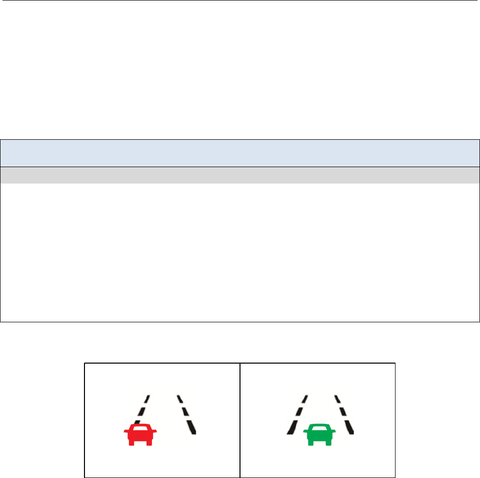
DVI DESIGN GUIDANCE VISUAL INTERFACES
6-6
Using Color
Introduction
Color is a characteristic of visual displays that can be useful for conveying meaning or urgency of alerting signals.
Color has certain advantages over text and symbols in terms of immediacy of recognition, and can serve to reinforce
meaning conveyed by other methods. Color is a complex variable, however, and issues of luminance, hue, contrast
and potential conflicts with other messages must be considered during design.
Design Goal: Use color to augment visual information presented in the displays to attract attention and/or to
convey the urgency of conditions or situations.
Design Guidance
The best available research on this topic suggests that this design goal can be met when:
• The color is associated with the level of warning:
−Red is normally associated with danger or critical situations
−Yellow is normally associated with caution
−Green is normally associated with normal operation; however, other considerations about warning conspicuity
may necessitate using a different color (see Design Issues on the next page).
• The colors that are used are compatible with symbols based on prior association, such as red for octagonal stop signs, and
yellow for triangular or diamond warnings.
• The quantity of colors used to code information is minimized; do not exceed 4 color codes.
• Color is used to create a “popout” effect in forward collision warnings to show the area of concern more distinctly from the
background scene.
• The following color contrast combinations are avoided: green/red, green/blue, yellow/red, yellow/blue, violet/red.
Example illustrating the two-stages of a warning display using color.
This image shows a hypothetical lane centering status display. The left
image indicates that the car is not centered in the lane. The non-centered
status is provided through position of the car on the lane display, as well as
through the red color of the car. The right image indicates that the car is
centered in the lane. The centered status is portrayed through showing the
car in the center of the lane display and through the green color of the car.

VISUAL INTERFACES DVI DESIGN GUIDANCE
6-7
Discussion
The stereotyped interpretation of certain colors can be used in combination with other warning signals or symbols to
convey or provide messages to the driver and, importantly, to promote appropriate and timely responses when
compatible with stereotypical stimulus-response pairings. The traditional association of the color red with “danger or
critical situation,” yellow with “caution,” and green with “normal” can be used to compliment auditory or haptic
signals, and to convey urgency [1]. While there have been some recent findings that the association of red with
“danger” is stronger than the association of yellow with “caution” [2], the context of driving would tend to reinforce
the stereotype interpretation based on the frequency with which such colors are encountered in the roadway
environment.
During development of the air bag warning label, NHTSA focus groups [3] did not associate orange with the word
“danger.” To reduce potential ambiguity, and to maximize perceived color distinctiveness, yellow should be used to
indicate a discrete CCW visual warning (however, see Design Issues below). The color green should not be used as a
CCW because it is associated with safe or normal operating conditions [1].
Color and shape combinations are used for specific types of warnings and traffic regulation on road signs, and use of
the same combinations for in-vehicle messages will help to maintain consistency between the road infrastructure and
in-vehicle information environments. For example, use of a diamond shaped symbol with yellow background and
black text is the accepted standard for warning signs [4], and application of these conventions for future safety system
messages (e.g., CV safety messages) is appropriate. Color-shape combinations can increase reaction times when signs
use shape as well as text because additional decision elements are used; thus if a shape is associated with a highly
stereotyped response, additional text may lead to longer reaction times [5]. Designers should avoid incompatible or
unconventional shape and color combinations, such as octagonal shape (having a conventional meaning of stop)
presented with a yellow background (having a conventional meaning of caution).
Color contrast can affect the perception of both the background and message content through complex interactions of
luminance and visual system effects. Avoidance of the specific combinations described in the design guidance above
will preclude this problem [1]. For messages requiring the presentation of text, green text has the advantage of being
at the frequency of maximum spectral sensitivity of the eye [6]. Similarly, green-yellow text (534 nm) best
accommodates both light- or dark-adapted eyes.
Design Issues
Color should not be used as the primary or exclusive means by which information is conveyed, but instead a
supplementary element or alternative cue to meaning. When approached in this way, designers can think of
appropriate location and symbol-shape means to convey the principal message content, and color can be used as a
means to more quickly draw attention and reinforce meaning through traditional associations. Furthermore, relying on
characteristics other than color will convey to drivers with color-blindness important information that might otherwise
be missed if color were used exclusively to communicate the information.
Keeping the number of color codes within human cognitive limits is important in the driving environment. Four colors
is the recommended maximum, as this corresponds generally to the warning levels of danger, warning, caution and
normal operation [1].
Cross References
Designing Messages for Driver Comprehension, 5-2; Locating a Visual Display, 6-4
Topic References
1. International Organization for Standardization. (2005). Road vehicles—Ergonomic aspects of in-vehicle presentation for transport information
and control systems—Warning systems (ISO/TR 16352). Geneva: Author.
2. Leonard, S. D. (1999). Does color of warning affect risk perception? International Journal of Industrial Ergonomics, 23, 499-504.
3. Federal Motor Vehicle Safety Standard (FMVSS) No. 208, Occupant crash protection [Docket No. 74-14; Notice 103], RIN 2127-AG14, to be
codified at 49 C. F. R. pt. 571. 208.
4. Federal Highway Administration. (2009). Manual on uniform traffic control devices, 2009 edition. Washington, DC: Author.
5. Tijus, C., Barcenilla, J., Cambon de Lavalette, B., & Maunier, J.-G. (2007). The design, understanding and usage of pictograms. In
G. Rijlaarsdam (Series Ed.) Vol. 21. Studies in Writing: Written documents in the workplace (pp. 17-31). Netherlands: Kluwer.
6. NASA Ames Research Center Color Usage Research Lab. (n.d.) Using color in information display graphics. Available at the NASA Ames
Research Center Color Usage Research Lab website at http://colorusage.arc.nasa.gov/index.php
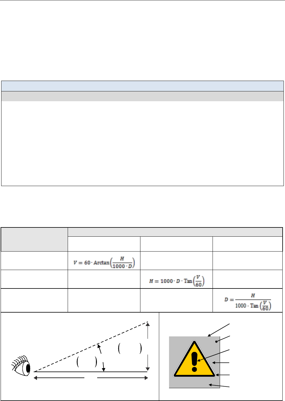
DVI DESIGN GUIDANCE VISUAL INTERFACES
6-8
Selecting Character Height for Icons and Text
Introduction
Text and graphic symbols in the driver-vehicle interface must be legible by all drivers under a large range of viewing
distances, viewing angles, and environmental conditions. Legibility goes beyond visibility or detection; it implies being able
to discern shape or character identity based on appearance. This topic addresses character height: including the visual angles
subtended by the icon, its graphical elements, text within the icon, and free-standing text.
Design Goal: Select sizes for text and icons in warning messages that support rapid legibility of the message.
Design Guidance
The best available research on this topic suggests that this design goal can be met when:
Icon Size:
Optimal visual angle of primary graphical elements
1
: 86 arcminutes
Minimum visual angle of primary graphical elements
1
: 41 arcminutes for time-critical applications
34 arcminutes for non-time-critical applications
Text Size (both within the icon and free-standing text—see the discussion):
Optimal height: 20 arcminutes
Minimum height: 16 arcminutes for time-critical applications
12 arcminutes for non-time-critical applications
1
Primary graphical elements provide the primary information needed to encode or detect the icon. Secondary graphical
elements provide additional context or clarifying information. Optimum visual angle refers to the angle at which the
primary graphical elements are both conspicous and legible. Minimum visual angle refers to the smallest angle at which
the primary graphical elements are legible but not necessarily conspicuous [1].
The table below provides equations for calculating the sizes of the icon, its graphical elements, text within the icon, and free-
standing text. Note that the equations assume the visual angle is measured in arcminutes, symbol height is in millimeters,
viewing distance is in meters, and the trigonometric functions (tangent and arctangent) accept and return values in degrees
rather than in radians. Appropriate conversion factors must be applied for different units.
Equations for calculating symbol height, visual angle, and viewing distance.
If Known…
Use These Equations for Calculating These Unknowns
Visual Angle (V)
in arcminutes
Symbol Height (H)
in millimeters
Viewing Distance (D)
in meters
Viewing Distance (D) and
Symbol Height (H)
— —
Viewing Distance (D) and
Visual Angle (V)
—
—
Visual Angle (V) and
Symbol Height (H)
— —
Definitions of Variables Used in the Equations
Eyepoint
V
Visual
Angle
Symbol
Height
(Distance from Viewer to Display)
D
H
H = Symbol height in millimeters
D = Viewing distance in meters (0.5–1.1 m)
V = Visual angle subtended in arcminutes
Figures adapted from Campbell et al. [2]
Definitions of Symbol Elements in an Icon
Border
Background
Secondary Graphical
Element
1
Text label
WARNING
Symbol
WARNING
Primary Graphical
Element
1

VISUAL INTERFACES DVI DESIGN GUIDANCE
6-9
Discussion
Icon Size: The design guidance above for icon size is consistent with the recommendations made by ISO/TR7239 [1], which
were based on a variety of research related to detection and resolution thresholds. The optimum visual angle suggested (86
arcminutes) is aimed at ensuring conspicuity, while the minimum visual angle (41 arcminutes) simply ensures legibility. It is
important to note that the recommendations made by ISO [1]—and therefore the design guidance on the previous page—are
based on the assumption that the icon will not be placed outside a 15 degree angular displacement from the central line of
the normal direction of user’s vision (see Locating a Visual Display, 6-4). ISO [3] specifies that the minimum size of
graphical symbols for use on equipment should be 1/100th their viewing distance, which corresponds to 34 arcminutes of
visual angle. The larger sizes in ISO [1] are recommended for time-critical applications in order to ensure both conspicuity
and legibility in the driving environment.
Text Size: ISO 15008 [4] recommends that character heights for in-vehicle display text should subtend at least 20 arcminutes
of visual angle, but 16 arcminutes is acceptable. Furthermore, the minimum visual angle for text should be no less than 12
arcminutes, but text of this size should be reserved for situations with only modest requirements for reading speed and
accuracy. More recent research by O’Day and Tijerina [5] verifies these values. They found that the highest accurate reading
rate occurred with the largest text height they tested (20 arcminutes) and the lowest accurate reading rate for text that
subtended 12 arcminutes. In addition, the greatest variability in accurate reading rate was associated with the smallest text.
Taken as a whole ANSI [6], Mourant et al. [7], Howell et al. [8], and Giddings [9] agree with the ISO [4] standard,
recommending a minimum character height of 16 arcminutes and optimal character heights for high legibility in the range of
20 to 30 arcminutes. The recommendation given in this design guidance reflects the specifications for text height found in
ISO [4] because it is an international standard that applies directly to the presentation of textual information in vehicle-based
applications.
It should be noted that the literature did not provide any information that suggested the size of text within an icon should be
different than the size of free-standing text in terms of legibility. Therefore, the design guidance above does not differentiate
between these implementations.
Design Issues
The size of in-vehicle displays is often limited by the available real-estate in the cab, which in turn limits the size of the
symbols presented on the displays. This limitation can result in a tradeoff between symbol size and legibility. When
designing in-vehicle displays, it is important to consider legibility when determining the sizes of symbols, especially in
safety-critical applications where the time available to read and interpret the symbols is limited. O’Day and Tijerina [5]
found that a wide variety of character heights can be legible if the character width and stroke width are carefully chosen.
Nevertheless, size is only one of the characteristics of graphical and textual symbols that affect legibility. The legibility of
icons and text is determined by factors such as the size, stroke width, contrast, and luminance [8, 10] (see Characteristics of
Legible Text, 6-10).
Cross References
Locating a Visual Display, 6-4; Using Color, 6-6; Characteristics of Legible Text, 6-10
Topic References
1. International Organization for Standardization. (1984). Development and principles for application of public information symbols. (ISO/TR
7239). Geneva: Author.
2. Campbell, J. L., Richard, C. M., Brown, J. L., & McCallum, M. (2007). Crash warning system interfaces: Human factors insights and lessons
learned, final report (Report No. DOT HS 810 697). Washington, DC: National Highway Traffic Safety Administration.
3. ISO 3461-1 (1988). General principles for the creation of graphical symbols, Part I: Graphical symbols for use on equipment. Geneva:
International Organization for Standardization.
4. ISO 15008. (2009). Road vehicles—Ergonomic aspects of transport information and control systems—Specifications and test procedures for
in-vehicle visual presentation. Geneva: International Organization for Standardization.
5. O’Day, S., & Tijerina, L. (2011). Legibility: Back to the basics. SAE International Journal of Passenger Cars—Mechanical Systems, 4(1), 591-
604.
6. ANSI/HFES 100-2007 (2007). Human factors engineering of computer workstations. Santa Monica, CA: Human Factors and Ergonomics
Society.
7. Mourant, R. R., & Langolf, G. D. (1976). Luminance specifications for automobile instrument panels. Human Factors, 18(1), 71-84.
8. Howell, W. C., & Kraft, C. L. (1959). Size, blur, and contrast as variables affecting the legibility of alphanumeric symbols on radar-type
displays (WADC Technical Report 59-536). Wright-Patterson Air Force Base, OH: Wright Air Development Center (DTIC No. AD-232 889).
9. Giddings, B. J. (1972). Alpha-numerics for raster displays. Ergonomics, 15(1), 65-72.
10. Carney, C., Campbell, J. L., & Mitchell, E. A. (1998). In-vehicle display icons and other information elements: Literature review (Report No.
FHWA RD 98 164). Washington, DC: Federal Highway Administration.

DVI DESIGN GUIDANCE VISUAL INTERFACES
6-10
Characteristics of Legible Text
Introduction
Legible text is made up of several elements that support the clear presentation of information that can be easily read
by the most drivers under most driving conditions. This topic summarizes information for font selection, width-to-
height ratios, and strokewidth-to-height ratios that have an effect upon text legibility.
Design Goal: Use clear and simple alphanumeric characters in support of message legibility.
Design Guidance
The best available research on this topic suggests that this design goal can be met when:
Font Characteristics and General Notes
• A clear, simple, and conventional typeface with the following characteristics is used:
−Open space inside and ample space between the letter forms to prevent blurring
−Highly distinguishable shapes
−Proportional horizontal spacing
−No extended serifs (if using a serif typeface)
−No internal patterning
• Abbreviations and signal words (words denoting the hazard) are presented in capital letters, or in mixed case when using
fonts that maximize the text’s visual angle.
• Messages are presented in mixed case, except for abbreviations and signal words.
Width-to-Height Ratio
• After selecting appropriate character heights, characters have a width-to-height ratio range of 0.6 to 0.85.
Strokewidth-to-Height Ratio Notes
• A strokewidth-to-height ratio range of 0.08 to 0.2 is acceptable, with 0.167 to 0.2 preferred for critical information.
• Optimum strokewidth for positive contrast (e.g., white text on a black background) is greater than that for negative contrast
(e.g., black text on a white background).
Note: This design guidance is closely related to the selection of appropriate character height (see page 6-8).
Comparison of text characteristics.
Characteristic Unacceptable Acceptable
Font
ABC
Patterned
ABC
Solid
Width-to-height Ratio
Ratio = .4
Ratio = .6
Strokewidth-to-height Ratio
Ratio = .04
Ratio = .167

VISUAL INTERFACES DVI DESIGN GUIDANCE
6-11
Discussion
General Font Type and Style. Most clear, simple, and conventional fonts will be legible as long as other parameters,
such as character size and contrast, are adequate [1]. Relevant standards such as ISO 15008 [2] do not prescribe a font
style (such as serif or sans serif). The use of styles outside of traditional serif/sans serif (such as script and block letter)
are not recommended, nor are fonts with internal patterns or extended serifs [3, 1]. A driving simulator assessment of
different fonts found that visual demand level, total glance time and frequency improved with highly distinguishable
shapes, varied horizontal proportions to add distinguishing characteristics, and both greater open space inside, and
ample space between, the letter forms to prevent blurring [4].
Use of all capital letters for abbreviations and signal words (words denoting the hazard level, such as caution or
danger) is appropriate, as common signal words are viewed and processed as icons and not text [5]. Mixed case
presentation can assist with the faster word recognition, however for safety critical messages the larger visual angle of
capital letters is preferable. Research examining the use of the font “Clearview” found increasing the size of lowercase
letters while keeping the same overall space use of lowercase letters, can aid legibility of road signs [6]. Presentation
maximizing the visual angle of signal words may reduce the need for all capital letters.
Width-to-height refers to the ratio of the width to the height of the character. There is general agreement amongst
sources for these values. Most recommend a width-to-height ratio ranging from 0.6 to 0.85 [2, 3, 7], although ISO
standards allow a wider range provided that other factors such as proportional spacing are optimized [2]. Note this
requires basing calculations on non-single stroke characters (i.e., characters other than the numeral “1” or letter “I”).
Strokewidth-to-height refers to the ratio of the line (stroke) thickness to the height of the character; smaller
strokewidth to height ratios result in skinnier appearing letters. Sources of guidance generally range from a minimum
acceptable value of 0.08 to a maximum of 0.2 [2, 3, 7]. Larger strokewidths are preferred when information criticality
or dynamicity increases. Greater strokewidths are required for off-axis viewing, difficult lighting conditions [7].
A specific concern is the presentation of white against a black background (negative polarity). This can lead to
irradiation effects, where lighter features appear to spread into the adjacent background, especially for highly
illuminated displays and/or dark adapted viewing [8]. Optimum strokewidth-to-height ratios for black characters on a
white background (0.125 – 0.167) are lower than those for white characters on a black background (0.1 – 0.125).
Design Issues
It is important to select an appropriate character height (see also page 6-8). Many aspects discussed in this section
follow the selection of character height. O’Day and Tijerina [9] examined multiple font characteristics and identified
fonts with large character heights, wide widths, and narrow strokewidths as having acceptable reading accuracy across
age groups. The reader is referred to this work for further discussion of these complex relationships.
Cross References
Selecting Character Height for Icons and Text, 6-8
Topic References
1. Wogalter, M. S., & Leonard, S. D. (1999). Attention capture and maintenance. In M. S. Wogalter, D. DeJoy, & K. R. Laughery (Eds.)
Warnings and Risk Communication (pp. 113-138). Boca Raton, FL: CRC Press.
2. ISO 15008 (2009). Road vehicles – Ergonomics aspects of transport information and control systems – specifications and test procedures for
in-vehicle visual presentation. Geneva: International Organization for Standardization.
3. Woodson, W. E., Tillman, B., & Tillman, P. (1992). Human factors design handbook (2nd Ed.). New York: McGraw-Hill Professional.
4. Reimer, B., Mehler, B., Dobres, J., Coughlin, J. F., Matteson, S., Gould, D., … & Levantovsky, V. (2014). Assessing the impact of typeface
design in a text rich automotive user interface. Ergonomics. doi:10.1080/00140139.2014.940000
5. Frascara, J. (2006). Typography and the visual design of warnings. In M. S. Wogalter (Ed.), Handbook of Warnings (pp. 385-406). Mahwah,
NJ: Erlbaum.
6. Garvey, P. M., Pietrucha, M. T., & Meeker, D. (1997). Effects of font and capitalization on legibility of guide signs. Transportation Research
Record: Journal of the Transportation Research Board, 1605, 73-79.
7. United States Department of Defense. (1996). Technical architecture framework for information management, Volume 8: DoD Human
Computer Interface style guide, Version 3.0. Washington, DC: Author.
8. Piepenbrock, C., Mayr, S., & Buchner, A. (2014). Positive display polarity is particularly advantageous for small character sizes: Implications
for display design. Human Factors, 56(5), 942-951. doi: 10.1177/0018720813515509
9. O'Day, S., & Tijerina, L. (2011). Legibility: Back to the basics. SAE International Journal of Passenger Cars: Mechanical Systems, 4(1), 591-
604.
10. Pelli, D. G., Tillman, K. A., Freeman, J., Su, M., Berger, T. D., & Majaj, N. J. (2007). Crowding and eccentricity determine reading rate.
Journal of Vision, 7(2):20. Doi: 10.1167/7.2.20

DVI DESIGN GUIDANCE VISUAL INTERFACES
6-12
Temporal Characteristics of Visual Displays
Introduction
The temporal characteristics of visual warnings involve the use of flashing, blinking and sequential illumination to
simulate motion in order to draw attention toward a particular visual display. The use of temporal characteristics, such
as flash and motion, takes advantage of features of the human visual system that are especially sensitive to these
features. This topic covers the design of in-vehicle warnings using temporal and movement features.
Design Goal: Use changes in the temporal characteristics of visual displays, such as flashing, blinking or
apparent motion, to command visual attention.
Design Guidance
The best available research on this topic suggests that this design goal can be met when:
• A higher flash rate is used for more urgent situations—optimal rate is 3-4 Hz.
• Multiple flash mode (rapid pulses of flash for each flash cycle) is used for more urgent situations.
• Flash rate and duty cycle are adjusted as-needed to ensure driver comprehension of warning content.
• Warnings are presented in appropriate temporal proximity to the dangerous situation to elicit desired response but not a
nuisance alarm.
• Flashing is used for important, suddenly-occurring situations.
• Sequential illumination is used to convey motion and/or direction, but keep text stationary.
• Other motion cues such as bouncing or zooming are not used as they may unnecessarily increase driver eyes-off-road time.
Examples of flash rate and duty cycle.
Flash Rate (Frequency): The number of
flashes per second. Example (a) shows lower
flash rate (one flash per second), and
example (b) shows higher flash rate (four
flashes per second).
A high flash rate can be used to convey high
urgency.
0 0.5 1 1.5 2 2.5
Off
On
Time (seconds)
b) High Frequency
1s
1 2
3
4
0
0.5
1
1.5
2
2.5
Time (seconds)
a) Low Frequency
1s
1
Off
On
Duty Cycle: The percent of time within a cycle
that the sign is in the “on” state. The example
shows a signal with 80% duty cycle (“on” for
0.8s and “off” for 0.2s).
A higher duty cycle can be used for presenting
icons with accompanying text in order to
provide sufficient time for the driver to read the
text.
80% Duty Cycle
On
Off
0 1 2 3 4 5
Time (seconds)
0.8s
1s
Complex Flash: Presentation of multiple
flashes with varying “on” and “off” times. The
example shows two one-second bursts with
four pulses per burst. Each burst is separated by
one second of “off” time.
Complex flashes can be used to further increase
perception of urgency.
Off
On
Time (seconds)
0 1 2 3 4

VISUAL INTERFACES DVI DESIGN GUIDANCE
6-13
Discussion
Use of flashing signals is a standard practice in warning system design [1]. The basic parameters of a flashing warning
are the frequency, contrast, and duty cycle. Frequency refers to the number of times per second the signal flashes; a
considerable amount of human factors research suggests that for conveying urgency, an optimal flash rate is 3-4 times
per second [1, 2]. It is possible also to modulate each flash within a cycle via a multiple “fast flash” mode—this has
been found to further increase perception of urgency [2]. Contrast refers to the change in illumination between the
“on” and “off” portions of the flash. The duty cycle of the flash period refers to the relative amount of “on” and “off”
time for the flashing signal—this is a relevant parameter if symbolic and verbal information are conveyed on a
flashing warning because drivers require sufficient “on” time to view the information.
The presentation of warning information in appropriate temporal proximity to the hazard is important for commanding
attention, eliciting the necessary response by the driver, and to avoid nuisance alarms by warning for conditions too
early. The beneficial effects of early (1.5 s prior to predicted impact) versus late (1.0 s prior to predicted impact)
warnings have been demonstrated [3]. Warning timing is discussed in Providing Forward Collision Warnings that
Accommodate Driver Brake Reaction Time (page 4-8).
Sequential illumination of display elements can be used to create apparent motion, which can convey directional
information pertinent to warning systems. This can be useful for intersection management alerts, for example, in
which approaching vehicles from the left or right can be signaled via sequential illumination of elements on a HUD or
central instrument cluster. ISO [1] provides examples of movement in association with icons to convey dangerous
situations such as emergency vehicles, icy roadways, etc. Apparent motion should only be applied to icons or
symbols; text should be stationary to reduce potential distraction or implied meaning associated with text motion.
Motion cues may affect cognitive load. Doshi et al. [4] used a number of motion cues in a HUD, including bouncing
triangular warning signs, zooming warning signs and moving graphical indicators with a bounce to show excessive
speed. The results suggested that motion without contextual information about speed led drivers to spend more time
looking down at the instrument cluster to determine why the alert was being provided than they did with no alert.
Design Issues
Flashing and motion can be compelling visual warnings, and are appropriate for use in imminent danger situations if
the warning can be provided in appropriate temporal relationship to the hazard so that nuisance alarms are not
perceived. The increasing ease of presenting visual effects such as zooming and bouncing of visual elements lead to
an expanded interpretation of the “flash” concept. Type of motion, however, should not be used as a code in and of
itself; instead, supplementary information should be provided (such as current speed or speed limit), without requiring
the driver to visually refer to other instruments or displays.
Cross References
Multimodal Warning Messages, 4-4, Providing Forward Collision Warnings that Accommodate Driver Brake
Reaction Time, 4-8; Locating a Visual Display, 6-4; Display Glare, 6-14
Topic References
1. International Organization for Standardization. (2005). Road vehicles—Ergonomic aspects of in-vehicle presentation for transport information
and control systems—Warning systems (ISO/TR 16352). Geneva: Author.
2. Chan, A. H. S., & Ng, A. W. Y. (2009). Perceptions of implied hazard for visual and auditory alerting signals. Safety Science. 47, 346-352.
3. McGehee, D. V., Brown, T. L., Lee, J. D., & Wilson, T. B. (2002). Effect of warning timing on collision avoidance behavior in a stationary
lead vehicle scenario. Transportation Research Record: Journal of the Transportation Research Board, 1803, 1-7.
4. Doshi, A., Cheng, S. U., & Trivedi, M. M. (2009). A novel active heads-up display for driver assistance. IEEE Transactions on Systems, Man,
and Cybernetics—Part B: Cybernetics, 39(1), 85-93.
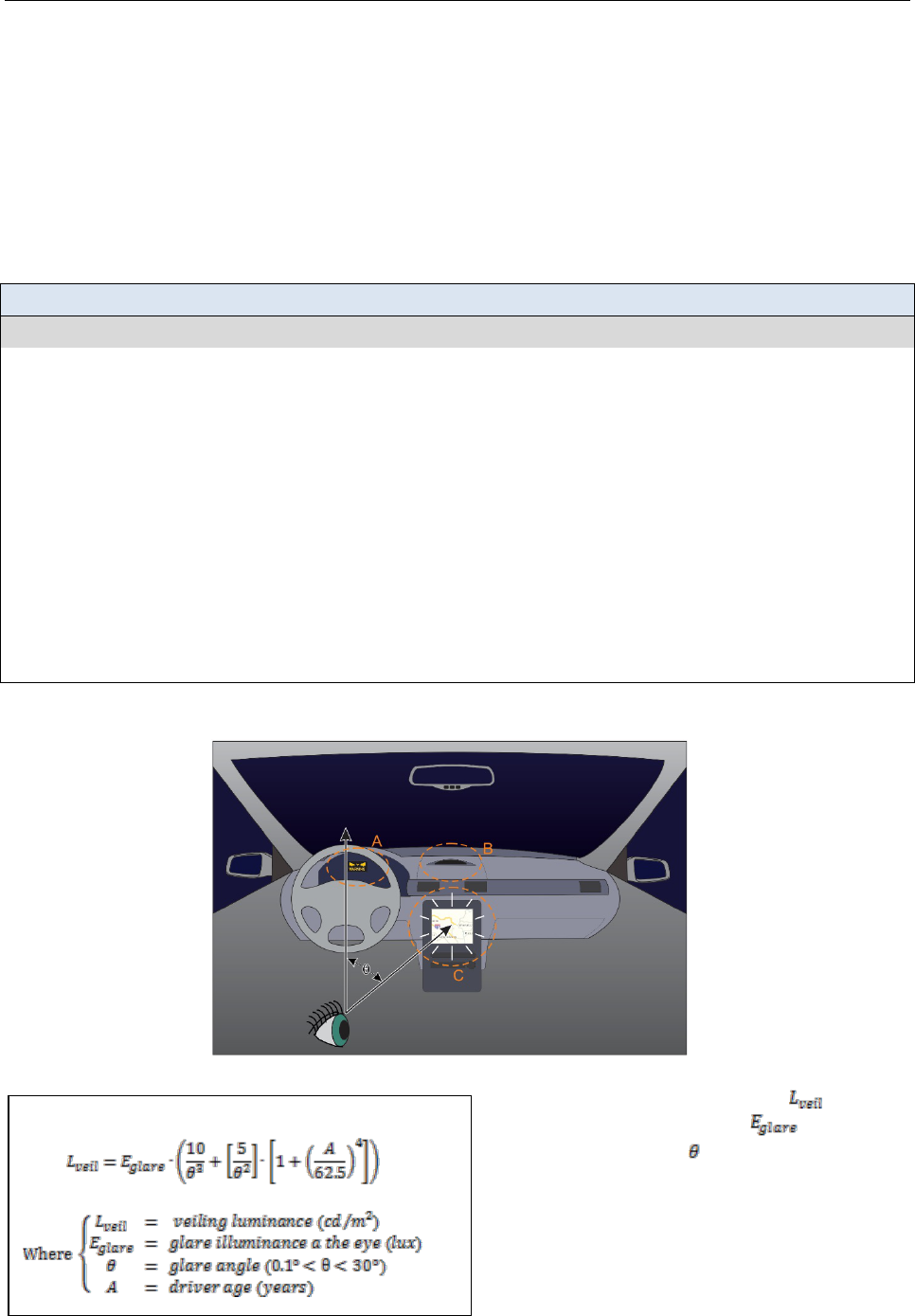
DVI DESIGN GUIDANCE VISUAL INTERFACES
6-14
Display Glare
Introduction
Glare on visual displays can originate from a variety of sources in the driving environment and can make visual
displays difficult to read. In addition, light emanating from displays can be glaring at night causing discomfort, or in
some conditions, reduced visibility of the external driving environment. This topic discusses ways to mitigate both the
reduced legibility and conspicuity of display information due to glare on the display and the reduced visibility of the
environment and increased physical discomfort caused by glare from in-vehicle displays.
Design Goal: Minimize glare, both on and from visual displays.
Design Guidance
The best available research on this topic suggests that this design goal can be met through the following strategies:
Mitigating glare on the display in daytime driving:
• Provide sufficient display luminance and use high contrast display technologies to ensure adequate contrast.
• Place safety-critical displays in a location that minimizes exposure of the display sunlight.
• Use designs or locations that provide shading, such as a cowling or an inset bezel.
• Use anti-glare coatings or films to filter incoming light and reduce glaring reflections from the display.
• In some configurations, smaller display sizes can be easier to shade; however, care must be taken to ensure that other
important design considerations, such as symbol size and conspicuity, are not compromised.
Mitigating glare that emanates from the display while driving in darkness:
• Provide a control that allows drivers to adjust the display intensity but do not allow drivers to turn the display off completely.
• Use light sensors to automatically reduce display luminance in darkness.
• Display content using a dark background to minimize the luminance emanating from the display.
• Locate and orient the display to minimize reflections on windows.
• Consider locating non-safety-critical displays in highly eccentric locations relative to the forward gaze (e.g., center stack) to
increase the glare angle. Do not use this approach for critical safety messages.
Examples of mitigations for glare incident on and emanating from the display.
Glare on the Display
in Daylight
A. Display embedded
in the instrument
panel to protect
from sunlight
B. Display mounted in
recess above the
center stack
A & B. Display
luminance is
sufficient to ensure
adequate contrast
Glare from the Display
in Darkness
C. Display intensity is
adjustable to allow
drivers to control
amount of luminance
• The CIE veiling luminance model to the left
shows that veiling luminance ( ) increases
as (1) glare illuminance (
) increases and
(2) glare angle (
) decreases.
• Increased veiling luminance results in reduced
visibility
Adapted from CIE 146:2002 [1]. Used with permission.

VISUAL INTERFACES DVI DESIGN GUIDANCE
6-15
Discussion
Glare on the Display: Intense light, such as sunlight, that falls on a visual display superimposes a uniform luminance onto the
display, essentially “filling in” the darker areas of the displayed image, thereby reducing image contrast (i.e., the luminance
ratio of the light to dark areas is reduced). The image on the display becomes increasingly difficult to read as the contrast
decreases, until eventually the image can no longer be detected [1, 2]. This reduction in contrast could be a particular problem
for applications that rely on visual displays to present time-critical safety messages because lower contrast can increase
drivers’ reaction times or they may not see the display altogether.
Glare from the Display: Glare from a visual display occurs when the intensity of the display within the visual field is
substantially greater than the visual adaptation level, causing physical discomfort or pain (discomfort glare) and/or reduced
visibility (disability glare). A portion of the light entering the eye is scattered in the transparent media of the eye (i.e., cornea,
lens, and vitreous fluids) and by the tissues in the ocular fundus [3]. Some light also diffuses through the sclera and iris
tissues. The scattered light superimposes a uniform veiling luminance onto the retinal image, reducing its overall contrast. If
the contrast of the image falls below the contrast threshold for visibility under these conditions, it will be rendered invisible
[1]. Veiling luminance is influenced primarily by the intensity of light, the surface area of the lighted areas of the display, and
the angle at which the glaring luminance enters the eye.
Design Issues
Glare on the Display: Preventing glare from sunlight falling on an in-vehicle display can be extremely challenging to
designers. Kiefer et al. [4] recommend that one way to mitigate glare on a display is to provide sufficient luminance from the
display in daytime driving to ensure adequate contrast. High-contrast display technologies can also reduce the effects of glare
on the display. Wreggit et al. [5] found that an electroluminescent display provided sufficient contrast for legibility, and
drivers reported no washout or glare from sunlight. Because vehicles are not stationary, it may be difficult (or perhaps
impossible) to locate a display in a location that will never receive direct sunlight. Nevertheless, placing the display in the
instrument panel, in a custom recess, or within a shading bezel, etc., can help reduce exposure to glaring light. In some
configurations, smaller displays may be easier to protect from direct light because they have less surface area to shade;
however, it is important to ensure that other aspects of DVI design (e.g., text and icon legibility, conspicuity, etc.) are not
compromised when using a smaller display.
Glare from the Display: Several mathematical models have been developed that estimate the amount of veiling luminance
developed by a glare source [e.g., 1, 3, 6]. These models show that veiling luminance is directly proportional to intensity and
inversely proportional to the angle at which glaring luminance enters the eye relative to the forward gaze. Thus, there are two
primary solutions for reducing the effects of glare emanating from in-vehicle displays: (1) reduce the amount of light
emanating from the display and/or (2) increase the eccentricity of the display location. A preferred approach for reducing the
effects of glare from displays is to provide a control that is used to adjust the display intensity. This can be a manually
operated control that drivers manipulate or an automated control that adjusts display luminance based on sensors that detect
ambient light levels. Regardless of how the control is implemented, however, the amount of control provided should be
limited to prevent drivers from turning off the display completely [4]. Another way to reduce display luminance is to present
content on a dark background in order to minimize the overall surface area of high-intensity portions of the image. Finally,
locating the display further into peripheral vision can reduce the effects of glare, but with important tradeoffs with regard to
reductions in warning conspicuity and detection. Relevant implications associated with location of the display are discussed in
Locating a Visual Display, pp 6-4, 5.
Cross References
Locating a Visual Display, 6-4
Topic References
1. CIE 146:2002. (2002). CIE equations for disability glare. Vienna, Austria: International Commission on Illumination.
2. ANSI/HFES 100-2007 (2007). Human factors engineering of computer workstations. Santa Monica, CA: Human Factors and Ergonomics
Society.
3. Adrian, W., & Bhanji, A. (1991). Fundamentals of disability glare: A formula to describe stray light in the eye as a function of glare angle and
age. Proceedings of the First International Symposium on Glare (pp. 185-193). New York: Lighting Research Institute.
4. Kiefer, R., LeBlanc, D., Palmer, M., Salinger, J., Deering, R., & Shulman, M. (1999). Development and validation of functional definitions and
evaluation procedures for collision warning/avoidance systems (Report No. DOT HT 808 964). Washington, DC: National Highway Traffic
Safety Administration.
5. Wreggit, S. S., Powell, J., Kirn, C., & Hayes, E. (2000). Human factors evaluation of the truck productivity computer’s electroluminescent
display (Paper No. 2000-01-3409). Warrendale, PA: SAE International.
6. Farber, E., & Matle, C. (1989). PCDETECT: A revised version of the DETECT seeing distance model. Transportation Research Record:
Journal of the Transportation Research Board, 1213, 11-20.

DVI DESIGN GUIDANCE VISUAL INTERFACES
6-16
Head-up Displays
Introduction
HUDs have the potential to provide drivers with critical information while minimizing glance times away from the forward
roadway scene. This can increase the speed of information access by the driver by reducing eye movement and visual
accommodation time. HUDs have been used and studied extensively in aviation [1] and, as costs have reduced, are being
used more frequently in automobiles. HUDs also have the potential to expand display space within the vehicle. Application
of the technology should proceed conservatively, however, while impacts of factors such as potential distractions and driver
individual differences are further evaluated. Designers should consider the necessity of the information with regard to the
current driving situation when deciding what information to provide via HUD. Nevertheless, there exists a sufficient body of
information on HUDs—both in aviation and, more recently, in automotive applications—to establish design guidance.
Design Goal: Use HUDs to present simple indications of critical safety situations in the driver’s forward view.
Design Guidance
The best available research on this topic suggests that this design goal can be met when:
• HUDs can be used to present critical forward field of view warnings that would not be appropriate for head-down displays,
such as location of hazards for imminent FCWs and intersection hazards.
• Information presented in the HUD is interpretable within the HUD and does not require visual reference to other head down
displays.
• Information relevant to the driving situation is prioritized over presenting non-driving related information.
• The use of continuously presented stable-value information on a HUD is minimized.
• The use of symbols, text, or indicators that continuously change in value, or are redundant with road sign information is
limited.
• The HUD is located 5 degrees to the right and 5 degrees below the center line of driver view.
• The HUD is adjustable to allow drivers with polarized sunglasses to see the information clearly.
Example of a HUD.
HUD providing a warning.
• Only present during alert
• Used in conjunction with other modalities
• Removed after scenario resolved
HUD providing navigation information.
• Only provides driving/navigation relevant
information
• Does not provide stable-value information
(e.g., “Navigation Active”)
• Minimal number of dynamic elements
• Driver may disable if desired

VISUAL INTERFACES DVI DESIGN GUIDANCE
6-17
Discussion
HUDs have been studied in a number of different configurations and conditions, including comparisons with HHDDs,
traditional instrument clusters, and under various traffic load, secondary task, and hazard detection conditions. The clearest
result to emerge from this work is the advantage of the HUD in reducing braking time and increasing warning detections for
critical road events [2, 3]. Lind [2] compared a collision warning HUD displayed in the central driver view in response to
critical road hazards, with displays on the upper dashboard (HHDD), instrument cluster, and a steering wheel array of light
emitting diodes. This study involved a strictly visual HUD, i.e., there was no associated auditory cue. The salient attentional
signal was flashing of the LED matrix 4 Hz for 1.2s. This type of HUD is different than more conventionally designed
HUDs, which may employ alphanumerics, graphics, or icons.
The balance of evidence suggests that under test conditions, HUDs or HHDDs that are located above the instrument cluster
tend to improve driver performance as measured by vehicle headway distance, response time to critical events, lane keeping
and other measures of driving behavior [2, 4, 5, 6]. Other work suggests that the shifting locus of attention between HUD
and roadway interacts with driving workload in complex ways [7]. Liu [7] also demonstrates a learning effect, such that
early use of the HUD results in inferior driving performance compared to later use within the experimental sessions.
HUD content is a complex issue—most of the experimental evaluations have addressed questions of driving performance,
braking response and event detection. Some studies have evaluated multi-element displays intended for collision warning
and low visibility conditions [4] while another [8] compared symbolic versus scale displays for speed control. This latter
study illustrated the detrimental effect of displaying an over-speed warning on the HUD, without also including current
speed—in this case, drivers had to take their eyes off the road to glance at the speedometer.
Location of a HUD is the variable with the most consistent findings across a range of experiments, which suggest that the
HUD should be located approximately 5 degrees to the right and 5 degrees below the driver’s central visual focus [9]. There
is some evidence that HUDs are preferred by drivers in simulator studies, and they yield better driving performance and
information detection than a head-down display [4]. Horrey et al. [5] showed that downward glances were increased in the
post-threat period for unpredictable traffic events. This was interpreted as drivers seeking further information from the
display, which was already turned off, to comprehend the nature of the just-past hazard. Thus, eyes-off-road may occur in
unanticipated ways with advanced warning and control systems.
Design Issues
The specific design implementation of a HUD is a complex mix of design philosophy, attentional theory, and pragmatics,
and determines the overall effectiveness of the final display. As a platform for safety messages, HUDs are most appropriate
for critical forward collision and intersection warnings that are placed in or near the center of the driver’s visual field. This
approach reserves the HUD location for critical information that is unlikely to be extraneous or distracting. Other
approaches such as vehicle speed monitoring and driver aiding systems are more complex, and involve a much larger range
of display elements and properties. While there seems to be no detrimental effect of these types of displays in laboratory and
limited on-road testing, they may have the effect of reducing the impact or salience of critical forward warnings, or worse,
lead to an excessively cluttered field of view.
Cross References
Display Glare, 6-14
Topic References
1. Prinzel, L. J., & Risser, M. (2004). Head-up displays and attention capture (NASA/TM-2004-213000). Available at the NASA website at
http://naca.larc.nasa.gov/search.jsp?R=20040065771&qs=N%3D4294966788%2B4294724598%2B4294323833
2. Lind, H. (2007). An efficient visual forward collision warning display for vehicles. SAE World Congress. doi:10.4271/2007-01-1105
3. Kiefer, R. J. (1996). A review of driver performance with head-up displays. Third World Congress on Intelligent Transport Systems .
Washington, DC: ITS America.
4. Charissis, V., & Papanastasiou, S. (2010). Human-machine collaboration through vehicle head up display interface. Cognition, Technology and
Work, 12(1), 41-50.
5. Horrey, W. J., Wickens, D. D., & Alexander, A. L. (2003). The effects of head-up display clutter and in-vehicle display separation on
concurrent driving performance. Proceedings of the Human Factors and Ergonomics Society 47th Annual Meeting. 1880-1884.
6. Perez, M. A., Kiefer, R. J., Haskins, A., & Hankey, J. M. (2009). Evaluation of forward collision warning system visual alert candidates and
SAE J2400. SAE International Journal of Passenger Cars—Mechanical Systems. 2(1). 750—764.
7. Liu, Y-C. (2003). Effects of using head-up display in automobile context on attention demand and driving performance. Displays, 24(4-5), 157-
165.
8. Doshi, A., Cheng, S. U., & Trivedi, M. M. (2009). A novel active heads-up display for driver assistance. IEEE Transactions on Systems, Man,
and Cybernetics—Part B: Cybernetics, 39(1), 85-93.
9. Yoo, H., Tsimhoni, O., Wantanabe, H., Green, P., & Shah, R. (1999). Display of HUD warnings to drivers: Determining an optimal location
(Report No. UMTRI-99-9). Ann Arbor: University of Michigan Transportation Research Institute.

DVI DESIGN GUIDANCE VISUAL INTERFACES
6-18

AUDITORY INTERFACES DVI DESIGN GUIDANCE
7-1
Chapter 7. Auditory Interfaces
This chapter provides guidance for the design of auditory interfaces. Auditory interfaces are useful
for capturing and directing drivers’ attention and for presenting information to drivers when they
are not attending to a visual display. Consequently, these interfaces are particularly useful for
presenting safety messages to drivers. Auditory signals can be used to convey three forms of
information that are important for collision warning systems (Catchpole, KcKeown, &
Withington, 2004). First, urgency cues provide information regarding the criticality of the
situation or how quickly drivers need to respond to the warning. Second, location information
identifies where the hazard is located or where it is coming from. Third, the semantic meaning
associated with the signal provides information to the driver about what is happening or what
actions to take in order to avoid a crash. Although all three forms of information do not
necessarily need to be included in a single collision avoidance application, each of these
components can provide useful information for facilitating rapid and correct responses.
Auditory signals can be effective for presenting collision warnings because they can be perceived
regardless of the direction of visual attention. These signals can be very effective in warning
situations when they are salient, appropriately obtrusive, and their meaning can be understood.
Various characteristics of auditory warning signals can be modulated to affect the warning’s level
of salience and obtrusiveness as well as the perception of urgency, and the type of signal used can
facilitate comprehension of the information being displayed.
There are design tradeoffs, however, that need to be considered in order to avoid unwanted side
effects. Salient, obtrusive sounds can be annoying if they are presented often, too loudly, or if their
characteristics are perceived as annoying. Yet sounds that are not obtrusive or loud enough may go
unnoticed. Also, the meaning of some auditory signals, such as speech messages and auditory
icons (auditory signals that sound like a real object or event, such as a screeching tire), can be easy
to understand, while the meaning of other types of sounds, such as pure tones, must be learned.
In general, key literature in this area suggests that the auditory modality be used primarily for
imminent warnings. Because they can be perceived as annoying, and they are likely to occur
frequently, auditory warnings are generally not appropriate for use in cautionary warnings.
Auditory warnings, however, can be highly effective as imminent warnings, particularly as the
final stage of a two-stage or graded warning system.
Topics included in this chapter:
• Auditory Display Type
• Perceived Urgency of Auditory Warnings
• Perceived Annoyance of Auditory Warnings
• Loudness of Auditory Warning Signals
• Distinctiveness of Warning Messages
• Using Localization Cues to Indicate Direction
• Presenting Warnings Using Speech Messages

DVI DESIGN GUIDANCE AUDITORY INTERFACES
7-2
Auditory Display Type
Introduction
This topic provides information for choosing the type of auditory signal (simple tone, earcon, auditory icon, or speech
message) that will provide effective auditory warnings under expected conditions or that will best augment other
necessary visual information.
Design Goal: Select an auditory display type that facilitates drivers’ understanding of the hazard and supports
appropriate and timely responses.
Design Guidance
The literature provides suggestions for selecting an auditory display type and properties to support the design goal.
Table A below provides definitions and examples of the auditory signals used for warnings. Table B shows the
properties of each warning type and suggests the types of applications or situations for which the sounds may be
suited. However, this does not imply that a given warning type cannot be used successfully for applications other than
those suggested, provided the signal includes characteristics that are consistent with the relevant driving situation.
Table A. Definitions of display types.
Display Type Explanation Example
Simple Tones Single or grouped frequencies presented simultaneously. Sine wave or square wave
Earcons Abstract musical tones that can be used in structured
combinations to create auditory messages. Sometimes
referred to as complex tones.
“Ding” or two-tone chimes
Auditory Icons Environmental sounds that intuitively convey information
about the object or action they represent.
Car horn or skidding tire
sounds
Speech Messages Voice messages that add information beyond pure sound. “Danger”
Table B. Display types, their properties, and suggested uses.
Display Type Properties Suggested Uses
Simple Tones
• High flexibility for conveying various levels
urgency
• Can be highly salient and obtrusive [1]
• Can be annoying [2, 3, 4]
• Meaning is not inherently known and must be
learned [4]
• Highly time-critical messages, such as
imminent collision warnings
• Situations that require immediate action
Earcons
• Friendlier and less obtrusive sounds
• Meaning is not inherently known and must be
learned [2]
• Cautionary warnings*
• Drawing attention to visual status
information
Auditory Icons
• Can by highly salient and obtrusive [5, 6]
• Meaning can be easily understood [5]
• Can lead to false reactions [6]
• Can be highly annoying [7]
• Imminent collision warnings
• Infrequent alerts
Speech
Messages
• Meaning can be easily understood [2]
• Takes time to receive the complete message
[1, 8]
• Can be highly annoying if presented
frequently [4]
• Less time-critical messages
• Conveying complex information
• Situations that require more detailed
information
*Although auditory warnings are not generally recommended for cautionary warnings because of the potential for annoyance, under appropriate
conditions (e.g., with infrequent presentation and lower-urgency characteristics), earcons could potentially be useful in this application.

AUDITORY INTERFACES DVI DESIGN GUIDANCE
7-3
Discussion
Simple tones are good for gaining the attention of the driver and, if properly implemented, can be used to warn of an
imminent danger effectively. Because they are abstract, tones can be used in a variety of applications by adjusting
their characteristics to convey the proper level of urgency, obtrusiveness, and salience. Simple tones have been shown
to produce shorter reaction times than speech messages when used in conjunction with a visual display (e.g., Kiefer
et al. [1]). However, tones can potentially be considered annoying and, therefore, might be best-suited only for
conditions in which getting the drivers’ attention is critical [2, 3, 4]. Other drawbacks of simple tones include the fact
that their meaning is not inherently known and must be learned by the driver and that an unfamiliar tone could
produce an inappropriate response [4].
Earcons often can be used to generate sounds that are friendlier and less obtrusive, which are useful properties for
cautionary warnings and low-urgency applications, such as drawing attention to a visual status display. However, like
simple tones, earcons are limited because their meaning is not apparent and must be learned. Consequently, they are
not a good choice for presenting critical, time-dependent information to the driver [2, 4].
Auditory icons are most effective when they can be mapped to everyday, naturally-occurring sounds. These sounds
may convey higher-order contextual meaning that aids in comprehension of the situation [9]. It has been shown that
when appropriate auditory icons are used to announce a hazardous condition, the meaning can be recognizable by
most drivers [5]. The meaning, however, must map to the driver’s mental model of the situation in order for the
warning to be effective. Simulator research suggests auditory icons may reduce reaction times to collision events and
produce faster reaction times than simple tones or speech [5, 6]. One study [6], however, found that drivers were more
likely to respond to a false alarm if it was an auditory icon versus a simple tone or speech warning. In addition,
auditory icons can be highly annoying. Neurauter [7] found that the auditory icon was the least-preferred sound, and it
was considered the most annoying, most interfering, and the least appropriate auditory alert compared with speech,
tones, and no-auditory conditions.
Speech messages may not be well suited for time-critical warnings in situations where an immediate response is
required. Most sources [1, 6, 8] agree that drivers do not respond as quickly to speech-based warnings as they do with
other types of auditory displays. Moreover, because they are inherently intrusive, drivers may view speech messages
as unacceptably annoying, particularly when presented frequently. Nevertheless, speech messages are an effective
means of communicating information to the driver in applications that require a high degree of message detail or
flexibility in terms of the message content [2] or when communicating relatively complicated information. These
messages may be highly effective in the more complicated scenarios made possible by advanced vehicle technologies.
For example, in a CV setting where a braking lead vehicle is occluded by an intermediate vehicle or an oncoming
vehicle in the adjacent lane is occluded by a lead vehicle in a passing situation.
Cross References
Presenting Warnings Using Speech Messages, 7-14
Topic References
1. Kiefer, R., LeBlanc, D., Palmer, M., Salinger, J., Deering, R., & Shulman, M. (1999). Development and validation of functional definitions and
evaluation procedures for collision warning/avoidance systems (Report No. DOT HT 808 964). Washington, DC: National Highway Traffic
Safety Administration.
2. Campbell, J. L., Richman, J. B., Carney, C., & Lee, J. D. (2004). In-vehicle display icons and other information elements, Volume I: Guidelines
(Report No. FHWA-RD-03-065). Washington, DC: Federal Highway Administration. Available at
www.fhwa.dot.gov/publications/research/safety/03065/index.cfm
3. Campbell, J. L., Hooey, B. H., Carney, C., Hanowski, R. J., Gore, B. F., Kantowitz, B. H., & Mitchell, E. (1996). Investigation of alternative
displays for side collision avoidance systems (Final Report). Seattle, WA: Battelle Seattle Research Center.
4. International Organization for Standardization. (2005). Road vehicles—Ergonomic aspects of in-vehicle presentation for transport information
and control systems—Warning systems (ISO/TR 16352). Geneva: Author.
5. Belz, S. M., Robinson, G. S., & Casali, J. G. (1999). A new class of auditory warning signals for complex systems: Auditory icons. Human
Factors, 41(4), 608-618.
6. Graham, R. (1999). Use of auditory icons as emergency warnings: evaluation within a vehicle collision avoidance application. Ergonomics,
42(9), 1233-1248.
7. Neurauter, M. L. (2005). Multimodal warnings: Curve-warning design. Proceedings of the Human Factors and Ergonomics Society 49th
Annual Meeting, 49(22), 1945-1949.
8. General Motors Corporation & Delphi-Delco Electronic Systems. (2002). Automotive collision avoidance system field operation test, warning
cue implementation summary report (Report No. DOT HS 809 462). Washington, DC: National Highway Traffic Safety Administration.
9. McKeown, D., Isherwood, S., & Conway, G. (2010). Auditory displays as occasion setters. Human Factors, 52(1), 54-62.

DVI DESIGN GUIDANCE AUDITORY INTERFACES
7-4
Perceived Urgency of Auditory Warnings
Introduction
This topic provides information for designing auditory warning messages that convey a level of urgency that matches
the urgency of the hazard situation.
Design Goal: Use an auditory warning to clearly communicate a level of urgency consistent with the urgency
of the hazard.
Design Guidance
The literature suggests that the attributes listed below may be manipulated in support of the design goal. Note that
this list is not intended to be comprehensive. (Adapted from Campbell et al. [1] and Edworthy et al. [2] with
additional sources as noted.)
To increase the perceived urgency: To decrease the perceived urgency:
• Use faster auditory signals (e.g., 6 pulse/sec) [3, 4].
• Use regular rhythms (all pulses equally spaced).
• Use a greater number of pulse burst units (e.g., 4 units).
• Use auditory signals that speed up.
• Use high fundamental frequencies (e.g., 800 Hz) [5].
• Use random or irregular overtones [5].
• Use a large pitch range (e.g., 9 semitones).
• Use a random pitch contour.
• Use an atonal musical structure (random sequence of
pulses).
• Use fast onset ramp [5].
• Use more urgent words (e.g., “Danger”).
• Use slower auditory signals (e.g., 1.5 pulse/sec) [3, 4].
• Use irregular rhythms (pulses not equally spaced).
• Use a fewer number of pulse burst units (e.g., 1 unit).
• Use auditory signals that slow down.
• Use low fundamental frequencies (e.g., 200 Hz) [5].
• Use a regular harmonic series [5].
• Use a small pitch range (3 semitones).
• Use a down or up pitch contour.
• Use a resolved musical structure (from natural scales).
• Use slow onset ramp [5].
• Use less urgent words (e.g., “Caution”).
Examples of auditory signals (tones) with urgent (top)
and less urgent (bottom) characteristics.
Many pulses per burst
Long burst duration
Short interburst
interval
Fast pulse rate
Short pulse width
High fundamental
frequency
Short interpulse
interval
Low fundamental
frequency
Few (one) pulses
per burst
Slow pulse/burst rate
Long interburst
interval

AUDITORY INTERFACES DVI DESIGN GUIDANCE
7-5
Discussion
Varying certain acoustical properties has a strong and consistent effect on a person’s subjective impression of the
urgency of an auditory warning. Accurate portrayal of urgency helps drivers to understand the warning and respond
more effectively. In general, greater perceived urgency of a warning is associated with faster reaction times [1, 3].
However, signals that are perceived as more urgent than is warranted by the situation can result in confusion,
distraction, or inappropriate responses, such as overly-aggressive or startle responses. If auditory signals are designed
with the proper level of urgency mapping in mind, more effective warnings can be developed.
Design Issues
Signal attributes that can provide urgency cues include time-varying characteristics, frequency characteristics, and signal
complexity [1, 6-9]. Some specific characteristics that affect urgency are pulse rate, fundamental frequency, harmonic
content, and (potentially) intensity. Several studies and guideline documents [1, 3, 4] suggest that increasing the pulse
rate can increase perceived urgency; similarly, increasing the fundamental frequency also increases urgency.
Furthermore, Edworthy et al. [2] found that signals with irregular overtones increased perceived urgency, while those
with regular harmonics decreased urgency. Some studies and guidelines [6, 7, 8] suggest that increasing the intensity
(volume) increases the level of perceived urgency; however, intensity as an urgency cue should be used with caution.
Although intensity can affect perceived urgency, it is not always clearly the case—at least one source [10] showed that
increasing the intensity as a means of presenting higher levels of urgency did not have a significant effect on the
performance of the FCW.
More importantly, high-intensity auditory signals can be perceived as annoying, which can
negatively impact driver performance as well as acceptability [11]. When determining whether to use intensity as an
urgency cue, these results should be weighed against the design guidance on pages 7-6 and 7-10 regarding the effects of
intensity on compatibility, driver annoyance, and distinctiveness.
Message semantics can also influence the perceived urgency of an auditory warning. A laboratory study [5] found that
familiar, real alarms used in military aircraft were rated with different levels of urgency than their synthesized
counterparts that had similar acoustic characteristics, suggesting that the mental representation of the sequence
interacts with the acoustic properties in the perception of urgency. Similarly, the semantic content of speech messages
has been shown to interact with loudness in simulated driving [12]. The fewest crashes occurred when drivers
received collision warning messages that included either the low-urgency word “Caution” presented at high intensity
or the high-urgency word “Danger” presented at low intensity, while the most crashes occurred when the word
“Danger” was presented at high intensity. These findings suggest that overall perceived urgency can be elevated
without substantially increasing the annoying effects associated with high-urgency acoustic properties by
incorporating high-urgency semantics (whether with speech or with familiar non-speech signals) into auditory
messages that have lower-urgency acoustic characteristics.
Cross References
Perceived Annoyance of Auditory Warnings, 7-6; Distinctiveness of Warning Messages, 7-10; Presenting Warnings
Using Speech Messages, 7-14
Topic References
1. Campbell, J. L., Richman, J. B., Carney, C., & Lee, J. D. (2004). In-vehicle display icons and other information elements, Volume I: Guidelines
(Report No. FHWA-RD-03-065). Washington, DC: Federal Highway Administration. Available at
www.fhwa.dot.gov/publications/research/safety/03065/index.cfm
2. Edworthy, J., Loxley, S., & Dennis, I. (1991). Improving auditory warning design: Relationship between warning sound parameters and
perceived urgency. Human Factors, 33(2), 205-231.
3. Suied, C., Susini, P., & McAdams, S. (2008). Evaluating warning sound urgency with reaction times. Journal of Experimental Psychology:
Applied, 14(3), 201-212.
4. Gonzalez, C., Lewis, B. A., Roberts, D. M., Pratt, S. M., & Baldwin, C. L. (2012). Perceived urgency and annoyance of auditory alerts in a
driving context. Proceedings of the Human Factors and Ergonomics Society Annual Meeting, 56(1), 1684-1687.
5. Guilluame, A., Drake, C., Rivenez, M., Pellieux, L., & Chastres, V. (2002). Perception of urgency and alarm design. Proceedings of the 8th
International Conference on Auditory Display.
6. MIL-STD-1472G (2012). Human engineering. Washington, DC: Department of Defense.
7. Pomerleau, D., Jochem, T., Thorpe, C., Batavia, P., Pape, D., Hadden, J., ... & Everson, J. (1999). Run-off-road collision avoidance using IVHS
countermeasures (Final report. Report No. DOT HS 809 170). Washington, DC: National Highway Traffic Safety Administration. Available at
http://ntl.bts.gov/lib/jpodocs/repts_te/13342.pdf
8. Tan, A. K., & Lerner, N. D. (1995). Multiple attribute evaluation of auditory warning signals for in-vehicle crash avoidance warning systems
(Report No. DOT HS 808 535). Washington, DC: National Highway Traffic Safety Administration. Available at
http://ntl.bts.gov/lib/jpodocs/repts_te/6043.pdf
9. Marshall, D. C., Lee, J. D., & Austria, P. A. (2007). Alerts for in-vehicle information systems: Annoyance, urgency, and appropriateness.
Human Factors, 49(1), 145-157.
10. Lee, J. D., McGehee, D. V., Brown, T. L., & Reyes, M. L. (2002). Driver distraction, warning algorithm parameters, and driver response to
imminent rear-end collisions in a high-fidelity driving simulator (Report No. DOT HS 809 448). Washington DC: National Highway Traffic
Safety Administration.
11. Wiese, E. E., & Lee, J. D. (2004). Auditory alerts for in-vehicle information systems: The effects of temporal conflict and sound parameters on
driver attitudes and performance. Ergonomics, 47(9), 965-986. doi: 10.1080/00140130410001686294
12. Baldwin, C. L., & May, J. F. (2011). Loudness interacts with semantics in auditory warnings to impact rear-end collisions. Transportation
Research Part F: Traffic Psychology and Behaviour, 14(1), 36-42.

DVI DESIGN GUIDANCE AUDITORY INTERFACES
7-6
Perceived Annoyance of Auditory Warnings
Introduction
This topic provides information for designing auditory warning messages that are less likely to annoy drivers yet still
convey an appropriate level of urgency. Urgent sounds often have characteristics that can also be perceived as
annoying. Careful selection of warning sounds can reduce the perceived annoyance while supporting the driver’s
needs by presenting an appropriate level of urgency.
Design Goal: Select auditory warnings that minimally annoy drivers.*
Design Guidance
The best available research on this topic suggests that this design goal can be met when:
• The perceived urgency of a sound is matched with the urgency of its referent. Drivers who perceive the benefits of an
obtrusive signal will be less likely to be annoyed by it.
• Low annoyance sounds are used for benign situations.
• Minimize the rate of false or nuisance alarms to reduce the potential for annoyance.
• Speech-based warnings are repeated no more than three times per crash avoidance situation, and in immediate succession.
• Systems use sounds with characteristics that promote perceived urgency more than perceived annoyance.
*This topic does not apply to auditory warnings that are intended to annoy drivers, e.g., a seat belt reminder.
Example of one analytical method for estimating the effect on
perceived urgency and annoyance by varying sound parameters.
The figure on the left illustrates the relationship
between urgency and annoyance when varying a
signal characteristic, such as frequency, pulse
rate, or volume, of an example auditory warning.
The graph shows linear regressions of subjective
ratings of urgency and annoyance as described in
Gonzales et al. [1].
• In this example, the greater slope of the urgency
line indicates that urgency increases more than
annoyance does when the parameter is increased.
• This graph suggests that, for the particular
auditory warning tested, the parameter under test
should be increased to convey higher urgency
because it has less impact on annoyance than on
urgency.

AUDITORY INTERFACES DVI DESIGN GUIDANCE
7-7
Discussion
An important tradeoff exists between alerting and annoying when using auditory warnings. Highly urgent signals can
also be perceived as annoying, and while many sound parameters that increase urgency also increase annoyance,
careful design can create highly urgent sounds that are not overly annoying. The goal is to minimize the annoyance
associated with a warning, balanced by the need to match the urgency of the signal to the urgency of the situation.
This is called the “annoyance tradeoff” and should be considered in signal design.
Auditory signals that are perceived to be annoying can increase workload [2], be distracting, or cause the driver to
disable the warnings altogether. This problem may potentially be compounded when more than one safety application,
each with its attendant warning, is available in the vehicle. Consequently, designers should consider the potential for
“alarm fatique” when designing systems with multiple auditory warnings, even when the individual warnings are
designed to minimize annoyance. Keifer et al. [3] found that forward crash waring (FCW) systems that produce a high
number of false alarms can be considered annoying by drivers, even when the tone is appropriate for a system with a
low number of false alarms. Similarly, although participants in one study [4] considered the auditory tone to convey
the right level of urgency, more than half indicated they would turn off the alert suggesting that the sound was
annoying. This finding is consistent with research [5] indicating that medical practitioners often turn off alarms that
are annoying. Nevertheless, an auditory warning may be appropriate for applications that produce few false alarms if
drivers perceive that its obtrusiveness and attention-getting properties outweigh the potential for annoyance [6]. See
Chapter 10, System Integration for information that will help to minimize annoyance when implementing systems that
integrate several warning applications.
Design Issues
Some sources [7, 8, 9] indicate that certain quantifiable sound parameters such as interpulse interval (time between
pulses), number of repetitions, duty cycle, and frequency have a greater effect on urgency than on annoyance. Other
studies [2, 1], however, found that increasing signal intensity, frequency, or duty cycle increased annoyance more than
urgency. Results from Gonzalez et al. [1] suggest that if a signal parameter’s psychophysical relationship with
urgency is stronger than its relationship with annoyance, it is likely a viable parameter. The figure on the previous
page demonstrates a method for quantifying the level of annoyance or urgency as a means of determining the
relationship between urgency, annoyance, and the signal characteristics.
Cross References
Distinctiveness of Warning Messages, 7-10
Topic References
1. Gonzalez, C., Lewis, B. A., Roberts, D. M., Pratt, S. M., & Baldwin, C. L. (2012). Perceived urgency and annoyance of auditory alerts in a
driving context. Proceedings of the Human Factors and Ergonomics Society Annual Meeting, 56(1), 1684-1687.
2. Wiese, E. E., & Lee, J. D. (2004). Auditory alerts for in-vehicle information systems: The effects of temporal conflict and sound parameters on
driver attitudes and performance. Ergonomics, 47(9), 965-986. doi: 10.1080/001401304100016862943.
3. Kiefer, R. J., Cassar, M. T., Flannagan, C. A., Jerome, C. J., & Palmer, M. D. (2005). Surprise braking trials, time-to-collision judgments, and
“first look” maneuvers under realistic rear-end crash scenarios (Forward Collision Warning Requirements Project, Tasks 2 and 3a Final
Report, Report No. DOT HS 809 902). Washington, DC: National Highway Traffic Safety Administration.
4. General Motors Corporation & Delphi-Delco Electronic Systems. (2002). Automotive collision avoidance system field operation test, warning cue
implementation summary report (Report No. DOT HS 809 462). Washington, DC: National Highway Traffic Safety Administration.
5. Block, F. E., Nuutinen, L., & Ballast, B. (1999). Optimization of alarms: A study on alarm limits, alarm sounds, and false alarms, intended to reduce
annoyance. Journal of Clinical Monitoring and Computing, 15, 75-83.
6. Brown, J. L., Reagle, G., Richard, C., Campbell, J. L., & Lichty, M. G. (2010). Commercial vehicle driver-vehicle interface needs specification.
Task 3 report: Conduct interviews. Seattle, WA: Battelle.
7. Campbell, J. L., Richman, J. B., Carney, C., & Lee, J. D. (2004). In-vehicle display icons and other information elements, Volume I: Guidelines
(Report No. FHWA-RD-03-065). Washington, DC: Federal Highway Administration. Available at
www.fhwa.dot.gov/publications/research/safety/03065/index.cfm
8. Marshall, D. C., Lee, J. D., & Austria, P. A. (2007). Alerts for in-vehicle information systems: Annoyance, urgency, and appropriateness.
Human Factors, 49(1), 145-157.
9. Hellier, E., & Edworthy, J. (1989). Quantifying the perceived urgency of auditory warnings. Canadian Acoustics, 17(4), 3-11.

DVI DESIGN GUIDANCE AUDITORY INTERFACES
7-8
Loudness of Auditory Warning Signals
Introduction
This topic provides guidance and information regarding the intensity levels for presenting auditory warnings that are clearly
perceivable. In order to be effective, auditory warnings must be loud enough to be heard in the noisy driving environment.
The information below should assist designers in determining appropriate volume levels for presenting clearly audible
warnings to drivers.
Design Goal: Select auditory warning signals that are loud enough to overcome masking sounds from road
noise, the cab environment, and other equipment.
Design Guidance
The best available research on this topic suggests that this design goal can be met when:
• The amplitude of auditory signals is in the range of 10–30 dB above the masked threshold (MT), with a recommended
minimum level of 15 dB above the MT (e.g., [1, 2, 3]). Alternatively, the signal is at least 15 dB above the ambient noise [3].
• The signal does not exceed a maximum intensity of 90 dBA [1].
• Designers avoid presenting auditory warnings at more than 30 dBA above the MT to avoid startling or annoying drivers (e.g.,
[1, 2]).
• The auditory warning signal includes frequency components in the range of 500-2500 Hz, and the signal includes at least two
dominant components in the subset range of 500-1500 Hz [3].
• The intensity of cautionary warning signals is less than the intensity of the imminent collision warning signals; however, if
doing so will limit the ability of drivers to perceive the cautionary warning, other signal characteristics could be used to
convey lower urgency [4, 5].
• Other sounds produced by the vehicle (e.g., radio or HVAC fans) are muted or disabled while the warnings are presented, to
enhance the audibility of warnings [6].
Relationship between masked threshold and recommended signal intensity range.
0
10
20
30
40
50
60
70
80
90
100
0 1000 2000 3000 4000 5000
Power in dB SPL
Frequency in Hz
Recommended Signal Intensity Range
(10 to 30 dB above Masked Threshold)
Auditory Warning Signal
Masked Threshold
Ideal Minimum Signal Intensity
(15 dB above Masked Threshold)
E
D
B
A
C
This graph shows the frequency domain of a
hypothetical warning signal superimposed on the
MT for noise conditions while driving
1
.
A. Signal limited to 90 dB above the MT
B. Dominant frequency components in
500−2500 Hz range with two in the
500−1500 Hz range
C. Signal has potential to be startling or
annoying because 3 kHz component is
greater than 30 dB above MT
D. Frequency component will likely not be
heard
E. Frequency component may not be
perceived by some
Graph adapted from Edworthy & Hellier [7]
1
This graph shows a hypothetical scenario for illustrative purposes only. The signal itself is likely to be annoying, and the
noise spectrum may not represent noise in real driving conditions.

AUDITORY INTERFACES DVI DESIGN GUIDANCE
7-9
Discussion
In order for an auditory warning to be clearly perceived, it must be presented at an intensity that is substantially greater than
the MT. The MT represents the minimum intensity level at which a sound presented among masking “background” noises is
audible to a listener. It is important to note that the MT is not necessarily the same as the ambient noise level, and several
factors influence the MT.
Sources [1, 4] indicate that drivers can discern auditory warnings at as little as 10 dB above the MT, and recommend that
auditory ICWs be 10–15 dB above the MT in order for the warning to be reliably detected. Furthermore, the standards in
MIL-STD-1472G [2] require that caution signals exceed the ambient noise environment by at least 15 dB and that alerting
signals exceed ambient noise by at least 20 dB. An ISO standard [3] regarding danger signals in workplaces requires that at
least one of the following criteria are met in order for non-speech signals to be clearly audible: (1) the A-weighted sound
pressure level (SPL) of the signal must exceed the SPL of the ambient noise by more than 15 dB, (2) the SPL level must
exceed the MT by at least 10 dB in at least one octave band, or (3) the SPL must exceed the MT by at least 13 dB in at least
one 1/3-octave band. Most sources agree that the amplitude of auditory signals for ICWs should not exceed the MT by more
than 30 dB in order to avoid startling or annoying the driver. Two sources [8, 9] recommend that warning intensity be at a
minimum of 20 dB and a maximum of 30 dB above the MT. In any case, the maximum amplitude of the warning should be
limited.
Design Issues
Meeting these criteria can be challenging in noisy driving environments, particularly in some commercial vehicles. If the
MT in the vehicle is more than 75 dBA, the warning sound cannot meet the recommended 15 dB above the MT without
violating the 90 dBA limit. There is some evidence that the difference between ambient noise and DVI message sounds can
be smaller and still useful. In a highly controlled driving study, Lerner et al. [10] found that a higher auditory level (75 dBA)
was better than a lower auditory level (65 dBA) at preserving the sense of urgency when in-vehicle ambient noise levels
were moderately high (e.g., 73 to 76 dBA) and their participants actually heard the sound.
One strategy for improving audibility of auditory warnings is to mute in-vehicle systems that generate competing auditory
information or noise (e.g., stereo system or fans) [6] during warning presentation. Also, auditory signals comprised of
multiple frequencies will increase the likelihood that at least one frequency will be detected. The ISO standard [3] requires
that the signal include frequency components in the range of 500-2500 Hz, and they recommended that there be two
dominant components in the range of 500-1500 Hz. Frequencies in this range fall within the range of hearing that is most
sensitive in humans and are most likely to be detected.
Lee et al. [4] and Campbell et al. [5] recommend that the intensity of cautionary crash warning (CCW) signals should be less
than the intensity of ICW signals in order to communicate a lower level of urgency. Nevertheless, auditory CCWs should
follow the same topics for minimum and maximum intensity as the auditory ICW to ensure that the warning can be detected
above other auditory signals in the vehicle without being annoying or harmful. Signal characteristics other than intensity can
be used to convey lower urgency if lower intensity signals cannot be reliably detected (see Perceived Urgency of Auditory
Warnings, page 7-4).
Cross References
Perceived Urgency of Auditory Warnings, 7-4; Presenting Warnings Using Speech Messages, 7-14
Topic References
1. International Organization for Standardization. (2005). Road vehicles—Ergonomic aspects of in-vehicle presentation for transport information
and control systems—Warning systems (ISO/TR 16352). Geneva: Author.
2. MIL-STD-1472G (2012). Human engineering. Washington, DC: Department of Defense.
3. ISO 7731 (2003). Danger signals for public and work areas—auditory danger signals. Geneva: International Organization for Standardization.
4. Lee, S. E., Knipling, R. R., DeHart, M. C., Perez, M. A., Holbrook, G. T., Brown, S. B., ... & Olson, R. L. (2004). Vehicle-based
countermeasures for signal and stop sign violations: Task 1. Intersection control violation crash analyses. Task 2. Top-level system and human
factors requirements (Report No. DOT HS 809 716). Washington, DC: National Highway Traffic Safety Administration.
5. Campbell, J. L., Bittner, A. C., Jr., Lloyd, M., Mitchell, E., & Everson, J. H. (1997). Driver-vehicle interface (DVI) design guidelines for the
intersection collision avoidance (ICA) system (Final Report). Seattle, WA: Battelle Human Factors Transportation Center.
6. Kiefer, R., LeBlanc, D., Palmer, M., Salinger, J., Deering, R., & Shulman, M. (1999). Development and validation of functional definitions and
evaluation procedures for collision warning/avoidance systems (Report No. DOT HT 808 964). Washington, DC: National Highway Traffic
Safety Administration.
7. Edworthy, J., & Hellier, E. (2000). Auditory warnings in noisy environments. Noise Health, 2(6), 27-40.
8. Lerner, N. D., Kotwal, B. M., Lyons, R. D., & Gardner-Bonneau, D. J. (1996, January). Preliminary human factors guidelines for crash
avoidance warning devices (Report No. DOT HS 808 342). Washington, DC: National Highway Traffic Safety Administration. Available at
https://archive.org/download/preliminaryhuman00lern/preliminaryhuman00lern.pdf
9. Campbell, J. L., Richman, J. B., Carney, C., & Lee, J. D. (2004). In-vehicle display icons and other information elements, Volume I: Guidelines
(Report No. FHWA-RD-03-065). Washington, DC: Federal Highway Administration. Available at
www.fhwa.dot.gov/publications/research/safety/03065/index.cfm
10. Lerner, N., Singer, J., Huey, R., Brown, T., Marshall, D., Chrysler, S., … & Chiang, D. P. (2015, November). Driver-vehicle interfaces for advanced
crash warning systems: Research on evaluation methods and warning signals. (Report No. DOT HS 812 208). Washington, DC: National Highway
Traffic Safety Administration.

DVI DESIGN GUIDANCE AUDITORY INTERFACES
7-10
Distinctiveness of Warning Messages
Introduction
Auditory warning messages must be distinguishable from other auditory signals in the vehicle in order to be
recognized, understood, and quickly acted upon. The general consensus among the body of research is that auditory
warnings should be distinctive with respect to both non-safety messages (e.g., radio, navigation system, natural
sounds, noise, etc.) and multiple safety system applications. However, some potential concerns are associated with the
presence of a large number of safety applications with distinct warnings leading to the possibility that the alerts could
become overwhelming or confusing to drivers. This topic discusses the rationale behind warning message
distinctiveness and suggests some strategies for providing distinctive auditory messages.
Design Goal: Create auditory messages that are distinguishable from other auditory signals in the cab.
Design Guidance
The best available research on this topic suggests that this design goal can be met when:
• Auditory warnings use distinctive sounds that are easily distinguished from other sounds in the cab [1, 2].
• Vehicles that are equipped with more than one collision warning system (CWS) use auditory signals that are distinguishable
between the individual CWS applications and thier associated alerts (e.g., [1, 2, 3])
• Auditory cautionary warning signals are distinctive from imminent warnings (although the auditory modality is discouraged
for cautionary warnings) [3, 4].
• If simple tones are used, no more than four distinct tones are used to discriminate between warnings [3, 5].
• Too many distinctive warnings are avoided, as this may confuse drivers. Strategies such as functionally- grouped warnings
may help minimize delayed reactions and driver confusion (see Design Issues).
Examples of auditory signal characteristics that can affect distinctiveness.
Type of Characteristic Implementation
Signal Type
• Vary type (e.g., tones, earcons, and speech) between applications.
•
Vary characteristics within signal type.
Temporal
Characteristics
• Signal pattern (burst duration, time between burst, pattern within bursts, pattern between
bursts, duty cycle).
• Repetition rate (fast, slow, varied).
Frequency
Characteristics
• Vary fundamental frequency between applications.
• Complexity (frequency and relative intensity of harmonics and/or overtones*).
•
Oscillations within auditory patterns.
* Harmonics are integer multiples of the fundamental frequency, while overtones can be any frequency above the fundamental.
How to make cautionary warnings distinctive from imminent warnings (Campbell et al. [6]).
For Cautionary Warnings Use:
For Imminent Warnings Use:
Lower urgency characteristics.
1
Higher urgency characteristics.
1
Continuous tone or intermittent with long interval.
Intermittent with short intervals.
Low signal (or pattern) repetition rate.
High signal (or pattern) repetition rate.
Low intensity.
High intensity.
Low fundamental frequency.
High fundamental frequency.
Small frequency oscillations within auditory
patterns.
Large frequency oscillations within auditory
patterns.
Pleasant, “friendly” sounds.
Obtrusive sounds.
Gradual onset and offset rates.
Rapid onset/offset rate (but not enough to startle).
1
See Perceived Urgency of Auditory Warnings on page 7-4

AUDITORY INTERFACES DVI DESIGN GUIDANCE
7-11
Discussion
Most sources generally agree with recommendations by Lerner, Kotwal, Lyons, and Gardner-Bonneau [2] that auditory
warnings should be distinctive so that drivers can quickly understand the meaning of the warning message. There are
certain parameters and settings that have been shown to enhance perceptual categorization of a sound as an alert rather
than a non-alert. For instance, Lerner et al. [1] found the following parameters and settings to consistently be reported as
an alert rather than a non-alert: interburst interval ≥ 125 ms, base spectral frequency ≥ 1000 Hz, the number of harmonics
≥ 3 and the proportion of the pulse duration at which the signal is at full intensity ≥ 70%. Similarly, auditory signals used
to alert military pilots to different conditions use specific characteristics such as intensity, pitch, harmonics, or temporal
patterns [3]. In a survey of subject matter experts [7], discriminability was rated as the second most important attribute of
auditory signals when designing imminent collision warnings. In a similar survey [8], both vehicle developers and truck
drivers rated “easy to distinguish” and “easy to understand” as being very important.
There are limitations to the number of distinct simple tones that can be effectively recognized, with no more than five
or six being absolutely recognizable [5]. Also, unless simple tones are presented in close temporal sequence, it is
difficult to make qualitative judgments regarding deviations in frequency. MIL-STD-1472G [3] requires that no more
than four unique tones be used if absolute discrimination is required; however, ISO [4] indicates that more sounds can
be used if the tones are varied across multiple dimensions (e.g., temporal pattern, intensity, etc.) and the signal is
combined with text or speech. See Multimodal Warning Messages on page 4-4 for more information about combining
signals of different sensory modalities to enhance warning distinctiveness.
Although auditory signals are generally not recommended for presenting cautionary information, auditory caution
signals should be distinct from imminent warning signals [3]. ISO/TR 16352 [4] provides guidance for providing
cautionary warning sounds that are discriminable from imminent warnings. Overall, cautionary warnings should be
less obtrusive and more “friendly” than imminent warnings.
Design Issues
Advanced vehicle technologies make possible the integration of many applications within a vehicle. Although, in the
past, the general consensus has been that auditory warnings should be distinctive between applications. It is not clear
how many distinct auditory signals drivers can learn and remember without being overwhelmed, particularly when
exposure to individual messages is infrequent. Drivers must be able to recognize the alert, understand its meaning, and
respond appropriately for the alert to be most effective. If there are too many distinct signals, drivers may not
remember the meaning of individual signals, decreasing performance or causing driver confusion.
One way to address systems with many distinct auditory signals may be to adopt a master auditory alert strategy;
however, this strategy may suffer from the challenges associated with general master alerts as discussed in Using
“Master” Warnings in Integrated Warning Systems on page 10-4. Another strategy to consider is to make auditory
signals distinctive with regard to functional groupings, such as desired response. Some support for this strategy can be
found in ISO/TR 16352 [4], which indicates that auditory signals for warnings that require different responses should
be distinguishable. There is little empirical data, however, demonstrating the effectiveness of distinctive sounds based
on functional groupings. Finally, localization cues can be used to enhance distinctiveness, particularly when functional
groupings are defined by location of hazard. See Using Localization Cues to Indicate Direction on page 7-12 for
advantages and limitations of using localization cues.
Cross References
Using “Master” Warnings in Integrated Warning Systems, 10-4
Topic References
1. Lerner, N., Singer, J., Huey, R., Brown, T., Marshall, D., Chrysler, S., … & Chiang, D. P. (2015, November). Driver-vehicle interfaces for
advanced crash warning systems: Research on evaluation methods and warning signals. (Report No. DOT HS 812 208). Washington, DC:
National Highway Traffic Safety Administration.
2. COMSIS Corporation. (1996). Preliminary human factors guidelines for crash avoidance warning devices (NHTSA Project No. DTNH22-91-
07004). Silver Spring, MD: COMSIS.
3. MIL-STD-1472G (2012). Human engineering. Washington, DC: Department of Defense.
4. International Organization for Standardization. (2005). Road vehicles—Ergonomic aspects of in-vehicle presentation for transport information
and control systems—Warning systems (ISO/TR 16352). Geneva: Author.
5. Advanced Systems Technology Branch. (1993). Preliminary human factors design standards for airway facilities (ACD-350). Atlantic City
International Airport, NJ: Federal Aviation Administration Technical Center.
6. Campbell, J. L., Richard, C. M., Brown, J. L., & McCallum, M. (2007). Crash warning system interfaces: Human factors insights and lessons
learned, final report (Report No. DOT HS 810 697). Washington, DC: National Highway Traffic Safety Administration.
7. Tan, A. K., & Lerner, N. D. (1995). Multiple attribute evaluation of auditory warning signals for in-vehicle crash avoidance warning systems
(Report No. DOT HS 808 535). Washington, DC: National Highway Traffic Safety Administration. Available at
http://ntl.bts.gov/lib/jpodocs/repts_te/6043.pdf
8. Fagerlönn, J. (2011). Designing auditory warning signals to improve the safety of commercial vehicles (Doctoral thesis). Luleå University of
Technology, Sweden. Available at www.dissertations.se/dissertation/a18581656e/

DVI DESIGN GUIDANCE AUDITORY INTERFACES
7-12
Using Localization Cues to Indicate Direction
Introduction
This topic provides guidance for designing auditory warning messages that use spatially localized cues for providing
directional information. Auditory warnings that provide information about the direction or location of a hazard can
help inform drivers’ decision-making when responding to the auditory alert.
Design Goal: Create unambiguous auditory localization cues that elicit rapid and accurate responses.
Design Guidance
The best available research on this topic suggests that this design goal can be met when:
• The semantic content of directional speech alert messages is used to improve hazard detection and reduce reaction time.
• The spatial localization of an auditory alert is congruent with the semantic meaning of the message (response times are
generally improved).
• Virtual speakers (sound images that are perceived to emanate from between two or more physical speakers) are not used to
provide localized auditory warnings. Use discrete speakers aimed directly at the driver’s head to localize sound in the
direction of the crash threat.
• High-bandwidth signals with high signal to noise ratio (SNR) are localized in the horizontal plane (azimuth). Avoid signals
that are localized in the median plane (elevation).
Auditory localization acuity in azimuth and elevation.
Signals localized in the horizontal plane
(azimuth)
• High localization acuity associated with
high-bandwidth (15 kHz), high-SNR
(+50 dB) signals (dark dots).
• Poor localization acuity associated with
low-bandwidth (1.6 kHz), low-SNR
(−10 dB) signals (light dots)
Note the front-back confusion associated with signals
localized on the median plane (i.e., at 0° azimuth).
Signals localized in the median plane
(elevation)
• Poor localization acuity associated with
high-bandwidth (15 kHz), high-SNR
(+50 dB) signals (dark dots).
• Poor localization acuity associated with
low-bandwidth (1.6 kHz), low-SNR
(−10 dB) signals (light dots).
Figures adapted from Ericson et al. [1] with permission of Human Factors and Ergonomics Society, from Ericson et
al. (1999). Operational constraints on the utility of virtual audio cueing. Proceedings of the Human Factors and
Ergonomics Society 43rd Annual Meeting; permission conveyed through Copyright Clearance Center, Inc.

AUDITORY INTERFACES DVI DESIGN GUIDANCE
7-13
Discussion
Spatially localized auditory alerts can help drivers to discern the location of a hazard. Drivers can localize a warning
to a degree that is generally sufficient for providing general information about the location of a threat (e.g., forward,
left-side, right-side, etc.). One study [2] found that drivers were able to identify the location of a warning emanating
from a loudspeaker to within 10–20 degrees in azimuth. In systems that integrate multiple CWSs, localization may be
a useful strategy for differentiating warnings generated from each system (e.g., by using an auditory signal presented
in front for FCW systems, and on the side of the hazard for lane change warning [LCW] systems) [3, 4, 5].
Localization acuity and speed of response are enhanced when the auditory stimulus is congruent with the semantic
meaning of the message. Several studies (e.g., Barrow & Baldwin [6], Lee [7]) found that the semantic content of
directional speech alert messages improved hazard detection and localization accuracy, and reduced reaction time.
Similarly, localized auditory signals can be effective when the sound is accompanied by a congruent action, such as in
LCW systems in which warning information about potential conflicts becomes more important if the turn signal is
activated.
Design Issues
Auditory signals can be spatially localized to draw the driver’s attention in the direction of a visual display or a
hazard, but with some element of risk and with some limitations. Accurate auditory localization can be difficult to
achieve in the noisy and acoustically reflective environment of a vehicle cab, especially in heavy vehicles. Also,
localization acuity is generally poor for sounds on the median plane (i.e., 0 and 180 degrees azimuth) [1]. In addition,
sound images that are generated using virtual speakers (i.e., sounds that are localized by altering the relative timing
and/or intensity of the signal between two or more loudspeakers) tend to be associated with poorer localization acuity,
particularly with low-bandwidth signals under high noise conditions [1, 2]. In contrast, localization acuity is
significantly enhanced with high-bandwidth signals that have a high signal-to-noise ratio. Also, localized auditory
alerts may be more effective if presented from a loudspeaker at close range. Recent research [8] suggests that
presentation of the signal from within the driver’s peripersonal space (i.e., within arm’s reach) may result in
significant reductions in reaction times.
Cross References
Distinctiveness of Warning Messages, 7-10; Presenting Warnings Using Speech Messages, 7-14
Topic References
1. Ericson, M. A., Bolia, R. S., & Nelson, W. T. (1999). Operational constraints on the utility of virtual audio cueing. Proceedings of the Human
Factors and Ergonomics Society 43rd Annual Meeting, 1206-1209.
2. Tan, A. K., & Lerner, N. D. (1996). Acoustic localization of in-vehicle crash avoidance warnings as a cue to hazard direction (Report No.
DOT HS 808 534). Washington, DC: National Highway Traffic Safety Administration.
3. International Organization for Standardization. (2005). Road vehicles—Ergonomic aspects of in-vehicle presentation for transport information
and control systems—Warning systems (ISO/TR 16352). Geneva: Author.
4. Lee, S. E., Knipling, R. R., DeHart, M. C., Perez, M. A., Holbrook, G. T., Brown, S. B., ... & Olson, R. L. (2004). Vehicle-based
countermeasures for signal and stop sign violations: Task 1. Intersection control violation crash analyses. Task 2. Top-level system and human
factors requirements (Report No. DOT HS 809 716). Washington, DC: National Highway Traffic Safety Administration.
5. Chiang, D., Brooks, A., & Llaneras, E. (2004). Final task report: Investigation of multiple collision alarm interference driving simulator study
(Report DRITR-04-10). Washington, D.C.: National Highway Traffic
Safety Administration.6.Barrow, J. H., & Baldwin, C. L. (2009). Verbal-spatial cue conflict: Implications for the design of collision-avoidance
warning systems. Proceedings of the 5th International Driving Symposium on Human Factors in Driving Assessment, Training and Vehicle
Design, 405-411.
7. Lee, Y.-L. (2010). The effect of congruency between sound-source location and verbal message semantics of in-vehicle navigation systems.
Safety Science, 48(6), 708-713.
8. Ho, C., & Spence, C. (2009). Using peripersonal warning signals to orient a driver's gaze. Human Factors, 51(4), 539-556.

DVI DESIGN GUIDANCE AUDITORY INTERFACES
7-14
Presenting Warnings Using Speech Messages
Introduction
This topic provides design guidance for defining the attributes of auditory signals that effectively present information
through speech messages. Speech messages can convey complex concepts in unambiguous terms; however, it takes
time to present the entire message. Consequently, speech messages must be used carefully in time-critical situations in
order to provide information that can be quickly comprehended by the driver.
Design Goal: Select speech-based warning messages that elicit rapid and accurate responses.
Design Guidance
The best available research on this topic suggests that this design goal can be met when:
• Speech is used in conjunction with a textual visual warning; the speech and visual messages need to be redundant.
• Speech messages used in time-critical applications are kept to a single word or a short phrase with the fewest number of
syllables possible.
• Cautionary warnings are limited to three or four information units* (e.g., “Vehicle ahead—merge right”).
• The gender of the voice is either male or female; however, a female voice may more readily convey urgency than a male
voice.
• Speech is a natural voice or synthesized. Synthesized speech must be clear and intelligible, particularly when pronounced at
high word rates.
• A word rate of 150 to 200 words per minute is used to convey the urgency of the warning.
• Speech is not preceded with an alerting tone unless a benefit for doing so can be demonstrated.
*An information unit refers to key nouns and adjectives in the message that provide unique or clarifying information. For example, the phrase
“Vehicle ahead. Merge to the right
.” contains the four information units underlined.
Examples of speech warnings.
Warning Type Suggested Not Suggested
Imminent Collision Warning “Danger” “Vehicle stopped ahead.”
Cautionary Warning “Vehicle ahead—slow down” “There is a slow-moving vehicle
ahead. Merge to the right.”
Adapted from Campbell et al. [1]
Message length for graded warnings.
Message Type
Number of
Information Units
Word Rate Pitch
Imminent Collision Warning 1 unit 200 wpm Higher fundamental frequencies.
Cautionary Warning 2-4 units 150-200 wpm Mid to high fundamental frequencies.
Early Cautionary Warning 2-4 units 150 wpm Lower fundamental frequencies.
Adapted from Campbell et al. [1]

AUDITORY INTERFACES DVI DESIGN GUIDANCE
7-15
Discussion
Speech messages add information beyond pure sound and may be suitable for some warning applications. Although
several sources (e.g., Campbell et al. [1], Tan & Lerner [2], General Motors Corporation [3]) suggest that speech-
based warnings may not be as effective as non-speech warnings at representing high urgency or eliciting fast reaction
times, speech warnings can result in faster reaction times and shorter time-to-peak deceleration times [4] when
presented in the proper context. In addition, speech messages can provide important information in complex
situations, particularly in scenarios that are less time-critical. Speech messages may be useful in the complex scenarios
made possible by collision avoidance technologies, especially where the hazard may not be immediately apparent
from the driving context alone (e.g., braking vehicle ahead occluded by an intermediate non-braking vehicle, crossing
vehicle occluded by landscaping or buildings at an intersection, etc.).
Design Issues
Message length is a critical aspect of speech-based warnings—the longer the message, the more processing time that
is required by the driver. Therefore, messages that require the driver to make an immediate response should be as
short as possible. One-word messages informing the driver of the imminent crash threat may work best in highly
urgent situations. Cautionary warnings that do not require an immediate response may use slightly longer speech
messages that correspond in length to the relative urgency of the potential crash situation [1].
Speech warning presentations can be naturalistic (digitized) or machine-like (synthesized) as long as they can be
perceived in the noisy environment of the vehicle, are intelligible, and can be differentiated from other speech and
sounds [1, 5]. The advantage of using synthesized speech is that the qualities of synthesized speech are distinctive and
attention-getting, and a machine-like voice may also better cue the driver to its identity [1]. In high-demand situations,
however, natural speech may be easier for drivers to interpret and understand [6].
There is little evidence to support the choice of a male or female voice for presenting collision warnings. Tan and
Lerner found that female voice messages received poorer ratings for loudness and overall effectiveness than male
voices [2]. In contrast, Edworthy et al. suggest that the female voice may be preferable for presenting high-urgency
messages because the higher pitch of the female voice is associated with higher urgency and the female voice was
shown to be capable of producing a wider range of urgencies [7].
Other characteristics of speech warnings include word rate, pitch, and vocabulary. Faster, more accurate reactions can
be realized using higher speech rates and shorter messages [5]. In addition, speech warnings should be redundant to
the visual message when used in conjunction with a textual visual warning. An alerting tone should not be used to
precede a voice warning unless a benefit for its use can be demonstrated; voice warnings that are preceded by an
alerting tone do not produce faster response times and may increase response times compared with a voice warning by
itself [1, 5].
Cross References
Auditory Display Type, 7-2; Distinctiveness of Warning Messages, 7-10
Topic References
1. Campbell, J. L., Richman, J. B., Carney, C., & Lee, J. D. (2004). In-vehicle display icons and other information elements, Volume I: Guidelines
(Report No. FHWA-RD-03-065). Washington, DC: Federal Highway Administration. Available at
www.fhwa.dot.gov/publications/research/safety/03065/index.cfm
2. Tan, A. K., & Lerner, N. D. (1995). Multiple attribute evaluation of auditory warning signals for in-vehicle crash avoidance warning systems
(Report No. DOT HS 808 535). Washington, DC: National Highway Traffic Safety Administration. Available at
http://ntl.bts.gov/lib/jpodocs/repts_te/6043.pdf
3. General Motors Corporation and Delphi-Delco Electronic Systems. (2002). Automotive collision avoidance system field operation test, warning
cue implementation summary report (Report No. DOT HS 809 462). Washington, DC: National Highway Traffic Safety Administration.
4. Lee, S. E., Perez, M. A., Doerzaph, Z. R., Stone, S. R., Neale, V. L., Brown, S. B., ... & Dingus, T. A. (2007). Intersection collision
avoidance—violation project: Final project report (Report No. DOT HS 810 749). Washington, DC: National Highway Traffic Safety
Administration.
5. International Organization for Standardization. (2005). Road vehicles—Ergonomic aspects of in-vehicle presentation for transport information
and control systems—Warning systems (ISO/TR 16352). Geneva: Author.
6. Sinatra, A. M., Sims, V. K., Najle, M. B., & Bailey, S. K. T. (2012). The impact of synthetic and accented speech on unattended recall in a
dichotic listening task. Proceedings of the Human Factors and Ergonomics Society Annual Meeting, 56(1), 1635-1638. doi:
10.1177/1071181312561327
7. Edworthy, J., Hellier, E., & Rivers, J. (2003). The use of male or female voices in warnings systems: A question of acoustics. Noise Health,
6(21), 39-50.

DVI DESIGN GUIDANCE AUDITORY INTERFACES
7-16

HAPTIC INTERFACES DVI DESIGN GUIDANCE
8-1
Chapter 8. Haptic Interfaces
This chapter contains human factors design guidance for the use of haptic interfaces. There are
two types of haptic interfaces that are discussed in this chapter: vibrotactile and kinesthetic.
Although a full understanding of haptics is not necessary to use the guidance in this chapter, it will
be valuable for users of this document to understand that vibrotactile and kinesthetic interfaces
have fundamental differences that impact how well drivers detect and understand haptic messages.
Vibrotactile interfaces provide information to the driver using vibrations. Vibrotactile interfaces
need to be in physical contact with the driver to deliver information and may be included in seat
belts, seats, foot pedals, and the steering wheel. The term vibrotactile is a combination of two
words, vibration and tactile. The word tactile is used to describe perception of being touched.
Tactile perception is a passive sense as tactile sensations are not necessarily associated with body
movements. This is a defining characteristic between vibrotactile interfaces and kinesthetic
interfaces and it has implications for detectability and understanding. Vibrotactile interfaces are
often used to deliver information that is abstract from haptic signal. In general, people can sense
when (e.g., temporal cue) and where on the body vibrations occur.
Kinesthetic interfaces provide information by causing limb or body motion. Some examples of
this type of haptic interface are when counter-forces are applied through the accelerator pedal to
“push back” the driver’s foot, or when brake pulse displays cause a sudden jerky motion, or when
steering wheel rotations cause the drivers hands and arms to move. The word kinesthetic is used in
relation to the ability to sense static and dynamic body posture (e.g., knowing where your hands
are located). Some kinesthetic display types are supported by concepts like “motor priming” that
imply an enhanced awareness of potential responses (e.g., steering wheel rotations help drivers
select steering responses). Other kinesthetic interfaces enhance awareness (e.g., vehicle brake
pulses alert drivers by causing entire body motions).
Topics addressed in this chapter:
• Selecting a Haptic Display
• General Characteristics for Haptic Displays
• Improving Distinctiveness of Haptic Displays
• Accommodating for Vibrotactile Sensitivity Across the Body
• Generating a Detectable Signal in a Vibrotactile Seat
• Presenting Spatial Information Using a Vibrotactile Seat

DVI DESIGN GUIDANCE HAPTIC INTERFACES
8-2
Selecting a Haptic Display
Introduction
This topic provides information about different types of haptic displays and their uses for collision avoidance systems. Many
haptic display types can serve as a display for more than one application. The additional topics in this chapter provide
important information that should be used when selecting the type of display.
Design Goal: Integrate haptic displays with vehicle controls, seats, motion, or other elements of the vehicle.
Design Guidance
The best available research suggests that these haptic displays may be used in support of the design goal.
Examples of displays that deliver haptic information.
Haptic Display Implementation Potential Applications
Accelerator Pedal
Counterforce
Counterforce toward driver’s foot that is
proportional to defined error (e.g., higher
force for shorter timed headway but lower
force for greater headway).
• Manage following distance
• Manage speed (e.g., Intelligent Speed
Adaptation; ISA)
• Curve Speed Warning (CSW)
• Run off Road (ROR)
Accelerator Vibration
Vibration for general alerting.
• Forward Collision Warning (FCW)
Vehicle Brake Pulse
One or more short applications of the
brakes to create pulses of deceleration.
• FCW
• Adaptive Cruise Control (ACC) status
Steering Wheel Torque
Directional torque applied to the steering
wheel.
• Lane Departure Warning (LDW)
• Lateral collision avoidance
• Lane Change Warning (LCW)
Steering Wheel Vibration
Vibration applied to the steering wheel.
• FCW
• LDW
• LCW
• ROR
Vibrotactile Seat
Vibration applied to the seat or portion of
the seat.
• FCW
• Lateral collision avoidance
• LCW
• LDW
Seatbelt Vibration
Vibration motors placed within the fabric
of a seatbelt.
• FCW
Seatbelt Pre-tensioner
Tightening of the seatbelt.
• FCW
Additional Notes: ISO 17361 [1] and Houser et al. [2] state that an LDW system for heavy vehicles should issue a warning
via an audible or a tactile display when the warning threshold is exceeded. Visual displays are only supplemental to the
main warning (as cited in Visvikis et al. [3]).

HAPTIC INTERFACES DVI DESIGN GUIDANCE
8-3
Discussion
The accelerator pedal may serve well for haptic displays that provide feedback on acceleration and speed. Applying a counterforce
to the accelerator pedal has been used as feedback for driver speed [4]. Accelerator pedal counterforce may be an effective display
method for a CSW as it may help drivers to significantly reduce their speed when entering a curve [4]. There has only been one
study to support the use of a vibrotactile accelerator pedal as a display for a forward collision warning and the efficacy relied on the
intensity of the vibration [5]. One design issue with accelerator pedal displays is the requirement that the driver’s foot must be on
the accelerator to receive the vibration signal. Footwear material may impede vibration to the foot, which has not been addressed in
the research.
Applying a vehicle brake pulse as a haptic display has been tested in both simulator and on-road studies. One study showed that
brake pulses can be quite effective at getting a driver’s attention and drivers are more likely to detect a brake pulse if it produces a
sensation of “jerk” or “self-motion” [6, 7]. Overall, brake pulses may lead to lower peak deceleration because the vehicle is
physically being slowed by the brake pulses; as a result, drivers may not have to act out hard braking. The physical slowing of the
vehicle also helps to delay drivers from entering an intersection until a hazard is no longer present [8]. One usability drawback is
that drivers tend to report that vehicle brake pulses are too disruptive, which can lead to annoyance ratings that are unfavorable.
There are three concepts that support using the steering wheel for a haptic display. One concept is called motor priming, which is a
neuronal activity that pre-activates which limb motions to use. Steering wheel torque rotations support motor priming and help
drivers select maneuvers that resolve lateral control issues [9, 10, 11]. The second concept is the idea that delivering a message
through the steering wheel helps drivers to form a correspondence between the vibration signal and potential responses [12, 13].
The third concept is that the hands are highly sensitive to vibration due to physiology, which translates to a lower threshold for
detecting steering wheel vibrations.
Vibrotactile seats are widely covered within the literature and will be discussed in greater detail in other topics within this chapter
(see 8-10 and 8-12). Many design issues limit the use of haptic displays for delivering complex messages (e.g., directional
information); the topic on spatialized vibrotactile seat displays in this chapter addresses this issue.
The use of seatbelt vibrations as a haptic display may only serve drivers as a temporal cue or general alert. The correspondence
between the warning and where the hazard is located is too tenuous for assuming that locations such as “forward” are automatically
implied. Also, use of a seat belt display must be done with the understanding that seat belt use is only 87 percent in the United
States [14]; thus some users will not benefit from this type of display.
Design Issues
Although the seatbelt pretensioner has been marketed to drivers as a safety display there is limited available empirical
evidence to support its use for a collision avoidance system display [15].
Cross References
Multimodal Warning Messages, 4-4; Selection of Sensory Modality, 5-6
Topic References
1. ISO 17361. (2007). Intelligent transport systems—Lane departure warning systems—Performance requirements and test procedures. Geneva: International
Organization for Standardization.
2. Houser, A., Pierowicz, J., & Fuglewicz, D. (2005). Concept of operations and voluntary operational requirements for lane departure warning system (LDWS)
on-board commercial motor vehicles (Report No. FMCSA-MCRR-05-055). Washington, DC: Federal Motor Carrier Safety Administration.
3. Visvikis, C., Smith, T. L., Pitcher, M., & Smith, R. (2008). Study on lane departure warning and lane change assistant systems (Report No. PPR 374). United
Kingdom: Transportation Research Laboratory.
4. Neurauter, M. L. (2005). Multimodal warnings: Curve-warning Design. Proceedings of the Human Factors and Ergonomics Society 49th Annual Meeting,
49(22), 1945-1949.
5. Rosario, H., Louredo, M., Diaz, I., Soler, A., Gil, J. J., Solaz, J. S., & Jordi, J. (2010). Efficacy and feeling of a vibrotactile frontal collision warning
implemented in a haptic pedal. Transportation Research Part F: Traffic Psychology and Behaviour, 13(2), 80-91.
6. Lee, J. D., McGehee, D. V., Brown, T. L., & Nakamoto, J. (2012). Driver sensitivity to brake pulse duration and magnitude. Ergonomics, 50(6), 828-836.
7. Brown, S. B., Lee, S. E., Perez, M. A., Doerzaph, Z. R., Neale, V. L., & Dingus, T. A. (2005). Effects of haptic brake pulse warnings on driver behavior
during an intersection approach. Proceedings of the Human Factors and Ergonomics Society 49th Annual Meeting, 1892-1896.
8. Inman, V. W., & Davis, G. W. (2010). Effects of an in-vehicle and infrastructure-based collision warnings to nonviolating drivers at signalized intersections.
Transportation Research Record: Journal of the Transportation Research Board, 2189, 17-25.
9. Navarro, J., Mars, F., Forzy, J., El-Jaafari, M., & Hoc, J. (2010). Objective and subjective evaluation of motor priming and warning systems applied to lateral
control assistance. Accident Analysis and Prevention, 42(3), 904-912.
10. Schumann, J., Godthelp, H., Farber, B., & Wontorra, H. (1993). Breaking up open-loop steering control actions the steering wheel as an active control device.
In A. G. Gale, I. D., Brown, C. M. Haslegrave, H. W. Kryusse, & S. P. Taylor (Eds.), Vision in Vehicles—IV (pp. 321-332). Amsterdam: Elsevier Science.
11. Suzuki, K, & Jansson, H. (2003) An analysis of driver’s steering behavior during auditory or haptic warnings for designing of lane departure warning system.
JSAE Review, 24, 63-70.
12. Chun, J., Han, S. H., Park, G., Seo, J., Lee, I., & Choi, S. (2012). Evaluation of vibrotactile feedback for forward collision warning on the steering wheel and
seatbelt. International Journal of Industrial Ergonomics, 42, 443-448.
13. Hwang, S., & Ryu, J. (2010). The haptic steering wheel: Vibro-tactile based navigation for the driving environment. In 8th IEEE International Conference on
Pervasive Computing and Communications, PerCom 2010, 660-665. doi:10.1109/PERCOMW.2010.5470517
14. Pickrell, T. M., & Liu, C. (2014). Seat belt use in 2013: Overall results (Report No. DOT HS 811 875). Washington, DC: National Highway Traffic Safety
Administration.
15. Lerner, N., Jenness, J., Robinson, E., Brown, T., Baldwin, C., & Llaneras, R. (2011). Crash warning interface metrics: Final report (Report No. DOT HS 811
470a). Washington, DC: National Highway Traffic Safety Administration.

DVI DESIGN GUIDANCE HAPTIC INTERFACES
8-4
General Characteristics for Haptic Displays
Introduction
This topic provides useful high-level descriptions of key characteristics of haptic displays. These characteristics will need
careful consideration during the design of a haptic display. Many characteristics can be modified to enhance the detectability
of a haptic display and to prompt drivers to respond in useful ways during crash situations.
Design Goal: Select haptic display characteristics that elicit rapid and accurate responses.
Design Guidance
The best available research suggests these characteristics may be manipulated in support of the design goal:
Key Characteristic
Description
Select either active or
passive interfaces.
The selection of either an active or passive interface should correspond with the intended
message:
• Active Haptic Interfaces: Active haptic interfaces can be used to enhance understanding
of the system message when prompting drivers for specific maneuvers. Some examples
are accelerator pedal counterforce, accelerator vibration, steering wheel torque, and
steering wheel vibrations [1, 2].
• Passive Haptic Interfaces: Passive haptic interfaces may require more experience or
training for more complex messages as the messages less clearly correspond to the signal
(e.g., spatial messages [3], or single displays that supply multiple messages that are
temporally independent [4]).
Note: Regardless of the message complexity, temporal aspects of passive haptic displays
remain available to drivers when a message is initially delivered. Designers should avoid
compromises to temporal correspondence to collision events when using passive displays
that deliver complex messages to drivers.
Select activation
parameters for haptic
displays.
• Haptic signals need to activate with sufficient time for drivers to respond (e.g., an early
FCW [5]). Generally, earlier alerts facilitate responses whereas later alerts are less useful
[6] and drivers are more accepting of false alarms when there is adequate time to assess
the driving scenario as trust can become impaired for alerts that are too late [7].
• Discrete events require an activation threshold (e.g., LDW lane boundary proximity
threshold [8, 9]).
• Monitoring events that are continuous in nature requires continuous activation
(e.g., accelerator pedal force-feedback for speed maintenance [2], feedback on car
following headway [10] or even blind spot monitoring [11]).
Support haptic display
redundancy.
• To support display redundancy, use large vibrating surfaces to ensure the haptic display
makes contact with the driver; e.g., this can be accomplished using multiple vibrating
motors embedded in the seat [4] and steering wheel [13].
Tip for making trade-off decisions between display effectiveness and user acceptance.
Rule of thumb:
Intrusive and annoying haptic displays may lead to better response compliance but may reduce overall user
satisfaction.
Note: Vibrotactile haptic displays are often rated to be less annoying and less intrusive compared to auditory displays and
kinesthetic haptic displays like brake pulses and steering wheel torque rotation. Brake pulses and steering wheel rotations
more frequently result in faster reaction times or better selection of appropriate driving maneuvers [1].

HAPTIC INTERFACES DVI DESIGN GUIDANCE
8-5
Discussion
Auditory and visual displays can use language to directly specify the meaning of a message, or they can deliver a message
indirectly through the use of icons and auditory tones. In-vehicle haptic displays can only deliver messages indirectly, which
leaves drivers to interpret the intended meaning. Some haptic display characteristics can enhance how well drivers interpret
the meaning of a haptic signal.
There is a general agreement across the literature that there should be adequate time for drivers to respond if the warning
messages are to be at all more useful than contextual cues from the environment [5, 6]. Adequate timing (e.g., 0.7s for
severe braking [5]) may help considerably when drivers need to derive a message from an indirect signal. One initial step for
designers is to determine whether an Active or Passive interface supports the design parameters of their application. Active
haptic interfaces use active purposeful touch and typically send haptic signals through control devices to enhance responses;
some examples are haptic steering wheel displays that activate when steering responses are most appropriate [1], and haptic
accelerator pedal displays that activate when changes to acceleration or speed are desired [2]. Passive haptic interfaces use
passive receptive touch and typically send signals to body areas that are not used to carry out the motor control required of
the corrective response. Some examples are vibrotactile seat displays for delivering messages about hazard locations, lane
departures, intersection violations, curve speed, etc. [3, 4]. Active displays are commonly paired with certain applications
(e.g., lane change decision assist systems [LCDASs] and ISA systems) and passive displays have been broadly applied, e.g.,
FCW, LCDASs, navigation, spatial information, intersection movement assist [IMA], etc.).
Information about discrete events can be supported using active or passive displays. For example, passive displays can
support discrete events like lane departures. When haptic signals are in temporal correspondence with a lane departure,
general vibrations from the driving wheel [1] or the seat [8] can be quite effective. Note that nuisance and false alarms are
inherently associated with discrete or binary warnings for continuously changing control tasks like monitoring headway
during car-following [10]. As a solution for a similar driving task, vibrotactile seat was recently used as continuous blind-
spot monitoring display [11] and although effective, significant research is still needed despite the notion that continuous
haptic feedback can at any time temporarily replace visual feedback [9].
Design Issues
Although earlier guidelines generically indicate that tactile warnings may be used to indicate the direction of the hazard and
that this directional cue should be reserved for use during imminent situations [13], there is no indication that there is an
automatic cognitive process that supports this claim. Studies on tactile warnings provide participants with a large amount of
training [4, 14], and experience [3].
Cross References
Designing Messages for Driver Comprehension, 5-2; Selection of Sensory Modality, 5-6
Topic References
1. Schumann, J., Godthelp, H., Farber, B., & Wontorra, H. (1993). Breaking up open-loop steering control actions the steering wheel as an active
control device. In A. G. Gale, I. D., Brown, C. M. Haslegrave, H. W. Kryusse, & S. P. Taylor (Eds.), Vision in Vehicles—IV (pp. 321-332).
Amsterdam: Elsevier Science.
2. Hjalmdahl, M., & Varhelyi, A. (2004). Speed regulation by in-car active accelerator pedal - Effects on driver behavior. Transportation
Research Part F: Traffic Psychology and Behaviour, 7, 77-94.
3. Ho, C., Tan, H. Z., & Spence, C. (2005). Using spatial vibrotactile cues to direct visual attention in driving scenes. Transportation Research
Part F: Traffic Psychology and Behaviour, 8(6), 397-412.
4. Fitch, G. M., Hankey, J. M., Kleiner, B. M., & Dingus, T. (2011). Driver comprehension of haptic seat alerts intended for use in an integrated
collision avoidance system. Transportation Research Part F: Traffic Psychology and Behaviour, 14, 278-290.
5. Lee, J. D., McGehee, D. V., Brown T. L., & Marshall, D. (2006). Effects of adaptive cruise control and alert modality on driver performance.
Transportation Research Record: Journal of the Transportation Research Board, 1980, 49-56.
6. Abe, G., & Richardson, J. (2006). The influence of alarm timing on driver response to collision warning systems following system failure.
Behaviour & Information Technology, 25(5), 443-452.
7. Abe, G., & Richardson, J. (2004). The effect of alarm timing on driver behaviour: an investigation of differences in driver trust and response to
alarms according to alarm timing. Transportation Research Part F: Traffic Psychology and Behaviour, 7(4-5), 307-22.
8. ISO 17387. (2008). Intelligent transport systems—Lane change decision aid systems (LCDAS)—Performance requirements and test
procedures. Geneva: International Organization for Standardization.
9. De Groot, S., de Winter, J. C. F., Garsia, J. M., Mulder, M., & Wieringa, P. A. (2011). The effect of concurrent bandwidth feedback on learning
the lane-keeping task in a driving simulator. Human Factors, 53(1), 50-62.
10. Abbink, D. A., Mulder, M., van der Helm, F. C. T., Mulder, M., & Boer, E. R. (2011). Measuring neuromuscular control dynamics during car
following with continuous haptic feedback. IEEE Transactions on Systems, Man, and Cybernetics—Part B, 41(5), 1239-1249.
11. Morrell, J., & Wasilewski, K. (2010, March). Design and evaluation of a vibrotactile seat to improve spatial awareness while driving. IEEE
Haptics Symposium, Waltham, MA.
12. Hwang, S., & Ryu, J. (2010). The haptic steering wheel: Vibro-tactile based navigation for the driving environment. In 8th IEEE International
Conference on Pervasive Computing and Communications, PerCom 2010, 660-665. doi:10.1109/PERCOMW.2010.5470517
13. Lerner, N. D., Kotwal, B. M., Lyons, R. D., & Gardner-Bonneau, D. J. (1996). Preliminary human factors guidelines for crash avoidance
warning devices. Interim report (Report No. DOT HS 808 342). Washington, DC: National Highway Traffic Safety Administration. Available
at https://archive.org/download/preliminaryhuman00lern/preliminaryhuman00lern.pdf
14. Jones, C. M., Gray, R., Spense, C., & Tan, H. Z. (2008). Directing visual attention with spatially informative and spatially noninformative
tactile cues. Experimental Brain Research, 186(4), 659-669.

DVI DESIGN GUIDANCE HAPTIC INTERFACES
8-6
Improving Distinctiveness of Haptic Displays
Introduction
This topic contains information on how to make haptic displays perceptively distinct. The design goal below
originates from ISO 17387 [1] that indicates, “…warnings [should be] clearly distinguishable from other signals of the
same type within the vehicle.” This topic describes how designers could comply with the ISO standard when using
haptic displays.
Design Goal: Ensure haptic warnings are clearly distinguishable from other haptic signals in the vehicle.
Design Guidance
The best available research on this topic suggests that this design goal can be met when:
• Designers select haptic signals of higher intensity than the natural vibrations that also reach the driver through the vehicle
component used to deliver the signal [2]. Note, the duration of high intensity signals can affect driver comfort levels.
• There is a limit to the number of locations for simultaneous vibration signals. Do not deliver multiple simultaneous vibrations
across the body [3].
• Designers create apparent motion within vibrational surfaces to enhance distinctiveness; apparent motion can be
accomplished by sequentially activating vibrating motors in time-series. Note that for apparent motion, the minimum distance
between tactor motors needs to exceed the two-point threshold discussed on page 8-8.
• Sufficient training or documentation is provided for uses of multiple vibrotactile haptic signals that represent different
messages in a single system.
Example of how to differentiate the warning cues from environmental vibrations.
More Difficult to Detect Easier to Detect
Low frequency, low-torque,
rotational oscillations of the
steering wheel may be too similar
to natural variation in steering
wheel position while driving.
High frequency vibrations from
tactors embedded in the steering
wheel may be more differentiable
from natural vibrations at the
steering wheel [e.g., 5, 6].
Examples of perceptibly different vibrotactile signals in the driver seat [7].
Warning Type Haptic Signal
FCW Two front tactors in the seat-pan simultaneously activated 5 times in a pulse pattern (200 ms on,
50 ms off pattern).
CSW Front tactors simultaneously activate for 1 second.
IVW Two front tactors in the seat-pan simultaneously activated 8 times in a double pulse pattern
(200 ms on, 50ms off, 300 ms on, 200ms off).
LCW Left or right tactor in the backrest activation in a pulse pattern.
LDW Left or right tactor in the backrest activate for 1 second.
Note: There is a high degree of training required for drivers to be able to identify multiple unique vibratory messages.

HAPTIC INTERFACES DVI DESIGN GUIDANCE
8-7
Discussion
This topic uses examples from the existing literature to illustrate how haptic displays could be designed to comply
with ISO standard 17387 [1]. The design methods mentioned in this topic are not mentioned within the standard.
To ensure that vibrational signals from haptic displays are perceptively different from naturally occurring vibrations,
vibrational measurements of the vehicle component that will be used for the haptic display need to be obtained under
natural conditions, and then used to determine the vibrational parameters. Ryu et al. [2] accomplished this by
mounting accelerometers to multiple locations within their test vehicle (e.g., the center fascia, gear lever, and steering
wheel) then they measured vibration frequency and amplitude while driving the vehicle under various conditions (e.g.,
driving at 60 km/h on a city road and 100 km/h on a highway). The spectral output of their measurements, which had
a principal frequency of 60 Hz, was used to determine the vibrational intensity of their haptic display. Their goal was
to reduce the masking effect that natural vibrations cause, and they accomplished this by selecting frequencies that
exceeded the measured natural ambient vibration (e.g., 80, 140, and 250 Hz). In designing vibrotactile displays, it is
important to note that human sensitivity to vibration is highest at frequencies of 200-250 Hz; frequencies above or
below that range require larger amplitude vibrations [8].
Results from Tijerina et al. [4] show that low intensity steering wheel torques did not result in enhanced driver
performance, but this may have been a result of the steering wheel torque lacking correspondence with the required
driver response (in this study, braking) instead of a fundamental issue with the display presentation (see also other
topics addressing stimulus-response compatibility such as Visual Display Type for Safety-related Messages, page 6-2).
For steering wheel haptic displays with higher correspondence with the hazard response (e.g., a LDW steering wheel
display), torque applications may improve responses [9]; alternatively, tactor motors could be used to generate
moderate to high vibrations [5, 6] that do not occur naturally.
Specific instructions to the driver that indicate there are multiple haptic display information sources within any display
or vehicle may lead to better identification and usage of the signal [2], but without this instruction drivers may still
benefit from general alerting properties [7].
Apparent motion can be used to cause contrast between the vibrational signals from a haptic display and any natural
vibrations. Natural vibrations do not cause apparent motion for in-vehicle components. Creating apparent motion by
progressively activating tactors within a vibrotactile seat display aids driver responses by enhancing detection [10].
Design Issues
Vehicle vibrations provide information about vehicle behavior, road conditions, etc. Additional haptic information
should be presented in a manner that is not masked by normal vehicle vibrations. The reason to avoid sending
simultaneous haptic signals to the driver is that humans can only pay attention to a small number of vibrations
occurring simultaneously across the entire body [3]. For example, when simultaneous tactile signals are delivered to
the hands and gluteus, a driver may only be able to pay attention to one of those signals. There are some cases when
multiple vibrating surfaces may be helpful for creating temporal redundancy.
Cross References
Designing Messages for Driver Comprehension, 5-2; Visual Display Type for Safety-related Messages, 6-2
Topic References
1. ISO 17387. (2008). Intelligent transport systems—Lane change decision aid systems (LCDAS)—Performance requirements and test
procedures. Geneva: International Organization for Standardization.
2. Ryu, J., Chun, J., Choi, S., & Han, S. H. (April, 2010). Vibrotactile feedback for information delivery in the vehicle. IEEE Transactions on
Haptics, 3(2), 138-149.
3. Gallace, A., Ho, T. Z., & Spence, C. (2007). Multisensory numerosity judgments for visual and tactile stimuli. Perception & Psychophysics, 69,
487-501.
4. Tijerina, L., Johnston, S., Parmer, E., Pham, H. A., & Winterbottom, M. D. (2000). Preliminary studies in haptic displays for rear-end collision
avoidance system and adaptive cruise control system applications (Report No. DOT HS 809 151). Washington, DC: National Highway Traffic
Safety Administration.
5. Beruscha, F., Augsburg, K., & Manstetten, D. (2011). Haptic warning signals at the steering wheel: A literature survey regarding lane departure
warning systems. Haptics-e, The Electronic Journal Of Haptic Research, 4(5), 1-6.
6. Hwang, S., & Ryu, J. (2010). The haptic steering wheel: Vibro-tactile based navigation for the driving environment. In 8th IEEE International
Conference on Pervasive Computing and Communications, PerCom 2010, 660-665. doi:10.1109/PERCOMW.2010.5470517
7. Fitch, G. M., Hankey, J. M., Kleiner, B. M., & Dingus, T. A. (2011). Driver comprehension of haptic seat alerts intended for use in an
integrated collision avoidance system. Transportation Research Part F: Traffic Psychology and Behaviour, 14, 278-290.
8. Kandel, E. R., Schwartz, J. H., & Jessell, T. M. (2000). Principles of neural science (4th Ed.). New York: McGraw-Hill Health Professions.
9. Navarro, J., Mars, F., Forzy, J., El-Jaafari, M., & Hoc, J. (2010). Objective and subjective evaluation of motor priming and warning systems
applied to lateral control assistance. Accident Analysis and Prevention, 42(3), 904-912.
10. Lee, J. D., McGehee, D. V., Brown, T. L., & Marshall, D. (2006). Effects of adaptive cruise control and alert modality on driver performance.
Transportation Research Record: Journal of the Transportation Research Board, 1980, 49-56.

DVI DESIGN GUIDANCE HAPTIC INTERFACES
8-8
Accommodating for Vibrotactile Sensitivity Across the Body
Introduction
This topic describes how a vibrotactile display should correspond to the body’s sensitivity to vibration. A driver’s ability to
perceive a haptic display is a function of vibration amplitude, frequency, duration, surface size, and the body location where
the vibrating surface of the vibrotactile display contacts the driver. Designers need to keep this in mind when using vibration
to deliver information to drivers.
Design Goal: Select a vibration intensity consistent with the sensitivity of the targeted body location.
Design Guidance
The best available research on this topic suggests that this design goal can be met when:
• A larger vibrating surface area is used; this increases perceived intensity for low sensitivity body regions.
• Optimal vibration frequencies are selected; tactile sensitivity is optimal between 200 and 250 Hz [1], and generally high
between 150 and 300 Hz [2].
• Vibration intensity is increased or decreased by adjusting vibration frequency or amplitude, but not both. Note that only
relative vibration settings are possible for some vibrotactile displays that consist of certain types of tactor motors
(e.g., amplitude and frequency are coupled for most tactors that use an eccentric rotating mass).
• Proper tactor placement is used. For vibrotactile seats, use the ratio of the area of the seat where the message will be
presented to the two-point separation threshold between tactor motors to determine the minimum density of vibrating motors
within the vibrating surface area (e.g., Reiner [3]).
Examples of locations for varying vibrotactile intensity.
Vibration sensitivity across body locations Minimum density of vibrating motors
Least Sensitive
1 - back
1 - gluteus
4 - mid-foot
3 - heel
2 - abdominal area
4 - hand
Most Sensitive
1 2 3 4
This graphic is a generalization of vibration sensitivity.
Specifics are left out because of variability due to the
following:
• Individual differences in body mass will impact how well
vibrations are perceived.
• Clothing (e.g., shoes) will also impede vibrations and effect
how well vibrations are perceived.
The ratio between seat size and two-point threshold for the
area of the seat pictured above results in a 6x4 matrix of
tactor motors using the following:

HAPTIC INTERFACES DVI DESIGN GUIDANCE
8-9
Discussion
The information in this topic was assembled using information from physiological research and a synthesis of research on
automotive vibrotactile displays. Basic physiology indicates that mechanoreceptors are distributed differentially throughout
the body, and skin density is not the same across the body. Both these factors influence how vibrations are felt. Although
there are several examples of in-vehicle vibrotactile displays that contact various body sites (e.g., hands, feet, back, gluteus),
empirical research is limited in regards to explaining how to form the correspondence between vibrations from a vibrotactile
display with the sensitivity of body sites. There is general agreement from both basic and applied research that indicates
detection performance improves when vibration intensity from a vibrotactile display corresponds with physiological
sensitivity to vibration [1, 2, 4, 5].
Basic research has shown that increasing the vibrational surface area of a vibrotactile display increases perceived intensity
[2, 6]. One way this can be accomplished is by activating more tactor motors within a larger array of tactors. There is a
linear relationship between the number of tactors used to generate a vibrating surface and a driver’s ability to detect the
vibrating surface. More active tactors leads to higher perceived intensity. This may be a result of the vibration reaching more
of the mechanoreceptors within the skin.
When frequency is kept constant but amplitude gets increased, drivers perceive the frequency of the signal to increase. This
perceptual phenomenon is one potential individual difference across people for their sensitivity to vibration [2]. Amplitude
and frequency of vibration can be used differentially within certain vibrotactile displays (e.g., Rosario et al. [7]) but not all
(e.g., Ji et al. [86]). When testing vibration parameters, it will be important to note the vibrational elements that accomplish
end-user performance goals.
Reiner [3] calculated the tactor density for a vibrotactile display using the ratio of the size of the driver seat to a
two-point discrimination threshold distance for the driver’s back (e.g., 4 cm). It is advisable that designers measure the two-
point threshold using the seat that will contain the vibrotactile display. This is advised because the two-point threshold will
depend on characteristics that dampen and diffuse the vibration (e.g., seat fabric, cushioning, etc.).
Design Issues
There are some additional considerations when selecting the body site that will receive the information. Large body
areas like the gluteus, back and abdominal regions are not often used by people to pick up information from their
environment [4]. Although the research is limited on how this effects vibrotactile display types, other haptic displays
that deliver messages to the driver through the vehicle control elements (e.g., steering wheel for a lane departure
warning (e.g., Suzuki & Jansson [5]) tend to enhance response time as a result of better correspondence between the
warning and the required maneuver. Although hands have greater discriminatory power than other body regions,
hands are often used for other tasks [4]. This may be an issue when integrating haptic displays with other systems that
require the driv
er to interact via the hands (e.g., vibrotactile steering displays).
In addition, the correlated effect of frequency and amplitude in perceiving vibration is different across the body.
Displacement also has a stronger influence at some locations (e.g., the abdomen) and frequency has a stronger influence at
other locations (e.g., the fingertips) [2]. This will become a design consideration when determining whether or not to
increase intensity by changing vibration frequency or amplitude. To support display redundancy, use large vibrating surfaces
to ensure the haptic display makes contact with the driver; this can be accomplished using multiple vibrating motors
embedded in the seat [9].
Cross References
Selection of Sensory Modality, 5-6
Topic References
1. Kandel, E. R., Schwartz, J. H., & Jessell, T. M. (2000). Principles of neural science (4th Ed.). New York: McGraw-Hill Health Professions.
2. Jones, L. A., & Sarter, N. B. (2008). Tactile displays: Guidance for their design and application. Human Factors, 50(1), 90-111.
3. Reiner, A. (2010). Sensor-actuator supported implicit interaction in driver assistance systems. Wiesbaden, Germany: Vieweg+Teubner.
4. Gallace, A., Tan, H. Z., & Spence, C. (2007). The body surface as a communication system: The state of the art after 50 years. Presence, 16 (6),
655-676.
5. Suzuki, K., & Jansson, H. (2003). An analysis of driver’s steering behavior during auditory or haptic warnings for designing of lane departure
warning system. JSAE Review, 24, 63-70.
6. Cholewiak, R. W., & Craig, J. C. (1984). Vibrotactile pattern recognition and discrimination at several body sites. Perception and
Psychophysics, 35(6), 503-514.
7. Rosario, H., Louredo, M., Diaz, I., Soler, A., Gil, J. J., Solaz, J. S., & Jordi, J. (2010). Efficacy and feeling of a vibrotactile frontal collision
warning implemented in a haptic pedal. Transportation Research Part F: Traffic Psychology and Behaviour, 13(2), 80-91.
8. Ji, Y. J., Lee, L., & Hwang, W. (2011). Haptic perception in the vehicle seat. Human Factors and Ergonomics in Manufacturing and Service
Industries, 21(3), 305-325.
9. Fitch, G. M., Hankey, J. M., Kleiner, B. M., & Dingus, T. (2011). Driver comprehension of haptic seat alerts intended for use in an integrated
collision avoidance system. Transportation Research Part F: Traffic Psychology and Behaviour, 14, 278-290.

DVI DESIGN GUIDANCE HAPTIC INTERFACES
8-10
Generating a Detectable Signal in a Vibrotactile Seat
Introduction
This topic contains information on where to place vibrating motors to create a vibrotactile haptic display within the
driver seat. Vibrotactile seat displays appear across the literature for a wide variety of applications. A critical design
element is to ensure the vibration signal is detectible across drivers and the situations they encounter.
Design Goal: Ensure drivers can feel the vibrations from the vibrotactile seat.
Design Guidance
The best available research on this topic suggests that this design goal can be met when:
• There is contact between the driver and the tactile display. To do this, place tactors where seated pressures are the highest.
Use measurements of pressure for an average driver in the seated position for the seat that will contain the vibrotactile
display. Seat pan pressure distribution plots may be sufficient.
• Vibrations are measured at the surface of the seat where the intended message is to occur. This will help to ensure that the
selected intensity surpasses any attenuation accounted by seat materials.
• The selected combination of frequency and amplitude has high detectability.
• A diverse sample of people is used to test different vibration settings.
Illustration of seat pressure distribution for selecting vibrating surfaces.
The left image depicts a hypothetical seat
pressure distribution and the right image depicts
where tactor motors could be placed to ensure
contact with a driver in this seat.
Note on the illustration: the pressure distribution shown in
the left image is an artistic rendition. It does not reflect real
data. The tactors in the right image are not to scale.
Example of a detectable vibration measurements from seat pan and and back rest surfaces of a vibrotactile seat
display [2]:
Seat
Region
Frequency
Range
Amplitude
Range
Seat Pan
26 to
30 Hz
2.02 to 2.65 g
Back Rest
30 to
34 Hz
2.65 to 3.38 g

HAPTIC INTERFACES DVI DESIGN GUIDANCE
8-11
Discussion
The practice of using seat pressure distributions to place vibratory signals at locations of greater seat pressure is
common [2, 3, 4, 5]. Three potential reasons for designers and researchers to do this are:
1) Seat-pressure distribution information provides an indication of where on the seat the driver is actually or
most likely to be seated [5],
2) The transfer of vibrational energy from the vibrating surface to the receptors in the skin that sense vibration
is more efficient when friction is highest between the vibrating surface and the driver [6], and
3) The weight of the driver on the vibrating motor will change the vibration frequency it supplies; this has
implications for the amount of frequency and amplitude that should be used to overcome variability in driver
size and weight and retain a detectable signal. The response of the tactors to this loading effect is not uniform
across all tactor types.
Although there are only a few studies where the researchers used an accelerometer to measure vibration at the surface
of the seat [2, 4, 7], this is a far better practice than relying on the operating frequency reported by manufacturers of
vibrating tactor motors. Vibrational energy from an embedded tactor has to travel through seat materials to reach the
driver. The attenuation of this energy will correspond with the amount of and type of material that the vibration has to
travel through to reach the driver. Any adjacent material that absorbs the vibrational energy will cause a similar
problem. Thus, any seat material that is positioned between and around the vibrating motor should be of an
appropriate impedance to ensure adequate propagation of the vibrational energy [6].
Although only a few relevant studies demonstrate that both vibration frequency and amplitude are important for
making an effective vibrotactile display [1, 2], this concept is well supported and universally accepted.
There are many potential individual differences that impact how well people detect vibrations. Some known factors
are body composition and attire. These elements need to be considered when selecting test participants during the
design test phases. Skin mass and clothing impede as well as diffuse vibrational energy.
Design Issues
Vibration Frequency and Amplitude are not always Separately Controllable: Many actuators that are used for
vibrotactile seat displays (e.g., a tactor with a spinning eccentric mass controlled by a motor) have only a voltage
input. With these types of vibrating motors, frequency and amplitude can only be measured rather than controlled
independently [2]. Due to their differing actuation methods, different tactor types have different operating properties.
In addition to the peak frequency of the vibrotactile display, the rise time, duty cycle, and amplitude range should be
considered. Also, properties such as the response of the display to loading (e.g., a person sitting atop the display) and
its surrounding material should be carefully considered; some vibrotactile displays rely upon rotation of an eccentric
mass and do not respond as well under loaded conditions as other vibrotactile display types.
Postural Changes while Driving may Affect the Detectability of a Vibrotactile Display: One researcher suggests that
the continual variability in posture can be accounted for by using built-in pressure sensors that detect postural
changes. A system can then subsequently adjust the vibrational surface area to correspond to changes in seated
pressure. This ensures that the tactors that are located at the highest seated pressure zone are active and the signal is
appropriately intense [5].
The physical distance between the driver and the vibrating motor plays a role in how much of the signal actually
reaches the driver [6]. The greater the distance between the driver and the vibrating motor, then less of the actual
signal reaches the driver.
Cross References
Accommodating for Vibrotactile Sensitivity Across the Body, 8-8
Topic References
1. Rosario, H., Louredo, M., Diaz, I., Soler, A., Gil, J. J., Solaz, J. S., & Jordi, J. (2010). Efficacy and feeling of a vibrotactile frontal collision
warning implemented in a haptic pedal. Transportation Research Part F: Traffic Psychology and Behaviour, 13(2), 80-91.
2. Ji, Y. J., Lee, L., & Hwang, W. (2011). Haptic perception in the vehicle seat. Human Factors and Ergonomics in Manufacturing and Service
Industries, 21(3), 305-325.
3. Fitch, G. M., Kiefer, R. J., Hankey, J. M., & Kleiner, B. M. (2007). Toward developing an approach for alerting drivers to the direction of a
crash threat. Human Factors, 49(4), 710-720.
4. Hogema, J. H., Sjoerd, C. D. V., Van Erp, J., & Kiefer, R. J. (2009). A tactile seat for direction coding in car driving: Field evaluation. IEEE
Transaction on Haptics, 2(4), 181-188.
5. Reiner, A. (2010). Sensor-actuator supported implicit interaction in driver assistance systems. Wiesbaden, Germany: Vieweg+Teubner.
6. Dobbins, T., & McKinley, A. (2008). Integration issues of tactile displays in military environments. In J. B. F. van Erp & B. P. Self (Eds.),
RTO-TR-HFM-122 - Tactile displays for orientation, navigation and communication in air, sea and land environments (Chapter (5). NATO
Science and Technology Organization. Available at https://www.cso.nato.int/pubs/rdp.asp?RDP=RTO-TR-HFM-122
7. Higuchi, M., & Raksincharoensak, P. (2010). Seat vibrotactile warning interface for forward vehicle collision avoidance. Proceedings of the
SICE Annual Conference 2010, 1370-1373.

DVI DESIGN GUIDANCE HAPTIC INTERFACES
8-12
Presenting Spatial Information Using a Vibrotactile Seat
Introduction
Properly designed vibrotactile seat displays can provide drivers with non-visual information regarding directional
elements of a situation. This topic contains information on how to implement a spatialized vibrotactile driver seat.
Also highlighted are caveats regarding driver perception of directional information from a vibrotactile seat.
Design Goal: Use a vibrotactile seat to present spatial information that is localizable and spatially informative.
Design Guidance
The best available research on this topic suggests that this design goal can be met when:
• There is sufficient separation between vibrational surfaces within the seat for drivers to perceive distinctively different
vibrating locations. The following considerations are pertinent for localizable arrangements:
− A separation distance that corresponds to 75 percent or more of users agreeing there are two signals that are
spatially separated [1] is used. Without sufficient separation drivers may report sensing a single vibration
rather than spatially independent vibrations, which will lead to difficulty deciphering the implied spatial
information.
− A threshold of 75 percent accuracy is used to test the comprehensibility of directional signals: 75 percent of
all tested driver responses should be correct regarding the implied spatial message (e.g., left, forward, etc.).
− The vibration surface area is of sufficient size to accommodate for variations in driver sensitivity
[2, 3].
• Spatial information is presented in advance of the relevant event. Drivers need adequate time to decipher the direction
implied by the vibrotactile signal. Precise spatial correspondence cannot be attained due to the Correspondence Problem [4]
(see also Design Issues).
Example of vibrotactile seat with 4 cardinal planes and oblique directions [2, 3].
A seat consisting of a 9 x 9 tactor array is shown below. Directional signals for the back-left (BL) and back-right
(BR), and back-middle (BM) were reliably detected but accuracy may be slightly poorer for middle right (MR) and
middle left (ML) directions (less than 75% accuracy in Fitch et al. [2] only).

HAPTIC INTERFACES DVI DESIGN GUIDANCE
8-13
Discussion
Although the research examining effectiveness of delivering spatial/directional information to a driver through a
vibrotactile seat is quite limited, there is sufficient information within the literature to provide information on design
elements.
When testing vibrotactile seat display design options using seated drivers, in order to deliver a spatialized message
there should be enough space between each vibrating region within the seat to cause the driver to sense that there are
multiple locations within the seat that vibrate. Appropriate spacing accounts for the low spatial resolution of
mechanoreceptors in the back [5, 6], gluteus and thighs [7]. If the space between vibrating areas is not sufficient,
drivers may not be able to localize the vibrations, which will render the information spatially uninformative. Note if
the directional cues are not percieved, any temporal cue associated with the activation of the vibrating surface may
provide a generalized alert.
The size of the vibrating surface used to present spatialized messages also needs to correspond with the sensitivity of
the areas of the body that are in contact with the display. A few researchers have generated large vibrating surfaces by
simultaneously activating a set of adjacent tactors located within a larger array of tactors [2, 3]. There are two
justifications for using a larger surface area: (1) it accommodates for the wide range of individual differences in
vibration sensitivity across drivers; and (2) it accommodates real-time changes in driver posture by incorporating
redundancy into the signal—redundancy results from the larger size of the total vibrating surface area increasing the
likelihood that a portion of the driver’s body remains in contact with the vibrating region.
The 75 percent criterion for determining the minimum separation distance for drivers to detect two vibrations is based
on the Difference Threshold, which can be obtained using the classical technique called Method of Constant Stimuli
[8] where multiple separation distances are presented to test subjects. This method requires a full range of test
distances between detecting a single vibration (e.g., 10 mm spacing) and detecting two separate vibrations
(e.g., 80 mm spacing). Then, starting at either end of the range, the separation distance should be lengthened or
shortened and presented multiple times until a distance is found that corresponds to the threshold criterion. The same
accuracy threshold value is also recommended to determine the understandability of the spatial direction.
Design Issues
The Correspondence Problem—Tactile Cuing of Visual-spatial Attention is not Automatic: When the correspondence
between the vibrational signal and what it represents is not natural it must be formed by the driver [4, 9]. Fortunately,
because vibrotactile signals do not automatically capture visual-spatial attention, the potential general alerting effect
produced by any type of vibrotactile signal remains available to the driver whether the signal is intended to be
spatialized or not. In general, people are able to ignore non-informative spatial vibrotactile signals during visual
search and can still respond with promptness similar to no signal [10]. Experience and training may help to make the
spatial/directional information from vibrotactile seats become more useful.
Cross References
Accommodating for Vibrotactile Sensitivity Across the Body, 8-8; Generating a Detectable Signal in a Vibrotactile
Seat, 8-10
Topic References
1. Ji, Y. J., Lee, L., & Hwang, W. (2011). Haptic perception in the vehicle seat. Human Factors and Ergonomics in Manufacturing and Service
Industries, 21(3), 305-325.
2. Fitch, G. M., Kiefer, R. J., Hankey, J. M., & Kleiner, B. M. (2007). Toward developing an approach for alerting drivers to the direction of a
crash threat. Human Factors, 49(4), 710-720.
3. Hogema, J. H., Sjoerd, C. D. V., Van Erp, J., & Kiefer, R. J. (2009). A tactile seat for direction coding in car driving: Field evaluation. IEEE
Transaction on Haptics, 2(4), 181-188.
4. Spence, C., Ngo, M. K., Lee, J.-H., & Tan, H. (2010). Solving the correspondence problem in haptic/multisensory interface design. In M. H.
Zadeh (Ed.). Advances in Haptics (pp. 47-74). Available from: www.intechopen.com/books/advances-in-haptics/solving-thecorrespondence-
problem-in-haptic-multisensory-interface-design
5. Erp, J. B. F. (2005) Vibrotactile spatial acuity on the torso: Effects of location and timing parameters. Proceedings of the First Joint
Eurohaptics Conference and Symposium on Haptic Interfaces for Virtual Environment and Teleoperator Systems. Washington, DC: IEEE
Computer Society.
6. Morrell, J., & Wasilewski, K. (2010, March). Design and evaluation of a vibrotactile seat to improve spatial awareness while driving. IEEE
Haptics Symposium, Waltham, MA.
7. Reiner, A. (2010). Sensor-actuator supported implicit interaction in driver assistance systems. Wiesbaden, Germany: Vieweg + Teubner.
8. Proctor, R. W., & Proctor, J. D. (2012). Sensation and perception. In Salvendy, G. (Ed.), Handbook of Human Factors and Ergonomics, Fourth
ed. (Chapter (3). Hoboken, NJ: John Wiley & Sons.
9. Ho, C., Tan, H. Z., & Spence, C. (2005). Using spatial vibrotactile cues to direct visual attention in driving scenes. Transportation Research
Part F: Traffic Psychology and Behaviour, 8(6), 397-412.
10. Jones, C. M., Gray, R., Spence, C., & Tan, H. Z. (2008). Directing visual attention with spatially informative and spatially noninformative
tactile cues. Experimental Brain Research, 186(4), 659-669.

DVI DESIGN GUIDANCE HAPTIC INTERFACES
8-14

DRIVER INPUTS DVI DESIGN GUIDANCE
9-1
Chapter 9. Driver Inputs
This chapter provides information related to driver inputs for crash warning systems (CWSs).
Most of the topics included in this chapter are created from basic human factors information,
previously published guidelines, and current standards. In general, the current research related to
CWSs more often focuses on the warnings displayed rather than the driver input controls;
however, controls can be provided for system functions such as power (on/off), adjusting the
intensity of the auditory output, adjusting the luminance of the visual display, system sensitivity
(e.g., warning threshold, range), and other applications. Additionally, along with classic physical
controls, touchscreen and voice controls have become more prevalent, particularly in multi-
function displays.
At a high level, well-designed controls may reduce the frequency and complexity of driver
interactions while the vehicle is moving. This may minimize driver distraction and eyes-off-road
time, which is particularly important since the driving task requires high levels of visual attention.
Well-designed controls can allow drivers to quickly and easily find the control, discern how it is
used, and perform the operation with minimal error. A timely and intuitive system response
following the driver input may also support driver performance.
It is difficult to definitively guide the design of controls for a CWS due to the multitude of ways
that the systems could be implemented. The system may be a component of the originally installed
equipment, it could be an aftermarket addition to the vehicle, or it could be incorporated into a
nomadic device. Each of these system implementations has its own specific constraints that it
imposes on the interface controls.
Topics addressed in this chapter:
• General Guidance for Driver-DVI Interactions
• Control Placement
• Selecting Physical Control Type
• Control-movement Compatibility
• Control Coding
• Labels for Controls
• Voice Recognition Inputs

DVI DESIGN GUIDANCE DRIVER INPUTS
9-2
General Guidance for Driver-DVI Interactions
Introduction
This topic provides specific information about the design of CWS controls to benefit driver safety and usability. The
purpose and operation of controls should be obvious to drivers [1]. CWS controls that are easy to understand and
operate minimize the level of distraction from the driving task. Poorly-designed CWS controls may adversely affect or
impair the operation of primary driving controls. Therefore, designers should carefully consider the placement and
operation of CWS controls in relation to other controls and displays [2, 3]. Since this is a broad topic and little
research has been completed specifically on control design for CWSs, the design guidance below is primarily
supported by basic human factors information.
Design Goal: Provide controls allowing for operation with minimal mental effort, eye glances, and hand/finger
movement.
Design Guidance
The best available research on this topic suggests that this design goal can be met when the controls:
• Have both timely and clear visual, tactile, or auditory feedback for control activation [4, 5].
• Have identifiable labels (symbols or text) that are visible and located close to the control [5].
• Are easily understood and interpretable [5].
• Are placed so they do not adversely affect or interfere with other critical system components or primary driving controls.
• Are sized to provide a sufficient grasp area and space for hand/finger clearance [5].
• Are paced so they do not require an uninterruptible series of visual-manual interactions [4].
• Do not compromise the driver’s choice to keep at least one hand on the steering wheel at all times. AutoAlliance [4] state
that controls on the steering wheel should not require simultaneous inputs from both hands unless one of the hands only
requires a single finger input [4].
Methods of control evaluation [5].
1. Reference and apply available methods, tools, models, customer feedback databases, and design guidelines,
principles, and standards.
2. Develop and apply ergonomic checklists.
3. Conduct a task analysis of activities involving the control operation, to break down tasks into subtasks, and to
look for areas of improvement or situations where driver errors may occur.
4. Conduct in-vehicle evaluations where drivers perform a set of tasks using the control. Data collected can include:
time to use the control, errors made, driver likes and dislikes, etc.
5. Include other competitor’s products in the above evaluations to provide benchmarking information.

DRIVER INPUTS DVI DESIGN GUIDANCE
9-3
Discussion
Feedback: The feedback or confirmation provided by the system following driver input should be timely and clearly
perceptible [4]. Feedback could include a response to control activation, such as physical and auditory click of a
button press, or a response from a system display, such as an informational dialog box. Timely and perceptible
responses allow the driver to quickly determine that the system is reacting as expected and that the change in the
system is in reaction to their input. This allows drivers to turn their attention back to the roadway, without making
second inputs or having uncertainty about the system status.
Identifiable: Controls are often labeled with the control function, its settings, or both. SAE Recommended Practice
J1138 [6] provides information on when control functions or settings should be labeled (also see Labels for Controls,
9-12).
Interpretable: CWS controls should be intuitive to operate. The control design and movement should match the
driver’s expectations of how the system and application function (see Control-movement Compatibility, 9-8).
Placement: CWS controls should be placed such that the operation of the control does not adversely affect the
operation of a primary driving control. More information can be found in Control Placement, 9-4.
Size: The controls themselves need to be physically usable by the driver. This includes designing space for the driver
to grasp the control and space around the control to allow the driver to operate it.
Pacing: Auto Alliance [4] provides a range of guidance regarding the pacing of control interactions. Drivers should be
able to control the pace of their interaction with the system and the timing of the system prompts should be predictable
for the task operation. Drivers should have the option to not respond, delay a response, or temporarily suspend system
prompts altogether. The prompts should not convey that a response is needed urgently and that only one response is
possible. If drivers are interrupted, they should be able to resume at the point of interruption or another logical point.
If the system times out after a reasonable length of time, it should default in a predictable and appropriate way.
Usage: Overall, manual adjustment of controls should not interfere with a driver’s ability to drive safely. In many
driving situations, the vehicle can be driven safely with only one hand on the steering wheel, provided the other hand
is immediately available for steering if it becomes necessary. CWS interactions should be designed to require that
only one hand at a time needs to be removed from the steering wheel [3]. Auto Alliance principles state that
interactions with steering wheel-located controls should not require simultaneous inputs from both hands unless one of
the hands only requires a single finger input [4].
Design Issues
Complex interactions, such as initial control settings, should be reserved for times when the vehicle is stopped [7]. One
way to prevent certain interactions when the vehicle is moving is to use variable-function keys (i.e., keys that are
mapped to more than one function based on context) on a keypad or touch-screen. Since these keys are programmable,
complex control functions can be made available only at appropriate times. The designer must use good judgment to
determine which interactions should be allowed or denied while the vehicle is in motion [2, 8]. The system should
clearly indicate those functions that are not for use while driving and when they are inaccessible [4].
Topic References
1. Lerner, N. D., Kotwal, B. M., Lyons, R. D., & Gardner-Bonneau, D. J. (1996, January). Preliminary human factors guidelines for crash
avoidance warning devices (Report No. DOT HS 808 342). Washington, DC: National Highway Traffic Safety Administration. Available at
https://archive.org/download/preliminaryhuman00lern/preliminaryhuman00lern.pdf
2. Pomerleau, D., Jochem, T., Thorpe, C., Batavia, P., Pape, D., Hadden, J., ... & Everson, J. (1999). Run-off-road collision avoidance using IVHS
countermeasures (Final report. Report No. DOT HS 809 170). Washington, DC: National Highway Traffic Safety Administration. Available at
http://ntl.bts.gov/lib/jpodocs/repts_te/13342.pdf
3. Stevens, A., Hallen, H., Pauzie, A., Vezier, B., Gelau, C., Eckstein, L., ... & Höfs, W. (2005). European statement of principles on the design of
human machine interaction (ESoP 2005, Draft). Directorate-General Information Society Technologies and Media of the European
Commission.
4. Alliance of Automobile Manufacturers. (2006). Statement of principles, criteria and verification procedures on driver interactions with
advanced in-vehicle information and communication systems, including 2006 updated sections (Report of the Driver Focus-Telematics
Working Group]. Available at www.autoalliance.org/index.cfm?objectid=D6819130-B985-11E1-9E4C000C296BA163
5. Bhise, V. D. (2011). Ergonomics in the automotive design process. Boca Raton, FL: CRC Press.
6. SAE J1138. (2009). Design criteria—Driver hand controls location for passenger cars, multipurpose passenger vehicles, and trucks (10,000
GVW and under). Warrendale, PA: SAE International.
7. National Highway Traffic Safety Administration (2013). Visual-manual NHTSA driver distraction guidelines for in-vehicle electronic devices
(Report No. DOT 37-13; Docket No. NHTSA-2010-0053).
8. Campbell, J. L., Carney, C., & Kantowitz, B. H. (1998). Human factors design guidelines for advanced traveler information systems (ATIS)
and commercial vehicle operations (CVO) (Report No. FHWA-RD-98-057). Washington, DC: Federal Highway Administration.

DVI DESIGN GUIDANCE DRIVER INPUTS
9-4
Control Placement
Introduction
This topic provides information about the placement of CWS controls in the vehicle. The application and placement of
these controls must not interfere with the primary task of driving the vehicle. Drivers should be able to find, reach, and
comfortably use controls in the location that they are placed. Little specific research on the placement of CWS
controls has been conducted; therefore, this topic primarily reflects more general in-vehicle control placement
information and design convention.
Design Goal: Ensure control placement and operation does not interfere with the driving task or the use of
other driving controls.
Design Guidance
The best available research on this topic suggests that this design goal can be met when controls:
• Are easy for drivers to reach and find [1].
• Are located in a visible area or can be found blindly [1].
• Do not obstruct the driver’s field-of-view, vehicle displays, or other vehicle controls [2].
• Are placed such that they are not obstructed by other vehicle controls or displays [1].
• Do not require the driver to reach their whole hand through the steering wheel [2].
The following figure shows the ideal zone for locating controls within the vehicle.
Diagram of ideal control placement region relative to the driver [1].
Midpoint of centroids of
left and right eyellipses
35 Degr ee down angle li ne
Straight- ahead sightline
(horizontal)
H
35°
(See Discussion)
H
C
C
V
Vertical axis
of the cone
V
Maximum reach envelope
Adapted from Bhise [1] with permission of CRC Press, from Bhise, V. D. (2011). Ergonomics in the automotive
design process; permission conveyed through Copyright Clearance Center, Inc.

DRIVER INPUTS DVI DESIGN GUIDANCE
9-5
Discussion
Controls that are within a driver’s maximal reach envelope are shown in the figure on the previous page. A reach
envelope is a depiction of the area that drivers can reach within the vehicle, usually represented by a sector of a circle
drawn in front of the seated driver. The values for the maximum reach envelope are described in SAE Recommended
Practice J287 [3]. The reach distance data in that standard reflects a distance at which drivers can grasp a knob, rather
than simply touch a control.
Controls should ideally be located above the 35 degree down-angle cone, which is constructed by a line 35 degrees
below the horizontal straight-ahead sightline, through the midpoint of the two eyellipse centroids, and rotated around
the vertical axis through that midpoint. A 30- to 35-degree cone is the limit of the area where drivers can look down
for a control and still detect stop lamps of lead vehicles [1]. Stevens et al. [4] and ISO [5] agree that controls that
require lengthy interactions should be placed within 30 degrees of the driver’s normal field of view. Controls outside
of that area should be able to be found blindly. In addition, frequently used controls should be placed within easy
reach and in alignment with the forward view in order to reduce glance times.
CWS controls should not obstruct or interfere with the use of other controls or displays. Stevens et al. [4] provides
good and bad examples of control design. A good design would incorporate controls that are located within fingertip
reach of the steering wheel. In contrast, a poorly-designed control might include a rotary control concentrically
mounted on the steering wheel that requires enough activation force to inadvertently induce a change in steering angle
when activated. There is an area of the instrument cluster that can be viewed through the steering wheel; however, if
controls are placed in this area, drivers must be able to operate them without reaching their hand through the steering
wheel.
In field operational tests of forward collision warning (FCW) and adaptive cruise control (ACC) systems, controls for
setting the cautionary warning sensitivity level and the ACC headway gap were placed in the steering wheel, with the
higher priority CWS controls positioned near the outer edge of the steering wheel where they were easier to
manipulate [6]. Placing frequently-used low-priority controls (e.g., radio station seek controls) directly adjacent to
safety-related controls, such as a gap sensitivity control, is not recommended. The reason for this is that in the course
of using the low-priority control, drivers could inadvertently and unknowingly change the settings of the CWS
control, which could result in the CWS operating differently than how the driver expects.
Design Issues
Nomadic devices (e.g., smartphones, navigation devices) have the future potential to provide collision warnings using
the device interface. These devices provide unique challenges from both a warning perspective and a driver input
perspective because the driver can position them anywhere within the vehicle. An option for informing drivers of
appropriate locations for device placement is to use device-embedded instructions or training material to provide that
information.
Topic References
1. Bhise, V. D. (2011). Ergonomics in the automotive design process. Boca Raton, FL: CRC Press.
2. Alliance of Automobile Manufacturers. (2006). Statement of principles, criteria and verification procedures on driver interactions with
advanced in-vehicle information and communication systems, including 2006 updated sections (Report of the Driver Focus-Telematics
Working Group]. Retrieved from www.autoalliance.org/index.cfm?objectid=D6819130-B985-11E1-9E4C000C296BA163.
3. SAE J287 (2007). Driver hand control reach. Warrendale, PA: SAE International.
4. Stevens, A., Hallen, H., Pauzie, A., Vezier, B., Gelau, C., Eckstein, L., ... & Höfs, W. (2005). European statement of principles on the design of
human machine interaction (ESoP 2005, Draft). Directorate-General Information Society Technologies and Media of the European
Commission.
5. International Organization for Standardization. (2005). Road vehicles—Ergonomic aspects of in-vehicle presentation for transport information
and control systems—Warning systems (ISO/TR 16352). Geneva: Author.
6. General Motors Corporation. (2005). Automotive collision avoidance system field operational test (ACAS FOT) final program report (Report
No. DOT HS 809 886). Washington, DC: National Highway Traffic Safety Administration.

DVI DESIGN GUIDANCE DRIVER INPUTS
9-6
Selecting Physical Control Type
Introduction
This topic provides recommended control types (i.e., discrete, continuous) and example controls for four functions that are
recommended to be adjustable [1]. The majority of recent studies and discussion about CWS controls have focused on what
controls to provide; there is little data available regarding which control type should be used to implement a given CWS
function. Recommendations for discrete versus continuous controls reflect more traditional human factors design principles
and are based on the type of adjustment required for a particular function. Some CWS controls (e.g., on/off) require discrete
controls (controls that provide distinctive, individual values), while others are more suited for implementation with
continuous controls (controls that provide a continuous range of values). Yet other CWS controls may be implemented using
either class of control (e.g., warning timing [2]). In this case, the designer must determine which class of control will most
benefit the driver while best fitting the application and the control function.
Design Goal: Match a CWS physical control’s form and function to the requirements of the CWS.
Design Guidance
The second and third columns in the table below identify control types that the research suggests may be used for each
CWS function. These control types correspond to the candidate controls found below the table. A dash in the second or
third column of the table indicates that no data were found to either support or reject the use of this control type for the
corresponding CWS function.
CWS Function
Use Discrete Control?
Use Continuous Control?
On/Off: Enables and disables the CWS.
Yes
2-position
No
Auditory Intensity: Controls the intensity of the
auditory warning display.
—
Yes
Gross Adjustment
Visual Display Luminance: Controls the intensity of
the visual warning display.
—
Yes
Gross Adjustment
Sensitivity (Warning Timing, Warning Threshold,
Range, Time-to-Collision; TTC): Controls the
physical or temporal proximity threshold for which
warnings are activated. This might also apply to ACC
gap/headway controls.
Yes
Multi-Position
Yes
Precise Adjustment
Candidate controls for CWSs.
Candidate Discrete Controls
Candidate Continuous Controls
Multi-Position
2-Position
Gross Adjustment
Precise Adjustment
• Slide
• Multipurpose stalk
• Discrete rotary knob
• Three-position toggle
switch
• Three-position rocker
switch
• Push-buttons (for three
alternatives only)
•
Key pad
• Toggle switch
• Two-position stalk
• Push-pull knob
• Push-button
• Rocker switch
• Continuous rotary knob
• Lever
• Continuous rotary knob
• Thumbwheel

DRIVER INPUTS DVI DESIGN GUIDANCE
9-7
Discussion
There are differences in opinion regarding whether adjustments for specific CWS functions should be provided. Although
Lerner, Kotwal, Lyons, and Gardner-Bonneau [1] recommends that all of the functions described on the previous page be
adjustable, current standards generally leave the decision up to the system designer. The following paragraphs provide some
discussion of the pros and cons of providing those adjustments, as provided by current research and standards.
On/Off: Lerner, Kotwal, Lyons, and Gardner-Bonneau [1] recommends that the driver should be able to manually disable
the CWS to avoid the occurrence of false or nuisance alarms. Pomerleau et al. [3] also recommend that the driver should
have the ability to disable the CWS in situations that cause false alarms to frequently occur (e.g., in work zones). A similar
situation might occur when a driver uses a turn signal to indicate a desire to change lanes when the target lane is completely
occupied. Wilson et al. [4], however, take the opposite view, that under no circumstances should the driver have the ability
to disengage the CWS, thus ensuring that the warning is available in the event of a true collision situation.
Auditory Intensity and Visual Display Luminance: Almost all sources recommend that controls be provided for adjusting
both auditory warning intensity and visual display luminance. One source recommends, however, that alarms should not be
adjustable or defeatable [5]. In addition, the source recommends that other auditory systems (e.g., radio, navigation system)
should not be capable of producing uncontrollable volume levels that mask interior or exterior alarms [5]. SAE J2400 [6]
cautions that if the visual display is a tell-tale (i.e. an icon or a symbol that indicates or warns of a problem or issue that has
occured), the visual luminance should not be adjustable.
It is important to consider appropriate limits for the adjustability of the functions described in this topic. For the on/off
function in CWSs, it is commonly specified that the activation state should be communicated to the driver (e.g., SAE J2808
[7]). Accordingly, when the driver believes the system is active, they would expect to experience warnings in applicable
situations. This necessitates limits to the adjustment of auditory intensity and visual display luminance so that drivers cannot
adjust them to the point of imperceptibility. Auditory warnings need to be heard over ambient vehicle noise, yet not startle
the driver [6]. Additionally, visual displays should be visible at the dimmest setting [6], yet dimmable to mitigate glare [7].
See Loudness of Auditory Warning Signals on page 7-18, and Display Glare on page 6-14 for information on auditory
intensity and visual display luminance limits.
Sensitivity: Headway/TTC and sensitivity controls generally determine some threshold at which the warning display is
activated. In order to accommodate personal driving styles and prevailing driving conditions, drivers may prefer to adjust the
headway/TTC settings. Likewise, drivers might adjust the sensitivity to reduce the occurrence of false and nuisance alarms.
The risk involved in providing these adjustments is that drivers may inappropriately adjust the controls to settings that
reduce or eliminate the effectiveness of the CWS (i.e., alerts are presented too late to effectively warn the driver of an
imminent collision [8]). Nonetheless, these adjustments have been successfully implemented in empirical studies. General
Motors [9] found that drivers used the full range of these adjustments and tended to adjust the sensitivity to settings that
produced fairly early presentation of cautionary warnings, even though the “later” setting would completely suppress the
cautionary warnings. In another study [10], three transit bus operators used the full range of settings; one driver
predominantly used the minimum sensitivity setting in order to minimize false alarms, while the others predominantly used
the middle setting in order to balance the frequency of false alarms with the amount of time provided in the warning.
Cross References
Control-movement Compatibility, 9-8
Topic References
1. Lerner, N. D., Kotwal, B. M., Lyons, R. D., & Gardner-Bonneau, D. J. (1996, January). Preliminary human factors guidelines for crash
avoidance warning devices (Report No. DOT HS 808 342). Washington, DC: National Highway Traffic Safety Administration. Available at
https://archive.org/download/preliminaryhuman00lern/preliminaryhuman00lern.pdf
2. Kiefer, R., LeBlanc, D., Palmer, M., Salinger, J., Deering, R., & Shulman, M. (1999). Development and validation of functional definitions and
evaluation procedures for collision warning/avoidance systems (Report No. DOT HT 808 964). Washington, DC: National Highway Traffic
Safety Administration.
3. Pomerleau, D., Jochem, T., Thorpe, C., Batavia, P., Pape, D., Hadden, J., ... & Everson, J. (1999). Run-off-road collision avoidance using IVHS
countermeasures (Final report. Report No. DOT HS 809 170). Washington, DC: National Highway Traffic Safety Administration. Available at
http://ntl.bts.gov/lib/jpodocs/repts_te/13342.pdf
4. Wilson, T., Miller, S., Burns, M., Chase, C., Taylor, D., Butler, W., ... & Dingus, T. A. (1998). Light vehicle forward-looking, rear-end
collision warning system performance guidelines (Report No. DOT HS 808 948). Washington, DC: National Highway Traffic Safety
Administration.
5. Japan Automobile Manufacturers Association. (2004). JAMA guidelines for in-vehicle display systems—version 3.0. Tokyo: Author.
6. SAE J2400 (2003). Human factors in forward collision warning systems: Operating characteristics and user interface requirements.
Warrendale, PA: SAE International.
7. SAE J2802 (2010). Blind spot monitoring system (BSMS): Operating characteristics and user interface. Warrendale, PA: SAE International.
8. Campbell, J. L., Hooey, B. H., Carney, C., Hanowski, R. J., Gore, B. F., Kantowitz, B. H., & Mitchell, E. (1996). Investigation of alternative
displays for side collision avoidance systems (Final Report). Seattle, WA: Battelle Seattle Research Center.
9. General Motors Corporation. (2005). Automotive collision avoidance system field operational test (ACAS FOT) final program report (Report
No. DOT HS 809 886). Washington, DC: National Highway Traffic Safety Administration.
10. University of California PATH & Carnegie Mellon University Robotics Institute . (2006). Integrated collision warning system final evaluation
report. Washington, DC: Federal Transit Administration.

DVI DESIGN GUIDANCE DRIVER INPUTS
9-8
Control-movement Compatibility
Introduction
This topic provides guidance for achieving control-movement compatibility, which is the expected relationship
between control activation movements, the corresponding changes in the system being controlled, and any associated
display outputs.
Design Goal: Ensure control movements cause a predictable change in system status, whether it be for a
discrete function (e.g., on/off) or a continuous function (e.g., volume).
Design Guidance
The best available research on this topic suggests that this design goal can be met when:
• Control movements correspond to the expectations of the user. See the table below for recommended control-movement to
system-function relationships.
• There is a strong correspondence between the control-movement to system-function; this is important when there are
multiple options for a control movement (e.g., expectations for “up” to increase are probably stronger than those for
“clockwise” to increase). Note that it is important that the choice of control-movement to system-function relationship does
not adversely affect the driver’s ability to use the system.
Recommended control-movement to system-function relationships [1].
System Function Control Movement
On
Up, right, forward, pull
Off
Down, left, rearward, push
Right Right, clockwise
Left
Left, counterclockwise
Up
Up, rearward
Down Down, forward
Increase
Up, right, forward, clockwise
Decrease
Down, left, rearward, counterclockwise
Example of sensitivity control-movement compatibility (clockwise to increase).
In this example, the display indicates that the system sensitivity setting is increased with a clockwise rotation of the
rotary control. The relationship between the control movement and the display provides additional meaning that
describes the effect of adjusting the control.
Minimum Sensitivity
Maximum Sensitivity
Vehicle proximity graphic from General Motors Corporation [2]
DRIVER INPUTS DVI DESIGN GUIDANCE
9-9
Discussion
Effective controls employ movements that are consistent with drivers’ expectations or control stereotypes. Making the
activation of the control consistent with familiar driver movements will result in decreased reaction times, learning
times, and control errors. Control-movement compatibility also will reduce a driver’s cognitive demands and increase
driver satisfaction [1, 3]. In contrast, controls that do not produce expected system behavior can result in annoyance,
distraction, increased reaction/operation time, errors, and dissatisfaction. The table on the previous page describes
control-movement to system-function relationships that are consistent with driver expectations [1, 3].
Control movements that are standardized help to avoid driver confusion when operating vehicles equipped with
systems from different manufacturers. Existing standardization also can be exploited for control concepts that are
similar to existing controls with which drivers are already familiar. For example, many drivers are familiar with
conventional cruise control. An adaptive cruise control system with FCW should extend the familiar controls of
conventional cruise control to provide the added CWS functionality [4].
Design Issues
When the movements of some controls involve multiple conflicting compatibility relationships, it may be necessary to
violate one relationship in order to take advantage of another. An example is a rotary stalk control that increases some
parameter of a function by rotating the right-hand stalk in the counterclockwise direction or up. The upward
movement is appropriate for increasing the parameter, but the counterclockwise movement is not. To provide the most
effective control, the designer must determine which movement complies most strongly with the driver’s expectations
or which relationship can be violated without adversely affecting the driver’s ability to use the system.
Three general principles apply when designing controls with associated linear displays (e.g., a gap indicator, FCW
warning timing threshold). Strong stereotypes result when all three principles are combined. These principles are
listed as follows [5]:
• Clockwise activation produces an increase in displayed value.
• Subjects expect the indicator to move in the same direction as the part of the control nearest the display.
• Subjects expect the indicator to move in the same direction as the side of the control knob that is adjacent to
the scale markings.
•
Cross References
Labels for Controls, 9-10
Topic References
1. Campbell, J. L., Carney, C., & Kantowitz, B. H. (1998). Human factors design guidelines for advanced traveler information systems (ATIS)
and commercial vehicle operations (CVO), (Report No. FHWA-RD-98-057). Washington, DC: Federal Highway Administration.
2. General Motors Corporation. (2005). Automotive collision avoidance system field operational test (ACAS FOT) final program report (Report
No. DOT HS 809 886). Washington, DC: National Highway Traffic Safety Administration.
3. International Organization for Standardization. (2005). Road vehicles—Ergonomic aspects of in-vehicle presentation for transport information
and control systems—Warning systems (ISO/TR 16352). Geneva: Author.
4. Wilson, T., Miller, S., Burns, M., Chase, C., Taylor, D., Butler, W., ... & Dingus, T. A. (1998). Light vehicle forward-looking, rear-end
collision warning system performance guidelines (Report No. DOT HS 808 948). Washington, DC: National Highway Traffic Safety
Administration.
5. Boff, K. R., & Lincoln, J. E. (Eds.). (1988). Engineering data compendium: Human perception and performance. Wright-Patterson Air Force
Base, OH: Armstrong Aerospace Medical Research Laboratory.
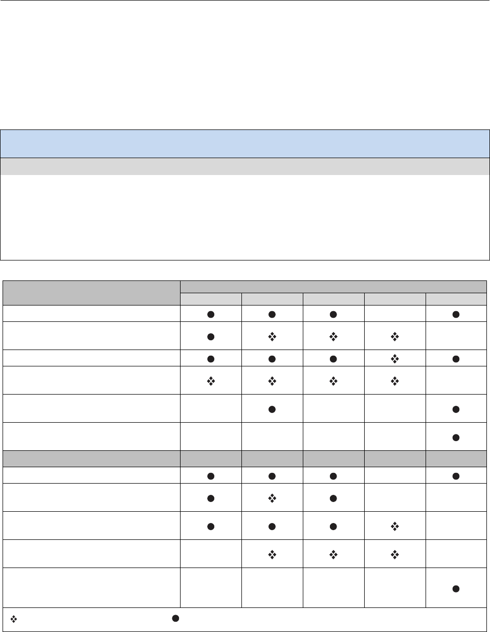
DVI DESIGN GUIDANCE DRIVER INPUTS
9-10
Control Coding
Introduction
Control coding is the set of design characteristics that serve to identify the control or to identify the relationship
between the control and the function to be controlled. This topic discusses the advantages and disadvantages of
different types of control coding.
Design Goal: Choose control coding that supports quick and accurate identification by drivers, reducing
eyes-off-road time.
Design Guidance
The best available research suggests using one or more of the following characteristics to identify controls:
• Location Coding: In order to ensure discriminable and unique control locations, controls may be separated by distances that
are sufficient to avoid confusion among positions.
• Shape Coding: This is most effective when used in combination with location coding. Errors in the driver’s hand position
are indicated by the feel of the control.
• Size Coding: This is most effective when used in combination with location coding. As many as two or three sizes can be
used to discriminate controls.
Advantages and disadvantages of various types of control coding [1].
Advantages
Type of coding
Location
Shape
Size
Texture
Labeling
Improves visual identification.
Improves non-visual identification
(tactual and kinesthetic).
Helps standardization.
Aids identification under low levels of
illumination and colored lighting.
When trans-
illuminated
May aid in identifying control position
(settings).
Require little (if any) training;
Is not subject to forgetting.
Disadvantages
May require extra space.
May adversely affect manipulation of
the control (ease of use).
Limited in number of available coding
categories.
May be less effective if operator wears
gloves.
Controls must be viewed (i.e., must be
within visual areas and adequately
illuminated).
Applies to Physical Controls only Applies to both Physical and Touch Screen Controls
Adapted from MIL-STD-1472G [1]

DRIVER INPUTS DVI DESIGN GUIDANCE
9-11
Discussion
The table on the previous page notes some advantages and disadvantages of various methods of control coding. The
symbols in the table refer to whether the advantage/disadvantage applies primarily to physical controls (e.g., knobs) or
both physical controls and touch screens. A defining difference between the two categories is that with touch screens,
the user is unable to rest their finger on the control without activation (if a tactile feedback membrane is not
incorporated [1]). This quality of touch screens restricts some of the coding applications, such as texture-coding or
non-visual control identification. Additionally, some touch screen technologies may not work if the user is wearing
gloves [1].
Several sources provide information about spacing and location of controls [2, 3, 4]. In particular, Campbell et al. [4]
provides a useful table that summarizes minimum control separation distances for various types of controls. In
addition, MIL-STD-1472G [1] recommends that controls that are associated with specific functions should be located
in standardized positions across control panels. Although this and other recommendations have been developed for
applications in environments other than automobiles, they provide helpful information regarding location coding and
avoidance of inadvertent activation of adjacent controls.
Lerner, Kotwal, Lyons, and Gardner-Bonneau [5] recommends that controls for different functions be shaped
differently to improve discriminability and to reduce glance times. Shape coding, often used on rotary knobs, may be
most effective at increasing identifiability of the control when used in combination with location coding. Shape coding
has an advantage in that it has a visual component in addition to a tactile component that can be used to identify the
control.
Size coding may not be as useful as shape coding. Size coding is most appropriate, however, in applications using
ganged controls. MIL-STD-1472G [1] recommends that no more than three different sizes should be used when
coding for absolute size. In addition, when used as coding parameters, knob diameters should differ by at least
1.27 cm (0.5 in) or knob thicknesses should differ by at least 10mm (0.4 in).
Three types of texture coding rarely are confused with one another: smooth, fluted, and knurled. However, different
methods and amounts of fluting or knurling may be confused with each other—but not with other types of texture
coding [3, 4].
Design Issues
When several controls are similar, they may be difficult to discriminate unless they are separated by an adequate
distance. Sanders and McCormick [3] cite a study in which blindfolded participants (which are similar to drivers
reaching for controls while keeping their eyes on the road) reached for horizontally and vertically arranged toggle
switches. For vertically arranged switches, only a small percentage of errors were made at distances of more than
6.3 cm (2.5 in) from the target switch. For horizontally arranged switches, approximately the same error rate was
found at distances greater than 10.2 cm (4 in). Therefore, horizontally arranged switches should be spaced farther
apart than vertically arranged switches. Controls may use combinations of coding to facilitate functional associations.
For example, rotary controls may be located in horizontal and vertical groups with each group using knobs of a
different size [2].
Wearing gloves reduces discriminability of texture-coded controls to varying degrees, depending on the type of
texture applied. Knurled knobs are the most difficult to discriminate when gloves are worn. Smooth knobs, however,
can still be discriminated from other texture types while wearing gloves [2].
Cross References
Labels for Controls, 9-12
Topic References
1. MIL-STD-1472G. (2012). Human engineering. Washington, DC: Department of Defense.
2. Boff, K. R., & Lincoln, J. E. (Eds.). (1988). Engineering data compendium: Human perception and performance. Wright-Patterson Air Force
Base, OH: Armstrong Aerospace Medical Research Laboratory.
3. Sanders, M. S., & McCormick, E. J. (1993). Human factors in engineering and design (7th ed.). New York: McGraw-Hill.
4. Campbell, J. L., Carney, C., & Kantowitz, B. H. (1998). Human factors design guidelines for advanced traveler information systems (ATIS)
and commercial vehicle operations (CVO) (Report No. FHWA-RD-98-057). Washington, DC: Federal Highway Administration.
5. Lerner, N. D., Kotwal, B. M., Lyons, R. D., & Gardner-Bonneau, D. J. (1996, January). Preliminary human factors guidelines for crash
avoidance warning devices (Report No. DOT HS 808 342). Washington, DC: National Highway Traffic Safety Administration. Available at
https://archive.org/download/preliminaryhuman00lern/preliminaryhuman00lern.pdf

DVI DESIGN GUIDANCE DRIVER INPUTS
9-12
Labels for Controls
Introduction
This topic provides recommendations for identifying controls and control settings using text or symbolic markings.
Design Goal: Identify controls with visible, recognizable, and unambiguous labels.
Design Guidance
The best available research on this topic suggests that this design goal can be met when:
• Controls are clearly labeled to identify their functions and settings.
• Labels are visible and recognizable before the driver reaches for the control, and are positioned so that the driver’s hand will
not cover the label when reaching for the control.
• International standards or recognized industry practices are used for the icons, legibility, words, acronyms, etc. labeling
controls and their settings [1, 2].
• Icons are used to represent values. In many cases, numerical values have little or no meaning for the driver.
• Controls that regulate a system function over a continuous range clearly identify the limits of that range (i.e., the min and
max of the system’s allowed settings are identifiable) [3].
Examples of labels for various types of controls.
Preferred
Not Preferred
Forward Collision Warning Sensitivity
OR
Side Collision Warning Sensor Range
Adapted from Pomerleau et al. [4], Campbell et al. [5], and General Motors Corporation [6]
ISO icons for warning systems.
Forward Collision
Warning System
Lane Departure
Warning System
Obstacle
Warning System
This excerpt is from ISO 2575:2010 [2], Icon Symbols K.15, K.16 and K.17 on page 46,
with the permission of ANSI on behalf of ISO. (c) ISO 2014 - All rights reserved.

DRIVER INPUTS DVI DESIGN GUIDANCE
9-13
Discussion
Labels are probably the most common method of identifying controls. However, they require visual inspection to
identify the control, whereas other coding methods do not. Nonetheless, labels should be considered the minimum
coding requirement for all controls. Properly chosen labels do not require much learning to comprehend [7]. Labels
that conform to internationally accepted standards or recognized human design principles will increase recognition
and comprehension of the control, particularly for drivers who use systems from different manufacturers and across
international markets. ISO standard 2575 [2] includes a few icons for warning systems. In applications for which no
standards exist, relevant design principles or empirical data should be used to determine the appropriate strategy for
control labeling [8].
Design Issues
One way to improve comprehension of control function and setting is to label the controls in a manner that is
consistent with population stereotypes for control-display relationships [3, 9]. For many control settings, such as
warning timing adjustments, numerical labels will have little meaning to the driver. Intuitive labels (e.g., “early” and
“late” or graduated icons) provide appropriate feedback to the driver related to the current setting of the control [4].
Labels for control settings may be textual or symbolic; however, symbols are preferred because they are not language-
specific, and they can be recognized more quickly than worded messages. In addition, symbols can be represented in
more spatially condensed forms, an important consideration in applications where the amount of available space is
limited [5, 9].
Text and symbols may be combined to improve comprehension of the control function and settings. For example,
Auto Alliance [8] included a variable-function switch for adjusting ACC headway gap and FCW warning sensitivity.
Buttons for increasing and decreasing the gap/sensitivity were labeled with up and down arrows, respectively. In
addition, these buttons included textual labels (“gap/warn”) to indicate the function of the control (see also Campbell
et al. [5]).
Since most controls will likely be positioned below the driver’s eye height, labels should be placed above the control
or in locations that will not be obscured by the hand when operating the control. In addition, labels should be located
in a way that allows them to be plainly visible to the driver before reaching for the control. Textual labels should be
oriented horizontally whenever possible. Vertical labels—if used—should be read from top to bottom [7].
Cross References
Selecting Character Height for Icons and Text, 6-8; Control Coding, 9-10
Topic References
1. MIL-STD-1472G (2012). Human engineering. Washington, DC: Department of Defense.
2. ISO 2575 (2010). Road vehicles—Symbols for controls, indicators and tell-tales. Geneva: International Organization for Standardization.
3. Federal Motor Vehicle Safety Standard (FMVSS) No. 101, Controls and displays, 36 FR 22902 (proposed Dec. 2, 1971) to be codified at 49 C.
F. R. pt.571.101. sec. 5.2.9. Available at www.gpo.gov/fdsys/browse/collectionCfr.action?collectionCode=CFR
4. Pomerleau, D., Jochem, T., Thorpe, C., Batavia, P., Pape, D., Hadden, J., ... & Everson, J. (1999). Run-off-road collision avoidance using IVHS
countermeasures (Final report. Report No. DOT HS 809 170). Washington, DC: National Highway Traffic Safety Administration. Available at
http://ntl.bts.gov/lib/jpodocs/repts_te/13342.pdf
5. Campbell, J. L., Richman, J. B., Carney, C., & Lee, J. D. (2004). In-vehicle display icons and other information elements, Volume I: Guidelines
(Report No. FHWA-RD-03-065). Washington, DC: Federal Highway Administration. Available at
www.fhwa.dot.gov/publications/research/safety/03065/index.cfm
6. General Motors Corporation. (2005). Automotive collision avoidance system field operational test (ACAS FOT) final program report (Report
No. DOT HS 809 886). Washington, DC: National Highway Traffic Safety Administration.
7. Sanders, M. S., & McCormick, E. J. (1993). Human factors in engineering and design (7th ed.). New York: McGraw-Hill.
8. Alliance of Automobile Manufacturers. (2006). Statement of principles, criteria and verification procedures on driver interactions with
advanced in-vehicle information and communication systems, including 2006 updated sections (Report of the Driver Focus-Telematics
Working Group]. Available at www.autoalliance.org/index.cfm?objectid=D6819130-B985-11E1-9E4C000C296BA163
9. Kiefer, R., LeBlanc, D., Palmer, M., Salinger, J., Deering, R., & Shulman, M. (1999). Development and validation of functional definitions and
evaluation procedures for collision warning/avoidance systems (Report No. DOT HT 808 964). Washington, DC: National Highway Traffic
Safety Administration.

DVI DESIGN GUIDANCE DRIVER INPUTS
9-14
Voice Recognition Inputs
Introduction
This topic addresses speech interactions between drivers and in-vehicle systems. It focuses on one-way speech input,
from the driver to the in-vehicle system. Although speech interactions may place cognitive demands on the driver,
unlike visual-manual interactions, they do not require drivers to take their eyes off of the road and their hands off the
steering wheel. Additionally, some simulator and on-road studies of speech interfaces reported better lane-keeping,
fewer glances away from the roadway, shorter glance durations, and lower subjective workload when compared with
visual-manual interfaces [1]. However, some research has indicated that voice recognition systems are associated with
increased off-road glances [2] and, therefore, it cannot be assumed, that using a speech input device does not have any
consequences for driver performance. Performing secondary tasks using speech input still uses cognitive resources
and, therefore, does not eliminate risk [3]. The precise effects of specific system parameters and implementations of
speech input on driver workload and driver performance are largely unknown.
Design Goal: Implement speech-controlled in-vehicle systems that have minimal input constraints, provide
user feedback, and have an error handling strategy.
Design Guidance
The best available research on this topic suggests that this design goal can be met when the user-input features accommodate the
following user requirements:
• Conversation Style:
−A natural conversation flow and cadence between the user and system is accommodated.
−Input vocabulary is minimized and is consistent with a terse interaction style.
• System Feedback:
−When starting an interaction, there is a notification that the system is ready for input.
−After the user provides input, there is feedback so the user knows their input was received.
• Error Handling:
−Speech input is only used when the consequences of recognition errors are low.
• General Design Goals [3] to consider:
−Reduce the user’s cognitive load to reduce the risk of performing secondary tasks while driving.
−Reduce interaction time.
−Increase task completion rate.
−Use feedback to the user that reinforces correct use.
−Design so that the users can form a mental model of the system behavior.
−
Design so that the system is both effective for an experienced user and appealing for a new user.
The accuracy of the speech recognizer, when considered with the number of steps required to complete a task, has a
large effect on the success rate of task completion. Shown in the table below is the probability of completing an
interaction using only as many steps as are required, given a fixed accuracy level for each step.
Number of steps required to complete an interaction
1
2
3
4
5
Accuracy level
of each step
0.99
0.99
0.98
0.97
0.96
0.95
0.95
0.95
0.90
0.86
0.81
0.77
0.90
0.90
0.81
0.73
0.66
0.59
0.80
0.80
0.64
0.51
0.41
0.33
0.70
0.70
0.49
0.34
0.24
0.17
0.60
0.60
0.36
0.22
0.13
0.08
0.50
0.50
0.25
0.13
0.06
0.03

DRIVER INPUTS DVI DESIGN GUIDANCE
9-15
Discussion
The available literature related to in-vehicle speech input is limited in empirical strength. Most of the design guidance
listed above was derived from studies with modest sample sizes, individual interface usability studies, the judgment of
experts in the field, or unpublished research results.
Conversation Style: Driver interactions with the system should be paced by the driver [4]. This leaves the driver free to
prioritize safe operation of the vehicle over responses to the in-vehicle system. When speaking, users should be able to
converse with the system using a normal conversational cadence. Drivers should not be required to exaggerate their
speech or insert artificial delays between words [5]. MIL-STD-1472G [5] states that “input vocabulary shall be
minimized, consistent with system needs, and selected to provide phonetically distinct elements to eliminate
misinterpretation.” Additionally, in a study of user preferences and responses to scenarios requiring speech input, 93
percent of commands issued were terse [6].
System Feedback: Lumsden [4] recommends that the interaction is initiated with a push-to-talk (PTT; press and release)
button followed by a listening tone. This teaches the user to wait for the tone to begin speaking, which is beneficial for
the recognition accuracy of the speech recognizer. Manual system input has clear proprioceptive, visual, and manual
feedback; however, the feedback provided after giving speech input is less apparent. The system should provide feedback
to the user so they know that their input has been received and understood [5]. Popp and Faerber [7] investigated
methods of providing feedback for non-transparent driver control actions (i.e., actions that have long delays before
reactions or barely noticeable reactions) performed using speech input. These actions relate to adjustments to collision
warning systems, which are also not immediately apparent. When providing feedback to nontransparent driver speech
input in a simulator, they found that an independent signal tone without visual feedback produced the least negative
effects. The visual display without signal tone also performed well.
Error Handling: MIL-STD-1472G [5] provides that speech recognition systems may be used when “the consequences of
recognition errors are low” and “identifying and correcting errors would be easy.” In a simulator study, rejection errors
(where the system did not respond to input) caused a smaller proportion of overall task errors (5%) and were more robust
against changes in system accuracy levels than substitution errors (where the system matches the user input to an
incorrect vocabulary word) [8]. Additionally, systems should require little user training [5].
General Design Goals: Lumsden [4] provides a list of general design goals for automotive speech interfaces. It should be
noted that although the guidance is consistent with that found in other sources, the list is made from the experience of the
authors and their unpublished research. Drivers may still have off-road glances while providing voice input. An
examination of a production-type (modified) automotive voice recognition system for text messaging found that voice
interactions increased non-driving related glances and increased driver mental workload as compared to baseline [2].
Design Issues
A simulator study of an in-vehicle speech system [9], found that the recognition accuracy of the system affected lane
position, when the accuracy level was very low (44%). PTT button use also affected driving performance when the
recognition rate was low. When testing recognition rates of 90 percent, 75 percent, and 60 percent in a simulator, Gellatly
[8] found that recognition rate did not affect driving performance except for the lowest rate (60%). When looking at
studies of recognition accuracy, it appears that the systems function well even with relatively low accuracy levels;
however, some negative effects on driving performance have been reported.
Topic References
1. Lo, V. E.-W., & Green, P. A. (2013). Development and evaluation of automotive speech interfaces: Useful information from the human factors
and related literature international. Journal of Vehicular Technology, 2013, Article ID 924170. Available at
www.hindawi.com/journals/ijvt/2013/924170/
2. Owens, J. M., McLaughlin, S. B., & Sudweeks, J. (2011). Driver performance while text messaging using handheld and in-vehicle systems.
Accident Analysis & Prevention, 43, 939-947. doi: doi:10.1016/j.aap.2010.11.019.
3. Strayer, D. L., Cooper, J. M., Turrill, J., Coleman, J., Medeiros-Ward, N., & Biondi, F. (2013). Measuring cognitive distraction in the
automobile. AAA Foundation for Traffic Safety. Available at: www.multivu.com/assets/60391/documents/60391-AAA-Measuring-Cognitive-
Distractions-Full-Report-AAA-Foundation-original.pdf
4. Lumsden, J. (2008). Handbook of research on user interface design and evaluation for mobile technology, Volume I. Available at
www.comm.rwth-aachen.de/files/lumsden122.pdf
5. MIL-STD-1472G (2012). Human engineering. Washington, DC: Department of Defense.
6. Aldridge, L. C., & Lansdown, T. C. (1999). Driver preferences for speech based interaction with in-vehicle systems. Proceedings of the Human
Factors and Ergonomics Society Annual Meeting, 977-981.
7. Popp, M. M., & Faerber, B. (1993). Feedback modality for nontransparent driver control actions: Why not visually? In A. G. Gale, I. D.,
Brown, C. M. Haslegrave, H. W. Kryusse, & S. P. Taylor (Eds.), Vision in Vehicles—IV (pp.263-270). Amsterdam: Elsevier Science.
8. Gellatly, A. W., & Dingus, T. A. (1998). Speech recognition and automotive applications: Using speech to perform in-vehicle tasks. Proceedings of the
Human Factors and Ergonomics Society Annual Meeting, 1247-1251.
9. Kun, A., Paek, T., Medenica, Z. (2007). The effect of speech interface accuracy on driving performance. Proceedings of the 8th Annual
Conference of the International Speech Communication Association (Interspeech 2007), 2332-2335.

DVI DESIGN GUIDANCE DRIVER INPUTS
9-16

SYSTEM INTEGRATION DVI DESIGN GUIDANCE
10-1
Chapter 10. System Integration
Driver distraction is increasingly identified as key contributing factor in many roadway crashes.
Concurrently, in-vehicle, crash avoidance, and wireless technologies continue to develop and
expand their presence within the vehicle. Thus, multiple systems are able to present information to
the driver and compete for the driver’s attention. These different sources of information may occur
simultaneously and during periods of increased driver workload.
System integration is the synthesis and incorporation of multiple sources of driver information into
the vehicle. It is vital to integrate and coordinate these sources of information so that drivers are
not presented with competing and potentially distracting messages while driving. The objective of
this chapter is to provide guidance about how to ensure the orderly presentation of information and
messages to drivers to maximize the chance that safety-relevant messages will reach the driver in a
way that maximizes safety benefits, while, at the same time, ensuring that non-safety-relevant
messages enrich the driving experience without distracting the driver in a way that undermines
safety.
Topics addressed in this chapter:
• Prioritizing Messages Presented to Drivers
• Using “Master” Warnings in Integrated Warning Systems
• Overview of the HFCV Integration Architecture

DVI DESIGN GUIDANCE SYSTEM INTEGRATION
10-2
Prioritizing Messages Presented to Drivers
Introduction
Message priority is specifically defined as the order of presentation of two or more in-vehicle messages [1]. More
broadly, it reflects the relative importance of messages or information items. This topic describes the SAE J2395
Recommended Practice for prioritizing messages and information presented to the driver [1]. For greater depth and
detail in using the procedures, see SAE J2395.
Design Goal: Use an integrated and systematic message prioritization scheme to ensure that drivers are
always presented with higher priority messages over lower priority messages.
Design Guidance
The following table reflects SAE J2395 [1] and may be used to determine message prioritization strategies:
Prioritized Driver Need
Action
1.Information requested by the driver Present immediately, if no other conflict
2.Continuous visual information Present continuously on a dedicated visual screen
3.Information about the external
environment or hazard
Apply safety/operational/time criteria from the Priority
Order Index (POI) from SAE J2395 [1]
The three criteria used to determine a message’s Priority Order Index (POI) [1].
Criteria
Definition
Examples
1) “Safety Relevance: The degree to which the information affects the safe operation of the vehicle.”
Directly Relevant
Direct safety information for decreasing risk of injury or
damage to driver, pedestrian, bicyclist, or vehicle.
• Imminent collision warning.
• Crash ahead warning.
Indirect/Somewhat
Relevant
Indirect safety information that might diminish error,
thus decreasing crash risk.
• Route guidance that indicates next
turn.
Not Relevant
Information that is not directly or indirectly related to
safety or decreasing crash risk.
• Convenience information, such as
email notifications, nearby shops or
restaurants, etc.
2) “Operational Relevance: The degree to which the information increases the ease and convenience of the driving
task, for example, by decreasing travel time and the stress associated with driving.”
Highly Relevant
Information related to inconvenience or expense for the
driver, such as vehicle damage.
• Notification of incident ahead
resulting in traffic delay.
• Engine temperature warning.
Moderately
Relevant
Information that provides some benefit to the driver
(increase ease or convenience), but incurs no cost if not
presented.
• Distance to the destination on a
navigation system.
• The price of a toll ahead.
Little or No
Relevance/Significa
nce
Information unrelated to ease or convenience.
• A mobile internet feature.
• The “stereo” indicator on an
entertainment system.
3) “Time Frame: Time sensitivity of the information The degree to which the information is time sensitive, that is, the
immediacy with which the information is required.”
Time Categories

SYSTEM INTEGRATION DVI DESIGN GUIDANCE
10-3
Discussion
Message prioritization is an important consideration as drivers are limited in their ability to attend to messages while
engaged in the primary driving task; overloading them with information can lead to driver distraction. Moreover, if a
message is warning drivers about an imminent hazard, all other less-important information should be filtered out so that
drivers have the best opportunity to receive and act on the critical message. At a very general level, the prioritization
approach described herein orders messages according to: (1) immediate crash and hazard information, (2) safety and
operational messages that are not urgent, but are time/location dependent, and (3) convenience information.
The SAE process [1] for determining the POI involves multiple steps, including:
1. Select a group of at least three prioritization evaluators that can objectively evaluate messages.
2. Describe individual messages in terms of their basic “information units”, which are the smallest useful piece
of information that can stand alone in both meaning and context.
3. Filter the messages using the flow diagram described in the design guidance.
4. Have the evaluators to determine the POI for each message using the criteria in the previous table. Results
should be discussed, and final POI ranks averaged across evaluators.
Note that SAE J2395 [1] frames the Safety Relevance criterion in terms of how direct the link is between the
information and potential hazards or increased crash risk. Crash-risk severity is not a consideration. This presents a
challenge for arbitrating the relative priority of high-priority imminent crash messages (e.g., forward crash warning
[FCW] versus blind spot warning [BSW]). ISO 16951 [2] guidance on message prioritization does take safety risk into
account, and may be helpful in this regard. Specifically, ISO 16951 [2] characterizes safety-related messages in terms
of criticality, such as the degree to which harm might result if the message is unheeded. There are four levels of
criticality, including: (1) severe or fatal injury, (2) injury or possible injury, (3) no injury but vehicle damage likely,
and (4) no injury and no vehicle damage. ISO does not separately identify Operational Relevance as a criterion,
instead incorporating this aspect into criticality.
Information items that are prioritized based on the POI should correspond in time with roadway, traffic, and
environmental events in a way that is consistent with how driver should use the information. For example, hazard
information should be presented immediately, whereas route guidance information should be presented far enough in
advance for drivers to comfortably prepare for the upcoming maneuver. Other information that is not time dependent
(i.e., discretionary) can be presented during information “down times,” when drivers have no other information
requiring their attention. An exception to this would be Discretionary messages that have a high Safety and
Operational relevance (e.g., flooded or closed roads ahead), in which drivers should receive the message with
sufficient time to change their route. Note that there is currently no information about how frequently drivers can be
presented with low priority messages before they get annoyed. It may be necessary to provide drivers with the
capability to control minimum presentation time for convenience messages, or disable them entirely.
Design Issues
There is no accepted protocol for integrating aftermarket or nomadic systems. Even if an aftermarket system connects
directly to an integrated system, POI provided by the aftermarket system may be unreliable or undefined and may not
contain the appropriate POI. Also, the ISO and SAE approaches may only provide a good starting point for
prioritization and may be less useful for difficult display conflicts (e.g., prioritization of different imminent crash
warnings [ICWs]).
Little research specifically addresses how to effectively disengage drivers from secondary tasks when higher POI
messages are presented. Holmes et al. [3] conducted an on-road study to measure the impacts of various ways to
interrupt tasks in a connected vehicle environment. The results showed that measures such as the time to complete the
task, the length and frequency of glances to the display, eyes on road time, and driver preferences for the method of
interruption were influenced by a host of variables, including driving context and environment, driver age, message
type (i.e., safety versus non-safety), and driver type (i.e., passenger vehicle versus heavy vehicle).
Cross References
Priority Order Index Look-up Table for Message Prioritization, 12-19; Tutorial 2: Priority Order Index Look-up
Table for Message Prioritization
Topic References
1. SAE J2395. (2002). ITS in-vehicle message priority. Warrendale, PA: SAE International.
2. International Organization for Standardization. (2004). Road vehicles - Ergonomic aspects of transport information and control systems (TICS)
- Procedures for determining priority of on-board messages presented to drivers (ISO/TS 16951). Geneva: Author.
3. Holmes, L., Doerzaph, Z., Klauer, S., & Smith, R. (2013). Volume 5 - Driver vehicle interface (DVI) interaction and task interruption final
research report (Unpublished Task 4 interim report prepared for NHTSA under contract DTNH22-12R-00629).
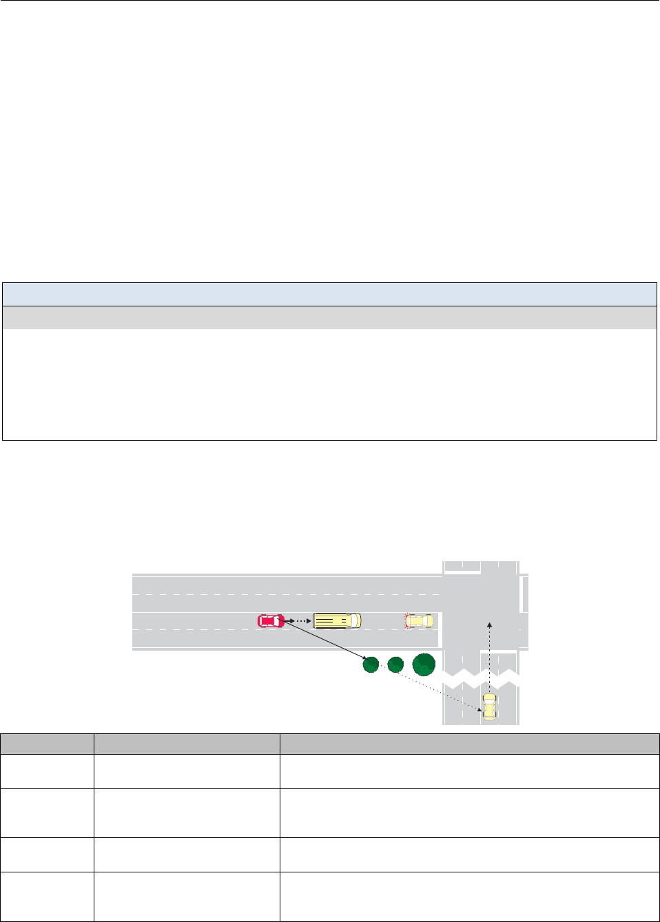
DVI DESIGN GUIDANCE SYSTEM INTEGRATION
10-4
Using “Master” Warnings in Integrated Warning Systems
Introduction
This topic provides information about the relative advantages and disadvantages of using master warning schemes (a
single alert for multiple safety applications) in comparison to separate and distinguishable messages for each safety
application. The use of “master” warnings leads to the possibility that drivers could be unclear or even confused about
the nature of the hazard associated with the warning, as well as about a proper response to the hazard. This reflects
three factors: (1) the physical similarity of warnings across applications, (2) the fact that these applications address
hazards in the same location relative to the driver, and (3) the possibility that some of the hazards may not be directly
perceivable by the driver. Overall, this could result in drivers making the wrong response, or unnecessarily delaying a
response because they required more time to determine the nature of the hazard. This issue is a concern regardless of
whether or not concurrent warnings are being presented to the driver (e.g., simultaneous FCW and BSW warnings),
although such a situation could compound the problem.
Design Goal: Design hazard warnings to support a timely and accurate response by drivers.
Design Guidance
The best available research on this topic suggests that, in situations where multiple integrated safety systems are
present and/or hazards may be difficult to perceive or detect, DVI effectiveness may be aided by :
• Securing and orienting driver attention to the immediate driving situation and any potential hazards.
• Placing a low memory-recall load on the driver.
• Providing sufficient distinctiveness across the warnings such that drivers can quickly identify the nature and location of the
hazard and decide on a response.
Master warnings could lead to driver confusion.
If a single, master alert is used in a vehicle equipped with multiple safety systems (such as a hypothetical connected
vehicle [CV] with forward crash warning [FCW], emergency electronic brake light (EEBL), BSW, do not pass
warning [DNPW], and intersection movement assist [IMA] safety systems), the driver could be confused about the
nature of the hazard as well as the proper response. The figure and table below describe how a single hazard warning
can potentially lead to confusion between two different system messages.
V
4
V1 V3
V2
Systems Scenario Shown in Figure Potential Driver Response Confusion
EEBL & FCW EEBL with variable space
between V2 and V3.
EEBL can require high or low level of deceleration depending on V2-V3
spacing, but likely requires hard braking with FCW.
IMA &
EEBL/FCW
IMA hazard for V1 when V1 is in
a platoon traversing an
intersection at speed.
Driver may misinterpret IMA as FCW or EEBL if they cannot see IMA
hazard, and miss opportunity to alter collision trajectory with V4.
DNPW & FCW V1 preparing to pass V2 while V2
decelerates unexpectedly.
Driver may misinterpret FCW as DNP and be delayed in braking for V2.
BSW & FCW V2 brakes while V1 driver doing
shoulder check (but no adjacent
vehicle present)
Driver may misinterpret FCW as BSW even though the adjacent lane is
clear. Driver would miss an opportunity to get out of the lane (or might
return to lane) of the FCW hazard.

SYSTEM INTEGRATION DVI DESIGN GUIDANCE
10-5
Discussion
From a design perspective, the competing design approaches and trade-offs associated with “specific versus master”
warning approaches are fairly straightforward. Single master alerts reduce the need for drivers to recall individual
“warning-hazard” pairings; they primarily serve to orient and direct drivers’ attention to the external scene, where they
can then identify the specific nature of the hazard and determine an appropriate response. Multiple alerts, specific to a
hazard, are coded cues that require drivers to successfully recall (or infer) the unique “warning-hazard” relationship
(although driving context and awareness of their situation may help), but may give drivers useful information that they
can use as they identify hazards and decide on a response.
The empirical research in this area is limited and far from consistent with respect to findings and design
recommendations. In particular, there is relatively little guidance in the literature regarding specific requirements for
distinctiveness of alerts in systems with large numbers of applications or for alerts with novel applications such as
EEBL. Brown et al. [1] provided design criteria that argued for maintaining distinctive warnings; these criteria were
derived from research indicating that distinct warnings are more effective than a system with a single, master warning
[2] and may lead to higher levels of driver acceptance [3]. The literature, though, is not conclusive, as some studies [4]
suggest that a single master alert may be sufficient to induce drivers to look up and assess the situation; however, the
situation may not be clear if the driving environment lacks visual cues that indicate the nature of the hazard. This
exact concern was evaluated by Thoma et al. [5] in a simulator study that examined driver comprehension and
response times to specific versus master alerts in situations where the hazard was easy to detect and in others where it
was difficult to detect. Though the study clearly has some limitations, performance in situations where the hazard was
difficult to detect was better with the specific warning.
A critical limitation in all of the research we have examined is the application-specific nature of the conclusions (a
limitation frankly expressed in Cummings et al. [4]). In short, the broad applicability of even the few studies relevant
to this issue is constrained by the number and nature of the specific applications under investigation. For example,
Chiang et al. [2] only looked at FCW and LCW systems, while Cummings et al. [4] only looked at FCWs and lane
departure warnings (LDWs). For more recent applications (e.g., EEBL, IMA, and DNPW), as well as unique
combinations of applications (e.g., FCW with DNPW and EEBL), there is insufficient evidence in the literature to say
conclusively whether or not distinctive warning presentations would improve drivers’ responses. Consequently, the
most appropriate approaches for determining which warnings should be distinctive between various applications and
where master alerts would suffice is unclear.
Design Issues
In general, the DVI design community may need to consider other options beyond the “single versus multiple” alert
paradigm and recognize that neither approach is likely to be optimal for all combinations of safety applications. Under
many very possible warning scenarios, single/master alerts are unlikely to carry enough information about the location
or nature of a hazard and could lead to driver confusion and errors, and (under these same circumstances) there can be
too many unique “warning-hazard” combinations possible for drivers to be able to recall them and act in a timely
fashion.
Cross References
Multimodal Warning Messages, 4-4; Warning Stages, 4-6
Topic References
1. Brown, J. L., Richard, C., Campbell, J. L., & Lichty, M. G. (2012). Human factors support for safety pilot. Task 2: Interface criteria for safety
pilot, model deployment (Final report). Washington, DC: Federal Highway Administration).
2. Chiang, D., Brooks, A., & Llaneras, E. (2004). Investigation of multiple collision alarm interference driving simulator study (Final task report.
Report for the Washington, DC: National Highway Safety Administration.
3. Ho, A. W. L., Cummings, M. L., Wang, E., Tijerina, L., & Kochhar, D. S. (2006). Integrating intelligent driver warning systems: Effects of
multiple alarms and distraction on driver performance. Proceedings of the 2006 Annual Meeting of the Transportation Research Board .
4. Cummings, M., Kilgore, R., Wang, E., Tijerina, L., & Kochhar, D. (2007). Effects of single versus multiple warnings on driver performance.
Human Factors, 49(6), 1097-1106.
5. Thoma, S., Lindberg, T., & Klinker, G. (2009). Evaluation of a generic warning for multiple intersection assistance systems. In D. de Waard, J.
Godthelp, F. L. Kooi, and K. A. Brookhuis (Eds.), Human Factors, Security and Safety (pp. 173-188). Maastricht, The Netherlands: Shaker
Publishing.

DVI DESIGN GUIDANCE SYSTEM INTEGRATION
10-6
Overview of the HFCV Integration Architecture
Introduction
This topic presents a HFCV Integration Architecture developed in support of research into vehicle-to-vehicle (V2V)
technology. This architecture governs delivery of information to the driver so that safety-relevant messages are
presented in a timely and effective manner. An integrated system, which thoughtfully controls the presentation of both
safety-relevant and non-safety-relevant messages to the driver, may increase safety by mitigating potential
consequences of increased information flow; such as overloading or inappropriately distracting the driver’s attention
from the primary task of driving [1]. As V2V research continues, this integration architecture may help support
managing the information that is presented to a driver during periods of increased workload. Tutorial 3 presents more
information on this topic.
Design Goal: Manage the presentation of information to the driver so that safety-relevant messages are
presented in a timely and effective manner.
Design Guidance
The Integration Architecture identifies three integration processing stages (see next page for details):
• Synthesize Inputs (synthesize contextual information)
• Manage Messages (arbitration through filtering, prioritizing, and scheduling)
• Present Information (cleared information is presented the driver)
Context diagram for V2V integration process.
Doerzaph et al. [1]

SYSTEM INTEGRATION DVI DESIGN GUIDANCE
10-7
Discussion
From Doerzaph et al. [1, see Tutorial 3 in this document], the figure on the previous page provides a context diagram
that illustrates the flow of information sources into the Dynamic Integrator (indicated by the multi-colored, multi-
ringed circle). The integration process ensures that messages are delivered to the driver with a controlled strategy, thus
reducing the likelihood that a safety-relevant message goes unnoticed by the driver or that it is perceived as less
critical, and increasing the likelihood that messages in general are provided in an appropriate manner (e.g., do not
overload the driver).
The figure outlines the basic problem space, indicating that successful integration may incorporate knowledge of:
• The vehicle state (e.g., speed, fuel levels, tire pressure, oil pressure, etc.).
• Roadway environment (including CV data originating from ambient traffic and roadside information sources (e.g., trajectories
and number of adjacent vehicles, proximate lane closures, traffic movement, work zone configuration).
• Driver state (e.g., alertness level) and interactive input (e.g., information requests, preference settings).
• Messages originating from applications that seek to present both solicited and unsolicited information to the driver.
Key steps in the integration process include:
Synthesize Inputs: In this step, details of context are determined through a synthesis of various driver, roadway
environment, and vehicle data. This data may be used by the integrator to make informed decisions during the
Manage Messages and Present Information processes detailed below. Generally, the data will be synthesized to
estimate the driver’s ability to safely perceive, recognize, and respond to the message. Such an estimate may be based
on a variety of measures, such as traffic density, speed, last interaction with the DVI, radius of roadway curvature and,
perhaps, direct driver monitoring systems when available. Additional inputs synthesized may include, but are not
limited to, the driver’s configured integration and application settings (discussed previously) and perhaps any
regulatory information that could influence when particular types of messages are permitted.
Manage Messages: The Manage Messages step is at the heart of the Dynamic Integrator and, during this task,
messages are arbitrated to determine which might be filtered (i.e., discarded), dynamically adjusted in relative priority,
and scheduled for presentation to the driver. Messages that are not appropriate given the current driving context may
be immediately filtered out. Filtering will occur based on user settings or when driving conditions indicate it is unsafe
to provide a given type of information content. When multiple messages are cleared by the filter, a prioritize process
will determine the relative importance of the messages and assign presentation order accordingly. Priority ordering
itself, however, does not determine when a message will be presented. Timing is the function of the scheduling
process which assesses the metadata and context information to determine when each message should be presented.
This process controls message cadence and ensures that drivers have the capacity to receive information while
focusing on the primary task of driving. In some cases, the schedule process may allow certain high-priority messages
to interrupt lower priority messages (e.g., in the case of an imminent safety warning).
Present Information: In this step, messages that have been cleared for delivery are analyzed and distributed to the
appropriate DVIs for information rendering. The Present Information process tracks the use of all DVIs and publishes
the information for the applications and Manage Messages processes to use. This status information contains details of
which applications are currently using the DVI and, when allowed by designers, which types of other applications
may share access. For example, consider a navigation application which is displaying map content across the large
center stack screen. The Present Information process may have provisions for allowing a small overlay to appear in
the screen corner which may, for example, display the current speed limit as populated from an in-vehicle sign
application.
Design Issues
This design guidance, as well as Tutorial 3, presents a proposed HFCV Integration Architecture model to be
considered by engineers, system developers, and designers in the development of future V2V systems. They are not
intended to represent the only approach to integration but, rather, to demonstrate an example approach that may be
leveraged by designers.
Cross References
Tutorial 3: Preliminary HFCV Integration Architecture, 12-21
Topic References
1. Doerzaph, Z., Sullivan, J., Bowman, D., & Angell, L. (2013). Connected vehicle integration research and design guidelines development:
Integration architecture, Task 5 (Report under Contract No. DTNH22-11-D-00236/0001). Washington, DC: National Highway Traffic Safety
Administration.

DVI DESIGN GUIDANCE SYSTEM INTEGRATION
10-8

APPLICATION TO HEAVY VEHICLES DVI DESIGN GUIDANCE
11-1
Chapter 11. Application of Human Factors Design Guidance to
Heavy Vehicle DVIs
This chapter provides information regarding special considerations that must be taken into account
when designing collision warning interfaces for use in heavy vehicles—specifically, heavy trucks
and transit buses. In general, the design guidance for passenger vehicles also applies to heavy
vehicles; however, the unique driving environments and driver tasks associated with driving heavy
vehicles require additional consideration when designing warnings for these vehicles. Vehicle
characteristics that must be considered for both heavy trucks and buses include vehicle size and
weight, braking distance, and limitations to visibility and maneuverability, while differences
between heavy trucks and buses include driver tasks and passenger considerations. Although the
available literature for warning designs in heavy vehicles is relatively sparse for most topics, this
chapter provides DVI design guidance that addresses these issues and considerations.
Topics addressed in this chapter:
• Design Considerations for Warning Signals in Heavy Vehicles
• Selection of Sensory Modality for Heavy Vehicle Warnings
• Design Guidance for Visual Displays in Heavy Vehicles
• Visual Display Location in Heavy Vehicles
• Design Guidance for Auditory Displays in Heavy Vehicles
• Design Guidance for Haptic Displays in Heavy Vehicles
• Driver Controls for Collision Warning Systems in Heavy Vehicles
• General DVI Considerations for Heavy Vehicles

DVI DESIGN GUIDANCE APPLICATION TO HEAVY VEHICLES
11-2
Design Considerations for Warning Signals in Heavy Vehicles
Introduction
This topic provides information regarding special considerations for designing collision warning system (CWS) signals for
use in heavy trucks and transit buses. CWS for these vehicles must consider the substantially larger size, heavier weight, and
different handling characteristics than passenger vehicles in their design. Also, they generally are noisier and vibrate more
than passenger vehicles, and the tasks required to drive these vehicles differ from those in passenger vehicles. These factors
must be considered when designing CWS in heavy vehicles.
Design Goal: Design warning signals that accommodate the size, weight, and driving conditions unique to
heavy trucks and buses.
Design Guidance
The literature suggests that these characteristics may be used in support of the design goal:
Warning Timing and Levels
• Heavy vehicles may require longer braking distances; advanced warning to facilitate longer headway or time-to-collision
may be needed as compared to passenger vehicles.
• Multi-stage warnings may help provide sufficient warning time to avoid hard braking and high deceleration.
Warning Signal Directionality
• Information about the direction of a hazard may aid drivers, especially in systems that integrate multiple detectors.
Warning Signal Intensity
• Visual warning signals are most detectible when they have an adequate range of intensities to be visible and salient under
varying ambient illumination and glare.
• Auditory signals are most detectible when they are sufficiently intense to overcome high levels of ambient noise and
adaptable to large fluctuations.
• Haptic signals are most detectible when they are sufficiently intense and/or have sufficient temporal characteristics to be
readily discriminated from ambient vibrations in the cab.
Examples of multi-stage visual forward collision warning (FCW) displays.
Adapted from Brown et al. [1]
Graded forward crash warning (FCW) warning from the Integrated Vehicle-based Safety System (IVBSS) field operational test
(FOT) provides fine-grained information regarding the diminishing headway. Yellow bars on the left of the display indicated
graduated levels of urgency for cautionary warnings (center three images) and a red bar across the top of the display indicated a
highly urgent, imminent warning condition (right). The visual alert was accompanied by an auditory signal that increased in
urgency as headway decreased.
From Stephens et al. [2]
Advisory
warning
front-left
Left Right
Left Right
Imminent
warning
front-left
Left Right
Cautionary
warning
front-left
Adapted from UCPATH & CMURI [3, 4]
This is a visual display that provides progressive warning levels.
Amber illumination is used for advisory and cautionary warnings,
and red illumination is used for imminent warnings. The number
of illuminated bars corresponds to the relative time-to-collision
(TTC), with more light emitting diodes (LEDs) illuminated as the
TTC becomes shorter [3,4].
Two-stage warning showing cautionary (left) and
imminent (right) collision warnings. The level of urgency
is indicated by the color of the icon and the proximity of
the lead vehicle to the truck. Amber is used to indicate
lower urgency (left), and red is used to indicate higher
urgency (right). The visual alert was accompanied by an
auditory signal that increased in urgency as headway
decreased (one cautionary and two imminent levels).

APPLICATION TO HEAVY VEHICLES DVI DESIGN GUIDANCE
11-3
Discussion
The potential differences in stopping distances between heavy vehicles and passenger vehicles require that heavy vehicles
travel with longer headways when following passenger vehicles in order to avoid rear-end collisions. Consequently, FCW
device thresholds must provide earlier warnings to heavy-vehicle drivers than those provided to drivers of passenger
vehicles. This requirement has led to recommendations that heavy truck crash warning systems (CWSs) should use
progressive (i.e., multi-stage or graded) warnings to provide drivers with sufficient warning time to avoid forward crashes
[5]. Similarly, a multi-stage collision warning is recommended in transit buses [6] in order to avoid hard braking and the
resulting abrupt deceleration to unrestrained passengers.
Information about the direction from which a hazard is coming is important, especially in systems that integrate multiple
detectors. Drivers of heavy vehicles will most likely benefit from having additional information regarding the location of a
detected hazard made readily apparent to them. Reinach and Everson [6] identified the requirement that transit bus collision
warnings indicate the direction of the hazard. In a transit bus implementation [3], an integrated CWS display used bars and
arrows to indicate the side of the bus from which the forward and side hazards were detected.
Design Issues
Highly variable ambient lighting, including the use of passenger lighting, was identified as a design issue for transit bus
CWS designs in Houser et al. [5]. Sun glare was also identified by transit bus drivers following their exposure to a prototype
CWS visual display [4]. These drivers indicated they had difficulty seeing the visual displays when driving directly into the
sun, a condition in which they felt having an FCW system would be highly beneficial. Because of the potential for reduced
visibility of visual displays, it is recommended that redundant signals of a second modality be used to increase drivers’
awareness of the situation.
Auditory signal strength must be sufficient to overcome ambient noise levels in a manner that does not startle the driver.
Noise levels in heavy vehicles vary, but are typically louder than those of passenger vehicles [7]. Design guidance in Lerner,
Kotwal, Lyons, and Gardner-Bonneau [8] identified the issue of potentially high noise levels in heavy trucks, noting that
such conditions could be addressed through the implementation of automatic, adaptive control of intensity. An overly loud
signal can induce an inappropriate (e.g., startle) response, potentially resulting in abrupt or hard braking by the transit bus
operator [5].
Haptic signals have traditionally been considered inappropriate for use in heavy-vehicle environments because they could
potentially be masked by ambient vibrations in the cab. Recent research [9], however, suggests that properly designed
vibrotactile signals in the seat pan can be detected in heavy-vehicle environments and that transit bus drivers prefer them
because the signals do not overload visual and auditory perceptual channels. Some drivers considered steering torque signals
to be inappropriate because they were uncomfortable with something else having control over the steering or because it
prompted them to steer at times when a steering response was inappropriate.
Cross References
Visual Warnings, Chapter 6; Auditory Warnings, Chapter 7; Haptic Warnings, Chapter 8
Topic References
1. Brown, J., McCallum, M., Campbell, J., & Richard, C. (2007). Integrated Vehicle-Based Safety System (IVBSS) heavy truck driver vehicle
interface (DVI) specifications (final version) (UMTRI-2008-27). Ann Arbor: University of Michigan Transportation Research Institute.
2. Stephens, D., Pape, D., LeBlanc, D., Bogard, S., Peredo, G., Berg, R., & Wells, B. (2014). Connected commercial vehicles—Integrated truck
project. Driver clinics, performance tests, and lessons learned. (Final report. Report No. FHWA-JPO-13-112). Washington, DC: Federal
Highway Administration. Available at http://ntl.bts.gov/lib/51000/51700/51726/13-112.pdf
3. University of California PATH & Carnegie Mellon University Robotics Institute. (2004). Integrated collision warning system final technical
report. Washington, D. C: Federal Transit Administration.
4. University of California PATH & Carnegie Mellon University Robotics Institute . (2006). Integrated collision warning system final evaluation
report. Washington, D. C: Federal Transit Administration.
5. Houser, A.; Pierowicz, J., & McClellan, R. (2005). Concept of operations and voluntary operational requirements for automated cruise
control/collision warning systems (ACC/CWS) on-board commercial motor vehicles. Washington, DC: Federal Motor Carrier Safety
Administration.
6. Reinach, S. J., & Everson, J. H. (2001a). Driver-vehicle interface requirements for a transit bus collision avoidance system (SAE Paper No.
2001-01-0052). Society of Automotive Engineers 2001 World Congress.
7. Fu, J. S., Calcagno, J. A., Davis, W. T., & Alvarez, A. (2010). Evaluation of noise level, whole-body vibration, and air quality inside cabs of
heavy-duty diesel vehicles. Transportation Research Record: Journal of the Transportation Research Board, 2194, 29-36. doi: 10.3141/2194-
04.
8. Lerner, N. D., Kotwal, B. M., Lyons, R. D., & Gardner-Bonneau, D. J. (1996, January). Preliminary human factors guidelines for crash
avoidance warning devices (Report No. DOT HS 808 342). Washington, DC: National Highway Traffic Safety Administration. Available at
https://archive.org/download/preliminaryhuman00lern/preliminaryhuman00lern.pdf
9. Pessaro, B., & Nostrand, C. V. (2011). Cedar Avenue driver assist system evaluation report (pp. 42). Washington, DC: National Bus Rapid
Transit Institute.

DVI DESIGN GUIDANCE APPLICATION TO HEAVY VEHICLES
11-4
Selection of Sensory Modality for Heavy Vehicle Warnings
Introduction
This topic provides information to support the selection of sensory modality (i.e., visual, auditory, or haptic) for
presenting messages in a heavy-vehicle environment. Factors that influence the choice of modality in heavy-vehicle
applications are largely the same as in passenger vehicles, with a few notable exceptions related to driver’s visual
scanning behaviors, long-term exposure to alerts, and passenger considerations. The information in this topic will help
designers determine which presentation modes are most appropriate for various messages.
Design Goal: Select DVI modalities consistent with heavy-vehicle driver tasks, needs, and expectations to
support a timely and accurate response by drivers.
Design Guidance
The best available research on this topic suggests that this design goal can be met when designers:
• Avoid using exclusively visual warnings for imminent collision warnings.
• Use an auditory or haptic signal in conjunction with a visual display to increase warning conspicuity. Auditory signals have
been shown to provide effective cautionary and imminent warnings, particularly as part of multimodal warnings.
• Use auditory or haptic signals as the primary mode of conveying collision warning information.
The use of haptic signals may be preferred over auditory signals in transit bus applications because they are less
obtrusive and less likely to be noticed by passengers. However, haptic signals have additional considerations to
ensure they are perceived. See Design Guidance for Haptic Displays in Heavy Vehicles (page 11-12) for issues,
caveats, and recommendations associated with using haptic signals in heavy vehicles.
The following table provides general recommendations regarding auditory, visual, haptic/tactile, and multimodal
display of CWS status information, cautionary warnings, and imminent warnings for heavy trucks and transit buses.
Warning types and suggested modalities.
Warning
Modality
CWS Warning Type
Status Information Cautionary Warning Imminent Warning
Auditory A neutral, generic tone can be
used to alert the driver to the
presence of status information.
An alerting tone or earcon can be
used to alert the driver to the
presence of more specific
cautionary information.
An attention-demanding tone
can be used to immediately
direct the driver’s attention to an
imminent hazard in heavy truck
applications.
Visual A readily interpreted written
message or icon can be used to
visually convey system status
information.
An appropriately located visual
signal can be used to convey the
relative level of the present
hazard and direct the driver’s
attention toward that hazard.
An appropriately located visual
signal can be used to convey the
imminent nature of the warning
and direct the driver’s attention
toward that hazard.
Haptic/Tactile Not recommended. Evaluation of adequate driver
comprehension, timely response,
and driver annoyance would be
required prior to implementation.
Evaluation of adequate driver
comprehension and timely
response would be required
prior to implementation.
Multimodal A multimodal auditory
annunciator coupled with a
visual icon or message is the
most commonly recommended
means of alerting and conveying
CWS status information.
A multimodal auditory alert
coupled with an immediately
recognizable visual icon or
indicator is the most commonly
recommended cautionary
warning.
An auditory alert coupled with
an immediately recognizable
visual icon or indicator is the
most commonly recommended
imminent warning for heavy
truck applications.

APPLICATION TO HEAVY VEHICLES DVI DESIGN GUIDANCE
11-5
Discussion
Because heavy-vehicle drivers perform continual visual scanning (e.g., the “keep your eyes moving” principle for
heavy-vehicle operation from the Smith System training program [1]), the amount of time drivers allocate their visual
attention to any given location is intentionally limited. Consequently, the time between glances to a visual warning
display imposes a potential delay in perceiving its visual warning, which means drivers may not always attend to an
exclusively visual imminent crash warning (ICW) with sufficient timeliness.
Existing evidence supports the use of bimodal information displays (e.g., simultaneous auditory and visual) to
enhance responses in heavy vehicles. In Belz, Robinson, and Casali [2], bimodal displays (e.g., auditory and visual)
for heavy truck FCW and lane change warning (LCW) resulted in faster brake response time and lower crash rates
(respectively) than a visual-alone or auditory-alone displays. DVI design requirements for transit buses [3] suggest that
multimodal warnings would be required in transit bus CWS due to the presence of a high amount of mechanical
vibration and ambient auditory noise, in combination with the high visual demands of the job. The use of bimodal
warnings could be problematic for specific systems under conditions associated with a high false alarm rate. An
integrated collision warning system for urban bus operations that was tested under controlled conditions by UC-PATH
and CUMRI only achieved a 65 percent and 35 percent correct warning rate for alert and imminent warnings,
respectively [4]. Bus operations can occur in dense urban areas, which require operators to operate close to vehicles and
pedestrians, resulting in the need for highly reliable warning thresholds as well as selection of the most appropriate
presentation modality.
Haptic signals have traditionally been considered inappropriate for use in heavy-vehicle environments because they
could potentially be masked by ambient vibrations in the cab; however, research is emerging that suggests haptic
signals may be useful in some applications. In a survey of Subject Matter Experts (SMEs) [5], SMEs indicated that
heavy truck designers have made improvements to cabs by way of reduced noise and vibration and that these
improvements may make haptic signals a viable option for collision warning systems. Recent research [6] supports the
use of haptic displays in transit buses, suggesting that properly designed vibrotactile signals in the seat pan can be
detected in heavy-vehicle environments and that transit bus drivers prefer them because the signals do not overload
visual and auditory perceptual channels. Advantages of haptic displays also include not attracting passenger attention,
providing a natural transition from warning to system control, and retainment of conspicuity under glare and high
ambient noise [7]. Some drivers untrained with the CWS, however, may mistake the brake pulse as a vehicle
malfunction [8]. Therefore, a brake-pulse display should be carefully evaluated before use.
Design Issues
The results from Belz et al. [2] should be taken with caution as their study conditions limit the generalizability of their
results. Driver workload was not measured or manipulated, which would have allowed for a more meaningful
comparison to actual truck driving, where workload may be quite substantial due to the complex nature of operating a
heavy vehicle.
Cross References
Multimodal Warning Messages, 4-4; Visual Display Location in Heavy Vehicles, 11-8; Design Guidance for Auditory
Displays in Heavy Vehicles, 11-10; Design Guidance for Haptic Displays in Heavy Vehicles, 11-12;Driver Controls for
Collision Warning Systems in Heavy Vehicles, 11-14; General DVI Considerations for Heavy Vehicles, 11-16
Topic References
1. Smith System Driver Improvement Institute, Inc. (2014.) The Smith 5 keys [Training Product]. Available at https://store.smith-
system.com/index.php/product/product/48/
2. Belz, S. M., Robinson, G. S., & Casali, J. G. (1999). A new class of auditory warning signals for complex systems: Auditory icons. Human
Factors, 41(4), 608-618.
3. Reinach, S., J, & Everson, J. (2001a). Driver-vehicle interface requirements for a transit bus collision avoidance system (SAE Paper No. 2001-
01-0052). Society of Automotive Engineers 2001 World Congress.
4. University of California PATH & Carnegie Mellon University Robotics Institute . (2006). Integrated collision warning system final evaluation
report. Washington, DC: Federal Transit Administration.
5. Brown, J. L., Reagle, G., Richard, C., Campbell, J. L., & Lichty, M. G. (2010). Commercial vehicle driver-vehicle interface needs specification.
Task 3 report: Conduct interviews. Seattle, WA: Battelle.
6. Pessaro, B., & Nostrand, C. V. (2011). Cedar Avenue driver assist system evaluation report (pp. 42). Washington, DC: National Bus Rapid
Transit Institute.
7. Reinach, S. J., & Everson, J. H. (2001b). The preliminary development of a driver-vehicle interface for a transit bus collision avoidance system.
Intelligent Transportation Society of America Eleventh Annual Meeting and Exposition.
8. Shutko, J. (2001). An investigation of collision avoidance warnings on brake response times of commercial motor vehicle drivers. (Unpublished
master’s thesis). Blacksburg, VA: Virginia Polytechnic Institute and State University.

DVI DESIGN GUIDANCE APPLICATION TO HEAVY VEHICLES
11-6
Design Guidance for Visual Displays in Heavy Vehicles
Introduction
Chapter 6 provided design guidance for visual displays; this topic provides an overview of additional factors that may
be considered for selecting and designing displays for heavy-vehicle applications. The design goals and design
guidance presented in Chapter 6 are generally applicable to the heavy-vehicle environment; the information below
provides some caveats and additional considerations. In general, the greater workload and visual complexity
associated with the heavy-vehicle driving environment suggests caution when adding new displays or when presenting
new information to the driver.
Design Goal: Select visual displays and visual display characteristics that accommodate heavy-vehicle
driver workload environment constraints.
Design Guidance
The literature suggests that these topics and considerations may support the design goal:
There are a number of issues and principles that are unique to heavy vehicles with regard to the location of visual
displays. General guidance for the location of a visual display is discussed on page 6-4. Considerations for heavy
truckes are discussed more comprehensively on page 11-8 (Visual Display Location in Heavy Vehicles).
There are no known or obvious revisions with respect to heavy vehicles for the use of the design goals or design
guidance presented in the following Chapter 6 topics:
• Visual Display Type for Safety-related Messages (page 6-2)
• Using Color (page 6-6)
• Selecting Character Height for Icons and Text (page 6-8)
• Temporal Characteristics of Visual Displays (page 6-12)
• Display Glare (page 6-14)
• Head-up Displays (page 6-16)

APPLICATION TO HEAVY VEHICLES DVI DESIGN GUIDANCE
11-7
Discussion
The heavy-vehicle (HV) cab visual environment presents special challenges to the HV driver who must continually
monitor the roadway and traffic while controlling the truck on the road. For example, the workload demands of HV
driving are typically viewed as higher than passenger vehicles, due to more complex vehicle control operations
(steering, shifting, and braking) and the need to adjust to potential hazards sooner because of longer braking times.
One advantage that HV drivers have in terms of the cab visual environment is that they sit higher than passenger car
drivers. As a result, they can see farther when there are vertical sight restrictions, such as hillcrests. This may permit
truck drivers to see traffic conditions or objects in the road sooner and, therefore, begin braking sooner.
One important aspect of the visual environment that is intended to be addressed by side-looking collision warning
systems is the visual blind spots that surround an HV. Because of the location of the driver and configuration of the
tractor and trailer, HV blind spots are not symmetrical on either side of the vehicle, with the driver’s right side having
more extensive unobservable areas. The extent to which visual blind spots can be attenuated through the use of fender-
mounted mirrors is an important consideration. In a study comparing early LCW systems, Mazzae and Garrott [1]
found that fender-mounted mirrors provided blind spot coverage superior to any other side object detection system
that they tested. Later work performed by Fitch et al. [2] examining a camera-based system providing side and rear
blind-spot views to heavy truck drivers indicated no significant increase or decrease in safety-critical event
involvement.
Imminent collision warnings for FCW and LDW are an important design issues in heavy vehicles. Design guidelines
for these systems [3] recommend that all such warnings that have priority for display should include a secondary
visual mode that supports rapid identification of the nature and location of the hazard and requires a minimal—or
no—glance time away from the imminent roadway hazard. An assessment of an ICW-only HV forward collision
warning system indicated that approximately half of drivers will look towards the instrument panel area during an
alert [4]. In general, the recommended visual display is a symbol/icon stimulus that is easily recognized as an FCW
indicator.
The use of HUDs in a heavy-vehicle environment has not been studied extensively. In general, head-up displays (HUDs)
have the potential to provide drivers with critical information while minimizing glance times away from the forward
roadway scene. While the design guidance on pages 6-16 and 6-17 can generally be applied to heavy vehicles, some
caution is warranted. In a transit bus application [5], 40 percent of drivers considered the HUD to be distracting,
commenting that the HUD increased workload and often did not provide sufficient benefit to warrant its use. Note that
this finding could have been related to the specific implementation of the HUD.
Design Issues
In general, designers of heavy-vehicle DVIs should be sensitive to the many unique driver, task, and environmental
considerations that might impact the development of safe and effective HV DVIs. Lichty et al. [6] conducted
interviews with designers of HV DVIs to determine their unique needs and wants for DVI information. Specific
heavy-vehicle characteristics that were believed to impact the design of visual displays include posture, greater
anthropometric range, low tolerance for false alarms, higher workload (including additional primary tasks such as
monitoring route, road restrictions, weigh stations, communications with dispatchers), and greater existing complexity
of the in-cab environment (e.g., up to 52 tell-tales already exist in most heavy vehicles).
Cross References
Chapter 6
Topic References
1. Mazzae, E., & Garrott, W. (1995). Human performance evaluation of heavy truck side object detection systems (SAE Technical Paper No.
951011). Warrendale, PA: Society of Automotive Engineers.
2. Fitch, G. M., Blanco, M., Camden, M. C., Olson, R. L., McClafferty, J., Morgan, J. F., ... & Hanowski, R. J. (2011). Field demonstration of
heavy vehicle camera/video imaging systems: Final report (Report No. DOT HS 811 475). Washington, DC: National Highway Traffic Safety
Administration.
3. Campbell, J. L., Richard, C. M., Brown, J. L., & McCallum, M. (2007). Crash warning system interfaces: Human factors insights and lessons
learned, final report (Report No. DOT HS 810 697). Washington, DC: National Highway Traffic Safety Administration.
4. Tidwell, S. A., Blanco, M., Trimble, T., Atwood, J., & Morgan, J. F. (in press). Evaluation of heavy vehicle crash warning interfaces.
Washington, DC: National Highway Traffic Safety Administration.
5. Pessaro, B., & Nostrand, C. V. (2011). Cedar Avenue driver assist system evaluation report (FTA Report No. 0010). Washington, DC: Federal
Transit Administration.
6. Lichty, M. G., Bacon, L. P., & Campbell, J. L. (2013). Connected vehicle DVI design research and distraction assessment. Activity 3: Human
factors design guidelines development. Task 13: Stakeholder and end-user feedback study (heavy vehicles) (Report to Virginia Tech
Transportation Institute). Seattle, WA: Battelle Center for Human Performance & Safety.

DVI DESIGN GUIDANCE APPLICATION TO HEAVY VEHICLES
11-8
Visual Display Location in Heavy Vehicles
Introduction
Visual warnings must be seen to be effective, and the location of a display plays an important role in its visibility. The
design guidance on page 6-4 for Locating a Visual Display is relevant because the locations that passenger and heavy-
vehicle drivers scan are similar, but there are a few differences. This topic addresses issues that are unique to heavy vehicles
with regard to the location of visual displays.
Design Goal: Place the primary visual interface in a location that facilitates rapid extraction of information
without obstructing the forward view or the view in the mirrors.
Design Guidance
The best available research on this topic suggests that this design goal can be met when:
• Display location is compatible with normal visual scanning behaviors that heavy-vehicle drivers are trained to perform.
• LCW/blind spot warning [BSW] primary displays are aligned with the driver’s line of sight to side-view mirrors.
• Visual collision warnings are not provided within the instrument panel of heavy vehicles.
• Visual displays are not placed in locations that can obstruct mirrors or the forward scene.
Heavy vehicle drivers typically allocate much of their visual resources to scanning the forward roadway and viewing their
mirrors to maintain awareness of lateral hazards. Visual warning displays for hazards in blind spots are best presented in
close proximity to the relevant mirror (e.g., near the left mirror for left BSW). The two upper frames in the figure below
depict typical blind spots for heavy trucks (adapted from FMCSA [1]) and transit buses (adapted from Thorpe et al. [2]). The
two lower frames of the figure depict results of on-road studies of heavy-vehicle driver glance times, providing drivers’
general allocation of visual resources in heavy trucks [3] and transit buses [4].
A. Depiction of heavy truck blind spots.
Adapted from FMCSA [1]
B. Depiction of transit bus blind spots.
Adapted from Thorpe et al. [2]
C. Heavy-truck driver allocation of visual resources.
Data from Tijerina et al. [3]
D. Transit bus driver allocation of visual resources.
Data from Göbel et al. (1998). Stress and strain of short haul bus
drivers: Psychophysiology as a design oriented method for analysis.
Ergonomics, 41(5), Taylor & Francis Ltd. [4]. Reprinted by permission
of the publisher.

APPLICATION TO HEAVY VEHICLES DVI DESIGN GUIDANCE
11-9
Discussion
Studies of overall visual allocation and individual glance times of heavy truck drivers [3] and transit bus drivers [4] indicate that
over 73 to 90 percent of glances during driving are directed outside of the vehicle (road scene, off road or outside). These sources
also indicate that heavy-vehicle drivers allocate approximately 10 percent of glance times to mirrors for glances that are typically
less than 1 second during driving. These findings suggest that FCW visual displays should be mounted in or near the forward
line of sight and LCW, BSW, and side collision warning (SCW) visual displays should be mounted in or near the side mirror line
of sight.
Driver glances to the instrument panel by heavy-vehicle drivers appear to be limited in both frequency and duration. The
available data suggest that heavy truck drivers allocate between 2 percent and 4 percent of their total visual glance time to
looking at the instrument panel [3]. Similarly, 3.2 percent of total glance time in transit buses [4] was estimated to be spent
looking at the bus instrument panel. These findings suggest that visual warning displays should not be located in instrument
panels; however, the instrument panel is an appropriate location for controls and status displays, especially if an auditory status
warning is provided to orient the driver to the display.
Although some sources have raised concerns regarding passenger disturbances from warnings [5, 6], these concerns have not
been found in revenue-generating operations with customers. The primary concern of warning presentation is safety. The best
guidance possible given the current state of knowledge is to present the safety information to the driver in accordance with
existing principles and, if possible, consider ways to minimize passenger disturbances.
Design Issues
Finding a suitable location to mount a visual display can be challenging in a heavy-vehicle cab where the available space for
mounting the display is limited. One strategy for locating a display in such a cab is to integrate the display into an existing
multifunction, central information, or hybrid/reconfigurable display used in the vehicle [7]. The high position of instrument
panels of some heavy trucks and motorcoaches may provide a position meeting display location criteria [8]. If this approach is
taken but the location does not meet the criteria for optimal visibility, the visual warning should not be the sole mode of
presentation. The visual display can provide redundant or supporting information to an auditory warning.
HUD visual elements need to be as simple as possible. An assessment of an integrated bus driver assist system that consisted of a
warning system that had a HUD with a high degree of visual complexity, in addition to redundant tactile warnings and warnings
from a tertiary visual display that showed a birds-eye view of the bus and surrounding obstacles is described in Pessaro and
Nostrand9. The visual complexity of the HUD resulted from the presentation of conformal images that overlaid all vehicles and
pedestrians located within range of the on-board sensors. In addition, the overlay images were color coded to provide multi-stage
warnings for pedestrians and vehicles. The assessment found 40 percent of drivers considered the HUD distracting, a source of
increased workload, and often not providing sufficient benefit to warrant its use [9]. If HUDs are used to provide warnings, the
images and content need to be visually simple (see Message Complexity, page 5-4).
Visual displays must not obstruct drivers’ visibility of the forward scene or of the mirrors. SMEs have expressed concern that an
improperly-positioned display in the A-pillar could obstruct the view of the mirrors and increase the size of blind spots [7].
Similarly, dash-mounted displays can obscure areas of the forward view if improperly placed. Display location must avoid the
occlusion of important visual information in the driving environment.
Cross References
Message Complexity, 5-4; Locating a Visual Display, 6-4
Topic References
1. Federal Motor Carrier Safety Administration. (n.d.). Share the road safely. Supporting materials campaign graphics (Webpage). Available at
www.sharetheroadsafely.org/SupportingMaterials/Graphics.asp
2. Thorpe, C., Duggins, D., McNeil, S., & Mertz C. (2002). Side collision warning system (SCWS) performance specifications for a transit bus.
Final report (prepared for the Federal Transit Administration, PennDOT Agreement No. 62N111, Project TA-34). Pittsburgh, PA: Carnegie
Mellon University Robotics Institute.
3. Tijerina, L., Kiger, S., Rockwell, T., Tomow, C., Kinateder, J., & Kokkotos, F. (1995). Heavy vehicle driver workload assessment. Task 6:
Baseline data study (Report No. DOT HS 808 467(6)). Washington DC: National Highway Traffic Safety Administration.
4. Göbel, M., Springer, J., & Scherff, J. (1998). Stress and strain of short haul bus drivers: Psychophysiology as a design oriented method for
analysis. Ergonomics, 41(5), 563-580.
5. Reinach, S. J., & Everson, J. H. (2001b). The preliminary development of a driver-vehicle interface for a transit bus collision avoidance system.
Intelligent Transportation Society of America Eleventh Annual Meeting and Exposition.
6. University of California PATH & Carnegie Mellon University Robotics Institute . (2006). Integrated collision warning system final evaluation
report. Washington, DC: Federal Transit Administration.
7. Brown, J. L., Reagle, G., Richard, C., Campbell, J. L., & Lichty, M. G. (2010). Commercial vehicle driver-vehicle interface needs specification.
Task 3 report: Conduct interviews. Seattle, WA: Battelle.
8. Tidwell, S. A., Blanco, M., Trimble, T., Atwood, J., & Morgan, J. F. (in press). Evaluation of heavy vehicle crash warning interfaces.
Washington, DC: National Highway Traffic Safety Administration.
9. Pessaro, B., & Nostrand, C. V. (2011). Cedar Avenue driver assist system evaluation report (FTA Report No. 0010). Washington, DC: Federal
Transit Administration.

DVI DESIGN GUIDANCE APPLICATION TO HEAVY VEHICLES
11-10
Design Guidance for Auditory Displays in Heavy Vehicles
Introduction
Chapter 7 provided design guidance for auditory displays; this topic provides an overview of additional factors that
should be considered for selecting the type of auditory display for heavy-vehicle applications. Certain auditory
displays may be more appropriate for certain commercial vehicle environments. Although the topics in Chapter 7 are
quite generalizable to the heavy-vehicle environment, and may be used for determining interface design features, this
topic discusses issues specific to heavy vehicles.
Design Goal: Select auditory display characteristics that accommodate the heavy-vehicle environment and
task constraints.
Design Guidance
The literature suggests that these topics and considerations may support the design goal:
When selecting and designing auditory displays in the heavy-vehicle environment that will present safety
information, there are no known or obvious revisions for the design goals or Design Guidance presented in the
following Chapter 7 topics.
• Distinctiveness of Warning Messages (page 7-10)
• Presenting Warnings Using Speech Messages (page 7-14)
• Perceived Urgency of Auditory Warnings (page 7-4)
• Perceived Annoyance of Auditory Warnings (page 7-6)
• Loudness of Auditory Warning Signals (page 7-8)
The Design Guidance statements on 7-2 and 7-12 require revisions for heavy trucking, as discussed below:
• Auditory Display Type (see also page 7-2)
− Avoid using auditory icons (e.g., tire skidding and loud horn honking) in transit buses.
− The use of automotive auditory signals (e.g., simple tones and earcons) is appropriate in heavy vehicles.
− At night, auditory displays may be preferable to visual displays in transit buses to prevent drivers from being
exposed to glare from the visual display.
• Using Localization Cues to Indicate Direction (see also page 7-12)
− Spatial auditory warnings may be difficult for drivers to localize in the noisy, acoustic reflective environment
of a heavy-vehicle cab. Localization cues, however, may increase the perceived urgency of auditory signals.
Some evidence suggests that localized sound may evoke a greater sense of urgency, even if drivers are not
able to identify the location of the warning signal due to noise and reflections in the cab [7].

APPLICATION TO HEAVY VEHICLES DVI DESIGN GUIDANCE
11-11
Discussion
Existing evidence supports the use of auditory signals for ICWs to ensure timely perception of warnings in heavy
vehicles. However, the nature of an auditory warning must take into account high levels of ambient noise with wide
fluctuations in intensity for all large vehicles [1], and warnings in transit buses should be salient enough to evoke
correct driver responses [2]. Also, because drivers spend a large proportion of their time in the cab, they are likely to
be exposed regularly to CWS sounds, and auditory alerts can be annoying. Consequently, the problems associated
with false and nuisance alarms, frequent alerts, and warning signal intensity are highly relevant issues in heavy-
vehicle environments. Heavy-truck drivers, however, will be likely to tolerate some level of annoyance with auditory
warnings if they see clear safety benefits from using the CWS [3].
Laboratory and limited test-track research have found auditory icons for forward collision warnings to elicit faster
brake responses than conventional, urgent-sounding, auditory warnings in heavy truck applications [4, 5]. Auditory
icons should be clearly distinctive from other sounds in the cab, with frequency and/or temporal characteristics that
are discriminable from other sounds, such as the engine [5]. Reinach and Everson [6] indicate that transit bus drivers
often tune out auditory alerts as a method of coping with the noise in the cab. Consequently, it is recommended that
auditory icons be used with caution or avoided altogether in transit bus applications.
In the heavy truck environment, the auditory cues that humans use to localize sound are likely to become blurred
because of acoustic reflections and noise in the cab, resulting in the potential for diminished ability to identify the
location of auditory signals. Nevertheless, recent research has shown that some localized sounds can have greater
effect on perceived urgency and situational awareness than comparable omnidirectional signals. In a heavy truck
simulator experiment, Larsson et al. [7] demonstrated that 3D auditory signals in a lateral (e.g., lane change) warning
were more activating and more negatively valent (i.e., more urgent) than when presented monophonically, even if
drivers couldn’t identify the direction of the sound. Similarly, in a test track study [5], sounds from the left and right
rear speakers elicited slower responses than sounds from the left and right front speakers.
Design Issues
The noisy environment inside heavy-vehicle cabs presents a real challenge to designing auditory displays. The
recommended sound levels for auditory warnings may be a problem because ambient noise levels can peak as high as
87 to 97 dBA [1] during discrete periods such accelerating and changing driving gears. The overall duration of
exposure in a heavy truck has been shown to be acceptable. For instance, time weighted average (TWA) sound levels
can be relatively lower than the Occupational Safety and Health Administration (OSHA) standard of 90dBA TWA for
heavy trucks (e.g., OHSA 8 hour TWA of 30 dBA [1]). Note that Hours of Service (HOS) regulations provide
property-carrying drivers with driving limits of 11 hours with a 14 hour limit in a duty period, and passenger-carrying
drivers with a driving limit of 10 hours with a 15 hour duty period [8].
Temporary muting of other auditory signals (e.g., the radio) during warning presentation can reduce the ambient
sound level in the cab. A study of a heavy truck forward collision warning system identified that muting competing
audio sources during presentation of an earcon-type auditory alert was not associated with faster brake response as
compared to other alerting strategies, yet was identified by participants as making the alert more salient [9].
Cross References
Chapter 7
Topic References
1. Fu, J. S., Calcagno, J. A., Davis, W. T., & Alvarez, A. (2010). Evaluation of noise level, whole-body vibration, and air quality inside cabs of
heavy-duty diesel vehicles. Transportation Research Record: Journal of the Transportation Research Board, 2194, 29-36. doi: 10.3141/2194-
04.
2. University of California PATH & Carnegie Mellon University Robotics Institute . (2004). Integrated collision warning system final technical
report. Washington, DC: Federal Transit Administration.
3. Battelle. (2004). Phase II driver survey report: Volvo intelligent vehicle initiative field operational test. Columbus, OH: Author.
4. Belz, S. M., Robinson, G. S., & Casali, J. G. (1999). A new class of auditory warning signals for complex systems: Auditory icons. Human
Factors, 41(4), 608-618.
5. Thompson, D. D., Wadding, K., & Garmon, E. (2013). Increasing truck driver's awareness: Use of in-vehicle 3D sounds. Available at the
Transportation Research Board website at http://onlinepubs.trb.org/Onlinepubs/IDEA/FinalReports/Safety/S19FinalReport.pdf.
6. Reinach, S. J., & Everson, J. H. (2001b). The preliminary development of a driver-vehicle interface for a transit bus collision avoidance system.
Intelligent Transportation Society of America Eleventh Annual Meeting and Exposition.
7. Larsson, P., Opperud, A., Fredriksson, K., Västfjäll, D. (2009). Emotional and behavioral response to auditory icons and earcons in driver-
vehicle interfaces. (Paper Number 09-0104). Proceedings of the 21st International Technical Conference on the Enhanced Safety of
Vehicles (ESV).
8. Federal Motor Carrier Safety Administration. (2013). Summary of HOS regulations as of July 1, 2013. Available at
www.fmcsa.dot.gov/documents/hos/HOS-RegulationsSummary-7-1-2013.pdf.
9. Tidwell, S. A., Blanco, M., Trimble, T., Atwood, J., & Morgan, J. F. (in press). Evaluation of heavy vehicle crash warning interfaces.
Washington, DC: National Highway Traffic Safety Administration.

DVI DESIGN GUIDANCE APPLICATION TO HEAVY VEHICLES
11-12
Design Guidance for Haptic Displays in Heavy Vehicles
Introduction
Chapter 8 provided design guidance for haptic displays; this topic provides an overview of additional factors that
should be considered for selecting the type of haptic display for a heavy-vehicle application. Certain haptic displays
may be more appropriate for certain commercial vehicle environments and in general haptic displays may be more
accepted by operators (e.g., bus drivers prefer haptic compared to auditory displays [1]). The topics included in
Chapter 8 are quite generalizable to the heavy-vehicle environment, and should be used for determining interface
design features, like vibration intensity, and where to position vibrating surfaces.
Design Goal: Select haptic display characteristics that accommodate heavy-vehicle environment and task
constraints.
Design Guidance
The best available research on this topic suggests that this design goal can be met when the following information is applied in the
heavy-vehicle cab:
• Selecting a haptic display for heavy vehicles (see also page 8-2).
− Use a haptic seat display, unless the use-case for a different display type is very strong: Commercial
driving collision avoidance systems have employed haptic seat, accelerator pedal and steering wheel
displays [1, 2] but the haptic seat displays are likely to be better received by most operators.
− Avoid using a brake pulse display until more research on human factors and information on mechanical
issues become available. Brake pulse displays will require additional research for commercial vehicles for
the following reasons:
The brake pressure required to cause the jerking sensation reported as beneficial for passenger vehicle
brake pulse displays may vary as a function of the load carried by the commercial vehicle, heavier
loads may require more brake pressure to create the jerking sensation.
The implementation of the brake pulse for a heavy truck will be dependent on the trailer type and
configuration, load weight, and load distribution.
It is highly likely that brake pulse displays are not appropriate for transit buses. Buses are driven as
smoothly as possible and ride smoothness is a quality of service factor that is recorded and used for
contract negotiations [3].
• General characteristics for haptic displays (see also page 8-4).
− Avoid active haptic interfaces: These interfaces may be too disruptive, distracting or confusing; research on
the human factors aspects of active haptic interfaces for commercial vehicles is limited.
− Avoid steering wheel torques: Bus drivers have reported a belief that steering wheel torques compromise
their control over the vehicle [1]. Although override forces (e.g., 3 ft-lbs; [4]) are low enough to mitigate
this concern, consideration may be needed prior to implementing a steering torque display.
− Use passive haptic interfaces (e.g., tactile vibrations in the seat): This type of interface offers an opportunity
to deliver information to bus drivers that passengers are not able to observe.
There are no known or obvious caveats for the remaining design goals or Design Guidance presented in Chapter 8:
• Improving distinctiveness of haptic displays (page 8-6)
• Accommodating for vibrotactile sensitivity across the body (page 8-8)
• Generating a detectable signal in a vibrotactile seat (page 8-10)
• Presenting spatial information using a vibrotactile seat (page 8-12)

APPLICATION TO HEAVY VEHICLES DVI DESIGN GUIDANCE
11-13
Discussion
Although the research on the use of haptic displays for heavy-vehicle applications is sparse, their use is still
recommended. ISO 17361 [5] and Houser et al. [6] state that an LDW system for heavy vehicles should issue a
warning via an audible or a tactile display when the warning threshold is exceeded.
There are only a few adjustments to the design information provided in the earlier topics within Chapter 8, and these
are simply to avoid the use of brake pulse displays and active haptic interfaces for commercial vehicle applications.
The advice against using brake pulses for commercial vehicles is supported by the logic that a high degree of brake
force will be required to create the jerking sensation but there is no research to support this claim. The jerking
sensation has been reported as the most effective aspect for passenger vehicle applications. For bus applications, the
jerking sensation may be problematic as customer satisfaction may be linked with the smoothness of the ride, which
would disqualify the general use of brake pulses―there is very little research on this topic as well. We could only find
one study to support the claim about the link between ride smoothness and customer satisfaction [3] and it is only
moderately helpful. It remains unclear how a brake-pulse display that exclusively activates in an emergency situation
impacts bus operations in general. If a break pulse results in drivers stopping buses before catastrophe (e.g., a collision
with a pedestrian) such a display may be found quite beneficial.
There are data on the effects of vehicle cab (i.e., whole body) vibrations on driver health and well-being from the
occupational health domain/literature, but information like this does not map directly to the design of information
systems that use localized vibration to deliver messages. The effects of long term exposure to vibration [7] are not
entirely relevant but may provide insight into what vibrational frequencies correspond with typical operations, which
is relevant for creating a vibrational signal that contrasts “natural” vibrations but is not adequately documented (see
also page 8-6). It is unlikely that the truck models are uniform enough in design for there to be a well-defined model
of the vibrations that actually reach the driver [8]. The hardware used to dampen vibration is too diverse to list in any
specific manner but—at a high level—tires, suspension, the driver-seat suspension (including active vibration- and
shock-mitigation technologies), and engine mounts all dampen vibration.
Design Issues
The design issues mentioned throughout Chapter 8 are applicable to heavy vehicles. In regard to training for passive
haptic displays, there is likely a better opportunity in the heavy-vehicle domain to provide drivers with such training
as there are already established means to provide training to new drivers [9] and experienced drivers [10].
Cross References
Chapter 8
Topic References
1. Pessaro, B., & Van Nostrand, C. V. (2011). Cedar Avenue driver assist system evaluation report (FTA Report No. 0010). Washington, DC:
Federal Transit Administration.
2. Gorjestani, A., Shankwitz, C., & Donath, M. (June, 2000). Impedance control for truck collision avoidance. Proceedings of the American
Control Conference. Chicago, IL.
3. Hensher, D. A. (2014). The relationship between bus contract costs, user perceived service quality and performance assessment. International
Journal of Sustainable Transportation, 8:5 (27), 5-27. doi: 10.1080/15568318.2012.758454 (Accepted author version posted online on January
22, 2013. Published online on June 24, 2013).
4. Ward, N. J., Gorjestani, A., Shankwitz, C., Donath, M., Boer, E., & DeWaard, D. (2003). Bus rapid transit lane assist technology systems.
Volume 2, Bus driver stress while operating in narrow dedicated bus shoulders: A pilot study (FTA-MN-26-7003). Washington, DC: Federal
Transit Administration.
5. ISO 17361. (2007). Intelligent transport systems—Lane departure warning systems—Performance requirements and test procedures. Geneva:
International Organization for Standardization.
6. Houser, A., Pierowicz, J., & McClellan, R. (2005). Concept of operations and voluntary operational requirements for automated cruise
control/collision warning systems (ACC/CWS) on-board commercial motor vehicles. Washington, DC: Federal Motor Carrier Safety
Administration.
7. Hassan, R., & McManus, K. (2002). Perception of low frequency vibrations by heavy vehicle drivers. Journal of low frequency noise, vibration
and active control, 21(2), 65-76.
8. Fu, J. S., Calcagno, J. A., Davis, W. T., & Alvarez, A. (2010). Evaluation of noise level, whole-body vibration, and air quality inside cabs of
heavy-duty diesel vehicles. Journal of the Transportation Research Board, 2194, 29-36. doi: 10.3141/2194-04.
9. Morgan, J. F., Tidwell, S., Medina, A., & Blanco, M. (2011). On the training and testing of entry-level commercial motor vehicle drivers.
Accident Analysis and Prevention, 43(4), 1400-1407.
10. Brock, J. F., McFann, J., Inderbitzen, R. E., & Bergoffen, G. (2007). Effectiveness of commercial motor vehicle driver training curricula and
delivery methods (CTBSSP Synthesis MC-13). Washington, DC: Transportation Research Board.

DVI DESIGN GUIDANCE APPLICATION TO HEAVY VEHICLES
11-14
Driver Controls for Collision Warning Systems in Heavy Vehicles
Introduction
This topic provides design guidance for implementing controls for CWS in heavy-vehicle applications. Specifically,
this topic identifies five CWS functions that might be placed under the driver’s control. These functions have been
identified primarily in passenger car CWS research and design guideline documents, as well as in a limited number of
documents that directly addressed heavy-vehicle CWS driver controls. It is readily evident that there is a significant
gap in available research upon which to base design guidance corresponding to this topic.
Design Goal: Provide adjustable CWS sensitivity and warning signal intensities to reduce the occurrence of
false and nuisance alarms, optimize signal intensity, and reduce driver annoyance.
Design Guidance
The best available research in both heavy- and passenger-vehicles, as well as established human factors concepts
when research findings are not available, suggest the following design guidance:
• Avoid allowing heavy-vehicle drivers to permanently disable the CWS.
• Provide controls to mitigate false and nuisance alarms:
− Provide heavy-vehicle drivers with the capability to temporarily reduce CWS sensitivity or mute auditory
warning signals in highly cluttered settings (e.g., construction zones) where high frequencies of false and
nuisance alarms would be encountered.
− Consider using intelligent sensing and algorithms or automated/adaptive techniques for identifying potential
false and nuisance alarms in order to minimize the need for drivers to make sensitivity adjustments.
• Provide heavy-vehicle drivers with control of CWS warning visual brightness and auditory volume. Limit adjustments to
ensure these signals meet the recommendations for minimum and maximum intensity.
• Consider providing adaptive level adjustment to automatically adjust brightness and/or auditory intensity.
Heavy Vehicle CWS functions: Recommended use and control types.
CWS Function Recommendation
Use Discrete
Control
Use Continuous
Control
On/Off
Enables and disables the CWS.
Note: Drivers should be notified of system
status for automatic system startup (i.e.,
ignition activated systems).
Not Recommended Yes Not Applicable
Sensitivity (Warning Timing, Warning
Threshold, Range, TTC)
Controls the physical or temporal proximity
threshold for which warnings are activated.
Neutral Recommendation
(i.e., can use if desired).
Limited Range of Settings
1
Yes
Between 2 and 6
Sensitivity Settings
Yes
Precise
Adjustment
Master Intensity
Master control for intensity of all displays
within a modality (i.e., visual, auditory, or
haptic). May include non-warning displays
(e.g., instrument panel (IP) brightness).
Recommended
Limited Range of Settings
2
Yes
Multi-position
Yes
Limited Range
Auditory Intensity
Controls the intensity of the auditory warning
signals.
Recommended
Limited Range of Settings
2
Yes
Multi-position
Yes
Limited Range
Visual Luminance
Controls the intensity of the visual warning
signals.
Recommended
Limited Range of Settings
2
Yes
Multi-position
Yes
Limited Range
1
Sensitivity adjustment should be limited to prevent drivers from adjusting the system to less than the minimum safe
headway or TTC.
2
Warning signal intensity adjustments should be limited to ensure these signals meet the recommendations for minimum
and maximum intensity. See Display Glare, 6-14; and Loudness of Auditory Signals, 7-8 for these recommendations.

APPLICATION TO HEAVY VEHICLES DVI DESIGN GUIDANCE
11-15
Discussion
Most passenger vehicle CWS currently on the market allow drivers to disable the system. Some current heavy truck CWS
designs incorporate an on/off control while other configurations do not allow drivers to disable the system. The
recommendation in the above design guidance is that a system on/off function not be provided because allowing the driver
to disable the CWS would nullify the fleet owner/operator’s intent in installing the system. Also, there is some limited
research that suggests most drivers would not choose to disable the system if given the opportunity. Specifically, 15 out of
18 drivers in Sayer et al. [1] indicated they preferred driving a truck with an integrated CWS installed, which suggests they
would use the technology if available.
System sensitivity settings are commonly implemented in CWS DVI designs. UC PATH and CMURI [2] suggested that
system sensitivity should be reduced during driving in a relatively cluttered environment, thereby reducing the frequency of
nuisance alarms. On the other hand, Wheeler et al. [3] noted that sensitivity controls may provide the benefit of increased
heavy-vehicle operator acceptance at the cost of delaying alerts until insufficient time is available to respond to an imminent
hazard.
In a heavy-vehicle FOT [4] that included a lane departure warning system, drivers frequently expressed annoyance with the
audible alarm of that system, which was considered to be set too loud and could not be adjusted by drivers. A heavy truck
ICW-only FCW presented at 87 dBA was rated as appropriate by approximately 81 percent of drivers, and not loud enough
by approximately 15 percent [5]. As is the case with system sensitivity settings, the necessary research has not been
conducted to support an evaluation of providing intensity controls on heavy vehicles; although, Houser et al. [6] provides an
optional design recommendation of providing an audible warning control with a minimum setting of 65 dBA.
Design Issues
In the absence of available research findings, the present design guidance recommends that heavy-vehicle system sensitivity
could be temporarily reduced by drivers to mitigate false or nuisance alarms. The suggested approach is to limit both the
duration and frequency of sensitivity reduction, basing the standard sensitivity setting on empirical analysis of driver
response times and vehicle stopping distances. In the IVBSS FOT [1], it was suggested that automated tracking could be
used to identify locations that produce repeated alerts with the aim of reducing warning sensitivity thresholds to minimize
false alerts.
A few references provided information that suggested the potential value of having minimum intensity levels that were
dependent upon ambient noise or luminance levels. Reinach and Everson [7] suggested using signal-to-noise difference to
create an adaptive minimum audible warning intensity that is at least louder than the ambient noise. Insufficient warning
visual luminance in high luminance conditions was identified by some of the transit bus drivers who participated in the pilot
test of the integrated CWS reported in UC PATH and CMURI [2], whereas the need for adequately low luminance for night
time transit bus operations has been identified by other investigators [7]. These extremes could be accommodated by a
system that provides ambient luminance sensing and adaptive display luminance adjustment that considers both minimum
and maximum display luminance ratios for high and low ambient illumination conditions.
Cross References
Driver Inputs, Ch. 9; False and Nuisance Warnings, 4-2; Loudness of Auditory Signals, 7-8; Display Glare, 6-14
Topic References
1. Sayer, J. R., Bogard, S. E., Funkhouser, D., LeBlanc, D. J., Bao, S., & Blankespoor, A. D., ... & Winkler, C. B. (2010). Integrated vehicle-
based safety systems heavy-truck field operational test key findings report (Report No. DOT HS 811 362). Washington, DC: National Highway
Traffic Safety Administration.
2. University of California PATH & Carnegie Mellon University Robotics Institute . (2006). Integrated collision warning system final evaluation
report. Washington, DC: Federal Transit Administration.
3. Wheeler, W., Campbell, J., & Kinghorn, R. (1998). Commercial vehicle-specific aspects of intelligent transportation systems. In W. Barfield &
T. A. Dingus (Eds.), Human Factors in Intelligent Transportation Systems. Mahwah, NJ: Lawrence Erlbaum.
4. Dinges, D., Maislin, G., Krueger, G., Brewster, R., & Carroll, R. (2005). Pilot test of fatigue management technologies (RN-FMCSA-RT-05-
002). Washington DC: Federal Motor Carrier Safety Administration.
5. Tidwell, S. A., Blanco, M., Trimble, T., Atwood, J., & Morgan, J. F. (in press). Evaluation of heavy vehicle crash warning interfaces .
Washington, DC: National Highway Traffic Safety Administration.
6. Houser, A., Pierowicz, J., & McClellan, R. (2005). Concept of operations and voluntary operational requirements for automated cruise
control/collision warning systems (ACC/CWS) on-board commercial motor vehicles. Washington, DC: Federal Motor Carrier Safety
Administration.
7. Reinach, S. J., & Everson, J. H. (2001b). The preliminary development of a driver-vehicle interface for a transit bus collision avoidance system.
Intelligent Transportation Society of America Eleventh Annual Meeting and Exposition.

DVI DESIGN GUIDANCE APPLICATION TO HEAVY VEHICLES
11-16
General DVI Considerations for Heavy Vehicles
Introduction
General DVI considerations are tied to situational factors and other operating demands heavy-vehicle drivers regularly
experience. While the design goals and design guidance presented in Chapter 3 are generally applicable to heavy
vehicles, the information below provides some additional considerations specific to heavy vehicles.
Design Goal: Design DVIs with careful consideration of the existing demands imposed by the heavy-vehicle
driving task so as to avoid disruption or interference with driving performance.
Design Guidance
The best available research suggests the following key features and design implications may affect this design goal:
Heavy Vehicle Drivers… Design Implications
…face greater workload under
normal driving conditions.
Due to vehicle size and loading, a manual transmission, significant mirror
use, and a greater need to be aware of their vehicle position in relation to
other vehicles, heavy-vehicle drivers typically encounter higher levels of
workload than light vehicle drivers [1].
…continually deal with
secondary task demands.
Because there are secondary tasks the driver is required to perform (e.g.,
route monitoring, road restrictions, using dispatching/routing systems) in
addition to the primary task of driving, heavy-vehicle drivers must
multitask while driving [1, 2].
…face a greater number of in-
cab messages that require
attention and memory.
More indicators on the dash, the result of a more complex cab environment,
create more messages that heavy-vehicle drivers must remember [1].
…benefit from effective
training.
Heavy vehicle drivers have more tasks they must learn how to perform and
information they need to deal with, and they benefit from enhanced
training. [3, 4]
When developing a safety system or application, research suggests minimizing the degree to which the application or
the information it provides adds to the complexity and workload of operating the heavy vehicle. Such added
complexity and workload could have negative consequences on driver performance. New systems and information
should be integrated into the cab environment with due consideration of workload and performance concerns. Use
non-invasive messages to provide non-safety related information, and take into account the driver’s ability to perceive
and respond to messages while driving. Chapter 10 provides additional information.
Common sources of workload and distraction in the heavy-vehicle cab environment.
Photograph: Comstock/Getty Images. Used with permission.

APPLICATION TO HEAVY VEHICLES DVI DESIGN GUIDANCE
11-17
Discussion
Distraction: The presence of certain driver systems in a heavy-vehicle cab may create a more distracting driving
environment than that of passenger vehicles. For instance, many heavy-vehicle drivers are required to interact with
dispatching devices that provide route, load, and other communications with the office; these systems have the
potential to have high levels of driver distraction [2]. When designing a DVI for use in a heavy-vehicle cab, the DVI
should not add to the complexity of the driving environment. This can be accomplished by minimizing the use of
attention getting methods such as a flashing icon in a non-urgent situation, locking-out certain functions of the DVI
while the vehicle is in motion, or by presenting information to the driver using a modality that does not compete with
those used for the driving task (e.g., auditory versus visual or verbal versus spatial) [5].
Workload: The workload that heavy-vehicle drivers encounter under normal driving conditions is greater than for
passenger vehicle drivers due to the nature of the driving task and due to the overall higher level of awareness
required regarding their own vehicle and surrounding vehicles. Heavy vehicle drivers are often trained using
structured systems (e.g., the Smith System [6]) which intend to help drivers anticipate, see, and react quickly to
driving challenges unique to heavy vehicles [3]. New DVIs or applications should not interfere with tasks or activities
that drivers are trained to complete via their training program.
Secondary Task Demands: While heavy-vehicle drivers have secondary tasks they must perform in addition to the
primary driving task, they must multitask to accomplish all of the required tasks. For example, drivers may have a
route and schedule they must stay on, are required to visit weigh stations as necessary, and the majority of drivers
have the same tasks of maintaining a trip log, tracking tolls they pay, and tracking the amount of time they spend in a
state, etc. [1]. To enable drivers to perform these tasks in addition to the primary driving task (only as necessary), the
tasks should be self-paced and use continuous displays so that drivers can access and use the information at a time of
their choosing.
In-cab Messages: Heavy vehicles have a number of systems or features that are not found in light vehicles (e.g.,
turnable axles, air systems, leveling systems, truck diagnostics displays) [1], resulting in more indicators on the dash.
This in turn creates more messages that heavy-vehicle drivers must remember. One way that this information can be
communicated to the driver is by using an icon, text or other visual display, which is covered in Visual Display Type
for Safety-related Messages (page 6-2). If another type of display is more appropriate, it should be presented in a
simple form, with a low number of information units, resulting in low memory demands on the driver. Information on
this topic can be found in Chapter 5 Message Characteristics.
Training: Heavy vehicle drivers benefit from effective training on the various tasks they are required to perform in
their vehicles because of the differences in operating a heavy vehicle compared to a light vehicle. When properly
trained, drivers are able to operate their vehicle more safely and are able to react to unexpected situations with more
ease than inexperienced drivers. It should be noted, however, that the amount of training and the type of training
received can vary greatly among heavy-vehicle drivers. A study by Morgan, Tidwell, Medina, and Blanco [4]
examined the effectiveness of three different types of training on commercial motor vehicle drivers’ skill levels and
found that longer, more structured training can offer distinct benefits that may increase operational safety on public
roads.
Topic References
1. Lichty, M. G., Bacon, L. P., & Campbell, J. L. (2013). Connected vehicle DVI design research and distraction assessment. Activity 3: Human
factors design guidelines development. Task 13: Stakeholder and end-user feedback study (heavy vehicles) (Report to Virginia Tech
Transportation Institute). Seattle, WA: Battelle Center for Human Performance & Safety.
2. Olson, R. L., Hanowski, R. J., Hickman, J. S., & Bocanegra, J. (2009). Driver distraction in commercial vehicle operations (Report No.
FMCSA-RRR-09-042). Washington, DC: Federal Motor Carrier Safety Administration.
3. Gupta, S., Olson, R., & Hanowski, R. (2009). Defensive driving tips for CMV drivers: An internet-based approach (Report No. FMCSA RRT-
09-003). Washington, DC: Federal Motor Carrier Safety Administration.
4. Morgan, J. F., Tidwell, S., Medina, A., & Blanco, M. (2011). On the training and testing of entry-level commercial motor vehicle drivers.
Accident Analysis and Prevention, 43(4), 1400-1407.
5. Regan, M. A., Young, K. L., Lee, J. D., & Gordon, C. P. (2009). Sources of driver distraction. In (Eds.) M. A. Regan, J. D. Lee, & K. L. Young
(Eds.) Driver distraction: Theory, effects, mitigation (pp. 249-279). Boca Raton, FL: CRC Press.
6. Smith System Driver Improvement Institute, Inc. (2014.) The Smith 5 keys [Training Product]. Available at https://store.smith-
system.com/index.php/product/product/48/

DVI DESIGN GUIDANCE APPLICATION TO HEAVY VEHICLES
11-18

TUTORIALS DVI DESIGN GUIDANCE
12-1
Chapter 12. Tutorials
This chapter contains informational tutorials. Tutorials are provided for important topics, special
issues, and detailed procedures that cannot be addressed within the two-page constraints of
individual design guidance topics.
Tutorials included in this chapter:
• Tutorial 1: Procedures for Assessing Driver Performance: Visual Demand Measurements
• Tutorial 2: Priority Order Index Look-Up Table for Message Prioritization
• Tutorial 3: Preliminary HFCV Integration Architecture
• Tutorial 4: Heavy Vehicle Characteristics and Driving Environment Relevant to DVI
Design

DVI DESIGN GUIDANCE TUTORIALS
12-2
Tutorial 1: Procedures for Assessing Driver Performance: Visual Demand Measurements
Introduction
Assessments of DVIs could include obtaining qualitative opinions about the system, examining
driver performance with the system, measuring the visual demands associated with the system (the
specific focus of this tutorial), and/or by assessing broader constructs such as workload or
distraction. Such assessments could occur at any point during design. Assessments of early
prototype interfaces could provide valuable insights for later design stages.
The goal of this tutorial is to provide an overview of methods and procedures for assessing visual
demand, and to list specific data sources that can provide more detailed information for interested
readers. The tutorial begins with discussion on a set of general heuristics for selecting assessment
methods. These heuristics are broadly applicable and are included early on to provide readers with
methods to evaluate the visual demand assessments discussed throughout the remainder of the
tutorial.
The majority of the tutorial consists of descriptions of methods and required minimum
instrumentation for carrying out assessments of visual demand. It also discusses selected study
examples that provide basic assistance relevant to using the assessment or research methods. For
the needs of this tutorial, visual demand should be considered as the proportion of time that a
driver’s eyes are directed toward a task, primary task of driving or secondary tasks. The amount of
time that a driver’s eyes are on the road scene has been used to empirically study attentional and
visual demands of driving (e.g., Senders et al., 1967; Tsimoni et al., 1999). For assessments of in-
vehicle system with interaction interfaces for the driver, visual demand has been assessed using
the amount of time that the driver or user looks at the interface (e.g., Horberry et al., 2008; Angell
et al., 2006).
The tutorial is designed to be read chronologically; it is organized as follows:
• Heuristics on Selecting a Driver Performance Assessment Procedure
• Descriptions of Selected Visual Assessment Techniques
Heuristics on Selecting a Driver Performance Assessment
While selecting a method for assessing driver performance, there are some heuristics that readers
should consider:
• A selected procedure should satisfy the “needs” of the assessment. In order for
practitioners to be able to select a procedure (or set of procedures), they need to determine if
it fulfills their assessment/research goals, as well as any schedule limitations and budget
constraints. Details about how driver performance studies have been carried out will help
when determining if a procedure is appropriate.
• Knowing the origins of a potential measure can be useful. Often it is the case that in order
to fully realize the implications of a procedure, it is necessary to have an understanding of its
rationale. As a result of the different ways in which seemingly-similar procedures are
actually carried out, it can be unclear as to what practitioners are attempting to measure or
accomplish. In some cases, it is necessary to review additional sources, including those that
describe the original purpose of a specific procedure.

TUTORIALS DVI DESIGN GUIDANCE
12-3
• Ensure the assessment procedure is a valid measure of the construct of interest. Some
tasks are more strongly associated with visual demand (e.g., radio tuning), others involve
primarily cognitive demand (e.g., mobile phone conversation), and some tasks can include
both visual and cognitive demand components (e.g., manual phone number dialing).
Understanding how these demands impact driving behavior (e.g., lane exceedances) is
critical; it is important to use appropriate methods to evaluate visual and cognitive load on
the driver and to be aware that there are many driving tasks that occupy both constructs of
demand (see Figure 12-1 below).
• Assess the components of the system that the driver will experience. It is important to
consider the purpose of assessments of driver performance within the larger context of
system design. Assessing the visual demands of an in-vehicle device includes examining
those aspects of the system that drivers actually experience (e.g., interface designs, activation
parameters, etc.) and—specifically—how well the driver interfaces support the functional
goals of the system, and the extent it does so in a way that maintains safe driving.
Figure 12-1. Visual and cognitive demands of common in-vehicle tasks
(Adapted from Engstroem & Maard, 2007).
• A key purpose for assessing the visual demand associated with a system is to
approximate how design features influence when and for how long drivers look at the
DVI and away from the road. Crash risk increases by three to four times that of normal
driving when drivers are visually distracted (Dingus et al., 2006; and Neale et al., 2005). Not
all glances away from the road carry the same degree of risk. Shorter glances away from the
forward roadway have been shown to have very little influence on crash risk, longer glances
(e.g., greater than 2 seconds for any purpose) increase crash risk by twice that of normal
driving (Klauer et al., 2006). A key determinant of visual distraction is where the driver is
looking and for how long. The safety effects of an in-vehicle device depend on an ability to
reliably determine the visual demand associated with the device—i.e. how the system affects
the duration and location of where drivers look. This tutorial contains a review of assessment
techniques that have been used to evaluate visual demand issues associated with driver
support systems. There are a limited number of techniques available to assess visual demand
issues associated with collision avoidance systems. Although there may be an opportunity to
adapt many of the evaluation practices and research procedures that are used to assess other
types of information systems (e.g., in-vehicle navigation systems), this option has yet to be
fully explored. Accordingly, assessment methods for collision avoidance systems will
certainly need to be further developed before standardized practices are possible.

DVI DESIGN GUIDANCE TUTORIALS
12-4
It is important to note that novel assessments techniques will be needed. It is highly likely that
there may not be an assessment procedure available for a specific research or assessment need.
Even the most mature collision avoidance systems (e.g., FCW and LCDAS) lack adequate
assessment techniques. Although there is considerable literature on these systems, there is also
considerable inconsistency in both the research and assessment procedures.
Descriptions of Selected Visual Demand Assessment Techniques
Table 12-1 below lists common assessment techniques, indicates which techniques have standards
or best practices documentation available, and which area of demand (visual, cognitive, or both)
they assess. There is an enormous amount of literature on the listed techniques, as well as many
other techniques that are used less often. There have also been multiple workshops on driver
metrics. Two of the four workshops occurred at Driving Assessment conferences. Proceedings
papers from the 4th workshop were published as a book that contains papers by many practitioners
in the field and is a recommended text for those interested in the research aspects of driving
metrics (Rupp (Ed.), 2010; see especially Angell (a, b), Benedict & Angell, Burns et al.,
Engstroem, McGehee et al., and Perez et al., which are included with other sources in an
Additional References section at the end of the tutorial).
Table 12-1. Common assessment techniques.
Common Assessment Techniques (tutorial topic)
Standardized
Type of Demand
Eye Glance Measures - Video Methods
Yes
Visual
Eye Glance Measures - Eye-Tracking Methods
No
Visual
Visual Occlusion Method
Yes
Visual & Cognitive
Occlusion Methods for Driver Assistance Systems
No
Visual & Cognitive
Peripheral Detection Task (PDT) *ǂ
In consideration
Visual & Cognitive
Lane Change Test (LCT) *
Yes
Visual & Cognitive
Sternberg Proxy Task **
No
Cognitive
* These are techniques for assessing cognitive demand, but because of the use of visual stimuli these techniques are often
conflated with visual demand; resolving the similarities between these techniques is a topic that is outside the scope of this
tutorial.
ǂ See Hsieh, Young and Seaman (2012) for details on the development of a PDT standard.
** The Sternberg Proxy Task is a widely-used assessment technique, so we have listed it here; however, it is not a visual
demand assessment technique and is, therefore, not described in this tutorial.
The following sections discuss how visual demand has been assessed using direct measures of
visual behavior (e.g., measurements of eye movements) and techniques that block-out vision for
short durations (e.g., visual occlusion methods). Eye glance measurements are discussed in the
context of standards and best practices (e.g., ISO and SAE standards and best practices
documents). Similarly, a later section on the visual occlusion method discusses standards and best
practices. Also discussed are alternative occlusion techniques that are not current standards and
best practices but have a long history of use for researching the effects of certain systems on driver
behavior. These alternative non-standard techniques may be more appropriate for assessments of
collision avoidance systems. The standard assessments are less suitable for most collision systems
due to their specific focus on completing longer duration tasks that are secondary to driving.
Direct Measurement of Eye Glance Behavior
Measuring eye glance behavior can provide information on where drivers look (e.g., toward the
roadway or toward in-vehicle devices). This section describes some basic aspects of eye glance
measures. Discussion on video-based and eye-tracker based methods follow.

TUTORIALS DVI DESIGN GUIDANCE
12-5
Quantifying where drivers are looking can help to identify how much visual demand is imposed
by in-vehicle systems and the driving environment. Driver’s visual search strategies can be
influenced by the visual demand of both the road scene and visual elements within their vehicle.
Informational needs of a driver contribute to visual search strategy (Hughes & Cole, 1988), but
informational needs change and depend on the intentions and expectations held by the driver; this
is in addition to the attention-capturing nature of the visual elements in the vehicle or in the
driving scene also influencing where drivers look (e.g., Cole & Hughes, 1984). Although drivers
tend to look toward what is relevant in the driving environment (e.g., toward the roadway or focus
of expansion), not all drivers exhibit the same glance behavior. Experienced drivers are better at
looking toward relevant elements of the driving environment than inexperienced drivers (Falkmer
& Gregerson 2005). There are also instances when drivers look away from the road for durations
that can undermine safe driving (e.g., when glances are longer than 2 seconds; Klauer, Dingus,
Neale, Sudweeks & Ramsey, 2006). Since eye glance behavior can be collected using video-
recording or eye-tracking systems, researchers and designers can obtain decent estimates about
how systems affect where drivers look.
General Information and Terminology
Some definitions are needed before moving on. For the remainder of this section, it will be
important to understand what is meant by target, fixation, saccades, glance, and transition as these
basic measures are highly relevant to additional measures discussed later. These basic measures
are defined in Table 12-2 below and can be obtained using video or eye-tracking methods, as
discussed in this tutorial.

DVI DESIGN GUIDANCE TUTORIALS
12-6
Table 12-2. Basic eye movement measures and definitions.
Basic Eye Movement Measures
Target Region A
(e.g., Interior mirror)
Time
Target Region B
(e.g., Roadway)
Target Region C
(e.g., DVI, Instrument panel,
Side mirrors, etc.)
Dwell
Tim e
Transition
Tim e
Glance Duration
Fixation
Transition
Saccade
This excerpt is adapted from ISO 15007-1:2014, Figure A.2 on page 10, with the permission of ANSI on behalf of ISO. (c) ISO 2014
- All rights reserved
• Target: A target is a predetermined area within the visual scene (e.g., road, mirrors, in-vehicle displays,
controls, IP devices, or combinations like Target Region C shown above). When video-based methods
are used there should be a minimum separation distance of at least 20° between targets. This will
facilitate differentiating between glances at different targets.
• Fixation: Fixation occurs when the eyes are aligned so that the fixated target or area of interest falls on
the fovea (central point of vision) for a given period of time (100ms to 20000ms; ISO 15007-1:2014).
• Saccade: The eye-movement that leads up to any fixation within a target region.
• Transition: The eye-movement from a fixation, glance location or one defined target location to
another target location (e.g., glancing from the road scene to an in-vehicle display; SAE J2396).
• Dwell Time: The total fixations and saccades within the target area between transitions (SAE J2396).
• Glance: The time from the moment at which the direction of gaze moves toward a target (e.g., an eye
movement toward the interior mirror) to the moment it moves away from target, i.e., this includes the
transition time to that target and dwell time (SAE J2396).
Glance is the most important metric as it is used to derive multiple other metrics.
The SAE recommended practice for measures of driver visual behavior, with respect to visual
targets that do not change their location over time (e.g., side mirrors) and for drivers that remain
reasonably still, provides definitions of various measures that can be obtained using video
methods (SAE J2396, 2000). Additionally, many of the measures can also be obtained using eye-
tracking methods since eye tracking methods are more general and can be used for visual targets
that change location over time and with drivers that vary their position. Assuming the above
conditions are met, one key factor for determining whether or not to use a video or eye-tracking
method is the granularity or size of the visual targets that are part of the evaluation. Video methods
can be used when the targets of interest are large and lead to eye movements that cover more
distance (e.g., the roadway as one target, another target being the interior mirror; Smith, Change,
Glassco, Foley, & Cohen, 2005), but video methods are less practical for looking at finer grain eye
movements between smaller areas of interest (e.g., areas of interest within the forward view;
Caird, Chisholm, & Lockhart, 2008); this is where eye-tracking methods become more necessary.

TUTORIALS DVI DESIGN GUIDANCE
12-7
Table 12-3 contains recommended measures, additional measures used in research, and measures
used in practice for evaluations of in-vehicle systems.
Table 12-3. Additional eye glance measures and definitions.
Additional Eye Glance Measures and Definitions
• Dwell Time: The sum of the duration of all glances/fixations and other eye movements (e.g.,
saccades) within a defined area that contains the visual target (SAE J2396).
• Glance Frequency: The number of glances to a target within a pre-defined sample time
period, or during a pre-defined task. Each glance must be separated by at least a single glance
to a different target (SAE J2396).
• Glance Probability: A ratio of the sum of all transitions to a specified location divided by
the sum of all transitions between all pairs of locations that occurred during the sample
interval. This measure reflects the proportion of transitions to the specific location of interest
(SAE J2396).
• Link Value Probability: The probability of a glance transition between two different
locations. For example, the link value probability between target locations A and B is defined
as the number of glance transitions from A to B plus the number of glance transitions from B
to A; this sum divided by the total number of glance transitions between all pairs of locations
in the sample interval is the link value probability (SAE J2396).
• Time Off Road Scene: The total time for glances away from the road scene (SAE J2396).
• Transition Time: The duration between the end of the fixation on a target location and the
start of the fixation on another target location (SAE J2396).
• Time-to-initial-transition: The amount of time between the onset of a visual element in the
driver’s field of view (e.g., a visual alert) and the last glance from an area of interest (e.g., a
display with a distraction task; Perez et al., 2009).
• Gaze Variability: Standard deviation in eye positions during a test interval. Vertical and
horizontal variability can be reported as separate measures (Caird et al., 2008).
This measure will require an eye tracker.
Glance data can be compared to other objective measures such as lane position variations, counts
of lane boundary crossings, lane departure duration, and speed variability. When reaction times
(e.g., accelerator-release reaction time, brake press time, button-press time) are included and
coupled with eye glance information, variables like forward glance decision time can be derived.
Forward glance decision time is the time between when a forward glance initiates and the desired
response occurs (Perez et al., 2009).
Table 12-4 shows a diagram of visual locations. The visual locations can serve as either individual
targets or multiple visual locations, both of which can be combined to create larger target regions.
The extent to which the visual locations are combined will depend on the technique that is used to
measure eye movements, video- or eye-tracker methods.
To a certain extent, eye-trackers can be used to obtain information at the level of the visual
location. Information about head rotational position will be necessary if practitioners are to use the
coordinate values from the eye tracker to compute a gaze vector or point of regard. There are
systems available to track eye and head movement (e.g., EYEHEAD
by ASL, faceLAB by Seeing
Machines). It will not be possible to compute the point of regard for other areas of interest without
head position information, unless the scene plane is known (e.g., as is the case with eye trackers
that are affixed to a display). The actual head movements that occur while driving make
computations of gaze appreciably more complex.

DVI DESIGN GUIDANCE TUTORIALS
12-8
Table 12-4. Diagram of visual examples.
Examples of Visual Targets
This excerpt is adapted from ISO 15007-1:2014, Figure A.1 on page 5, with the permission of ANSI on behalf of ISO. (c) ISO
2014 - All rights reserved
• Video methods are useful for coarser targets: e.g., the road scene as one target (A), another target
could be a combination of finer targets identified as a target area, for instance in-vehicle or off-road
(B, C and D, E and F, G and H).
• Eye-tracking methods are useful for finer targets: e.g., determining precisely where the driver is
looking within a DVI (C), the vehicle (B, C, D, G, E, etc. independently) or the road scene (areas of
interest within A).
Video Methods
Video methods can be used to obtain useful information about driver visual behavior. Video that is
captured during naturalistic studies can be examined to identify where drivers were looking during
pre-crash scenarios, which might provide insight on driver inattention (e.g., Klauer et al., 2006).
Many researchers have used video methods to observe driver visual behavior. Smith et al. (2005),
Angell et al. (2006) and SAE J2396 provide comprehensive reviews of methodological
considerations. Accordingly, these were the main resources used for the remainder of this section
about using video methods. Data capture and reduction techniques for video based eye movement
measures are summarized in Table 12-5.
The Crash Avoidance Metrics Partnership used software to code videos to expedite their data
reduction process. The software is called Observer 5.0 and is produced by Noldus Information
Technologies. It was used to code video, generate plots, and conduct inter-rater reliability. For
details on how this software was used to code video and complete additional analyses see Angell
et al., 2006.

TUTORIALS DVI DESIGN GUIDANCE
12-9
Table 12-5. Summary of data capture and reduction for video-based eye movement measures.
Video Method: Data Capture
Setting up:
How to position the
cameras
(SAE J2396)
• Ensure there is a clear view of the driver’s eyes by using proper positioning, aiming, and
exposure control of interior video cameras.
• Multiple cameras (2+) can be used and placed near the areas of interest and aimed
toward the driver to capture their eyes when they look toward the area of interest.
• Additional cameras can be used to identify when drivers are looking toward other areas
of interest.
Calibration
(SAE J2396)
• Calibrate the position of the cameras before data collection begins and at regular
intervals during tests (e.g., every 30 minutes).
• Calibrations are done to account for changes in driver posture that may affect how well
the cameras capture the driver’s gaze.
• The segments of the video recordings that contain the calibration can assist data coders
in deciding the characteristics of the driver’s visual behavior.
Video Method Data Reduction (Smith et al., 2005)
Steps for reducing video data:
1. Select and define areas of interest: e.g., on road and off road.
2. Select raters: A team of 2 raters with an optional third person to arbitrate disputes between the two raters.
Rating teams that are larger may be much less likely to reach consensus. A team of 5 raters was used to
reduce the video data to generate the plot below. Notes on which glances were disputed are shown.
3. Train raters: To ensure that all raters equally understand how to identify the defined areas of interest, train
them as a group rather than independently; if they all have the same understanding they will be better
equipped to resolve disputes.
4. Complete within-frames analysis: The first step is to have raters independently identify where the driver is
looking within each frame of video and mark the frame with the area of interest or target the driver was
looking at (e.g., on-road or off-road).
5. Collate within-frames analysis: Convert the video frame number to represent a time-stamp that can be used
to graphically represent visual behavior or be used to compute inferential statistics; this conversion also
allows for generating a correspondence with other data that are collected. Converging data in this manner
requires that the video be time synced with the other measures of interest (e.g., combine eye glance data with
acceleration data for multivariate analyses).
180 182 184 186 188 190 192 194 196 198
On Road
Off Road
Seconds
Full agreement for off-road glances
4 raters saw an off-road glance,
but 1 did not
1 rater saw an off-road
glance, but 4 did not
Full agreement
1 rater judged glance stayed
off road; others disagreed
2 raters saw an off-road
glance; 3 did not
1 rater started the off-road
glance later than the others
Recreated from Smith et al (2005). Methodology for capturing driver eye glance behavior during in-vehicle secondary tasks. Transportation
Research Board, No. 1937, Figure 1, p. 64. Copyright, National Academy of Sciences, Washington, D. C., 2005. Reproduced with permission
of the Transportation Research Board.

DVI DESIGN GUIDANCE TUTORIALS
12-10
Additional Considerations for Coding Glances From Eye Movement Videos
There are two additional data codes that have been used to categorize eye movements. CAMP used these data
codes in their Driver Workload Metrics (DWM) study to further quantify eye movements (Angell et al., 2006).
1. Task related glances: This code is used to identify glances that are linked with a non-driving task. The
simplest approach is to couple the start and end times of the task to the eye movements. Target regions can
also be associated with a task; e.g., CAMP labeled all glances down toward or near the IP and centerstack
as task related, but their process did require mediation from a 3rd
video coder as sometimes judgments of
where drivers were looking was not agreed upon by their main team of raters.
2. Glances used to track signs and roadway structures: Drivers may visually track signs or structures for a
segment of time leading up until the sign disappears from view, and this is considered a tracking eye
movement. Researchers may want to exclude these types of glances from analysis of specific areas of
interest.
Eye-Tracking Methods
There are several eye-tracking systems on the market. Eye trackers can be worn on the head (e.g.,
ASL’s The Mobile Eye), incorporated as part of a display or interface (e.g., Tobii X2 Eye
Trackers), or mounted on a vehicle dash (e.g., Seeing Machines faceLAB). All these systems use
cameras to capture images of infrared light reflected off of the cornea of the eye (i.e., Purkinje
images which are reflections of light off the boundaries of the lens and cornea of the eye). The
spatial relationship between these reflections and the location of the retina change in a relative
way depending on the rotation of the eye; this spatial relationship is used to calculate gaze
position, assuming the point of regard is known or included. The set-up, calibration and data
reduction process is quite different from using video methods. The data capture process is outlined
in Table 12-6 below.
Eye tracking equipment manufacturers typically offer data reduction software. These software
programs provide a wide variety of measures that are automatically processed. A few examples of
typical measures included in eye tracking software are: gaze paths, fixation heat maps, and dwell
time measures. Gaze paths and heat maps are often shown in combination with what the eye
tracking wearer was presented (e.g., heat map overlaying an image of a DVI).
Table 12-6. Summary of data capture and reduction using eye-tracking measures.
Eye-Tracking: Data Capture
Setting up:
First step is to position the
cameras and infrared light
source
• Eye-tracking systems usually consist of two types of cameras: a scene camera
and cameras for imaging the eyes.
• An infrared light must be incident toward the eye or eyes to create the required
reflections.
• Set-up typically requires ensuring that the cameras are aimed at the appropriate
areas of interest―with head-mounted eye-trackers; this may involve adjusting a
reflective monocle to ensure it is correctly lined up with the camera that is
capturing the image of the eye.

TUTORIALS DVI DESIGN GUIDANCE
12-11
Calibrating the eye-tracker
(Lange, 2013)
• Calibration is necessary to ensure that the system calculates the point of fixation
correctly.
• The calibration process typically requires that the observer focus their gaze at
known areas of interest. This can be accomplished using matrices of visible dots
that are shown across the field of view. (e.g., matrices of 4, 9, or 16 dots that are
spaced apart equally across the field of view).
• With many eye trackers, the eye-tracking data can be viewed in real-time as an
overlay with the video from the scene camera; this arrangement can be used to
verify calibration by requiring the observer to look at a predetermined location
while the researcher watches the video overlay.
• It is very important to assess for calibration shifts. This should at least be done
at the end of the data collection phase. If the calibration has shifted there are two
options:
− If the point of gaze still appears within adequate proximity to the area of
interest the data may still be valuable.
− If the shift is too great, the data may need to be discarded and replaced
using a different participant.
• Depending on the eye-tracking software, recalibration may be possible and
advised after a specific time interval (e.g., calibrate every 15 minutes) to reduce
data loss due to calibration shift.
Eye-Tracking Data Reduction
It is beyond the scope of this document to provide information on the computational aspects of reducing eye-
tracker data. Commercial eye-trackers are packaged with “canned” software that computes myriad measures of
visual behavior (e.g., those listed in this tutorial, heat-maps, scatter-plots, etc.). Some general recommended texts
that discuss methods to reduce eye-tracking data are:
• Duchowski, A. (2007). Eye-tracking methodology: Theory and practice (2nd Ed.). London: Springer–Verlag.
• Holmquist, K., et al. (2011). Eye-tracking: A comprehensive guide to methods and measures. Oxford: Oxford
University Press.
Methods of Visual Occlusion
ISO Visual Occlusion Method – The Standardized Proxy Task
The visual occlusion method can be used to assess visual demand associated with the use of visual
interfaces (ISO 16673, 2007). The standardized visual occlusion method is considered a proxy for
tasks that require drivers to balance their attention between driving and looking away from the
road to interact with an in-vehicle device. The results of tests that use the visual occlusion method
can be used to determine if an interface is appropriate for the task that it was designed to support.
This method can be used during early phases in the design life-cycle, as well as all the way
through to later phases. The major benefit to using the occlusion method is that it is simple and
can be accomplished with very little investment in specialized equipment. Tools like eye-trackers
and video cameras are not necessary. The major drawback is that the standard occlusion method
does not apply to assessments of most collision avoidance systems. The standard method is
discussed in the next table and limitations are included at the bottom of Table 12-7. Some basic
equipment is mentioned, dependent measures are discussed and an illustration of a test trial is
provided.

DVI DESIGN GUIDANCE TUTORIALS
12-12
Table 12-7. Summary of data capture and reduction using ISO’s visual occlusion method.
Visual Occlusion Method (ISO 16673)
Standard Methods The basic method requires that a participant complete a task using an in-vehicle interface.
The task should be completed while cycling between blocking and unblocking the
participant’s view of the in-vehicle interface. These vision and occlusion intervals should
be 1.5 seconds each. Cycles between vision and occlusion intervals should occur until the
task is completed and the participant verbally indicates that they are “Done!”
The amount of time or number of block/unblock intervals it takes for the person to
complete the task is recorded and compared to other measured parameters. Some
considerations for test methods are:
• Appropriate Test Environments: The test environment can be the vehicle cockpit if
the location of the interface is an important factor, or it can be a computer screen if
the interface location is not relevant or not yet relevant.
• Number of Participants: At least 10 participants should be used.
• Number of Test Trials: There should be at least 5 test trials per participant.
• Age: 20 percent of the participants should be over 50 years old. There will surely be
an effect attributed only to age. Practitioners should be prepared to look at the data
from older drivers independently from younger drivers (Horberry et al., 2008).
• Training: Two to 5 training trials may be necessary but the actual amount should be
based on how quickly the participant learns the task being tested and what is required
of them for the occlusion method.
Equipment
• The visual display itself could be blanked out as a possible technique for achieving
occlusion, or vision can be blocked completely by using occlusion goggles (e.g.,
Portable Liquid-Cyrstal Apparatus for Tachistoscopic Occlusion (PLATO) light
emittting diode (LED) lenses by Translucent Technologies Inc.).
• The purpose of occluding the display is to interrupt the visual portions of the task in a
controlled manner. ISO 16673 indicates that participants should be told that they are
allowed to operate the controls during the occlusion period. Practitioners allow
continued interaction even with displays that lack physical buttons (e.g., touch screen
interfaces) that tactually perturb the skin when touched (e.g., Horberry et al., 2008).
Standard Measures
• Total Task Time in Occluded Conditions (TTT
Occl
): This is the total task time for
completing the task for trials that contain occlusion intervals. This provides a measure
of task duration when the user is experiencing continual interruption.
• Total Task Time in Un-occluded Conditions (TTT
Unoccl
): This is the total task time
for completing the task for trials that do not contain occlusion intervals. This provides
a measure of task duration when the users are not interrupted.
• Total Shutter-open Time (TSOT): This is the total time that the subject can see the
interface while completing the task—i.e., the total time elapsed over only the visual
intervals of the trial.
• Resumability Ratio (R): This is a ratio of TSOT over TTT
Unoccl
. It provides an
indication of whether periodically shifting attention away from the in-vehicle
interface results in added time to complete the task. This additional time can be
considered as a cost, or an increased demand of performing the task while driving.
The value of R should be calculated on a within-participant basis. Logically, values
greater than 1 indicate there is an added cost to completing the in-vehicle task while
driving, but ISO gives no guidance on specific criterion values for R and they suggest
that users establish their own pass/fail criteria. Additional research is required before
establishing a standard target criterion value.
None of these measures indicate how well the task was performed.

TUTORIALS DVI DESIGN GUIDANCE
12-13
Diagram of a Test Trial under the Occlusion Condition
Vision Interval (
1.
5
s)
Total Task Time Occluded
(
TTT
Occl
)
Occlusion Interval
(1
.5
s
)
Timing Starts
Task Starts
Final Vision Interval
Task completes
Timing finishes
Task Continues
Alternates between
vision and occlusion
intervals
Limitations to the Standard Process
• The standard process is not appropriate for assessing tasks that are shorter than 5 seconds.
There are not enough shutter open and close intervals during short interval tasks (< 5 seconds) to provide
enough information about visual demand (ISO 16673). An alternative timing of 2 seconds for the closed
occlusion interval was used in the CAMP DWM project but in these studies the open interval was 1.5
seconds (Angell et al., 2006).
• Mis-estimations of resumability may result if the standard method is used without including a cognitive
task during the occlusion interval.
The occlusion interval does not at all impose additional cognitive demand on the participant, as does actual
driving. During actual driving the driver can be under various amounts of cognitive demand resulting from
glances toward the driving environment. Also, the standard occlusion method does not include a requirement
to impose cognitive demand during the occlusion interval. As a result, R may fail to account for additional
resumption costs associated with the extent cognitive load of driving also interrupts the task (Monk & Kidd,
2007).
• System delays can result in idle time that must be subtracted from task time measures.
Occlusion methods are not recommended for in-vehicle devices that exhibit system-response delays,
however, occlusion methods could provide estimates of effects on visual demand if the delay durations are
subtracted TTT and TSOT measures (ISO 16673).
• Benchmark value for excessive visual demand is not agreed upon and can be chosen by the user of ISO
16673.
The standards document for the occlusion method indicates that users develop the benchmark values and
criterion for excessive visual demand. The Alliance of Automotive Manufacturers (AutoAlliance) and the
Japan Automobile Manufacturers Association provide criteria and benchmarks (see Foley, 2008).
AutoAlliance states that TSOT for a task should not exceed 15 s, while JAMA states that it should be 7.5 s.
JAMA also suggests a vision interval of 1.5 s and an occlusion interval of 1.0 s.
Occlusion Methods for Driver Assistance Systems – Alternative Assessment Techniques
Researchers have used alternative techniques to assess driver support devices and many of these
techniques are similar to the standardized occlusion method only in that vision is blocked for
specific intervals during test scenarios. For all intents and purposes, the example methods
described in the subsequent table should be considered orthogonal to the standard occlusion
method. These alternative techniques have been used to evaluate driver support systems such as
heading control systems and collision warning systems. There are many insightful studies like
these that methodologically occlude vision in a way that is fundamentally inconsistent with the
ISO 16673 Standard Visual occlusion method. The standard occlusion test does not support
assessing the visual demand of all driving systems, which generates a necessity for these unique
methods, while also illustrating a need to develop a common or standardized method that can be
used for assessments of collision avoidance systems. This is not meant to dissuade anyone from
using the standard method, the standard occlusion method has been heavily scrutinized and, as a
result, the most basic aspects are now thought of as an insightful test of the level of visual demand
associated with an interface, but researchers and practitioners need to be aware of its limitations.

DVI DESIGN GUIDANCE TUTORIALS
12-14
This section discusses three visual occlusion techniques that are alternatives from the standard
method. The techniques are listed and discussed in the form of a structured literature review of
some relevant research (for additional examples see Van der Horst, 2004). Unlike the standard
visual occlusion method, these methods are more complex and the results are often more difficult
to interpret. The list below is sufficient to demonstrate that occluding a driver’s vision allows for
multiple approaches. The literature shown in Table 12-8 was chosen to demonstrate three different
occlusion methods.
Table 12-8. Literature review of three studies using occlusion methods of visual data capture.
Three Visual Occlusion Methods
1. Briefly occlude vision while the driver makes a maneuver that is relevant to the function of the system.
Schumann, J., Godthelp,
H., Farber, B., &
Wontorra, H. (1993).
Breaking up open-look
steering control actions—
The steering wheel as an
active control device. In A.
G. Gale et al. (Eds.), Vision
in Vehicles IV.
Amsterdam: Elsevier
Science.
• For this study, participants drove on a two-lane road and were required to merge into the
left lane. During the lane-merge their field of view became either completely obscured for
a fixed occlusion period (e.g., 2.4 seconds) or was left available and un-obscured. These
two conditions were repeated for several trials for each person. In many trials a barricade
appeared in the left-lane to indicate that the lane was closed, which prompted participants
to return to their driving lane. In other trials the barricade was in the right-lane, which
reinforced the purpose of the lane merger. For trials with a barricade in the left lane, an
alert was activated at a specific distance. There were 3 varieties of alerts based around
steering wheel rotational torque, the first one was weak and continuous, the second was
weak and discrete, and the third was strong and discrete.
• The results showed a large and significant effect supporting the use of the strong + discrete
warning type, but only when vision was occluded. When vision was not occluded there
was no substantial difference between the various alert styles. If this study had not included
the occlusion period then the assessment could have mistakenly concluded that all of the
alert types were equally effective, rather than demonstrating the superiority of the
strong/discrete warning.
2. Continuously occlude vision but make it available for short intervals at request of the driver.
De Vos, A. P., Godthelp,
J., & Kappler, W. D.
(1999). Subjective and
objective assessment of
manual, supported, and
automated vehicle control.
In: J. P. Pauwelussen,
(Ed.), Vehicle Performance
(pp. 97-120). Exton, PA:
Swets and Zeitlinger,
Lisse.
• For this study, drivers’ visual field of view was obscured while they were driving and only
when they pressed a switch were they able to see again for a short fixed duration (0.5
seconds). Occlusion in this sense was considered as the time during driving when the
driver does not need to look at the road.
• This occlusion technique was used to evaluate a Heading Control (HC) system that
assisted with lane keeping. The system provided a cue to indicate the required steering
wheel rotation. The results revealed that the HC system increased the average occlusion
time from 1.55 s (HC off) to 2.02 s (HC on), implying that HC allowed drivers to keep
their eyes off the road for slightly longer.
3. Occlude the forward scene to create a consistent eyes-off-road condition
Perez, M. A., Kiefer, R. J.,
Haskins, A., & Hankey, J.
M. (2009). Evaluation of
forward collision warning
system visual alert
candidates and SAE J2400.
SAE International Journal
for Passenger Cars -
Mechanical Systems, 2(1),
750-764.
• Performance was measured for responses to various icon configurations for forward
collision warning systems. Participants had to complete a discrimination task. First, a
forward scene was shown for a fixed interval (1.0 second) then was occluded for a variable
interval (e.g., 2.5, 3.0, 3.5, or 5.0 seconds). During the occlusion interval the visual
elements of the forward scene were either changed or left unchanged. After the occlusion
interval, the scene was revealed again and participants were required to indicate if any
element of the scene had changed.
• During the occlusion intervals participants were required to complete a visual based
secondary “eyes off road” task. Participants continued the secondary task until either the
occlusion interval ended or an in-vehicle visual alert was activated. They were instructed
that the scene would become visible 300 ms after the in-vehicle alert activated.
• There were multiple performance measures, some provided significant findings (e.g., eye
movement measures of the time it took for participants to look from the secondary task
display to the forward view). Some measures provided non-significant findings (e.g.,
accuracy and response time to the discrimination task did not result in significant
differences that depended on the design).

TUTORIALS DVI DESIGN GUIDANCE
12-15
The three occlusion methods mentioned above diverge from the standard occlusion method (ISO
16673) as a result of their focus on occluding driving relevant information rather than occluding
information relevant only to tasks secondary to driving. The purpose of the occlusion intervals in
the standard method is to serve as a proxy to driving. This distinction is important. The third
example above is the most similar to the standard occlusion method, as compared to the other two
examples. The concept behind it was to measure differences between interfaces for the same
system, and the task was to search for relevant information during the vision interval, either within
or outside of the vehicle. The testing condition was also much more complex. Drivers completed
multiple co-occurring activities. As a result, there was too much variability across participants and
test conditions to provide statistically meaningful results regarding testing interface options.
Although the standard method may not have been appropriate for such an assessment, it is much
more controlled which enhances its reliability and repeatability.
Upcoming Collision Avoidance Systems
In addition to the relatively mature systems, there are new safety systems (e.g., do not pass
warning [DNPW], emergency electronic brake light [EEBL], intersection movement assist [IMA],
and left turn across path [LTAP]) that are being developed and tested using connected vehicle
technology. The way that these new systems impact driving performance in general, but visual
demand in particular, is far from understood. For these novel systems, there is minimal research to
support standards or best practices for assessing compliance with human factors principles.
Tutorial References
Angell, L., Auflick, J., Austria, P. A., Kochhar, D., Tijerina, L., Biever, W., ... & Kiger, S. (2006). Driver workload
metrics. Task 2 final report (Report No. DOT HS 810 635). Washington, DC: National Highway Traffic Safety
Administration.
Caird, J. K., Chisholm, S. L., & Lockhart, J. (2008). Do in-vehicle advanced signs enhance older and younger drivers'
intersection performance? Driving simulation and eye movement results. International Journal of Human-
Computer Studies, 66(3), 132-144.
Cole, B. L., & Hughes, P. K. (1984). A field trial of attention and search conspicuity. Human Factors, 26, 299-313.
De Vos, A. P., Godthelp, J., & Kappler, W. D. (1999). Subjective and objective assessment of manual, supported, and
automated vehicle control. In: J. P. Pauwelussen (Ed.), Vehicle Performance (pp. 97-120). Exton, PA: Swets and
Zeitlinger, Lisse.
Dingus, T. A., Klauer, S. G., Neale, V. L., Petersen, A., Lee, S. E., & Sudweeks, J. D. (2006). The 100-car
naturalistic driving study, phase II—Results of the 100-car field experiment (Report No. DOT HS 810 593).
Washington, DC: National Highway Traffic Safety Administration.
Duchowski, A. (2007) Eye-tracking methodology: Theory and practice (2nd Ed.). London: Springer –Verlag.
Engstroem, J., & Maard, S. (2007). SafeTE final report (Report No. 2007:36). Vaegverket. Available at
http://trid.trb.org/view.aspx?id=862648
Falkmer, T., & Gregerson, N. P. (2005). A comparison of eye movement behavior of inexperienced and experienced
drivers in real traffic environments. Optometry and Vision Science, 82(8), 732-739.
Foley, J. P. (2008). Now you see it, now you don't: visual occlusion as a surrogate distraction measurement technique.
Iin M. A. Regan, J. D. Lee, & K. L. Young, et. al. (Eds.) Driver Distraction: Theory, Effects, and Mitigation. Boca
Raton, FL: CRC Press.
Holmquist, K., Nyström, M., Andersson, R., Dewhurst, R., Jaradzka, H., & van de Weijer, J. (2011). Eye-tracking: A
comprehensive guide to methods and measures. Oxford: Oxford University Press.
Horberry, T., Stevens, A., Cotter, S., Robbins, R., & Brunett, G. (2008). Development of an occlusion protocol with
design limits for assessing driver visual demand (Report No. PPR256). Available at the TRL website at
www.trl.co.uk/online_store/reports_publications/trl_reports/cat_intelligent_transport_systems/report_development
_of_an_occlusion_protocol_with_design_limits_for_assessing_driver_visual_demand.htm
Hsieh, L., Young, R., & Seaman, S. (2012) Development of the enhanced peripheral detection task: A surrogate test
for driver distraction. SAE International Journal of Passenger Cars—Electronic and Electrical Systems, 5(1):317-
325. doi:10.4271/2012-01-0965.

DVI DESIGN GUIDANCE TUTORIALS
12-16
Hughes, P. K., & Cole B. L. (1988). The effect of attentional demand on eye movement behavior when driving. In A.
G Gale, M. H. Freeman, C. M. Haslegrave (Eds.), Vision in Vehicles II (pp. 221-230). Amsterdam: North Holland.
ISO 16673 (2007). Road vehicles—Ergonomic aspects of transport information and control systems—Occlusion
method to assess visual demand due to the use of in-vehicle systems. Geneva: International Organization for
Standardization.
ISO 15007-1. (2014). Road vehicles—Measurement of driver visual behaviour with respect to transport information
and control systems—Part 1: Definitions and parameters. Geneva: International Organization for Standardization.
Klauer, S. G., Dingus, T. A., Neale, V. L., Sudweeks, J. D., & Ramsey, D. J. (2006). The impact of driver inattention
on near-crash/crash risk: An analysis using the 100-car naturalistic driving study data (Report No. DOT HS 810
594). Washington, DC: National Highway Traffic Safety Administration.
Lange, C. (2013). Evaluation of automotive HMI using eye-tracking—a revision of the EN ISO 15007-1 & IOS TS
15007-2. In N. A. Stanton (Ed.), Advances in Human Aspects of Road and Rail Transportation (Chapter 62). Boca
Raton, FL: CRC Press.
Monk, C. A., & Kidd, D. G. (2007). R we fooling ourselves: Does the occlusion technique shortchange R estimates?
Proceedings of the 4th International Driving Symposium on Human Factors in Driver Assessment, Training and
Vehicle Design, 2-8. Available at http://drivingassessment.uiowa.edu/node/2
Neale, V. L., Dingus, T. A., Klauer, S. G., Sudweeks, J. D., & Goodman, M. J. (2005). An overview of the 100-car
naturalistic study and findings. Proceedings of the 19th International Technical Conference on the Enhanced
Safety of Vehicles. Available at www-nrd.nhtsa.dot.gov/pdf/nrd-01/esv/esv19/05-0400-W.pdf
Perez, M. A., Kiefer, R. J., Haskins, A., & Hankey, J. M. (2009). Evaluation of forward collision warning system
visual alert candidates and SAE J2400. SAE International Journal of Passenger Cars—Mechanical Systems, 2(1),
750-764.
Rupp, G. L. (Ed.) (2010). Performance metrics for assessing driver distraction: The quest for improved road safety.
Warrendale, PA: SAE International.
SAE J2396 (2000). Definitions and experimental measures related to the specification of driver visual behavior using
video based techniques. Warrendale, PA: SAE International.
Schumann, J., Godthelp, H., Farber, B., & Wontorra, H. (1993). Breaking up open-look steering control actions—The
steering wheel as an active control device. In A. G. Gale et al. (Eds.), Vision in Vehicles IV. Amsterdam: Elsevier
Science.
Senders, J. W., Kristofferson, A. B., Levison, W. H., Dietrich, C. W., & Ward, J. L. (1967). The attentional demand of
automobile driving. Highway Research Record, 195, 15-33.
Smith, D. L., Chang, J., Glassco, R., Foley, J., & Cohen, D. (2005). Methodology for capturing driver eye glance
behavior during in-vehicle secondary tasks. Transportation Research Board, 1937, 61-65. Figure 1, p. 64.
Copyright, National Academy of Sciences, Washington, DC. Reproduced with permission of the Transportation
Research Board.
Tsimhoni, O., Yoo, H., & Green, P. (1999). Effects of visual demand and in-vehicle task complexity on driving and
task performance as assessed by visual occlusion (No. UMTRI-99-37, Ann Arbor: University of Michigan
Transportation Research Institute.
Van der Horst, A. R. A. (2004). Occlusion as a measure for visual workload: An overview of TNO occlusion research
in car driving. Applied Ergonomics, 35(3), 189-196.
Additional References
Alliance of Automobile Manufacturers. (2006). Statement of principles, criteria and verification procedures on driver
interactions with advanced in-vehicle information and communication systems, including 2006 updated sections
(Report of the Driver Focus-Telematics Working Group]. Available at
www.autoalliance.org/index.cfm?objectid=D6819130-B985-11E1-9E4C000C296BA163
Angell, L. S. (2010a). A comparison of the modified Sternberg method, peripheral detection tasks, and other surrogate
techniques. In G. L. Rupp (Ed.), Performance Metrics for Assessing Driver Distraction: The Quest for Improved
Road Safety. Warrendale, PA: SAE International.
Angell, L. S. (2010b). Conceptualizing effects of secondary task demands on event detection during driving:
Surrogate methods and issues. In G. L. Rupp (Ed.), Performance Metrics for Assessing Driver Distraction: The
Quest for Improved Road Safety. Warrendale, PA: SAE International.
Angell, L. S., McGehee, D. V., & Cooper, J. M. (2011). Test procedures for evaluating distraction potential in
connected vehicle systems: Task 5 performance metrics (Contract No. DTNH22-05-D01002 TO20). Washington,
DC: National Highway Traffic Safety Administration.

TUTORIALS DVI DESIGN GUIDANCE
12-17
Benedict, D. R., & Angell, L. S. (2010). Modified Sternberg method for assessing event detection while driving. In G.
L. Rupp (Ed.), Performance Metrics for Assessing Driver Distraction: The Quest for Improved Road Safety.
Warrendale, PA: SAE International.
Brook-Carter, N., Stevens, A., Reed, N., & Thompson, S. (2008). Practical issues in the application of occlusion to
measure visual demands imposed on drivers by in-vehicle tasks. Ergonomics, 52(2), 1-15.
Bruyas, M. P., Brusque, C., Tattegrain, H., Auriault, A., Aillerie, I., & Duraz, M. (2008). Consistency and sensitivity
of lane change test according to driving simulator characteristics. IET Intelligent Transport Systems, 2(4), 306-314.
Burns, P. C., Bengler, K., & Weir, D. H. (2010). Driver metrics, an overview of user needs and uses. In G. L. Rupp
(Ed.), Performance Metrics for Assessing Driver Distraction: The Quest for Improved Road Safety. Warrendale,
PA: SAE International.
Davis, G. A., Hourdos, J., Xiong, H., & Chatterjee, I. (2011). Outline for a causal model of traffic conflicts and
crashes. Accident Analysis and Prevention, 43(6), 1907-1919.
Engstroem, J. (2010). The tactile detection task as a method for assessing drivers’ cognitive load. In G. L. Rupp (Ed.),
Performance Metrics for Assessing Driver Distraction: The Quest for Improved Road Safety. Warrendale, PA:
SAE International.
Forkenbrock, G., Snyder, D., Heitz, M., Hoover, R. L., O'Harra, B., Vasko, S., & Smith, L. (2011). A test track
protocol for assessing forward collision warning driver-vehicle interface effectiveness (Report No. DOT HS 811
501). Washington, DC: National Highway Traffic Safety Administration.
Gelau, C., Jahn, G., Krems, J. F., Uno, H., Kircher, A., Ostlund, J., & Nilsson, L. (2003). State-of-the-art of the
SNRA/JARI/BAST joint research on driver workload measurement within the framework of IHRA-ITS.
Proceedings of the 18th International Technical Conference on the Enhanced Safety of Vehicles, Nagoya, Japan.
Harbluk, J. L., Burns, P. C., Lochner, M., & Trbovich, P. L. (2007). Using the lane-change test (LCT) to assess
distraction: Tests of visual-manual and speech-based operation of navigation system interfaces. Proceedings of the
4th International Driving Symposium on Human Factors in Driver Assessment, Training, and Vehicle Design, 16-
22.
Harbluk, J. L., Mitroi, J. S., & Burns, P. C. (2009). Three navigation systems with three tasks: Using the lane-change
test (LCT) to assess driver distraction demand. Proceedings of the 5th International Driving Symposium on Human
Factors in Driving Assessment, Training and Vehicle Design, 24-30.
Hoedemaeker, M., & Kopf, M. (2001). Visual sampling behaviour when driving with adaptive cruise control. Paper
presented at the Vision-in-Vehicles IX Conference, Brisbane, Australia.
Japan Automobile Manufacturers Association. (2004). JAMA guidelines for in-vehicle display systems—version 3.0.
Tokyo: Author.
LeBlanc, D. J., Bareket, Z., Ervin, R. D., & Fancher, P. (2002). Scenario-based analysis of forward crash warning
system performance in naturalistic driving. Proceedings of the 9th World Congress on Intelligent Transport
Systems.
LeBlanc, D., Sayer, J., Winkler, C., Ervin, R., Bogard, S., & Devonshire, S., ... & Gordon, T. (2006). Road departure
crash warning system field operational test. Volume 2: Appendices (UMTRI-2006-9-2). Ann Arbor: University of
Michigan Transportation Research Institute.
Liang, Y., & Lee, J. D. (2010). Combining cognitive and visual distraction: less than the sum of its parts. Accident
Analysis and Prevention, 42(3), 881-890.
McGehee, D. V., & Rakauskas, M. E. (2010). Driver performance metrics in interface design: Results of the 2nd
international driver metrics workshop. In G. L. Rupp (Ed.), Performance Metrics for Assessing Driver Distraction:
The Quest for Improved Road Safety. Warrendale, PA: SAE International.
McLaughlin, S. B., Hankey, J. M., & Dingus, T. A. (2008). A method for evaluating collision avoidance systems
using naturalistic driving data. Accident Analysis and Prevention, 40(1), 8-16.
Mehler, B., Reimer, B., & Wang, Y. (2011). A comparison of heart rate and heart rate variability indices in
distinguishing single-task driving and driving under secondary cognitive workload. Proceedings of the 6th
International Driving Symposium on Human Factors in Driver Assessment, Training, and Vehicle Design, 590-
597.
Mitsopoulos, E., Regan, M. A., Triggs, T. J., & Tierney, P. (2003). Evaluating multiple in-vehicle intelligent transport
systems: The measurement of driver acceptability, workload, and attitudes in the tac safecar on-road study.
Proceedings of the Road Safety Research, Policing, and Education Conference, 7(1), 176-184.
National Highway Traffic Safety Administration. (2011a). Crash warning interface metrics, phase 2 (Report No. DOT
HS 811 471). Washington, DC: Author.

DVI DESIGN GUIDANCE TUTORIALS
12-18
Ostlund, J., Peters, B., Thorslund, B., Engstroem, J., Markkula, G., Keinath, A., ... & Foehl, U. (2005). Adaptive
integration driver-vehicle interface (AIDE). Driving performance assessment—Methods and metrics (IST-1-
507674-IP). Available at www.aide-eu.org/pdf/sp2_deliv_new/aide_d2_2_5.pdf
Pauzie, A. (2008). A method to assess the driver mental workload: The driving activity load index (DALI). IET
Intelligent Transport Systems, 2(4), 315-322.
Pauzie, A., Manzano, J., & Dapzol, N. (2007). Driver's behavior and workload assessment for new in-vehicle
technologies design. Proceedings of the 4th International Driving Symposium on Human Factors in Driver
Assessment, Training, and Vehicle Design, 572-580.
Perez, M. A., Angell, L. S., & Hankey, J. M. (2010). Naturalistic driving: Crash and near-crash surrogate distraction
metrics. In G. L. Rupp (Ed.), Performance Metrics for Assessing Driver Distraction: The Quest for Improved Road
Safety. Warrendale, PA: SAE International.
Rupp, G. L. (Ed.) (2010). Performance metrics for assessing driver distraction: The quest for improved road safety.
Warrendale, PA: SAE International.
Santos, J., Merat, N., Mouta, S., Brookhuis, K., & de Waard, D. (2005). The interaction between driving and in-
vehicle information systems: Comparison of results from laboratory, simulator, and real-world studies.
Transportation Research Part F: Traffic Psychology and Behaviour, 8(2), 135-146.
Sayer, J. R., Bogard, S. E., Funkhouser, D., LeBlanc, D. J., Bao, S., & Blankespoor, A. D., ... & Winkler, C. B.
(2010). Integrated vehicle-based safety systems heavy-truck field operational test key findings report (Report No.
DOT HS 811 362). Washington, DC: National Highway Traffic Safety Administration. Available at
http://www.umtri.umich.edu/public/ivbss/IVBSS_Heavy_Truck_Key_Findings_Report_-_DOT_HS_811_362
Sayer, J. R., Funkhouser, D. S., Bao, S., Bogard, S. E., LeBlanc, D. J., & Blankespoor, A. D., ... & Winkler, C. B.
(2010). Integrated vehicle-based safety systems heavy-truck field operational test methodology and results report
(UMTRI-2010-27). Ann Arbor: University of Michigan Transportation Research Institute.
Sayer, J. R., Mefford, M. L., Shirkey, K., & Lantz, J. (2005). Driver distraction: A naturalistic observation of
secondary behaviors with the use of driver assistance systems. Proceedings of the 3rd International Driving
Symposium on Human Factors in Driver Assessment, Training, and Vehicle Design, 262-268.
SAE J2364 (2004). Navigation and route guidance function accessibility while driving. Warrendale, PA: SAE
International.
Van der Horst, A. R. A. (2004). Occlusion as a measure for visual workload: An overview of TNO occlusion research
in car driving. Applied Ergonomics, 35(3), 189-196.
Van der Horst, A. R. A., & Martens, M. H. (2010). The peripheral detection task (PDT): On-line measurement of
driver cognitive workload and selective attention. In G. L. Rupp (Ed.), Performance Metrics for Assessing Driver
Distraction: The Quest for Improved Road Safety. Warrendale, PA: SAE International.
Ward, N. J., Manser, M. P., de Waard, D., Kuge, N., & Boer, E. (2003). Quantifying car following performance as a
metric for primary and secondary (distraction) task load: Part A—Modification of task parameters. Proceedings of
the Human Factors and Ergonomics Society 47th Annual Meeting, 1870-1874.
Young, K. L., Lenne, M. G., & Williamson, A. R. (2011). Sensitivity of the lane change test as a measure of in-
vehicle system demand. Applied Ergonomics, 42(4), 611-618.
Zhang, H., Smith, M. R. H., & Witt, G. J. (2006). Identification of real-time diagnostic measures of visual distraction
with an automatic eye-tracking system. Human Factors, 48(4), 805-821.

TUTORIALS DVI DESIGN GUIDANCE
12-19
Tutorial 2: Priority Order Index Look-Up Table for Message Prioritization
This tutorial summarizes the SAE J2395 Recommended Practice (2002) for determining the
relative priority of in-vehicle messages or displayed information. Once the process described here
is undertaken, the corresponding outputs need to be compared against a look-up table to determine
the specific Priority Order Index (POI) for a particular message. This look-up table is available in
SAE J2395. The three SAE J2395 evaluation criteria and subcategories for characterizing message
priority are shown below.
“Safety Relevance: The degree to which the information affects the safe operation
of the vehicle.”
• Directly Relevant
• Indirectly/Somewhat Relevant
• Not Relevant
“Operational Relevance: The degree to which the information increases the ease
and convenience of the driving task, for example, by decreasing travel time and the
stress associated with driving.”
• Highly Relevant
• Moderately Relevant
• Little or No Relevance/Significance
“Time Frame: The degree to which the information is time sensitive, that is, the
immediacy with which the information is required.”
2
• Emergency: 0-3s
• Immediate: 3-10s
• Near Term: 10-20s
• Preparatory: 20-120s
• Discretionary: >120s
Note that, according to SAE J2395, a value must be assigned for each criterion. It is also important
that the criteria only be evaluated and determined for each information item individually, and not
based on comparison with other messages.
The SAE J2395 steps to take for setting priority order for driving environment and hazard
information messages are listed below. Consult the Recommended Practice for more detail and
examples.
“4.1 Select Prioritization Evaluators
4.2 Delineate Information Items
4.3 Filter the Information Item
2
It should be noted that J2395 does not indicate how borderline cases (i.e., timeframes of exactly 3, 10, or 20 seconds)
should be treated, nor what designers should do if multiple devices have an identical score across the three criteria.

DVI DESIGN GUIDANCE TUTORIALS
12-20
4.4 Apply the Priority Order Index
4.4.1 Determine Safety Relevance, Operation Relevance, and Time Frame Levels
4.4.2 Assign POI Rank
4.4.3 Discussion Among Evaluators
4.4.4 Average Ranks
4.4.5 Prioritize Ties
4.4.6 Incorporating New Information Items Into an Existing Rank Structure”
Additional caveats regarding SAE J2395:
• The POI table bases Safety Relevance criterion on how directly the message information
correlates to increased risk of a crash, but not the severity of a crash.
• Some information messages may have the same POI rank, in which case the priority will
need to be resolved, subjectively or through a separate determination process, by the design
team.
• Using the SAE J2395 POI system may be less useful for more complex display prioritization
situations such as determining the display order of multiple imminent crash warnings
(ICWs).
Tutorial References
SAE J2395. (2002). ITS in-vehicle message priority. Warrendale, PA: SAE International.

TUTORIALS DVI DESIGN GUIDANCE
12-21
Tutorial 3: Preliminary HFCV Integration Architecture
3
1 Introduction
The purpose of this tutorial is to propose a Human Factors Connected Vehicle (HFCV) Integration
Architecture model to be considered by engineers, system developers, and designers in the
development of future Connected Vehicle (CV) systems. It is not intended to represent the only
approach to integration, but rather to demonstrate an example approach that may be leveraged by
designers. This tutorial represents the first version of the HFCV Integration Architecture released
to a broad audience. This initial release is expected to generate commentary and debate among
stakeholders, which will be gathered and incorporated into future versions.
The Integration Architecture governs delivery of information to the driver so that safety-relevant
messages reach him/her in a timely and effective manner. In addition (and when appropriate), non-
safety-relevant messages may also be conveyed to the driver to enrich the driving experience
through information and entertainment services. For example, drivers may receive information
about roadside attractions, travel times/delays, nearby fuel prices, restaurant hours, menus and
reviews, messages from loved ones, business communications, and roadway advisories. An
integrated system, which systematically controls the presentation of messages to the driver,
protects against threats to safety by mitigating potential consequences of increased information
flow, such as overloading or inappropriately distracting the driver’s attention from the primary
task of driving.
Connectivity is an enabler for rapid increases in the number and breadth of in-vehicle applications
and the associated information flow to drivers—a key motivator for the creation of this Integration
Architecture. Although the focus of this tutorial relates to CV applications, designers might
consider using the Dynamic Integrator presented herein to control delivery of non-CV applications
as well. For example, the Dynamic Integrator could readily arbitrate messages related to vehicle
maintenance as part of the process; allowing all messages to be delivered as part of the controlled
strategy. This integrated message delivery will allow the driver to remain connected, and perhaps
entertained, without undermining safety.
The Integration Architecture proposes a system in which applications submit messages to the
Dynamic Integrator; which in turn analyzes the message and its associated metadata to determine
an appropriate message delivery strategy in consideration of the current driving context. The
Integration Architecture identifies three integration processing stages:
• Synthesizing contextual information.
• Managing (arbitrating) messages through filtering, prioritizing, and scheduling.
3
All the material in Tutorial 3 was originally written by Zac Doerzaph, John Sullivan, Darrell Bowman, and Linda
Angell as a report submitted to NHTSA titled: Connected Vehicle Integration Research and Design Guidelines
Development: Integration Architecture, Task 5. We have made some very minor editorial and formatting changes to
the original report to adapt it to the tutorial format used in this document but, otherwise, no changes have been made.
Cited as:
Doerzaph, Z., Sullivan, J., Bowman, D., & Angell, L. (2013). Connected vehicle integration research and design
guidelines development: Integration architecture, Task 5 (Contract No. DTNH22-11-D-00236/0001). Washington,
DC: National Highway Traffic Safety Administration;

DVI DESIGN GUIDANCE TUTORIALS
12-22
• Presenting information to the driver.
Although there are many uncertainties within these processes, the architecture provides sufficient
detail to help developers consider key design factors. It is important to note that this tutorial
describes the system architecture. It does not encompass requirements, specifications, standards or
any other prescriptive element. The reader will not find specific algorithms and parameter values
for the underlying processes behind the described logic. Although there are some areas wherein
such details may be provided, the majority of the integration knowledge is not sufficiently mature
to allow establishment of limits on design flexibility through prescriptive actions. In addition,
many of the factors that affect the selection of specific algorithms and parameters will be
platform-specific. That is, they will likely depend on the particular applications and capabilities of
a given system and cannot be generically applied.
The tutorial is organized to first demonstrate the need for integration in a background discussion
(Section (2). Next, in Section 3, an overview of the Integration Architecture conveys a broad
description of the proposed approach. Section 4 moves into details of the applications, messages,
and metadata (see section 4.1 for details) that are used by the Dynamic Integrator to make
informed message-handling decisions. The Dynamic Integrator is then further described along
with logic for a relatively near-term implementation in Section 5. The tutorial concludes with
sections describing additional considerations, limitations and future research.
2 Background
New wireless technologies have begun transforming the driver’s interaction with vehicles.
Vehicle-to-vehicle, as well as vehicle-to-infrastructure communication, is enabling new and
innovative development of advanced driver assistance and information systems. These advanced
technologies, collectively termed “connected vehicle” systems, are expected to improve motor
vehicle safety (NHTSA, 2011; Toma et al., 2010), increase mobility and sustainability (RITA,
2013), as well as offer in-vehicle entertainment (Koslowski, 2013). With the introduction of these
technologies, the exchange of real-time information between the driver, the vehicle, and the world
will increase because of the multitude of information sources (i.e., driver, embedded systems in
vehicles, mobile devices, and roadway infrastructure-based systems) and their associated
applications. A key challenge for today’s driver-vehicle interface (DVI) designers is to manage the
dynamic flow of information (including new information not previously available to drivers) to
ensure that the driver’s perceptual and cognitive abilities are not exceeded or strained (Angell,
2013).
The CV system research program focuses on the development and deployment of such technology
that will “ensure safe, stable, interoperable, reliable system operations that minimize risk and
maximize opportunities” (RITA, 2012). Manufacturers have already started to develop vehicle-
related technologies and applications that will use this information from the connected-vehicle
roadway environment. For example, commercial truckers may receive information about rest-area
occupancy from network operators who may also relay information about lane closures or road
conditions directly to targeted travelers on specific routes. One of the most important goals of the
CV technology is informing drivers of safety and non-safety-related information in better, faster,
and more effective ways.
This increased volume of information available to the driver through connectivity has created a
need to assess and control the additional perceptual, cognitive, and manual demands placed on the
driver. The DVI must be designed such that information is effectively served to the driver without

TUTORIALS DVI DESIGN GUIDANCE
12-23
introducing additional burdens that would compromise the driver’s ability to safely operate the
vehicle and that enhance the net safety and efficiency of driving (a core goal of the HFCV
program). As such, the successful integration of information from numerous sources will be
critical to achieve this outcome.
Integration Architecture consists of multiple technologies and applications operating
independently of each other, yet co-existing in the same vehicle. For this reason, care must be
taken when relaying information to the driver to ensure that no unintended negative consequences
diminish the anticipated safety benefits.
3 Integration Overview
Figure 12-2 provides a context diagram that illustrates the flow of information sources into the
Dynamic Integrator (indicated by the multi-colored, multi-ringed circle). The integration process
ensures that messages are delivered to the driver with a controlled strategy; reducing the likelihood
that a safety-relevant message goes unnoticed by the driver or is perceived as less critical; and that
messages in general are provided in an appropriate manner (e.g., do not overload driver).
Figure 12-2 outlines the basic problem space, indicating that successful integration may
incorporate knowledge of:
• Vehicle state (e.g., speed, fuel levels, tire pressure, oil pressure, etc.).
• Roadway environment (including CV data originating from ambient traffic and roadside
information sources—e.g., trajectories and number of adjacent vehicles, proximate lane
closures, traffic movement, work zone configuration).
• Driver state (e.g., alertness level) and interactive input (e.g., information requests, preference
settings).
• Messages originating from applications that seek to present both solicited and unsolicited
information to the driver.
Connected Vehicle data serves as a key part of the integration architecture by enabling many
applications and by providing new sources of information to guide integration decisions.
Generally, communications from vehicles provide information about the presence, movement, and
status of other CVs in the local area, while infrastructure communications provide information
about the surrounding roadway system. These sources may contain information directly related to
safety, mobility, environmental, marketing, social networking, convenience, and entertainment
information, all of which may be leveraged by CV applications. Based on this information,
applications will each attempt to notify the driver by routing messages to the various DVIs
available on modern vehicles through the Dynamic Integrator.
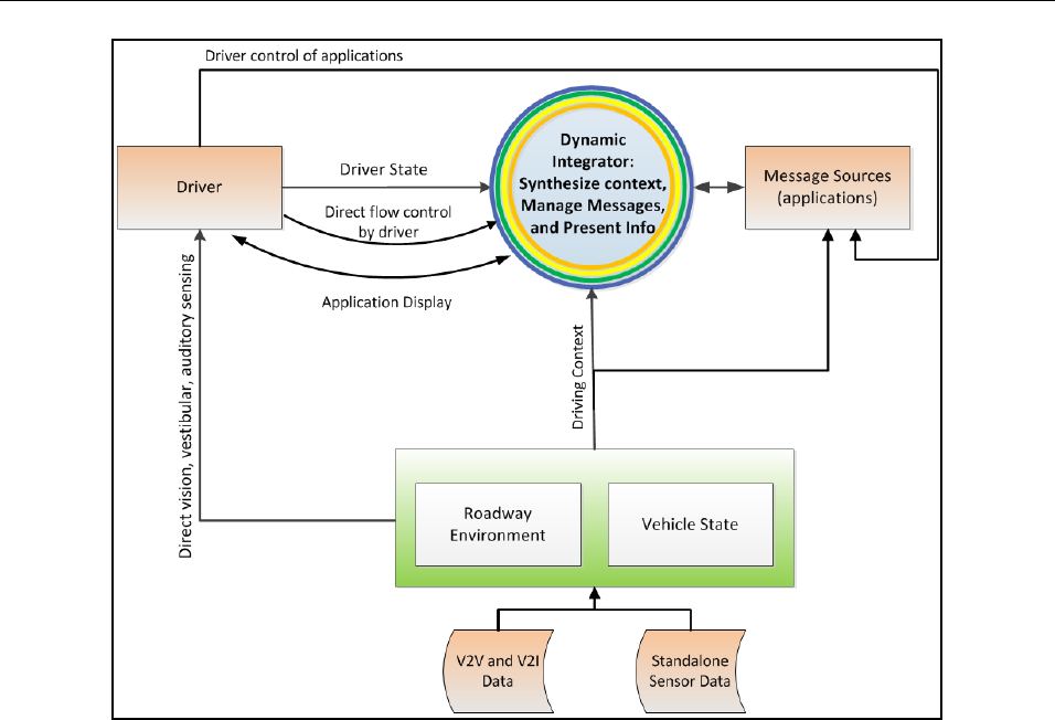
DVI DESIGN GUIDANCE TUTORIALS
12-24
Figure 12-2. Context diagram for Connected Vehicle integration process.
Direct input from the driver to the Dynamic Integrator provides the capability to globally manage
the volume and type of information conveyed to him or her. That is, while the Dynamic Integrator
will control message traffic sent to the driver (based on an estimate of their ability to safely
receive the information), drivers may also be provided with the ability to configure the integrator,
further customizing this flow.
Illustrated by the two-way arrow in Figure 12-2, the Dynamic Integrator might also communicate
directly with applications in order to administer the flow of information to the driver. If such
application-level information management capability is exercised, applications will understand
and appropriately respond to a small, predefined set of information published by the Dynamic
Integrator. For example, it could publish information about the driver’s current workload. Under
high workload conditions, this information could be used by compatible applications to simplify
their desired message (e.g., a detailed message regarding the cause and duration of upcoming
traffic delays becomes “delay ahead”). This interaction should not be thought of as a detailed
conversation between the Dynamic Integrator and the applications, but rather as information
published by the integrator and accessible to the applications.
Numerous CV applications, all operating concurrently, create and submit messages to the
Dynamic Integrator for presentation to the driver. With consideration for the current context, the
Dynamic Integrator determines how to best present the information. This process is depicted
below in the exploded view (Figure 12-3) of the Dynamic Integrator and the associated three
primary integration tasks.
1. Synthesize Inputs
2. Manage Messages

TUTORIALS DVI DESIGN GUIDANCE
12-25
3. Manage Presentation
Messages are submitted to the Dynamic Integrator by applications. Once submitted, the messages
are stored (often for a very short period) in a queue for processing and arbitration. Metadata
associated with each message describes attributes that are used to determine message handling
strategies. The Dynamic Integrator also publishes additional data elements based on the current
driving and driver context. Elements of these data are available to applications and the processes
within the Dynamic Integrator. In combination, these data provide a set of attributes that enables
the applications and Dynamic Integrator to collaboratively make informed decisions about what
and when to present. The applications control which messages are submitted based on their
detailed algorithms and the Dynamic Integrator determines if presentation is appropriate given the
overall driving context. When the combined metadata satisfies all criteria of the Manage Messages
process, the message is presented to the driver on an available DVI. This Dynamic Integration is
performed by three primary processes:
Figure 12-3. Exploded view of the dynamic integrator (within the blue box) illustrating
management of three aspects of the integration architecture: synthesis of input,
management of message traffic, and presentation of information to drivers.
• Synthesize Inputs. In this process, details of context are determined through a synthesis of
various driver, roadway environment, and vehicle data. These data may be used by the
integrator to make informed decisions during the Manage Messages and Manage
Presentation processes detailed next. Generally, the data will be synthesized to estimate the
driver’s ability to safely perceive, recognize, and respond to the message, a construct

DVI DESIGN GUIDANCE TUTORIALS
12-26
referred to as available workload. Such an estimate may be based on a variety of measures,
such as traffic density, speed, last interaction with the DVI, radius of roadway curvature, and
perhaps direct driver monitoring systems, when available. Additional inputs synthesized may
include, but are not limited to, the driver’s configured integration and application settings
(discussed previously) and predicted needs/goals of the driver and vehicle.
Driver needs represent the system’s estimate of what type of information the driver desires.
Intelligent in-vehicle systems may interface, for example, with the user’s smart phone or
cloud computing data center to download content about their daily schedule. This content
may help the Dynamic Integrator make informed decisions regarding which messages the
driver prefers to receive. Similarly, the vehicle needs represent information that the vehicle
needs to convey to the driver to ensure vehicle reliability (or possibly other priorities). For
example, if the vehicle is low on fuel, the Dynamic Integrator could use this information to
elevate messages pertaining to upcoming fueling opportunities.
• Manage Messages. The Manage Messages task is at the heart of the Dynamic Integrator and
is the primary focus of this tutorial. During this task, messages are arbitrated to determine
which might be filtered (i.e., discarded for current time step), dynamically adjusted in
relative priority, and scheduled for presentation to the driver. Details of this process are
further broken down in Figure 12-4, which depicts how a message must pass through each of
these three processes before presentation.
Figure 12-4. Connected Vehicle dynamic integrator model.
− Filter. Messages that are not appropriate, given the current driving context, may be
immediately blocked and not processed by the remaining integration stages for the
current processing cycle (they may be reconsidered by the process at the next time
step). Filtering will occur based on user settings or when driving conditions indicate
it is unsafe to provide a given message.
− Prioritize. When numerous applications are operating, multiple messages may be
simultaneously submitted. This is particularly true if a long message or string of
interactive messages has been blocking access to the DVIs (e.g., driver is actively

TUTORIALS DVI DESIGN GUIDANCE
12-27
navigating a menu structure on the DVI). When multiple messages are cleared by the
filter, a prioritize process will determine the relative importance of the messages and
assign presentation order accordingly. Priority ordering itself, however, does not
exclusively determine when a message will be presented.
− Schedule. Timing is the function of the scheduling process that assesses the metadata
and context information to determine when each message should be presented. This
process controls message cadence and ensures that drivers maintain the capacity to
receive information while focusing on the primary task of driving. In some cases, the
schedule process may allow certain high-priority messages to interrupt lower priority
messages (e.g., in the case of an imminent safety warning). The process also has the
ability to schedule messages of equal priority at or near the same time, particularly if
their presentation strategies allow the driver to process both messages effectively
(e.g., using two different display modalities).
• Manage Presentation. In this process, messages that have been cleared for delivery are
analyzed and distributed to the appropriate DVIs for information rendering. The Manage
Presentation process tracks the use of all DVIs and publishes the information for the
applications and the Manage Messages process to use. This status information contains
details of which applications are currently using the DVI and, when allowed by designers,
which types of other applications may share access. For example, consider a navigation
application that is displaying map content across the large center stack screen. The Manage
Presentation process may have provisions for allowing a small overlay to appear in the
screen corner; which can, for example, display the current speed limit as populated from an
in-vehicle sign application.
Overall, messages are submitted to the Dynamic Integrator by applications with the intent of
conveying a message to the driver. While there are a number of processing steps, ultimately, the
Dynamic Integration results in one of the three following outcomes for each of these messages:
1. Send the message straight through for immediate presentation.
2. Delay the message resulting in:
i. Later presentation.
ii. No presentation when message becomes obsolete.
For presented messages, the Integration Architecture facilitates appropriate display of content on
the available resources. It is important to note, for simplicity, the Integration Architecture is
presented as a set of steps that may appear to be sequentially executed. Although useful for
exposition clarity, many of these processes are actually conceived as concurrent processes that are
event-driven. They are triggered by message transmission, refresh cycles, or changes in driving
context. Thus, all processes may act on messages asynchronously as they arrive, or synchronously
with a defined evaluation cycle. As with many vehicle-safety systems, it is expected that the
Integration Architecture’s evaluation cycles will occur many times a second; for example, 10Hz
has been accepted as reasonable cycle time for CV safety-message transmission (SAE, 2010).
It should also be mentioned that the message queue, as depicted in Figure 2, is a storage location
in which messages are processed before they are cleared for display. During this processing,
messages are indeed prioritized as suggested by the name “queue”; however, the Integrator can
allow multiple messages to be presented during any one cycle (e.g., both messages meet the
necessary criteria for display and do not conflict with each other). There is not a one-to-one
relationship between a full Dynamic Integrator refresh cycle and the presentation messages.

DVI DESIGN GUIDANCE TUTORIALS
12-28
With the full system context provided by this overview, the remaining portions of the tutorial will
focus in on the details of individual components to further clarify operations. This will begin with
a discussion of the applications and subsequently trace through each process of the Integration
Architecture.
4 Message Sources (i.e., Application Processes)
Applications for the CV can address topics from traditional transportation areas such as safety,
mobility, and environment to newer areas such as convenience, entertainment, and marketing. The
Dynamic Integrator cannot be tasked with knowing and evaluating the low-level details of each
application or the content of the messages that they produce. Instead, the Integrator must be
directly provided with specific information about the data it will handle. That is, it relies on
metadata associated with messages. This metadata, described later in this section, contains key
pieces of information that provide the basis for message arbitration and display. The majority of
the metadata is statically determined during application design with limited additional metadata
determined dynamically.
As indicated previously within Figure 2, applications submit messages and metadata to the
Dynamic Integrator, where it is inserted into a queue with other submitted messages. While in
queue, the metadata is analyzed by the Dynamic Integrator with consideration for the present
context. The results of this analysis are published for other processes, including the application
process itself. For example, the filter process within the Manage Messages task may determine
that a message is too complex for display, given the current context. At this time, it will update the
message status indicating rejection for complexity. This Message Status, in turn, may be read by
the application that can wait for the message to be accepted (when the current context is more
favorable), cease message submission, or perhaps resubmit a simplified message, if available.
Such message tailoring may also be performed prior to submittal to the Dynamic Integrator queue.
For example, information published by the synthesize inputs and presentation processes might be
presented to applications in order to inform the application’s messages-creation process. More
specifically, the synthesize inputs and presentation layers can make a limited set of attributes that
reflect the current driving context (or driver state) available to the applications (dashed lines in
Figure 2). This provides applications with awareness of the current capacity of the driver and
availability of interfaces; which may help determine which messages should be submitted. An
application could then adjust its message output (e.g., simplify content) to increase the likelihood
that it will reach the driver without being filtered or delayed. Enabling of this functionality is
predicated on the assumption that applications appropriately respond to such published
information and do not artificially manipulate, for example, their metadata to alter the priority of a
given message.
Applications are likely to post messages around the time they should be displayed. Consequently,
messages should normally flow as quickly as possible through the integrator, resulting in a display
to the driver. However, if displays are shared by applications, they may occasionally be
unavailable (e.g., locked out due to a higher priority message). There may also be occasions in
which a delayed message remains in the queue sufficiently long that it becomes irrelevant (e.g.,
“rest area ahead” message once the window for taking the exit has been passed). The application
can stop submitting messages that become irrelevant prior to display.
Another important distinction in applications relates to the origin of a message: solicited versus
unsolicited. Solicited messages include applications such as tuning the radio, wherein each

TUTORIALS DVI DESIGN GUIDANCE
12-29
message is provided in response to a specific driver request. Unsolicited messages are presented
without a direct request from the driver. These unsolicited messages are common across the
envisioned CV applications, and may provide information ranging from services at an upcoming
exit to unexpected traffic delays on the roadway ahead. While collision warnings (a type of
unsolicited message) have considerable research support, the impact of other types of unsolicited
messages on driver performance is not well understood. Caution should be exercised to ensure that
such messages do not inappropriately distract the driver.
Messages may vary considerably in their content and complexity. A simple message may update
the artist’s name on an internet radio station located on a small display within the instrument
panel. More complex messages (e.g., upcoming traffic delay or new route suggested) may
subsume an entire display. Such complete control of a display by an application is likely when a
driver is performing an ongoing or multi-step interaction (e.g., navigating a menu structure).
During these scenarios, the Message Management can help ensure that messages do not
inappropriately interrupt the interactive activities.
To enable these integration processes, the messages must include information that enables the
Message Management to make decisions. This information, appended to each message by its
associated application, is referred to within this tutorial as metadata and is further described next.
4.1 Message Metadata Overview
A list of metadata can be associated with each CV message submitted by an application. It
provides the information needed to properly filter, prioritize, schedule, and present the message.
Such a list of metadata is thus likely to consist of two sub-parts: (1) a list of values that are
established in advance (at the time messages are developed and tested for use within the CV
system); and (2) a list of values that may be established in real-time as the vehicle is being driven,
based on certain values acquired from vehicle, infrastructure, or driver data. To assist in
visualizing this, it might be graphically depicted as, literally, a list of data fields (Figure 12-5).
Figure 12-5. Hypothetical diagram of a list of metadata accompanying a CV message.
The colored boxes above are intended to represent metadata fields that carry values of variables.
The first six fields in the list above (yellow, green, turquoise) might, for example, represent the
pre-computed values (determined by testing done in advance on CV messages, and stored as an
embedded part of each CV message). The second six colored boxes in the list above (dark-red, tan,
lavender) might represent values that are derived in real-time by the applications.
The static metadata construct is not new as evidenced by methods used to characterize message
priority offered by both the Society of Automotive Engineers (SAE, 2002) and the International
Organization for Standardization (ISO, 2004). In these procedures, the following message
metadata are explicitly quantified:
• Safety relevance (SAE)/Criticality (ISO). This is the degree to which the receipt of the
message affects the safe operation of the vehicle. SAE distinguishes three levels of safety
relevance (directly, indirectly, and not relevant). ISO distinguishes four levels of criticality
(severe or fatal injury, injury or possible injury, no injury but damage likely, and no injury or
damage likely).

DVI DESIGN GUIDANCE TUTORIALS
12-30
• Operational relevance (SAE only). This identifies the degree to which the information
increases the ease or convenience of the driving task. Three levels are distinguished: highly
relevant, moderately relevant, and not relevant.
• Time frame (SAE)/Urgency (ISO). This identifies the degree to which the information is
time-sensitive in the sense that it reflects the time in which the driver must see the message,
presumably in order to take appropriate action. SAE distinguishes five levels of time frame,
and ISO distinguishes four levels.
These standards provide a reasonable starting point that might be leveraged to establish a priori
baseline message priorities. They are, however, currently limited in their ability to specify how
these factors are assigned and weighed to determine a message’s instantaneous priority in a
constantly changing real-time environment. This is particularly true in the CV context, wherein
numerous messages are arbitrated in an ongoing and context-dependent manner. Several other
kinds of metadata about messages might also help in the management and control of how and
when a message is presented to a driver.
There has been very limited previous literature and discussion of the ways messages might be
characterized to permit successful DVI integration. Traditionally, most messages are simply
displayed immediately and on a single interface/format. This does not consider future vehicles,
and particularly CVs, in which an ongoing dialog of messages may be received by the driver
across several different interfaces. The effort needed to characterize and enumerate the various
attributes of messages relevant for successful integration is a reasonable ongoing research
program. However, at present, there is sufficient knowledge to suggest some metadata elements
for consideration, the use of which will be demonstrated through the subject Integration
Architecture.
In most instances, the elements are determined ahead of time, when a message is developed—and
when it is tested by its developer to make sure that it meets relevant human factors guidelines that
are applicable. It is assumed, for example, that messages to be presented within a CV system
would be pre-tested for their compliance with applicable distraction guidelines, such as the
recently released NHTSA guidelines that may be voluntarily applied to visual-manual interfaces of
vehicle-embedded electronic devices (NHTSA, 2013).
4.2 Exemplar Message Metadata
Table 12-9 provides a summary of possible message metadata followed by a brief description of
each data element. It is the purpose of this table and the subsequent descriptions to provide
example metadata elements for consideration by designers to be used in the subject architecture.
This is by no means a complete list, nor is it universally applicable, appropriate, or justifiable for
every CV platform. The reader is reminded that this tutorial is being drafted to assist designers in
the development of a Dynamic Integrator, not to provide a generically useful and validated
integration method or a detailed implementation design.

TUTORIALS DVI DESIGN GUIDANCE
12-31
Table 12-9. Possible fields of message metadata for CV messages.
Field
Set
Description
Coded Levels
Processed By
Sources
1
A priori
ID
• Unique Message ID
• All
2
A priori
Application Type
• TBD – platform specific
• Filter
•
Prioritize
3
A priori
Message Type
• Safety
• Mobility
• Environment
• Entertainment
• Social Networking
• Services/Marketing
• Filter
• Prioritize
• Schedule
• Present
NHTSA,
2011
4
A priori
Origin
• Solicited
• Unsolicited
• Prioritize
Holmes
et al., 2013
5
A priori
Safety Relevance
• Yes-Direct
• Yes-Indirect
• No
• Prioritize
SAE, 2002
6
A priori
Time to Respond
• Time measured from testing
• Schedule
• Present
A priori
Message
Demand
• Additional workload imposed by
message
• Filter
• Prioritize
7
A priori
Target DVIs
• Specifies the DVIs to display message
and indicates whether each DVI is
required or optional.
• Schedule
• Present
8
Dynamic
Expiration Time
• Time
• Prioritize
SAE, 2002
9
Dynamic
Message Age
• Time
• Prioritize
1. Message ID. This field would contain a unique identifier for a message. It is used by the
Dynamic Integrator to address messages during processing.
2. Application Type. This field identifies the type of application generating the message. It
may be used to enable user filtering of particular types of information as well as several
other processes of the Dynamic Integrator; as described later in this tutorial.
3. Message Type. This field would contain a classification of message type based on message
content. It may be used to enable user filtering of particular types of information as well as
several other processes of the Dynamic Integrator; as described later in this tutorial.
4. Origin. This field identifies whether or not the message is a direct result of a request from
the driver. In the absence of any other priority, messages that are solicited will be presented
prior to unsolicited messages.
5. Safety Relevance. This field would contain a code that reflects the SAE Safety Relevance
(as discussed above). The other components (operational relevance and time sensitivity) of
the SAE J2395 will be computed during the prioritize process based on real-time data (see
Figure 12-9).
6. Time to Process and Respond to Message. This field carries a measure of time that reflects
the actual time period a driver needs to receive the message (read it or hear it or otherwise
sense it), process it for comprehension, and then respond to it, all without compromising safe
driving.
7. Message Demand. This field carries a measure of the amount of additional demand imposed
by processing and responding to the message (which would be assessed at the time of its
design and development).

DVI DESIGN GUIDANCE TUTORIALS
12-32
8. Target DVI Address. There are significant differences in the constraints imposed on the
integrator by a message’s DVI requirements. Two audio messages, for example, cannot be
presented simultaneously without the risk that one message might mask another. On the
other hand, visual displays can present more than one piece of information at the same time,
provided they do not occupy the same display screen area. This metadata element can
include multiple DVIs (and modalities), along with indications of whether each DVI is
required or optional. This will ensure that messages requiring multiple DVIs are presented
appropriately (e.g., collision warning on both audio and visual displays). It will also allow
other types of messages to have a flexible display method (e.g., use auditory if available, but
to only use vision when unavailable, like when the driver is listening to music).
9. Expiration Time. To enable the Message Manager to act in a way that is consistent with the
SAE J2395 notion of urgency, this field, provides the message “shelf-life”. Some messages
may have limited relevance as time passes, while others may be relevant for an entire trip. If
such messages are buffered or delayed in a queue, they may become irrelevant over time.
Some messages may become irrelevant as a vehicle passes out of an area. For example,
warnings about an icy roadway surface may apply to a limited section of a roadway. Once a
vehicle passes through the area, such a warning may become obsolete or even detrimental.
This data element is populated by the application based on the specific needs of the message
content and is updated in real-time based on data processed by the application.
10. Message Age. This field would reflect a measure of how long the current message has been
waiting in the queue. In the absence of a clear priority, messages will be presented in a first-
come-first-serve order.
5 A Dynamic Integrator Model
In a reiteration of an underlying message throughout this tutorial, the Integration Architecture
presented herein forms the basis from which developers may create a prototype Dynamic
Integrator. It partitions the processes and establishes a framework for a general approach that may
be widely adaptable; however, we should acknowledge that new approaches may indeed become
more suitable as application software and hardware platforms evolve. As such integration systems
become engineered and prototyped, it is certain that refinements and improvements will be made
to the material conveyed thus far and throughout the remainder of this discussion.
To assist developers with the realization of refined Integration Architectures, the following section
provides some additional discussion of the Dynamic Integrator parsed by its three distinct
processes: (1) Synthesize Inputs, (2) Manage Messages, and (3) Manage Presentation. This
discussion is accompanied by an example of a near-term Dynamic Integrator. This phrase “near-
term” implies the relatively simple structure and logic of this example. That is, the example
presented, with some research and development, could be deployed in the relative near-term;
however, it may provide a more conservative integration strategy than would be possible with
more research and implementation of a more sophisticated architecture. Within the discussion of
each process, the example is followed by additional considerations that may help designers work
toward a more capable integration architecture of the future.
5.1 Synthesize Inputs
The main purpose of the Synthesize Input process is to characterize the current driving context,
thus serving as the basis for the decisions of the Manage Messages processes. This current context
is parsed into four primary sub-processes, each of which measures or estimates key attributes of
the Dynamic Integrator:

TUTORIALS DVI DESIGN GUIDANCE
12-33
• User Configurations, which gathers system settings that control how and when messages
may be presented to the driver.
• Workload Estimation, which assess the driver’s ability to receive messages based on
prevailing conditions.
• Driver Needs Prediction, which predicts the goals and desires of the driver based on
information available (e.g., driving patterns, anticipated destination, and calendar downloads,
etc.).
• Vehicle Needs Prediction, which predicts vehicle systems that will need the driver’s
attention (e.g., low oil pressure, maintenance due, etc.).
Figure 12-6 provides an overview of the primary sub-processes within the Synthesize Inputs layer.
Each of these processes captures and analyzes data from multiple sources within the vehicle. In-
vehicle sensors collect real-time information about the vehicle state and can include:
• Chassis-related (e.g., braking, steering, vehicle stability, tire pressure).
• Safety-related (e.g., air bag actuation, seat belt, occupant presence, blind spot, lane
departure, parking, headway).
• Driver-related (e.g., steering, throttle, DVI interaction, system settings), roadway (e.g.,
traffic density, estimated curvature, roughness, etc.).
• Environmental-related (e.g., ambient light, ambient temperature, humidity, precipitation).
From these data, processes generate output useful to the management of messages in the
subsequent Dynamic Integrator layers.
Figure 12-6. Overall framework for the Synthesize Inputs layer.

DVI DESIGN GUIDANCE TUTORIALS
12-34
The User Configurations captures the current user-defined settings relevant to integration. The
driver is expected to have the ability to set certain filters, based on personal preferences. For
example, these filters might pertain to whether or not marketing messages will be allowed for
presentation. These data on configuration settings are stored on an in-vehicle system and, for the
purposes of this illustration, are captured as part of the in-vehicle sensor suite. The Dynamic
Integrator will access these settings when making decisions on whether or not a message should be
presented.
The Workload Estimation might combine information about the demands of the primary task
(e.g., the driver’s control inputs, traffic density, etc.) and secondary tasks (interface inputs, direct
driver monitoring systems, etc.) to estimate the total current workload. This workload estimate is
compared to the workload required by a pending message to determine whether the driver has
sufficient capacity to respond without impacting safety. Workload estimation in a real-time system
is complex and not particularly well-defined at the present state. Given its importance to the
presented model, additional discussion is provided in the next section (Section 5.1.1).
The Driver and Vehicle Needs Assessments may be computed from analysis of information such
as:
• Historical data (e.g., driving and interface use patterns).
• External devices (e.g., the key fob will identify the current driver, and the driver’s phone, if
linked, may upload calendar events, including purpose of current trip—such as driving to the
airport for a scheduled flight).
• Vehicle state sensors.
Driver Needs and Vehicle Needs sub-processes pull together data, which would otherwise remain
separate, in order to assist the Manage Messages process with intelligently determining if an
incoming message is of high operational relevance for the driver-vehicle system. This driver-
vehicle system must be considered as whole—driver-in-partnership-with-the-vehicle and in the
context of road, traffic, and environment. In the near-term, this may consist of using preset
relationships to identify scenarios in which the driver or vehicle needs match to a given message.
These “matches” could occur between message content and currently existing needs/states, or with
those that are emerging or projected (e.g., based on currently-driven route, for example, and/or
based on events that have been detected by CV sensors up ahead).
The Synthesize Inputs layer is charged with gathering information from various sources and
distilling it into content that may be used by the Manage Messages process. This distilled
information is application- and vehicle-platform dependent, which precludes detailed discussions
of the specific measures and algorithms applicable to these sub-processes. The user-configuration
sub-process is primarily a pass-through in which configuration settings of a specific system are
read and then provided to the Manage Messages process. The Driver and Vehicle Needs sub-
processes are highly dependent on the information available on a given platform (and may not be
part of the initial systems). Finally, the workload sub-process is central to the Integration
Architecture, and as such will be discussed in further detail below.
5.1.1 Exemplar Logic for Workload Estimation
The following section provides the logic for outputting an estimate of driver workload within the
Dynamic Integrator example. There are numerous driver workload estimators proposed in the
literature (Alders et al., 2012; Ohm & Ludwig, 2013; Prakah-Asante et al., 2010; Son & Park,

TUTORIALS DVI DESIGN GUIDANCE
12-35
2011; Yoon Sook et al., 2010; Zhang et al., 2004); therefore, this section will not propose a
specific method, but instead, provide the framework that a driver workload estimator should work
within.
A driver’s capacity may be best predicted by estimating the current driver workload through
analysis of available data from the vehicle, environment, and driver. Initially, such workload
estimates can be simplistically determined (e.g., vehicle static versus vehicle in motion) and
generically applied across messages, regardless of intended delivery strategy. As knowledge is
gained, these workload assessments can become more refined by considering numerous additional
measures and the relative demands on specific attributes of the driver’s perceptual, cognitive, and
physical resources. This could allow leveraging of driver resource capacity over a broad range of
driving contexts, thus allowing users to safely interact with the system more frequently.
Given the current state of knowledge, a near-term example of driver workload estimation
discussed in this section relies on simple estimates of the driver’s ability to receive messages
based on traditional vehicle sensors. This vehicle contextual data allows the output of the Dynamic
Integrator to be informed and responsive to the ongoing driving situation. After the example is
provided, a subsection is devoted to discussing additional considerations for future, more complex,
theoretical methods for estimating workload.
Figure 12-7 illustrates a hypothetical framework for the Synthesis Inputs layer. Driver State
includes a simple overall estimate and does not take into account differences across the driver’s
resources. Vehicle State includes estimates of vehicle dynamics and stability. Roadway
Environment State includes estimates of traffic density, roadway type, roadway surface conditions,
and ambient environmental conditions.
Figure 12-7. Hypothetical logic for synthesis for workload estimation.

DVI DESIGN GUIDANCE TUTORIALS
12-36
The primary outcome of the workload process is an estimate of the driver’s ability to safely
receive a message. This is computed as a measure of workload, or the extent to which the driver is
currently tasked, and provided to the Filter sub-process within Manage Messages process. This
process will use the estimate to determine whether a message should be forwarded to the next
process or blocked to avoid overwhelming the driver (raising the workload over a preset
threshold).
5.1.2 Additional Considerations for Synthesize Inputs
The Synthesize Inputs process deals with predicting driver workload in a real-time context based
on information available to the Dynamic Integrator; a topic that is not mature. As such, it is worth
discussing some additional considerations that could enable more accurate estimates of the
driver’s ability to receive messages. The applied synthesis example presented previously was a
simplistic representation of the driver’s resource capacity based on readily available inputs.
Wickens’ (2008) Multiple Resource Theory and other workload models might serve as a basis for
establishing a more complex message delivery technique that maximizes the driver’s cognitive
resources. Application of such workload models may allow for the presentation of multiple
messages simultaneously without compromising safety.
In its simplest form, a single load estimate might be sufficient to capture a driver’s current
capacity to respond to messages. This might, however, also be refined to distinguish different
kinds of driver loads such that some kinds of loads might be considered somewhat independent of
other loads (e.g., verbal versus perceptual; Wickens, 2008). For illustration, darkness might
increase perceptual load, causing the driver to focus more attention from the visual process to
compensate for reduced visibility, without affecting the driver’s ability to understand spoken-word
messages. This suggests that a more sophisticated version of Synthesize Inputs might manage a
multi-dimensional picture of a driver’s ability to process certain classes of information. Such
compartmentalization of driver processing capacity is rooted in a long history of driver workload
research (e.g., Engstrom, Johansson, & Ostlund, 2005; Lavie, 1995, 2005; Lavie, Hirst, de
Fockert, & Viding, 2004; Leibowitz & Owens, 1977; Recarte & Nunes, 2000).
The key purpose of this synthesis is to gain some idea of the degree to which the driver may be
able to receive and respond to messages. Roadway environments such as rough pavement, poor
weather, limited visibility, tight radius of curvature, and high traffic density will likely elevate the
level of focus needed by the driver to safely drive. Some of this roadway information can be
derived directly from CV message traffic, while others may come from vehicle sensors such as
speedometers, accelerometers, radar, and machine vision.
For example, either the number of basic safety messages or the number of radar targets could be
used as an index for traffic density; this, in turn, could be used to adjust the workload estimate. A
step deeper, the relative speed and speed variance of adjacent vehicles captured by these sensors
could be used as an indicator for traffic volatility, which could have additional implications on the
driver’s ability to receive messages. Additional measures of driver engagement, such as rapid
steering and lateral acceleration, could indicate windy roads that may be both demanding and
somewhat unforgiving due to limited sight distance. In such a situation, it may be prudent to
temporarily reduce message flow rate to that driver. Other examples could be given as well (e.g.,
rain-sensing wipers, if on, indicate the presence of precipitation in the roadway environment,
increasing load on the driver and a need to reduce message traffic to the driver, and so on).
Unfortunately, there is limited research to date that relates such driver, vehicle, and roadway
environment factors to the ability of a driver to receive messages.

TUTORIALS DVI DESIGN GUIDANCE
12-37
5.2 Manage Messages
The Manage Messages process arbitrates numerous application messages to determine whether,
when, and how a given message may be presented. The primary goal of this process is to control
the flow of information originating from multiple sources in a manner that ensures content is
safely displayed to the driver without being masked (or otherwise unnoticed) because of
competing content from another source. This is accomplished through the embedded filtering,
scheduling, and prioritizing sub-processes. Each of these processes analyzes specific elements of
the message metadata in consideration and the contextual data published by the Synthesize and
Presentation processes to control the message delivery strategy.
5.2.1 Filter Messages
The initial process within Manage Messages filters information so that messages are rejected if
they are either: (1) explicitly prohibited by the driver through a direct configuration setting; or
(2) impose an inappropriate level of additional load on the driver, given the current driving
context.
Filtering based on configuration settings. The first basis of filtering involves explicit
prohibitions that might be established by the driver. For example, a driver may wish to adjust
receipt of some classes of message, just like smart-phone users can configure either the phone’s
operating system or specific applications to suppress presentation of some notifications. To
accomplish this, the user may adjust the Dynamic Integrator configuration settings to suppress
messages based on individual applications, application type, message type, or other criteria as
desired. Filtering by application type requires assigning each connected vehicle application a class
designation. For example, applications like Instagram, Twitter, and Facebook might be classified
as social networking; applications relaying traffic operations data (e.g., lane closures, road
conditions, and/or travel time) might be broadly classified as roadway information. Filtering could
provide the driver with a means to independently suppress presentation of messages from all
applications belonging to one or more of such classes.
Because some applications could transmit a range of messages that vary in importance, it might
also be appropriate to implement filtering by message type. For example, a roadway construction
application might have a variety of messages ranging from long-range strategic (e.g., future
construction planned on current roadway in the coming months) to tactical (e.g., construction
flagman actively directing traffic ahead). By filtering on message type, the application may still
allow the tactical messages to be presented while blocking strategic messages.
Filtering based on estimated driver workload. The second reason to filter or withhold messages
from the driver occurs when the added demands of specific message delivery on a driver’s current
workload could elevate the risk of a traffic conflict. That is, if the message is likely to divert the
driver’s attention momentarily, it may increase the risk of overlooking important information in
the roadway (e.g., a car pulling out of a driveway). Unless the message is directly targeted at
improving safety, it might be reasonable to discard it and avoid the possibility of increasing crash
risk. An example of this filtering would be to restrict unsolicited notifications when driving in
volatile urban traffic.
Note that the filtering process need not directly “know” that the nearby traffic is dense. The
Synthesize Inputs process understands that traffic density affects the amount of targets a driver
must keep track of and establishes that the driver’s workload is high. Filter simply blocks
messages that are not permitted under specified workload levels.

DVI DESIGN GUIDANCE TUTORIALS
12-38
5.2.1.1 Exemplar Filter Process Logic
The chief purpose of the Filter is to determine, based on metadata and the driver’s current load
level, whether to block the message or to pass it along to the prioritize process. If a message is
blocked, no further processing of that message will occur until the next refresh cycle; in which the
filter will reevaluate the message based on the updated information. An example of a processing
logic is given in Figure 12-8.
The outputs of this process, for a message that is not filtered, are an update of the
Message_Filtered status to “no” and forwarding to the Prioritize Process. Messages that are
filtered have their Message_Filtered status set to “yes” and an associated reason of either “User
Configurations” or “Exceeds Workload,” depending on the filter enacted. Applications may read
this information and decide whether to cease submittal of the message or to continue to submit and
await a change in the filters to permit message passing.

TUTORIALS DVI DESIGN GUIDANCE
12-39
Figure 12-8. Example of a Filtering process applied to messages that are intended for the driver.
5.2.2 Prioritize Messages
Methods exist for determining static (context independent) message priority (SAE, 2002; ISO,
2004). The Prioritize process augments this assignment of baseline priority with considerations for
the current driving context to determine the real-time priority relative to competing messages.
Messages are essentially ordered by priority within the message queue before being passed to the
scheduling process; which will determine the exact timing of presentation.
In general, competing messages will be prioritized based on the SAE principles of Safety
Relevance, Time Frame, and Operational Relevance. For a given message, a real-time priority
order index will be computed relying on the definitions of SAE J2395 (2002) and then used to
determine relative message ordering.
Safety Relevance is the degree to which information affects the safe operation of the vehicle. It is
set a priori by developers in the design of the message and may take the standard three levels of:
• Directly Relevant. Information contains direct safety information. Includes any item that
has as its primary purpose communication of information that is designed to reduce the
likelihood that the driver/vehicle and/or other driver/vehicle and/or pedestrian will be
injured/damaged.
• Indirect/Somewhat Relevant. Information is not directly safety relevant as defined above.
However, the information, if processed and responded to by the driver, may reduce crash risk
by reducing error or exposure.
• Not Relevant. Information item is neither directly nor indirectly safety relevant as defined
above. No known change in crash risk due to the presence of safety information, a change in
exposure, or a change in safety-related driver error.
Time Frame is computed in real-time by the prioritize process based on the expiration metadata
computed by the application. Essentially, message expiration metadata contains a countdown
timer that represents the remaining time window in which the driver is expected to respond to the
information provided. Thus, messages that will become irrelevant sooner will migrate to the top of
the queue. Time Frame, or the immediacy with which the information is required, is clustered into
the standard bins by the prioritize process.
• Immediate: 3-10s
• Near Term: 10-20s
• Preparatory: 20-120s
• Discretionary: >120s
Operational Relevance is also computed in real-time by the prioritize process; however, its
formulation is not as refined. Operational relevance is computed based on data from the message
metadata and Synthesize Inputs process. The message metadata Message Type and Origin
(solicited versus unsolicited) is compared to the Driver and Vehicle Needs provided by the
Synthesize Inputs process. The prioritize process analyzes the two sources of information looking
for, and assessing, the strength of “matches” between the purpose of the message and the needs of
the driver and/or vehicle. The matches are then inserted into the following classifications, which
represent the degree to which information increases the ease and convenience of the driving task:

DVI DESIGN GUIDANCE TUTORIALS
12-40
• Highly Relevant. Information that, if not received, will cause the driver
inconvenience/expense such as delay, error, or vehicle damage.
• Moderately Relevant. Information that is not highly relevant, as defined above. It may
improve the ease and convenience of the driving task, but will not likely result in
inconvenience or expense to the driver if not present.
• Little or No Relevance/Significance. Information that will not impact the ease and
convenience of the driving task.
The formulation of safety relevance, time frame, and operational relevance allows the standard
Priority Order Index table [Tutorial 2 and SAE J2395 (2002)] method to be applied to all
messages in the queue. After application, the queue will be rank-ordered by priority. In some
situations (e.g., multiple messages containing similar content are submitted), priority ties are likely
to occur. In general, these ties will function on a first-come-first-served basis with the oldest
messages being presented first.
5.2.2.1 Exemplar Prioritize Process Logic
The chief process of Prioritize is to determine, based on metadata and context data, the relative
importance of messages in queue. This dynamic prioritizing determines the order in which the
scheduling process will select messages for analysis and presentation. An example of a processing
logic is given in Figure 12-9.
The prioritize message output is an ordering of the messages in the queue. This relative priority
determines the order in which messages will be processed by the Scheduling layer. In addition, the
dynamic priority order index is published in the message status information so that applications
may read this information and act on it if desired (e.g., if message index is high then perhaps the
message should not be presented).

TUTORIALS DVI DESIGN GUIDANCE
12-41
Figure 12-9. Example of a Prioritize process applied to messages that are intended for the driver.
5.2.2.2 Additional Discussion of Prioritize Process
Although presented simplistically, dynamically prioritizing a message is actually a rather complex
endeavor. In Figure 12-9, the Estimate Operational Relevance process is the least understood, and
yet one of the most important, component of the ordering. The ability to accurately and precisely
compute a representation of relevance will require a thorough understanding of how the needs of
the driver and vehicle map to the message type and origin. Determination of these relationships is
dependent on some system-specific details, such as the ways in which driver and vehicle needs can
be measured and represented. Ultimately, researchers and developers will need to create a strategy

DVI DESIGN GUIDANCE TUTORIALS
12-42
that links specific message types (which need to be defined) to specific needs (which also need to
be defined).
There is also some question as to validity of the SAE priority index in this untested real-time
application. While the method has face-validity, there may be differences in the real-time
application that are not considered by the standard. For example, the real-time system has the
ability to compute a continuous measure of Time Frame. Perhaps it would be better to compare
priority on this continuous measure instead of lumping time into the four distinct buckets. A
similar argument may be made for Operational Relevance, which may have more than three levels
and perhaps be translated into a continuous measure (e.g., percent relevant) to permit finer-grained
decisions. Safety Relevance could have more than three levels, as well, and perhaps even be set in
real-time, based on specific conditions. It could be useful for non-imminent safety applications
that may have a varying level of safety relevance depending on, for example, the roadway
temperature and humidity in a slippery road application.
There are some scenarios that provide an argument to suggest that more complete models should
be investigated. For example, research has demonstrated that occurrence of multiple imminent
safety warnings is unlikely (Sayer et al., 2011). However, with the proliferation of additional
collision avoidance applications in a CV deployment, the likelihood of simultaneous warnings will
increase; particularly during evasive maneuvers when several different warning thresholds may be
surpassed. There are indications that presenting multiple imminent safety warnings may have
benefits when the directionality of the threat is conveyed (Lerner et al., 2011). In such situations,
however, there are questions about whether the SAE model would correctly prioritize the message
since messages would likely have the same Priority Order Index value. Such fine-grain
adjustments may not be necessary, however, as benefits of dynamically changing the ordering of
imminent safety warning presentation based on roadway conditions has not been demonstrated
(Ward & Rahman, 2013).
5.2.3 Schedule Message
Message scheduling is the next step after prioritizing. This process determines the timing of
message presentation by managing message cadence, based on current context and available
metadata. The process starts with the highest priority messages, which will generally be presented
in the same sequential order of the queue and at a rate that allows the driver to remain focused on
the primary task of driving.
In general, message scheduling is governed by analysis of recent messages presented to the driver.
Conceptually, for any given message, there is a certain amount of time required for the driver to
safely perceive the message, recognize its meaning, and perhaps execute and/or complete a
response. This slack time is dependent on the way in which the message was displayed (e.g.,
modality and location) and the message/response complexity. Slack time also depends upon the
additional time needed for the driver to return focus to the driving task prior to delivery of the next
message.
High priority messages are relatively straightforward to schedule. In most instances, such
imminent safety messages will simply pass straight through the scheduling process for immediate
presentation to the driver. If multiple imminent safety messages are passed from the prioritize
process within a short window, the scheduling process may delay presentation of the subsequent
message. This would be done to ensure the highest priority message is not attenuated or masked,
which would undermine message perception and/or recognition. Once any safety message has

TUTORIALS DVI DESIGN GUIDANCE
12-43
been presented, subsequent non-safety messages may be delayed for some time to allow the driver
sufficient time to perform an evasive maneuver or other safety message response.
For most messages, scheduling is more focused on pacing the driver’s interaction with the DVI.
To mitigate distraction, as well as to ensure usability, it is important that drivers be provided with
sufficient time to return their attention from processing a message to the task of safely driving
before another message is presented. In general, messages should be scheduled with enough slack
time to allow the driver to attend to driving before being enticed to distraction by another
inappropriately timed message (Allen & Howe, 2013). In the context of solicited messages
occurring during continuous DVI interaction, scheduling is relatively straightforward; an
appropriate message is displayed immediately after the driver’s input makes the request.
Therefore, the driver’s rate of system input largely determines the message scheduling.
Perhaps the most important and least understood message type to be scheduled is the unsolicited
message. Unsolicited messages are traditionally related to the vehicle diagnostic systems; such as
low fuel and engine maintenance indicators. These messages are generally rare and benign; they
often require no immediate action; and are displayed in locations reserved for that information.
They can be readily ignored by drivers in the near term, but should eventually be noticed.
Connectivity is bringing about a number of new applications that may produce a variety of new
unsolicited messages, such as traffic delay ahead, appointment reminders, and in-vehicle signs.
Such applications, which can provide safety and non-safety information, are generally lower
priority but can be highly desirable.
The advantage of a low-priority message is the inherent flexibility of message timing. Generally,
such messages can be delayed until the driver has sufficient available resources to safely respond.
In some cases, a complex message (such as a video-message) could be delayed for long durations
(e.g., until the vehicle is at a complete stop and perhaps even with the gear selector in park).
When the message scheduler sets message delivery, it does so based on some indication from the
message’s metadata about the typical processing time a driver will need to comprehend and act on
the message. This assessment can be used to ensure that no potentially disruptive message is sent
to the driver while the previous message awaits a driver response. For example, auditory messages
take time to play to completion, and if they are complicated verbal messages, they could likely
take more cognitive processing time before an action is taken. It is important that the driver not be
sent another message while digesting the preceding message. The message scheduler makes this
determination before transmitting the next message to the Manage Presentation process.
Message integration is supported by these scheduling functions to ensure that safety critical
messages are dispatched quickly to the driver, while other messages are timed according to their
relative importance and the driver’s ability to safely receive a message.
5.2.3.1 Exemplar Schedule Process Logic
The chief process of Schedule is to determine (based on metadata, priority data, and presentation
data) when to present the next message in the queue. This process is accomplished by analyzing
each message in order, determining if a compatible DVI is available, adding slack time if
necessary, and submitting the message for presentation when appropriate. An example of this
schedule process logic is provided in Figure 12-10.

DVI DESIGN GUIDANCE TUTORIALS
12-44
Figure 12-10. Example of a Schedule process applied to messages that are intended for the driver.
The primary schedule output is a decision on when to present the next message. Once an accepted
message has been scheduled, it is forwarded to the presentation layer for immediate presentation.
This layer does not block a message, but rather routes it to its intended interface. When a message
is forwarded, the Message Status is updated to indicate a Time_To_Present of zero. When a
message is delayed, it is scheduled for the next available slot and the Time_To_Present is
populated with the estimated presentation time, based on information from the Presentation Layer.
This information may be used by the application, which can choose to act on the content if desired
(e.g., retract the message if it will not tolerate message delay).
5.2.4 Additional Considerations of the Scheduling Process
Portions of the Scheduling Process, such as waiting for the slack time to pass, provide explicit
methods for controlling message cadence. However, the process as described above also has an
implicit bottleneck for the rate at which messages may be presented. More specifically, the

TUTORIALS DVI DESIGN GUIDANCE
12-45
scheduling process is designed such that it assesses each message in order. This assessment can be
made very quickly, perhaps faster than applications submit messages. As such, it is certainly
possible for multiple messages to be presented over a short time period, and perhaps distributed to
several different DVIs.
Consider this multi-message context in which several ordered messages in the priority queue await
scheduling. The scheduler analyzes message “1” and sends it to visual DVI “A”. This first
message expects the user interaction and remains on the visual DVI indefinitely awaiting input;
however, the driver does not respond to the message. Message “2”, which requires access to DVI
“A” for visual display and DVI “B” for auditory display, is processed next. Since DVI “A” is
locked for use by Message “1”, Message “2” is delayed. While message “2” is delayed, there are
two possible alternatives for processing Message “3”, which is an auditory only message seeking
the use of DVI “B”.
• Block Message “3” from using DVI “B” since Message “2” requires both DVIs and DVI
“A” is locked. This ensures the priority order is maintained; however, it creates a bottleneck
for messages since both DVI “A” and “B” are blocked (even though DVI “B” is not actually
in use).
• Allow Message “3” to surpass Message “2” and access DVI “B”. This allows more messages
to be delivered; however, it results in a priority change that is not controlled by the prioritize
process. Furthermore, there is a risk that Message “3” will tie up the DVI “B” after message
“1” has cleared from DVI “A”. This results in additional delay for Message “2”, which could
be compounded by additional single-DVI messages surpassing Message “2” and locking
either DVI.
The impact of this bottleneck depends on the breadth of the system, the design and allocation of
the DVIs, and the frequency of messages. The issue can be mitigated with careful design that
minimizes the number of multi-DVI applications to a limited set (i.e., safety critical messages). In
addition, this issue can be addressed in some instances by allowing messages to either interrupt or
to share the DVI. Additional discussion on the topic of interruption and DVI sharing is provided in
a special section later in this tutorial.
5.3 Manage Presentation
Beyond managing the flow of message information to a driver, it is also important to recognize that
this information may be presented on various visual displays, played through the vehicle’s audio
system, or delivered as a haptic signal through the seat, steering column, or other vehicle component.
Information may also be relayed to the driver over a period of time, involving multiple related
messages to fulfill a prior request (e.g., multi-screen messages displaying a series of traffic advisories
up ahead) or interactive procedures to accomplish other goals (e.g., interactive toll payment screens
that provide several payment options). Such operations might be vulnerable to disruption if unsolicited
messages are allowed to interrupt the operation before it is completed. The Manage Presentation task
monitors and publishes display status information to the Message Management process to permit
decisions about when to schedule messages based on DVI availability.
The Presentation Management process accepts messages once they have been cleared for delivery
by the Manage Messages process. Using the message metadata, the Presentation Management
process publishes information about DVI availability, based on the applications and messages that
are, and have recently been, displayed. For example, if the current message on a DVI is a multi-
step process in which the user will have an ongoing interaction, the display will become
unavailable to other applications (with the exception of a high priority, interrupting message).

DVI DESIGN GUIDANCE TUTORIALS
12-46
A simple example of this is an internet radio application, which may consume an entire display
with status information (station, artist, song, etc.) for an indefinite amount of time. The time for
which an application has access to a display is based on the metadata; however, the presentation
process is responsible for locking out the display, based on this information.
In addition to publishing DVI-related data, the Presentation Management process also distributes
content to the vehicle’s available displays; with the intent of creating a seamless user experience
while enhancing driving safety, utility, and enjoyment. Message routing is determined by the
message metadata, which includes elements about which DVI the message may be presented on.
As discussed in the metadata section, the DVI has provisions for a single message that must use
one or more DVIs as well as provisions that allow a flexible message to present on one of several
DVIs, depending on availability.
5.3.1 Exemplar Presentation Process Logic
The chief purpose of the Presentation Process (Figure 12-11) is to determine, based on metadata and
schedule requests, what message to render, and on what DVI to render it. The process then forwards
the message to the DVI, keeps track of the DVI availability and publishes it to other processes.
Figure 12-11. Example of a Presentation process.

TUTORIALS DVI DESIGN GUIDANCE
12-47
The presentation process output is a rendering of the desired message on the appropriate DVI.
When this rendering occurs, information for each DVI is published about
Availability_Last_Message, and Time_From_Last_Message. These published values are used by
the filter and scheduling processes to determine whether the resources are available to present the
information, and to determine when it is appropriate to present the next message, based on the type
and timing of the last message presented.
6 Additional Considerations for the System
The following section provides an overview of a few additional areas that should be considered
when developing a Dynamic Integrator. This content does not necessarily map to any one specific
process, but rather provides some important information that should be considered in light of a
specific implementation.
6.1 Message Interruptions and DVI Sharing Between Messages
As alluded to a few times throughout this tutorial, it is possible for multiple messages to be
presented at the same time. The decision to present multiple messages is made by the Dynamic
Integrator and is based on the metadata and the context/status information published by the
Synthesize Inputs and presentation layers. There are three ways in which multiple messages can be
presented:
1. Multiple messages may be presented across different DVIs; one message per DVI.
2. A higher-priority message may interrupt a lower priority message on the same DVI.
3. Multiple messages may share a single DVI.
In the first case, designers need to ensure that metadata is configured such that compatible
messages may be readily permitted for display at the same time, based on their DVI assignments.
For example, it is likely acceptable for a simple icon on the dash regarding the need for an
upcoming oil change to be presented at the same time as an in-vehicle sign on a center stack
display. On the contrary, it may be confusing, and possibly more distracting, if a voice-based
auditory message about slick roads is presented at nearly the same time as a visual message about
an upcoming dining opportunity. The ability to display multiple messages on different DVIs is
readily supported by the architecture. With thoughtful design, it should be feasible to designate
DVIs for particular types of information to facilitate a consistent mental model for the driver, as
well as limit the likelihood that two messages will both need a DVI at the same time (e.g.,
designate one specific display for short-duration messages so that long interactions do not block
access).
While interruptions should be avoided in most cases, it may be reasonable to interrupt a message
when critical information needs to be provided. The appropriate example is during the execution
of a collision avoidance warning, which may need to interrupt in order to provide sufficient time
for the driver to execute a successful evasive maneuver.
Interruptions, however, are not as simple as taking control over a given DVI in the context of a
collision warning or other high-priority message. With a limited number of DVIs and a potentially
large number of applications, it may be necessary to allow medium, and perhaps even lower,
priority messages to interrupt a message from an application. For example, consider the case
wherein a central DVI is displaying status information for an internet radio station (e.g., artist
name, song name, etc.). When the driver executes the internet radio application, they are likely to

DVI DESIGN GUIDANCE TUTORIALS
12-48
leave the status content on the display, rather than return to a home screen where other content
may be readily displayed. Although the driver opted to leave the status screen active, s/he may not
be opposed to, and indeed may desire, the display of other relevant information. The metadata
(such as the message response time element) may be used to control these low-level interruptions;
however, caution should be exercised to ensure the architecture supports this design without
unintended consequences and in a manner that does not distract or annoy the driver.
In some cases, it may be best to interrupt the message and consume the entire display (e.g., for a
safety message). In these instances, the initial application message should be interrupted to convey
the high-priority message in a salient fashion; this will maximize the opportunity for the driver to
perceive, recognize, and respond appropriately. The interrupted application should simply pause
until the interruption has been completed (and any slack time has elapsed as controlled by the
schedule process; Allen & Howe, 2013). Research has shown that interruption strategy can impact
driver performance (Holmes et al., 2013). Using partial-screen interruptions (in which the
interruption is overlaid on the original content with the original content in the background) may
improve the driver’s ability to re-engage in the original task after the interruption is complete.
When feasible, it may also be better to interrupt using a different modality (i.e., auditory message
when the driver is performing a visual task; Holmes et al., 2013).
In the majority of situations, it may be more appropriate to identify methods for sharing the
display surface real estate between multiple messages. Consider a display that is showing a map
for a dynamic routing application. A small segment of this display may permit additional
messages to be displayed in parallel. For example, a small display segment in the upper-left corner
may allow simultaneous display of in-vehicle signage, such as the current speed limit or upcoming
lane closure. Such multi-message DVI capabilities will need to be carefully designed and tested to
ensure driver performance is not negatively impacted. Each layer of the integration architecture
will need to be designed to use the shared DVI in a logical and user-accepted fashion.
6.2 Message Delivery During Driving
Not only is it important that a message be within the capacity of a driver to process and to respond
to, but it is also important that an additional evaluation be performed to determine how a
message’s delivery will impact the driver’s executive processes. This goes beyond the matter of
one message interrupting another, by instead focusing on the interruption any message creates
when it is presented during the primary task of driving.
Even if s/he is not performing secondary tasks, the driver is always multitasking when they drive
(e.g., managing the scan of the roadway view, the control of the vehicle’s lateral position, and its
longitudinal speed and separation from other vehicles). Thus, it is important for the Manage
Messages process to have rules governing interruption of the driver and their focus on driving
though message delivery.
This is an emerging research domain as it relates to drivers. However, in other domains, such as
aviation and human-computer-interaction, the management of interruptions has proven to be
critical to operator performance. Indeed, some of what is known today from these fields can likely
be applied to the development of Dynamic Integrators. Key resources may include: Latorella’s
Interruption Management Stage Model (cf., McFarlane & Latorella, 2002), as well as model-
driven work like that by Trafton et al., (2003) in which the goal-activation model (developed by
Altmann and Trafton; 2002) was used, and the Salvucci and Taatgen (2008) “Threaded Cognition
Model.” The notion underlying the Altmann and Trafton (2002) goal-activation model is that

TUTORIALS DVI DESIGN GUIDANCE
12-49
goals (the intention to perform some action in the future) are central to the way that people guide
their behavior, the way they process interruptions, and the way they resume tasks. To the extent
that a model can account for how a goal is affected upon message delivery and the way that it is
retrieved when a task is resumed (after it has been interrupted), it may provide a way to predict
behavior in the context of multitasking in general and in the context of driver distraction in
particular (Angell et al, 2010). Such a model may provide guidance for constructing part of the
“Manage” process.
Another interesting aspect of the goal-activation model is that it predicts that an interrupted driver
(who has been diverted from the driving task for a certain period, perhaps a few seconds) must
have “access to” or “be in the presence of” contextual cues in order to be able to return to the
primary task after an interruption or secondary task (Angell et al., 2010). In CVs, it will be
important to identify and separate messages that divert attention away from driving from those
that direct attention to the roadway and safety-relevant events. Some CV cues may themselves
actually serve as contextual cues that remind the driver to focus again on the driving task (and
hence, supporting and facilitating the driver’s attentional focus by essentially “strengthening” the
activation of goals that ideally would be in working memory).
6.3 Assumptions and Limitations
The Dynamic Integration architecture makes many assumptions about our understanding of the
driver and a future vehicle environment in which traditional and CV application messages are to
be managed to provide a safe and enriched user experience. This architecture is offered as a
starting place for designers to leverage while prototype integrators are developed. Ongoing
research and development, internal and external to the HFCV program, will allow for the
refinement of this architecture over time, reducing the present assumptions discussed in the
following paragraphs.
The Synthesize Inputs process has been discussed as a method for assessing the driver’s ability to
safely receive messages; which can be represented simply as estimating driver workload. This
workload can be estimated using relatively basic techniques today (e.g., workload is lower while
the vehicle is static than while driving in an urban environment). These basic techniques still
provide a powerful metric with which message handling decisions may be made. Moving forward,
more advanced models (which may move toward a comprehensive estimate of workload across
multiple resources) could provide the ability to more accurately determine when and how to
present messages. While such theoretical models have been discussed over the last 20 years, they
are not sufficiently mature to deploy within an integrator. More applied research is required to
understand how workload can be estimated using the available real-time data sources and how
such workload estimates correlate to safety risk.
The Manage Messages process is predicated on the assumption that all applications will route
messages through a centralized gate-keeping process. In present vehicles, displays are often
directly connected to specific application processors that do not share information with other
processors. These existing architectures do not lend themselves to an integrated DVI and will need
to be updated to enable the vision described herein. Furthermore, carry-in and other aftermarket
devices such as Smart Phones provide an illustration of the difficulty of integrating all CV
applications. For the purpose of this architecture, it has been assumed that such carry-in devices
have a handshake and become part of the integrated system; however, it should be acknowledged
and considered throughout design that this assumption may be violated.

DVI DESIGN GUIDANCE TUTORIALS
12-50
The Manage Messages process also assumes that each message is accompanied by metadata that
describes important attributes of the message to permit decisions regarding filtering, prioritizing,
and scheduling; this allows comprehensive message arbitration. Thus far, some existing
knowledge has been provided to inform portions of the metadata; however, much of the suggested
content was derived from engineering experts rather than arrived at from empirical research. Such
additional research will be required to validate the metadata’s relationship to the decisions
predicated, and, in some instances, this may even be necessary on each vehicle platform due to the
differences in applications and display technologies.
The assumption of standardized metadata is particularly important in the surfacing model in which
third-party vendors deploy applications on vehicle platforms; rather than on the integrated system
or through a carry-in device. The third party must adhere to the systems standards, otherwise
undesirable system behavior could result. Specifically, problems could occur if third-party vendors
used metadata to improperly boost their applications’ messages. As such, it may be necessary that
administrative controls are put in place so applications have to undergo a validation process before
they are allowed to reside on the vehicle.
It is also assumed that these metadata will be quantified in a systematic and consistent manner
across all CV applications that transmit such messages. Such consistency suggests the
development of governance strategies, and perhaps qualification/certification test methods, to set
each metadata parameter. For example, the current priority assignments may be based on the ISO
and SAE standards; however, these standards rely heavily on expert opinion. Perhaps more
objective methods leveraging user testing would provide values that result in better message
arbitration performance, particularly for non-imminent warnings in which baseline priority will
often appear equivalent.
The Manage Presentation process proposes an architecture in which multiple display resources are
shared among CV and non-CV applications. These multiple displays will each have certain
advantages relative to the messages. For example, some displays may be better located and/or
formatted for specific types of content. It is assumed that application metadata will allow the
Manage Presentation process to target the appropriate display; however, there are knowledge gaps
in which display technologies are best suited to each type of message content.
Lastly, the architecture presented here is focused on information flow and how to address a
driver’s processing bandwidth. It should be recognized that there are other integration issues not
addressed in the architecture, which can arise in an environment where multiple message sources
act independently. For example, systems that produce warning notifications often emit audio
warnings accompanied by flashing displays. While efforts are made to ensure these warnings are
distinctive, there is no guideline or standard in place to prevent a curve speed warning, for
example, from producing a sound similar to a forward collision warning or a cell phone
notification. This kind of integration is outside of the tutorial scope; however, it should be
addressed by designers and may lend itself to some industry standardization.
6.4 Discussion of Possible Future Research
Overall, future research should work to refine this proposed Integration Architecture based on
feedback from a broad stakeholder community. It is critical to understand how this tutorial will be
applied by the community, which elements are helpful for developing integration strategies, which
elements can be improved, and how, and what, additional information would be helpful in future
revisions. Presuming acceptance from the community, this research should lead to a refined

TUTORIALS DVI DESIGN GUIDANCE
12-51
version of the architecture that can be broadly disseminated with the intent of providing a
foundation on which developers can build their integration strategy, helping to ensure critical
design decisions are considered.
Throughout this tutorial, particularly within sections covering additional considerations, the need
for future research efforts within specific areas of the architecture was established. Although
details of these needs are best left within the context of those discussions, key future research
areas are briefly summarized in the sections below.
6.4.1 Applications, Messages, and Metadata
The architecture presumes that applications are refined and adhere to a set of prescribed rules. This
implies that applications are either developed by OEMs or are carefully reviewed by OEMs
through a certification process. However, there is a need for OEMs to allow more open-access to
applications, whether installed on the vehicle from third party vendors or though integration of a
carry-in device (e.g., smart phone). The ability to permit this open application architecture
deserves targeted research to investigate the efficacy of this approach as part of an integrated
system.
More open systems will require robust standards to ensure expected Dynamic Integrator operation.
For example, it is important that all applications use the same objective method to measure the
metadata element that defines the expected time required for driver response. If this measure is not
correct, the scheduling layer will make inappropriate decisions, perhaps resulting in distraction
from a rapid message delivery cadence.
Such standards will define what applications are permitted on the vehicle, how the applications
share information, what metadata is needed, how should such metadata be structured, how to
objectively and reliably compute metadata, and certification testing requirements and methods.
Such standards will ensure that messages are appropriately arbitrated by the Dynamic Integrator.
6.4.2 Synthesize Inputs
Successful application of the Dynamic Integrator is predicated on an effective prediction of the
driver’s ability to safely receive, and appropriately respond to, messages. Workload appears to be
the most mature construct for evaluating the driver’s capacity; however, the measurement and
application of workload in real-time is largely untested. Specifically, which measures of the driver
and vehicle can be used to objectively measure workload? Is the method of workload assessment
valid in its ability to predict capacity? Is it sufficient to assess workload along one dimension, or
does workload within each of the driver’s attentional resources channels need to be considered?
How many levels of workload are required, or should workload be measured along a continuous
scale? It is critical that links between the driver’s real-time workload and their ability to safely
receive messages is established?
Next, the Synthesize Inputs layer must be able to evaluate the requirements of a given message,
based on its metadata, with the real-time workload to determine whether or not delivery of the
message is permissible. This means the workload assessment of the message must be directly
additive to the real-time workload. This implies a consistent scale and a reliable method for
computing workload demand estimates for every message.
In addition, the provision for allowing user configurations to affect the Dynamic Integrator needs
to be researched. Specifically, what elements of configuration will improve driver performance

DVI DESIGN GUIDANCE TUTORIALS
12-52
and acceptance? Should drivers only be permitted to make selections that decrease potential
demand, or should they be allowed to select configurations that could increase the additional
demands created by the CV system?
Finally, the proposed architecture also has provisions for systems that attempt to predict driver and
vehicle needs in order to influence the message’s operational relevance. Measures and methods for
evaluating these needs are largely undeveloped and untested. The ability to predict such needs will
likely improve the Dynamic Integrator’s ability to provide the driver with the most context-
relevant information; however, additional research is clearly required to evaluate the efficacy of
such an approach.
6.4.3 Manage Messages
The Manage Messages process is made up of the three sub-processes, all of which require
additional research. The filter process appears to be an effective way to reduce distraction while
still allowing the vehicle to have a variety of CV applications. However, the methods to execute
filtering effectively are largely undefined. For example, at what levels of workload should filtering
be applied and to which types of messages? Is it better for the system to completely remove
applications from the interface, or should inappropriate options be grayed-out or otherwise
indicated as unavailable to the user? Will drivers accept having information filtered out? How can
filtering be best communicated to the driver to ensure expectations are not violated (e.g., a desired
application that is being relied on does not provide the desired message)?
Future research questions for the Prioritize process focus on the mechanism applied for objectively
setting relative priority in real-time. It was suggested that existing strategies, such as the SAE
standard, be augmented to function in real-time. However, there is little evidence to support the
SAE prioritization method working effectively in a real-time context. Furthermore, questions
quickly surface about whether the SAE standard has sufficient resolution for the attributes that
impact the priority index (e.g., safety relevance, time frame, etc.) to effectively arbitrate messages
in a CV environment. It is possible that such attributes should be measured over a number of
additional levels or perhaps on a continuous basis, rather than using the lookup table as presently
specified. It may also be that either different or additional attributes are required to accurately set
message priority.
At present, it appears reasonable to set safety-relevance and time-criticality based on the basic
premise of the SAE standard. However, objectively setting a value for operational relevance in
real-time does not appear trivial and will likely depend heavily on information collected during the
Synthesize Inputs process. It will be important to research, develop, and test methods for assessing
operational relevance in a manner that allows accurate message arbitration, given the current
context data.
The last sub-processes within Manage Messages is Scheduling. Although some existing research
is available, there are unknowns with regard to the appropriate message cadence as a function of
the message type. Additional research to further understand when it is appropriate to interrupt
messages and how the driver will respond to interruptions is both appropriate and valuable. This
question is of particularly interest in the context of unsolicited messages and how often they
should be presented. There are also some rather complex questions, related to interruptions, when
considering applications that subsume a display for long period of times, possibly resulting in a
message backlog if they cannot be scheduled.

TUTORIALS DVI DESIGN GUIDANCE
12-53
6.4.4 Manage Presentation
The final process, Manage Presentation, also gives rise to a number of research questions. One
particularly interesting area focuses on the impact of message allocation to the DVIs. Specifically,
are there benefits to allocating each display to specific types of information? Are these benefits
large enough to promote additional dedicated DVIs within the vehicle (for example, allocating one
display for driving related information while another only displays non-driving related
information)? Alternatively, perhaps a better display allocation is based on the message type
(solicited versus unsolicited).
Continuing the multiple DVI discussion, what is the impact of presenting multiple applications
across different displays at the same time? Are there certain display types and/or locations that can
be readily ignored by the driver? How can such displays be used as part of the priority process to
allow benign messages to be readily presented under the presumption that they will be inherently
noticed when the driver has spare capacity?
What are the best strategies for presenting multiple messages—particularly in the context of
interruptions? Should overlays or split screens be used to share a DVI between two applications?
Can two messages be presented if they are using completely different modalities?
Finally, how should the presentation strategy consider passengers in the vehicle? The architecture
presented is focused on the driver; however, passengers often use the in-vehicle displays and may
want access to (and indeed can safely use) additional functionalities. Are there reasonable methods
to allow presentation of additional content to passengers without impacting the driver’s abilities?
7 Conclusions
The key function of a successful integration architecture is to control the flow of information to a
driver so that important (i.e., urgent, critical, and safety relevant) information is presented in a
manner that best ensures the driver will be able to react to this information in an effective way. In
the architecture presented, this is accomplished by Filtering, Prioritizing, and Scheduling
messages to account for the driver’s inferred workload (in the context measured by the Synthesize
and Present processes).
In this framework, the driver is conceived as a limited-bandwidth information processor, whose
capacity shrinks and expands based on contextual factors. Tracking this capacity is the
responsibility of the Synthesize Inputs process, which informs other processes within the Manage
Messages how to structure relevant information flow in a manner that does not exceed the driver’s
current bandwidth. As with any system that must deal with processing bottlenecks, Message
Management employs a prioritized queue to hold messages until they can be safely processed by
the driver (or until their relevance or utility declines). Finally, at the last stage of integration, there
is a Manage Presentation process that is responsible for distributing messages to the appropriate
displays.
The successful implementation of an integration architecture will ultimately be determined by
vehicle and device manufacturers. Rudiments of this approach can be seen in the current
integration mechanisms on modern vehicles. For example, cell phone integration is usually
accomplished through a Bluetooth interface that permits the vehicle’s on-board entertainment
systems to control basic functions of the telephone; iPods are controlled through custom or USB-
based connectors that allow in-vehicle controls to directly manipulate the device. Thus, a basic
form of gatekeeping is currently provided that regulates access and control to the phone or music

DVI DESIGN GUIDANCE TUTORIALS
12-54
player. The current architecture proposes that message metadata and integration processes might
be developed to permit more sophisticated regulation of information than is currently available.
This can only occur if vehicle manufacturers and device manufacturers participate in a cooperative
effort to establish standards.
Tutorial References
Alders, M., van Hemert, J. M., Pauwelussen, J., Heffelaar, T., Happee R., & Pauwelussen, J. (2012, August).
Managing driver workload using continuous driver workload assessment. In A. J. Spink, F. Grieco, O. E. Krips, L.
W. S. Loijens, L. P. J. J. Noldus, & P. H. Zimmerman, Proceedings of Measuring Behavior 2012 (pp. 38-29).
Utrecht, The Netherlands.
Allen, R. W., & Howe, C. (2013). Volume 4 - Scheduling of messages to maximize driver performance (Unpublished
Task 4 interim report prepared for NHTSA under contract DTNH22-121R-00629).
Altmann, E., & Trafton, J. (2002). Memory for goals: An activation-based model. Cognitive Science: A
Multidisciplinary Journal, 26(1), 39-83.
Angell, L. S. (2012, September). Driver attention & scanning: A focus for enhancing safety in the connected vehicle
era (Presentation). Retrieved from www.cargroup.org/assets/files/bb120928/angell.pdf
Angell, L., Cooper J. M., McGehee, D. V., & Chrysler S. T. (2010). Test procedures for evaluating distraction
potential in IntelliDrive systems – Task 1 literature review (Unpublished report forNHTSA under contract
DTNH22-05- D01002 TO20).
Engstrom, J., Johansson, E., & Ostlund, J. (2005). Effects of visual and cognitive load in real and simulated motorway
driving. Transportation Research Part F: Traffic Psychology and Behaviour, 8(2), 97-120.
Holmes, L., Doerzaph, Z., Klauer, S., & Smith, R. (2013). Volume 5 - Driver vehicle interface (DVI) interaction and
task interruption final research report (Unpublished Task 4 interim report prepared for NHTSA under contract
DTNH22-12R-00629).
International Organization for Standardization. (2004). Road vehicles - Ergonomic aspects of transport information
and control systems (TICS) - Procedures for determining priority of on-board messages presented to drivers
(ISO/TS 16951). Geneva: Author.
ISO. (2013). Road Vehicles – Transport information and controls systems – Man-machine interface, New work item
17488: Detection response task for assessing attentional effects of cognitive load in driving (Working document,
undergoing ballot).
Koslowski, T. (2013). Forget the internet of things: Here comes the 'internet of cars.' Available at:
www.wired.com/opinion/2013/01/forget-the-internet-of-things-here-comes-the-internet-of-cars/
Lavie, N. (1995). Perceptual load as a necessary condition for selective attention. Journal of Experimental
Psychology-Human Perception and Performance, 21(3), 451-468.
Lavie, N. (2005). Distracted and confused? Selective attention under load. Trends in Cognitive Sciences, 9(2), 75-82.
Lavie, N., Hirst, A., de Fockert, J. W., & Viding, E. (2004). Load theory of selective attention and cognitive control.
Journal of Experimental Psychology-General, 133(3), 339-354.
Leibowitz, H. W., & Owens, D. A. (1977). Nighttime driving accidents and selective visual degradation. Science,
197(4302), 422-423.
Lerner, N., Robinson, E., Singer, J., Jenness, J., Huey, R., Baldwin, C., & Fitch, G. (2014, September. Human factors
for connected vehicles: Effective warning interface research findings. (Report No. DOT HS 812 068).
Washington, DC: National Highway Traffic Safety Administration.
McFarlane, D., & Latorella, K. (2002). The scope and importance of human interruption in human-computer
interaction design. Human–Computer Interaction, 17(1), 1-61.
Michon, J. A. (1985). A critical view of driver behavior models: what do we know, what should we do? In L. Evans &
R. C. Schwing (Eds.), Human Behavior and Traffic Safety (pp. 485-520). New York: Plenum Press.
National Highway Traffic Safety Administration (2013). Visual-manual NHTSA driver distraction guidelines for in-
vehicle electronic devices (Report No. DOT 37-13; Docket No. NHTSA-2010-0053).
NHTSA (2011). Integrated DVI-based subsystems in connected vehicles Task 1: Draft concept of operation
(DTNH22-11-D-00236/0001). Washington, DC.
Ohm, C., & Ludwig, B. (2013). Estimating the driver’s workload. In I. J. Timm & M. Thimm (Eds.), KI 2013:
Advances in Artificial Intelligence (pp. 130-139). Berlin: Springer Berlin Heidelberg.
Prakah-Asante, K., Filev, D., & Lu, J. (2010). Hybrid intelligent system for driver workload estimation for tailored
vehicle-driver communication and interaction. Proceedings of the IEEE International Conference on Systems,
Man, & Cybernetics, Istanbul, Turkey (p. 1178-1184).
Rasmussen, J. (1983). Skills, rules, and knowledge: Signals, signs, and symbols, and other distinctions in human
performance models. IEEE Transactions on Systems, Man, and Cybernetics, SMC-13(3), 257-266. doi:
10.1109/TSMC.1983.6313160

TUTORIALS DVI DESIGN GUIDANCE
12-55
Ratwani, R., & Trafton, J. G. (2010). An eye movement analysis of the effect of interruption modality on primary task
resumption. Human Factors, 52(3), 370-380.
Recarte, M. A., & Nunes, L. M. (2000). Effects of verbal and spatial-imagery tasks on eye fixations while driving.
Journal of Experimental Psychology-Applied, 6(1), 31-43.
Research and Innovative Technology Administration. (2013). Intelligent Transportation Systems Joint Programs
Office. Washington, DC: United States Department of Transportation. Available from www.its.dot.gov/index.htm
SAE International. (2010). DSRC implementation guide. Warrendale, PA: Author.
SAE J2395 (2002). ITS in-vehicle message priority. Warrendale, PA: SAE International.
Salvucci, D., & Taatgen, N. (2008). Threaded cognition: An integrated theory of concurrent multitasking.
Psychological Review, 115(1), 101-130.
Sayer, J. R., Bogard, S. E., Buonarosa, M. L., LeBlanc, D. J., Funkhouser, D. S., Bao, S., ... & Winkler, C. B. (2011).
Integrated vehicle-based safety systems light-vehicle field operational test key findings report (Report No. DOT
HS 811 416). Washington, DC: National Highway Traffic Safety Administration.
Sohn, H., Lee, J. D., Bricker, D. L., & Hoffman, J. D. (2008). A dynamic programming algorithm for scheduling in-
vehicle messages. IEEE Transactions on Intelligent Transportation Systems, 9(2), 226-234.
Son, J., & Park, S. (2011, October). Cognitive workload estimation through lateral driving performance. Proceedings
of the 16th Asia Pacific Automotive Engineering Conference, Chennai, India, SAE2011-28-0039.
Trafton, J., Altmann, E., Brock, D., & Mintz, F. (2003). Preparing to resume an interrupted task: Effects of
prospective goal encoding and retrospective rehearsal. International Journal of Human-Computer Studies, 58(5),
583-603.
Ward, N., & Rahman, M. (2013). Volume 3 - Dynamic information prioritization strategies: Guidelines for setting
priority level based on dynamic roadway conditions (Unpublished Task 4 interim report prepared forNHTSA
under contract DTNH22-12R-00629).
Wickens, C. D. (2008). Multiple resources and mental workload. Human Factors, 50(3), 449-455.
Yoon Sook, H., Dae Sub, Y., Jong Hyun, P., & Kyong Ho, K. (2010, November). The investigation of workload
management system based on driver’s driving action. In Adjunct Proceedings of the Second International
Conference on Automotive User Interfaces and Interactive Vehicular Applications, Pittsburg, PA (p. 15).
Zhang, Y., Owechko, Y., & Zhang, J. (2004, October). Driver cognitive workload estimation: A data-driven
perspective. Proceedings of the IEEE Intelligent Transportation Systems, Washington, DC (p. 642-647).

DVI DESIGN GUIDANCE TUTORIALS
12-56
Tutorial 4: Heavy Vehicle Characteristics and Driving Environment
Relevant to DVI Design
4
This tutorial reviews four issues relevant to heavy trucks and transit bus crash warning system
DVI design: vehicle characteristics; operational considerations; crash data; and driver tasks and
workload. The tutorial provides general information that may be useful to designers developing
CWS DVIs. The following discussion is limited to tractor semi-trailer heavy trucks and transit
buses.
Vehicle Characteristics
The basic physical characteristics of heavy vehicles have an impact on drivers’ needs and
requirements for DVI information. Accordingly, the physical dimensions, stopping distances, and
drivers’ working areas of heavy trucks and transit buses are reviewed in this section of this
tutorial.
Vehicle Physical Dimensions
A typical combination interstate tractor-semitrailer is 13.5 feet high, 8.5 feet wide, and between
68.5 and 73.5 feet in total length. The typical tractor-semitrailer has 5 axles and a federally-
specified maximum gross vehicle weight of 80,000 lbs. (although individual states may allow
greater gross vehicle weights). Figure 12-12 presents two common heavy truck configurations.
The tractor semitrailer configuration on the left (showing a tractor pulling a single van/box trailer)
is the most common configuration and is used extensively for long and short hauls in all urban and
rural areas to carry and distribute all types of materials, commodities, and goods.
Figure 12-12. Example tractor-semitrailer configurations (from AASHTO, 2011, A policy on geometric design
of highways and streets, Washington, DC. Used with permission).
The two most common city transit bus configurations are the 40-foot, two-axle city transit bus and
the 60-foot, three-axle articulated bus depicted in Figure 12-13.
4
Tutorial 4 is an updated version of Tutorial 3: Factors to Consider in Designing CWS DVIs for Large Vehicles from
an earlier guidelines document:
Campbell, J. L., Richard, C. M., Brown, J. L., & McCallum, M. (2007). Crash warning system interfaces: Human
factors insights and lessons learned (Final report. Report No. DOT HS 810 697). Washington, DC: National
Highway Traffic Safety Administration.

TUTORIALS DVI DESIGN GUIDANCE
12-57
Figure 12-13. Example city transit bus configurations (from AASHTO, 2011, A policy on geometric design of
highways and streets, Washington, DC. Used with permission).
Driver Working Areas
One starting point in reviewing driver working areas is to consider the general layout of seating
and controls. Because the visual, auditory, and haptic/tactile work environments in these working
areas are critical in the selection and specification of CWS warnings, brief descriptions of these
modality-specific working environments are provided below.
Visual Environments
There are visibility challenges that drivers of heavy trucks must cope with in order to continually
monitor the surrounding traffic on the roadway. Blind spots around a typical heavy truck are
depicted in Figure 12-14. Without the aid of mirrors (e.g., convex mirrors) the driver of a heavy-
truck has no clear vantage point for seeing directly in front of the tractor. There are also blind
spots to the left and right of the vehicle that are not symmetrical, and a blind spot extending out
from the rear edge of the trailer. The shape of the blind spot to the right is different compared to
the blind spot on the left. The extent to which visual blind spots can be attenuated through the use
of fender-mounted mirrors is an important consideration. The usefulness of radar or video-based
technological solutions for reducing blind-spot problems is inconclusive. In a small study (i.e., this
study had 8 participants) that compared a set of Side Object Detection Systems (SODS), Mazzae
and Garrott (1995) found that fender-mounted mirrors provided blind spot coverage superior to
any other side object detection system that they tested. Fitch et al. (2011) reported on a field test of
a camera-based system for providing side and rear blind-spot views to heavy truck drivers. Results
indicated no significant differences in safety-critical event involvement; however, many drivers
preferred the rear-facing camera view relative to the left or right side views.
Figure 12-14. Depiction of heavy truck blind spots
(adapted from FMCSA, n.d.).
Transit bus drivers must also deal with blind spots. Figure 12-15 depicts generic blind spots for an
unspecified bus, as adapted from Thorpe, Duggins, McNeil, and Mertz (2002). It should be noted

DVI DESIGN GUIDANCE TUTORIALS
12-58
that the general locations of the depicted blind spots in Figure 12-15 are influenced by cab design
features like dash height, fare box location, and mirror locations, which may vary depending on
bus design (e.g., low-floor, motor coach, articulated, etc.). One advantage that both heavy truck
and transit bus drivers have in terms of their visual environment is that they sit higher than
passenger car drivers. As a result, they can see farther when there are vertical sight restrictions,
such as other vehicles or hillcrests. This may permit large vehicle drivers to see traffic conditions
or hazards sooner and allow them to have more time to respond to those conditions.
Figure 12-15. Depiction of typical transit bus blind spots
(adapted from Thorpe, Duggins, McNeil, & Mertz, 2002).
Auditory Environments
Robinson et al. (1997) suggested the use of noise-sensing circuits to adjust alarm output levels as
the truck cab noise level changes, thereby maintaining a desired signal-to-noise ratio (SNR). They
also suggested lowering truck-cabin noise to an OSHA acceptable time wieghted average (TWA)
level, which is 90 dBA for 8 hours. The lowering of cabin noise may help drivers detect external
cues for train horns and emergency vehicle sirens. Fu et al. (2010) measured sound levels in a fleet
of trucks and found that noise can reach levels of up to 97.5 dBA but TWA is well below the
OSHA standard, ranging from 20 to 45 dBA (see topic Design Guidance for Auditory Displays in
Heavy Vehicles).
Sources of noise in transit buses include the vehicle engine, air brakes, pneumatic doors, coin
sorter, passengers, and surrounding traffic noise. Reinach and Everson (2001a) identified
relatively high and variable levels of ambient noise in transit buses as a consideration in system
design. Henrique and Zannin (2006) measured noise levels for a full fleet of urban buses in the
city of Curitiba, Brazil and they found that most buses abided by the Brazilian Occupational
Health Standard NHO-01 as their noise levels incident toward the driver were below 82 dBA,
which classifies them as acceptable for long exposure without causing hearing damage. The buses
did not comply with the Brazilian standard for ergonomics NR-17, however, because the internal
noise of all measured buses was considered uncomfortable to drivers (i.e., > 65 dBA for 8 hours).
The implication from these results is that the sounds levels in buses are not likely to contribute to
occupational injury that is physiological (e.g., hearing damage from long term exposure) but long-
term exposure may affect the well-being of drivers—the well-being of bus drivers is a long-
standing issue with decades of research supporting the notion that there are many factors that have
historically had negative impacts on bus driver mental health, in addition to their physiological
health (see Tse, Flin, & Mearns, 2006). This may have implications for the volume and rate of
occurrence of auditory messages and warnings.

TUTORIALS DVI DESIGN GUIDANCE
12-59
Haptic/Tactile Environments
The truck cab haptic/tactile environment is of interest in the present review because heavy truck
collision warnings might potentially employ some form of haptic or tactile signal. Jiang, Streit,
and El-Gindy (2001) reviewed heavy truck ride comfort research and computer-based simulations
of cab vibration. Their review shows that vehicle suspension is a very important factor in cab
vibration. Since heavy truck handling and rollover characteristics are the primary concerns in
suspension design, however, this leaves the cab suspension, seat suspension, and the seat cushion
as components that can be modified to reduce driver vibration (e.g., seats that counteract
vibration). Thus, haptic/tactile warnings should be designed with a clear understanding of the
relationship between the design of the cab environment and the subsequent transmission of
vibrations to the driver.
Reinach and Everson (2001a; 2001b) cite conditions of high vibration in transit buses in
recommending that transit bus haptic displays must be capable of being presented, attended to, and
understood under high vibration conditions. These authors specifically highlight the likely
masking of haptic signals from the foot pedal and steering. Wang et al. (2003) reported that transit
drivers were generally dismissive of haptic seat warnings, due to their periodic movement in the
seat and “rear-end fatigue.” On the other hand, bus drivers tended to like feedback about their lane
position when the vibrations were delivered via the driver seat (Pessaro & Nostrand, 2011). In this
specific case, the haptic seat display was part of a driver support system that had multiple
messages that were redundant, and these other message sources were viewed as not useful,
distracting, or, as in the case of steering wheel torque, an encumbrance to the driving task—this
design case is discussed in greater detail in a later section in this tutorial on DVI considerations.
Operational Considerations
Three topics related to heavy truck and transit bus operations that are relevant to DVI design are
the roadway environment, driver characteristics, and reactions by large vehicle drivers to early
tests of collision warning systems. Each of these topics is briefly reviewed below.
Roadway Environment
Kiger et al. (1992) surveyed 55 heavy truck drivers to determine the relative perceived importance
of a range of driving conditions to safety. Table 12-10 presents the subjective safety ratings of
these factors as judged by the sampled drivers. As can be seen in the table, the order of relative
importance was road traction, visibility, traffic density, roadway division, and lighting.
Table 12-10. Heavy-truck driving condition factor relative importance
(from Kiger et al., 1992).
Driving Condition
Factor
Levels
Relative Factor
Importance
Road Traction
Good traction versus poor traction (slippery
ice, heavy rain, mud, snow)
51.6%
Visibility Good versus poor (e.g., foggy with visibility of
barely one truck length ahead)
25.8%
Traffic Density
Light versus heavy
12.9%
Roadway Division
Divided versus undivided
6.5%
Lighting
Day (sunny) versus night (moonless)
3.2%

DVI DESIGN GUIDANCE TUTORIALS
12-60
Transit buses operate in a highly “cluttered” roadway environment. Buses are most commonly
operating in the curb lane with numerous small objects in the vicinity (e.g., pedestrians, cyclists,
lamp posts, mailboxes, street signs). Transit operators often encounter drivers and pedestrians who
carry out risky behavior at very close proximity to the bus. For example, it is not uncommon for
vehicles to cut-off a bus only to immediately turn right (UC-PATH & CMURI, 2006).
Driver Characteristics
Both heavy truck and transit bus drivers are required to meet Federal Motor Carrier Safety
Administration requirements for obtaining and maintaining a commercial driver’s license that is
either Class A (any combination of vehicles with a GVWR of 26,000 or more pounds) or Class B
(any single vehicle with a GVWR of 26,000 or more pounds). Drivers need additional CDL
endorsements to operate special vehicle configurations (such as double, triple, or tanker trailers),
haul hazardous material, or carry passengers. CDLs are issued with restrictions based on the
equipment the driver uses to complete the CDL test in order to prevent unqualified drivers from
operating specialized equipment. For instance, depending on the vehicle the driver used to
complete the CDL test, restrictions may be placed on a CDL to prevent drivers from operating
vehicles with air brakes or manual transmissions.
Physical requirements for obtaining a CDL include 20/40 corrected vision, a 70-degree field of
vision in each eye, and normal red-green color discrimination. Commercial drivers are given a
hearing test and required to hear a forced whisper in one ear that emanates from 5 feet away or
greater, this is with or without a hearing aid. Drivers must have normal lung and cardiovascular
health, no history of epilepsy or other disorders of consciousness, no uncontrolled medical
conditions that could lead to a loss of control behind the wheel (e.g., uncontrolled sleep apneas or
diabetes), and have normal use of their arms and legs. There is some speculation that truck drivers
develop noise-induced hearing loss over time, however the evidence for these claims is
inconclusive (see Heever & Roets, 2010; Karima et al., 2010)
Most commercial motor vehicle drivers are allowed by current hours of service (HOS) regulations
to drive for 11 hours per day (Hours of Service of Drivers, 2011). Additionally over-the-road or
long-haul drivers typically live and obtain their regular sleep inside their truck, sometimes for a
month at a time (Bureau of Labor Statistics, 2014). One study of commercial driver fatigue
identified that drivers averaged 5.5 hours of sleep per 24 h period (Blanco et al. 2009). Perhaps
unsurprisingly, fatigue in the form of drowsiness has been identified as a safety concern in
commercial vehicle operations.
Analyses of safety and work hours have identified an increase in safety-elevant driving events as
hours spent working increase (Soccolich et al. 2011; Jovanis, Wu, & Chen, 2011). However, the
relationship between operational safety and driving hours is not straightforward. Analyses of
driver performance have identified beneficial effects from rest breaks during the work day as well
as deleterious effects for non-driving work activities prior to driving (Soccolich et al., 2011).
Additionally, issues such as obstructive sleep apneas (that can result in loss of consciousness or
microsleep events while driving) are of greater prevalence in the commercial motor vehicle
driving profession than in the general population and can be associated with safety decrements
(Pack, Dinges, & Maislin, 2002). Thus, fatigue and fatigue mitigation is a perennial concern in the
commercial vehicle operations domain.
Heavy-truck driver training is quite variable and typically governed by what trainers deem as
adequate (Brock, McFann, Inderbitzen, & Bergoffen, 2007). There are no minimum training

TUTORIALS DVI DESIGN GUIDANCE
12-61
requirements for obtaining a commercial driver’s license and there is a large amount of variability
in the training programs that are available (Morgan et al., 2011). Comprehensive training
programs are available. Professional Truck Driver Institute-certified courses include training in
safe and advanced operations practices, including: visual search, speed and space management,
night operation, extreme driving conditions, hazard perception, emergency maneuvers and skid
avoidance, and skid control and recovery. PTDI certification requires 104 hours of classroom time
and 44 hours per student of instructor-supervised driving (PTDI, 1999). Non-PTDI certified
programs can display much more variability in the training provided to drivers (Morgan et al.
2011). Many of the larger carriers, however, do not require driver training for their entry-level
drivers, rather, require minimum automobile driving experience levels (e.g. two years) and a
“clean” driving record (Staplin, Lococo, Decina, & Bergoffen, 2004).
Most transit bus operators provide their drivers with classroom and behind-the-wheel instruction,
and the training duration varies across operators by between two to eight weeks. Classroom
training typically addresses rules and safety regulations, state and municipal driving regulations,
and safe driving practices, which are established by the Department of Transportation and transit
authorities. Transit drivers also receive training in reading bus schedules, determining fares,
keeping records, and being courteous with passengers. Behind-the-wheel training typically begins
on a closed-course where turning, backing up, and driving in narrow lanes is practiced. On-road
training will follow the closed-course training and typically progresses from light to congested
traffic conditions, followed by supervised driving on scheduled revenue routes.
Bus drivers in the United States tend to be older. In 2012, the bus driver workforce in the United
States was approximately 558,000 drivers; 75 percent of the workforce was 45 or older, with a
median age of 53.5, and 15 percent of the driver population 65 or older (United States Department
of Labor, 2013). The older age demographic may be unique to the United States. Most bus drivers
in the Republic of Germany retire at around age 50 and only 5 percent retire at 63 (Göbel,
Springer, & Sherff, 1998). The early retirement of bus drivers in Germany may be a result of their
assessment practices for determining whether or not to allow a driver to continue operating a bus.
To operate a bus in Germany, drivers must submit a medical evaluation that proves their ability to
cope with stress and that their faculties of orientation, concentration and attention and reaction are
adequate. There is a considerable amount of research dating back to the 1950s that indicates a
strong link between bus driving and decrements to physical and psychological health (see also Tse
et al., 2006).
Driver Reactions to Early Tests of Collision Warning System Components
A few projects have included on-road assessments of collision warning systems technologies in
buses and heavy trucks, although some have methodology issues that severely limit the usefulness
of their results.
Heavy Trucks
Dinges et al. (2005) reported that the SafeTRAC lane departure system received ratings of modest
favor by heavy truck drivers. One common comment by drivers was that the SafeTRAC auditory
alarm was set too high and they wanted to be able to adjust it. The intense volume was a feature of
the pilot study protocol rather than the technology. The negative reaction to the auditory alarm
might have reduced overall driver acceptance of the system.
There is one research paper that suggests that the sound of auditory warnings may be distracting
for experienced drivers. In a simulator study, experienced drivers responded to an emergency

DVI DESIGN GUIDANCE TUTORIALS
12-62
situation almost 2 full seconds slower when a high urgency alert sounded compared to a low
urgency alert (Fagerlönn, 2011). The spectral and temporal parameters of the alerts were adjusted
to create the two different levels of urgency. For example, the high urgency alert consisted of 8
discordant and loud (85 dBA) tone bursts with 100 ms inter-pulse intervals, whereas the low
urgency alert consisted of 3 quieter (80 dBA) and harmonious tone bursts with 300 ms inter-pulse
intervals. However, this study lacked a proper control group of inexperienced commercial drivers
and should be interpreted with care.
Different presentation methods involving muting of secondary audio sources were evaluated for a
FCW system for heavy trucks using a test track (Tidwell, Blanco, Trimble, Atwood, & Morgan, in
press). The warning included a visual alert presented on the top edge of the instrument panel
(within 15° of the forward line of sight). The warning sound (sound 8 from Kiefer et al., 1999)
was presented in three conditions (with music that was immediately muted with alert issuance,
muted 250 ms prior to alert issuance, or not muted) and compared against a no-alert baseline
condition. The event used was the sudden braking of a lead vehicle in front of the participant in a
heavy truck. The alert was presented at 87 dBA, with the music at 72 dBA and ambient noise of
the truck cabin at 69 dBA. Results indicated that drivers in the preemptive muting condition and
no-muting condition had a faster time for throttle release when compared to the baseline condition;
however, no differences between conditions were identified for the time to apply the brakes.
Approximately 47 percent of drivers looked to the ICW visual alert at some point during the event,
however the majority (approximately 83%) of drivers’ first response to the alert was to look
toward the forward roadway. The majority of drivers in this study felt the size (72%), color (96%),
image (88%), sound (92%), auditory duration (80%), and loudness (78%) were appropriate. These
findings indicate that presenting a warning in a non-distracting fashion in a manner appropriate to
the situation can assist with driver acceptance.
Transit Buses
UC PATH and CMURI (2004) reported the results of an 11-month pilot test of two transit buses
equipped with prototype FCW and side collision warning (SCW) systems that included an
integrated visual warning display. This system was operated by several dozen bus operators in the
greater San Francisco Bay Area and Pittsburgh suburban and city areas. Contrary to some
expectations, there were no reported negative reactions by passengers to this system and drivers’
reactions were generally favorable. These researchers reported a substantial level of disagreement
among drivers regarding the use of auditory warnings, which was notably not implemented in the
pilot test. An additional finding of note concerned drivers’ reported difficulty in viewing the pillar-
mounted visual displays when driving into the sun, although this was also identified as a critical
period when the system could provide significant benefit.
Pessaro and Nostrand (2011) evaluated a driver assistance system that was designed to provide
warnings to bus drivers when they exceeded the boundaries of bus-only shoulder transit lanes.
They surveyed twenty-five drivers on their use of the system. The majority of drivers indicated
that they found some features of the system to be distracting and not helpful (e.g., the head-up
display, steering wheel torque, and liquid crystal display that showed surrounding hazards), but
many of them made positive responses to the boundary warnings provided through vibrations from
the haptic seat. The vibrations occurred on the left and right of the seat pan depending on if the bus
deviated over the fog line and toward traffic (left vibrations), or if the bus was driven off the road
(right vibrations).

TUTORIALS DVI DESIGN GUIDANCE
12-63
It is important to review a few rather important lessons learned from the deployment of the bus-
only shoulder support system that was evaluated by Pessaro and Nostrand (2011). Two notable
lessons-learned that may be relevant to interpreting the results are stated below:
• The use of the intended area (e.g., shoulders on specific areas of highway) within which the
system was to provide assistance unexpectedly changed after the system was deployed. This
change in bus driver use of these areas of shoulder resulted from other improvements to the
road system that ameliorated the traffic jams that would have otherwise caused bus drivers to
use the shoulders. When the traffic problem disappeared drivers no longer needed to use the
shoulders.
• In addition, the use of the system was never fully evident. Drivers and trainers stated that
they were uncertain of the value of the system. The system was originally designed to
support snow plow operations. A lesson learned is that transit and snow plow operations are
not the same.
Also relevant to interpreting the results is that starting with its inception in 1991, the amount of
bus-only shoulder lanes in Minnesota increased by 10 to 30 miles per year up to almost 300 miles
in 2006, and during that time there were only 20 crashes on the shoulder, which were mostly
minor scrapes or mirror clips (Duoma, Poindexter, & Frooman, 2008).
Crash Data
The following sections discuss the distribution of crash types for heavy trucks and transit buses.
Information about crash types is relevant to the driver’s need for specific types of hazard
information and – in turn – may be used to inform DVI design. In 2014 in the United States there
were 10.8 million vehicles involved in motor vehicle crashes, 4.1 percent of these crashes
involved a large truck and 0.6 percent involved a bus. Although large trucks were involved in 8.3
percent of all fatal crashes, the actual proportion of crashes that involved large vehicles was
considerably smaller compared to passenger car and light truck crashes (39.8 and 38.2 percent,
respectively). Overall, trucks are less likely to be in a fatal crash per mile driven than passenger
cars; however, once a truck is involved in a crash, the outcome is more likely to include a fatality
than when a passenger car is involved in a crash. In contrast, just 0.5 percent of the total bus
crashes resulted in a fatality (i.e., specifically, there were 234 fatalities within the 69,000 total
crashes that involved a bus; see NHTSA, 2014).

DVI DESIGN GUIDANCE TUTORIALS
12-64
Figure 12-16. Proportion of vehicles involved in traffic crashes (NHTSA, 2014).
Heavy-Truck Safety Data
Drivers of heavy trucks must maintain safe control of their vehicle and be vigilantly aware of other
road users. Crashes and critical incidents involving trucks have been investigated to determine
causal factors of crashes. Information from interviews with subject matter experts like collision
investigators, FMCSA state representatives, and veteran truck drivers implicate other road users as
being responsible for performing many unsafe driving acts in the vicinity of large trucks—e.g.,
driving in the “no zones” (i.e., unsafe zones) like the left rear quarter, right front quarter, directly
behind; changing lanes abruptly; driving inattentively; following too closely; changing lanes in
front of a truck, then braking, etc. (Stuster, 1999). This could have implications for hazard zones
and sensors for collision warning systems. Furthermore, the drivers of passenger vehicles have
been shown to be significantly more inclined to engage in reckless driving maneuvers compared to
heavy-vehicle drivers (Rosenbloom, Eldror, & Shahar, 2009), which may be associated with the
statistical bias towards passenger vehicles being culpable in multi-vehicle safety critical situations
that involve both passenger and heavy vehicles (discussed below). The safety data on crashes and
near crashes are closely aligned with the opinions of subject matter experts.

TUTORIALS DVI DESIGN GUIDANCE
12-65
Heavy-Truck Crashes – Fatal and Injurious
As shown in Table 12-11, there were a total of 438,000 crashes that involved heavy trucks during
2014.
Table 12-11. Counts for fatal, injury and property damage crashes involving
large trucks by impact location (NHTSA, 2014)*
Impact point Fatal Injury Property Damage Total
Front 2,152 (57.5%) 43,000 (48.7%) 121,000 (34.9%)
166,000 (37.9%)
Left Side 372 (9.9%) 10,000 (11.6%) 49,000 (14.1%)
59,000 (13.5%)
Right side 237 (6.3%) 9,000 (10.4%) 64,000 (18.4%)
73,000 (16.7%)
Rear 677 (18.1%) 20,000 (22.3%) 85,000 (24.7%)
106,000 (24.2%)
Non Collision** 159 (4.2%) 5,000 (5.2%) 11,000 (3.1%)
15,000 (3.5%)
Other/Unknown 147 (3.9%) 2,000 (1.8%) 17,000 (4.9%)
19,000 (4.3%)
Total 3,744 (100%) 88,000 (100%) 346,000 (100%) 438,000 (100%)
* Percentages are computed based on the value in the Total row (e.g., there were 2,152 front impact fatal crashes, which is 57.5% of the total
3,744 fatal crashes).
**A non-collision is a class of crash in which the first harmful event does not involve a collision with a fixed object, nonfixed object, or a
motor vehicle. This includes overturn, fire/explosion, falls from a vehicle, and injuries in a vehicle (NHTSA, 2014.)
Of note, crash involvement by large trucks increased considerably between 2012 and 2014 (see
also NHTSA, 2012) in terms of both the number of crashes (276,000 in 2012 vs. 438,000 in 2014)
and the proportion of crashes involving large trucks (2.9% in 2012 vs. 4.1% in 2014).
The Motor Carrier Safety Improvement Act (MCSIA) of 1999 mandated multiple studies to
determine the causes of and factors contributing to crashes that involve commercial motor
vehicles. The Large Truck Crash Causation Study (LTCCS) was a MCSIA effort that resulted in
the most detailed and representative account of truck crashes to date. The LTCCS was a data
collection project that occurred over a 33-month period between April 2001 and December 2003 at
24 sites across the United States. The LTCSS data was made available to the public at the close of
2006 and is hosted online at http://ai.fmcsa.dot.gov/ltccs/default.asp (FMCSA, 2006). Another
MCSIA study, the Bus Crash Causation Study, is discussed later in this tutorial.
As shown in Table 12-12, the LTCCS contains data from 967 heavy-truck crashes that involved at
least one fatality or at least one injury that was either incapacitating or non-incapacitating. The
majority of these crashes included more than one vehicle (i.e., there were 726 multivehicle
crashes). Trained inspectors obtained almost 1,000 vehicle and driver data elements from each
crash. The data elements include the pre-crash conditions of the truck (e.g., brake alignments,
lighting and markings, etc.), as well as the conditions of all drivers involved (e.g., experienced,
license type, prescription drug-use, etc.), roadway factors, weather conditions, etc.

DVI DESIGN GUIDANCE TUTORIALS
12-66
Table 12-12. Overview of the data sample for the
Large Truck Crash Causation Study (LTCCS) (FMCSA, 2006).
LTCCS Sample Statistics
Total crashes 967
Crash Severity Level
Fatal 223
Incapacitating injury 278
Non-Incapacitating injury 466
Number of vehicles per crash
Single vehicle 241
Two –vehicles 492
Three or more vehicles 234
Table 12-13 below presents nationally representative estimations of heavy-truck crash types based
on the LTCCS data. The national estimates include sampling weights that were applied to the
original dataset (e.g., post stratification sampling weights). The sampling weights were based on
the probability of a single crash case from the original data sample being selected from a more
nationally representative sample of crashes available through the National Automotive Sampling
System General Estimates System (NASS-GES).
5
A cursory glance at the first three most
prevalent crash types shown in Table 12-13 supports the deployment of FCW, LDW, and SCW
systems for heavy trucks, as these three systems seem directly-related to over 50 percent of the
estimated crashes. A more thorough examination of the data (Blower, Green, & Matteson, 2010)
shows that these systems may need to account for the uniqueness of the heavy-vehicle driving
environment, which is an environment where crash culpability for single and multi-vehicle crashes
may not necessarily belong to the driver of the heavy vehicle.
The conclusion of FMCSA’s (2006) report to Congress indicated that in 55 percent of the total
crashes (single- and multivehicle crashes combined) the critical reason for crashes was assigned
to a truck. There are both driver and mechanical factors associated with multi-vehicle crashes that
were assigned a critical reason in crashes, which was defined as the immediate reason that caused
the precipitating event that lead to the crash (e.g., driver decisions, vehicle failures, highway
design features, etc.). A later study by Blower et al. (2010) that used the unweighted LTCCS data
showed that of the 1,123 trucks that were included in the LTCCS, 30 percent had one or more
mechanical violations (e.g., incorrect brake adjustments, issues with the lighting system, etc.) that
would have placed the truck out of service had the violation been discovered before the crash.
Likewise, 12 percent of drivers had violations
6
that would have placed them out of service (e.g.,
moving violations, driver log violations, hours of service violations, etc.). Trucks with mechanical
brake violations were 1.8 times more likely to be assigned the critical reason in a multivehicle
crash, and in these crashes, the truck was most often the striking vehicle. Drivers with hours of
5
NASS-GES conducts annual random samples of police reports (PAR) from 400 different jurisdictions in 60 different
geographic locations across the United States. Each PAR contains information about a motor vehicle crash that
occurred on a traffic way that resulted in property damage, injury or death. Approximately 90 data elements from
50,000 PARs are usually obtained. The sample of crashes is much larger compared to LTCCS but there are almost
10 times fewer data elements per crash.
6
Violations were recorded as per North American Standard (NAS) Level 1 vehicle inspection protocol, which is
included in Federal Motor Carrier Safety Regulations (FMCSR). Inspection forms included options to select 7 carrier
violations, 47 Driver violations, and vehicle 127 mechanical violations.

TUTORIALS DVI DESIGN GUIDANCE
12-67
service violations (e.g., driving more than 11 hours after only 10 consecutive hours off-duty,
driving more than 60 hours in 7 consecutive days, etc.) and log violations (e.g., submitting false
reports, failure to keep an up to date record of duty, etc.) increased the odds of the critical reason
getting assigned to the truck by 2 and 2.2 times respectively. These results imply that mechanical
and driver violations are associated with crashes in some way. As the LTCCS was not an
experiment we can only say that these factors are correlated with crashes and not that they were a
causal or contributing factors, only that there is a strong tendency for them to co-occur. In
addition, a rather important association in the LTCCS data was that the critical reason was
assigned to passenger vehicle drivers in 56 percent of the multi-vehicle crashes that involved both
a truck and a passenger vehicle (FMCSA, 2006).
Table 12-13. Estimates of heavy truck crash types (adapted from FMCSA, 2006).
Crash Type Weighted Crash Count*
Percent**
Rear End*** 33,000 23.1%
Ran off Road/Out of Lane 25,000 17.8%
Side Swipe, Same Direction 15,000 10.3%
Rollover 13,000 8.9%
Turning across Path/into Path 11,000 8.0%
Intersecting Vehicles, Straight Paths
8,000 5.8%
Side Swipe, Opposite Direction 6,000 4.6%
Head-on 4,000 3.0%
Hit Object in Road 3,000 1.8%
No Impact (fire, jackknife, other) 1,000 0.9%
Backing into Other Vehicle <500 0.3%
Other Crash Type 22,000 15.5%
Total Trucks 141,000 100.0%
* The national estimate of fatal, incapacitating and non-incapacitating crashes that involved large trucks that occurred
during the LTCCS duration was 141,000. Counts rounded to the nearest thousand.
** Percentage computed after sampling weight were applied to the LTCCS data. Sampling weights were based on the
national estimates of large truck fatal and injurious crashes.
*** Rear end crash type includes trucks colliding with the rear end of a non-truck, non-trucks colliding with the rear
end of a truck and trucks colliding with the rear end of another truck.
Heavy-Truck Critical Incidents
Observational data also support the notion that it is not necessarily truck drivers who are the
problem. There is a complex interplay between heavy and light vehicles that makes it difficult to
discern where safety problems exist. Naturalistic data suggest it is more often the light-vehicle
driver who initiates a critical incident that involves a heavy truck (Hanowski, Hickman,
Wierwille, & Keisler, 2007). Critical incidents are explicit situations that do not result in a crash
but require the driver to act out a crash avoidance maneuver (e.g., hard-braking or evasive
steering). General terms like close call and near miss are considered synonymous with critical
incidents. Critical incidents occur at a much greater frequency compared to actual crashes, which
makes their use far easier to draw inferences about safe driving.
Hanowski et al. (2007) analyzed 210 critical incidents that involved combinations of heavy and
light vehicles. They found that only 22 percent of the total critical incidents were initiated by the
drivers of heavy-trucks, but 78 percent were initiated by drivers of light vehicles. Critical incidents

DVI DESIGN GUIDANCE TUTORIALS
12-68
that were initiated by light vehicles were often due to light vehicles cutting off trucks while
merging into the same lane as the trucks. Critical incidents initiated by light vehicles often
occurred at intersections, this is when light vehicles turned left in front of a truck as it approached
the intersection from the opposite direction. Drivers of light vehicles often turned when trucks
were too close and clearance was not adequate.
When looking at the smaller proportion of critical incidents that were initiated by heavy trucks,
there was a stark difference that depended on the type of truck that was involved. Trucks that had
local/short haul (L/SH) routes were associated with a greater variety of contributing maneuvers.
The primary maneuvers associated with critical incidents were driving straight (i.e., a through
traffic maneuver) that was associated with 44 percent of the L/SH-initiated critical incidents, and
making right turns (24%) or left turns (12%). Sleeper berth (SB) trucks with long haul routes
tended to be associated with one type of maneuver (e.g., the primary maneuver was through traffic
for 71 percent of the SB truck initiated critical incidents).
Bus Crash Data
In 2007 there were 304 bus crashes that resulted in at least one fatality (Jarossi, Matteson, &
Woodrooffe, 2010). This fatality rate appears to be moderately stable through recent history. Over
the 5-year period 2003to 2007 there were an average of 318 fatal bus crashes per year (max of 336
and min of 304). People other than bus drivers and passengers on the bus are often the victims of
fatal crashes; 62.8 percent of the fatalities were occupants of other vehicles and 26.3 percent were
non-motorists (e.g., pedestrians and pedalcyclists)—see Table 12-14.
The majority (87.2%) of fatal bus crashes occurred under normal weather conditions with no rain,
snow, fog or other adverse condition and more than half occurred during daylight hours (63.5%).
A smaller percentage (7.9%) of fatal bus crashes occurred under rainy conditions.

12-69
T
UTORIALS
DVI
D
ESIGN
GUIDANCE
Table 12-14. Bus crashes during 2007 that involved a fatality by first harmful event (from Jarossi et al., 2010).
First harmful event School Transit Intercity Charter Other Unknown Total
Noncollision event
Overturn/rollover 0 (0.0%) 0 (0.0%) 1 (10.0%) 2 (5.0%) 0 (0.0%) 1 (33.3%)
4 (1.3%)
Fell/jumped from vehicle 0 (0.0%) 0 (0.0%) 0 (0.0%) 1 (2.5%) 0 (0.0%) 0 (0.0%)
1 (0.3%)
Other noncollision 1 (0.9%) 0 (0.0%) 0 (0.0%) 0 (0.0%) 0 (0.0%) 0 (0.0%)
1 (0.3%)
Collision with motor vehicle
Motor vehicle in-transport 84 (75.7%) 58 (55.8%) 6 (60.0%) 19 (47.5%) 24 (66.7%) 0 (0.0%)
191 (62.8%)
Motor vehicle in-transport on different roadway 1 (0.9%) 0 (0.0%) 0 (0.0%) 1 (2.5%) 0 (0.0%) 0 (0.0%)
2 (0.7%)
Parked motor vehicle (not in-transport) 0 (0.0%) 1 (1.0%) 0 (0.0%) 0 (0.0%) 0 (0.0%) 0 (0.0%)
1 (0.3%)
Collision with nonfixed object
Pedestrian 15 (13.5%) 33 (31.7%) 2 (20.0%) 5 (12.5%) 3 (8.3%) 2 (66.7%)
60 (19.7%)
Pedalcycle 6 (5.4%) 9 (8.7%) 1 (10.0%) 1 (2.5%) 3 (8.3%) 0 (0.0%)
20 (6.6%)
Live animal 0 (0.0%) 0 (0.0%) 0 (0.0%) 0 (0.0%) 1 (2.8%) 0 (0.0%)
1 (0.3%)
Non-motorist on personal conveyance 0 (0.0%) 0 (0.0%) 0 (0.0%) 1 (2.5%) 0 (0.0%) 0 (0.0%)
1 (0.3%)
Other object not fixed 1 (0.9%) 0 (0.0%) 0 (0.0%) 1 (2.5%) 0 (0.0%) 0 (0.0%)
2 (0.7%)
Collision with fixed object
Guardrail face 1 (0.9%) 0 (0.0%) 0 (0.0%) 0 (0.0%) 0 (0.0%) 0 (0.0%)
1 (0.3%)
Concrete traffic barrier 0 (0.0%) 1 (1.0%) 0 (0.0%) 4 (10.0%) 3 (8.3%) 0 (0.0%)
8 (2.6%)
Other barrier 0 (0.0%) 0 (0.0%) 0 (0.0%) 1 (2.5%) 0 (0.0%) 0 (0.0%)
1 (0.3%)
Highway/traffic sign post/sign 1 (0.9%) 0 (0.0%) 0 (0.0%) 1 (2.5%) 0 (0.0%) 0 (0.0%)
2 (0.7%)
Culvert 0 (0.0%) 0 (0.0%) 0 (0.0%) 1 (2.5%) 1 (2.8%) 0 (0.0%)
2 (0.7%)
Curb 0 (0.0%) 1 (1.0%) 0 (0.0%) 0 (0.0%) 0 (0.0%) 0 (0.0%)
1 (0.3%)
Embankment - Earth 0 (0.0%) 0 (0.0%) 0 (0.0%) 1 (2.5%) 0 (0.0%) 0 (0.0%)
1 (0.3%)
Wall 0 (0.0%) 0 (0.0%) 0 (0.0%) 1 (2.5%) 0 (0.0%) 0 (0.0%)
1 (0.3%)
Standing tree 1 (0.9%) 1 (1.0%) 0 (0.0%) 0 (0.0%) 0 (0.0%) 0 (0.0%)
2 (0.7%)
Other fixed object 0 (0.0%) 0 (0.0%) 0 (0.0%) 0 (0.0%) 1 (2.8%) 0 (0.0%)
1 (0.3%)
Total 111 (100%) 104 (100%) 10 (100%) 40 (100%) 36 (100%) 3 (100%) 304 (100%)

DVI DESIGN GUIDANCE TUTORIALS
12-70
NHTSA Traffic Safety Facts 2014 (NHTSA, 2016) provide a general characterization of the
relationship of the initial point of impact to crash severity for commercial buses (which includes
transit buses, intercity buses, and school buses). Table 12-15 below summarizes these data.
Table 12-15. Counts for fatal, injury and property damage crashes
involving buses by impact location (NHTSA, 2016)*
Impact point Fatal Injury Property Damage Total
Front 146 (62.4%) 4,000 (39.6%) 15,000 (26.3%)
20,000
(28.6%)
Left Side 14 (6.0%) 2,000 (16.6%) 12,000 (20.2%)
14,000
(19.5%)
Right side 24 (10.3%) 1,000 (10.6%) 12,000 (20.6%)
13,000
(19.0%)
Rear 31 (13.2%) 4,000 (32.8%) 19,000 (32.5%)
23,000
(32.4%)
Non Collision 4 (1.7%) <500 (0.3%) <500 (0.4%)
<500
(0.4%)
Other/Unknown 15 (6.4%) <500 (0.1%) <500 <(0.05%)
<500 <(0.05%)
Total 234
(100%)
11,000
(100%)
58,000
(100%)
69,000
(100%)
* Percentages are computed based on the value in the Total row (e.g. there were 146 front impact fatal crashes, this computes to 62.4%
of the total 234 fatal crashes).
The Bus Crash Causation Study (BCCS) data, which was the additional study through the
MCSIA), was smaller in scope and thus less generalizable than the LTCCS, yet there are some
high-level implications that can be drawn from the study. The data collection period for the BCCS
occurred from January 2005 to December 2006, and was entirely conducted in New Jersey. There
were 40 buses involved in 39 crashes that resulted in at least one fatality or one injury that are
included in the BCCS data. Although the small sample size severely limits the generalizability of
the BCSS data, it is still the most comprehensive examination of bus crashes available.
An interesting limiting factor was that there was an absence of certain FMCSA safety regulations
for transit and school buses that limited the amount of data that could be obtained from these
vehicles, but this restriction was not applied toward charter/coach buses. As indicated in the BCCS
Report to Congress, only crashes that resulted in a fatality were included for school and transit bus
crashes but both fatal and injurious crashes were included for other types of buses. The absence of
equivalent safety regulations for buses may be the reason for there being only 400 data elements
for each crash in the BCCS, as opposed to the 1,000 elements for the LTCCS. The BCCS data
were made available to the public in 2009 and can be accessed from this site:
www.fmcsa.dot.gov/facts-research/Bus-Crash-Causation-Study-Database-and-Codebook.aspx
(FMCSA, 2009).
The results of an analysis of the BCCS data show that buses were assigned the critical reason for
almost half (19 of 39) of the recorded crashes. Table 12-16 shows factors that were coded multiple
times for all bus drivers in the study sample. Some factors were also coded as the critical reason
for the crash (e.g., inadequate surveillance was coded for 10 drivers as the critical reason for 6
crashes). The top 5 driver factors (e.g. line of sight obstructed, in a hurry, inadequate evasive
action, unfamiliar with the road, and inadequate surveillance) loosely correspond with what is
currently known about bus driver tasks and workload (see Tse, Flin, & Mearns, 2006; Göbel et al.,
1998; and Wei, Becic, Edwards, Graving, & Manser, 2013).

TUTORIALS DVI DESIGN GUIDANCE
12-71
Table 12-16. Bus Driver Factors Associated to Crashes in the BCCS (from FMCSA, 2009).
Associated Factors
Count*
Line of sight obstructed by vehicle, object, sign
22
In a hurry
16
Inadequate evasive action taken
15
Uncomfortable/unfamiliar with the road
11
Inadequate surveillance
10
Made an illegal maneuver
9
Prescription drug use
8
Driver had vision problems
6
Inattention/distraction
5
Impending problem masked by traffic flow
7
Distracted by a person, object, or event
7
Line of sight obscured by weather, poor light
7
Misjudged gap or velocity
7
Following too close
3
Driver had hearing problems
2
Traveling too fast
2
* Many of the Associated Bus Driver Factors were counted more than once across the sample of bus crashes.
Driver Tasks and Workload for Drivers of Heavy Trucks and Buses
This section of the tutorial discusses the tasks and associated workload that are experienced by
drivers of large vehicles like heavy trucks and buses.
Heavy-Truck Driver Tasks and Workload
NHTSA supported a 4-year program during 1991 to 1995 to provide insights about the heavy
truck driving environment that could be used for introducing advanced technologies into the heavy
truck cab. Other than from the efforts of this NHTSA program, tasks and workload for drivers of
heavy trucks has largely been ignored. Most of the available literature about truck driving in the
United States approaches topics like driver fatigue and crash risk but does not focus on what
drivers of heavy trucks are actually doing while they drive. On the other hand, European
researchers have recently started cataloging tasks done by drivers of heavy trucks (e.g., Wohlfahrt
& Niegemann, 2011) but for the purposes of understanding workload and driver tasks, even these
tasks are provided at too high a level to use as input on design of DVIs. Example tasks these
authors list are: (1) observing traffic rules, (2) driving in a way that the load is transported safely,
(3) maneuvering, (4) steering, and (5) adapting driving to weather and traffic conditions.
Currently, there is a need for more granular, detailed information about driving tasks and the needs
of heavy-truck drivers.
Initial findings from the NHTSA program (Turanski & Tijerina, 1992) provide a list of heavy
truck driving tasks categorized under six conceptual categories. These categories and tasks are
presented in Table 12-17. This early work is detailed but is also missing information about
specific job and driving related tasks that occur while driving a heavy truck for commercial
purposes. There is far more detail about the driving tasks for transit bus operators, as discussed in
the next section.

DVI DESIGN GUIDANCE TUTORIALS
12-72
Table 12-17. Driving tasks for heavy-truck drivers (from Turanski & Tijerina, 1992).
Basic Driving Tasks
• Start vehicle in motion
• Shift gears
• Reach desired speed in each gear
• Reach desired cruise speed
• Control truck speed to allow for safe stopping distance*
• Brake under normal circumstances*
• Maintain safe following distance*
• Control direction via the steering wheel*
• Maintain lane position and spacing, straight road*
• Be aware of changes in road scene (primary visual task)*
• Glance at gauges
• Glance at mirrors*
• Drive on a downgrade (steep gradient)
• Drive on an upgrade
Lane Changes and
Passing/Overtaking
• Change lanes*
• Pass on the left, cars (multi-lane, divided road)
• Pass on the left, other trucks (multi-lane, divided road)
• Pass on the left, cars (two-lane, undivided road)
• Pass on the left, other trucks (two-lane, undivided road)
• Pass construction zones
• Merge*
•
Exit using an exit ramp
Turns and Curves
• Make a left turn
• Make a right turn
• Negotiate a curve and remain in your lane*
• Negotiate a curve and change lane in a multi-lane divided highway*
• Turn your tractor-trailer around
Intersections and
Crossings
• Travel through intersections (You have right-of-way)
• Stop at intersections (They have right-of-way)
• Start truck in motion from a stop at an intersection
• Cross railway grade crossings
• Negotiate l-lane and narrow 2-lane bridges*
• Negotiate narrow lane tunnels*
• Stop at and start from narrow-lane toll plaza
Parking and Related
Activities
• Park tractor-trailer
•
Back-up
Nonstandard Driving
• Recover from locked brakes due to extreme loss of air pressure
• Make a quick stop (Put a lot of pressure on brakes, but with no smoking tires, no danger of
losing control)
• Make a hard braking stop (smoking tires, danger of losing control)
• Stop due to lighting problem (e.g., trailer lights go out)
• Stop due to engine problem (e.g., high engine coolant temperature, low oil pressure)
• Recover from tire failure, front tires
• Recover from tire failure, other tires
• Steer to avoid something on the road
• Recover from a tractor/trailer skid
• Respond to cargo or tire fire
• Execute off-road recovery (veer off the road to avoid collision, then immediately return to
roadway)
* Tasks with an asterisk were identified by Turanski & Tijerina (1992) as those most relevant to in-cab device
interaction.
Other projects that occurred during the NHTSA program found that heavy-truck drivers adapted
well to changes in workload associated with the road types, ambient lighting (e.g., night and
daytime), and traffic (e.g., car following). For example, heavy-truck drivers allocated 90 percent

TUTORIALS DVI DESIGN GUIDANCE
12-73
of their visual resources to looking at the roadway while driving at nighttime on 2-lane highways,
but only 70 to 75 percent for daytime 4-lane rural expressways (Tijerina et al., 1995).
The workload demands of driving a heavy-truck are typically viewed as greater than those for
passenger vehicles; this is due to more complex vehicle control operations (e.g., steering, shifting,
and braking). Heavy-truck driver opinions appear to be consistent with this general view. Kiger et
al. (1992) conducted a task analysis and initial assessment of heavy truck driver workload as part
of their larger effort to develop measures of driver workload. As part of a larger survey, drivers
were asked to rank eight common tasks from “1” to “8” in order of increasing workload; where a
“1” means the task causes the lowest workload, while an “8” means the task causes the highest
workload. Table 12-18 presents the mean rank orders. The results are insightful but should be
interpreted with caution as their sample size (n = 21) was inadequate to draw significant
conclusions. Again, we see that drivers are sensitive to the workload demands of driving and that
common driving tasks vary substantially in the amount of workload perceived to be involved.
Table 12-18. Mean rated workload of common driving tasks
(adapted from Kiger et al., 1992).
Task Mean Std. Dev.
Check your mirrors 2.33 1.35
Eat or smoke while driving 2.42 1.94
Change lanes 3.57 1.53
Pass another vehicle on the left 4.24 1.48
Enter a freeway 4.48 2.20
Negotiate a curve and stay in your lane 5.14 1.68
Make a turn at an intersection 6.62 1.24
Driving through a construction zone 7.19 1.25
Kiger et al. (1992) also conducted a series of interviews to gain a more complete understanding of
how heavy-truck operators defined workload and its contributing factors. They found that both the
operational and driving environments both contribute to stress and workload and therefore
concluded that it is essential to control these factors in any studies attempting to assess driver
workload. In addition, Tijerina and his colleagues noted that an evaluation of driver systems
would best be conducted under demanding conditions, including inclement weather, congested
traffic, and roadway construction zones (Tijerina et al., 1995).
Bus Driver Tasks and Workload
Research on occupational aspects of bus driving has been conducted since the early 1950s (for a
review see Tse et al., 2006) and there are numerous occupational stressors that bus drivers
experience, many of which occur when transporting passengers. Bus driver tasks include
managing the boarding and alighting of passengers (e.g., taking in cash fares, handing out transfer
tickets, etc.); providing passengers with route information, driving through busy intersections,
picking up passengers, and coordinating travel speed to match the route schedule. All of these
driving-related tasks are often performed with restricted lines of sight in congested traffic
conditions and quickly under the tight time constraints of their bus-stop schedule.
During initial stages of a project conducted to redesign the work areas of transit buses
manufactured and operated in Germany, Göbel et al. (1998) conducted task analyses and assessed
the stress and workload of transit bus operator duties. These researchers observed eight transit bus

DVI DESIGN GUIDANCE TUTORIALS
12-74
operators complete a transit driving sequence on one of four bus types in one of four German
cities. They also collected and analyzed driver gaze data using a head-mounted eye-tracking
device that had an approximate accuracy of 1° field of view. Gross measures of transit bus gaze
direction indicated that the majority of gaze time was directed outside of the bus, followed by
mirror observation, gazes near the window jambs, customer service objects, and instruments, as
summarized in Table 12-19.
Table 12-19. Distribution of transit bus driver gaze times
(Göbel et al., 1998).
Gaze Direction
Percentage of
Total Time
Outside Bus 73.2
Mirrors 10.2
Window Jambs 8.4
Customer Service Objects 5.0
Instruments 3.2
Göbel et al. (1998). Stress and strain of short haul bus drivers:
Psychophysiology as a design oriented method for analysis. Ergonomics,
41(5), Taylor & Francis Ltd. [4]. Reprinted by permission of the publisher.
Göbel et al. (1998) obtained gaze frequency and duration measures at a relatively fine level of
activity resolution (see Table 12-20). The results in the table illustrate a scanning strategy of short
gazes at any one location. Gaze directions toward the forward, left and right views outside the bus
are quite short at around three-quarters of a second. If these gaze times are valid, they represent a
pattern that is quite distinct from the gaze times of heavy-truck drivers (Tijerina et al. 1995),
where average forward roadway gaze durations were between 2.4 and 5.2 seconds, depending on
the type of roadway. When Table 12-19 and Table 12-20 are considered together, one can see (at
least according to this research) that bus drivers spend a large portion of their total drive time
gazing outside the bus at different locations and that each gaze is of a very short duration. To the
casual reader this may imply that bus drivers are constantly scanning and changing where they are
looking, and the additional literature on driver training and driver tasks supports this notion. In
this regard, of particular concern to DVI design is not the average glance durations of the type
seen in Table 12-20, but instead the frequency of especially long glances (see also Horrey &
Wickens, 2007)
Although additional research is required to determine how these results impact DVI design, a
plausible assumption is that measured glance durations, like Göbel et al. (1998) may be
appropriate for benchmark estimates of timing requirements for the design of visual information.
In this sense, if we assume that measured drivers’ scan patterns and gaze durations are normative,
then the amount of time it takes a driver extract the information from DVI should correspond to
typical gaze durations toward the region where the DVI is mounted. Of course, it is well known
that the way drivers prioritize elements in their driving environment and the driving complexity of
different tasks influence where and for how long drivers look at various locations. Göbel et al.
(1998) found that a visually simplified and ergonomically appropriate instrument panel reduced
operational task duration by 23 percent, which they attributed to a simplified visual scan path that
resulted from the modified design. Their newer design consisted of reducing the number of visual
elements on the dashboard, and ensuring clear and comprehensive information presentation.

TUTORIALS DVI DESIGN GUIDANCE
12-75
Table 12-20 Distribution of transit bus driver gaze frequencies and durations
(estimated from Göbel et al., 1998).
Gaze Direction
Estimated Rate
(per hour)
Estimated Mean
Duration (sec)
Outside Left 123 0.70
Outside Front 635 0.70
Outside Right 78 0.70
Left Mirror 185 0.60
Inside Mirror 98 1.05
Right Mirror 152 0.65
Left Jamb 230 0.70
Right Jamb 102 0.70
Speedometer 45 0.65
Control Switch 38 0.70
Control Lamp 29 0.55
Specific Instrument 26 0.73
Passenger Door 25 0.76
Customer 25 0.85
Cash Box 72 1.30
Money 23 1.65
Göbel et al. (1998) note that service tasks performed when buses arrive and depart from stops
increase stress and strain on bus drivers. Driver stress increases sharply when responding to
invalid tickets, and driving in the rain. These factors have equal negative effects on heart rate
variability—a validated predictor of stress. Mirror usage, opening doors and wait-time also affect
heart rate variability in a negative way, but only moderately so compared to invalid tickets and
driving in the rain. These activities and their impact on workload should be considered during
development of transit DVIs.
Another interesting finding from Göbel et al. (1998) was related the design of the buses. In
Germany at the time of the study, bus drivers had to act out ergonomically uncomfortable
movements in order to collect fares and check tickets, and glances toward mirrors also tended to
be a problem due to poor design. As reported by Göbel et al. (1998), changes in bus instrument
panel design facilitated many driver tasks that were not necessarily associated with information
picked-up from the instrument panel (e.g., checking mirrors and ticketing).
Bus drivers carry out driving tasks such as maintaining lane position, adjusting speed, turning the
vehicle, looking at mirrors, etc. But there are also service operation tasks that bus drivers carry out
like taking tickets, handing out transfers, and managing their schedule. In an effort to better
understand the tasks bus drivers carry-out during a specific situation―while making left turns at
intersections―Wei et al. (2013) conducted focus groups with bus drivers to learn more about such
tasks. During their focus groups they worked with bus drivers to describe driving tasks and where
these tasks occur when turning left at a signalized intersection. Their findings are limited to
intersections that do not have a protected left-turn signal, which was an intentional part of their
research because intersections without protected left-turn signaling are associated with a large
amount of collisions between buses and pedestrians. The tasks that were included in their analyses
were organized into categories that represented the different phases of approaching an intersection

DVI DESIGN GUIDANCE TUTORIALS
12-76
to make a left turn (see Figure 12-17). The key conclusion from the table relates simply to the
absolute volume of tasks and the types of tasks that can occur while drivers are carrying out a left
turn, which is a rather complicated maneuver in itself. Many of the listed tasks can occur at a
variety of different times throughout the left turn maneuver (e.g., monitoring the signal status) but
the priority of each task is dynamic and can become higher or lower in priority depending on the
interplay between the bus and what is going on in the environment. For example, if the driver is
approaching an intersection with a “fresh green” they may prioritize the tasks associated with their
approach to the next bus pickup over the driving tasks associated with making the left turn. Wei et
al. (2013) indicate that drivers in their study mentioned that experience would mitigate such a mis-
prioritization of operational tasks over safe driving tasks, but the authors indicate that further
research is required to make any substantial conclusion.
Interestingly, Göbel et al. (1998) also found that bus drivers perform multiple tasks 80 percent of
the time they are driving, although the tasks they reported are a bit less complicated (e.g.,
accelerating and activating turn signals, slowing down and opening doors, conversing with
passengers and opening doors).

TUTORIALS DVI DESIGN GUIDANCE
12-77
Figure 12-17. Transit bus driver task analysis for Minneapolis Metro Transit (Wei et al., 2013).

DVI DESIGN GUIDANCE TUTORIALS
12-78
Tutorial References
American Association of State Highway and Transportation Officials. (2011). A policy on geometric design of
highways and streets. Washington, DC: Author.
Blanco, M., Bocanegra, J. L., Morgan, J. F., Fitch, G. M., Medina, A., Olson, R. L., ... & Zimmerman, R. P. (2009).
Assessment of a drowsy driver warning system for heavy-vehicle drivers: Final report (Part (1) (Report No. DOT
811 117). Washington, DC: National Highway Traffic Safety Administration.
Blower, D., Green, P. E., & Matteson, A. (2010). Condition of trucks and truck crash involvement. Evidence from the
large truck crash causation study. Transportation Research Record: Journal of the Transportation Research
Board, 2194, 21-28. doi: 10.3141/2194-03
Brock, J. F., McFann, J., Inderbitzen, R. E., & Bergoffen, G. (2007). Effectiveness of commercial motor vehicle driver
training curricula and delivery methods (CTBSSP Synthesis MC-13). Washington, DC: National Academies
Press.
Bureau of Labor Statistics. (2014). Occupational outlook handbook, 2014-15 Edition. Available at
www.bls.gov/ooh/transportation-and-material-moving/heavy-and-tractor-trailer-truck-drivers.htm
Dinges, D., Maislin, G., Krueger, G., Brewster, R., & Carroll, R. (2005). Pilot test of fatigue management
technologies (Report No. RN-FMCSA-RT-05-002). Washington DC: Federal Motor Carrier Safety
Administration.
Duoma, F., Poindexter, G., & Frooman, S. (2008). Bus-only shoulders in the Twin Cities. Transportation Research
Record: Journal of the Transportation Research Board, 2017, 41-48.
Fagerlönn, J. (2010) Distracting effects of auditory warnings on experienced drivers. 16th International Conference
on Auditory Display, 9-15.
Fagerlönn, J. (2011). Urgent alarms in trucks: Effects on annoyance and subsequent driving performance. IET
Intelligent Transport Systems, 5(4), 252 – 258.
Federal Motor Carrier Safety Administration. (2006). Report to Congress on the large truck crash causation study.
Washington, DC: Author.
Federal Motor Carrier Safety Administration. (2009). The bus crash causation study report to Congress. Washington,
DC: Author.
Federal Motor Carrier Safety Administration. (n.d.). Share the road safely. Supporting materials campaign graphics
(Webpage). Available at www.sharetheroadsafely.org/SupportingMaterials/Graphics.aspGöbel, M., Springer, J., &
Scherff, J. (1998). Stress and strain of short haul bus drivers: Psychophysiology as a design oriented method for
analysis. Ergonomics, 41(5), 563-580.
Fitch, G. M., Blanco, M., Camden, M. C., Olson, R. L., McClafferty, J., Morgan, J. F., ... & Hanowski, R. J. (2011).
Field demonstration of heavy vehicle camera/video imaging systems: Final report (Report No. DOT HS 811 475).
Washington, DC: National Highway Traffic Safety Administration.
Fu, J. S., Calcagno, J. A., Davis, W. T., & Alvarez, A. (2010). Evaluation of noise level, whole-body vibration, and air
quality inside cabs of heavy-duty diesel vehicles. Transportation Research Record: Journal of the Transportation
Research Board, 2194, 29-36. doi: 10.3141/2194-04
Hanowski, R. J., Hickman, J. S., Wierwille, W. W., & Keisler, A. (2007). A descriptive analysis of light vehicle–
heavy vehicle interactions using in situ driving data. Accident Analysis & Prevention, 39(1), 169-179.
Henrique, P., & Zannin, T. (2006). Occupational noise in urban buses. International Journal of Industrial
Ergonomics, 36, 901-905. doi:10.1016/j.ergon.2006.06.010
Horrey, W., & Wickens, C. (2007). In-vehicle glance duration. Transportation Research Record, 2018, 22-28.
Hours of Service of Drivers. 76 Fed. Reg. 81134-81188 (proposed Dec 27, 2011) (to be codified at 49 C. F. R. pts.
385, 386, 390, and 395).
Jarossi, L., Matteson, A., & Woodrooffe, J. (2010) Buses involved in fatal accidents factbook 2007 (UMTRI-2010-9)
Ann Arbor: University of Michigan Transportation Research Institute.
Jiang, Z., Streit, D., & El-Gindy, M. (2001). Heavy vehicle ride comfort: Literature review. Heavy Vehicle Systems,
International Journal of Vehicle Design, 8(3/4), 258-284.
Jovanis, P. P., Wu, K. F., & Chen, C. (2011). Hours of service and driver fatigue: Driver characteristics research
(Report No. FMCSA-RRR-11-018). Washington, DC: Federal Motor Carrier Safety Administration.
Kiefer, R., LeBlanc, D., Palmer, M., Salinger, J., Deering, R., & Shulman, M. (1999). Development and validation of
functional definitions and evaluation procedures for collision warning/avoidance systems (Report No. DOT HT
808 964). Washington, DC: National Highway Traffic Safety Administration.
Kiger, S., Rockwell, R., Niswonger, S., Tijerina, L.; Myers, L., & Nygren, T. (1992). Heavy vehicle driver workload
assessment. Task 3: Task analysis data collection (Report No. DOT HS 808 467(3)). Washington DC: National
Highway Traffic Safety Administration.
Kirima, A., Nasiri, S., Kazerooni, K. F., & Oliaei, M. (2010). Noise induced hearing loss risk assessment in truck
drivers. Noise & Health, 12(46), 49-55.

TUTORIALS DVI DESIGN GUIDANCE
12-79
Mazzae, E. N., & Garrott, W. R. (1995). Human performance evaluation of heavy truck side object detection systems
(SAE Technical Paper No. 951011). Warrendale, PA: Society of Automotive Engineers.
Morgan, J. F., Tidwell, S. A., Medina, A., Blanco, M., Hickman, J. S., & Hanowski, R. J. (2011). Commercial motor
vehicle driving simulator validation study (SimVal): Phase II (Report No. FMCSA-RRR-11-014). Washington, DC.
National Highway Traffic Safety Administration (2016). Traffic safety facts 2014: A compilation of motor vehicle
crash data from the fatality analysis reporting system and the general estimates system (Report No. DOT HS
812 261). Washington, DC: Author.
Pack, A. I., Dinges, D. F., & Maislin, G. (2002). A study of prevalence of sleep apnea among commercial truck drivers
(Report No. DOT-RT-02-030). Washington, DC: Federal Motor Carrier Safety Administration.
Pessaro, B., & Nostrand, C. V. (2011). Cedar Avenue driver assist system evaluation report (FTA Report No. 0010).
Washington, DC: Federal Transit Administration.
Professional Truck Driver Institute (PTDI). (1999, September). Curriculum standard guidelines for entry-level
tractor-trailer driver courses. Alexandria, VA: Author.
Reinach, S. J., & Everson, J. H. (2001a). Driver-vehicle interface requirements for a transit bus collision avoidance
system (SAE Paper No. 2001-01-0052). Society of Automotive Engineers 2001 World Congress.
Reinach, S. J., & Everson, J. H. (2001b). The preliminary development of a driver-vehicle interface for a transit bus
collision avoidance system. Intelligent Transportation Society of America Eleventh Annual Meeting and
Exposition.
Robinson, G., Casali, J., & Lee, S. (1997). The role of hearing in commercial motor vehicle operation: An evaluation
of the FHWA hearing requirement, Final report. Blacksburg, VA: Auditory Systems Laboratory, Virginia
Polytechnic Institute and State University.
Rosenbloom, T., Eldror, E., & Shahar, A. (2009). Approaches of truck drivers and non-truck drivers toward reckless
on-road behavior. Accident Analysis and Prevention, 41, 723-728.
Soccolich, S. A., Blanco, M., Hanowski, R. J., Olson, R. L., Morgan, J. F., Guo, F., & Wu, S. C. (2013). An analysis
of driving and working hour on commercial motor vehicle driver safety using naturalistic data collection. Accident
Analysis & Prevention, 58, 249-258.
Staplin, L., Lococo, K. H., Decina, L. E., & Bergoffen, G. (2004). Training of commercial motor vehicle drivers
(CTBS Synthesis (5). Washington DC: Transportation Research Board.
Stuster, J. (1999). The unsafe driving acts of motorists in the vicinity of large trucks. Available at
www.fmcsa.dot.gov/documents/udarepo.pdf
Thorpe, C., Duggins, D., McNeil, S., & Mertz, C. (2002). Side collision warning system (SCWS) performance
specifications for a transit bus. Final report (prepared for the Federal Transit Administration, PennDOT
Agreement No. 62N111, Project TA-34). Pittsburgh, PA: Carnegie Mellon University Robotics Institute.
Tidwell, S., Blanco, M., Trimble, T., Atwood, J., & Morgan, J. F. (in press). Evaluation of heavy-vehicle crash
warning interfaces. Washington, DC: National Highway Traffic Safety Administration.
Tijerina, L., Kiger, S., Rockwell, T., Tomow, C., Kinateder, J., & Kokkotos, F. (1995). Heavy vehicle driver workload
assessment. Task 6: Baseline data study (Report No. DOT HS 808 467(6)). Washington, DC: National Highway
Traffic Safety Administration.
Tse, J. L. M., Flin, R., & Mearns (2006). Bus driver well-being review: 50 years of research. Transportation Research
Part F: Traffic Psychology and Behaviour, 9(2), 89-114.
Turanski, A., & Tijerina, L. (1992). Heavy vehicle driver workload assessment. Task 2: Standard vehicle
configuration/specifications (Report No. DOT HS 808 467(2)). Washington DC: National Highway Traffic Safety
Administration.
United States Department of Labor (2013) Labor force statistics from the current population survey. Available at:
www.bls.gov/cps/occupation_age.xls
University of California PATH & Carnegie Mellon University Robotics Institute . (2004). Integrated collision
warning system final technical report. Washington, DC: Federal Transit Administration.
Van den Heever, D. J., & Roets, F. J. (2010). Noise exposure of truck drivers: A comparative study. American
Industrial Hygiene Association Journal, 57(6), 564-566.
Wang, X., Chang, J., Chan, C-Y., Johnson, S., Zhou, K., Steinfeld, A., ... & Zhang, W-B. (2003). Development of
requirement specifications for transit frontal collision warning system. Washington, DC: Federal Transit
Administration.
Wei, C., Becic, E., Edwards, C., & Manser, M. (2013). Bus driver intersection task analysis: Investigation of bus-
pedestrian crashes (CTS 13-04). Available at the University of Minnesota website at
http://conservancy.umn.edu/bitstream/144867/1/CTS13-04.pdf
Wohlfahrt, A., & Niegemann, H. (2011). Analysis of professional truck drivers tasks as basis for an EQF compatible
profile – A summary and discussion of results. Retrieved August 30, 2013, from www.project-
profdrv.eu/index.php?id=254

DVI DESIGN GUIDANCE TUTORIALS
12-80

GLOSSARY DVI DESIGN GUIDANCE
13-1
Chapter 13. Glossary
Active Haptic Interfaces
Signals delivered through control devices to enhance responses such as haptic steering wheel displays that
activate when steering responses are most appropriate or haptic accelerator pedal displays that activate when
changes to acceleration or speed are desired.
Apparent Motion
A sensation of motion that is associated with the serial activation of static vibrating surfaces. The serial
activation of adjacent vibrations causes a sensation that the vibrating surface is moving when, in fact, it is
not.
Arcminute
1/60 of one degree.
Auditory Icon
An auditory signal that sounds like a real object or event, such as a car horn.
A-Weighted Sound Pressure Level (SPL)
A measure of the intensity of sound using decibels (dB) referenced to sound pressure level (SPL). The
measurement is weighted across the frequency spectrum using a profile that accounts for the relative
loudness perceived by human hearing.
Azimuth
Horizontal aspect of an angular measurement in a spherical coordinate system. In terms of spatialized audio,
humans can more easily perceive the location of a sound in the horizontal plane (i.e., left to right or azimuth)
than in the vertical plane (i.e., up and down or elevation).
Cognitive Distraction
“Any physical manipulation that competes with activities necessary for safe driving” (Foley, Young, Angell,
& Domeyer, 2013).
Complex Flash
In a visual display, the presentation of multiple signal flashes with varying “on” and “off” times.
Complexity Creep
Refers to the practice of adding features and capabilities over time to systems, potentially reducing the
interpretability of information, reducing the predictability of the system, and and/or slowing response time.
Comprehension
The perceptual and cognitive processes by which drivers interpret the meaning of a DVI message. See also
Message Comprehension.
Connected Vehicle Technology
Communication systems designed to send short-range safety and mobility messages between vehicles and the
roadway infrastructure to improve the safety of drivers, passengers, and pedestrians; prevent injuries; and
ease traffic congestion.
Continuous Control
A control mechanism that provides a continuous range of value options.
Control Coding
The set of design characteristics that serve to identify the control or to identify the relationship between the
control and the function to be controlled.
Correspondence Problem
In regard to vibrational signals, the meaning of the signal must be learned by the driver as it is not a naturally
correspondent cue.
Difference Threshold
The minimum change between signals or within a signal that results in there being a detectable change, or
detectable difference.
Discrete Control
A control mechanism that provides distinctive, individual values options.

DVI DESIGN GUIDANCE GLOSSARY
13-2
Driver Distraction
A diversion or competing activity that takes the driver’s attention away from activities that are critical for
safe driving.
Driver Workload
A psychological concept that represents the proportion or amount of mental and physical capacity required
by the driver to complete a task. Workload encompasses both driving task and situational factors.
Driving Task
A sequence of actions taken by a driver leading to a goal; the driver will normally persist in these actions
until the goal is reached (Auto Alliance, 2006).
Duty Cycle
In a visual display, the percent of time within a cycle that the alert signal is in the “on” state.
Dwell Time
The total duration of all glances, fixations and other eye movements within a defined area that contains the
visual target.
Dynamic Integrator
A component of an information delivery system that will prioritize and control delivery of a variety of in-
vehicle messages to prevent information overload or inappropriate distraction from driving tasks.
Earcon
Abstract musical tones that can be used in structured combinations to create auditory messages that are also
referred to as complex tones.
False Alarm
An alarm that indicates a threat is present when, in fact, no threat exists
Fixation
Fixation occurs when the eyes are aligned with the target and the duration is typically recorded.
Flash Rate (Frequency)
In a visual display, the number of signal flashes per second.
Fluting
The groove pattern on a control.
Forward Glance Decision Time
The difference between the start of a glance and desired response.
Free Running Distance
The product of driver brake reaction time and vehicle speed used in a basic equation for the timing of an
FCW (ISO 15623).
Fundamental Frequency
The lowest frequency in a periodic signal.
Ganged Control
Control knob design in which two or more controls are stacked and operable either together or separately.
Gaze Variability
The standard deviation in eye positions as measured during a test interval; vertical and horizontal variability
can be reported as separate measures (Caird et al., 2008).
Glance Frequency
The number of glances to a target within a pre-defined sample time period, or during a pre-defined task,
which are separated by at least one glance to a different target.
Glance Probability
A measure of the proportion of transitions to the specific location of interest that is obtained by dividing the
sum of all transitions to a specified location by the sum of all transitions between all pairs of locations
occurring during the sample interval.
Glance
The time from the moment at which the direction of gaze moves toward a target (e.g., saccade toward the
interior mirror) to the moment it moves away from target—i.e., this includes the transition time to that target
and dwell time (SAE J2396).

GLOSSARY DVI DESIGN GUIDANCE
13-3
Glare
A visual phenomena that occurs when the visual adaptation level is substantially less than the intensity of a
light source within the visual field, causing physical discomfort or pain (discomfort glare) and/or reduced
visibility (disability glare).
Graded Display
Visual presentation of the information as successive stages, indicating a trend.
Graded Warning
A warning that can progress through two or more stages.
Harmonic Content
The harmonics contained in a complex waveform. Complex waveforms consist of a fundamental frequency
and one or more frequencies greater than the fundamental. Harmonics are frequencies that are integer
multiples of the fundamental frequency.
Harmonic Series
The sequence of pitches derived from the multiples of its fundamental, or lowest, frequency.
Head-up Display
A visual display that presents data in the area of the windshield in the driver’s direct forward view. An
image, such as a collision warning icon, is projected onto a transparent surface—usually an angled, flat piece
of glass or even the windshield itself—that reflects the image toward the driver. Optically, the image is
usually collimated to produce an image that is perceived to be at infinity. This configuration allows the driver
to see and focus on the display without looking away from their normal viewpoint.
High Head-down Display
A type of visual display that is mounted below the driver’s normal line of sight (i.e., below the horizon line)
but within near peripheral vision. These displays are typically mounted on the dashboard.
Human Factors for Connected Vehicles Program
U. S. Department of Transportation research program to study and plan for counteracting any unintended
distractive consequences the broad spectrum of vehicle-to-vehicle communications may have for drivers.
Human Factors
An applied, scientific field of study to understand the relationship between devices and systems and their
users, with the capabilities and limitations of human beings as the central focus.
Icon Display
A display using a symbol to represent the information.
Information Unit
The smallest useful piece of information in a message that can stand alone in both meaning and context.
Integration Architecture (Human Factors Connected Vehicles-based)
A system governing the delivery of information to the driver so that safety-relevant messages are presented
in a timely and effective manner.
Kinesthetic Interface
An interface that provides information to the driver by causing limb or body motion such as when the
accelerator pedal “pushes back” against the driver’s foot.
Knurling
The protruding, ridging pattern on a control.
Lane Change Decision Aid Systems
Collision warning systems, such as Blind Spot Warning or Lane Change Warning, that warn the driver of the
subject vehicle against potential collisions with vehicles to the side and/or to the rear of the subject vehicle,
and moving in the same direction as the subject vehicle during lane change maneuvers.
Lane Exceedance
Movement of the vehicle into the next lane or shoulder.
Legibility
Legibility goes beyond visibility or detection; it implies being able to discern shape or character identity
based on appearance.

DVI DESIGN GUIDANCE GLOSSARY
13-4
Link Value Probability
The probability of a glance transition between two different locations obtained by dividing the total number
of glance transitions from one location (A) to another (B) plus the number of glance transitions from B to A
by the total number of glance transitions between all pairs of locations occurring in the sample interval.
Longitudinal Warning Systems
Collision warning systems, such as Forward Collision Warnings, that provide information about hazards
directly ahead or behind the vehicle. These warning systems are primarily dependent on longitudinal motion
and acceleration to determine when to present warnings.
Low Head-down Display
A type of visual display that is mounted further below the driver’s normal line of sight (i.e., below the
horizon line) than is found in a HHDD. These displays are typically mounted in places such as the instrument
panel or the center console, which places the displayed content farther in drivers’ peripheral vision than a
HHDD or HUD.
Luminance
The luminous intensity per unit area of light measured as candela per square meter (cd/m2).
Manual Distraction
“Any physical manipulation that competes with activities necessary for safe driving” (Foley, Young, Angell,
& Domeyer, 2013).
Masked Threshold
The quietest level of a signal that can be perceived in the presence of noise.
Master Warnings
A single alert for multiple safety applications.
Mental Model
The user’s understanding of a system’s underlying operational functions and processes.
Message Complexity
Refers to the quantity and variety of basic information elements contained within a message, as well as the
relationships between these elements, how the driver will use the information, and the value of the
information.
Message Comprehension
Refers to the perceptual and cognitive processes by which drivers interpret the meaning of a message
presented through a DVI and includes three stages: extraction, recognition, and interpretation.
Message Priority
The order of presentation of two or more in-vehicle messages with the order indicating level of importance.
Method of Constant Stimuli
A method to establish a threshold determined by presentation of a series of stimuli repeatedly in a random
order for a binary response (e.g., present/absent) from participants. The threshold is determined based a
percentage of correct detection (e.g., 75% correct is mentioned in the topic on page 8-12).
Motion Cues
Visual display alerts that contain an element of motion within the “on” state, including bouncing, zooming,
and graphical movement.
Motor Priming
A type of response priming where the response is thought to be influenced by a stimulus or signal presented
at an earlier time. In research on body motion, motor priming is thought to be a neuronal activity that “pre-
activates” that limb motions to use.
Multimodal Warning Message
A warning message consisting of more than one type of signal from the visual, haptic, and auditory
modalities.
Negative Polarity
A visual display with white text or objects against a black background.
Nuisance Alarm
An alarm that correctly indicates a threat is present but the driver does not believe the alarm is warranted or
needed.

GLOSSARY DVI DESIGN GUIDANCE
13-5
Occlusion
Obstructing the view of an interface, driving scene, or other area of interest.
One-stage Warning System
A system in which only a single warning, intended for immediate corrective action, is provided. Also referred
to as a single-stage warning.
Operational Relevance
“Degree to which the information [item] increases the ease and convenience of the driving task” (SAE
J2395).
Overtone
Complex waveforms consist of a fundamental frequency and one or more frequencies greater than the
fundamental. Overtones are any frequencies that are greater than the fundamental. Harmonics, which are
frequencies that are integer multiples of the fundamental, are a special type of overtone.
Passive Haptic Interfaces
Haptic signals delivered to body areas that are not used to carry out the corrective response such as
vibrotactile seat displays for delivering messages about hazard locations, lane departures, intersection
violations, or curve speed.
Peripersonal Space
An area within arm’s reach.
Point of Regard
The term is used to indicate when the head position needs to be taken into consideration in order to get an
accurate measurement of the gaze position; either the head must be stabilized so the eye’s position relative to
the head and the POR correspond, or other ocular attributes need to be calculated to account for head
movement and eye rotation. The attributes that need to be calculated for true gaze tracking with free head
movement are corneal reflection and the pupil center.
Psychophysical Relationship
The relationship between a stimulus and the perceptions and sensations induced by the stimulus.
Reach Envelope
The area within the vehicle that drivers can reach, usually represented by a sector of a circle drawn in front of
the seated driver. The values for the maximum reach envelope are described in SAE Standard J287 [3] and
reflect the distance at which drivers can grasp a knob, rather than simply touch a control.
Redundancy
More than one cue for a specific threat or hazard that can be given at the same time using two or more modes
or repeated across time with either the same or different modes.
Representational Display
A visual display presenting the information as a realistic graphic rather than as an icon or symbol.
Resolved Musical Structure
A sequence based on natural scales, which consist of musical notes ordered by pitch (e.g., tones with
frequencies that correspond to notes that can be played on a piano).
Saccade
The eye-movement that leads up to any fixation on a target or within a target region.
Safety Relevance
“Degree to which [the] information [item] affects the safe operation of the vehicle” (SAE J2395).
Scene Plane
Forward-facing view of the driving scene.
Seat Pressure Distribution
The pressure from a seated person acting as a force on a seat (e.g., how the pressures from body weight are
distributed across a seat-pan and back-rest).
Secondary Task
A voluntary task that distracts a driver’s attention away from the main driving task at hand.
Semantic
Pertaining to the meaning of words or symbols contained in an auditory or visual message.

DVI DESIGN GUIDANCE GLOSSARY
13-6
Semitone
The smallest musical interval that is commonly used in Western music. Mathematically, the frequency of a
semitone is 2
1/12
times the frequency of the fundamental when the semitone is a higher pitch than the
fundamental.
Serif
The decorative lines at the end of a letter or symbol’s stroke; they can aid the eye in distinguishing letters
from each other, but also can add visual clutter.
Signal Word
A word used to alert the driver to the presence of a hazard, as well as to denote the relative level of severity
of the hazard.
Smooth Pursuit Eye Movements
Eye movements that smoothly track or follow a moving object rather than in discrete steps.
Spatially Localized Cues
Auditory cues that are perceived to emanate from a specific location within a three dimensional sound stage.
Stimulus-Response Compatibility
A relationship concept such that more compatible mappings between displays and their desired responses
require fewer mental operations from display to response than do less compatible displays.
Strokewidth-to-Height Ratio
A font characteristic that consists of the ratio of the line (stroke) thickness to the height of the character.
Tell-tale
An indicator that displays the status of a situation or system.
Time-to-Initial-Transition
The amount of time between the onset of a visual element or alert in the driver’s field of view and the last
glance from an area of interest such as a display with a distraction task (Perez et al., 2009).
Transport Information and Control Systems
Systems that improve the safety and efficiency of land-based transportation through the use of automation
and technology.
Two-Point Threshold
The minimum separation distance needed for two distinct objects to be felt separately, rather than as a single
sensation, based off of two-point discrimination, which is an ability to distinguish adjacent objects that are
touching the skin as being independent objects.
Two-Stage Warning System
A system in which the immediate corrective action warning is preceded with an informative or immediate
attention warning.
Urgency Mapping
A type of mental model that represents the level of urgency of a situation based on the characteristics of the
signals associated with the situation.
Veiling Luminance
Uniform luminance that causes a reduction in contrast as it washes over the retina. It is caused when the eye
is exposed to a light source that is substantially more intense than the adaptation level.
Verbal Knowledge
Information conveyed through words, as opposed to hands-on or demonstrated instruction.
Vibrotactile Interface
An interface that provides information to the driver using physical vibrations of the seat, seat belt, foot
pedals, or steering wheel against the driver’s body.
Visual Distraction
“Any glance that competes with activities necessary for safe driving” (Foley, Young, Angell, & Domeyer,
2013).
Width-to-Height Ratio
A font characteristic that consists of the ratio of the width of a character to the height of the character.

INDEX DVI DESIGN GUIDANCE
14-1
Chapter 14. Index
Auto Alliance Statement of Principles, 3-2, 3-3, 3-6, 3-7, 5-3, 9-2, 9-3, 9-5, 9-13
Abbreviations (Chapter 15), 15-1
Accuracy, 6-9, 6-11, 7-13, 8-12, 8-13, 9-14, 9-15, 12-15, 12-77
Auditory Icons, 7-1 thru 3, 11-10, 11-11
Auditory Interfaces (Chapter 7), 7-1
Auditory Messages, 5-2, 5-4 thru 7, 7-2, 7-5, 7-10, 12-45, 12-50,
12-51, 12-62
Auditory Alerts/Signals/Warnings, 3-9, 4-5, 4-7, 5-3, 5-6, 5-7, 7-1,
9-6, 9-7, 12-65, 12-66
Display Type, 7-2 (topic), 11-10
Distinctiveness of Warning Messages, 7-10 (topic)
Heavy Vehicles, 11-2, 11-3, 11-4, 11-5, 11-10 (topic), 11-14,
11-15
Localization Cues to Indicate Direction, 7-12 (topic)
Loudness, 7-8 (topic)
Perceived Annoyance of, 7-6 (topic)
Perceived Urgency of, 7-4 (topic)
Speech Messages, 7-14 (topic)
Blind Spot Warning (BSW), 4-2, 4-6, 4-7, 4-10, 4-11, 6-4, 6-5, 8-4, 10-3, 10-4, 11-7,
11-8, 11-9
Cautionary Warning/Cautionary Crash Warning (CCW), 4-2, 4-3, 4-6, 4-7, 5-6, 6-7,
7-1 thru 3, 7-8 thru 11, 7-14, 7-15, 9-5, 9-7, 11-2, 11-4
Character Height for Icons and Text, 6-8 (topic)
Characteristics of Legible Text, 6-10 (topic)
Control-movement Compatibility, 9-8 (topic)
Controls
Coding, 9-10 (topic)
for Collision Warning Systems in Heavy Vehicles, 11-14 (topic)
Evaluation Methods, 9-2
General Assistance for Driver-DVI Interactions, 9-2 (topic)
Labels, 9-12 (topic)
Placement, 9-4 (topic), 11-9, 12-62
Selecting Physical Control Types, 9-6 (topic)
Voice Recognition Inputs, 9-14 (topic)
Coverage Zones to Provide Lane Change Information, 4-10 (topic)
Design Guidance for Safety Messages (Chapter 4), 4-1
Design Considerations for Warning Signals in Heavy Vehicles,
11-2 (topic)
Display Glare, 6-1, 6-4, 6-5, 6-14 (topic), 9-7, 11-2, 11-3, 11-5, 11-6,
11-10
Distraction/Distracted Driving, 3-1, 3-2 (topic), 3-7, 4-2, 4-7, 5-1, 5-5, 5-6, 5-7, 6-3,
6-5, 6-13, 6-16, 7-5, 9-1, 9-2, 9-9, 10-1, 10-3, 10-6, 11-7, 11-9, 11-12, 11-16,
11-17, 12-2, 12-3, 12-21, 12-29, 12-31, 12-45, 12-50, 12-52, 12-54, 12-55, 12-
62, 12-65, 12-66, 12-74
Driver Comprehension, 4-4, 4-7, 5-4, 5-5, 5-6, 5-7, 6-3, 6-12, 7-1,
7-3, 7-14, 9-13, 10-5, 11-4, 12-32, 12-45, 12-78
Designing Messages for (topic), 5-2
Driver Controls for Collision Warning Systems in Heavy Vehicles, 11-14 (topic)
Driver Inputs (Chapter 9), 9-1

DVI DESIGN GUIDANCE INDEX
14-2
Driver Performance
Assessing, 12-2 (tutorial)
Driver Training/Instruction, 3-8, 3-9, 3-10 (topic), 8-7, 9-5
Commercial Vehicles, 11-17, 12-64, 12-65, 12-77
Driver-DVI Interactions, General Guidance, 9-2 (topic)
Earcons, 7-2, 7-3, 7-10, 11-4, 11-10, 11-11
Emergency Electronic Brake Light (EEBL), 10-4, 10-5
Equations (Chapter 16), 16-1
Eye Glance/Glance Time, 3-6, 3-7, 4-11, 6-1, 6-11, 6-16, 9-2, 9-5, 9-11, 11-7, 11-8,
11-9, 12-4, 12-5, 12-7, 12-9
Common Assessment Techniques, 12-4
Measures and Definitions, 12-6, 12-7
Eye-Tracking, 12-4 thru 12-8, 12-10, 12-11, 12-77
False and Nuisance Warnings/Alarms, 4-2 (topic), 4-6, 4-7, 6-12,
6-13, 7-3, 7-6, 7-7, 8-4, 8-5, 9-7, 11-5, 11-7, 11-11, 11-14, 11-15
Flashing Signals, 6-1, 6-5, 6-12, 6-13, 6-17, 11-17, 12-53
Forced-pace Tasks, 3-5, 3-7
Forward Crash Warning (FCW), 1-1, 3-3, 4-2, 4-6 thru 9 5-7, 6-3,
6-16, 7-7, 7-13, 8-2, 8-3, 8-5, 8-6, 9-5, 9-9, 9-13, 10-4, 10-5,
11-2, 11-3, 11-5, 11-7, 11-9, 12-4, 12-65, 12-66, 12-69
General DVI Considerations (Chapter 3), 3-1
Glossary (Chapter 13), 13-1
Haptic Displays, 4-2, 4-4, 4-5, 4-7, 5-2, 5-4 thru 6, 6-3, 6-4, 6-7, 8-1, 12-48
Active and Passive, 8-4, 8-5, 11-12, 11-13
Distinctiveness, 8-6 (topic)
Detectable Signal in a Vibrotactile Seat, 8-10 (topic)
in Heavy Vehicles, 11-2, 11-3, 11-4, 11-5, 11-12 (topic), 11-14, 12-60, 12-62,
12-66
General Characteristics, 8-4 (topic)
Selection of, 8-2 (topic)
Spatial Information Using a Vibrotactile Seat, 8-12 (topic)
Vibrotactile Sensitivity Across the Body, 8-8 (topic)
Haptic Interfaces (Chapter 8), 8-1
Hazard Detection Coverage Zones, 4-10
Head-up Displays (HUDs), 4-4, 5-6, 5-7, 6-1 thru 5, 6-11, 6-13,
6-16 (topic), 11-6, 11-7, 11-9
Heavy Vehicles (Chapter 11), 11-1
Auditory Displays, Design Guidance for, 11-10 (topic)
Blind Spots, 11-7, 11-8, 11-9
Characteristics and Driving Environment Relevant to DVI Design, 12-59
(tutorial)
Design Considerations for Warning Signals, 11-2 (topic)
Driver Controls for Collision Warning Systems, 11-14 (topic)
General DVI Considerations, 11-16 (topic)
Glance Times, 11-8, 11-9
Haptic Displays, Design Guidance for, 11-12 (topic)
Selection of Sensory Modality 11-4, (topic)
Visual Displays, Design Guidance for, 11-6 (topic)
Visual Display Location, 11-8 (topic)
HFCV Integration Architecture
Overview, 10-6 (topic)
Preliminary, 12-21 (tutorial)
High Head-down Displays (HHDDs), 4-4, 6-2, 6-5, 6-17

INDEX DVI DESIGN GUIDANCE
14-3
Imminent Crash Warning (ICW), 4-2, 4-3, 4-6, 4-7, 5-6, 5-7, 7-9,
7-15, 10-3, 11-4, 11-5, 11-7, 11-11, 11-15, 12-20, 12-66
Information on System Function and System Messages, 3-8 (topic)
Integrated Warning Systems, 4-7, 5-3, 7-11, 10-1, 10-3, 10-4, 11-2, 11-3, 11-5, 11-9,
11-15, 11-16, 12-23 (tutorial)
Master Warnings, 10-4 (topic)
Intersection Movement Assist (IMA), 6-4, 8-5, 10-4, 10-5
Lane Change Information for Coverage Zones, 4-10 (topic)
Lane Change Warning (LCW)/Lane Change Decision Assist System (LCDAS), 3-9,
4-2, 4-3, 4-6, 4-7, 4-10, 4-11, 5-6, 6-2 thru 6-5, 7-13, 8-2, 8-5, 8-6, 10-5, 11-5,
11-7 thru 9, 11-11, 12-4
Lane Departure Warning (LDW), 3-11, 4-2, 4-7, 8-2, 8-4 thru 7, 8-9, 9-12, 10-5, 11-
7, 11-9, 11-13, 11-15, 12-69
Master Alerts or Warnings, 10-4 (topic)
Message Characteristics (Chapter 5), 5-1
Message Complexity, 5-4 (topic), 8-4
Message Prioritization, 10-2 (topic), 12-19 (tutorial)
Multimodal Warning Messages, 4-4 (topic), 5-7, 11-3, 11-4, 11-5
NHTSA Visual-Manual Driver Distraction Guidelines for In-vehicle Electronic
Devices, 1-1, 3-2, 3-3, 3-7, 12-31
Nomadic Devices/Systems, 9-1, 9-5, 10-3
Older Drivers, 2-2, 3-11, 4-5, 4-9, 12-12
Owner’s Manual, 3-8, 3-9
Priority Order Index, 10-2, 12-21 (tutorial)
Procedures for Assessing Driver Performance: Visual Demand Measurements, 12-2
(tutorial)
Redundancy, I4-2, 4-4, 4-5, 5-6, 6-16, 7-14, 7-15, 8-4, 8-7, 8-9, 8-13, 11-3, 11-4, 11-
9, 12-62
References (Chapter 18), 18-1
Relevant Documents From USDOT, SAE International, and ISO (Chapter 17), 17-1
Seat Pressure Distribution, 8-10, 8-11
Sensory Modality, 4-2, 4-3, 4-4, 4-7, 7-10, 11-3, 11-17, 12-27, 12-32, 12-44, 12-51,
12-56, 12-60
Selection of, 5-6 (topic)
for Heavy Vehicles, 11-4 (topic)
Side Collision Warning (SCW), 9-12, 11-9, 12-66, 12-69
Speech Messages, 4-4, 5-5, 7-1 thru 3, 7-5, 7-10 thru 13, 7-14 (topic), 11-10
Speech (Voice Recognition) Input to In-Vehicle System,
9-14 (topic)
System Integration (Chapter 10), 10-1, 11-16, 12-23 (tutorial)
Transit Buses, see also Heavy Vehicles (Chapter 11), 11-1,
3-10, 9-7, 12-59 (tutorial)
Blind Spots, 11-8, 11-9
Glance Times, 11-8, 11-9
Tutorials (Chapter 12), 12-1
Visual Displays, 4-5
Character Height for Icons and Text, 6-8 (topic)
Display Type for Safety-Related Messages, 6-2 (topic)
Glare, 6-14 (topic)
Head-Up Displays, 6-16 (topic)
Heavy Vehicles, 11-4, 11-5, 11-6 (topic), 11-8 (topic), 11-10,
11-14, 11-15, 11-17

DVI DESIGN GUIDANCE INDEX
14-4
Legible Text, 6-10 (topic)
Locations, 6-4 (topic)
Location in Heavy Vehicles, 11-8 (topic)
Using Color, 6-3, 6-5, 6-6 (topic), 11-2
Temporal Characteristics, 6-12 (topic)
Visual Interfaces (Chapter (6), 6-1
Visual-Manual Interface, 9-14, 12-33
Voice Recognition Inputs, 9-14 (topic)
Warning Activation Parameters, Using Time and Breaking Distance, 4-8 (topic)
Warning Signals in Heavy Vehicles, 11-2 (topic)
Warning Stages, 4-4, 4-6 (topic), 6-6, 7-1, 11-2, 11-3, 11-9
Workload, 3-1, 3-9, 3-11, 5-3, 5-5, 5-6, 6-3, 6-17, 7-7, 9-14, 9-15,
10-1, 10-6, 12-2, 12-10, 12-24, 12-26, 12-31, 12-33 thru 39,
12-52, 12-54 thru 56
Heavy Vehicle, 11-5 thru 7, 11-9, 11-16, 11-17, 12-60, 12-73, 12-74, 12-76 thru
78
General Considerations, 3-4 (topic)
from Secondary Tasks, 3-6 (topic)

ABBREVIATIONS DVI DESIGN GUIDANCE
15-1
Chapter 15. Abbreviations
AAM ..................................................................................................... Alliance of Automobile Manufacturers
AASHTO ............................................. American Association of State Highway and Transportation Officials
ABS ............................................................................................................................. anti-lock brake system
ABSZ ........................................................................................................................ adjacent blind spot zone
ACAS ............................................................................................... Automotive Collision Avoidance System
ACC ............................................................................................................................. adaptive cruise control
ACWS ...................................................................................................... advanced collision warning system
ADA ............................................................................................................................advanced driving assist
ADAS ....................................................................................................... advanced driver assistance system
AHS .................................................................................................................... Automated Highway System
ATIS .................................................................................................. Advanced Traveler Information System
BCCS .................................................................................................................. Bus Crash Causation Study
BSMS ................................................................................................................ blind spot monitoring system
BSW ................................................................................................................................... blind spot warning
CAMP .................................................................................................. Crash Avoidance Metrics Partnership
CAS ...................................................................................................................... collision avoidance system
CCW ........................................................................................................................ cautionary crash warning
CDL ................................................................................................................... Commercial Driver’s License
CICAS ........................................................................ Cooperative Intersection Collision Avoidance System
cm ................................................................................................................................................... centimeter
CSW ............................................................................................................................... curve speed warning
CV ...................................................................................................................................... connected vehicle
CWS ............................................................................................................................. crash warning system
dB ......................................................................................................................................................... decibel
dBA ................................................................................................................................. decibel (A-weighted)
DNPW ............................................................................................................................. do not pass warning
DSRC .................................................................................................. dedicated short range communication
DVI ..............................................................................................................................driver-vehicle-interface
DWM .......................................................................................................................... driver workload metrics
EEBL ........................................................................................................... emergency electronic brake light
FCW .............................................................................................................................forward crash warning
FMCSA ...................................................................................... Federal Motor Carrier Safety Administration
FMVSS ............................................................................................ Federal Motor Vehicle Safety Standards
FOT ................................................................................................................................. field operational test
FTA .................................................................................................................. Federal Transit Administration
g ...............................................................................acceleration/deceleration level (1 g = approx. 9.8 m/s
2
)
GIS ................................................................................................................. geographic information system

DVI DESIGN GUIDANCE ABBREVIATIONS
15-2
GVWR ................................................................................................................... gross vehicle weight rating
HC ........................................................................................................................................... heading control
HFCV ............................................................................................... Human Factors for Connected Vehicles
HHDD ........................................................................................................................ high head-down display
HID ............................................................................................................................ high-intensity discharge
HMI ......................................................................................................................... human-machine interface
HOS ....................................................................................................................................... hours of service
HUD ....................................................................................................................................... head-up display
HV .............................................................................................................................................. heavy vehicle
HVAC ............................................................................................... heating, ventilation, and air conditioning
Hz ............................................................................................................................................................ Hertz
ICW ........................................................................................................................... imminent crash warning
IMA .................................................................................................................... intersection movement assist
IMSM ...................................................................................................interruption management stage model
IP ........................................................................................................................................... instrument panel
ISA ...................................................................................................................... intelligent speed adaptation
ISO .......................................................................................... International Organization for Standardization
ITS ............................................................................................... Intelligent Transportation Systems/Society
IVBSS ............................................................................................. Integrated Vehicle-based Safety System
IVIS ................................................................................................................. In-Vehicle Information System
IVW ..................................................................................................................................... in-vehicle warning
JAMA ...................................................................................... Japan Automobile Manufacturers Association
kHz ..................................................................................................................................................... kilohertz
km/h .................................................................................................................................. kilometers per hour
LCDAS .................................................................................................... lane change decision assist system
LCT ....................................................................................................................................... lane change test
LCW ............................................................................................................................... lane change warning
LDW ............................................................................................................................lane departure warning
LED ................................................................................................................................... light-emitting diode
LHDD .......................................................................................................................... low head-down display
LH/S ........................................................................................................................................ local/short haul
LTCCS ................................................................................................... Large-Truck Crash Causation Study
m ............................................................................................................................................................ meter
MCSIA ................................................................................................. Motor Carrier Safety Improvement Act
mm ................................................................................................................................................. millimeters
MRT .......................................................................................................................... multiple resource theory
ms .................................................................................................................................................. millisecond
MT ....................................................................................................................................... masked threshold
NASS-GES ............................................ National Automotive Sampling System General Estimates System

ABBREVIATIONS DVI DESIGN GUIDANCE
15-3
nm .................................................................................................................................................. nanometer
OEM ............................................................................................................ original equipment manufacturer
OSHA ................................................................................... Occupational Safety and Health Administration
POI .................................................................................................................................... priority order index
PLATO ........................................................ Portable Liquid-Crystal Apparatus for Tachistoscopic Occlusion
PTDI .......................................................................................................... Professional Truck Driver Institute
PTT ............................................................................................................................................... push-to-talk
RCW ........................................................................................................................ reverse collision warning
ROR .............................................................................................................................................. run off road
RT ............................................................................................................................................... reaction time
s ........................................................................................................................................................... second
SAE ............................................................................................................. Society of Automotive Engineers
SB ............................................................................................................................................... sleeper berth
SCW .............................................................................................................................. side collision warning
SDLP ........................................................................................................ standard deviation of lane position
SME ............................................................................................................................... subject matter expert
SNR .................................................................................................................................. signal-to-noise ratio
SODS ................................................................................................................. side object detection system
SPL ................................................................................................................................. sound pressure level
TEORT ....................................................................................................................... total eyes-off-road time
TGT ....................................................................................................................................... total glance time
TICS ........................................................................................... Transport Information and Control Systems
TLC .................................................................................................................................. time-to-line crossing
TNO ...................................................................... Netherlands Organization for Applied Scientific Research
TSOT ........................................................................................................................... total shutter-open time
TTC ........................................................................................................................................ time-to-collision
TTT ............................................................................................................................................ total task time
TWA ............................................................................................................................time-weighted average
V2I ............................................................................................................................. vehicle-to-infrastructure
V2V ...................................................................................................................................... vehicle-to-vehicle
X2D ............................................................................................................ vehicle or infrastructure-to-device

DVI DESIGN GUIDANCE ABBREVIATIONS
15-4

EQUATIONS DVI DESIGN GUIDANCE
16-1
Chapter 16. Equations
Page Number
ISO 15623 The Basic Equation of Collision Warning
D = V
1
x T + (V
1
2/
2a
1
– V
2
2/
2a
2
)
Where:
D = Distance to the preceding obstacle
V
1
= Speed of the connected vehicle
V
2
= Speed of the lead vehicle
T = Reaction time of the connected vehicle driver
a
1
= Deceleration of the connected vehicle
a
2
= Deceleration of the lead vehicle
This excerpt is adapted from ISO 15623:2013, Figure A.1 on page 18,
with the permission of ANSI on behalf of ISO. (c) ISO 2014 - All rights reserved
ISO 15623. (2013). Transport information and control systems - Forward vehicle collision
warning systems - Performance requirements and test procedures. Geneva: International
Organization for Standardization
.
4-8

DVI DESIGN GUIDANCE EQUATIONS
16-2
Page Number
Viewing Distance and Symbol Height
Viewing Distance and Visual Angle
Visual Angle and Symbol Height
Where:
H = Symbol height in millimeters
D = Viewing distance in meters (0.5-1.1m)
V = Visual angle subtended in arcminutes
Campbell, J. L., Richard, C. M., Brown, J. L., & McCallum, M. (2007). Crash warning system
interfaces: Human factors insights and lessons learned (Final report. Report No. DOT HS
810 697). Washington, DC: National Highway Traffic Safety Administration. Available at
www.nhtsa.gov/DOT/NHTSA/NRD/Multimedia/PDFs/Crash%20Avoidance/2007/CWS_HF
_Insights_Task_5_Final_Rpt.pdf
6-8
Glare Angle and Display Luminance
Where:
L
veil
= Veiling luminance (cd/m
2
)
E
glare
= Illuminance at the eye from glare source (lux)
θ = Glare angle (0.1° < θ < 30°)
A = Driver age (years)
Adapted from CIE 146:2002. (2002). CIE equations for disability glare. Vienna, Austria:
International Commission on Illumination. Used with permission.
6-14

EQUATIONS DVI DESIGN GUIDANCE
16-3
Page Number
Minimum Density of Vibrating Motors
A
w
2 x T
A
h
2 x T
Where:
Aw = Area width
Ah = Area height
T = Two-point threshold
Based on Reiner, A. (2010). Sensor-actuator supported implicit interaction in driver assistance
systems. Wiesbaden, Germany: Vieweg+Teubner.
8-8
Resumability Ratio (R)
TSOT
TTT
Unoccl
Where
TTT
Unoccl
= Total Task Time in Un-occluded Conditions
TSOT = Total Shutter-open Time
Based on ISO 16673. (2007). Road vehicles—Ergonomic aspects of transport information and
control systems—Occlusion method to assess visual demand due to the use of in-vehicle
systems. Geneva: International Organization for Standardization.
12-13

DVI DESIGN GUIDANCE EQUATIONS
16-4

RELEVANT DOCUMENTS DVI DESIGN GUIDANCE
17-1
Chapter 17. Relevant Documents From the United States Department of
Transportation, SAE International, and International Organization for
Standardization
The table below provides an alphanumeric list of standards, best practices, and general resource
documents that may or may not be directly cited in chapter topics but, if not, present additional
information relevant to the design issues discussed in this document.
Document Description
ANSI/HFES 100-2007
Human factors engineering of computer
workstations
Year: 2007
Document Type: U. S. National Standard
Specifications for acceptable applications of human factors
engineering principles and practices related to computer workstation
design and configuration, defined as an operator-machine system
comprised of associated user-interface components (input devices,
output devices, and furniture).
ANSI Z535.3
American national standard. Criteria for
safety symbols
Year: 2011
Document Type: U. S. National Standard
General criteria for the design, evaluation, and use of safety symbols
for identifying and warning against specific hazards.
CIE 146
CIE equations for disability glare
Year: 2002
Document Type: International Standard
Definitions for disability glare equations for veiling luminance.
DOT 37-13
Visual-manual NHTSA driver distraction
guidelines for in-vehicle electronic devices
Year: 2013
Document Type: Federal Guidelines
Provides nonbinding, voluntary guidelines to discourage excessively
distracting devices in vehicles. Applicable to original equipment in-
vehicle electronic devices used for secondary tasks such as
communications, entertainment, information gathering, or navigation
through visual-manual means.
ISO 2575
Road vehicles--Symbols for controls,
indicators and tell-tales
Year: 2010
Document Type: International Standard
Specifications for symbols for use on controls, indicators and tell-
tales. Applicable to passenger cars, light and heavy commercial
vehicles, and buses. Also included are colors of possible optical tell-
tales for informing drivers of either correct operation or
malfunctioning of related devices.
ISO 3864-3
Graphical symbols--Safety colours and
safety signs--Part 3: Design principles for
graphical symbols for use in safety signs
Year: 2012
Document Type: International Standard
Principles, criteria and guidance for designing graphical symbols for
use in safety signs (described in ISO 3864‑1), and for the safety sign
element of product safety labels (described in ISO 3864‑2).
ISO 4040
Road vehicles--Location of hand controls,
indicators and tell-tales in motor vehicles
Year: 2009
Document Type: International Standard
Specifications for the location of controls in motor vehicles, and for
certain combinations of functions for multifunction controls.
Applicable to hand-operated controls, indicators and tell-tales in all
motor vehicles, excluding motorcycles and mopeds, as defined in ISO
3833.

DVI DESIGN GUIDANCE RELEVANT DOCUMENTS
17-2
Document Description
ISO 7731
Ergonomics--Danger signals for public and
work areas--Auditory danger signals
Year: 2003
Document Type: International Standard
Specification of criteria for the recognition of auditory danger signals,
especially in situations of high ambient noise.
ISO 9921
Ergonomics--Assessment of speech
communication
Year: 2003
Document Type: International Standard
Specification of requirements for the performance of speech
communication for verbal alert and danger signals, information
messages, and speech communication. Methods for
predicting/assessing subjective and objective performance in practical
applications are described. Examples are provided.
ISO 11429
Ergonomics--System of auditory and
visual danger and information signals
Year: 1996
Document Type: International Standard
Specification of warning and information signals that differentiate
between degrees of urgency, from extreme urgency to All Clear
situations.
ISO 15005
Road vehicles--Ergonomic aspects of
transport information and control systems--
Dialogue management principles and
compliance procedures
Year 2002
Document Type: International Standard
Description of ergonomic principles for designing dialogues between
drivers and the vehicle's transport information and control systems
(TICS) while the vehicle is in motion, including specification of
compliance verification conditions related to the principles.
ISO 15006
Road vehicles--Ergonomic aspects of
transport information and control systems--
Specifications for in-vehicle auditory
presentation
Year: 2011
Document Type: International Standard
Ergonomic specifications for auditory information displays related to
transport information and control systems (TICS), primarily when the
vehicle is in motion although it may also be applied when the vehicle
is stationary. Requirements and recommendations for in-vehicle
auditory signals from TICS, as well as characteristics and functional
factors for maximizing auditory signal intelligibility and utility while
helping prevent auditory or mental overload are provided.
ISO 15007-1
Road vehicles--Measurement of driver
visual behaviour with respect to transport
information and control systems--Part 1:
Definitions and parameters
Year: 2014
Document Type: International Standard
Definitions of key terms and parameters used in the analysis of driver
visual behavior for both real-world trials and laboratory-based driving
simulator studies.
ISO 15008
Road vehicles--Ergonomic aspects of
transport information and control systems--
Specifications and test procedures for in-
vehicle visual presentation
Year: 2009
Document Type: International Standard
Specification of minimum requirements for image quality and
legibility of visual displays containing changeable information
presented while the vehicle is in motion, including test methods and
measurements for assessing compliance where necessary. Applicable
to mainly perceptual components of the visual information such as
character legibility and colour recognition; not applicable to factors
affecting performance and comfort such as coding, format and
dialogue characteristics, pictorial information or images, maps and
topographic representations.

RELEVANT DOCUMENTS DVI DESIGN GUIDANCE
17-3
Document Description
ISO 15623
Transport information and control systems--
Forward vehicle collision warning systems--
Performance requirements and test
procedures
Year: 2013
Document Type: International Standard
Specification of performance requirements and test procedures for
systems that warn the driver of short inter-vehicle distance and
closing speed that could cause a rear-end collision with other vehicles.
Applicable to operations on roads with curve radii over 125 m.
ISO 16673
Road vehicles--Ergonomic aspects of
transport information and control systems--
Occlusion method to assess visual demand
due to the use of in-vehicle systems
Year: 2007
Document Type: International Standard
Procedure for measuring visual demand during the use of visual or
visual-manual interfaces while the vehicle is in motion. Applicable to
both original equipment and aftermarket in-vehicle systems.
ISO 17287
Road vehicles--Ergonomic aspects of
transport information and control systems--
Procedure for assessing suitability for use
while driving
Year: 2003
Document Type: International Standard
Procedure for assessing whether transport information and control
systems (TICS), or a combination of TICS with other in-vehicle
systems, are suitable for drivers while the vehicle is in motion. Topics
include user-oriented TICS description and context of use, TICS task
description and analysis, the assessment process, and documentation.
(Does not recommend specific variables for assessing suitability nor
defines criteria for establishing the suitability of use of a TICS table
while driving.)
ISO 17361
Intelligent transport systems--Lane
departure warning systems--Performance
requirements and test procedures
Year: 2007
Document Type: International Standard
Specifications for the definition of the system, classification,
functions, human-machine interface (HMI) and test methods for in-
vehicle lane departure warning systems that are appropriate for
highways and highway-like roads; warnings at roadway sections
having temporary or irregular lane markings (such as roadwork zones)
is not within the scope. Applicable for systems that provide warnings
only (no automatic mitigation action) for passenger cars, commercial
vehicles and buses.
ISO 17386
Transport information and control systems-
Manoeuvering aids for low speed operation
(MALSO) Performance requirements and
test procedures
Year: 2010
Document Type: International Standard
Specification of minimum functionality requirements for light-duty
vehicles, e.g., passenger cars, pick-up trucks, light vans and sport
utility vehicles (motorcycles excluded) equipped with MALSO
systems such as detection of and information on the presence of
relevant obstacles within a defined (short) detection range. It defines
minimum requirements for failure indication as well as performance
test procedures; it includes rules for the general information strategy
but does not restrict the kind of information or display system.
(Sensing technology is not addressed; visibility-enhancement systems
without distance ranging and warning are not addressed. For reversing
aids and obstacle-detection devices on heavy commercial vehicles,
see ISO/TR 12155.)
ISO 17387
Intelligent transport systems--Lane change
decision aid systems (LCDAS)--
Performance requirements and test
procedures
Year: 2008
Document Type: International Standard
Specification of system requirements and test methods for Lane
Change Decision Aid Systems (LCDAS) and their use on forward
moving cars, vans and straight trucks in highway situations (does not
address LCDAS for use on motorcycles or articulated vehicles).

DVI DESIGN GUIDANCE RELEVANT DOCUMENTS
17-4
Document Description
ISO 26022
Road vehicles--Ergonomic aspects of
transport information and control systems--
Simulated lane change test to assess in-
vehicle secondary task demand
Year: 2010
Document Type: International Standard
An estimate of secondary task demand derived through a laboratory
base-method, which quantitatively measures human performance
degradation on a primary driving-like task while a secondary task is
being performed. The method, for both original equipment and
aftermarket in-vehicle systems, applies to in-vehicle information,
communication, entertainment, control, manual, visual, haptic and
auditory single and combination systems for passenger cars, but
cannot be used to test secondary tasks requiring that speed variations
be performed.
ISO/TR 12204
Road vehicles--Ergonomic aspects of
transport information and control systems--
Introduction to integrating safety critical
and time critical warning signals
Year: 2012
Document Type: Technical Report
General, informational guidance for integration of safety critical and
time critical warning signals into existing in-vehicle messages
presented to a driver; does not provide guidance in integration of non-
critical signals, nor how to design an integrated warning HMI.
ISO/TR 16352
Road vehicles--Ergonomic aspects of in-
vehicle presentation for transport
information and control systems--Warning
systems
Year: 2005
Document Type: Technical Report
Literature survey of human-machine interface of warning systems in
vehicles that discusses efficiency, acceptance of different modalities
and combinations of warnings, and design parameters of visual,
auditory and tactile warnings.
ISO/TS 14198
Road vehicles--Ergonomic aspects of
transport information and control systems--
Calibration tasks for methods that assess
driver demand due to the use of in-vehicle
systems
Year: 2012
Document Type: Technical Specification
Procedures for developing secondary, calibration tasks used in a dual-
task setting for assessing drivers’ attentional demand when using in-
vehicle systems. Advice provided for selecting an appropriate
candidate calibration task and includes its application, experimental
design, data collection, and procedures for analysis.
ISO/TS 15007-2
Road vehicles--Measurement of driver
visual behaviour with respect to transport
information and control systems--Part 2:
Equipment and procedures
Year: 2001
Document Type: Technical Specification
Guidelines for analyzing driver visual behaviour to assist in planning
evaluation trials, specifying/installing data capture equipment, as well
as analyzing, interpreting and reporting visual-behaviour
measurement. Applicable to road trials and simulated driving
environments, but is not applicable to the assessment of head-up
displays.
ISO/TS 16951
Road vehicles--Ergonomic aspects of
transport information and control systems
(TICS)--Procedures for determining
priority of on-board messages presented to
drivers
Year: 2004
Document Type: Technical Specification
Provides formal procedures and two alternate methods for
determining the priority of in-vehicle messages, including traveler,
navigation, traffic advisories, warnings, system status and other
information, as well as messages from other sources such as
telephones, warnings, and tell-tales.

RELEVANT DOCUMENTS DVI DESIGN GUIDANCE
17-5
Document Description
MIL-STD-1472G
Department of defense design criteria
standard - Human engineering
Year: 2012
Document Type: Military Standard
General human engineering design criteria for military systems,
subsystems, equipment, and facilities with the intent of optimal
system performance given inherent human capabilities and
limitations.
SAE J287
Driver hand control reach
Year: 2007
Document Type: Recommended Practice
Description of the boundaries of hand control locations that can be
reached by a percentage of different driver populations in passenger
cars, multi-purpose passenger vehicles, and light trucks (Class A
vehicles); not applicable to heavy trucks (Class B vehicles).
SAE J941
Motor vehicles drivers’ eye locations
Year: 2010
Document Type: Recommended Practice
Establishment of the location of drivers’ eyes inside a vehicle for
passenger cars, multi-purpose passenger vehicles, and light trucks
(Class A vehicles) and heavy trucks (Class B vehicles) (eyellipses
have not been updated from previous versions of SAE J941).
SAE J1138
Design criteria--Driver hand controls
location for passenger cars, multipurpose
passenger vehicles, and trucks (10,000
GVW and under)
Year: 2009
Document Type: Recommended Practice
Description of design criteria related to the location and labeling of
hand controls (does not include hand-held devices such as remote
controls or cellular phones).
SAE J1757-1
Standard metrology for vehicular displays
Year: 2007
Document Type: Standard
Methods to determine optical performance for Flat Panel Displays in
all typical automotive ambient light illumination, focusing on High
Ambient Contrast Ratio, a critical element for display legibility in a
sunshine environment.
SAE J2364
Navigation and route guidance function
accessibility while driving
Year: 2004
Document Type: Recommended Practice
Establishment of both a static method and an interrupted vision
method for determining that navigation and route guidance functions
should be accessible to the driver while the vehicle is in motion;
applicable to original equipment and aftermarket route-guidance
system functions for passenger vehicles. Does not apply to visual
monitoring tasks that do not require a manual control input, such as
route following, nor to voice-activated controls or passenger operation
of controls.
SAE J2365
Calculation of the time to complete in-
vehicle navigation and route guidance
tasks
Year: 2002
Document Type: Recommended Practice
A method for calculating the time needed to complete navigation
system-related tasks that may be used as an assessment tool for safety
and usability of alternative navigation and route guidance system
interfaces. Does not consider voice-activated controls, voice output
from the navigation system, communication between the driver and
others, or passenger operation. Applicable to both original equipment
and aftermarket route-guidance and navigation system functions for
passenger vehicles.
SAE J2395
ITS in-vehicle message priority
Year: 2002
Document Type: Recommended Practice
Description of a method for prioritizing ITS in-vehicle messages
and/or displayed information that is applicable to original equipment
and aftermarket ITS message-generating systems for passenger
vehicles and heavy trucks. A prioritization value is assigned to
specific messages or units of information that is then used to
determine the order that simultaneous, or overlapping, in-vehicle
messages are presented to the driver.

DVI DESIGN GUIDANCE RELEVANT DOCUMENTS
17-6
Document Description
SAE J2396
Definitions and experimental measures
related to the specification of driver visual
behavior using video based techniques
Year: 2000
Document Type: Recommended Practice
Description of key terms and metrics applied in the analysis of video-
based driver eye glance behavior, intended to assist development of a
common source of reference for driver visual behavior data. Data
collated and analyzed from this document allow comparisons to be
performed across different device evaluations and experimental
scenarios.
SAE J2399
Adaptive cruise control (ACC) operating
characteristics and user interface
Year: 2003
Document Type: Standard
Specifications for the minimum requirements for Adaptive Cruise
Control system operating characteristics and elements of the user
interface; applicable to original equipment and aftermarket ACC
systems for passenger vehicles (including motorcycles). Not
applicable to commercial vehicles nor variations on ACC, such as
“stop & go” ACC.
SAE J2400
Human factors in forward collision
warning systems: Operating characteristics
and user interface requirements
Year: 2003
Document Type: Information Report
Description of the elements for a Forward Collision Warning user
interface, and requirements and test methods for these systems.
Applicable to original equipment and aftermarket FCW systems for
passenger vehicles including cars, light trucks, and vans, but does not
apply to heavy trucks, nor does it address integration issues associated
with adaptive cruise control (ACC).
SAE J2402
Road vehicles—Symbols for controls,
indicators, and tell-tales
Year: 2010
Document Type: Standard
Specification of symbols for use on controls, indicators, and tell-tales
that is applicable to passenger cars, light and heavy commercial
vehicles, and buses.
SAE J2678
Navigation and route guidance function
accessibility while driving rationale
Year: 2004
Document Type: Recommended Practice
Description of the rationale used by the Navigation Function
Accessibility Subcommittee for the development and content of the
SAE J2364 Recommended Practice: Navigation and Route Guidance
Function Accessibility While Driving.
SAE J2802
Blind spot monitoring system (BSMS):
Operating characteristics and user interface
Year: 2010
Document Type: Recommended Practice
Specification of the minimum recommendations for Blind Spot
Monitoring System (BSMS) operational characteristics and elements
of the user interface. Applicable to original equipment and
aftermarket BSMS systems for passenger vehicles, but not
motorcycles or heavy trucks, nor does it address Lane Change
Systems (which monitor a larger area behind the vehicle). A visual
BSMS indicator is recommended.
SAE J2808
Road/lane departure warning systems:
Information for the human interface
Year: 2007
Document Type: Information Report
Recommendations for Road Departure Warning Systems (RDWS)
operational characteristics and elements of the user interface.
Applicable to original equipment and aftermarket systems for light-
duty vehicles on relatively straight roads with a radius of curvature of
500m or more, and under good weather conditions.
SAE J2830
Process for comprehension testing of in-
vehicle icons
Year: 2008
Document Type: Information Report
A process for testing driver comprehension of safety, navigation,
infotainment or other ITS message symbols or icons.

RELEVANT DOCUMENTS DVI DESIGN GUIDANCE
17-7
Document Description
SAE J2831
Development of design and engineering
recommendations for in-vehicle
alphanumeric messages
Year: 2012
Document Type: Information Report
Recommendations for alphanumeric messages communicated to the
vehicle by external (e.g., RDS, satellite radio) or internal
(e.g., infotainment system) sources while the vehicle is in-motion.
Applicable to OEM (embedded) and aftermarket systems. Does not
cover ergonomic issues regarding display characteristics such as
viewing angle, brightness, contrast, font design, etc.
SAE J2944
Operational Definitions of Driving
Performance Measures and Statistics
Year: 2015
Document Type: Recommended Practice
Functional definitions and guidance for performance measures and
statistics for driver/vehicle responses that affect lateal and lingitudinal
positioning of a road vehicle, enabling consistency in calculating and
reporting measurements and statistics for comparison across
standards, journals, proceedings, technical reports, and presentations.
SAE J3016
Taxonomy and definitions for terms related
to on-road motor vehicle automated
driving systems
Year: 2014
Document Type: Information Report
Taxonomy and operational definitions for the full range of levels of
automation in on-road motor vehicles as a foundation for discussion
and further standards development within the
“Automated/Autonomous Vehicle” community.

DVI DESIGN GUIDANCE RELEVANT DOCUMENTS
17-8

REFERENCES DVI DESIGN GUIDANCE
18-1
Chapter 18. References
Abbink, D. A., Mulder, M., van der Helm, F. C. T., Mulder, M., & Boer, E. R. (2011). Measuring neuromuscular
control dynamics during car following with continuous haptic feedback. IEEE Transactions on Systems, Man,
and Cybernetics—Part B, 41(5), 1239-1249.
Abe, G., & Richardson, J. (2004). The effect of alarm timing on driver behaviour: an investigation of differences in
driver trust and response to alarms according to alarm timing. Transportation Research Part F: Traffic
Psychology and Behaviour, 7(4-5), 307-22.
Abe, G., & Richardson, J. (2005). The influence of alarm timing on braking response and driver trust in low speed
driving. Safety Science, 43, 639-654.
Abe, G., & Richardson, J. (2006). The influence of alarm timing on driver response to collision warning systems
following system failure. Behaviour & Information Technology, 25(5), 443-452.
Adrian, W., & Bhanji, A. (1991). Fundamentals of disability glare: A formula to describe stray light in the eye as a
function of glare angle and age. Proceedings of the First International Symposium on Glare (pp. 185-193).
New York: Lighting Research Institute.
Advanced Systems Technology Branch. (1993). Preliminary human factors design standards for airway facilities
(ACD-350). Atlantic City International Airport, NJ: Federal Aviation Administration Technical Center.
Alders, M., van Hemert, J. M., Pauwelussen, J., Heffelaar, T., Happee R., & Pauwelussen, J. (2012, August).
Managing driver workload using continuous driver workload assessment. In A. J. Spink, F. Grieco, O. E. Krips,
L. W. S. Loijens, L. P. J. J. Noldus, & P. H. Zimmerman, Proceedings of Measuring Behavior 2012 (pp. 38-
29). Utrecht, The Netherlands.
Aldridge, L. C., & Lansdown, T. C. (1999). Driver preferences for speech based interaction with in-vehicle systems.
Proceedings of the Human Factors and Ergonomics Society Annual Meeting, 977-981.
Allen, R. W., & Howe, C. (2013). Volume 4 - Scheduling of messages to maximize driver performance (Unpublished
Task 4 interim report prepared for NHTSA under contract DTNH22-121R-00629).
Allen, R. W. (1994, March). The driver’s role in collision avoidance systems. Workshop on Collision Avoidance
Systems sponsored by the IVHS America Safety & Human Factors Committee and the National Highway Traffic
Safety Administration (pp. 33-57), Reston, VA.
Alliance of Automobile Manufacturers. (2006). Statement of principles, criteria and verification procedures on driver
interactions with advanced in-vehicle information and communication systems, including 2006 updated
sections (Report of the Driver Focus-Telematics Working Group]. Available at
www.autoalliance.org/index.cfm?objectid=D6819130-B985-11E1-9E4C000C296BA163
Altmann, E., & Trafton, J. (2002). Memory for goals: An activation-based model. Cognitive Science: A
Multidisciplinary Journal, 26(1), 39-83.
American Association of State Highway and Transportation Officials (AASHTO). (2011). A policy on geometric
design of highways and streets. Washington, DC: Author.
American National Standards Institute. (1988). American national standard for human factors engineering of visual
display workstations. Santa Monica, CA: Human Factors and Ergonomics Society.
Angell, L., Auflick, J., Austria, P. A., Kochhar, D., Tijerina, L., Biever, W., ... & Kiger, S. (2006). Driver workload
metrics. Task 2 final report (Report No. DOT HS 810 635). Washington, DC: National Highway Traffic Safety
Administration. Available at
www.nhtsa.gov/DOT/NHTSA/NRD/Multimedia/PDFs/Crash%20Avoidance/Driver%20Distraction/Driver%20
Workload%20Metrics%20Final%20Report.pdf
Angell, L., Cooper J. M., McGehee, D. V., & Chrysler S. T. (2010). Test procedures for evaluating distraction
potential in IntelliDrive systems – Task 1 literature review (Unpublished report forNHTSA under contract
DTNH22-05- D01002 TO20).
Angell, L. S. (2010a). A comparison of the modified Sternberg method, peripheral detection tasks, and other surrogate
techniques. In G. L. Rupp (Ed.), Performance Metrics for Assessing Driver Distraction: The Quest for
Improved Road Safety. Warrendale, PA: SAE International.
Angell, L. S. (2010b). Conceptualizing effects of secondary task demands on event detection during driving:
Surrogate methods and issues. In G. L. Rupp (Ed.), Performance Metrics for Assessing Driver Distraction: The
Quest for Improved Road Safety. Warrendale, PA: SAE International.

DVI DESIGN GUIDANCE REFERENCES
18-2
Angell, L. S. (2012, September). Driver attention & scanning: A focus for enhancing safety in the connected vehicle
era (Presentation). Available at: www.cargroup.org/assets/files/bb120928/angell.pdf
Angell, L. S., McGehee, D. V., & Cooper, J. M. (2011). Test procedures for evaluating distraction potential in
connected vehicle systems: Task 5 performance metrics (DTNH22-05-D01002 TO20). Washington, DC:
National Highway Traffic Safety Administration.
ANSI/HFES 100-2007 (2007). Human factors engineering of computer workstations. Santa Monica, CA: Human
Factors and Ergonomics Society.
Baldwin, C. L., & May, J. F. (2011). Loudness interacts with semantics in auditory warnings to impact rear-end
collisions. Transportation Research Part F: Traffic Psychology and Behaviour, 14(1), 36-42.
Barker, P., & Woodcock, A. (2011). Driver skills, education and in-vehicle technology. International Journal of
Vehicle Design, 55(2-4), 189-207.
Barrow, J. H., & Baldwin, C. L. (2009). Verbal-spatial cue conflict: Implications for the design of collision-avoidance
warning systems. Proceedings of the 5th International Driving Symposium on Human Factors in Driving
Assessment, Training and Vehicle Design, 405-411.
Battelle. (2004). Phase II driver survey report: Volvo intelligent vehicle initiative field operational test. Columbus,
OH: Author.
Becic, E., Manser, M., Creaser, J., & Donath, M. (2012). Cooperative intersection collision avoidance system—stop
sign assist: Experiments to validate use of an in-vehicle interface design (Report No. CTS 12-09). Minneapolis:
University of Minnesota Center for Transportation Studies.
Belz, S. M., Robinson, G. S., & Casali, J. G. (1999). A new class of auditory warning signals for complex systems:
Auditory icons. Human Factors, 41(4), 608-618.
Belz, S. M., Robinson, G. S., & Casali, J. G. (1999). A new class of auditory warning signals for complex systems:
Auditory icons. Human Factors, 41(4), 608-618.
Benedict, D. R., & Angell, L. S. (2010). Modified Sternberg method for assessing event detection while driving. In G.
L. Rupp (Ed.), Performance Metrics for Assessing Driver Distraction: The Quest for Improved Road Safety.
Warrendale, PA: SAE International.
Beruscha, F., Augsburg, K., & Manstetten, D. (2011). Haptic warning signals at the steering wheel: A literature
survey regarding lane departure warning systems. Haptics-e, The Electronic Journal Of Haptic Research, 4(5),
1-6.
Bhise, V. D. (2011). Ergonomics in the automotive design process. Boca Raton, FL: CRC Press.
Biondi, F., Turrill, J., Coleman, J., Cooper, J., & Strayer, D. (2015). Cognitive distraction impairs driver’s anticipatory
glances: An on-road study. In D. McGhee & M. Rizzo (Eds.), Driver Assessment 2015: International
Symposium on Human Factors in Driver Assessment, Traning, and Vehicle Design. Iowa City, University of
Iowa Public Policy Center.
Blanco, M., Bocanegra, J. L., Morgan, J. F., Fitch, G. M., Medina, A., Olson, R. L., ... & Zimmerman, R. P. (2009).
Assessment of a drowsy driver warning system for heavy-vehicle drivers (Final report, Part 1. Report No. DOT
811 117). Washington, DC: National Highway Traffic Safety Administration. Available at
www.nhtsa.gov/DOT/NHTSA/NRD/Multimedia/PDFs/Crash%20Avoidance/2009/811117.pdf
Block, F. E., Nuutinen, L., & Ballast, B. (1999). Optimization of alarms: a study on alarm limits, alarm sounds, and
false alarms, intended to reduce annoyance. Journal of Clinical Monitoring and Computing, 15, 75-83.
Blower, D., Green, P. E., & Matteson, A. (2010). Condition of trucks and truck crash involvement. Evidence from the
large truck crash causation study. Transportation Research Record: Journal of the Transportation Research
Board, 2194, 21-28. doi: 10.3141/2194-03
Boff, K. R., & Lincoln, J. E. (Eds.). (1988). Engineering data compendium: Human perception and performance.
Wright-Patterson Air Force Base, OH: Armstrong Aerospace Medical Research Laboratory.
Boot, W. R., Basak, C., Erickson, K. I., Neider, M., Simons, D. J., Fabiani, M., ... & Kramer, A. F. (2010). Transfer of
skill engendered by complex task training under conditions of variable priority. Acta Psychologia, 135, 349-
357.
Borowsky, A., Horrey, W., Lian, Y., Garabet, A., Simmons, L., & Fisher, D. (2015). The efforts of momentary visual
disruption on hazard anticipation and awareness in driving. Traffic Injury and Prevention, 16, 133-139.
Brock, J. F., McFann, J., Inderbitzen, R. E., & Bergoffen, G. (2007). Effectiveness of commercial motor vehicle driver
training curricula and delivery methods (Report No. CTBSSP Synthesis MC-13). Washington, DC: National
Academy Press.
Brook-Carter, N., Stevens, A., Reed, N., & Thompson, S. (2008). Practical issues in the application of occlusion to
measure visual demands imposed on drivers by in-vehicle tasks. Ergonomics, 52(2), 1-15.

REFERENCES DVI DESIGN GUIDANCE
18-3
Brookhuis, K. A., van Driel, C. J. G., Hof, T., van Arem, B., & Hoedemaeker, M. (2008). Driving with a congestion
assistant; mental workload and acceptance. Applied Ergonomics, 40, 1019-1025.
Brown, J. L., Reagle, G., Richard, C., Campbell, J. L., & Lichty, M. G. (2010). Commercial vehicle driver-vehicle
interface needs specification. Task 3 report: Conduct interviews. Seattle, WA: Battelle.
Brown, J. L., Richard, C., Campbell, J. L., & Lichty, M. G. (2012). Human factors support for safety pilot. Task 2:
Interface criteria for safety pilot, model deployment (Final report to Federal Highway Administration). Seattle,
WA: Battelle Center for Human Performance & Safety.
Brown, S. B., Lee, S. E., Perez, M. A., Doerzaph, Z. R., Neale, V. L., & Dingus, T. A. (2005). Effects of haptic brake
pulse warnings on driver behavior during an intersection approach. Proceedings of the Human Factors and
Ergonomics Society 49th Annual Meeting, 1892-1896.
Bruyas, M. P., Brusque, C., Tattegrain, H., Auriault, A., Aillerie, I., & Duraz, M. (2008). Consistency and sensitivity
of lane change test according to driving simulator characteristics. IET Intelligent Transport Systems, 2(4), 306-
314.
Bureau of Labor Statistics. (2014). Occupational outlook handbook, 2014-15 Edition. Available at
www.bls.gov/ooh/transportation-and-material-moving/heavy-and-tractor-trailer-truck-drivers.htm
Burns, P. C., Bengler, K., & Weir, D. H. (2010). Driver metrics, an overview of user needs and uses. In G. L. Rupp
(Ed.), Performance Metrics for Assessing Driver Distraction: The Quest for Improved Road Safety.
Warrendale, PA: SAE International.
Caird, J. K., Chisholm, S. L., & Lockhart, J. (2008). Do in-vehicle advanced signs enhance older and younger drivers'
intersection performance? Driving simulation and eye movement results. International Journal of Human-
Computer Studies, 66(3), 132-144.
Campbell, J. L., Bittner, A. C., Jr., Lloyd, M., Mitchell, E., & Everson, J. H. (1997). Driver-vehicle interface (DVI)
design guidelines for the intersection collision avoidance (ICA) system (Final Report). Seattle, WA: Battelle
Human Factors Transportation Center.
Campbell, J. L., Carney, C., & Kantowitz, B. H. (1998). Human factors design guidelines for advanced traveler
information systems (ATIS) and commercial vehicle operations (CVO) (Report No. FHWA-RD-98-057).
Washington, DC: Federal Highway Administration.
Campbell, J. L., Hooey, B. H., Carney, C., Hanowski, R. J., Gore, B. F., Kantowitz, B. H., & Mitchell, E. (1996).
Investigation of alternative displays for side collision avoidance systems (Final Report). Seattle, WA: Battelle
Seattle Research Center.
Campbell, J. L., Richard, C. M., Brown, J. L., & McCallum, M. (2007). Crash warning system interfaces: Human
factors insights and lessons learned, final report (Report No. DOT HS 810 697). Washington, DC: National
Highway Traffic Safety Administration. Available at
www.nhtsa.gov/DOT/NHTSA/NRD/Multimedia/PDFs/Crash%20Avoidance/2007/CWS_HF_Insights_Task_5_
Final_Rpt.pdf
Campbell, J. L., Richman, J. B., Carney, C., & Lee, J. D. (2004). In-vehicle display icons and other information
elements, Volume I: Guidelines (Report No. FHWA-RD-03-065). Washington, DC: Federal Highway
Administration. Available at www.fhwa.dot.gov/publications/research/safety/03065/index.cfm
Carney, C., Campbell, J. L., & Mitchell, E. A. (1998). In-vehicle display icons and other information elements:
Literature review (Report No. FHWA-RD-98-164). Washington, DC: Federal Highway Administration.
Available at www.fhwa.dot.gov/publications/research/safety/98164/98164.pdf
Catchpole, K. R., McKeown, J. D., & Withington, D. J. (2004). Localizable auditory warning pulses. Ergonomics,
47(7), 748-771.
Chan, A. H. S., & Ng, A. W. Y. (2009). Perceptions of implied hazard for visual and auditory alerting signals. Safety
Science. 47, 346-352.
Charissis, V., & Papanastasiou, S. (2010). Human-machine collaboration through vehicle head up display interface.
Cognition, Technology and Work, 12(1), 41-50.
Chiang, D., Brooks, A., & Llaneras, E. (2004). Final task report: Investigation of multiple collision alarm
interference driving simulator study (Report for the National Highway Safety Administration). Torrance, CA:
Dynamic Research.
Cholewiak, R. W., & Craig, J. C. (1984). Vibrotactile pattern recognition and discrimination at several body sites.
Perception and Psychophysics, 35(6), 503-514.
Chun, J., Han, S. H., Park, G., Seo, J., Lee, I., & Choi, S. (2012). Evaluation of vibrotactile feedback for forward
collision warning on the steering wheel and seatbelt. International Journal of Industrial Ergonomics, 42, 443-
448.
CIE 146:2002. (2002). CIE equations for disability glare. Vienna, Austria: International Commission on Illumination.

DVI DESIGN GUIDANCE REFERENCES
18-4
Cole, B. L., & Hughes, P. K. (1984). A field trial of attention and search conspicuity. Human Factors, 26, 299-313.
Cullinane, B., & Kirn, C. (2012). Timely comprehension: A methodology for evaluating integration of in-vehicle
warning systems. Presented at SAE 2012 World Congress & Exhibition, doi:10.4271/2012-01-0100
Cummings, M., Kilgore, R., Wang, E., Tijerina, L., & Kochhar, D. (2007). Effects of single versus multiple warnings
on driver performance. Human Factors, 49(6), 1097-1106.
Davis, G. A., Hourdos, J., Xiong, H., & Chatterjee, I. (2011). Outline for a causal model of traffic conflicts and
crashes. Accident Analysis and Prevention, 43(6), 1907-1919.
De Groot, S., de Winter, J. C. F., Garsia, J. M., Mulder, M., & Wieringa, P. A. (2011). The effect of concurrent
bandwidth feedback on learning the lane-keeping task in a driving simulator. Human Factors, 53(1), 50-62.
De Vos, A. P., Godthelp, J., & Kappler, W. D. (1999). Subjective and objective assessment of manual, supported, and
automated vehicle control. In: J. P. Pauwelussen (Ed.), Vehicle Performance (pp. 97-120). Exton, PA: Swets
and Zeitlinger, Lisse.
Deatherage, B. H. (1972). Auditory and other sensory forms of information presentation. In H. P. Van Cott & R. G.
Kinkade (Eds.), Human engineering guide to equipment design (rev. ed.) (pp. 123-160). Washington, DC: U. S.
Government Printing Office.
Dinges, D., Maislin, G., Krueger, G., Brewster, R., & Carroll, R. (2005). Pilot test of fatigue management
technologies (Report No. RN-FMCSA-RT-05-002). Washington DC: Federal Motor Carrier Safety
Administration.
Dingus, T. A., Klauer, S. G., Neale, V. L., Petersen, A., Lee, S. E., & Sudweeks, J. D. (2006). The 100-car
naturalistic driving study, phase II—Results of the 100-car field experiment (Report No. DOT HS 810 593).
Washington, DC: National Highway Traffic Safety Administration. www.distraction.gov/downloads/pdfs/the-
100-car-naturalistic-driving-study.pdf
Dingus, T. A., McGehee, D. V., Manakkal, N., & Jahns, S. K. (1997). Human factors field evaluation of automotive
headway maintenance/collision warning devices. Human Factors, 39(2), 216-229.
Dobbins, T., & McKinley, A. (2008, August 19). Integration issues of tactile displays in military environments. In J.
B. F. van Erp & B. P. Self (Eds.), Tactile displays for orientation, navigation and communication in air, sea
and land environments (Chapter 5). (Report No. RTO-TR-HFM-122). NATO Science and Technology
Organization. doi: 10.14339/RTO-TR-HFM-122 Doerzaph, Z., Sullivan, J., Bowman, D., & Angell, L. (2013).
Connected vehicle integration research and design guidelines development: Integration architecture, Task 5
(Report submitted to National Highway Traffic Safety Administration; Contract No. DTNH22-11-D-
00236/0001). Blacksburg: Virginia Tech Transportation Institute.
Doshi, A., Cheng, S. U., & Trivedi, M. M. (2009). A novel active heads-up display for driver assistance. IEEE
Transactions on Systems, Man, and Cybernetics—Part B: Cybernetics, 39(1), 85-93.
Dozza, M. (2013). What factors influence drivers’ response time for evasive maneuvers in real traffic. Accident
Analysis and Prevention, 58, 299-308.
Duchowski, A. (2007) Eye-tracking methodology: Theory and practice (2nd Ed.). London: Springer –Verlag.
Duoma, F., Poindexter, G., & Frooman, S. (2008). Bus-only shoulders in the Twin Cities. Transportation Research
Record: Journal of the Transportation Research Board, 2017, 41-48.
Easterby, R. S. (1970). The perception of symbols for machine displays. Ergonomics, 13(1), 149-158.
Edworthy, J., & Hellier, E. (2000). Auditory warnings in noisy environments. Noise Health, 2(6), 27-40.
Edworthy, J., Hellier, E., & Rivers, J. (2003). The use of male or female voices in warnings systems: A question of
acoustics. Noise Health, 6(21), 39-50.
Edworthy, J., Loxley, S., & Dennis, I. (1991). Improving auditory warning design: Relationship between warning
sound parameters and perceived urgency. Human Factors, 33(2), 205-231.
Endsley, M. R. (2012). Situation awareness. In G. Salvendy (Ed.), Handbook of human factors and ergonomics,
Fourth ed. (Chapter 19). Hoboken, NJ: John Wiley & Sons.
Engstroem, J., & Maard, S. (2007). SafeTE final report (Report No. 2007:36). Vaegverket. Retrieved from the
Transportation Research Board TRID website at http://trid.trb.org/view.aspx?id=862648
Engstroem, J. (2010). The tactile detection task as a method for assessing drivers’ cognitive load. In G. L. Rupp (Ed.),
Performance Metrics for Assessing Driver Distraction: The Quest for Improved Road Safety. Warrendale, PA:
SAE International.
Engstrom, J., Johansson, E., & Ostlund, J. (2005). Effects of visual and cognitive load in real and simulated motorway
driving. Transportation Research Part F: Traffic Psychology and Behaviour, 8(2), 97-120.
Ericson, M. A., Bolia, R. S., & Nelson, W. T. (1999). Operational constraints on the utility of virtual audio cueing.
Proceedings of the Human Factors and Ergonomics Society 43rd Annual Meeting, 1206-1209.

REFERENCES DVI DESIGN GUIDANCE
18-5
Erp, J. B. F. (2005) Vibrotactile spatial acuity on the torso: Effects of location and timing parameters. Proceedings of
the First Joint Eurohaptics Conference and Symposium on Haptic Interfaces for Virtual Environment and
Teleoperator Systems. Washington, DC: IEEE Computer Society.
Fagerlönn, J. (2010) Distracting effects of auditory warnings on experienced drivers. 16th International Conference
on Auditory Display, 9-15.
Fagerlönn, J. (2011). Designing auditory warning signals to improve the safety of commercial vehicles (Doctoral
thesis). Luleå University of Technology, Sweden. Available at www.dissertations.se/dissertation/a18581656e/
Fagerlönn, J. (2011). Urgent alarms in trucks: Effects on annoyance and subsequent driving performance. IET
Intelligent Transport Systems, 5(4), 252 – 258.
Falkmer, T., & Gregerson, N. P. (2005). A comparison of eye movement behavior of inexperienced and experienced
drivers in real traffic environments. Optometry and Vision Science, 82(8), 732-739.
Farber, E., & Matle, C. (1989). PCDETECT: A revised version of the DETECT seeing distance model.
Transportation Research Record: Journal of the Transportation Research Board, 1213, 11-20.
Federal Highway Administration. (2009). Manual on uniform traffic control devices, 2009 edition. Washington, DC:
Author. Available with Revisions 1 and 2 at
http://mutcd.fhwa.dot.gov/pdfs/2009r1r2/mutcd2009r1r2edition.pdf
Federal Motor Carrier Safety Administration. (2006, March). Report to Congress on the large truck crash causation
study (Report No. MC-R/MC-RRA). Washington, DC: Author. Available at
www.fmcsa.dot.gov/sites/fmcsa.dot.gov/files/docs/ltccs-2006.pdf
FMCSA. (2009, November). The bus crash causation study report to Congress. Washington, DC: Author. Available
at https://www.fmcsa.dot.gov/sites/fmcsa.dot.gov/files/docs/Bus-Crash-Causation-Study-Report-to-
Congress.pdf
FMCSA. (2013). Summary of HOS regulations as of July 1, 2013. Available at
www.fmcsa.dot.gov/documents/hos/HOS-RegulationsSummary-7-1-2013.pdf
FMCSA. (n.d.). Share the road safely. Supporting materials campaign graphics (Webpage). Retrieved from
www.sharetheroadsafely.org/SupportingMaterials/Graphics.asp
Federal Motor Vehicle Safety Standard (FMVSS) No. 101, Controls and displays, 36 FR 22902 (proposed Dec. 2,
1971) to be codified at 49 C. F. R. pt.571.101. sec. 5.2.9. Available at
www.gpo.gov/fdsys/browse/collectionCfr.action?collectionCode=CFR
FMVSS No. 208, Occupant crash protection [Docket No. 74-14; Notice 103], RIN 2127-AG14, to be codified at 49
C. F. R. pt. 571. 208. Available at www.nhtsa.dot.gov/cars/rules/rulings/Labels5.mlv.html
Fitch, G. M., Blanco, M., Camden, M. C., Olson, R. L., McClafferty, J., Morgan, J. F., ... & Hanowski, R. J. (2011).
Field demonstration of heavy vehicle camera/video imaging systems: Final report (Report No. DOT HS 811
475). Washington, DC: National Highway Traffic Safety Administration. Available at
www.nhtsa.gov/DOT/NHTSA/NVS/Crash%20Avoidance/Technical%20Publications/2011/811475.pdf
Fitch, G. M., Hankey, J. M., Kleiner, B. M., & Dingus, T. (2011). Driver comprehension of haptic seat alerts intended
for use in an integrated collision avoidance system. Transportation Research Part F: Traffic Psychology and
Behaviour, 14, 278-290.
Fitch, G. M., Kiefer, R. J., Hankey, J. M., & Kleiner, B. M. (2007). Toward developing an approach for alerting
drivers to the direction of a crash threat. Human Factors, 49(4), 710-720.
Foley, J. P. (2008). Now you see it, now you don't: visual occlusion as a surrogate distraction measurement technique.
Iin M. A. Regan, J. D. Lee, & K. L. Young, et. al. (Eds.) Driver Distraction: Theory, Effects, and Mitigation.
Boca Raton, FL: CRC Press.g
Foley, J. P., Young, R., Angell, L., & Domeyer, J. E. (2013). Towards operationalizing driver distraction. Proceedings
of the Seventh International Driving Symposium on Human Factors in Driver Assessment, Training, and
Vehicle Design, 57-63.
Forkenbrock, G., Snyder, D., Heitz, M., Hoover, R. L., O'Harra, B., Vasko, S., & Smith, L. (2011). A test track
protocol for assessing forward collision warning driver-vehicle interface effectiveness (Report No. DOT HS
811 501). Washington, DC: National Highway Traffic Safety Administration. Available at
www.nhtsa.gov/DOT/NHTSA/NVS/Crash%20Avoidance/Technical%20Publications/2011/811501.pdf
Frascara, J. (2006). Typography and the visual design of warnings. In M. S. Wogalter (Ed.) Handbook of Warnings
(pp. 385-406). Mahwah, NJ: Erlbaum.
Fu, J. S., Calcagno, J. A., Davis, W. T., & Alvarez, A. (2010). Evaluation of noise level, whole-body vibration, and air
quality inside cabs of heavy-duty diesel vehicles. Transportation Research Record: Journal of the
Transportation Research Board, 2194, 29-36. doi: 10.3141/2194-04

DVI DESIGN GUIDANCE REFERENCES
18-6
Gallace, A., Ho, T. Z., & Spence, C. (2007). Multisensory numerosity judgments for visual and tactile stimuli.
Perception & Psychophysics, 69, 487-501.
Gallace, A., Tan, H. Z., & Spence, C. (2007). The body surface as a communication system: The state of the art after
50 years. Presence, 16 (6), 655-676.
Garvey, P. M., Pietrucha, M. T., & Meeker, D. (1997). Effects of font and capitalization on legibility of guide signs.
Transportation Research Record: Journal of the Transportation Research Board, 1605, 73-79.
Gelau, C., Jahn, G., Krems, J. F., Uno, H., Kircher, A., Ostlund, J., & Nilsson, L. (2003). State-of-the-art of the
SNRA/JARI/BAST joint research on driver workload measurement within the framework of IHRA-ITS.
Proceedings of the 18th International Technical Conference on the Enhanced Safety of Vehicles, Nagoya,
Japan.
Gellatly, A. W., & Dingus, T. A. (1998). Speech recognition and automotive applications: Using speech to perform in-
vehicle tasks. Proceedings of the Human Factors and Ergonomics Society Annual Meeting, 1247-1251.
General Motors Corporation & Delphi-Delco Electronic Systems. (2002, May). Automotive collision avoidance system
field operation test, warning cue implementation summary report (Report No. DOT HS 809 462). Washington,
DC: National Highway Traffic Safety Administration. Available at
http://ece.eng.wayne.edu/~smahmud/CrashAvoidance/WarningDisplay02.pdf
General Motors Corporation. (2005). Automotive collision avoidance system field operational test (ACAS FOT) final
program report (Report No. DOT HS 809 886). Washington, DC: National Highway Traffic Safety
Administration. Available at http://ntl.bts.gov/lib/jpodocs/repts_te/14244/pages/14244.pdf
Gibson, J. J., & Crooks, L. (1938). A theoretical field-analysis of automobile driving. American Journal of
Psychology, 51, 435-471.
Giddings, B. J. (1972). Alpha-numerics for raster displays. Ergonomics, 15(1), 65-72.
Göbel, M., Springer, J., & Scherff, J. (1998). Stress and strain of short haul bus drivers: Psychophysiology as a design
oriented method for analysis. Ergonomics, 41(5), 563-580.
Gonzalez, C., Lewis, B. A., Roberts, D. M., Pratt, S. M., & Baldwin, C. L. (2012). Perceived urgency and annoyance
of auditory alerts in a driving context. Proceedings of the Human Factors and Ergonomics Society Annual
Meeting, 56(1), 1684-1687.
Gorjestani, A., Shankwitz, C., & Donath, M. (2000, June). Impedance control for truck collision avoidance.
Proceedings of the American Control Conference. Chicago, IL.
Graham, R. (1999). Use of auditory icons as emergency warnings: evaluation within a vehicle collision avoidance
application. Ergonomics, 42(9), 1233-1248.
Graving, J. S., Easterlund, P. A., & Manser, M. M. (2011). Developing a bus driver training program for a driver
assistive system. Proceedings of the Human Factors and Ergonomics Society 55th Annual Meeting, 1543-1547.
Green, M. (2000). How long does it take to stop? Methodological analysis of driver perception-brake time.
Transportation Human Factors, 2(3), 195-216.
Green, M. (2009). Perception-reaction time: Is Olson (and Sivak) all you need to know? Collision, 4(2), 88-93.
Guilluame, A., Drake, C., Rivenez, M., Pellieux, L., & Chastres, V. (2002). Perception of urgency and alarm design.
Proceedings of the 8th International Conference on Auditory Display.
Gupta, S., Olson, R., & Hanowski, R. (2009). Defensive driving tips for CMV drivers: An internet-based approach
(Report No. FMCSA RRT-09-003). Washington, DC: Federal Motor Carrier Safety Administration.
Habenicht, S., Winner, H., Bone, S., Sasse, F., & Korzenietz, P. (2011). A maneuver-based lane change assistance
system. IEEE Intelligent Vehicles Symposium (IV), Baden-Baden, Germany, 375-380.
Habibovic, A., & Davidsson, J. (2011). Requirements of a system to reduce car-to-vulnerable road user crashes in
urban intersections. Accident Analysis and Prevention, 43(4), 1570-1580.
Hanowski, R. J., Hickman, J. S., Wierwille, W. W., & Keisler, A. (2007). A descriptive analysis of light vehicle–
heavy-vehicle interactions using in situ driving data. Accident Analysis & Prevention, 39(1), 169-179.
Hara, M., Ohta, M., Yamamoto, A., Yoshida, H. (1998). Development of the brake assist system (Paper No. 98-S2-P-
17). Paper presented at the 16th International Technical Conference on the Enhanced Safety of Vehicles.
Windsor, Canada. Available at www-nrd.nhtsa.dot.gov/pdf/esv/esv16/98s2p17.pdf
Harbluk, J. L., Burns, P. C., Lochner, M., & Trbovich, P. L. (2007). Using the lane-change test (LCT) to assess
distraction: Tests of visual-manual and speech-based operation of navigation system interfaces. Proceedings of
the 4th International Driving Symposium on Human Factors in Driver Assessment, Training, and Vehicle
Design, 16-22.
Harbluk, J. L., Mitroi, J. S., & Burns, P. C. (2009). Three navigation systems with three tasks: Using the lane-change
test (LCT) to assess driver distraction demand. Proceedings of the 5th International Driving Symposium on
Human Factors in Driving Assessment, Training and Vehicle Design, 24-30.

REFERENCES DVI DESIGN GUIDANCE
18-7
Hart, S. G., & Staveland, L. E. (1988). Development of NASA TLX (Task Load Index): Results of empirical and
theoretical research. In P. A. Hancock and N. Meshkati (Eds.), Human mental workload (pp. 139-183).
Amsterdam: New Holland Press.
Hassan, R., & McManus, K. (2002). Perception of low frequency vibrations by heavy vehicle drivers. Journal of Low
Frequency noise, Vibration and Active Control, 21(2), 65-76.
Hatakenaka, H., Kanoshima, H., Aya, T., Nishii, S., Mizutani, H., & Nagano, K. (2008). Development and
verification of effectiveness of an AHS safe merging support service. Proceedings of the 15th World Congress
on Intelligent Transport Systems and ITS America's 2008 Annual Meeting.
Hecht, D., & Reiner, M. (2009). Sensory dominance in combinations of audio, visual and haptic stimuli. Experimental
Brain Research, 193, 307-314.
Hellier, E., & Edworthy, J. (1989). Quantifying the perceived urgency of auditory warnings. Canadian Acoustics,
17(4), 3-11.
Henrique, P., & Zannin, T. (2006). Occupational noise in urban buses. International Journal of Industrial
Ergonomics, 36, 901-905. doi:10.1016/j.ergon.2006.06.010
Hensher, D. A. (2014). The relationship between bus contract costs, user perceived service quality and performance
assessment. International Journal of Sustainable Transportation, 8:5 (27), 5-27. doi:
10.1080/15568318.2012.758454 (Accepted author version posted online: 22 Jan 2013. Published online: 24 Jun
2013).
Higuchi, M., & Raksincharoensak, P. (2010). Seat vibrotactile warning interface for forward vehicle collision
avoidance. Proceedings of the SICE Annual Conference 2010, 1370-1373.
Hjalmdahl, M., & Varhelyi, A. (2004). Speed regulation by in-car active accelerator pedal - Effects on driver
behavior. Transportation Research Part F: Traffic Psychology and Behaviour, 7, 77-94.
Ho, A. W. L., Cummings, M. L., Wang, E., Tijerina, L., & Kochhar, D. S. (2006). Integrating intelligent driver
warning systems: Effects of multiple alarms and distraction on driver performance. Proceedings of the 2006
Annual Meeting of the Transportation Research Board.
Ho, C., & Spence, C. (2009). Using peripersonal warning signals to orient a driver's gaze. Human Factors, 51(4), 539-
556.
Ho, C., Tan, H. Z., & Spence, C. (2005). Using spatial vibrotactile cues to direct visual attention in driving scenes.
Transportation Research Part F: Traffic Psychology and Behaviour, 8(6), 397-412.
Hoedemaeker, M., & Kopf, M. (2001). Visual sampling behaviour when driving with adaptive cruise control. Paper
presented at the Vision-in-Vehicles IX Conference, Brisbane, Australia.
Hoffman, J. D., Lee, J. D., McGehee, D. V., Macias, M., & Gellatly, A. W. (2005). Visual sampling of in-vehicle text
messages: Effects of number of lines, page presentation, and message control. Transportation Research
Record: Journal of the Transportation Research Board, 1937, 22-30.
Hogema, J. H., Sjoerd, C. D. V., Van Erp, J., & Kiefer, R. J. (2009). A tactile seat for direction coding in car driving:
Field evaluation. IEEE Transaction on Haptics, 2(4), 181-188.
Holmes, L., Doerzaph, Z., Klauer, S., & Smith, R. (2013). Volume 5 - Driver vehicle interface (DVI) interaction and
task interruption final research report (Unpublished Task 4 interim report prepared for NHTSA under contract
DTNH22-12R-00629).
Holmquist, K., Nyström, M., Andersson, R., Dewhurst, R., Jaradzka, H., & van de Weijer, J. (2011). Eye-tracking: A
comprehensive guide to methods and measures. Oxford: Oxford University Press.
Horberry, T., Stevens, A., Cotter, S., Robbins, R., & Brunett, G. (2008). Development of an occlusion protocol with
design limits for assessing driver visual demand (Report No. PPR256). Retrieved from the TRL website at
www.trl.co.uk/online_store/reports_publications/trl_reports/cat_intelligent_transport_systems/report_developm
ent_of_an_occlusion_protocol_with_design_limits_for_assessing_driver_visual_demand.htm
Horowitz, A. D., & Dingus, T. A. (1992). Warning signal design: A key human factors issue in an in-vehicle front-to-
rear-end collision warning system. Proceedings of the Human Factors Society 36th Annual Meeting, 1011-
1013.
Horrey, W., & Wickens, C. (2007). In-vehicle glance duration. Transportation Research Record, 2018, 22-28.
Horrey, W. J., Wickens, D. D., & Alexander, A. L. (2003). The effects of head-up display clutter and in-vehicle
display separation on concurrent driving performance. Proceedings of the Human Factors and Ergonomics
Society 47th Annual Meeting. 1880-1884.
Hours of Service of Drivers. 76 Fed. Reg. 81134-81188 (proposed Dec 27, 2011) (to be codified at 49 C. F. R. pts.
385, 386, 390, and 395).
Hours of Service of Drivers. 76 Fed. Reg. 81134-81188 (proposed Dec 27, 2011) (to be codified at 49 C. F. R. pts.
385, 386, 390, and 395).

DVI DESIGN GUIDANCE REFERENCES
18-8
Houser, A., Pierowicz, J., & Fuglewicz, D. (2005). Concept of operations and voluntary operational requirements for
lane departure warning system (LDWS) on-board commercial motor vehicles (Report No. FMCSA-MCRR-05-
055). Washington, DC: Federal Motor Carrier Safety Administration.
Houser, A., Pierowicz, J., & McClellan, R. (2005). Concept of operations and voluntary operational requirements for
automated cruise control/collision warning systems (ACC/CWS) on-board commercial motor vehicles.
Washington, DC: Federal Motor Carrier Safety Administration.
Howell, W. C., & Kraft, C. L. (1959). Size, blur, and contrast as variables affecting the legibility of alphanumeric
symbols on radar-type displays (WADC Technical Report 59-536). Wright-Patterson Air Force Base, OH:
Wright Air Development Center (DTIC No. AD-232 889).
Hsieh, L., Young, R., & Seaman, S. (2012) Development of the enhanced peripheral detection task: A surrogate test
for driver distraction. SAE International Journal of Passenger Cars—Electronic and Electrical Systems,
5(1):317-325. doi:10.4271/2012-01-0965.
Hughes, P. K., & Cole B. L. (1988). The effect of attentional demand on eye movement behavior when driving. In A.
G Gale, M. H. Freeman, C. M. Haslegrave (Eds.), Vision in Vehicles II (pp. 221-230). Amsterdam: North
Holland.
Hwang, S., & Ryu, J. (2010). The haptic steering wheel: Vibro-tactile based navigation for the driving environment.
In 8th IEEE International Conference on Pervasive Computing and Communications, PerCom 2010, 660-665.
doi:10.1109/PERCOMW.2010.5470517
Independent research by Dutch research institute TNO shows that satellite navigation systems have a positive
influence on road safety. Key findings. (2007). Available at the TNO website at
www.tno.nl/downloads/pb_2007_13_32324_tno_es_uk.pdf
Inman, V. W., & Davis, G. W. (2010). Effects of an in-vehicle and infrastructure-based collision warnings to
nonviolating drivers at signalized intersections. Transportation Research Record: Journal of the
Transportation Research Board, 2189, 17-25.
International Organization for Standardization (ISO) (1984). Development and principles for application of public
information symbols. (ISO/TR 7239). Geneva: Author.
International Organization for Standardization. (2004). Road vehicles - Ergonomic aspects of transport information
and control systems (TICS) - Procedures for determining priority of on-board messages presented to drivers
(ISO/TS 16951). Geneva: Author.
International Organization for Standardization. (2005). Road vehicles—Ergonomic aspects of in-vehicle presentation
for transport information and control systems—Warning systems (ISO/TR 16352). Geneva: Author.
International Organization for Standardization. (2013). Road Vehicles – Transport information and controls systems –
Man-machine interface, New work item 17488: Detection response task for assessing attentional effects of
cognitive load in driving [Working document, undergoing ballot].
ISO 15007-1. (2014). Road vehicles—Measurement of driver visual behaviour with respect to transport information
and control systems—Part 1: Definitions and parameters. Geneva: International Organization for
Standardization.
ISO 15008. (2009). Road vehicles—Ergonomic aspects of transport information and control systems—Specifications
and test procedures for in-vehicle visual presentation. Geneva: International Organization for Standardization.
ISO 15623 (2013). Transport information and control systems—Forward vehicle collision warning systems -
Performance requirements and test procedures. Geneva: International Organization for Standardization.
ISO 16673 (2007). Road vehicles—Ergonomic aspects of transport information and control systems—Occlusion
method to assess visual demand due to the use of in-vehicle systems. Geneva: International Organization for
Standardization.
ISO 17361 (2007). Intelligent transport systems—Lane departure warning systems—Performance requirements and
test procedures. Geneva: International Organization for Standardization.
ISO 17387 (2008). Intelligent transport systems—Lane change decision aid systems (LCDAS)—Performance
requirements and test procedures. Geneva: International Organization for Standardization.
ISO 2575 (2010). Road vehicles—Symbols for controls, indicators and tell-tales. Geneva: International Organization
for Standardization.
ISO 3461-1 (1988). General principles for the creation of graphical symbols, Part I: Graphical symbols for use on
equipment. Geneva: International Organization for Standardization.
ISO 7731 (2003). Danger signals for public and work areas—auditory danger signals. Geneva: International
Organization for Standardization.
Ivancic, K., & Hesketh, B. (2000). Learning from errors in a driving simulation: Effects on driving skill and self-
confidence. Ergonomics, 43(12), 1966-1984.

REFERENCES DVI DESIGN GUIDANCE
18-9
Japan Automobile Manufacturers Association. (2004). JAMA guidelines for in-vehicle display systems—version 3.0.
Tokyo: Author.
Jarossi, L., Matteson, A., & Woodrooffe, J. (2010) Buses involved in fatal accidents factbook 2007 (UMTRI-2010-9)
Ann Arbor: University of Michigan Transportation Research Institute.
Jenness, J. W., Lerner, N. D., Mazor, S., Osberg, J. S., & Tefft, B. C. (2008). Use of advanced in-vehicle technology by
young and older early adopters. Selected results from five technology surveys (Report No. DOT HS 811 004).
Washington, DC: National Highway Traffic Safety Administration.
Ji, Y. J., Lee, L., & Hwang, W. (2011). Haptic perception in the vehicle seat. Human Factors and Ergonomics in
Manufacturing and Service Industries, 21(3), 305-325.
Jiang, Z., Streit, D., & El-Gindy, M. (2001). Heavy vehicle ride comfort: Literature review. Heavy Vehicle Systems,
International Journal of Vehicle Design, 8(3/4), 258-284.
Jones, C. M., Gray, R., Spence, C., & Tan, H. Z. (2008). Directing visual attention with spatially informative and
spatially noninformative tactile cues. Experimental Brain Research, 186(4), 659-669.
Jones, L. A., & Sarter, N. B. (2008). Tactile displays: Guidance for their design and application. Human Factors,
50(1), 90-111.
Jovanis, P. P., Wu, K. F., & Chen, C. (2011). Hours of service and driver fatigue: Driver characteristics research
(Report No. FMCSA-RRR-11-018). Washington, DC: Federal Motor Carrier Safety Administration.
Kandel, E. R., Schwartz, J. H., & Jessell, T. M. (2000). Principles of neural science (4th Ed.). New York: McGraw-
Hill Health Professions.
Kiefer R. J., Cassar, M. T., Flannagan, C. A., Jerome, C. J., & Palmer, M. D. (2005). Surprise braking trials, time-to-
collision judgments, and “first look” maneuvers under realistic rear-end crash scenarios (Forward Collision
Warning Requirements Project, Tasks 2 and 3a Final Report, DOT HS 809 902). Washington, DC: National
Highway Traffic Safety Administration. Available at
www.nhtsa.gov/DOT/NHTSA/NRD/Multimedia/PDFs/Crash%20Avoidance/2005/FCWTask2and3aFinal.pdf
Kiefer, R., LeBlanc, D., Palmer, M., Salinger, J., Deering, R., & Shulman, M. (1999). Development and validation of
functional definitions and evaluation procedures for collision warning/avoidance systems (Report No. DOT HS
808 964). Washington, DC: National Highway Traffic Safety Administration. Available at
http://citeseerx.ist.psu.edu/viewdoc/download?doi=10.1.1.456.1768&rep=rep1&type=pdf [Note: This report
has sometimes been cited with the typographical error giving it the incorrect Report No. DOT HT (instead of
HS) 808 964.]
Kiefer, R. J. (1996). A review of driver performance with head-up displays. Third World Congress on Intelligent
Transport Systems . Washington, DC: ITS America.
Kiger, S., Rockwell, R., Niswonger, S., Tijerina, L.; Myers, L., & Nygren, T. (1992). Heavy vehicle driver workload
assessment. Task 3: Task analysis data collection (Report No. DOT HS 808 467(3)). Washington DC: National
Highway Traffic Safety Administration.
Kirima, A., Nasiri, S., Kazerooni, K. F., & Oliaei, M. (2010). Noise induced hearing loss risk assessment in truck
drivers. Noise & Health, 12(46), 49-55.
Klauer, S. G., Dingus, T. A., Neale, V. L., Sudweeks, J. D., & Ramsey, D. J. (2006). The impact of driver inattention
on near-crash/crash risk: An analysis using the 100-car naturalistic driving study data (Report No. DOT HS
810 594). Washington, DC: National Highway Traffic Safety Administration. Available at
www.nhtsa.gov/DOT/NHTSA/NRD/Multimedia/PDFs/Crash%20Avoidance/Driver%20Distraction/810594.pd
f
Klauer, S., Guo, F., Simons-Morton, B., Ouimet, M., Lee, S., & Dingus, T. (2014). Distracted driving and risk of road
crashes among novice and experienced drivers. New England Journal of Medicine, 370, 54-59.
Koslowski, T. (2013). Forget the internet of things: Here comes the 'internet of cars'. Available at:
www.wired.com/opinion/2013/01/forget-the-internet-of-things-here-comes-the-internet-of-cars/
Kramer, A. F., Cassavaugh, N., Horrey, W. J., Becic, E., & Mayhugh, J. L. (2007). Influence of age and proximity
warning devices on collision avoidance in simulated driving. Human Factors, 49, 935-949.
Kun, A., Paek, T., Medenica, Z. (2007). The effect of speech interface accuracy on driving performance. Proceedings
of the 8th Annual Conference of the International Speech Communication Association (Interspeech 2007),
2332-2335.
Lange, C. (2013). Evaluation of automotive HMI using eye-tracking—a revision of the EN ISO 15007-1 & IOS TS
15007-2. In N. A. Stanton (Ed.), Advances in Human Aspects of Road and Rail Transportation (Chapter 62).
Boca Raton, FL: CRC Press.

DVI DESIGN GUIDANCE REFERENCES
18-10
Larsson, P., Opperud, A., Fredriksson, K., Västfjäll, D. (2009). Emotional and behavioral response to auditory icons
and earcons in driver-vehicle interfaces. (Paper Number 09-0104). Proceedings of the 21st International
Technical Conference on the Enhanced Safety of Vehicles (ESV). Available at www-
nrd.nhtsa.dot.gov/departments/esv/21st
Laurienti, P. J., Burdette, J. H., Maldjian, J. A., & Wallace, M. T. (2006). Enhanced multisensory integration in older
adults. Neurobiology of Aging, 27, 1155-1163.
Lavie, N. (1995). Perceptual load as a necessary condition for selective attention. Journal of Experimental
Psychology-Human Perception and Performance, 21(3), 451-468.
Lavie, N. (2005). Distracted and confused? Selective attention under load. Trends in Cognitive Sciences, 9(2), 75-82.
Lavie, N., Hirst, A., de Fockert, J. W., & Viding, E. (2004). Load theory of selective attention and cognitive control.
Journal of Experimental Psychology-General, 133(3), 339-354.
LeBlanc, D., Sayer, J., Winkler, C., Ervin, R., Bogard, S., & Devonshire, S., ... & Gordon, T. (2006). Road departure
crash warning system field operational test. Volume 2: Appendices (UMTRI-2006-9-2). Ann Arbor: University
of Michigan Transportation Research Institute.
LeBlanc, D. J., Bareket, Z., Ervin, R. D., & Fancher, P. (2002). Scenario-based analysis of forward crash warning
system performance in naturalistic driving. Proceedings of the 9th World Congress on Intelligent Transport
Systems.
Lee, J. D., Caven, B., Haake, S., & Brown, T. L. (2001). Speech-based interaction with in-vehicle computers: The
effect of speech-based e-mail on drivers’ attention to the roadway. Human Factors, 43 (4), 631-640.
Lee, J. D., Hoffman, J. D., & Hayes, E. (2004). Collision warning design to mitigate driver distraction. Proceedings of
the SIGCHI Conference on Human Factors in Computing Sciences (pp. 65-72). Available at
http://citeseerx.ist.psu.edu/viewdoc/download?doi=10.1.1.77.2168&rep=rep1&type=pdf
Lee, J. D., McGehee, D. V., Brown T. L., & Marshall, D. (2006). Effects of adaptive cruise control and alert modality
on driver performance. Transportation Research Record: Journal of the Transportation Research Board, 1980,
49-56.
Lee, J. D., McGehee, D. V., Brown, T. L., & Nakamoto, J. (2012). Driver sensitivity to brake pulse duration and
magnitude. Ergonomics, 50(6), 828-836.
Lee, J. D., McGehee, D. V., Brown, T. L., & Reyes, M. L. (2002). Collision warning timing, driver distraction and
driver response to imminent rear-end collisions in a high-fidelity simulator. Human Factors, 44(2), 314-334.
Lee, J. D., McGehee, D. V., Brown, T. L., & Reyes, M. L. (2002). Driver distraction, warning algorithm parameters,
and driver response to imminent rear-end collisions in a high-fidelity driving simulator (Report No. DOT HS
809 448). Washington DC: National Highway Traffic Safety Administration. Available at
www.nhtsa.gov/DOT/NHTSA/NRD/Multimedia/PDFs/Human%20Factors/Driver%20Assistance/DOT%20HS
%20809%20448.pdf
Lee, J. D., Young, K. L., & Regan, M. A. (2009). Defining driver distraction. In (Eds.) M. A. Regan, J. D. Lee, & K.
L. Young (Eds.) Driver distraction: Theory, effects, mitigation (pp. 31-40). Boca Raton, FL: CRC Press.
Lee, S. E., Knipling, R. R., DeHart, M. C., Perez, M. A., Holbrook, G. T., Brown, S. B., ... & Olson, R. L. (2004).
Vehicle-based countermeasures for signal and stop sign violations: Task 1. Intersection control violation crash
analyses. Task 2. Top-level system and human factors requirements (Report No. DOT HS 809 716).
Washington, DC: National Highway Traffic Safety Administration. Available at
www.nhtsa.gov/DOT/NHTSA/NRD/Multimedia/PDFs/Crash%20Avoidance/2004/809-716.pdf
Lee, S. E., Perez, M. A., Doerzaph, Z. R., Stone, S. R., Neale, V. L., Brown, S. B., ... & Dingus, T. A. (2007).
Intersection collision avoidance—violation project: Final project report (Report No. DOT HS 810 749).
Washington, DC: National Highway Traffic Safety Administration. Available at
http://www.nhtsa.gov/DOT/NHTSA/NRD/Multimedia/PDFs/Crash%20Avoidance/2007/810749.pdf
Lee, Y.-L. (2010). The effect of congruency between sound-source location and verbal message semantics of in-
vehicle navigation systems. Safety Science, 48(6), 708-713.
Leibowitz, H. W., & Owens, D. A. (1977). Nighttime driving accidents and selective visual degradation. Science,
197(4302), 422-423.
Leonard, S. D. (1999). Does color of warning affect risk perception? International Journal of Industrial Ergonomics,
23, 499-504.
Lerner, N., Jenness, J., Robinson, E., Brown, T., Baldwin, C., & Llaneras, R. (2011). Crash warning interface
metrics: Final report (Report No. DOT HS 811 470a). Washington, DC: National Highway Traffic Safety
Administration. Available at www.nhtsa.gov/DOT/
NHTSA/NVS/Crash%20Avoidance/Technical%20Publications/2011/811470a.pdf

REFERENCES DVI DESIGN GUIDANCE
18-11
Lerner, N., Robinson, E., Singer, J., Jenness, J., Huey, R., Baldwin, C., & Fitch, G. (2014, September. Human factors
for connected vehicles: Effective warning interface research findings. (Report No. DOT HS 812 068).
Washington, DC: National Highway Traffic Safety Administration.
Lerner, N. D., Kotwal, B. M., Lyons, R. D., & Gardner-Bonneau, D. J. (1996). Preliminary human factors guidelines
for crash avoidance warning devices. Interim report (Report No. DOT HS 808 342). Washington, DC:
National Highway Traffic Safety Administration. Available at
https://archive.org/download/preliminaryhuman00lern/preliminaryhuman00lern.pdf
Lerner, N., Singer, J., Huey, R., Brown, T., Marshall, D., Chrysler, S., … & Chiang, D. P. (2015, November). Driver-
vehicle interfaces for advanced crash warning systems: Research on evaluation methods and warning signals.
(Report No. DOT HS 812 208). Washington, DC: National Highway Traffic Safety Administration.
Liang, Y., & Lee, J. D. (2010). Combining cognitive and visual distraction: less than the sum of its parts. Accident
Analysis and Prevention, 42(3), 881-890.
Lichty, M. G., Bacon, L. P., & Campbell, J. L. (2013). Connected vehicle DVI design research and distraction
assessment. Activity 3: Human factors design guidelines development. Task 13: Stakeholder and end-user
feedback study (heavy vehicles) (Report to Virginia Tech Transportation Institute). Seattle, WA: Battelle Center
for Human Performance & Safety.
Lind, H. (2007). An efficient visual forward collision warning display for vehicles. SAE World Congress.
doi:10.4271/2007-01-1105
Liu, Y.-C. (2003). Effects of using head-up display in automobile context on attention demand and driving
performance. Displays, 24(4-5), 157-165.
Lo, V. E.-W., & Green, P. A. (2013). Development and evaluation of automotive speech interfaces: Useful
information from the human factors and related literature international. Journal of Vehicular Technology, 2013,
Article ID 924170. Available at www.hindawi.com/journals/ijvt/2013/924170/
Lumsden, J. (2008). Handbook of research on user interface design and evaluation for mobile technology, Volume I.
Available at www.comm.rwth-aachen.de/files/lumsden122.pdf
Maltz, M., & Shinar, D. (2004). Imperfect in-vehicle collision avoidance warning systems can aid drivers. Human
Factors, 46, 357-366.
Marshall, D. C., Lee, J. D., & Austria, P. A. (2007). Alerts for in-vehicle information systems: Annoyance, urgency,
and appropriateness. Human Factors, 49(1), 145-157.
Mazzae, E. N., & Garrott, W. R. (1995). Human performance evaluation of heavy truck side object detection systems
(SAE Technical Paper No. 951011). Warrendale, PA: Society of Automotive Engineers.
Mazzae, E. N., & Garrott, W. R. (2008). Light vehicle rear visibility assessment (Report No. DOT HS 810 909).
Washington, DC: National Highway Traffic Safety Administration. Available at
www.kidsandcars.org/files/pdfupload/2008-09-nhtsa-light-vehicle-rear-visib-study.pdf
McDougall, S., Tyrer, V., & Folkard, S. (2006). Searching for signs, symbols, and icons: Effects of time of day, visual
complexity, and grouping. Journal of Experimental Psychology, 12(2), 118-128. doi: 10.1037/1076-
898X.12.2.118
McFarlane, D., & Latorella, K. (2002). The scope and importance of human interruption in human-computer
interaction design. Human–Computer Interaction, 17(1), 1-61.
McGehee, D. V., & Rakauskas, M. E. (2010). Driver performance metrics in interface design: Results of the 2nd
international driver metrics workshop. In G. L. Rupp (Ed.), Performance Metrics for Assessing Driver
Distraction: The Quest for Improved Road Safety. Warrendale, PA: SAE International.
McGehee, D. V., Brown, T. L., Lee, J. D., & Wilson, T. B. (2002). Effect of warning timing on collision avoidance
behavior in a stationary lead vehicle scenario. Transportation Research Record: Journal of the Transportation
Research Board, 1803, 1-7.
McKeown, D., Isherwood, S., & Conway, G. (2010). Auditory displays as occasion setters. Human Factors, 52(1),
54-62.
McKnight, J., & Adams, B. (1970). Driver education and task analysis, Volume 1: Task descriptions (Report No.
DOT HS 800 367). Washington DC: National Highway Traffic Safety Administration.
McLaughlin, S. B., Hankey, J. M., & Dingus, T. A. (2008). A method for evaluating collision avoidance systems
using naturalistic driving data. Accident Analysis and Prevention, 40(1), 8-16.
Mehler, B., Reimer, B., & Wang, Y. (2011). A comparison of heart rate and heart rate variability indices in
distinguishing single-task driving and driving under secondary cognitive workload. Proceedings of the 6th
International Driving Symposium on Human Factors in Driver Assessment, Training, and Vehicle Design, 590-
597.

DVI DESIGN GUIDANCE REFERENCES
18-12
Mendoza, P. A., Angelelli, A., & Lindgren, A. (2011). Ecological interface design inspired human machine interface
for advanced driver assistance systems. IET Intelligent Transport Systems, 5(1), 53-59.
Michon, J. A. (1985). A critical view of driver behavior models: what do we know, what should we do? In L. Evans &
R. C. Schwing (Eds.), Human Behavior and Traffic Safety (pp. 485-520). New York: Plenum Press.
MIL-STD-1472G (2012). Human engineering. Washington, DC: Department of Defense.
Mitsopoulos, E., Regan, M. A., Triggs, T. J., & Tierney, P. (2003). Evaluating multiple in-vehicle intelligent transport
systems: The measurement of driver acceptability, workload, and attitudes in the tac safecar on-road study.
Proceedings of the Road Safety Research, Policing, and Education Conference, 7(1), 176-184.
Mollenhauer, M. A., Dingus, T. A., Carney, C., Hankey, J. M., & Jahns, S. (1997). Anti-lock brake systems: an
assessment of training on driver effectiveness. Accident Analysis and Prevention, 29, 97-108.
Monk, C. A., & Kidd, D. G. (2007). R we fooling ourselves: Does the occlusion technique shortchange R estimates?
Proceedings of the 4th International Driving Symposium on Human Factors in Driver Assessment, Training
and Vehicle Design, 2-8. Available at http://drivingassessment.uiowa.edu/node/2
Morgan, J. F., Tidwell, S., Medina, A., & Blanco, M. (2011). On the training and testing of entry-level commercial
motor vehicle drivers. Accident Analysis and Prevention, 43(4), 1400-1407.
Morgan, J. F., Tidwell, S. A., Medina, A., Blanco, M., Hickman, J. S., & Hanowski, R. J. (2011). Commercial motor
vehicle driving simulator validation study (SimVal): Phase II (Report No. FMCSA-RRR-11-014). Washington,
DC.
Morrell, J., & Wasilewski, K. (2010, March). Design and evaluation of a vibrotactile seat to improve spatial
awareness while driving. IEEE Haptics Symposium, Waltham, MA.
Mourant, R. R., & Langolf, G. D. (1976). Luminance specifications for automobile instrument panels. Human
Factors, 18(1), 71-84.
NASA Ames Research Center Color Usage Research Lab. (n.d.) Using color in information display graphics.
Available at the NASA Ames Research Center Color Usage Research Lab website at
http://colorusage.arc.nasa.gov/index.php
National Highway Traffic Safety Administration. (2011a). Crash warning interface metrics, phase 2 (Report No.
DOT HS 811 471). Washington, DC: Author. Available at
www.nhtsa.gov/DOT/NHTSA/NVS/Crash%20Avoidance/Technical%20Publications/2011/811471.pdf
NHTSA. (2011b). Integrated DVI-based subsystems in connected vehicles Task 1: Draft concept of operation
(DTNH22-11-D-00236/0001). Washington, DC: Author.
NHTSA. (2012). Traffic safety facts 2010: A compilation of motor vehicle crash data from the fatality analysis
reporting system and the general estimates system (Report No. DOT HS 811 659). Available at www-
nrd.nhtsa.dot.gov/Pubs/811659.pdf
NHTSA. (2013). Visual-manual NHTSA driver distraction guidelines for in-vehicle electronic devices (Report No.
DOT 37-13; Docket No. NHTSA-2010-0053). Available at www.nhtsa.gov/About+NHTSA/Press+Releases/U.
S.+DOT+Releases+Guidelines+to+Minimize+In-Vehicle+Distractions
NHTSA. (2014). Traffic safety facts 2012 (Report No. DOT HS 812 032). Washington, DC: Author. Available at
https://crashstats.nhtsa.dot.gov/Api/Public/ViewPublication/812032
Navarro, J., Mars, F., Forzy, J., El-Jaafari, M., & Hoc, J. (2010). Objective and subjective evaluation of motor priming
and warning systems applied to lateral control assistance. Accident Analysis and Prevention, 42(3), 904-912.
Neale, V. L., Dingus, T. A., Klauer, S. G., Sudweeks, J. D., & Goodman, M. J. (2005). An overview of the 100-car
naturalistic study and findings. Proceedings of the 19th International Technical Conference on the Enhanced
Safety of Vehicles. Available at www-nrd.nhtsa.dot.gov/pdf/nrd-01/esv/esv19/05-0400-W.pdf
Neurauter, M. L. (2005). Multimodal warnings: Curve-warning Design. Proceedings of the Human Factors and
Ergonomics Society 49th Annual Meeting, 49(22), 1945-1949.
O’Day, S., & Tijerina, L. (2011). Legibility: Back to the basics. SAE International Journal of Passenger Cars—
Mechanical Systems, 4(1), 591-604.
Ohm, C., & Ludwig, B. (2013). Estimating the driver’s workload. In I. J. Timm & M. Thimm (Eds.), KI 2013:
Advances in Artificial Intelligence (pp. 130-139). Berlin: Springer Berlin Heidelberg.
Olsen, E. C. B. (2004). Lane change warning design guidelines. Proceedings of the 48th Human Factors and
Ergonomics Society Annual Meeting¸ 2237-2241.
Ostlund, J., Peters, B., Thorslund, B., Engstroem, J., Markkula, G., Keinath, A., ... & Foehl, U. (2005). Adaptive
integration driver-vehicle interface (AIDE). Driving performance assessment—Methods and metrics (IST-1-
507674-IP). Available at www.aide-eu.org/pdf/sp2_deliv_new/aide_d2_2_5.pdf
Owens, J. M., McLaughlin, S. B., & Sudweeks, J. (2011). Driver performance while text messaging using handheld
and in-vehicle systems. Accident Analysis & Prevention, 43, 939-947. doi: doi:10.1016/j.aap.2010.11.019

REFERENCES DVI DESIGN GUIDANCE
18-13
Pack, A. I., Dinges, D. F., & Maislin, G. (2002). A study of prevalence of sleep apnea among commercial truck drivers
(Report No. DOT-RT-02-030). Washington, DC: Federal Motor Carrier Safety Administration.
Panou, M. C., Bekiaris, E. D., & Touliou, A. A. (2010). ADAS module in driving simulation for training young
drivers. Proceedings of the 13th International IEEE Annual Conference on Intelligent Transportation Systems,
1582-1587.
Park, G. D., Allen, R. W., & Cook, M. L. (2013). Volume 4 – Scheduling of messages to maximize driver
performance (Contract No. DTNH22-12R-00629). Washington, DC: National Highway Traffic Safety
Administration.
Pauzie, A. (2008). A method to assess the driver mental workload: The driving activity load index (DALI). IET
Intelligent Transport Systems, 2(4), 315-322.
Pauzie, A., Manzano, J., & Dapzol, N. (2007). Driver's behavior and workload assessment for new in-vehicle
technologies design. Proceedings of the 4th International Driving Symposium on Human Factors in Driver
Assessment, Training, and Vehicle Design, 572-580.
Pelli, D. G., Tillman, K. A., Freeman, J., Su, M., Berger, T. D., & Majaj, N. J. (2007). Crowding and eccentricity
determine reading rate. Journal of Vision, 7(2):20. doi: 10.1167/7.2.20
Perez, M. A., Angell, L. S., & Hankey, J. M. (2010). Naturalistic driving: Crash and near-crash surrogate distraction
metrics. In G. L. Rupp (Ed.), Performance Metrics for Assessing Driver Distraction: The Quest for Improved
Road Safety. Warrendale, PA: SAE International.
Perez, M. A., Kiefer, R. J., Haskins, A., & Hankey, J. M. (2009). Evaluation of forward collision warning system
visual alert candidates and SAE J2400. SAE International Journal of Passenger Cars—Mechanical Systems¸
2(1), 750-764.
Pessaro, B., & Nostrand, C. V. (2011). Cedar Avenue driver assist system evaluation report (FTA Report No. 0010).
Washington, DC: Federal Transit Administration.
Pickrell, T. M., & Liu, C. (2014). Seat belt use in 2013: Overall results (Report No. DOT HS 811 875). Washington,
DC: National Highway Traffic Safety Administration. Available at
https://crashstats.nhtsa.dot.gov/Api/Public/ViewPublication/811875
Piepenbrock, C., Mayr, S., & Buchner, A. (2014). Positive display polarity is particularly advantageous for small
character sizes: Implications for display design. Human Factors, 56(5), 942-951. doi:
10.1177/0018720813515509.
Pierowicz, J., Jocoy, E., Lloyd, M., Bittner, A., & Pirson, B. (2000). Intersection collision avoidance using ITS
countermeasures (Report No. DOT HS 809 171). Washington, DC: National Highway Traffic Safety
Administration. Available at http://ntl.bts.gov/lib/9000/9900/9902/L01.pdf
Pomerleau, D., Jochem, T., Thorpe, C., Batavia, P., Pape, D., Hadden, J., ... & Everson, J. (1999). Run-off-road
collision avoidance using IVHS countermeasures (Final report. Report No. DOT HS 809 170). Washington,
DC: National Highway Traffic Safety Administration. Available at
http://ntl.bts.gov/lib/jpodocs/repts_te/13342.pdf
Popp, M. M., & Faerber, B. (1993). Feedback modality for nontransparent driver control actions: Why not visually? In
A. G. Gale, I. D., Brown, C. M. Haslegrave, H. W. Kryusse, & S. P. Taylor (Eds.), Vision in Vehicles—IV
(pp.263-270). Amsterdam: Elsevier Science.
Porter, M. M. (2013). Older driver training using video and global positioning system technology—a randomized
controlled trial. Journals of Gerontology Series A: Biomedical Sciences and Medical Sciences, 68(5), 574-580.
doi:10.1093/Gerona/gls160. Epub 2012 Aug 9
Prakah-Asante, K., Filev, D., & Lu, J. (2010). Hybrid intelligent system for driver workload estimation for tailored
vehicle-driver communication and interaction. Proceedings of the IEEE International Conference on Systems,
Man, & Cybernetics, Istanbul, Turkey (p. 1178-1184).
Prinzel, L. J., & Risser, M. (2004). Head-up displays and attention capture (NASA/TM-2004-213000). Available at the
NASA Technical Reports Server (NTRS) website at
http://naca.larc.nasa.gov/search.jsp?R=20040065771&qs=N%3D4294966788%2B4294724598%2B4294323833
Proctor, R. W., & Proctor, J. D. (2012). Sensation and perception. In Salvendy, G. (Ed.), Handbook of Human Factors
and Ergonomics, Fourth ed. (Chapter (3). Hoboken, NJ: John Wiley & Sons.
Professional Truck Driver Institute (PTDI). (1999, September). Curriculum standard guidelines for entry-level
tractor-trailer driver courses. Alexandria, VA: Author.
Ranney, T. A. (2008). Driver distraction: A review of the current state-of-knowledge (Report No. DOT HS 810 787).
Washington, DC: National Highway Traffic Safety Administration. Available at
www.nhtsa.gov/DOT/NHTSA/NRD/Multimedia/PDFs/Crash%20Avoidance/2008/810787.pdf

DVI DESIGN GUIDANCE REFERENCES
18-14
Rasmussen, J. (1983). Skills, rules, and knowledge: Signals, signs, and symbols, and other distinctions in human
performance models. IEEE Transactions on Systems, Man, and Cybernetics, SMC-13(3), 257-266. doi:
10.1109/TSMC.1983.6313160
Ratwani, R., & Trafton, J. G. (2010). An eye movement analysis of the effect of interruption modality on primary task
resumption. Human Factors, 52(3), 370-380.
Rayner; K.; Pollatsek, J.; Alexander, B. (2005). Eye movements during reading. In M. J. Snowling and C. Hulme
(Eds.), The Science of Reading: A Handbook (pp. 79–97). Oxford, UK: Blackwell Publishing.
doi: 10.1002/9780470757642.ch5
Recarte, M. A., & Nunes, L. M. (2000). Effects of verbal and spatial-imagery tasks on eye fixations while driving.
Journal of Experimental Psychology-Applied, 6(1), 31-43.
Regan, M. A., Young, K. L., Lee, J. D., & Gordon, C. P. (2009). Sources of driver distraction. In (Eds.) M. A. Regan,
J. D. Lee, & K. L. Young (Eds.) Driver distraction: Theory, effects, mitigation (pp. 249-279). Boca Raton, FL:
CRC Press.
Reimer, B., Mehler, B., Dobres, J., Coughlin, J. F., Matteson, S., Gould, D., Chahine, N., & Levantovsky, V. (2014).
Assessing the impact of typeface design in a text rich automotive user interface. Ergonomics.
doi:10.1080/00140139.2014.940000
Reinach, S. J., & Everson, J. H. (2001a). Driver-vehicle interface requirements for a transit bus collision avoidance
system (SAE Paper No. 2001-01-0052). Society of Automotive Engineers 2001 World Congress.
Reinach, S. J., & Everson, J. H. (2001b). The preliminary development of a driver-vehicle interface for a transit bus
collision avoidance system. Intelligent Transportation Society of America Eleventh Annual Meeting and
Exposition.
Reiner, A. (2010). Sensor-actuator supported implicit interaction in driver assistance systems. Wiesbaden, Germany:
Vieweg+Teubner.
Research and Innovative Technology Administration. (2013). Intelligent Transportation Systems Joint Programs
Office. Washington, DC: United States Department of Transportation. Available at www.its.dot.gov/index.htm
Robinson, G., Casali, J., & Lee, S. (1997). The role of hearing in commercial motor vehicle operation: An evaluation
of the FHWA hearing requirement, Final report. Blacksburg, VA: Auditory Systems Laboratory, Virginia
Polytechnic Institute and State University.
Rosario, H., Louredo, M., Diaz, I., Soler, A., Gil, J. J., Solaz, J. S., & Jordi, J. (2010). Efficacy and feeling of a
vibrotactile frontal collision warning implemented in a haptic pedal. Transportation Research Part F: Traffic
Psychology and Behaviour, 13(2), 80-91.
Rosenbloom, T., Eldror, E., & Shahar, A. (2009). Approaches of truck drivers and non-truck drivers toward reckless
on-road behavior. Accident Analysis and Prevention, 41, 723-728.
Rupp, G. L. (Ed.) (2010). Performance metrics for assessing driver distraction: The quest for improved road safety.
Warrendale, PA: SAE International.
Ryu, J., Chun, J., Choi, S., & Han, S. H. (April, 2010). Vibrotactile feedback for information delivery in the vehicle.
IEEE Transactions on Haptics, 3(2), 138-149.
SAE International. (2010). DSRC implementation guide. Warrendale, PA: Author.
SAE J1138 (2009). Design criteria—Driver hand controls location for passenger cars, multipurpose passenger
vehicles, and trucks (10,000 GVW and under). Warrendale, PA: SAE International.
SAE J2364 (2004). Navigation and route guidance function accessibility while driving. Warrendale, PA: SAE
International.
SAE J2395 (2002). ITS in-vehicle message priority. Warrendale, PA: SAE International.
SAE J2396 (2000). Definitions and experimental measures related to the specification of driver visual behavior using
video based techniques. Warrendale, PA: SAE International.
SAE J2400 (2003). Human factors in forward collision warning systems: Operating characteristics and user interface
requirements. Warrendale, PA: SAE International.
SAE J2802 (2010). Blind spot monitoring system (BSMS): Operating characteristics and user interface. Warrendale,
PA: SAE International.
SAE J2830. (2008). Process for comprehension testing of in-vehicle icons. Warrendale, PA: SAE International.
SAE J287 (2007). Driver hand control reach. Warrendale, PA: SAE International.
Salvucci, D., & Taatgen, N. (2008). Threaded cognition: An integrated theory of concurrent multitasking.
Psychological Review, 115(1), 101-130.
Salvucci, D. D. (2002). The time course of a lane change: Driver control and eye-movement behavior. Transportation
Research Part F: Traffic Psychology and Behaviour, 2, 123-132.

REFERENCES DVI DESIGN GUIDANCE
18-15
Sanders, M. S., & McCormick, E. J. (1993). Human factors in engineering and design (7th ed.). New York: McGraw-
Hill.
Santos, J., Merat, N., Mouta, S., Brookhuis, K., & de Waard, D. (2005). The interaction between driving and in-
vehicle information systems: Comparison of results from laboratory, simulator, and real-world studies.
Transportation Research Part F: Traffic Psychology and Behaviour, 8(2), 135-146.
Sayer, J. R., Bogard, S. E., Buonarosa, M. L., LeBlanc, D. J., Funkhouser, D. S., Bao, S., ... & Winkler, C. B. (2011).
Integrated vehicle-based safety systems light-vehicle field operational test key findings report. (Report No.
DOT HS 811 416). Washington, DC: National Highway Traffic Safety Administration. Available at
www.nhtsa.gov/DOT/NHTSA/NVS/Crash%20Avoidance/Technical%20Publications/2011/811416.pdf
Sayer, J. R., Bogard, S. E., Funkhouser, D., LeBlanc, D. J., Bao, S., & Blankespoor, A. D., ... & Winkler, C. B.
(2010). Integrated vehicle-based safety systems heavy-truck field operational test key findings report (Report
No. DOT HS 811 362). Washington, DC: National Highway Traffic Safety Administration. Available at
http://www.umtri.umich.edu/public/ivbss/IVBSS_Heavy_Truck_Key_Findings_Report_-_DOT_HS_811_362
Sayer, J. R., Funkhouser, D. S., Bao, S., Bogard, S. E., LeBlanc, D. J., & Blankespoor, A. D., ... & Winkler, C. B.
(2010). Integrated vehicle-based safety systems heavy-truck field operational test methodology and results
report (UMTRI-2010-27). Ann Arbor: University of Michigan Transportation Research Institute.
Sayer, J. R., Mefford, M. L., Shirkey, K., & Lantz, J. (2005). Driver distraction: A naturalistic observation of
secondary behaviors with the use of driver assistance systems. Proceedings of the 3rd International Driving
Symposium on Human Factors in Driver Assessment, Training, and Vehicle Design, 262-268.
Schumann, J., Godthelp, H., Farber, B., & Wontorra, H. (1993). Breaking up open-loop steering control actions the
steering wheel as an active control device. In A. G. Gale, I. D., Brown, C. M. Haslegrave, H. W. Kryusse, & S.
P. Taylor (Eds.), Vision in Vehicles—IV (pp. 321-332). Amsterdam: Elsevier Science.
Shinar, D., Meir, M., & Ben-Shoham, I. (1998). How automatic is manual gear shifting? Human Factors, 40 (4), 647-
654.
Shutko, J. (2001). An investigation of collision avoidance warnings on brake response times of commercial motor
vehicle drivers. Unpublished master’s thesis, Virginia Polytechnic Institute and State University, Blacksburg,
VA.
Sinatra, A. M., Sims, V. K., Najle, M. B., & Bailey, S. K. T. (2012). The impact of synthetic and accented speech on
unattended recall in a dichotic listening task. Proceedings of the Human Factors and Ergonomics Society
Annual Meeting, 56(1), 1635-1638. doi: 10.1177/1071181312561327
Smith, D. L., Chang, J., Glassco, R., Foley, J., & Cohen, D. (2005). Methodology for capturing driver eye glance
behavior during in-vehicle secondary tasks. Transportation Research Board, 1937, 61-65.
Soccolich, S. A., Blanco, M., Hanowski, R. J., Olson, R. L., Morgan, J. F., Guo, F., & Wu, S. C. (2013). An analysis
of driving and working hour on commercial motor vehicle driver safety using naturalistic data collection.
Accident Analysis & Prevention, 58, 249-258.
Sohn, H., Lee, J. D., Bricker, D. L., & Hoffman, J. D. (2008). A dynamic programming algorithm for scheduling in-
vehicle messages. IEEE Transactions on Intelligent Transportation Systems, 9(2), 226-234.
Son, J., & Park, S. (2011, October). Cognitive workload estimation through lateral driving performance. Proceedings
of the 16th Asia Pacific Automotive Engineering Conference, Chennai, India, SAE2011-28-0039.
Spence, C., & Ho, C. (2008). Multisensory warning signals for event perception and safe driving. Theoretical Issues
in Ergonomics Science, 9, 523-554.
Spence, C., Ngo, M. K., Lee, J.-H., & Tan, H. (2010). Solving the correspondence problem in haptic/multisensory
interface design. In M. H. Zadeh (Ed.). Advances in Haptics (pp. 47-74). Available from:
www.intechopen.com/books/advances-in-haptics/solving-thecorrespondence-problem-in-haptic-multisensory-
interface-design
Stanton, N. A., Dunoyer, A., & Leatherland, A. (2011). Detection of new in-path targets by drivers using stop & go
adaptive cruise control. Applied Ergonomics, 42(4), 592-601.
Staplin, L., Lococo, K. H., Decina, L. E., & Bergoffen, G. (2004). Training of commercial motor vehicle drivers
(CTBS Synthesis (5). Washington DC: Transportation Research Board.
Stephens, D., Pape, D., LeBlanc, D., Bogard, S., Peredo, G., Berg, R., & Wells, B. (2014). Connected commercial
vehicles—Integrated truck project. Driver clinics, performance tests, and lessons learned. Final report (Report
No. FHWA-JPO-13-112). Available at http://ntl.bts.gov/lib/51000/51700/51726/13-112.pdf
Stevens, A., Hallen, H., Pauzie, A., Vezier, B., Gelau, C., Eckstein, L., ... & Höfs, W. (2005). European statement of
principles on the design of human machine interaction (ESoP 2005, Draft). Directorate-General Information
Society Technologies and Media of the European Commission.

DVI DESIGN GUIDANCE REFERENCES
18-16
Strayer, D. L., Cooper, J. M., Turrill, J., Coleman, J., Medeiros-Ward, N., & Biondi, F. (2013). Measuring cognitive
distraction in the automobile. AAA Foundation for Traffic Safety. Available at:
www.multivu.com/assets/60391/documents/60391-AAA-Measuring-Cognitive-Distractions-Full-Report-AAA-
Foundation-original.pdf
Stuster, J. (1999). The unsafe driving acts of motorists in the vicinity of large trucks. Available at
www.fmcsa.dot.gov/documents/udarepo.pdf
Suied, C., Susini, P., & McAdams, S. (2008). Evaluating warning sound urgency with reaction times. Journal of
Experimental Psychology: Applied, 14(3), 201-212.
Sullivan, J. (2011). Integrated DVI-based subsystems in connected vehicles. Task 1: Draft concept of operations
(Report submitted to National Highway Traffic Safety Administration; Contract No. DTNH22-11-D-
00236/0001). Blacksburg: Virginia Tech Transportation Institute.
Summala, H. (2000). Driver Brake Reaction times and driver behavior analyses. Transportation Human Factors, 2(3),
217-226.
Suzuki, K, & Jansson, H. (2003) An analysis of driver’s steering behavior during auditory or haptic warnings for
designing of lane departure warning system. JSAE Review, 24, 63-70.
Talmadge, S., Chu, R., Eberhard, C., Jordan, K., & Moffa, P. (2000). Development of performance specifications for
collision avoidance systems for lane change crashes (Report No. DOT HS 809 414). Washington, DC:
National Highway Traffic Safety Administration.
Tan, A. K., & Lerner, N. D. (1995). Multiple attribute evaluation of auditory warning signals for in-vehicle crash
avoidance warning systems (Report No. DOT HS 808 535). Washington, DC: National Highway Traffic Safety
Administration. Available at http://ntl.bts.gov/lib/jpodocs/repts_te/6043.pdf
Tan, A. K., & Lerner, N. D. (1996). Acoustic localization of in-vehicle crash avoidance warnings as a cue to hazard
direction (Report No. DOT HS 808 534). Washington, DC: National Highway Traffic Safety Administration.
Tang, A., & Yip, A. (2010). Collision avoidance timing analysis of DSRC-based vehicles. Accident Analysis and
Prevention, 42, 182-195.
Theeuwes, J. (2012). Workload management. In J. Theeuwes, R. van der Horst, and M. Kuiken, Designing safe road
systems: A human factors perspective (pp.57-69). Burlington, VT: Ashgate.
Thoma, S., Lindberg, T., & Klinker, G. (2009). Evaluation of a generic warning for multiple intersection assistance
systems. In D.de Waard, J. Godthelp, F. L. Kooi, & K. A. Brookhuis (Eds.), Human Factors, Security and
Safety. Europe Chapter of the Human Factors and Ergonomics Society (pp. 173-188). Maastricht, The
Netherlands: Shaker.
Thompson, D. D., Wadding, K., & Garmon, E. (2013). Increasing truck driver's awareness: Use of in-vehicle 3D
sounds. Available at the Transportation Research Board website at
http://onlinepubs.trb.org/Onlinepubs/IDEA/FinalReports/Safety/S19FinalReport.pdf
Thorpe, C., Duggins, D., McNeil, S., & Mertz C. (2002). Side collision warning system (SCWS) performance
specifications for a transit bus. Final report (prepared for the Federal Transit Administration, PennDOT
Agreement No. 62N111, Project TA-34). Pittsburgh, PA: Carnegie Mellon University Robotics Institute.
Tidwell, S., Blanco, M., Trimble, T., Atwood, J., & Morgan, J. F. (2015, September). Evaluation of heavy-vehicle
crash warning interfaces. (Report No. DOT HS 812 191). Washington, DC: National Highway Traffic Safety
Administration. Available at
www.nhtsa.gov/DOT/NHTSA/NVS/Crash%20Avoidance/Technical%20Publications/2015/812191_EvalHeavy
VehicleCrashWarnInterface.pdfTijerina, L., & Hetrick, S. (1997). Analytical evaluation of warning onset rules
for lane change crash avoidance systems. Proceedings of the 41st Human Factors and Ergonomics Society
Annual Meeting, 949-953.
Tijerina, L. (1995). Key human factors research needs in IVHS crash avoidance. Transportation Research Record:
Journal of the Transportation Research Board, 1485, 1-9.
Tijerina, L., Johnston, S., Parmer, E., Pham, H. A., & Winterbottom, M. D. (2000). Preliminary studies in haptic
displays for rear-end collision avoidance system and adaptive cruise control system applications (Report No.
DOT HS 809 151). Washington, DC: National Highway Traffic Safety Administration.
Tijerina, L., Kiger, S., Rockwell, T., Tomow, C., Kinateder, J., & Kokkotos, F. (1995). Heavy vehicle driver workload
assessment. Task 6: Baseline data study (Report No. DOT HS 808 467(6)). Washington DC: National Highway
Traffic Safety Administration.
Tijus, C., Barcenilla, J., Cambon de Lavalette, B., & Maunier, J.-G. (2007). The design, understanding and usage of
pictograms. In G. Rijlaarsdam (Series Ed.) Vol. 21. Studies in Writing: Written documents in the workplace (pp.
17-31). Netherlands: Kluwer.

REFERENCES DVI DESIGN GUIDANCE
18-17
Tsimhoni, O., Yoo, H., & Green, P. (1999). Effects of visual demand and in-vehicle task complexity on driving and
task performance as assessed by visual occlusion (No. UMTRI-99-37,) Ann Arbor: University of Michigan
Transportation Research Institute.
Trafton, J., Altmann, E., Brock, D., & Mintz, F. (2003). Preparing to resume an interrupted task: Effects of
prospective goal encoding and retrospective rehearsal. International Journal of Human-Computer Studies,
58(5), 583-603.
Tse, J. L. M., Flin, R., & Mearns (2006). Bus driver well-being review: 50 years of research. Transportation Research
Part F: Traffic Psychology and Behaviour, 9(2), 89-114.
Turanski, A., & Tijerina, L. (1992). Heavy vehicle driver workload assessment. Task 2: Standard vehicle
configuration/specifications (Report No. DOT HS 808 467(2)). Washington DC: National Highway Traffic
Safety Administration.
United States Department of Defense. (1996). Technical architecture framework for information management,
Volume 8: DoD Human Computer Interface style guide, Version 3.0. Washington, DC: Author.
United States Department of Labor (2013) Labor force statistics from the current population survey. Available at:
www.bls.gov/cps/occupation_age.xls
University of California PATH & Carnegie Mellon University Robotics Institute . (2006). Integrated collision
warning system final evaluation report. Washington, DC: Federal Transit Administration.
University of California PATH & Carnegie Mellon University Robotics Institute . (2004). Integrated collision
warning system final technical report. Washington, DC: Federal Transit Administration.
Van den Heever, D. J., & Roets, F. J. (2010). Noise exposure of truck drivers: A comparative study. American
Industrial Hygiene Association Journal, 57(6), 564-566.
Van der Horst, A. R. A., & Martens, M. H. (2010). The peripheral detection task (PDT): On-line measurement of
driver cognitive workload and selective attention. In G. L. Rupp (Ed.), Performance Metrics for Assessing
Driver Distraction: The Quest for Improved Road Safety. Warrendale, PA: SAE International.
Van der Horst, A. R. A. (2004). Occlusion as a measure for visual workload: An overview of TNO occlusion research
in car driving. Applied Ergonomics, 35(3), 189-196.
Vernet, M., & Fraigneau, F. (1996). Usability of in-car emergency warnings according to age and capabilities of
drivers. In Proceedings of the 15th International Conference on the Enhanced Safety of Vehicles, 317-320.
Visvikis, C., Smith, T. L., Pitcher, M., & Smith, R. (2008). Study on lane departure warning and lane change
assistant systems (Report No. PPR 374). United Kingdom: Transportation Research Laboratory.
Wang, X., Chang, J., Chan, C-Y., Johnson, S., Zhou, K., Steinfeld, A., ... & Zhang, W-B. (2003). Development of
requirement specifications for transit frontal collision warning system. Washington, DC: Federal Transit
Administration.
Ward, N., & Rahman, M. (2013). Volume 3 - Dynamic information prioritization strategies: Guidelines for setting
priority level based on dynamic roadway conditions (Unpublished Task 4 interim report prepared forNHTSA
under contract DTNH22-12R-00629).
Ward, N. J., Gorjestani, A., Shankwitz, C., Donath, M., Boer, E., & DeWaard, D. (2003). Bus rapid transit lane assist
technology systems. Volume 2, Bus driver stress while operating in narrow dedicated bus shoulders: A pilot
study (FTA-MN-26-7003). Washington, DC: Federal Transit Administration.
Ward, N. J., Manser, M. P., de Waard, D., Kuge, N., & Boer, E. (2003). Quantifying car following performance as a
metric for primary and secondary (distraction) task load: Part A—Modification of task parameters. Proceedings
of the Human Factors and Ergonomics Society 47th Annual Meeting, 1870-1874.
Wege, C., Will, S., & Victor, T. (2013). Eye movement and brake reactions to real world brake-capacity forward
collision warnings—A naturalistic driving study. Accident Analysis and Prevention, 58, 259-270.
doi:org/10.1016/j.aap.2012.09.013
Wei, C., Becic, E., Edwards, C., Graving, J., & Manser, M. (2014). Task analysis of transit bus drivers' left-turn
maneuver: Potential countermeasures for the reduction of collisions with pedestrians. Safety Science, 68, 81-88.
Westat, Inc. (2014). Connected vehicle DVI design research and distraction assessment. Draft final report: Review
package #1 (Unpublished draft report prepared forNHTSA under contract DTNH22-11-D-00237).
Westat, Inc. (2014). Connected vehicle DVI design research and distraction assessment. Draft final report: Review
package #3 (Unpublished draft report prepared forNHTSA under contract DTNH22-11-D-00237).
Westat, Inc. (2014). Connected vehicle DVI design research and distraction assessment. Draft final report: Review
package #5 Re-Submit (Unpublished draft report prepared forNHTSA under contract DTNH22-11-D-00237).
Westat, Inc. (2014). Connected vehicle DVI design research and distraction assessment. Draft final report: Review
package #6 (Unpublished draft report prepared forNHTSA under contract DTNH22-11-D-00237).

DVI DESIGN GUIDANCE REFERENCES
18-18
Wheeler, W., Campbell, J., & Kinghorn, R. (1998). Commercial vehicle-specific aspects of intelligent transportation
systems. In W. Barfield and T. A. Dingus (Eds.), Human Factors in Intelligent Transportation Systems.
Mahwah, NJ: Lawrence Erlbaum.
Wickens, C. D. (1992). Engineering psychology and human performance (2nd ed.). New York: HarperCollins.
Wickens, C. D. (2008). Multiple resources and mental workload. Human Factors, 50(3), 449-455.
Wickens, C. D., Hutchins, S., Carolan, T., & Cumming, J. (2013). Effectiveness of part-task training and increasing-
difficulty training strategies: A meta-analysis approach. Human Factors, 55, 461-470.
Wiese, E. E., & Lee, J. D. (2004). Auditory alerts for in-vehicle information systems: The effects of temporal conflict
and sound parameters on driver attitudes and performance. Ergonomics, 47(9), 965-986. doi:
10.1080/00140130410001686294
Williges, B. H., & Williges, R. C. (1982). Structured human/computer dialogue using speech technology. Proceedings
of the Workshop on Standardization for Speech I/O Technology (pp. 143-151). Gaithersburg, MD: National
Bureau of Standards.
Wilson, T., Miller, S., Burns, M., Chase, C., Taylor, D., Butler, W., ... & Dingus, T. A. (1998). Light vehicle forward-
looking, rear-end collision warning system performance guidelines (Report No. DOT HS 808 948).
Washington, DC: National Highway Traffic Safety Administration.
Wogalter, M. S., & Leonard, S. D. (1999). Attention capture and maintenance. In M. S. Wogalter, D. DeJoy, & K. R.
Laughery (Eds.) Warnings and Risk Communication (pp. 113-138). Boca Raton, FL: CRC Press.
Wohlfahrt, A., & Niegemann, H. (2011). Analysis of professional truck drivers tasks as basis for an EQF compatible
profile – A summary and discussion of results. Retrieved August 30, 2013, from www.project-
profdrv.eu/index.php?id=254
Woodson, W. E., Tillman, B., & Tillman, P. (1992). Human factors design handbook (2nd Ed.). New York: McGraw-
Hill Professional.
Wreggit, S. S., Powell, J., Kirn, C., & Hayes, E. (2000). Human factors evaluation of the truck productivity
computer’s electroluminescent display (Paper No. 2000-01-3409). Warrendale, PA: SAE International.
Xie, B., & Salvendy, G. (2000). Prediction of mental workload in single and multiple tasks environments.
International Journal of Cognitive Ergonomics, 4(3), 213-242. doi: 10.1207/S15327566IJCE0403_3
Yamani, Y., Horrey, W., Lian, Y., & Fisher, D. (2015). Sequential in-vehicle glance distributions: an alternative
approach for analyzing glance data. Human Factors, 57, 567-572.
Yoo, H., Tsimhoni, O., Wantanabe, H., Green, P., & Shah, R. (1999). Display of HUD warnings to drivers:
Determining an optimal location (Report No. UMTRI-99-9). Ann Arbor: University of Michigan
Transportation Research Institute.
Yoon Sook, H., Dae Sub, Y., Jong Hyun, P., & Kyong Ho, K. (2010, November). The investigation of workload
management system based on driver’s driving action. In Adjunct Proceedings of the Second International
Conference on Automotive User Interfaces and Interactive Vehicular Applications, Pittsburg, PA (p. 15).
Young, K. L., Lenne, M. G., & Williamson, A. R. (2011). Sensitivity of the lane change test as a measure of in-
vehicle system demand. Applied Ergonomics, 42(4), 611-618.
Zhang, H., Smith, M. R. H., & Witt, G. J. (2006). Identification of real-time diagnostic measures of visual distraction
with an automatic eye-tracking system. Human Factors, 48(4), 805-821.
Zhang, Y., Owechko, Y., & Zhang, J. (2004, October). Driver cognitive workload estimation: A data-driven
perspective. Proceedings of the IEEE Intelligent Transportation Systems, Washington, DC (p. 642-647).

DOT HS 812 360
December 2016
12610-122216-v3a
