
SA-363
File
No.
1-0011
CLVTL
AERONAUTICS
BOARD
AIRZFWT
ACCIDENT
REPORT
TRANS
W3RJ
3
A
1’
HLlfJES
I”
INC
,
,
LOCKHFED
CONSTELLATION
MODEL,
049,
N
86511,
MIDWAY
AIRPORT
CHICAGO
ILLINOIS
SEPTEMBER
1,
1961
SYNOPSIS
Trans World
Airlines
Flight
529,
a
model
049
Loikheed Constellation,
N
86511,
;rash-.d
aboat
nine miles west of Midway Airport, Chicago, illinois,
on September
1,
1961,
af,
0205
c-d
t,,
killing
all
78
occupants.
The flight originated
at
Boston, Massachusetts, destination
San Fran-islo, Saliforaia, with intermediate stops schedded
at
New
York,
New
York;
Fitrsbwgh, Pennsylvania; Chicago,
Tllinois;
Las
Vegas, Nevada;
and
Los
Angeles, California, The flight
to
Chicago
was
routine.
A
scheduled crew change
was
made
at
Chicago and the
flight departed
there
at
0200
:.d.+..-Approximately five minutes later, during good weather,
while clinibing on the intended course, the a.ircraft experienced
loss
of
bolt
is
vital
to
the 2ontrol of the aircraft and must therefore have been
longitudinal control and crashed,
craft
was
cornplrtely
destroyed.
Invt.st8igst,ion dis:losed that
from the elevator boost mechanism
bolt
vas
not
in
place
at
the time
All
occupants died instantly and the
air-
a
5/16
inch
AN-175-21
nickel steel bolt
vas
missing, There
was
evidence that the
of impact The proper posj-tioning
of
this
in
place
until
inmdiately
prior
to
the
loss
of
ecntrol.

-2-
.
..
The
Board
determines
that
the
probable cause
of
this
accident was the
loss
of
an
AN-175-21
nickel
steel
bolt
from
the
parallelogram
linkage
of
the
elevator
boost
system,
resulting
in
loss
of control
of the aircraft.
.-

-3-
Investigation
At
approximately
0205
Ll
September
1,
1961,
a
Trans World Airlines
Lockheed Constellat ion
049,
N
86511,
crashed approximately
-
nine miles west
of Midway Airport, Chicago, Illinois,
following takeoff
from
Midway Airport.
The crew
of
5
md
all
73
passengers were fatally injured.
TWA
Flight
529
was
a
scheduled flight originating
at
Boston, Massachusetts,
with
intermediate stops
at
New
York,
Pittsburgh, Chicago,
Las
Vegas,
Los
Angeles,
and terminating
at
San Francisco,
California.
Discrepancies noted prior to the Boston departure were an inoperable
white navigation light located in the aircraft's
tail
cone, and
a
leaking
fuel drain valve on the
No.
3
main fuel tank sump,
were corrected by the ground crew prior to the flight's departure from Boston.
One carry-over discrepancy from the previous flight
was
a
malfunction of the
cabin refrigeration system during ground operation.
Since this
was
not con-
sidered necessary to the safety of flight,
it
was
carried over to prevent
a
delay
at
Boston.
during climbout until reaching
6,000
feet,
at
which time the cabin
was
pres-
surized to the field elevation of the next
stop.
These two discrepancies
Because
of
this discrepancy, the cabin
was
unpressurized
I
This procedure
was
repeated
after each en route stop\tO
The
flight
from Boston
.
arrived there
at
0118.
cool the cabin for
to
Midway Airport,
passenger comfort.
Chicago,
was
routine and
it
-
1/
All
times herein unless otherwise noted
are
Central Daylight based'on
the 24-hour clock.

-4-
..-
The crew originating the flight
at
Boston terminated their portion
at
I
Chicago. The new crew consisted
of
Captain James
H.
Sanders, First Officer
Dale
Tarrant, Flight Engineer James
C.
Newlin, and Stewardesses
Barbara Jane Pearson and Nanette
G.
Fidger.
The incoming captain and flight engineer briefed Captain Sanders and
Flight Engineer Newlin on the carry-over discrepancy
and
it
was
agreed
that
the aircraft
was
airworthy.
At
Midway, oil and fuel were added. Total fuel
on board
at
departure
was
3,240
gallons.
The gross takeoff weight
was
94,794
pounds
-
well below the
maximum
allowable gross takeoff weight of 96,000
pounds,
and the center of gravity
was
within allowable
limits.
to
Las
Vegas
was
filed for the flight in accordance with Instrument Flight
Rules
(IFR)
via Victor Airway
8
to Akron, Colorado, Victor Airway 1512 to
Kremmling, Colorado, Victor Airway 1522 to Moqon, Nevada, and Victor Airway
8-North to
Las
Vegas. The estimated time en route
was
six
hours and twenty-
A
flight
plan
three minutes,
at
a+ue airspeed
of
223
knots.
When the aircraft departed the passenger loading gate,
Captain
Sanders
was
observed by
a
TWA
passepger agent to have been seated in
the
left seat.
During engine runup, Flight 529
was
given
its
air
traffic control clearance
which
was:
"cleared to the
Las
Vegas Airport via Victor
6
Naperville, Victor
8
flight plan route, maintain 5,000 feet." The clearance
was
acknowledged cor-
rectly and
TWA
Flight 529 departed on runway 22L
at
0200, making
a
right turn
out of traffic.
The
0200
Midway Airport weather
was:
scattered clouds
at
10,000
feet;
high overcast, visibility three miles
in
haze and smoke; wind south eight knots.

-5-
The Chicngo O'Hare Ah-port weather
at
0200
was:
partial
obscuration; scattered
clouds
15,000
feet;
high
overcast; visibility two and one-half miles in ground
-
fog and smoke; wind south
six
knots.
.-
Radar contact
was.
established with -the flight one minute and
34
seconds
after the flight acknowledged takeoff clearance,and
as
the aircrafl; prGceeded
outbound
in
a
right turn,
At
0204,
Flight
529
was
observed on radar by the de-
parture controller tobe five miles west
of
Midway Airport proceeding on course,
Northwest Airlines Flight
lo5
was
cleared
for
takeoff
on
runway
22L
at
Midway,
and took off immediately.
Airport
at
this
time
and asked Flight
lo5
if
he had seen
a
flash.
The ground controller observed
a
flash
west
of
Midway
I
Flight
lo5
advised that they had seen
a
flash
fire
and would fly over the area.
As
Flight
105
reported over the
fire,
the radar range
was
noted to be nine miles west
of
Midway Airport and the radar return
of
WA
Flight
529
had disappeared from
the scope.
It
was
later determined that Flight'
529
had crashed
at
this
site
and
that
the observed ground fire
was
the
result of the accident.
-
At
approximately
0204,
American Airlines Flight
805,
an
air
'freighter, also
observed the flash
as
they were about to land
at
Midway Airport.
their landing approach and proceeded to the fire
area
on
a
westerly course
at
They abandoned
an altitude
of
2,000
feet with their landing lights on.
I
A
door-to-door inquiry
by
members of the Civil Aeronautics Board witness
,
group
was
acconplished over
a
localized are& along the probable flightpath,
resulting in approximately
150
interviews.
Witnesses who observed Flight
529
indicated that
it
was
heading in
a
wester-
ly
direction and
was
apparently proceeding normalAh. until less than
two
miles
from
the
scene
of
the accident.
A
witness located one mile south-southwest of the
/
-b-
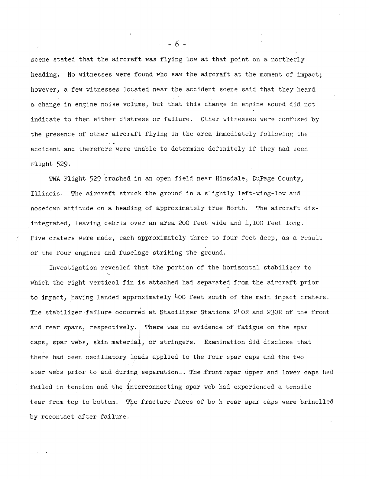
scene stated that the aircraft
was
flying low
at
that
point on
a
northerly
heading,
however,
a
few witnesses located near the accident scene said that they heard
No
witnesses were found who
saw
the aircraft
at
the moment of impact;
-
a
change in engine noise volune, but
that
this change in engine sound did not
indicate to them either distress
or
failure. Other witnesses were confused by
the presence of other aircraft flying in the area immediately following the
accident and therefore were unable to determine definitely
if
they had seen
.-
Flight 529.
TWA
Flight
529
crashed in an open field near Hinsdale, DuPage County,
Illinois.
The
aircraft struck the ground in
a
slightly left-wing-low and
nosedown attitude on
a
heading of approximately true North.
The aircraft dis-
integrated,
leaving debris over an area 200 feet wide and
1,100
feet
long.
Five craters were made, each approximately three to four feet deep,
as
a
result
of
the four engines and fuselage striking the ground.
Investigation revealed that the portion
of
the horizontal stabilizer to
which the right vertical fin
is
attached had separated from the aircraft prior
to
impact, having landed approximately
400
feet south
of
the main impact craters.
The stabilizer failure occurrdd
at
Stabilizer Stations 240R and 23OR of the front
and rear spars, respectively. There
was
no
evidence of fatigue on the spar
caps, spar webs, skin
material,
or
stringers, Examination did disclose that
i
I
there had been oscillatory loads applied to the four spar caps md the
two
spar webs prior
to
and during separation.. The $ront-.spar upper and lower caps
lied
failed in tension and the
4!
nterconnecting spar web had experienced
a
tensile
tear
from top to bottom.
The fracture faces of
to
11
rear
spar
caps were brinelled
by
recontact after failure.

-7-
There were several indications that the elevator
had
beer,
at
its
maximum
The most
significant evidence of
this
was
in the deformation
*
upward travel.
pattern impressed
in
the right rudder by
the
elevator outboard closing
ri.b
in
a
manner and position such
that
the
elevator
had
to be
full
up
at
the time
the
rignt
rildder
was
forced into
it
during
the
stabilizer separation.
The landing gear
was
determined to be in the
up
and locked position
at
impact.
Th.e
flaps and landing lights were retract.ed,
and
all
filght
controls
and
their
comterbalances
were
accounted for,
There
was
no evidence of in-flight
fire;
however, there
was
considerable
evidence of ground
fire
on
portions of the wreckage which
also
showed severe
impact damage
e
Exan5nation of
the
wreckage revealed no evidence of an in-flight explosion
or colllsim
with
foreign objects.
the
D(:
and
AC
units
was
found.
No
evidence of electrical overheating
of
Measurements
and
readings were
made
of
all
trim
actuators
and
their
asso-
ciated cockpit, position indicators.
The
variations of readings within each of
the
trim
systems prevented any determination of in-f1igh.t
trim
positions,
The
two aileron boost
assemblies
were found in the boost-off posit:on
as
was
the aileron boost cutoff valve,
was
found
in
the
boost-on position.
The shift handle in the cockpit, however,
0
Since
the
shlfting mechanisms are inter-
connwted
by
long lengths
of
cable subject to being pulled by fragmenting
structure fol.lowing impact, the position of the cockpit handle
is
considered
to be the more reliable,
but not positive, indication
of
aileron
boost
con-
dition.
Under
funct!onal testing,
the component, of
the
left. aileron boost,

-..
-8-
package functioned satisfactorily.
The right aileron
boost
pmkage
was
Loo
badly fire-damaged to be
tested.
-
-
The position
of
the rudder boost shift handle could not
be
determined,
but
all
affected components
of
the boost package
were
in
the
boost-on position.
The
components
of
the boost package functioned normally when tested,
The elevator boost shift handle
was
found
in
the on position
as
was
the
boost package,
to operate s&kisfactorily, commensurate with the Impact damage suffered by
the
unit, except for the disconnection
of
one
link
of
the psrsllelogram,
which
is
discussed below,
The
components
were
functionally tested individually and found
Examination
of
the parallelogram linkage
of
the
elevator
boost
located in
the
extreme
aft
section of the fuselage revealed
a
5/16th-inch
AN-175-21
nickel
steel
bolt to be missing.
<
(See
Appendix
A,
Fig.
1.
)
This parallelogram
linkage connects the pilot elevator input to the control valve of the elevator
boost system,
including sifting of
earth
in the wreckage area.
.
-
The
boTt
was
ndt found in the wreckage
despite
a
thorough search,
The
arm
assemblies,
part
No.
291089L,
part
No.
291089R3,
and link assembly,
part
No.
290790
(See Appendix
A,
Fig.
l),
were
examined to determine
if
the
bolt
was
in place
at
time
of
impact,
passes through the
press-fit
bushings
of
P/N
291089
arm
assemblies and the
P/N
290790
link assembly,
This
bolt,
when
in
its
proper position,
The
head
of
the bolt
is
installed against
the
outboard
face of
arm
assembly
P/N
291089~,
is
flush with the face of the forged
arm,
there
were
two deposits of old thick
grease having the consistency
of
modeling clay and
0.01
inch
or
more
deep.
On the outboard face of
the
bushing, which

-9-
(See Appendix
A,
Fig.
2,
)
arc
of
120
degrees from the
11:OO
tb
the
3:OO
o’clock positions,
3/32
inch in width.
The larger of the two gresse deposits covered an
and averaged
-
The inner edge
of
this dgposit
was
common
with
the
inner
circumference of the Sushing, whereas the outer edge
was,
in places.. slightly
beyond the bushing’s outer clrcmference;
however,
a
sl$,ght outllne
of
two
sides
of the bolt’s hex-head
was
visible around
its
oiter perinieter of the
deposit
I
-
(See Appendix
A,
Fig,
2,
)
The
smaller
deposit covered an arc of
60
degrees between the
7tOO
and
9:OO
o’clock positions
and,,
like
the larger deposit,
the
inner edge
was
commm
with the bushing’s inner circumference and
was
abodt
3/32
inch wide.
There were many scuff marks across the faces of both deposlts, but neither
had received any compressive loads
sufficient
to
Those pcytfons of the bushing which had no heavy
’
of grease of the same consistency,
After cleaning
-
the faces
of
the bushing,
it
brinelling and elongation.
KO
elongation of the
flatten their top surfaces,
grease buildup shcwed
a
film
was
examined for scratchez.,
bushing hole could be found,
On the bushing’s inboard face there
was
a
nick on the outer circanference
at
the
8:oo
o’clock position measuring
0.020
x
0,045
inch and
estizxated
to be
0,Ol
Inch deep,.
Three light longitudinal scratches could be seen in the bore of the bushing,
Also
present were light circumferential scratching and polishing,
P
but were not discernible when
it
was
cleaned,
At
the outbcard face
of
the
--
mTheock positions were. referenced by passing an imaginary line through
the centers
of
the torque tube hole and the hole
at
the actuator end, the latter
being in the direction
of
12:OO
o’clock,
Thereafter, clock references were used
as
the part
was
being viewed
at
the time,
were referenced by passing imaginary lines throu_.i their centers parailcl to
the
reference line
of
the part and with the
12:OO
o’cloclt and
6:oo
o’clock
ends con.,
si
stent therewith.
Subcrponents such
as
the buskings

-
10
-
-...
bushing,
surface scratches could be seen on the forging.
The edge of these
scratches
was
concentric with the circumference of the bushing and the approxi-
mate
diameter
of
an
AN-960-516
washer.
It
was
noted, however, that the edges
of the grease deposlts had overlapped portions of this scratched area,
than light concentric scratches, this face of the bushing showed
no
impact
marks, brinelling,
or
denting.
Other
On the inboard face of the
arm
assembly
P/N
291089~
at
and near the edge,
there
was
a
deep gouge made by the sharp corner
of
the clevis of the
P/N
290790
link assembly.
The face of this gouge
was
generally triangular, and the
maxi-
mum
depth
was
0.035
inch with definite chatter It.,arks across the gouge face,
Along two sides
of
the triangle the
edges
were
sawtoothed in shape, showing
some of the individual cycles
of
chatter.
of
the link would not line
up
with the
arm
assembly bushing when
the
clevis
was
aligned
with
any of the sawtooth points,
The
bolt
hole
at
the opposite end
'
The nut of
the
missing bolt
is
normally installed against the outboard
I
face
of
right
arm
assembly
P/N
291089R.
There
was
no deposit of grease on the
outboard face of the bushing of the right
arm,
nor
was
there on the surface of
this
arm
the heavy splatter of grease
and
dirt such
as
appeared on the
left
arm.
Some grease
was
present,
but
only
as
a
film.
was
unscarred except for slight concentric scratches. The outline of
a
washer
could be seen on the face
of
the forging, but sufficient pressure had not been
The outboard face of this bushing
applied to remove the zinc chromate.
The outboard one-third of the bushing's
bore
showed heavier corrosion than the other two-thirds and contained some
irregular scoring There
were
several threadlike score
marks
on
the
bore's

-
11
-
inboard one-third from
9:OO
through
3:OO
o'clock-
At
several places near the
12:OO
o'clock position these scorings
were
polished and flattened. The inboard
face
of
the bushing
wa8
clean
and
a
concentrlc impression
of
the
link bearirlg
was
visible, There
was
a
thin dreg mark
ai;
the bushing's inner clrcumfercnce
at
9:OO
o'clock,
0.005
inch wide
by
0,lO
inch long; parallel to the
arm
center-
line.
At
the outer circumference
of
the bushing's inboard face
at
the
1:OO
-
o'clock position there
was
a
curved brineil mark
0,125
inch long by
0.015
inch
wide.
When viewed under magnification, another brineXing cculd be seen
suprrimposed wlthin the
first
one. The curvature
of
these marks, oppGsite
in arc to the circumference of the bushing, exactly matched t'hat
of
the cir-
cular end of the
P/N
290790
link assembly.
The
flow
of
metal showed that both
brinellings had been formed in
a
direction
away
frm
the bushing center,
No
elongation of the bushing hole could
be
found,
-^a.
The
bolt
hole
of
link
assembly
P/N
290790,
which
is
the bearing inner
race, together with the bushings,
were
checked
for
roundness and found
tG
be
within tolerance.
me
bore
was
in excellent condition, although there
was
a
slight brine11 mark on
the
circular end of the link on the right side.
At
impact, the four powerplants broke loose from their
aft
structure and
their components
were
widely scattered in the wreckage
area.
The nose sections,
I
with propeller hub dome assemblies
still
attached,
were
found
a
few
feet
ahead
of each engine nacelle impact crater
settings and the propeller blade shim
plates
indicated that the propeller blades
of
each engine
were
set
a
an angle of from
29
to
30
degrees
at
the
time
of
im-
pact,
Tests
of
the propeller governor component.? from each engine revealed
a
range
of
ayproximately
2,450
to
2,525
r.p.mo
at
impact
I
Readings taken from the propeller dome
,
7
/

-
12
-
There
was
no evidence
of
any operational failure or malfunction of any
*
engine or propeller component,
-
-
N
86511
was
delivered to
TWA
in December
1945,
and had accumulated 43,112
hours
at
the time of
the
accident.
overhauls, there were two major repairs accomplished.
performed by the Lockheed Aircraft Corp. in the spring of
1951,
and the
air-
craft had accumulated approximately
33,000
hours since this repair. In
January
1958,
the center rudder
was
replaced because of bad fabric.
A
base
overhaul
was
accomplished
at
IWA'S
Kansas City Base in May
1959,
at
which time
there
was
a
routine replacement
of
the boost control units. The
last
base
overhaul
was
performed during November
1960,
at
which time an elevator boost
control replacement kit
was
installed.
assembly and,
therefore, the installation work required the removal and rein-
In addition to the routine major and base
The
last
repair
was
This kit included
a
parallelogram
stallation
of
several bolts, including the
AN-175-21
which connects the
P/N
290790 link assembly-ith the
lever
arms.
The
last
detailed controls inspection
was
made during the
last
scheduled periodic checks
on
August
7,
1961.
periodic checks included
a
visual inspection of the control components,
daily and turnaround inspections for August were accounted for.
These
All
Levels of carbon monoxide saturation in the tissue specimens
of
crew
0
members were found to be
less
than
10
percent, the accepted high
limit
of
normal; no alcohol
was
found.
Tissue
specimens of passengers revealed even lower levels
of
carbon
monoxide.

-
13
-
/Inalyci
s
-_IC
There
can be no doubt that the AN-175-21 bolt
was
Kissing frcn
tkc
pard-
lclogram
assembly when the elevator boost package
was
first
exs,ni:~ed,
'The
-
problem demanding solution can
be
stated
as
follows:
Was
the bolt extracted by impact forces,
or
vas
it
mis..
.
ing
from
its
installed location prior to the crash?
First, to discuss
the
possibility
of
the
belt
being
torr:
out
on
inpact,
the geometry of the system
is
such, and the resultant post-accident orients-
tion of the parts
was
such that there could
be
only
two
ways
to
remove
the
bolt:
(1)
in double shear by displacing the P/N
290790
link assenbly, acd
(2)
by tensile load caused by spreading the
P/N
2910895
and
R
amA
assemblies
against
the head and nut of
the
bolt.
The double shear possibility can easily
be
eliminated
There
was
nc
elongation
of
either arm assembly bushing; contra to elongation,
the bushings
were
out-of-round by
less
than
0.2
percent
The fact that the bolt
was
missing
is
further proof
that
it
was
not sheared,
since the
ductility of
the
.steel
bolt
and the bushings would allow sufficient deformatlon.before fractLre to
seize
the bolt sections
I
The only remaining method of bolt removal on impact would
be
to
place
it
in tension.
boit
or
removal of the nut by thread strippage
or
by splitting the nut.
a
shear nut
were
used,as
a
&A
witness testified, the thread strippage
would
The resulting failure would
be
either by tensile failure of the
I
If
l
be
the more likely possibility.
it
is
assumed that
a
shear nut
Mas
used in the installation and, thereby, the
following argument
is
conservative
Since
this
requires
the
lesser tensile force,
/

-
14
-
The failure loads of the bolt assembly units
are:
-
Load, lbs,
-
3/
.-
AN-175-21
bolt
-
yield
4,890
AN-175-21
bolt
-
ultimate
6,500
AN-320-5
nut
-
ultimate
3,250
AN
-3
80
-
2
-
2
e
0.t
t
er
key
-
ultimate
210
Since the cotter key failure load
is
low in comparison to the others,
its
additional strength to the system can
be
ignored without appreciably
altering the results
It
can
be
seen
that
the
nut would
fail
well before the
yield point
of
the bolt
is
reached; therefore, the load of concern here
is
3,250
pounds
-
Recalling that there were two heavy deposits of thick grease on
the
out-
board face of the left
arm
assembly,
it
is
now possible to calculate
the
pressure
which would be applied to the
surface of the deposit
if
the bolt assembly
be
placed in tension to the failure point.
The
geometry
of
the
boost package
assembly
is
such
that
the only way to place the bolt in tension
is
to
spread
the
two lever
arms
apart, either in bending one or the other outward or in translating
one of them away from
the
other.
left bushing into contact with the bolt head, or
it
clamps between
the
bushing
Either action places
the
outer face of the
aAd the bolt head any object (washer and/or grease) in this path
of
action.
If
the grease deposit originally covered
the
entire bushing surface,
as
it
probably
did,
the pressure
would
be
28,300
p.
8.
i.,
an enormous amount of
pressure
to
be withstood by
a
substance
with
the consistency of modeling clay.
Since the grease, under pressure, could be extrud
.i
radially throughout
360
-
3/
These are tensile loads
on
the assembly, l.e., tension on the bolt, shear
on
the nut threads, and double shear on the
cotter
key.

-
15
-
degrees,, both toward
alid
away from the bushing center: the fact that the
deposit
was
still
0.10
inch
or
more deep
is
proof sufficient
that
no such
pressure,
or
any appreciable fraction thereof
was
applied
-
Became of the geometry
and
dimensions of the
system, the gouges and
scratches referred to earlier could have been made only after the bolt
was
extracted, releasing
the
iink assembly,
marks on the inner
surface
of
the left
arm
could not have been made concur-
It
was
further noted
that
the chatter
-
rently
with
tte indentations on the bushings, nor could the indentations on
the
two bushings have been made simultaneously, There occurred
at
least four
individual actions,
three on the right bushing and one on the
left,
plus
the
multiple chatter marks shown on
the
arm
assembly
Indications are
that
at.
some earlier time the bolt may have moved
to
a
point where
its
end
was
about two-thirds into the bushing of the
right,
am
of
the lever assembly
This
would provide some protection to the two-thjrds of
the bore,
bult
expose
the outer one-third to the atmosphere, allowing
it
to
corrode, The thread
marks
at
:he
inner one-third of the bore further indicate
a
partially displaced bolt
portion
of
the bore
while
the bolt
was
in
a
normal
position.
The
thread impressions could not be made in this
In crder for grease or any other material to build
up
on
the
outer surface
0
of the left
arm
assembly bushing, there o%viously must be
a
gap between the
bushing
and
the bo.lt head (or washer)
I
this
gap but,, in
any
case, regardless of
initial
cause,
the
nut
must
be
loose
by
at
least the nmber of threads erpivalent to the maximum thlckness
of
the
There are probably many ways to cause
grease,
~/6b
inch

-
16
-
The heavy deposi+, and the splatter
in
the
vicir,:ty
of
the
lift
bushing
appeared
to
have come, in the main, from the bushing bcre, having
bcen
splattered
out
of'
th.2
bushing
by
the loose, chattering
belt
In
coning
wit
the
oil
or
greasp would have struck the bolt head
(or
wasker) and been deflected radially
That portion depositing
itself
between the bush2r.g and tkLe
bolt
head
(or
washer)
would Pave
been
packed down by motion
of
the bolt
The
fact
ttdt
nc
sAch
deposil
or
heavy splatter existed
at
the otter bushing would indic5te
that
-
._
durinG
'a
considerable period
of
time
the
nut
was
not in place, thus aLlowing
oil to eject from the bushing and
fall
free,
Prior
to
the
Civil Aeronautics Board public hewing there existed
a
question
of
how the grease deposit showed the hexagonal
outline
of
a
bolt head
when Lockheed Aircraft Corp. drawing
No
209835 calls
-?c.-
two washers, one
at
t,he head of the bolt and one
at
the nut
It
was
evident that
a
wssher
had been presen-i;
at
one
time
became one
had
left
its
impression on the
lever
am
and could be seen
after
the grease
w&s
cleancd
away.
If
the installation
were
made
according
to the
LAC
drawing, the hexagonal pattern could not have
been present since an
~~-960-.51G
washer
has
EL
greater dianetep than
tSe
mad
cf
an
AN-175
bolt.
This
apparent anomaly
was
cleared
at
the hearing wken
a
TWA
mechanic: testified that because of tolerance variations,
it
was
not always
pdssible to
secure
the nut
if
a
washer
is
installed under the kalt head
such
cases
the
washer
is
removed and the lnstallation
made
without It The
Board does not suggest
that
thio
is
an unsafe practice, but
it
does explain
how the shape of
a
bolt head could be scen in the grease pattern
Tt
is
clear
that
a
was!
L'r
was
used
at
this point
on
at
least
c
.e
previow
parallelogram
instailation, but not on the
one
installed in November
1960.
In

The
TWA
rx?cbd)?ic
further stated in
his
testimony that he installed the
repair-kt linkagr
rzt
the
Last
base
,wer'nail;
in November
1960
ke
also
said,
-
"I
am
sure
stJl
bciLs
weie
installed,
properiy
torqued>
arid
safetied
.
.
.
1'
,
.
but
sbksequently
adds?,
"1
do
nct
remem'cer
specifically working
ct!
Plane
555
Since
it
kas
been
stow
that
tke
AN-L75-21
Colt
was
missing
from
its
noma1 Ixatjcn
at
the
tine of
ixpact,
if
beconlrs
necessary
t3
discuss
the
effect
on
th2
aircraft
when
the
b6-t
is
X€EOwd.
Witq
reference
to
AppEcdLx
A;
Fig.
6,
it
can
be
seen
tkat
pilo+,
iripdt
moves link
BIZ
IC
or
down
which
pivots link
EDC;
as
a
walking
beam
&out
polnt
I?,
causing
pcint
E
tc
aove
dcwn
or
up.
This
pasitions
the
control
iraive
spool
which
is
L:--
?c'ced
at
pojrit
E,
ElEvatar
inp&
mwes
Link
AD
up
or
down which,
in
turn, p?:vct,s ilnk
ED2
&Gut
point
C.
This
action also
po6itior.s
the
control
valve
spooi.
I't
sho~'/;
be
Eoted
that
pilot
and
elevator inputs
in
the
same
direczicn
art,
s~btractlv~
ar,d
inputs
in
opposite
dllections
are
additive
to
the
vs-ve
spc:cL.
I
If
the
AN-175-21
bolt
at
poxt
A
ke
removed,
no
support
for
the
paral-
leiogrm
is
prrjvlded
by
,Snk
AD,
and
Ilnk
EDC:
is
free
to
pixyot
abo.;t,
point
C
Since
tl-e
vsive
is
rmuntc.d
In
8
near-vertical positicr.,
tke
v;ig%t
of
licks
AQ
and
EIX:
and the
wiight
of
the
spoctl
are
applied
in
the
direction
to
move
the spoci tpward
~p-~.Ie~~atnr
to
be
res;sted
only
by
the friction in
the
vaivc
and
at
pcicts
(l
and
F.
th?
t02a.1
of
whicl-
is
regligikie.
Any
frlction above

-
18
-
As
soon
as
the
valve
spoc3
ports
fluid
to the
up-FtLevstor
side
of
the
actuator,
thc-
elevatx
will
start
to, move up, positive normal acceleration
is
applied tc,
-<k,e
aircre.ft wbich
will
drive
the
spool
lower; more
up-pievator
-
pressure?
rricr~
accel~ration.
It
may therefore be seen
that
the entire operation
from bolt
extractior,
to maximum up-elevator hinge moment.
is
airnost instanta-
neous
Furthm
reference
to
the sketch shows that there can
be
no p?.,ot. input
to %h? vai\rt
to
ccw-teract
tke
action since
the
parailelogwn can no
longer
pivot
at
point
D.
InpfJt applied by the pilot
is
only
carried throLgh
the
mechanical
linkage,
The mechanical aduantage
of
the systen
is
far
too
low
to
be
effective agsirst
C,he
full
pressure in
the
bocst actwtoy
hn a
stLdy
-
5/
of
the Consteiiation
toost
systems,
it
was
pointed
out
t\at
the
systems
will
develop appsoximsteLy
8,:
times more hinge moment with boost
on
than
with
boost off,
This
factor
is
even greater
with
the above-.described malfunction
because the
pllct
does not have
the
added mechanical advantage
gained
by
shifting to manml position.
The
only 2ffective pilot action
is
to
shift
the
elevator
systen:
to manual
This
shift
acccmplishes three thlngs:
I*
Closes
the
boost. ,cut.-off valve;
,
2.
Opens
the
bypss
valve
at
the actuator; and,
3.
Changes
tke
mechanical advaritage
of
the direct pilot-to-elevator

-
19
-
Therefore,
it
would appear that recovery from such
a
malfunction would
be a simple, straightforward operatidn.
which can introduce
a
severe problem. That function of the shift-to-A.ianual
There
is
a
peculiarity
of
the system
-
operation which changes the mechanical advantage of the system has the effect
of lengthening the connecting system between the control columm and the elevator
torque arm. That
is,
the portion of mechanical linkage upstream
of
the shift-
ing area (dual link rod) tends to move the control wheel aft, and that; portion
downstream tends
tr3
move the elevator downward.
If
the two hydraulic valves
had operated PrcFerly,
and there
was
no evidence in this case that they would
not have, t.he elevator would have been
free
to move downward
assisted
by
air-
load hinge moment; however,
if
there had been no forward pressure on the con-
trol column, the column would have been free to move
aft,
and the shift to
manual could have been completed.
If,
however, the crew had applied forward
pressure on the column while trying to shift, the shift would have become
increasingly difficult
in direct ratio to the
amount,
of
forward pressure.
The elevator has boost-on
limits
of
40
degrees up and
20
degrees down,
but
is
further limited with increasing airspeed by boost hinge-moment maximum
of
49,000
to
5h,OOO
inch-pounds.
is
reduced to
16
degrees
'up
and
6
degrees down because of the increase in
In the manual position, elevator deflection
mechanical advantage, Therefore,
if
shift to manual
is
started when
the
elevator
is
up more than
16
degrees,
it
must be
at
or
less than
16
degrees
bergre
t.he
shift can be completed.

-
20
-
From this description
of
the system
it
can be seen that
if
the pilot re-
sponds normally to
a
stall,
the following describes the events irhich
will
occur when the
M-175-21
bolt works out of the-parallelogram:
-
1.
When the bolt comes out, the weight of the
spool
and two of the
parallelogram links cause full pressure to be applied to the
up-
elevator side of the actuator,
-
2.
The elevator travels up to
its
maximum hinge-moment For the
speed
at
which this aircraft
was
assumed to
3e
operating,
this
would be less than
40
but greater than
16
degrees.
3.
The aircraft enters an accelerated
stall,
As
this
stall
decays
toward
a
primary
stall,
the elevator angle increases to
40
degrees.
The captain
or
first
officer,
or
both, would normally apply high
,
_I.
4.
forward pressure on the control
column
in an attempt to get the
nose down,
5.
While this forward
pressure
is
being applied, the
crew
attempts
to
-
pull
the shift handie.
With the elevator
at
its
maximum
deflection
(maxim&
hinge-moment
6.
or
40
degrees, depending on speed) and held there by full hydraulic
pressure and with forward (nose-down) force on the column,
it
be-
.
comes difficult,
if
not impossible, to move the
shift
handle
far
enough to operate the
shLtoff
ond/or
the
bypass
valves.
7.
With
the
aircraft
sidled,
or
executing
a
series
02
stalls,
even
though altitude
is
being
lost,
the
nose
must be lowered
to
effect
recovery; hence, increased forward force
,-esults
in
a
higher force
required to
pull
th.e
shift handle.

-
21
-
..
..
..
--
/
8,
Accelerated
stall
vibrations may cause .empennage
or
rear fuse'lage
damage.
It
will
be shown later how accelerated
stall
is
the
known result of bolt extraction, a6d structural damage
is
a
possible result
of
accelerated
stall.
There can be
no
doubt
in
the subject case that the elevator
was
at
the
40-degree up position
at
some point during the empennage
failure.
The right
outboard closing
rib-was
crushed by,
and left
its
impression on, the fin and
rudder.
Matching the parts showed clearly the 40-degree elevator position.
Following several accidents involving Navy
R7V
and
Air
Force
C-12i
air-
craft
(1049
models), the
Air
Force contracted with Ling-Temco to conduct an
analysis
of
the Constellation elevator
system.
The Temco report indicates
that when the shifting system
was
tested
on
a
mock-up with simulated airloads,
shift operation could not always be completed when
100
or more pounds
of
stick
force
was
applied, or,
if
completed,
it
was
done
with high pull forces on the
shift handle.
Following the
fatal
accident of
a
Navy
R7V
at
Taft,
California, on May
14,
1958,
Lockheed Aircraft Corp,
conducted
similar
tests
and issued
LAC
Report
13142
not be accomplished
if
it
is
resisted by large control forces.
This
report shows that with extreme elevator deflections, shifting can-
The report
states,
in
part:
"A
study of the curves
reveals
the marked effect
of
colunn forces
on
shift force, but also that there
is
a
reasonable amount of column
force allowable,"
The
report continues: "The conditions permitting
a
shift to manual have considerable latitude,. tepending upon surface
1
I
/

-
22
-
moment,, restraining column force, and surface angle. Within these
limits
many opportunities would be present permitting
a
shift
to
manual position.
-
I!
6/
.-
The
Board
believes
that
opportunities-within-limits
is
a
questionable
approach to the design philosophy of an emergency system.
When controls are
jammed,
particularly in
an
unxianageakle
regfme,
and
if
a
corrective mechanism
is
available,
a
pilot shou.ld
be
offered
a
positive correction, not opportuni-
t
i
e
s
-wl
t
hin
-limit,
s
As
far
as
is
'known
them
tave
been
no
previous
similar
problems with the
elevator boost system in the civil operation
of
Constellations; however, the
military services have had
an
accident and an incident involving Constella-
tions, the causes
of
which
were
attributed
to
similar
elevator boost malfunctions
and the inability
to
shift
to
manual,
The
accident
was
the
Taft
case,
referred
to
above.
It
was
determined
that
clevis bolt
to the valve
spool
(Point
E
ir,
Appendix
A,
Fig,
6)
backed
out,
separating the
P/N
LS-508-4-20,
which connects the parallelogram linkage
-
spool
from the linkage,
While
this
2s
not the same bolt
as
in the instant
I
case,
the effect
is
shilar;
tne
spool
is
free to move in either direction,
but
its
natural tendency wculd be down (elevator
up).
within-limits
should seriausly consider the following facts regarding this
I
Advocates
of
opporbjnlties-
I
I
accident
:
/'
1
1.
The aircraft
was
observed
by
many witnesses to execute several
360-
degree
turns
dcrir,g which the aircraft pitched
up
several times,
/
zmerscoring
supplied
/
/

-
23
-
-.-
but;
never regaining
all
lost altitude. The
general
consensus
was
that wheu the nose pitched
down,
the wings were momentarily
leveled
or
nearly leveled, followedby
a
pitchup and break to the
I
Left to steep bank angles.
. .
2.
Despite
the
fact
that
the aircraft descended in
this
manner
from
13,000
feet,
12,300
above accident
site,
thus allowing several
minutes for-corrective action, the elevator boost system
was
stili
in the boost-on position
at
impact.
3.
The
crew
was
far
from Inexperienced$ The record shows:
Crew
Member
Total Time
R7V
Time
Aircraft Commander
5674
1233
Copilot
4404
342
1st
Flight Engineer
----
2088
2nd Flight Engineer
--
--
1052
4,
In an apparent last-ditch effort to get nose-down pitching moment,
the crew selected
80
to
100
percent flap.
,
The incfdent,&he details of which were entered in the record
at
the
public hearing,
also
involvea
an
R7V.
While the initial’malfunction
was
of
a
completely different nature, the result
was
the
same.
separated actuator piston ported the valve
;to
the full elevator-up position.
The weight
of
the
The aircraft executed five successive accelerated
stalls
and lost
3,000
feet
of
altitude before the system could be deboosted.
vibrations caused serious structural damage to skin, stringers, and bulkheads
The
forces and accompanying
in the
aft;
.portions
of
the fuselage
Further
proof
that
accelerated
stall
can produce structural failure
is
During
one flight,
found in
the
records of
R7V
structural integrity cests.

-
24
-
...-
the aircraft
was
inadvertently put
into
an
accelerated
stall.
Inspection
following the incident revealed that there
w_as
a
complete
separation
of
the
right stabilizer
rear
spar
web,
This separation
was
located one-half
a
rib
station inbosrd
of
thy point
a+,
which
the rear spar failure
of
N
86511
occurred.
Conclusions
The Board has attempted tc
stow
in this report how the physical evidence
-
proves that the
AN--175-21
boLt
:r,
the
psrallePcgram
was
missing
at
the time
of
iinpsct
and further to
prove
that the loss
of
the bolt preCiFitated the
accfdent,
The
effect
of
suh
less
kiss
keen explained and related to other
accidents and incidents.
It
has
also
been
shown how the accelerated
stall
resulting from bolt
loss
can
produce
stxctwal
failare
similar
to
that
of
the
TWA
aircraft.
me
Board conclades from
the
evidence
at
hand that
during
the clhbout
from
Midway Airport, the
AN-175-21
bolt
worked
its
way
clear
of
the pai*all--.io-
gram
link,
This
wasfollowed immediately by
full
pressure
to
the
up-elevator
side
of
the actuator pls%on.
The
p-i.lot’s
natural response to the resulting
violent pitchhp and acc:el.erated
stall
prevented successful shift
of
the
elevatcr
boost system
tc
the
manual
positToo,
The
manner in which the boit,
was
13st
is
largely
a
matter
of
conjecture,
,
There are many pcssibi1:t:es
The
cut ccrxSd have been left
off
at
the time
of installation
in
November
.196O;
howe-cer,
t?xh
is
nct prcbLble in view
of
the
length
of
time
which
elapsed
from
Kwenher
1960
until the occurrence
of
thc
accident.
The
shear
nLt
coc?=d
have
beer,
mer-tightened, thereby stripping the
threads, but
the
loads on the
FoLt,
are
such
that
€den
a
stripped
nut,,
if
it

-
25
-
has
a
cotter key installed,, could hold the bolt in place.
The most probable
reason, although
it
cannot be substantiated,
is
that the cotter key
was
omitted
at
the
timc-
or
the parallelogram installation and that during the intervening
-
.'
months
':<,I
nut backed off and allowed the bolt to come out. The immediate
valve,poYting, the rapid onset
of
hydraulic pressure to the boost actuator,
and the res1Jlting
maximm
hinge mment' on the elevator associated
with
loss
of
this
bolt prove
conclusively
that
the
loss
could not have
occurred
prior
to
the
climbout
from
Midway Airport,
On Noverr;ber
22,"
2.961,
the Board recommended
tc
the Administrator
of
the
Federal Aviazion Agency that the mechanism for shift-to-manual
in
the Con-
'.
stellation control boost system be modified
so
that the actions would be
sequential
rather
than simu2taneous. Specifically, under the recommended
change,
the
shifting action by the pil&
would
remain one continuous motion
of
a
hand2e but would,
first,
open the
bypass
valve; second, close
the
hydraulic shutoff valve and, third, shift the mechanical linkage. With such
an asrangeKent,
all
hydrau1i.c pressure in the boost package
would
be relieved
prior
to
the
mechanical
shift action and
would
thus allow the complete shtft-
-
to-manual without restriction regardless of pilot-applied control fcsces,
On March
8,
1962,
the AdmMstsator advised the Board that his Agency
was
having
the
ConsteLlation
Flight
Manual amended
to
include "procedures
for turning off the
elevator
't3ocst.
with
an
uncontrollable elevator." The
Administrat.or hrther advised that "in view of the excellent service
hl
stlory
achieved
by
this
aircraft since certification in
1946,
we believe
there
is
insufficient justification to require dpsigr,
ch&rIJ
2s
to
[email protected] yoLr
tot81
objective."

-
26
-
Although turning off the elevator boost provides'
a
possible means of
regaining control,
it
appears hopeful to
assume
that
a
piiot
will
recall
-
and execute successfully the flight manual inst-ructions when confronted
un-
expectedly with
a
violent structrire-damaging maneuver instinctively resisted
by pushing on the control wheel,
August
2L9
1962,
that further consideration be given to modification
of
the
shifting system
The Board, therefore, recommended on
-
Probable Cause
The Board determines that the probable cause of
this
accident
was
the
loss
of an
AN-175-21
nickel steel bolt from the parallelogram linkage of the
elevator boost system,
resulting
in
loss
of
control
of
the aircraft.
BY
THE
CIVIL
AERONATPTICS
BOARD:
/s/
ALAN
S.
BOYD
Cha
i
rma
n
Is/
-
ROBERT
T,
MURPHY
Vice
Chairman
181
CHAN
GURNEY
Member
/SI
Ga
JOSEPH
MINETTI
Member
/SI
WHITNEY
GILLILLAND
--
Kember

Investigation
and
Hearing
a
The
Civil Aeronautics Board
was
notified
of
this accident on September
1,
1961.
An
investigation
was
immediately initiated in accordance with the
provisions of Title
VI1
of
the Federal Aviation Act of
1958.
A
public hearing
was
ordered by
the
Civil Aeronautics Board and held in
the
Charles Continental
House, Midway Hotel, Chicago, Illinois, on September
27,
1961.
Flight Personnel
Captain James
H'
Sanders, age
40,
was
employed by Trans World Airlines
August
30,
1945,
and
was
promoted
to
captain June
18,
1954.
He
had
a
total
flying time of
17,011
hours,
of
which 12,633 were in Constellation equipment,
His
)total instrument time
was
3,242:30 hours.
Captain Sanders
held
a
FAA
certificate and
a
currently effective airline transport rating
No.
257341 issued
June
10,
1954,
on Douglas
E-3,
Martin 202-404; and Lockheed Constellation.
The
date
of
his
last
physical
was
June
26,
1961,
with
no
waivers.
He
had
a
rest
period
of
19
hours prior to subject flight.
His
last
proficiency check
was
June
17,
1961,
in
a
Lockheed Constellation and his
last
line check
was
on
May 20,
1961.
The
date
of his
last
emergency equipment review
was
June
16,
1961,
First Officer Dale Terrant,
age
31,
was
employed by Trans World Airlines
DFcember
5,
1955.
His
total flying time
was
5,344:43
hours, of which
1,975
were
in Constellation equipment.
hours.
Mr.
Tarrant had
a
total instrument time of
340
His
rest
period prior to subject flight
was
19:14
hours.
He
held
a
currently effective
FAA
certificate
with
commercial license
No.
1323998.
His
instrument rating
was
issued March
16,
1956
class physical
was
October
21,
1960,
with
no
waivers.
Thp
date
of
his
last
FAA
second-
His
rest
period prior to
-i-

subject flight
was
19
hours.
His
last
proficiency check
was
May
17,
1961,
in Lockheed Constel.lation eyuipinent,
ment
review
was
May
17,
1961.
The date of
his
last
emergency equip-
*
-
Flight Engineer
James
C.
Newlin, age
38,
'was
employed by
TWA
May
21,
1951.
He
was
promoted to flight engineer November
16,
1953.
His
total flying
time
was
5,816:54 hours in Constellation equipment.
to
subject flight
was
19:14
hours.
No.
1210446
issued
May
1,
1951,
and
FAA
flight
engineer certificate
No.
1282233
was
issued April
9,
1954.
The date of his
last
physical exsmination
was
December
30,
1960,
with no
Class
I1
waiver.
His
last
proficiency check
dated March
29,
1961,
was
in
a
Lockheed Constellation flight simulator,
Engineer Newlin's
last
line check
was
April
9,
1961,
and
the
date
of
his
checkout
on Constellation equipment
was
April
12,
1954.
Rest
Lleriod
24
hours prior
Mr.
Newlin held
FAA
AeGE
certificate
Flight
His
last
emergency
equipment review
was
March
29,
1961
The two
stewardesses
were
Barbara Jane Pearson and Nanette
G.
Fidger.
Both
had
complied with
all
company requirements with respect to training.
I
-
ii
-

APPENDIX
A
FIG.
1.
Elevator boost package. Bushing where
bolt should have been is indicated
by
arrow
“A”.
‘P
.
FIG.
2.
Close-up view before disassembly
of
bushing against which head
of
bolt should
have been.

APPENDIX
A
FIG.
3.
Close-up view of bushing
in
Fig.
2,
after disassembly but prior to cleaning.
FIG.
4.
Close-up of bushing against which nut
should have been. Taken after disassembly, but
before cleaning.

t
IfIdNI
IOlld
13
V
XlaN3ddV
