
Uncontained Engine Failure and Subsequent Fire
American Airlines Flight 383
Boeing 767-323, N345AN
Chicago, Illinois
October 28, 2016
Accident Report
NTSB/AAR-18/01
PB2018-100344
National
Transportation
Safety Board

NTSB/AAR-18/01
PB2018-100344
Notation 57292
Adopted January 30, 2018
Aircraft Accident Report
Uncontained Engine Failure and Subsequent Fire
American Airlines Flight 383
Boeing 767-323, N345AN
Chicago, Illinois
October 28, 2016
National
Transportation
Safety Board
490 L’Enfant Plaza, SW
Washington, DC 20594

National Transportation Safety Board. 2018. Uncontained Engine Failure and Subsequent Fire,
American Airlines Flight 383, Boeing 767-323, N345AN, Chicago, Illinois, October 28, 2016.
NTSB/AAR-18/01. Washington, DC.
Abstract: This report discusses the October 28, 2016, accident involving American Airlines flight 383, a
Boeing 767-323, which experienced an uncontained failure of the right engine and subsequent fire during
its takeoff ground roll at Chicago O’Hare International Airport, Chicago, Illinois. Of the 2 flight
crewmembers, 7 flight attendants, and 161 passengers on board, 1 passenger received a serious injury and
1 flight attendant and 19 passengers received minor injuries during the emergency evacuation. The airplane
was substantially damaged from the fire. Safety issues identified in this report include the lack of recent
guidance comparing production inspection processes for nickel alloy engine components, the need for
improved in-service inspection techniques for critical rotating parts of all engines, the lack of recent
guidance about design precautions to minimize hazards resulting from uncontained engine failures, the need
for separate engine fire checklist procedures for ground operations and in-flight operations, the need for
improved flight attendant training regarding assessing exits for evacuations and using interphone systems
during emergencies, the need for research on the effects of evacuating with carry-on baggage, and the need
for improved communication between flight and cabin crews during emergency situations, including
evacuations. As a result of this investigation, the National Transportation Safety Board makes seven safety
recommendations to the Federal Aviation Administration and one recommendation each to Boeing and
American Airlines.
The National Transportation Safety Board (NTSB) is an independent federal agency dedicated to promoting aviation,
railroad, highway, marine, and pipeline safety. Established in 1967, the agency is mandated by Congress through the
Independent Safety Board Act of 1974 to investigate transportation accidents, determine the probable causes of the
accidents, issue safety recommendations, study transportation safety issues, and evaluate the safety effectiveness of
government agencies involved in transportation. The NTSB makes public its actions and decisions through accident
reports, safety studies, special investigation reports, safety recommendations, and statistical reviews.
The NTSB does not assign fault or blame for an accident or incident; rather, as specified by NTSB regulation,
“accident/incident investigations are fact-finding proceedings with no formal issues and no adverse parties … and are
not conducted for the purpose of determining the rights or liabilities of any person.” 49 C.F.R. § 831.4. Assignment
of fault or legal liability is not relevant to the NTSB’s statutory mission to improve transportation safety by
investigating accidents and incidents and issuing safety recommendations. In addition, statutory language prohibits
the admission into evidence or use of any part of an NTSB report related to an accident in a civil action for damages
resulting from a matter mentioned in the report. 49 U.S.C. § 1154(b).
For more detailed background information on this report, visit http://www.ntsb.gov/investigations/dms.html and
search for NTSB accident ID DCA17FA021 Recent publications are available in their entirety on the Internet at
http://www.ntsb.gov. Other information about available publications also may be obtained from the website or by
contacting:
National Transportation Safety Board
Records Management Division, CIO-40
490 L’Enfant Plaza, SW
Washington, DC 20594
(800) 877-6799 or (202) 314-6551
NTSB publications may be purchased from the National Technical Information Service. To purchase this publication,
order product number PB2018-100344 from:
National Technical Information Service
5301 Shawnee Rd.
Alexandria, VA 22312
(800) 553-6847 or (703) 605-6000
http://www.ntis.gov/
NTSB Aircraft Accident Report
i
Contents
Figures ........................................................................................................................................... iii
Tables ............................................................................................................................................ iv
Abbreviations .................................................................................................................................v
Executive Summary .................................................................................................................... vii
1. Factual Information ...................................................................................................................1
1.1 History of Flight .........................................................................................................................1
1.2 Personnel Information ................................................................................................................4
1.2.1 The Captain ......................................................................................................................4
1.2.2 The First Officer ..............................................................................................................6
1.2.3 The Flight Attendants ......................................................................................................7
1.3 Airplane and Engine Information ..............................................................................................7
1.3.1 High-Pressure Turbine Stage 2 Disk Manufacturing Process .........................................8
1.3.1.1 Triple-Melt Process ............................................................................................9
1.3.1.2 Ultrasonic Inspection Process ..........................................................................11
1.3.1.3 Manufacture History of Accident HPT Stage 2 Disk ......................................13
1.3.2 Accident Engine Maintenance Events ...........................................................................14
1.3.3 Postaccident Engine Observations .................................................................................15
1.3.4 Metallurgical Examinations ...........................................................................................18
1.4 Tests and Research ...................................................................................................................22
1.4.1 Number of Flight Cycles in Low-Cycle Fatigue Regions .............................................22
1.4.2 Ultrasonic Response Characteristics of Discrete Dirty White Spots .............................23
1.5 Survival Aspects ......................................................................................................................24
1.5.1 Interphone Communication System ..............................................................................24
1.5.2 Evacuation .....................................................................................................................27
1.6 Organizational Information ......................................................................................................30
1.6.1 American Airlines Flight Crew Manuals .......................................................................30
1.6.1.1 Engine Fire Checklist .......................................................................................30
1.6.1.2 Evacuation Guidance .......................................................................................31
1.6.1.3 Evacuation Checklist .......................................................................................33
1.6.1.4 Evacuation Duties ............................................................................................34
1.6.2 American Airlines Flight Attendant Manual .................................................................35
1.6.3 American Airlines Training ...........................................................................................36
1.6.3.1 Flight Crew Training........................................................................................36
1.6.3.2 Flight Attendant Training ................................................................................37
1.6.4 American Airlines Operating Manual—Engine Fire Warning System .........................37
1.6.5 Boeing ............................................................................................................................38
1.6.6 Federal Aviation Administration ...................................................................................39
1.6.6.1 Advisory Circular 20-128 ................................................................................39
1.6.6.2 Inspection Techniques for Nickel Billets .........................................................41
NTSB Aircraft Accident Report
ii
1.6.6.3 Definition of Stealth Anomalies ......................................................................41
1.6.6.4 Notice of Proposed Rulemaking ......................................................................42
1.7 Additional Information ............................................................................................................43
1.7.1 Discrete White Spot Formation .....................................................................................43
1.7.2 Master Heat FA94 ..........................................................................................................43
1.7.3 Previous Related Safety Recommendations ..................................................................44
1.7.3.1 Recommendations From United Airlines Flight 232 Accident .......................44
1.7.3.2 Communication and Coordination Among Flight and Cabin Crews ...............46
1.7.3.3 Retrieval of Carry-On Baggage .......................................................................48
2. Analysis .....................................................................................................................................50
2.1 Accident Sequence ...................................................................................................................50
2.2 Checklist Issues ........................................................................................................................52
2.2.1 Decision to Perform Engine Fire Checklist ...................................................................52
2.2.2 Engine Fire Checklist Design ........................................................................................53
2.3 Evacuation Issues .....................................................................................................................55
2.3.1 Evacuation Sequence .....................................................................................................55
2.3.2 Flight and Cabin Crew Communication ........................................................................57
2.3.2.1 Interphone Issues .............................................................................................59
2.3.2.2 Recurring Evacuation-Related Issues ..............................................................61
2.3.3 Flight and Cabin Crew Evacuation Duties ....................................................................64
2.3.4 Carry-On Baggage Issue ................................................................................................65
2.4 High-Pressure Turbine Stage 2 Disk Failure ...........................................................................66
2.4.1 Discrete Dirty White Spot Detection During Manufacturing ........................................67
2.4.2 American Airlines Inspection of High-Pressure Turbine Stage 2 Disk .........................69
2.4.3 Guidance on Design Precautions to Minimize Rotor Burst Hazards ............................71
3. Conclusions ...............................................................................................................................75
3.1 Findings....................................................................................................................................75
3.2 Probable Cause.........................................................................................................................76
4. Recommendations ....................................................................................................................77
4.1 New Recommendations ...........................................................................................................77
4.2 Previously Issued Recommendations Reiterated in This Report .............................................78
4.3 Previously Issued Recommendation Classified in This Report ...............................................78
5. Appendixes................................................................................................................................80
Appendix A: Investigation .............................................................................................................80
Appendix B: Cockpit Voice Recorder Transcript ..........................................................................81
References .....................................................................................................................................90
NTSB Aircraft Accident Report
iii
Figures
Figure 1. Right side of airplane after uncontained engine failure and subsequent fire. ................ 4
Figure 2. HPT rotor. ...................................................................................................................... 8
Figure 3. Vacuum arc remelting process. ................................................................................... 11
Figure 4. Longitudinal wave scan used during ultrasonic inspections. ...................................... 12
Figure 5. Main fragments of the HPT stage 2 disk (forward side). ............................................ 16
Figure 6. Disk fragment locations. .............................................................................................. 17
Figure 7. Holes located forward and aft of the right wing front spar. ........................................ 17
Figure 8. Engine cross-section and fracture origin location. ...................................................... 19
Figure 9. Fracture surface from disk fragment A........................................................................ 19
Figure 10. Discrete dirty white spot in fracture surface. ............................................................. 21
Figure 11. Stringer in material microstructure. ........................................................................... 21
Figure 12. Fatigue cracks that initiated from discrete dirty white spot. ...................................... 22
Figure 13. N345AN configuration. ............................................................................................. 24
Figure 14a. Classic model interphone......................................................................................... 25
Figure 14b. New model interphone. ........................................................................................... 26
Figure 15. Engine fire handles. ................................................................................................... 31
NTSB Aircraft Accident Report
iv
Tables
Table 1. Flight attendant position, initial new hire date, and last recurrent training date. ............ 7
Table 2. Evacuation events shown on videos of left side of airplane. ........................................ 27
Table 3. Summaries of flight attendant evacuation actions. ....................................................... 28
NTSB Aircraft Accident Report
v
Abbreviations
AAIB Air Accidents Investigation Branch
AC advisory circular
AD airworthiness directive
AIA Aerospace Industries Association
APU auxiliary power unit
ARAC aviation rulemaking advisory committee
ARFF aircraft rescue and firefighting
ATC air traffic control
ATI SM ATI Specialty Materials
ATSB Australian Transportation Safety Board
BOS General Edward Lawrence Logan International Airport
CFR
Code of Federal Regulations
CLT Charlotte/Douglas International Airport
CRM crew resource management
CVR cockpit voice recorder
ECI eddy current inspection
EDT eastern daylight time
EICAS engine indicating and crew alerting system
ESN engine serial number
FAA Federal Aviation Administration
FDR flight data recorder
FPI fluorescent penetrant inspection
GE General Electric
HPT high-pressure turbine
JFK John F. Kennedy International Airport
MIA Miami International Airport
MTU Motoren- und Turbinen-Union GmbH
NPRM notice of proposed rulemaking
NTSB National Transportation Safety Board
ORD Chicago O’Hare International Airport
NTSB Aircraft Accident Report
vi
PA public address [system]
POI principal operations inspector
QRH quick reference handbook
RTO rejected takeoff
SAFO safety alert for operators
SB service bulletin
SEM scanning electron microscope
TWA Trans World Airlines
UPS United Parcel Service
V
1
takeoff decision speed
NTSB Aircraft Accident Report
vii
Executive Summary
On October 28, 2016, about 1432 central daylight time, American Airlines flight 383, a
Boeing 767-323, N345AN, had started its takeoff ground roll at Chicago O’Hare International
Airport, Chicago, Illinois, when an uncontained engine failure in the right engine and subsequent
fire occurred. The flight crew aborted the takeoff and stopped the airplane on the runway, and the
flight attendants initiated an emergency evacuation. Of the 2 flight crewmembers, 7 flight
attendants, and 161 passengers on board, 1 passenger received a serious injury and
1 flight attendant and 19 passengers received minor injuries during the evacuation. The airplane
was substantially damaged from the fire. The airplane was operating under the provisions of
14 Code of Federal Regulations Part 121. Visual meteorological conditions prevailed at the time
of the accident.
The uncontained engine failure resulted from a high-pressure turbine (HPT) stage 2 disk
rupture. The HPT stage 2 disk initially separated into two fragments. One fragment penetrated
through the inboard section of the right wing, severed the main engine fuel feed line, breached the
fuel tank, traveled up and over the fuselage, and landed about 2,935 ft away. The other fragment
exited outboard of the right engine, impacting the runway and fracturing into three pieces.
Examination of the fracture surfaces in the forward bore region of the HPT stage 2 disk
revealed the presence of dark gray subsurface material discontinuities with multiple cracks
initiating along the edges of the discontinuities. The multiple cracks exhibited characteristics that
were consistent with low-cycle fatigue. (In airplane engines, low-cycle fatigue cracks grow in
single distinct increments during each flight.) Examination of the material also revealed a discrete
region underneath the largest discontinuity that appeared white compared with the surrounding
material. Interspersed within this region were stringers (microscopic-sized oxide particles) referred
to collectively as a “discrete dirty white spot.” The National Transportation Safety Board’s
(NTSB) investigation found that the discrete dirty white spot was most likely not detectable during
production inspections and subsequent in-service inspections using the procedures in place.
The NTSB’s investigation also found that the evacuation of the airplane occurred initially
with one engine still operating. In accordance with company procedures and training, the flight
crew performed memory items on the engine fire checklist, one of which instructed the crew to
shut down the engine on the affected side (in this case, the right side). The captain did not perform
the remaining steps of the engine fire checklist (which applied only to airplanes that were in flight)
and instead called for the evacuation checklist. The left engine was shut down as part of that
checklist. However, the flight attendants had already initiated the evacuation, in accordance with
their authority to do so in a life-threatening situation, due to the severity of the fire on the right
side of the airplane.
The NTSB identified the following safety issues as a result of this accident investigation:
• Lack of recent guidance comparing production inspection processes for nickel alloy
engine components. The HPT stage 2 disk was made of a nickel-based alloy. Ultrasonic
inspections are typically performed during the manufacture of nickel alloy engine
components to detect internal defects (such as cracks and voids) in the material. However,
NTSB Aircraft Accident Report
viii
the discrete dirty white spot, which is consistent with the description of a “stealth” anomaly
in a 2008 Federal Aviation Administration (FAA) report on turbine rotor material design,
was most likely not detectable by the ultrasonic inspection methods used during production
of the HPT stage 2 disk. A 2005 FAA report that presented the results of industry’s research
about nickel billet inspections found that enhanced ultrasonic inspection techniques, such
as multizone and phased array inspections, could better detect internal defects than
conventional ultrasonic inspection techniques. The report also stated that multizone
inspection techniques were being used for titanium engine parts but that conventional
ultrasonic inspection techniques were still being used for nickel engine parts during
manufacturing. Additional FAA and industry efforts are needed to evaluate the
appropriateness of current and enhanced inspection technologies for nickel engine parts.
Updated FAA guidance describing the results of such evaluations would benefit those
involved with the inspection process for nickel alloy rotating engine components.
• Need for improved in-service inspection techniques for critical rotating parts of all
engines. In January 2011, American Airlines performed maintenance—an eddy current
inspection (ECI) and a fluorescent penetrant inspection (FPI)—of the forward bore region
of the HPT stage 2 disk with no anomalies found. (American Airlines did not have another
opportunity to inspect the disk before the accident because no engine maintenance between
January 2011 and the time of the accident involved disassembling the HPT stage 2 disk.)
These inspection techniques were not capable of detecting the cracks that emanated from
the discrete dirty white spot (a subsurface anomaly) because they could only detect cracks
and other anomalies at the surface (FPI) and near the surface (ECI) of a material.
Although ultrasonic inspections might be limited in their capability to detect anomalies
during the production stage, such a subsurface inspection technique would be appropriate
for in-service maintenance because of the propensity for cracks to propagate over time. If
a subsurface ultrasonic inspection had been required at the time of the disk’s last inspection,
the cracks that developed from the discrete dirty white spot would most likely have been
detectable because of the size of the cracks at that time and the sensitivity of ultrasonic
inspection techniques.
In September 2017, the FAA issued a notice of proposed rulemaking to mandate the
ultrasonic inspection of HPT stage 1 and 2 disks of General Electric CF6-80-series turbofan
engines (the model engine on the accident airplane). The proposed airworthiness directive
would be an appropriate step for ensuring the continued airworthiness of airplanes with
those engines, but the FAA has not addressed ultrasonic inspections on other engine models
during in-service maintenance to ensure their continued airworthiness.
• Lack of recent guidance about design precautions to minimize hazards resulting from
uncontained engine failures. In March 1997, the FAA issued Advisory Circular
(AC) 20-128A, “Design Considerations for Minimizing Hazards Caused by Uncontained
Turbine Engine and Auxiliary Power Unit Rotor Failure.” The AC provided rotor burst and
blade release fragment trajectory data so that airframe manufacturers could integrate
appropriate design precautions to minimize hazards to an airplane and its occupants. The
AC also contained specific information about accepted design precautions to reduce the
overall risk of an uncontrolled fire for airplanes with fuel tanks located in impact areas.
NTSB Aircraft Accident Report
ix
Since the time that the AC was issued, numerous uncontained disk rupture events have
occurred, and lessons learned from these events could be incorporated into more robust
guidance, including updated trajectory analyses, for airframe manufacturers to use when
considering design mitigations for minimizing hazards resulting from uncontained engine
failures. Also, even though the flight 383 accident airplane had design mitigations for
reducing the overall risk of an uncontrolled fire that were consistent with the AC’s
guidance, the uncontained engine failure resulted in a subsequent fire.
• Need for separate engine fire checklist procedures for ground operations and in-flight
operations. American Airlines’ engine fire checklist for the Boeing 767 (which was based
on Boeing’s engine fire checklist procedure) delayed the flight crew from initiating the
evacuation checklist, shutting down the left engine, and commanding an evacuation. The
engine fire checklist did not differentiate between an engine fire in flight and an engine fire
while the airplane was on the ground and did not include a step, for an engine fire on the
ground, to shut down the unaffected engine or perform the evacuation checklist sooner.
Also, the engine fire checklist included a 30-second wait time between discharging the first
fire extinguishing bottle and determining if the second bottle would also need to be
discharged. Engine fire checklists that are specific to ground operations generally instruct
flight crews to discharge both fire extinguisher bottles about the same time, which could
be critical for containing a fire and/or commanding an evacuation.
• Need for improved flight attendant training regarding assessing exits for evacuations
and using interphone systems during emergencies. As the evacuation was unfolding,
three flight attendants stationed on the right side of the airplane blocked their assigned exits
because they recognized that the engine fire would present a danger. A flight attendant
stationed on the left side of the airplane blocked her assigned exit until the left engine was
shut down. However, another flight attendant stationed on the left side of the airplane
assessed the conditions outside the airplane yet opened the left overwing exit while the
engine was still operating. The one serious injury that resulted during the evacuation
occurred after a passenger evacuated using the left overwing exit. Once on the ground, the
passenger stood up to get away from the airplane but was knocked down by the jet blast
coming from the left engine.
American Airlines 767-300-series airplanes are equipped with one of two interphone
system models, which operate differently. After the accident airplane came to a stop, one
flight attendant tried to use the interphone to alert the flight crew that the left engine was
still operating but was unsuccessful because she operated the interphone incorrectly. Also,
another flight attendant tried to use the interphone to make an announcement to the
passengers but could not recall how to use the interphone. The NTSB could not determine,
based on the available evidence, if the flight attendants’ difficulty operating the interphone
was directly related to training deficiencies or the stress associated with the situation.
However, the interphone system model installed on the accident airplane was not installed
on American Airlines’ 767 simulators used for flight attendant training. Further, although
company flight attendants were trained on interphone systems during initial training,
airplane differences training, and recurrent training, the subject was presented during
recurrent training without providing flight attendants with hands-on experience using an
interphone during an emergency.
NTSB Aircraft Accident Report
x
• Need for research on the effects of evacuating with carry-on baggage. Video taken
during the evacuation and postaccident interviews with flight attendants indicated that
some passengers evacuated from all three usable exits with carry-on baggage despite
instructions to leave the bags. Although the NTSB has not identified any accident
evacuations in which delays related to carry-on baggage caused injuries, passengers
evacuating airplanes with carry-on baggage has been a recurring safety concern. The NTSB
is not aware of any study that measured the potential delays associated with passengers
retrieving and carrying baggage during an emergency evacuation. The results of such a
study could help determine appropriate countermeasures to mitigate any potential safety
risks.
• Need for improved communication between flight and cabin crews during emergency
situations, including evacuations. The flight crew did not communicate with the flight
attendants to relay its intent not to immediately evacuate. The flight attendants had both
the evacuation signaling system and the interphone system available to them to alert the
flight crew that an evacuation was underway, but none of the flight attendants activated the
signaling system, and only two of the seven flight attendants attempted (unsuccessfully) to
communicate with the flight crew using the interphone system. Even with an unfolding
emergency, there should have been better communication between the flight and cabin
crews.
The NTSB has a long history of investigating accidents (including three other accident
investigations within the last 2 years) in which communication between flight and cabin
crews during an evacuation was inadequate and issuing related safety recommendations in
response. However, the FAA has not yet acted on a 2009 safety recommendation to revise
related guidance (issued in 1988) to reflect the most recent industry knowledge on the
subject based on research and lessons learned from relevant accidents and incidents. In
addition, the FAA has not yet established a multidisciplinary working group, in response
to a 2016 recommendation, to develop best practices to resolve recurring
evacuation-related issues. It is time for the FAA to emphasize the importance of ensuring
that flight and cabin crew communications can facilitate safe and effective decision-making
and action during emergency situations.
The NTSB determines that the probable cause of this accident was the failure of the HPT
stage 2 disk, which severed the main engine fuel feed line and breached the right main wing fuel
tank, releasing fuel that resulted in a fire on the right side of the airplane during the takeoff roll.
The HPT stage 2 disk failed because of low-cycle fatigue cracks that initiated from an internal
subsurface manufacturing anomaly that was most likely not detectable during production
inspections and subsequent in-service inspections using the procedures in place. Contributing to
the serious passenger injury was (1) the delay in shutting down the left engine and (2) a flight
attendant’s deviation from company procedures, which resulted in passengers evacuating from the
left overwing exit while the left engine was still operating. Contributing to the delay in shutting
down the left engine was (1) the lack of a separate checklist procedure for Boeing 767 airplanes
that specifically addressed engine fires on the ground and (2) the lack of communication between
the flight and cabin crews after the airplane came to a stop.
NTSB Aircraft Accident Report
xi
As a result of this investigation, the NTSB makes safety recommendations to the FAA,
Boeing, and American Airlines.

NTSB Aircraft Accident Report
1
1. Factual Information
1.1 History of Flight
On October 28, 2016, about 1432 central daylight time, American Airlines flight 383, a
Boeing 767-323, N345AN, had started its takeoff ground roll at Chicago O’Hare International
Airport (ORD), Chicago, Illinois, when an uncontained engine failure in the right engine and
subsequent fire occurred.
1
The flight crew aborted the takeoff and stopped the airplane on the
runway, and the flight attendants initiated an emergency evacuation. Of the 2 flight crewmembers,
7 flight attendants, and 161 passengers on board, 1 passenger received a serious injury and 1 flight
attendant and 19 passengers received minor injuries during the evacuation. The airplane was
substantially damaged from the fire. A section of the high-pressure turbine (HPT) stage 2 disk
burst and penetrated through the inboard section of the right wing and was recovered in a United
Parcel Service (UPS) warehouse about 2,935 ft from the location where the uncontained engine
failure occurred. The airplane was operating under the provisions of 14 Code of Federal
Regulations (CFR) Part 121. Visual meteorological conditions prevailed at the time of the accident.
Flight 383 was a scheduled passenger flight to Miami International Airport (MIA), Miami,
Florida.
2
The flight crew’s duty day began in ORD at 1320, with a scheduled departure time to
MIA 1 hour later. The captain was the pilot flying, and the first officer was the pilot monitoring.
The captain taxied the airplane to runway 28R for a takeoff from the intersection of the
runway with taxiway N5. Runway 28R was 13,000 ft long and 150 ft wide, and the available length
from the N5 intersection was 9,750 ft.
According to the cockpit voice recorder (CVR), at 1430:57, the tower controller cleared
the airplane for takeoff, and the first officer acknowledged this instruction.
3
At 1431:19, the CVR
recorded a sound similar to increasing engine rpm, and the flight data recorder (FDR) indicated
that the engines achieved takeoff power at 1431:24.
4
During a postaccident interview, the flight
1
(a) All times in this report are central daylight time unless otherwise noted. (b) An uncontained failure of a
turbine engine “is any failure which results in the escape of rotor fragments from the engine or APU [auxiliary power
unit] that could result in a hazard,” according to Federal Aviation Administration (FAA) Advisory Circular
(AC) 20-128A, “Design Considerations for Minimizing Hazards Caused by Uncontained Turbine Engine and
Auxiliary Power Unit Rotor Failure.”
2
This flight was the first of two planned sequences that day for the flight crewmembers; they were also scheduled
to fly from MIA to ORD. On the day before the accident, the flight crew flew one sequence, from MIA to ORD. The
captain reported that he and the first officer had flown together several times before that flight, most recently at the
beginning of October 2016.
3
The airplane was equipped with an L-3/Fairchild FA2100-1020 solid-state CVR, which records at least the last
2 hours of digital audio. The CVR records audio information from five channels—the captain’s, first officer’s, and
observer’s audio panels; a mixed crew audio panel; and the cockpit area microphone. Each of the channels contained
either excellent- or good-quality audio information, and a transcript was prepared for the final 2 minutes 42 seconds
of the recording. (See appendix B for the transcript and descriptions of excellent- and good-quality audio.) The
transcript begins at 1430:29, just before the airplane turned onto runway 28R, and ends at 1433:12.
4
The airplane was also equipped with an L-3/Fairchild FA2100 256 wps FDR. The recorder was in good
condition, and the data were extracted normally from the recorder using the manufacturer’s recommended procedures.

NTSB Aircraft Accident Report
2
crew described the engine spool-up (as thrust advanced to the predetermined reduced power setting
for takeoff) as “normal.” At 1431:32, the first officer made a routine callout indicating that the
airplane’s airspeed was 80 knots.
FDR data showed that, at 1431:43.4 and with the airplane’s airspeed indicating 128 knots,
the longitudinal acceleration decreased suddenly from 0.23 to 0.13 G, and variations in the vertical
acceleration increased in magnitude, consistent with a sudden engine imbalance causing a
vibration force on the airframe.
5
About the same time, the CVR recorded a “bang” sound and the
captain’s statement “whoa.” Both flight crewmembers reported hearing the sound and feeling the
airplane drift to the right. At that time, the airplane was about 3,300 ft from the N5 intersection.
The captain initiated the rejected takeoff maneuver; FDR data showed that the throttles were
moved to idle power at 1431:45.
6
One second later, the autobrakes, which for takeoff had been
selected in the “RTO” (rejected takeoff) position, activated.
7
At that time, the airplane’s airspeed
was 134 knots, which was also the calculated takeoff decision speed (V
1
). The auto speedbrakes
activated about 2 seconds after the autobrakes.
8
In a postaccident statement, the captain indicated
that he rejected the takeoff because he thought that the airplane was “unable/unsafe to fly.”
9
At 1431:50, the first officer contacted the air traffic control (ATC) tower and stated that
the airplane would be “stopping on the runway,” and the tower controller responded, “roger roger
fire,” which was the flight crew’s first indication that a fire had begun. The first officer asked the
controller if he saw any smoke or fire, and the controller stated, “yeah, fire off the right wing.”
10
At 1432:00, the CVR recorded the first officer stating, “okay, send out the [fire] trucks,” and a
About 56 hours of operational data were retained on the recording medium, including about 11 minutes of data from
the accident flight, from 1422:15 to 1433:09.
5
(a) G is a unit of measurement of acceleration and deceleration. One G is equivalent to the acceleration caused
by the earth’s gravity (about 32.2 ft/sec
2
). (b) FDR data indicated that, between 1431:21 and 1431:37, the airplane
reached a steady longitudinal acceleration of about 0.25 G. Between 1431:37 and 1431:43, the longitudinal
acceleration began to slowly decrease. When the longitudinal acceleration decreased suddenly at 1431:43, the vertical
acceleration also decreased, from 1.14 to 0.97 G. The vertical acceleration before that time had basically been steady—
between 0.98 and 1.02 G.
6
The CVR recorded a sound similar to throttles contacting idle stops and a sound similar to a decrease in engine
rpm.
7
Autobrakes are selected in the RTO position during takeoff to provide maximum braking in the event of a
rejected takeoff. During a postaccident interview, the captain described the performance of the RTO autobrake system
as an “aggressive stop.”
8
During that time, the FDR recorded the flight’s maximum airspeed—135 knots—which decreased by 15 knots
by 1431:49.
9
American Airlines 767 Operations Manual, QRH (Quick Reference Handbook) indicated that a rejected takeoff
was a “non-normal maneuver.” According to the QRH, “the captain has the sole responsibility for the decision to reject
the takeoff. The decision must be made in time to start the rejected takeoff maneuver by V
1
. If the decision is to reject
the takeoff, the captain must clearly announce ‘REJECT,’ immediately start the rejected takeoff maneuver, and assume
control of the airplane.” The QRH also stated that a takeoff should be rejected between 80 knots and V
1
if an engine
failure, fire, or fire warning occurred or if the airplane was unsafe or unable to fly and that “the crew member observing
the non-normal situation will immediately call it out as clearly as possible.”
10
National Transportation Safety Board (NTSB) investigators sat in the first officer’s seat in an exemplar
American Airlines 767 airplane to determine whether the right wing and right engine could be viewed from that
position. The investigators found that the right wingtip was visible only when the occupant’s head was pressed against
the closed right-side cockpit window. The right engine was not visible with the right-side cockpit window closed. The
right engine was visible with the window opened to allow the occupant to look outside the fuselage.

NTSB Aircraft Accident Report
3
sound similar to the engine fire warning. FDR data showed that the engine indicating and crew
alerting system (EICAS) warning message “ENG FIRE R” had annunciated at the same time and
that the airplane had decelerated to an airspeed of 35 knots.
11
The tower controller indicated that
he would send emergency vehicles, and the captain called for the engine fire checklist (which
included five memory items) at 1432:04.1, 20.6 seconds after the CVR recorded the “bang” sound.
FDR data showed that the airplane came to a stop at 1432:09.8, which was 26.4 seconds after the
right engine failure. The captain reported that he could smell smoke “as soon as [the airplane]
came to a stop.”
As part of the engine fire checklist, the fuel switch for the right engine was shut off. Also,
the first officer pulled the right engine fire handle, and he later rotated the handle to release the
contents of one of the fire extinguisher bottles into the right engine.
12
The left engine remained at
idle power. At 1432:41, the captain stated, “oh look at the smoke—check out the smoke.”
The CVR recording indicated that, at 1432:45, the captain called for the evacuation
checklist; the first officer acknowledged the instruction about 1.5 seconds later. The first officer
announced the items on the evacuation checklist, and the captain accomplished the items. The
second and third steps in the checklist depressurized the airplane, and the captain stated, during a
postaccident interview, that it took “a long time” for the airplane to depressurize.
13
While
performing the checklist, the captain could hear “commotion” outside the cockpit door and realized
that the flight attendants had begun an evacuation. The captain stated that, after completing the
fourth step in the checklist—to shut down the left engine—he made an announcement to the cabin
to evacuate and activated the emergency evacuation signal switch.
14
The captain then completed
the remaining steps of the evacuation checklist and exited the cockpit, at which time both flight
crewmembers observed “a lot of smoke” in the cabin.
After exiting the cockpit, the flight crewmembers were met by the lead flight attendant,
who informed them that all passengers and the other flight attendants were off the airplane.
(Section 1.5.2 describes the evacuation.) The first officer then evacuated the airplane, followed by
the lead flight attendant and the captain. After evacuating the airplane, the captain used his personal
cell phone to contact American Airlines dispatch to obtain the total count of occupants on board
11
Also at 1432:00, the master WARNING light (on the glareshield in front of each pilot) illuminated.
12
The left and right engine fire handles (for the left and right engines, respectively) were located on the engine
fire control panel, which was located on the center console in the cockpit (as shown in section 1.6.1.1). According to
American Airlines’ 767 Operations Manual, QRH, “Fire Protection,” the airplane was equipped with two fire
extinguisher bottles. One or both bottles, which contained halon, could be discharged into either engine. The FDR
parameter for the right engine fire extinguisher bottle activated at 1432:12. (The FDR records when the fire handle is
pulled for the first time; the FDR does not record when each fire extinguisher bottle discharges.) Postaccident
examination of the fire extinguisher bottles showed that, according to the data in their labels, each weighed about 24
pounds at the time of installation. The weight of both bottles after removal from the airplane was about 10.5 pounds.
13
According to the CVR, the first officer announced the checklist item to depressurize the airplane at 1432:57.
(This issue is further discussed in section 2.2.1.) The first officer announced the next evacuation checklist item—to
cut off the fuel control switches—at 1433:07.
14
At 1433:10, the CVR recorded the first officer prompting the captain (as part of the evacuation checklist) to
make a public address (PA) system announcement to evacuate the passenger cabin; this transmission was interrupted
by the sound of a “thunk” 1 second later. The evacuation signal switch was on the emergency evacuation command
panel, which was located on the overhead panel above the captain’s head. The signal was intended to alert the flight
attendants to evacuate the cabin.

NTSB Aircraft Accident Report
4
for first responders. The 20 injured passengers were transported to local hospitals to receive
treatment, and all were released within 24 hours.
15
The fire was extinguished by aircraft rescue and firefighting (ARFF) vehicles. According
to ARFF, aqueous film-forming foam was first applied within 2 minutes 51 seconds after
notification of the fire.
16
Most of the fire damage was contained to the right engine, the right wing,
portions of the right fuselage, and the right horizontal stabilizer. Figure 1 shows the accident
airplane after the fire was extinguished.
Figure 1. Right side of airplane after uncontained engine failure and subsequent fire.
The airplane’s final position on runway 28R was about 5,975 ft from the N5 intersection
(where the takeoff roll began) with about 3,775 ft of runway remaining. Braking marks from the
left and right main landing gear tires were observed on the runway surface starting about 3,961 ft
from the N5 intersection. The braking marks continued for about 2,284 ft to the airplane’s final
position on the runway.
1.2 Personnel Information
1.2.1 The Captain
The captain, age 61, held an airline transport pilot certificate with a multiengine land rating
and an FAA first-class medical certificate dated May 4, 2016, with no limitations. The captain
received a type rating for the Boeing 757 and 767 on March 31, 1995.
The captain was employed at Trans World Airlines (TWA) from January 1986 to
April 2001 and has been employed by American Airlines since May 2001 (when AMR
Corporation, the parent company of American Airlines, acquired TWA). He had been a captain on
15
The flight attendant who received a minor injury was not transported to the hospital but instead went to the
ORD medical office.
16
According to the Bureau of Operations, Chicago Fire Department, 21 vehicles (including 8 ARFF units) and
56 personnel responded to the crash/fire alert on runway 28R.

NTSB Aircraft Accident Report
5
the 767 for about 2.5 years before the accident.
17
The captain estimated that he had accumulated
about 17,400 hours of total flight time, including about 4,000 hours on the 767 and about
1,500 hours as 767 pilot-in-command. He had flown about 157, 59, 12, and 3 hours in the 90, 30,
and 7 days and 24 hours, respectively, before the accident. The captain’s last line check occurred
on October 21, 2015, and his last recurrent ground training occurred on March 20, 2016. FAA
records indicated no accident or incident history or enforcement action.
The captain stated that he had never experienced an engine fire or performed a rejected
takeoff during his career (except during simulator training). He also stated that he had never
performed the evacuation checklist or commanded an evacuation on an actual flight.
72-Hour History
According to postaccident interviews and company records, on October 25, 2016, the
captain’s duty day started at 1400 eastern daylight time (EDT).
18
He departed from BOS at 1502
EDT and arrived at Philadelphia International Airport, Philadelphia, Pennsylvania, at 1703 EDT
and then deadheaded to Charlotte-Douglas International Airport (CLT), Charlotte, North Carolina,
arriving at 2043 EDT. Afterward, he flew from CLT to JFK, arriving at 2338 EDT. He went to
sleep about 0100 EDT on October 26.
The captain did not recall his wakeup time on October 26, but he thought that he received
7 to 8 hours of sleep during the night. He left the hotel between 1400 and 1430 EDT and began his
duty day at 1440 EDT. He flew from JFK to MIA, arriving at 1829 EDT. He described his duty
day as “easy.” He spent the night at his residence near MIA. He did not recall the time that he went
to sleep.
On October 27, the captain awoke about 0900 EDT and began his duty day at 1550 EDT.
He and the first officer departed MIA at 1706 EDT, arriving in ORD at 1943. The captain arrived
at the hotel before 2000, got something to eat, and then used his computer until about 0000 on
October 28 before going to sleep. The captain awoke between 0800 and 0900. He departed the
hotel about 1235 for ORD, where his duty day began at 1320.
The captain reported no problems falling or staying asleep in the days before the accident.
He woke up each day feeling rested, including on the morning of the accident. His normal sleep
pattern when off duty was to go to sleep between 2300 and 0000 and wake up about 0700. He did
not take any prescription or nonprescription medicine in the 72 hours before the accident that might
have affected his performance on the day of the accident. He did not use tobacco products or illicit
drugs, and his only alcohol consumption during the time period was during dinner on October
17
Company records indicated that the captain upgraded to that position on the 767 on January 7, 2014. Before
that time, he was an MD-80 captain; he received a type rating for the DC-9 (a variant of which is the MD-80) on
July 13, 1998.
18
The captain flew a 3-day trip from October 24 to 26. On October 24, his duty day started at 1726 EDT. He flew
from MIA to John F. Kennedy International Airport (JFK), Jamaica, New York, arriving at 2021, and then he
deadheaded (traveled as a nonrevenue passenger) to General Edward Lawrence Logan International Airport (BOS),
Boston, Massachusetts, arriving at 2346 EDT. He arrived at a hotel and went to sleep between about 0100 and 0130
EDT on October 25. The captain awoke between 0900 and 1000 EDT that day and left the hotel about 1330 EDT to
begin his duty day.

NTSB Aircraft Accident Report
6
27.
19
He considered his health to be “pretty good” and had no changes in his health, finances, or
personal life in the 12 months before the accident that would have affected his performance on the
day of the accident.
1.2.2 The First Officer
The first officer, age 57, held an airline transport pilot certificate with a multiengine land
rating and an FAA first-class medical certificate dated May 3, 2016, with a limitation that required
him to possess glasses for near and intermediate vision. (During a postaccident interview, the first
officer stated that he was wearing his glasses during the attempted takeoff.) The first officer
received a type rating for the Boeing 757 and 767 on June 14, 2014.
The first officer was employed at TWA between December 1995 and April 2001 and then
American Airlines beginning in May 2001 (when AMR Corporation acquired TWA). He was
furloughed in July 2003, recalled from furlough in March 2008, furloughed again in February
2010, and recalled from furlough again in December 2010.
20
The first officer estimated that he had
accumulated about 22,000 hours of total flight time, including about 1,600 hours on the 767. He
had flown about 116, 78, 13, and 3 hours in the 90, 30, and 7 days and 24 hours, respectively,
before the accident. The first officer’s last line check occurred on February 15, 2015, and his last
recurrent ground training occurred on September 5, 2016. FAA records indicated no accident or
incident history or enforcement action.
72-Hour History
According to postaccident interviews and company records, the first officer was off duty
from October 24 to 26, 2016.
21
The first officer could not recall his sleep/wake times for the 3 days
before the accident flight. On October 27, he commuted from his home in Tampa, Florida, to MIA
and started his duty day at 1550 EDT. He flew from MIA to ORD with the captain, arriving at
1943. He recalled going to sleep shortly after arriving at the hotel and not having any trouble falling
or staying asleep. He reported feeling rested when he awoke on October 28. His duty day began at
1320.
The first officer stated that he usually slept about 7 hours each night and that he normally
went to sleep early and woke up early. He did not take any prescription or nonprescription
medication in the 72 hours before the accident that might have affected his performance on the
day of the accident. He did not use tobacco products or illicit drugs and did not consume alcohol
during the time period.
22
He considered his health to be a “10 out of 10.” He had no changes in his
health, finances, or personal life in the 12 months before the accident that would have affected his
performance the day of the accident.
19
The results of postaccident drug and alcohol screening for the captain were negative.
20
During the first officer’s first furlough from American Airlines, he worked at Atlantic Southeast Airlines as a
first officer and then a captain on the Bombardier CL-65.
21
The first officer was on duty from October 20 to 23.
22
The results of postaccident drug and alcohol screening for the first officer were negative.

NTSB Aircraft Accident Report
7
1.2.3 The Flight Attendants
The flight was operated with seven flight attendants. Table 1 shows each flight attendant’s
position, initial new hire date, and last recurrent training date before the accident. Section 1.5
provides information about the flight attendants’ seating positions within the cabin and their
actions before and during the evacuation.
Table 1. Flight attendant position, initial new hire date, and last recurrent training date.
Flight attendant (FA) position Initial new hire date Last recurrent training date
FA 1—Lead
April 1988
April 2016
FA 2
November 1998
November 2015
FA 3
November 2014
November 2015
FA 4
July 1991
March 2016
FA 5
October 1989
July 2016
FA 6
April 1984
April 2016
FA 7
November 1989
October 2016
The lead flight attendant was the primary liaison between the captain and the flight
attendants. According to American Airlines Flight Manual Part I, “Flight Attendant/Purser
Briefing,” dated October 1, 2016, the lead flight attendant is responsible for promptly informing
the captain of “all on-board cabin emergencies, irregular issues, passenger concerns, and cabin
discrepancies.”
1.3 Airplane and Engine Information
Boeing delivered the airplane involved in this accident, serial number 33084, to American
Airlines on April 30, 2003; American Airlines records showed that the airplane was registered as
N345AN on the same date. At the time of the accident, the airplane had 50,632 total flight hours
and 8,120 total flight cycles.
23
The airplane was equipped with two General Electric (GE)
CF6-80C2B6 turbofan engines, with one engine mounted under each wing. The No. 1 (left) engine
had accumulated 46,822 total hours and 7,299 total cycles, and the No. 2 (right) engine had
accumulated 68,785 total hours and 10,984 total cycles.
The CF6-80C2B6 is a dual-rotor, high-bypass ratio turbofan engine. The low-speed rotor
(N1) consists of a large diameter fan and four low-pressure compressor booster stages that are
interconnected to a five-stage low-pressure turbine rotor. The high-speed rotor (N2), which is
located between the fan rotor/booster and the low-pressure turbine rotor, consists of a 14-stage
high-pressure compressor and a 2-stage HPT. The HPT rotor drives the high-pressure compressor
rotor by converting the combustor exhaust gas flow into mechanical force. The HPT stage 1 disk
has 80 blades, the HPT stage 2 disk has 74 blades, and each blade has its own retaining post.
24
Figure 2 shows an HPT rotor for a CF6-80C2B6 engine.
23
A flight cycle is one complete takeoff and landing sequence.
24
For more information about the CF6-80C2B6 engine, see the Powerplants factual report in the docket for this
accident investigation, DCA17FA021, at the NTSB’s website
(www.ntsb.gov).

NTSB Aircraft Accident Report
8
Source: American Airlines.
Figure 2. HPT rotor.
1.3.1 High-Pressure Turbine Stage 2 Disk Manufacturing Process
The HPT stage 2 disk installed on the right engine was made of alloy 718 (a wrought
nickel-based alloy). The material used to manufacture the disk for GE was produced by TDY
Industries LLC doing business as ATI Specialty Materials (ATI SM) in 1997 at the company’s
Monroe, North Carolina, facility. ATI SM used a triple-melt process to produce an ingot (a mass
of metal cast into a specific size or shape) per GE specifications.
25
Afterward, ATI SM converted
25
GE first used alloy 718 in the 1970s, and the material underwent a double-melt process at that time. In the early
1980s, GE started using a triple-melt process for some part applications manufactured with alloy 718. In the
mid-1990s, GE began using the triple-melt process for all of its critical life-limited rotating parts manufactured with
alloy 718.

NTSB Aircraft Accident Report
9
ingots to billets (larger diameter bars) using thermal and mechanical processes and inspected the
billets for internal defects using an ultrasonic inspection procedure.
1.3.1.1 Triple-Melt Process
ATI SM’s triple-melt process consisted of vacuum induction melting, electroslag
remelting, and vacuum arc remelting, as described below. After completion of the triple-melt
process, an ingot undergoes a billet conversion process, which is also described below.
Vacuum Induction Melting
The first step of the triple-melt process, vacuum induction melting, is also referred to as
the master heat. Vacuum induction melting uses an induction furnace in a vacuum chamber to
(1) combine raw material to establish the desired chemistry and (2) refine the material by removing
impurities. Melting the raw material in a vacuum reduces the oxygen and nitrogen content, thus
inhibiting the formation of oxides and nitrides, which are detrimental to the mechanical properties
of the alloy. After the material is completely melted and agitated, in-process samples are taken
until the desired chemistry has been achieved. The molten material is then poured into a series of
vertical molds, creating a series of ingots that function individually as an electrode for the next
step in the triple-melt process.
Electroslag Remelting
The second step of the triple-melt process, electroslag remelting, establishes the cleanliness
of the material. This step involves (1) continuously melting an ingot (which functions as an
electrode) through a molten bath of electrically conductive and chemically reactive slag and
(2) collecting the purified material in a water-cooled mold. A stub, referred to as a stinger, is
welded to the ingot to provide a current path to complete the electrical circuit and structurally
support the ingot.
As the ingot melts, droplets are created that descend through the superheated slag layer,
and impurities dissolve or bind with the reactive elements within the slag layer and float toward
the top. When the droplets reach the bottom of the water-cooled mold, they solidify, creating a
new ingot that builds up from the bottom of the mold and moves the slag layer up the side of the
mold.
A slag skin layer also builds up between the new ingot and the water-cooled mold, which
helps reduce the formation of oxides. The skin layer limits the rate at which heat can be removed
from the newly formed ingot, which negatively affects the macrostructure of the material. As a
result, before the ingot undergoes the next step in the triple-melt process, the top and bottom of
the ingot are removed to reduce the possibility of contamination, and any scale on the outside of
the ingot (the slag skin layer in this case) is also removed.
26
26
Material defects are most likely to form in the top and bottom of the ingot because the temperature is the least
stable in these areas during the melting and subsequent cooling/solidification of the ingot.

NTSB Aircraft Accident Report
10
Vacuum Arc Remelting
Although the final step in the triple-melt process, vacuum arc remelting, further refines the
cleanliness of an ingot, the main purpose of this process is to establish the desired macrostructure
for the ingot material. Similar to electroslag remelting, vacuum arc remelting involves
continuously melting an original ingot (which functions as an electrode), collecting the molten
material in a water-cooled mold, and forming a new ingot. Unlike electroslag remelting, vacuum
arc remelting is a direct current process conducted under a vacuum and does not use a molten slag
layer.
The original ingot is lowered into the mold until an arc is struck between the electrode and
the bottom of the mold. The high-temperature arcing melts the original ingot. As molten droplets
fall through a gap, dissolved gases are removed, and unwanted contaminants are vaporized. The
molten droplets collect at the bottom of the mold, where they resolidify and form the new ingot,
as shown in figure 3.
27
The position of the original ingot is controlled to keep the melt rate constant
as the new ingot builds up from the bottom of the mold. Similar to electroslag remelting, after the
vacuum arc remelting process is completed, the top and bottom of the ingot are removed, and any
scale on the outside of the ingot is also removed.
27
Figures showing the vacuum induction melting and the electroslag remelting processes appear in the
Powerplants factual report in the docket for this accident investigation, DCA17FA021
.

NTSB Aircraft Accident Report
11
Source: ATI SM.
Figure 3. Vacuum arc remelting process.
Billet Conversion Process
The billet conversion process replaces the original non-uniform coarse grain structure of
an ingot with a new recrystallized (finer) grain structure. During this process, the ingot is subjected
to a series of heat treatments and axial, transverse, and radial forging operations until the material
has reached the desired size, shape, and microstructure. At the end of this process, the material
becomes a billet.
1.3.1.2 Ultrasonic Inspection Process
After completion of the conversion process, a billet is prepared for ultrasonic inspection,
which is a nondestructive inspection method for detecting surface and subsurface anomalies and
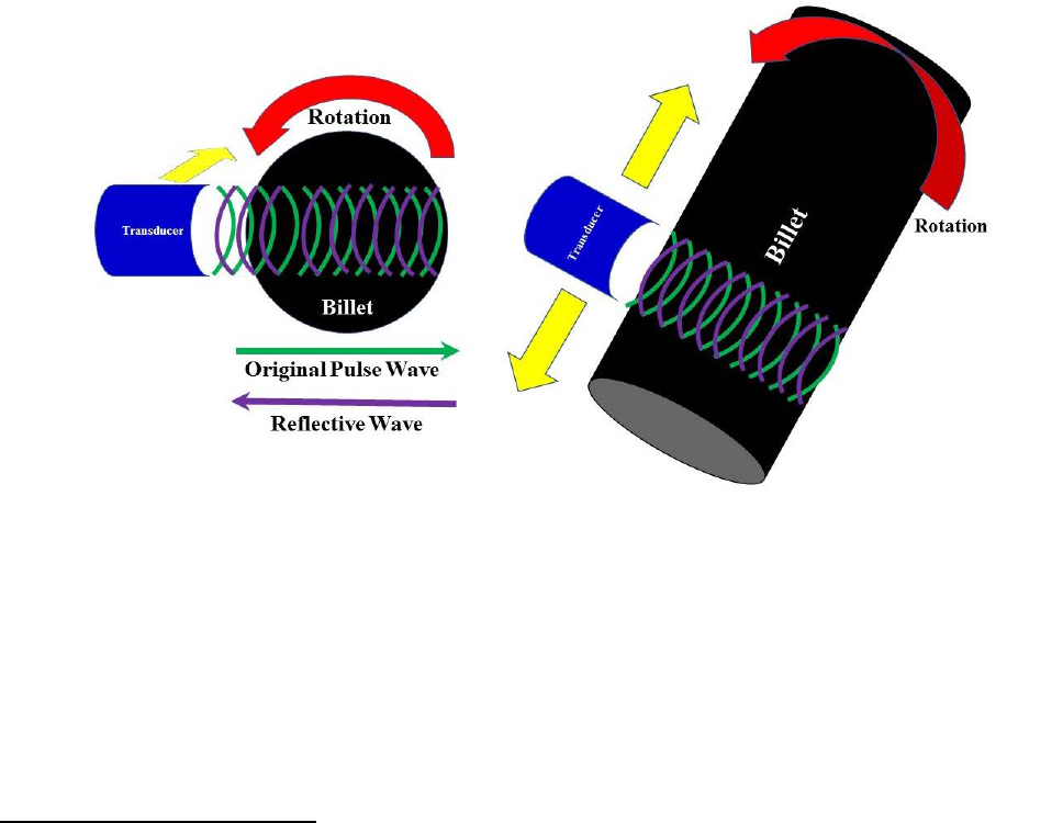
NTSB Aircraft Accident Report
12
determining the position, shape, and possibly the size of those anomalies. ATI SM uses a
longitudinal wave water immersion, pulse-echo ultrasonic inspection technique in which the billet
is submerged in a water tank and rotated while two transducers move longitudinally along the
length of the billet. The rotation of the billet ensures that its entire diameter is inspected by the
combination of the two transducers. The technique involves a pulsed sound wave from a transducer
that propagates through the material and reflects off any discontinuity, such as a void (an internal
cavity), crack, or variation in material density, providing an echo back to the transducer.
The location of a discontinuity can be determined by comparing the amount of time for the
echo to return to the transducer with the normal reflective wave from a known discontinuity.
Although the size of a discontinuity can be determined by the strength (amplitude) of the echo
return, this information must also be correlated with a known defect size. The advantage of this
technique is the ease of moving the transducer along the material while both remain acoustically
coupled.
28
Figure 4 shows a representation of a longitudinal wave scan.
Figure 4. Longitudinal wave scan used during ultrasonic inspections.
Before the ultrasonic inspection, the top and bottom of a billet are cut off because these
areas are where defects are most likely to have formed. Additional cuts at the top and bottom of
the billet are made for visual macroscopic inspection. The final steps before the ultrasonic
inspection are a machining operation termed “peeling” and polishing to enhance the effectiveness
of the inspection. ATI SM uses the requirements of GE specification P3TF15, titled “Ultrasonic
Inspection of Billet – Immersion,” class C and class E, for the billets.
29
As part of the inspection
process, any identified defects are cut out of the billet material for evaluation, and an ultrasonic
28
The immersion transducer uses the water to facilitate the transmission of acoustic waves from the transducer
to the material to be inspected. The transducer cables are electrically sealed and waterproof.
29
GE specification P3TF15 called for the surface finish for the polishing step to be 125 microinches or better,
which “will normally ensure inspectability.” A microinch (µin) is equal to one-millionth of an inch. Class C refers to
alloy 718 (fine grain), and class E refers to general applications (high sensitivity).

NTSB Aircraft Accident Report
13
billet map sheet is created for each billet to provide the location of any defects that were cut out of
the material.
1.3.1.3 Manufacture History of Accident HPT Stage 2 Disk
According to ATI SM production records related to the accident HPT stage 2 disk, the
triple-melt process produced five ingots, designated as FA94-1 through -5, from the master heat,
and the ingot designated as FA94-2 was the one from which the HPT stage 2 disk was
manufactured. ATI SM stated that the furnaces that were used to produce these ingots were still in
use at the company’s facility (as of November 2017). Ingot FA94-2, which became billet FA94-2,
was forged into a 10-inch-diameter round. The ultrasonic inspection technique that ATI SM used
for billet FA94-2 was the same as that in use as of November 2017, and the equipment that was
used for inspecting the billet was the same design as the equipment in use as of November 2017.
30
Review of the ultrasonic billet map sheet for FA94-2 showed no defects or rejections in the billet
material.
31
Two companies, in addition to ATI SM, were involved in manufacturing the HPT stage 2
disk that was delivered to GE: Wyman-Gordon of Houston, Texas, and Motoren- und
Turbinen-Union GmbH (MTU) of Germany. Once billet FA94-2 was deemed acceptable (that is,
it passed all required inspections), ATI SM cut the billet to the lengths specified by
Wyman-Gordon. Review of the ATI SM certification test sheet (used to certify billets) for FA94-2,
dated June 17, 1997, indicated that (1) the metallography, microstructure, and grain size were
acceptable per specifications; (2) an ultrasonic inspection was performed with no defects found;
and (3) macroscopic inspection results were acceptable.
ATI SM sent the billet to Wyman-Gordon, which further cut the billet into nine pieces,
with each piece representing the precise length of material needed to manufacture the intended
part. These pieces were press forged, heat treated, and rough machined. Wyman-Gordon certified
the forging on August 8, 1997, and sent the forged pieces to MTU for additional inspections and
final machining.
MTU performed ultrasonic inspections (with the pulse-echo technique, similar to ATI SM)
on “sonic-shape” forged pieces using its own work instructions, which GE approved.
32
MTU’s
work instructions met GE specification P3TF1, titled “Ultrasonic Inspection,” class A longitudinal
30
The transducers for the ultrasonic equipment need to be replaced periodically to prevent calibration issues
resulting from deterioration.
31
For FA94-1, the ultrasonic billet map showed a “macro-rejectable” defect in the bottom of the billet, so
additional material was removed. For FA94-3, the ultrasonic billet map showed a “sonic-rejectable” indication in the
top of the billet, so material containing the indication was removed, and the defect was located and identified. For
FA94-4, the ultrasonic billet map showed a sonic-rejectable indication in the top of the billet, so material containing
the indication was removed, but the indication could not be identified after the material was removed. For FA94-5,
the ultrasonic billet map showed a macro-rejectable indication in the bottom of the billet, so additional material was
removed.
32
MTU performed pre-machining and cleaning operations before the ultrasonic inspection; those operations
produced the forging shape configurations (referred to as sonic-shape pieces) for the inspection.

NTSB Aircraft Accident Report
14
and circumferential shear ultrasonic requirements.
33
Afterward, additional machining,
shot peening, a final visual and dimensional inspection, and a high-sensitivity fluorescent
penetrant inspection (FPI), per a GE specification, were performed. Review of the MTU final
inspection sheet for the HPT stage 2 disk, dated February 3, 1998, indicated that the completed
disk was acceptable. In March 1998, MTU sent the HPT stage 2 disk to GE, which installed the
disk in the CF6-80C2B6 turbofan engine that was eventually installed on the right side of the
accident airplane. The engine serial number (ESN) for the right engine was ESN 690-373.
1.3.2 Accident Engine Maintenance Events
On April 30, 1998, Boeing delivered a 767 airplane to American Airlines with
ESN 690-373 (including the HPT stage 2 disk involved in this event) installed; that airplane was
registered as N392AN. On March 25, 2007, American Airlines removed ESN 690-373 from
N392AN and sent it to the company’s Tulsa, Oklahoma, engine maintenance facility to, among
other things, accomplish the mandatory inspection requirements of FAA Airworthiness Directive
(AD) 2002-07-12, which were to be performed on the HPT stage 2 disk at “each piece-part
opportunity.”
34
To satisfy the AD’s HPT stage 2 disk inspection requirements, maintenance
personnel performed FPIs and eddy current inspections (ECI) of the HPT stage 2 rim bolt holes
and the disk bore. Initial FPI results revealed that the bolt holes needed repairs, which were made;
follow-up FPI results revealed no other disk anomalies. Maintenance personnel reinstalled the HPT
stage 2 disk into the same engine and, on September 16, 2007, installed ESN 690-373 in company
767 airplane N386AA.
On January 15, 2011, American Airlines removed ESN 690-373 from N386AA and sent it
to the company’s Tulsa maintenance facility for scheduled heavy maintenance. Among other
things, maintenance personnel removed the HPT stage 2 disk from the engine and performed all
mandatory inspections as well as visual and dimensional inspections. Among the mandatory
inspections performed were those required by AD 2009-04-10, which superseded
A 2002-07-12.
35
Regarding the CF6-80C2 HPT stage 2 disks, AD 2009-04-10 had the same ECI
and FPI requirements as those mandated by AD 2002-07-12, and maintenance personnel
documented no anomalies when performing those inspections. Maintenance personnel reinstalled
the HPT stage 2 disk into the same engine and, on May 12, 2011, installed ESN 690-373 in the
right engine position of the accident airplane (N345AN).
33
GE specification P3TF1 called for a surface finish of 90 microinches for longitudinal wave and circumferential
shear wave, which “will usually provide ultrasonic inspection with acceptable surface noise effects.” Class A refers
to immersion ultrasonic inspection.
34
FAA AD 2002-07-12, “General Electric Company CF6-80A, CF6-80C2, and CF6-80E1 Series Turbofan
Engines” (67 Federal Register 17279, April 10, 2002), effective May 15, 2002, stated the following: “within the next
30 days after the effective date of this AD, revise the manufacturer’s Life Limits Section of the Instructions for
Continued Airworthiness…and for air carrier operations revise the approved continuous airworthiness maintenance
program” by adding the mandatory inspections detailed in the AD for life-limited rotating engine parts. According to
the AD, “piece-part opportunity” meant that “the part has accumulated more than 100 cycles-in-service since the last
piece-part opportunity inspection, provided that the part was not damaged or related to the cause for its removal from
the engine” (FAA 2002).
35
FAA AD 2009-04-10, “General Electric Company CF6-80A, CF6-80C2, and CF6-80E1 Series Turbofan
Engines” (74 Federal Register 7995, February 23, 2009), effective March 30, 2009, incorporated additional inspection
requirements (FAA 2009).

NTSB Aircraft Accident Report
15
On November 11, 2013, American Airlines removed ESN 690-373 from the airplane for
reliability improvement program tasks while at the company’s Tulsa maintenance facility.
Maintenance personnel did not disassemble the HPT rotor and thus did not inspect the HPT stage 2
disk. On December 4, 2013, maintenance personnel reinstalled ESN 690-373 in the right engine
position of the accident airplane, where it remained through the time of the accident.
As previously stated, the right engine had accumulated 10,984 total cycles since new. The
HPT stage 2 disk has a life limit of 15,000 cycles when installed on the CF6-80C2B6 engine. Thus,
at the time of the accident, the HPT stage 2 disk had 4,016 cycles of in-service life remaining.
Also, since the time of the right engine’s shop visit in January 2011 (the last time before the
accident that the HPT stage 2 disk was removed from the engine and inspected), the engine had
accumulated 19,139 hours and 3,057 cycles.
1.3.3 Postaccident Engine Observations
The HPT stage 2 disk of ESN 690-373 (right engine) was recovered on scene in four
fragments, as shown in figure 5. About 96% of the disk, including the entire disk bore, was
recovered.
36
As mentioned in section 1.1, one disk fragment (labeled “A” in figure 5), which
weighed about 56.6 pounds, was recovered on the airport property in a UPS warehouse located
about 2,935 ft south of the airplane’s position on the runway where the uncontained engine failure
occurred.
37
36
After the accident, 71 of the 74 blade retaining posts in the HPT stage 2 disk were recovered. In addition,
smaller pieces of engine debris were recovered at or near the location on the runway where the uncontained engine
failure occurred.
37
The disk fragment penetrated the roof of the UPS warehouse and was found on the floor.

NTSB Aircraft Accident Report
16
Figure 5. Main fragments of the HPT stage 2 disk (forward side).
The other three disk fragments (labeled “B,” “C,” and “D” in figure 5) were recovered on
the airport property north of runway 28R. These three disk fragments were located 475 ft
(fragment D), 1,365 ft (fragment B), and 1,500 ft (fragment C) from the airplane’s location on the
runway where the uncontained engine failure occurred. Specifically, fragment B, which weighed
about 83.1 pounds, was recovered in the grassy area near a taxiway; fragment C, which weighed
about 6.6 pounds, was recovered on another taxiway; and fragment D, which weighed about
0.2 pound, was recovered on the overrun area at the departure end of runway 15.
38
Figure 6 shows
the disk fragment locations overlaid on a map of the airport.
38
According to GE, without blades or thermal shield attachment bolts, the HPT stage 2 disk weighs about
153 pounds. The disk fragment weights in this section reflect the weight with blade shanks and attachment bolts
removed when possible.

NTSB Aircraft Accident Report
17
Figure 6. Disk fragment locations.
On-scene examination of the right wing (inboard of the right engine pylon) revealed two
distinct penetration holes.
39
One hole (referred to as hole 1) was located forward of the front spar
in the leading-edge panel; the other hole (referred to as hole 2) was located aft of the wing front
spar. Figure 7 shows holes 1 and 2.
Figure 7. Holes located forward and aft of the right wing front spar.
39
All right wing impact damage from exiting HPT stage 2 disk or engine debris was observed inboard of the right
engine pylon.

NTSB Aircraft Accident Report
18
The on-scene examination also revealed the following:
• fragments of the ruptured HPT stage 2 disk, along with blade and vane fragments,
penetrated through the HPT case and right engine nacelle structure;
• small engine hardware fragments impacted the right side of the fuselage and the left and
right main landing gear doors;
• small engine hardware fragments penetrated the left engine nacelle, with no engine damage
observed;
• a disk fragment, along with smaller engine hardware fragments, impacted the right engine,
right wing, and portions of the right fuselage, severing the main engine fuel feed line and
breaching the right-wing fuel tank, which led to a fuel-fed fire; and
• another disk fragment, along with smaller engine hardware fragments, created multiple
impact scars on runway 28R.
40
1.3.4 Metallurgical Examinations
The NTSB’s Materials Laboratory in Washington, DC, examined the three largest HPT
stage 2 disk fragments (A, B, and C; see figure 5). Visual examination found a discolored
(heat-tinted) region on the fracture surfaces separating fragments A and B.
41
The discolored region
was at the forward end of the disk bore region, as indicated in figures 8 and 9, and this region was
identified as the location where the fracture originated.
40
The main impact scar was a gouge that was consistent with the impact from exiting HPT stage 2 disk fragments.
The gouge was oriented about 30° forward of the direction of airplane travel (relative to the HPT stage 2 plane of
rotation) and in the general direction where three separate fragments of the HPT stage 2 disk were located (north of
runway 28R). The gouge measured about 33 inches long, 8 inches wide, and 2 inches deep and was located about 32
ft to the right of the runway 28R centerline.
41
The fracture surfaces comprised right and left sides. The right sides were on disk fragment A, and the left sides
were on disk fragment B.

NTSB Aircraft Accident Report
19
Figure 8. Engine cross-section and fracture origin location.
Figure 9. Fracture surface from disk fragment A.

NTSB Aircraft Accident Report
20
Metallurgical examination of the fracture surfaces revealed multiple subsurface
microstructural discontinuities with multiple cracks initiating along the boundary of the
discontinuities. The discontinuities, which had a dark gray appearance, were elongated in the
direction of, and aligned with, the grain structure pattern produced during forging. The
discontinuities spanned a total length of about 0.78 inch, with the largest of the discontinuities
measuring about 0.43-inch-long by 0.07-inch-wide and having an inclination of about 26º from
the bore centerline.
Multiple cracks had initiated along the upper and lower edges of the discontinuities and
progressed toward the disk rim and disk bore. Scanning electron microscope (SEM) images of the
fracture surface revealed relatively coarse striations at regularly spaced intervals, consistent with
crack growth by low-cycle fatigue, followed by a transition to cyclic tensile crack growth and then
tensile overstress.
42
The net size of the cracked region immediately before the disk fracture (given
the size of the discolored region) ranged from about 0.47 to 0.93 inch in the radial direction and
about 0.96 inch to 1.13 inches in the axial direction and encompassed an area of about
0.82 square inch.
SEM examination of the discontinuities on the fracture surface showed that the
discontinuities were regions of discrete micron-sized oxide particles, referred to as stringers,
embedded in a material consistent with alloy 718. A polished and acid-etched metallurgical
cross-section through the largest of these features showed that these oxide stringers surrounded
and were interspersed in a discrete underlying region where the alloy 718 grain size was coarser
than the surrounding material. The coarse grain region beneath the discontinuity exhibited a white-
etched appearance compared with the surrounding fine grain material due to the acid etch. The
stringers and coarse grain region collectively formed a subsurface anomaly referred to as a
“discrete dirty white spot” that measured about 0.15 by 0.10 inch.
43
Figure 10 shows the discrete
dirty white spot, and figure 11 shows a close-up view of one of the stringers.
42
Striations are linear features on a fatigue fracture surface that indicate how far a crack advanced with each
stress cycle. The NTSB selected three of six cracks for striation density measurements to estimate the number of low-
cycle fatigue crack growth cycles before the disk ruptured. In airplane engines, low-cycle fatigue is associated with
one striation per flight cycle. For information about the NTSB’s work in this area, see section 1.4.1.
43
If stringers are present, a white spot is “dirty”; if stringers are absent, a white spot is “clean.” Section 1.7.1
provides information about white spot formation as it related to the manufacturing process for the HPT stage 2 disk.

NTSB Aircraft Accident Report
21
Figure 10. Discrete dirty white spot in fracture surface.
Figure 11. Stringer in material microstructure.
Crack
Stringers
Discrete dirty
white spot
Fracture surface/stringer
Fracture
Radially
Figure 11

NTSB Aircraft Accident Report
22
GE Aviation’s Materials Laboratory in Evendale, Ohio, performed additional metallurgical
examinations on the disk segments and produced a report detailing its findings (Morales 2017).
This work included additional striation density measurements (discussed in section 1.4.1),
hardness measurements, microprobe chemical analysis of the discrete dirty white spot, additional
cross-section metallography, and bulk alloy chemistry. The report stated that the hardness,
chemistry, and grain size of the material away from the discrete dirty white spot was within the
blueprint requirements for the disk and that GE’s cross-sections through the discrete dirty white
spot found stringers with no voids.
GE and ATI SM conducted a study of discrete dirty white spots “to better understand their
ultrasonic response characteristics.” The report detailing the study results is discussed in
section 1.4.2.
1.4 Tests and Research
1.4.1 Number of Flight Cycles in Low-Cycle Fatigue Regions
As previously stated, the NTSB documented the presence of multiple fatigue cracks that
initiated at a discrete dirty white spot in the forward bore region of the HPT stage 2 disk. The
NTSB and GE estimated flight cycles for a total of six cracks, numbered 1 through 6, as shown in
figure 12. The cracks exhibited striated features consistent with low-cycle fatigue.
Figure 12. Fatigue cracks that initiated from discrete dirty white spot.
The NTSB selected cracks 1, 2, and 6 for a study to estimate the number of flight cycles in
each low-cycle fatigue region. (The NTSB focused on these cracks for the study because they did
not emerge from the surface.) SEM images were taken for each of the cracks (along the path of
crack progression up to the transition to cyclic tensile crack growth), and striation densities were
measured on those images to estimate the number of cycles from crack initiation to the HPT stage 2
disk failure. The study assumed that one striation correlated with one flight cycle and that the
NTSB Aircraft Accident Report
23
forces during takeoff, when the stresses on the HPT stage 2 disk would be at their highest, caused
the crack to progress. The study results showed that cracks 1, 2, and 6 progressed by low-cycle
fatigue for about 5,700, 5,600, and 3,700 cycles, respectively.
GE made striation density measurements for all six cracks, which showed that the greatest
striation count, assuming one striation per mission/flight cycle, was about 7,000 cycles before the
disk ruptured in tensile overload. This striation density measurement estimate was for crack 6,
which progressed outward and did not reach the bore of the disk. GE’s estimates for cracks 1 and 2
were 6,000 and 5,900 low-cycle fatigue crack growth cycles, respectively. (The NTSB notes that
striation density measurements can be affected by subjectivity in measuring the striation densities
and interpreting the results.) GE’s striation density measurement estimates for cracks 3, 4, and 5
indicated that the cracks progressed by low-cycle fatigue for 1,400, 1,200, and 3,200 cycles,
respectively.
1.4.2 Ultrasonic Response Characteristics of Discrete Dirty White Spots
As stated in section 1.3.4, GE and ATI SM conducted a study of discrete dirty white spots
to better understand their ultrasonic response characteristics. GE provided the NTSB with a report
on the results of the study.
ATI SM selected and characterized six discrete dirty white spots found by ultrasonic
inspection of alloy 718 billets during the 2.5 years before the study was completed (in April 2017).
According to GE’s report, the sample represented “a typical range of sizes, shapes, stringer
distribution, and radial position observed historically.” GE performed further characterization of
the six discrete dirty white spots, including metallographic examination. Voids/cracks were found
in five of the six discrete dirty white spots; findings for one discrete dirty white spot were
inconclusive.
The report concluded that voids/cracks in discrete dirty white spots might provide a
reflection surface that is conducive to ultrasonic detection (GE 2017). Specifically, the report
compared one of the sample discrete dirty white spots with the discrete dirty white spot found on
the HPT stage 2 disk from the accident airplane. The sample discrete dirty white spot had multiple
voids along a stringer, which made detection via ultrasonic inspection likely. The discrete dirty
white spot on the HPT stage 2 disk from the accident airplane showed no voids, and, as previously
stated, ultrasonic detection performed during manufacturing of the billet did not detect any
anomalies.
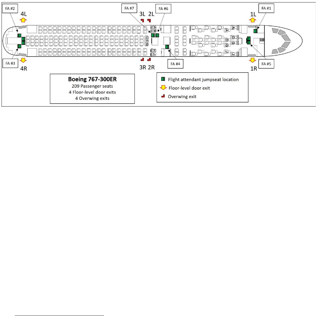
NTSB Aircraft Accident Report
24
1.5 Survival Aspects
The airplane was configured with 2 flight crew seats (and a cockpit jumpseat, which was
unoccupied during the accident flight), 10 flight attendant jumpseats (3 of which were
unoccupied), and 206 passenger seats.
44
The airplane had four door exits and four overwing exits.
Figure 13 shows the airplane configuration and the seating positions within the cabin for the seven
flight attendants.
Figure 13. N345AN configuration.
1.5.1 Interphone Communication System
The airplane’s interphone communication system comprised a flight crew interphone and
five flight attendant interphones, which enabled voice communications to and from the flight deck
and five flight attendant locations (1L, 1RC, 2R, 4L, and 4R jumpseats). The interphones were
also used to make PA announcements and enable communication between flight attendant
locations.
American Airlines 767-300-series airplanes have two different interphone models: the
“classic” model, shown in figure 14a, which was installed on 767C-300ER airplanes delivered
before January 2003, and the “new” model, shown in figure 14b, which is installed on
767N-300ER airplanes delivered beginning in January 2003. The accident airplane, delivered in
April 2003, had the new model interphone system installed.
44
The three unoccupied jumpseats were at the 1LC (left center), 4LC, and 4RC (right center) positions.

NTSB Aircraft Accident Report
25
Figure 14a. Classic model interphone.
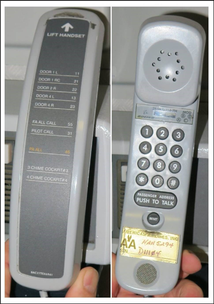
NTSB Aircraft Accident Report
26
Figure 14b. New model interphone.
The classic model interphone has a key pad with four keys (buttons) to call locations within
the airplane. The new model interphone has a key pad that resembles a standard telephone key
pad. On the back of the new model interphone is a list of 10 communication options for making
calls to various locations within the airplane. According to American Airlines flight attendant
interphone procedures, although the classic and new model interphones both required flight
attendants to activate the interphone buttons slowly and pause between each high/low chime to

NTSB Aircraft Accident Report
27
allow the chiming cycle to complete, the procedures for placing routine and emergency calls
between the cockpit and the cabin differed between the models.
45
Section 1.5.2 describes the experience of three flight attendants with the interphone during
the emergency. Also, section 1.6.3.2 discusses flight attendant training, including the use of
simulators. The classic model interphone was installed on one of two Boeing 767 simulators used
for flight attendant training. The other 767 simulator had a nonfunctioning mockup of the new
model interphone.
1.5.2 Evacuation
After the airplane came to a stop (1432:10), the flight attendants began evacuating the
airplane. FDR data showed that, at 1432:20 (10 seconds after the airplane came to a stop), the left
overwing exit opened. The forward left (1L) and forward right (1R) cabin doors opened 18 and
22 seconds later, respectively. At 1432:48 (38 seconds after the airplane came to a stop), the aft
left (4L) cabin door opened. The left engine was shut down at 1433:09.
American Airlines provided the NTSB with two videos of the accident airplane that were
taken by witnesses. One video was 2 minutes 28 seconds long, and the other video was 57 seconds
long. Both videos show only the left side of the airplane. Also, the videos do not show the time
that the last passenger evacuated via the left overwing exit slide. From the available information
on those videos, the NTSB determined the timeline of evacuation events shown in table 2.
Table 2. Evacuation events shown on videos of left side of airplane.
Elapsed time (min:sec) Event
0:00
Airplane comes to a stop.
0:15
Left overwing exit opened.
0:19
Left overwing exit slide fully deployed.
0:31
First occupant evacuated via left overwing exit slide.
0:31
1L door opened.
0:37
1L slide fully deployed.
0:40
4L door opened.
0:44
First occupant evacuated via 1L slide.
0:46
4L slide fully deployed but initially unusable—blown aft by left
engine. (Slide remained attached to airplane.)
1:09
4L slide repositioned forward unassisted.
1:11
4L slide fully deployed and usable.
1:25
First occupant evacuated via 4L slide.
2:02
Airport operations vehicle arrives.
2:11
Last occupant evacuated via 1L slide.
2:21
Last occupant evacuated via 4L slide.
Note: The FDR “door open” signal occurred 2 to 5 seconds before the left overwing exit and the 1L and 4L doors were observed to
open. The FDR door open signal is driven by a door proximity sensor that indicates that a door was unlocked or that a door handle
changed position. As a result, the FDR door open signal would not be expected to occur at the same time as opening of the overwing
exit and doors, which is why the FDR showed that the left overwing exit opened 10 seconds after the airplane came to a stop and the
video showed that the left overwing exit opened 15 seconds after the airplane came to a stop.
45
For example, for a routine call to the flight deck, flight attendants were to press the “Pilot” button twice on the
classic model interphone or enter “31” on the new model interphone. Also, for an emergency call to the flight deck,
flight attendants were to press the “Alert” button four times on the classic model interphone or enter “#4” on the new
model interphone.

NTSB Aircraft Accident Report
28
The NTSB conducted postaccident interviews with the flight attendants, who reported that,
after hearing a loud noise (described as a “bang” or a “boom”) and feeling the airplane “shudder,”
“shake,” and “fishtail,” passengers began moving from the right to the left side of the airplane
while it was still moving down the runway. Once the airplane came to a complete stop, passengers
started rushing toward the exits and urged the flight attendants to open the doors so that the
passengers could evacuate. Table 3 summarizes the flight attendants’ actions before and during
the evacuation.
46
Two flight attendants reported that they were not able to properly use the
interphone. These two flight attendants also reported the 4L door slide could not be immediately
used after it deployed because it was blown aft before the left engine had been shut down. (The
slide remained attached to the airplane.) In addition, two flight attendants reported passengers
evacuating with baggage despite being directed to leave their bags behind.
Table 3. Summaries of flight attendant evacuation actions.
Flight attendant
position and location
Evacuation actions
FA 1(lead)/1L jumpseat
After the airplane came to a complete stop, flight attendant 1 stood up to assess
his area and waited for a call from the cockpit. Passengers started to rush the 1L
door area, requesting him to open the door so that they could exit the airplane. He
recalled picking up the interphone but did not remember if he called the cockpit.
After he saw a “haze of smoke” aft of the first-class cabin, he opened the 1L door
and initiated the evacuation. He continued the evacuation until all passengers had
exited. He told the flight crew that the cabin was clear and then exited from the 1L
door.
FA 2/4L jumpseat
Flight attendant 2 saw flames coming from the right wing. She reported that
passengers were immediately at the 4L door, pleading to get off the airplane. She
attempted to contact the flight crew about the left engine but was unsuccessful
because she selected the wrong button on the interphone. Passengers were
continuing to plead with her to let them off the airplane. She continued to hold off
passengers to allow more time for the flight crew to shut down the left engine. The
cabin began filling with smoke, and she was concerned because the airplane was
heavy with fuel, so she decided to allow passengers to evacuate from the 4L door.
The slide deployed but was blown aft because the left engine was still running.
She and flight attendant 3 held back passengers until the engine stopped running
and the slide stabilized itself, and then they began the evacuation. Once flight
attendant 2’s area was clear, she exited the airplane from the 4L door.
FA 3/4R jumpseat
Flight attendant 3 reported that the cabin was “lit up” on the right side of the
airplane back to the 4R door. Before the airplane came to a stop, passengers
were screaming, climbing over seats, and moving to the left side of the airplane.
He picked up the interphone to make a PA announcement instructing passengers
to remain calm, but he did not make the announcement because he could not
recall how to use the interphone. He moved to the 4L door area to assist flight
attendant 2 as passengers asked them to open the door so that they could get out
of the airplane. He and flight attendant 2 were waiting to hear from the captain
and for the left engine to shut down before they began the evacuation. While they
were waiting, the cabin began to fill with smoke, so they decided to open the 4L
door. Once the door was opened, he saw the slide blowing. Once the slide
stabilized, he evacuated passengers until his assigned area was clear and then
exited from the 4L door.
FA 4/2R jumpseat
Flight attendant 4 reported that she heard a loud explosion and saw fire.
Passengers jumped up out of their seats, even though the airplane was still
moving. She shouted at the passegers, “remain seated” and “heads down,” but
they continued to rush toward her jumpseat. The airplane came to a complete
46
For more information, see the flight attendant interviews (Survival Factors Attachment 1) in the docket for this
accident investigation, DCA17FA021
.

NTSB Aircraft Accident Report
29
Flight attendant
position and location
Evacuation actions
stop, and she instructed the passengers to “get out.” Her exit was unusable, so
she ran to the first-class cabin area, saw that the forward doors were open, and
redirected passengers to the front of the airplane. Passengers were trying to get
their bags out of the overhead bins, so she told them repeatedly, “don’t take
anything with you.” She went to the 2L overwing exit and saw flight attendant 7
evacuating passengers out of the window exits, so she also directed passengers
to those exits. A passenger came toward her exit with a bag; she told him to leave
the bag, but he did not follow directions and evacuated with the bag over his
head. Her location in the cabin was getting smoky, and she feared that the
airplane would explode, so, after checking for passengers, she evacuated from
the 2L overwing exit.
FA 5/1RC jumpseat
Flight attendant 5 was waiting for the flight crew to tell the flight attendants what
had happened during the takeoff attempt when passengers started rushing toward
her shouting, “fire, open the door.” She did not initially see fire but noted that flight
attendant 1 had opened the 1L door after seeing smoke in the cabin. Flight
attendant 5 assessed the conditions using the 1R door window, saw no fire, and
opened the door. She then saw fire outside and blocked the exit by holding up her
hands to stop passengers from using that exit. She shouted at passengers to use
the 1L door and continued blocking the 1R door. Once all passengers had
evacuated, she exited from the 1L door.
FA 6/2L jumpseat
After the airplane came to a complete stop, flight attendant 6 looked out a window
on the right side of the airplane and saw fire. She turned around toward the 2L
overwing exit. Flight attendant 7 was opening that exit, so she started directing
passengers to the open exits. A passenger came to the area with a large bag, and
flight attendant 6 instructed the passenger to leave the bag and evacuate the
airplane. The passenger did not listen, so flight attendant 6 tried to take the bag
away from the passenger. The flight attendant realized that the struggle over the
bag was causing a delay in the evacuation, so the passenger evacuated the
airplane with her bag. Once the area was clear, flight attendant 6 exited from the
2L overwing exit.
FA 7/3L jumpseat
Flight attendant 7 saw a “plume of fire” over the right wing and black smoke and
reported that passengers started jumping out of their seats while the airplane was
still moving. He yelled, “stay down,” but the passengers did not listen. Once the
airplane came to a complete stop, he opened the 2L overwing exit, even though it
was flight attendant 6’s assigned exit, and started commanding passengers to
evacuate out the window exits on the left side of the airplane. Flight attendant 7
also directed passengers forward toward the first-class section. The cabin was
starting to fill with “hazy gray smoke,” and he thought that the interior panels were
burning and could see the window glass melting on the right side. After the
passengers had evacuated, he exited from the 2L overwing exit.
The NTSB also interviewed four passengers from the flight. One of these passengers, who
occupied a seat near the 3L overwing exit, reported that everything appeared to be normal during
the takeoff roll until he heard a loud “bang” and saw what appeared to be “orange sparks.” He also
reported that the flight attendant sitting in front of him instructed passengers, in a forceful yet calm
manner, to sit down. As soon as the airplane came to a stop, he opened the exit. He stated that he
had not heard an evacuation command but was “very focused” on getting the exit open.
In addition, the NTSB interviewed the passenger who sustained the serious injury during
the evacuation. The passenger exited the airplane using the left overwing exit slide. He reported
that, after reaching the ground, he stood up to get away from the airplane and was “blown over”
by the jet blast coming from the back of the left engine. He also reported that, as he stood up again
and ran to a grass strip next to the runway, he felt pain in his back.
NTSB Aircraft Accident Report
30
1.6 Organizational Information
1.6.1 American Airlines Flight Crew Manuals
1.6.1.1 Engine Fire Checklist
The American Airlines B767 Operations Manual, QRH included a checklist procedure
(dated March 11, 2015) for an engine fire (or engine severe damage or separation) occurring on
the ground or in flight. This checklist was based on the checklist in Boeing’s 767 Flight Crew
Operations Manual QRH for the same engine emergencies. The first five items on the checklist,
which detailed actions to be taken immediately in response to the engine emergency, were to be
performed from memory. The remaining 11 items on the checklist, which were to be accomplished
using the checklist, included actions related to configuring the airplane for landing. The five
memory items, as well as the messages and conditions, on the checklist were as follows (bold face
type indicated in original):
Messages: L ENGINE FIRE R ENGINE FIRE
Condition: One or more of these occur:
• Engine fire warning
• Airframe vibrations with abnormal engine indications
• Engine separation
1. A/T ARM switch…………………………………………………. OFF
2. Thrust lever
(affected side)……………………… confirm……….…………………Idle
3. FUEL CONTROL switch
(affected side)…………………….…confirm……….…………...CUTOFF
4. Engine fire switch
(affected side)……………………….confirm………………………... Pull
5. If the engine fire warning light is illuminated:
Engine fire switch
(affected side)……………...…Rotate to the stop and hold for 1 second

NTSB Aircraft Accident Report
31
If after 30 seconds the engine fire warning light stays illuminated:
Engine fire switch
(affected side)……………Rotate to the other stop and hold for 1 second
Figure 15 shows the engine fire switches, also referred to as engine fire handles, as
described in steps 4 and 5 of the checklist.
Figure 15. Engine fire handles.
Note: Only the unlock button for the left engine fire handle is labeled. A similar unlock button appears forward of the
right engine fire handle.
1.6.1.2 Evacuation Guidance
The American Airlines B767 Operations Manual, QRH (dated April 7, 2016) provided the
following evacuation guidance in the “General Information” section (bold face type indicated in
original):
After an airplane has landed following a significant in-flight event, the potential
exists for a passenger or Flight Attendant initiated evacuation. If an immediate
NTSB Aircraft Accident Report
32
evacuation is not required, it is important to assure the passengers and Flight
Attendants that the situation is under control. Make an immediate PA commanding:
‘This is the Captain. Remain Seated. Remain Seated. Remain Seated.’
If an evacuation might be required after further assessment, consideration should
be given to configuring the aircraft for a potential evacuation. (Steps such as
shutting down the engines should be considered to avoid the potential passenger
injuries which might occur if the aircraft is not configured and the situation
deteriorates or an inadvertent passenger or Flight Attendant evacuation takes
place.)
The guidance also stated that the “primary evacuation signal” was the announcement, over
the PA system, “This is the Captain. Evacuate. Evacuate. Evacuate” (as shown in step 5 of the
evacuation checklist in section 1.6.1.3).
The American Airlines B767 Operations Manual, QRH also provided the following
evacuation decision-making guidance under “General Information”:
In a non-normal situation, the Captain must decide whether or not to conduct a
passenger evacuation. The Captain must balance the hazard of passenger
evacuation against the hazard of remaining on board. It is not feasible to establish
a rigid set of rules regarding evacuation since there are many situational variables.
The Captain must evaluate a specific situation, apply good judgment, and reach the
best decision given the information available. The emergency evacuation is a
powerful tool. Use it cautiously.
The Captain should consider the following:
• The decision to evacuate should be deliberate after carefully weighing the
risks in evacuating against the risks of remaining on board.
• The most hazardous event is fire or smoke within the pressurized area of
the airplane (cabin or cargo compartment).
• Smoke or flames in the engines, APU, or wheel assembly areas will
normally burn out quickly and not endanger the cabin. Request ARFF
equipment, pull the Fire Switch, discharge fire suppression agent as
appropriate, carefully monitor the area and communicate with crash vehicle
crews and tower. Time and conditions permitting, clear the active runway.
Evacuate the passengers if the fire does not extinguish in a reasonable time
or appears to be spreading.
Whatever the decision, be specific and unambiguous in conveying your intent to
the Flight Attendants.

NTSB Aircraft Accident Report
33
The QRH provided the following evacuation-related information related to the role of the
flight attendants under “General Information”:
Since most accidents occur on takeoff and landing, the Flight Attendants are
instructed to be alert to clues of an emergency situation, such as unusual impact
forces, noises, smoke, fire, or abnormal airplane attitudes. After the airplane stops,
the Flight Attendants will assess the situation and, if the need for an evacuation is
obvious, will initiate the evacuation without waiting for instructions from the
cockpit. A DOOR EICAS message indicates that the evacuation has started.
In addition, the American Airlines Flight Manual Part I, “Non-normal and Emergency”
(dated October 1, 2016), stated the following regarding flight attendant-initiated emergency
evacuations:
When an aircraft has come to a stop in an obvious life-threatening situation (fire,
dense smoke in the cabin, crash), Flight Attendants are authorized to initiate an
evacuation without awaiting instructions from the flightdeck. Flight Attendants will
attempt to communicate with the flightdeck if at all possible. If contact with the
flightdeck is not possible, or if life threatening conditions still exist, Flight
Attendants will make an independent decision and operate all usable exits.
1.6.1.3 Evacuation Checklist
The American Airlines 767 evacuation checklist procedure (dated April 7, 2016), appeared
on the back cover of the company’s B767 Operations Manual, QRH. The checklist was to be
announced by the first officer, performed by the captain, and verified by the first officer. The steps
of the checklist were as follows (bold face type indicated in original):
Condition: Evacuation is needed.
Note: Light override is available.
1. Parking brake……………………………….……………………...…Set
2. Cabin altitude MODE SELECT………………………………...MAN
[47]
3. CABIN ALTITUDE MANUAL control……………..…Hold in CLIMB
Note: Hold in CLIMB until the outflow valve indication shows fully open to
depressurize the airplane.
47
The 767 pressurization system has automatic and manual operating modes. The 767 pressurization panel,
located on the cockpit panel above the first officer’s seat, includes the cabin altitude mode select switch, which can
be set to the AUTO 1, AUTO 2, or MAN (manual) setting.

NTSB Aircraft Accident Report
34
4. FUEL CONTROL switches (both)…………………….………CUTOFF
5. PA…………………………………...……............“This is the Captain.
Evacuate, Evacuate, Evacuate.”
6. Evacuation COMMAND Switch
(as installed)…………………………………………………..………...ON
7. ATC………………………………………………………………Notify
8. Engine and APU
fire switches (all)………………………….……………. Override and pull
9. If an engine or APU fire warning occurs:
Related fire switch………………..Rotate to the stop and hold for 1 second
1.6.1.4 Evacuation Duties
The American Airlines B767 Operations Manual, QRH contained the following
information (dated March 11, 2015) regarding the flight crew’s responsibilities during an
evacuation:
48
Cockpit crewmembers will assist in the evacuation after completing required
cockpit duties and should wear their hats to identify themselves as authorities to the
passengers.
Captain – Assist in cabin
• After checklist is complete, immediately proceed to forward cabin and
assess conditions.
• Assist and direct evacuation. Pay attention to utilization of slides; use
megaphone, if required, to maintain orderly and rapid passenger evacuation.
Instruct Flight Attendants to leave airplane when their areas are clear.
• Check entire cabin to ensure that all passengers have evacuated. Exit via
any usable rear entry door.
• Assemble passengers away from airplane.
• Ensure that one or more crewmembers remain with the passengers until
relieved by station personnel.
48
The QRH also described “concurrent flight attendant duties,” including, once outside the airplane, assembling
passengers away from the airplane. Both flight crewmembers stated that, after evacuating the airplane, they saw the
flight attendants moving the passengers away from the airplane. Other concurrent flight attendant duties were making
a passenger count and reporting the count to the captain.

NTSB Aircraft Accident Report
35
First Officer – Assist outside airplane
• After checklist is complete, immediately proceed to forward cabin and
assess conditions.
• Take Halon fire extinguisher (if possible).
• Exit via first usable door and assist outside as necessary.
• Assemble passengers away from airplane.
1.6.2 American Airlines Flight Attendant Manual
American Airlines Flight Service Inflight Manual included the following information
(dated December 24, 2016) under the heading “General Principles of Evacuation”:
• If an emergency situation develops, be prepared to evacuate the aircraft.
Stay alert to clues that may signal a possible emergency.
o Unusual noises
o Impact forces
o Fire, sparks, or smoke
o Abnormal aircraft attitude
o The need to evacuate may not always be obvious. FAs must evaluate the
level of danger and clearly communicate any conditions that may
warrant an evacuation.
• Do not initiate an evacuation until the aircraft has come to a complete and
final stop.
o Be prepared for more than one impact.
o Be alert to any sense of motion, i.e., any sense of movement out the
window, or outside noises if vision is impaired.
• Begin evacuation command immediately upon signal from the flightdeck.
o If one FA initiates an evacuation, all FAs must initiate evacuation
procedures immediately by shouting evacuation commands.
The guidance also states that it is “critical” for flight attendants to update the captain if
cabin conditions warrant an evacuation because the flight crew might be unaware of
life-threatening situations, such as excessive smoke and/or fire. The guidance further stated, “if
the aircraft is on the taxiway and time permits, notify the flightdeck prior to initiating the
evacuation.”

NTSB Aircraft Accident Report
36
Further, the guidance included a table labeled “Evacuation Procedures.” The table
comprised nine procedural steps, including “on aircraft such equipped, turn on [evacuation]
signaling system” (step 3) and “prior to opening an exit, assess conditions outside to determine if
exit and escape route [are] safe” (step 4). Examples of unsafe conditions were provided, including
“fire or dense smoke” and “engine(s) still operating.”
Under the heading “FA and Flightdeck Crew Authority” (dated January 27, 2016), the
flight attendant manual includes the following information:
In a life-threatening situation, e.g., fire, smoke, impact forces, or abnormal aircraft
attitude, and when the aircraft has come to a complete stop, FAs have the authority
to initiate an evacuation without awaiting instructions from the flightdeck.
• FAs will attempt to communicate with the flightdeck prior to evacuation, if
possible.
• If contact with the flightdeck is not possible, FAs will make an independent
decision regarding evacuation and operate all usable exits.
The flight attendant manual further indicated that, during land evacuations, flight
attendants are to command passengers to “come this way” toward usable door and overwing exits
and “leave everything.”
Under the heading “767 Evacuation Signaling System” (dated March 11, 2015), the flight
attendant manual stated that signaling system control panels were located in the cabin on most
flight attendant jumpseats and in the cockpit.
49
In addition, the manual included a section on
interphone calls. This information (also dated March 11, 2015) described how to place and answer
calls. As previously stated, depending on their delivery date, 767 airplanes had one of two
interphone models—either the classic or the new model—and the procedures for placing calls
using each model are described in section 1.5.1.
1.6.3 American Airlines Training
1.6.3.1 Flight Crew Training
According to the American Airlines Flight Training B757/767 Instructor Guide –
Qualification Training, 12 days of ground school training were followed by 10 days of simulator
training. The simulator training was divided into simulator sessions, which were further divided
into various types of special purpose operational training, and concluded with a maneuvers
validation, line-oriented flight training, and a line operational evaluation.
49
According to Boeing, the evacuation signaling system control panels have a COMMAND switch, an EVAC
(evacuation) light, and a horn. Boeing indicated that, when the COMMAND switch is placed in the ON position, the
EVAC light illuminates and the horn sounds at each location with system control panels, including the cockpit.

NTSB Aircraft Accident Report
37
One special purpose operational training session titled “Rejected Takeoff (First Look),
Evacuation” comprised the following maneuvers:
50
• Takeoff
— Contingencies: Rejected Takeoff
• Takeoff
— Contingencies: Engine Fire
• Takeoff
— Contingencies: Evacuation
This training scenario involved either a cargo fire or an engine fire. During the training,
the flight crew was expected to perform a fire checklist and not initiate an evacuation until a flight
attendant called the cockpit to alert the flight crew of smoke in the cabin.
1.6.3.2 Flight Attendant Training
American Airlines uses two training facilities for company flight attendant training:
Flagship University and the Flight Academy, both of which are in Fort Worth, Texas. American
Airlines instructors conduct the training.
Initial new-hire training and recurrent (annual) training followed advanced qualification
program guidelines. Flight attendants received classroom instruction, web-based instruction,
hands-on door operation training in normal and emergency modes, and hands-on emergency
equipment training. Instructor-facilitated, scenario-based simulator training included full-scale
evacuations. In addition, American Airlines trained its flight attendants on the use of the
evacuation signaling system.
1.6.4 American Airlines Operating Manual—Engine Fire Warning System
According to American Airlines’ 757/767 Operating Manual, “Systems,” two detector
loops in each engine nacelle provide fire detection. Under normal circumstances, both loops must
detect a fire condition to cause an engine fire warning. An engine fire would be annunciated by
the following:
• sounding of the fire bell,
• illumination of the master WARNING light,
50
American Airlines described “first look” maneuvers as “maneuvers which are NOT briefed during the RTS
[recurrent training–simulator] briefing period but are flown by each pilot in the simulator and are defined to give some
indication of whether the interval between training sessions may be too long to maintain proficiency in rarely exercised
critical tasks” (capitalization indicated in original).

NTSB Aircraft Accident Report
38
• display of the EICAS warning message ENG FIRE (left or right),
• illumination of the engine fire switch (left or right) fire warning light (on the center
pedestal),
• illumination of the engine FUEL CONTROL (left or right) switch fire warning light
(on the center pedestal), and/or
• unlocking of the engine fire handle (left or right) to activate the fire extinguisher
bottle(s).
51
1.6.5 Boeing
The Boeing 767 Airplane Flight Manual included emergency procedures for responding to
an engine fire, severe engine damage, or an engine separation. The procedures, which the FAA
approved on May 12, 2005, stated that the following actions should be taken if an engine fire has
occurred:
Thrust Lever……………………………………………...…….…CLOSE
Fuel Control Switch…………………………………..…………CUTOFF
Engine Fire Switch…………..……………………………………...PULL
If fire warning light remains illuminated:
Engine Fire Switch………………………………...…………..ROTATE
After 30 seconds, if fire warning light remains illuminated:
Engine Fire Switch……………..ROTATE TO REMAINING BOTTLE
APU (if available)……..………………………………………...START
Prepare for one-engine inoperative landing.
This procedure (except for the last step) applied to engine fires that occurred on the ground
and during flight. The related checklist procedure in Boeing’s 767 Flight Crew Operations Manual
QRH (dated August 16, 2013) was based on the information in the Airplane Flight Manual. The
engine fire checklist procedure that American Airlines used (see section 1.6.1.1) was based on the
checklist procedure in Boeing’s 767 QRH.
51
To prevent an accidental activation of the fire extinguishing system, each fire handle is locked in its down
(non-activated) position by a solenoid-operated mechanical interlock device connected to the fire handle’s shaft. A
pilot can manually release a handle’s mechanical interlock by pressing a button located on the engine fire control
panel forward of the fire handle (see figure 15). The engine fire detection system can also automatically release the
mechanical interlock when the system detects an engine fire or overheat condition. Once the mechanical interlock is
released, a pilot can pull and rotate the engine fire handle.

NTSB Aircraft Accident Report
39
1.6.6 Federal Aviation Administration
1.6.6.1 Advisory Circular 20-128
Title 14 CFR 25.903(d)(1) states that, for turbine engine installations, “design precautions
must be taken to minimize the hazards to the airplane in the event of an engine rotor failure or of
a fire originating within the engine which burns through the engine case.” According to the
accident airplane’s FAA type certificate data sheet, the Boeing 767-300 was certified on
September 22, 1986. At that time, FAA Order 8110.11, Design Considerations for Minimizing
Damage Caused by Uncontained Aircraft Turbine Engine Rotor Failures, issued on November 19,
1975, was in effect. The order described, among other things, design considerations for critical
systems (including fuel systems) to minimize the damage that uncontained engine debris could
cause.
On March 9, 1988, the FAA issued AC 20-128, “Design Considerations for Minimizing
Hazards Caused by Uncontained Turbine Engine and Auxiliary Power Unit Rotor Failure.”
(FAA Order 8110.11 was canceled on May 1, 1988; AC 20-128 contained much of the same
information as the order.) AC 20-128 defined various fragment spread angles (based on historical
engine failure events) and the area of the airplane that would likely be impacted by uncontained
fragments resulting from an uncontained engine failure.
52
The AC also included a figure that
further explained fragment spread angles. The figure showed that, for a rotor burst event, an
airframe manufacturer was expected to assume that large disk fragments would exit the engine at
an angle that was ± 3° fore and aft from the center of the plane of rotation and that smaller disk
fragments would exit the engine at an angle that was ± 5° fore and aft from the center of the plane
of rotation. (These same fragment exit trajectories were specified in FAA Order 8110.11.)
On March 25, 1997, the FAA issued AC 20-128A in response to Safety Recommendation
A-90-170 (see section 1.7.3.1). The revised AC provided more recent information regarding rotor
bursts and blade release fragment trajectory data so that airframe manufacturers could take
appropriate design precautions to minimize the hazards to the airplane and its occupants. The
fragment spread angle information remained the same as in the previous version of the AC.
53
The
AC described accepted design precautions for uncontrolled fire, loss of thrust, loss of airplane
control, passenger and crew incapacitation, and structural integrity and indicated that airplane
designs would be evaluated against proven design practices for each.
54
In May 1999, the FAA issued a report titled Large Engine Uncontained Debris Analysis.
According to the report’s abstract, the objective of the analysis was to “define the debris, size,
weight, exit velocity, and trajectory that can be used to update [AC] 20-128A.” The abstract stated
that the results of the analysis showed that, according to the debris trajectories that were examined,
52
A fragment spread angle is “the angle measured, fore and aft, from the center of the plane of rotation initiating
at the engine or APU shaft centerline.”
53
AC 20-128A stated that an alternative engine failure model, with a single large one-third piece of disk having
a fragment spread angle of ± 5°, could be used for analysis. As part of the investigation of the American Airlines
flight 383 accident, Boeing used this more conservative model to perform a trajectory analysis, as discussed in
section 2.1.
54
AC 20-128A included accepted design precautions to reduce the overall risk of an uncontrolled fire for fuel
tanks located in impact areas, as discussed in section 2.4.3.
NTSB Aircraft Accident Report
40
“the trajectories defined in AC 20-128A are too narrow and should be expanded significantly.”
Further, the abstract stated the following: “during an uncontained event the aircraft is subjected to
multiple ‘small’ fragment impacts, not just a single impact. It is the combined effects from the
small fragments that pose the highest hazard potential to the aircraft” (FAA 1999). In addition, the
report indicated that the Aviation Rulemaking Advisory Committee (ARAC) 25.903(d)(1) Task
Group was revising the engine uncontainment fragment model defined in AC 20-128A.
On November 2, 2001, the FAA issued a notice of new task assignment for the ARAC
regarding transport airplanes and engine issues (66 Federal Register 56729, November 9, 2001).
The notice indicated that the new task assignment included the following actions:
• reviewing the acceptable design precautions for showing compliance with the
regulations described in AC 20-128A, including 14 CFR 25.903(d)(1), and
developing additional design precautions to mitigate shortfalls that the ARAC
previously identified (which, according to the FAA, were associated with
difficulties getting manufacturers to fully comply with the AC for minimizing
the uncontained engine debris fragment threat);
• developing a report that recommends the requirements for minimizing the
hazards from uncontained engine debris; and
• recommending revisions to AC 20-128A and developing additional advisory
materials to address issues resulting from changes to the regulations
(FAA 2001).
The notice stated that the ARAC accepted the task and assigned it to the Powerplant
Installation Harmonization Working Group. The notice also stated that the task was required to be
completed no later than November 7, 2003. In an undated letter signed by the manager of the
FAA’s Transport Airplane Directorate, Aircraft Certification Service, the FAA informed the
Assistant Chair of the Transport Airplane and Engine Issue Group of a moratorium regarding
certain ARAC taskings of the group. The FAA’s letter stated the following:
During the November 2002 Harmonization Management Team Meeting, industry
requested that the FAA consider placing a moratorium on certain lower priority
ARAC taskings while the FAA, Joint Aviation Authorities (JAA), and Transport
Canada (TCCA), worked to develop a joint rulemaking priority list…to conserve
resources until a final rulemaking priority list could be implemented.
The FAA agreed with industry’s request and identified tasks to be placed under the
moratorium. These tasks included those associated with the Powerplant Installation Harmonization
Working Group. As a result, work related to the actions in the November 2001 new task
assignment ceased. As of December 2017, AC 20-128A had not been updated.

NTSB Aircraft Accident Report
41
1.6.6.2 Inspection Techniques for Nickel Billets
In September 2005, the FAA issued a report titled Inspection Development for Nickel
Billet—Engine Titanium Consortium Phase II.
55
According to the report, the purpose of the
consortium’s Phase II program was to “develop higher-sensitivity inspection methods for nickel
(Ni) billets that could be used to reduce the occurrence of melt-related defects in Ni forgings and,
therefore, lower the engine failure risk” (FAA 2005). Alloy 718 was evaluated using a
10-inch-diameter billet and a multizone ultrasonic inspection procedure.
The program established an overall goal of “four times improvement over the current
conventional method,” which was achieved. Specifically, the report stated that the multizone
inspection procedure exceeded the program goal of a No. 1 flat-bottom hole for alloy 718 by a
minimum of 3.5 times and was a minimum of 31 times more sensitive at the billet center than the
current inspection requirements.
56
The report also stated that a factory assessment showed that the
multizone inspection procedures were “more sensitive” than the current inspection procedures in
detecting surface blemishes. In addition, the report stated that a factory demonstration produced
conclusive results showing that, for alloy 718, the multizone inspection procedures could detect
indications that would be missed by current inspection procedures (FAA 2005).
Multizone inspection procedures, as well as phased array inspection procedures (another
high-sensitivity ultrasonic inspection technique), were compared with current inspection
procedures for a 5-inch-diameter billet, which is another typical billet diameter, made of another
nickel alloy. The multizone inspection achieved a sensitivity of about a No. 0.5 flat-bottom hole
throughout most of the billet depth, which exceeded the current inspection sensitivity by about
20 times at the billet center. The phased array inspection achieved a sensitivity of about a
No. 0.75 flat-bottom hole.
1.6.6.3 Definition of Stealth Anomalies
In April 2008, the FAA issued a report titled Turbine Rotor Material Design—Phase II,
which addressed “the threat of material or manufacturing anomalies in high-energy rotating
55
The FAA established the Engine Titanium Consortium in 1993 as a result of a recommendation from the
agency-sponsored titanium rotating components review team (which was formed in response to Safety
Recommendation A-90-167—see section 1.7.3.1). The consortium consisted of a team of researchers from academia
and industry. According to the FAA, the objective of the consortium was to provide the FAA and engine manufacturers
“with reliable and cost-effective new methods and/or improvements in mature methods for detecting cracks,
inclusions, and imperfections in titanium material and components.” Phase I, which was completed in 1998, focused
on “developing and understanding the fundamental material properties of titanium and hard alpha defects as they relate
to their response to ultrasonic interrogation, developing tools for the detection of fatigue cracks…and developing and
applying tools to assess the reliability of inspection of anomalies.” The FAA also stated that the work of the consortium
had been expanded to include critical engine rotating components made of nickel alloys.
56
A flat-bottom hole is a machined hole, the bottom of which is perpendicular to the beam of the transducer used
for the inspection. The reflective wave height is proportional to the area of the bottom of the hole or the square of the
diameter of the hole. Billets with a 10-inch diameter are typically inspected to a sensitivity of a No. 2 flat-bottom hole,
which is 2/64 inch (0.031 inch) in diameter. A No. 1 flat-bottom hole is 1/64 inch (0.016 inch) in diameter. Thus,
reducing from a No. 2 to a No. 1 flat-bottom hole resulted in a “four times improvement” in sensitivity during
inspections because of the change in the area of the hole.

NTSB Aircraft Accident Report
42
components” (FAA 2008). Under the heading “Definition of Stealth Anomalies,” the report stated
the following:
Historically, a number of rotor disk fracture and cracking events have originated
from embedded anomalies, which, although they were substantial in size, were
undetected by production inspections. These anomalies have been called ‘stealth’
anomalies due to their ability to evade inspection detection; i.e., the reflected signal
is small relative to the inclusion size.
The report also described different types of stealth anomalies, including the following:
[A] category of stealth anomaly comprises those types that are ductile and well
bonded, making them less likely to have cracking and voiding during ingot and
billet conversion. The lack of cracking and voiding, combined with a similarity in
elastic modulus and density to the parent alloy, renders them indistinguishable from
the parent alloy for sonic detection. These anomalies…form a zone of material that
is substantially weaker in tensile and fatigue capability than base metal
[FAA 2008].
1.6.6.4 Notice of Proposed Rulemaking
GE performed a study of ultrasonic inspection indication rates from the mid-1990s to 2016
using samples from its suppliers of alloy 718 and determined that there were fewer indications in
samples manufactured in 2000 and later due to processing improvements that had been
implemented before those samples were manufactured. As a result, on June 29, 2017, GE issued
Service Bulletin (SB) 72-1562, “CF6-80C2 Stage 1 and Stage 2 HPTR [High Pressure Turbine
Rotor] Disk Ultrasonic Inspection,” for HPT stage 1 and 2 disks manufactured before 2000.
57
A
revised SB was issued on July 28, 2017, because of changes to two paragraphs and an appendix
listing the serial and part numbers of affected disks.
58
On September 1, 2017, the FAA issued a notice of proposed rulemaking (NPRM) titled
“Airworthiness Directives; General Electric Company Turbofan Engines” (82 Federal Register
42261, September 7, 2017). The NPRM stated that the FAA proposes to adopt a new AD for
certain GE CF6-80-series turbofan engines, including the CF6-80C2B6, as a result of the
uncontained failure of an HPT stage 2 disk. The NPRM also stated that the proposed AD would
require ultrasonic inspections for cracks in HPT stage 1 and stage 2 disks at each piece-part
opportunity in accordance with GE’s SB 72-1562. Further, the NRPM stated that, if the unsafe
condition were not corrected, “uncontained HPT disk release, damage to the engine, and damage
to the airplane” could result (FAA 2017). In an October 13, 2017, letter to the Department of
Transportation, the NTSB expressed its full support for the proposed AD.
57
CF6-80C2 HPT stage 1 and 2 disks have similar stress/volume characteristics, so GE decided to have stage 1
disks inspected in addition to stage 2 disks.
58
SB 72-0869, “CF6-80A Stage 2 HPTR Disk Ultrasonic Inspection,” was issued on August 22, 2017. The FAA
indicated that the part numbers referenced in the appendix of revised SB 72-1562 applied to CF6-80C2 and CF6-80A
engines.

NTSB Aircraft Accident Report
43
1.7 Additional Information
1.7.1 Discrete White Spot Formation
In the nickel alloy manufacturing industry, it is generally accepted that discrete white spot
formation is an inherent, yet infrequent, characteristic of the vacuum arc remelting process
(described in section 1.3.1.1 and depicted in figure 3). A discrete white spot forms typically when
a solid piece of either the original or the newly created ingot detaches from the outer edge, falls
through a molten liquid layer, and becomes incorporated in the newly created ingot before the
piece becomes completely molten. Although electroslag remelting and vacuum arc remelting (the
second and third steps of the triple-melt process, respectively) both involve an original ingot that
is consumed and a new ingot that is formed, discrete white spots are less likely to occur in an
electroslag remelting ingot than in a vacuum arc remelting ingot. Specifically, according to a
member of the Advanced Metallurgical Group in the Netherlands, with the electroslag remelting
process, the molten superheated slag prevents the formation of crown material (solidified material
above the liquid level) and gives the small detached pieces more time to become molten before
solidification in a newly created ingot.
59
Discrete white spots could be harmful depending on their overall size, chemistry, and grain
size and the presence of oxide/nitride clusters, which can cause cracks to form during the forging
process at the billet conversion stage or during the final forging stage. Data indicated that discrete
white spots formed less frequently (based on the number of ultrasonic test inspection indications)
using a triple-melt process than a double-melt process, even though both processes include vacuum
arc remelting (Moyer et al. 1994).
Ultrasonic test inspection data showed that many indications in superalloys
(high-performance alloys) were cracks associated with discrete white spots. Those discrete white
spots with clusters of oxide, nitride, and/or carbonitride (a carbon and nitrogen compound)
particles were considered to be discrete dirty white spots (Jackman et al. 1994).
1.7.2 Master Heat FA94
As stated in section 1.3.1.1, vacuum induction melting—the first step of the triple-melt
process—is also referred to as the master heat, and the ingots that were produced during this
process, designated as FA94-1 through -5 (with the HPT stage 2 disk manufactured from FA94-2),
were part of a group collectively referred to as Master Heat FA94.
A total of 36 parts, including the HPT stage 2 disk, were produced from
Master Heat FA94.
60
At the time of the accident, 8 of the 36 parts (not including the HPT stage 2
disk) were in an operating status, available for installation into an engine/airplane, or scrapped but
59
For more information, see ALD Vacuum Technologies’ web page on electroslag remelting (http://web.ald-
vt.de/cms/vakuum-technologie/anlagen/electroslag-remelting-esr/, accessed January 10, 2018). (ALD Vacuum
Technologies is a member of the Advanced Metallurgical Group.)
60
Six parts were manufactured from FA94-1. Nine parts were manufactured from FA94-2. Seven parts were
manufactured from FA94-3. Eight parts were manufactured from FA94-4. Six parts were manufactured from FA94-5.

NTSB Aircraft Accident Report
44
not destroyed; all 8 parts were sent to GE for inspection.
61
GE performed high-resolution ultrasonic
inspections on all eight parts using a technique that had a greater detection sensitivity than what
was available at the time that the parts were produced. GE did not find defects in any of the eight
parts.
GE reviewed the production records for Master Heat FA94 and compared the records with
those for other ingots/billets that ATI SM produced for GE during that same time period. GE did
not identify any information in the records to indicate that Master Heat FA94 had a different
potential for white spot formation than other master heats that were produced about the same time.
Also, GE did not identify any information in the records to indicate that ingot FA94-2 had a
different potential for white spot formation than the other ingots of Master Heat FA94.
62
1.7.3 Previous Related Safety Recommendations
1.7.3.1 Recommendations From United Airlines Flight 232 Accident
On July 19, 1989, United Airlines flight 232, a DC-10-10, experienced a catastrophic
failure of the No. 2 tail-mounted engine during cruise flight when the separation, fragmentation,
and forceful discharge of stage 1 fan rotor assembly parts led to the loss of the three hydraulic
systems that powered the airplane’s flight controls. The flight crew experienced severe difficulties
controlling the airplane, which subsequently crashed during an attempted landing at Sioux
Gateway Airport, Sioux City, Iowa. Of the 285 passengers and 11 crewmembers aboard,
110 passengers and 1 flight attendant died.
63
As a result of this accident, the NTSB made the following recommendations to the FAA
on December 14, 1990:
Intensify research in the nondestructive inspection field to identify emerging
technologies that can serve to simplify, automate, or otherwise improve the
reliability of the inspection process. Such research should encourage the
development and implementation of redundant (‘second set of eyes’) inspection
oversight for critical part inspections, such as for engine rotating components.
(A-90-167)
Analyze the dispersion pattern, fragment size and energy level of released engine
rotating parts from the July 19, 1989, Sioux City, Iowa, DC-10 accident and include
61
Of the remaining 27 parts produced from Master Heat FA94 (not including the HPT stage 2 disk), 19 had been
destructively scrapped, and 8 were being used in industrial power generation applications and were not removed for
inspection.
62
The Powerplants Group also reviewed the records for Master Heat FA94 and ingot FA94-2 and found no
anomalies or deviations from the approved production process.
63
The NTSB determined that the probable cause of this accident was “the inadequate consideration given to
human factors limitations in the inspection and quality control procedures used by United Airlines’ engine overhaul
facility which resulted in the failure to detect a fatigue crack originating from a previously undetected metallurgical
defect located in a critical area of the stage 1 fan disk that was manufactured by General Electric Aircraft Engines.
The subsequent catastrophic disintegration of the disk resulted in the liberation of debris in a pattern of distribution
and with energy levels that exceeded the level of protection provided by design features of the hydraulic systems that
operate the DC-10’s flight controls” (NTSB 1990).

NTSB Aircraft Accident Report
45
the results of this analysis, and any other peripheral data available, in a revision of
AC 20-128 for future aircraft certification. (A-90-170)
Create the mechanism to support a historical data base of worldwide engine rotary
part failures to facilitate design assessments and comparative safety analysis during
certification reviews and other FAA research. (A-90-172)
Regarding Safety Recommendation A-90-167, on September 16, 1991, the FAA stated
that, in May 1991, its Engine and Propeller Directorate sponsored a titanium review conference,
during which the titanium rotating components review team report (dated December 14, 1990) was
released to industry and public participants. According to the FAA, the report identified several
recommendations regarding manufacturing process control, manufacturing inspection, in-service
inspection, design procedures, research and development, and FAA policy and guidance. The FAA
also indicated that several agency initiatives defined in the titanium rotating components review
team report encompassed the nondestructive evaluation aspects of rotating components. As a
result, on April 2, 1992, the NTSB classified the recommendation “Closed—Acceptable Action.”
64
Regarding Safety Recommendation A-90-170, on June 19, 1997, the FAA stated that it
issued AC 20-128A on March 25, 1997. According to the FAA, the AC presented a method of
compliance with the requirements of 14 CFR 23.901(f), 23.903(b)(1), and 25.901(d)(1), which
addressed design precautions to minimize the hazards to an airplane in the event of an uncontained
engine or APU failure. On the basis of the FAA’s action, the NTSB classified the recommendation
“Closed—Acceptable Action” on August 26, 1997.
Regarding Safety Recommendation A-90-172, on September 10, 1998, the FAA stated that
it would maintain an uncontained turbine engine debris characterization and mitigation database
within the aircraft catastrophic failure prevention program. The FAA also stated that these data
would be available for future design assessments, safety analyses, and research. As a result, the
NTSB classified this recommendation “Closed—Acceptable Action” on December 8, 1998.
In January 2010, the Aerospace Industries Association (AIA) issued a report titled High
Bypass Ratio Turbine Engine Uncontained Rotor Events and Small Fragment Threat
Characterization 1969-2006. The report was developed by an AIA working group comprising
experts from transport-category airplane manufacturers and high-bypass turbofan manufacturers;
the FAA did not participate.
65
The report addressed, among other things, high-bypass turbofan
disk bursts, their effects, and related trend analysis. According to the executive summary of the
report, the data published in the report were collected from AIA’s rotor burst database for high-
bypass turbofan engines, which AIA indicated was consistent with the intent of Safety
Recommendation A-90-172 (AIA 2010).
66
(As indicated in this section, AIA was not the recipient
64
As previously stated, the FAA established the Engine Titanium Consortium in response to one of the
recommendations of the titanium rotating components review team.
65
Although the FAA was not a member of the working group, the report indicated that the FAA was represented
on the data collection process team.
66
According to the AIA report, data from the association’s rotor burst database for high-bypass turbofan engines
showed that, between 1969 and 2006, 58 nacelle uncontained disk events occurred; 46 of these events involved
first-generation engines (designed in the late 1960s), and 12 of the events involved second-generation engines

NTSB Aircraft Accident Report
46
of that recommendation, and the FAA did not ask AIA to take action in response to the
recommendation.)
1.7.3.2 Communication and Coordination Among Flight and Cabin Crews
Safety Recommendation A-16-26
On October 6, 2016, the NTSB issued Safety Recommendation A-16-26 as a result of its
investigation of the March 5, 2015, accident involving Delta Air Lines flight 1086, an MD-88 that
was landing at LaGuardia Airport in New York, New York, when it departed the left side of the
runway, contacted the airport perimeter fence, and came to rest with the airplane’s nose on an
embankment next to Flushing Bay. The NTSB’s investigation determined that the captain did not
convey a sense of urgency to evacuate the cabin and that the flight attendants were confused about
the timing of the evacuation. The investigation also determined that the evacuation began about
12 minutes after the airplane came to a stop and that more than 17 minutes had elapsed between
the time that the airplane came to a stop and the time that the passengers were off the airplane
(NTSB 2016). As a result of that accident and the lack of FAA action to fully address recurring
evacuation communication, coordination, and decision-making problems, the NTSB issued Safety
Recommendation A-16-26, which asked the FAA to do the following:
67
Develop best practices related to evacuation communication, coordination, and
decision-making during emergencies through the establishment of an industry
working group and then issue guidance for 14 Code of Federal Regulations
Part 121 air carriers to use to improve flight and cabin crew performance during
evacuations.
On December 27, 2016, the FAA stated that it understood the importance of crewmember
communication, coordination, and decision-making related to emergency evacuations and, as such,
was considering the establishment of a working group to examine these issues and make
recommendations. The FAA indicated that the working group would include representatives from
the Air Line Pilots Association, the Association of Flight Attendants, the Association of
(designed in the 1980s). No events involved third-generation engines (designed in the 1990s). The data also showed
that more than 90% of the disk bursts occurred during takeoff or initial climb. Although the AIA report noted the “low
incidence of disk uncontainment demonstrated by the 2nd/3rd generation fleet,” the data on which this finding was
based were for nacelle uncontained disk events. The American Airlines flight 383 accident was the first rotor burst
event involving a second-generation (CF6-80C2) engine. Section 2.4.3 describes an uncontained engine failure
involving a third-generation engine.
67
The final report on the investigation of the accident involving Delta Air Lines flight 1086 stated that the
accident “demonstrated problems with evacuation communication, coordination, and decision-making. The NTSB has
investigated other accidents in which similar problems occurred and made related safety recommendations.” These
investigations included the accidents involving (1) a Tower Air 747 at Jamaica, New York, on December 20, 1995
(DCA96MA029); (2) a Delta MD-88 at Pensacola, Florida, on July 6, 1996 (DCA96MA068
); (3) a Northwest Airlines
DC-9 and a Northwest Airlines A319 at Minneapolis, Minnesota, on May 10, 2005 (CHI05MA111A and
CHI05MA111B); and (4) an American Airlines MD-82 at St. Louis, Missouri, on September 28, 2007
(DCA07MA310, cited in the discussion for Safety Recommendation A-09-27 later in this section). The final report
also cited the NTSB’s June 2000 safety study on emergency evacuations of commercial airplanes (discussed in section
1.7.3.3), which found continuing communication and coordination problems among flight and cabin crewmembers
during airplane evacuations.

NTSB Aircraft Accident Report
47
Professional Flight Attendants, Airlines for America, and the FAA’s Flight Standards Service. On
March 27, 2017, the NTSB classified Safety Recommendation A-16-26 “Open—Acceptable
Response” pending the establishment of the working group and the development of the
recommended best practices.
Safety Recommendation A-09-27
On May 19, 2009, the NTSB issued Safety Recommendation A-09-27 as a result of its
investigation of the September 28, 2007, accident involving American Airlines flight 1400, an
MD-82 that experienced an in-flight engine fire during a departure climb from Lambert St. Louis
International Airport, St. Louis, Missouri, and made a successful emergency landing on one of the
airport’s runways. The NTSB found that, during the emergency situation, the flight attendants did
not relay potentially pertinent information to the captain in accordance with company guidance
and training. In addition, the NTSB found that the flight crew considered initiating an evacuation
but did not communicate with the cabin crew to obtain and exchange information (NTSB 2009).
68
Safety Recommendation A-09-27 asked the FAA to do the following:
Revise Advisory Circular 120-48, “Communication and Coordination Between
Flight Crewmembers and Flight Attendants,” to update guidance and training
provided to flight and cabin crews regarding communications during emergency
and unusual situations to reflect current industry knowledge based on research and
lessons learned from relevant accidents and incidents over the last 20 years.
[69]
On August 28, 2012, the FAA stated that it was revising AC 120-48 to update the guidance
regarding communications during emergency and unusual situations to reflect current industry
knowledge based on lessons learned. The FAA indicated that it anticipated issuing the revised AC
in 2013.
On March 18, 2014, the NTSB stated that, according to its conversations with the FAA,
the issuance of revised AC 120-48 was delayed by work associated with a final rule, but the FAA
indicated that it still intended to issue the revised AC. As a result, Safety
Recommendation A-09-27 remained classified “Open—Acceptable Response” pending
completion of that action.
70
In its final report on the Delta Air Lines flight 1086 accident, the NTSB noted that the FAA
had still not issued revised AC 120-48. Also, given the inadequate communication and
coordination among the Delta flight and cabin crewmembers that the NTSB’s investigation found,
the NTSB reiterated Safety Recommendation A-09-27 and reclassified it “Open—Unacceptable
Response.”
68
After a discussion with ARFF personnel, the flight crew decided not to evacuate, but the ARFF incident
commander decided to deplane the passengers about 30 minutes later after heat and smoke were observed coming
from a damaged engine.
69
The NTSB noted that this AC had not been updated since its issuance in July 1988 and thus did not reflect
industry knowledge that was current at the time that the safety recommendation was issued.
70
Safety Recommendation A-09-27 was initially classified “Open—Acceptable Response” on April 2, 2010.

NTSB Aircraft Accident Report
48
In a March 27, 2017, letter to the FAA, the NTSB stated that the FAA’s
December 23, 2016, letter about recommendations from the Delta flight 1086 investigation did not
include any actions that were planned or taken in response to Safety Recommendation A-09-27.
The NTSB noted that the FAA stated that, as part of the response to Safety
Recommendation A-16-25, it was reviewing AC 120-48 and was considering needed revisions.
71
The NTSB stated that the FAA should consider the requested actions in Safety Recommendation
A-09-27 in any revisions to AC 120-48 and that Safety Recommendation A-09-27 remained
classified “Open—Unacceptable Response.”
1.7.3.3 Retrieval of Carry-On Baggage
On July 14, 2000, the NTSB issued Safety Recommendation A-00-88 as a result of the
findings in its safety study, Emergency Evacuation of Commercial Airplanes. Specifically, the
NTSB found that “the training that flight attendants receive with regard to passengers retrieving
carry-on luggage does not address what to do when passengers do not follow the command to
leave everything behind” (NTSB 2000). The NTSB also determined that techniques for handling
passengers who do not listen to flight attendants’ instructions during evacuations needed to be
addressed. Safety Recommendation A-00-88 asked the FAA to “develop advisory material to
address ways to minimize the problems associated with carry-on luggage during evacuations.”
On November 8, 2000, the FAA stated that, on July 24, 2000, it issued AC 121-29B,
“Carry-On Baggage,” which provided information in plain language regarding compliance with
carry-on baggage regulations.
72
The FAA also stated that the AC indicated that operators were
required to provide crewmember training that included the handling of carry-on baggage during
an emergency. In addition, the FAA stated that it would issue a flight standards handbook bulletin
for air transportation that included guidance for principal operations inspectors (POI) about the
handling of carry-on baggage during an emergency. On July 25, 2001, the NTSB classified Safety
Recommendation A-00-88 “Open—Acceptable Response” pending the issuance of the bulletin.
On July 30, 2001, the FAA stated that FAA Order 8400.10, Air Transportation Operations
Inspector’s Handbook, paragraph 1984, was revised to direct POIs to encourage their assigned
certificate holders to ensure that specific procedures were included in crewmember manuals and
training programs about the handling of carry-on baggage during an emergency.
73
The FAA stated
that this information should provide flight attendants with clear direction and guidance to minimize
71
Safety Recommendation A-16-25 asked the FAA to “require 14 Code of Federal Regulations Part 121
operators to provide (1) guidance that instructs flight attendants to remain at their assigned exits and actively monitor
exit availability in all non-normal situations in case an evacuation is necessary and (2) flight attendant training
programs that include scenarios requiring crew coordination regarding active monitoring of exit availability and
evacuating after a significant event that involves a loss of communications.” This recommendation was classified
“Open—Acceptable Response” on March 27, 2017.
72
According to AC 121-29B, the FAA did not make any substantive changes to the guidance in AC 121-29A.
73
FAA Order 8400.10 was canceled in October 2007. FAA Order 8900.1, Flight Standards Information
Management System, was issued in August 2008. Volume 3 of FAA Order 8900.1, “General Technical
Administration,” chapter 23, “Flight Attendant Training and Qualification Programs,” states that POIs “should work
with their assigned certificate holders to ensure that they have specific procedures in the appropriate crewmember
manuals and training programs that address the handling of carry-on baggage during an emergency and provide their
F/As [flight attendants] with clear direction and guidance.”
NTSB Aircraft Accident Report
49
the identified problems associated with carry-on luggage. As a result of this revision, the NTSB
classified Safety Recommendation A-00-88 “Closed—Acceptable Action” on January 3, 2002.
NTSB Aircraft Accident Report
50
2. Analysis
The flight crew was properly certificated and qualified in accordance with federal
regulations and company requirements. A review of the flight crew’s work and sleep schedules
and recent activities showed no evidence of factors that could have adversely affected the
performance of either crewmember on the day of the accident.
The airplane was properly certificated, equipped, and maintained in accordance with
federal regulations. No evidence indicated any structural, engine, or system failures before the
uncontained engine failure occurred.
This analysis discusses the accident sequence, flight crew checklist issues, flight and cabin
crew evacuation-related issues, and the manufacture and inspection of the HPT stage 2 disk and
related guidance.
2.1 Accident Sequence
The right engine failure occurred when the CVR recorded a “bang” sound, at which time
the airplane’s airspeed was 128 knots. Both flight crewmembers then felt the airplane drift to the
right, and the captain thought that the airplane was unsafe to fly. At that time, no warnings were
being annunciated in the cockpit to indicate to the flight crew that an uncontained engine failure
had occurred or that a fire had subsequently begun. The captain moved the throttles to the idle
position when the airspeed was 130 knots and began the rejected takeoff maneuver. The start of
the rejected takeoff maneuver occurred 1.2 seconds after the “bang” sound. The RTO autobrakes
activated when the airspeed was 134 knots, which was also V
1
for the flight. According to the
American Airlines B767 Operations Manual, QRH, the decision to reject the takeoff must be made
in time to start the maneuver by V
1
.
The first officer informed the tower controller that the takeoff was being rejected, and the
tower controller notified the flight crewmembers of a fire, which was their first indication of the
fire. The airplane stopped on the runway about 26 seconds after the “bang” sound. The NTSB
concludes that the captain made a timely decision to reject the takeoff and performed the maneuver
in accordance with company training and procedures.
The uncontained engine failure resulted from an HPT stage 2 disk rupture (rotor burst).
The HPT stage 2 disk was recovered in four fragments (shown in figure 5 in section 1.3.3). One
disk fragment and other exiting engine debris fragments (for example, blades, static hardware, or
HPT stage 2 disk posts) impacted and penetrated through the inboard section of the right wing,
creating two separate holes (shown in figure 7 in section 1.3.3). Disk fragments “B,” “C,” and “D”
were recovered outboard of the right engine (to the north of the airplane); as a result, they could
not have caused the damage observed inboard of the engine.
In addition, disk fragments B, C, and D were likely part of a single disk piece that had
fractured into three separate fragments after impacting the runway. Specifically, an impact ground
scar/gouge was observed about 32 ft to the right of the runway 28R centerline (outboard of the
right engine location). This ground scar/gouge was consistent with impact from a single HPT stage

NTSB Aircraft Accident Report
51
2 disk fragment. Thus, this disk fragment was most likely intact as it exited the right engine and
nacelle and impacted runway 28R, creating the observed ground scar/gouge and fracturing into
three pieces. The overstress fractures on disk fragments B, C, and D were consistent with a hard
impact, which would be expected given the exit velocity, size, and weight of the disk fragment
before it fractured.
Disk fragment “A” was recovered about 2,935 ft south of the uncontainment location at a
UPS building. Hole 1 (located in the inboard section of the right wing forward of the front spar)
was too small for disk fragment A to fit through, and the edges of the hole exhibited tearing and
ripping that were consistent with impact from smaller debris with less momentum, such as that
from exiting engine debris fragments. The trajectory of the released debris showed that the debris
did not impact the front spar but instead continued upward and exited the top of the leading-edge
panel.
The trajectory for the disk fragment causing the damage to the inboard section of the right
wing aft of the front spar (hole 2) showed that the fragment entered the dry bay through the lower
wing skin, severed the main engine fuel feed line, severed rib No. 6 (part of the inboard dry bay
boundary), and continued through the upper wing skin.
74
To create this damage, a large disk piece
with significant energy would be needed. Disk fragment A weighed about 57 pounds and
represented more than one-third of the disk. Thus, hole 2 was created by disk fragment A of the
HPT stage 2 disk.
Disk fragment A did not cause the impact damage observed on the fuselage, landing gear
doors, and left engine nacelle; the cause of that damage was consistent with smaller exiting engine
debris fragments. If disk fragment A, which was found intact, had struck the fuselage, landing gear
doors, or left engine nacelle, the fragment would have created a sizeable hole due to the exit
velocity, size, and weight of the fragment. Also, Boeing’s trajectory analysis, which estimated the
exit angle for the disk fragment that departed the right engine and penetrated through the right
wing, determined that the disk fragment exited the engine about 4.3° aft of the HPT stage 2 disk
rotation plane and that the fragment passed over the fuselage.
The NTSB concludes that the right engine experienced an uncontained HPT stage 2 disk
rupture during the takeoff roll. The HPT stage 2 disk initially separated into two fragments. One
fragment penetrated through the inboard section of the right wing, severed the main engine fuel
feed line, breached the fuel tank, traveled up and over the fuselage, and landed about 3,000 ft away.
The other fragment exited outboard of the right engine, impacting the runway and fracturing into
three pieces.
Postaccident observations of the HPT stage 2 disk fragments found that the fracture
surfaces in the forward bore region of the disk exhibited a heat-tinted appearance.
High-magnification optical examination of the fracture surfaces revealed the presence of dark gray
subsurface material discontinuities with multiple cracks initiating along the edges of the
discontinuities. Examination of the material underneath the largest discontinuity, which was about
74
The dry bay, which contains no fuel, is a compartment in each main fuel tank that is located directly above
each engine in the forward part of the fuel tank.

NTSB Aircraft Accident Report
52
0.43 inch in length and 0.07 inch in width and was inclined about 26° to the bore centerline,
revealed a discrete region underneath the discontinuity that appeared white compared with the
surrounding material. Surrounding and interspersed within this region were stringers of
micron-sized oxide particles referred to collectively as a “discrete dirty white spot.”
75
The multiple cracks that had initiated along the edges of the discontinuities propagated
radially inward toward the bore and outward toward the disk rim and blade slots. Under SEM
examination, the cracks exhibited striations that slowly increased in spacing as the crack length
increased, which was consistent with low-cycle fatigue.
76
(Outside of the heat-tinted region, the
fractures exhibited features consistent with overstress.) The NTSB concludes that the HPT stage 2
disk failed because of multiple low-cycle fatigue cracks that initiated from an internal material
anomaly, known as a discrete dirty white spot, which formed during the processing of the material
from which the disk was manufactured. Section 2.4 provides more information about the HPT
stage 2 disk failure.
2.2 Checklist Issues
2.2.1 Decision to Perform Engine Fire Checklist
The flight crew received aural and visual engine fire warnings after the captain’s decision
to reject the takeoff.
77
Given these warnings, the flight crew began the 16-step engine fire checklist,
the first 5 steps of which were memory items.
78
Step 3, which was accomplished about 4 seconds
after the captain called “checklist,” instructed the flight crew to cut off the fuel control switch on
the affected side (in this case, the right side), which shut down that engine. Step 5 instructed the
flight crew to rotate the engine fire switch (shown in figure 15) to its stop and then wait 30 seconds
to see if the engine fire warning light remained illuminated. If the light was still illuminated, the
engine fire switch was to be rotated to its other stop.
79
FDR data showed that the handle for the right engine fire extinguisher was pulled about
8 seconds after the captain called “checklist.” About 23 seconds after the handle was pulled, the
captain asked the first officer if he had discharged the fire extinguisher bottle, and the first officer
75
Metallurgical cross-sections that GE prepared indicated that the discrete dirty white spot was a single anomaly
measuring about 0.74 inch in length and that the oxide stringers exposed by the fracture were part of that anomaly.
76
The highest low-cycle fatigue cycle counts that the NTSB and GE obtained (when measuring the striation
densities of multiple cracks as a function of crack size) were about 5,700 and 7,000 cycles, respectively, before the
disk failed. The difference between the estimates was likely due to the subjectivity in measuring the striation densities
and interpreting the results.
77
At 1432:00, the CVR recorded a sound similar to the EICAS engine fire warning, and the FDR recorded the
ENG FIRE R and master WARNING annunciations at the same time. These warnings occurred 15 seconds after the
captain rejected the takeoff and 10 seconds before the airplane came to a stop.
78
At 1432:04, the CVR recorded the captain stating “ok, let’s run the uh checklist”; about 11 seconds later, the
first officer stated, “checklist for engine fire.” Commanding the engine fire checklist was consistent with American
Airlines’ special purpose operational training for rejected takeoffs and evacuations (see section 1.6.3.1), which both
flight crewmembers had received.
79
The engine fire checklist applied to in-flight operations as well as ground operations. This issue is discussed
further in section 2.2.2.

NTSB Aircraft Accident Report
53
replied that he “pushed it twice.” The first officer then realized that he had pulled but not rotated
the engine fire switch, at which time he accomplished that step.
Because of the wind at the time (from 180° at 10 knots) in relation to the airplane’s location
on runway 28R, the smoke was blowing away from the cockpit, and the flight crew could not
readily see the amount of smoke coming from the right engine. Also, postaccident observations in
an exemplar 767 airplane demonstrated that the first officer would not have been able to see the
right engine and most of the right wing when looking out the cockpit right-side window from his
seat. Thus, at that point, the flight crew was unaware of the severity of the fire.
80
The flight crew
was also unaware that the cabin was beginning to fill with smoke.
About 4.5 seconds after the first officer discharged the fire extinguisher bottle in the right
engine, the captain stated, “oh look at the smoke—check out the smoke.” The captain stated, during
a postaccident interview, that he recognized that continuing the engine fire checklist would not be
appropriate because the airplane was on the ground. He called for the evacuation checklist, which
had nine steps, about 4 seconds after seeing the smoke. The captain stated that, while performing
the evacuation checklist, he heard commotion outside the cockpit door and realized that the cabin
was being evacuated. The fourth step of the evacuation checklist instructed the flight crew to cut
off the fuel control switches to shut down both engines.
Although the right engine had already been shut down as part of the engine fire checklist,
shutting down the left engine did not occur until the flight crew depressurized the airplane (the
third evacuation checklist step), which the captain reported took a long time, even though the
airplane had not yet been in flight.
81
(The NTSB notes that, at this point, the exits would have been
opened, so the cabin would have already been depressurized.) FDR data showed that the left engine
was shut down about 59 seconds after the airplane came to a stop, and video evidence showed that
the left engine spooled down about 10 seconds later.
The NTSB concludes that the captain’s decision to perform the engine fire checklist was
appropriate given his training, the information provided by ATC, and the fire warnings in the
cockpit. However, the design of the engine fire checklist delayed initiating the evacuation
checklist, shutting down the left engine, and commanding an evacuation from the cockpit.
2.2.2 Engine Fire Checklist Design
American Airlines’ engine fire/engine severe damage or separation checklist for the
Boeing 767 did not differentiate between an engine fire in flight or an engine fire while the airplane
was on the ground. As stated previously, step 3 of the checklist instructed the flight crew to cut off
80
During a postaccident interview, the first officer stated that, after evacuating the airplane, he was “surprised”
to see flames on the right side of the airplane because he expected to see a small fire.
81
Although only two of the nine items on the evacuation checklist are associated with depressurizing the airplane,
the captain thought that the evacuation checklist was “slow and cumbersome” because of the “large portion” of time
needed to depressurize the airplane. In an October 2017 e-mail, Boeing indicated that, before the airplane’s takeoff
rotation, the cabin pressure would be less than 0.05 psig above the ambient pressure, and the amount of time needed
to depressurize the airplane would be “very short.” The CVR transcript showed that, at 1432:57, the first officer called
“cabin altitude mode selector manual?” to which the captain replied “OK.” At 1433:01, the first officer called “cabin
altitude control hold in climb.” About 4 seconds later, the captain replied, “okay. What about the—.” At 1433:07, the
first officer called “fuel control switches both cutoff.”

NTSB Aircraft Accident Report
54
the fuel control switch on the affected side to shut down that engine. For an engine fire during
flight, shutting down the affected engine only would be appropriate because the unaffected engine
would be needed for continued flight; the items on the checklist after the first five memory items
included actions related to configuring the airplane for landing. However, for an engine fire on the
ground, the checklist did not include a step to shut down the unaffected engine or direct the flight
crew to perform the evacuation checklist after the engine fire checklist memory items.
Also, as stated previously, step 5 of the engine fire checklist consisted of rotating the engine
fire switch to its stop, holding for 1 second so that a fire extinguisher bottle could discharge its
contents (halon) to suppress the fire, and then waiting 30 seconds. If the engine fire warning light
remained illuminated, the engine fire switch was to be rotated to its other stop and held for
1 second, which would discharge the second halon bottle.
A Boeing fire specialist stated that the 30-second wait period in between discharging halon
bottles was necessary because it would allow pilots time to deploy a secondary means to suppress
an engine fire if it reignited due to hotspots within the engine core. The fire specialist also stated
that the wait period would likely not be required on the ground; however, that information was not
included in the checklist.
American Airlines based the engine fire/engine severe damage or separation checklist on
Boeing’s 767 checklist procedure for the same emergencies. Boeing’s engine fire checklist
procedures for its other airplane models also appeared to be the same for an engine fire during
flight or on the ground. However, other airplane manufacturers, including Airbus and Embraer,
have a set of procedures for an engine fire on the ground and another set of procedures for an
in-flight engine fire. American Airlines used both sets of procedures for its fleet of Airbus A319,
320, and 321 airplanes and Embraer E190 airplanes.
The American Airlines A319/320/321 QRH “ENG (1 or 2) FIRE (On Ground)” checklist
(dated July 5, 2016) had six immediate action items to be accomplished. Those items did not have
any associated wait times. After the last item was accomplished, the checklist directed the flight
crew to accomplish the evacuation checklist, if required. Similarly, the American Airlines E190
QRH (dated May 31, 2016) showed seven items under the “ENG (1 or 2) FIRE, Severe Damage
or Separation” checklist. The first item referred the flight crew to the “Engine Fire on the Ground
Checklist” (dated January 3, 2017), which had five items to be accomplished. Those items also did
not have any associated wait times. After accomplishing the last item on the checklist, the flight
crew was directed to either “establish and communicate a plan” or “accomplish Evacuation.”
82
American Airlines’ engine fire checklists that are specific to ground operations did not
include the 30-second wait time between discharging a fire extinguishing bottle and determining
if the second bottle would need to be discharged as well. That time could be critical in terms of
containing a fire and/or commanding an evacuation. The NTSB concludes that engine fire
checklists that specifically address ground operations would allow a flight crew to secure an engine
82
The third step on the American Airlines A319/320/321 QRH nine-step evacuation checklist instructed pilots to
depressurize the airplane if the pressurization system was in the manual operating mode. The eighth step on the
American Airlines E190 QRH 12-step evacuation checklist was to “push in” the “pressurization dump” switch light;
Embraer airplanes have a guarded “dump” switch light, which, upon pressing, would allow the outflow valves to
quickly open, depressurizing the airplane.
NTSB Aircraft Accident Report
55
and command an evacuation, if required, in a timelier manner than engine fire checklists that do
not differentiate between ground and in-flight operations. Therefore, the NTSB recommends that
Boeing work with operators as required to develop and/or revise emergency checklist procedures
for an engine fire on the ground to expeditiously address the fire hazard without unnecessarily
delaying an evacuation.
The NTSB also recommends that American Airlines, for all airplanes that it operates,
review existing engine fire checklists and make changes as necessary to ensure that the procedures
would expeditiously address engine fires occurring on the ground without unnecessarily delaying
an evacuation. The NTSB notes that American Airlines’ evacuation guidance for flight crews was
focused on assessing the need for an evacuation occurring after landing because of “a significant
in-flight event” rather than assessing the need, after a rejected takeoff, for an evacuation due to an
engine fire and announcing the captain’s intentions. American Airlines could mitigate this issue
by implementing the recommended action. In addition, the NTSB recommends that the FAA, when
approving the operating procedures of a 14 CFR Part 121 air carrier, require operators to develop
and/or revise emergency checklist procedures for an engine fire on the ground to expeditiously
address the fire hazard without unnecessarily delaying an evacuation.
2.3 Evacuation Issues
2.3.1 Evacuation Sequence
All seven flight attendants reported that they remained in position at their assigned exits
after the airplane came to a stop. Passengers moved quickly toward the exits and were urging the
flight attendants to open them. The flight attendants stated that they tried to delay the evacuation
because they had not received instructions from the flight crew to evacuate. However, due to the
severity of the fire and the passengers’ panic, the flight attendants initiated an evacuation in
accordance with their authority to do so in a life-threatening situation that involved fire and smoke.
The flight attendants evacuated all 161 passengers, checked their assigned areas, and exited the
airplane (except for the lead flight attendant, who waited for the flight crew before evacuating).
The NTSB evaluated the flight attendants’ actions during the evacuation.
The flight attendants assigned to the overwing exits (2L, 2R, and 3L) all observed fire on
the right side of the airplane. Flight attendant 4, who was assigned to the right overwing exit,
blocked the exit because of fire and smoke outside of the airplane, which was appropriate. Flight
attendant 6 was responsible for operating the left overwing exit, and she was seated facing forward
on the left-side aisle with flight attendant 7 seated behind her facing aft. During the evacuation,
flight attendant 7 was responsible for elevating himself on a seat in the main cabin to provide flow
control instructions to passengers, but instead he opened the left overwing exit at 1432:20
(10 seconds after the airplane came to a stop) and started evacuating passengers. Flight attendant 6
saw that flight attendant 7 had opened the exit, and she assumed his responsibility to direct
passengers to usable exits. Video evidence showed that the left overwing exit slide was fully
deployed 19 seconds after the airplane came to a stop and that the first occupant evacuated from
that slide 12 seconds later, even though the engine did not fully spool down for another 38 seconds.

NTSB Aircraft Accident Report
56
Flight attendants 1 and 5 were assigned to the forward cabin doors (1L and 1R,
respectively). Flight attendant 1 (the lead flight attendant) decided to initiate an evacuation because
smoke had started to fill the cabin and passengers were rushing toward the front of the airplane to
evacuate. Consistent with company procedures, flight attendant 1 picked up the interphone to
notify the flight crew that he was going to initiate an evacuation, but he did not later remember if
he performed the step to call the flight crew. Flight attendant 1 opened the 1L door at 1432:38
(28 seconds after the airplane came to a stop) and evacuated passengers via the 1L door slide.
Flight attendant 5 opened the 1R door at 1432:42 (32 seconds after the airplane came to a
stop) after flight attendant 1 initiated the evacuation, but she immediately blocked that exit because
the engine fire would be too close to the 1R door slide. Flight attendants are trained to assess
conditions outside of doors that they are operating by looking through a window in the doors. If
all conditions are met (no smoke, fire, or airplane or ground debris), the doors can be opened, and
the flight attendants can continue to assess the conditions outside of the airplane. It is possible that
flight attendant 5 did not see the extent of the fire until the 1R door was fully opened because of
the limited viewing area of the door window. Once the door was fully opened, she recognized that
the fire would present a danger and took appropriate action to prevent passengers from using that
exit.
Flight attendants 2 and 3, who were assigned to the aft cabin doors (4L and 4R,
respectively), saw fire on the right side of the airplane. Because she could hear the left engine
running, flight attendant 2 initially blocked her assigned exit, which was appropriate. She tried to
contact the flight crew on the interphone to report that the left engine was running but had difficulty
using the interphone. She opened the 4L door at 1432:48 (38 seconds after the airplane came to a
stop).
83
Flight attendant 3 also blocked his exit because of smoke and fire outside the door, which
was appropriate. He tried to use the interphone to make a PA announcement to calm passengers
but also had difficulty using the interphone. (The difficulty that these flight attendants experienced
with the interphone is discussed in section 2.3.2.1.)
Although the actions of flight attendant 7 in assessing and opening the left overwing exit
did not slow the evacuation at this exit, performing flight attendant 6’s assigned responsibilities
was contrary to company procedures and training. Also, flight attendant 7 deviated from the
evacuation procedures in the Flight Service Inflight Manual, which indicated that “prior to opening
an exit, assess conditions outside to determine if exit and escape route [are] safe,” and began
evacuating passengers from the left overwing exit. However, after opening the left overwing exit,
flight attendant 7 should have recognized, from the sound of the engine, that the exit would not be
viable for an evacuation. (The sound of the engine would have been the primary cue to flight
attendant 7 that the engine was still operating.) Given the location of the left overwing exit relative
to the left engine, flight attendant 7 should have blocked the exit until the engine was shut down.
Flight attendant 7 stated that he assumed that the left engine was still running but not at
“full blast mode” because the airplane had come to a stop. He also stated that his main concern
was getting passengers off the airplane because of the fire. However, the evacuation guidance
83
Flight attendant 2 decided eventually to allow passengers to evacuate from her assigned exit because the cabin
was filling with smoke. However, she and flight attendant 3 had to hold passengers back until the slide stabilized; after
deployment, the slide was blowing toward the back of the airplane because the left engine had not yet been shut down.

NTSB Aircraft Accident Report
57
specifically indicated that “engine(s) still operating” was an unsafe condition. The one serious
injury that resulted during the evacuation occurred after a passenger evacuated using the left
overwing exit. Once on the ground, the passenger stood up to get away from the airplane but was
knocked down by the jet blast coming from the left engine.
The NTSB concludes that the flight attendants made a good decision to begin the
evacuation given the fire on the right side of the airplane and the smoke in the cabin, but the left
overwing exit should have been blocked while the left engine was still operating because of the
increased risk of injury to passengers who evacuated from that exit. Therefore, the NTSB
recommends that the FAA develop and issue guidance to all air carriers that conduct
passenger-carrying operations under 14 CFR Part 121 regarding (1) discussing this accident during
recurrent flight attendant training to emphasize the importance of effectively assessing door and
overwing exits during an unusual or emergency situation and (2) providing techniques for
identifying conditions that would preclude opening exits, including an operating engine. The
NTSB notes that a safety alert for operators (SAFO) could be an effective means for conveying
this information to affected Part 121 carriers.
84
2.3.2 Flight and Cabin Crew Communication
The American Airlines B767 Operations Manual, QRH guidance stated (in the General
Information section) that, if an immediate evacuation is not required, the captain should make a
PA announcement commanding “This is the Captain. Remain Seated. Remain Seated. Remain
Seated” to assure the flight attendants and passengers that the situation was under control. The
guidance did not require captains to consult with flight attendants before making this
announcement. Although the flight 383 captain called for the engine fire checklist 5.7 seconds
before the airplane came to a stop, an announcement communicating the captain’s initial
assessment that an immediate evacuation was not necessary would have provided awareness to the
flight attendants of the flight crew’s intentions. During postaccident interviews, three of the flight
attendants reported that, after the airplane came to a stop, they expected an announcement from
the cockpit.
It is understandable that the flight crew was focused on securing the right engine (given
the engine fire warnings and the report of fire from ATC), and the NTSB recognizes that the flight
crew’s performance of the engine fire and evacuation checklists was consistent with American
Airlines’ training and procedures. Nevertheless, there would likely have been enough time, after
the airplane came to a stop, for the captain to quickly instruct the flight attendants and passengers
to remain seated. This statement could have then resulted in the flight attendants notifying the
flight crew of the magnitude of the fire on the right side of the airplane and the need to shut down
the engines.
Such communication between the flight and cabin crews would have been effective crew
resource management (CRM). Also, the QRH provided the following flight crew evacuation
guidance: “the Captain must evaluate a specific situation, apply good judgment, and reach the best
decision given the information available.” Communication from the flight attendants to the flight
84
According to the FAA’s website (www.faa.gov, accessed January 10, 2018), a SAFO “is an information tool
that alerts, educates, and makes recommendations to the aviation community.”
NTSB Aircraft Accident Report
58
crew regarding the conditions inside the cabin and outside the airplane would have helped the
captain make an informed decision about the timing of the evacuation.
The NTSB is also concerned that none of the flight attendants alerted the flight
crewmembers about the evacuation. As previously stated, the flight attendants tried to delay the
evacuation because they had not received evacuation instructions from the cockpit, but they
initiated the evacuation, although the left engine was still running, due to the severity of the fire
and the passengers’ panic.
The American Airlines Flight Service Inflight Manual described the importance of having
flight attendants update the captain if cabin conditions warrant an evacuation. Although the manual
described the flight attendants’ authority to initiate an evacuation in a life-threatening situation
without awaiting instructions from the flight crew, the manual also stated that flight attendants
were to attempt to communicate with the flight crew before the evacuation if possible. Because
one (or possibly two) of the seven flight attendants attempted to contact the flight crew via the
interphone (but were unsuccessful, as further discussed in the next section), there was adequate
time for the flight attendants to communicate with the flight crewmembers and alert them about
the evacuation.
During a postaccident interview, one flight attendant stated his opinion that it was not a
priority to be on the phone if an engine fire occurred. If that were the case, the flight attendants
could have activated the evacuation signaling system located on the flight attendant jumpseat
control panels, which would have provided an aural and a visual alert in the cockpit. If any of the
flight attendants had taken that action, the flight crewmembers would immediately have known
that an evacuation was underway, and they could have reacted accordingly. American Airlines
trained flight attendants to use the signaling system for an evacuation, and evacuation procedures
in the flight attendant manual stated, “on aircraft such equipped, turn on signaling system,” so it is
unknown why none of the flight attendants used the system to alert the flight crew.
The captain reported that he became aware that a flight attendant-initiated evacuation was
underway when he heard commotion outside the cockpit door. Although a “DOOR” message would
have appeared on the EICAS screen when the cabin doors were opened, postaccident simulator
testing showed that the messages would not have been visible on the EICAS screen for long because
of the other displayed alerts resulting from the emergency. Also, because the flight crewmembers
would have been focused on performing checklists, they would not likely have noticed the door
alerts. Further, after the engines were shut down, the EICAS screen would not have been displaying
alerts and other pertinent information.
During a postaccident interview, the captain stated that he learned from videos of the
evacuation that the left engine was still running when the exits were opened. The captain also stated
that, if he had that awareness when he heard the commotion, he would have shut down the left
engine sooner. The flight attendants had both the evacuation signaling system and the interphone
system available to them to communicate with the flight crew, but none of the flight attendants
activated the signaling system, and the flight attendants who attempted communication using the
interphone system were unsuccessful in reaching the flight crew.

NTSB Aircraft Accident Report
59
Even with an unfolding emergency, there should have been better communication between
the flight and cabin crews. The lack of communication resulted in the flight crew being unaware
of the developing situation in the cabin and the flight attendants initiating an evacuation with the
left engine still operating. If the left engine had been shut down earlier, the 4L slide would have
been available for evacuation sooner because the slide would not have been affected by the jet
blast coming from the engine.
85
Also, the only serious injury resulting from the evacuation (which,
as previously stated, occurred when a passenger, once on the ground, was knocked down from the
jet blast coming from the left engine) might have been avoided. The NTSB concludes that, if the
flight crew or the flight attendants had communicated after the airplane came to a stop, the flight
crew could have become aware of the severity of the fire on the right side of the airplane and the
need to expeditiously shut down the engines.
Section 2.3.2.2 discusses recurring evacuation-related communication and coordination
issues that the NTSB has found during multiple investigations. In this investigation, the flight
attendants not alerting the flight crew that the cabin was being evacuated and the captain not
announcing his intention not to immediately evacuate are examples of such issues.
2.3.2.1 Interphone Issues
During postaccident interviews, three flight attendants indicated that they attempted to use
the interphone before the evacuation. Flight attendant 2 tried to use the interphone to contact the
cockpit and alert the flight crew that the left engine was running but was unsuccessful because she
pressed the wrong numbers. Flight attendant 3 tried to use the interphone to make an announcement
in the cabin to calm the passengers but could not recall how to use the interphone. The NTSB could
not determine if flight attendant 1 attempted to place a call to the cockpit and experienced difficulty
with the interphone or picked up the interphone without actually placing a call.
Depending on their delivery date, American Airlines 767-300-series airplanes either have
a “classic” model interphone system (shown in figure 14a) or a “new” model interphone system
(shown in figure 14b). As a result, flight attendants who are qualified on the 767 airplane need to
know how to use both interphone system models. The new model interphone, which was installed
on the accident airplane, requires additional steps to operate compared with the classic model
interphone. To use the new model interphone, the flight attendant would need to turn over the
handset and read the communication options for the location within the airplane to be called and
then input the symbol (if required) and/or number(s) for that location on the key pad. In contrast,
the classic model interphone has a key pad with buttons labeled for the pilot and forward, mid-,
and aft cabin locations. Also, both interphone models have a “push to talk” button, but, for initial
calls that do not go through, the new model interphone requires flight attendants to reset the
interphone by either placing the interphone back into its cradle or pressing the reset button before
pressing the “push to talk” button.
During a postaccident interview, American Airlines’ manager of flight attendant training
stated that flight attendants are trained on interphone systems during initial training, airplane
85
Video evidence showed that, 46 seconds after the airplane came to a stop, the 4L slide was fully deployed but
was unusable because it was blown aft by left engine. After the engine was shut down, the slide repositioned itself,
and the first occupant evacuated from that slide 1 minute 25 seconds after the airplane came to a stop.

NTSB Aircraft Accident Report
60
differences training, and recurrent training. However, during recurrent training, which the accident
flight attendants received, the subject was presented via a web-based course and not through
hands-on experience using an interphone during simulated emergencies. Also, the new interphone
system was not installed on either of the 767 simulators used for flight attendant training. The
NTSB could not determine, based on the available evidence, if the flight attendants’ difficulty
operating the interphone was directly related to training deficiencies or the stress associated with
the situation.
Because the interphones on the accident airplane were located at the 1L, 1RC, 2R, 4L, and
4R jumpseats, flight attendants who regularly sit in the 2L and 3L jumpseats and the 1LC, 4LC,
and 4RC jumpseats (which were unoccupied during the accident flight) would generally not have
an opportunity to use the interphone except during training. The NTSB notes that flight attendants
2 and 3, who were located at flight attendant stations with an interphone and would likely have
had experience using the interphone during operations, did not use the interphone properly during
the emergency. The NTSB concludes that American Airlines did not adequately train flight
attendants qualified on the Boeing 767 to effectively use the different interphone system models
installed on the airplane during an emergency.
According to a September 2017 e-mail from American Airlines, the company planned to
incorporate “hands-on training for the handset differences” in January 2018 for initial flight
attendant training and in April 2018 for recurrent flight attendant training. American Airlines also
stated that it “continues to work on providing a job aid in the interim to our Flight Attendants to
further identify the differences in handsets.”
In addition, paragraph (b)(2) of 14 CFR 121.417, “Crewmember Emergency Training,”
addresses training in the operation of emergency equipment but does not include the interphone
system among the equipment required to be trained. It is important that flight attendants are fully
knowledgeable about the interphones on every airplane for which they are qualified because flight
attendants cannot access the cockpit quickly to speak directly with the flight crew during an
emergency given the increased cockpit security that was implemented after the events of
September 11, 2001. Further, not all flight attendants have routine experience using the interphone
during actual flights; thus, it is also important for flight attendants to receive the necessary training
that would allow them to successfully operate the interphone, regardless of the interphone system
make and model, under the stress associated with an emergency situation.
At the time of the accident, American Airlines operated 13 different interphone systems
across its airplane fleet, and the differences among interphone systems could affect evacuation
communications during an emergency if company flight attendants were not familiar with, and
comfortable operating, various interphone system models. Such a situation could also affect flight
attendants at other air carriers as well as flight crews.
86
Therefore, the NTSB recommends that the
FAA review the training programs of all 14 CFR Part 121 operators and make changes as
necessary to ensure that the programs provide flight attendants and flight crews with training aids
86
The American Airlines simulators used to train 767 flight crewmembers included only the classic model
interphone.

NTSB Aircraft Accident Report
61
and hands-on emergency scenarios that account for the different interphone systems that air
carriers operate.
In December 2017, the United Kingdom’s Air Accidents Investigation Branch (AAIB)
issued its final report on the June 26, 2016, incident involving an American Airlines Airbus A330
at Heathrow Airport, London, England.
87
According to the report, the cabin filled with smoke after
boarding due to the failure of the APU load compressor carbon seal, which allowed hot oil to enter
the bleed air supply to the cabin. Several flight attendants attempted to contact the flight crew, but
they used the normal interphone call function and not the emergency call function.
88
The flight
crew did not respond to the flight attendants (possibly because the sound of the master warning
blocked the tone associated with a normal interphone call from the cabin), and one of the flight
attendants initiated a passenger evacuation while the airplane was still parked at the gate.
Similar to the NTSB’s findings from the AA383 investigation, the AAIB found that the
flight attendants were trained to operate interphones on several types of airplanes and that
emergency calls were initiated in different ways depending on the airplane type. Because the
interphone handset keypad layouts are not standardized and this lack of standardization might have
been a factor in the flight attendants’ inability to initiate an emergency call, the AAIB issued Safety
Recommendation 2017-024, which asked the FAA to “regulate the operation of interphone
handsets, including during emergency communications, so that it is standardised irrespective of
aircraft type.”
89
The NTSB recognizes that a standardized interphone system design could minimize any
confusion when using the interphone during an emergency. However, the NTSB also recognizes
the difficulty that would be associated with standardizing the interphone system design among all
airplane models so equipped. As a result, the NTSB issued Safety Recommendation A-18-8
because we believe that the most efficient and effective manner to address issues associated with
flight attendants’ use of the interphone would be to have the FAA work directly with Part 121
operators to ensure that their flight attendant training programs account for the different interphone
systems that each air carrier operates.
2.3.2.2 Recurring Evacuation-Related Issues
The NTSB’s report on the March 5, 2015, Delta Air Lines flight 1086 accident explained
that we have a long history of investigating accidents involving inadequate evacuation-related
communication and coordination and issuing safety recommendations to resolve these issues
(NTSB 2016).
90
The report also noted that FAA efforts to fully address the issues had thus far been
87
For more information, see “AAIB investigation into Airbus A330-323, N276AY” at the AAIB’s website
(accessed January 10, 2018).
88
The NTSB notes that the flight attendants involved in this incident and the flight attendants aboard the
flight 383 airplane received the same general interphone training (in addition to airplane-specific interphone training.)
89
AAIB Safety Recommendation 2017-025 asked that the European Aviation Safety Agency take the same action
as requested in Safety Recommendation 2017-024.
90
The Delta flight 1086 report also identified inadequate evacuation decision-making as a recurring safety issue.
For this accident, the captain made an appropriate decision to suspend the engine fire checklist and begin the
evacuation checklist.

NTSB Aircraft Accident Report
62
insufficient. As a result, the NTSB issued Safety Recommendation A-16-26, which advocated for
a multidisciplinary approach to develop best practices to resolve recurring evacuation-related
issues by focusing on analyzing data involving airplane evacuations and identifying ways to
improve flight and cabin crewmember performance.
In response to this recommendation, the FAA stated that it was considering whether to
establish a working group comprised of government and industry subject matter experts to examine
recurring evacuation-related issues and make recommendations. In March 2017, the NTSB
classified Safety Recommendation A-16-26 “Open—Acceptable Response.”
The NTSB’s report on the Delta flight 1086 accident also reiterated Safety
Recommendation A-09-27, which asked the FAA to update the guidance and training provided to
flight and cabin crews regarding communication and coordination during emergency and unusual
situations to reflect current industry knowledge based on research and lessons learned. Safety
Recommendation A-09-27 is currently classified “Open—Unacceptable Response” because the
FAA has still not revised AC 120-48, “Communication and Coordination Between Flight
Crewmembers and Flight Attendants,” despite its correspondence indicating that the revised AC
was anticipated in 2013. (The AC was last updated in July 1988.)
The NTSB is investigating two other accidents with emergency evacuation issues. On
September 8, 2015, British Airways flight 2276, a Boeing 777-200 equipped with two GE90-85B
engines, experienced an uncontained left engine failure during the takeoff ground roll and caught
fire at McCarran International Airport in Las Vegas, Nevada. The fire was extinguished by ARFF
personnel. The 157 passengers and 13 crewmembers evacuated on the runway via emergency exit
slides. On October 29, 2015, Dynamic International Airways flight 405, a Boeing 767-200ER with
101 occupants aboard, was taxiing for departure at Fort Lauderdale-Hollywood International
Airport in Fort Lauderdale, Florida, when fuel began leaking from the left engine, causing a fire.
91
Information in the dockets for these accidents indicated that both evacuations began while an
engine was still operating, demonstrating that communication and coordination issues between
flight and cabin crews continue to exist during airplane evacuations.
In its report on the September 2007 accident involving American Airlines flight 1400 in
St. Louis, Missouri, the NTSB found that the safety risks posed by inadequate flight and cabin
crew communications in emergency situations were not effectively addressed by AC 120-48.
When the NTSB issued Safety Recommendation A-09-27 in May 2009, the AC guidance was
more than 20 years old. The FAA has not taken any steps to satisfy the recommended action in the
more than 8 years since the recommendation was issued. The FAA’s failure to update the almost
30-year-old AC guidance, which does not reflect lessons learned from recent accidents and
incidents and address communications challenges resulting from changes in cockpit access for
cabin crewmembers after the events of September 11, 2001, is inconsistent with contemporary
safety management practices and the FAA’s responsibility for ensuring continual operational
safety.
91
The dockets for these accident investigations, DCA15FA185 (Las Vegas) and DCA16FA013
(Fort Lauderdale), can be accessed at the NTSB’s website.
NTSB Aircraft Accident Report
63
Actions to satisfy Safety Recommendations A-09-27 do not require rulemaking or any
significant cost to industry or the FAA. The benefit of updating AC 20-148 to incorporate the latest
industry knowledge regarding crew communications during emergency situations would be that
operators could voluntarily incorporate this information into their training and guidance. More
effective communications between flight and cabin crews during emergency situations would
improve safety for the traveling public, and updated guidance would help mitigate the recurring
evacuation-related safety issues that the NTSB has identified in numerous accident investigations,
including four accident investigations within the last 2 years. In addition, the FAA has not updated
the NTSB about the status of the working group requested in Safety Recommendation A-16-26,
and a notice about the establishment of the working group had not been published in the Federal
Register as of November 2017. It is time for the FAA to emphasize the importance of ensuring
that flight and cabin crew communications can facilitate safe and effective decision-making and
action during situations requiring an evacuation.
The NTSB concludes that the FAA’s inadequate actions to improve guidance and training
on communication and coordination between flight and cabin crews during emergency situations,
including evacuations, could lead to negative consequences for the traveling public if this safety
issue continues to be unresolved. Therefore, the NTSB reiterates Safety
Recommendations A-09-27 and A-16-26. In addition, because the FAA has not established, or
committed to establishing, a working group to address the actions in Safety
Recommendation A-16-26 and has not provided another plan to improve flight and cabin crew
communication and coordination during evacuations, Safety Recommendation A-16-26 is
classified “Open—Unacceptable Response.”
The AAIB’s investigation of the June 2016 incident at Heathrow Airport also demonstrated
evacuation-related communication and coordination problems between flight and cabin crews. The
AAIB’s report stated that the flight attendant who initiated the evacuation did not activate the
evacuation signal (similar to the flight attendants aboard flight 383). However, another flight
attendant went to the flight deck to report that an evacuation was underway, and the captain saw
(from a reflection in the terminal building) that an aft emergency slide had been deployed. The
captain then made an announcement to stop the evacuation because he thought that he had isolated
the source of the smoke and wanted to prevent unnecessary injuries. However, the captain did not
discuss the situation in the cabin with the flight attendants before making his announcement, which
indicated “a breakdown in communication and co-operation between flight crew and cabin crew
members.”
The AAIB’s report also indicated that the captain’s announcement caused confusion. One
of the flight attendants thought that the captain was not aware of the smoke in the cabin, so she
shouted to the passengers to keep moving. Another flight attendant, who saw the captain standing
in the flight deck, told the captain that the evacuation should continue because of “thick smoke”
in the cabin, and the captain made a subsequent announcement indicating that the evacuation
should continue via a jetbridge (which was in place before the evacuation). The AAIB’s report
concluded that “prompt and effective communication between the cabin and the flight deck might
have avoided an evacuation” and that one reason for the initiation of the evacuation was that the
flight attendants “did not receive specific instructions from the flight crew.”

NTSB Aircraft Accident Report
64
The AAIB noted that American Airlines had taken postincident actions in response to the
communication and coordination shortcomings found during the investigation but that action was
also needed by the regulator because other operators might be susceptible to similar shortcomings.
As a result, the AAIB issued Safety Recommendation 2017-029, which asked the FAA to “require
that flight and cabin crews participate in joint training to enhance their co-ordination when dealing
with emergencies.” The NTSB has made similar recommendations to the FAA, but joint
evacuation exercises for flight and cabin crews are still not required.
92
The NTSB recognizes the
benefits of joint flight and cabin crew evacuation training and notes that the actions requested in
Safety Recommendation A-16-26 would also be an effective way to resolve evacuation-related
communication and coordination issues.
2.3.3 Flight and Cabin Crew Evacuation Duties
According to postaccident interviews with the flight crewmembers, they completed the
evacuation checklist, including the step in which the captain announced over the PA system that
an evacuation was underway. The flight crewmembers then exited the cockpit and entered the
forward cabin, which was filled with smoke, and were immediately met by the lead flight attendant,
who told them that all passengers were off the airplane and that they needed to evacuate.
93
The
flight crewmembers and lead flight attendant then exited the airplane through the 1L door. ARFF
personnel requested the occupant count from the captain, who called dispatch to get the count.
ARFF personnel then walked through the cabin and confirmed that all passengers and crew were
off the airplane. After the captain received the occupant count from dispatch, ARFF compared that
number with the count of occupants who were off the airplane; everyone was accounted for.
94
The American Airlines B767 Operations Manual, QRH instructed the captain to conduct a
walk-through of the entire cabin to ensure that all passengers evacuated and then to exit the airplane
through a usable aft entry door. However, the captain did not check the cabin to verify the lead
flight attendant’s report that all passengers had exited the airplane, which was understandable
because the captain reported that, upon exiting the cockpit, he could see “thick black smoke” and
could not see farther than “about 2 feet” in front of him.
95
92
Safety Recommendation A-92-74, issued as part of a special investigation report on flight attendant training
and performance during emergency situations, asked the FAA to ensure that “all reasonable attempts” were made to
conduct joint flight crew/flight attendant evacuation drills during recurrent training. In response, the FAA directed
POIs to ensure that their assigned certificate holders were aware of the performance benefits that result when flight
crews and flight attendants conduct emergency evacuation drills together. Because the FAA did not require air carriers
to conduct joint exercises with flight attendants and flight crews, the NTSB classified Safety Recommendation
A-92-74 “Closed—Unacceptable Action.” Also, as part of our June 2000 safety study on emergency evacuations of
commercial airplanes, the NTSB issued Safety Recommendation A-00-85, which again asked the FAA to require air
carriers to conduct periodic joint evacuation exercises involving flight and cabin crews. The FAA responded that that
most air carriers did not conduct joint emergency evacuation exercises and that the agency would not require such
exercises. As a result, the NTSB classified Safety Recommendation A-00-85 “Closed—Unacceptable Action.”
93
Before this point, the lead flight attendant and another flight attendant had met in the middle of the airplane,
and then the lead flight attendant went forward, and the other flight attendant went aft. Thus, it is not known if all
flight attendants were off the airplane at that time.
94
The NTSB does not know how long it took for the captain to learn the occupant count after he called dispatch.
95
No company guidance indicated when a captain should not perform a walk-through of the cabin. However, the
American Airlines manager of flight training and standards stated that a walk-through of the cabin should only be
done if it would not compromise the safety of a captain.
NTSB Aircraft Accident Report
65
After evacuating the airplane, the flight crew was responsible for helping assemble
passengers away from the airplane, and the captain had the additional responsibility to ensure that
at least one crewmember remained with the passengers. According to postaccident interviews, this
was not done.
Although the captain was unable to verify that everyone was off the airplane due to smoke
in the cabin, the captain’s priority, after leaving the airplane, should have been to ascertain this
information. However, the American Airlines B767 Operations Manual, QRH did not specify
these postevacuation duties nor was there training that emphasized these duties. If these duties had
been specified and trained, the captain might have been more likely to obtain an accurate passenger
count from the flight attendants. Coordinating with flight attendants about the passenger count
would have ensured, before ARFF personnel conducted its walk-though of the cabin, that all
passengers were safely off the airplane or would have allowed ARFF to be promptly notified if the
passenger count did not match the information provided by dispatch.
The American Airlines B767 Operations Manual, QRH stated that a concurrent flight
attendant evacuation duty, after leaving the airplane, was to make a count and report it to the
captain. The NTSB found no evidence indicating that the flight attendants accomplished this duty.
Even though this situation did not result in any adverse outcomes, the NTSB concludes
that the flight crewmembers and flight attendants did not coordinate in an optimal manner once
the passengers were evacuated.
2.3.4 Carry-On Baggage Issue
Video taken during the evacuation and postaccident interviews with flight attendants
indicated that some passengers evacuated from all three usable exits with carry-on baggage. In one
case, a flight attendant tried to take a bag away from a passenger who did not follow the instruction
to evacuate without baggage, but the flight attendant realized that the struggle over the bag was
prolonging the evacuation and allowed the passenger to take the bag. In another case, a passenger
came to the left overwing exit with a bag and evacuated with it despite being instructed to leave
the bag behind.
Passengers evacuating airplanes with carry-on baggage has been a recurring concern. In
our June 2000 safety study on emergency evacuations of commercial airplanes, the NTSB stated
that flight attendants had reported that their attempts to maintain a constant flow of passengers out
an emergency exit “were often thwarted by passengers’ insistence on retrieving their carry-on
luggage before evacuating.” Most recently, video from the British Airways event in Las Vegas
and the Dynamic International Airways event in Fort Lauderdale showed passengers who
evacuated with carry-on baggage despite the standard instruction to leave their baggage and similar
items behind in the event of an emergency.
Flight attendants are trained to instruct passengers not to evacuate with carry-on baggage
because doing so could potentially slow the egress of passengers during an evacuation and block
an exit during an emergency. Although the NTSB’s June 2000 safety study found that passengers
exiting with carry-on baggage was “the most frequently cited obstruction to evacuation,” the
NTSB has not identified any accident evacuations in which delays related to carry-on baggage
NTSB Aircraft Accident Report
66
caused injuries. Also, the NTSB is not aware of any study performed to (1) measure the potential
delays associated with passengers retrieving and carrying baggage during an emergency
evacuation and (2) determine the appropriate countermeasures to mitigate any related potential
safety risks.
As a result of findings from our safety study on emergency evacuations of commercial
airplanes, the NTSB issued Safety Recommendation A-00-88, which asked the FAA to “develop
advisory material to address ways to minimize the problems associated with carry-on luggage
during evacuations.” In January 2002, the NTSB classified the recommendation “Closed—
Acceptable Action” because the FAA had revised Order 8400.10 to direct POIs to encourage their
assigned certificate holders to provide, in crewmember manuals and training programs, clear
direction and guidance to minimize the problems associated with passengers evacuating with
carry-on baggage during emergencies. (This information was subsequently incorporated into FAA
Order 8900.1.)
In addition, AC 121-24C, “Passenger Safety Information, Briefing and Briefing Cards,”
provides guidance to Part 121 carriers regarding the items that should be included in oral passenger
briefings and on passenger briefing cards. Specifically, Appendix 1 states that oral briefings must
be supplemented with briefing cards and that the content of the briefing cards should, among other
things, “inform passengers that in an emergency situation, they should not bring carry-on baggage
to the exit.” Further, AC 121-29B, “Carry-On Baggage,” states, in paragraph (k), that air carriers
should provide training to all crewmembers regarding the carrier’s approved carry-on baggage
program, including how to handle carry-on baggage during an emergency.
Although the FAA took action in response to Safety Recommendation A-00-88 to preclude
passengers from evacuating with carry-on baggage and provided further related guidance in
ACs 121-24C and 121-29B, the NTSB concludes that evidence of passengers retrieving carry-on
baggage during this and other recent emergency evacuations demonstrates that previous FAA
actions to mitigate this potential safety hazard have not been effective. Therefore, the NTSB
recommends that the FAA conduct research to (1) measure and evaluate the effects of carry-on
baggage on passenger deplaning times and safety during an emergency evacuation and (2) identify
effective countermeasures to reduce any determined risks, and implement the countermeasures.
The NTSB notes that the FAA’s Civil Aerospace Medical Institute has facilities, including a
simulator with overhead bins, that would enable such research.
2.4 High-Pressure Turbine Stage 2 Disk Failure
As previously stated, the NTSB determined that the HPT stage 2 disk failed because of
multiple low-cycle fatigue cracks that initiated from a discrete dirty white spot that was located
near the forward bore region of the disk. The discrete dirty white spot formed during the processing
of the alloy 718 ingot from which the disk was manufactured. The ingot was produced using
ATI SM’s triple-melt process. The three steps of this process were vacuum induction melting (also
referred to as the master heat), which established the alloy chemistry; electroslag remelting, which
established the alloy cleanliness; and vacuum arc remelting, which established the alloy
macrostructure. The ingot that was formed during this process then underwent a mechanical and
thermal conversion process to create the billet, from which the final forged disk was produced.

NTSB Aircraft Accident Report
67
A discrete dirty white spot is a known anomaly associated with the vacuum arc remelting
process. The stringers of oxide and nitride particles associated with a discrete dirty white spot are
known to act as initiation sites for fatigue cracks, significantly reducing the low-cycle fatigue life
of alloy 718 (Jackman et al. 1994). The NTSB considered whether the discrete dirty white spot
and the low-cycle fatigue cracks could have been detected during inspections, as discussed in
sections 2.4.1 and 2.4.2. The NTSB also assessed the adequacy of FAA guidance about design
precautions to minimize rotor burst hazards, as discussed in section 2.4.3.
2.4.1 Discrete Dirty White Spot Detection During Manufacturing
During the billet conversion process, the coarse grain structure of the ingot material is
replaced by a fine grain structure. The large strains associated with the conversion process typically
cause cracks and/or voids between stringers and the surrounding material. Ultrasonic inspections
are performed to detect cracks and/or voids after the billet conversion process is completed.
In 1997, as part of the billet conversion process, ATI SM inspected the billet from which
the final forged disk was produced. ATI SM conducted the inspection according to the
requirements of a GE specification for ultrasonic inspections of billets. A comparison of the
inspection requirements with ATI SM’s ultrasonic test data (shown on the ultrasonic billet map
sheet for Master Heat FA94) indicated that ATI SM’s inspection was consistent with the required
inspection procedures and that ATI SM’s calibration of the equipment also met requirements.
96
ATI SM detected no anomalies during its ultrasonic inspection of the billet involved in this event,
as shown by the ultrasonic billet map sheet for FA94-2. As of November 2017, ATI SM used the
same ultrasonic technique and type of equipment to inspect billets.
MTU performed an ultrasonic inspection in 1998 after forging and before final machining.
MTU inspected “sonic-shape” forged pieces using the company’s work instructions for ultrasonic
inspections, which GE approved. These instructions were consistent with a different GE
specification for ultrasonic inspections than the one that ATI SM used.
97
GE’s comparison of its
inspection requirements with MTU’s inspection records found that MTU’s inspection was
consistent with GE’s inspection procedures. MTU found no anomalies during the ultrasonic
inspection of the forged pieces that became the HPT stage 2 disk.
The ultrasonic techniques that ATI SM and MTU used during the manufacturing of the
HPT stage 2 disk are consistent with the current industry standard for the inspection of
nickel-based alloys. Such techniques have been effective in detecting anomalies in nickel-based
alloys. The uncontained engine failure at ORD was the first failure of a GE nickel-based alloy 718
part due to a melt-related anomaly (the discrete dirty white spot). Also, according to the FAA, this
event was the only occurrence in US commercial aviation of a triple-melt-related anomaly that
resulted in a cracked or fractured part involving alloy 718.
96
As previously stated, an ultrasonic billet map provides the location of any rejectable indications, nonrejectable
indications, and areas where rejectable indications were cut out of the material.
97
Although ATI SM and MTU used different GE specifications to conduct their ultrasonic inspections, both
specifications were essentially identical regarding inspector qualifications, calibration standards and schedules, and
reject thresholds, with only minor differences between the specifications noted.
NTSB Aircraft Accident Report
68
During the mid-1990s, GE required the use of a triple-melt process for all its critical
life-limited rotating parts manufactured with alloy 718. This and other manufacturing
improvements since that time have been effective in reducing the overall number of anomalies
detected during inspections. When an anomaly is detected, the material or part is not put into
service. However, an FAA report on turbine rotor material design stated that “a number of rotor
disk fracture and cracking events have originated from embedded anomalies, which…were
undetected by production inspections” (FAA 2008). These anomalies, referred to as “stealth
anomalies,” included those that were “ductile and well bonded, making them less likely to have
cracking and voiding during ingot and billet conversion.” The report also stated that the lack of
cracking and voiding, along with a similar density as the parent material, made this type of anomaly
“indistinguishable from the parent alloy for sonic detection.” In addition, the report stated that such
anomalies “form a zone of material that is substantially weaker in tensile and fatigue capability
than base metal.”
This anomaly description is consistent with the anomaly (the discrete dirty white spot)
found in the HPT stage 2 disk. Specifically, metallurgical examinations noted the lack of cracking
and voids between the discrete dirty white spot and the parent (base) material; the discrete dirty
white spot and the parent material had similar densities; and the fatigue cracks initiated at the
interface of the discrete dirty white spot and the parent material, consistent with an area that is
“substantially weaker in tensile and fatigue capability than base metal.”
Given the history of effective manufacturing and inspection of alloy 718 triple-melt parts
(one related in-service event in the United States since the mid-1990s), the similarity between the
discrete dirty white spot on the HPT stage 2 disk and the description of a stealth anomaly, and the
improbability that two independent manufacturing facilities did not detect the anomaly during
separate ultrasonic inspections, the NTSB concludes that the discrete dirty white spot was most
likely not detectable by the inspection methods used during production of the HPT stage 2 disk.
Some of the recommendations issued in response to the July 1989 United Airlines flight
232 accident in Sioux City have relevance to the circumstances of the American Airlines flight
383 accident (even though the Sioux City accident involved a manufacturing defect on a fan disk
made of titanium). For example, after the Sioux City accident, the NTSB issued Safety
Recommendation A-90-167, which asked the FAA to do the following:
Intensify research in the nondestructive inspection field to identify emerging
technologies that can serve to simplify, automate, or otherwise improve the
reliability of the inspection process. Such research should encourage the
development and implementation of redundant (‘second set of eyes’) inspection
oversight for critical part inspections, such as for engine rotating components.
In response to this recommendation, the FAA established the Engine Titanium Consortium
in 1993 to provide the FAA and engine manufacturers with “reliable and cost-effective” new
methods, and improvements in existing methods, for detecting cracks and other defects in titanium
material and components. Phase I of the consortium’s work completed in 1998, and Phase II of
the consortium’s work, which focused on critical rotating parts made of nickel alloys, began in
mid-1999. In September 2005, the FAA issued a report about nickel billet inspections, which
presented the results of the Phase II work. The report findings indicated that enhanced inspection

NTSB Aircraft Accident Report
69
techniques, such as multizone and phased array inspections, could better detect indications than the
conventional ultrasonic inspection techniques that were in use at the time, which were also the
same techniques that were used in 1997 and 1998 when the HPT stage 2 disk was manufactured.
These conventional ultrasonic inspection techniques are still in use for inspecting nickel billets.
The FAA’s report stated that, during the Phase I program, the multizone and phased array
inspection methods were successful in detecting the same indications in titanium billets and that
the multizone inspection method was being used for the commercial inspection of titanium parts.
98
However, the report also stated that the phased array inspection for nickel billets was based on
“the current best knowledge of how to perform the inspection” and that “future work is needed to
optimize this technique” (FAA 2005). Further, it is unknown whether either enhanced inspection
technique would have detected the discrete dirty white spot found during the investigation of this
accident.
Given that more than 12 years have passed since the FAA issued its report on the Engine
Titanium Consortium’s work, the NTSB concludes that additional FAA and industry efforts are
needed to determine if enhanced ultrasonic inspection methods are a best practice for inspecting
nickel parts during manufacturing. Therefore, the NTSB recommends that the FAA establish and
lead an industry group that evaluates current and enhanced inspection technologies regarding their
appropriateness and effectiveness for applications using nickel alloys, and use the results of this
evaluation to issue guidance pertaining to the inspection process for nickel alloy rotating engine
components.
2.4.2 American Airlines Inspection of High-Pressure Turbine Stage 2 Disk
American Airlines performed an ECI and an FPI of the right engine HPT stage 2 disk
during maintenance (shop visits) in March 2007 and January 2011, as mandated by ADs
2002--07-12 and 2009-04-10, respectively. Although both inspection techniques are used to detect
cracks on a material surface, an ECI can also detect near-surface defects. The ECI procedure
inspects the disk surface to a depth of about 0.013 inch. Internal cracks at greater depths would be
undetectable using the ECI procedure. Maintenance records showed that no anomalies, including
cracks, were detected in the disk bore during the ECI in March 2007.
In January 2011, American Airlines maintenance personnel performed an ECI and an FPI
of the forward bore region of the HPT stage 2 disk; between that time and the disk failure, the right
engine accumulated 3,057 cycles. The NTSB and GE made low-cycle fatigue flight cycle count
estimates for six cracks that initiated from the discrete dirty white spot. Two of those cracks
(referred to as cracks 1 and 6, as shown in figure 12) progressed away from the region where the
ECI was conducted. The other four cracks (also shown in figure 12) progressed inward toward the
bore.
98
In August 2017, GE reported that it used multizone inspection techniques for cast and wrought titanium billets
and forgings and ultrasonic inspection techniques for nickel billets and forgings. Also in August 2017, the FAA
reported that its specifications included multizone inspection techniques for titanium parts only at the billet level
because of experience indicating that essentially all material defects were detected during billet inspections.

NTSB Aircraft Accident Report
70
One crack that progressed inward toward the bore, referred to as crack 2, started at an
internal stringer discontinuity and progressed inward and aft until disk failure, at which point the
crack propagated due to overstress. The NTSB estimated that the length of crack 2 at the time of
the January 2011 inspection was about 0.07 inch.
99
The forward innermost edge of the largest
discontinuity was located about 0.14 inch from the inner bore surface. As a result, it is unlikely
that crack 2 had breached the surface at the time of the HPT stage 2 disk’s last inspection.
The other three cracks that progressed to the inner bore surface, referred to as cracks 3, 4,
and 5, started at the discontinuity and ended at the surface. GE estimated that the length of cracks
at the time of the January 2011 inspection was about 0.03 inch for cracks 3 and 4 and about
0.07 inch for crack 5. However, it was not possible to determine when those cracks reached the
surface because they stopped progressing at that point. What is known, according to the low-cycle
fatigue flight cycle count estimates, is that cracks 3, 4, and 5 initiated at least about 1,400, 1,200,
and 3,200 cycles, respectively, before the disk failure.
100
If the cracks had reached the surface at
the time of the January 2011 shop visit, they should have easily been detectable by ECI because
the cracks would have extended through the depth of the ECI (0.013 inch). Thus, it is unlikely that
cracks 3, 4, and 5 had progressed to the surface at the time of the HPT stage 2 disk’s last inspection.
Operators’ engine maintenance programs, as part of continued airworthiness efforts, are
intended to establish inspection intervals for critical life-limited rotating parts to identify defects,
including cracks, so that corrective action can be taken. However, the inspection techniques
mandated by ADs 2002-07-12 and 2009-04-10 were techniques for detecting surface (FPI) and
near-surface (ECI) cracks and other anomalies. The discrete dirty white spot was a subsurface
anomaly, and ECI and FPI were not capable of detecting the cracks that emanated from the
anomaly because the cracks remained below the material’s surface when American Airlines
inspected the disk during the engine’s January 2011 maintenance. As a result, the NTSB concludes
that the fatigue cracks that initiated from the discrete dirty white spot were not detectable at the
time of the HPT stage 2 disk’s last inspection using the surface-based inspection techniques
mandated by the applicable AD.
No engine maintenance between January 2011 and the time of the accident involved
disassembling the HPT stage 2 disk; thus, American Airlines did not have another opportunity to
inspect the disk before the accident. The NTSB concludes that, if a subsurface inspection
technique, such as an ultrasonic inspection, had been required at the time of the HPT stage 2 disk’s
last inspection, the cracks that developed from the discrete dirty white spot should have been
detectable because of the size of the cracks at that time and the sensitivity of ultrasonic inspection
techniques.
As previously stated, the discrete dirty white spot found in the material of the HPT stage 2
disk is an example of a possible stealth anomaly. The detection of such anomalies during in-service
inspections is important because of the possibility that those anomalies will not be detected during
99
To make this estimate, the NTSB used a mathematical formula that included the low-cycle fatigue cycle count
(5,600 cycles) and the number of cycles since the last inspection (3,057 cycles).
100
The right engine had accumulated 10,984 total cycles since new. Thus, crack 3 could have initiated between
0 and 9,584 cycles since new, crack 4 could have initiated between 0 and 9,784 cycles since new, and crack 5 could
have initiated between 0 and 7,784 cycles since new.

NTSB Aircraft Accident Report
71
the billet and forging manufacturing stages. Ultrasonic inspections could be appropriate for in-
service maintenance because they would provide maintenance personnel with a method to detect
cracks emanating from internal material anomalies below a material’s surface. (Enhanced
inspection techniques, such as multizone and phased array, are intended for use during the billet
and forging manufacturing stages.)
In September 2017, the FAA issued an NPRM that proposed an AD mandating the
ultrasonic inspection of HPT stage 1 and 2 disks of GE CF6-80-series turbofan engines, consistent
with the requirements of GE SB 72-1562. The proposed AD would be an appropriate step for
ensuring the continued airworthiness of airplanes with those engines.
101
However, stealth
anomalies can also affect other engines. Because the potential for an internal material anomaly
cannot currently be eliminated during the manufacturing process, effective in-service inspection
methods are essential; ECI and FPI are only effective once cracks breach the surface of a material.
Therefore, the NTSB recommends that the FAA require subsurface in-service inspection
techniques, such as ultrasonic inspections, for critical high-energy, life-limited rotating parts for
all engines.
2.4.3 Guidance on Design Precautions to Minimize Rotor Burst Hazards
In March 1988, the FAA issued AC 20-128, “Design Considerations for Minimizing
Hazards Caused by Uncontained Turbine Engine and Auxiliary Power Unit Rotor Failure.” The
FAA revised the AC in March 1997 in response to Safety Recommendation A-90-170, which was
issued as a result of the Sioux City accident.
AC 20-128A provided rotor burst and blade release fragment trajectory data so that
airframe manufacturers could integrate appropriate design precautions to minimize hazards to an
airplane and its occupants. In May 1999, the FAA issued a report that provided the results of the
agency’s large engine uncontained debris analysis. The report defined the debris size, weight, exit
velocity, and trajectory and noted that this information could be used to update AC 20-128A. The
report determined that the trajectories included in AC 20-128A were “too narrow” and needed to
be “expanded significantly” and that the “highest hazard potential” to an aircraft during an
uncontained engine event was the combined effect from multiple small fragment impacts (and not
a single impact). In addition, an FAA working group was tasked, in November 2001, to revise AC
20-128A, but this work ceased after a moratorium was imposed 1 year later (see section 1.6.6.1).
The Australian Transportation Safety Board (ATSB) issued a recommendation to the FAA
resulting from its investigation of the November 4, 2010, accident involving an Airbus A380 that
experienced an uncontained intermediate-pressure turbine disk rupture in a Rolls-Royce
101
GE and ATI SM conducted a study of discrete dirty white spot samples from an alloy 718 billet produced
between October 2014 and April 2017. These discrete dirty white spot samples, which were detected by ultrasonic
inspection, were compared with the structure and characteristics of the discrete dirty white spot found on the HPT
stage 2 disk from the accident airplane. The sample anomalies and the anomaly from the HPT stage 2 disk had similar
structures and features except that at least one sample had voids/cracks along stringers. Even though no voids/cracks
along stringers were found on the discrete dirty white spot associated with this accident, GE and ATI SM determined
that voids/cracks along stringers could provide a reflection surface that is conducive to ultrasonic detection.

NTSB Aircraft Accident Report
72
Trent 900 engine.
102
According to the ATSB, the failure in the No. 2 engine sent engine disk
fragments through the left wing, which damaged some of the airplane’s systems. Safety
Recommendation AO-2010-089-SR-040 asked the FAA to do the following:
103
In cooperation with the European Aviation Safety Agency, review the damage
sustained by Airbus A380-842, VH-OQA following the uncontained engine rotor
failure overhead Batam Island, Indonesia, to incorporate any lessons learned from
this accident into the advisory material.
The final report on the accident, issued in June 2013, stated that the amount of damage to
the airplane resulting from the uncontained engine rotor failure “was greater than the modelling
outlined in the advisory material,” which provided a means of compliance with airframe
certification standards. The advisory material included AC 20-128A.
In a December 2016 letter to the ATSB, the FAA stated that it was evaluating uncontained
engine failure events, including the event referenced in the ATSB’s recommendation, to
understand the “failure effects” of these events. The FAA also stated that it would use that
information to update AC 20-128A. The FAA further stated that its Technical Center tasked the
US Naval Air Station China Lake to (1) update the uncontained engine debris model defined in
the FAA’s 1999 report on its large engine uncontained debris analysis and (2) develop computer
modeling of more recent uncontained engine failures. The FAA indicated that a draft revision to
AC 20-128A was expected by the end of 2016 and that it would provide the ATSB, by June 30,
2017, with an update of actions related to the recommendation. In August 2017, the FAA requested
an extension to November 6, 2017, for responding to the ATSB. On December 6, 2017, the FAA
responded to the ATSB, indicating that a draft revision of AC 20-128A was expected by the end
of 2018.
During the 20 years since AC 20-128A was issued, the NTSB has investigated, participated
in the investigation of, or become aware of at least 40 uncontained rotor burst events in addition
to the one referenced in the ATSB’s safety recommendation.
104
Also, AIA has a database of rotor
burst events involving high-bypass turbofan engines that includes events between 1997 (the time
that the AC was last updated) and 2006.
105
The lessons learned from all of these events would
result in more robust guidance, including updated trajectory analyses, for airframe manufacturers
to use when considering design mitigations for minimizing hazards resulting from uncontained
engine failures.
102
For more information about this accident, including the final report, see “In-flight uncontained engine failure
Airbus A380-842, VH-OQA, overhead Batam Island, Indonesia, 4 November 2010” at the ATSB’s website (accessed
January 10, 2018).
103
ATSB Safety Recommendation AO-2010-089-SR-039 recommended that the European Aviation Safety
Agency, in cooperation with the FAA, take the same action as requested in AO-2010-089-SR-040.
104
This number was derived from a review of the NTSB’s engine investigations as well as information from
Boeing and engine manufacturers.
105
AIA’s database for high-bypass turbofan engines included events from 1969 to 2006. As stated in section
1.7.3.1, in January 2010, AIA issued a report describing uncontained rotor events involving high-bypass ratio turbine
engines, which was based on data from the association’s rotor burst database. AIA’s report stated that these data could
be used by “airplane designers and regulatory authorities to gain a common understanding of the rotor uncontainment
threat.”

NTSB Aircraft Accident Report
73
AC 20-128A contains specific information about accepted design precautions to follow to
reduce the overall risk of an uncontrolled fire if fuel tanks are located in impact areas. Specifically,
the information stated that “dry bays or shielding” was an acceptable means of protection from the
effects of fuel leakage for any fuel tanks “located above an engine or APU and within the one-third
disc and intermediate fragment impact areas.” The guidance also stated that the dry bays should
be sized based on the manufacturer’s analysis of “possible fragment trajectories through the fuel
tank wall and the subsequent fuel leakage from the damaged fuel tank” so that fuel will not travel
to an engine during in-flight or ground operations. The guidance further stated that a minimum
drip clearance distance of 10 inches from potential ignition sources of the engine nacelle, for static
conditions, would be acceptable.
Even though the size of the right wing dry bay and the drip clearance distance on the
flight 383 accident airplane (a Boeing 767-300) were consistent with this guidance, the
uncontained engine failure resulted in a subsequent fire. Postaccident examination of the airplane’s
right wing revealed that an HPT stage 2 disk fragment (later identified as disk fragment A)
penetrated the lower surface of the right wing beneath the dry bay, resulting in a hole in the dry
bay.
106
Disk fragment A also severed the main engine fuel feed line and caused a large breach and
multiple small breaches between the dry bay and the fuel tank, which allowed fuel to flow into the
dry bay and out of the hole of the wing. Video showed that a fire had already begun on the right
side of the airplane as the airplane decelerated to a stop (as a result of the rejected takeoff).
Although the quantity of fuel that spilled out of the wing as the airplane decelerated could not be
determined, the released amount ignited, resulting in a fire that (1) damaged the right wing and its
flight control surfaces, the right main landing gear, the right-side fuselage, and the right stabilizer
and (2) caused the cabin to fill with smoke.
107
Also, the NTSB investigated a September 2000 accident in which an uncontained engine
failure on a Boeing 767-200 resulted in a subsequent fire.
108
In that accident, the size of the dry
bay in the main fuel tanks and the drip clearance distance were also consistent with the guidance
in AC 20-128A. Thus, the accepted design precautions in AC 20-128A to reduce the risk of an
uncontrolled fire for fuel tanks located in impact areas did not adequately minimize the hazards to
the 767-200 and -300 airplanes from an uncontained engine failure.
The NTSB concludes that future aircraft certification efforts would benefit from guidance
on uncontained engine failure debris models and resulting design mitigations that is based on
lessons learned from recent in-service events. Therefore, the NTSB recommends that the FAA
revise AC 20-128A, based on an analysis of uncontained engine failure data since the time that the
AC was issued, to minimize hazards to an airplane and its occupants if an uncontained engine
106
The hole was triangular shaped and had an area of about 70 square inches.
107
About 2,040 gallons of fuel was released from the right main fuel tank through the hole in dry bay, but the
NTSB could not determine the portion of the fuel that was released before, during, and after the deceleration.
108
On September 22, 2000, a US Airways Boeing 767-2B7 airplane, N654US, equipped with GE CF6-80C2B2
engines, experienced an uncontained failure of the HPT stage 1 disk in the No. 1 (left) engine at Philadelphia
International Airport, Philadelphia, Pennsylvania, during a high-power ground run performed as part of maintenance.
For more information about this accident, see the letter
transmitting Safety Recommendations A-00-121 through -124
at the NTSB’s website.
NTSB Aircraft Accident Report
74
failure were to occur. The revised AC should include modifications to the accepted design
precautions for fuel tanks given the fires that have occurred after uncontained engine failures.
NTSB Aircraft Accident Report
75
3. Conclusions
3.1 Findings
1. The flight crew was properly certificated and qualified in accordance with federal regulations
and company requirements. A review of the flight crew’s work and sleep schedules and recent
activities showed no evidence of factors that could have adversely affected the performance of
either crewmember on the day of the accident.
2. The airplane was properly certificated, equipped, and maintained in accordance with federal
regulations. No evidence indicated any structural, engine, or system failures before the
uncontained engine failure occurred.
3. The right engine experienced an uncontained high-pressure turbine (HPT) stage 2 disk rupture
during the takeoff roll. The HPT stage 2 disk initially separated into two fragments. One
fragment penetrated through the inboard section of the right wing, severed the main engine
fuel feed line, breached the fuel tank, traveled up and over the fuselage, and landed about
3,000 ft away. The other fragment exited outboard of the right engine, impacting the runway
and fracturing into three pieces.
4. The high-pressure turbine stage 2 disk failed because of multiple low-cycle fatigue cracks that
initiated from an internal material anomaly, known as a discrete dirty white spot, which formed
during the processing of the material from which the disk was manufactured.
5. The discrete dirty white spot was most likely not detectable by the inspection methods used
during production of the high-pressure turbine stage 2 disk.
6. Additional Federal Aviation Administration and industry efforts are needed to determine if
enhanced ultrasonic inspection methods are a best practice for inspecting nickel parts during
manufacturing.
7. The fatigue cracks that initiated from the discrete dirty white spot were not detectable at the
time of the high-pressure turbine stage 2 disk’s last inspection using the surface-based
inspection techniques mandated by the applicable airworthiness directive.
8. If a subsurface inspection technique, such as an ultrasonic inspection, had been required at the
time of the high-pressure turbine stage 2 disk’s last inspection, the cracks that developed from
the discrete dirty white spot should have been detectable because of the size of the cracks at
that time and the sensitivity of ultrasonic inspection techniques.
9. Future aircraft certification efforts would benefit from guidance on uncontained engine failure
debris models and resulting design mitigations that is based on lessons learned from recent
in-service events.
10. The captain made a timely decision to reject the takeoff and performed the maneuver in
accordance with company training and procedures.
NTSB Aircraft Accident Report
76
11. The captain’s decision to perform the engine fire checklist was appropriate given his training,
the information provided by air traffic control, and the fire warnings in the cockpit.
12. Engine fire checklists that specifically address ground operations would allow a flight crew to
secure an engine and command an evacuation, if required, in a timelier manner than engine
fire checklists that do not differentiate between ground and in-flight operations.
13. The flight attendants made a good decision to begin the evacuation given the fire on the right
side of the airplane and the smoke in the cabin, but the left overwing exit should have been
blocked while the left engine was still operating because of the increased risk of injury to
passengers who evacuated from that exit.
14. If the flight crew or the flight attendants had communicated after the airplane came to a stop,
the flight crew could have become aware of the severity of the fire on the right side of the
airplane and the need to expeditiously shut down the engines.
15. American Airlines did not adequately train flight attendants qualified on the Boeing 767 to
effectively use the different interphone system models installed on the airplane during an
emergency.
16. The Federal Aviation Administration’s inadequate actions to improve guidance and training
on communication and coordination between flight and cabin crews during emergency
situations, including evacuations, could lead to negative consequences for the traveling public
if this safety issue continues to be unresolved.
17. The flight crewmembers and flight attendants did not coordinate in an optimal manner once
the passengers were evacuated.
18. Evidence of passengers retrieving carry-on baggage during this and other recent emergency
evacuations demonstrates that previous Federal Aviation Administration actions to mitigate
this potential safety hazard have not been effective.
3.2 Probable Cause
The National Transportation Safety Board determines that the probable cause of this
accident was the failure of the high-pressure turbine (HPT) stage 2 disk, which severed the main
engine fuel feed line and breached the right main wing fuel tank, releasing fuel that resulted in a
fire on the right side of the airplane during the takeoff roll. The HPT stage 2 disk failed because
of low-cycle fatigue cracks that initiated from an internal subsurface manufacturing anomaly that
was most likely not detectable during production inspections and subsequent in-service inspections
using the procedures in place. Contributing to the serious passenger injury was (1) the delay in
shutting down the left engine and (2) a flight attendant’s deviation from company procedures,
which resulted in passengers evacuating from the left overwing exit while the left engine was still
operating. Contributing to the delay in shutting down the left engine was (1) the lack of a separate
checklist procedure for Boeing 767 airplanes that specifically addressed engine fires on the ground
and (2) the lack of communication between the flight and cabin crews after the airplane came to a
stop.
NTSB Aircraft Accident Report
77
4. Recommendations
4.1 New Recommendations
As a result of this investigation, the National Transportation Safety Board makes the
following new safety recommendations:
To the Federal Aviation Administration:
Establish and lead an industry group that evaluates current and enhanced inspection
technologies regarding their appropriateness and effectiveness for applications
using nickel alloys, and use the results of this evaluation to issue guidance
pertaining to the inspection process for nickel alloy rotating engine components.
(A-18-3)
Require subsurface in-service inspection techniques, such as ultrasonic inspections,
for critical high-energy, life-limited rotating parts for all engines. (A-18-4)
Revise Advisory Circular (AC) 20-128A, “Design Considerations for Minimizing
Hazards Caused by Uncontained Turbine Engine and Auxiliary Power Unit Rotor
Failure,” based on an analysis of uncontained engine failure data since the time that
the AC was issued, to minimize hazards to an airplane and its occupants if an
uncontained engine failure were to occur. The revised AC should include
modifications to the accepted design precautions for fuel tanks given the fires that
have occurred after uncontained engine failures. (A-18-5)
When approving the operating procedures of a 14 Code of Federal Regulations
Part 121 air carrier, require operators to develop and/or revise emergency checklist
procedures for an engine fire on the ground to expeditiously address the fire hazard
without unnecessarily delaying an evacuation. (A-18-6)
Develop and issue guidance to all air carriers that conduct passenger-carrying
operations under 14 Code of Federal Regulations Part 121 regarding (1) discussing
this accident during recurrent flight attendant training to emphasize the importance
of effectively assessing door and overwing exits during an unusual or emergency
situation and (2) providing techniques for identifying conditions that would
preclude opening exits, including an operating engine. (A-18-7)
Review the training programs of all 14 Code of Federal Regulations Part 121
operators and make changes as necessary to ensure that the programs provide flight
attendants and flight crews with training aids and hands-on emergency scenarios
that account for the different interphone systems that air carriers operate. (A-18-8)
Conduct research to (1) measure and evaluate the effects of carry-on baggage on
passenger deplaning times and safety during an emergency evacuation and
NTSB Aircraft Accident Report
78
(2) identify effective countermeasures to reduce any determined risks, and
implement the countermeasures. (A-18-9)
To Boeing:
Work with operators as required to develop and/or revise emergency checklist
procedures for an engine fire on the ground to expeditiously address the fire hazard
without unnecessarily delaying an evacuation. (A-18-10)
To American Airlines:
For all airplanes that you operate, review existing engine fire checklists and make
changes as necessary to ensure that the procedures would expeditiously address
engine fires occurring on the ground without unnecessarily delaying an evacuation.
(A-18-11)
4.2 Previously Issued Recommendations Reiterated in This Report
The National Transportation Safety Board reiterates the following recommendations to the
Federal Aviation Administration:
Revise Advisory Circular 120-48, “Communication and Coordination Between
Flight Crewmembers and Flight Attendants,” to update guidance and training
provided to flight and cabin crews regarding communications during emergency
and unusual situations to reflect current industry knowledge based on research and
lessons learned from relevant accidents and incidents over the last 20 years.
(A-09-27)
Develop best practices related to evacuation communication, coordination, and
decision-making during emergencies through the establishment of an industry
working group and then issue guidance for 14 Code of Federal Regulations
Part 121 air carriers to use to improve flight and cabin crew performance during
evacuations. (A-16-26)
4.3 Previously Issued Recommendation Classified in This Report
Safety Recommendation A-16-26 is reclassified “Open—Unacceptable Response” in
section 2.3.2.2 of this report.
NTSB Aircraft Accident Report
79
BY THE NATIONAL TRANSPORTATION SAFETY BOARD
ROBERT L. SUMWALT, III
CHRISTOPHER A. HART
Chairman
Member
T. BELLA DINH-ZARR
Member
Adopted: January 30, 2018
NTSB Aircraft Accident Report
80
5. Appendixes
Appendix A: Investigation
The National Transportation Safety Board (NTSB) was notified about this accident
immediately after it occurred. An NTSB investigator located in the Chicago, Illinois, area
responded to the accident about 1500 on October 28, 2016, and, after arriving on scene shortly
afterward, began gathering initial information and securing the accident site until investigators
from NTSB headquarters in Washington, DC, arrived on scene later in the day. The following
investigative groups were formed: airworthiness, operations/human performance, powerplants,
and survival factors. Also, specialists were assigned to conduct the readout of the flight data
recorder and transcribe the cockpit voice recorder at the NTSB’s laboratory in Washington, DC.
Parties to the investigation were the Federal Aviation Administration, the Boeing
Company, American Airlines, the Allied Pilots Association, the Transport Workers Union of
America, the Association of Professional Flight Attendants, General Electric, and ATI Specialty
Materials.

NTSB Aircraft Accident Report
81
Appendix B: Cockpit Voice Recorder Transcript
The following is a transcript of the L-3/Fairchild FA2100-1020 cockpit voice recorder,
serial number 158589, installed on American Airlines flight 383, a Boeing 767-323, N345AN,
which experienced an uncontained engine failure and subsequent fire during the takeoff ground
roll at Chicago O’Hare International Airport, Chicago, Illinois, on October 28, 2016:
LEGEND
CAM
Cockpit area microphone voice or sound source
HOT
Flight crew audio panel voice or sound source
TWR
Radio transmission from O’Hare Tower controller
-1
Voice identified as the captain
-2
Voice identified as the first officer
-?
Voice unidentified
#
Expletive
[ ] Editorial insertion
Note 1: Times are expressed in Central Daylight Time.
Note 2: Generally, only radio transmissions to and from the incident aircraft were transcribed.
Note 3: Words shown with excess vowels, letters, or drawn out syllables are a phonetic representation of the
words as spoken.

TIME and INTRA-COCKPIT COMMUNICATION TIME and AIR-GROUND COMMUNICATION
SOURCE CONTENT SOURCE CONTENT
82
14:30:29.4
START OF TRANSCRIPT
14:
30:29.4
TWR
American three eighty three heavy runway two eight right at
november five line up and wait. winds two zero zero at one four.
14:
30:33.5
RDO
-2
line up and wait American three eighty three heavy.
14:
30:35.6
HOT
-1
okay checklist.
14:
30:36.4
HOT
-2
map display?
14:
30:37.3
HOT
-1
and checked at two eight right.
14:
30:40.3
HOT
-2
takeoff PA?
14:
30:41.2
HOT
-1
complete.
14:
30:42.3
HOT
-2
packs?
14:
30:44.0
HOT
-1
are auto.
14:
30:45.2
HOT
-2
lights?
14:
30:46.2
HOT
-1
set.

TIME and INTRA-COCKPIT COMMUNICATION TIME and AIR-GROUND COMMUNICATION
SOURCE CONTENT SOURCE CONTENT
14:
30:46.6
HOT
-2
checklist complete.
14:
30:57.2
TWR
American three eighty three heavy turn left heading two two zero
runway two eight right at november five cleared for takeoff.
14:
31:00.5
CAM
[sound of five clicks, similar to light switches]
14:
31:02.5
RDO
-2
left turn to two two zero cleared for takeoff American three eighty
three heavy.
14:
31:06.5
HOT
-1
cleared for takeoff two twenty heading.
14:
31:17.1
HOT
-1
and engage.
14:
31:19.2
CAM
[sound similar to engine rpm increase]
14:
31:19.6
HOT
-2
clock's running.
14:
31:24.8
HOT
-2
thrust set.
14:
31:32.0
HOT
-2
eighty knots.
14:
31:32.8
HOT
-1
checked.
14:
31:43.5
CAM
[sound of bang]
83

TIME and INTRA-COCKPIT COMMUNICATION TIME and AIR-GROUND COMMUNICATION
SOURCE CONTENT SOURCE CONTENT
14:
31:44.4
HOT
-1
whoa.
14:
31:44.7
CAM
[sound of click, similar to throttles contacting idle stops]
14:
31:45.1
CAM
[sound similar to engine rpm decrease]
14:
31:50.0
RDO
-2
American three eighty three heavy stopping on the runway.
14:
31:52.4
TWR
roger roger. fire.
14:
31:54.0
CAM
[sound of two clicks]
14:
31:56.2
RDO
-2
do you see any smoke or fire?
14:
31:57.0
HOT
[sound similar to master caution]
14:
31:58.0
TWR
yeah fire off the right wing.
14:
31:59.7
RDO
-2
okay send out the trucks.
14:
31:59.9
CAM
[sound similar to engine fire warning]
14:
32:02.1
TWR
sending em.
14:
32:04.1
HOT
-1
okay let's run the uh checklist.
84

TIME and INTRA-COCKPIT COMMUNICATION TIME and AIR-GROUND COMMUNICATION
SOURCE CONTENT SOURCE CONTENT
14:
32:04.4
HOT
-2
alright.
14:
32:06.7
HOT
-2
checklist.
14:
32:06.9
HOT
-1
we can shut it—
14:
32:08.3
HOT
-2
just shut it down and get— pull the handle?
14:
32:09.4
CAM
[sound similar to engine fire warning]
14:
32:10.6
HOT
-1
pull it yeah.
14:
32:11.2
CAM
[sound of click, similar to fire handle being pulled]
14:
32:11.8
CAM
[sound similar to engine fire warning]
14:
32:12.9
CAM
[sound of three clicks]
14:
32:15.6
HOT
-2
checklist for engine fire.
14:
32:17.9
TWR
American three eighty three can you give us any information right
now?
14:
32:17.9
HOT
-1
#.
85

TIME and INTRA-COCKPIT COMMUNICATION TIME and AIR-GROUND COMMUNICATION
SOURCE CONTENT SOURCE CONTENT
86
14:
32:21.3
CAM
[sound similar to engine fire warning]
14:
32:23.4
RDO
-2
uh stand by.
14:
32:25.9
CAM
[sound similar to master caution]
14:
32:26.0
HOT
-2
just the—
14:
32:28.3
CAM
-2
engine fire severe damage.
14:
32:30.7
CAM
[sound similar to engine fire warning]
14:
32:31.0
HOT
-2
*.
14:
32:32.5
HOT
-2
okay.
14:
32:32.9
HOT
-1
you didn't— you didn't fire the bottle.
14:
32:34.6
HOT
-1
did ya?
14:
32:34.9
HOT
-2
I did. I pushed it twice.
14:
32:35.6
CAM
[sound of click]
14:
32:35.7
HOT
-1
which one?

TIME and INTRA-COCKPIT COMMUNICATION TIME and AIR-GROUND COMMUNICATION
SOURCE CONTENT SOURCE CONTENT
14:
32:36.3
HOT
-2
oh I didn't twist it. there we go.
14:
32:36.5
CAM
[sound of click]
14:
32:37.3
HOT
-1
oh.
14:
32:38.2
HOT
-2
okay.
14:
32:39.1
CAM
[sound of two whooshing sounds]
14:
32:40.2
CAM
[sound similar to engine fire warning]
14:
32:40.9
HOT
-2
alright.
14:
32:40.9
CAM
-1
oh look at the smoke— check out the smoke.
14:
32:41.7
HOT
-1
[sound of rustling noise, similar to headset being moved]
14:
32:42.6
HOT
-2
okay.
14:
32:44.0
HOT
-2
uhh.
14:
32:45.2
CAM
-1
do the evacuation checklist.
14:
32:46.6
HOT
-2
okay evacuation checklist.
87

TIME and INTRA-COCKPIT COMMUNICATION TIME and AIR-GROUND COMMUNICATION
SOURCE CONTENT SOURCE CONTENT
14:
32:49.2
CAM
-1
#.
14:
32:49.7
CAM
[sound similar to engine fire warning]
14:
32:53.4
HOT
-1
okay I'm going both ways. go.
14:
32:54.8
HOT
-2
okay.
14:
32:55.1
HOT
-1
go.
14:
32:55.5
HOT
-2
parking brake set?
14:
32:56.5
HOT
-1
set.
14:
32:57.3
HOT
-2
cabin altitude mode selector manual?
14:
32:59.2
CAM
[sound similar to engine fire warning]
14:
33:00.8
HOT
-1
okay.
14:
33:01.1
HOT
-2
uh cabin altitude control hold in climb.
14:
33:05.2
HOT
-1
okay. what about the—
14:
33:06.7
HOT
-2
fuel control switches both cutoff.
88

TIME and INTRA-COCKPIT COMMUNICATION TIME and AIR-GROUND COMMUNICATION
SOURCE CONTENT SOURCE CONTENT
14:
33:06.9
CAM
[sound similar to master caution]
14:
33:08.6
CAM
[sound similar to engine fire warning]
14:
33:09.7
HOT
-2
PA evac this is the captain—
14:
33:11.0
CAM
[sound of thunk]
14:33:11.7
END OF TRANSCRIPT
END OF RECORDING
89

NTSB Aircraft Accident Report
90
References
AIA (Aerospace Industries Association). 2010. High Bypass Ratio Turbine Engine Uncontained
Rotor Events and Small Fragment Threat Characterization 1969-2006, Volume 1, January.
FAA (Federal Aviation Administration). 2017. “Airworthiness Directives; General Electric
Company Turbofan Engines,” Federal Register, September 7: 42261.
———. 2009. “Airworthiness Directives; General Electric Company CF6-80A, CF6-80C2, and
CF6-80E1 Series Turbofan Engines,” Federal Register, February 23: 7995.
———. 2008. Turbine Rotor Material Design—Phase II. DOT/FAA/AR-07/13, Washington, DC:
FAA Office of Aviation Research, April.
———. 2005. Inspection Development for Nickel Billet—Engine Titanium Consortium Phase II.
DOT/FAA/AR-05/29, Washington, DC: FAA Office of Aviation Research, September.
———. 2002. “Airworthiness Directives; General Electric Company CF6-80A, CF6-80C2, and
CF6-80E1 Series Turbofan Engines,” Federal Register, April 10: 17279.
———. 2001. “Aviation Rulemaking Advisory Committee; Transport Airplane and Engine
Issues—New Task,” Federal Register, November 9: 56729.
———. 1999. Large Engine Uncontained Debris Analysis. DOT/FAA/AR-99/11, Washington,
DC: FAA Office of Aviation Research, May.
GE (General Electric). 2017. Metallurgical Evaluation of ATI 718 Billet DWS Findings.
Metallurgical Investigation Report Log No. FA2017-18058, Evendale, Ohio: GE Aviation,
April.
Jackman, Laurence A., Gernant E. Maurer, and Sunil Widge. 1994. “White Spots in Superalloys.”
Superalloys 718, 625, 706 and Various Derivatives, edited by E.A. Loria. Pittsburgh,
Pennsylvania: The Minerals, Metals & Materials Society: 153-166.
Morales, Jon. 2017. Metallurgical Evaluation of a CF6-80C2 B6 Stage 2 HPT Disk From
ESN 690-737 Operated by American Airlines. Metallurgical Investigation Report
Log No. FA2016-17907, Evendale, Ohio: GE Aviation, June.
Moyer, J. M., L. A. Jackman, C. B. Adasczik, R. M. Davis, and R. Forbes-Jones. 1994. “Advances
in Triple Melting Superalloys 718, 706 and 720.” Superalloys 718, 625, 706 and Various
Derivatives, edited by E.A. Loria. Pittsburgh, Pennsylvania: The Minerals,
Metal & Materials Society: 39-48.
NTSB (National Transportation Safety Board). 2016. Runway Excursion During Landing, Delta
Air Lines Flight 1086, Boeing MD-88, N909DL, New York, New York, March 5, 2015.
Aircraft Accident Report NTSB/AAR-16/02, Washington, DC: NTSB.

NTSB Aircraft Accident Report
91
———. 2009. In-Flight Left Engine Fire, American Airlines Flight 1400, McDonnell Douglas
DC-9-82, N454AA, St. Louis, Missouri, September 28, 2007. Aircraft Accident Report
NTSB AAR-09/03, Washington, DC: NTSB.
———. 2000. Emergency Evacuation of Commercial Airplanes. Safety Study NTSB/SS-00/01,
Washington, DC: NTSB.
———. 1990. United Airlines Flight 232, McDonnell Douglas DC-10-10, Sioux Gateway Airport,
Sioux City, Iowa, July 19, 1989. Aircraft Accident Report NTSB/AAR-90/06,
Washington, DC: NTSB.
