A Software Defined Radio Platform
with Raspberry Pi and Simulink
Gianni Pasolini, Flavio Zabini
Wilab, University of Bologna
Bologna (Italy)
Email: [email protected]
Alessandro Bazzi
IEIIT-CNR
Bologna (Italy)
Email: [email protected].it
Stefano Olivieri
The MatWorks Inc.
Turin (Italy)
Email: stefano.oli[email protected]
Abstract—The Raspberry Pi is a low cost single-board com-
puter that gained recently the attention of hobbyists and practi-
tioners, especially for file server and media server applications.
Thanks to the free support package released by MathWorks, it
is fully supported by Simulink, hence it can be programmed
according to the model-based design paradigm. This means that
also users with no programming skills can design and implement
their own applications on Raspberry Pi boards.
In this paper we show how Raspberry Pi’s boards can be used,
jointly with Simulink, to easily implement digital communication
systems. This allows the realization of practical experiences,
intended for use within telecommunication courses, that provide
a viable low-cost way to introduce students to the software-defined
radio paradigm.
I. INTRODUCTION
The last decade witnessed an impressive development of
programmable microchips specifically designed for signal pro-
cessing tasks, such as field programmable gate arrays (FPGAs)
and digital signal processors (DSPs). Such devices made the
software defined radio (SDR) concept a solid reality, so that
nowadays the baseband section of a communication system
can be implemented by the software running on such hardware.
Modern telecommunication engineers need, therefore, a
broad expertise in the SDR field, encompassing programming
languages, digital signal processing techniques and hardware-
related issues, which should be primarily acquired during their
classes at the University.
Unfortunately, although telecommunication laboratory fa-
cilities are usually available within Electronic and Telecom-
munication Faculties, practical SDR experiences are seldom
proposed within courses, for two main reasons:
• the cost of the hardware (DSP and FPGA development
kits), that can hardly be replicated in many working
stations and, above all, left in the hands of inexperienced
users,
• the complexity of such experiences, which require a
first teaching phase focused on communication-systems
design and digital signal processing aspects, followed by
a second phase devoted to the basic of DSP and FPGA
programming, and a third practical phase dedicated to the
hardware implementation and the measurements.
In many cases, therefore, the time reserved to practical SDR
experiences (if any) is a very limited fraction of the duration
of digital signal processing courses, that are more focused on
theoretical aspects.
Both the above issues may be overcome, however, by the
recent introduction in the mass market of general purpose
programmable devices with two fundamental characteristics:
• a very limited cost (few dozens of dollars),
• the possibility to automatically generate the software
starting from the functional model of the system to
be implemented, according to the model based design
(MBD) paradigm.
The Raspberry Pi board [1] is, perhaps, the most relevant
example of such devices: it is a popular low cost single-board
computer developed by the Raspberry Pi Foundation with the
intention of promoting the teaching of basic computer science.
It is largely used as a server in home networks or as a media
center and it is also adopted in many academic courses [2].
What is particularly relevant for the educational purpose
addressed here, is that the Raspberry Pi is fully supported by
MathWorks Inc. through the Raspberry Pi Support Package
1
,
that establishes a tight connection between the Raspberry Pi
and Simulink [3]. This “marriage” allows the realization of
a powerful, yet simple, SDR educational platform. Simulink
allows, in fact, the graphical modeling and the simulation of
the system to be implemented, and then translates the model
into software, which is downloaded on the device, thanks to the
automatic code generation carried out by the Support Package.
This is making possible the realization of the SDR practical
experiences that we are collecting in [4], which don’t require
any programming skills and can be implemented at a very lim-
ited cost. Students facing the experimental activities, equipped
with the Raspberry Pi as well as one PC hosting Simulink and
the basic instrumentation of a telecommunication laboratory
(signal generator, oscilloscope, ...), will be able to experience
the full life-cycle of a project, from the design and the
simulation to the hardware implementation and the subsequent
measurements. This is what we call Simulink defined radio.
In the following a description of the SDR educational
platform is provided, along with an example of experimental
activity already developed.
1
Hardware Support Packages are specific add-ons that enable the use of
MathWorks product with third-party hardware.
2016 24th European Signal Processing Conference (EUSIPCO)
978-0-9928-6265-7/16/$31.00 ©2016 IEEE 398

Fig. 1. Raspberry Pi 2 Model B.
(a)
External
sound card.
(b) Micro SD
memory card.
(c) USB to
LAN adapter.
(d) USB-micro
USB cable.
(e) LAN ca-
ble.
(f) Stereo
3.5mm-RCA
jack cable.
(g) RCA-
BNC adapter.
Fig. 2. Additional hardware.
II. THE RASPBERRY PI
The Raspberry Pi 2 Model B, which is the 2nd generation
Raspberry Pi model shown in Fig. 1, is a credit-card sized
single-board computer equipped with a quad-core Broadcom
BCM2836 ARM v7 processor running at 900MHz. Despite its
low cost, in the order of 40$, it features 1GB RAM, a 40 pin
GPIO connector, four USB ports, a 4-pole stereo output and
composite video port, a HDMI port, a CSI connector, a DSI
connector, a micro-SD card slot and an Ethernet socket.
It gained the attention of hobbyists and practitioners espe-
cially for file server and media server applications. Nowadays,
there are plenty of existing projects, easily available on the
Internet, which work on 1st generation or 2nd generation Rasp-
berry Pis. Expert users can also develop their own applications
using Python or other programming languages, taking benefit
from the availability of such a versatile and cheap device to
realize customized solutions to their needs.
In this paper we show an unconventional usage of Rasp-
berry Pi boards: deprived of input/output peripherals such
as monitor, keyboard, and mouse, and added of the cables
and connectors summarized in Fig. 2 (and better discussed in
Section IV-A), they can be used as DSPs for the realization
of communication systems and signal processing subsystems.
To achieve this goal, both an analog input and an analog
output are required. Since the Raspberry Pi does not have
Fig. 3. Comparison between the external DAC output and the Raspberry Pi 2
Model B headphones output. 10 kHz sine wave.
natively an analogue output, we used an external USB sound
card with the 33051D chipset, like the one shown in Fig. 2(a),
that supplies a microphone input and one more headphones
output.
This cheap device (about 20$), connected to the Rasp-
berry Pi’s USB port, actually plays a double role: analog to
digital converter (ADC) for the input signals and digital to
analog converter (DAC) for the output signals. As the device is
conceived for audio signals, its sampling frequency is limited
to 48000 samples per second, with a resolution of 16 bits
per sample. It follows that the band of generated and received
signals must be within the interval [0, 24 kHz]. This should not
be deemed a problem, however, because the signal bandwidth
is not really relevant for teaching purposes. In the case of
digital transmissions, for instance, the transmitter architecture
does not change at all, and it simply entails that the bit rate
must be kept low.
Observe, finally, that although the Raspberry Pi is equipped
with an integrated audio output (headphones output), it is
surely preferable to use the analog output provided by the
external sound card. The integrated DAC is, in fact, a low cost
component and the poor quality of its output can be observed
for example in Fig.3, where the yellow curve represents a 10
kHz sine generated by a Raspberry Pi and measured at the
integrated output, whereas the red curve represents the same
signal measured at the sound card output. As clearly evident,
the signal generated by the built-in DAC is quite distorted.
III. SIMULINK AND THE MODEL BASED DESIGN
PARADIGM
Simulink, developed by MathWorks, is a graphical exten-
sion to MATLAB for modeling and simulation of linear and
nonlinear dynamic systems.
In Simulink, systems are drawn on screen by means of
simple drag-and-drop operations of elementary blocks, that are
interconnected each other to realize the final block diagram.
The elementary blocks are collected in a comprehensive library
of toolboxes, that includes also virtual input and output devices
such as function generators and oscilloscopes.
2016 24th European Signal Processing Conference (EUSIPCO)
399

Fig. 4. Picture of the workstation.
Simulink is, in particular, the basic tool for MBD, which
is an efficient and cost-effective way to develop complex
systems in few steps that go from the realization of their
functional model (the block diagram) to the final hardware
implementation, through intermediate steps that include sim-
ulation, automatic code generation, and continuous test and
verification [5].
Thanks to the free Support Package provided by Mathworks,
Raspberry Pi boards are fully supported by Simulink, which
makes MBD a powerful methodology to easily get to the
implementation of actual systems on such devices. At the end
of the modeling and simulation phases, in fact, Simulink is
capable of translating the designed model into an executable,
which is finally downloaded on the board.
From the perspective of the signal processing teaching
methodology, this possibility is with no doubt a revolution.
It permits, in fact, the hardware implementation of complex
systems by simply drawing the corresponding block diagram
with Simulink, thus allowing:
• an immediate visual correspondence with the functional
block diagrams explained during theoretical lessons,
• the possibility to observe and measure the actual signals
generated/received/processed by the implemented system,
• to get rid of the need to teach programming languages,
focusing the attention on signal processing aspects only,
• to reduce the cost of realization of an SDR laboratory.
IV. SIMULINK DEFINED RADIO WITH RASPBERRY PI
Based on Raspberry Pi 2 Model B (hereafter simply referred
as Rasperry Pi) and Simulink, several SDR experiences were
realized in strict cooperation between Mathworks and the
University of Bologna to teach the modeling and subsequent
hardware implementation of basic telecommunication systems
and signal processing algorithms. The complete platform and
a single example experience are hereafter described. More
details and all examples are accessible at [4].
A. Workstation Setup
The software, the laboratory equipment, and the additional
hardware needed to setup the workstation based on the Rasp-
berry Pi are detailed hereafter (see Figs. 4 and 5).
Fig. 5. Block scheme of the workstation.
1) Software: The SDR experimental activities proposed in
this paper require, first of all, a PC equipped with MATLAB
and Simulink. In particular, the experiences mentioned below
have been realized with MATLAB R2015a equipped with the
following libraries:
• Signal Processing Toolbox;
• DSP System Toolbox;
• Communications System Toolbox.
2) Laboratory equipment: The experimental activities re-
alized by means of the SDR platform here discussed result
in the realization of systems able, in general, to generate and
process signals.
The system modeling stage, carried out using Simulink,
and the consequent Raspberry Pi implementation, are thus
followed by a signal measurement phase, aimed at verifying
the correct functioning of the system designed and to confirm,
through experimental observations, the theoretical concepts
concerning the system implemented.
The equipment required for the measurement campaign is
typically available in every didactic lab for electronics and
telecommunications, with particular reference to:
• Signal generator. It will be mostly used as a sine wave
generator, in order to provide the carrier needed by some
of the transmitters implemented, or the input signal for
digital filtering systems.
• Oscilloscope. In the majority of cases, the observation of
signals will focus on their behaviour in the time domain.
This task is performed through an oscilloscope, that will
be employed in most of the experimental activities.
• Spectrum analyser. Allows to investigate the power
distribution of a signal along the frequency axis.
It is worth noting that the signals that will be gener-
ated/processed by our systems are within the [0 24 kHz]
band, owing to the characteristics of the external sound card
introduced in Section II. For the generation or analysis of such
signals there is no need for sophisticated instruments; the basic
instruments typically available in a didactic lab, generally solid
but not highly performing, are suitable for the experimental
activities described below.
In the cases when even basic oscilloscopes and spectrum
analyzers are deemed too costly, an interesting alternative
2016 24th European Signal Processing Conference (EUSIPCO)
400
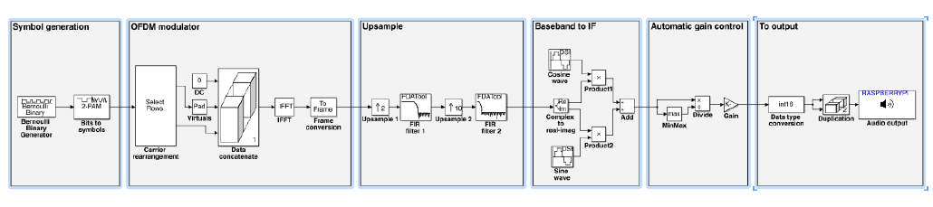
Fig. 6. Simulink model of the OFDM transmitter.
is the use of the Digilent Analog Discovery device, which
is a low cost multi-purpose instrument conceived for low
frequency applications. When connected to the PC through
the USB port, this device is able to generate and acquire
signals. With a moderate price, in the order of 270$, this
tool can operate as signal generator, oscilloscope, spectrum
analyzer, network analyzer, logic state analyzer, digital signal
generator, and power supply. The user interface of each single
instrument, displayed on the PC’s monitor, shows the same
knobs, sliders and buttons of the full hardware instrument,
allowing the user to perform the measurement activity as
if he were in a lab. Of course, the bandwidth that can be
handled by the Digilent Analog Discovery, in the order of some
MHz, cannot be compared with that of more sophisticated and
expensive instruments, however it is more than adequate for
the didactic experiences carried out with our SDR platform.
In this case, therefore, the signal generator, the oscilloscope
and the spectrum analyzer can be conveniently replaced by
this multifunction tool.
3) Additional hardware: In addition to the Raspberry Pi,
the PC hosting Simulink, and the laboratory equipments, the
hardware depicted in Fig. 2 is needed:
• Nr. 1 External sound card (Fig. 2(a)). As explained in
Section II, it is used to provide the Raspberry Pi with an
analog input, otherwise absent, and with a higher quality
analog output.
• Nr. 1 Micro SD memory card (Fig. 2(b)). It contains
the Raspberry Pi operating system.
• Nr. 1 USB to LAN adapter (Fig.2(c)). If the PC’s
Ethernet port is not available, this adapter allows to
connect the Raspberry Pi to the PC using the USB port.
• Nr. 1 USB-micro USB cable (Fig. 2(d)). It is used to
connect the Raspberry Pi to the PC’s USB port, with the
only aim to provide the power supply.
• Nr. 1 Network cable (Fig. 2(e)). It is used to connect
the Raspberry Pi to the PC.
• Nr. 2 3.5 mm-RCA jack cables (Fig. 2(f)). They are
used to connect the sound card, equipped with 3.5 mm
female jacks (Fig. 2(a)), to the instruments. RCA-BNC
adapter (Fig. 2(g)) are also needed.
• Nr. 2 RCA-BNC adapter (Fig. 2(g)). They are used to
connect the 3.5 mm-RCA jack cable to the instruments,
usually equipped with BNC connectors (Fig.2(f)).
The cost of all the additional hardware remains below 60$.
The basic workbench setup is shown in Fig. 5: one PC
hosting Simulink connected, through an Ethernet link, to the
Raspberry Pi, whose output is fed to an oscilloscope and/or
a spectrum analyzer. Some experiences also require a signal
generator, whose task is to provide the Raspberry Pi with an
external signal (such as the carrier).
B. Developed experiences
As already stated, several SDR experiences are being devel-
oped in the framework of a cooperation between Mathworks
and the University of Bologna, using the above described plat-
form. In particular, the following systems have been already
implemented:
• Signal generator;
• 2-PAM and 4-PAM baseband transmitters;
• 2-ASK and 4-ASK transmitters;
• FSK transmitter;
• Q-PSK transmitter;
• OFDM transmitter (64 and 256 carriers);
• Digital filtering;
• Adaptive noise canceler.
The corresponding Simulink models and the related documen-
tation, conceived as material to be provided to students, can
be freely downloaded at [4]. For the sake of conciseness, only
the example case of an OFDM transmitter is here presented.
V. EXAMPLE: RASPBERRY PI AS AN OFDM TRANSMITTER
To provide an example case, the Simulink model that has
been developed to implement an OFDM transmitter is shown
in Fig. 6.
2
To simplify the description, the following seven
macro-blocks have been highlighted in the figure:
1) Symbol generation: The Symbol generation macro-
block generates real symbols a
i
∈ {−1, 1}, starting from
the bits produced by the Bernoulli Binary Generator block.
Such symbols will be used to modulate the subcarriers of the
OFDM signal; as the alphabet used has just two symbols, the
modulation adopted for the subcarriers is 2-ASK. The bit rate
is set to 1800 bits/s.
2
In order to keep the model as simple as possible we did not implement
the cyclic-prefix.
2016 24th European Signal Processing Conference (EUSIPCO)
401

2) OFDM modulator: Starting from the symbols a
i
at
its input, the OFDM modulator macro-block generates the
baseband signal corresponding to an OFDM modulation with
N = 64 subcarriers, N
u
= 48 of which are actually used to
transmit modulation symbols (useful subcarriers) whereas the
remaining N
z
= 16 have null amplitude (15 virtual subcarriers
+ 1 DC subcarrier in correspondence of the frequency zero
3
).
More specifically, the N = 64 subcarriers are used as follows:
• 8 virtual subcarriers (from 1 to 8) with null amplitude;
• 24 data subcarriers (from 9 to 32) with 2-ASK modula-
tion;
• 1 DC subcarrier (number 33) with null amplitude (corre-
sponding to the zero frequency);
• 24 data subcarriers (from 34 to 57) with 2-ASK modu-
lation;
• 7 virtual subcarriers (from 58 to 64) with null amplitude.
With the introduction of the virtual and DC subcarriers, the
output sampling rate of the OFDM macro-block is 2400 sam-
ples/s. Data are organized in frames to simplify the real time
management by the hardware.
3) Upsampling: In order to modulate the baseband OFDM
signal, the sampling frequency must be increased. It is conve-
nient, on this regard, to increase it by a factor of 20, taking it
to the 48000 samples/s required by the audio card’s DAC. The
upsampling operation is performed by the sequence of blocks
included in the Upsampling macro-block, that performs an
upsampling by a factor of 2 at first and then by a factor of
10. The two stage procedure is preferable, compared with a
single stage upsampling by a factor of 20, because it reduces
the overall computational burden [6], [7].
4) Baseband to IF: The Baseband to IF macro-block mod-
ulates the signal, translating it from baseband to intermediate
frequency. Such operation is performed through a quadrature
modulator with internally generated carriers at a frequency
f
IF
= 15 kHz. The Baseband to IF macroblock is a classic
quadrature modulator, with two separate paths for the real
(in-phase) and the imaginary (quadrature) components of the
signal. Each component is upconverted by a mixer (represented
by the Product block) driven by a cosine or a sine carrier,
generated by the Cosine Wave and Sine Wave blocks. Both
modulated signals are then summed up and taken out.
5) Automatic Gain Control: The Automatic Gain Control
macro-block adapts the signal’s dynamic range to the require-
ments of the output port. As a consequence of this operation,
the highest value in each frame is equal to 2
14
− 1, consistent
with the highest value required by the output port (2
15
− 1).
6) Raspberry Pi output: The Raspberry Pi output macro-
block represents the system output port. It corresponds, there-
fore, to the sound card’s DAC.
Once the Simulink model is realized and checked through
Simulink simulations, it is possible to carry out the Deploy
to Hardware, which is triggered by Simulink itself. The
3
In order to facilitate the receiver in the research of the band center, the
subcarrier corresponding to the zero frequency (in the baseband) is usually
assigned a null amplitude. The acronym DC means Direct Current.
Fig. 7. OFDM signal spectrum.
implemented system starts as soon as the automatci download
of the corresponding software on the device is completed. Con-
necting the Raspberry Pi to the spectrum analyzer, according
to the scheme in Fig. 5, the signal spectrum appears as shown
in Fig. 7. The expected bandwidth of approximately 2 kHz
and the DC subcarrier centered at 15 kHz can be observed.
VI. CONCLUSION
Despite its popularity, the usage of Raspberry Pi boards as a
signal processing device for SDR applications is an innovative
exception and opens new possibilities to the teaching of signal
processing. Owing to its low cost, it can be massively used
in lab activities that do not require any programming skills,
thanks to the Simulink support. In the next future, even RF
transmitters and receivers could be part of the SDR platform
here presented, thank to the availability of SDR peripherals
such as the HackRF One [8] transmitter/receiver and the RTL-
SDR receiver [9].
ACKNOWLEDGMENT
The authors wish to thank Mirko Mirabella for his great
contribution to the Simulink Defined Radio project.
REFERENCES
[1] Raspberry Pi website. [Online]. Available: http://www.raspberrypi.org
[2] Raspberry Pi Academy website. [Online]. Available:
http://www.raspberrypi.org/picademy/
[3] Raspberry Pi Support from Mathworks website. [Online]. Available:
http://it.mathworks.com/hardware-support/raspberry-pi-simulink.html
[4] Raspberry pi based SDR experiences. [Online]. Available:
http://www.simulinkdefinedradio.com/
[5] Simulink and model based design. [Online]. Available:
http://it.mathworks.com/services/consulting/proven-solutions/model-
based-design.html
[6] R. Crochiere and L. Rabiner, “Interpolation and decimation of digital
signals; a tutorial review,” Proceedings of the IEEE, vol. 69, no. 3, pp.
300 – 331, March 1981.
[7] G. Pasolini and R. Soloperto, “Multistage decimators with minimum
group delay,” in IEEE International Conference on Communications
(ICC), May 2010, pp. 1–6.
[8] Hackrf One. [Online]. Available: https://greatscottgadgets.com/hackrf/
[9] RTL-SDR. [Online]. Available: http://www.nooelec.com/store/sdr/sdr-
receivers/nesdr-mini-rtl2832-r820t.html
2016 24th European Signal Processing Conference (EUSIPCO)
402
