
Page 1
MFG318258-L
Inventor Template Management Through the iLogic
API Looking Glass
Jason Hunt
FS-Elliott Co., LLC
Description
Do you find that you have too many templates to manage? Are you struggling with keeping
drawings and models up to your latest company standards? If you answered yes to any of these
questions, then this class is for you. Inventor iLogic and the API are powerful tools that can be
utilized in creating your Inventor templates, along with managing your Inventor files by keeping
them up to the latest company standards. In this class, we will create one template for multiple
drawing sheet sizes and a part template, driven by iLogic rules. We will design and create external
iLogic rules to check model standards, switch drawing styles, sheet sizes, dimension schemes,
and a few other useful tools. This class will demonstrate how the power of iLogic can help you
minimize the number of templates you need to create and maintain, along with forcing the user to
input standard company iProperties. These iLogic programs will make model and drawing setup
a breeze.
Learning Objectives
Learn how to design iLogic rules to create one drawing template for various sheet
sizes and drawing styles.
Learn how to design and create external iLogic rules to check drawing standards,
select drawing styles, as well as sheet sizes and a few other tools.
Learn how to create an Inventor iLogic rule to force CAD users to fill out required
company iProperties.
Learn about the iLogic API methods used in updating drawings to your latest
company standards.

Page 2
Speaker(s)
Jason Hunt is the NPD Group Leader in the CAD Designer Group for FS-Elliott Co., LLC. FS-
Elliott is a leading manufacturer of oil-free centrifugal air and gas compressors with sales, service,
and manufacturing locations around the world. Based in Orchard Park, NY, Jason provides lead
design services to current NPD projects and helps drives current CAD standards and Best
Practices amongst the NPD team. His experience involves 20+ years of compressor design, with
an education background in Engineering from SUNY at Alfred, Industrial Engineering from SUNY
Buffalo State and Business/Marketing from the McColl School of Business at Queens University
of Charlotte.

Page 3
Contents
Learning Objectives ................................................................................................................... 1
Speaker(s) ................................................................................................................................. 2
Class Overview .......................................................................................................................... 4
Template Introduction ................................................................................................................ 5
iLogic API Introduction ............................................................................................................... 6
Module 1 – Setting up Rules to Control Basic Drawing and Model Templates ........................... 6
Exercise 1 - General Housekeeping Steps to follow: 5 minutes .............................................. 7
Exercise 2 - iProperties Drawing Rule Creation: 5 minutes ....................................................10
Exercise 3 - Sheet Size Rule Creation: 10 minutes................................................................13
Exercise 4 - Drawing iProperties Check Rule Creation: 5 minutes .........................................17
Exercise 5 – Setting the Template Drawing iLogic Event Triggers: 5 minutes ........................19
Exercise 6 – Model Template Rule Creation: 5 minutes ........................................................20
Exercise 7 – Run the Drawing and Part Template: 5 minutes ................................................22
Module 2 – Creating External Rules to Update Drawings to the latest standards ......................26
Exercise 8 – Border Related Rules Creation: 15 minutes ......................................................26
Exercise 9 – Sheet size and Dimension Text Style Rules: 10 minutes ...................................32
Exercise 10 – Updating a drawing to the Latest Company Standards: 5 minutes ..................36
Conclusions ..............................................................................................................................41
General iLogic / API Appendix: .................................................................................................42

Page 4
Class Overview
Why is it important to manage your Inventor templates? There are many
different reasons that may drive you to manage your templates. You may
have a need to automate designs because you may be dealing with
repetitive, mundane tasks. Maybe you are finding that designers are
making too many mistakes, when modeling common components or you
may be trying to build consistency in the use of company enforced
standards. Whatever the reason for managing your templates, you need to
find a way to do it in Autodesk Inventor.
Utilizing a powerful template at the beginning of your design process can increase productivity
amongst your design teams by eliminating redundancy and improving on consistency. Templates
can also help force the team to use company standards in their designs.
Inventor iLogic and the API are powerful tools that can be utilized in creating your Inventor
templates, along with managing your Inventor files by keeping them up to the latest company
standards. In this class, we will create one template for multiple drawing sheet sizes and a part
template, driven by iLogic rules. We will design and create external iLogic rules to check drawing
standards, select drawing styles, sheet sizes, dimension schemes, and a few other useful tools.
This class will demonstrate how the power of iLogic can help you minimize the number of
templates you need to create and maintain, along with forcing the user to input standard company
iProperties. These iLogic programs will make model and drawing setup a breeze.
After the conclusion of this class, you will more than likely be thinking about your current template
workflows and how you can incorporate iLogic into them. This class will help introduce you to how
iLogic has helped my company and get you started in thinking about how to apply iLogic and API
in your company’s workflows.

Page 5
Template Introduction
Every new drawing, part or assembly file is created from an Inventor template, whether it is a
standard template or a user generated one. This class is not about how to create styles, title
blocks, or any another component that makes up a template. This class will all be about how you
can manage your template and the components that make up your template.
I recommend and believe that a custom company template is the way to go for any company that
desires to mandate certain company standards in their Inventor workflows. These templates are
stored, by default, in the following folders:
C:\Users\Public\Documents\Autodesk\Inventor (version number)\Templates
Subfolders in the Templates folder display as tabs in the Open New File dialog box.
You can create and save custom templates in the Templates folder.
You can also store these on your network and path to them in your project file.
i.e. \\Server Name\Standards\Templates\
See Figure 1 for examples of user defined templates located in a specific server location.

Page 6
iLogic API Introduction
This lab is not a deep dive into the basics of iLogic. The understanding of this lab is that the
attendee shall have a more advanced knowledge of iLogic, VB and some experience in using the
API. Although, the lab is set up so any one can learn and do the exercises at a fast pace.
With that being said, I am not going to deep dive into teaching why to use iLogic and the VB
techniques in creating iLogic code. I have a brief overview of these techniques and reasons for
using iLogic in the “General iLogic / API Appendix”, located at the end of this handout as
additional information. The focus of this class is to show a more advanced user how to utilize the
iLogic / API tools in an advanced way to manage their templates, versus teaching the basics.
Module 1 – Setting up Rules to Control Basic Drawing and Model Templates
The purpose of this exercise is to show how you can
utilize iLogic and the API to manage your drawing and
model templates.
We will do the following:
Do some general housekeeping to make sure
everyone’s computer is set up correctly for the lab.
Create external iLogic rules to drive a new drawing
template file to select a sheet size and
dimensioning scheme. We will focus only on two
sheet sizes to make it simple.
Create external iLogic rules to drive a new model (.ipt & .iam) template file to select
the model units and precision of the model dimensions.
Create external iLogic rules to generate custom company required iProperties and
force population of Key iProperties.
Set up iLogic Event Triggers for the templates
Please be aware that some of the code has already been added to the iLogic Rules,
due to time constraints. The purpose of this lab is share the code that I have written
and to explain how it works, along with the hands on experience in entering the code.

Page 7
Exercise 1 - General Housekeeping Steps to follow: 5 minutes
1. Set the project file
a. Click the “Get Started” Ribbon (See Figure 2).
b. In the “Launch” panel, click on “Projects” (See
Figure 2) and the “Projects” dialog window will
pop up.
c. Click on “Browse” (See Figure 3).
d. Browse to “C:\DATASETS\MFG318258-L Inventor Template Management
Through the iLogic API Looking Glass\Project File” (See Figure 4).
e. Select the “.ipj” file named “MFG318258-L.ipj” and push the “Open” button (See
Figure 4).
f. Push the “Done”
Button (See Figure 3).

Page 8
2. Setting the iLogic Configuration for the External Rules.
a. Click the “Tools” Ribbon and select
“iLogic Configuration” (See
Figure 5).
b. In the “Advanced iLogic Configuration”
dialog window, click on “Import” (See
Figure 6) and a Windows explorer
window will appear.
c. Browse to this location (See Figure 7):
“C:\DATASETS\MFG318258-L Inventor Template Management Through the iLogic API Looking
Glass\iLogic Configuration”
d. Select the following file “iLogicOptions - MFG318258-L.xml” and Push the
“Open” Button (See Figure 7).

Page 9
e. The “External Rule Directories” will now
appear (See Figure 8).
f. Next, push the “Security Options”
button (See Figure 8).
g. Select the All events enabled except
‘After Open’ and ‘Close’ radial button
and push the “OK” button (See Figure 9).
h. Push the “OK” button to preserve your settings (See Figure 8).
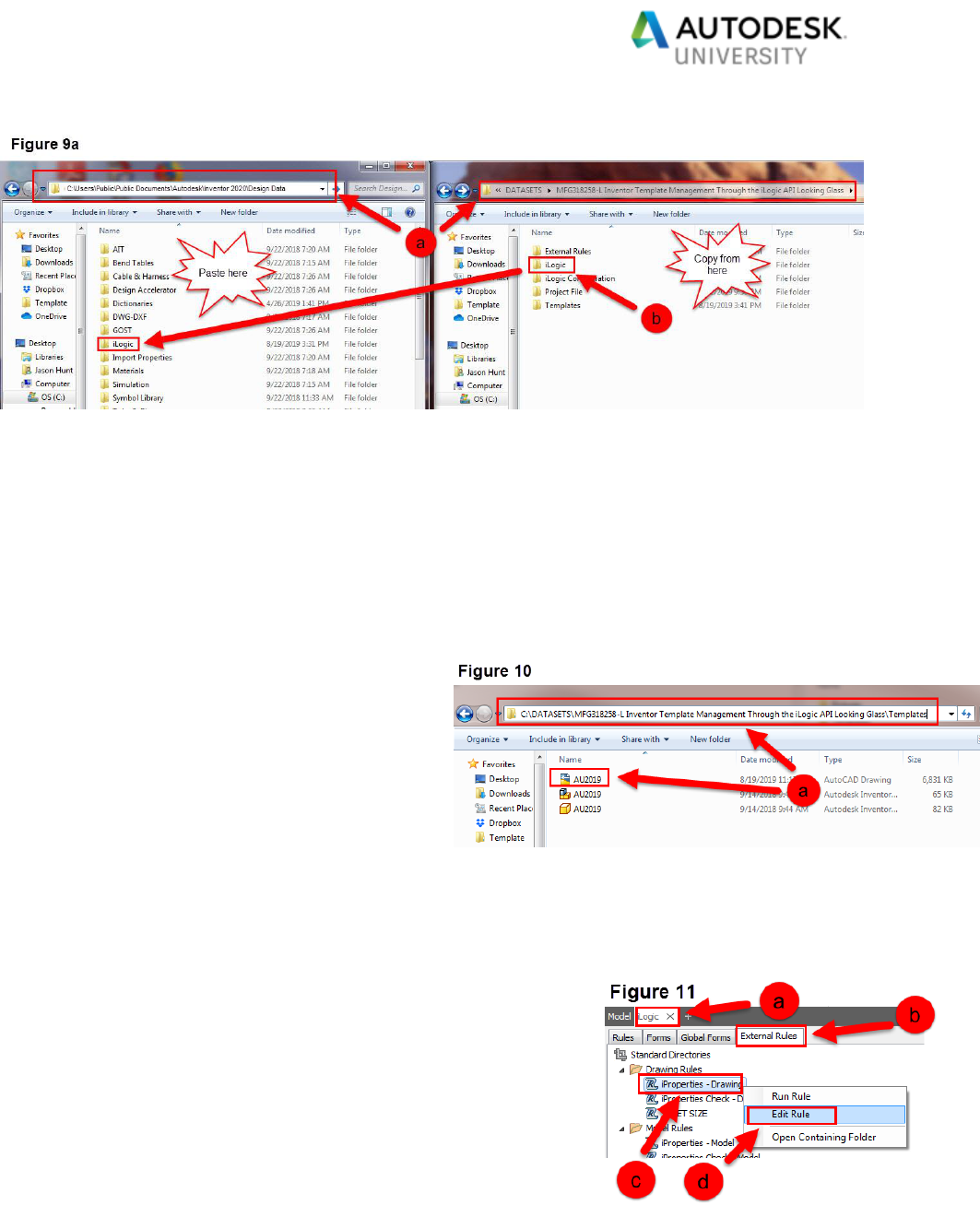
3. Moving the Global Forms to the iLogic Folder on your Computer.
a. Open two Windows Explorer windows and browse to the following two locations
(See Figure 9a):
C:\Users\Public\Public Documents\Autodesk\Inventor 2020\Design Data
C:\DATASETS\MFG318258-L Inventor Template Management Through
the iLogic API Looking Glass
b. Copy and paste the “iLogic” folder from C:\DATASETS\MFG318258-L Inventor
Template Management Through the iLogic API Looking Glass to the
C:\Users\Public\Documents\Autodesk\Inventor 2020\Design Data folder (See
Figure 9a).
c. Close the Windows explorer windows.
Page 10
Exercise 2 - iProperties Drawing Rule Creation: 5 minutes
The rule “iProperties - Drawing” that we are going to create in this section will control the creation
of the iProperties required for the drawing template.
This rule will do the following:
Will check to see if required iProperties exist in the template file.
If the iProperties do not exist, this rule will create them.
Let us get started on editing this pre-existing rule “iProperties - Drawing”.
Steps to follow:
1. With Inventor open, do the following:
a. Open up the drawing file
“AU2019.dwg”, from the following
location (See Figure 10):
C:\DATASETS\MFG318258-L Inventor Template Management Through the
iLogic API Looking Glass\Templates
2. Edit the rule “iProperties – Drawing” by doing the following:
a. Go to the “iLogic” Browser (See Figure 11).
b. Go to the “External Rules” tab (See Figure 11).
c. After expanding all the rules, right click on the
Drawing rule “iProperties Drawing” (See Figure
11).
d. Select “Edit Rule” (See Figure 11).

Page 11
3. The Edit Rule Dialog will appear and the current code is as follows (See Figure 12):
a. Enter the following “iProperty Check / Creation” code after the last line of code
in the rule (See Figure 12).
Try
prop = customPropertySet.Item(propertyName2)
Catch
customPropertySet.Add("", propertyName2)
End Try
Try
prop = customPropertySet.Item(propertyName3)
Catch
customPropertySet.Add("", propertyName3)
End Try
Try
prop = customPropertySet.Item(propertyName4)
Catch
customPropertySet.Add("", propertyName4)
End Try
Try

Page 12
prop = customPropertySet.Item(propertyName5)
Catch
customPropertySet.Add("", propertyName5)
End Try
Try
prop = customPropertySet.Item(propertyName6)
Catch
customPropertySet.Add("", propertyName6)
End Try
Try
prop = customPropertySet.Item(propertyName7)
Catch
customPropertySet.Add("", propertyName7)
End Try
Try
prop = customPropertySet.Item(propertyName8)
Catch
customPropertySet.Add("", propertyName8)
End Try
Try
prop = customPropertySet.Item(propertyName9)
Catch
customPropertySet.Add("", propertyName9)
End Try
Try
prop = customPropertySet.Item(propertyName10)
Catch
customPropertySet.Add("", propertyName10)
End Try
Try
prop = customPropertySet.Item(propertyName11)
Catch
customPropertySet.Add("", propertyName11)
End Try
Try
prop = customPropertySet.Item(propertyName12)
Catch
customPropertySet.Add("", propertyName12)
End Try
b. Push the “Save & Run” button in the “Edit Rule Dialog” box. If the code compiles
correctly the program will run and the dialog box will close on its own.
c. If any errors occur, it is more likely a typo. Do a quick review of the code to see if
you can debug it.

Page 13
d. If you are not able to debug the error, please ask one of the lab assistants to help.
e. Due to time constraints, if there are still issues with the code, you may copy and
paste the code into the Rule editor. Please refrain, as much as possible, from
copying the whole program upfront. Doing so may hinder your understanding of
the code.
4. DO NOT Save the Inventor Drawing File.
Exercise 3 - Sheet Size Rule Creation: 10 minutes
The rule “Sheet Size” that we are going to create in this section will control the drawing template
creation.
This rule will do the following:
Allow the user to select the Sheet Size
Allow the user to select the Dimension Style (Scheme)
In this rule, we are going to limit the sheet size choices to only “A0” and “A1” sheet sizes. The
borders that we will use are custom created borders located in the template file.
Let us get started on editing this pre-existing rule “Sheet Size”.
Steps to follow:
1. With the “AU2019.dwg” Inventor file still open, do the following:
2. Edit the rule “SHEET SIZE” by doing the following:
a. Go to the “iLogic” Browser (See Figure 13).
b. Go to the “External Rules” tab (See Figure 13).
c. Right Click on the Drawing rule “SHEET SIZE”
(See Figure 13).
d. Select “Edit Rule” (See Figure 13).

Page 14
3. The Edit Rule Dialog will appear
and the current code is as follows
(See Figure 14).
a. As mentioned previously,
code is already in the rule,
due to time constraints.
The code will be
explained as we go
through it and as we enter
the additional code. There
is just too much to enter
by an individual in this lab.
4. Enter the following code for counting the total number of sheets in the template files. This
is needed to assist in changing out the title block specific to the primary versus the
secondary title block.
a. Enter the code in the boxed in area of Figure 15.
i = 0
For Each osheet In oDrawing.Sheets
If osheet.ExcludeFromCount = True Then
i = i + 1
Else
End If
Next

Page 15
5. Enter the following lines of code to change the sheet 1 size and dimension scheme, based
on the user inputs from the message box.
a. Enter the code in the boxed in area of Figure 16.
'---------------------SHEET 1 A1 - METRIC
ElseIf Parameter("SHEET_SIZE") = "A1 - METRIC" Then
ActiveSheet.ChangeSize("A1", MoveBorderItems := True)
ActiveSheet.Border = "AU - A1"
ActiveSheet.TitleBlock = "AU PRIMARY"
Parameter("DIM_STYLE") = "METRIC"
'---------------------SHEET 1 A0 - INCH
ElseIf Parameter("SHEET_SIZE") = "A0 - INCH" Then
ActiveSheet.ChangeSize("A0", MoveBorderItems := True)
ActiveSheet.Border = "AU - A0"
ActiveSheet.TitleBlock = "AU PRIMARY"
Parameter("DIM_STYLE") = "INCH"
'---------------------SHEET 1 A1 - INCH
ElseIf Parameter("SHEET_SIZE") = "A1 - INCH" Then
ActiveSheet.ChangeSize("A1", MoveBorderItems := True)
ActiveSheet.Border = "AU - A1"
ActiveSheet.TitleBlock = "AU PRIMARY"
Parameter("DIM_STYLE") = "INCH"
6. Enter the following lines of code to change the sheet 1 size and dimension scheme, based
on the user inputs from the message box.
a. Enter the code in the boxed in area of Figure 17.
'---------------------SHEET 2 A1 - METRIC
ElseIf Parameter("SHEET_SIZE") = "A1 - METRIC" Then
ActiveSheet = ThisDrawing.Sheet("Sheet:"&X)

Page 16
ActiveSheet.ChangeSize("A1", MoveBorderItems := True)
ActiveSheet.Border = "AU - A1"
ActiveSheet.TitleBlock = "AU SECONDARY"
stylesMan.ActiveStandardStyle = stylesMan.StandardStyles("ANSI - FSE - MM")
'---------------------SHEET 2 A0 - INCH
ElseIf Parameter("SHEET_SIZE") = "A0 - INCH" Then
ActiveSheet = ThisDrawing.Sheet("Sheet:"&X)
ActiveSheet.ChangeSize("A0", MoveBorderItems := True)
ActiveSheet.Border = "AU - A0"
ActiveSheet.TitleBlock = "AU SECONDARY"
stylesMan.ActiveStandardStyle = stylesMan.StandardStyles("ANSI - FSE - INCH")
'---------------------SHEET 2 A1 - INCH
ElseIf Parameter("SHEET_SIZE") = "A1 - INCH" Then
ActiveSheet = ThisDrawing.Sheet("Sheet:"&X)
ActiveSheet.ChangeSize("A1", MoveBorderItems := True)
ActiveSheet.Border = "AU - A1"
ActiveSheet.TitleBlock = "AU SECONDARY"
stylesMan.ActiveStandardStyle = stylesMan.StandardStyles("ANSI - FSE - INCH")
b. Push the “Save & Run” button in the “Edit Rule Dialog” box. If the code compiles
correctly the program will run and the dialog box will close on its own.
i. When prompted, select any drawing sheet size.
ii. The drawing will now show the border per the selected sheet size.
c. If any errors occur, it is more likely a typo. Do a quick review of the code to see if
you can debug it.
d. If you are not able to debug the error, please ask one of the lab assistants to help.
e. Due to time constraints, if there are still issues with the code, you may copy and
paste the code into the Rule editor. Please refrain, as much as possible, from
copying the whole program upfront. Doing so may hinder your understanding of
the code.
f. DO NOT save the file. Close the drawing.

Page 17
Exercise 4 - Drawing iProperties Check Rule Creation: 5 minutes
The rule “iProperties Check - Drawing” that we are going to create in this section will check to
see if key iProperties are filled out. If they are not filled out, the program will force the user to
populate these iProperties.
This rule will do the following:
Check key iProperties are populated
Force key iProperty population
Let us get started on editing this pre-existing rule “iProperties Check - Drawing”.
Steps to follow:
1. Open up the drawing file “AU2019.dwg”, from the following location:
C:\DATASETS\MFG318258-L Inventor Template Management Through the
iLogic API Looking Glass\Templates
2. Edit the rule “iProperties Check - Drawing” by doing the following:
a. Go to the “iLogic” Browser (See Figure 18).
b. Go to the “External Rules” tab (See Figure 18).
c. Right Click on the Drawing rule “iProperties
Check - Drawing” (See Figure 18).
d. Select “Edit Rule” (See Figure 18).
3. The Edit Rule Dialog will appear and the current code is
as follows (See Figure 19).
4. Enter the following code for checking and forcing the population of the below mentioned
iProperties.
Description
Project
DRAWN BY
a. Enter the code in the boxed in area of Figure 19.

Page 18
If String.IsNullOrWhiteSpace(Project) = True
Do Until String.IsNullOrWhiteSpace(Project) = False
i = MessageBox.Show("Please Enter a Project.", "Project Dialog",
MessageBoxButtons.OK, MessageBoxIcon.Hand, MessageBoxDefaultButton.Button1)
iLogicForm.ShowGlobal("iProperty Check Editor", FormMode.Modal)
Desc = iProperties.Value("Project", "Description")
Project = iProperties.Value("Project", "Project")
Drawn = iProperties.Value("Custom", "DRAWN BY")
Loop
End If
If String.IsNullOrWhiteSpace(Drawn) = True
Do Until String.IsNullOrWhiteSpace(Drawn) = False
i = MessageBox.Show("Please Enter Drawn By Name.", "Project Dialog",
MessageBoxButtons.OK, MessageBoxIcon.Hand, MessageBoxDefaultButton.Button1)
iLogicForm.ShowGlobal("iProperty Check Editor", FormMode.Modal)
Desc = iProperties.Value("Project", "Description")
Project = iProperties.Value("Project", "Project")
Drawn = iProperties.Value("Custom", "DRAWN BY")
Loop
End If
b. Push the “Save & Run” button in the “Edit Rule Dialog” box. If the code compiles
correctly the program will run and the dialog box will close on its own.
i. If prompted to fill out any of the iProperties in a message window, please
do so.
c. If any errors occur, it is more likely a typo. Do a quick review of the code to see if
you can debug it.
d. If you are not able to debug the error, please ask one of the lab assistants to help.

Page 19
e. Due to time constraints, if there are still issues with the code, you may copy and
paste the code into the Rule editor. Please refrain, as much as possible, from
copying the whole program upfront. Doing so may hinder your understanding of
the code.
f. DO NOT save the file. Close the drawing.
Exercise 5 – Setting the Template Drawing iLogic Event Triggers: 5 minutes
The purpose of this exercise is to set the iLogic Event triggers for the drawing template file.
This will do the following:
Automatically run the template program, when the dwg is opened.
Automatically Force key iProperty population.
Steps to follow:
1. Open up the drawing file “AU2019.dwg”, from the following location:
C:\DATASETS\MFG318258-L Inventor Template Management Through the
iLogic API Looking Glass\Templates
2. Set the iLogic Event Triggers by doing the following:
a. Go to the “Manage” ribbon (See Figure 20).
b. Go to the “iLogic” panel (See Figure 20).
c. Click on the “Event Triggers” button (See Figure 20).

Page 20
d. The “Event Triggers” dialog will
appear. Drag the “iProperties
Check – Drawing” & “SHEET SIZE”
rule from the “Drawing Rules”
folders to the “New Document”
section in “Rules On Events” (See
Figure 21).
i. Make sure to reorganize the
“Rules On Events” to match
Figure 21, by dragging the
rules to the proper order.
e. Push the “OK” button to close the
window.
f. Save the AU2019.dwg file and
close after saving.
Exercise 6 – Model Template Rule Creation: 5 minutes
The rule “MODEL UNITS” that we are going to create in this section will control the setup of the
model, based on your standards.
This rule will do the following:
Will check to see if required iProperties exist in the template file.
If the iProperties do not exist, this rule will create them.
Allow the user to select the model units and precision of the units to display in the model.
Please note that the iLogic event triggers have already been set for this model.
Let us get started on editing this pre-existing rule “MODEL UNITS”.
Steps to follow:
1. With Inventor open, do the following:
a. Open up the model file
“AU2019.ipt”, from the following
location (See Figure 22):
C:\DATASETS\MFG318258-L Inventor Template Management Through the
iLogic API Looking Glass\Templates

Page 21
2. Please note that the following rules have already
been created, as they are very similar to ones created
for the drawing template (See Figure 23):
3. Edit the rule “MODEL UNITS” by doing the following:
a. Go to the “iLogic” Browser (See Figure 24).
b. Go to the “External Rules” tab (See Figure 24).
c. Right Click on the Drawing rule “MODEL UNITS”
(See Figure 24).
d. Select “Edit Rule” (See Figure 24).
4. The Edit Rule Dialog will appear and the current code is as
follows (See Figure 25).
5. Enter the following code for checking and forcing the population of the below mentioned
iProperties.
Description
Project
DRAWN BY

Page 22
a. Enter the code in the boxed in area of Figure 25.
Dim openDoc As Document
openDoc = ThisDoc.Document
'---------------------SET LENGTH UNITS FOR THE MODEL / ASSEMBLY
openDoc.UnitsOfMeasure.LengthUnits = oUOM_1
'---------------------SET MASS UNITS FOR THE MODEL / ASSEMBLY
openDoc.UnitsOfMeasure.MassUnits = oUOM_2
'---------------------SET PRECISION
openDoc.unitsofmeasure.LengthDisplayPrecision = oPrecision
b. Push the “Save & Run” button in the “Edit Rule Dialog” box. If the code compiles
correctly the program will run and the dialog box will close on its own.
i. When prompted, select a UOM.
ii. When prompted, select the model units display precision.
c. If any errors occur, it is more likely a typo. Do a quick review of the code to see if
you can debug it.
d. If you are not able to debug the error, please ask one of the lab assistants to help.
e. Due to time constraints, if there are still issues with the code, you may copy and
paste the code into the Rule editor. Please refrain, as much as possible, from
copying the whole program upfront. Doing so may hinder your understanding of
the code.
f. DO NOT save the file. Close the file without saving.
Exercise 7 – Run the Drawing and Part Template: 5 minutes
The templates in this exercise will automatically run as soon as you open them, due to the iLogic
Event triggers.
Templates we will work with are just the AU2019.ipt and the AU2019.dwg templates:
Steps to follow:
1. With Inventor open, do the following:
a. Go to the File Ribbon and select “New” (See Figure 26).
b. Select the “AU2019.ipt” template (See Figure 26).
d. Push the “Create” button (See Figure 26).

Page 23
2. The following window prompts will appear (See Figure 27).
a. In the “MODEL UNITS” window, select a Unit of Measure (UOM) for your model
(See Figure 27).
b. In the “MODEL UNITS” window, push the “OK” button (See Figure 27).
c. The “iLogic” window will appear next, select the UOM precision (Decimal Places)
that will appear in your model (See Figure 27).
d. In the “iLogic” Window, push the “OK” button (See Figure 27).
e. A “Description Dialog” window will appear alerting you to fill out the description,
push the “OK” button (See Figure 27).
f. Fill out the “iProperties for both Models and Drawings”, try to leave it blank or
try to cancel the form. The window will keep reappearing until you fill out the
mandatory iProperties (See Figure 27).
g. Please note that the iProperties for Drawings is not required for a model (See
Figure 27).
h. Push the “Done” button (See Figure 27).
i. You have just run the part template with success.

Page 24
3. In Inventor, do the following:
a. Go to the File Ribbon and select “New” (See Figure 26).
c. Select the “AU2019.dwg” template (See Figure 26).
d. Push the “Create” button (See Figure 26).
4. The following window prompts will appear (See Figure 28).
a. The “DRAWING SHEET SIZE” window will appear, select the desired sheet size
and dimensioning scheme (See Figure 28).
b. In the “DRAWING SHEET SIZE” window, push the “OK” button (See Figure 28).
c. A “Description Dialog” window will appear alerting you to fill out the description,
push the “OK” button (See Figure 28).
d. Fill out the all of the iProperties in the “iProperty Check Editor” form, try to leave
it blank or try to cancel the form. The window will keep reappearing until you fill out
the mandatory iProperties (See Figure 28).
e. Push the “Done” button (See Figure 28).

Page 25
f. Take note that you now have created your drawing, based on the template and
your selected sheet size and dimensioning scheme (See Figure 29).

Page 26
Module 2 – Creating External Rules to Update Drawings to the latest standards
The purpose of this exercise is to show how you
can utilize both iLogic and the API to update
drawings to your companies, latest standards.
This lab will only focus on a few key elements of
the API model objects due to time constraints.
We will do the following:
Create external iLogic rules to check if your
drawing file is per the latest company
standards.
Create external iLogic Rules to update drawing files to latest company standards.
Exercise 8 – Border Related Rules Creation: 15 minutes
The rules we will be creating will do the following:
When updating an old drawing a rule will need to be created to delete the old border.
A rule will then need to be created to add the new border.
A third rule will need to be created to incorporate the above rules by removing the old
border and add in the new border to the drawing being updated.
Steps to follow:
1. With Inventor open, do the following:
a. Go to the File Ribbon and select “New” (See Figure 30).
b. Select the “AU2019.dwg” (See Figure 30).
c. Push the “Create” button (See Figure 30).
d. Follow any system prompts and directions to open up the file.

Page 27
2. In this step, we are going to edit the rule “BORDER DELETION”. This rule will delete the
border on the drawing to be updated so the new one can be added later on. Follow
these steps to edit the rule:
a. Go to the iLogic Browser (See Figure 31).
b. Click on the “External Rules” tab (See Figure 31).
c. Right Click on the rule “BORDER DELETION”
(See Figure 31).
d. Select “Edit Rule” (See Figure 31).
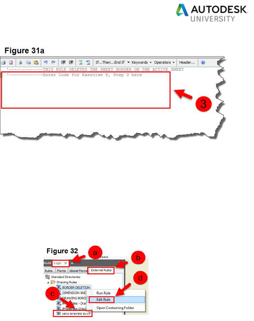
3. The Edit Rule Dialog will appear, enter the following code
into the rule:
Enter the code in the boxed in area of Figure 31a
'-------------THIS RULE DELETES THE SHEET BORDER ON THE ACTIVE SHEET
Dim oDrawDocC As DrawingDocument = ThisApplication.ActiveDocument
Dim oSheetC As Sheet = oDrawDocC.ActiveSheet
Dim oBorderC As Border = oSheetC.Border
oBorderC.Delete
Page 28
a. Push the “Save” button in the “Edit Rule Dialog” box.
b. Push the “Close” button in the “Edit Rule Dialog” Box.
4. In this step, we are going to edit the rule “NEW BORDER RULE”. This rule will copy the
borders from the Drawing template and put them in the drawing to be updated.
a. Go to the iLogic Browser (See Figure 32).
b. Click on the “External Rules” tab (See Figure 32).
c. Right Click on the rule “NEW BORDER RULE” (See Figure 32).
d. Select “Edit Rule” (See Figure 32).

Page 29
5. The Edit Rule Dialog will appear and the current code is as follows (See Figure 33).
a. Enter the code in the boxed in area of Figure 33.
Do While X <= N
ActiveSheet = ThisDrawing.Sheet("Sheet:"&X)
'-------------THIS RULE DELETES THE SHEET BORDER ON THE ACTIVE SHEET
iLogicVb.RunExternalRule("BORDER DELETION")
X = X+1
Loop
X = 1
ThisDrawing.ResourceFileName = "C:\DATASETS\MFG318258-L Inventor Template
Management Through the iLogic API Looking Glass\Templates\AU2019.dwg"
ThisDrawing.KeepExtraResources = True
ActiveSheet.Border = "AU - A1"
ActiveSheet.Border = "AU - A0"
iLogicVb.RunExternalRule("BORDER DELETION")
b. Push the “Save” button in the “Edit Rule Dialog” box.
c. Push the “Close” button in the “Edit Rule Dialog” Box.
6. In this step, we are going to edit the rule “DRAWING BORDER AND TITLE BLOCK
UPDATE”. This rule will update the border on the drawing being updated.
a. Go to the iLogic Browser (See Figure 34).
b. Click on the “External Rules” tab (See Figure 34).

Page 30
c. Right Click on the rule “DRAWING BORDER
AND TITLE BLOCK UPDATE” (See Figure
34).
d. Select “Edit Rule” (See Figure 34).
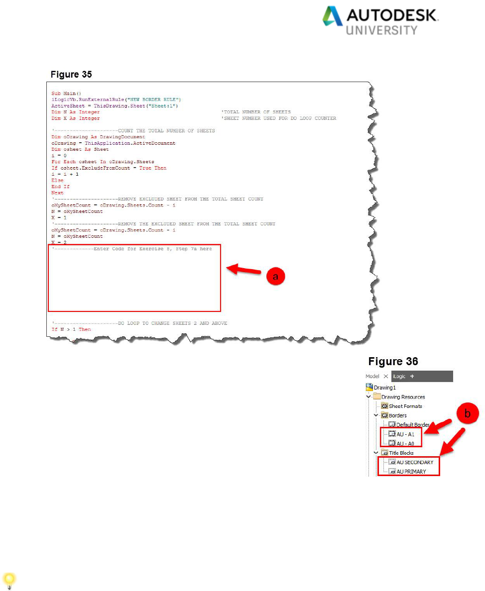
7. The Edit Rule Dialog will appear and the current code is as follows (See Figure 35).
a. Enter the code in the boxed in area of Figure 35.
'Check if the document is drawing
If ThisApplication.ActiveDocument Is Nothing Or ThisApplication.ActiveDocumentType <>
kDrawingDocumentObject Then
MsgBox ("Please open a Drawing to work on.")
Exit Sub
End If
Dim oDrawingDoc As Inventor.DrawingDocument: oDrawingDoc = ThisApplication.ActiveDocument
Dim SheetNumber As Integer
'TITLEBLOCK
'Clear out the old Titleblocks
For SheetNumber = 1 To 1
ActiveSheet = ThisDrawing.Sheet("Sheet:1")
If Not oDrawingDoc.ActiveSheet.TitleBlock Is Nothing Then
oDrawingDoc.ActiveSheet.TitleBlock.Delete
End If
Next
'Delete the previous title blocks as the API does not support replacing Sheet
Formats.
DeleteTitleBlocks (oDrawingDoc) 'CALLING SUBROUTINE
'reference template
ThisDrawing.ResourceFileName = "C:\DATASETS\MFG318258-L Inventor Template Management
Through the iLogic API Looking Glass\Templates\AU2019.dwg"
ThisDrawing.KeepExtraResources = False
ActiveSheet = ThisDrawing.Sheet("Sheet:1")
ActiveSheet.TitleBlock = "AU PRIMARY"
Page 31
b. Push the “Save & Run” button in the “Edit Rule Dialog” box.
You should see the borders disappear and the title blocks
replaced, the “Borders” and “Title Blocks” have been replaced
in the “Drawing Resources” (See Figure 36).
c. If any errors occur, it is more likely a typo. Do a quick review of
the code to see if you can debug it, otherwise follow the
prompts instructions.
d. If you are not able to debug the error, please ask one of the lab assistants to help.
e. Due to time constraints, if there are still issues with the code, you may copy and
paste the code into the Rule editor. Please refrain, as much as possible, from
copying the whole program upfront. Doing so may hinder your understanding of
the code.
f. Do not save, leave the drawing open.

Page 32
Exercise 9 – Sheet size and Dimension Text Style Rules: 10 minutes
The rules we will be creating are rules that do the following:
When updating an old drawing a rule will need to be created to select the Dimension and
text style for the drawing, this is a very large rule so we will just be doing a small portion
of it due to time constraints.
A rule will be created to select the sheet size and incorporate the “DIMENSION AND TEXT
STYLE” rule.
Steps to follow:
1. With the Inventor drawing still open, we are going to edit the rule “DIMENSION AND
TEXT STYLE”. This rule will change the styles in the drawing you are updating. Since
there is a lot of code to switch out and replace styles, we will just focus on the code for
the “Dimension Styles”. Please follow these steps:
a. Go to the iLogic Browser (See Figure 37).
b. Click on the “External Rules” tab (See Figure 37).
c. Right Click on the rule “DIMENSION AND TEXT
STYLE” (See Figure 37).
d. Select “Edit Rule” (See Figure 37).
2. The Edit Rule Dialog will appear and the current code is as follows (See Figure 38).

Page 33
3. Enter the following code in the boxed in area (See Figure 39). This code create a multi-
value parameter used in selecting the Dimension text style.
Try
oTest = Parameter("DIM_STYLE")
Catch
'---------------------MULTI-VALUE TEXT PARAMETER CREATION
ThisDoc.Document.Parameters.UserParameters.AddByValue("DIM_STYLE", "METRIC",
UnitsTypeEnum.kTextUnits)
'---------------------SET LIST
MultiValue.SetList("DIM_STYLE", "METRIC", "INCH")
End Try
Parameter.Param("DIM_STYLE").IsKey = True
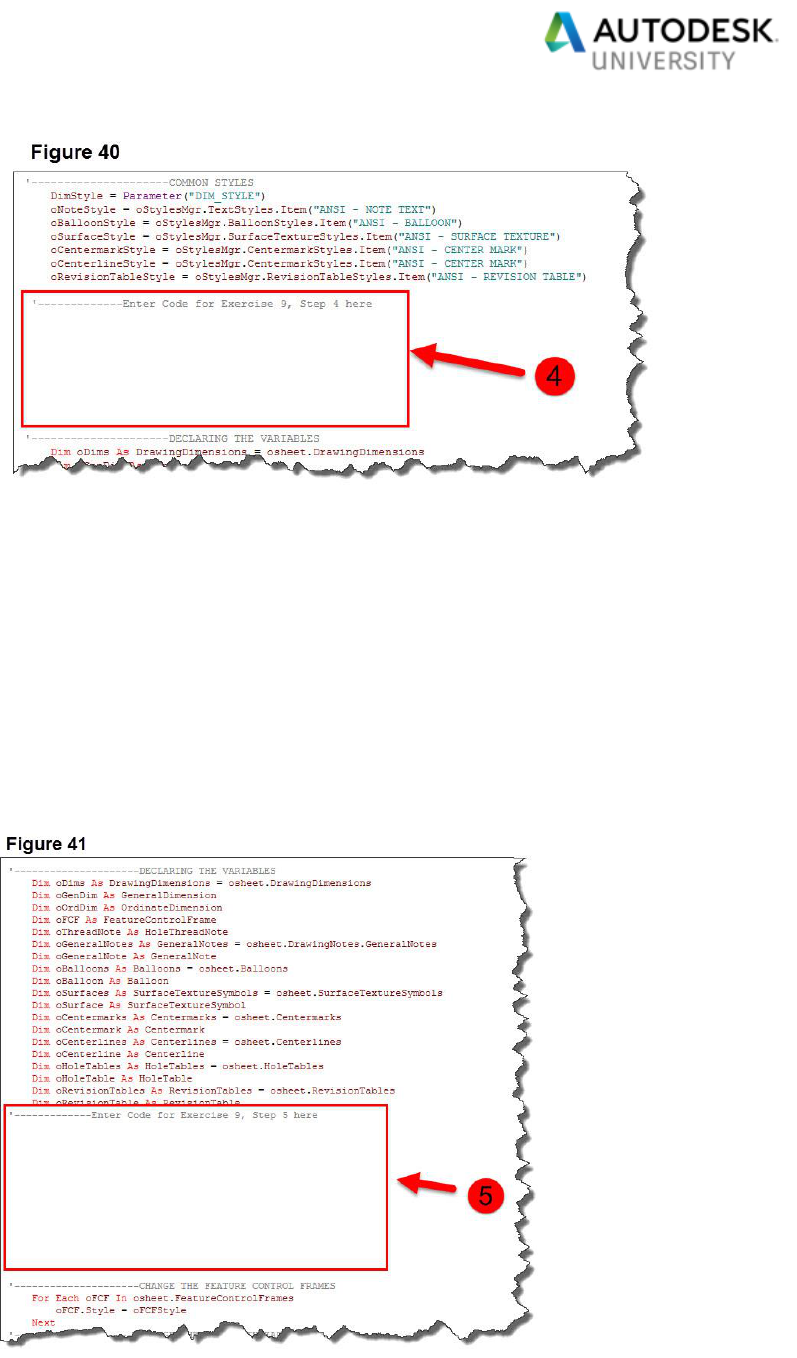
4. Enter the following code in the boxed in area (See Figure 40). This code will set the
styles to the correct ones, based on user input in another rule.
If Parameter("DIM_STYLE") = "INCH" Then
oDimStyle = oStylesMgr.DimensionStyles.Item("ANSI - IN [MM]")
oDimStyle2 = oStylesMgr.DimensionStyles.Item("ANSI - ORDINATE - IN [MM]")
oFCFStyle = oStylesMgr.FeatureControlFrameStyles.Item("ANSI - FCF - INCH")
oStylesMgr.ActiveStandardStyle = oStylesMgr.StandardStyles.Item("ANSI - FSE - INCH")
oHoleTableStyle = oStylesMgr.HoleTableStyles.Item("ANSI - HOLE TABLE (INCH)")
ElseIf Parameter("DIM_STYLE") = "METRIC" Then
oDimStyle = oStylesMgr.DimensionStyles.Item("ANSI - MM")
oDimStyle2 = oStylesMgr.DimensionStyles.Item("ANSI - ORDINATE - MM")
oFCFStyle = oStylesMgr.FeatureControlFrameStyles.Item("ANSI - FCF - MM")
oStylesMgr.ActiveStandardStyle = oStylesMgr.StandardStyles.Item("ANSI - FSE - MM")
oHoleTableStyle = oStylesMgr.HoleTableStyles.Item("ANSI - HOLE TABLE (MM)")
End If
Page 34
5. Enter the following code to change out both the general dimensions and the ordinate
dimensions on the drawings to match the new style, in the boxed in area (See Figure
41).
'---------------------CHANGE THE GENERAL DIMENSIONS
For Each oGenDim In oDims.GeneralDimensions
oGenDim.Style = oDimStyle
Next
'---------------------CHANGE THE ORDINATE DIMENSIONS
For Each oOrdDim In oDims.OrdinateDimensions
oOrdDim.Style = oDimStyle2
Next

Page 35
a. Push the “Save” button in the “Edit Rule Dialog” box.
b. Push the “Close” button in the “Edit Rule Dialog” Box.
6. With the Inventor drawing still open, we are going to edit the rule “SHEET SIZE AND
DIM TEXT STYLE”. This rule will check for the following items to see if an update is
warranted. A message window will pop up and let the user know either way.
Drawing Borders
Sheet Size
Dimension Text Styles
iProperties
a. Go to the iLogic Browser (See Figure 42).
b. Click on the “External Rules” tab (See
Figure 42).
c. Right Click on the rule “SHEET SIZE AND
DIM TEXT STYLE” (See Figure 42).
d. Select “Edit Rule” (See Figure 42).
7. The Edit Rule Dialog will appear and the current code is as follows (See Figure 43).

Page 36
8. In this last bit of code, we are going to add in the check to see if the
“Dimension text Style” is to the latest standards. Add the following
code in the boxed in area (See Figure 44).
If iProperties.Value("Custom", "DIMENSION TEXT STYLE REVISION") = Z Then
MessageBox.Show("NO UPDATE REQUIRED. YOUR DRAWING STYLES ARE TO THE
LATEST AUTODESK UNIVERSITY STANDARDS", "UPDATE STATUS")
Else
iProperties.Value("Custom", "DIMENSION TEXT STYLE REVISION") = Z
iLogicVb.RunExternalRule("DIMENSION AND TEXT STYLE")
MessageBox.Show("YOUR DRAWING STYLES HAVE BEEN UPDATED TO THE LATEST
AUTODESK UNIVERSITY STANDARDS", "UPDATE STATUS")
End If
a. Push the “Save” button in the “Edit Rule Dialog” box.
b. Push the “Close” button in the “Edit Rule Dialog” Box.
c. DO NOT SAVE the drawing file. Close the Inventor drawing file without saving.
Exercise 10 – Updating a drawing to the Latest Company Standards: 5 minutes
We will be testing out the new rules to update the drawing “25000.dwg” to the latest
standards, with a predefined Global form.
This will test out the rules, if you have any errors, don’t worry this will be demonstrated in
class and you will have the final correct code in your datasets.

Page 37
Steps to follow:
1. Open up drawing “25000.dwg” from the following location (See Figure 45):
C:\DATASETS\MFG318258-L Inventor Template Management Through the iLogic
API Looking Glass\Example
2. The drawing is a simple Indicator Plate (See Figure 46), that has Obsolete Borders,
Obsolete Title Blocks and out of date iProperties to meet our AU 2019 standards. See
Figure 47, to see the following:
a. Obsolete Borders (See Figure 47).
b. Obsolete Title Blocks (See Figure 47).
c. Out of Date iProperties (See Figure 47).

Page 38
3. Let’s update the drawing to the latest AU 2019 standards:
a. Go to the iLogic Browser (See Figure 48).
b. Click on the “Global Forms” tab (See Figure 48).
c. Click on the “Drawing Manipulation Tools” form (See Figure 48).
If the Global forms do not show up, right click in the white space area of
the “iLogic Global Forms” tab and select “Refresh” (See Figure 48a).
d. The “Drawing Manipulation Tools”
form will appear, step one is to make
sure that all your sheets have the
proper name “Sheet” (See Figure
48).
You do not need to do this
step, it is already set up
properly.
e. Go to Step 2 and push the “Update
Drawing to the Latest AU
Standards” button (See Figure 48).

Page 39
4. The following prompts will appear as a result of starting the program:
a. The first step in the program is to
update your Border to the Latest
Autodesk University Standards. Once
this window appears, push the “OK”
button (See Figure 49).
b. The next prompt to appear will ask you to select the
sheet size. Since we did have a “D-Size” sheet
previously, the metric equivalent is an “A1”. Select the
“A1-INCH” size and push the “OK” button (See Figure
50).
c. Next a prompt will appear to let you know the sheet
size has been updated to the latest standards (See
Figure 51); push the “OK” button.
d. The next prompt will let you know your
drawing styles have been updated to
the latest standards (See Figure 52);
push the “OK” button.
e. The last prompt will let you know your
drawing iProperties have been
updated to the latest standards (See
Figure 53); push the “OK” button.

Page 40
5. Now that your drawing has been updated to the latest standards, let us go to the model
tree and see the updates (See Figure 54).
a. Take note of the new “AU” borders that have been added to the drawing (See
Figure 54).
b. Take note of the new “AU”
Title Blocks that have been
added to the drawing (See
Figure 54).
c. Take note that on Sheet 1 the
Border and title block have
been set (See Figure 54).
d. Take note that the “A1” sheet
size has been set (See
Figure 54).
e. Edit the iProperties of the
drawing to see that the new
iProperties have been added
(See Figure 55).
6. Lastly, try to run the update program again.
Take Note that the program informs you
that the drawing is up to date and no
updates are required.

Page 41
Conclusions
There are a number of ways to create code to drive intelligent templates within Inventor 2020.
What we have explored is the basic API I have used to drive template creation and file
maintenance. Please be aware that what I have shown you in this lab is only the tip of the iceberg,
in terms of what can be accomplished in utilizing the iLogic API to drive template creation and
maintenance of older CAD files. The key to deciding in the iLogic rules needed to drive your
company standards is to understand your objectives. Each iLogic Rule has its own driving factor/s
to push you towards using them. I like to break it down to using iLogic as follows:
4 Pillars of why to use iLogic
Automation:
Automation allows your design and engineering team to focus
on design activities that are not easily automated.
Efficiency:
iLogic can help you become efficient in various aspects of our
designs.
Consistency:
Using iLogic can help your company design components in a
consistent manner.
Accuracy:
iLogic gives you the opportunity to create very accurate designs
Please start thinking about your current Inventor template workflows and how you can incorporate
iLogic into them. This class has helped introduce you to how iLogic has helped my company and
get you started in thinking about how to apply iLogic and API in your company’s workflows.
My last piece of advice to you all is to stay current with best practice tips and tricks by reading
blogs, articles on-line, and magazines. Also, be sure to stay current with:
Autodesk Websites / Forums:
Autodesk Community Forums: https://forums.autodesk.com/
Autodesk Exchange Apps: https://apps.exchange.autodesk.com/en
Inventor Blogs:
From the Trenches with Autodesk Inventor (Curtis Waguespack):
http://inventortrenches.blogspot.com/
The CAD Setter Out (Paul Munford):
https://cadsetterout.com/

Page 42
General iLogic / API Appendix:
How to use iLogic in Design
Here is the main criteria to look for, when you are thinking about using iLogic in your design
process.
iLogic Usage Criteria
Repetitive tasks:
Search for repetitive tasks that you do on a regular basis that are pretty standard and
straightforward. These types of tasks may be as simple as a design check rule or something more
advanced, such as a rule checking for adherence to company standards.
Automate Complex Tasks:
Search for repetitive tasks that you do on a regular basis that are more complex in nature,
requiring a lot of thought.
Tool Creation:
Search for opportunities for tool creation. These tools can be as simple as an iLogic Rule to
populate a part weight in your drawing notes to a design tool for O-ring design.
Why use iLogic in Design
4 Pillars of why to use iLogic
Automation:
Automation allows your design and engineering team to
focus on design activities that are not easily automated.
Efficiency:
iLogic can help you become efficient in various aspects of
our designs.
Consistency:
Using iLogic can help your company design components in
a consistent manner. Doing this can assist in making your
internal workflows and your suppliers workflows easy to
determine. Producing designs in a consistent manner makes
it easier to document an efficient workflow much easier.
Accuracy:
iLogic gives you the opportunity to create very accurate designs. iLogic allows a user to create
complex designs that were once modeled in various different ways and the output data varied by
the user, into a common consistent workflow.

Page 43
Basic Overview of the 2019 Inventor iLogic Browser
What is iLogic?
iLogic enables rule driven design that
provides a simple way to capture and
reuse your work. It allows the user to
standardize and automate the design
process.
iLogic allows you to become a coding
expert without having to learn much
actual code.
In order to turn on your iLogic
browser you need to go to the
model tree and select the “+”
(show tabs button) and select
“iLogic”.
The iLogic browser will then
appear next to the model tree
browser.
What are iLogic Rules?
A rule is a small Visual Basic program that can monitor and control other Inventor
parameters, features, or components.
iLogic embeds rules as objects directly into a part, assembly and drawing documents. The
rules determine and drive the design parameter and attribute values. By controlling these
values, you can define the behavior of model attributes, features and components.
Knowledge is saved and stored directly in documents just like geometric design elements
are stored.

Page 44
Internal Rules
iLogic Rules saved within a document are known as Internal
Rules.
To create an internal iLogic rule go to the iLogic
browser and click on the “Rules” tab.
Next, right click in the open space and select “Add
Rule” from the pop-up window.
When to use Internal Rules
The iLogic rule is only going to apply to one part and not globally.
For example, if you have a part that can be any diameter, but can’t exceed the
maximum or minimum diameter due to material availability. You could write an
internal iLogic rule to flag the user.
An advantage to an internal rule is that it is copied with the part and will always remain
with the part, no matter where that part is used.
A big disadvantage is that if you need to edit or correct the code, you will have to track
down every copy of that part to perform the edits. This can be time consuming.
It is up to the designer to decide if an internal iLogic rule is the best approach.
External Rules
External Rules are saved on your local or network
drive.
To create an external iLogic rule go to the
iLogic browser and click on the “External
Rules” tab.
Next, right click in the open space and
select “Add External Rule” from the pop-up
window.
iLogic will look for Rules in the following
places:
o The folder in which the current Inventor document is located.
o The current Inventor Project Workspace folder.
o The list of folders set in iLogic Configuration.

Page 45
Next, you will have to select the
External Rule and run it.
If you plan on sharing your Rules with others in
your company, it is a good idea to add your
company iLogic folder to the list of folders in the
iLogic configuration setup.
To do this, go to “Tools > Options > iLogic
Configuration”
A pop up window will appear so you can add your
company iLogic Folder to the set up.
When to Use External Rules
External Rules are great to use when one wishes to
apply the rule to many models.
For example, if you have a company
requirement that all panels will have set
choices for material thickness, length, width,
height and color. Then you could write an
external iLogic rule to drive these choices
through all the panels.
One advantage, in this case, is that any errors in your code can be fixed in the one source
file and will automatically be applied, every time they are called in a document versus
going into every model that has the rule embedded in it.
Tip: External rules are great for creating iLogic code ‘Modules’ that you can reuse for other
tasks.
The only disadvantage is that you will need to remember to send your iLogic file with the
document, if you want the iLogic Rule to be used elsewhere.

Page 46
Best Practices for Writing iLogic Rules
Use comments in your code to make it easier to understand what your code is
doing. This will help you and others down the road to understand how it works.
Don’t overdo it by overcomplicating your rule. Sometimes more rules are better
than putting all your iLogic code into one rule.
Consider making your rules, so they can be reused in other projects. Why reinvent
the wheel.
When writing code, it is always good to be consistent in your methods.
Did I mention to use comments?
iLogic Code Snippets
Code snippets provide the programmer shortcuts, for frequently used
pieces of code. Using snippets allows the user to insert them into your
code that you would normally have to type in manually. Using snippets
also helps reduce the possibility of errors in your program, due to
typographical errors.
You can access the available snippets from the “Snippets” area of the
Edit Rule dialog box. This area features two tabs:
The System tab includes a set of predefined snippets, arranged
by category.
o In order to display the tool tip, hold the cursor over each
snippet to display its function in more detail.
The Custom tab allows you to add your own snippets, or create
custom copies of System snippets.
Favorite snippets
o Favorites allow you to choose which snippets appear
on the System tab. You can mark specific snippets as
favorites, and then toggle the display of the list to show
only those snippets marked as favorites.
Inventor API:
What is API?
API is a three-letter acronym meaning, Application Programming Interface. So, what is
API? API is an interface that allows the user write a program that will perform the same
types of operations that would normally be able to use when working in inventor
interactively.

Page 47
The use of API is important, because it allows the user to add functionality to meet their
needs. This allows the user to optimize repetitive operations in their designs, as we will
demonstrate in our live demonstrations in automating our diffuser and impeller designs.
How do I access API?
There are many different ways to access the API (VBA, Add-
Ins, Standalone EXE and Apprentice Server). None of the
methods is incorrect, so it is good to have a general
understanding of the ways to connect to the API. Having this
basic understanding will allow you to make the best decision
about how to write your program. The diagram shown to the
right, from the Inventor API Help site, illustrates the different
ways to access Inventor’s API.
In order to understand the API and to get an overview of the
methods to access API, you can view Inventor’s API help
document.
Accessing API Help
In order to access Autodesk Inventor’s API help, you need to do the following.
Go to the Help icon in the upper right hand corner of Inventor and select the drop
down arrow.
Select “Help” and go to “Programming/API Help”
A help window will appear with many API related topics.
This is a great reference
document to assist you in
programing with the API. This
document helps you develop
code by showing you how to
access Inventor functions and
some examples, so you can
use them in your code.

Page 48
VB Programing Techniques
Using “If “and “Else” Statements
What is an “If” Statement”?
An “If Statement” is a very powerful coding tool.
An “If Statement” is typically used to check some logical
statement and then execute some section of code, if the
logical statement is true.
An “If Statement” has the following syntax:
If a > b Then
'Do Something Here
End If
In the above statement if “a” is greater than “b”, some
code will be executed. If “a” is not greater than “b”, then nothing will happen and the code
will continue.
Another version of this is an “If-Else” Statement which has
the following syntax:
If a > b Then
'Do Something Here
Else
'Do Something Else Here
End If
In this example, the code will still execute the first part if “a”
is greater than “b”. However, if “a” is not greater than “b”,
some other code will be executed. Code is executed either
way, depending on the values of “a” and “b”. The “Else”
statement can also be an “ElseIf” which can contain
additional logical checks.

Page 49
Using “For Next” Loops & “Try-Catch” Statements
What is a “For Next” Loop ?
The “For Next Loop” is one of the most
frequently used loops in VBA.
The “For Next Loop” is typically used to move
sequentially through a list of items and
numbers. Let us take a closer look at this loop.
The “For Next Loop” has the following syntax:
For a_counter = start_counter To
end_counter
'Do Something Here
Next a_counter
What we are doing here is creating a loop that
uses a variable a_counter as the “time keeper”
of the loop. We set it to a value equal to start_counter at the beginning of the loop and
then increment it by 1 during each loop. The loop will execute until the time the value of
the a_counter becomes equal to the end_counter. The loop executes for the last time
when both the values match and then stop.
What is a “Try-Catch” Statement?
The “Try-Catch” statement consists of a try block
followed by one or more catch clauses, which
specify handlers for different exceptions.
In the following code example, we see both a “For
Next” loop and a “Try-Catch” statement. The code
is doing the following:
The “For Next” loop iterates through all 29 user
parameter scenarios to allow the “Try-Catch”
statement to check if the user parameter has
been created. If it hasn’t been created the user
parameter will be created through the code.
The code will check to see if the 29 user
parameters (R1, R2, R3,………R28, R29) have
been created, using the try block.
If an error exists from the Try block (the user parameter doesn’t exist) then the Catch
clause will create the user parameter.

Page 50
Example of a “For Next Loop” with a “Try-Catch” Statement:
'-----------------SHORTENS THE AMOUNT OF TEXT TO TYPE WHEN CREATING PARAMETER CODE
oMyParameter=ThisApplication.ActiveDocument.ComponentDefinition.Parameters.UserParameters
'-----------------FOR STATEMENT TO GENEREATE ALL THE PARAMETERS
For Y = 1 To 29
'---------------------R DATA POINT PARAMETER CHECK
Try
oTest1 = Parameter(“R” & Y)
Catch
'---------------------SETTING UP R DATA POINT USER PARAMETERS AS MILLIMETERS
oParameter=oMyParameter.AddByExpression(R & Y, "0", UnitsTypeEnum.kMillimeterLengthUnits)
End Try
'-----------------INCREMENTS THE DATA POINT PARAMETERS FOR Z & R
Next
The output of the above code would be to create 29 user parameters:
Parameters named as follows: R1, R2, R3, R4, R5, ………. R28, R29
The unit of measure would be in millimeters.
Using “Do While” Loops
What is a “Do While” Loop?
The “Do While Loop” provides a way to
continue iterating through your code,
while one or more conditions are true.
For Example: A “Do While Loop” can have
one or more conditions in its expression.
In the below example, there is one
condition that continues iterating while the
Variable “X” is from 1 to less than or equal
to 5. The below code will launch a
message box stating what the current X
value is, as long as the condition of X is
from 1 to less than or equal to 5 is met.

Page 51
Dim X As Integer
X = 1
Do While X <= 5
MessageBox.Show("The value of X = " &X, "X-VALUE")
X = X+1
Loop
The downside to this type of loop is that it can easily lead to infinite
loops if you are not careful. My suggestion would be to make sure
you save your file before executing your rule, or you may end up
killing your session before a save and chance losing a lot of work.
Using Spreadsheets to Assist in Writing Code
Why Use Spreadsheets?
Using a spreadsheet in the engineering world is nothing new, this practice has been
around at least since Microsoft® Excel has been around. I know from experience that it is
common practice to use a spreadsheet to store design data and to use it to calculate
engineering data outputs.
Using iLogic with spreadsheets has advantages:
Data can be read from Excel to push to Inventor
Data can be pushed to Excel to allow the spreadsheet to process the inputted data
Excel can process data and uses various functions within the spreadsheet that would
normally be rather difficult to code, using iLogic. This is an advantage to the novice
programmer.
Allows data inputs and outputs to be entered and read in a consistent manner.
You can read and input data from any sheet within the spreadsheet.
These advantages allow the user to use Microsoft Excel to define your design intent when
you are creating something as simple as door panels to something more advanced, like
an impeller. The only thing a user needs to understand is how to read and manipulate the
data from Excel and incorporate it within the iLogic program to produce the desired result.
In order to learn more about Excel iLogic functions, follow the Autodesk link below.
iLogic Excel Functions

Page 52
Methods to Specify the Excel Spreadsheet:
There are three methods to specify the Microsoft Excel data. You can embed the file
internally to the inventor file, link it to an Autodesk Inventor file, or use it as an external
file. They all will work the same way. It is just a matter of deciding what works best for your
design intent. The only slight difference is the code used to read and write data to and
from the Excel spreadsheet. These functions require either a filename or a specification
of a linked or embedded Excel file.
The supported filename extensions for Excel spreadsheets are as follows:
.xls
.xlsx
.xlsm
.xlsb

Page 53
Embedded Spreadsheets (Method 1)
There are two ways to embed a spreadsheet with an Inventor file.
Parameter Icon Method:
In order to embed the spreadsheet into your inventor file you will need to do the following.
A. Click on the Parameter icon.
B. Press the “Link” button.
C. Select the “Embed” radial button.
D. Browse to the desired Excel file.
E. Push the “Open” button.
The result is found in the “3rd Party” (found in the model tree)
with the file called “Embedding 2”.
Please note that the Embedding number at the end of
the filename can vary.
Ribbon Panel Method:
A. Go to the Manage tab and Insert panel.
B. Press the “Insert Object” button.
C. Browse to the desired Excel file.
D. Do not select the “Link” check box.
E. Push the “OK” button.

Page 54
The result is found in the “3
rd
Party” (found in the model tree) with the file called
“Embedding 2”.
Please note that the Embedding number at the
end of the filename can vary.
Special Notes:
If you use an embedded table, embed it using Link on the Parameters dialog
box. Do not change the embedded table name from the default name given to
it by Autodesk Inventor (for example, Embedding 1). G oExcel requires the
original name.
The syntax to use for writing code for an embedded spreadsheet is
“3rd Party:Embedding#” for embedded spreadsheets.
o GoExcel.CellValue("3rd Party:Embedding 1", "Sheet1", "A2")

Page 55
Linked Spreadsheets (Method 2)
There are two methods to link a spreadsheet with an Inventor file.
Parameter Icon Method:
In order to link the spreadsheet into your inventor file you will need to do the following.
A. Click on the Parameter icon.
B. Press the “Link” button.
C. Select the “Link” radial button.
D. Browse to the desired Excel file.
E. Push the “Open” button.
The result is found in the “3
rd
Party” (found in the model tree) with the file called, for this
example, “Impeller Data.xlsx”.

Page 56
Ribbon Panel Method:
A. Go to the Manage tab and Insert panel.
B. Press the “Insert Object” button.
C. Browse to the desired Excel file.
D. Select the “Link” check box.
E. Push the “OK” button.
The result is found in the “3
rd
Party” (found in the
model tree) with the file called, for this example,
“Impeller Data.xlsx”.
Special Notes:
The syntax to use for writing code for a linked spreadsheet is “3rd
Party:LinkedName.xls” for linked spreadsheets.
o GoExcel.CellValue("3rdParty:filename.xls", "Sheet1", "A2")

Page 57
Specify the name that displays in the Autodesk Inventor Model tree, under 3rd
Party.
External Path (Method 3)
Another option for reading data into iLogic program is to link the spreadsheet to the
inventor file by writing code to specify the path to the Excel file. For a filename, you can
either specify a relative or absolute path.
Relative Path:
If you do not specify a path, iLogic assumes that the Excel document is in the same
folder as the current Inventor document. A relative path is assumed to be in the
same folder as the Inventor file. iLogic also searches for the file under the project
Workspace path. You can use a relative path under the project Workspace path.
The syntax to use for writing code for a spreadsheet that utilizes a Relative
Path is:
o GoExcel.CellValue("filename.xls", "Sheet1", "A2")
Absolute Path:
An absolute path is entered in the iLogic code to read data directly from the
spreadsheet file location. Although, using an absolute path can make it difficult to
send the model to another user on another computer or if the file moves it could
make all your code invalid.
The syntax to use for writing code for a spreadsheet that utilizes an
Absolute Path is:
o GoExcel.CellValue("C:\BOMs\filename.xls", "Sheet1", "A2")
There are ways to write code to make the path a parameter. This will allow you to update
the code quickly, if the path changes. Even better, you could write code to browse for the
file location and once you select the file; the parameter for the path will update the code.
An example of this will be shown later.
Parameter Creation Using the API
Some API expressions to create parameters are as follows:
The following code snippet allows any parameter creation code to be simpler and more
compact, with the same outcome. Writing this expression will save typing time and this code
snippet only needs to be defined once in your code.
'-----------------SHORTENS THE AMOUNT OF TEXT TO TYPE WHEN CREATING PARAMETER CODE
oMyParameter=ThisApplication.ActiveDocument.ComponentDefinition.Parameters.UserParameters

Page 58
The following lines of code create user parameters and their associated values.
o The boxed in area by “A” is the parameter name "UNITLESS", with a value of
“0”.
o The boxed in area by “B” is the value "TEST” for user parameter "TEXT".
'---------------------CREATE A UNITLESS PARAMETER
oParameter=oMyParameter.AddByExpression("UNITLESS", 0, "ul")
'---------------------CREATE A USER DEFINED TEXT PARAMETER
oParameter=oMyParameter.AddByValue("TEXT", "TEST", UnitsTypeEnum.kTextUnits)
'---------------------CREATE A USER DEFINED PARAMETER WITH MILLIMETER UNITS
oParameter=oMyParameter.AddByExpression("MM", "0", UnitsTypeEnum.kMillimeterLengthUnits)
'---------------------CREATE A USER DEFINED PARAMETER WITH INCH UNITS
oParameter=oMyParameter.AddByExpression("IN", "0", UnitsTypeEnum.kInchLengthUnits)
'---------------------CREATE A USER DEFINED ANGLE PARAMETER
oParameter=oMyParameter.AddByExpression("ANGLE", "0", UnitsTypeEnum.kDefaultDisplayAngleUnits)

Page 59
API Coding (Examples / Tips & Tricks)
Before getting started with the API functionality, it can be incredibly helpful to review the API help
section from within Inventor that was introduced previously. This help section includes the API
User’s Manual, which includes helpful instructions on how to utilize various aspects of the API. It
includes the API Reference Manual, which includes all of the API Objects and their associated
properties, as well as the available Enumerators, which are used to define aspects of certain
objects. Finally, the help includes several Sample Programs that show real examples of uses for
the API with the code in VBA. The API Object Model shown above is also a helpful reference and
can be found in the help or online.
The API commands can be accessed in a number of ways including using the VBA editor built
into Inventor, or by creating an add-in or standalone .exe in something like VB.NET. The API
commands can also be accessed through the iLogic Rule editor, which can be convenient for
embedding rules within a part or assembly file or for creating external rules that can be shared
across files. In the 2020 release of Inventor, the rule editor contains helpful tool tips when typing
API expressions. For further ease of use, forms can be created within the iLogic browser with
click buttons to run rules and user fields to edit parameters.
Here is the link to the Inventor 2020 API Object Model file: Inventor 2020 Object File
