


INTRODUCTION 35
2 Sketching, Constraining,
and Dimensioning
INTRODUCTION
Most 3D parts in Autodesk Inventor start from a 2D sketch. This chapter rst provides a look at the application
options for creating a part le and sketching. It then covers the three steps in creating a 2D parametric sketch:
sketching a rough 2D outline of a part, applying geometric constraints, and then adding parametric dimensions.
Lastly, you learn how to use 2D AutoCAD data in a sketch.
OBJECTIVES
After completing this chapter, you will be able to do the following:
Change the part and sketch Application Options to meet your needs
Sketch an outline of a part
Create geometric constraints to a sketch to control design intent
Use construction geometry to help constrain a sketch
Dimension a sketch
Change a dimension’s value in a sketch
Insert AutoCAD DWG data into a part’s sketch

36 Chapter 2 SKETCHING, CONSTRAINING, AND DIMENSIONING
PART AND SKETCH APPLICATION OPTIONS
Before you start a new part, examine the part and sketch options in Autodesk Inventor that will aect how the
part le will be created and how the sketching environment will look and act. While learning Autodesk Inventor,
refer to these option settings to determine which ones work best for you—there are no right or wrong settings.
Part Options
You can customize Inventor Part options to your preferences. Click the File tab > Options button, and click on
the Part tab, as shown in the following image. Descriptions of a couple of the most common Part options follow.
For more information about the Application Options consult the help system. These settings are global—they
will aect all active and new Inventor documents.
Figure 2.1
A common option that you may want to change is the rst option: Sketch on New Part Creation. This option
controls if and how a sketch is created when a part le is created.
No new sketch
When checked, Inventor does not set a sketch plane when you create a new part (this is the default setting).
Sketch on x-y plane
When checked, Inventor sets the x-y plane as the current sketch plane when you create a new part.
Sketch on y-z plane
When checked, Inventor sets the y-z plane as the current sketch plane when you create a new part.
Sketch on x-z plane
When checked, Inventor sets the x-z plane as the current sketch plane when you create a new part.

PART AND SKETCH APPLICATION OPTIONS 37
Sketch Options
Autodesk Inventor sketching options can be customized to your preferences. Click File tab > Options, and then
click on the Sketch tab as shown in the following image. Descriptions of the most common Sketch options fol-
low. For more information about the Application Options consult the help system. These settings are global and
aect active and new Inventor documents.
Figure 2.2
Following are descriptions of the common settings that you may want to change.
Constraint Settings
Click the Settings button to control how sketch constraints and dimensions behave.
Display
Grid lines
Toggles both minor and major grid lines on the screen on and o. To set the grid distance, click the Tools tab
> Options panel > Document Settings command, and on the Sketch tab of the Document Settings dialog box,
change the Snap Spacing and Grid Display.
38 Chapter 2 SKETCHING, CONSTRAINING, AND DIMENSIONING
Minor grid lines
Toggles the minor grid lines displayed on the screen on and o.
Axes
Toggles the lines that represent the X and Y-axis of the current sketch on and o.
Coordinate system indicator
Toggles the icon on and o that represents the X-, Y-, and Z-axes at the 0, 0, 0 coordinates of the current sketch.
Snap to Grid
When checked, endpoints of sketched objects snap to the intersections of the grid as the cursor moves over them.
Autoproject edges during curve creation
When checked and while sketching, place the cursor over an object and it will be projected onto the current
sketch. You can also toggle Autoproject on and o while sketching by right-clicking and selecting Autoproject
from the menu.
Autoproject edges for sketch creation and edit
When checked, and when a new sketch is created or edited, all the edges that dene the plane are automatically
projected as reference geometry.
Project objects as construction geometry
When checked, automatically projects selected geometry as construction geometry.
Look at sketch plane on sketch creation and edit
When checked, automatically changes the view orientation to look directly at the new or active sketch.
Autoproject part origin on sketch create
When checked, the parts origin point will automatically be projected when a new sketch is created. It is recom-
mended to keep this setting on.
Point alignment
When checked, automatically infers alignment (horizontal and vertical) between endpoints of newly created ge-
ometry. No sketch constraint is applied. If this option is not checked, points can still be inferred; this technique
is covered later in this chapter in the Inferred Points section.
Sketch Display
Change the opacity of a sketch that is displayed when the model is shaded.
UNITS
Autodesk Inventor uses a default unit of measurement for every part and assembly le. The default unit is set
from the template le from which you created the part or assembly le. When specifying numbers in dialog
boxes with no unit, the default unit will be used.
You can change the default unit in the active part or assembly document by clicking the Tools tab > Options
panel > Document Settings button and click the Units tab as shown in Figure 2.3. The unit system values change
for all the existing values in that le.

TEMPLATES 39
Figure 2.3
TIP: In a drawing le, the appearance of dimensions is controlled by
dimension styles. Drawing settings are covered in Chapter 5.
You can override the default unit for any value by entering the desired unit. If you were working in a metric le
whose unit is set to mm, for example, and you placed a 20 mm horizontal dimension as shown in the follow-
ing image on the left, and you edited the dimension to 1 in (adding the unit) as shown in the middle image, the
dimension would appear on the screen in the default units which would be 25.4 as shown in the right image.
Figure 2.4
When you edit a dimension, the overridden unit appears in the Edit Dimension dialog box. For the previous
example when the 25.4 mm dimension is edited, 1 in is displayed in the Edit Dimension dialog box as shown in
Figure 2.5.
Figure 2.5
TEMPLATES
Each new le is created from a template. You can modify existing templates or add your own templates. As you
work, make note of the changes that you make to each le. You then create a new template le or modify an
existing le that contains all the changes and save that le to your template directory, which by default in W
in-
dows 10 is C:\Users\Public\Public Documents\ Autodesk\Inventor 2022\Templates. You can also create a new
subdirectory under the templates folder, and place any Autodesk Inventor le in this new directory. After adding
an Inventor le, the new tab will appear, and it will be available as a template.
You can use one of two methods to share template les among many users. You can modify the location of tem-
plates by clicking the File tab > Options button > File tab, and modifying the Templates location as shown in the
following image. The Templates location will need to be modied for each user who needs access to templates
that are not stored in the local location.
Figure 2.6

40 Chapter 2 SKETCHING, CONSTRAINING, AND DIMENSIONING
You can also change the unit of measurement (inches or millimeters) for the default part and assembly template
les and set the default drawing standard (ANSI, DIN, ISO, etc.) for the default drawing template by clicking
Application Option Menu > File tab > Congure Default Template button as shown in the previous image or
click Congure Default Templates from the My Home screen as shown in the following image on the left. Then
make the changes in the Congure Default Template dialog box as shown in the following image on the right.
Figure 2.7
You can set the Templates location in each project le. This is useful if you need dierent templates for each
project. While editing a project le, change the Templates location in the Folder Options area. The following
image shows the default location in Windows 10. The Template location in the project le takes precedence
over the Templates option in the Application Options, File tab.
Figure 2.8
TIP: Template les have le extensions that are identical to other les of the same type,
but they are in the template directory. Template les should not be used as production les.
CREATING A PART FILE
The rst step in creating a part is to start or create a new part le in an assembly. You can use the following
methods to create a new part le:
• In the Quick Access toolbar click the down arrow on the New icon, and click Part as shown in the fol-
lowing image on the left. This creates a new part le based on the default unit as was discussed in the
previous Templates section.
• Click Part on the My Home page as shown in the middle image.
• From the New tab click New > Part as shown at right.
Figure 2.9

CREATING A PART FILE 41
TIP: The default unit for the part and assembly templates and the standard for the drawing
template is set in the Application Options dialog box > File tab > Congure Default Template.
You can also create a part le from a template that is not the default location by clicking the New le command
from one of these areas:
• Quick Access toolbar as shown in the following image on the left.
• File tab, as shown in the middle image.
• Get Started tab > Launch Panel as shown in the image on the right.
• Or press CTRL + N.
Figure 2.10
The Create New File dialog box appears. Then click the desired templates folder on the left side of the Create
New File dialog box and then from the Part section on the right side of the dialog box click on the desired part
template le, as shown in the following image.
Figure 2.11
After starting a new part le using one of the previous methods, Autodesk Inventor’s screen will change to
reect the part environment.
Sketches and Origin (Default) Planes
Before you start sketching, you select a plane on which to draw. A sketch is a plane on which 2D objects are
sketched. You can use any planar part face or work plane to create a sketch. By default, when you create a new
part le no sketch is created, and you will select an origin plane to sketch on. You can change the default plane
on which you will create the sketch by selecting the File tab > Options and clicking on the Part tab. Select the
sketch plane to which new parts should default.
Each time you create a new Autodesk Inventor part or assembly le, there are three planes (XY, YZ, and XZ),
three axes (X, Y, and Z), and the center (origin) point at the intersection of the three planes and axes. You can
use these default planes to create an active sketch. To see the planes, axes, or center point, expand the Origin en-
try in the browser by clicking on the left side of the text. You can then move the cursor over the names, and they
will appear in the graphics window. The following image on the left and the middle image illustrate the default
planes, axes, and center point with their visibility on. To leave the visibility of the planes or axes on, right-click
in the browser while the cursor is over the name and click Visibility from the menu. When a plane is visible

42 Chapter 2 SKETCHING, CONSTRAINING, AND DIMENSIONING
you can display the plane’s label by moving the cursor over a plane in the browser or in the graphics window as
shown in the following image on the right.
Figure 2.12
Origin 3D Indicator
When working in 3D, it is common to get your orientation turned around. By default, in the lower left corner of
the graphics screen, there is an XYZ axis indicator that shows the default (world) coordinate system as shown
in the following image on the left. The direction of these planes and axes cannot be changed. The arrows are
color-coded:
• Red arrow = X axis
• Green arrow = Y axis
• Blue arrow = Z axis
In the Application Options dialog box > Display tab, you can turn the axis indicator and the axis labels on and
o as shown in the following image on the right.
Figure 2.13
By default, Inventor will automatically project the origin point (0,0) when a new sketch is created in a part le.
The origin point can be used to constrain a sketch to the 0, 0 point of the sketch. If desired, you can turn this
option o by clicking the Tools tab > Application Options or from the File tab click Options > Sketch tab, and
then uncheck Autoproject part origin on sketch create as displayed in the following image.
Figure 2.14
New Sketch
By default, when you create a new part le no sketch is active. You can dene a plane from the origin folder to
be the default by selecting a default plane from the File tab > Options > Part tab. Issue the 2D Sketch command
to create a new sketch on a planar part face or a work plane or to activate a non-active sketch in the part. When
you are in a part le that does not have a sketch dened and when you start the 2D Sketch command, the origin
planes will be displayed in the graphics window, and you can select one of these planes to create the sketch on.
CREATING A PART FILE 43
To create a new sketch or make an existing sketch active, use one of these methods:
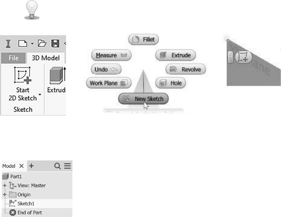
• Click the 3D Model tab > Sketch panel > Start 2D Sketch as shown in the following image on the left
or from the Sketch tab > Sketch panel > Start 2D Sketch. Then click a planar face, a work plane, or an
existing sketch in the browser.
• Press the S key (a keyboard shortcut) and click a planar face of a part, a work plane, or an existing
sketch in the browser.
• While not in the middle of an operation, right-click in the graphics window, and select New Sketch
from the marking menu as shown in the middle image. Then click a planar face, a work plane, or an
existing sketch in the browser.
• While not in the middle of an operation, click a planar face of a part, a work plane, or an exist-
ing sketch in the browser. Then right-click in the graphics window, and click 2D Sketch from the
mini-toolbar. The following image on the right shows the mini-toolbar after selecting an origin plane.
TIP: You can start the command rst, and then select a plane or you can select a plane rst
and then start the command.
Figure 2.15
After creating a sketch, a Sketch entry will appear in the browser as shown in the following image, and a Sketch
tab will appear in the ribbon. By default, after you have dened a sketch, the X and Y-axes will align automati-
cally to this plane, and you can begin to sketch.
Figure 2.16

44 Chapter 2 SKETCHING, CONSTRAINING, AND DIMENSIONING
SKETCHING THE 2D OUTLINE OF THE PART
As stated at the beginning of this chapter, 3D parts usually start with a 2D sketch of the outline shape of the
part. You can create a sketch with lines, arcs, circles, splines, or any combination of these elements. The next
section will cover sketching strategies, commands, and techniques.
Sketching Overview
When deciding what outline to start with, analyze how the nished shape will look. Look for the 2-dimensional
shape that best describes the part. When looking for this outline, try to look for a at 2-dimensional shape that
can be extruded or revolved to create a shape that other features can be added to, to create the nished part. It
is usually easier to sketch 2-dimensional geometry than 3-dimensional geometry. As you gain modeling expe-
rience, you can reect on how you created the model and think about other ways that you could have built it.
There is usually more than one way to generate a given part.
When sketching, draw the geometry so that it is close to the desired shape and size— you do not need to be
concerned about exact dimensional values. Even though Inventor allows islands in the sketch (closed objects
that lie within another closed object) it is NOT recommended to sketch islands (when you extrude a sketch,
island(s) may become voids in the solid). A better method is to place features, which make editing a part easier.
For example, instead of sketching a circle inside a rectangle to represent a hole, extrude a rectangle and then
place a hole feature.
The following guidelines will help you successfully generate sketches:
• Select a 2-dimensional outline that best represents the part. The 2D outline will be used to create the
base feature. A base feature is the rst feature. It is the feature other features will add material to or
remove material from.
• Draw the geometry close to the nished size. If you want a 20-inch square, for example, do not draw a
200-inch square. Use dynamic input to dene the size of the geometry. Dynamic input is covered in a
later section in this chapter.
• Create the sketch proportional in size to the nished shape. When drawing the rst object, verify its
size in the lower-right corner of the status bar. Use this information as a guide.
• Draw the sketch geometry so it doesn't lie over other geometry, that is, a line on top of another line.
• Do not allow the sketch to have a gap; the geometry should start and end at a single point, just as the
start and end points of a rectangle share the same point.
• Keep sketches simple. Leave out llets and chamfers when possible. Y
ou can easily place them as fea-
tures after making the sketch into a solid. The simpler the sketch, the fewer constraints and dimensions
are required to constrain the model.
SKETCH COMMANDS
Before you start sketching the outline of the part, examine the 2D sketching commands that are available. After
creating a sketch, the 2D sketch tab is current in the ribbon. The most frequently used commands will be ex-
plained throughout this chapter. Consult the help system for information about the remaining commands.
Figure 2.17
Using the Sketch Commands
After starting a new part, a sketch will automatically be active so that you can now use the sketch commands
to draw the shape of the part. To start sketching, issue the sketch command that you need, click a point in the
SKETCH COMMANDS 45
graphics window, and follow the prompt on the lower-left corner of the status bar. The sections that follow will
introduce techniques that you can use to create a sketch.
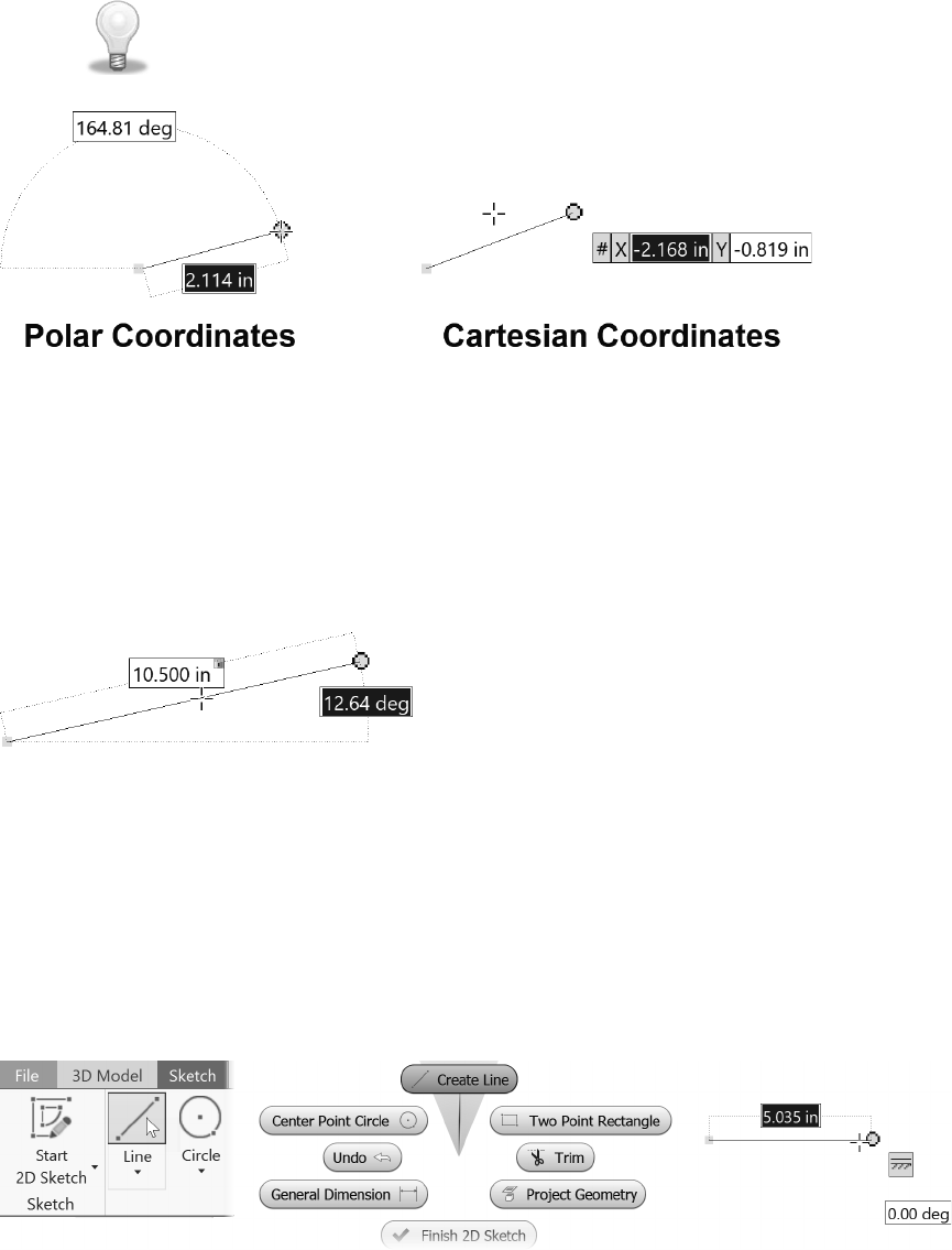
Dynamic Input in the sketch environment makes a Heads-Up Display (HUD), which shows information near the
cursor for many sketching commands that helps you keep your eyes on the screen. While using the Line, Circle,
Arc, Rectangle, or Point commands, you can enter values in the input elds. You can toggle between the value
input elds by pressing the
TAB key. The following image shows examples of entering Cartesian coordinates
and Polar coordinates.
TIP: If no data is entered in the input elds and you click in the graphics window to
locate geometry, dimensions will NOT automatically be placed. You can manually place
dimensions and constraints after the geometry is sketched.
Figure 2.18
Dimension Input
When dening lengths and angles for a second point, the dimensional values change as you move the cursor.
Press TAB to move to the next input eld or click in another cell. After entering a value and pressing the Tab
key, the value will be locked and a lock icon will appear to the right of the value as shown in the following
image. After a dimension’s value is locked, the parametric dimension will be created after clicking a point or
pressing the Enter key. You can change the value in an input eld by either clicking in the eld or pressing the
Tab key until the eld is highlighted and then typing in a new value.
Figure 2.19
Line Command
The Line command is one of the most powerful commands that you will use to sketch. Not only can you draw
lines with it, but you can also draw an arc from the endpoint of a line segment. To start sketching lines, click the
Line command from the Sketch tab > Create panel as shown in the following image on the left, or right-click
in a blank area in the graphics window and click Create Line from the marking menu as shown in the middle
image, or press the L key on the keyboard. After starting the Line command, you will be prompted to click a
rst point, select a point in the graphics window, and then click a second point. The image on the right shows
the line being created with the dynamic input as well as the horizontal constraint.
Figure 2.20

46 Chapter 2 SKETCHING, CONSTRAINING, AND DIMENSIONING
Drawing an Arc within the Line Command
You can continue drawing line segments, or you can sketch an arc from the endpoint. To make an arc from
the line command, move the cursor over the endpoint of a line segment or arc until a small gray circle appears
(Figure 2.21 left). Click the small circle and holding the left mouse button down, drag the cursor in the direction
to dene the arc.
Up to eight dierent arcs can be drawn, depending upon how you move the cursor. The arc will be tangent to
the horizontal or vertical edges that are displayed from the selected endpoint
.
Figure 2.21 right shows an arc that is tangent to the sketched line being drawn.
Figure 2.21
TIP: When sketching, look at the bottom-right of the status bar at the bottom of the
screen to see the coordinates, length, and angle of the objects you are drawing.
The following image shows the status bar when a line is being drawn.
Figure 2.22
Object Tracking – Inferred Points
If the Point Alignment On option is checked from the Sketch tab of the Application Options, dashed lines will
appear on the screen as you sketch. These dotted lines represent the endpoints; midpoints; and theoretical inter-
sections of lines, arcs, and center points of arcs and circles that represent their horizontal, vertical, or perpendic-
ular positions.
As the cursor gets close to these inferred points, it will snap to that location. If that is the point that you want,
click that point; otherwise, continue to move the cursor until it reaches the desired location. When you select in-
ferred points, no constraints (geometric rules such as horizontal, vertical, collinear, and so on) are applied from
them. Using inferred points helps create more accurate sketches. The following image shows the inferred points
from two midpoints that represent their horizontal and vertical position.
Figure 2.23

SKETCH COMMANDS 47
Automatic Constraints
As you sketch, a small constraint symbol appears representing geometric constraint(s) that will be applied to
the object. If you do not want a constraint to be applied, hold down the CTRL key when you click to create the
geometry.
Figure 2.24 shows a line being drawn from the arc, tangent to the arc, and parallel to the angled line, and the
dynamic input is also displayed. The symbol appears near the object from which the constraint is coming. Con-
straints will be covered in the next section.
Figure 2.24
Scrubbing
As you sketch, you may prefer to apply a constraint dierent from the one that automatically appears on the
screen. You may want a line to be perpendicular to a given line, for example, instead of being parallel to a dif-
ferent line. The technique to change the constraint is called scrubbing.
To place a dierent constraint while sketching, move the cursor so it touches (scrubs) the other object to which
the constraint should be related. Move the cursor back to its original location, and the constraint symbol changes
to reect the new constraint. The same constraint symbol will also appear near the scrubbed object, representing
that it is the object to which the constraint is matched. Continue sketching as normal.
The following image shows the top horizontal line being drawn with a parallel constraint that was scrubbed
from the bottom horizontal line. Without scrubbing the bottom horizontal line, the applied constraint would
have been perpendicular to the right vertical line.
Figure 2.25
Deleting Objects
To delete objects rst cancel the command that you are in by pressing the ESC key. Then select objects to delete,
and either press the DELETE key or right-click and choose Delete as shown in Figure 2.26.
Figure 2.26

48 Chapter 2 SKETCHING, CONSTRAINING, AND DIMENSIONING
Common Sketch Commands
The following table lists common 2D sketch commands. Some commands are available by clicking the down
arrow in the lower-right corner of the top command in the panel. Consult the help system for more information.
Command Function
Center-point Circle Creates a circle by clicking a center point for the circle and then a point on the
circumference of the circle.
Tangent Circle Creates a circle that will be tangent to three lines or edges by clicking the lines or
edges.
Three-Point Arc Creates an arc by clicking a start and endpoint and a point that will lie on the arc.
Tangent Arc Creates an arc that is tangent to an existing line or arc by clicking the endpoint of
a line or arc and then clicking a point for the other endpoint of the arc.
Center-Point Arc Creates an arc by clicking a center point for the arc and then clicking a start and
endpoint.
Two-Point Rectangle Creates a rectangle by dening a point and then clicking another point to dene
the opposite side of the rectangle. The edges of the rectangle will be horizontal
and vertical. If values were entered, dimensions will be placed on the rectangle.
Three-Point Rectangle Creates a rectangle by clicking two points that will dene an edge and then click-
ing a point to dene the third corner. You can also type values to dene the three
points of the rectangle, and dimensions will be created that dene the size of the
rectangle.
Two-Point Center
Rectangle
Creates a rectangle by dening a center point and another point to dene the
rectangle’s size or type values for the center point and its X and Y values of the
rectangle. The edges of the rectangle will be horizontal and vertical, and if values
were entered, dimensions will be created.
Three-Point Center
Rectangle
Creates a rectangle by dening a center point, a point to dene the rectangle’s
starting point and its angle and another point size or type values for the center
point, and size of the rectangle. The edges of the rectangle will be horizontal and
vertical, and if values were entered, dimensions will be created.
Center to Center Slot Creates a slot by dening the center-to-center distance, angle, and the diameter.
Overall Slot Creates a slot by dening the overall distance, angle, and then the diameter.
Center Point Slot Creates a slot by dening the center-to-center distance, angle, and the diameter.
Three Point Arc Slot
Creates an arc slot by dening a start point, end point, and an angle, a radius of
the center of the slot and then the diameter of the slot.
Center Point Arc Slot Creates an angled slot by dening a radius of the center of the slot and a starting
angle, an ending angle and then the diameter of the slot.
Fillet Creates a llet between two nonparallel lines, two arcs, or a line and an arc at a
specied radius. If you select two parallel lines, a llet is created between them
without specifying a radius. When the rst llet is created, a dimension will be
created. If many llets are placed in the same operation, you choose to either
apply or not apply an equal constraint.
Chamfer Creates a chamfer between lines. There are three options to create a chamfer:
both sides equal distances, two dened distances, or a distance and an angle.
Polygon Creates an inscribed or a circumscribed polygon with the number of faces that
you specify. The polygon’s shape is maintained as dimensions are added.
Mirror Mirrors the selected objects about a centerline. A symmetry constraint will be
applied to the mirrored objects.

SKETCH COMMANDS 49
Rectangular Pattern Creates a rectangular array of a sketch with rows and columns that you specify.
Circular Pattern Creates a circular array of a sketch with copies and spacing that you specify.
Oset Creates a duplicate of the selected objects that are a given distance away. By
default, an equal-distance constraint is applied to the oset objects.
Trim Trims the selected object to the next object it nds. Click near the end of the
object that you want trimmed. While using the Trim command, hold down the
SHIFT key to extend objects. If desired, hold down the CTRL key to select
boundary objects. While in the Trim command you can also hold down the left
mouse button and move the cursor to dynamically trim geometry. While in the
Dy
namic mode you can hold down the Shift key to dynamically extend geometry.
Extend Extends the selected object to the next object it nds. Click near the end of the
object that you want extended. While using the Extend command, hold down the
SHIFT key to trim objects. If desired, hold down the CTRL key to select bound-
ary objects. While in the Extend command, you can also click and hold down the
le
ft mouse button and move the cursor to dynamically extend geometry. While in
the Dynamic mode you can hold down the Shift key to dynamically trim geometry.
Selecting Objects
After sketching objects, you may need to move, rotate, or delete some or all the objects. To edit an object, it
must be part of a selection set. There are mulple methods that you can use to place objects into a selection set.
• CTRL or SHIFT Keys. You can select objects individually by clicking on them. To manually select
multiple individual objects, hold down the CTRL key or SHIFT key while clicking the objects. You
can remove selected objects from a selection set by holding down the CTRL or SHIFT key and rese-
lecting them.
As you select objects, their color will change to show that they have been selected.
• Window. You can select multiple objects by dening a selection window. Not all commands allow you
to use the selection window technique and only allow single selections. To dene the window
, click a
starting point. With the left mouse button depressed, move the cursor to dene the box. If you draw the
selection window from left to right (solid lines), as shown in the following image on the left, only the
objects that are fully enclosed in the window will be selected.
• Crossing window. If you draw the selection window from right to left (dashed lines), as shown in the
following image on the right, a crossing window is used and all the objects that are fully enclosed in
the selection window and the objects that are touched by the window will be selected.
• You can use a combination of the methods to create a selection set.
When you select an object, its color changes according to the color style that you are using. T
o remove all the
objects from the selection set, click in a blank section of the graphics windo
w.
Figure 2.27

50 Chapter 2 SKETCHING, CONSTRAINING, AND DIMENSIONING
In this exercise, you create a new part le and 2D Sketch geometry using basic construction techniques. In this
exercise, no dimensions will be created.
1 Click New from the Quick Access toolbar, click the English folder, and then double-click Standard
(in).ipt or if inch is the default unit; from the left side of the Quick Access toolbar you can click the
down arrow on the New icon and click Part.
2 Click Start 2D Sketch from the 3D Model tab > Sketch panel and then select the XY origin plane in the
graphics window as shown in the following image.
Figure 2.28
3 Start the Line command from the Sketch tab > Create panel.
4 C
lick on the origin point in the graphics window, move the cursor to the right about 4 inches, and when
the horizontal constraint symbol displays, click to specify a second point as shown in Figure 2.29.
You
may need to zoom back and pan the screen to see the entire line.
Figure 2.29
TIP: Symbols indicate the geometric constraints. In the image above, the symbol indicates that
the line is horizontal. When you create the rst entity in a sketch, make it close to nal size.
5 Move the cursor up until the perpendicular constraint symbol displays beside the rst line and then
click to create a perpendicular line that is approximately 2 inches as shown in
Figure 2.30
left.
6 Move the cursor to the left and create a horizontal line perpendicular to the vertical line that is approxi-
mately 1 inch. The perpendicular constraint symbol is shown in Figure 2.30 right.
Figure 2.30

EXERCISE 2-1: CREATING A SKETCH WITH LINES 51
7 Move the cursor downward to create a line perpendicular to the top horizontal line and about 1 inch.
8 Move the cursor left to create a line approximately 2 inches long and perpendicular to the inside
vertical line.
9 Move the cursor up and notice the perpendicular constraint symbol is displayed; to apply a parallel
constraint instead, move (scrub) the cursor over the inside vertical line to create a relationship to it.
Click when an inferred line (horizontal dotted line) appears from the top point as shown in Figure 2.31
left.
10 Move the cursor to the left until an inferred vertical line appears from the bottom-left point as shown in
Figure 2.31 right and then click to locate the point.
Figure 2.31
11 To close the prole right-click and choose Close from the menu.
12 Figure 2.32 left shows the sketch constraints and the image on the right without the constraints.
TIP: To see the sketch constraints select the geometry using window or
crossing window. Constraints will be covered in the next section in this chapter.
13 Right-click in the graphics screen, and choose Finish 2D Sketch.
Figure 2.32
14 Close the le. Do not save changes.
End of exercise.

52 Chapter 2 SKETCHING, CONSTRAINING, AND DIMENSIONING
In this exercise, you create a new part le, and then you create a prole consisting of lines and tangent arcs.
1 Click the New command, and then double-click Standard (in).ipt; or if inch is the default unit, from the
left side of the Quick Access toolbar you can click the down arrow of the New icon, and select Part.
2 Click the Start 2D Sketch command on the 3D Model tab > Sketch panel and then select the XY origin
plane.
3 Start the Line command by right-clicking in a blank area in the graphics window and click Create Line
from the marking menu.
4 Click on the projected origin point in the middle of the graphics window, and create a horizontal line to
the right of the origin point and type 3 (inches will be assumed as the unit because the part le is based
on the unit of inch) in the input eld. Press the tab key and move the cursor until the horizontal con-
straint symbol appears and then click. If the second point of the line lies o the screen, roll the mouse
wheel away from you to zoom out, hold down the mouse wheel, and drag to pan the view.
5 Create a perpendicular line, move the cursor up until the perpendicular constraint appears, type 1.5 in
the input eld as shown in the following image on the left, and then press enter.
6 In this step, you infer points, meaning that no sketch constraint is applied. Move the cursor to the
intersection of the midpoints of the right-vertical line and bottom horizontal line. Dotted lines (inferred
points) appear as shown in the image on the right, and then click to create the line. No dimension was
created since a value was not entered.
Figure 2.33
7 Next create a line parallel to the bottom line. If needed scrub the bottom line by moving the cursor
over the bottom line (do NOT click), and then move the cursor up and to the left until the vertical in-
ferred line and the constraints are displayed as shown in the following image on the left, and then click
to create the line.
8 Next sketch an arc while in the line command. With the Line command active move the cursor over
the left endpoint of the top horizontal line until the gray circle appears, click on the gray dot at the left
end of the line, holding down the left mouse button drag the cursor to the left and then down to pre-
view a tangent arc. Do not release the mouse button.
9 Move the cursor over the left endpoint of the rst line segment until a coincident constraint (green
circle) and the two tangent constraints at start and end points of the arc are displayed as shown in the
following image on the right.

CONSTRAINING A SKETCH 53
Figure 2.34
10 Release the mouse button to create the arc.
11 Right-click in the graphics window, and choose OK from the marking menu. Later in this chapter you
will learn how to create dimensions.
12 Click Finish Sketch from the Sketch tab > Exit panel.
13 Close the le. Do not save changes.
End of exercise.
CONSTRAINING A SKETCH
After you draw a sketch, you may want to add geometric constraints to it to add design intent. Geometric con-
straints apply behavior to a specic object or create a relationship between two objects. An example of using
a constraint is applying a vertical constraint to a line so that it will always be vertical. You can apply a parallel
constraint between two lines to make them parallel to one another; then as you change the angle of one of the
lines, the angle of the other line will change with it.
You can apply a tangent constraint to a line and an arc or to
two arcs.
When you add a constraint, the number of constraints or dimensions that are required to fully constrain the
sketch will decrease. On the bottom-right corner of Autodesk Inventor, the number of constraints or dimensions
will be displayed like what is shown in the following image. A fully constrained sketch is a sketch whose ob-
jects cannot move or stretch.
Figure 2.35
Constrain to the Origin Point
When sketching, it is recommended to constrain a point on the sketch to the origin point with a coincident con-
straint or dimension a point on the sketch to the origin point so it cannot move. You could apply a x constraint
instead of using the origin point, but it is not recommended. When a sketch is constrained to the origin point,
Inventor will change the color of constrained objects. If the sketch is not constrained to the origin point, objects
are free to move in the sketch and the color of the objects will not change.
TIP: Autodesk Inventor does not force you to fully constrain a sketch. However, it is
recommended that you fully constrain a sketch, as this will allow you to better predict
how future changes will aect the sketch and part.

54 Chapter 2 SKETCHING, CONSTRAINING, AND DIMENSIONING
Constraint Types
Autodesk Inventor has 12 geometric constraints that you can apply to sketch geometry. The following image
shows the constraint types that can be applied from the Sketch tab > Constrain panel.
Figure 2.36
The following chart describes the geometric constraints.
Icon Constraint Function
Coincident A point is constrained to lie on another point or curve (line, arc, etc.).
Collinear Two selected lines will line up along a single line; if the rst line moves,
so will the second. The two lines do not have to be touching.
Concentric Arcs and/or circles will share the same center point.
Fix Applying a x constraint to a point prevents the constrained point from
moving. Multiple points in a sketch can be xed. If you select a line seg-
ment, the angle of the line will be xed and only its length can change.
Parallel Two selected lines will remain parallel to one another.
Perpendic-
ular
Lines will remain at 90° angles to one another.
Horizontal Line is positioned parallel to the X-axis, or a horizontal constraint can be
applied between any two points in the sketch. The selected points will be
aligned such that a line drawn between them will be parallel to the X-axis.
Tip: Your keyboard's dash "-" key is a quick shortcut to start the Horizontal
Constraint command.
Vertical Line is positioned parallel to the Y-axis, or a vertical constraint can be
applied between any two points in the sketch. The selected points will be
aligned such that a line drawn between them will be parallel to the Y-axis.
Tangent An arc, circle, or line will remain tangent to another arc or circle.
Smooth (G2) A spline and another spline, line, or arc that connect at an endpoint with a
coincident constraint will represent a smooth G2 (continuous curvature)
condition.
Symmetry Selected points dening the geometry are made symmetric about a
selected line.
Equal If two arcs or circles are selected, they will have the same radius or diam-
eter. If two lines are selected, they will become the same length. If one of
the objects changes, so will the constrained object. If the Equal constraint
is applied after one of the arcs, circles, or lines has been dimensioned, the
second arc, circle, or line will take on the size of the rst one. If you select
multiple similar objects (lines, arcs, etc.) before selecting the command,
the constraint is applied to all of them.

CONSTRAINING A SKETCH 55
Adding Constraints
As stated previously, you can apply constraints while you sketch objects. You can also apply additional con-
straints after the sketch is drawn. However, Inventor will not allow you to over-constrain the sketch or add
duplicate constraints. If you add a constraint that conicts with another, you will be warned with the message,
“Adding this constraint will over-constrain the sketch.” For example, if you try to add a vertical constraint to a
line that already has a horizontal constraint, you will be alerted.
To add a constraint, follow these steps:
1 Click a constraint from the Constrain panel, or right-click in the graphics window and choose Create
Constraint from the menu and select specic constraint from the menu (see iFigure 2.36.)
2 Click the object or objects then apply the constraint.
Showing Constraints
To display the geometric constraints that are applied to a sketch, do one of the following:
• Select the geometry in the graphics window by selecting individual objects or using a window or
crossing selection (see "Selecting Objects" on page 49 if needed.)
• Click the Show Constraints command from the Status Bar as shown in Figure 2.37 left or from the
Constrain panel as shown in the middle image.
• Right-click in a blank area in the graphics window and click Show All Constraints from the menu.
• Press the F8 key.
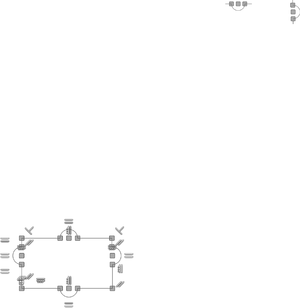
The constraints on the selected geometry will be displayed. The yellow squares represent coincident constraints;
move the cursor over a yellow square to display the two coincident constraints for the point. The image on the
right shows all the constraints in a sketch.
Figure 2.37
Modifying Constraint Size
You can set the Annotation Scale to modify the size of the constraint icons displayed on the screen. Use the
Tools tab > Options panel > Application Options, and near the middle right of the General tab modify the Anno-
tation Scale factor.
Figure 2.38 shows the Annotation Scale increased from 1.0 to 1.5. This setting also changes the size of the
dimensions in a sketch. This change has no eect on the size of dimensions in a drawing.
Figure 2.38

56 Chapter 2 SKETCHING, CONSTRAINING, AND DIMENSIONING
Deleting Constraints
To delete the constraint(s), select a constraint or multiple constraints using one of the selection methods. Right-
click and click Delete from the menu as shown in the following image on the left.
As an alternate method to deleting a constraint, you can press the Delete key once the constraint is selected.
• To delete all constraints except the coincident constraints, select or use the window or crossing
selection technique, right-click and click Delete Constraints from the menu as shown in the image
on the right.
Figure 2.39
Hiding Constraints
You can hide the display symbol for individual or all geometric constraints. To perform this task, do one of the
following:
To hide a constraint:
• Move the cursor over a constraint, right-click and click Hide from the marking menu as shown in
the following image on the left.
To hide all constraints, do one of the following:
• Move the cursor over a constraint, right-click and click Hide All Constraints from the marking
menu as shown in the image on the left.
• Click Hide All Constraints on the Status Bar as shown in the middle image. This is the same icon you
selected to Show All Constraints.
• Right-click in a blank area in the graphics window and click Hide All Constraints on the menu as
shown in the following image on the right.
• Press the F9 key.
Figure 2.40

CONSTRAINING A SKETCH 57
Construction Geometry
Construction geometry can help you create sketches that would otherwise be dicult to constrain. You can
constrain and dimension construction geometry like normal geometry, but construction geometry will not be
recognized as a prole edge in the part when you turn the sketch into a feature. Normal sketch geometry by
default is visible in features created from the sketch.
Construction geometry can reduce the number of constraints and dimensions required to fully constrain a
sketch, and can help dene the sketch. For example, a construction circle that is tangent to the inside of a
hexagon (drawn with individual lines and not the Polygon command) can drive the size of the hexagon. Without
construction geometry
, the hexagon would require six constraints and dimensions. With construction geometry,
it would require only three constraints and dimensions; the circle would have tangent or coincident constraints
applied to it and the hexagon.
To create construction geometry change the line style before or after you sketch the geometry using one of the
following ways:
• After creating the sketch, select the geometry that you want to change and click the Construction
icon on the Format panel as shown in Figure 2.41.
• Before sketching, click the Construction icon on the Format panel. All geometry created will be
construction until the Construction command is deselected. Remember to click the Construction
icon to turn it o afterward to avoid all you draw being construction geometry.
Figure 2.41
After turning the sketch into a feature, the construction geometry will be consumed with the sketch and is main-
tained in the sketch. When you edit a feature’s sketch that has construction geometry, the construction geometry
will reappear during editing and disappear when the part is updated.
You can add or delete construction geometry in a sketch just like normal sketch geometry can be. In the graph-
ics window, construction geometry displays as a dashed line, lighter colored and thinner than normal geometry.
Figure 2.42 left shows a sketch with an angled construction line. The angled line has a coincident constraint
applied to every endpoint that it touches. The image at right shows the sketch after it has been extruded. Notice
that the construction line was not extruded.
Figure 2.42

58 Chapter 2 SKETCHING, CONSTRAINING, AND DIMENSIONING
Number of Required Constraints or Dimensions
While constraining and dimensioning a sketch, there are multiple ways to determine the number of constraints
or dimensions that are required to fully constrain the sketch. When you add a constraint or dimension, the num-
ber of constraints or dimensions needed to constrain the sketch decreases. A fully constrained sketch is a sketch
whose geometry cannot move or stretch.
The bottom-right of the status bar shows the number of constraints or dimensions needed to fully constrain the
sketch (Figure 2.43 left.) When no additional constraints or dimensions are needed to dene the sketch, the
message Fully Constrained appears at the bottom-right of the status bar (middle image), and in the browser, a
pushpin icon appears to the left of the Sketch entry (right.)
Figure 2.43
Degrees of Freedom
To see the areas in the sketch that are NOT constrained, you can display the degrees of freedom. While a sketch
is active, click Show Degree of Freedom on the status bar, as shown in Figure 2.44 left, or right-click in a blank
area of the graphics window and choose Show All Degrees of Freedom from the menu.
Lines and arcs with arrows will appear on your sketch as shown in the middle image. As you add constraints
and dimensions to the sketch, degrees of freedom will disappear.
To remove the degree of freedom symbols from the screen, use the status bar to click Hide All Degrees of Free-
dom, as shown in Figure 2.44 right, or right-click in a blank area in the graphics window and choose Hide All
Degrees of Freedom from the menu.
Figure 2.44
Dragging a Sketch
Another method to determine if an object is constrained is to try to drag it to a new location. While not in a
command, click a point or an edge, or select multiple objects on the sketch. With the left mouse button de-
pressed, drag it to a new location. If the geometry stretches, it is under constrained.
For example, if you draw a rectangle that has two horizontal and two vertical constraints applied to it and you
drag a point on one of the corners, the size of the rectangle will change, but the lines will maintain their horizon-
tal and vertical behaviors. If dimensions are set on the object, they will prevent the object from stretching.

EXERCISE 2-3: ADDING AND DISPLAYING CONSTRAINTS 59
In this exercise, you add geometric constraints to sketch geometry to control the shape of the sketch.
1 Click the New command, click the English folder, and double-click Standard (in).ipt.
2
Click the Start 2D Sketch command on the 3D Model tab > Sketch panel and then select the XY origin plane.
3 Sketch the geometry as shown in the following image, with an approximate size of 2 inches in the X
(horizontal) direction and 1 inch in the Y (vertical) direction. Do not apply dimensions dynamically.
Place the lower-left corner of the sketch on the origin point. Right-click in the graphics window, and
then click OK. By starting the line at the origin point, that point is constrained to the origin with a
coincident constraint.
4 Click Show All Constraints on the Status Bar, or press the F8 key. Your screen should resemble the
following image.
Figure 2.45
5 If another constraint appears, place the cursor over it, right-click, and then click Delete from the mark-
ing menu.
6 On the Constrain panel, click the Parallel constraint icon.
7 Select the two angled lines. Depending upon the order in which you sketched the lines, the angles may
be opposite of the following image on the left. The constraints that are applied are previewed.
8 Press the ESC key twice to stop adding constraints.
9 The new constraints you just added are not displayed. Press the F8 key to refresh the visible con-
straints. Your screen should resemble the following image.
Figure 2.46
10 Select the top horizontal line in the sketch and drag the line. Notice how the sketch changes its size,
but not its general shape. Try to drag the bottom horizontal line. The line cannot be dragged as it is
constrained.
11 Select the endpoint on the bottom-right horizontal line, and drag the endpoint. The lines remain par-
allel due to the parallel constraints. Notice on the bottom-right of the Status Bar that 3 dimensions are
needed to fully constrain the sketch.
12 On the Sketch tab > Constrain panel, click the Perpendicular constraint icon.

60 Chapter 2 SKETCHING, CONSTRAINING, AND DIMENSIONING
13 Select the bottom horizontal line and the angled line on the right side.
14 Even though it may appear that the rectangle is fully constrained, the height and length of the rectangle
still need to be dened with dimensions. Notice on the bottom-right that the Status Bar is down to 2
dimensions to fully constrain the sketch.
15 Place the cursor over the icon for the parallel constraint on the right-vertical line, right-click, and click
Delete from the marking menu as shown in the following image on the left. The parallel constraint that
was applied to both angled lines is deleted and 3 dimensions would be needed to fully constrain the
sketch.
Figure 2.47
16 Click and drag the top-left corner of the rectangle to the left as shown in the following image. Notice
that the line on the right does not move because it’s perpendicular to the bottom horizontal line.
Figure 2.48
17 Click Hide All Constraints on the Status Bar, or press the F9 key.
18 Use a window (drawn left to right) to select the 4 lines and then right-click and choose Delete from the
marking menu.
19 Use the Line command to sketch the geometry as shown in the following image with an approximate
size of 3 inches in the X direction and 1.5 inches in the Y direction. Place the lower-left point of the
sketch on the origin (projected center point). Do not apply dimensions dynamically. Right-click in the
graphics window, and then click OK.
Figure 2.49
20 Inspect the constraints by dragging dierent points and edges.
EXERCISE 2-3: ADDING AND DISPLAYING CONSTRAINTS 61
21 Next make the arcs equal in size. From the Constrain panel, click the Equal constraint command or
press the
= key on the keyboard.
22 Select the arc on the left and then the bottom arc.
23 Select the arc on the left and then the arc on the right side.
24 Select the arc on the left and then the arc on the top.
25
Next align the line segments if necessary. From the Constrain panel, click the Collinear constraint command.
Note: if the endpoints and center point of the arcs are aligned horizontally or vertically
when they were sketched, you will receive a message “Adding this constraint will over-constrain
the sketch.” If you see this message click Cancel in the dialog box for steps 22 a. b. c. and d.
a. Select the two bottom-horizontal lines.
b. Select the two top-horizontal lines.
c. Select the two left-vertical lines.
d. Select the two right-vertical lines.
26 To stop applying the collinear constraint, either right-click and click Cancel (ESC) from the marking
menu or press the ESC key.
27 Next you will align the top and bottom arcs vertically. On the Constrain panel, click the Vertical con-
straint command.
28 Select the center point of the bottom arc and then click the center point of the top arc.
29 Next you will align the left and right arcs horizontally. On the Constrain panel, click the Horizontal
constraint command.
30 Click the center point of the left arc, and then click the center point of the right arc.
31 To stop applying the constraints, right-click and click Cancel (ESC) from the marking menu, or press
the ESC key.
32 If desired, you can move the arcs by clicking and dragging on them.
33 Display all the constraints by pressing the F8 key. Your screen should resemble the following image.
Figure 2.50
34 Hide all the constraints by pressing the F9 key.
35 Click on an endpoint in the sketch and drag the endpoint. Try dragging dierent points, and notice how
the sketch changes.

62 Chapter 2 SKETCHING, CONSTRAINING, AND DIMENSIONING
36 Next delete geometry. as directed:
a. Press the ESC key twice to cancel any command.
b. Click a point above and to the left of the top arc and drag a window down and to the right so it
encompasses the arc on the right as shown in the following image on the left.
c. Release the mouse button and press the Delete key on the keyboard.
37 Close the open line segments. Drag the open endpoints onto each other until your sketch resembles the
following image on the right. A green circle will appear when the two endpoints are near each other;
this applies a coincident constraint.
38 Note, you could have connected the two open endpoints by using the coincident constraint.
Figure 2.51
39 Next center the arcs in the middle of the sketch. On the Constrain panel, click the Vertical constraint
command, click the center point on the bottom arc and then the midpoint of the top horizontal line as
shown in the following image on the left.
On the Constrain panel, click the Horizontal constraint command, click the center point on the left arc
and the midpoint of the right vertical line as shown in the following image on the right.
Figure 2.52
40 Click on dierent points and drag them, notice how the sketch changes shape, but the arcs are always
centered as shown in the following image.
Figure 2.53
41 Close the le. Do not save changes.
Note: Dimensions are needed to fully constrain the sketch. Dimensions are covered in the next section.
End of exercise.
ADDING DIMENSIONS MANUALLY 63
The last step to constraining a sketch is to add dimensions that were not added dynamically. The dimensions
you place will control the size of the sketch and can also appear in the part drawing views when they are gen-
erated. When placing dimensions, try to avoid having extension lines go through the sketch, as this will require
more cleanup when drawing views are generated. Click near the side from which you anticipate the dimensions
will originate in the drawing views.
All dimensions that you create are parametric as well as the dynamic dimensions that are placed automatically
when sketching geometry. Parametric means that they will change the size of the geometry.
Scale Sketch
If the sketch is not constrained to the origin point and no dimension was dynamically added to the sketch when
it was created, then the entire sketch will be uniformly scaled when the rst dimension is added.
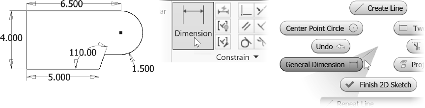
General Dimensioning
The General Dimension command can create linear, angle, radial, or diameter dimensions one at a time. The fol-
lowing image on the left shows an example of a dimensioned sketch. To start the General Dimension command,
follow one of these techniques:
• Click the General Dimension command from the Sketch tab > Constrain panel as shown in the
following image in the middle.
• Right-click in the graphics window and click General Dimension from the marking menu as shown
in the image on the right.
• Press the shortcut key D.
Figure 2.54
When you place a linear dimension, the extension line of the dimension will snap automatically to the nearest
endpoint of a selected line; when an arc or circle is selected, it will snap to its center point. To dimension to a
tangent point of an arc or circle, see “Dimensioning to a Tangent of an Arc or Circle” later in this chapter.
After you select the General Dimension command, follow these steps to place a dimension:
1. Select the geometry to be dimensioned.
2. After selecting the geometry, a preview image will appear attached to your cursor showing the
type of dimension. If the dimension type is not what you want, right-click, and then select the cor-
rect style from the menu. After changing the dimension type, the dimension preview will change
to reect the new style.
3. Click to place the dimension.
4. Enter a value for the dimension.
The next sections cover how to dimension specic objects and how to create specic types of dimensioning
with the Dimension command.
64 Chapter 2 SKETCHING, CONSTRAINING, AND DIMENSIONING
Dimensioning Lines
There are multiple techniques for dimensioning a line. Use the Dimension command and do one of the following:
• Click near two endpoints, move the cursor until the dimension is in the correct location, and click.
• To dimension the length of a line, click anywhere on the line; the two endpoints will be selected auto-
matically. Move the cursor until the dimension is in the correct location and click.
• To dimension between two parallel lines, click one line and then the next, and then click a point to
locate the dimension.
•
To create a dimension whose extension lines are perpendicular to the line being dimensioned, click the
line and then right-click. Click Aligned from the menu, and then click a point to place the dimension.
Dimensioning Angles
To create an angular dimension, use the General Dimension command, click two lines whose angle you want to
dene, move the cursor until the dimension is in the correct location. Place the dimension by clicking on a point.
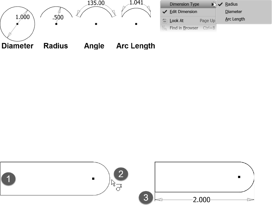
Dimensioning Arcs and Circles
To dimension an arc or circle: start the General Dimension command, click on the circle’s circumference, move
the cursor until the dimension is in the correct location, and click. By default, when you dimension a circle, the
default is a diameter dimension; when you dimension an arc, the result is a radius dimension. To change a radial
dimension to diameter or a diameter to radial, right-click before you place the dimension and select the style
from the Dimension
Type menu.
To dimension the angle of the arc: start the Dimension command, click the arc’s circumference, click the arc’s
center point, and then place the dimension. You can also click the arc's center point and then its circumference.
You can also add an arc length dimension this way. Start the dimension command, then click on the arc, right-
click and choose Arc Length from the Dimension Type menu, then click a point to locate the dimension.
Figure 2.55
Dimensioning to a Tangent of an Arc or Circle
To dimension to a tangent of an arc or circle, follow these steps:
1. Start the General Dimension command.
2. Select a line that is parallel to the tangent arc or circle that will be dimensioned, labeled (1) in the
following image on the left.
3. Move the cursor over the arc or circle until the tangent constraint symbol appears, labeled (2) in
the following image on the left.
4. Then move the cursor until the dimension is in the correct location and click to create the dimen-
sion, labeled (3) in the following image on the right.
Figure 2.56

ADDING DIMENSIONS MANUALLY 65
To dimension to two tangents, follow these steps:
1. Start the General Dimension command.
2. Select an arc or circle that includes one of the tangents to which it will be dimensioned. The fol-
lowing image illustrates an example of dimensioning a slot; the rst selection is labeled (1).
3. Move the cursor over a second arc or circle until the tangent constraint symbol appears, as shown
in the following image on the left, labeled (2).
4. Click to select the tangent point and then move the cursor until the dimension is in the correct
location. Then click to create the dimension, labeled (3) in the following image on the right.
Figure 2.57
Entering and Editing a Dimension Value
After placing the dimension, you can change its value. Depending on your settings, the Edit Dimension dialog
box may or may not appear automatically after you place the dimension. The Edit Dimension options can be set
by any one of the following:
• Click the Tools tab > Options panel > Application Options. On the Sketch tab of the Application
Options dialog box, from the Constrain Settings area, click the Settings button and then click the
box next to "Edit dimension when created" as shown in Figure 2.58 left.
• Set the option by right-clicking in the graphics window while placing a dimension and click Edit
Dimension from the menu as shown in Figure 2.58 right. This method will change the application
option "Edit Dimension when created" as previously described.
If "Edit dimension when created" is checked, the Edit Dimension dialog box appears automatically after you
place the dimension. Otherwise, the dimension will be placed with the default value.
Figure 2.58
To edit a dimension that has already been created, double-click on the dimension, and the Edit Dimension dia-
log box will appear, as shown in Figure 2.59.
Enter the new value and unit for the dimension; then either press ENTER or click the checkmark in the Edit
Dimension dialog box. If no unit is entered, the units that the le was created with will be used. Enter the exact
value — do not round up or down. The accuracy of the dimension that is displayed in a sketch is set in the
Document Setting. For example, if you want to enter 4 1/16 as a decimal, enter 4.0625 in not 4.06 in. You can
set how many decimal places to display on the drawing later, but create your model with as much accuracy as
possible.
Figure 2.59

66 Chapter 2 SKETCHING, CONSTRAINING, AND DIMENSIONING
Fractions
Inventor allows you to enter a fraction when such a value is required. With the Length unit in the Tools tab >
Options panel > Document Settings > Units tab set to any non-metric unit, as shown in Figure 2.60 left, when
a fraction is entered, it will display as such in the graphics window and in the Edit Dimension dialog box. If
the Length unit is set to a metric unit and a fraction is entered, the decimal equivalent will be displayed in the
graphics window but the fraction will be shown in the Edit Dimension dialog box.
After entering a fraction, you can click on the right-faced arrow and set the type of dimension to display:
Decimal, Fractional, or Architectural as shown in the middle of the following image.
When entering fractions do not use a dash to separate the fraction, just add a space. For example, enter 4 1/16,
not 4-1/16, because Inventor interprets the — as part of an equation and would return the value 3.9375. Figure
2.60 right shows the fraction displayed in the graphics window.
Figure 2.60
TIP: When placing dimensions, it is recommended that you place the smallest dimensions
rst. This will help prevent the geometry from ipping in the opposite direction.
Repositioning a Dimension
Once you place a dimension, you can reposition it, but the origin points cannot be moved. Follow these steps to
reposition a dimension:
1. Exit the current operation either by pressing ESC twice or right-clicking and then clicking Cancel
(ESC) from the marking menu.
2. Move the cursor over the dimension until the move symbol appears as shown in Figure 2.61.
3.
With the left mouse button depressed, move the dimension to a new location and release the button.
Figure 2.61
Fully Constrained Sketch
As described in the “Constraining the Sketch” section, as you add constraints and dimensions to a sketch, the
number of required dimensions decreases. When no more constraints or dimensions are needed to constrain the
sketch, instead of a number in “dimensions needed” on the bottom-right of the status bar Fully Constrained will
show as in Figure 2.62 left. The icon to the left of the Sketch entry in the browser displays a push-pin when the
sketch is fully constrained as shown in Figure 2.62 right.

ADDING DIMENSIONS MANUALLY 67
Figure 2.62
Over Constrained Sketch
As explained in the “Adding Constraints” section, Inventor does not allow over-constrained sketches or dupli-
cate constraints. The same is true when adding dimensions. If you add a dimension that conicts with another
constraint or dimension, you will be warned that this dimension will over-constrain the sketch or that it already
exists. You can either cancel the operation and no dimension will be placed, or accept the warning and a driven
dimension will be created.
A driven dimension is a reference dimension. It is not a parametric dimension—it reects the size of the points
to which it is dimensioned. If the part changes, the driven dimension updates to show the new value. A driven
dimension will appear with parentheses around the dimension’
s value—for example, (2.500). When you place a
dimension that will over-constrain a sketch, a dialog box will appear like the following image.
Figure 2.63
Relax Mode
When you try to place a constraint or add a dimension and receive the over-constrained message, if you want
the constraint or dimension to take precedence, you can turn on relax mode. With relax mode on, when you
reapply the constraint or add the dimension, the conicting constraint will automatically be deleted, except for
Coincident, Smooth,
Tangent, Symmetry, Pattern, and Project constraints. A conicting dimension will become
a driven dimension. While in relax mode, if you are unable to add the new constraint or dimension, you may
need to manually delete one of the Coincident, Smooth, Tangent, Symmetry, Pattern, and Project constraints.
Turn on relax mode by clicking the Relax Mode icon on the Status Bar as shown in Figure 2.64 left. You can
also click Constrain Settings from the Sketch tab > Constrain panel, then use the Relax Mode tab to check
Enable Relax Mode as shown in Figure 2.64 middle. When you apply a constraint or dimension that would
over-constrain a sketch, a dialog box appears stating a constraint or dimension will be deleted to solve the con-
ict as shown in Figure 2.64 right.
Another method to remove conicting constraints or dimensions is to drag a point or edge while in Relax Mode
and conicting constraints or dimensions will be deleted.
TIP: When done constraining a sketch, turn o Relax Mode to return to normal editing. If you
don't turn it o, sketch points and objects can be changed by accidentally dragging them.

68 Chapter 2 SKETCHING, CONSTRAINING, AND DIMENSIONING
Figure 2.64
Figure 2.65 left shows a fully constrained rectangle with geometric constraints visible. With Relax Mode on
a 120-degree angle dimension was placed. Clicking Yes in the warning dialog box caused the dimension to
be created, and the perpendicular constraint in the lower-right corner deleted as shown in the middle image.
The image at right shows the sketch after a perpendicular constraint was applied to the bottom-horizontal and
left-vertical lines. Notice the 120-degree dimension was maintained.
Figure 2.65
Driven Dimension
Driven dimensions can also be created using the Driven Dimension option. A driven dimension does NOT re-
duce the dimensions needed to constrain the sketch; it only reports the length of the object. You use this option
to show reference dimensions.
Select Driven Dimension from the Sketch tab > Format panel, as shown in Figure 2.66
left. With the Driven
Dimension icon highlighted, use the Dimension command as usual to create a driven dimension. (Don't forget
to turn it o when you are nished.) Driven dimensions are represented in the sketch with parentheses around
the value; parametric dimensions do not use parentheses. Without the Driven Dimension option active, regular
parametric dimensions are created, which is the default.
The Driven Dimension option can also be used to change an existing dimension to either a driven or back to
normal by selecting it and clicking Driven Dimension. Figure 2.66 right shows an example of a 5.250 driven di-
mension referencing the overall length of the sketch. The three parametric dimensions control the length of the
sketch. If a parametric dimension value changes, the driven dimension updates to reect the change in overall
length.
Figure 2.66
TIP: Avoid over using driven dimensions as they do not parametrically control the
size of the sketch. They are only used for reference.

EXERCISE 2-4: CONSTRAINING AND DIMENSIONING A SKETCH 69
In this exercise, you add dimensional constraints to a sketch. Note: this exercise assumes that the “Edit di-
mension when created” and “Autoproject part origin on sketch create” options are checked in the Application
Options dialog box under the Sketch tab. Experiment with Autodesk Inventor’s color schemes to see how the
sketch objects change color when they are constrained.
1 Click New, choose the English folder. Double-click Standard (in).ipt to select it.
2 Click Start 2D Sketch from the 3D Model tab > Sketch panel. Select the XY origin sketch plane.
3 Use the Line command from the Sketch tab > Create panel. Draw a line starting from the origin point,
then move the cursor to the right, type 5 in the distance input. Press Tab and click a point when the
horizontal constraint shows below the degrees input eld as shown in Figure 2.67 left.
4 Next place an angled line and a dynamic dimension to dene the angle. Press Tab and type 150 for the
angle input, press the Tab key, and then click a point to the upper right as shown in Figure 2.67 right.
The distance should be about 2 inches but the dimension is not needed to de ne this sketch.
Figure 2.67
5
Sketch the geometry shown in the following image. When sketching, ensure that a perpendicular con-
straint is not applied between the two angled lines. If needed, hold down CTRL while sketching the top
angled line to prevent the sketch constraint being applied. Make the arc tangent to both adjacent lines.
Figure 2.68
6 Horizontal Constraint command from the Sketch tab > Constrain panel to add a horizontal constraint
between the midpoint of the left vertical line and the center of the arc as shown in Figure 2.69 left.
7 Use Vertical Constraint from the Sketch tab > Constrain panel and add a vertical constraint between
the endpoints of the angled lines nearest to the right side of the sketch as shown in Figure 2.69 right.
Figure 2.69

70 Chapter 2 SKETCHING, CONSTRAINING, AND DIMENSIONING
8 Press the
=
key and select the two angled lines to add an equal constraint to them.
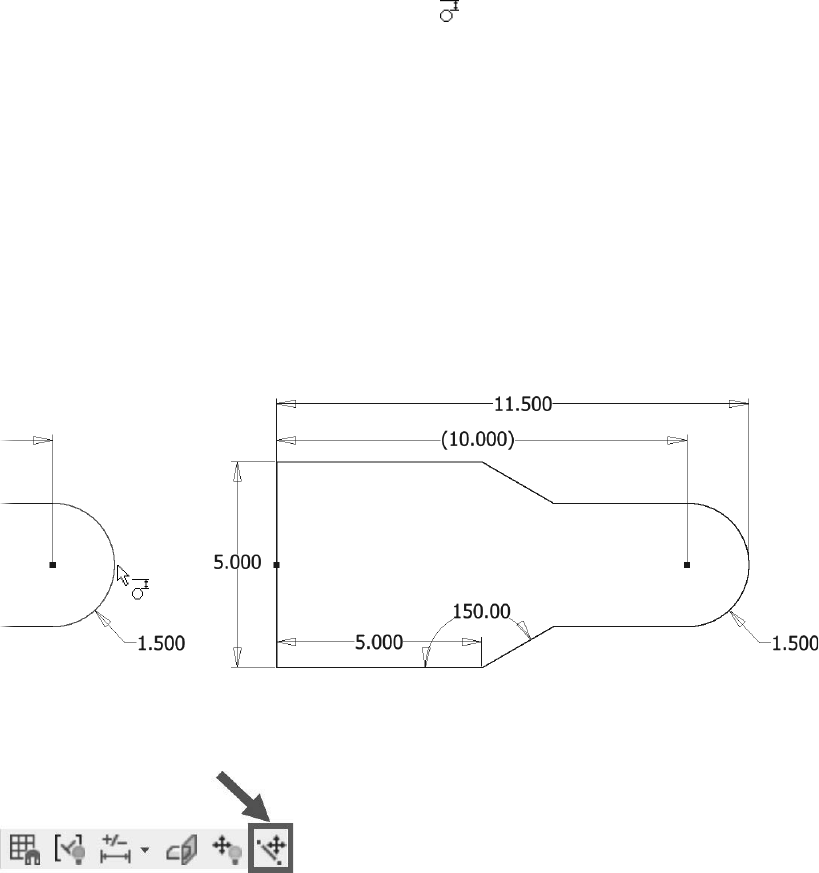
9 Click General Dimension from the Sketch tab > Constrain panel and add a radial dimension to the arc.
Move the cursor to position the dimension near the lower right corner of the sketch, then click a point
and enter the value 1.5. If the Edit Dimension dialog doesn't appear, double-click the dimension and
change it to 1.5. Click the checkmark to nish.
TIP: To show the Edit Dimension dialog box during dimension placement, right-click in the
graphics window and click Edit Dimension from the menu.
10 While still in the General Dimension command, add a vertical dimension to the vertical line, click a
point to locate the dimension to its left, enter 5, and click the checkmark. When complete, your sketch
should resemble the following image. Notice on the Status Bar bottom right, 1 dimension is required to
fully constrain the sketch.
Figure 2.70
11 Add a horizontal dimension by selecting the left vertical line and the center point of the arc (or on top
of the arc). Locate the dimension above the sketch. Enter 10 for the value as shown in Figure 2.71.
Figure 2.71
12 Press ESC twice to end the command. The Status Bar dimensions required section should display “Ful-
ly Constrained.” In the browser, the icon to the left of the sketch should show a pushpin.
13 Try clicking and dragging dierent points of the sketch. The points do not change as it is fully con-
strained and dimensioned.
14 Click the Relax Mode icon in the Status Bar to turn it on as shown in Figure 2.72.
Figure 2.72
EXERCISE 2-4: CONSTRAINING AND DIMENSIONING A SKETCH 71
15 Click and drag dierent points on the sketch. The dimensions will change to reect their new value.
16 Use Undo from the Quick Access toolbar to return the sketch to the values shown in Figure 2.71.
17 While still in Relax Mode, use General Dimension to add an overall horizontal dimension by clicking
the vertical line (not an endpoint) and moving the cursor near the right tangent point of the arc until the
glyph of a dimension with a circle appears , as shown in Figure 2.73 left.
• Locate the dimension above the 10.000 dimension.
• Click Yes to allow the highlighted dimension to be changed to a driven dimension.
• Accept the default length of 11.500 by clicking the green check mark in the Edit Dimension dialog.
• Notice that a perpendicular constraint was removed,
18 Select the 10.000 dimension and toggle it to a driven dimension by clicking Driven Dimension from
the Sketch Tab > Format panel.
19 Add a perpendicular constraint between the left vertical line and the top horizontal line. Your sketch
should resemble Figure 2.73 right.
Note that another option is to change the 10.000 dimension to a driven dimension and then add the
11.500 dimension.
Figure 2.73
20 Click Relax Mode from the Status Bar to turn it o as shown in Figure 2.74.
Figure 2.74
21 Edit some sketch dimensions by double-clicking on the dimension’s value and typing in a new one.
Press ENTER on the keyboard or click the green check mark in the Edit Dimension dialog box when
done. Examine how the sketch changes. The arc should remain in the middle of the vertical line. No-
tice how the driven dimension changes when the horizontal, angle or radial dimension values change.

72 Chapter 2 SKETCHING, CONSTRAINING, AND DIMENSIONING
22 Delete the horizontal constraint between the center of the arc and the midpoint of the vertical line by
selecting the center point of the arc, select the horizontal constraint above the center point, right-click
and click Delete from the menu as shown in the following image.
Figure 2.75
23 Prove the arc can move by clicking and dragging on the center point of the arc.
24 Display the visibility of all the constraints by using window to select all of the geometry.
25 Click in an empty area of the graphics window so the constraints disappear.
26 From the Status Bar, click Show All Constraints, as shown in Figure 2.76.
Figure 2.76
27 Practice deleting and adding other constraints.
28 Practice adding and deleting dimensions.
29 Close the le. Do not save changes.
End of exercise.
MEASURE COMMAND
The measure command assists in analyzing sketch, part, and assembly models by measuring position, length,
angle, radius, diameter, perimeter, and area.
The Measure command is not a replacement for dimensions; it is an additional tool to give you more informa-
tion. You can measure distances, angles, and loops, and you can perform area calculations. You can start the
measure command rst and then select the geometry, or select the geometry and then start a measure command.
The Measure command is located on the Inspect tab > Measure panel as shown in Figure 2.77 left. If desired,
you can add it to the Quick Access toolbar by clicking the down arrow to the right of the Quick Access toolbar
and choosing Measure from the menu as shown in Figure 2.77 middle image.
Once the Measure command is added you can access it as shown in Figure 2.77 right.
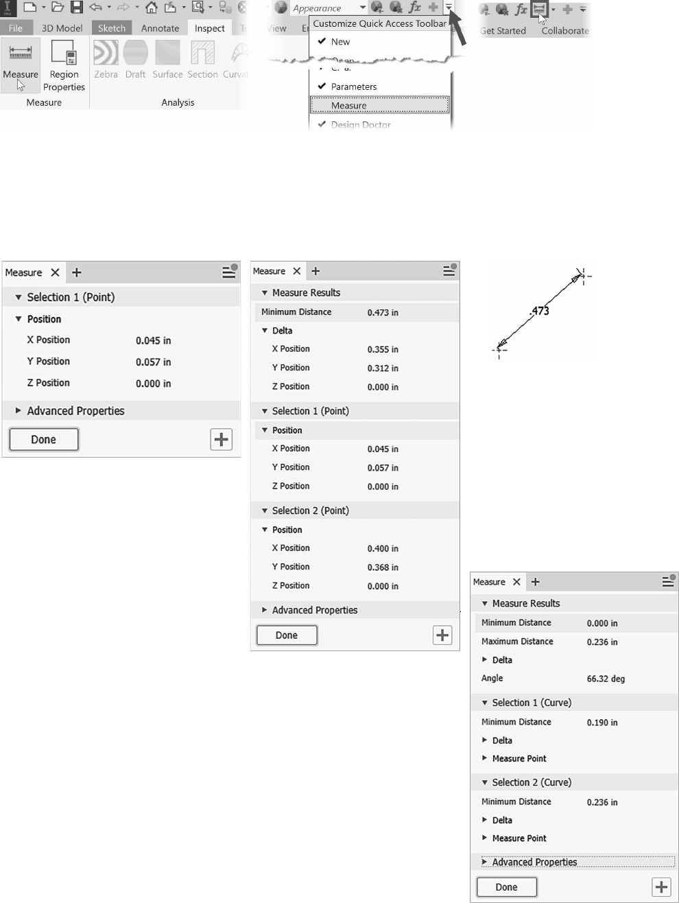
MEASURE COMMAND 73
Figure 2.77
Position and Distance Between Two Points
Select a point and the X, Y, Z position data will be displayed in the Measure tool panel as shown in the fol-
lowing image on the left. Select two points and the position data of both points will be displayed as well as the
distance between two points as shown in the following image on the right.
Figure 2.78
Length, Radius, Diameter
Measures the distance for an edge or line, diameter or radius of a cylindrical
face or circle, distance between two points, and distance between two compo-
nents in an assembly (covered in Chapter 6 Assemblies).
Angle
Measures the angle by selecting two edges, two lines, an arc, select two
points and then hold down the Shift key and select a third point, or select a
line or an edge and a planar face.
Figure 2.79 shows the results after measuring two edges.
Figure 2.79

74 Chapter 2 SKETCHING, CONSTRAINING, AND DIMENSIONING
Loop
Start the Measure command and then move the cursor over an edge and let the cursor stay still for two seconds
and then click Curve Loop from the toolbar as shown in the following image on the left. The loop distance will
appear in the Measure property panel as shown in the following image on the right.
Figure 2.80
Measure Perimeter and Area
Measure the area by selecting inside an enclosed face of a 3D solid or surface. To get area data of a closed 2D
Prole, you can also use the Region Properties command that is covered next.
Figure 2.81
TIPS: Copy measured data to the clipboard by right-clicking in the cell containing the data and
choosing Copy from the menu. ■■ To restart measure selection, click anywhere in the graphics
window.
Set Precision and Dual Units
To set the precision and display the results in dual units, click the right facing arrow to the left of the Advanced
Settings area as shown in Figure 2.82.
Figure 2.82

REGION PROPERTIES 75
REGION PROPERTIES
The Region Properties command located on the Inspect tab > Measure panel can be used to determine the area,
perimeter, and moments of inertia of a closed 2D sketch while in Sketch mode (Figure 2.83.)
Figure 2.83
Measurements are taken from the sketch coordinate system (0,0). After selecting inside a closed region, click
the Calculate button. The properties can be displayed in the document's default units or dual units of your
choice. The following image shows the region properties of a closed prole that has a void consisting of a slot.
Figure 2.84

76 Chapter 2 SKETCHING, CONSTRAINING, AND DIMENSIONING
INSERTING AN AUTOCAD FILE
You may have legacy AutoCAD les or receive AutoCAD les that you need to convert into Inventor parts. In
this section, you learn how to insert AutoCAD data into a sketch. When importing a 2D DWG le into Au-
todesk Inventor, you can either copy the contents from the DWG le to the clipboard via Autodesk Inventor or
AutoCAD and paste the contents into Autodesk Inventor, or use an import wizard that guides you through the
process. In this section, you learn how to insert AutoCAD 2D data into a sketch in an Inventor part le.
TIP: AutoCAD does not need to be installed to import AutoCAD geometry into
Autodesk Inventor.
Inserting 2D AutoCAD Data into a Sketch
This section describes how to insert AutoCAD 2D data into the active sketch in a part or drawing. To insert
AutoCAD data into the active sketch, follow these steps:
1. Start a new Inventor part le or open an existing part le.
2. Create a new sketch or make an existing sketch active.
3. Click the Insert AutoCAD File command on the Sketch tab > Insert panel as shown in the
following image.
Figure 2.85
4. The Open dialog box will appear. Browse to and either double-click the desired DWG le or click
on the DWG le and then click Open.
Figure 2.86

INSERTING AN AUTOCAD FILE 77
5. The Layers and Objects Import Options dialog box appears. In the Selective import section in the
upper-left corner of the dialog box, uncheck the layer names you do not want data imported from
as shown in the following image.
6. To select specic objects to insert, uncheck the All option, and then select the desired data in the
preview window. In the preview window, you can zoom and pan as needed.
7. You can change the background color of the preview image by clicking the black or white icon at
the top-right corner of the dialog box.
Figure 2.87
8. Click the Next button to go to the next step. In the Import Destination Options dialog box specify
the units in which the data was created as shown in the following image.
9. Check the options to Constrain End Points and Apply geometric constraints as shown in Figure
2.88. The Apply geometric constraints option will add sketch constraints to geometry that is par-
allel, perpendicular and tangent.

78 Chapter 2 SKETCHING, CONSTRAINING, AND DIMENSIONING
Figure 2.88
10. To import the data, click Finish.
11. Use the Zoom All command or double-click the wheel to see all the geometry.
12. Delete unnecessary geometry, constraints, and dimensions.
13. Add geometry (if needed), constraints, and dimensions to fully constrain the sketch.
Insert AutoCAD File with Associativity
If you want to import AutoCAD data as an underlay, which allows you to project the imported geometry onto a
sketch, use the Import command on the Manage tab > Insert panel. If the imported AutoCAD data changes, you
can update the geometry by clicking the Update command on the Quick Access toolbar.
Inventor can open parts and assemblies exported from other CAD systems. When les from other CAD systems
are opened in Inventor, they will be imported as solids or surface models depending upon the original le and
the components will NOT have feature history and an assembly will NOT have any assembly constraints.
You can add features to imported parts and edit the geometry by using Inventor’s Direct Edit command. For
les that are imported as an assembly, you can add assembly constraints.
To open le types such as DXF, Alias, Catia, IDF Board Files, IGES, JT, Parasolid, PRO/E, SAT, STEP, Solid-
Works, and Unigraphics NX, click the File tab > Open or click Open on the Quick Access toolbar.
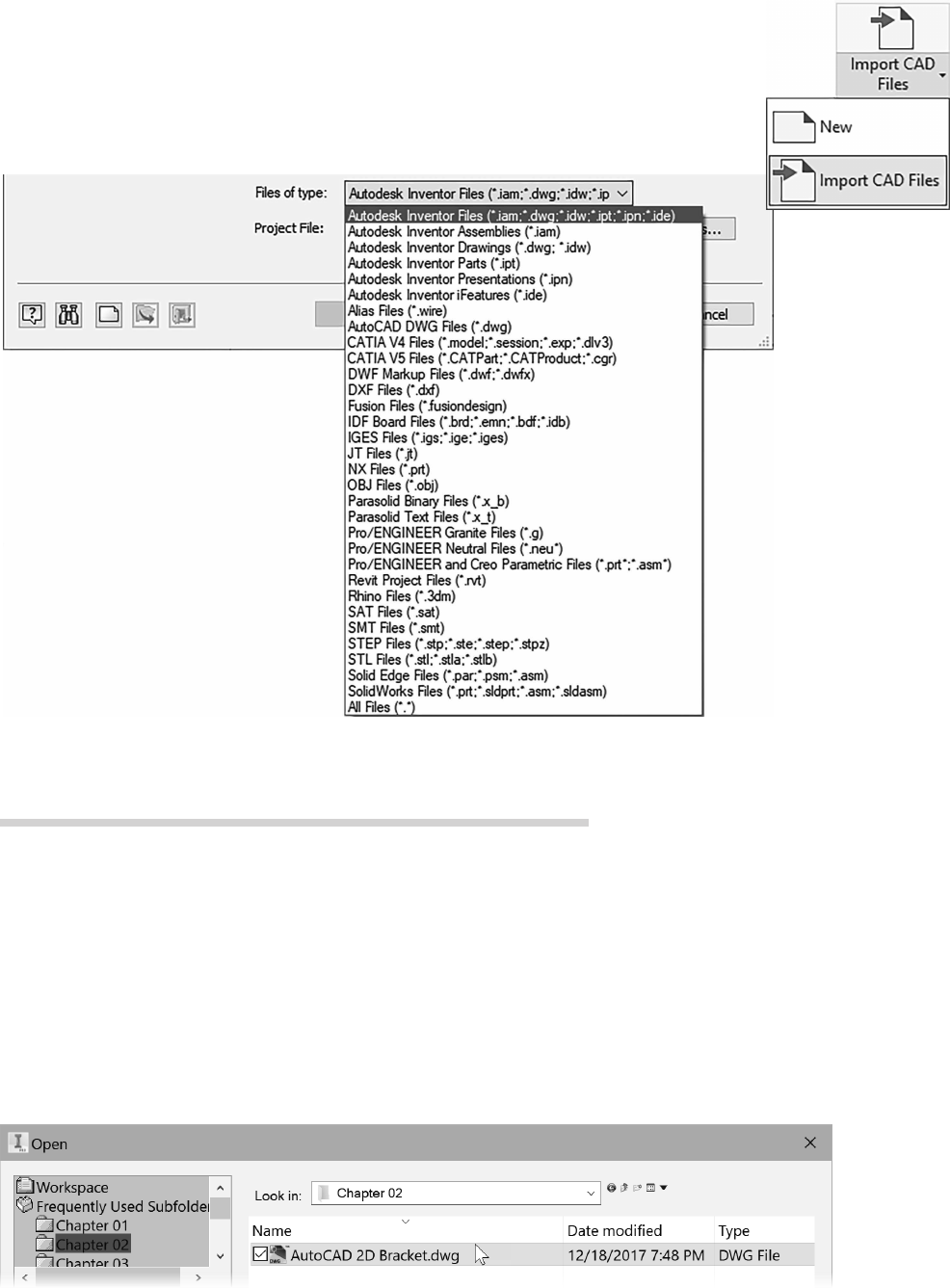
EXERCISE 2-5: INSERTING AUTOCAD DATA 79
You can also select the Import CAD Files option from the Getting Started tab or use the
Import DWG command from the File tab > Open; this command will import AutoCAD
data into a new drawing, title block, border, symbol or part le without having to rst
create a new le.
In the Open dialog box, choose the desired le format from the Files of type list. See the
help system for more information about the dierent le types.
Figure 2.89
In this exercise, you insert AutoCAD data into a sketch and add constraints to fully constrain the sketch.
1 Use the New command, English tab, and choose Standard (in).ipt, or if inch is already the default
unit, from the left side of the Quick Access toolbar you can click the down arrow of the New icon, and
select Part.
2 Click Start 2D Sketch from the 3D Model tab > Sketch panel. Select the XY origin sketch plane.
3 Click Insert AutoCAD from the Sketch tab > Insert panel.
4 From the Frequently Used Subfolder area (dialog box upper-left) click the Chapter 02 subfolder and
then in the le area double-click to choose the le AutoCAD 2D Bracket.dwg.
Figure 2.90
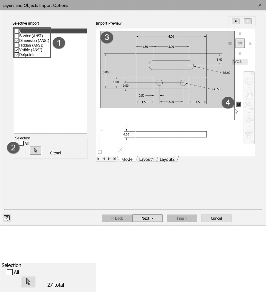
80 Chapter 2 SKETCHING, CONSTRAINING, AND DIMENSIONING
5 From the Layers and Objects Import Options dialog box uncheck the layers that are not needed. In the
upper left corner of the dialog box uncheck layers 0, Border (ANSI) and Hidden (ANSI) as shown in
Figure 2.91 (1).
6 In the Selection area near the bottom left corner of the dialog box uncheck All, labeled (2) in the fol-
lowing image.
7 Select the geometry and dimensions to insert, use the window selection– click a point above and to the
left of the geometry labeled (3) and then click a point below and to the right of the geometry labeled
(4). Note that if you click and drag you can draw an irregular shape around the geometry.
Figure 2.91
8 In the Selection area of the dialog box, verify that 27 total objects are selected as shown in Figure 2.92.
If not, reselect all the data in the top view.
Figure 2.92
9 Click Next from the bottom of the dialog box.

EXERCISE 2-5: INSERTING AUTOCAD DATA 81
10 In the Import Destination Options dialog ensure inch is set as the detected unit.
11 Check the Constrain End Points and the Apply geometric constraints options as shown in Figure 2.93.
Figure 2.93
12 Click Finish from the bottom of the dialog box.
13 If needed, display all the geometry by double-clicking the mouse wheel.
14 Apply a horizontal constraint between the center points of the two circles labeled (1) in Figure 2.94.
15 Apply a collinear constraint between the two middle horizontal lines labeled (2).
16 Press the ESC key twice to cancel the command.
17 The sketch is free to move. To constrain the sketch to the origin, drag the lower-left corner of the
sketch labeled (3) in the following image to the origin point of the sketch (0,0). Or you could add a
coincident constraint between the origin point and the left point on the bottom line.
Note that you may need to zoom out to see the origin below and to the left of the inserted geometry.
Figure 2.94
18 The lower-right of the Status Bar should show “1 dimensions needed” to constrain the sketch.
19 Drag the top-right endpoint of the upper horizontal line up. The sketch will be rotated slightly as
shown in Figure 2.95 left.
20 Apply a horizontal constraint to the lower horizontal line, and this will fully constrain the sketch as
shown in Figure 2.95 right. Reposition the dimensions as needed.
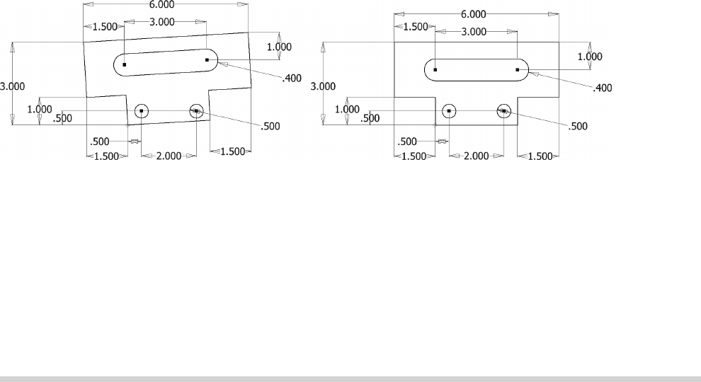
82 Chapter 2 SKETCHING, CONSTRAINING, AND DIMENSIONING
Figure 2.95 Figure 295
21 Press the F8 key to see all constraints.
22 Press the F9 key to hide all constraints.
23 The AutoCAD dimensions on the sketch are now parametric and can be edited. Practice editing the
values of the dimensions by double-clicking on a dimension’s value and enter a new value.
24 Close the le. Do not save changes.
End of exercise.
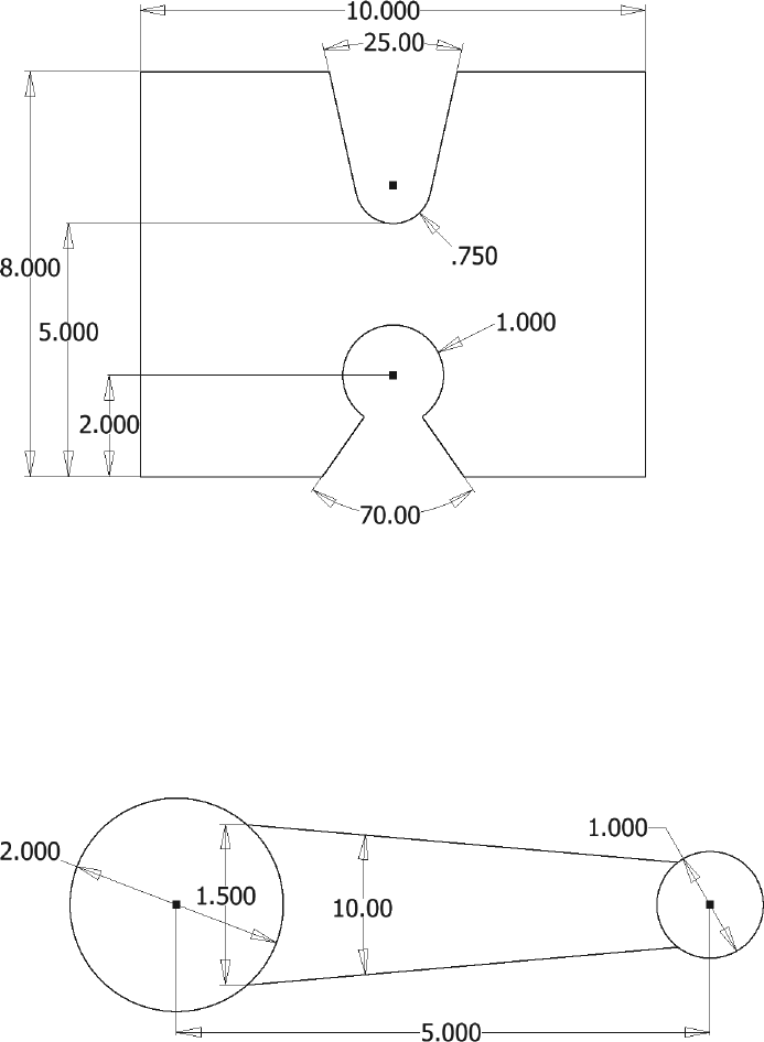
APPLYING YOUR SKILLS 83
Start a new part le based on the Standard (in).ipt, choose the XY sketch plane. Create the sketch and add geo-
metric and dimensional constraints to fully control the size and shape for the part below.
• Assume that the top and bottom horizontal lines are collinear.
• The center points of the arcs are aligned vertically.
• The sketch is symmetric about the left and right sides.
• The bottom angled lines should be coincident with the center point of the lower arc (if the arc is drawn
via the line command, the center point of the arc will automatically be coincident with the line it was
drawn from).
When done, close the le and do not save the changes.
Figure 2.96
Skills Exercise 2-2
Start a new part le based on the Standard (in).ipt template. Create a fully constrained sketch on the XY plane
using lines and arcs as shown in the following image. First sketch the two circles and align their center points
horizontally. Then create the two lines and place a vertical constraint between the line endpoints on both ends.
Add the dimensions. Check that your sketch is fully constrained. When done, close the le and do not save the
changes.
Figure 2.97

84 Chapter 2 SKETCHING, CONSTRAINING, AND DIMENSIONING
Use these questions to test your knowledge of the material in this chapter.
1. True__ False__ While sketching, by default, geometric constraints are not applied to the sketch.
2. True__ False__ When you sketch and a point is inferred, a constraint is applied to represent that
relationship.
3. True__ False__ It is recommended to never fully constrain a sketch.
4. True__ False__ When working on a millimeter part, you cannot input inch units.
5. True__ False__ After a sketch is fully constrained, you cannot change a dimension’s value.
6. True__ False__ A driven dimension is another name for a parametric dimension.
7. True__ False__ Dimensions placed dynamically are not parametric.
8. True__ False__ You can only import 2D AutoCAD data into Autodesk Inventor.
9. Explain how to draw an arc while using the Line command.
10. Explain how to remove a geometric constraint from a sketch.
11. Explain how to change a vertical dimension to an aligned dimension while placing the dimension.
12. Explain how to create a dimension that is tangent to two arcs.
13. True__ False__ AutoCAD needs to be installed to insert AutoCAD geometry.
14. True__ False__ When a sketch is extruded that contains construction geometry, the construction
geometry is deleted.
15. Explain how to change the unit type in a part le.
16. Explain where you would turn on Relax Mode.
17. True__ False__ When a pushpin appears in the Sketch entry in the browser, the sketch is fully con-
strained.
18. True__ False__ By default an arc length dimension can only be a driven dimension.
19. Explain how to draw a rectangle that is centered on the origin point.
20. True__ False__ When creating the rst 2D sketch, you must select an origin plane to sketch on.
