
Vault Data Standard – Tutorial
Chapter 05 – Inventor
Save New File(s)/Edit Datasheet, Copy/Replace
Introduction
In Chapter 01, you learned that Data Standard adds the workflow to start new files in Vault Explorer based on
vaulted templates. Inventor users may continue to start new files in their CAD application respectively. Data
Standard for Inventor supports the workflow of initial save of any Inventor file type by a customizable dialog
allowing business logic added as rules and user guidance. Data Standard uses first save events replacing the
default Save dialog by the VDS Datasheet or special dialogs for Frame Generator, Design Assistant, Tube & Pipe or
Cable and Harness assembly sub-types. VDS for Inventor adds workflows to copy or replace 3D model
components including their drawings within an assembly context.
Learning Objectives
- Learn the basic workflow options of creating new Inventor files, save and check-in to existing Vault folders
or projects (enforced/optional check-in)
- Practice advanced workflows creating new components in assembly context.
- Practice workflows using Inventor Frame Generator or Design Accelerator components
- Learn how to use Copy/Replace commands creating new components including drawings in assembly
context.
- Compare the benefits of using Save As export file command vs. default file export dialog
- Get insights on background processes and additional access points, allowing you to customize this
Inventor – Vault workflows to your company’s needs.
Training Files
You need to have installed all training files by following the instructions in Chapter 00 – Introduction and ReadMe
First.

This chapter requires access to these template files in Vault,
Exercise 2 requires access to the local files (get files from Vault):
VDS configuration files added or changed in this chapter’s exercises can be found in .\Training Files\VDS
Configuration Files\Chapter 05 – finished\.
Workflow
Data Standard for Inventor has six main workflows
1. New Part/Assembly File(ipt, iam)
2. New Documentation (idw/dwg, ipn)
3. Edit Datasheet of Existing Models or Drawings
4. Copy/Replace incl. Drawing (ipt + idw/dwg, iam + idw/dwg)
5. Save Copy As (Inventor Export Formats)
6. Save Frame Generator, Design Accelerator, Tube&Pipe, or Cable&Harness Assemblies
We should look at each of them in detail.

1 – New Model File (Part/Assembly)
1a – Save with auto check-in (default)
Saving a new part/assembly VDS shows the dialog New File:
As users commit the metadata (OK), Data Standard invokes the check-in command automatically.

Depending on the Vault Option -> Dialog Suppression setting, the
automatic check-in invokes the dialog (with the option of OK/Cancel) or
completes the file upload to Vault silently.
In the following examples, the Check In dialog suppression option
remains enabled.
1b – Save, and check-in manually
We can disable the auto check-in option on dialog close. To enable this behavior, copy the configuration file
.\CAD\Configuration\Inventor.cfg to the customization folder .\CAD.Custom\Configuration\Inventor.cfg and
change the value of ShowCheckInDialog to value False.
This configuration option closes and Inventor Data Standard dialog without further action. Users may save locally
first while matching the target folder in Vault and check-in the file on demand.

2 – New Documentation File (Drawing/Presentation)
Inventor Vault AddIn options enable or disable file number generation for drawing and presentation files:
VDS New File dialog for documentation files behave according to the option selected.
2a – Re-using model file name
By saving a new part/assembly, Documentation VDS shows the dialog New File.
In case the Vault Option disables file numbers, VDS also disables the numbering scheme selection (1) and suggests
a file name based on the model name (2):

Note – Administrators should continue to map properties from model
to drawings in the Inventor Template settings.
As users commit the metadata (OK), Data Standard invokes the check-in command automatically.
2b – Using Numbering Scheme
If the option Generate numbers… is enabled, the New File Dialog allows the selection of a numbering scheme and
hides the text box of the file name as a scheme is active (1):
3 - Edit Datasheet of Existing Models or Drawings
An existing Vault may contain Inventor models and drawings that have been released a long time before Data
Standard started supporting the workflow of driving metadata. VDS for Inventor works inline with Inventor
properties, so the datasheet gets the values of the current model/drawing.

A user also might open a model/drawing under revision and update geometry or annotations. As the
model/drawing saves, Data Standard validates the metadata silently in the background; in case of validation
errors, the Edit Datasheet shows up and enforces users to comply with updated company rules.
4 - Copy/Replace incl. Drawing (ipt + idw/dwg, iam + idw/dwg)
Autodesk Vault Copy Design Tool creates new design files by copying existing data within the context of Vault
Explorer or CopyDesign Standalone Application. Vault Data Standard adds design copy benefits to the running
Inventor session. Whenever an engineer requires a copy of a model, a drawing, or a copy of both, the copy design
action is available in the current Inventor context.
4a – Copy incl. Drawing
This workflow saves the current state of a part or an assembly
and invokes VDS Copy File Dialogs for models and drawings.
A warning message appears if the source file
current Inventor is different from the latest
version in Vault.

Data Standard uses the identical
dialog definition (Inventor.xaml)
with the New File Dialog but
behaves slightly different in details:
• The folder bread crumb pre-
selects the path of the
source file (1)
• The suggested filename
adds the prefix Copy_ if no
numbering scheme is pre-
selected (2)
The suggested new Title text value adds the prefix Copy_. (3)
The subsequent Copy File dialog for
the drawing is of similar look and
feel:
• The suggested file path (1)
reflects the path of the
copied model.
• Number scheme selection
enables/disables according
to the Vault Option
Generate Numbers for… as
for new drawing or presentation files (2)
o If the model used the prefix Copy_ the suggested drawing name re-uses the prefix
o If the model name consumed a new number, the suggested drawing name – and if drawing
names are linked to model names – the new drawing name suggestion is the new model’s file
number.
• The suggested new Title text value adds the prefix Copy_. (3)

4b – Replace with Copy incl. Drawing
This workflow is useful when the user wants to keep the current state of a part or an
assembly and continue working on a copied model within the current assembly
context.
The Replace command expects the user to select a model occurrence, then the copy model (incl. Drawing)
workflow starts as we saw in workflow 4a:
Committing the Copy File dialog for the drawing, the workflow ends; the
newly created drawing remains open, while the newly created model file
already replaced its origin in the assembly:
Note –The Data Standard command Replace
with copy automatically offers the option to
replace all, if the user selected component is one
of the multiple component occurrences.

5 - Save Copy As (Inventor Export Formats)
Inventor Data Standard Save Copy As command allows saving models to
STEP and JT, and Drawings to AutoCAD DWG, DXF, and PDF formats (1).
Based on the format selected, all export options are accessible,
respectively (2).
Users benefit from Vault Folder selection (3), the optional
numbering scheme (4), adding metadata based on the target
file Category (5), and a silent check-in of the new file on dialog
close.
Note – The check-in of these export files is always enabled and
not related to the setting in the Inventor.cfg <ShowCheckInDialog>. The checked-in export files are not attached
to the source.
6 – Assembly Component Generators
Inventor offers a collection of rule-based component generators that allow you to concentrate on functional
requirements and design parameters. All of them re-use Content Center components and automate the creation
of multiple standard, or custom parts, and require subassembly structures. Data Standard for Inventor groups all
types of these files. It helps to bulk fill metadata in specific New File dialogs for each, that is not pre-filled from
Content Center. VDS ignores singular Standard Content Center components per default.
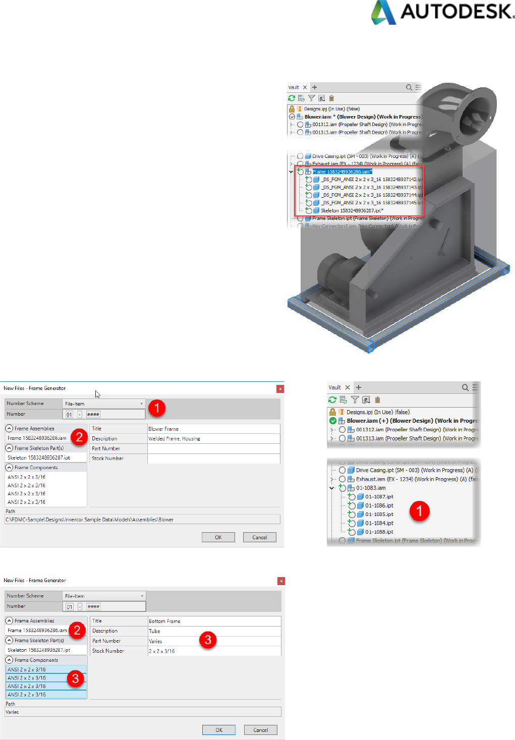
6a – Frame Generator
VDS detects new Frame Assemblies, changed or added
Frame Member files on saving events of the parent
assembly. Looking into our current sample we see a new
Frame subassembly, including the skeleton reference and
several Frame Members created.
Initiated by a save on the parent assembly, VDS lists all of
them in a special Data Standard New Files – Frame
Generator dialog (the dialog definition file
FrameGenerator.xaml locates in .\CAD\Configuration\).
The activated numbering scheme replaces all temporary file names (1) on dialog close (OK).
Users access each file type’s (2) metadata and can fill frame member’s properties based on multi-selection (3):

As we add more Frame Member components, subsequently save actions incrementally add new member files
only to the dialog; previously saved Frame Generator files don’t list again:
6b – Design Accelerator
Similar to before, Data Standard for Inventor filters new Design Accelerator assemblies and components in a
special dialog New Files – Design Accelerator (the dialog definition file DesignAccelerator.xaml locates in
.\CAD\Configuration\). In the sample shown here, we created a shaft and added a bearing and an O-Ring. VDS
recognizes all phantom assemblies (1) and custom part files, like the shaft part (2); the O-Ring and Bearing are
filtered as standard components that must not change metadata:
Multi-selection within each file type allows the filling of descriptive metadata in a single step.
6c – Tube and Pipe
Inventor aggregates Tube and Pipe routes within run subassemblies; these are the starting level for Data Standard
capturing all route parts and their components. Unlike Frame or Design Accelerators, Tube and Pipe
subassemblies ask for a file name and location before they create.
Note – VDS overwrites the file name on saving later, but does not influence the
location.

The dialog concept replicates the principles seen before: fill descriptive metadata, that is not pre-filled by Content
Center source within a single spot (the dialog definition file TubeAndPipe.xaml locates in .\CAD\Configuration\).
6d – Cable and Harness
Workflow and concept of Cable and Harness are identical to Tube and Pipe (the dialog definition file
TubeAndPipe.xaml locates in .\CAD\Configuration\).
Exercise 1 – Create New In-Place Components
During the workflow demonstrations, we saw VDS behavior for a single model and documentation files. In this
exercise we practice the usage of Data Standard in an assembly workflow for multiple new components.
Step 1 – New Assembly
Create a new assembly, but don’t save it for now.
Step 2 – Create the first In-Place Component
Continue adding a new component in the context of
the assembly. Using Data Standard for Inventor,
both, the new file name and the folder location (1), are not relevant
at this stage; the save dialog is going to override these values later.
So, select a template – in this exercise we use a part template with
modeled geometry: the BaseRing.ipt (2).

Place the model and leave the new components edit level.
For now, we have two new unsaved files. Fire the save command and always watch the
temporary file name in the New File dialogs. In this case the assembly saves first.
We select the folder Chapter 05 (; note – the
Inventor workspace folder $\Designs\ is the root
for Inventor files and does not list in the dialog
(1). The category Engineering is pre-selected,
and you might expect, that the numbering
scheme Engineering also activates as we learned
for Vault Explorer in Chapter 01. The numbering
scheme aligns as soon as you change the
Category, e.g., flip to category Office and back to
Engineering (2). The numbering scheme reacts to
the change category event and the pre-selection
in the dialog initialization prevents it. We are
going to discuss event handling and pre-selection in Chapter 10 (Programming section) to solve both
requirements. Fill Title and Description (3) and commit the Dialog (OK).
Inventor displays the known assembly save-listing and we can
expect that Part4.ipt is the next file to be handled by Data
Standard.
Again, select the folder Chapter 05, numbering
scheme Engineering, and enter metadata (1)-(3).
Inventor Material selection list populates to the
dialog; if we select another material, e.g., PC
Lexan - smoke, the material updates on Dialog
close (OK).

Step 3 – Create a second In-Place Component
Repeat the steps to create another In-Place component and select the tutorial template Flange.ipt. In this case,
save it (2), before you leave this component’s edit level (1):
Now, Data Standard activates the folder
Chapter 05 automatically as a suggestion of the
last used folder (1).
Note – Watching the Vault Browser, you may encounter a situation that a new In-Place
component displays like a suppressed component. Refresh the Browser to update the
view.
Step 4 – Add Component from Vault
Many users prefer
having Inventor and
Vault Explorer side by
side on dual screen. For
this scenario, Data
Standard adds another
productivity benefit by inserting components from the search result or list view into the current assembly.

We don’t have too many components yet in our training
Vault. At least, we can search for the “Flange” that we
created lastly and insert another instance to follow this
approach.
Data Standard hands over to Inventor and the new part is
at the cursor as known
for Inventor Place
Component procedure.
Exercise 2 – Skip Vault Data Standard
Users may want to skip Data Standard dialogs on save events. There are various reasons for doing this:
• The usage of 3
rd
party library for purchased components. The library populates completed metadata and
there is no reason to interact for user input on save.
• Many imports of larger assembly files in 3
rd
party file formats. Instead of saving all files interactively one
by one, you may prefer saving all, and bulk edit all metadata later.
Data Standard configuration shares an option to recognize files not to be handled based on properties. 3
rd
party
library files usually share a custom iProperty containing the vendor information. For import files, Inventor
generates a custom property Sending System to store the originator of the imported geometry.

Step 1 – Import 3
rd
Party Assembly File
Open the file .\Chapter 00 - Introduction
& ReadMe First\Training Files\Local
Files\Chapter 05\ Projector - Wintech
PRO4500.sldasm.
Select the Convert option:
Note - Reference Model Option results in a single Inventor
assembly file with associative internal components; so, there
is no risk of interacting with multiple VDS New File dialogs.
Don’t enable the option Reduced Memory Mode before you disabled VDS for
import workflows.
File Naming and location options are not relevant as long as
Data Standard interacts for each imported file. It changes
later as we are going to disable the VDS interaction.
Complete the Import saving all files to Vault selecting the folder Chapter 05, the numbering scheme Engineering,
and adding text to the Title field (required to enable OK):
The Save Dependents dialog is like an announcement on how many
VDS New File dialogs are following; so, this is the last option to stop
and configure to skip for imported 3
rd
party file formats first. Be
prepared for another 6 New File interactions if you proceed.

Step 2 – Configure VDS Inventor to Skip for 3
rd
Party Imported Files
As mentioned before, Inventor 3
rd
party import adds a custom property Sending System to each file. Use this
property to register 3
rd
party imports for skipping save events in the file Inventor.cfg. To this copy the file
.\CAD\Configuration\Inventor.cfg to the customization folder .\CAD.Custom\Configuration\Inventor.cfg.
Edit the file and add the property name Sending System to the node <SkipForProperties> as shown below:
Restart Inventor once you saved the configuration file.
Step 3 – Repeat Import and Save of 3
rd
Party Assembly File
Repeat the import of the file .\Chapter 00 - Introduction & ReadMe First\Training Files\Local Files\Chapter 05\
Projector - Wintech PRO4500.sldasm – but now, select a matching local folder in the options like shown:
The Save Dependencies dialog lists all original file names
and saves without any further Vault interaction.

Note – If you unloaded Data Standard for Inventor instead, the Vault Numbering interaction initiates:
We recommend using this configuration option as a default if you frequently import larger 3rd party file formats.
Once the files are in Vault, a bulk property edit to transfer original file names to the Title field and a subsequent
rename action might outperform the timely effort to fill all data sheets one by one in Inventor.
Configuration Insights – Data Standard for Inventor
All Inventor Data Standard workflows have several access points for customizations. Table 1 below refers to New
File/Edit Datasheet workflows triggered by saving events. It lists involved configuration files, functions and refers
to other customization tasks.
Table 1
If an assembly file contains Component Generator subassemblies like Frame Generator additional VDS dialogs
initialize and display for user input. It happens for new component files only. Edit Datasheet commands on
existing components works, as shown in the table before. Table 2 lists involved definitions and scripts for
Component Generator files:

Table 2
The Inventor Data Standard Commands Copy/Replace follow the path documented in Table 1.
The Save Copy As command uses an individual dialog definition requiring additional selections for Export format
and options. Note – the options dialog is part of the core Inventor and called for display/input only. Review Table
3 for details on it.
Table 3

Data Standard for Inventor – Add-In configuration
Save events are triggered by individual commands. VDS differentiates a save triggered by the Save button (=
CTRL+S) or a save event triggered by an In-Place workflow like mirror, assembly copy, or productivity commands.
The default configuration set various commands to each. These should not remove for the sake of compatibility.
Administrators can disable additional commands
and replace VDS dialog interaction by the Vault
numbering scheme selection only. The Help
Documentation shares steps to adjust the Add-In
configuration.
• Disable Data Standard for commands
• Enable Vault Numbering for commands
Example – Disable VDS for Frame Generator
We can configure Data Standard for Inventor to default Vault Numbering dialogs without editing metadata. The
resulting workflow on a new frame initiates two dialogs allowing
numbering selection for the frame assembly and skeleton and
another for all frame members.
Add the command AFG_CMD_InsertProfile to the nodes <EnableVaultNumSchemeForCmds> and
<DisableVdsForCmds> as shown below to enable this behavior. Find a list of available command names (Inventor
2020 including Add-Ins) in the training files .\Training Files\VDS Configuration Files\Chapter 05\
INV2020_CommandNames_inclAddIns.txt.
