
Page 1
MFG317090
Getting the Most Out of Your Inventor Templates
Mark Lancaster
Synergis Engineering Design Solution (EDS) – Autodesk Reseller
Description
Inventor templates play an important role in your organization and design processes. So
important, I believe that a properly configured template is more valuable than your designs.
Learn about the four important pillars of an Inventor template, and see if your templates are
strong enough to hold up to your requirements.
Speaker(s)
Since 2013, I’ve been the Product Support Specialist/Help Desk Tech for Synergis Engineering
Design Solution, a gold level Autodesk reseller located in Quakertown PA. My support focus is
centered on Autodesk manufacturing & data management solutions along with Autodesk
licensing/subscription & Autodesk Account management. Although my certification recently
expired, I’ve held the Autodesk Certified Inventor Professional for the past 5 to 6 years, been an
Autodesk Expert Elite for over 3 years now and recently became a certified Autodesk instructor.
Besides assisting Synergis’ customers with product support issues, I also spend time out on the
Autodesk Licensing/Installation & Inventor forums assisting other user like yourself. In addition
I’ve been awarded 2 years in row for being one of the top three contributors in the Autodesk
community and forums. Have also hosted (or as a co-speaker) sessions at Autodesk University
since 2016.
Although most of my career has been focusing on CAD and document management
administration/support, I’m no stranger to the CAD world. I started out (late 80s) by performing
drafting/design duties using a (drafting) board and CAD software. I have over 20 years of
experience in the manufacturing world, 15+ years in the 3D modeling world, and a self-taught
AutoCAD user since Release 9. My motto for many years has been “I’m here to assist you in
getting your job done” and I’m always looking for better ways of doing things due to my “Lean
Manufacturing” background.
Learning Objectives
Discover what’s provided with the installation
Learn how to develop an implementation plan
Learn about the four (4) important pillars of an Inventor template
Learn what to include in your templates

Page 2
A simple definition of a “template” is something that serves as a starting point for others to use
or to copy from. In Autodesk Inventor and majority of other types of applications we may use,
when we start something new, we’re starting from a template, whether that may be a blank file
or something that contains preset information. “Templates” have been around for many years
and are used for many purposes.
For me, starting out in the design world on a drafting board, it was important to have those
individual “drafting templates” (or drafting tools) to assist in
getting the hand drawings completed. For CAD we really need a starting point (our templates)
and then build from there using the internal CAD tools. Which leads me to my first question…
Will your current Inventor templates withstand your requirements?
For years being a CAD and document management administrator I have invested a lot of time in
ensuring our related templates did just that (withstand our requirements). For me I’ve always
ranked the templates high on the list and I actually believe they rank even higher than the
designs, models or documentation that’s created from them. In my opinion, having an excellent
starting point for your designs will most likely make your design life much easier. Although I’m
no longer a CAD administrator, in the past, I would consider our templates as being like an
encyclopedia filled with a wealth of knowledge. Can you say that about your templates?
Before we get into building and understanding the four (4) supporting pillars of our Inventor
templates, let’s talk about what’s provided when Inventor is installed. When an Inventor version
is installed on a given machine, the default templates are stored here
C:\Users\Public\Documents\Autodesk\Inventor <version>\Templates. But this location can
be changed later through the Inventor application options or the current (active) project file.
Inventor 2018 and prior: In the image below, a factory folder exist since the factory design
utilities was also installed for Inventor 2018. With 2017 and newer, templates for 3D PDF
creation are also provided.

Page 3
Inventor 2019: In this example, the “Nesting Utility” was installed and being used.
Inventor 2020 (EN-US version): Depending on the installed or defaulted language pack you’re
using, the en-US (“English”) sub-folder shown in this example may be designated as another
language subfolder.

Page 4
When we compare the “New” dialog within Inventor to the location of our templates in file
explorer, we can see the relationship between the dialog and the location specified.
So how did we reach this point? How did Inventor actually know what “standard” templates I
needed? Let’s rewind and go back again to
when Inventor was installed. In earlier versions of Inventor we would expand the configuration
Page 5
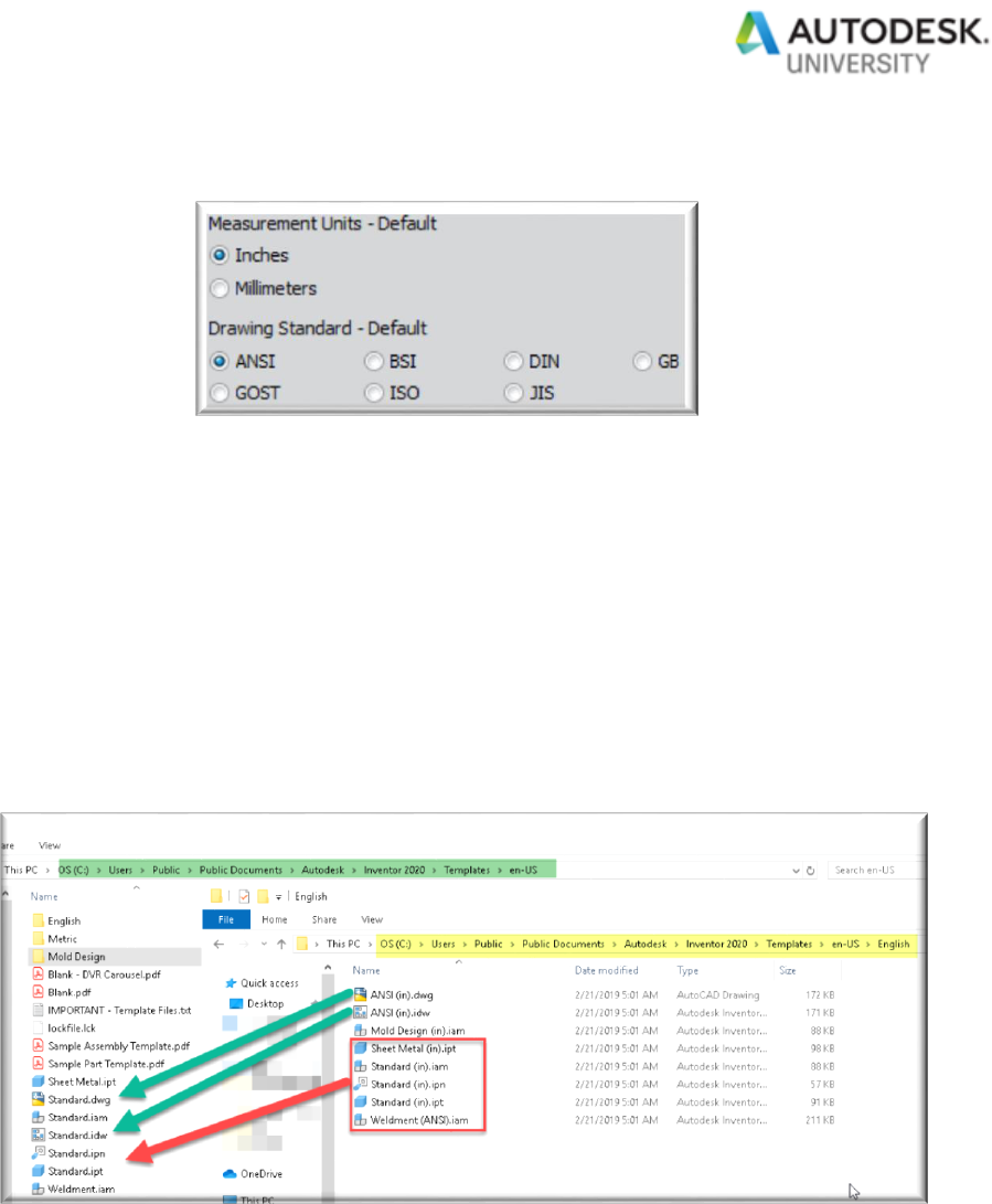
options of the installer and select what “default”
standard we would use for our templates. From there, Inventor would configure our default
“template” folder structure based on the selected standard. Now-a-days, Inventor will default
based on the language pack being installed and used. For example if I was using the German
language pack, Inventor would default to the DIN mm standard. In the end the standard
selected via the installation process may not end up being what you need, but it can be changed
later (and we will cover that shortly).
For my Inventor 2020 installation, using the English language pack, the ANSI or English version
standard is copied (“standard” templates) over from the “English” sub-folder to the
C:\Users\Public\Documents\Autodesk\Inventor 2020\Templates\en-Us location. In addition
the installation copies & renames the ANSI (IN) “.dwg” and “.idw” to the related “standard”
drawing templates and it processes a few other items as needed.

Page 6
When we elect to start a new document using these options under the Inventor file menu
or via the quick access toolbar (QAT)
, the related “standard” file type
is automatically used. Which
leads me to a few questions I often hear regarding this automatic use of the “standard” named
templates.
I have my own named/defined templates, how can I get Inventor to use them when I
select these options under the File menu or QAT toolbar? In order to use this functionality
with your defined templates, you’ll simply copy (or rename) your templates through File explorer
to those designated file names (Standard.<file type>). An alternative method is to use the Save

Page 7
As/Save Copy As Template function and save using the
“Standard” naming convention/location.
We never use or modified the “Standard” defined templates, can we get rid of them?
Yes and no. For Inventor part, assembly, and presentation files, if the related “New” function is
used through the file menu or QAT (toolbar) and there’s no related “STANDARD” template
present, Inventor uses an internal code to start your file as a blank state configuration. When it
comes to a drawing, the “STANDARD” must be present or you will see this
and
We always use the “standard” template concept through the file menu or QAT toolbar but
there’s time when we want to start a new file using a clean or blank state. Or we just
want to create a new file using a blank template and not start one based on our standard.
Is there a simple way of accomplishing this? Yes, if you press <CTRL>+<SHIFT> and
select the new button as shown here or from the QAT toolbar
, you’ll see this dialog . Select the
associated file type you’ll need and a new file will be created based on a blank template.
Now later down the road if you want to change what template “standard” is being used, you can
accomplish this in two (2) ways.

Page 8
Method #1: Tools/Application Options/File tab
Method #2: Inventor Home Screen/Advanced (options)
From there we would select the new “default” standard
that will be used. Just like what I’ve already
covered under the install portion for our default standard, when selecting the ANSI/Inches
options here, Inventor will basically do the same thing and copy the required information from
the “English” sub-folder to the C:\Users\Public\Documents\Autodesk\Inventor
2020\Templates\en-Us location.

Page 9
If I had selected metric as my new “default” standard, then the related metric standard would be
used
to configure the C:\Users\Public\Documents\Autodesk\Inventor 2020\Templates\en-Us
folder location. This switch will prompt
its going to replace and
backup your current structure to the “OldTemplates” folder. If you select “Cancel”, it reverts
back to prompting what standard you’ll want to use. Although we’re going to discuss the
“Tools/Application Options” or “Project File” aspect later on regarding our templates, if the
Inventor application options or active project file redirects where your templates are stored, this
switch will configure that given location and not the default location as I just mentioned a few
seconds ago.
I’m firm believer that templates play an important role in your organization and the designs that
will originate from them. Spending the extra time in developing your templates will be

Page 10
beneficially to your organization and users. Even before you can get into the development or
creation state, you really should start with a discussion followed by a plan or roadmap in what
you’re going to achieve. From there you can measure your success and adjust as time passes.
So how do we accomplish this?
Start off by having a discussion or brainstorming session in how your templates will be setup,
configured, and managed. I know from my experience as a CAD manager or hearing from
others, developing a template without input (from others) will most likely lead to negativity or
pushback from the end users. Granted if you’re 1-man show that’s different, but when
numerous end users or departments are your “end customers”, then their input is crucial and
they’re more willing to accept if they feel like that have contribute to the development of them.
Who should attend?
Members for the CAD/Engineering department
Related department managers
Purchasing/Procurement
MFG/Shop floor personal
Quality Control (QC)
IT/IS – Computer/Network support department
Sales
Your actual end customers
No, I’m not saying that every CAD user, engineer, managers, shop personal, and etc. needs to
be included in this discussion but you should at least include 1 or 2 from these departments or
have a cross range group of individuals.
Once you have the initial discussion under your belt you can start developing the roadmap
that will outline what your plan is, how it’s going to be
done and when (the timeline). This roadmap should contain the phases and milestones in
order to measure your success, thus allowing you to grow from it and adjust as needed for your
future. Some may feel this is an unnecessary step and could be skipped. For example, at my
last job when I developed our Inventor template roadmap, a few in our CAD community
including some managers’ felt this way. Later on, they realized our roadmap ended up being
useful in measuring our success and also pointed out some crucial minor configurations that we
never thought of. So yes I believe a roadmap is still an important step in your template success
but you’ll need to decide if it’s important to you as I thought.

Page 11
In the end, whether you developed an in-depth roadmap, a quick overview (roadmap) or just
end up not doing one at all, the key here is not to jump right into developing of your templates.
It’s better to take those smaller steps, create some sort of plan and by no means swing for the
fences or try to do everything that everybody wants.
A few more key bullets to consider before we move on:
• Start with what’s provided.
• But always, and I mean always, create a backup!!!!
• Don’t over-complicate the matter
• How are you going to manage your templates
• Keep it organized
A couple of times I’ve referenced the four (4) supporting pillar aspect of your Inventor templates.
What are these four (4) supporting pillars? Now this is my way of teaching others about
Inventor templates and it’s not something that’s documented in any Autodesk article or help file.
I believe these four (4) pillars are the supporting foundation of your templates and they work
with each other to support your templates. Much like pillars on a front porch supporting the
roof.

Page 12
The main learning aspect of this AU class is the first pillar or the “Definition” pillar (“what to
include” learning objective) of your templates”. Although an important pillar, I first want to focus
on the other three (3) pillars, “Location”, “Application Options” & “Project File” and then revisit
this first pillar. But before we get into any of these supporting pillars, please note, any of these
supporting pillars are not instructing or forcing you to use a certain configuration or method.
Location:
We’ve already kind of discussed the “default” location of our Inventor templates and although
the location & layout is up to you here are some recommendations on this matter:
Leave the original location and information intact: I’ve never been a fan of
modifying or changing the original provided information. Yes I may copy from and use
the copied information, but I never touch or modify the original files and/or structure
that’s provided. I always use it as my safety net or backup source.
Vault workspace, local, network (shared location): No matter if the location of your
templates is under your Vault workspace, somewhere stored on your hard drive or in a
network/shared location, the important part is to ensure it’s properly locked down from

Page 13
“on the fly” editing. Templates are still considered a controlled document in my opinion
and their access (read/write) should also be controlled.
Numerous templates/sub-folders: Now each one of us will view our templates and
the related structure differently than someone else. What works for you may not be a
solution for someone else. As we get into the actual “definition” of our templates you
will realize quickly there are many different configuration possibilities and it may seem
that I’m pitching all these different types of templates and structures. In no way am I
stating that. It is important to keep your overall template structure in a simplified
interface thus allowing it to be easily managed.
Application Options & Project File:
Much like all four pillars are needed to support your Inventor templates, the pillars of
“Application Options” and “Project File” may act like a sub-assembly in an Inventor model.
These two (2) pillars may work together and separately in order to support the overall structure
(assembly) of your templates.
In Tools/Application Options/File tab, there’s a field to define where your “default” templates are
stored and a button to
redefine what standard will be used. For Inventor 2020, if you do change the location in the
File tab and don’t include the %Language% variable in your re-directed path, the language sub-
folder or language pack will no longer be considered.
In your active Inventor project file or any other Inventor project file, under the “folder options”, a
field designates where your “project” templates are

Page 14
located. Are you now saying there’s default templates and project templates, where do my
actual templates reside? This is a great question and sometimes these separate options can
be confusing or misunderstood. Let me explain…
Up to this point I’ve been referencing templates as the “default” ones and yes when you install
and launch Inventor, you are initially using the default templates that come with Inventor. But
by no means is this limited to that concept or wording of “default”. Consider any of your
Inventor template as being “default” and/or “project” based. It all boils down in how you’re
managing the location (pillar) of you defined templates. What do I mean by this?
In the project file image above, denoting the “Folder Options” of a project file, you can see the
value of templates is set to [Default]. This is when the “Application Options” and “Project File”
pillar work together to support your Inventor templates. When set to default, it uses the location
as specified in the Application Options/File tab. In this project file example
there’s a location defined for the templates. Meaning
for this given project file (when active), it will over-ride the Inventor Application Option location
for your templates and use that location for your templates. Although technically the “Project
File” pillar is solely acting on its own and the “Application Options” pillar at this point is not really
doing anything, I still consider both are working independently to support your templates.
So there could be times when you want to use templates based on your Application Options or
other times you’ll want to control it via the active project file. You have to decide which
configuration method works for your organization and/or the types of projects you have. For me
and coming from a Vault environment, I always left the setting for templates in Application
Options as is and used the Inventor/Vault project file to control the location of our templates.
Again you have to decide which method works for you.
Now that we have covered 3 of the 4 supporting pillars, let’s turn our attention to our final pillar,
which is the main focus of our last learning objective. Although this pillar holds a lot of weight
supporting your templates, this pillar may be an easy task for you to accomplish or more
involved based on your requirements. As we go through these specific details, there’s going to
be a certain percentage of items you have already incorporated into your template and that’s a
good thing. Hopefully I will cover a few other items that you never considered or thought of and
this entire sessions turns out to be useful to you.

Page 15
But before you do anything with defining our templates, what should you do first?
Yes the key here is to backup or have a backup of the
original template structure prior to modifying or
creating your own structure or templates.

Page 16
PART (.ipt) template
For the part template, including commonly used sketched blocks, sketches, and features in your
template may be useful. Or perhaps you always want to start your parts with certain or all origin
work planes, axis, or center point visibility (on) enabled. Have you considered commonly used
view definitions that you always use or could use?
Although it’s not technically consider an Inventor starting template, a user I supported at my last
job simplified their sketching needs by creating a commonly used sketching template in a
separate part file that they could open and copy from
Maybe you consider your top and/or front view orientation differently than what’s provided.
Perhaps you would want to redefine the orientation via the View Cube for your template
configuration.

Page 17
What about commonly used fx user parameters or a link to a spreadsheet (or spreadsheets)
that can be used to control your part design or design parameters.
Do you need special lighting configurations or perhaps restrict what lighting (style) your end
users could use? What about text styles or styles (Inventor 2018 or newer) for your 3D
annotations? Are there special ones you want to configure & use or again control which text
styles they have access to in your templates?

Page 18
“iProperties” are a poweful tool within Inventor and play a big role in your Inventor files and
designs. Having them predefined like using forumlas, creating your own custom iproperties or
setting the default material will definitely be a big time saver and be useful to your users.

Page 19
But that doesn’t mean you go over-board with your iProperties and complicate the matter either.
For example at my last job and initial feedback from my users, they determined we needed to
convert numerous AutoCAD 3D block attributes to custom iProperties. In about 3 months
timeframe I noticed these custom iproperties were not even being used or filled in by the user.
In another round of discussion with them, it was actually determined they were not necessary at
all.
As I stated earlied, templates are still a controlled document. If you use Autodesk Vault to host
your templates and provide revision control from them, that’s a great way to ensure your users
are using the latest template information. Outside of Vault, that might not be as easy to
manage. However I recommend no matter how you manage your templates, is to include a
custom iProperty that denotes the template version. Or something like this

Page 20
From a CAD Manager aspect when troubleshooting, I know this template has been updated for
use in Inventor 2018 and has gone through at least one change. It also helpful when
troubleshooting existing components and I know exactly which template was used when the file
was started.
I believe one of the most over-looked configuration aspect for any of your Inventor templates is
the Tools/Document settings interface. For parts…
STANDARD tab
1. What default active lighting style do you want to start with?

Page 21
2. If Tools/Application Options/Display tab – Appearance
is controled by the document settings,
what should be your standard for
your template?
3. Should parts always start out with the “Generic” material type or some material that you
commonly use?
4. New for Inventor 2018 and if you’re into creating MBD (Model Based Defintions) or 3D
Annotations on your parts, what standard should be your default?
UNITS tab

Page 22
How are units, precision and related options handled in your templates?
SKETCH tab
Although I’ve never had a need to define the snap spacing or grid display options in my part files
or even be concerned about its line weights or the auto-bend radius settings for 3D Sketches,
but you may. So don’t overlook this tab and its settings.
MODELING tab

Page 23
The “Modeling” tab covers different aspect & options and each one of use will configure this tab
differently to suit our needs. However the ones highlighted in the above image are the settings
I commonly tell users to consider when setting up your templates. If you’re dealing with a
mixture of smaller to medium to larger sized components, you may want to consider different
part templates with specfic “Intial View Extents” in order to compensate for that first sketch
viewing aspect.
BILL OF MATERIALS tab
One of the items I often hear on help desk is I didn’t really know there were different Inventor
BOM structures or what they accomplish. In my opinion this given tab of your document
settings is an important item and should never be overlooked. Now if you don’t know what each
BOM structure does or offers, you can review my blog article >>here<<.
Again this tab may lead to different part templates that host different BOM structures. In fact at
my last job we had separate part templates for starting our normal part designs, frame generator
skeletons and others to support the creation of content center components due to the BOM
structures we required. Yes there’s more templates to manage but what did I state in
beginning? “Having an excellent starting point for your designs will most likely make
your design life much easier”. When a user at my last job needed to start a given part, they
selected the related template and they were ready to go. No need to think about what
properties, BOM options and settings were needed each and everytime.
DEFAULT TOLERANCE tab

Page 24
In my case and experience, strict or controlling tolerancing aspect or defined tolerance needs
was not really necesssary due to what the company was producing. But tolerancing may be a
big part of your designs and this tab shouldn’t be overlooked.
Granted materials and appearances are really considered a global function, part templates
could contain locally stored materials and/or appearances. When stored locally, it is
considered the document cache material or appearance information. This information, infact
may never match the global information or doesn’t even appear at all within the global material
and appearance libraries that you have defined.

Page 25
When it comes to this aspect you have to decide if the part template should host the information
or should the info reside in the global material and appearance library you have outlined in your
active Inventor project file.
Finally, this section went into details regarding your Inventor part templates, however these
settings or some of these settings should also be considered under your assembly, sheet metal,
presentation, and weldment type of templates.
Assembly (.iam) template
Although Inventor assembly file share the same items that we’ve already covered under the part
template section, this file type still has specific information that you must considered for your
assembly templates.
Like you may want to consider enabling the visibility of your origin work planes, axis and origin
point. Or perhaps defining standard assembly folder structures or including those virtual
components you use over and over.

Page 26
Speaking of virtual components, perhaps you would instead want to setup your standard virtual
components using Microsoft Excel and iLogic.
Do you create assemblies based on certain “Level of Details” (LOD’s), “View Representations”
(View Rep’s) or “Positional Representations” (Positional Rep’s)? If you do, include them in your
template to ensure they are ready to go and formatting the same way for everybody.
Just like with the part templates, consider fx parameters, styles, iProperties, and document
settings for your assembly templates. Speaking of document settings, for assemblies, consider
these options outside of what I’ve already covered under the part section

Page 27
For assemblies, I think this section is oftened overlooked and I will admit I had forgetten all
about it while configuring our templates at my last job. What am I referring to? The Inventor
Bill of Materials…
What BOM structure do you want to enable along with its viewing properties?
Columns (standard and custom iProperties) to be included (or not included) and the order (drag
column header) in which they should occur.

Page 28
Do you want part number (row) merging to occur by default or not?
Weldment (.iam) template
For the weldment template aspect, we’ve pretty much covered the settings you may also want
to consider this as well. In your weldment template you could define the weldment material that
you often use by right mouse clicking on weld/selecting iProperties/Physical tab

Page 29
Or define how the weld appearances will look under the Weld Bead tab
Perhaps you will want to predefine certain information under the prep, weld, and machining
section of the weldment browser
Under Tools/Document settings/Standard tab, don’t forget the default weld standard that would
be used for your 3D annotations (Inventor 2018.1 or newer).

Page 30
Sheet Metal (.ipt) template
For proper operation of Inventor sheet metal, we’ll know that we have to take our sheet metal
fabrication practices, materials & rules and develop the styles and standards that will be used in
our sheet metal parts. I even debated about adding this section because without this your
sheet metal parts are not properly configured. So I’ll be brief with two (2) images…

Page 31
This >>article<< is about learning the basics on sheet metal defaults.
iLogic and Inventor API Interface
No there’s not an actual iLogic or Inventor API template but these two (2) interfaces should also
be considered as part of your templates that you’re developing. For the iLogic side of it, will a
given Inventor template host a local iLogic program or will the iLogic program be accessed
through the global iLogic interface. For example here’s a drawing template containing
numerous local iLogic rules.
Although this example shows locally defined iLogic snippets, you have to determine if it’s best
for you to define them locally or globally.
What about your iLogic event triggers? How should they be handled in your templates or
perhaps you don’t require any at all?

Page 32
Although this is more of a global Inventor consideration and not really a specific template
aspect, you should still consider protecting yourself from malicious iLogic code through the
related security options or as outlined in this blog article.
For programs created through the Inventor API, I haven’t accomplished this so I have no input
to share with you. But if you do this type of programming then make sure to include this in your
template scope as needed.
Before we get into the drawing aspect of our Inventor templates, I wanted to finish up this
portion of your template definition by stating I don’t always view templates as just as being a
part, assembly, sheet metal, presentation or weldment type of file. Templates in my opinion
can cover a wide range of useful information or based on a given workflow within Inventor.
Here are some other things you may want to consider under the template definition pillar.
Presets for tapped holes and other Inventor functions using the preset option
iPart/iAssembly
Content Center component creation
Frame Generator Skeleton
iFeatures
Design Data related section
o Routed System/Tube & Pipe Styles
o Cable & Harness
o Design Accelerators
o Import Properties
o Thread/Clearance Hole table
Create Component (from assembly)
Create Parts (from selected solids)
Create Assembly (from multi-solids)
Shrinkwrap Model
Derived Parts

Page 33
Model to 3D PDF (Creating your own 3D PDF templates)
Drawing (.idw or .dwg) template
When it comes to the drawing template or teaching others in how to setup their template for
drawings, I like to start off with the four editing layers of a drawing template. No I’m not
referring to actual drawing layers or something like the layers in an AutoCAD drawing. The
editing layers I’m referring to is how an Inventor drawing is broken up into four (4) sections
(layers) that you will be defining for your template.
Layer #1: Drawing Border
This editing layer is really broken up into two (2) sections, the sheet size of your drawing and
the actual border definition. First I would start off by defining your sheet properties, such as
sheet size, the location of the titleblock and etc.

Page 34
From there we need to define our drawing border. For me I like to start with a clean slate and
not use what was provided. I can do this a couple of ways. I can either select the current
border to be deleted (right mouse click) or I could use the <CTRL>+<SHIFT> function (as
outlined earlier in this handout) to start a template with a blank state.
Under the existing drawing resources I could edit the “Default Border” information even if it
meant my requirements. But I’m a big fan of creating my own named/configured border and
leaving the original info intact for a safety net. Right mouse click on Drawing
Resources/Borders and . “Define New Border” allows you to create
your own border by using sketching functions. “Define New Zone Border” creates a pre-
defined border layout based on the input parameters via the dialog as shown here:

Page 35
. No matter what option you select for defining your border,
we’re only defining the border layout at this point. Many times users will also try to define
(sketch) their drawing titleblock definition under this step and this is not the editing layer for it.
Finally, don’t forget to insert your new defined border into the drawing sheet info.
Layer #2: Titleblock
Depending on your clean slate status or how you started defining your border editing layer, you
may need to delete (right mouse click) the existing titleblock from the overall drawing template
configuration For the actual titleblock definition, I prefer creating

Page 36
(sketching) my own named/configured titleblock but it’s up to you
if you want to do this or edit the existing ones.
Here’s some things to consider when creating your titleblock definition
The sketch of the titleblock can be anywhere on the screen and doesn’t need to be
defined in the actual corner where you have the titleblock residing
You can copy/paste, insert a block or information from AutoCAD or create the titleblock
definition from scratch. Which leads me to a question I often here… I already have my
drawing titleblock defined in AutoCAD, can I just use that? Yes you can but I always
recommend to take the extra time in creating it from scratch in order to have a
clean plate and not carry over any unwanted AutoCAD information that I may
never use.
Don’t have entities outside the envelope of your titleblock. Entities that may be floating
out in space or exist beyond the titleblock geometry could impact the automatic
placement of your titleblock in relationship to your defined border.

Page 37
Define the annotations, constraints and location of your information. However not
everything needs to be dimensioned or constrained and in some cases too many
annotations and constraints can lock geometry down that you’re trying to locate.
Create using normal Inventor text entities, iProperties, prompted entries, and with
images. Although I recommend not having linked images, you have to decide how you
want to manage your images when you bring them in
Remember anything that you do here, can only be edited or modified at this layer.
Don’t forget to insert your drawing titleblock back into the drawing.
Layer #3: Settings
We could have an entire session on the drawing template setting aspect but we don’t have the
time to go into depth about it. However my good friend and Autodesk Expert Elite associate
Chris Brenner and I hosted a >>class<< at Autodesk University 2 years ago on this exact
subject matter. For this session I will briefly go over the aspect of setting of your style.
When we look at the drawing styles and its settings, the key here is understanding this interface
and not set out to create style conflicts with your drawing templates. Again we could spend a
great deal of time on this section but as an overview, we’re basically defining the individual local
styles (meaning they only exist in the drawing) and then defining are overall standard and the
default (which individual) style that will be used when we select a given annotation function.

Page 38
More in-depth information about this interface can be found >>here<< and also I would
recommend that you review this >>article<< to avoid style conflicts within your drawing. From
there we could save back our local drawing styles back to the global area or in the designated
Inventor Design Data structure. But it’s up to you how you want to manage your drawing styles
(local or globally).
Another setting interface that also needs to be considered for this drawing editing layer is the
document settings (Tools/Document Settings) of a drawing. Here are some key things to
consider
What “standard” style is the default?

Page 39
What “drawing” settings will be your default? Here are my
recommendations:
If you’re into using the automated centerline aspect in your drawings, make sure to
define what that standard will be.
If you place shaded views on your drawings, I would recommend the “Always” bitmap
setting for performance reasons.
Select to “Preserve Orphaned Annotations” just in case something happens with your
drawing annotations down the road. When selected, you’ll always maintained those
annotations that get disconnected based on a given change within the drawing.
Set the “Dimension Text Alignment” set to “View Position and Maintain Centered” thus
creating less annotations you have to make “pretty” for your drawing. Yes I’m a control
freak when it comes to drawings...
Finally, are there (model) iProperties that you’ll want to use in your drawing that comes
from the model source?
Under the “Sheet” tab of the drawing’s document settings, you may want to consider the naming
convention used when the drawing file contains more than one drawing sheet or what
background color your drawing sheet will take on.
Additional info about the drawing sheet color can be found >>here<<.

Page 40
Layer #4: Drawing Itself
For this editing layer, there’s not much to consider since this layer really comes into play after
you start your drawing from your template. But you may want to consider the drawing resource
sketched symbol aspect of symbols (local or global) for this layer of your drawing.
In the example, folders were used to simplify and organize the numerous sketched symbols that are included in the
template.
In regards to the “Sketch Symbol” section of your drawing resource section, here are a few
helpful tips:
Keep it organized, simple and use folders (see image above)
Save symbols with meaningful names
Don’t forget to include “Prompted Entries” and/or iProperties in your symbols
Define the symbol “connection point grip”

Page 41
Sketched symbols can be more than just drafting/annotation symbols. They could be
predefine notes, 2D sketches or charts/tables that may be inserted later on when you
create your drawing.
The last section related to this drawing editing layer could be a useful tool and it’s a commonly
asked question. Is it possible to create a single drawing template for all the drawing sizes
I use? Yes this is possible and it’s done through the “Sheet Format” section of your template
drawing resources. Basically you will configure what you want to see as though you’re creating
your own drawing and then save it as a sheet format definition (via right mouse click).
In fact, the provided Inventor drawing templates has predefined sheet formats already there for
use. But you can still define the ones that you require.

Page 42
In the end don’t limit your sheet format options just for different drawing sizes. Actually this
“Sheet Formats” >>article<< was inspired a few years ago when I took a trip down memory lane
while revisiting my old drafting technical book and thinking about the board drawings I use to
create.
As we wrap this up, you can see there’s a lot of items, settings, and etc. that you’ll want to
consider for your templates. Perhaps you have a special need that I haven’t even considered or
covered in this AU19 session. In the end, I believe the key to your success is to ensure you
have the up-front discussion and plan so you can succeed in developing your templates. In
addition this handout or session may seem that you need numerous/multiple templates to be
successful. This is not the case. Develop your templates as you see fit. On the other side of
it, there could be other ways to manage different templates and drawing sizes. One of my
customers/company that I support, Jason Hunt is hosting an Autodesk University lab on this
subject matter
Unfortunately, at the time when this handout was drafted, Jason’s lab was already full and the
related waiting list was as well.
In closing I would like to take this opportunity to say thanks for your attendance and attention
today and hopefully I’ve provided one or more items that you never considered when developing
your Inventor templates.

Page 43
If you were unable to attend AU this year or didn’t have an opportunity to attend my session,
thanks for taking the time to review my handout or the session information. If you have any
questions related to this Autodesk University session please reach out to me
(Mark.Lancaste[email protected]). Enjoy the rest of your AU19…
Now can you officially state your Inventor templates will withstand
your requirements?
