
3-1
Introduction
To understand what makes a glider y, pilots must rst have
an understanding of aircraft aerodynamics and how ight
is possible. An understanding of aerodynamics and how it
affects takeoffs, ight maneuvers, and landings allows pilots
to be more skillful and aware of the capabilities of the glider.
A thorough discussion about aeronautical terminology and
concepts related to aircraft in ight can be found in the Pilot’s
Handbook of Aeronautical Knowledge (FAA-H-8083-25),
which new pilots should review before learning about the
aerodynamics specic to gliders. This chapter discusses the
fundamentals of aerodynamics as it relates to gliders and glider
performance. The study of aerodynamics is a complicated
science, and pilots should consider the task of learning
aerodynamics as critical as learning how to land safely.
Aerodynamics of Flight
Chapter 3

3-2
Figure 3-1. Vector components of lift, drag, and weight (gravity).
a
Lift
Thrust
Vertical
Weight
Flightpath
a
a
Horizontal
Drag
Aircraft angle
Forces of Flight
There are four forces that act upon an aircraft during straight-
and-level ight. They are lift, gravity, thrust, and drag. Lift
counters gravity, and drag counters thrust. When all four
forces are in balance, straight-and-level ight is sustained.
Engine-powered gliders obtain thrust from the engine. Once
in ight and the engine has been shut off, or the glider has
been launched, towed, or winched, the need to obtain thrust
is still there. The glider does this by converting the potential
energy that it has accumulated into kinetic energy as it
glides downward, trading height for distance. In essence, the
gravity vector becomes the horizontal forward thrust vector
component. We measure the force of gravity as the weight in
pounds or kilograms. This explains why the faster the glider
ies, the faster it also descends.
Figure 3-1 shows a basic vector diagram for an unpowered
glider with all forces in equilibrium. The lift vector is
effectively split into two components: one part is opposing
the weight force (gravity in straight-and-level ight), and
the other component of the lift vector opposes drag by
supplying thrust by the conversion of potential energy of
the elevated weight of the glider into kinetic energy. This
conversion continues until the airframe comes to rest on the
surface. A glider is always descending in the air. This allows
development of thrust by the energy conversion process.
The objective of a glider pilot is to remain in air rising faster
than the glider must descend to maintain ying speed. The
same is true for a powered aircraft with its engine turned
off. These forces are explained in greater detail in the Pilot’s
Handbook of Aeronautical Knowledge (FAA-H-8083-25)
and by examining Newton’s laws of motion.
Newton’s Third Law of Motion
According to Newton’s Third Law of Motion, for every
action there is an equal and opposite reaction. Thus, the
air that is deected downward also produces an upward
(lifting) reaction. The wing’s construction is designed to
take advantage of certain physical laws that generate two
actions from the air mass. One is a positive pressure lifting
action from the air mass below the wing, and the other is a
negative pressure lifting action from the lowered pressure
above the wing.
As the airstream strikes the relatively at lower surface of the
wing when inclined at a small angle to its direction of motion,
the air is forced to rebound downward, causing an upward
reaction in positive lift. At the same time, airstream striking
the upper curve section of the leading edge of the wing is
deected upward, over the top of the wing. The increase in
airspeed on the top of the wing produces a sharp drop in
pressure. Associated with the lowered pressure is downwash,
a downward backward ow. In other words, a wing shaped to
cause an action on the air, and forcing it downward, provides
an equal reaction from the air, forcing the wing upward. If
a wing is constructed in such form that it causes a lift force
greater than the weight of the glider, the glider ies.
If all the required lift were obtained from the deection of air
by the lower surface of the wing, a glider would need only
a at wing like a kite. This, of course, is not the case at all.
The balance of the lift needed to support the glider comes
from the ow of air above the wing. Herein lies the key to
ight. Lift is the result of the airow above and over the wing
lowering the air pressure above the wing, which pull the wing
upwards and the downwash from below the wing pushing
the wing upward. This fact must be thoroughly understood
to continue in the study of ight.
Lift
Lift opposes the downward force of weight (gravity) and is
produced by the dynamic effects of the surrounding airstream
acting on the wing. Lift acts perpendicular to the ightpath
through the wing’s center of lift. There is a mathematical
relationship between lift, angle of attack (AOA), airspeed,
altitude, and the size of the wing. In the lift equation, these
factors correspond to the coefcient of lift, velocity, air
density, and wing surface area. These relationships are
expressed in Figure 3-2. For a complete explanation of
the lift formula and terms refer to the Pilots Handbook of
Aeronautical Knowledge.
This shows that for lift to increase, one or more of the
factors on the other side of the equation must increase. Lift
is proportional to the square of the velocity, or airspeed;
therefore, doubling airspeed quadruples the amount of lift if
everything else remains the same. Likewise, if other factors
remain the same while the coefcient or lift increases, lift
also increases. The coefcient of lift goes up as the AOA is
increased. As air density increases, lift increases. However,

3-3
Figure 3-2. Equation of the factors of lift.
L = Lift
C
L
= Coefficient of lift
(This dimensionless number is the ratio of lift
pressure to dynamic pressure and area. It is
specific to a particular airfoil shape, and, below
the stall, it is proportional to angle of attack.)
V = Velocity (feet per second)
ρ = Air density (slugs per cubic foot)
S = Wing surface area (square feet)
L = C
L
V
2
2
S
ρ
Figure 3-3. Drag versus speed.
Drag
Speed
P
a
r
a
s
i
t
e
d
r
a
g
Figure 3-4. Streamlined airfoil designs greatly reduce form drag
by reducing the amount of airflow separation.
Streamlined shape:
10% of the form drag
of a flat plate
H L
L
Cylinder:
50% of the form drag
of a flat plate
Flat plate
glider pilots are usually more concerned with how lift is
diminished by reductions in air density on a hot day, or as
they climb higher.
The Effects of Drag on a Glider
The force that resists the movement of the glider through the
air is called drag. Two different types of drag combine to
form total drag: parasite and induced. The various types of
drag are explained in greater detail in the Pilot’s Handbook
of Aeronautical Knowledge (FAA-H-8083-25).
Parasite Drag
Parasite drag is the resistance offered by the air to anything
moving through it. The aircraft surface deects or interferes
with the smooth airow around the glider. The wing of the
sailplane alone has very low parasite drag, but when the total
drag of the glider is added to it, the amount of drag becomes
signicant. This is apparent particularly at high speeds since
parasite drag increases with the square of speed. Simply put,
if the speed of the glider is doubled, parasite drag increases
four times. [Figure 3-3] Parasite drag is divided into three
types: form drag, skin friction, and interference drag.
Form Drag
Form drag results from the turbulent wake caused by
the separation of airow from the surface of a structure.
[Figure 3-4] Any object moving through the air has to push
the air in front of it out of the way. This causes a buildup of
pressure in front of the object. Similarly, the object leaves
a low-pressure void in its wake. This difference in pressure
between the front and back surfaces of the object results in the
force called form drag. Form drag can be reduced by reducing
the object’s cross-sectional area or by streamlining it.
Skin Friction Drag
Skin friction drag is caused by the roughness of the glider’s
surfaces. Even though the surfaces may appear smooth, they
may be quite rough when viewed under a microscope. This
roughness allows a thin layer of air to cling to the surface and
create small eddies or areas of lower pressure that contribute
to drag. As air ows across a wing, friction brings the layer
of air molecules directly in contact with the surface to a
standstill. Air is a viscous uid, hence the stationary layer of
air on the wing’s surface slows the layer above it, but not as
much as the layer above. This layer then slows the layer above
it, but again not as much, and so on. Therefore, the velocity
of the ow increases with distance from the surface until the
full speed of the ow is reached. This layer of decelerated air
is called the boundary layer. The frictional forces that create
the boundary layer [Figure 3-5] create an equal and opposite
skin friction force on the glider. When the surface area is
reduced, the amount of skin friction is reduced.
The boundary layer can take on two distinct forms: the
laminar boundary layer and the turbulent boundary layer.
• Laminar boundary layer—each layer of air molecules
slides smoothly over its neighbors. [Figure 3-6]

3-4
Figure 3-5. Layer of decelerated air called the boundary layer.
Boundary layer
Wing surface
Figure 3-6. Laminar boundary layer.
Laminar
boundary layer
Wing surface
Figure 3-7. Turbulent boundary layer.
Turbulant
boundary layer
Wing surface
Figure 3-8. Skin friction increases due to the turbulent boundary layer.
Turbulent
transition point
Turbulent
transition point
Laminar
boundary layer
Turbulent
boundary layer
Figure 3-9. Combinations of low and high pressure on the airfoil
causing a turbulent flow of air.
At this point, the air has:
● low pressure
● high speed
At this point, the air has:
● higher pressure
● lower speed
Air does not tend to flow into an
area of higher pressure. Hence,
the flow becomes unstable and
the friction from the wing’s
surface becomes capable of
tripping the boundary layer into
a turbulent flow.
• Turbulent boundary layer—dominated by eddies and
irregular turbulent ow. [Figure 3-7]
Turbulent boundary layers generate 5 to 10 times more skin
friction drag than the equivalent laminar boundary layer.
[Figure 3-8] Therefore, glider designers try to maintain
laminar ow across as much of the aircraft as possible.
Figure 3-9 shows why this turbulent transition occurs.
There is a point that is referred to as the separation point, in
which the boundary layer breaks away from the surface of the
wing due to the magnitude of the positive pressure gradient.
Beneath the separated layer, bubbles of stagnant air form,
creating additional drag because of the lower pressure in the
wake behind the separation point.
These bubbles can be reduced or even eliminated by shaping the
airfoil to move the separation point downstream or by adding
a turbulator. Turbulators are aerodynamically positioned in a
spanwise line along the wing and are used to trip laminar ow
air into turbulent ow air at a desired location on the wing. This
is benecial because the turbulent boundary layer contains more
energy, which will delay separation until a greater magnitude
of negative pressure gradient is reached, effectively moving
the separation point further aft on the airfoil and possible
eliminating separation completely. A consequence of the
turbulent boundary layer is increased skin friction relative to a
laminar boundary layer, but this is very small compared to the
increase in drag associated with separation.
In gliders, the turbulator is often a thin zig-zag strip that is
placed on the underside of the wing and sometimes on the n.
[Figure 3-10] For a glider with low Reynolds numbers (i.e.,
where minimizing turbulence and drag is a major concern),
the small increase in drag from the turbulator at higher speeds
is minor compared with the larger improvements at best glide
speed, at which the glider can y the farthest for a given height.
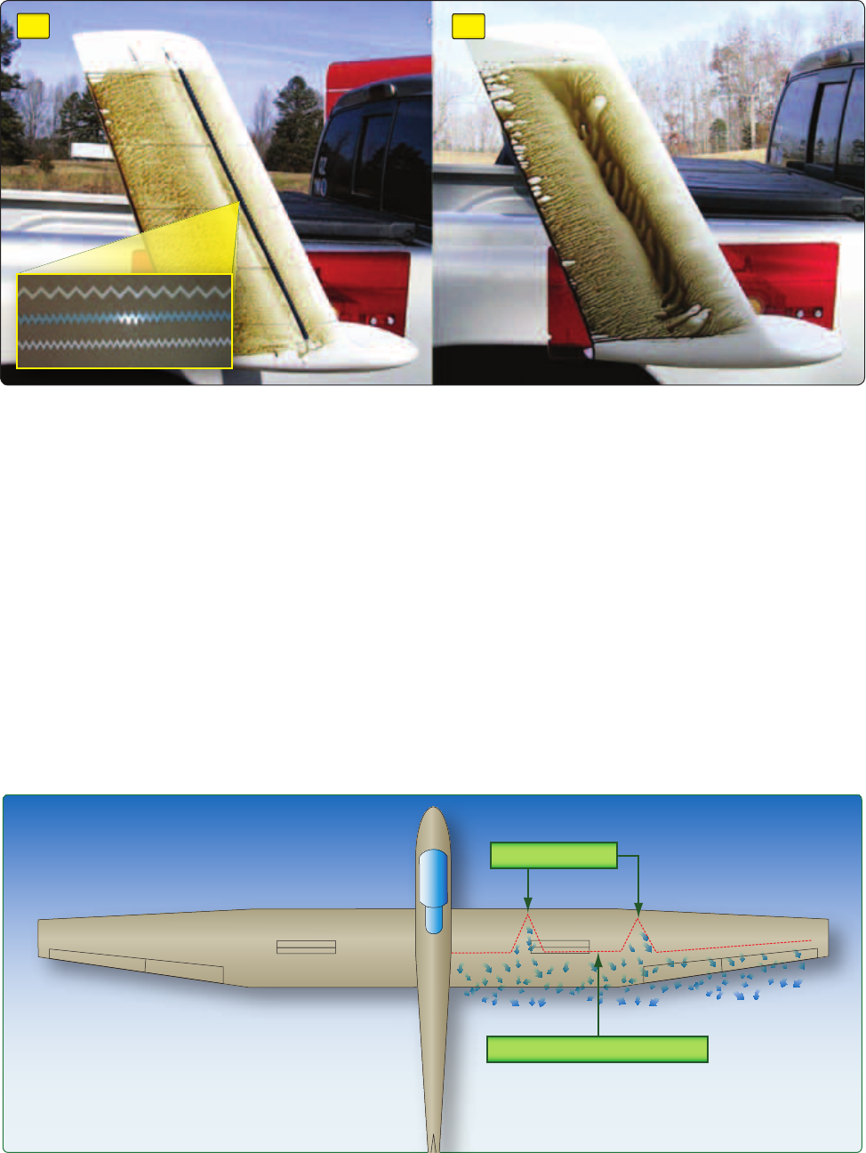
3-5
Figure 3-11. Turbulence due to insects, ice crystals, and dust.
Normal turbulent transition point
Splattered insects
Figure 3-10. Glider wing on the left shows the airflow with a turbulator installed and the glider wing on the right shows how the airflow
is disturbed without the turbulator installed.
A.
B.
The boundary layer can also be tripped into a turbulent ow
at any point by discontinuities on the wing’s surface. It is
important to keep wings clean and avoid rain and icing to
prevent premature transition, and the increase in drag that it
causes. As the boundary layer is only 1.0 millimeter thick at
the leading edge, objects, such as rivets, splattered insects,
rain drops, ice crystals, and dust, are all large enough to
cause localized turbulent transition to occur. [Figure 3-11]
Interference Drag
Interference drag occurs when varied currents of air over a
glider meet and interact. Placing two objects adjacent to one
another may produce turbulence 50–200 percent greater than
the parts tested separately. An example of interference drag
is the mixing of air over structures, such as the wing, tail
surfaces, and wing struts. Interference drag can be reduced
on gliders with fairings to streamline the intersection of air.
Induced Drag
Induced drag is generated as the wing is driven through the
air to develop the difference in air pressures that we call lift.
As the higher pressure air on the lower surface of the airfoil
curves around the end of the wing and lls in the lower
pressure area on the upper surface, the lift is lost, yet the
energy to produce the different pressures is still expended.
The result is drag because it is wasted energy. The more
energy the glider requires to y, the greater the required rate
of descent is to supply sufcient energy to convert into thrust

3-6
Figure 3-13. Total drag from the sum of parasite and induced drag.
Drag
Speed
I
n
d
u
c
e
d
d
r
a
g
P
a
r
a
s
i
t
e
d
r
a
g
T
o
t
a
l
d
r
a
g
(L/
D
MAX
)
Minimum
Drag
Figure 3-12. Induced drag is that part of total drag created by the production of lift, occurring only when lift is being developed.
Vertical lift
Total lift
Average relative wind
2
Wingtip vortices develop.
4
The average relative wind is inclined downward
and rearward, and lift is inclined aft. The rearward
component of lift is induced drag.
3
The downwash increases behind the wing.
1
High pressure air joins low pressure air at the
trailing edge of the wing and wingtips.
Low
pressure
Low
pressure
High pressure
High pressure
Atmospheric pressure
Atmospheric pressure
to overcome that unnecessary drag. The energy that produces
the vortices is wasted energy. The object of glider design is
to convert all of the energy into useful lift and the necessary
thrust. Any wasted energy translates into poorer performance.
[Figure 3-12] Glider designers attempt to reduce drag by
increasing the aspect ratio of the glider. The greater the aspect
ratio of the wing is, the lower the induced drag is. Wingtip
devices, or winglets, are also used to improve the efciency
of the glider. There are several types of wingtip devices and,
though they function in different manners, the intended effect
is always to reduce the aircraft’s drag by altering the airow
near the wingtips. Such devices increase the effective aspect
ratio of a wing, without materially increasing the wingspan.
Total Drag
Total drag on a glider is the sum of parasite and induced drag.
The total drag curve represents these combined forces and is
plotted against airspeed. [Figure 3-13]
L/D
MAX
is the point at which the lift-to-drag ratio is greatest. At
this speed, the total lift capacity of the glider, when compared
to the total drag of the glider, is most favorable. In calm air,
this is the airspeed used to obtain maximum glide distance.
Wing Planform
The shape, or planform, of the wings also has an effect on
the amount of lift and drag produced. The four most common
wing planforms used on gliders are elliptical, rectangular,
tapered, and swept forward. [Figure 3-14]
Elliptical Wing
An elliptical wing is a wing planform shape that minimizes
induced drag. Elliptical taper shortens the chord near the
wingtips in such a way that all parts of the wing experience
equivalent downwash, and lift at the wing tips is essentially

3-7
Figure 3-14. Planforms of glider wings.
Elliptical Wing Tapered Wing
Swept-Forward Wing
Rectangular Wing
zero, improving aerodynamic efciency. This wing design is
difcult and costly to manufacture because of the compound
curves in its design. The elliptical wing is more efcient in
terms of L
D
, but the wing’s uniform lift distribution causes
the entire span of the wing to stall simultaneously, potentially
causing loss of control with little warning.
Rectangular Wing
The rectangular wing is similar in efciency to the elliptical
wing, but is much easier to build. Rectangular wings have
very gentle stall characteristics with a warning buffet prior to
stall, and are easier to manufacture than elliptical wings. One
drawback to this wing design is that rectangular wings create
more induced drag than an elliptical wing of comparable size.
Tapered Wing
The tapered wing is the planform found most frequently
on gliders. Assuming equal wing area, the tapered wing
produces less drag than the rectangular wing, because there
is less area at the tip of the tapered wing. If speed is the
primary consideration, a tapered wing is more desirable than
a rectangular wing, but a tapered wing with no twist (also
called washout) has undesirable stall characteristics.
Swept-Forward Wing
A swept-forward planform is a wing conguration in which
the quarter-chord line of the wing has a forward sweep.
Swept-forward wings are used to allow the lifting area of
the wing to move forward, while keeping the mounting
point aft of the cockpit. This wing conguration is used on
some tandem two-seat gliders to allow for a small change in
center of gravity (CG) with the rear seat occupied, or while
ying solo. This type of planform design gives the glider
increased maneuverability due to airow from wing tip to
wing root, preventing a stall of the wing tips and ailerons at
high angles of attack. Instead, the stall occurs in the region
of the wing root.
Washout
Washout is built into wings by putting a slight twist between
the wing root and wing tip. When washout is designed into the
wing, the wing displays very good stall characteristics. Moving
outward along the span of the wing, the trailing edge moves
up in reference to the leading edge. This twist causes the wing
root to have a greater AOA than the tip, and as a result, stall
rst. This provides ample warning of the impending stall and,
at the same time, allows continued aileron control.

3-8
Figure 3-17. The glider polar graph helps determine the glider’s
best glide speed.
Airspeed (knots)
Sink rate (knots)
Best
lift/drag (L/D)
Tangent
Glider
sink rate
0 25 50 75
0
–1
–2
–3
–4
–5
–6
46 62
= :1
62
1.6
= 38:1
Best lift/drag (L/D)
ratio
–1.6
Figure 3-15. Glide polar graph.
Airspeed (knots)
Sink rate (knots)
0 25 50 75
0
–1
–2
–3
–4
–5
–6
Glide ratio at 75 knots = :1
75
3.4
= 22:1
Figure 3-16. Minimum sink speed can be found using the glide
polar graph.
Airspeed (knots)
Sink rate (knots)
Minimum sink
speed
0 25 50 75
0
–1
–2
–3
–4
–5
–6
46
= :1
46
1.3
= 35:1
Minimum sink
glide ratio
Glider sink rate
Minimum
flying speed
–1.3
Glide Ratio
Glide ratio is the number of feet a glider travels horizontally
in still air for every foot of altitude lost. If a glider has a 50:1
glide ratio, then it travels 50 feet for every foot of altitude lost.
Glide ratio =
Lift
: 1
Drag
This explains why minimizing drag is so critically important.
Because drag varies with airspeed, the glide ratio must also
vary with airspeed. A glide polar shown in Figure 3–15 is
a graph, normally provided in a glider’s ight manual, that
details the glider’s still air sink rate at airspeeds within its
ight envelope. The glide ratio at a particular airspeed can
be estimated from the glide polar using:
Glide ratio =
Airspeed
: 1
Sink rate
Airspeed and sink rate must both be in the same units. The
example in Figure 3-14 uses knots. The minimum sink speed
is the airspeed at which the glider loses altitude at the lowest
rate. It can be determined from the polar by locating the point
on the graph with the lowest sink rate and reading off the
corresponding airspeed. [Figure 3-16]
The best glide speed is the airspeed at which, in still air, the
glider achieves its best glide ratio. It is also known as the
best lift/drag (L/D) speed. This can be determined from the
polar by drawing a line from the origin that is tangential to
the curve (e.g., just touching). [Figure 3-17] The point of
contact is the best glide speed; the glide ratio at this speed
can be calculated as previously described. In still air, the
glider should be own at this speed to get from A to B with
minimum height loss.
Increasing the mass of a glider by adding water ballast,
for example, shifts the glide polar down and to the
right. [Figure 3-18] The minimum sink rate is therefore
increased, so as expected, the extra weight makes it harder
to climb in thermals. However, the best glide ratio remains
approximately the same, but now occurs at a higher airspeed.
Therefore, if the thermals are strong enough to compensate
for the poor climb performance, then water ballast allows a
faster inter-thermal cruise. This results in greater distances
being traveled per time interval.

3-9
Figure 3-18. Calculating glide speed with water ballast.
–1.9
Airspeed (knots)
Sink rate (knots)
Ballasted
lift/drag (L/D)
0 25 50 75
0
–1
–2
–3
–4
–5
–6
52 70
= :1
70
1.9
= 36:1
Ballasted
lift/drag (L/D)
Tangent
Glider
sink rate
Sink rate with
water ballast
Figure 3-19. Aspect ratio.
51' wing span
Wing area = 219.5 ft
2
Maximum gross weight = 1,040 lb
Aspect ratio = 11.85:1
Glide ratio = 22:1
Wing area = 193.32 ft
2
Maximum gross weight = 1,808 lb
Aspect ratio = 39:1
Glide ratio = 60:1
86' 11.3" wing span
Chord lines 4.3 feet
Chord lines 4.3 feet
Chord lines 2.22 feet Chord lines 2.22 feet
Aspect ratio is determined by dividing the wingspan (from wingtip to wingtip), by the average chord.
Aspect Ratio
The aspect ratio is another factor that affects the lift and drag
created by a wing. Aspect ratio is determined by dividing the
wingspan (from wingtip to wingtip), by the average wing chord.
Glider wings have a high aspect ratio, as shown in Figure 3-19.
High aspect ratio wings produce a comparably high amount of
lift at low angles of attack with less induced drag.
Weight
Weight is the third force that acts on a glider in ight. Weight
opposes lift and acts vertically through the CG of the glider.
Gravitational pull provides the force necessary to move a
glider through the air since a portion of the weight vector of
a glider is directed forward.
Thrust
Thrust is the forward force that propels a self-launching glider
through the air. Self-launching gliders have engine-driven
propellers that provide this thrust. Unpowered gliders have
an outside force, such as a towplane, winch, or automobile,
to launch the glider. Airborne gliders obtain thrust from
conversion of potential energy to kinetic energy.
Three Axes of Rotation
The glider is maneuvered around three axes of rotation: yaw
(vertical), lateral, and longitudinal. They rotate around one

3-10
Figure 3-20. Three axes of rotation.
Vertical axis
Longitudinal axis
Lateral axis
Y
A
W
P
I
T
C
H
R
O
L
L
CG
central point in the glider called the CG. This point is the
center of the glider’s total weight and varies with the loading
of the glider.
Yaw is movement around the vertical axis, which can be
represented by an imaginary straight line drawn vertically
through the CG. Moving the rudder left or right causes the
glider to yaw the nose to the left or right. Moving the ailerons
left or right to bank moves the glider around the longitudinal
axis. This axis would appear if a line were drawn through the
center of the fuselage from nose to tail. Pulling the stick back
or pushing it forward, raising or lowering the nose, controls
the pitch of the glider or its movement around the lateral axis.
The lateral axis could be seen if a line were drawn from one
side of the fuselage to the other through the CG. [Figure 3-20]
Stability
A glider is in equilibrium when all of its forces are in balance.
Stability is dened as the glider’s ability to maintain a
uniform ight condition and return to that condition after
being disturbed. Often during flight, gliders encounter
equilibrium-changing pitch disturbances. These can occur in
the form of vertical gusts, a sudden shift in CG, or deection
of the controls by the pilot. For example, a stable glider would
display a tendency to return to equilibrium after encountering
a force that causes the nose to pitch up.
Static stability and dynamic stability are two types of
stability a glider displays in ight. Static stability is the initial
tendency to return to a state of equilibrium when disturbed
from that state. The three types of static stability are positive,
negative, and neutral. When a glider demonstrates positive
static stability, it tends to return to equilibrium. A glider
demonstrating negative static stability displays a tendency
to increase its displacement. Gliders that demonstrate
neutral static stability have neither the tendency to return
to equilibrium nor the tendency to continue displacement.
Dynamic stability describes a glider’s motion and time
required for a response to static stability. In other words,
dynamic stability describes the manner in which a glider
oscillates when responding to static stability. A glider that
displays positive dynamic and static stability reduces its
oscillations with time. A glider demonstrating negative
dynamic stability is the opposite situation; its oscillations
increase in amplitude with time following a displacement.
A glider displaying neutral dynamic stability experiences
oscillations, which remain at the same amplitude without
increasing or decreasing over time. Figure 3-21 illustrates
the various types of dynamic stability.
Both static and dynamic stability are particularly important for
pitch control about the lateral axis. Measurement of stability
about this axis is known as longitudinal stability. Gliders are
designed to be slightly nose heavy in order to improve their
longitudinal stability. This causes the glider to tend to nose
down during normal ight. The horizontal stabilizer on the tail
is mounted at a slightly negative AOA to offset this tendency.
When a dynamically stable glider oscillates, the amplitude
of the oscillations should reduce through each cycle and
eventually settle down to a speed at which the downward force
on the tail exactly offsets the tendency to dive. [Figure 3-22]
Adjusting the trim assists in maintaining a desired
pitch attitude. A glider with positive static and dynamic
longitudinal stability tends to return to the trimmed pitch
attitude when the force that displaced it is removed. If a glider
displays negative stability, oscillations increase over time. If
uncorrected, negative stability can induce loads exceeding
the design limitations of the glider.

3-11
Figure 3-21. Three types of dynamic stability.
Neutral dynamic stability
Positive dynamic stability
Negative dynamic stability
Figure 3-22. Use of the horizontal stabilizer angle to offset the natural tendency of a glider to nose down.
Center of gravity
Center of lift
Negative AOA
(Exaggerated in
this illustration)
Another factor that is critical to the longitudinal stability of a
glider is its loading in relation to the CG. The CG of the glider
is the point at which the total force of gravity is considered
to act. When the glider is improperly loaded so it exceeds
the aft CG limit, it loses longitudinal stability. As airspeed
decreases, the nose of a glider rises. To recover, control inputs
must be applied to force the nose down to return to a level
ight attitude. It is possible that the glider could be loaded
so far aft of the approved limits that control inputs are not
sufcient to stop the nose from pitching up. If this were the
case, the glider could enter a spin from which recovery would
be impossible. Loading a glider with the CG too far forward
is also hazardous. In extreme cases, the glider may not have
enough pitch control to hold the nose up during an approach
to a landing. For these reasons, it is important to ensure that
the glider is within weight and balance limits prior to each
ight. Proper loading of a glider and the importance of CG
is discussed further in Chapter 5, Performance Limitations.
Flutter
Another factor that can affect the ability to control the glider
is utter. Flutter occurs when rapid vibrations are induced
through the control surfaces while the glider is traveling at
high speeds. Looseness in the control surfaces can result in
utter while ying near maximum speed. Another factor
that can reduce the airspeed at which utter can occur is a
disturbance to the balance of the control surfaces. If vibrations
are felt in the control surfaces, reduce the airspeed.

3-12
Figure 3-23. Lateral stability.
D
i
r
e
c
t
i
o
n
o
f
r
o
t
a
t
i
o
n
Angle of attack reduced, lift reduced
Angle of attack increased, lift increased
Lateral Stability
Another type of stability that describes the glider’s tendency
to return to wings-level ight following a displacement is
lateral stability. When a glider is rolled into a bank, it has a
tendency to sideslip in the direction of the bank. For example,
due to a gust of wind, the glider wing is lifted and the glider
starts to roll. The angle of attack on the downward going
wing is increased because the wing is moving down and
now the air is moving up past it. This causes the lift on this
wing to increase. On the upward going wing, the opposite is
occurring. The angle of attack is reduced because the wing
is moving up and the air is moving down past it. Lift on this
wing is therefore reduced. This does produce a countertorque
that damps out the rolling motion, but does not roll the glider
back to wings level as the effect stops when the glider stops.
[Figure 3-23] To obtain lateral stability, dihedral is designed
into the wings.
Dihedral is the upward angle of the wings from a horizontal
(front/rear view) axis of the plane. As a glider ies along

3-13
Figure 3-25. Forces in a banked turn.
Vertical component
of lift (effective lift)
Weight
Resultant force
Centrifugal force
Lift
Figure 3-26. Centripetal force is a force that makes a body follow
a curved path.
Centripetal force
Figure 3-24. Dihedral angle.
Dihedral angle Dihedral angle
and encounters turbulence, the dihedral provides positive
lateral stability by providing more lift for the lower wing
and reducing the lift on the raised wing. As one wing lowers,
it becomes closer to perpendicular to the surface and level.
Because it is closer to level and perpendicular to the weight
force, the lift produced directly opposes the force of weight.
This must be instantly compared to the higher and now
more canted wing referenced to the force of weight. The
higher wing’s lift relative to the force of weight is now less
because of the vector angle. This imbalance of lift causes the
lower wing to rise as the higher descends until lift equalizes,
resulting in level ight. [Figure 3-24]
Turning Flight
Before a glider turns, it must rst overcome inertia, or its
tendency to continue in a straight line. A pilot creates the
necessary turning force by using the ailerons to bank the
glider so that the direction of total lift is inclined. This divides
the force of lift into two components; one component acts
vertically to oppose weight, while the other acts horizontally
to oppose centrifugal force. The latter is the horizontal
component of lift. [Figure 3-25]
To maintain attitude with the horizon during a turn, glider
pilots need to increase back pressure on the control stick. The
horizontal component of lift creates a force directed inward
toward the center of rotation, which is known as centripetal
force. [Figure 3-26] This center-seeking force causes the glider
to turn. Since centripetal force works against the tendency of
the aircraft to continue in a straight line, inertia tends to oppose
centripetal force toward the outside of the turn. This opposing
force is known as centrifugal force. In reality, centrifugal force
is not a true aerodynamic force; it is an apparent force that
results from the effect of inertia during the turn.
Load Factors
The preceding sections only briey considered some of the
practical points of the principles of turning ight. However,
with the responsibilities of the pilot and the safety of
passengers, the competent pilot must have a well-founded
concept of the forces that act on the glider during turning
ight and the advantageous use of these forces, as well as
the operating limitations of the particular glider. Any force
applied to a glider to deect its ight from a straight line
produces a stress on its structure; the amount of this force is
called load factor.

3-14
Figure 3-28. The loads placed on a glider increase as the angle of
bank increases.
9
8
7
6
5
4
3
2
1
0
Load factor (Gs)
Angle of bank (degrees)
0° 10° 20° 30° 40° 50° 60° 70° 80° 90° 100°
Figure 3-27. A glider’s stall speed increases as the bank angle
increases. For example, a 60° angle of bank causes a 40 percent
increase in the glider’s stall speed.
180
160
140
120
100
80
60
40
20
0
Percentage increase in stall speed
Angle of bank (degrees)
0° 10° 20° 30° 40° 50° 60° 70° 80° 90° 100°
A load factor is the ratio of the total air load acting on the
glider to the gross weight of the glider. A glider in ight with
a load factor of one does not mean the glider is accelerating;
it means the lift on the aircraft is the same as in straight-
and-level ight. Load factor may be positive or negative,
dependent on the current ightpath.
A load factor of three means that the total load on a glider’s
structure is three times its gross weight. Gravity load factors
are usually expressed in terms of “G”—that is, a load factor
of three may be spoken of as three Gs, or a load factor of
four as four Gs. A load factor of one, or 1 G, represents
conditions in straight-and-level ight, in which the lift is
equal to the weight. Therefore, two Gs would be two times
the normal weight. Gliders may be designed to withstand
stress of up to nine Gs.
It is interesting to note that in subjecting a glider to three Gs
in a pullup from a dive, the pilot is pressed down into the
seat with a force equal to three times the person’s weight.
Thus, an idea of the magnitude of the load factor obtained in
any maneuver can be determined by considering the degree
to which the pilot is pressed down into the seat. Since the
operating speed of modern gliders has increased signicantly,
this effect has become so pronounced that it is a primary
consideration in the design of the structure for all gliders.
If attempting to improve turn performance by increasing
angle of bank while maintaining airspeed, pay close attention
to glider limitations due to the effects of increasing the load
factor. Load factor is dened as the ratio of the load supported
by the glider’s wings to the actual weight of the aircraft and
its contents. A glider in stabilized, wings-level ight has a
load factor of one. Load factor increases rapidly as the angle
of bank increases due to increase wing loading. [Figure 3-27]
With the structural design of gliders planned to withstand
only a certain amount of overload, knowledge of load factors
has become essential for all pilots. Load factors are important
to the pilot for two distinct reasons:
1. It is possible for a pilot to impose an obviously
dangerous overload on the glider structures.
2. Increased load factor increases the stalling speed,
making stalls possible at seemingly safe ight speeds
due to increased wing loading.
In a turn at constant speed, the AOA must be increased to
furnish the extra lift necessary to overcome the centrifugal
force and inertia opposing the turn. As the bank angle
increases, AOA must also increase to provide the required lift.
The result of increasing the AOA is a stall when the critical
AOA is exceeded in a turn. [Figure 3-28]
Rate of Turn
Rate of turn refers to the amount of time it takes for a glider
to turn a specied number of degrees. If own at the same
airspeed and angle of bank, every glider turns at the same
rate. If airspeed increases and the angle of bank remains
the same, the rate of turn decreases. Conversely, a constant
airspeed coupled with an angle of bank increase results in a
higher rate of turn.
Radius of Turn
The amount of horizontal distance an aircraft uses to complete
a turn is referred to as the radius of turn. The radius of turn
at any given bank angle varies directly with the square of the
airspeed. Therefore, if the airspeed of the glider were doubled,

3-15
Figure 3-29. A glider’s radius of turn as compared to angle of bank.
30°
45°
60°
TAS 40 MPH
TAS 60 MPH
TAS 80 MPH
feetTurn radius
701
feetTurn radius
042
feetTurn radius
824
feetTurn radius
581
feetTurn radius
714
feetTurn radius
047
feetTurn radius
260
feetTurn radius
931
feetTurn radius
742
Level stall airspeed at gross weight is 38 knots
Stall speed: 41 knots
Stall speed: 45 knots Stall speed: 53 knots
the radius of the turn would be four times greater. Although
the radius of turn is also dependent on a glider’s airspeed and
angle of bank, the relationship is the opposite of rate of turn.
As the glider’s airspeed is increased with the angle of bank
held constant, the radius of turn increases. On the other hand,
if the angle of bank increases and the airspeed remains the
same, the radius of turn is decreased. [Figure 3-29] When
ying in thermals, the radius of turn is an important factor as
it helps to gain the maximum altitude. A smaller turn radius
enables a glider to y closer to the fastest rising core of the
thermal and gain altitude more quickly.
Turn Coordination
It is important that rudder and aileron inputs are coordinated
during a turn so maximum glider performance can be
maintained. If too little rudder is applied, or if rudder is
applied too late, the result is a slip. Too much rudder, or
rudder applied before aileron, results in a skid. Both skids
and slips swing the fuselage of the glider into the relative
wind, creating additional parasite drag, which reduces lift
and airspeed. Although this increased drag caused by a slip
can be useful during approach to landing to steepen the
approach path and counteract a crosswind, it decreases glider
performance during other phases of ight.
When rolling into a turn, the aileron on the inside of the
turn is raised and the aileron on the outside of the turn is
lowered. The lowered aileron on the outside wing increases
lift by increasing wing camber and produces more lift for that
wing. Since induced drag is a byproduct of lift, the outside
wing also produces more drag than the inside wing. This
causes adverse yaw, a yawing tendency toward the outside
of the turn. Coordinated use of rudder and aileron corrects
for adverse yaw and aileron drag. Adverse yaw in gliders
can be more pronounced due to the much longer wings as
compared to an airplane of equal weight. The longer wings
constitute longer lever arms for the adverse yaw forces to act
on the glider. Therefore, more rudder movement is necessary
to counteract the adverse yaw and have a coordinated turn.
Slips
A slip is a descent with one wing lowered and the glider’s
longitudinal axis at an angle to the ightpath. It may be used
for one or both of two purposes: to steepen the approach path
without increasing the airspeed, as would be the case if a dive
were used, or used to make the glider move sideways through
the air to counteract the drift that results from a crosswind.
Formerly, slips were used as a normal means of controlling
landing descents to short or obstructed elds, but they are
now primarily used in the performance of crosswind and
short-eld landings. With the installation of wing aps
and effective spoilers on modern gliders, the use of slips to
steepen or control the angle of descent is no longer the only
procedure available. However, pilots still need skill in the
performance of forward slips to correct for possible errors
in judgment of the landing approach.
The shape of the glider’s wing planform can greatly affect
the slip. If the glider has a rectangular wing planform, the slip
has little effect on the lift production of the wing other than
the wing area being obscured by the fuselage vortices. The
direction of the relative wind to the wing has the same effect
on both wings so no inequalities of lift form. However, if the
wing is tapered or has leading edge aft sweep, then the relative
wind has a large effect on the production of lift.

3-16
Figure 3-30. A comparison of a forward slip to a sideslip.
Forward Slip Slideslip
If a glider with tapered wings, as shown in Figure 3-14, were
to begin a slip to the left with the left wing lower, the left
wing will have a relative wind more aligned with its chord
line and effectively higher airow (airspeed) that generates
more lift as compared to the higher right wing with angled
relative wind, resulting in lower effective airow (airspeed)
over that wing. This differential in airow or relative airspeed
of the wings when taken to the extremes of the ight envelope
results in the higher wing stalling and often an inverted spin.
Depending on the exact wing shape, an elliptical wing can
have characteristics more like a tapered wing. [Figure 3-14]
Pilots should always consult the GFM and know what the
gliders limitations are concerning slips.
The use of slips has limitations. Some pilots may try to
lose altitude by violent slipping, rather than by smoothly
maneuvering, exercising good judgment, and using only a
slight or moderate slip. In short-eld landings, this erratic
practice invariably leads to trouble since enough excess speed
may prevent touching down anywhere near the proper point,
and very often results in overshooting the entire eld.
If a slip is used during the last portion of a nal approach,
the longitudinal axis of the glider must be aligned with the
runway just prior to touchdown so that the glider touches
down headed in the direction in which it is moving over
the runway. This requires timely action to modify the slip
and align the glider’s longitudinal axis with its direction of
travel over the ground at the instant of touchdown. Failure
to accomplish this imposes severe sideloads on the landing
gear and imparts violent ground looping tendencies.
Discontinuing the slip is accomplished by leveling the wings
and simultaneously releasing the rudder pressure, while
readjusting the pitch attitude to the normal glide attitude. If
the pressure on the rudder is released abruptly, the nose swings
too quickly into line and the glider tends to acquire excess speed.
Because of the location of the pitot tube and static vents,
airspeed indicators in some gliders may have considerable
error when the glider is in a slip. The pilot must be aware of
this possibility and recognize a properly performed slip by
the attitude of the glider, the sound of the airow, and the
feel of the ight controls.
Forward Slip
The forward slip is a slip in which the glider’s direction of
motion is the same as before the slip was begun. [Figure 3-30]
The primary purpose of a forward slip is to dissipate altitude
without increasing the glider’s speed, particularly in gliders
not equipped with aps, or if the spoilers are inoperative.
There are many circumstances requiring the use of forward
slips, such as a landing approach over obstacles and short-
eld landings, in which it is always wise to allow an extra
margin of altitude for safety in the original estimate of the
approach. In the latter case, if the inaccuracy of the approach
is conrmed by excess altitude when nearing the boundary of
the selected eld, slipping can dissipate the excess altitude.
If there is any crosswind, the slip is much more effective if
made toward the wind.
Assuming the glider is originally in straight ight, the wing
on the side toward which the slip is to be made should be
lowered by use of the ailerons. Simultaneously, the airplane’s
nose must be yawed in the opposite direction by applying
opposite rudder so that the glider’s longitudinal axis is at an
angle to its original ightpath. The degree to which the nose
is yawed in the opposite direction from the bank should be
such that the original ground track is maintained. The nose
should also be raised as necessary to prevent the airspeed
from increasing.

3-17
Figure 3-31. A stall occurs when the critical angle of attack is exceeded.
Separation starts Separation moves forward Airfoil stalls
Note: Forward slips with wing aps extended should not
be done in gliders wherein the manufacturer’s operating
instructions prohibit such operation.
Sideslip
A sideslip, as distinguished from a forward slip, is one during
which the glider’s longitudinal axis remains parallel to the
original ightpath, but in which the ightpath changes direction
according to the steepness of the bank. To perform a sideslip,
the upwind wing is lowered, and simultaneously the opposite
rudder is applied to maintain the landing area alignment.
The sideslip is important in counteracting wind drift during
crosswind landings and is discussed in a later chapter.
The dihedral angle of the wings works to add lateral stability
to the airframe and ease the pilot’s tasking to correct for
upsets. As the glider ies along, turbulence may upset the
balance and raise one wing and roll the glider about the
longitudinal axis. As the wing rises, the vertical lift vector
decreases while the horizontal component of the wing’s
lifting force increases. As the other wing descends, the lifting
force vertical component increases while the horizontal
component decreases. This imbalance is designed so the
airframe returns to level without pilot input. Depending on the
airows, the AOA on the wings may or may not be a factor.
If the air on one wing is descending (sink) and the air on the
other wing is ascending (lift) both wings will have different
relative winds, thus different AOAs and developed lift.
Stalls
It is important to remember that a stall can occur at any airspeed
and at any ight attitude. A stall occurs when the critical AOA
is exceeded. [Figure 3-31] During a stall, the wings still
support some of the aircraft’s weight. If the wings did not, it
would accelerate according to Newton’s Second Law. The stall
speed of a glider can be affected by many factors, including
weight, load factor due to maneuvering, and environmental
conditions. As the weight of the glider increases, a higher AOA
is required to maintain ight at the same airspeed since more
lift is required to support the increase in weight. This is why
a heavily loaded glider stalls at a higher airspeed than when
lightly loaded. The manner in which this weight is distributed
also affects stall speed. For example, a forward CG creates a
situation that requires the tail to produce a greater downforce to
balance the aircraft. The result of this conguration requires the
wings to produce more lift than if the CG were located further
aft. Therefore, a more forward CG also increases stall speed.
Environmental factors also can affect stall speed. Snow, ice,
or frost accumulation on the wing’s surface can increase the
weight of the wing, in addition to changing the wing shape
and disrupting the airow, all of which increase stall speed.
Turbulence is another environmental factor that can affect a
glider’s stall speed. The unpredictable nature of turbulence
can cause a glider to stall suddenly and abruptly at a higher
airspeed than it would in stable conditions. Turbulence has a
strong impact on the stall speed of a glider because the vertical
gusts change the direction of the relative wind and abruptly
increase the AOA. During landing in gusty conditions, it is
important to increase the approach airspeed by half of the
gust spread value in order to maintain a wide margin above
stall. For example, if the winds were 10 knots gusting to 15
knots, it would be prudent to add 2.5 knots ((15 – 10) ÷ 2
= 2.5) to the approach speed. This practice usually ensures
a safe margin to guard against stalls at very low altitudes.
Spins
If the aircraft is not stalled, it cannot spin. A spin can be
defined as an aggravated stall that results in the glider
descending in a helical, or corkscrew, path. A spin is a
complex, uncoordinated ight maneuver in which the wings
are unequally stalled. Upon entering a spin, the wing that
is more completely stalled drops before the other, and the
nose of the aircraft yaws in the direction of the low wing.
[Figure 3-32]

3-18
Figure 3-32. The relative coefficients of lift and drag for each wing
during a spin. Note that the ascending wing experiences more lift
and less drag. The opposite wing is forced down and back due to
less lift and increased drag.
Increasing C
L
and C
D
Coefficient of lift (C
L
)
C
o
e
f
f
i
c
i
e
n
t
o
f
d
r
a
g
(
C
D
)
Descending wing
Stall
Ascending wing
Increasing AOA
Figure 3-33. A glider’s stall speed increases as the bank angle increases. In a spin, one wing is more deeply stalled than the other.
Erect spin Inverted spin Flat spin
The cause of a spin is stalled airow over one wing before
airflow stalling over the other wing. This is a result of
uncoordinated ight with unequal airows over the wings.
Spins occur in uncoordinated slow ight and high rate turns
(overbanking for airspeed). The lack of coordination is
normally caused by too much or not enough rudder control
for the amount of aileron being used. If the stall recovery is
not promptly initiated, the glider is likely to enter a full stall
that may develop into a spin. Spins that occur as the result
of uncoordinated ight usually rotate in the direction of the
rudder being applied, regardless of the raised wing. When
entering a slipping turn, holding opposite aileron and rudder,
the resultant spin usually occurs in the direction opposite of
the aileron already applied. In a skidding turn in which both
aileron and rudder are applied in the same direction, rotation is
also in the direction of rudder application. Glider pilots should
always be aware of the type of wing forms on their aircraft
and the stall characteristics of that wing in various maneuvers.
Spins are normally placed in three categories, as shown
in Figure 3-33. The most common is the upright, or erect,
spin, which is characterized by a slightly nose-down rolling
and yawing motion in the same direction. An inverted spin
involves the aircraft spinning upside down with the yaw and
roll occurring in opposite directions. A third type of spin, the
3-19
at spin, is the most hazardous of all spins. In a at spin, the
glider yaws around the vertical axis at a pitch attitude nearly
level with the horizon. A at spin often has a very high rate of
rotation; the recovery is difcult, and sometimes impossible.
If a glider is properly loaded within its CG limits, entry into a
at spin should not occur. Erect spins and at spins can also
be inverted. The entry, wing form, and CG usually determine
the type of spin resulting from an uncoordinated wing stall.
Since spins normally occur when a glider is own in an
uncoordinated manner at lower airspeeds, coordinated use of
the ight controls is important. It is critical that pilots learn
to recognize and recover from the rst sign of a stall or spin.
Entering a spin near the ground, especially during the landing
pattern, is usually fatal. [Figure 3-33] A pilot must learn to
recognize the warning signs, especially during the approach
and landing phase in a crosswind. A crosswind resulting in
a tailwind on the base leg may lead the pilot to tighten the
turn using rudder, or too steep a turn for the airspeed. An
uncoordinated turn could lead to the upper wing exceeding
its critical AOA before the lower wing, which could result
in a very high rate of roll towards the upper wing as the
upper wing stalls. If an excessive steep turn is attempted, the
glider may roll towards the inside wing or the outside wing
depending on the exact trim state at the instant of the stall.
Situational awareness of position to nal approach should
be part of a before-landing routine.
Ground Effect
Ground effect is a reduction in induced drag for the same
amount of lift produced. Within one wingspan above the
ground, the decrease in induced drag enables the glider to y
at a lower airspeed. In ground effect, a lower AOA is required
to produce the same amount of lift. Ground effect enables the
glider to y near the ground at a lower airspeed and causes
the glider to oat as it approaches the touchdown point.
During takeoff and landing, the ground alters the three-
dimensional airow pattern around the glider. The result is
a decrease in downwash and a reduction in wingtip vortices.
Upwash and downwash refer to the effect an airfoil has on
the free airstream. Upwash is the deection of the oncoming
airstream upward and over the wing. Downwash is the
downward deection of the airstream as it passes over the
wing and past the trailing edge.
During ight, the downwash of the airstream causes the
relative wind to be inclined downward in the vicinity of the
wing. This is called the average relative wind. The angle
between the free airstream relative wind and the average
relative wind is the induced AOA. In effect, the greater the
downward deection of the airstream, the higher the induced
AOA and the higher the induced drag. Ground effect restricts
the downward deection of the airstream, decreasing both
induced AOA and induced drag.
Ground effect, in addition to the decrease in wind due to
surface friction and other terrain features upwind of the
landing area, can greater increase the landing distance of
a glider. A glider pilot, especially a visiting pilot, should
inquire about local effects from local pilots to enhance ight
planning and safe landings.
3-20
