HSM Jet Spindle
User Manual
Typhoo
n
H S M Jet S p i n d l e s

|
3
||
2
|
General
General
HSM Jet Spindle HSM Jet Spindle
FCC Compliance Statement
This device has been tested and found to comply with the limits for
a Class A digital device, pursuant to Part 15 of the FCC Rules. These
limits are designed to provide reasonable protection against harmful
interference in residential installations. This equipment generates uses
and can radiate radio frequency energy and, if not installed and used in
accordance with the instructions, may cause harmful interference to
radio and television reception.
However, there is no guarantee that interference will not occur in a
particular installation. If this device does cause such interference, which
can be veried by turning the device off and on, the user is encouraged
to eliminate the interference by one or more of the following measures:
• Re-orient or re-locate the receiving antenna.
• Increase the distance between the device and the receiver.
• Connect the device to an outlet on a circuit different from the one
that supplies power to the receiver.
• Consult the dealer or an experienced radio/TV technician.
!
WARNING! Changes or modications to this unit not expressly
approved by the party responsible for compliance could void
the user’s authority to operate the equipment.
This device complies with FCC Rules Part 15:
Operation is subject to two conditions:
1. This device may not cause harmful interference, and
2. This device must accept any interference that may
be received or that may cause undesired operation.
To comply with FCC Section 1.310 for human
exposure to radio frequency electromagnetic
elds, implement the following instruction:
A distance of at least 20 cm between
the equipment and all persons should be
maintained during the operation
of the equipment.
Table of Contents
1. General / FCC Compliance Statement ...................................... 3
1.1 Safety First ............................................................................................................4
1.2 Statement of Conformity ................................................................................5
1.2.1 European Standards (CE) ..................................................................................5
1.2.2 American Standards (UL) .................................................................................. 5
1.2.3 International Standards ....................................................................................5
1.3 Introduction ..........................................................................................................6
1.4 Case Contents ......................................................................................................6
1.5 Main Features .......................................................................................................7
1.5.1 Wireless Rotation Speed Display - Overview ............................................7
1.5.2 Built-in and Direct Mounting System to CNC Spindle .............................9
1.5.3 Shaft Locking for Tool Clamping ....................................................................9
1.5.4 Integrated Coolant Nozzle System ...........................................................10
1.5.5 Tool Clamping .....................................................................................................10
2. Installation ................................................................................. 11
2.1 Battery Installation for RPM Wireless Transmitter ................................ 11
2.2 Display ....................................................................................................................11
2.2.1 Prerequisite for Display Installation ............................................................11
2.2.2 Display Installation Workspace ..................................................................... 11
2.2.3 Connect HSM Jet Spindle to Display ........................................................... 12
2.2.4 Display Screens .................................................................................................. 13
2.2.5 Disconnect HSM Jet Spindle from Display ................................................. 17
2.3 HSM Jet Spindle ..................................................................................................18
2.3.1 Prerequisite for CNC Machine ........................................................................ 18
2.3.2 HSM Jet Spindle Installation to CNC Machine ...........................................18
2.3.3 Placement of HSM Jet Spindle in Toolholder............................................19
2.3.4 Tool Prerequisites ............................................................................................20
2.3.5 Tool Installation for HSM Jet Spindle .......................................................... 21
2.3.6 Tool Clamping and Runout Check (Recommendations) .................... 23
3. Maintenance .............................................................................. 24
3.1 Periodic Maintenance ...................................................................................... 24
3.2 Battery Change on RPM Transmitter......................................................... 24
3.3 Recommended Operating Environment .................................................. 24
3.4 Storage ................................................................................................................ 24
3.4.1 Pre-Storage ........................................................................................................ 24
3.4.2 Storage Conditions .......................................................................................... 24
4. Working with the HSM Jet Spindle .......................................... 25
4.1 Recalculation of Table Feed for HSM Jet Spindle ................................... 25
4.1.1 Existing Machining Process ........................................................................... 26
4.1.2 New Machining Process .................................................................................. 26
5. Troubleshooting ........................................................................ 27
5.1 Display Messages ..............................................................................................27
5.2 HSM JET Spindle Shaft Does Not Rotate (cont’d) ..................................27
5.3 HSM Jet Spindle Not Used Within the Past Month .................................27
6. Warranty Summary ...................................................................28
7. Customer Service after Purchase .............................................31

|
5
||
4
|
General
General
HSM Jet Spindle HSM Jet Spindle
1. General
1.1 Safety First
!
Read the Manual
Safety of the operator is a main concern. This equipment is as
safe as we are able to make it. Avoid accidents by reading the
safety alerts, investing a few seconds of thought and a careful
approach to handling equipment. You, the operator, can avoid
many accidents by observing the following precautions. Review
the safety instructions of the manufacturer, suppler, owner, and
all organizations responsible for the prevention of accidents.
!
Ensure the Following:
The work area and the area around the CNC machine are free
of obstacles The work area is properly lit
This equipment is operated only by a responsible adult trained in
this operation This equipment is not operated by a person under
the inuence of drugs or alcohol This equipment is not operated
by a person with any illness or physical condition that might
reduce reexes or awareness and increase exposure to risk.
Before starting any kind of work, install all of the safety devices
prescribed by the builder of the machine or power tool
!
Warning: Rotating Tools, Entanglement Hazard
To avoid risks associated with the use of rotating tools it
is strongly recommended to use the utmost caution and
concentration when working.
!
Warning: Rotating Tools, Cut or Severe Hazard
Always wear correctly sized gloves that allow the sensitivity
necessary to operate the tool correctly and give adequate
protection in the event of the blade being touched during use.
!
Warning:
Always use safety glasses or protective screens to protect
your eyes.
!
Only install tools in perfect condition that are recommended
for the material to be worked and that are suitable for the
type of machine used.
Do not use cracked or deformed tools.
Check that the balancing, keying and centering of rotary tools
are carried out correctly
Secure the tool correctly using the proper tightening and
adjustment devices. Remove all tightening and adjustment
devices before use.
Check that the tool rotates in the correct direction.
Never exceed the limits of a piece of machinery. If its ability
to do a job or to do so safely is in question - DON’T TRY IT.
1.2 Statement of Conformity
The HSM Jet Spindle meets the following standards:
1.2.1 European Standards (CE)
• EMC: EN 301489-1/17
• Radio: EN 300328 V 1.8.1
• Safety: EN 61010-1:2010
1.2.2 American Standards (UL)
• EMC: FCC Part 15 B
• Radio: FCC Part 15 C
• Safety: UL 61010-1
1.2.3 International Standards
• Safety: IEC 61010-1:2010

|
7
||
6
|
General
General
HSM Jet Spindle HSM Jet Spindle
1.3 Introduction
The HSM Jet Spindle is a unique High Speed Machining (HSM), spindle
(20K RPM Yellow, 30K RPM Red, 40K RPM Blue). It is driven by the CNC
machine spindle’s coolant-through-ow, at a minimum pressure of 20 bar.
The HSM Jet Spindle does not require any special installation, aside from
mounting onto the machine spindle. It operates as any other standard
toolholder in the tool magazine or ATC.
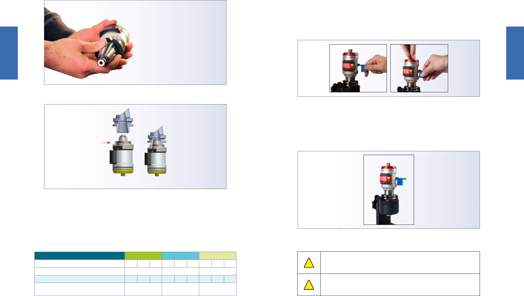
1.4 Case Contents
The HSM Jet Spindle
case includes:
The wireless RPM display
case includes:
Fig. 1. Spindle case contents Fig. 2. Display case contents
1. Nut ER11 GHS
2. Wrench ER11 SMS
3. Shaft Lock Flag Key
4. Allen key - Hexagonal 2.0 mm
5. Battery - Lithium metal
non-rechargeable, CR2 type
1. TSD - wireless RPM display
2. AC/DC 5V power supply
* Actual size and types of accessories
may vary due to conguration and
manufacturing process
* For USA/Japan: Include EU to US/Japan AC
adapter plug
1.5 Main Features
The HSM Jet Spindle system uses the machine’s existing coolant or cutting
uid supply as a pressurized energy source (20 to 40 bars), rotating a
turbine in the range of about 50,000 RPMs.
It offers an ideal solution for a wide range of semi-nishing and nishing
applications such as milling, drilling, thread-milling, engraving, chamfering,
deburring, ne radial grinding and more. The Jet Spindle is equipped with
real-time wireless RPM transmitting and monitoring; to optimize cutting
conditions.
Fig. 3. Shaft lock ag key and wench
Fig. 4. Spindle selection
Fig. 5. HSM Jet Spindle wireless transmitter and display
HSM Jet Spindle type TJS 20K... TJS 30K... TJS 40K...
Operating range of coolant pressure [bar]
20
-
40 20
-
40 20
-
40
Operating range of coolant ow rate [l/min]
12-18 12-18 12-18
Rotational spindle speed [Krpm]*
30
-
45 35
-
55
40
-
60
Optimum cutting tool diameter [mm]
Drilling 0.5-2.0,
Milling 1.0-3.5
Drilling 0.5-2.0,
Milling 1.5-3.5
Drilling 0.5-1.0,
Milling 0.5-1.2
* Notes:
• Rotational spindle speed is based on coolant pressure and flow rate.
• Coolant pressure is measured from the spindle inlet.
1.5.1 Wireless Rotation Speed Display - Overview
The HSM Jet Spindle is equipped with an integrated wireless display system,
allowing real-time monitoring of the rotation speed during machining.
The spindle housing is tted with a wireless transmitter that sends RPM
data to the display unit (receiver) mounted outside of the machine.
The receiver is powered by a 5V DC universal AC/DC power adapter
connected to either a 220V AC or 110V AC power source.
The transmitter is powered by a non-rechargeable CR2 lithium battery.

|
9
||
8
|
General
General
HSM Jet Spindle HSM Jet Spindle
Display Information
Fig. 6. Wireless RPM display main view
Fig. 8. HSM Jet Spindle with mounting adaptation options (for Illustration purposes only)
Fig. 7. Wireless RPM display mounting options
Fig. 9. HSM Jet Spindle with shaft lock mechanism
1.5.2 Built-in and Direct Mounting System to CNC Spindle
The HSM Jet Spindle is available with several mounting adaptation options:
• ER32 collet chuck with a special tightening nut, suitable for all standard
toolholders with an ER32 adaptation.
• Integral options for various other adaptations are available upon
request.
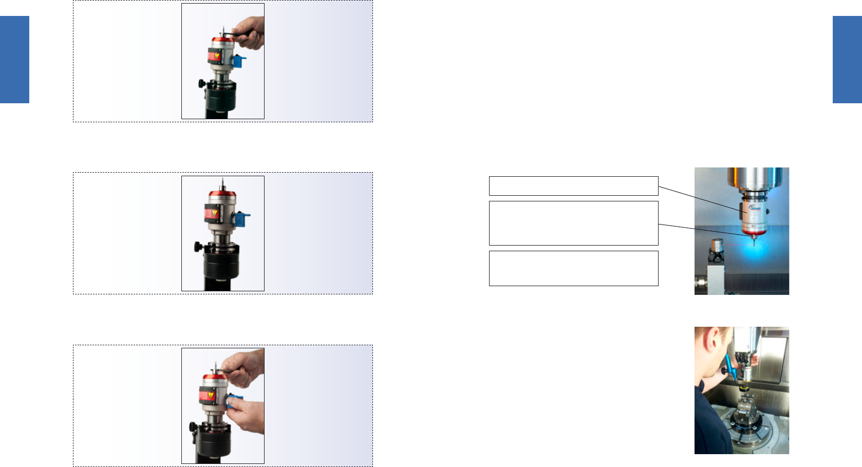
1.5.3 Shaft Locking for Tool Clamping
The shaft lock mechanism provides a simple, easy way to change the
cutting tool on the HSM Jet Spindle. For tool mounting instructions, see
page 21.
!
Warning:
Do not hold the Flag Key while tightening/loosening the shaft lock
mechanism. Key may break off in the shaft lock causing damage.
!
Shaft lock protection plug must be in place at all times during spindle
operation. It is strictly prohibited to operate the HSM Jet spindle if the
shaft lock protection plug is damaged or missing.
• 2.4 GHz radio frequency transmission
• Direct wireless rotational speed monitoring, range up to 10m
• Externally powered receiver display
• Connection up to 127 tools. Displays information from only one
operating unit
• Internal battery-powered transmitter unit
• Individual ID number for each transmitter unit
Spindle RPM LCD screen
Transmitter
unit’s Battery
level
Function buttons
Transmitter unit
identification
number
Signal readout
Power
switch on/off
DC power
socket
RPM wireless
transmitter
detection side
Unit ID
number
PRM transmitter
unit
Receiver display dimensions
StandDC power
socket
Attach to the machine
panel by built-in magnets

|
11
|
Installation
HSM Jet Spindle
|
10
|
General
HSM Jet Spindle
1.5.4 Integrated Coolant Nozzle System
Integrated coolant nozzle system provides direct jet coolant application
for fast efcient chip evacuation.
1.5.5 Tool Clamping
The HSM Jet Spindle is compatible with ER11 collet chuck. It is recommended
to use ER 11 high-precision spring collets.
When longer overhang is required, 10 and 25mm length ER11 thermal
shrink collets are available.
Fig. 10. Integrated coolant nozzle system
Fig. 12. Battery case opening
Fig. 11. Overhang solution types
NUT ER11 GHS
Collet ER11 SPR
NUT ER11 GHS
+10 mm
+15 mm
NUT ER11 GHS
ER11 SRK ...25
Thermal collet
ER11 SRK ...10
Thermal collet
2. Installation
2.1 Battery Installation for RPM Wireless Transmitter
Install battery into the RPM transmitter:
1. Unscrew the 4 battery case cover screws using a hexagonal 2 mm
Allen key.
2. Remove the case cover.
3. Make sure the O-ring inside the cover
is seated well, and is intact.
4. Insert the CR2 lithium battery in the
correct direction.
5. Replace the battery case cover.
6. Replace the 4 screws to secure the
battery case cover.
7. The transmitter is ready for operation.
2.2 Display
HSM Jet Spindle is equipped with an integrated wireless display unit,
allowing real-time monitoring of the rotating speed during machining.
2.2.1 Prerequisite for Display Installation
Make sure that the following prerequisites are met:
1. Electrical power: 220/110V AC, standard socket.
2. Distance from HSM Jet Spindle to display unit: no more than 10 m.
3. Create space for the display unit to provide close-up and
unobstructed viewing.
2.2.2 Display Installation Workspace
1. Mount the display onto a metallic surface using the magnet on the
back of the display, or place on a at and level surface.
2. Connect the display to an AC socket.
3. Switch the display ON.
ON
RPM wireless transmitter
detection side
Fig. 13. Switch display ON

|
13
||
12
|
Installation
Installation
HSM Jet Spindle HSM Jet Spindle
2.2.3 Connect HSM Jet Spindle to Display
The display and the HSM Jet Spindle must be connected (paired) so they
can “identify” each other. Each transmitter unit has an individual ID number
(See images below) How to connect the HSM Jet Spindle to the display:
1. Make sure the display is ON.
2.
Press ‘CONNECT‘ on the display panel,
and then slide the transmitter (assembled
on the HSM Jet Spindle) across the left
side (detection side) of the display unit, as
shown in the image right.
Fig. 14. Several HSM Jet Spindles (not working simultaneously) connected to one display
Fig. 15. NO SIGNAL displayed
Fig. 16. Connection screens
While connecting the HSM Jet Spindle you will see CONNECTING displayed,
then <device ID> CONNECTED - notice that the battery level of the
HSM Jet Spindle is shown. Make sure <device ID> on connected screen
corresponds to ID # signed on to the RPM transmitter unit.
2.2.4 Display Screens
When turned on, NO SIGNAL / 0 RPM screen will appear.

|
15
||
14
|
Installation
Installation
HSM Jet Spindle HSM Jet Spindle
Fig. 18. List of connected HSM Jet Spindles on display Fig. 21. Disconnection list for multiple signals screen
Fig. 19. Disconnected display Fig. 22. Disconnect all sensors screens
Fig. 20. More than one device working simultaneously screen
To view a list of all HSM Jet Spindles connected to the display, press the
“List” button.
Note: Disconnected feature will turn OFF internal battery consumption
in the transmitter unit.
If the display detects more than one HSM Jet Spindle working at the
same time, a “MULTIPLE SIGNAL” is shown (see Fig.20).
Select “List” to select the device to disconnect from the next screen.
The display can be cleared from all connected HSM Jet Spindles, or a list
of previously connected devices can be viewed.
Fig. 17. Main display screen
The main display screen shows the HSM Jet Spindle currently operating.
The HSM Jet Spindle ID number, rotation speed, and battery level appear.

|
17
||
16
|
Installation
Installation
HSM Jet Spindle HSM Jet Spindle
Fig. 24. Disconnect failed screen
Fig. 25. Low battery screen
Fig. 26. Low RPM screen
Fig. 27. High RPM screen
Fig. 23. Connection failed screen
If the connect or disconnect procedure is not successful for any reason,
an appropriate message is shown - see page 27 for troubleshooting.
If the battery of the HSM Jet Spindle currently in operation is running
low, the following warning is shown - see page 27 for troubleshooting.
If the HSM Jet Spindle is not spinning fast enough, the “LOW RPM” alert
is shown.
If the HSM Jet Spindle is spinning too fast, the “HIGH RPM” alert is shown.
2.2.5 Disconnect HSM Jet Spindle from Display
1. Make sure the display is ON.
2. Press ‘DISCONNECT ‘ on the display panel, then slide the
transmitter (assembled on the HSM Jet Spindle) across the left side
(detection side) of the display unit, as shown in the picture.
While disconnecting the HSM Jet Spindle you will see the
“Disconnecting” screen.
“<device ID> disconnected screen” - notice that the battery level of
the HSM Jet Spindle is shown.
Make sure the <device ID> on disconnected screen corresponds to
the ID # signed on to the RPM transmitter unit.

|
19
||
18
|
Installation
Installation
HSM Jet Spindle HSM Jet Spindle
2.3 HSM Jet Spindle
2.3.1 Prerequisite for CNC Machine
1. Coolant ow through the main CNC machine spindle.
2. Minimum coolant pressure, at main machine spindle outlet: 20 bar.
3. Maximum coolant pressure, at main machine spindle outlet: 40 bar.
4. Minimum ow rate: 12 L/min.
5. Minimum coolant ltration level: 100 µm.
6. Active mist collector.
7. With emulsion coolant, use an anti-foaming agent additive suitable
for emulsion to prevent foaming.
8. With oil coolant, high pressure increases the amount of oil fumes:
a. Use appropriate means of re protection and extinguishing.
b. Use anti-dissolution additive suitable for the oil.
2.3.2 HSM Jet Spindle Installation to CNC Machine
Fig. 28. HSM Jet Spindle on CNC machine
Fig. 29. Placement of HSM Jet Spindle in toolholder
When the HSM Jet Spindle is mounted on the machine, the CNC machine
spindle should be stationary, except for tool check procedure or Z-offset
measurement. In these cases, tool must be rotated at min. RPMs to avoid
risk of breakage/injury.
To avoid CNC machine spindle rotation during the HSM Jet Spindle operation,
use the correct software M-code to lock the spindle orientation.
For example: “M19” code locks the spindle in a dened angle position.
2.3.3 Placement of HSM Jet Spindle in Toolholder
Caution: Deviation from these steps may lead to locking of the tightening
nut to the HSM Jet Spindle.
The HSM Jet Spindle only operates with a toolholder that has a coolant
through channel.
To secure the HSM Jet Spindle in a toolholder: See steps in Figure 29
(left to right).
1. Use a standard toolholder with ER32 collet chuck
2. Loosen the HSM Jet Spindle tightening nut 1.5 full turns
3. Insert built-in ER32 taper shank into ER32 collet chuck until the
HSM Jet Spindle tightening nut will be placed on the toolholder
4. Fasten the HSM Jet Spindle tightening nut onto the toolholder,
without turning the HSM Jet Spindle relative to the nut
5. Fasten the HSM Jet Spindle tightening nut to clamp the HSM Jet
Spindle and the toolholder together with an ER 32 spanner. Use
hand force only
a.
b.
c.
d.
e.
|
21
||
20
|
Installation
Installation
HSM Jet Spindle HSM Jet Spindle
Toolholder with
ER32 collet chuck
TJS ...K-ER32 R/L
ER32
Mounting nut
Fig. 30. Example of toolholder with a coolant-through hole
Fig. 31. HSM Jet Spindle holding ER32 collet chuck
Fig. 32. Inserting the Flag Key into the HSM Jet Spindle
Fig. 33. Flag Key in HSM Jet Spindle
2.3.4 Tool Prerequisites
HSM Jet Spindles are used in applications with tool shank diameters up
to 6 mm.
2.3.5 Tool Installation for HSM Jet Spindle
The HSM Jet Spindle can hold various tools that use an ER11 collet.
To set a tool into the HSM Jet Spindle
1. Insert the Flag Key in the shaft lock hole, on the side of the spindle.
HSM Jet Spindle type TJS 20K... TJS 30K... TJS 40K...
Operating range of coolant pressure [bar]
20 30 40 20 30 40 20 30 40
Operating range of coolant ow rate [l/min]
12-18 12-18 12-18
Rotational spindle speed [Krpm]*
20 30 40 20 30 40 40 50 60
Optimum cutting tool diameter [mm]
Drilling 0.5-2.0,
Milling 1.0-3.5
Drilling 0.5-2.0,
Milling 1.5-3.5
Drilling 0.5-1.0,
Milling 0.5-1.2
2. Turn the shaft, while pushing the Flag Key in, towards the center of
the HSM Jet Spindle, until the Flag Key penetrates all the way, and
the shaft no longer rotates.
!
Warning:
Do not hold the Flag Key while tightening/loosening the shaft lock
mechanism. Failure to obey this warning may lead to a broken spindle shaft.
!
Shaft lock protection plug must be in place at all times during spindle
operation. It is strictly prohibited to operate the HSM Jet spindle if the
shaft lock protection plug is damaged or missing.
a. b.
|
23
||
22
|
Installation
Installation
HSM Jet Spindle HSM Jet Spindle
3. Loosen the ER11 nut with the provided ER11 wrench, and remove
the nut.
Fig. 34. Loosening ER11 nut
Fig. 35.
Fig. 36. Tightening ER11 nut
4. Insert tool into the collet.
5. Place the collet in the spindle.
6. Tighten the ER11 nut with the provided ER11 wrench.
7. Check that total runout is less than 0.01 mm.
2.3.6 Tool Clamping and Runout Check
(Recommendations)
The HSM Jet Spindle is designed to perform high speed operations with
small diameter cutting tools for very accurate machining.
It is very important to properly perform the instructions related to cutting
tool setup, correct clamping procedure and tool runout.
Standard clamping tools, such as ER11 spring collets and standard clamping
accessories are used on the HSM Jet Spindle.
To get a minimum runout value use ER11 SPR...AA or AAA spring collects
with exact hole size.
According to ISO 15488, the collet runout tolerances should be checked
as shown in the image.
SPINJET housing should remain static!
Runout is measured by rotating the
shaft manually or running an air supply
through the machine Spindle.
Dynamic Balancing System
• Shaft G0.4
Fig. 37. Testing of runout tolerance

|
25
|
Working with
the HSM Jet Spindle
HSM Jet Spindle
|
24
|
Maintenace
HSM Jet Spindle
3. Maintenance
3.1 Periodic Maintenance
The HSM Jet Spindle is free from periodic maintenance.
3.2 Battery Change on RPM Transmitter
The battery in the RPM transmitter mounted on the HSM Jet Spindle will
lose power over time.
To change the battery, please proceed as in chapter 2 (Installation p.11)
3.3 Recommended Operating Environment
• Temperature range: 15-30° C
• Max. altitude: 2000 m
3.4 Storage
3.4.1 Pre-Storage
Before storing the HSM Jet Spindle:
• Clean the HSM Jet Spindle by air blowing for 10-15 seconds.
• Do not use air in the shaft lock hole.
• Disconnect the HSM Jet Spindle from the display device.
• Place the HSM Jet Spindle back in its case.
3.4.2 Storage Conditions
The HSM Jet Spindle must be stored in conditions meeting the following
requirements:
• Sheltered from possible adverse weather conditions.
• Ideal Storage Temperature Range: 15 ºC to 27 ºC.
• Humidity Range: 30% to 60% relative humidity (RH)
!
Warning:
It is strictly prohibited immerse the HSM Jet Spindle in a uid bath.
!
Clean external adaptor and ER11 nut using alcohol and treating with oil.
!
Clean internal shaft using air pressure only. DO NOT use air in the shaft
lock hole.
!
Shaft lock protection plug must be in place at all times during spindle
operation. It is strictly prohibited to operate the HSM Jet spindle if the
shaft lock protection plug is damaged or missing.
!
Any damage caused by one of the above “Warnings” will not be covered
by limited warranty.
!
Warning:
Use the utmost caution when working with rotating tools.
4. Working with the HSM Jet Spindle
The HSM Jet Spindle system was developed to enable optimal cutting
speed conditions for small diameter, solid carbide tools requiring high RPMs.
The HSM Jet Spindle rotates at its rated speed when idle. When the cutting
tool enters the workpiece, it is expected that the rotation speed might
slow down by several thousand RPM.
If the HSM Jet Spindle rotation speed drops by more than several thousand
RPM, when the cutting tool enters the workpiece, review the cutting
process parameters and adjust them accordingly.
HSM Jet Spindle Types by Cutting Tool Diameter
HSM Jet Spindle Type TJS 20K… TJS 30K… TJS 40K…*
Cutting tool diameter [mm] 2.0-3.5 1.0 -2.5 0.2-1.5
Spindle speed [K RPM ]** 20 30 40
Recommended cutting
speed [m/min]
For steel ≤ 200
For aluminum ≤ 200
In order to take advantage of high speed machining, minimize cutting
forces and reduce wear, tool diameter should be selected according to
the spindle speed (when possible).
• Always select the smallest tool diameter, according to the application
requirements.
• Always select cutting tools in grades that are suitable for high speed
machining.
4.1 Recalculation of Table Feed for HSM Jet Spindle
There are two calculation methods for table feed F [mm / min], with
the HSM Jet Spindle:
• Existing machining process (transition from machining with a machine
spindle to an HSM Jet Spindle)
• New machining process

|
27
|
Troubleshooting
HSM Jet Spindle
|
26
|
Working with
the HSM Jet Spindle
HSM Jet Spindle
4.1.1 Existing Machining Process
The feed per tooth fz remains constant while the table feed F increases
in proportion to the HSM Jet Spindle rotation speed.
The feed per tooth fz should remain constant while the table feed F changes.
Calculate the table feed F [mm/min] according to the following formula:
F ≈ Ratio x F current
F - New table feed
Ratio - The ratio between the machine spindle speed and HSM Jet Spindle
speed, (new speed divided by the current speed).
F Current - Current table feed with original machine spindle.
For example:
If using a machine spindle at 8,000 rpm, with a table feed of 160 [mm/min],
and the HSM Jet Spindle set to 30,000 rpm, then the new recommended
table feed is as follows:
New table feed = 30,000/8,000 x 160=3.75 x 600 [mm/min].
In this example, the new table feed should be 600 mm/min.
4.1.2 New Machining Process
Calculate the table speed, F [mm/min], according to the formula:
F = n x z x fz
Rotation speed – n [rpm] rotation speed for table speed calculation, can
be determined only after reading the actual rotation speed obtained
when the tool has engaged the material.
Number of teeth – z.
Feed per tooth – fz [mm/tooth] , select according to tool vendor’s
recommendations, taking into consideration the machining material,
application and the tool geometry.
Note:
First trial for both machining processes: It is recommended to increase the table
feed gradually.
5. Troubleshooting
5.1 Display Messages
Display Message Indication Action Required
NO SIGNAL
No HSM Jet Spindle
connected is operating
within range
If no HSM Jet Spindle is currently
operational - no action is required
If a HSM Jet Spindle is operating -
wait 10 sec. If message persists,
disconnect and then reconnect
MULTIPLE SIGNAL
More than one device is
working simultaneously
Press LIST button, then disconnect
one of the HSM Jet Spindles
LOW RPM
HSM Jet Spindle is
rotating too slowly
Check: HSM Jet Spindle, coolant
pressure, and cutting parameters
HIGH RPM
HSM Jet Spindle is
rotating too quickly
Check: HSM Jet Spindle, and coolant
pressure
FAILED TO
CONNECT
Connection did not
succeed
Retry connection process. If still not
working, replace the HSM Jet Spindle
battery.
FAILED TO
DISCONNECT
Disconnection did not
succeed
Retry disconnection process. If still
not working, replace the HSM Jet
Spindle battery.
LOW BATTERY
Battery is low on power Replace the battery
5.2 HSM JET Spindle Shaft Does Not Rotate or RPM
Not Corresponding To Coolant Pressure
May Result In “Low RPM” Message.
1. Check coolant and pressure in cooling system.
2. Run coolant through HSM Jet Spindle for 5 minutes while idle.
3. If issue persists - call for technical assistance.
5.3 HSM Jet Spindle Not Used Within the Past Month
Before working with an HSM Jet Spindle that has not been recently
operated, rst assemble it on the CNC machine. Then run coolant through
the Jet Spindle for 3 to 5 minutes. Ensure that the Jet Spindle reaches a
speed corresponding to the coolant pressure being pumped through it.

|
29
||
28
|
Warranty Summary
Warranty Summary
HSM Jet Spindle HSM Jet Spindle
6. Warranty Summary
HSM Jet Spindle and Display Unit Warranty Frame
The manufacturer warrants that its spindles are to be free from defects
in material, design and workmanship under normal use. Maintenance and
service, for a period commencing from the date of invoice referenced
by the spindle serial no. imprinted on the spindle housing, is valid until:
12 months from the date of invoice.
Within the frame of warranty, the following
conditions are in effect:
• Warranty does not apply to spindles that have been subject to
operator / programmer error (i.e. crashed or improper preventative
maintenance, installation errors, and/or contamination)
• Warranty does not apply to spindles that have been repaired, or
have attempted to be repaired by anyone other than a manufacturer
authorized representative.
• Warranty does not apply to worn-out bearings.
• Claim of defect must be issued by returning the spindle in its original
packaging accompanied by a written claim form; with an explanation
of the malfunction, inclusion of the spindle serial no. and a copy of
the product invoice.
The manufacturer’s liability under this warranty shall be limited to the
repair of, or replacement of, at the manufacturer’s discretion, any part
determined to the manufacturer’s satisfaction to be defective, and
which has not been found to have been misused, abused, abnormally
used, or damaged by accident or improper maintenance, altered, or
carelessly handled.
Upon determination by the manufacturer that a warranty claim is valid,
a refurbished or new spindle will be shipped as a replacement, on a no
charge bases. All spindles repaired under warranty will remain under the
initial warranty timeframe for the balance of the valid warranty period.
Customer shall pay shipping and handling costs for the spindle’s return
to the manufacturer’s premises. Return of the repaired or replacement
spindles under warranty shall be sent to the customer’s premises only,
at the expense of the manufacturer.
The manufacturer reserves the right to choose the method of shipment
on all replacement parts supplied under warranty.
The customer shall bear all shipping costs related to spindles which are
not under warranty.
Repair and Refurbishment: HSM Jet Spindle and
Display Unit Warranty Frame
A Spindle that has undergone repair by the manufacturer not within
the warranty cover terms and/or valid time frame shall be entitled to a
limited warranty period of 6 months from the invoice date; all warranted
repairs must be performed by the manufacturer as the sole certied
entity. Using any repair service other than a manufacturer authorized
rep, will immediately terminate the warranty; validity, scope and terms.
The repaired spindle warranty is subject to the above-mentioned restriction
terms as equally applied and specied for the “HSM Jet Spindle and Display
Unit Warranty Frame”.
This warranty document supersedes all and any previous warrant policy
information published by the manufacturer, including warranty assurances
and conditions stated in the product User Manuals.
The manufacturer reserves the right to make changes in products or
specications at any time, without prior notice.
This warranty shall not apply to:
• Claims or damage resulting from customer or third party repairs or
modications to the product, or other circumstances beyond the
manufacturer’s control.
• Claims or damage due to non-compliance with recommended
installation, operation and maintenance procedures, as specied by
the manufacturer, including, without limitation; abuse, neglect, misuse
of the product by the customer, its agents, employees or contractor.

|
31
|
Customer Service
after Purchase
HSM Jet Spindle
|
30
|
Warranty Summary
HSM Jet Spindle
• Damage resulting from operation of product not within the working
parameters and working environment it was designed for.
• Claims or damage resulting from the use of third party replacement
parts.
• Any direct or indirect loss, consequential loss, personal injury or damage
to property, loss arising from interruptions or delays in production.
• Claims or damage resulting from buyer’s non-compliance with
applicable laws, regulations, codes or by-laws, and standard industry
practices.
Transfer of Warranty
Spindles are only covered under warranty to the original buyer
of the spindle and this warranty is non-transferable to, and may
not be enforced by, any third parties, including, but not limited to;
subsequent buyers, users or assignees of the spindle.
7. Customer Service after Purchase
Whenever a malfunction cannot be solved by the solutions mentioned
in the troubleshooting section, you are requested to consult the ISCAR/
IMC representative for further assistance or instructions.
The unit should not be returned before receiving written approval from
ISCAR/IMC. The serial number for the unit must be indicated on your
claim form (you can nd this information on the rear of the unit housing).
We hope this information will be helpful. Our goal is to provide the best
possible service to our customers.

V.4 04/2016 | 27-188-078
Colibri Spindles Ltd. Lavon Industrial Park, 2011800, Israel | Tel. +972 4 9089104
Fax. +972 4 9589061 | [email protected] | www. colibrispindles.com
