
CAM Post Processor Guide 2/2/24
Copyright © 2018-2023 Autodesk, Inc. All rights reserved.
Post Processor Training Guide
For use with Fusion CAM, Inventor CAM, HSMWorks

Table of Contents
I
CAM Post Processor Guide 2/2/24
1 Introduction to Post Processors ................................................................................ 1-1
1.1 Scope .............................................................................................................................................. 1-1
1.2 What is a Post Processor? .............................................................................................................. 1-1
1.3 Finding a Post Processor ................................................................................................................ 1-2
1.4 Downloading and Installing a Post Processor ................................................................................ 1-3
1.4.1 Automatically Updating Your Post Processors ....................................................................... 1-6
1.5 Running the Post Processor ........................................................................................................... 1-6
1.5.1 Post Process Dialog................................................................................................................. 1-7
1.5.2 NC Programs ......................................................................................................................... 1-11
1.5.3 Machine Definitions.............................................................................................................. 1-13
1.6 Creating/Modifying a Post Processor .......................................................................................... 1-17
1.7 Testing your Post Processor – Benchmark Parts ......................................................................... 1-18
1.7.1 Locating the Benchmark Parts .............................................................................................. 1-19
1.7.2 Milling Benchmark Part ........................................................................................................ 1-20
1.7.3 Mill/Turn Benchmark Part .................................................................................................... 1-21
1.7.4 Stock Transfer Benchmark Part ............................................................................................ 1-22
1.7.5 Probing Benchmark Part ....................................................................................................... 1-23
2 Autodesk Post Processor Editor ............................................................................. 2-24
2.1 Installing the Autodesk Post Processor Editor ............................................................................. 2-24
2.2 Autodesk Post Processor Settings ................................................................................................ 2-27
2.3 Left Side Flyout ........................................................................................................................... 2-29
2.3.1 Explorer Flyout ..................................................................................................................... 2-30
2.3.2 Search Flyout ........................................................................................................................ 2-32
2.3.3 Bookmarks Flyout ................................................................................................................. 2-34
2.3.4 Extensions Flyout.................................................................................................................. 2-35
2.4 Autodesk Post Processor Editor Features .................................................................................... 2-36
2.4.1 Auto Completion ................................................................................................................... 2-36
2.4.2 Syntax Checking ................................................................................................................... 2-37
2.4.3 Hiding Sections of Code ....................................................................................................... 2-37
2.4.4 Matching Brackets ................................................................................................................ 2-38
2.4.5 Go to Line Number ............................................................................................................... 2-38
2.4.6 Opening a File in a Separate Window .................................................................................. 2-38
2.4.7 Shortcut Keys ........................................................................................................................ 2-39
2.4.8 Running Commands.............................................................................................................. 2-40
2.5 Running/Debugging the Post ....................................................................................................... 2-41
2.5.1 Autodesk Post Processor Commands.................................................................................... 2-41
2.5.2 The Post Processor Properties ............................................................................................... 2-42
2.5.3 Running the Post Processor .................................................................................................. 2-42
2.5.4 Creating Your Own CNC Intermediate Files ........................................................................ 2-44
3 JavaScript Overview .............................................................................................. 3-46
3.1 Overview ...................................................................................................................................... 3-46
3.2 JavaScript Syntax ......................................................................................................................... 3-47
3.3 Variables ...................................................................................................................................... 3-48
3.3.1 Numbers ................................................................................................................................ 3-49

Table of Contents
II
CAM Post Processor Guide 2/2/24
3.3.2 Strings ................................................................................................................................... 3-51
3.3.3 Booleans ................................................................................................................................ 3-52
3.3.4 Arrays .................................................................................................................................... 3-52
3.3.5 Objects .................................................................................................................................. 3-54
3.3.6 The Vector Object ................................................................................................................. 3-55
3.3.7 The Matrix Object ................................................................................................................. 3-57
3.3.8 Deferred Variables ................................................................................................................ 3-60
3.4 Expressions .................................................................................................................................. 3-63
3.5 Conditional Statements ................................................................................................................ 3-64
3.5.1 The if Statement .................................................................................................................... 3-64
3.5.2 The switch Statement ............................................................................................................ 3-65
3.5.3 The Conditional Operator (?) ................................................................................................ 3-66
3.5.4 The typeof Operator .............................................................................................................. 3-67
3.5.5 The conditional Function ...................................................................................................... 3-68
3.5.6 try / catch............................................................................................................................... 3-68
3.5.7 The validate Function ........................................................................................................... 3-69
3.5.8 Comparing Real Values ........................................................................................................ 3-69
3.6 Looping Statements ..................................................................................................................... 3-69
3.6.1 The for Loop ......................................................................................................................... 3-70
3.6.2 The for/in Loop ..................................................................................................................... 3-70
3.6.3 The while Loop ..................................................................................................................... 3-71
3.6.4 The do/while Loop ................................................................................................................ 3-71
3.6.5 The break Statement ............................................................................................................. 3-72
3.6.6 The continue Statement......................................................................................................... 3-72
3.7 Functions ...................................................................................................................................... 3-72
3.7.1 The function Statement ......................................................................................................... 3-73
3.7.2 Calling a function .................................................................................................................. 3-73
3.7.3 The return Statement ............................................................................................................. 3-74
4 Post Processor Settings .......................................................................................... 4-75
4.1 Coolant Settings ........................................................................................................................... 4-75
4.2 Smoothing Settings ...................................................................................................................... 4-76
4.2.1 Smoothing Properties ............................................................................................................ 4-78
4.2.2 Implementing Smoothing Control in Your Post Processor................................................... 4-78
4.3 Retract Settings ............................................................................................................................ 4-79
4.3.1 Safe Positioning Properties ................................................................................................... 4-80
4.4 Parametric Feeds Settings ............................................................................................................ 4-80
4.4.1 Parametric Feed Properties ................................................................................................... 4-81
4.5 Unwind Settings ........................................................................................................................... 4-81
4.6 machineAngles Settings ............................................................................................................... 4-82
4.7 workPlaneMethod Settings .......................................................................................................... 4-83
4.7.1 Work Plane Properties .......................................................................................................... 4-85
4.8 subprogram Settings..................................................................................................................... 4-86
4.8.1 Subprogram Name Place Holder .......................................................................................... 4-87
4.8.2 Subprogram Properties.......................................................................................................... 4-87
4.8.3 Implementing Subprograms in your Post Processor ............................................................. 4-88

Table of Contents
III
CAM Post Processor Guide 2/2/24
4.9 Optional Settings .......................................................................................................................... 4-90
5 Entry Functions ...................................................................................................... 5-91
5.1 Global Section .............................................................................................................................. 5-93
5.1.1 Kernel Settings ...................................................................................................................... 5-93
5.1.2 Property Table ....................................................................................................................... 5-96
5.1.3 Property Scopes .................................................................................................................... 5-99
5.1.4 Operation Properties ........................................................................................................... 5-100
5.1.5 Property Groups .................................................................................................................. 5-102
5.1.6 Accessing Properties ........................................................................................................... 5-103
5.1.7 Unit-Based Properties ......................................................................................................... 5-104
5.1.8 Format Definitions .............................................................................................................. 5-106
5.1.9 Deprecated Format Specifiers ............................................................................................. 5-109
5.1.10 Output Variable Definitions .............................................................................................. 5-110
5.1.11 Deprecated Output Variable Definitions .......................................................................... 5-114
5.1.12 Modal Groups ................................................................................................................... 5-115
5.1.13 Fixed Settings.................................................................................................................... 5-118
5.1.14 Collected State .................................................................................................................. 5-119
5.2 onOpen ....................................................................................................................................... 5-119
5.2.1 Define Settings Based on Post Properties ........................................................................... 5-119
5.2.2 Define the Multi-Axis Configuration.................................................................................. 5-120
5.2.3 Output Program Name and Header ..................................................................................... 5-120
5.2.4 Performing General Checks ................................................................................................ 5-125
5.2.5 Output Initial Startup Codes ............................................................................................... 5-126
5.3 onSection.................................................................................................................................... 5-127
5.3.1 Ending the Previous Operation ........................................................................................... 5-127
5.3.2 Operation Comments and Notes ......................................................................................... 5-128
5.3.3 Tool Change ........................................................................................................................ 5-130
5.3.4 Work Coordinate System Offsets ....................................................................................... 5-133
5.3.5 Work Plane – 3+2 Operations ............................................................................................. 5-135
5.3.6 Initial Position ..................................................................................................................... 5-145
5.4 The section Object ..................................................................................................................... 5-146
5.4.1 currentSection ..................................................................................................................... 5-146
5.4.2 getSection ............................................................................................................................ 5-146
5.4.3 getNumberOfSections ......................................................................................................... 5-147
5.4.4 getId .................................................................................................................................... 5-147
5.4.5 isToolChangeNeeded .......................................................................................................... 5-147
5.4.6 isNewWorkPlane ................................................................................................................ 5-148
5.4.7 isNewWorkOffset ............................................................................................................... 5-148
5.4.8 isSpindleSpeedDifferent ..................................................................................................... 5-148
5.4.9 isDrillingCycle .................................................................................................................... 5-148
5.4.10 isTappingCycle ................................................................................................................. 5-149
5.4.11 isAxialCenterDrilling ........................................................................................................ 5-149
5.4.12 isMillingCycle................................................................................................................... 5-150
5.4.13 isProbeOperation............................................................................................................... 5-150
5.4.14 isInspectionOperation ....................................................................................................... 5-150

Table of Contents
IV
CAM Post Processor Guide 2/2/24
5.4.15 isDepositionOperation ...................................................................................................... 5-151
5.4.16 probeWorkOffset .............................................................................................................. 5-151
5.4.17 getNextTool ...................................................................................................................... 5-151
5.4.18 getFirstTool ....................................................................................................................... 5-152
5.4.19 toolZRange ........................................................................................................................ 5-152
5.4.20 strategy .............................................................................................................................. 5-152
5.4.21 checkGroup ....................................................................................................................... 5-152
5.5 onSectionEnd ............................................................................................................................. 5-153
5.6 onClose ...................................................................................................................................... 5-154
5.7 onTerminate ............................................................................................................................... 5-155
5.8 onCommand ............................................................................................................................... 5-156
5.9 onComment ................................................................................................................................ 5-157
5.10 onDwell .................................................................................................................................... 5-158
5.11 onParameter ............................................................................................................................. 5-159
5.11.1 getParameter Function ...................................................................................................... 5-160
5.11.2 getGlobalParameter Function ........................................................................................... 5-161
5.12 onPassThrough ......................................................................................................................... 5-162
5.13 onSpindleSpeed........................................................................................................................ 5-162
5.14 onOrientateSpindle .................................................................................................................. 5-163
5.15 onRadiusCompensation ........................................................................................................... 5-163
5.16 onMovement ............................................................................................................................ 5-164
5.17 onRapid .................................................................................................................................... 5-165
5.18 invokeOnRapid ........................................................................................................................ 5-167
5.19 onLinear ................................................................................................................................... 5-167
5.20 invokeOnLinear ....................................................................................................................... 5-168
5.21 onRapid5D ............................................................................................................................... 5-169
5.22 invokeOnRapid5D ................................................................................................................... 5-170
5.23 onLinear5D .............................................................................................................................. 5-170
5.24 invokeOnLinear5D .................................................................................................................. 5-172
5.25 onCircular ................................................................................................................................ 5-173
5.25.1 Circular Interpolation Settings .......................................................................................... 5-174
5.25.2 Circular Interpolation Common Functions/Variables ....................................................... 5-176
5.25.3 Helical Interpolation ......................................................................................................... 5-178
5.25.4 Spiral Interpolation ........................................................................................................... 5-179
5.25.5 3-D Circular Interpolation................................................................................................. 5-180
5.26 invokeOnCircular ..................................................................................................................... 5-180
5.27 onCycle .................................................................................................................................... 5-180
5.28 onCyclePoint ............................................................................................................................ 5-181
5.28.1 Drilling Cycle Types ......................................................................................................... 5-183
5.28.2 Cycle parameters ............................................................................................................... 5-184
5.28.3 The Cycle Planes/Heights ................................................................................................. 5-185
5.28.4 Common Cycle Functions................................................................................................. 5-187
5.28.5 Feed per Revolution Output with Drilling Cycles ............................................................ 5-188
5.28.6 Pitch Output with Tapping Cycles .................................................................................... 5-189
5.29 onCycleEnd .............................................................................................................................. 5-190
5.30 Common Functions .................................................................................................................. 5-191

Table of Contents
V
CAM Post Processor Guide 2/2/24
5.30.1 writeln ............................................................................................................................... 5-191
5.30.2 writeBlock ......................................................................................................................... 5-191
5.30.3 toPreciseUnit ..................................................................................................................... 5-192
5.30.4 force--- .............................................................................................................................. 5-193
5.30.5 writeRetract ....................................................................................................................... 5-194
6 Manual NC Commands........................................................................................ 6-196
6.1 onManualNC and expandManualNC ......................................................................................... 6-197
6.1.1 Sample onManualNC Function........................................................................................... 6-199
6.1.2 Delay Processing of Manual NC Commands ..................................................................... 6-199
6.2 onCommand ............................................................................................................................... 6-201
6.3 onParameter ............................................................................................................................... 6-202
6.4 onPassThrough ........................................................................................................................... 6-205
7 Debugging ............................................................................................................ 7-206
7.1 Overview .................................................................................................................................... 7-206
7.2 The dump.cps Post Processor .................................................................................................... 7-206
7.3 Debugging using Post Processor Settings .................................................................................. 7-207
7.3.1 debugMode ......................................................................................................................... 7-207
7.3.2 setWriteInvocations ............................................................................................................ 7-207
7.3.3 setWriteStack ...................................................................................................................... 7-208
7.4 Functions used with Debugging................................................................................................. 7-208
7.4.1 debug ................................................................................................................................... 7-209
7.4.2 log ....................................................................................................................................... 7-209
7.4.3 writeln ................................................................................................................................. 7-209
7.4.4 writeComment..................................................................................................................... 7-210
7.4.5 writeDebug .......................................................................................................................... 7-210
8 Multi-Axis Post Processors .................................................................................. 8-210
8.1 Adding Basic Multi-Axis Capabilities ....................................................................................... 8-210
8.1.1 Create the Rotary Axes Formats ......................................................................................... 8-211
8.1.2 The Machine Configuration Settings and Functions .......................................................... 8-211
8.1.3 Creating a Hardcoded Multi-Axis Machine Configuration ................................................ 8-212
8.1.4 Calculating the Rotary Angles ............................................................................................ 8-216
8.1.5 Output Initial Rotary Position ............................................................................................. 8-217
8.1.6 Create the onRapid5D and onLinear5D Functions ............................................................. 8-218
8.1.7 Multi-Axis Common Functions .......................................................................................... 8-219
8.2 Output of Continuous Rotary Axis on a Rotary Scale ............................................................... 8-221
8.3 Adjusting the Points for Offset Rotary Axes ............................................................................. 8-221
8.4 Calculation of the Multi-Axis Tool Position ............................................................................. 8-224
8.5 Handling the Singularity Issue in the Post Processor ................................................................ 8-226
8.6 Rewinding of the Rotary Axes when Limits are Reached ......................................................... 8-227
8.7 Multi-Axis Feedrates ................................................................................................................. 8-231
8.8 Polar Interpolation ..................................................................................................................... 8-235
8.8.1 Polar Interpolation Functions .............................................................................................. 8-236
8.8.2 Manual NC Command to Enable Polar Interpolation ......................................................... 8-238

Table of Contents
VI
CAM Post Processor Guide 2/2/24
8.8.3 Calculating the Polar Interpolation Initial Angle ................................................................ 8-239
8.8.4 Initializing Polar Interpolation ............................................................................................ 8-240
8.8.5 Disabling Polar Interpolation .............................................................................................. 8-241
8.8.6 Enabling Polar Interpolation in Drilling Cycles ................................................................. 8-241
9 Support for Machine Simulation .......................................................................... 9-242
9.1 Post Processor Support for Machine Simulation ....................................................................... 9-243
9.2 Placing the Part onto the Machine ............................................................................................. 9-244
9.3 Obtaining the Part/Machine Attach Points ................................................................................ 9-244
10 Adding Support for Probing............................................................................... 10-245
10.1 WCS Probing ......................................................................................................................... 10-245
10.1.1 Probing Operations ......................................................................................................... 10-246
10.1.2 Adding the Core Probing Logic ...................................................................................... 10-249
10.1.3 Adding the Supporting Probing Logic ............................................................................ 10-252
10.1.4 Adding Support for Printing Probe Results .................................................................... 10-255
10.2 Geometry Probing .................................................................................................................. 10-256
10.3 Inspect Surface ....................................................................................................................... 10-258
10.3.1 Inspect Surface Operations ............................................................................................. 10-259
10.3.2 Inspection Parameters ..................................................................................................... 10-260
10.3.3 Adding the Core Inspect Surface Logic .......................................................................... 10-261
10.3.4 Adding the Supporting Inspect Surface Logic ................................................................ 10-262
11 Additive Capabilities and Post Processors ......................................................... 11-263
11.1 Getting Started ....................................................................................................................... 11-264
11.1.1 Finding a Machine .......................................................................................................... 11-264
11.1.2 Creating an Additive Setup ............................................................................................. 11-268
11.1.3 Creating and Simulating an Additive Operation ............................................................. 11-271
11.2 Creating a New Machine Definition ...................................................................................... 11-273
11.3 Additive Common Properties ................................................................................................ 11-274
11.4 Additive Variables ................................................................................................................. 11-275
11.4.1 The machineConfiguration Object .................................................................................. 11-275
11.4.2 The Extruder Object ........................................................................................................ 11-276
11.4.3 The commands Object .................................................................................................... 11-276
11.4.4 The settings Object ......................................................................................................... 11-277
11.5 Additive Entry Functions ....................................................................................................... 11-278
11.5.1 Global Section ................................................................................................................. 11-279
11.5.2 onOpen ............................................................................................................................ 11-280
11.5.3 onSection......................................................................................................................... 11-280
11.5.4 onClose ........................................................................................................................... 11-281
11.5.5 onBedTemp ..................................................................................................................... 11-281
11.5.6 onExtruderTemp ............................................................................................................. 11-282
11.5.7 onExtruderChange .......................................................................................................... 11-283
11.5.8 onExtrusionReset ............................................................................................................ 11-283
11.5.9 onFanSpeed ..................................................................................................................... 11-284
11.5.10 onAcceleration .............................................................................................................. 11-284

Table of Contents
VII
CAM Post Processor Guide 2/2/24
11.5.11 onMaxAcceleration ....................................................................................................... 11-285
11.5.12 onJerk ............................................................................................................................ 11-285
11.5.13 onLayer ......................................................................................................................... 11-286
11.5.14 onParameter .................................................................................................................. 11-286
11.5.15 onRapid ......................................................................................................................... 11-287
11.5.16 onLinearExtrude ........................................................................................................... 11-287
11.5.17 onCircularExtrude ......................................................................................................... 11-288
11.6 Common Additive Functions ................................................................................................. 11-288
11.6.1 getExtruder ...................................................................................................................... 11-289
11.6.2 isAdditive ........................................................................................................................ 11-289
11.6.3 executeTempTowerFeatures ........................................................................................... 11-289
12 Deposition Capabilities and Post Processors ..................................................... 12-290
12.1 Getting Started ....................................................................................................................... 12-290
12.1.1 Finding a Machine .......................................................................................................... 12-291
12.1.2 Creating an Additive Setup for Deposition ..................................................................... 12-293
12.1.3 Creating and Simulating a Deposition Operation ........................................................... 12-295
12.2 The Deposition Sample Post Processor ................................................................................. 12-297
12.3 Deposition Specific Functions ............................................................................................... 12-297
12.3.1 Deposition Common Properties ...................................................................................... 12-298
12.3.2 Deposition Commands .................................................................................................... 12-298
12.3.3 Modifying Existing Functions to Support Deposition .................................................... 12-299
Introduction to Post Processors 1-1
CAM Post Processor Guide 2/2/24
1 Introduction to Post Processors
1.1 Scope
This manual is intended for those who wish to make their own edits to existing post processors. The
scope of the manual covers everything you will need to get started; an introduction to the recommended
editor (Autodesk Fusion Post Processor Editor), a JavaScript overview (the language of Autodesk post
processors), in-depth coverage of the callback functions (onOpen, onSection, onLinear, etc.), and a lot
more information useful for working with the Autodesk post processor system.
It is expected that you have some programming experience and are knowledgeable in the requirements
of the machine tool that you will be creating a post processor for.
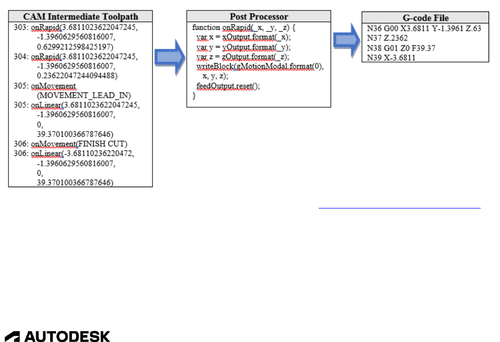
1.2 What is a Post Processor?
A post processor, sometimes simply referred to as a "post", is the link between the CAM system and
your CNC machine. A CAM system will typically output a neutral intermediate file that contains
information about each toolpath operation like tool data, type of operation (drilling, milling, turning,
etc.), and tool center line data. This intermediate file is fed into the post processor where it's translated
into the language that a CNC machine understands. In most cases this language is a form of ISO/EIA
standard G-code, even though some controls have their own proprietary language or use a more
conversational language. All examples in this manual uses the ISO/EIA G-code format.
If you would like a bit more information on the G-code format the Fundamentals of CNC Machining
guide contains a lot of useful information including a further explanation of the G-code format in
Chapter 5 CNC Programming Language.
Though most controls recognize the G-code format the machine configuration can be different and some
codes could be supported on one machine and not another, or the codes could be interpreted differently,
for example one machine may support circular interpolation while another requires linear moves to cut
the circle, which is why you will probably need a separate post processor for each of your machine tools.

Introduction to Post Processors 1-2
CAM Post Processor Guide 2/2/24
1.3 Finding a Post Processor
The first step in creating a post processor is to find an existing post that comes close to matching your
requirements and start with that post processor as a seed. You will never create a post processor from
scratch. You will find all the generic posts created by Autodesk on our online Post Library. From here
you can search for the machine you are looking for by the machine type, the manufacturer of the
machine or control, or by post processor name.
Other places to check for a post processor include the HSM Post Processor Forum or HSM Post
Processor Ideas.
It is possible that Autodesk has already created a post processor for your machine, but has not officially
released it yet. These posts are considered to be in Beta mode and are awaiting testing from the
community before placing into production. You can visit the HSM Post Processor Ideas site and search
for your post here. This site contains post processor requests from users and links to the posts that are in
Beta mode. You can search for your machine and/or controller to see if there is a post processor
available.

Introduction to Post Processors 1-3
CAM Post Processor Guide 2/2/24
Searching For a Post Processor on Ideas or the Forum
Beta Post Processor Found on HSM Post Processor Ideas
If your post processor is not found, then you should search the HSM Post Processor Forum using the
same method you used on the HSM Post Processor Ideas site. The Post Processor Forum is used by the
HSM community to ask questions and help each other out. It is possible that another user has created a
post to run your machine.
You should always take care when running output from a post processor for the first time on your
machine, no matter where the post processor comes from. Even though the post processor refers to
your exact name, it may be setup for options that your machine does not have or the output may not be
in the exact format that you are used to running on the machine.
1.4 Downloading and Installing a Post Processor
Once you find the post processor that closely matches your machine you will need to download it and
install it in a common folder on your computer. If you are working on a network with others then this
should be in a networked folder so everyone in your company has access to the same library of post
processors.

Introduction to Post Processors 1-4
CAM Post Processor Guide 2/2/24
Selecting the Local Post Processor Folder
When using Fusion it is recommended that you enable cloud posts and place it in your Asset Library.
This way post processors, tool libraries, and templates will be synched across devices and users at a
company.
Enabling Cloud Post Processors in Fusion

Introduction to Post Processors 1-5
CAM Post Processor Guide 2/2/24
Double Click the CAMPosts Folder and then Press the Upload Button
Once you have uploaded your post(s) to the Cloud Library you can access these from Fusion. You do
this by pressing the Setup button in the Post Process dialog and selecting your post from the dropdown
menu.
Selecting Your Post from the Cloud Library

Introduction to Post Processors 1-6
CAM Post Processor Guide 2/2/24
In all cases you will want to avoid placing posts in the production install folder as these can be
overwritten when HSM is updated. Downloading your posts to a separate folder means that you can
reduce your list of post processors that show up in the Post Process dialog to those that you use in your
shop.
1.4.1 Automatically Updating Your Post Processors
It is possible to have Fusion automatically search for the latest versions and additions of post processors
and machines when they become available. This is accomplished by enabling Automatically get latest
Posts, Machines and Print Settings in the Manufacture/Optional Features section of the User
Preferences.
Automatic Update of Post Processors
1.5 Running the Post Processor
The post processor can be run from the Post Process dialog or from an NC Program in Fusion. You can
either select the Post Process button or right click on an Operation/NC program and select Post Process
from the menu. Multiple operations can be selected and post processed in a single operation.
Introduction to Post Processors 1-7
CAM Post Processor Guide 2/2/24
Fusion Inventor HSMWorks Right Click
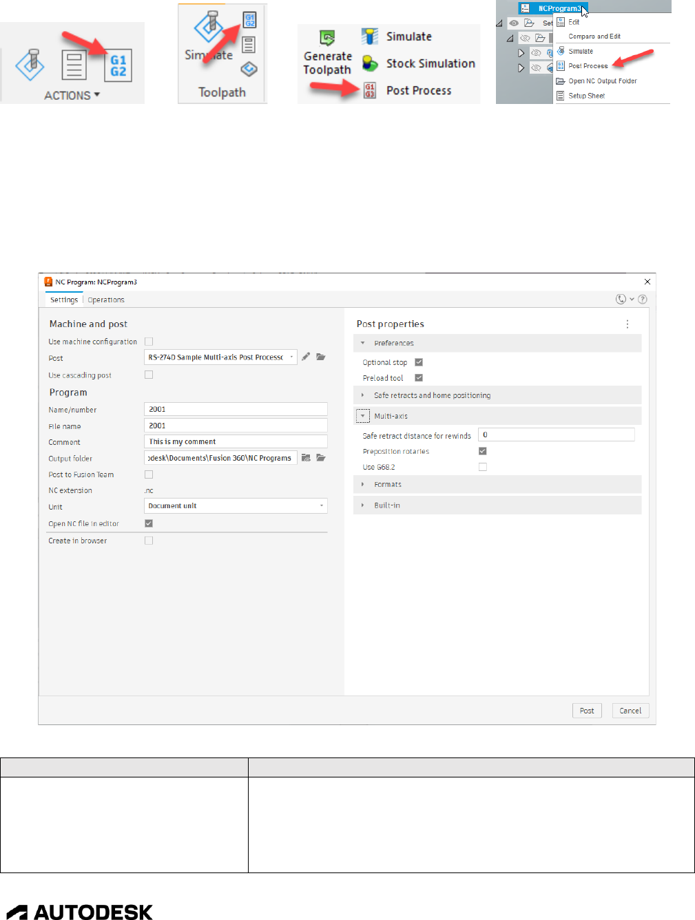
1.5.1 Post Process Dialog
Fusion uses the NC Programs dialog as its interface to the post processor, while Inventor CAM and
HSMWorks use the legacy Post Process dialog. The display of the Post properties in the NC Programs
dialog is more advanced, as it respects the group names from the property table and displays them in
collapsible tabs.
Fusion Post Process Dialog
Field
Description
Use machine configuration
Check this box to assign a Machine Definition to the post
processor. Typically, you would assign a Machine Definition to
the Manufacturing Setup in Fusion. If a machine is assigned to
the Manufacturing Setup, then this box will be checked and the
Machine Definition will be displayed below this field.

Introduction to Post Processors 1-8
CAM Post Processor Guide 2/2/24
Field
Description
Post
Specifies the post processor you want to run. The dropdown
arrow in this field will display a list of recently used post
processors. Pressing the button will open a popup dialog that
includes a list of linked folders and available posts that you can
select from. The button allows you to edit the post processor.
Use cascading post
Used to select a cascading post. A cascading post is usually a 3
rd
party post processor or verification program that is run after the
Fusion post processor.
Name or number
The name/number of the program. This name/number will
usually be output as the first line of the NC file, usually as an
Oxxxx code when a number is required or as a comment (xxxx)
if a name is allowed. The post processor controls whether an
alphanumeric name is allowed in this field or if a number must
be entered. This is defined by the programNameIsInteger =
true; statement in the post processor and can be set to either true
(number required) or false (alphanumeric name allowed).
File name
The output NC file name. This will default to the program
name/number.
Comment
The program comment, which is usually output as a comment at
the top of the NC file.
Output folder
Specifies the folder for the output NC file. Pressing the
button will open this folder in a File Explorer window. Pressing
the button opens a folder browser window to select the folder
for the NC file.
Post to Fusion Team
Saves the output file to the cloud. The Fusion Team output
folder field will be displayed if this box is checked, allowing you
to select the cloud folder to post to.
NC extension
Contains the default file extension for the output NC file as
defined in the post processor. You cannot override the file
extension.
Unit
Controls the output units of the NC file. This is usually set to
use the same units as the model, but can be overridden to output
in either Inch or Millimeters.
Open NC file in editor
Check this box if you want to open the output NC file in an
editor after post processing is finished. The editor used is
defined in your Fusion Preferences dialog in the General-
>Manufacture-> External editor field.
Create in browser
Check this box if you want an NC Program automatically
created with the operations you are posting against. Be
forewarned, if this box remains checked each time you post
process outside of an NC Program, then you will continue to get
new NC Programs added to the list.
Property Table
Displays the properties defined in the post processor and allows
you to modify these properties. Please see the Property Table
Introduction to Post Processors 1-9
CAM Post Processor Guide 2/2/24
Field
Description
section in this manual for a full description of post processor
properties.
Fusion Post Process Dialog Fields
Selecting a Post Processor in Fusion
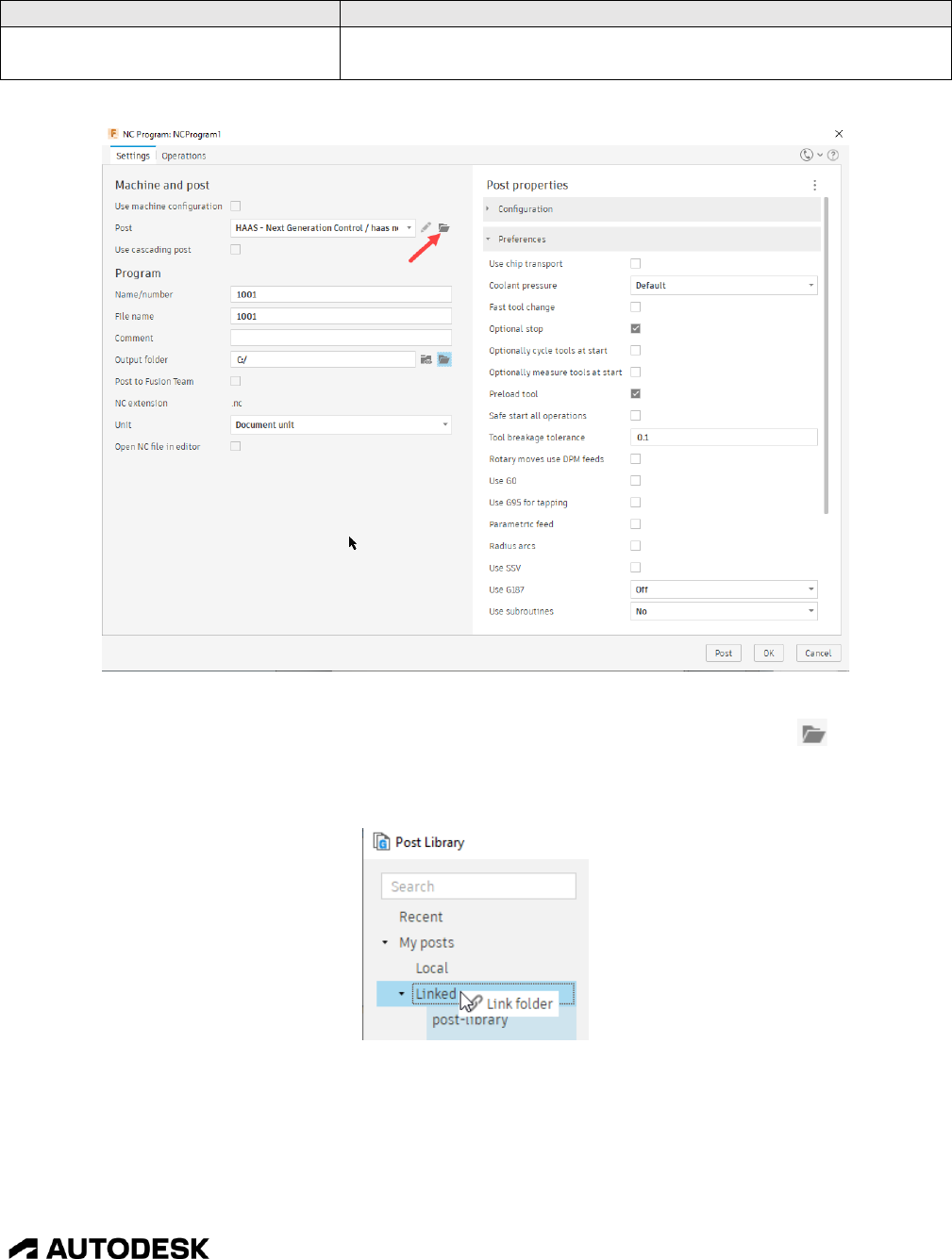
You select the folder for the post processor and the post processor itself by pressing the button next
to the Post field. You can right click on the Linked menu in the Post Library dialog to add a new folder
to select post processors from. The new folder will be displayed in the Linked menu.
Selecting a New Folder for Post Processors

Introduction to Post Processors 1-10
CAM Post Processor Guide 2/2/24
Inventor CAM and HSMWorks Legacy Post Process Dialog
Field
Description
Configuration Folder
Specifies the folder location of the post processor you want to
run. You can press the button to open a folder browser
window to select the post processor. This field is only displayed
in the legacy dialog, but you can select the folder in the NC
Programs dialog by pressing the button next to the Post field.
Setup
Used to select preinstalled post processor libraries or to select a
cascading post. A cascading post is usually a 3
rd
party post
processor or verification program that is run after the HSM post
processor. This field is only displayed in the legacy dialog.
Post Configuration
Defines the post processor you want to run. The available posts
are listed in a dropdown menu. There are filters that will limit
the post processors listed, including a Search Text field,
Capabilities (milling, turning, etc.), and Vendors.
Output folder
Specifies the folder for the output NC file. Pressing the
button opens a folder browser window to select the folder for the
NC file. The Open folder button opens a file browser in this
folder.
NC extension
Contains the default file extension for the output NC file as
defined in the post processor. You can override the file
extension in this field.

Introduction to Post Processors 1-11
CAM Post Processor Guide 2/2/24
Field
Description
Program name or number
The name/number of the output NC file. This name/number will
usually be output as the first line of the NC file, usually as an
Oxxxx code when a number is required or as a comment (xxxx)
if a name is allowed. The post processor controls whether an
alphanumeric name is allowed in this field or if a number must
be entered. This is defined by the programNameIsInteger =
true; statement in the post processor and can be set to either true
(number required) or false (alphanumeric name allowed).
Program comment
This field is output as a comment at the top of the NC file.
Unit
Controls the output units of the NC file. This is usually set to
use the same units as the model, but can be overridden to output
in either Inch or Millimeters.
Reorder to minimize tool changes
Check this box if you are running with multiple setups and you
want the operations with the same tool numbers to be placed
together to minimize tool changes. Operations within the same
setup will not be reordered.
Open NC file in editor
Check this box if you want to open the output NC file in an
editor after post processing is finished. The editor used is
defined in the Preferences dialog in the General->Manufacture-
> External editor field.
Property Table
Displays the properties defined in the post processor and allows
you to modify these properties. Please see the Property Table
section in this manual for a full description of post processor
properties.
Inventor/HSMWorks Post Process Dialog Fields
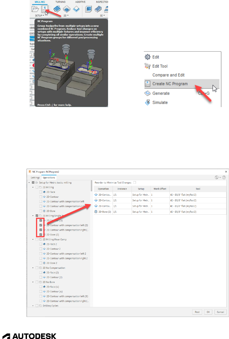
1.5.2 NC Programs
NC Programs are supported in Fusion and allow you to group operations together and assign a post
processor that is used for these operations. You create an NC Program by pressing the NC Program
menu or right clicking on a (group of) operation(s) and selecting Create NC Program from the list.
Pressing the Post Process button will bring up the NC Program dialog where you can create an NC
Program from the selected operations when the Post or OK button are pressed. It is important to note
that pressing the OK button will NOT post process the NC Program but will only save it.
Introduction to Post Processors 1-12
CAM Post Processor Guide 2/2/24
NC Program Button Right Click to Create NC Program
The NC Program dialog contains two tabs, Settings and Operations. This is the same dialog that is
displayed when Post Processing from the menus.
You will also notice that when you post process against an NC Program that the NC Program dialog is
displayed. If you want to change any settings for post processing when using an NC Program, you must
edit the NC Program to make changes.
Selecting Operations for an NC Program

Introduction to Post Processors 1-13
CAM Post Processor Guide 2/2/24
1.5.3 Machine Definitions
Machine Definitions can be used to define the kinematics and multi-axis capabilities of the machine for
both the post processor and machine simulation. A Machine Definition is assigned to a Setup in the
CAM system. The usage of a Machine Definition has distinct advantages.
1. Allows a single generic post processor to be used for multiple machines with different
kinematics.
2. The post processor is assigned directly to the Machine Definition.
3. The NC output folder is defined in the Machine Definition.
4. Defines the unique multi-axis features for the machine.
5. Required for Machine Simulation.
6. Required for Operation Properties.
You can determine if a post processor supports a Machine Definition by checking for the
activateMachine function inside of the post processor. If this function is not present, then the post
processor will most likely not accept or fully support a Machine Definition. There are a number of post
processors that support Machine Definitions, such as the Fanuc, Haas Next Generation, Heidenhain,
Hurco, Siemens, and Tormach posts.
You assign a Machine Definition to a CAM Setup when creating or editing the Setup and pressing the
Select… button. This will bring up the Machine Library dialog that allows you to select a machine from
the available configurations.
Selecting a Machine Definition
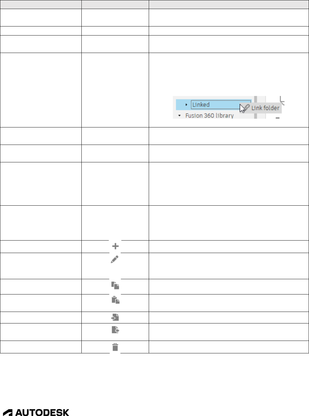
The Machine Library dialog consists of the following areas.
Introduction to Post Processors 1-14
CAM Post Processor Guide 2/2/24
Area
Item
Description
Location of Machine
Definitions
Specifies the area you want to select a Machine
Definition from.
Recent
Displays recently selected Machine Definitions.
Document
Displays Machine Definitions used in the active
model.
My machines
Displays Machine Definitions stored locally on
your computer or in selected (linked) folders. You
can add folders to the linked area by right clicking
on the Linked menu and selecting Link folder.
Fusion Library
Displays all Machine Definitions included with
Fusion.
Machine Definitions
Lists the Machine Definitions stored in the
selected location.
Filters and Machine
Definition Description
The Filter tab allows you to filter the Machine
Definitions based on Capabilities, Machine
Simulation Ready, and Vendor. The Info tab
displays information about the selected Machine
Definition.
Editing Menu
Contains buttons for creating, editing, copying,
and deleting Machine Definitions. Right clicking
on a Machine Definition will also display this
menu.
Creates a new Machine Definition.
Edits an existing Machine Definition. The
Machine Definition must reside in one of the My
machines folders.
Copies the selected Machine Definition.
Pastes the selected Machine Definition into the
selected folder.
Imports an external Machine Definition file.
Exports the selected Machine Definition to an
external file.
Deletes the selected Machine Definition.
Machine Library Dialog
Once you find the Machine Definition you want to use you can copy it into your Local folder or a
Linked Folder. You can do this by dragging the definition onto the desired My machines folder or by

Introduction to Post Processors 1-15
CAM Post Processor Guide 2/2/24
copying and pasting it into the desired folder. You can only edit Machine Definitions stored in one of
the My machines folders.
The latest versions of Machine Definitions are available on our online Post Library. From here you can
search for the machine by the machine type, the manufacturer of the machine, or by machine name.
Online Machine Library
Once a Machine Definition is selected, you can edit it by pressing the Edit... button in the Setup dialog.

Introduction to Post Processors 1-16
CAM Post Processor Guide 2/2/24
Editing/Creating a Machine Definition
The areas of the Machine Definition that are important for post processing are the General, Kinematics,
Post Processing, and Multi-Axis settings. The information in the other areas can be accessed by the post
processor, but not all are used by the library post processors as of this writing.
Area
Description
General
Describes the manufacture, machine model, and description of the configuration.
Kinematics
Defines the machine kinematics of the moving axes. You can define up to 3 linear axes,
2 rotary axes, a single spindle, and a table. You can add and axis by pressing the
icon. When you add an axis, it will be added after the highlighted component. An axis
can be deleted by highlighting it and pressing the icon.
The definition of the selected axis is displayed in the right pane of the dialog, including
the name, home position, feedrates, preference, and TCP setting.
The rotation vector (orientation) and range of the axis is defined below the kinematics
diagram.

Introduction to Post Processors 1-17
CAM Post Processor Guide 2/2/24
Area
Description
The rotary axis pivot location (Offset) and initial location at the start of an operation
(Reset) are located under the Advanced settings tab.
These fields apply directly to the parameters of the createAxis function as described in
the Multi-Axis Post Processors chapter.
Post
Processing
This is where you will select the location of the post processor, the post processor itself,
and the output folder for the NC file. These will become the defaults when post
processing and for NC Programs.
Multi-Axis
Defines the multi-axis capabilities of the control, along with how retract/reconfigure
operations are handled, and singularity settings. These capabilities are described in the
Multi-Axis Post Processors chapter.
Machine Definitin Post Processor Settings
1.6 Creating/Modifying a Post Processor
Once you find a post processor that is close, but not exact to the requirements of your machine you will
need to make modifications to it. The good news is, all of posts are open source and can be modified
without limitation to create the post you need. You have a few options for making the modifications.
1. Make the modifications yourself using this manual as a guide and by asking for assistance from
the HSM community on the HSM Post Processor Forum.
2. Visit HSM Post Processor Ideas and create a request for a post processor for your machine.
Other users can vote for your request for Autodesk to create and add your post to our library.
3. Contact one of our CAM partners who offer post customization services. These partners can be
found on the HSM Post Processor Forum at the top of the page.

Introduction to Post Processors 1-18
CAM Post Processor Guide 2/2/24
Finding HSM CAM Partners
No matter which method you decide to use to create your post processor, you should have enough
information available to define the requirements, which includes as much of the following as you can
gather.
1. A post processor (.cps) that will be used as the seed post.
2. Sample NC code that has run on your machine.
3. The machine/control make and model.
4. The type of machine (mill, lathe, mill/turn, waterjet, etc.).
5. The machine configuration, including linear axes, rotary axes setup, etc.
6. A programming manual for your machine/control.
1.7 Testing your Post Processor – Benchmark Parts
When testing your post processor, you will need a part with cutting operations to post against. We have
created standard benchmark parts for this specific purpose. These parts cover the most common
scenarios you will come across when testing a post processor and are available for HSMWorks, Inventor
CAM, and Fusion CAM. They are available in both metric and inch format for all three CAM systems.
There are five different benchmark parts.
• Milling
• Turning and Mill/Turn
• Stock Transfers
• Waterjet-Laser-Plasma
• Probing

Introduction to Post Processors 1-19
CAM Post Processor Guide 2/2/24
1.7.1 Locating the Benchmark Parts
The benchmark parts are available to all users of Autodesk CAM and can be accessed in the Samples
folder for each product.
HSMWorks Sample Parts
C:\Program Files\HSMWorks\examples
Inventor CAM Sample Parts
C:\Users\Public\Public Documents\Autodesk\Inventor CAM\Examples

Introduction to Post Processors 1-20
CAM Post Processor Guide 2/2/24
Fusion CAM
Select the Data Panel and Double Click on CAM Samples
Fusion CAM (continued)
Double Click on Post Processor to Display the Sample Parts
1.7.2 Milling Benchmark Part
The milling benchmark parts include the following strategies.
• 2D

Introduction to Post Processors 1-21
CAM Post Processor Guide 2/2/24
• Drilling
• Coolant codes
• Manual NC commands
• 3+2 5-axis
• 5-axis simultaneous
Mill Benchmark Part
1.7.3 Mill/Turn Benchmark Part
The mill/turn benchmark parts contain the following strategies.
• Primary and Secondary spindle operations
• Turning
• Axial milling
• Radial milling
• 5-axis milling
Introduction to Post Processors 1-22
CAM Post Processor Guide 2/2/24
Turning and Mill/Turn Benchmark Part
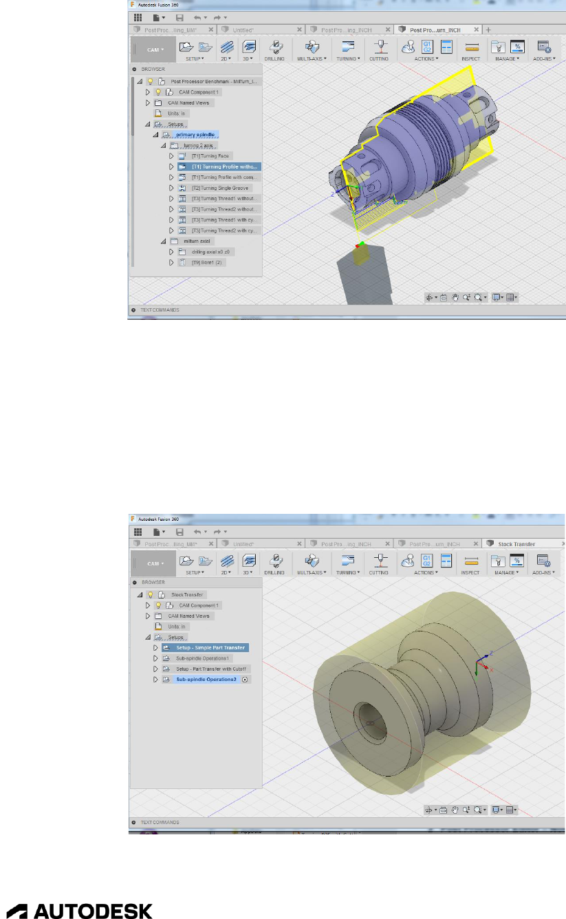
1.7.4 Stock Transfer Benchmark Part
The stock transfer benchmark part contains the following strategies.
• Primary and Secondary spindle operations
• Simple part transfer
• Part transfer with cutoff
Stock Transfer Benchmark Part

Introduction to Post Processors 1-23
CAM Post Processor Guide 2/2/24
The Waterjet-Laser-Plasma benchmark part contains the following strategies.
• Waterjet
• Laser
• Plasma
• Lead in/out
• Radius compensation
Waterjet-Laser-Plasma Benchmark Part
1.7.5 Probing Benchmark Part
The Probing benchmark part contains the following strategies.
• Various probing cycles

Autodesk Post Processor Editor 2-24
CAM Post Processor Guide 2/2/24
Probing Benchmark Part
2 Autodesk Post Processor Editor
Since Fusion, Inventor CAM, and HSMWorks post processors are text-based JavaScript code, they can
be edited with any text editor that you are familiar with. There are various editors in the marketplace
that have been optimized for working with programming code such as JavaScript. We recommend
Visual Studio Code with the Autodesk Fusion Post Processor Utility extension. Using this editor
provides the following benefits when working with Autodesk post processors.
• Color coding
• Automatic closing and matching of parenthesis and brackets
• Automatic indentation
• Intelligent code completion
• Automatic syntax checking
• Function List
• Run the post processor directly from editor
• Match the output NC file line to the post processor command that created it
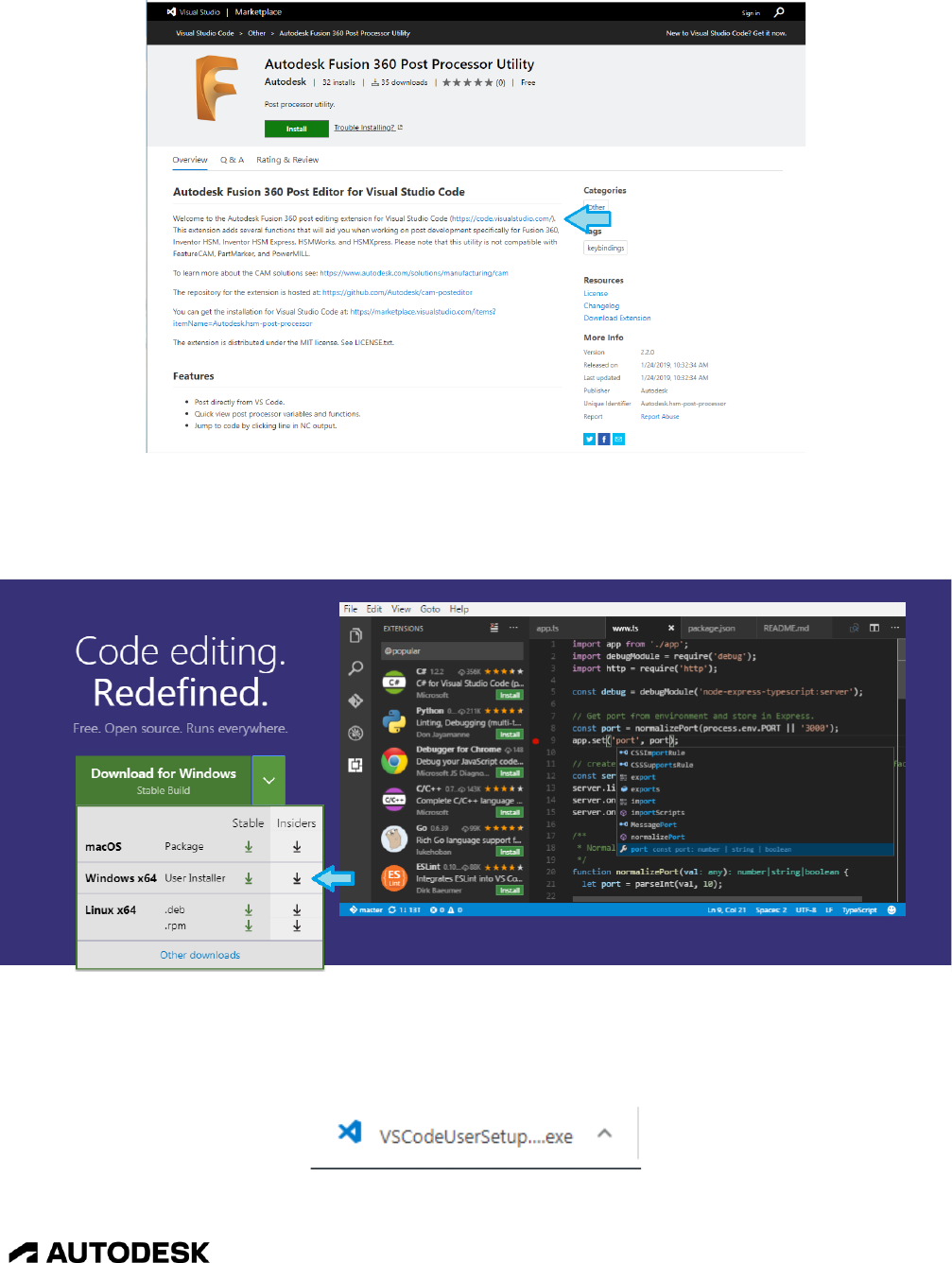
2.1 Installing the Autodesk Post Processor Editor
Before you can use the VSC editor you will need to install it. The easiest way is to visit the Autodesk
Fusion Post Processor Utility page in the Visual Studio Marketplace, where you can download VSC and
then the Autodesk Fusion Post Processor Utility extension. Please note that the Visual Studio Code site
changes quite frequently, so the directions/pictures in this section might not be exactly what you see on
the screen, but the installation steps should still be similar.
Autodesk Post Processor Editor 2-25
CAM Post Processor Guide 2/2/24
Installing Visual Studio Code
This link will take you to the Visual Studio Code installation page. Select the correct version for your
operating system.
Installing the Windows Version of Visual Studio Code
This will download an installation program that you can run to do the actual install. Left click on the
installation program to execute it.
Click the Executable to Install VSC
Autodesk Post Processor Editor 2-26
CAM Post Processor Guide 2/2/24
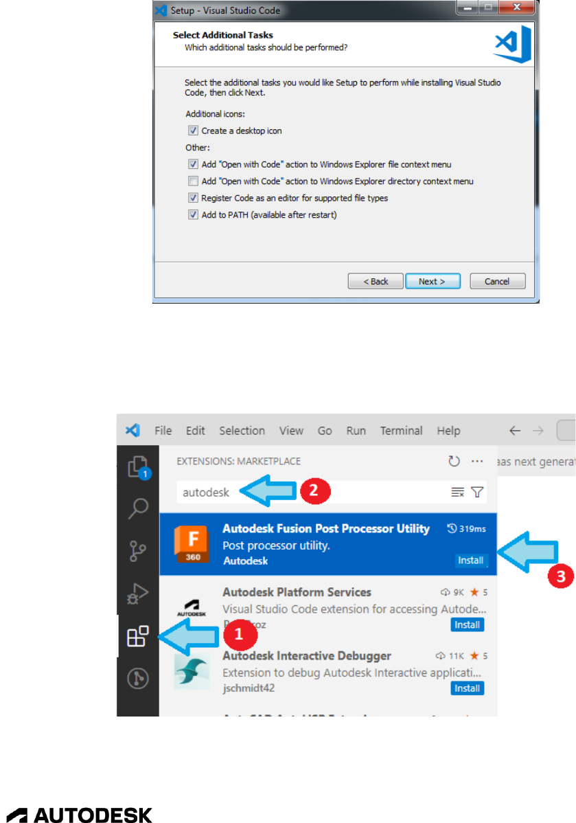
Follow the instructions displayed on the screen to finish the installation. You should select the defaults
for all questions, though you may want to make this the default code editor and add it to the Windows
Explorer file context menu.
Selecting Installation Options
You can choose to startup the Visual Studio Code editor automatically after it is installed. Once the
editor is opened you can install the Autodesk Fusion Post Processor Utility by opening the Extensions
view in the left pane and searching for Autodesk. Select the Autodesk Fusion Post Processor Utility to
install it.
Downloading the Autodesk Fusion Post Processor Extension

Autodesk Post Processor Editor 2-27
CAM Post Processor Guide 2/2/24
Installing the Autodesk Fusion Post Processor Extension
After installing the Autodesk Fusion Post Processor Utility extension you will want to exit the VSC
editor and then restart it so that the extension is initialized. You are now ready to start editing Autodesk
post processors.
2.2 Autodesk Post Processor Settings
After installing the Autodesk Post Processor editor you will want to setup the editor to match your
preferences. Open the settings file by selecting File->Preferences->Settings. This section will describe
some of the most popular settings, but feel free to explore other settings at your leisure to find any that
you may want to change. The User Settings can also be displayed by using the Ctrl+Comma shortcut.
Displaying the Editor Settings
The settings will be displayed in a separate tab. You can now search for individual settings using the
Search bar. To display the Autodesk Fusion Post Processor Utility settings type in hsm in the search bar.

Autodesk Post Processor Editor 2-28
CAM Post Processor Guide 2/2/24
Modifying the Editor Settings
There is a description that explains the setting making it easy for you to make the changes.
The following table provides a list of some of the more common settings and their descriptions.
Setting
Description
Editor > Minimap
Controls if the minimap is shown. The
minimap is a small representation of the entire
file displayed on the right side of the window
and allows you to easily scroll through the file.
Editor: Font Size
Size of the editor font.
Editor: Font Weight
Weight (thickness) of the editor font.
Editor: Detect Indentation
Automatically detects the editor.tabSize and
editor.insertSpaces settings when opening a
file.
Editor: Insert Spaces
When checked, spaces will be inserted into the
file when the tab key is pressed.
Editor: Tab Size
Sets the number of spaces a tab is equal to. The
standard setting for Autodesk post processors is
2.
Editor > Parameter Hints
Enables a pop-up that shows parameter
documentation and style information as you
type.
Editor: Auto Closing Brackets
Controls if the editor should automatically close
brackets after opening them.
Extensions: Auto Check Update or Auto Updates
Automatically (check for) update extensions.
Files: Associations
Associates file types with a programming
language. This must have "*.cps": "javascript"

Autodesk Post Processor Editor 2-29
CAM Post Processor Guide 2/2/24
Setting
Description
set in it to enable the automatic features of the
editor in Autodesk post processors.
Workbench: Color Theme
Defines the color theme for the editor. This
setting can be changed using the File-
>Preferences->Color theme menu.
HSMPost Utility: Auto Update Function List
Updates the function list automatically, without
the need for refreshing.
HSMPost Utility: Sort Function List Alphabetically
When checked the function list will be sorted.
Unchecked will display the function names in
the order that they are defined.
HSMPost Utility: Color Output
When checked, rapid, feedrate, and circular
blocks will be displayed in color.
HSMPost Utility: Rapid Color
Color for rapid move blocks.
HSMPost Utility: Linear Color
Color for feedrate move blocks.
HSMPost Utility: Circular Color
Color for circular move blocks.
HSMPost Utility: Enable Auto Line Selection
Enables the automatic selection of the line in
the post processor that generated the selected
line in the output NC file.
HSMPost Utility: Output Units
Sets the desired output units when post
processing
HSMPost Utility: Shorten Output Code
Limits the number of blocks output when
posting, making it easier to navigate.
HSMPost Utility: Post On CNCSelection
When checked, post processing will occur as
soon as a CNC file is selected.
HSMPost Utility: Post On Save
Automatically run the post processor when it is
saved, only if the NC output file window is
open.
Commonly Changed User Settings
2.3 Left Side Flyout
On the left side of the editor window is a tab that will open different flyout dialogs. The features
contained in the flyout dialogs are quite beneficial while editing a post processor and are explained in
this section. The Source Control flyout is not used when editing post processors and will not be
discussed.

Autodesk Post Processor Editor 2-30
CAM Post Processor Guide 2/2/24
Left Side Flyout Dialog
2.3.1 Explorer Flyout
The Explorer flyout contains expandable lists that are used to display the open editors, folders, variables,
functions, and CNC selector. The arrow ► at the left of each entry is used to expand or collapse the list.
List
Description
OPEN EDITORS
Lists the files that are open in this instance of the
VSC editor. Any files that have been changed,
but not been saved will be marked with a bullet
(•). The number of changed files that have not
been saved is displayed in the Explorer icon.
NO FOLDERS OPEN
You can open a folder for quick access to all of
the post processors in the folder. Expanding the
folders will display the Open Folder button that
can be used to open a folder. Clicking on a file in
the open folder will automatically open it in the
editor. Take note that if a folder is opened, then
all opened files in the editor will first be closed
and you will be prompted to save any that have
been changed.
OUTLINE
Lists the functions defined in the post processor
and the variables defined in each function.
Expanding the function by pressing the arrow ►
to the left of the function name will display the
variables defined in the function. You can select
any of the variables to go to the line where it is
defined.

Autodesk Post Processor Editor 2-31
CAM Post Processor Guide 2/2/24
List
Description
CNC SELECTOR
Contains the Autodesk intermediate files (*.cnc)
that are available to the post processor from the
VSC editor. This list is further explained in the
Running/Debugging the Post section of this
chapter.
FUNCTION LIST
Expanding the function list will display the
functions defined in the active post processor.
The functions will either be listed in alphabetical
order or by the order they appear in the post
processor depending on the HSMPost Utility:
Sort Function List Alphabetically setting. You
can select on a function in this list and the cursor
will be placed at the beginning of this function in
the editor window and while traversing through
the post processor the function that the cursor is
in will be marked with an arrow ►, making it
easy for you to determine what function the
active line is in.
POST PROPERTIES
Contains the Property Table for the post
processor, similar to the Property Table displayed
when running the post from CAM. This list is
further explained in the Running/Debugging the
Post section of this chapter.
VARIABLE LIST
Lists the variable types supported by the post
processor, such as Array, Format, Vector, etc. It
does not contain a list of variables defined in the
post processor. Expanding the variable type by
pressing the arrow ►to the left of it will display
the functions associated with the variable type.
Explore Flyout Selections
Open Editors Opening a Folder Open Folder File List
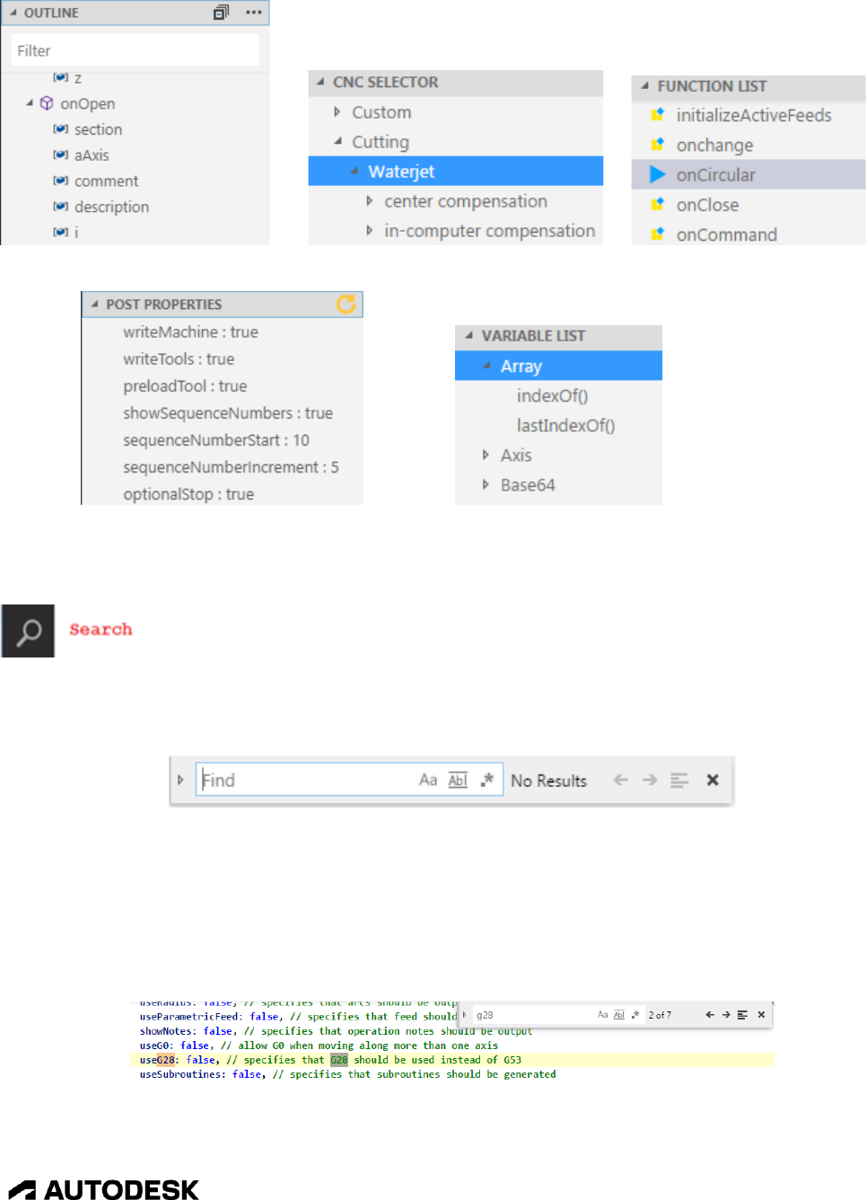
Autodesk Post Processor Editor 2-32
CAM Post Processor Guide 2/2/24
Outline CNC Selector Function List
Post Properties Variable List
2.3.2 Search Flyout
You can search for a text string in the current file or in all of the opened files. To search for the text
string in the current file you should use the Find popup window accessed by pressing the Ctrl+F keys.
Ctrl+F Find Popup – Search for a Text String in the Current File
As you type in a text string the editor will automatically display and highlight the next occurrence of the
text in the file. The number of occurrences of the text string in the file will be displayed to the right of
the text field. You can use the Enter key to search for the next occurrence of the string or press the
arrow keys to search forwards → and backwards ← through the file. If you use the Enter key, then the
keyboard focus must be in the Find field.
Using the Find Popup to Search for Text Strings
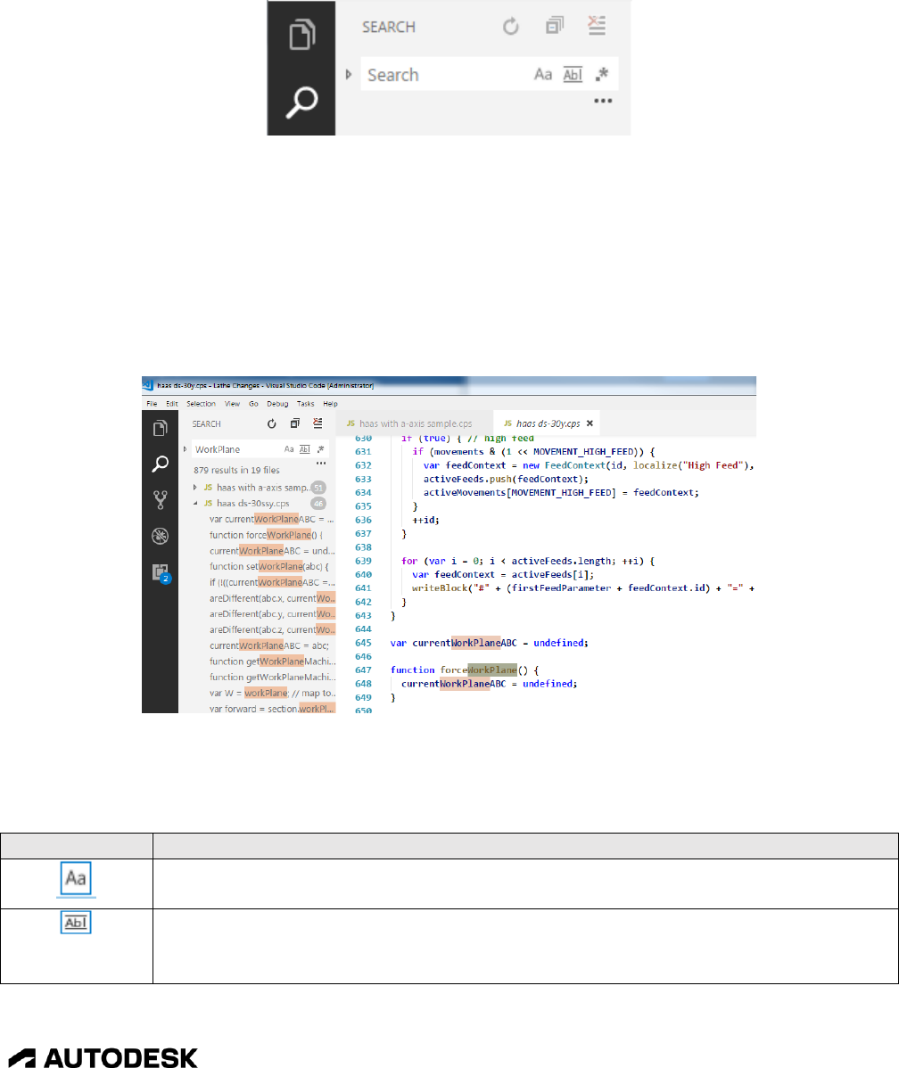
Autodesk Post Processor Editor 2-33
CAM Post Processor Guide 2/2/24
The Search flyout searches for a file in the opened files and in the files located in an open folder (refer
to the Explorer flyout to see how to open a folder). The Search dialog will be displayed when you press
the Search button.
Search Flyout – Search for a Text String in Multiple Files
Entering a text string to search for and then pressing the Enter key will display the files that contain the
text string and the number of instances of the text string in each file. You can expand the file in the list
by pressing the arrow key ► and each instance of the text string found in the selected file will be
displayed. Clicking on one of the instances causes the editor to go to that line in the file and
automatically open the file if it is not already opened. If you don't make any changes to the file and then
select the text string in another file, then the first file will be closed before opening the next file. An
unchanged file opened from the Search flyout will have its name italicized in the editor window.
Searching for a Text String in the Opened Files
There are options that are available when searching for text strings. These options are controlled using
the icons in the Search dialog and Find popup.
Icon
Description
When enabled, the case of the search string must be the same as the matching text
string in the file.
When enabled, the entire word of the matching text string in the file must be the
same as search string. When disabled, it will search for the occurrence of the search
string within words.

Autodesk Post Processor Editor 2-34
CAM Post Processor Guide 2/2/24
Icon
Description
When enabled, the '.' character can be used as a single character wildcard and the '*'
character can be used as a multi-character wildcard in the search string.
Search forward in the file. In the Find popup only.
Search backward in the file. In the Find popup only.
Searches for the text string only in the selected text in the file. In the Find popup
window only.
Closes the Find popup window.
Refresh the results window. In the Search flyout only.
Collapse all expanded files in the results window. In the Search flyout only.
Displays fields that allow you to include or exclude certain files from searches. In
the Search flyout only.
Displays the Replace field, allowing you to replace the Search text with the Replace
field text.
Replaces the current (highlighted) occurrence of the Search text with the Replace
field text. Hitting the Enter key while in the Replace field performs the same
replacement. In the Find popup window only.
Replaces all occurrences of the Search text with the Replace field text. When
initiated from the Search flyout, all occurrences of the text in all files listed in the
Results window will be replaced.
Search and Replace Options
2.3.3 Bookmarks Flyout
Okay, so the Bookmarks flyout is actually a Breakpoints flyout, but since JavaScript does not have an
interactive debugger we are going to use it for adding bookmarks to the opened files. Placing the cursor
to the left of the line number where you want to set a bookmark will display a red circle and then
clicking at this position will add the bookmark.
To see the active bookmarks you can open the Bookmarks flyout and expand the BreakPoints window.
You can then go directly to a line that is bookmarked by selecting that line in the Bookmarks flyout.
Bookmarks set in all opened files will be displayed in the flyout and the file that the bookmark is set in
will automatically be made the active window when the bookmark is selected.

Autodesk Post Processor Editor 2-35
CAM Post Processor Guide 2/2/24
Using the Bookmarks Flyout
2.3.4 Extensions Flyout
Visual Studio Code is an open-source editor and there are many extensions that have been added to it by
the community. For example, the Autodesk Fusion Post Processor Utility is an extension to this editor.
By opening the Extensions flyout you can see what extensions you have installed and what extensions
have updates waiting for them.
Viewing Installed Extensions
If there is an Update button displayed with the extension you can press this button to install the latest
version of the associated extension.
You can search the Visual Studio Marketplace for extensions that are beneficial for your editing style by
typing in a name in the Search Extensions in Marketplace field. For example, if you want a more
dedicated way to set bookmarks you can type in bookmark in this field and all extensions dealing with
adding bookmarks will be displayed. You can press the green Install button to install the extension.
You can also search for extensions online at the Visual Studio Marketplace.

Autodesk Post Processor Editor 2-36
CAM Post Processor Guide 2/2/24
Viewing Extensions in the Online Marketplace
2.4 Autodesk Post Processor Editor Features
The Autodesk Post Processor editor has features to enhance the ease of editing of post processor
JavaScript files. One example is the color coding of the text, variables are in one color, functions in
another, JavaScript reserved words in yet another, and so on. The colors of each entity is based on the
Workbench Color Theme setting.
This section will go over some of the more commonly used features. You are sure to discover other
features as you use the editor.
2.4.1 Auto Completion
As you type the name of a variable or function you will notice a popup window that will show you
previously used names that match the text as it is typed in. Selecting one of the suggestions by using the
arrow keys to highlight the name and then the tab key to select it will insert that name into the spot
where you are typing.
If the Editor: Parameter Hints setting is set to true, then when you type in the name of a function,
including the opening parenthesis, you will be supplied the names of the function's arguments for
reference.

Autodesk Post Processor Editor 2-37
CAM Post Processor Guide 2/2/24
Using Auto Completion
2.4.2 Syntax Checking
If you have a syntax error while editing a file, the editor is smart enough to flag the error by
incrementing the error count at the bottom left of the window footer and marking the problem in the file
with a red squiggly line. You can open the Problems window by selecting the X in the window footer to
see all lines that have a syntax error. Clicking on the line displaying the error will then take you directly
to that line, so that you can resolve the error.
You can close the window by pressing on the X in the window footer or the X at the top right of the
Problems window.
Displaying Syntax Errors
2.4.3 Hiding Sections of Code
You can hide code that is enclosed in braces {} by positioning the cursor to the right of the line number
on the line with the opening brace and then pressing the [-] icon. The code can be expanded again by
pressing the [+] icon. Note that the icons will not be displayed unless the cursor is placed in the area
between the line number and the editing window.
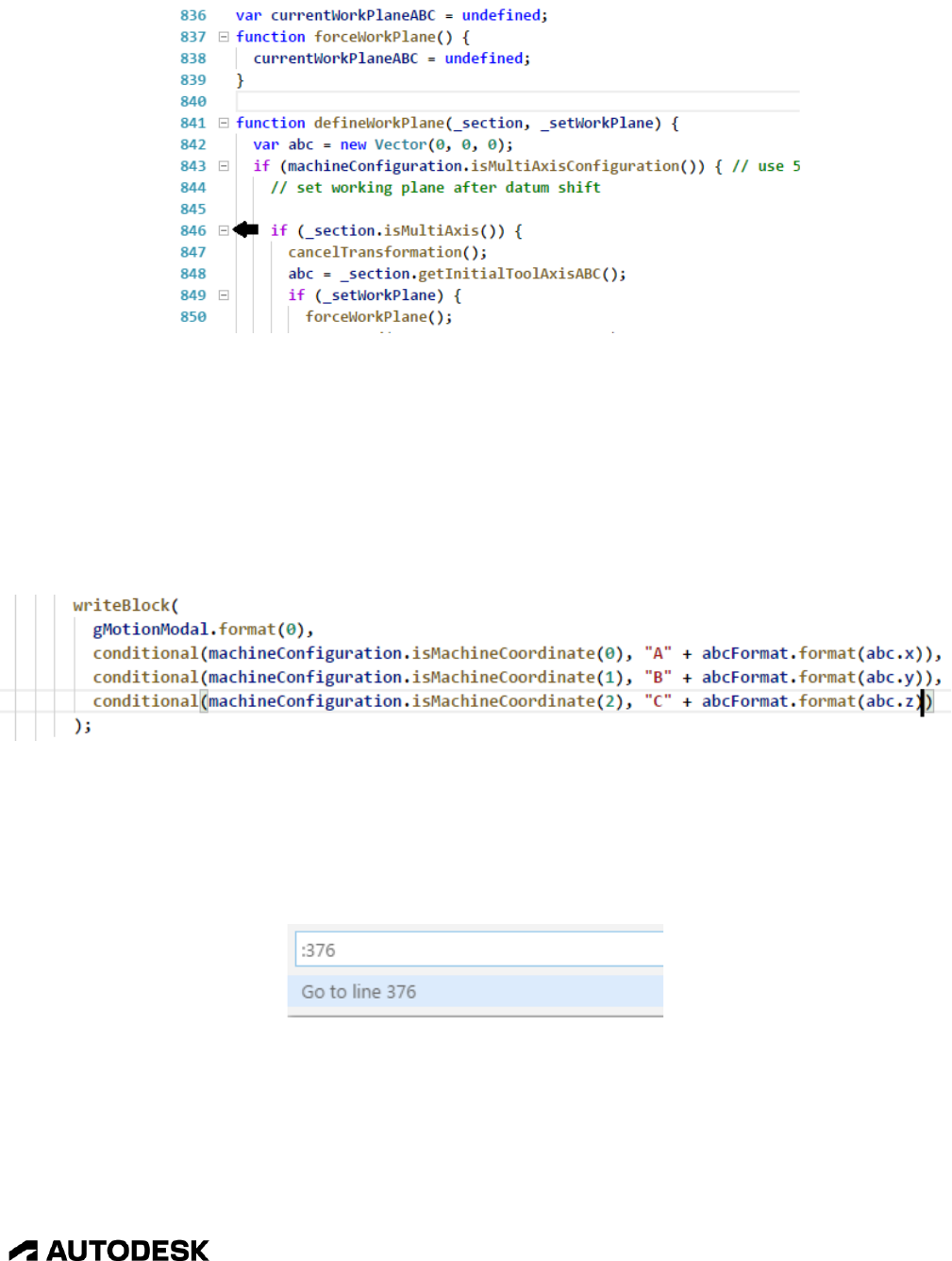
Autodesk Post Processor Editor 2-38
CAM Post Processor Guide 2/2/24
Hiding Sections of Code
2.4.4 Matching Brackets
If you place the edit cursor at a parenthesis (()), bracket ([]), or brace ({}) the editor will highlight the
selected enclosure as well as the opening/closing matching enclosure character. If there are multiple
enclosure characters right next to each other, then the enclosure following the edit cursor will be
selected. If the enclosure character does not highlight, then this means that there is not a matching
opening/closing enclosure.
Matching Parenthesis
2.4.5 Go to Line Number
You can go to a specific line number in the file by pressing the Ctrl+G keys and then typing in the line
number.
Go to Line Number
2.4.6 Opening a File in a Separate Window
You can open a file in the current window by selecting the File->Open File… menu from the task bar or
by pressing the Ctrl+O keys. You can open the active file in a separate VSC window by pressing the
Ctrl+K keys and then pressing the O key. The file will be opened in the a new window and remain open

Autodesk Post Processor Editor 2-39
CAM Post Processor Guide 2/2/24
in the active window. You can also open a new VSC window by selecting the File->New Window menu
or by pressing the Ctrl+Shift+N keys.
Open Separate VSC Window
2.4.7 Shortcut Keys
You can display the assigned Shortcut Keys by pressing the F1 key and then typing in key to display all
commands referencing the key string. Select the Preferences: Open Keyboard Shortcuts menu. You
can also press the Ctrl+K Ctrl+S keys in sequence to display the Shortcut Keys window.
Display the Shortcut Keys
Shortcut Key Assignments

Autodesk Post Processor Editor 2-40
CAM Post Processor Guide 2/2/24
Modifications and/or additions to the Shortcut Key assignments can be made by selecting the
keybindings.json link at the top of the page. This will open a split window display that displays the
default Shortcut Keys in the left window and the user defined Shortcut Keys in the right window. Use
the same procedure as modifying a setting to modify a Shortcut Key, by copying the binding definition
from the left window into the right window and making the desired changes. Be sure to save the
keybindings.json file after making your changes.
The format of the keystrokes that represent a single Shortcut is defined in the following table.
Shortcut
Sample
Description
key
F1
Press the single key.
key+key
Ctrl+Shift+Enter
key is the name of the key to press. The + character means that
the keys must be pressed at the same time. The + key is not
pressed.
key key
Ctrl+K Ctrl+S
The keys should be pressed in sequence, one after the other.
Each key can be a combination of multiple keys that are pressed
at the same time as explained above. Unless Shift is part of the
key sequence, then lower case letters are being specified.
Shorcut Key Syntax
2.4.8 Running Commands
The commands accessible by shortcut keys or the menus can be found and run from the command popup
dialog and are accessed in the editor by pressing the F1 key. Once the command popup is displayed you
can search for commands by typing in text in the search line. The commands that match the search will
be displayed along with the Shortcut Keys that are assigned to the commands. Select on the command to
run it.
Running a Command

Autodesk Post Processor Editor 2-41
CAM Post Processor Guide 2/2/24
2.5 Running/Debugging the Post
The Autodesk Fusion Post Processor Utility extension allows you to run the post processor that you are
editing directly from the editor and to debug the post by matching the output lines in the NC file with the
code line that generated the output. You can run the post against the provided intermediate files
generated from the Benchmark Parts or you can create your own intermediate file to run the post against.
2.5.1 Autodesk Post Processor Commands
There are built-in commands that pertain to running the post processor. These commands are accessed
by pressing the F1 key and typing HSM in the search field.
Displaying the Autodesk Post Processor Commands
The following table describes the available commands.
Command
Description
Post Utility
Displays a menu where you can post process the
selected intermediate (CNC) file against the open
post processor, select a new CNC file, or display
the Autodesk Post Help window. You can also
use the shortcut Ctrl+Alt+G to run the post
processor.
Change post executable
Sets the location of the post processor engine
executable.
Show debugged code
Displays the entry functions that are called and
the line numbers that generated the block in the
output NC file. This is the same output that is
displayed when you call the setWriteStack(true)
and setWriteInvocations(true) functions.
Delete CNC file
This command cannot be run from the
Commands menu. Right clicking on a CNC file
in the CNC Selection list and selecting Delete
CNC File will delete the file and remove it from
the list.
Disable auto line selection
Disables the feature of automatically displaying
the line in the post processor that generated the
selected line in the NC output file.
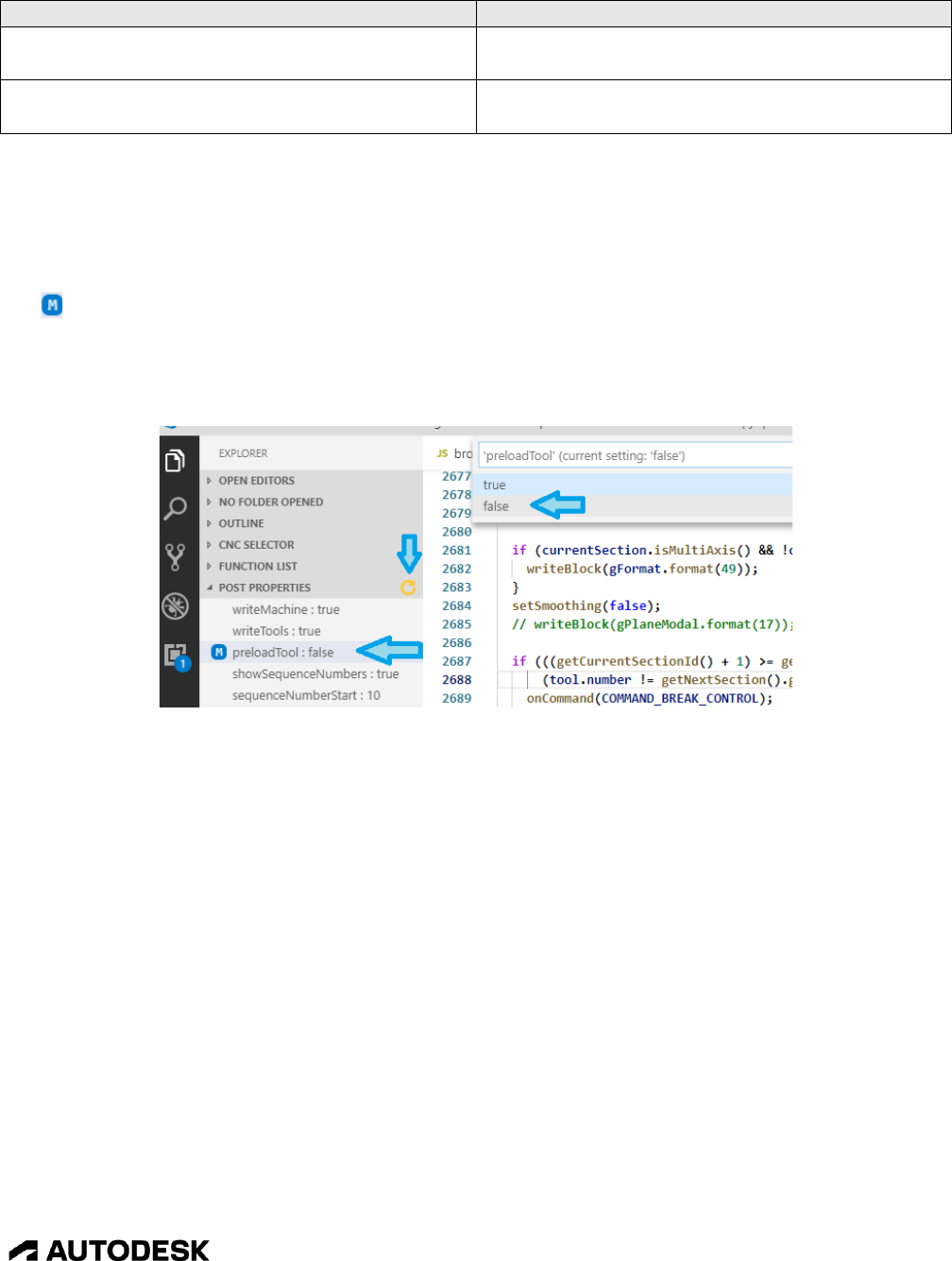
Autodesk Post Processor Editor 2-42
CAM Post Processor Guide 2/2/24
Command
Description
Download CNC exporting post processor
Downloads the Exporting Post Processor used
for generating your own CNC files for testing.
Post help
Displays the online AutoDesk CAM Post
Processor Documentation web page.
The Autodesk Post Processor Commands
2.5.2 The Post Processor Properties
You can display the properties associated with the open post processor by opening the Explorer flyout
and expanding the Post Properties list. Clicking on a property will prompt you to change the property.
The symbol will be displayed next to the property if it has been changed from the default value.
If you add a new property to the post or for some reason the properties don’t display, you can press the
yellow refresh symbol in the Post Properties header to refresh the displayed properties.
Modifying the Post Properties
2.5.3 Running the Post Processor
To run the post processor that is open in the editor you can use the Ctrl+Alt+G shortcut or run the Post
Utility from the Command window as described in the previous section. First you will need to select the
intermediate CNC file to run the post against. You select the CNC file by opening the Explorer flyout
and expanding the CNC Selector list until you find the desired CNC file.

Autodesk Post Processor Editor 2-43
CAM Post Processor Guide 2/2/24
Post the Selected CNC File Against the Active Post
You can also select the CNC file from the Post Utility menu.
Select the CNC File or Post Processor Using the Post Utility Command
If running a post processor for the first time in the editor it is possible that the location of the post engine
executable (post.exe) is not known. In this case you will see the following message displayed.
You can press the Browse… button to search for post.exe. The executable will be in one of the
following locations depending on the version of HSM being run.
HSM Version
Post Executable Location
Fusion
C:\User\username\AppData\Local\Autodesk\webdeploy\production\(id)\Applications\CAM360
username is your username that you logged in as. (id) is a unique and long name that changes
depending on the version of Fusion that you have installed. You will usually select the folder
with the latest date.
Inventor
C:\Program Files\Autodesk\Inventor CAM yyyy
yyyy is the version number (year) of Inventor.
HSMWorks
C:\Program Files\HSMWorks

Autodesk Post Processor Editor 2-44
CAM Post Processor Guide 2/2/24
Post Executable Locations
Once you have posted against the CNC file, the output NC file or Log file will be displayed in the right
panel of the split screen. When the HSMPostUtility: Enable Auto Line Selection setting is true, then
clicking twice on a line in the output NC file will highlight the line in the post processor that generated
the output. The second click must be on a different character on the same output line to highlight the
line. Then, by clicking on a different character in the same line you will be walked through the stack of
functions that were called in the generation of the output.
Output NC File, Click Twice on Output Line to See Code that Generated Output
2.5.4 Creating Your Own CNC Intermediate Files
The Autodesk Post Processor extension comes with built-in CNC intermediate files that are generated
using the HSM Benchmark Parts. These can be used for testing most aspects of the post processor, but
there are times when you will need to test specific scenarios. For these cases you can create your own
CNC file to use as input.
The Export CNC file to Visual Studio Code post processor from the Fusion Post Processor Library is
used to create external CNC intermediate files that can be used from within the Visual Studio Code
editor. You can download this post in the same manner as you download any post processor from
within Fusion.

Autodesk Post Processor Editor 2-45
CAM Post Processor Guide 2/2/24
Download the CNC Exporting Post Processor
Follow the directions in the Downloading and Installing a Post Processor section for installing a post
processor on your system.
Once the post processor is installed you will want to post process the operations you want to use for
testing. The CNC exporting post processor is run just like any other Autodesk post processor, except it
will not generate NC code, but will rather create a copy of the CNC file from the Autodesk CAM system
in a folder within the CNC Selector. The CNC file will be stored in the Custom folder by default, but
you can create your own private folder(s) by typing the custom folder name into the CNC output folder
field when post processing.
Selecting a Custom Folder for the Exported CNC File
Most posts use a number for the output file name, it is recommended that you give the CNC file a
unique name that describes the operations that were used to generate it.

JavaScript Overview 3-46
CAM Post Processor Guide 2/2/24
Create a Custom CNC Intermediate File
Once you click the yellow refresh button you should see the CNC file in the selected folder of the CNC
Selector list and can use it when post processing from the VSC editor. If you decide that you no longer
need a custom CNC intermediate file you can delete it by right clicking on the CNC file and select
Delete CNC File.
Using a Custom CNC Intermediate File Deleting a Custom CNC Intermediate File
3 JavaScript Overview
3.1 Overview
Autodesk post processors are written using the JavaScript language. It resembles the C, C++, and Java
programming languages, is interpreted rather than being a compiled language, and is object-orientated.
JavaScript as it is used for developing post processors is fairly simple to learn and understand, but still
retains its complex nature for more advanced programmers.
This chapter covers the basics of the JavaScript language and conventions used by Autodesk post
processors. There are many web sites that document the JavaScript language. The ELOQUENT
JAVASCRIPT site has a nicely laid out format. If you prefer a hard copy JavaScript guide, then the
JavaScript the Definitive Guide, Author: David Flanagan, Publisher: O’Reilly is recommended.
Whichever manual you use, you will want to focus on the core syntax of JavaScript and ignore the
browser and client-side aspects of the language.

JavaScript Overview 3-47
CAM Post Processor Guide 2/2/24
The Autodesk post processor documentation is provided as the post.chm file with HSMWorks and
Inventor CAM or you can visit the Autodesk CAM Post Processor Documentation web site. You will
find that the post.chm version of the documentation is easier to view, since it has a working Index.
3.2 JavaScript Syntax
JavaScript is a case sensitive language, meaning that all functions, variables, and any other identifiers
must always be typed exactly the same with regards to lower and uppercase letters.
currentCoolant = 7;
currentCoolant = 8;
currentcoolant = 9;
Case Sensitive Definition of 3 Different Variables
JavaScript ignores spaces and new lines between variables, operators, names, and delimiting characters.
Variable and function names cannot have spaces in them, as this would create separate entities.
Commands can be continued onto multiple lines and are terminated with a semicolon (;) to mark the end
of the logical command. If you are defining a string literal within quotes, then the literal should be
defined on a single line and not on multiple lines. If a text string is too long for a single line, then it
should be concatenated using an operation.
message = "The 3 inch bore needs to be probed prior to starting " +
"the next operation.";
Breaking Up a Text String onto Multiple Lines
There are two methods of defining comments in JavaScript. You can either enclose comments between
the /* and */ characters, which will treat all text between these delimiters as a comment, or place the //
characters prior to the comment text.
The /* comment */ format is typically used as the descriptive header of a function or to block out
multiple lines of code. Any characters on the line that follow the // characters are treated as a comment,
so you can have a single comment line or add a comment to the end of a JavaScript statement.
/**
Output a comment.
*/
function writeComment(text) {
writeln(formatComment(text)); // write out comment line
}
..
/*
switch (unit) {
case IN:
writeBlock(gUnitModal.format(20));
break;
case MM:

JavaScript Overview 3-48
CAM Post Processor Guide 2/2/24
writeBlock(gUnitModal.format(21));
break;
}
*/
Comment Lines
Using indentation for function contents, if blocks, loops and continuation lines is recommended as this
makes it easier to visualize the code. Tab characters, though supported by JavaScript, are discouraged
from being used. It is preferred to use virtual tab stops of two spaces for indenting code in post
processor code. Most editors, including the Autodesk Post Processor Editor can be setup to
automatically convert tab characters to spaces that will align each indent at two spaces. Please refer to
the Post Processor Editor chapter for an explanation on how to setup the Autodesk recommended editor.
function test (input) {
// indent 2 spaces inside of function
if (input == 1) {
writeBlock( // indent 2 more spaces in if block or loop
gAbsIncModal.format(90), // indent 2 more spaces for continuation lines
gMotionModal.format(0)
);
}
}
Indent Code 2 Spaces Inside Function, If Block, Loop, and Continuation Line
3.3 Variables
Variables are simply names associated with a value. The value can be a number, string, boolean, array,
or object. Variables in JavaScript are untyped, meaning that they are defined by the value that they have
assigned to them and the value type can change throughout the program. For example, you can assign a
number to a variable and later in the program you can assign the same variable a string value. The var
keyword is used to define a variable.
If a variable is not assigned a value, then it will be assigned the special value of undefined.
var a; // define variable 'a', it will have the value of undefined
var b = 1; // assign a value of 1 to the variable 'b'
var c = "text"; // assign a text string to the variable 'c'
c = 2.5; // 'c' now contains a number instead of string
Variable Definitions
While you can include multiple variable declarations on the same var line, this is against the standard
used for post processors and is not recommended. You can also implicitly create a variable simply by
assigning a value to the variable name without using the var keyword, but is also not recommended.
When declaring a new variable, be sure to not use the same name as a JavaScript or Post Kernel
keyword, for example do not name it var, for, cycle, currentSection, etc. Refer to the appropriate
documentation for a list of keywords/variables allocated in JavaScript or the Post Kernel.

JavaScript Overview 3-49
CAM Post Processor Guide 2/2/24
JavaScript supports both global variables and local variables. A global variable is defined outside the
scope of a function, for example at the top of the file prior to defining any functions. Global variables
are accessible to all functions within the program and will have the same value from function to
function. Local variables are only accessible from within the function that they are defined. You can
use the same name for local variables in multiple functions and they will each have their own unique
value in the separate functions. Unlike the C and C++ languages, local variables defined within an if
block or loop are accessible to the entire function and are not local to the block that they are defined in.
3.3.1 Numbers
Besides containing a standard numeric value, a variable assigned to a number creates a Number object.
For this discussion, we will consider an object a variable with associated functions. These functions are
specific to numbers and are listed in the following table.
Function
Description
Returns
toExponential(digits)
Format a number using exponential
notation
String representation of number
toFixed(digits)
Format a number with a fixed number
of digits
String representation of number
toLocaleString()
Format a number according to locale
conventions
String representation of number
toPrecision(digits)
Format a number using either a fixed
number of digits or using exponential
notation depending on value of
number
String representation of number
toString()
Format a number
String representation of number
Number Object Functions
var a = 12.12345;
b = a.toExponential(2); // b = "1.21e+1"
b = a.toFixed(3); // b = "12.123"
b = a.toString(); // b = "12.12345"
Sample Number Output
The JavaScript built-in Math object contains functions and constants that apply to numbers. The
following table lists the Math functions and constants that are most likely to be used in a post processor.
All Math functions return a value.
Function
Return value
Math.abs(x)
Absolute value of x
Math.acos(x)
Arc cosine of x in radians
Math.asin(x)
Arc sine of x in radians
Math.atan(x)
Arc tangent of x in radians
Math.atan2(y, x)
Counterclockwise angle between the positive X-axis and the point x,y in radians
Math.ceil(x)
Rounds up x to the next integer
Math.cos(x)
Cosine of x

JavaScript Overview 3-50
CAM Post Processor Guide 2/2/24
Function
Return value
Math.floor(x)
Rounds down x to the next integer
Math.max(args)
The maximum value of the input arguments
Math.min(args)
The minimum value of the input arguments
Math.PI
The value of PI, approximately 3.14159
Math.pow(x, y)
x raised to the power of y
Math.round(x)
Rounds x to the nearest integer
Math.sin(x)
Sine of x
Math.sqrt(x)
Square root of x
Math.tan(x)
Tangent of x
Math.NaN
The value corresponding to the not-a-number property
Math Object
a = Math.sqrt(4); // a = 2
a = Math.round(4.59); // a = 5
a = Math.floor(4.59); // a = 4
a = Math.PI; // a = 3.14159
a = Math.cos(toRad(45)); // a = .7071
a = toDeg(Math.acos(.866)); // a = 60
Sample Math Object Output
The Math trigonometric functions all work in radians. As a matter of fact, most functions that pass
angles in the post processor work in radians. There are kernel supplied functions that are available for
converting between radians and degrees. toDeg(x) returns the degree equivalent of the radian value x
and conversely the toRad(x) function returns the radian equivalent of the degree value x.
There are also standalone numeric functions that are not part of the Number of Math objects. These are
listed in the following table.
Function
Return value
parseFloat(value)
Parses value as a string argument and returns a real number.
Returns NaN if the string does not represent a valid number.
parseInt(value, radix)
Parses value as a string argument and returns an integer of the
specified radix. radix is typically defined as 10, but can be 2, 8,
16, etc. Returns NaN if the string does not represent a valid
integer.
spatial(value, unit)
Returns value converted to MM. unit specifies the units that value
is defined in and can be either MM or IN. The unit conversion
scale used is 25mm to 1in and not 25.4. This conversion creates a
more acceptable scaled value for display, for example 4in scales to
100mm instead of 101.6mm. The spatial function is typically used
to define the Built-in properties at the top of the post processor,
since they are referenced as MM in the post engine.
toPreciseUnit(value, unit)
Returns value converted to the output units. unit specifies the units
that value is defined in and can be either MM or IN A scale factor
of 25.4mm to 1in is used.

JavaScript Overview 3-51
CAM Post Processor Guide 2/2/24
Function
Return value
toUnit(value, unit)
Returns value converted to the output units. unit specifies the units
that value is defined in and can be either MM or IN. The unit
conversion scale used is 25mm to 1in and not 25.4.
Other Numeric Functions
3.3.2 Strings
Variables assigned a text string will create a String object, which contain a full complement of functions
that can be used to manipulate the string. These functions are specific to strings and are listed in the
following table. The table details the basic usage of these functions as you would use them in a post
processor. Some of the functions accept a RegExp object which is not covered in this manual, please
refer to dedicated JavaScript manual for a description of this object.
Function
Description
Returns
charAt(n)
Returns a single character at position n
The nth character
indexOf(substring, start)
Finds the substring within the string.
start is optional and specifies the
starting location within the string to
start the search at.
The location of the first occurrence of
substring within the string.
lastIndexOf(substring, start)
Finds the last occurrence of substring
within the string. start is optional and
specifies the starting location within
the string to start the search at.
The location of the last occurrence of
substring within the string.
length
Returns the length of the string.
length is not a function, but rather a
property of a string and does not use ()
in its syntax.
The length of the string
localeCompare(target)
Compares the string with target string.
A negative number if string is less
than target, 0 if the strings are
identical, and a positive number if
string is greater than target
replace(pattern, replacement)
Replaces the pattern text within the
string with the replacement text.
The updated string.
slice(start, end)
Creates a substring from the string
consisting of the start character up to,
but not including the end character of
the string.
A substring containing the text from
string starting at start and ending at
end-1. A negative value for start or
end specifies a position from the end
of the string; -1 is the last character, -2
is the second to last character, etc.
split(delimiter, limit)
Splits a string at each occurrence of
the delimiter string.
An array of strings created by splitting
string into substrings at the delimiter.
A maximum of limit substrings will be
created.
toLocaleLowerCase()
Converts the string to all lowercase
letters in a locale-specific method.
Lowercase string.
toLocaleUpperCase()
Converts the string to all uppercase
letters in a locale-specific method.
Uppercase string.
toLowerCase()
Converts the string to all lowercase
letters.
Lowercase string.

JavaScript Overview 3-52
CAM Post Processor Guide 2/2/24
Function
Description
Returns
toUpperCase()
Converts the string to all uppercase
letters.
Uppercase string.
String Object Functions
var a = "First, Second, Third";
b = a.charAt(3); // b = "s"
b = a.indexOf("Second"); // b = 7
b = a.length; // b = 20
b = a.localeCompare("ABC"); // b = 5;
b = a.replace(/,/g, "-"); // b = "First- Second- Third"
b = a.slice(0, -7); // b = "First, Second"
b = a.split(","); // b[0] = "First", b[1] = "Second", b[2] = "Third";
b = a.toLowerCase() ; // b = "first, second, third"
b = a.toUpperCase(); // b = "FIRST, SECOND, THIRD"
Sample String Output
3.3.3 Booleans
Booleans are the simplest of the variable types. They contain a value of either true of false, which are
JavaScript keywords.
var a = true; // 'a' is defined as a boolean
if (a) {
// processes the code in this if block since 'a' is 'true'
}
Sample Boolean Assignment
3.3.4 Arrays
An array is a composite data type that stores values in consecutive order. Each value stored in the array
is considered an element of the array and the position within an array is called an index. Each element
of an array can be any variable type and each element can have a different variable type than the other
elements in the array.
An array, like numbers and strings, are considered an object with functions associated with it. You can
define an array using two different methods, as an empty array using a new Array object, or by creating
an array literal with defined values for the array. You can specify the initial size of the array when
defining an Array object. The initial size of an array defined with values is the number of values
contained in the initialization.
var a = new Array(); // creates a blank array, all values are assigned undefined
var a = new Array(10); // creates a blank array with 10 elements
var a = [true, "a", 3.17]; // creates an array with the first 3 elements assigned
var a = [{x:1, y:2}, {x:3, y:4}, {x:5, y:6}]; // creates an array of 3 xy objects

JavaScript Overview 3-53
CAM Post Processor Guide 2/2/24
Array Definitions
You can access an array element by using the [ ] brackets. The name of the array will appear to the left
of the brackets and the index to the element within the array inside of the brackets. The index can be a
simple number or an equation.
var a = [1, 2, "text", false];
b = a[0]; // b = 1
a[5] = "next"; // a = [1, 2, "text", false, "next"]
b = a[2+a[0]]; // b = false;
Accessing Elements Within an Array
The Array object has the following functions associated with it.
Function
Description
Returns
concat(values)
Appends the values to an array.
Original array with concatenated
elements
join(separator)
Combines all elements of an array into
a string. separator is optional and
specifies the string used to separate the
elements of the array. The default is a
comma.
String containing array elements.
length
Returns the allocated size of the array.
length is not a function, but rather a
property of an array and does not use
() in its syntax.
The size of the array.
pop()
Pops the last element from the array
and decreases the size of the array by
1.
The value of the last element of the
array.
push(values)
Pushes the values onto the array and
increases the size of the array by the
number of values.
Updated size of array.
reverse()
Reverses the order of the elements of
the array.
Returns nothing, but rather modifies
the original array.
shift(values)
Removes the first element from the
array and decreases the size of the
array by 1.
The value of the first element of the
array.
slice(start, end)
Creates a new array consisting of the
start element up to, but not including
the end element of the array.
An array containing the elements from
array starting at start and ending at
end-1. A negative value for start or
end specifies a position from the end
of the array; -1 is the last element, -2
is the second to last element, etc.
sort(function)
Sorts the elements of the array. The
original array will be modified. The
sort method uses an alphabetical order
of elements converted to strings by
default. You can specify a function
that overrides the default sorting
algorithm.
The sorted array.
toLocaleString()
Format an array according to locale
conventions
String representation of array

JavaScript Overview 3-54
CAM Post Processor Guide 2/2/24
Function
Description
Returns
toString
Format an array
String representation of array
unshift()
Adds the values to the beginning of an
array and increases the size of the
array by the number of values.
Updated size of array.
Array Object Functions
var a = [1, 2, 3, 4, 5, 6, 7, 8];
b = a.concat(9, 10, 11); // b = [1, 2, 3, 4, 5, 6, 7, 8, 9, 10, 11]
b = a.join(", "); // b = "1, 2, 3, 4, 5, 6, 7, 8"
b = a.length; // b = 8
a.push(9, 10, 11) // a = [1, 2, 3, 4, 5, 6, 7, 8, 9, 10, 11]
b = a.pop(); // a = [1, 2, 3, 4, 5, 6, 7, 8, 9, 10], b = 10
a.reverse(); // a = [10, 9, 8, 7, 6, 5, 4, 3, 2, 1]
b = a.unshift(12, 11); // a = [12, 11, 10, 9, 8, 7, 6, 5, 4, 3, 2, 1], b = 12
b = a.shift(); // a = [11, 10, 9, 8, 7, 6, 5, 4, 3, 2, 1], b = 12
b = a.slice(4, 7); // b = [7, 6, 5]
a.sort(function(a, b) { // a = [1, 2, 3, 4, 5, 6, 7, 8, 9, 10, 11]
return a-b;
});
b = a.toString() // b = "1,2,3,4,5,6,7,8,9,10,11"
Sample Array Output
3.3.5 Objects
An Object is similar to an array in that it stores multiple values within a single variable. The difference
is that objects use a name for each sub-entity rather than relying on an index pointer into an array. The
properties table in a post processor is an object. You can define an object using two different methods,
explicitly using the Object keyword, or implicitly by creating an object literal with defined names and
values for the object. Each named entity within an object can be any type of variable, number, string,
array, boolean, and another object. Objects can also be stored in an array.
Objects can be expanded to include additional named elements at any time and are not limited to the
named elements when they are created. You can reference the elements within an object using either the
name of the element (object.element) or by using a text string or variable (object["element"]) as the
name of the element. The following examples all reference the moveTime element of the status object.
var status = {moveDistance:0, moveTime:0, feedrate:0};
…
writeln("Move time = " + status.moveTime);
writeln("Move time = “ + status["moveTime"];
var element = "moveTime";
writeln("Move time = " + status[element];
Referencing Elements Within an Object

JavaScript Overview 3-55
CAM Post Processor Guide 2/2/24
var a = new Object(); // creates a blank object, without named elements
var a = {x:1, y:2, z:3}; // creates an object for storing coordinates
a.feed = 10.0; // adds the 'feed' element to the 'a' Object
a["feed"] = 10.0; // an alternate method for referencing the 'feed' element.
var a = [{x:1, y:2}, {x:3, y:4}, {x:5, y:6}]; // creates an array of 3 xy objects
Object Definitions
3.3.6 The Vector Object
The Vector object is built-in to the post processor and is used to store and work with vectors. The vector
components are stored in the x, y, z elements of the Vector object. Certain post processor variables are
stored as vectors and some functions require vectors as input. A Vector object is created in the same
manner as any other object. Vector objects are typically used to store and work on vectors, spatial
points, and rotary angles.
var a = new Vector(); // creates a blank Vector object
var a = new Vector(1, 0, 0); // creates an X-axis vector {x:1, y:0, z:0}
a.x = -1; // assigns -1 to the x element of the vector
setWorkPlane(new Vector(0, 0, 0)); // defines a null vector inline
Sample Vector Definitions
The following tables describe the attributes and functions contained in the Vector object. Since an
attribute is simply a value contained in the Vector object, it does not have an argument.
Attribute
Description
abs
Contains the absolute coordinates of
the vector
length
Contains the length of the vector
length2
negated
Contains the negated vector
normalized
Contains the normalized/unit vector
x
Contains the X-component
y
Contains the Y component
z
Contains the Z component
Vector Attributes
You can directly modify an attribute of a vector, but if you do then the remaining attributes will not be
updated. For example, if you directly store a value in the x attribute, vec.x = .707, the length attribute of
the vector will not be updated. You should use the vec.setX(.707) method instead.
If the Returns column in the following table has Implicit, then there is no return value, rather the Vector
object associated with the function is modified implicitly. For this reason, if you are going to nest a
Vector function within an expression, do not use the Implicit function, but rather the equivalent function
that returns a vector.

JavaScript Overview 3-56
CAM Post Processor Guide 2/2/24
Function
Description
Returns
divide(value)
Divides each component of the object
vector by the value
Implicit
getCoordinate(coordinate)
Returns the value of the vector
component (0=x, 1=y, 2=z)
Component of vector
getMaximum()
Determines the largest component
value in the vector
Maximum component value
getMinimum()
Determines the minimum component
value in the vector
Minimum component value
getNegated()
Calculates the negated vector
Vector at 180 degrees to the object
vector (vector * -1)
getNormalized()
Calculates the normalized/unit vector
Normalized or unit vector
getX()
Returns the X-coordinate of the vector
X-coordinate
getXYAngle()
Calculates the angle of the vector in
the XY-plane
Angle of vector in XY-plane
getY()
Returns the Y-coordinate of the vector
Y-coordinate
getZ()
Returns the Z-coordinate of the vector
Z-coordinate
getZAngle()
Calculates the Z-angle of the vector
relative to the XY-plane
Z-angle of vector relative to the XY-
plane
isZero()
Determines if the vector is a null
vector (0,0,0)
True if it is a null vector
multiply(value)
Multiplies each component of the
vector by the value
Implicit
negate()
Multiplies each component of the
vector by -1. Creates a vector at 180
degrees to the object vector
Implicit
setCoordinate(coordinate, value)
Sets the value of the vector component
(0=x, 1=y, 2=z)
Implicit
setX()
Sets the X-coordinate of the vector
Implicit
setY()
Sets the Y-coordinate of the vector
Implicit
setZ()
Sets the Z-coordinate of the vector
Implicit
toDeg()
Converts radians to degrees
Angles in degrees
toRad()
Converts degrees to radians
Angles in radians
toString()
Formats the vector as a string, e.g.
"(1, 2, 3)"
String representation of vector
Vector Object Functions
Static functions do not require an associated Vector object.
Function
Description
Returns
Vector.cross(left, right)
Calculates the cross product of two
vectors
Vector perpendicular to the two
vectors
Vector.diff(left, right)
Calculates the difference between two
vectors
Left vector minus right vector
Vector.dot(left, right)
Calculates the dot product of the two
vectors
Cosine of angle between the two
vectors
Vector.getAbsolute()
Converts the vector components to
absolute values
Vector with absolute coordinates
Vector.getAngle()
Calculates the angle between two
vectors
Angle between the two vectors in
radians

JavaScript Overview 3-57
CAM Post Processor Guide 2/2/24
Function
Description
Returns
Vector.getDistance(left, right)
Calculates the distance between two
vectors. Typically used when the
vectors store XYZ spatial coordinates
rather than vectors.
Distance between two points
Vector.getDistance2(left,right)
Calculates the square of the distance
between two vectors.
Squared distance between two points.
Vector.lerp(left, right, u)
Calculates a point at a percentage of
the distance between the two
coordinates. 'u' specifies the
percentage of the distance to create the
point at.
Point at a percentage of the line
between two points
Vector.product(vector, value)
Multiplies each component of the
vector by the value
Vector * value
Vector.sum(left, right)
Adds the two vectors
Left vector plus right vector
Static Vector Functions
b = a.length(); // b = length of Vector a
c = Vector.getAngle(a, b) // c = angle in radians between vectors a and b
var a = new Vector(1, 2, 1.5);
d = a.getMaximum(); // d = 2
b = Vector.getDistance(point1, point2).normalized; // b = directional vector from point1 to point2
b = Vector.dot(vector1, vector2); // b = cosine of angle between vector1 & vector2
b = a.negated; // b = vector at 180 degrees to Vector a
Sample Vector Expressions
3.3.7 The Matrix Object
The Matrix object is built-in to the post processor and is used to store and work with matrices. Matrices
are normally used when working with multi-axis machines, for 3+2 operations and for adjusting the
coordinates for table rotations. Matrices in the post processor contain only the rotations for each axis
and do not contain translation values.
Certain post processor variables are stored as matrices, such as the workPlane variable, and some
functions require matrices as input. A Matrix object has functions that can be used when creating the
matrix and are not dependent on working with an existing matrix.
Assignment Function
Definition
Matrix()
Identity matrix (1,0,0, 0,1,0, 0,0,1)
Matrix(i1, j1, k1, i2, j2, k2, i3, j3, k3)
Canonical matrix
Matrix(scale)
Scale matrix
Matrix(right, up, forward)
Matrix using 3 vectors
Matrix(vector, angle)
Rotation matrix around the vector
Matrix Assignment Functions
var a = new Matrix(); // creates an identity matrix

JavaScript Overview 3-58
CAM Post Processor Guide 2/2/24
var a = new Vector(-1, 0, 0, 0,-1,0, 0,0, 1); // creates a matrix rotated 180 degrees in the XY-plane
var a = new Matrix(.5); // creates a half scale matrix
var a = new Matrix(new Vector(1, 0, 0), 30); // creates an X-rotation matrix of 30 degrees
Sample Matrix Definitions
The following tables describe the attributes and functions contained in the Matrix object. Since an
attribute is simply a value contained in the Matrix object, it does not have an argument.
Attribute
Description
forward
Contains the forward vector
n1
Contains the length of the row vectors
of this matrix
n2
Contains the square root of this matrix
vector lengths
Negated
Contains the negated matrix
right
Contains the right vector
transposed
Contains the inverse matrix
up
Contains the up vector
Matrix Attributes
You can directly modify an attribute of a matrix, but if you do then the remaining attributes will not be
updated. For example, if you directly store a vector in the forward attribute, the other attributes will not
be updated to reflect this modification. You should use the matrix.setForward(vector) method instead.
If the Returns column in the following table has Implicit, then there is no return value, rather the Matrix
object associated with the function is modified implicitly. For this reason, if you are going to nest a
Matrix function within an expression, do not use the Implicit function, but rather the equivalent function
that returns a matrix.
Function
Description
Returns
add(matrix)
Adds the specified matrix to this
matrix
Implicit
getColumn(column)
Retrieves the matrix column as a
vector
Vector containing the specified
column of this matrix
getElement(row, column)
Retrieves the matrix element as a
value
Value of this matrix element
getEuler2(convention)
Calculates the angles for the
specified Euler convention
Vector containing Euler angles of
this matrix. Refer to the Work Plane
section of the manual for a
description of Euler conventions.
getForward()
Returns the forward vector. This will
be 0,0,1 in an identity matrix
Forward vector of this matrix
getN1()
Returns the length of the row vectors
of this matrix
Returns right_vector + up_vector +
forward_vector of matrix
getN2()
Returns the square root of this matrix
vector lengths
Math.sqrt(n1)
getNegated()
Calculates the negated matrix
Matrix * -1.
getRight()
Returns the right vector. This will be
1,0,0 in an identity matrix
Right vector of matrix

JavaScript Overview 3-59
CAM Post Processor Guide 2/2/24
Function
Description
Returns
getRow(row)
Retrieves the matrix row as a vector
Vector containing the specified row
of this matrix
getTiltAndTilt(first, second)
Calculates the X & Y rotations
around the fixed frame to match the
forward direction. 'first' and 'second'
can be 0 or 1 and must be different.
Calculated forward direction of this
matrix
getTransposed()
Returns the transposed (inverse) of
the matrix
Inversed matrix
getTurnAndTilt(first, second)
Calculates the X, Y, Z rotations
around the fixed frame to match the
forward direction. 'first' and 'second'
can be 0, 1, or 2 and must be
different.
Calculated forward direction
getUp()
Returns the up vector. This will be
0,1,0 in an identity matrix
Right vector of matrix
isIdentity()
Determines if the matrix is an
identity matrix (1,0,0, 0,1,0, 0,0,1).
True if it is an identity matrix
isZero()
Determines if the matrix is a null
matrix (0,0,0, 0,0,0, 0,0,0)
True if it is a null matrix
multiply(value)
Multiplies each component of the
matrix by the value
Result of matrix times specified
value
multiply(matrix)
Multiplies the matrix by the specified
matrix
Results of matrix times specified
matrix
multiply(vector)
Multiplies the specified vector by the
matrix
Vector multiplied by the matrix
negate()
Calculates the negated matrix
Implicit
normalize()
Calculates the negated matrix
Implicit
setColumn(column, vector)
Sets the matrix column as a vector
Implicit
setElement(row, column, vector)
Sets the matrix element
Implicit
setForward(vector)
Sets the forward vector
Implicit
setRight(vector)
Sets the right vector
Implicit
setRow(row, vector)
Sets the matrix row as a vector
Implicit
setUp(vector)
Sets the up vector
Implicit
subtract(matrix)
Subtracts the specified matrix from
this matrix
Implicit
toString()
Formats the matrix as a string, e.g.
"[[1, 0, 0], [0, 1, 0], [0, 0, 1]]"
String representation of matrix
transpose()
Creates the transposed/inverse of this
matrix
Implicit
Matrix Functions
Static functions do not require an associated Matrix object.
Function
Description
Returns
Matrix.diff(left, right)
Calculates the difference between
two matrices
Left matrix minus right matrix
Matrix.getAxisRotation(vector, angle)
Calculates a rotation matrix
Rotation matrix of 'angle' radians
around the axis 'vector'

JavaScript Overview 3-60
CAM Post Processor Guide 2/2/24
Function
Description
Returns
Matrix.getXRotation(angle)
Calculates a rotation matrix around
the X-axis
Rotation matrix of 'angle' radians
around the X-axis
Matrix.getXYZRotation(abc)
Calculates the rotation matrix for
the given angles
Rotation matrix that satisfies the
specified XYZ rotations
Matrix.getYRotation(angle)
Calculates a rotation matrix around
the Y-axis
Rotation matrix of 'angle' radians
around the Y-axis
Matrix.getZRotation(angle)
Calculates a rotation matrix around
the Z-axis
Rotation matrix of 'angle' radians
around the Z-axis
Matrix.sum(left,right)
Adds the two matrices
Left matrix plus right matrix
Static Matrix Functions
var abc = m.getEuler2(EULER_ZXZ_R); // abc = ZXZ Euler angles for m
var t = m.getTransposed(); // t = inverse/transposed matrix of m
var fwd = m.getForward(); // fwd = forward (Z) vector of matrix m
var v = new Vector(0, 0, 1);
var q = m.multiply(v); // q = transformation of v though matrix m
var r = Matrix.getZRotation(toDeg(30)); // r = matrix rotated 30 degrees about Z
Sample Matrix Expressions
3.3.8 Deferred Variables
Deferred variables are used to output values to the NC file prior to them being defined. For example,
you could calculate the cutting time or travel distance for each tool while processing the intermediate
file and then reference these values in the tool list that is output at the header of the NC file. This is
accomplished by defining the deferred variables during the normal processing of the intermediate file
and using the deferred variables in an output string at a place that is processed prior to the processing of
the section of the intermediate file that defines the deferred variables.
The way that deferred variables work is by using text substitution in the output NC file. The initial text
string output to the NC file will include the name of the deferred variable enclosed by the defined
separator for defined variables, for example ##id##. After all processing is finished, the post engine will
scan the output NC file for the deferred variable text and replace it with the value stored in the deferred
variable. It is important to know this procedure, since deferred variables cannot be accessed before they
are defined in the post processor, the same as any other variable, except for when they are output to the
NC file.
Deferred variables are stored in the DeferredVariables object, which has the following properties. The
deferred variable properties are referenced as DeferredVariables.property.
DeferredVariables Propery/Function
Description
separator
Defines the prefix and suffix that will be added to the
deferred variable name when the deferred variable is
initially output to the NC file. This should be a unique
string that is not normally seen in the NC file. The default
is "##".

JavaScript Overview 3-61
CAM Post Processor Guide 2/2/24
DeferredVariables Propery/Function
Description
get(id, format)
Retrieves the deferred variable named id and formats it for
output using the provided format as created by
createFormat.
set(id, value)
Assigns value to the deferred variable named id. value
must be numeric, it cannot be a text string, boolean, or an
object.
isDefined(id)
Returns true if the deferred variable named id has been
defined or false if it has not. Remember that the deferred
variable is defined during the normal processing of the
intermediate file, so if you call isDefined where the
deferred variable is being output prior to processing the
deferred variable definition, it will return false.
Deferred Variables
The following sample code will calculate the cutting time for each tool for linear, circular, and canned
cycle moves. It will output these times in the tool list located in the header of the NC file.
// collected state
var toolTime = new Array(); // define an array to store the tool cutting times.
Define the Tool Times Array
function onOpen() {
DeferredVariables.separator = "^&^"; // define a unique marker for deferred variables
…
var tools = getToolTable();
if (tools.getNumberOfTools() > 0) {
for (var i = 0; i < tools.getNumberOfTools(); ++i) {
var tool = tools.getTool(i);
var comment = "T" + toolFormat.format(tool.number) + " " +
"D=" + xyzFormat.format(tool.diameter) + " " +
localize("CR") + "=" + xyzFormat.format(tool.cornerRadius);
if ((tool.taperAngle > 0) && (tool.taperAngle < Math.PI)) {
comment += " " + localize("TAPER") + "=" + taperFormat.format(tool.taperAngle) +
localize("deg");
}
if (zRanges[tool.number]) {
comment += " - " + localize("ZMIN") + "=" +
xyzFormat.format(zRanges[tool.number].getMinimum());
}
comment += " - " + localize("TIME") + "=" +
DeferredVariables.get("tool" + tool.number, xyzFormat); // Output cutting time for tool
comment += " - " + getToolTypeName(tool.type);
writeComment(comment);
}
}

JavaScript Overview 3-62
CAM Post Processor Guide 2/2/24
Output Tool Cutting Times in onOpen
function onSection() {
…
writeToolBlock("T" + toolFormat.format(tool.number), mFormat.format(6));
if (tool.comment) {
writeComment(tool.comment);
}
// initialize the cutting time if not previously defined
toolTime[tool.number] = toolTime[tool.number] ? toolTime[tool.number] : 0;
Initialize the Tool Cutting Time in onSection
function moveIsCutting() {
return movement == MOVEMENT_CUTTING ||
movement == MOVEMENT_FINISH_CUTTING ||
movement == MOVEMENT_REDUCED;
}
Determine if this Move is a Cutting Move
function onCyclePoint(x, y, z) {
…
// calculate the canned cycle cutting time
if (!cycleExpanded) {
toolTime[tool.number] += Math.abs(cycle.bottom - cycle.stock) / cycle.feedrate;
}
}
Calculate the Canned Cycle Cutting Time in onCyclePoint
function onLinear(_x, _y, _z, feed) {
// calculate linear cutting time
if (moveIsCutting()) {
toolTime[tool.number] += Vector.diff(new Vector(_x, _y, _z), getCurrentPosition()).length /
feed;
}
Calculate Linear Moves Cutting Time in onLinear
function onCircular (clockwise, cx, cy, cz, x, y, z, feed) {
..
// calculate circular cutting time
// be sure to return directly after any calls to linearize or time will be calculated twice
if (moveIsCutting()) {
toolTime[tool.number] += getCircularChordLength() / feed;
}
}
Calculate Circular Moves Cutting Time in onCircular

JavaScript Overview 3-63
CAM Post Processor Guide 2/2/24
function onSectionEnd() {
DeferredVariables.set("tool" + tool.number, toolTime[tool.number]);
Assign the Tool Cutting Time to the Deferred Variable
3.4 Expressions
Variables can be assigned a simple value or text string or can be more complex in nature containing a
list of variables or literals and operators that perform operations on the values contained in the
expression. The following table lists the common operators supported by JavaScript. and provides
samples using the operators. The operator precedence is also listed (column P), where the operators
with a higher precedence number are performed prior to the operators of a lower precedence number.
Operators with the same precedence number will calculate in the order that they appear in the
expression.
Unary operators only require a single operand instead of two. For example, y = x++ will increment the
variable x after it is assigned to the variable y.
P
Operator
Operands
Description
13
()
Expression
Overrides the assigned precedence of operators
12
++
Integer
Unary increment
--
Integer
Unary decrement
~
Integer
Unary bitwise complement
!
Boolean
Unary logical complement (not)
11
*
Number
Multiplication
/
Number
Division
%
Number
Remainder
10
+
Number, String
Addition
-
Number
Subtraction
9
<<
Integer
Bitwise shift left
>>
Integer
Bitwise shift right
8
<
Number, String
Less than
<=
Number, String
Less than or equal to
>
Number, String
Greater than
>=
Number, String
Greater than or equal to
7
==
Any
Equal to
!=
Any
Not equal to
===
Any
Equal to and same variable type
!==
Any
Not equal to and same variable type
6
&
Integer
Bitwise AND
5
^
Integer
Bitwise XOR
4
|
Integer
Bitwise OR
3
&&
Boolean
Logical AND
2
||
Boolean
Logical OR
1
=
Any
Assignment

JavaScript Overview 3-64
CAM Post Processor Guide 2/2/24
P
Operator
Operands
Description
+=
Number, String
Assignment with addition
-=
Number
Assignment with subtraction
*=
Number
Assignment with multiplication
/=
Number
Assignment with division
Expression Operators
x
y
Expression
Result
Expression
Result
3
5
z = x + y * 3
18
z = (x + y) * 3
24
z = ++x
z = 4, x = 4
z = x++
z = 3, x = 4
x += y
8
x *= y
15
z = y / x
1.667
z = y % x
2.0
"Start"
"-End"
z = x + y
"Start-End"
x += y
"Start-End"
2
3
z = x & y
2
z = x | y
3
1
"1"
z = x == y
true
x === y
false
true
false
z = x
true
z = !y
true
z = x || y
true
z = x && y
false
Sample Expressions
3.5 Conditional Statements
Conditional statements are commands or functions that will test the results of an expression and then
process statements based on the outcome of the conditional. Conditionals typically check Boolean type
expressions, but can also be used to test if a value is undefined or a string is blank.
This section describes the conditional statements and functions used when developing a post processor.
Some of the conditionals are supported by JavaScript and others are inherent in the post processor
kernel.
3.5.1 The if Statement
The if statement is the most common method for testing a conditional and executing statements based on
the outcome of the test. It can contain a single body of statements to execute when the expression is
true, a second body of statements to execute when the expression is false, or it can contain multiple
conditionals that are checked in order using the else if construct.
As with all commands that affect a body of code, if statements can be nested inside of other if bodies and
loops.
The syntax of if statements should follow the Autodesk standard of always including the {} brackets
around each body of code, specifying the opening bracket ({) on the conditional line, and the closing
bracket (}) at the start of the line following the body of code for each section as shown in the following
examples.
if (conditional1) {

JavaScript Overview 3-65
CAM Post Processor Guide 2/2/24
// execute code if conditional1 is true
}
if (conditional1) {
// execute code if conditional1 is true
} else {
// execute code if conditional1 is false
}
if (conditional1) {
// execute code if conditional1 is true
} else if (conditional2) {
// execute code if conditional1 is false and conditional2 is true
} else {
// execute code if all conditionals are false
}
If Statement Syntax
if (hasParameter("operation-comment")) {
comment = getParameter("operation-comment");
}
if (isProbeOperation()) {
var workOffset = probeOutputWorkOffset ? probeOutputWorkOffset : currentWorkOffset;
if (workOffset > 99) {
error(localize("Work offset is out of range."));
return;
} else if (workOffset > 6) {
probeWorkOffsetCode = probe100Format.format(workOffset - 6 + 100);
} else {
probeWorkOffsetCode = workOffset + "."; // G54->G59
}
}
Sample If Statements
3.5.2 The switch Statement
The switch statement is similar to an if statement in that it causes a branch in the flow of a program's
execution based on the outcome of a conditional. switch statements are typically used when checking
the value of a single variable, whereas if conditionals can test complex expressions.
The syntax of switch bodies will contain a single switch statement with a variable whose value
determines the code to be executed. case statements will be included in the switch body, with each one
containing the value that causes its body of code to be executed. The end of each case body of code
must have a break statement so that the next case body of code is not executed. A default statement can

JavaScript Overview 3-66
CAM Post Processor Guide 2/2/24
be defined that contains code that will be executed if the switch variable does not match any of the case
values.
case statements should follow the Autodesk standard of always including specifying the opening bracket
({) on the switch line, and the closing bracket (}) at the start of the line at the end of the body of code for
each section. The case statements will be aligned with the switch statement and all code within each
case body will be indented.
switch (variable) {
case value1:
// execute if variable = value1
break;
case value2:
// execute if variable = value2
case value3:
// execute if variable = value3
default:
// execute if variable does not equal value1, value2, or value3
break;
}
Switch Block Syntax
switch (coolant) {
case COOLANT_FLOOD:
m = 8;
break;
case COOLANT_THROUGH_TOOL:
m = 88;
break;
case COOLANT_AIR:
m = 51;
break;
default:
onUnsupportedCoolant(coolant);
}
}
Sample Switch Blocks
3.5.3 The Conditional Operator (?)
The ? conditional operator tests an expression and returns different values based on whether the
expression is true or false. It is a compact version of a simple if block and is used in an assignment type
statement or as part of an expression.

JavaScript Overview 3-67
CAM Post Processor Guide 2/2/24
var a = conditional ? true_value : false_value;
? Conditional Operator
In the above syntax, a will be assigned true_value if the conditional is true, or false_value if it is false.
homeGcode = getProperty("useG30") ? 30 : 28;
// could be expanded into this if block
if (getProperty("useG30")) {
homeGcode = 30;
} else {
homeGcode = 28;
}
Sample ? Conditional Operator
3.5.4 The typeof Operator
The typeof operator is not a conditional operator per the general terminology, but it is always used as a
part of a conditional to determine if a function or variable exists. When used in an expression it will
return a string that describes the variable type of the operand. This is the only way to test if a function
exists prior to calling the function or if a variable exists before referencing it. If you try to reference a
non-existent variable or function without testing to see if it exists first, the post processor will terminate
with an error.
The typeof operator is followed by a single operand name, i.e. "typeof variable". It can return the
following string values.
Operand Type
Return Values
number
"number"
string
"string"
boolean
"boolean"
object, array, null
"object"
function
"function"
undefined
"undefined"
typeof Return Values
if ((typeof getHeaderVersion == "function") && getHeaderVersion()) {
writeComment(localize("post version") + ": " + getHeaderVersion());
}
Sample typeof Usage

JavaScript Overview 3-68
CAM Post Processor Guide 2/2/24
3.5.5 The conditional Function
The conditional function will test an expression and if it is true will return the specified value. If the
expression is false, then a blank string is returned. The conditional function is mainly used for
determining if a specific code should be output in a block.
conditional(expression, true_value)
conditional Syntax
writeBlock(
gRetractModal.format(98), gAbsIncModal.format(90), gCycleModal.format(82),
getCommonCycle(x, y, z, cycle.retract),
conditional(P > 0, "P" + milliFormat.format(P)), //optional
feedOutput.format(F)
);
conditional Usage
Since conditional is a function, any function calls contained in the arguments will be processed even if
the expression equates to false. This means that if a modal is used to format a value, the value will be
formatted prior to evaluating the expression and the modal’s current value will be set using this value,
even if the value is not output.
writeBlock(conditional(isRapid, gMotionModal.format(0)), x, y, z);
Sets the gMotionModal Modal Value to 0 Even when isRapid is false and G00 is not Output
3.5.6 try / catch
The try/catch block is an exception handling mechanism. This allows the post processor to control the
outcome of an exception. Depending on the exception that is encountered, the JavaScript code could
continue processing or terminate with an error. The try/catch block is used to override the normal
processing of exceptions in JavaScript.
try {
// code that may generate an exception
} catch (e) { // e is a local variable that contains the exception object or value that was thrown
// code to perform if an exception is encountered
}
try/catch Syntax
try {
programId = getAsInt(programName);
} catch(e) {
error(localize("Program name must be a number."));
return;
}
try/catch Usage

JavaScript Overview 3-69
CAM Post Processor Guide 2/2/24
3.5.7 The validate Function
The validate function tests an expression and raises an exception if the expression is false. The post
processor will typically output an error if an exception is raised, so in essence, the validate function
determines if an expression is true or false and outputs an error using the provided message if it is false.
validate(expression, error_message)
validate Syntax
validate(retracted, "Cannot cancel length compensation if the machine is not fully retracted.");
Sample validate Code
In the above sample, an error will be generated if retracted is set to false.
3.5.8 Comparing Real Values
Real values are stored as binary numbers and are not truncated as you see them in an output file, so there
are times when the numbers are not equal even if they show as the same value in the output file. For this
reason, it is recommended that you either use a tolerance or truncate them when comparing their values.
The format.getResultingValue function can be used to truncate a number to a fixed number of decimal
places.
var a = 3.141592654;
var b = 3.141593174;
// simple comparison
if (a == b) { // false
// comparison using a tolerance
var toler = .0001;
if (Math.abs(a – b) <= toler) { // true
// comparison using truncated values
var spatialFormat = createFormat({decimals:4});
if ((spatialFormat.getResultingValue(a) - spatialFormat.getResultingValue(b)) == 0) { // true
Comparing Real Values
3.6 Looping Statements
Loops perform repetitive actions. There are various styles of looping statements; for, for/in, while, and
do/while. You should choose the looping statement that lends itself to the style of loop you are coding.

JavaScript Overview 3-70
CAM Post Processor Guide 2/2/24
The syntax of looping statements should follow the Autodesk standard of always including the {}
brackets around each body of code, specifying the opening bracket ({) on the looping statement, and the
closing bracket (}) at the start of the line following the body of code for the loop. Loops can be nested
within other bodies of code, like conditionals or other loops.
3.6.1 The for Loop
The for loop is the most common of the looping statements. It includes a counter and an expression on
when to end the loop, so it will loop through the body of the loop a fixed number of times, unless
interrupted by the break command. The counter variable is initialized before the loop starts and is
tested when the expression is evaluated before each iteration of the loop. The counter variable is
incremented at the end of the loop, just before the expression is evaluated again.
Multiple counters can be initialized and incremented in a for loop by separating the counters with a
comma (,).
for(initialize_counter; test expression ; increment_counter) {
// body of loop
}
for Loop Syntax
for (var i = 0; i < getNumberOfSections(); ++i) { // loop for the number of sections in intermediate file
if (getSection(i).workOffset > 0) {
error(localize("Using multiple work offsets is not possible if the initial work offset is 0."));
return;
}
}
for (i = 0, j = ary.length - 1 ; i < ary.length / 2; ++i, --j) { // reverse the order of an array
var tl = ary[i];
ary[i] = ary[j];
ary[j] = tl;
}
Sample for Loops
3.6.2 The for/in Loop
The for/in loop allows you to traverse the properties of an object. It is not commonly used in post
processors (except for the dump.cps post processor), but can be useful for debugging the property names
and values in an object.
for(variable in object) {
// body of loop
}
for/in Loop Syntax

JavaScript Overview 3-71
CAM Post Processor Guide 2/2/24
for(var element in properties) { // write out the property table
writeln("properties." + element + " = " + properties[element]);
}
Sample for/in Loop
3.6.3 The while Loop
The while loop evaluates an expression and will execute the body of the loop when the expression is true
and will end the loop when the expression is false. Since the expression is tested at the top of the loop,
the body of code in the loop will not be executed when the expression is initially set to false.
while (expression) {
// body of loop
}
while Loop Syntax
while (c > 2*Math.PI) {
c -= 2 * Math.PI;
}
Sample while Loop
3.6.4 The do/while Loop
The do/while loop is pretty much the same as the while loop, but the expression is tested at the end of
the loop rather than at the start of the loop. This means that the loop will be executed at least once, even
if the expression is initially set to false.
do {
// body of loop
} while (expression)
do/while Loop Syntax
var i = 0;
var found = false;
do {
if (mtype[i++] == "Start") {
found = true;
}
} while (!found && i < mtype.length);
Sample do/while Loop

JavaScript Overview 3-72
CAM Post Processor Guide 2/2/24
3.6.5 The break Statement
The break statement is used to interrupt a loop or switch statement prematurely. When the break
statement is encountered during a loop or switch body, then the innermost loop/switch will be ended and
control will move to the first statement outside of the loop/switch.
break is pretty much mandatory with switch statements. For loops, break can be used to get out of the
loop when an error is encountered, or when a defined pattern is found within an array.
for (i = 0; i < mtype.length; ++i) {
if (mtype[i] == "Start") {
break; // exits the loop
}
}
Sample Usage of break Command
3.6.6 The continue Statement
The continue statement is used to bypass the remainder of the loop body and restarts the loop at the next
iteration.
for (i = 0; i < mtype.length; ++i) {
if (mtype[i] < 0) {
continue; // skips this iteration of the loop and continues with the next iteration
}
…
}
Sample Usage of break Command
3.7 Functions
Functions in JavaScript behave in the same manner as functions in other high-level programming
languages. In a post processor all code, except for the global settings at the top of the file, is contained
in functions, either entry functions (onOpen, onSection, etc.) or helper functions (writeBlock,
setWorkPlane, etc.). The code in a function will not be processed until that function is called from
within another routine (for the sake of clarity the calling function will be referred to as a 'routine' in this
section). Here are the main reasons for placing code in a separate function rather than programming it in
the upper level routine that calls the function.
1. The same code is executed in different areas of the code, either from the same function or in
multiple functions. Placing the common code in its own function eliminates duplicate code from
the file, making it easier to understand and maintain.
2. To logically separate logic and make it easier to understand. Separating code into its own
function can keep the calling routine from becoming too large and harder to follow, even if the
function is only called one time.

JavaScript Overview 3-73
CAM Post Processor Guide 2/2/24
3.7.1 The function Statement
A function consists of the function statement, a list of arguments, the body of the function (JavaScript
code), and optional return statement(s).
function name([arg1 [,arg2 […, argn]]]) {
…
code
…
}
function Statement Syntax
The argument list is optional and contains identifiers that are passed into the function by the calling
routine. The arguments passed to the function are considered read-only as far as the calling routine is
concerned, meaning that any changes to these variables will be kept local to the called function and not
propagated to the calling routine. You use the return statement to return value(s) to the calling routine.
function writeComment(text) {
writeln(formatComment(text)); // text is accepted as an argument and passed to formatComment
}
Sample function Definition
Arguments accepted by a function can either be named identifiers as shown in the previous example, or
you can use the arguments array to reference the function arguments. The arguments array is built-in to
JavaScript and is treated as any other Array object, meaning that it has the length property and access to
the Array attributes and functions.
transferType = parseChoice(getProperty("transferType"),"PHASE","SPEED","STOP");
…
function parseChoice() {
for (var i = 1; i < arguments.length; ++i) {
if (String(arguments[0]).toUpperCase() == String(arguments[i]).toUpperCase()) {
return i - 1;
}
}
return -1;
}
Sample Usage of arguments Array
3.7.2 Calling a function
A function call is treated the same as any other expression. It can be standalone, assign a value, and be
placed anywhere within an expression. The value returned by the called function is treated as any other
variable. You simply type the name of the function with its arguments.

JavaScript Overview 3-74
CAM Post Processor Guide 2/2/24
setWorkPlane(abc); // function does not return a value
seqno = formatSequenceNumber(); // function returns a value
circumference = getRadius(circle) * 2.0 * Math.PI; // function used in a regular expression
Sample function Calls
3.7.3 The return Statement
As you can see in the previous sections, a function can be treated the same as any other expression and
all expressions have values. The return statement is used to provide a value back to the calling routine.
You will recall that a function does not have to return a value, in this case you do not have to place a
return statement in the function, the function will automatically return when the end of the function body
is reached. You can place a return statement anywhere within the function, the function will be ended
whenever a return statement is reached.
return [expression]
return Statement Syntax
The return value can be any valid variable type; a number, string, object, or array. If you want to return
multiple values from a function, then you must return either an object or an array. You can also
propagate the JavaScript this object which will be automatically returned to the calling routine when the
end of the function is reached or when processing a return statement without an expression. If the this
object is used, then the function will be used to create a new object and you will need to define the
function call as if you were creating any other type of object as shown in the following example.
function writeComment(text) {
writeln(formatComment(text));
} // implicit return
function parseChoice() {
for (var i = 1; i < arguments.length; ++i) {
if (String(arguments[0]).toUpperCase() == String(arguments[i]).toUpperCase()) {
return i - 1; // return the matching choice
}
}
return -1; // return choice not found
}
function FeedContext(id, description, feed) {
this.id = id;
this.description = description;
this.feed = feed;
} // return this object {id, description, feed}
var feedContext = new FeedContext(id, "Cutting", feedCutting); // create new FeedContext object
Sample return Usage

Post Processor Settings 4-75
CAM Post Processor Guide 2/2/24
4 Post Processor Settings
Many of Autodesk’s post processors contain common content that is shared between post processors.
When a post processor uses common content, you will see the settings variable defined in the global
section, just after the output variable definitions. These settings control the behavior of the post
processor and can be modified to match the requirements of your machine.
var settings = {
coolant: { …
smoothing: { …
retract: { …
parametricFeeds: { …
unwind: { …
machineAngles: { …
workPlaneMethod: { …
subprograms: { …
comments: { …
probing: { …
}
Settings Object in Posts Utilizing Common Content
The settings are defined in the post processor and usually do not require changing from the interface like
Post Properties do, though logic can be added that will modify a setting based on a Post Property as
shown in the following sample code.
// setup usage of useTiltedWorkplane
settings.workPlaneMethod.useTiltedWorkplane =
getProperty("useTiltedWorkplane") != undefined ? getProperty("useTiltedWorkplane") :
getSetting("workPlaneMethod.useTiltedWorkplane", false);
useTiltedWorkplane Property Can Override workPlaneMethod.useTiltedWorkPlane Setting
4.1 Coolant Settings
coolant: {
// samples:
// {id: COOLANT_THROUGH_TOOL, on: 88, off: 89}
// {id: COOLANT_THROUGH_TOOL, on: [8, 88], off: [9, 89]}
// {id: COOLANT_THROUGH_TOOL, on: "M88 P3 (myComment)", off: "M89"}
coolants: [
{id:COOLANT_FLOOD, on:8},
{id:COOLANT_MIST},
{id:COOLANT_THROUGH_TOOL, on:88, off:89},
{id:COOLANT_AIR},
{id:COOLANT_AIR_THROUGH_TOOL},

Post Processor Settings 4-76
CAM Post Processor Guide 2/2/24
{id:COOLANT_SUCTION},
{id:COOLANT_FLOOD_MIST},
{id:COOLANT_FLOOD_THROUGH_TOOL, on:[8, 88], off:[9, 89]},
{id:COOLANT_OFF, off:9}
],
singleLineCoolant: false
}
Coolant Setting
Description
coolants
Each entry in the coolants array contains an id
and optional on and off code(s). If an on code is
not defined for a coolant id, then this coolant is
not supported by the post processor and an error
will be output if it is used in an operation.
id
Each coolant type is defined in the id field. All
coolant types should be defined here and not
removed from this array.
on
Defines the code(s) that turn on the associated
coolant type. A single code (8) or multiple codes
([8, 88]) can be defined. If a number is specified,
then this will be output as an M-code (M08).
You can also specify a text string that will be
output as defined ("M08 (Coolant flood])").
off
Defines the code(s) that turn off the associated
coolant type. The same rules for defining the on
coolant code(s) apply to the off coolant code(s). If
an on code is defined and an off code is not
defined, then the code defined for
COOLANT_OFF is used.
singleLineCoolant
When enabled, multiple coolant codes will be
output in a single block (M08 M88). Disabling
this setting will output each coolant code in a
separate block.
The coolant settings define the supported coolant modes and associate on/off codes as well as the output
style (single/multiple line) for the coolant codes.
4.2 Smoothing Settings
smoothing: {
roughing : 1,
semi : 4,
semifinishing : 7,
finishing : 10,
thresholdRoughing : toPreciseUnit(0.5, MM),
thresholdFinishing : toPreciseUnit(0.05, MM),
thresholdSemiFinishing: toPreciseUnit(0.1, MM),
differenceCriteria: "level",

Post Processor Settings 4-77
CAM Post Processor Guide 2/2/24
autoLevelCriteria : "stock",
cancelCompensation:
}
Smoothing Setting
Description
roughing
The smoothing level for roughing operations
when smoothing is in automatic mode.
semi
The smoothing level for semi-roughing
operations when smoothing is in automatic mode.
semifinishing
The smoothing level for semi-finishing
operations when smoothing is in automatic mode.
finishing
The smoothing level for finishing operations
when smoothing is in automatic mode.
thresholdRoughing
The threshold value used to determine if an
operation is a roughing operation when in
automatic mode. Operations with stock-to-leave
or machining tolerance above this threshold will
be considered a roughing operation.
thresholdFinishing
The threshold value used to determine if an
operation is a finishing operation when in
automatic mode. Operations with stock-to-leave
or a machining tolerance below this threshold will
be considered a finishing operation.
thresholdSemiFinishing
The threshold value used to determine if an
operation is a semi-finishing operation when in
automatic mode. Operations with stock-to-leave
or a machining tolerance above the finishing
threshold and below this threshold will be
considered a semi-finishing operation.
differenceCriteria
Criteria used to determine when the smoothing
mode changes. Specify "level" when the level is
output in the smoothing block (G187 P2),
"tolerance" when the tolerance is output in the
smoothing block (G187 E0.2), or "both" when
both the level and tolerance are output (G187 P2
E0.2).
autoLevelCriteria
The method used to determine the smoothing
level when automatic mode is active. "level" uses
the stock-to-leave setting for the operation and
"tolerance" uses the machining tolerance.
cancelCompensation
Set to true if the tool length compensation needs
to be canceled prior to changing the smoothing
level.
Defines the smoothing levels, tolerances, and criteria for enabling smoothing on the control. The
smoothing settings are only required when the post supports smoothing control.

Post Processor Settings 4-78
CAM Post Processor Guide 2/2/24
4.2.1 Smoothing Properties
The useSmoothing Post Property must also be defined. It allows you to choose between disabling
smoothing, enabling smoothing in automatic mode, or enabling smoothing at a specific level for each
operation.
// define the useSmoothing property
useSmoothing: {
title : "Use G187",
description: "G187 smoothing mode.",
group : "preferences",
type : "enum",
values : [
{title:"Off", id:"-1"},
{title:"Automatic", id:"9999"},
{title:"Rough", id:"1"},
{title:"Medium", id:"2"},
{title:"Finish", id:"3"}
],
value: "-1",
scope: "post"
}
Define the useSmoothing Post Property
4.2.2 Implementing Smoothing Control in Your Post Processor
If smoothing is supported, then the setSmoothing function must be defined in the post processor, which
outputs the smoothing codes to the NC file.
function setSmoothing(mode) {
if (mode == smoothing.isActive && (!mode || !smoothing.isDifferent) && !smoothing.force) {
return; // return if smoothing is already active or is not different
}
if (typeof lengthCompensationActive != "undefined" && smoothingSettings.cancelCompensation) {
validate(!lengthCompensationActive, "Length compensation is active while trying to update
smoothing.");
}
if (mode) { // enable smoothing
writeBlock(
gFormat.format(187),
"P" + smoothing.level,
conditional((smoothingSettings.differenceCriteria != "level"), "E" +
xyzFormat.format(smoothing.tolerance))
);

Post Processor Settings 4-79
CAM Post Processor Guide 2/2/24
} else { // disable smoothing
writeBlock(gFormat.format(187));
}
smoothing.isActive = mode;
smoothing.force = false;
smoothing.isDifferent = false;
}
setSmoothing Function
A call to initalizeSmoothing must be made in onSection to define the smoothing control and level for the
current operation. A call to setSmoothing must also be added in the proper location in the onSection
function.
function onSection() {
…
initializeSmoothing(); // initialize smoothing mode
…
setSmoothing(smoothing.isAllowed); // writes the required smoothing codes
Initialize Smoothing at each Operation
4.3 Retract Settings
retract: {
cancelRotationOnRetracting: false,
methodXY : undefined,
methodZ : undefined,
useZeroValues : ["G28", "G30"]
}
Retract Setting
Description
cancelRotationOnRetraction
Set to true if a control supported rotation (G68)
must be canceled prior to moving to the home
position. Rotations are typically enabled when
performing an angled probing cycle.
methodXY
Allows you to override the move to the home
position method for X & Y moves. It can be set
to undefined to use the default method or to any
supported method, such as "G28", "G53", etc.
The supported methods are defined using the
safePositionMethod Post Property.
methodZ
Allows you to override the move to the home
position method for Z moves. It accepts the same
values as the methodXY setting.
useZeroValues
An array containing the safe positioning methods
that require a value of 0 for the axis instead of
using the home position for that axis, such as

Post Processor Settings 4-80
CAM Post Processor Guide 2/2/24
Retract Setting
Description
"G28", "G30", etc. These safe positioning moves
are typically made in incremental mode (G91).
4.3.1 Safe Positioning Properties
The retract settings work in conjunction with the safePositionMethod property that defines the default
method to use when positioning to the home position of each axis. If the safePositionMethod property is
not defined, then you must enter a value for the methodXY and methodZ settings.
// define the method to use when positioning to the safe/home position
safePositionMethod: {
title : "Safe Retracts",
description: "Select your desired retract option",
group : "homePositions",
type : "enum",
values : [
{title:"G28", id:"G28"},
{title:"G53", id:"G53"},
{title:"Clearance Height", id:"clearanceHeight"}
],
value: "G53",
scope: "post"
}
The safePositionMethod Post Property
4.4 Parametric Feeds Settings
parametricFeeds: {
firstFeedParameter : 500,
feedAssignmentVariable: "#",
feedOutputVariable : "F#"
}
Parametric Feeds Setting
Description
firstFeedParameter
The first parameter to assign a movement type
feedrate to when parametric feeds have been
enabled.
feedAssignmentVariable
The prefix used to define a variable in the control,
for example "#".
feedOutputVariable
The prefixed used when outputting a parametric
feedrate, for example "F#".
Parametric feeds will define parameters for the feedrates representing each movement type at the
beginning of an operation. The feedrates for the cutting moves will then reference these parameters on
the motion blocks.

Post Processor Settings 4-81
CAM Post Processor Guide 2/2/24
N60 G00 X3.1496 Y-0.9596
N65 G43 Z0.5906 H01
N70 #500=39.4 (CUTTING)
N75 #502=39.4 (FINISH)
N80 #503=39.4 (ENTRY)
N85 G00 Z0.1969
N90 G01 Z-0.0394 F#503
N95 X-3.1496 F#502
N100 G02 Y0.0374 J0.4985 F#500
N105 G01 X3.1496 F#502
Parametric Feed Output
4.4.1 Parametric Feed Properties
The parametric feed settings work in conjunction with the useParametricFeed property that is used to
enable and disable parametric feeds.
// Enable/disable parametric feeds
useParametricFeed: {
title : "Parametric feed",
description: "Output parametric feed values based on movement type.",
group : "preferences",
type : "boolean",
value : false,
scope : "post"
}
The useParametricFeed Post Property
4.5 Unwind Settings
unwind: {
method : 2,
codes : [gFormat.format(92)],
workOffsetCode: "",
useAngle : "true",
anglePrefix : [],
resetG90 : false
}
Unwind Setting
Description
method
A value of 1 states that the rotary axis reset block
will cause machine movement to the closest
iteration of 0 degrees (G28). The rotary
movement is handled by the control and not by
the post processor.

Post Processor Settings 4-82
CAM Post Processor Guide 2/2/24
Unwind Setting
Description
A value of 2 states that the rotary axis reset block
will define the rotary axis position between 0 and
360 degrees without moving the table (G92).
codes
Enter the formatted code(s) or text strings that
define this as a rotary axis reset command, such
as [gFormat.format(92)] or [gAbsIncModal(91),
gFormat.format(28)].
workOffsetCode
Enter a prefix for the active work offset if it needs
to be output on the rotary axis reset command. If
a prefix is not defined ("") then the work offset
will not be output.
useAngle
Specifying "true" will output the calculated angle
within 0 and 360 degrees using the standard
output variable for this rotary axis. "false" does
not output the rotary axis angle.
Specifying "prefix" will output the calculated
angle using the prefix specified by the
anglePrefix setting instead of the normal prefix
associated with the rotary axis.
anglePrefix
Defines an array of three text strings that contain
the prefix(es) for each of the internal rotary axes
(A, B, C). It is only used if "prefix" is specified
for the useAngle setting. A blank string should be
used for rotary axes that do not require a rewind.
For example, ["", "", "C1="].
The unwind settings determine if and how a rotary axis that is output on a linear scale can be reset to be
within 0-360 degrees between operations if it is wound up outside of this range during an operation.
The unwindABC function must be included in the post processor for the unwind settings to have any
affect.
The rotary axis will be repositioned within the 0-360 degree range with minimum or no movement
depending on the method defined, instead of unwinding the axis the total number of degrees of its
current value.
G00 C13200
G92 C240 (Reposition C-axis to within 0-360 degrees with no movement)
G91 G28 C0 (Reposition C-axis to 0 degrees. It will move 120 degrees to get to C0)
Repositioning the C-axis to within 0-360 degrees
4.6 machineAngles Settings
machineAngles: {

Post Processor Settings 4-83
CAM Post Processor Guide 2/2/24
controllingAxis: ABC,
type : PREFER_PREFERENCE,
options : ENABLE_ALL
}
machineAngles Setting
Description
controllingAxis
The axis used to determine the preferred solution
in conjunction with the type argument. It can be
A, B, or C for a single axis, or ABC to consider all
defined rotary axes.
type
The preference type as defined in the
getABCByPreference command. It can be
PREFER_PREFERENCE, PREFER_CLOSEST,
PREFER_POSITIVE, PREFER_NEGATIVE,
PREFER_CW, or PREFER_CCW.
options
Options used to control the solution as defined in
the getABCByPreference command. It can be
ENABLE_NONE, ENABLE_RESET,
ENABLE_WCS, or ENABLE_ALL.
The machineAngles settings directly correlate to the parameters supported by the getABCByPreference
command.
4.7 workPlaneMethod Settings
workPlaneMethod: {
useTiltedWorkplane : true,
eulerConvention : EULER_ZXZ_R,
eulerCalculationMethod: "standard",
cancelTiltFirst : true,
useABCPrepositioning : false,
forceMultiAxisIndexing: false,
prepositionWithTWP : false,
optimizeType : undefined
}
workPlaneMethod Setting
Description
useTiltedWorkplane
Set to true if the control supports a tilted work
plane block for 3+2 operations. Examples of
tilted work planes are G68.2, G254, PLANE
SPATIAL, CYCLE800, etc.
Set to false if the rotary axes position should be
used for 3+2 operations. When disabled, the
remaining workPlaneMethod settings, except for
optimizeType, are not used.

Post Processor Settings 4-84
CAM Post Processor Guide 2/2/24
workPlaneMethod Setting
Description
eulerConvention
Specifies the Euler angle calculation method for
tilted work planes as defined in the getEuler2
command. For example, EULER_ZXZ_R,
EULER_XYZ_S, etc.
Set to undefined if the control uses the rotary axes
position to define the tilted plane instead of Euler
angles, such as Haas controls.
eulerCalculationMethod
Set to "standard" if a straight Euler angle
calculation should be made.
Set to "machine" if the Euler calculation should
take into consideration the calculated machine
rotary angles for the 3+2 operation. "machine"
will closely match the Euler angles to the rotary
axis angles when the Euler convention used
matches the rotary axis kinematics, for example
EULER_ZXZ_R on a machine with AC-style
rotaries, where the A-axis revolves around X and
the C-axis around Z.
cancelTiltFirst
Set to true if the tilted work plane should be
canceled prior to a WCS (G54, G59.1, etc.)
change.
useABCPrepositioning
Set to true if the rotary axis angles should be
output prior to the tilted work plane block. Set to
false to use only the tilted work plane block for
3+2 operations.
forceMultiAxisIndexing
Set to true to output tilted work plane blocks on
programs that are 3-axis in nature, without any
3+2 or multi-axis operations. This setting may be
ignored by some post processors if a tilted work
plane block for a 3-axis operation is not
supported, for example the Fanuc control.
prepositionWithTWP
Set to true to use a tilted work plane to position
the tool at the beginning of a multi-axis operation
when TCP is supported. The first XY move of a
multi-axis operation is typically output prior to
enabling TCP, but HSM provides the TCP
position to the post processor, so this position
will be in the wrong coordinate system. Enabling
this setting will cause the post to calculate the
proper tilted work plane and position for this first
move so that the machine positions above the
entry point in XY as expected.

Post Processor Settings 4-85
CAM Post Processor Guide 2/2/24
workPlaneMethod Setting
Description
If this setting is set to false and TCP is supported
for this machine, then it is expected that the first
move will be made with TCP enabled, otherwise
the output position will not be correct.
optimizeType
Enter the method used to adjust the output
coordinates for a 3+2 operation when a tilted
work plane block is not supported by the machine
(useTiltedWorkplane = false). This value
matches the optimizeType parameter in the
optimize3DPositionsByMachine and can be
OPTIMIZE_NONE, OPTIMIZE_BOTH,
OPTIMIZE_TABLES, OPTIMIZE_HEADS, or
OPTIMIZE_AXIS (preferred method).
Set to undefined to use a rotation matrix to adjust
the output coordinates. This setting should only
be used with a rotary table configuration that has
the origin defined to be at the center of the rotary
axes.
The workPlaneMethod settings control how 3+2 operations are output, including support for a tilted
work plane block and how the coordinates are adjusted. The getWorkPlaneMachineABC and
setWorkPlane functions use these settings, along with multi-axis prepositioning.
4.7.1 Work Plane Properties
The useTitledWorkplane and useABCPrepositioning settings can be overridden by the
useTiltedWorkplane and useABCPrepositioning post properties respectively if defined in the post
processor.
// enable/disable tilted work plane blocks
useTiltedWorkPlane: {
title : "Use G68.2",
description: "Enable to output G68.2 blocks for 3+2 operations.
group : "multiAxis",
scope : ["machine", "post"],
type : "boolean",
value : false
}
// Preposition rotaries prior to tilted work plane block
useABCPrepositioning: {
title : "Preposition rotaries",
description: "Enable to preposition rotary axes prior to G68.2.",
group : "multiAxis",

Post Processor Settings 4-86
CAM Post Processor Guide 2/2/24
scope : ["machine", "post"],
type : "boolean",
value : true
}
Override Tilted Work Plane Settings using a Post Property
4.8 subprogram Settings
subprograms: {
initialSubprogramNumber: undefined,
minimumCyclePoints : 5,
format : oFormat,
startBlock : {files:["%"], embedded:["O"]}
endBlock : {files:["%"], embedded:[mFormat.format(99)]},
callBlock : {files:[mFormat.format(98) + " P"],
embedded:[mFormat.format(98) + " P"]}
}
subprogram Setting
Description
initialSubProgramNumber
Specifies the base number used for subprograms.
The first subprogram output will be labeled this
number plus one. If undefined is specified, then
the main program number is used.
minimumCyclePoints
Specifies the minimum number of points in a
cycle operation that will be considered for
creating a subprogram. Cycle subprograms are
used when multiple operations (center-drill, drill,
tap) are performed on a large number of holes.
format
The formatNumber used to format the
subprogram number. This formatNumber should
be created without a prefix as this will be added
by the startBlock setting.
files:{extension, prefix}
The extension parameter defines the file
extension when subprograms are saved into
external files. Setting it to undefined will use the
same file extension as the main program file.
prefix is added to the beginning number of the
subprogram number to create the filename for
external subprogram files. Set prefix to undefined
to not have a subprogram filename prefix.
startBlock:{files, embedded}
The files parameter defines the code(s) that will
be output at the start of a subprogram when
subprograms are written to external files. The
embedded parameter defines the prefix for the
subprogram number when subprograms are
contained in the same file as the main program.

Post Processor Settings 4-87
CAM Post Processor Guide 2/2/24
subprogram Setting
Description
The subprogram number will be output whether
external files are used or not.
endBlock:{files, embedded}
The files parameter defines the code(s) that will
be output at the end of a subprogram when
subprograms are written to external files. The
embedded parameter defines the code(s) output at
the end of a subprogram when subprograms are
contained in the same file as the main program.
callBlock:{files, embedded}
The files parameter defines the code(s) that will
be output to call a subprogram when subprograms
are written to external files. The embedded
parameter defines the code(s) to call a
subprogram when subprograms are contained in
the same file as the main program. The
subprogram number will be added to the call
block.
4.8.1 Subprogram Name Place Holder
The following subprogram settings will output the subprogram number in the output string generated
from the setting.
• files.prefix
• startBlock.files
• startBlock.embedded
• endBlock.files
• endBlock.embedded
• callBlock.files
• callBloc,embedded
The subprogram number will either be appended to the end of the generated string or it can be placed
anywhere in the string by using the %currentSubprogram placeholder within the string.
startBlock: {files:"; %_N_" + %currentSubprogram + "_SPF", embedded:"LABEL" + "%currentSubprogram" + ":"}
// generates the following output for embedded subprograms
LABEL1001:
Using the %currentSubprogram Placeholder
4.8.2 Subprogram Properties
Subprograms can be output for every operation, patterned operations, and/or cycle operations. The
output of subprograms is controlled by the useSubroutines post property, which must be defined to

Post Processor Settings 4-88
CAM Post Processor Guide 2/2/24
support subprograms. This property is usually defined with the common subprogram support functions
defined later in this chapter.
properties.useSubroutines = {
title : "Use subroutines",
description: "Select your desired subroutine option.
group : "preferences",
type : "enum",
values : [
{title:"No", id:"none"},
{title:"All Operations", id:"allOperations"},
{title:"All Operations & Patterns", id:"allPatterns"},
{title:"Cycles", id:"cycles"},
{title:"Operations, Patterns, Cycles", id:"all"},
{title:"Patterns", id:"patterns"}
],
value: "none",
scope: "post"
};
useSubroutines Post Property
The useFilesForSubprograms post property can be defined if external subprogram files are supported.
properties.useFilesForSubprograms = {
title : "Use files for subroutines",
description: "Subroutines will be saved as individual files.",
group : "preferences",
type : "boolean",
value : false,
scope : "post"
};
useFilesForSubprograms Post Property
4.8.3 Implementing Subprograms in your Post Processor
To implement subprograms in your Post Processor you will need to define the subprogram settings,
include the subprogram support functions, and add some specific calls to the post. The subprogram
settings are already described in this chapter.
The subprogram support functions and properties can be included into your post by copying the
following code from another post that already supports subprograms, such as the fanuc.cps post
processor.
// >>>>> INCLUDED FROM include_files/subprograms.cpi
…
// <<<<< INCLUDED FROM include_files/subprograms.cpi
Implementing Subprogram Functions and Properties by Copying Code

Post Processor Settings 4-89
CAM Post Processor Guide 2/2/24
The following modifications to your post will now need to be made to fully support subprograms. In
onSection add the following codes at the end of the function.
function onSection() {
…
if (subprogramsAreSupported()) {
subprogramDefine(initialPosition, abc); // define subprogram
}
}
Add this Code to the End of onSection
In onCycleEnd add the following code where the canned cycle is cancelled.
function onCycleEnd() {
…
if (subprogramsAreSupported() && subprogramState.cycleSubprogramIsActive) {
subprogramEnd();
}
if (!cycleExpanded) {
writeBlock(gCycleModal.format(80));
zOutput.reset();
}
}
Add this Code to the onCycleEnd
Add the following code to the end of onSectionEnd.
function onSectionEnd() {
…
if (subprogramsAreSupported()) {
subprogramEnd();
}
}
Add this Code to the End of onSectionEnd
And finally add the following code to the end of the onClose function.
function onClose() {
…
if (subprogramsAreSupported()) {
writeSubprograms();
}
writeln("%");
}
Add this Code to the End of onClose

Post Processor Settings 4-90
CAM Post Processor Guide 2/2/24
4.9 Optional Settings
maximumSequenceNumber : undefined
supportsToolVectorOutput : false
supportsRadiusCompensation : true
supportsOptionalBlocks : true
supportsInverseTimeFeed : true
supportsTCP : true
outputToolLengthCompensation: true
outputToolLengthOffset : true
outputToolDiameterOffset : true
maximumSpindleRPM : 99999
maximumToolNumber : 99999
maximumToolLengthOffset : 99999
maximumToolDiameterOffset : 99999
Optional Settings
Default
Description
maximumSequenceNumber
undefined
Defines the maximum sequence number allowed.
When the maximum sequence number is reached, the
post will start again with the beginning sequence
number. If this setting is set to undefined, then
sequence numbers are unlimited.
supportsToolVectorOutput
false
Set to true to output tool axis vectors with multi-axis
moves when the machine configuration does not
contain any rotary axes. By default, an error will be
output if a multi-axis operation is used with a machine
configuration without a rotary axis.
supportsRadiusCompemsation
true
Disable this setting if the controller does not support
tool radius compensation (G41/G42). The post will
output an error if tool radius compensation is enabled.
supportsOptionalBlocks
true
Determines if optional blocks (/) are supported by the
controller. An error will be output if an optional
block/section is programmed and not supported.
supportsInverseTimeFeed
true
Set to false if the controller does not support inverse
time feedrates. In this case, the post will output an
error if the machine configuration sets inverse time
feedrate output for multi-axis moves.
supportsTCP
true
When disabled, the post will output an error if the
machine configuration enables TCP on any rotary
axis.
outputToolLengthCompensation
true
When enabled, the tool length compensation code
(G43) will be output to the NC file. The tool length
compensation code is defined in the getOffsetCode
function. Set to false to not output the tool length
compensation code.
outputToolLengthOffset
true
When enabled, the tool length offset code (Hxx) will
be output to the NC file. The tool length offset code

Entry Functions 5-91
CAM Post Processor Guide 2/2/24
Optional Settings
Default
Description
is output using the hFormat format, which must be
defined if this setting is enabled. Set to false to not
output the tool length offset code.
outputToolDiameterOffset
true
When enabled, the tool diameter offset code (Dxx)
will be output to the NC file when tool radius
compensation is enabled for an operation. The tool
diameter offset code is output using the
diameterOffsetFormat format, which must be defined
if this setting is enabled. Set to false to not output the
tool diameter offset code.
maximumSpindleRPM
99999
Defines the maximum spindle speed when an external
Machine Definition is not associated with the CAM
Setup or the machine configuration maximum spindle
speed is set to 0. A warning will be output if a
programmed spindle speed exceeds this value.
maximumToolNumber
99999
Defines the maximum tool number when an external
Machine Definition is not associated with the CAM
Setup or the machine configuration maximum number
of tools is set to 0. A warning will be output if a
programmed tool number exceeds this value.
maximumToolLengthOffset
99999
Defines the maximum tool length offset value. A
warning will be output if a programmed tool length
offset exceeds this value.
maximumToolDiameterOffset
99999
Defines the maximum tool diameter offset value. A
warning will be output if a programmed tool diameter
offset exceeds this value.
Optional settings do not need to be defined in the post processor and will take on their corresponding
default value if they are not defined. The getSetting function is used to return the value for an optional
setting, either returning its defined value or its default value if it is not defined.
var hOffset = getSetting("outputToolLengthOffset", true) ? hFormat.format(tool.lengthOffset) : "";
Calling getSetting to Get the Value of an Optional Setting
5 Entry Functions
The post processor Entry functions are the interface between the kernel and the post processor. An
Entry function will be called for each record in the intermediate file. Which Entry function is called is
determined by the intermediate file record type. All Entry functions have the 'on' prefix, so it is
recommended that you do not use this prefix with any functions that you add to the post processor.
Here is a list of the supported Entry functions and when they are called. The following sections in this
Chapter provide more detailed documentation for the most common of the Entry functions.

Entry Functions 5-92
CAM Post Processor Guide 2/2/24
Entry Function
Invoked When …
onCircular(clockwise, cx, cy, cz, x, y, z, feed)
Circular move
onClose()
End of post processing
onCommand(value)
Manual NC command not handled in its own
function
onComment(string)
Comment Manual NC command
onCycle()
Start of a cycle
onCycleEnd()
End of a cycle
onCyclePoint(x, y, z)
Each cycle point
onDwell(value)
Dwell Manual NC command
onLinear(x, y, z, feed)
3-axis cutting move
onLinear5D(x, y, z, a, b, c, feed)
5-axis cutting move
onMachine()
Machine configuration changes
onManualNC()
Manual NC commands
onMovement(value)
Movement type changes
onMoveToSafeRetractPosition()
Move to a safe position at a retract/reconfiguration
onOpen()
Post processor initialization
onOrientateSpindle(value)
Spindle orientation is requested
onParameter(string, value)
Each parameter setting
onPassThrough(string)
Pass through Manual NC command
onPower(boolean)
Power mode for water/plasma/laser changes
onRadiusCompensation()
Radius compensation mode changes
onRapid(x, y, z)
3-axis Rapid move
onRapid5D(x, y, z, a, b, c)
5-axis Rapid move
onReturnFromSafeRetractPosition
Reposition after a retract/reconfiguration
onRewindMachineEntry()
Rotary axes limits are exceeded
onRotateAxes(x, y, z, a, b, c)
Reposition the rotary axes at a retract/reconfiguration
onSection()
Start of an operation
onSectionEnd()
End of an operation
onSectionEndSpecialCycle()
End of a special cycle operation
onSectionSpecialCycle()
Start of a special cycle operation (Stock Transfer)
onSpindleSpeed(value)
Spindle speed changes
onTerminate()
Post processing has completed, output files are closed
onToolCompensation(value)
Tool compensation mode changes
Entry Functions

Entry Functions 5-93
CAM Post Processor Guide 2/2/24
5.1 Global Section
The global section is not an Entry function, but rather is called when the post processor is first
initialized. It defines settings used by the post processor kernel, the property table displayed with the
post processor dialog inside of HSM, definitions for formatting output codes, and global variables used
by the post processor.
While the global section is typically located at the top of the post processor, any variables defined
outside of a function are in the global section and accessible by all functions, even the functions defined
before the variable. You may notice global variables being defined in the middle of the post processor
code just before a function. This allows for a group of functions to be easily cut-and-pasted from one
post to another post, including the required global variables.
5.1.1 Kernel Settings
Some of the variables defined in the global section are actually defined in and used by the post engine.
These variables are usually at the very top of the file and are easily discerned, since they are not
preceded by var. The following table provides a description of the kernel settings that you will find in
most post processors.
Setting
Description
allowedCircularPlanes
Defines the allowed circular planes. This setting is described in
the onCircular section.
allowFeedPerRevolutionDrilling
Set to true if the post processor supports feed-per-revolution (FPR)
feed rates in drilling cycles. This setting is described in the
onCyclePoint section.
allowHelicalMoves
Specifies whether helical moves are allowed. This setting is
described in the onCircular section.
allowSpiralMoves
Specifies whether spiral moves are allowed. This setting is
described in the onCircular section.
capabilities
Defines the capabilities of the post processor. The capabilities can
be CAPABILITY_MILLING, CAPABILITY_TURNING,
CAPABILITY_JET, CAPABILITY_SETUP_SHEET,
CAPABILITY_INTERMEDIATE, and
CAPABILITY_MACHINE_SIMULATION. Multiple capabilities
can be enabled by using the logical OR operator.
capabilities = CAPABILITY_MILLING |
CAPABILITY_TURNING;
certificationLevel
Certification level of the post configuration used to determine if
the post processor is certified to run against the post engine. This
value rarely changes.
circularInputTolerance
The tolerance to use when determining if a spiral or helical move
should be converted to a circular record. This setting is described
in the onCircular section.

Entry Functions 5-94
CAM Post Processor Guide 2/2/24
Setting
Description
circularMergeTolerance
The tolerance used to determine if consecutive circular records can
be merged into a single circular record. This setting is described in
the onCircular section.
circularOutputAccuracy
Defines the number of digits to the right of the decimal point to use
when adjusting the final point to lie exactly on the circle.
description
Short description of post processor. This will be displayed along
with the post processor name in the Post Process dialog in HSM
when selecting a post processor to run.
extension
The output NC file extension.
highFeedMapping
Specifies the high feed mapping mode for rapid moves. Valid
modes are HIGH_FEED_NO_MAPPING (do not map rapid moves
to high feed), HIGH_FEED_MAP_MULTI (map rapid moves
along more than one axis at high feed),
HIGH_FEED_MAP_XY_Z (map rapid moves not in the XY-plane
or along the Z-axis to high feed), and HIGH_FEED_MAP_ANY
(map all rapid moves to high feed). This setting can be changed
dynamically in the Property table when running the post processor.
highFeedrate
Specifies the feedrate to use when mapping rapid moves to linear
moves.
legal
Legal notice of company that authored the post processor
mapToWCS
Specifies whether the work plane is mapped to the model origin
and work plane. When disabled the post is responsible for handling
mapping from the model origin to the setup origin. This variable
must be defined using the following syntax and can only be
defined in the global section. Any deviation from this format,
including adding extra spaces, will cause this command to be
ignored.
mapToWCS = true;
mapToWCS = false;
mapWorkOrigin
Specifies whether the coordinates are mapped to the work plane
origin. When disabled the post is responsible for handling the work
plane origin. This variable must be defined using the following
syntax and can only be defined in the global section. Any
deviation from this format, including adding extra spaces, will
cause this command to be ignored.
mapWorkOrigin = true;
mapWorkOrigin = false;
maximumCircularRadius
Specifies the maximum radius of circular moves that can be output
as circular interpolation and can be changed dynamically in the
Property table when running the post processor. This setting is
described in the onCircular section.

Entry Functions 5-95
CAM Post Processor Guide 2/2/24
Setting
Description
maximumCircularSweep
Specifies the maximum circular sweep of circular moves that can
be output as circular interpolation. This setting is described in the
onCircular section.
minimumChordLength
Specifies the minimum delta movement allowed for circular
interpolation and can be changed dynamically in the Property table
when running the post processor. This setting is described in the
onCircular section.
minimumCircularRadius
Specifies the minimum radius of circular moves that can be output
as circular interpolation and can be changed dynamically in the
Property table when running the post processor. This setting is
described in the onCircular section.
minimumCircularSweep
Specifies the minimum circular sweep of circular moves that can
be output as circular interpolation. This setting is described in the
onCircular section.
minimumRevision
The minimum revision of the post kernel that is supported by the
post processor. This value will remain the same unless the post
processor takes advantage of functionality added to a later version
of the post engine that is not available in earlier versions.
programNameIsInteger
Specifies whether the program name must be an integer (true) or
can be a text string (false).
tolerance
Specifies the tolerance used to linearize circular moves that are
expanded into a series of linear moves. This setting is described in
the onCircular section.
unit
Contains the output units of the post processor. This is usually the
same as the input units, either MM or IN, but can be changed in the
onOpen function of the post processor by setting it to the desired
units.
vendor
Name of the machine tool manufacturer.
vendorUrl
URL of the machine tool manufacturer's web site.
Post Kernel Settings
description = " RS-274D Sample Multi-axis Post Processor";
vendor = "Autodesk";
vendorUrl = "http://www.autodesk.com";
legal = "Copyright (C) 2012-2023 by Autodesk, Inc.";
certificationLevel = 2;
minimumRevision = 45892;
longDescription = "Generic post for the RS-274D format. Most CNCs will use a format very similar
to RS-274D. When making a post for a new CNC control this post will often serve as the basis.";
extension = "nc";
setCodePage("ascii");

Entry Functions 5-96
CAM Post Processor Guide 2/2/24
capabilities = CAPABILITY_MILLING | CAPABILITY_MACHINE_SIMULATION;
tolerance = spatial(0.002, MM);
minimumChordLength = spatial(0.01, MM);
minimumCircularRadius = spatial(0.01, MM);
maximumCircularRadius = spatial(1000, MM);
minimumCircularSweep = toRad(0.01);
maximumCircularSweep = toRad(180);
allowHelicalMoves = true;
allowedCircularPlanes = undefined; // allow any circular motion
Sample Post Kernel Settings Code
5.1.2 Property Table
Library post processors are designed to run the machine without any modifications, but may not create
the output exactly as you would like to see it. The Property Table contains settings that can be changed
at runtime so that the library post can remain generic in nature, but still be easily customized by various
users. The settings in the Property Table will typically be used to control small variations in the output
created by the post processor, with major changes handled by settings in the Fixed Settings section.
The properties can be displayed in multiple areas of HSM; when you use the Post Process dialog to run
the post processor, in an NC Program, under the Post Processing tab in the Machine Definition, and in
the Post Process tab of an operation. When you Post Process from HSM or edit an NC Program you
may be presented with a dialog that allows you to select the post processor to execute, the output file
path, and other settings. The Property Table will also be displayed in the dialog allowing you to
override settings within the post processor each time it is run.
Property Table in NC Program

Entry Functions 5-97
CAM Post Processor Guide 2/2/24
Property Table in Machine Definition Property Table in Operation
Property Table in Inventor/HSMWorks Post Process Dialog
The Property Table is defined in the post processor so you have full control over the information
displayed in it, with the exception of the Built-in properties, which are displayed with every post
processor and define the post kernel variables described previously. The properties object defined in the
post processor defines the property names as they are used in the post processor, the titles displayed in
the Property Table, the accepted input types, the default values assigned to each property, and settings
controlling the display attributes of the property in the property table.
// user-defined properties
properties = {
writeMachine: {
title: "Write machine",

Entry Functions 5-98
CAM Post Processor Guide 2/2/24
description: "Output the machine settings in the header of the code.",
group: "general",
type: "boolean",
value: true,
scope: "post"
},
useSmoothing: {
title: "SGI / High Precision Mode",
description: "High-Speed High-Precision Parameter.",
type: "enum",
group: "preferences",
values:[
{title:"Off", id:"-1"},
{title:"Automatic", id:"9999"},
{title:"Standard", id:"0"},
{title:"High Speed", id:"1"},
{title:"High Accuracy", id:"2"},
{title:"Special", id:"3"}
],
value: "-1",
scope: ["post", "operation"]
}, …
}
Property Table Definition
The following table describes the supported members in the properties object. It is important that the
format of the properties object follows the above example, where the name of the variable is first,
followed by a colon (:), and the members enclosed in braces ({}). The values property is an array and
its members must be enclosed in brackets ([]).
Property
Description
title
Description of the property displayed in the User Interface within the
Property column.
description
A description of the property displayed as a tool tip when the mouse is
positioned over this property.
group
The group name that this property belongs to. All properties with the same
group name will be displayed together in the User Interface. The groups are
defined by the groupDefinitions object discussed further in this chapter.
type
Defines the input type. The input types are described in the following table.
value
The default value for this property.
range
The minimum and maximum allowable values for a numeric property
specified as an array ([-1000, 1000]).
values
Contains a list (array) of choices for the enum, integer, or boolean input
types. It is not valid with any other input type. For boolean values, it should
be an array of 2 strings, with the first entry representing true and the second
representing false.

Entry Functions 5-99
CAM Post Processor Guide 2/2/24
Property
Description
presentation
Defines how a boolean will be displayed in the property table. Valid settings
are defined as a text string and can be “yesno” (Yes/No), “truefalse”
(True/False), “onoff” (On/Off), and “10” (1/0).
scope
Tells the post which dialogs will display this property. Supported settings are
post, machine, and operation. The setting must be specified as a text string.
scope can be a single value or an array of the supported dialogs. Examples:
scope: “post”, scope: [“post”, “machine”]. There are caveats when
enabling a property in more than one dialog type as described in the
Property Scopes section of this chapter.
enabled
Specifies the operation type where this property will be displayed in the HSM
operation dialog. This property only applies to operation properties and has
no effect on post and machine properties. The setting must be specified as a
text string or an array of text strings. Valid settings are “milling”, “turning”,
“drilling”, “probing”, “inspection”, and “additive”.
visible
Defines whether a property is visible in the NC Program and Operation
dialogs. This setting has no effect on the Machine Definition or legacy Post
Process dialogs. It can be set to true or false.
Properties Settings
Input Type
Description
"integer"
Integer value
"number"
Real value
"spatial"
Real value
"angle"
Angular value in degrees
"boolean"
true or false
"string"
Text string
"enum"
The enum input type defines this variable as having fixed choices associated
with it. These choices are defined individually in the values property array.
An enum input type should be defined using string values.
Property Table Input Types
Values Property
Description
title
The text of the choice item displayed in the User Interface for this variable.
id
The value that will be returned in the variable when the post processor is
called. All references to this property, e.g. getProperty("rotaryTableAxis"),
in the post processor should expect only one of these id values as its value.
The id must be a text string when associated with an enum input type or an
integer value when associated with an integer.
Enum Choices Properties
5.1.3 Property Scopes
When multiple dialog types are specified for the scope property there is a hierarchy that defines which
dialog has final say in the property value passed to the post processor. This hierarchy is as follows.

Entry Functions 5-100
CAM Post Processor Guide 2/2/24
1. Operation property
2. Post property
3. Machine property
Therefore, if a property is defined as a post and an operation property, then the setting made in the Post
Process, and NC Program dialogs will be ignored by the post processor, only the setting made in each
separate operation will be used by the post processor. The only place you would be able to query the
Post Process property setting is in onOpen when using the getProperty function. For these reasons it is
highly recommended that operation properties are not defined in the post or machine scopes.
When specifying a property as a machine and post property, the setting made to the property in the
Machine Definition dialog will become the default setting for the post property displayed in the
corresponding dialogs. If the property setting is changed in the post dialog, then this value will override
the machine property setting.
5.1.4 Operation Properties
Operation properties are shown in the Post Process tab of the Operation dialog and are defined by
including operation in the scope of the property.
gotChipConveyor: {
title : "Use chip transport",
description: "Enable to turn on the chip transport for this operation.”,
group : "configuration",
type : "boolean",
value : false,
scope : "operation", // Only displayed in the Operation dialog
enabled : "milling" // Only displayed for milling operations
},
useHood: {
title : "Use vacuum hood",
description: "Enable to turn on the vacuum hood.",
group : "preferences",
type : "boolean",
value : true,
scope : ["post", "operation"], // Displayed in Post and Operation dialogs
disabled : "drilling" // Not displayed for drilling operations
}
Defining an Operation Property
When the scope is set to "operation" only, then the single property will be displayed in the Operation
dialog as shown with the Use chip transport property. When the scope includes another dialog to
display the property in, a checkbox with the property name will be displayed in the Operation dialog. If
this checkbox remains unchecked, then the post property value defined in either the Post Process or
Machine Definition dialog will be used for this operation. You can change the value of
post/machine/operation properties on an operation-by-operation basis by checking the box next to the
property and then changing the value of the property itself as shown with the useHood property.

Entry Functions 5-101
CAM Post Processor Guide 2/2/24
Properties Displayed in an Operation Dialog
To display operation properties in Fusion or Inventor CAM it is required that a Machine Definition be
assigned to the Manufacturing Setup. The reason is that the Machine Definition has a post processor
assigned to it and the operation properties are obtained from this known post processor.
Operation Properties Require a Machine Definition
Assigning a Post Processor to a Machine Definition
The enabled parameter in the property definition specifies the operation type where this property will be
displayed in the HSM Operation dialog. The disabled parameter will not display the property for the
specified operation type(s). These parameters only applies to operation properties and have no effect on
post and machine properties. The setting must be specified as a text string or an array of text strings.
enabled Setting
Operation type property is displayed with
"milling"
All milling and drilling operations.

Entry Functions 5-102
CAM Post Processor Guide 2/2/24
enabled Setting
Operation type property is displayed with
"turning"
All turning operations.
"drilling"
All drilling operations.
"probing"
All probing operations.
"inspection"
All inspection operations.
"additive"
All additive operations.
"operation-strategy"
Only operations of the specified operation strategy, for example "face",
"contour2D", "adaptive2D", "turningRoughing", etc. You can find the
strategy for a certain operation type by running the Dumper post processor
(dump.cps) and searching for operation-strategy. The operation strategies can
be placed in an array to allow multiple strategies to be specified, for example:
enabled : ["contour2d", "chamfer2d"].
Property Table Input Types
5.1.5 Property Groups
The display order of the properties is controlled by the group setting in the property definition and in the
groupDefinitions object, which defines which group the property belongs to and the order that the
groups are displayed in the Property table in each dialog.
The post processor has a number of built-in property groups as defined in the following table. You can
reference these groups in the property definition without creating the group in the groupDefinition
object.
Group
Title
Description
Order
Collapsed
configuration
Configuration
Configuration options
10
true
preferences
Preferences
User preferences
20
false
homePositions
Safe retracts and
home positioning
Settings related to safe retracts and
home positioning
30
true
multiAxis
Multi-axis
Multi-axis settings
40
true
formats
Formats
NC code format settings
50
true
probing
Probing and
Inspection
Probing and inspection settings
60
true
Built-in Group Definition
If a property does not fit into a predefined group, you can add to the built-in groups by defining these
groups within the groupDefinitions object. In the following example, the subSpindle group will be
displayed after the built-in configuration group and the looping group will be displayed after the built-in
preferences group. This is determined by the value assigned to the order property.
// define the custom property groups
groupDefinitions = {
subSpindle: {title: "Sub spindle", description: "Sub spindle options", collapsed:true, order:15},
looping: {title:"Looping", description: "Looping control", collapsed:true, order:25}

Entry Functions 5-103
CAM Post Processor Guide 2/2/24
};
Property Group Definition
The following table describes the supported properties in the groupDefinitions object. It is important
that the format of the groupDefnitions object follows the above example, where the name of the group is
first, followed by a colon (:), and the properties enclosed in braces ({}).
Each group referenced in the properties definition and not one of the built-in property groups should be
defined in groupDefinitions.
Property
Description
title
Title of the group displayed in the Post properties table. The title is not
displayed in the legacy Post Process dialog.
description
A description of the group displayed as a tool tip when the mouse is
positioned over this group name.
order
A number defining the displayed placement of the group in the Post
properties table. For example, a value of less than 10 will be displayed first,
25 will display between the preferences and homePositions groups, and a
value of 70 will be displayed after the probing group.
collapsed
Defines whether the group will be collapsed or expanded by default in the
Post properties table. true collapses the group and false expands the group.
Group Definition Settings
Property Groups
5.1.6 Accessing Properties
getProperty(property [,default-value])
section.getProperty(property [,default-value])

Entry Functions 5-104
CAM Post Processor Guide 2/2/24
Arguments
Description
property
The property you want to retrieve the value of. It can be specified as a text
string (“useSmoothing”) or as a direct reference to the property
(properties.useSmoothing). It is recommended to use the text string syntax.
The section.getProperty function can be used to obtain the value of a property
for a specific section. If the specified property is not an operation property,
then the post property value will be returned. The section.getProperty function
only needs to be used if you need to know the value of an operation property
outside of when the operation is being processed, for example in onOpen.
default-value
The value to return from getProperty if the specified property does not exist.
If a default value is not specified and the property does not exist, then
undefined will be returned.
The getProperty function is used to obtain the value of a post processor property.
showSequenceNumbers = getProperty(“showSequenceNumbers”);
if (getProperty(properties.showSequenceNumbers) {
var smooth = section.getProperty(“useSmoothing”, false);
Sample getProperty Calls
function setProperty(property, value)
Arguments
Description
property
The property you want to set the value of. It can be specified as a text string
(“useSmoothing”) or as a direct reference to the property
(properties.useSmoothing). It is recommended to use the text string syntax.
value
The value to set the property to.
The setProperty function is used to set the value of a post processor property.
setProperty("showSequenceNumbers", true);
setProperty(properties.showSequenceNumbers, true);
Sample setProperty Calls
5.1.7 Unit-Based Properties
Properties that accept a numeric value (number, spatial) are unitless, meaning that no conversion
between units is performed. It is possible to allow for unit-based numeric values in properties by
implementing the parseSpatialProperties function in your post processor.
To mark a property as a unit-based number the type parameter must be set to string and the kind
parameter set to spatial. The value must be entered as a string containing the number and followed by in
or mm.

Entry Functions 5-105
CAM Post Processor Guide 2/2/24
xHomePosition: {
title : "X-axis home position",
description: "Define the X home position.",
group : "homePositions",
type : "string",
value : "200mm",
scope : "post",
kind : "spatial"
}
Defining a Unit Based Property
When entering a value in a unit-based property it is required that the units string be attached to the
number, otherwise an error will be generated.
Enteringa Value for a Unit-Based Property Must Contain Units Designator
The parseSpatialProperties function can be implemented by copying it from another post processor that
supports unit-based properties, such as the Creality family (creality.cps) post.
You will need to call parseSpatialProperties from the onOpen function to convert the unit-based
numeric string to a number in the output units.
function onOpen() {
…
if (typeof parseSpatialProperties == "function") { // convert unit-based properties
parseSpatialProperties();
}
}
Convert Unit-Based Properties to Output Unit Values

Entry Functions 5-106
CAM Post Processor Guide 2/2/24
5.1.8 Format Definitions
The format definitions area of the global section is used to define the formatting of codes output to the
NC file. It consists of the format definitions (createFormat) as well as definitions that determine when
the codes will be output or suppressed (createOutputVariable).
The createFormat command defines how codes are formatted before being output to the NC file. It can
be used to create a complete format for an output code, including the letter prefix, or to create a primary
format that is referenced with the output definitions. It has the following syntax.
createFormat({specifier:value, specifier:value, …});
createFormat Syntax
The specifiers must be enclosed in braces ({}) and contain the specifier name followed by a colon (:)
and then by a value. Multiple specifiers are separated by commas.
Specifier
Value
base
The base increment of the output value. For example, a value of .002 will
only output values on a .002 increment (.002, .004, .010, etc.). The default
is 0.
decimals
Defines the number digits to the right of the decimal point to output. The
default is 6.
forceSign
When set to true will force the output of a plus (+) sign on positive
numbers. The default is false.
inherit
Inherits all properties from an existing FormatNumber.
minDigitsLeft
The minimum number of digits to the left of the decimal point to output.
The default is 1.
minDigitsRight
The maximum number of digits to the right of the decimal point to output.
The default is 0.
maximum
The unsigned maximum value that can be output. Formatted positive values
will not be greater than this value and formatted negative values will not be
less than the negative value. For example, defining a maximum value of
9999.99 will limit the output values to -9999.99 through 9999.99. The
default is unlimited.
minimum
The unsigned minimum value that can be output. Formatted positive values
will not be less than this value and formatted negative values will not be
greater than the negative value. For example, defining a minimum value of
0.001 will limit the output values to less than -0.001 or greater than 0.001.
The default is 0.
offset
Defines a number to add to the value prior to formatting it for output. The
default is 0.
prefix
Defines the prefix of the output value as a text string. The prefix should
only be defined if this is a standalone format and is not used for multiple
output definitions. The default is "".

Entry Functions 5-107
CAM Post Processor Guide 2/2/24
Specifier
Value
scale
Defines a scale factor to multiply the value by prior to formatting it for
output. scale can be a number or a number designator, such as DEG. The
default is 1.
separator
Defines the character to use as the decimal point. The default is '.'.
suffix
Defines the suffix of the output value as a text string. The suffix should
only be defined if this is a standalone format and is not used for multiple
output definitions. The default is "".
type
Defines the format of the number. Can be one of the following.
• FORMAT_INTEGER – whole numbers do not contain a decimal
point, fractional numbers contain a decimal point.
• FORMAT_REAL – all numbers contain a decimal point.
• FORMAT_LZS – Leading Zero Suppression. The decimal point is
omitted and leading zeros are removed, including leading zeros in
the fractional portion of the number if the value is less than 1.
• FORMAT_TZS – Trailing Zero Suppression. The decimal point is
omitted and trailing zeros are removed, including trailing zeros in
the whole number if the fractional part is set to 0.
The default is FORMAT_INTEGER.
createFormat Specifiers
The createFormat function creates a FormatNumber object. Once a FormatNumber is created, it can be
used to create a formatted text string of a value that matches the properties in the defined format. The
following table describes the functions defined in the FormatNumber object.
Function
Description
areDifferent(a, b)
Returns true if the input values are different after being formatted.
format(value)
Returns the formatted text string representation of the number.
getBase()
Returns the base increment of the format.
getDecimalSymbol()
Returns the character used as the decimal point symbol.
getError(value)
Returns the inverse of the remaining portion of the value that is not
formatted for the number. For example, if the formatted value of
4.5005 is "4.500", then the value returned from getError will be -
0.0005.
getForceSign()
Returns true if the + sign is output in the formatted number.
getMaximum()
Returns the maximum value that can be output.
getMinDigitsLeft()
Returns the minimum number of digits to output to the left of the
decimal point.
getMinDigitsRight()
Returns the minimum number of digits to output to the right of the
decimal point.
getMinimum()
Returns the minimum value that can be output.
getMinimumValue()
Returns the minimum value that can be formatted using this format,
for example, 1 for decimals:0, .1 for decimals:1, etc.

Entry Functions 5-108
CAM Post Processor Guide 2/2/24
Function
Description
getNumberOfDecimals()
Returns the maximum number of digits to output to the right of the
decimal point.
getOffset()
Returns the number to add to the formatted number.
getPrefix()
Returns the prefix of the formatted number.
getResultingValue(value)
Returns the real value that the formatted output text string
represents.
getScale()
Returns the scale to apply to the formatted number.
getSuffix()
Returns the suffix of the formatted number.
getType()
Returns the formatting type.
isSignificant(value)
Returns true if the value will be non-zero when formatted.
setBase(base)
Defines the base increment of the format.
setDecimalSymbol('symbol')
Defines the character used as the decimal point symbol.
setForceSign(forceSign)
Determines if the + sign is output in the formatted number.
setMaximum(max)
Defines the maximum value that can be output.
setMinDigitsLeft(min)
Defines the minimum number of digits to output to the left of the
decimal point.
setMinDigitsRight(min)
Defines the minimum number of digits to output to the right of the
decimal point.
setMinimum(min)
Defines the minimum value that can be output.
setNumberOfDecimals(number)
Defines the maximum number of digits to output to the right of the
decimal point.
setOffset(offset)
Defines the number to add to the formatted number.
setPrefix(prefix)
Defines the prefix of the formatted number.
setScale(scale)
Defines the scale to apply to the formatted number.
setSuffix()
Defines the suffix of the formatted number.
setType()
Sets the formatting type, FORMAT_INTEGER, FORMAT_REAL,
FORMAT_LZS, or FORMAT_TZS.
FormatNumber Functions
The following table shows how a value of 0 could be formatted depending on the format type and
settings for the minimum digits to the left and right of the decimal point.
FORMAT_INTEGER
minDigitsLeft:0
minDigitsRight:0
FORMAT_INTEGER
minDigitsLeft:1
minDigitsRight:0
FORMAT_REAL
minDigitsLeft:1
minDigitsRight:0
FORMAT_REAL
minDigitsLeft:0
minDigitsRight:1
X
X0
X0.
X.0
Formatting the Number Zero
var xFormat = createFormat({type:FORMAT_REAL, decimals:3, minDigitsRight:3, forceSign:true});
xFormat.format(4.5); // returns "+4.500"
xFormat.areDifferent(9.123, 9.1234); // returns false, both numbers are 9.123
xFormat.getMinimumValue(); // returns 0.001
xFormat.isSignificant(.0006); // returns true (rounded to .001)

Entry Functions 5-109
CAM Post Processor Guide 2/2/24
xFormat.isSignificant(.0004); // returns false
var yFormat = createFormat({prefix:"Y", decimals:3, forceSign:true});
yFormat.format(4.5); // returns "Y+4.5"
yFormat.format(6); // returns Y+6
yFormat.getResultingValue(3.1234); // returns 3.123
var toolFormat = createFormat({prefix:"T", decimals:0, minDigitsLeft:2});
toolFormat.format(7); // returns "T07"
var aFormat = createFormat({type:FORMAT_REAL, decimals:3, forceSign:true, scale:DEG});
aFormat.format(Math.PI); // returns "+180."
var peckFormat = createFormat({type:FORMAT_LZS, decimals:4, minDigitsLeft:0});
peckFormat.format(1.23); // returns Q12300
peckFormat.format(0.001); // returns Q10
Example createFormat Commands
5.1.9 Deprecated Format Specifiers
In support of existing post processors, the following legacy format definition is still supported. The
syntax of the createFormat statement remains the same, but the specifiers are different from those
described in the previous section as shown in the following table.
Specifier
Value
decimals
Defines the number digits to the right of the decimal point to output. The
default is 6.
forceDecimal
When set to true the decimal point will always be included with the
formatted number. false will remove the decimal point for integer values.
forceSign
When set to true will force the output of a plus (+) sign on positive
numbers. The default is false.
inherit
Inherits all properties from an existing FormatNumber.
offset
Defines a number to add to the value prior to formatting it for output. The
default is 0.
prefix
Defines the prefix of the output value as a text string. The prefix should
only be defined if this is a standalone format and is not used for multiple
output definitions. The default is "".
scale
Defines a scale factor to multiply the value by prior to formatting it for
output. scale can be a number or a number designator, such as DEG. The
default is 1.
separator
Defines the character to use as the decimal point. The default is '.'.
suffix
Defines the suffix of the output value as a text string. The suffix should
only be defined if this is a standalone format and is not used for multiple
output definitions. The default is "".

Entry Functions 5-110
CAM Post Processor Guide 2/2/24
Specifier
Value
trim
When set to true the trailing zeros will be trimmed from the right of the
decimal point. The default is true.
trimLeadZero
When set to true will trim the lead zero from a floating-point number if the
number is fractional, e.g. .123 instead of 0.123. The default is false.
width
Specifies the minimum width of the output string. If the formatted value's
width is less than the width value, then the start of the number will either be
filled with spaces or zeros depending on the value of zeropad. If the format
is used to output a code to the NC file be sure to set zeropad to true,
otherwise the prefix and value could be separated by spaces. The width of
the output string includes the decimal point when it is included in the
number, but not the sign of the number. The default is 0.
zeropad
When set to true will fill the beginning of the output string with zeros to
match the specified width. If width is not specified or the output string is
longer than width, then no zeros will be added. The default is false.
Deprecated createFormat Specifiers
5.1.10 Output Variable Definitions
The format object is used to format values but has no connection to the output of the variable, except for
formatting a text string that could be output. It does not know what the last output variable is, which is
important when you do not want to output a code if the value has not changed from its previous output
value.
The createOutputVariable function creates OutputVariable objects that are used to control the output of
a code. The codes can be output only when they are changed, as an absolute value, as an incremental
value, or as a directional value where the sign of the number determines a movement direction.
You can use the FormatNumber object, created from the createFormat function, for codes/registers that
should be output whenever they are encountered in the post, just be sure to add the prefix to the
definition.
createOutputVariable({specifier:value, specifier:value, …}, format);
Output Variable Syntax
The specifiers must be enclosed in braces ({}) and contain the specifier name followed by a colon (:)
and then by a value. Multiple specifiers are separated by commas. A FormatNumber object is provided
as the second parameter. Supported specifiers are listed in the following table.
Specifier
Value
control
Determines when a formatted variable will be output. CONTROL_CHANGED
will format the number when it has changed from the previously formatted
value, CONTROL_FORCE will format the number each time, and

Entry Functions 5-111
CAM Post Processor Guide 2/2/24
Specifier
Value
CONTROL_NONZERO will format the number only when it is not equal to
zero. If the number is not formatted, then a blank string will be returned.
current
Defines the initial value to store in the output variable.
cyclicLimit
Specifies the absolute range limit for the formatted value, for example it could
be 360 for a rotary axis.
cyclicSign
Specifies the sign for a cyclic value and can be -1 (formatted numbers will
always be negative), 0 (formatted numbers can be both positive and negative),
or 1 (formatted numbers will always be positive).
onchange
Defines the method to be invoked when the formatting of the value results in
output.
prefix
Text string that prepends to the prefix defined in the format.
suffix
Text string that appends to the suffix defined in the format.
tolerance
Defines a tolerance used to determine when the number should be formatted. A
value must differ from the previous value by greater than this tolerance to be
output.
type
Defines the output type of the variable. Can be one of the following.
• TYPE_ABSOLUTE – The number will maintain its value when
formatted.
• TYPE_INCREMENTAL – The formatted number will be an
incremental value from the previously formatted value.
• TYPE_DIRECTIONAL – The formatted number will be negative if the
value is less than the previously formatted value or will be positive if
the value is greater than the previously formatted value. This type is
usually used in conjunction with the cyclicLimit and cyclicSign
specifiers for rotary axes that are output on a rotary scale.
The default is TYPE_ABSOLUTE..
Output Variable Specifiers
The onchange property defines a function that is called whenever the formatting of the variable results
in an output text string, such as when the value changes or is forced out. The following example will
force out the gMotionModal code whenever the plane code is changed.
var gPlaneModal = createOutputVariable({onchange:function () {gMotionModal.reset();}}, gFormat);
onchange Usage
Once an output variable is created, it can be used to create a formatted text string for output. The
following table describes the functions assigned to the output variable objects. The functions are
properties of the defined OutputVariable object.
Function
Description
disable()
Disables this variable from being output. Will cause the return value
from the format function to always be a blank string ("").

Entry Functions 5-112
CAM Post Processor Guide 2/2/24
Function
Description
enable()
Enables this variable for output. This is the default condition when the
variable is created.
format(value)
Returns the formatted text string representation of the number. A blank
string will be returned when the value is the same as the stored value
when control is set to CONTROL_CHANGED, or generates a value of
0 when control is set to CONTROL_NONZERO.
getControl()
Returns the control setting of the output variable.
getCurrent()
Returns the value currently stored in this variable.
getCyclicLimit()
Returns the absolute cyclic limit (rollover) of the output variable.
getCyclicSign()
Returns the cyclic sign setting of the output variable.
getFormat()
Returns the FormatNumber associated with this output variable.
getPrefix()
Returns the prefix of the output variable.
getResultingValue(value)
Returns the real value that the formatted output text string represents.
getSuffix()
Returns the suffix of the output variable.
getTolerance()
Returns the output tolerance of the output variable.
getType()
Returns the output type of the variable.
get---()
All get functions supported by the FormatNumber object can be called
from an OutputVariable object. These calls return the values stored in
the FormatNumber, for example getDecimals(), getScale(), etc. The
only get functions not supported are those with the same names as
OutputVariable functions, such as getPrefix().
isEnabled()
Returns true if this variable is enabled for output.
setControl(control)
Sets the control type, CONTROL_CHANGED, CONTROL_FORCE, or
CONTROL_NONZERO.
setCurrent(value)
Sets the current value.
setCyclicLimit(value)
Defines the rollover value (cyclic limit).
setCyclicSign(value)
Defines the cyclic sign, -1 (formatted numbers will always be negative),
0 (formatted numbers can be both positive and negative), or 1
(formatted numbers will always be positive).
setFormat(format)
Changes the FormatNumber object associated with this output variable.
setPrefix(prefix-text)
Overrides the prefix of the variable.
setSuffix(suffix-text)
Overrides the suffix of the variable.
setTolerance(value)
Defines the output tolerance of the variable.
setType(type)
Sets the formatting type, TYPE_ABSOLUTE,
TYPE_INCREMENTAL, or CONTROL_DIRECTIONAL.
set---()
All set functions supported by the FormatNumber object can be called
from an OutputVariable object. These calls override the properties
stored in the FormatNumber associated with this OutputVariable, for
example setDecimals(3), setScale(2), etc. The only set functions not
supported are those with the same names as OutputVariable functions,
such as setPrefix().
When a FormatNumber is assigned to an OutputVariable then a copy of
the FormatNumber is placed in the OutputVariable, so setting a

Entry Functions 5-113
CAM Post Processor Guide 2/2/24
Function
Description
FormatNumber property from an OutputVariable does not modify the
original FormatNumber used when creating the OutputVariable.
reset()
Forces the output of the formatted text string on the next call to format,
overriding the rules for not outputting a value.
OutputVariable Functions
var xyzFormat = createFormat({decimals:3, type:FORMAT_REAL});
var xOutput = createVariable({prefix:"X"}, xyzFormat);
xOutput.format(4.5); // returns "X4.5"
xOutput.format(4.5); // returns "" (4.5 is currently stored in the xOutput variable)
xOutput.reset(); // force xOuput on next formatting
xOutput.format(4.5); // returns "X4.5"
xOutput.disable(); // disable xOutput formatting
xOutput.format(1.2); // returns "" since it is disabled
var gFormat = createFormat({prefix:"G", decimals:0, minDigitsLeft:2});
var gMotionModal = createOutputVariable({control:CONTROL_FORCE}, gFormat);
gMotionModal.format(0); // returns G00
gMotionModal.format(0); // returns G00 (CONTROL_FORCE is set)
gMotionModal.setPrefix("[");
gMotionModal.setSuffix("]");
gMotionModal.format(1); // returns "[G01]"
var iOutput = createOutputVariable({prefix:"I", control:CONTROL_NONZERO}, xyzFormat);
iOutput.format(.001); // returns "I0.001"
iOutput.format(.0001); // returns ""
var zOutput = createOutputVariable({prefix:"Z", type:TYPE_INCREMENTAL, current:.5},
xyzFormat);
zOutput.format(1.2); // returns "Z0.7"
zOutput.format(1.5); // returns "Z0.3"
zOutput.format(1.5); // returns ""
zOutput.format(0); // returns "Z-1.5"
var aFormat = createFormat({decimals:3, scale:DEG});
var aOutput = createOutputVariable({prefix:"A", type:TYPE_DIRECTIONAL, cyclicLimit:360,
cyclicSign:1}, aFormat);
aOutput.format(Math.PI / 2); // returns "A90"
aOutput.format(Math.PI); // returns "A180"
aOutput.format(Math.PI / 2); // returns "A-90"
aOutput.format(0); // returns "A-360"
Example OutputVariable Commands

Entry Functions 5-114
CAM Post Processor Guide 2/2/24
5.1.11 Deprecated Output Variable Definitions
In support of existing post processors, the following legacy output variable definition are still supported.
createVariable({specifier:value, specifier:value, …}, format);
createModal({specifier:value, specifier:value, …}, format);
createReferenceVariable({specifier:value, specifier:value, …}, format);
createIncrementalVariable({specifier:value, specifier:value, …}, format);
Deprecated Output Variables Syntax
The createVariable, createModal, createReferenceVariable, and createIncrementalVariable functions
create output objects that are used to control the output of a code. The createVariable and createModal
objects are used to output codes/registers only when they change from the previous output value, the
createReferenceVariable is used to output values when they are different from a specified reference
value, and the createIncrementalVariable is used for the output of incremental values, i.e. the output
value will be an incremental value based on the previous value and the input value.
The following table lists the specifiers supported by the deprecated output variable definitions. Some of
the specifiers are common to all three objects and some to a particular object.
Specifier
Object
Value
prefix
(all)
Text string that overrides the prefix defined in format.
force
(all)
When set to true forces the formatting of the value even if it
does not change from the previous value. The default is
false.
onchange
createVariable
createModal
Defines the method to be invoked when the formatting of
the value results in output.
suffix
createModal
Text string that overrides the suffix defined in format.
first
createIncrementalVariable
Defines the initial value of an incremental variable. You
will also have to call the variable.format(first) function
after creating the IncrementalVariable to properly store the
initial value.
Deprecated Output Variable Specifiers
The following table describes the functions assigned to the deprecated output variable objects. The
functions are properties of the Variable object(s) as listed.
Function
Object
Description
disable()
Variable
ReferenceVariable
IncrementalVariable
Disables this variable from being
output. Will cause the return value
from the format function to always be a
blank string ("").
enable()
Variable
Reference Variable
IncrementalVariable
Enables this variable for output. This is
the default condition when the variable
is created.

Entry Functions 5-115
CAM Post Processor Guide 2/2/24
Function
Object
Description
format(value [,ref])
(all)
Returns the formatted text string
representation of the number. Can
return a blank string if the value is the
same as the stored value in the Variable
and Modal objects, the same as the
reference value in the
ReferenceVariable object, or generates
a value of 0 in the IncrementalVariable
object. The call to format for a
ReferenceVariable object must contain
the second ref parameter, which
determines if the value should be
formatted for output.
getCurrent()
Variable
Modal
IncrementalVariable
Returns the value currently stored in
this variable.
isEnabled()
Variable
ReferenceVariable
IncrementalVariable
Returns true if this variable is enabled
for output
reset()
Variable
Modal
IncrementalVariable
Forces the output of the formatted text
string on the next call to format,
overriding the rules for not outputting a
value.
setPrefix(prefix-text)
(all)
Overrides the prefix of the variable.
setSuffix(suffix-text)
Modal
Overrides the suffix of the variable.
Deprecated Output Variable Functions
5.1.12 Modal Groups
Modal groups are similar to Modal variables (createModal), but are used to define codes that can be
grouped together. For example, all G-codes that use the same formatting and output rules can be placed
in a modal group. Modal groups can be considered part of the Output Variable definitions but behave in
an expanded manner and limit control over the individual codes in a group element as can be done using
a modal variable.
createModalGroup({specifier:value, specifier:value, …}, groups, format);
createModalGroup Syntax
The specifiers must be enclosed in braces ({}) and contain the specifier name followed by a colon (:)
and then by a value. Multiple specifiers are separated by commas. A format object is provided as the
third parameter. The specifiers are listed in the following table.

Entry Functions 5-116
CAM Post Processor Guide 2/2/24
Specifier
Value
force
When set to true forces the formatting of the value even if it does not change
from the previous value. The default is false.
strict
When set to true requires that any code output using this modal must be present
in one of the defined groups. An error will be output if any code is output that
is not in one of the groups. Specifying false allows for codes not belonging to a
group to be output. Codes that do not belong to a group will always be output,
meaning they belong to a non-modal group.
Output Variable Properties
The code groups are defined as arrays of codes within an array. Each individual group is treated similar
to as if it was defined as a separate Modal variable.
var mClampModal = createModalGroup(
{strict:false},
[
[10, 11], // 4th axis clamp / unclamp
[12, 13] // 5th axis clamp / unclamp
],
mFormat
);
var gCodeGroup = createModalGroup(
{strict:true, force:false},
[
[0, 1, 2, 3], // group 0 – motion codes
[17, 18, 19], // group 1 – plane selection codes
[80, 81, 82, 83, 84, 85, 86, 87, 88, 89], // group 2 – cycle codes
],
gFormat
);
Sample createModalGroup Commands
Once a modal group is created, it can be used to create a formatted text string for output. The following
table describes the functions assigned to the modal group object. Group numbers are based on 0, so the
first group is referenced as 0, the second as 1, etc. The functions are properties of the defined
ModalGroup object and are prefixed by the name of the group, for example mClampModal.disable().
Function
Description
addCode(group, code)
Adds the specified code to the given group.
createGroup
Adds a group to the end of the groups.
disable ()
Disables all defined groups in this modal from being output.
Will cause the return value from the format function to always
be a blank string ("").
enable()
Enables all defined groups in this modal for output. This is the
default condition when the modal is created.

Entry Functions 5-117
CAM Post Processor Guide 2/2/24
Function
Description
format(code)
Returns the formatted text string representation of the number.
Can return a blank string if the value is the same as the stored
value in the ModalGroup object. If the code does not belong to
a defined group, then it will always be output if the
ModalGroup was defined with strict:false, or an error will be
output if strict mode is enabled.
getActiveCode (group)
Returns the value currently stored in the specified group.
getGroup(code)
Returns the group id for the specified code. If the code does not
belong to a group returns a very large number.
getNumberOfCodes()
Returns the combined number of codes in all groups.
getNumberOfCodesInGroup(group)
Returns the number of codes in the specified group.
getNumberOfGroups()
Returns the number of defined groups.
hasActiveCode(group)
Returns true if the specified group has a valid code. Returns
false if a code has not been formatted in this group or if the
group has been reset.
inSameGroup(code1, code2)
Returns true if the two codes are in the same group.
isActiveCode(code)
Returns true if the code is active within its group.
isCodeDefined(code)
Returns true if the code is defined in any of the groups.
isEnabled()
Returns true if this modal group is enabled for output.
isGroup(group)
Returns true if the specified group id is defined.
makeActiveCode(code)
Marks the specified code as the active code within its group.
removeCode(code)
Removes the specified code from its group.
reset ()
Resets all groups and forces the output of the formatted text
string on the next call to format, overriding the rules for not
outputting a value.
resetGroup(group)
Resets the specified group and forces the output of the
formatted text string on the next call to format, overriding the
rules for not outputting a value.
setAutoReset(flag)
Sets the auto-reset mode. When set to true, all groups are reset
when a code that is not defined in any group is output. Strict
mode must be disabled to output an undefined code.
setForce(force)
Forces the output of all group codes when enabled, even if the
code value is the same as the active code value.
setFormatNumber(format)
Overrides the format variable assigned to the modal group.
setPrefix(prefix-text)
Defines the prefix of all groups. If a prefix is defined in the
format assigned to the modal group, then the format prefix will
be appended to this prefix.
setSuffix(suffix-text)
Defines the suffix of all groups. If a suffix is defined in the
format assigned to the modal group, then the modal group
suffix will be appended to the format suffix.
ModalGroup Functions

Entry Functions 5-118
CAM Post Processor Guide 2/2/24
The following sample code shows how a single Modal Group can be used to define the clamping codes
for the rotary axes rather than creating two separate Modal variables to store the 4
th
and 5
th
axes
clamping codes.
case COMMAND_LOCK_MULTI_AXIS:
if (machineConfiguration.isMultiAxisConfiguration() &&
(machineConfiguration.getNumberOfAxes() >= 4)) {
writeBlock(mClampModal.format(10)); // unlock 4th-axis motion
if (machineConfiguration.getNumberOfAxes() == 5) {
writeBlock(mClampModal.format(12)); // unlock 5th-axis motion
}
}
return;
case COMMAND_UNLOCK_MULTI_AXIS:
if (machineConfiguration.isMultiAxisConfiguration() &&
(machineConfiguration.getNumberOfAxes() >= 4)) {
writeBlock(mClampModal.format(11)); // unlock 4th-axis motion
if (machineConfiguration.getNumberOfAxes() == 5) {
writeBlock(mClampModal.format(13)); // unlock 5th-axis motion
}
}
Sample Modal Group Code
5.1.13 Fixed Settings
The fixed settings area of the global section defines settings in the post processor that enable features
that may change from machine to machine, but are not common enough to place in the Property Table.
These settings are usually not modified by the post processor, but can be modified to enable features on
your machine that are disabled in a stock post processor or vice versa.
// fixed settings
var firstFeedParameter = 500;
var useMultiAxisFeatures = false;
var forceMultiAxisIndexing = false; // force multi-axis indexing for 3D programs
var maximumLineLength = 80; // the maximum number of characters allowed in a line
var minimumCyclePoints = 5; // min number of points in cycle operation to consider for subprogram
var WARNING_WORK_OFFSET = 0;
var ANGLE_PROBE_NOT_SUPPORTED = 0;
var ANGLE_PROBE_USE_ROTATION = 1;
var ANGLE_PROBE_USE_CAXIS = 2;
Sample Fixed Settings Code

Entry Functions 5-119
CAM Post Processor Guide 2/2/24
5.1.14 Collected State
The collected state area of the global section contains global variables that will be changed during the
execution of the post processor and are either referenced in multiple functions or need to maintain their
values between calls to the same function.
// collected state
var sequenceNumber;
var currentWorkOffset;
Sample Collected State Code
5.2 onOpen
function onOpen() {
The onOpen function is called at start of each CAM operation and can be used to define settings used in
the post processor and output the startup blocks.
1. Define settings based on properties
2. Define the multi-axis machine configuration
3. Output program name and header
4. Perform checks for duplicate tool numbers and work offsets
5. Output initial startup codes
5.2.1 Define Settings Based on Post Properties
The fixed settings section at the top of the post processor contain settings that are fixed and will not be
changed during the processing of the intermediate file. Settings and variables that are dependant on the
properties defined in the Property Table are defined in the onOpen function, since this is the function
called when the post processor first starts.
Some of the variables that may be defined here are the maximum circular sweep, starting sequence
number, formats, properties that can be changed using a Manual NC command, etc.
if (getProperty("useRadius")) {
maximumCircularSweep = toRad(90); // avoid potential center calculation errors for CNC
}
// define sequence number output
if (getProperty("sequenceNumberOperation")) {
setProperty("showSequenceNumbers", false);
}
sequenceNumber = getProperty("sequenceNumberStart");
// separate codes with a space in output block

Entry Functions 5-120
CAM Post Processor Guide 2/2/24
if (!getProperty("separateWordsWithSpace")) {
setWordSeparator("");
}
// Manual NC command can change the transfer type
transferType = parseToggle(getProperty("transferType"), "PHASE", "SPEED");
Defining Dynamic Variables in the onOpen Function
The majority of machines on the market today accept input in both inches and millimeters. It is possible
that your machine must be programmed in only one unit. If this is the case, then you can define the unit
variable in the onOpen function to force the output of all relevant information in inches or millimeters.
unit = MM; // set output units to millimeters, use IN for inches
Support for Only One Input Unit
5.2.2 Define the Multi-Axis Configuration
The onOpen function contains calls to the functions that will optionally create a hardcode machine
configuration and activate the machine configuration, whether it be hardcoded or defined in the CAM
system. Following is an example of this code. For a complete description of defining a multi-axis
configuration please see the Multi-Axis Post Processors chapter.
// define and enable machine configuration
receivedMachineConfiguration = (typeof machineConfiguration.isReceived == "function") ?
machineConfiguration.isReceived() :
((machineConfiguration.getDescription() != "") ||
machineConfiguration.isMultiAxisConfiguration());
if (typeof defineMachine == "function") {
defineMachine(); // hardcoded machine configuration
}
activateMachine(); // enable the machine optimizations and settings
Defining the Machine Configuration
5.2.3 Output Program Name and Header
The program name and program comment are defined in the Post Process tab of the CAM setup in
HSM. The programNameIsInteger variable defined at the top of the program determines if the program
name needs to be a number or can be a text string.

Entry Functions 5-121
CAM Post Processor Guide 2/2/24
Defining the Program Name and Comment
writeln("%"); // output start of NC file
if (programName) {
var programId;
try {
programId = getAsInt(programName);
} catch(e) {
error(localize("Program name must be a number."));
return;
}
if (!((programId >= 1) && (programId <= 99999))) {
error(localize("Program number is out of range."));
return;
}
writeln(
"O" + oFormat.format(programId) +
conditional(programComment, " " + formatComment(programComment.substr(0,
maximumLineLength - 2 - ("O" + oFormat.format(programId)).length - 1)))
);
lastSubprogram = programId;
} else {
error(localize("Program name has not been specified."));
return;
}
Output the Program Name as an Integer and Program Comment
Some machines don't use a program number and accept the program name as a comment.
writeln("%"); // output start of NC file
if (programName) {
writeComment(programName);
}

Entry Functions 5-122
CAM Post Processor Guide 2/2/24
if (programComment) {
writeComment(programComment);
}
Output the Program Name as a Comment
The program header can consist of the output filename, version numbers, the run date and time, the
description of the machine, the list of tools used in the program, and setup notes.
// Output current run information
if (hasParameter("generated-by") && getParameter("generated-by")) {
writeComment(" " + localize("CAM") + ": " + getParameter("generated-by"));
}
if (hasParameter("document-path") && getParameter("document-path")) {
writeComment(" " + localize("Document") + ": " + getParameter("document-path"));
}
var eos = longDescription.indexOf(".");
writeComment(localize(" Post Processor: ") + ((eos == -1) ?
longDescription : longDescription.substr(0, eos + 1)));
if ((typeof getHeaderVersion == "function") && getHeaderVersion()) {
writeComment(" " + localize("Post version") + ": " + getHeaderVersion());
}
if ((typeof getHeaderDate == "function") && getHeaderDate()) {
writeComment(" " + localize("Post modified") + ": " + getHeaderDate());
}
var d = new Date(); // output current date and time
writeComment(" " + localize("Date") + ": " + d.toLocaleDateString() + " " +
d.toLocaleTimeString());
Output the Description of the Current Run
// dump machine configuration
var vendor = machineConfiguration.getVendor();
var model = machineConfiguration.getModel();
var description = machineConfiguration.getDescription();
if (getProperty("writeMachine") && (vendor || model || description)) {
writeComment(localize("Machine"));
if (vendor) {
writeComment(" " + localize("vendor") + ": " + vendor);
}
if (model) {
writeComment(" " + localize("model") + ": " + model);
}
if (description) {
writeComment(" " + localize("description") + ": " + description);
}
}

Entry Functions 5-123
CAM Post Processor Guide 2/2/24
Output Machine Information
In the above code sample, the machine information is retrieved from the Machine Definition , but a
Machine Definition file is not always available to the post processor, so it is possible to hard code the
machine description.
machineConfiguration.setVendor("Doosan");
machineConfiguration.setModel("Lynx");
machineConfiguration.setDescription(description);
Defining the Machine Information
// dump tool information
if (getProperty("writeTools")) {
var tools = getToolList();
if (tools.length > 0) {
for (var i = 0; i < tools.length; ++i) {
var tool = tools[i].tool;
var comment = "T" + toolFormat.format(tool.number) + " " +
"D=" + xyzFormat.format(tool.diameter) + " " +
localize("CR") + "=" + xyzFormat.format(tool.cornerRadius);
if ((tool.taperAngle > 0) && (tool.taperAngle < Math.PI)) {
comment += " " + localize("TAPER") + "=" + taperFormat.format(tool.taperAngle) + localize("deg");
}
if (typeof tools[i].range != "undefined") { // output Z-range of tool
comment += " - " + localize("ZMIN") + "=" + xyzFormat.format(tools[i].range.getMinimum());
}
comment += " - " + getToolTypeName(tool.type);
comment += " - " + tool.description;
writeComment(comment);
for (var j = 0; j < tools[i].operations.length; ++j) { // output operations tool is used in
writeComment(" Operation: " + getSection(tools[i].operations[j]).getParameter("operation-comment"));
}
}
}
}
Output List of Tools Used
The getToolList function is used to obtain the list of tools used in the program based on the arguments
passed to the function. It returns an array of objects that define the tool, Z-levels, and operations that
each individual tool is used in.
getToolList(arguments, flag);
Arguments
Description
arguments
Any number of string arguments, which are the comparison criteria for
determining if a tool is different from a previously found tool. These can be
"number", "description", "lengthCompensation", or any other property in the
tool object. The tool number is checked if there are no arguments.

Entry Functions 5-124
CAM Post Processor Guide 2/2/24
Arguments
Description
flag
A bitwise of SORT or NOSORT and DUPLICATES or NODUPLICATES.
For example, SORT | NODUPLICATES (which is the default setting). Sorting
is based on the first property passed in arguments. If the first property matches
during a sort, then the tools will be listed in the order that they are used.
Return Objects
Description
tool
The Tool object.
range
A Range object defining the minimum and maximum Z-levels reached for this
tool.
operations
An array containing the Section Ids that the tool is used in. You can obtain the
Section object from the Id by calling getSection(id).
The getToolList Function
The following code is used to output the notes from the first setup. The property showNotes is defined
in the properties, see the Operation Comments and Notes section to see how to define this property.
// output setup notes
if (getProperty("showNotes")) {
writeSetupNotes();
}
Output Notes from First Setup
If your post needs to output the notes from multiple setups, then additional code outside of onOpen
needs to be added.
First, define the firstNote property in the collected state section of the post.
// collected state
…
var firstNote; // handles output of notes from multiple setups
Define the firstNote Global Variable
In the onParameter function define the logic to process the job-notes parameter.
function onParameter(name, value) {
switch (name) {
…
case "job-notes":
if (!firstNote) {
writeNotes(value, true);
}
firstNote = false;
break;
}
}

Entry Functions 5-125
CAM Post Processor Guide 2/2/24
Handle the Setup Notes in onParameter
And finally, implement the writeText function. It can be placed in front of the onParameter function.
This function can also be used to output the text from the Pass through Manual NC command.
// writes out multi-line text either as-is or as a comment
function writeNotes(text, asComment) {
if (text) {
var lines = String(text).split("\n");
var r2 = new RegExp("[\\s]+$", "g");
for (line in lines) {
var comment = lines[line].replace(r2, "");
if (comment) {
if (asComment) {
onComment(comment);
} else {
writeln(comment);
}
}
}
}
}
The writeNotesFunction is used to Output Multi-line Text
5.2.4 Performing General Checks
Basic checks for using duplicate tool numbers, undefined work offsets, and other requirements can be
done in the onOpen function since all operations can be accessed at any time during post processing.
if (false) { // set to true to check for duplicate tool numbers w/different cutter geometry
// check for duplicate tool number
for (var i = 0; i < getNumberOfSections(); ++i) {
var sectioni = getSection(i);
var tooli = sectioni.getTool();
for (var j = i + 1; j < getNumberOfSections(); ++j) {
var sectionj = getSection(j);
var toolj = sectionj.getTool();
if (tooli.number == toolj.number) {
if (xyzFormat.areDifferent(tooli.diameter, toolj.diameter) ||
xyzFormat.areDifferent(tooli.cornerRadius, toolj.cornerRadius) ||
abcFormat.areDifferent(tooli.taperAngle, toolj.taperAngle) ||
(tooli.numberOfFlutes != toolj.numberOfFlutes)) {
error(
subst(
localize("Using the same tool number for different cutter geometry for operation '%1' and
'%2'."),

Entry Functions 5-126
CAM Post Processor Guide 2/2/24
sectioni.hasParameter("operation-comment") ?
sectioni.getParameter("operation-comment") : ("#" + (i + 1)),
sectionj.hasParameter("operation-comment") ?
sectionj.getParameter("operation-comment") : ("#" + (j + 1))
)
);
return;
}
}
}
}
}
Check for Duplicate Tool Numbers using Different Cutter Geometry
// don't allow WCS 0 unless it is the only WCS used in the program
if ((getNumberOfSections() > 0) && (getSection(0).workOffset == 0)) {
for (var i = 0; i < getNumberOfSections(); ++i) {
if (getSection(i).workOffset > 0) {
error(localize("Using multiple work offsets is not possible if the initial work offset is 0."));
return;
}
}
}
Check for Work Offset 0 when Multiple Work Offsets are Used in Program
5.2.5 Output Initial Startup Codes
Codes that set the machine to its default condition are usually output at the beginning of the NC file.
These codes could include the units setting, absolute mode, the feedrate mode, etc.
// output default codes
writeBlock(gAbsIncModal.format(90), gFeedModeModal.format(94), gPlaneModal.format(17),
gFormat.format(49), gFormat.format(40), gFormat.format(80));
// output units code
switch (unit) {
case IN:
writeBlock(gUnitModal.format(20));
break;
case MM:
writeBlock(gUnitModal.format(21));
break;
}
Output Initial Startup Codes

Entry Functions 5-127
CAM Post Processor Guide 2/2/24
5.3 onSection
function onSection() {
The onSection function is called at start of each CAM operation and controls the output of the following
blocks.
1. End of previous section
2. Operation comments and notes
3. Tool change
4. Work plane
5. Initial position
onSection is Called for Each Operation
The first part of onSection determines if there is a change in the tool being used and if the Work
Coordinate System offset or Work Plane is different from the previous section. These settings determine
the output required between operations.
var insertToolCall = isToolChangeNeeded("number");
var newWorkOffset = isFirstSection() ||
(getPreviousSection().workOffset != currentSection.workOffset); // work offset changes
var newWorkPlane = isNewWorkPlane();
Tool Change, Work Coordinate Sysetm Offset, and Work Plane Settings
5.3.1 Ending the Previous Operation
You would expect that the NC blocks output at the end of an operation to be output in the onSectionEnd
function, but in most posts, this is handled in onSection and for the final operation, in the onClose
function. This code will typically stop the spindle, turn off the coolant, and retract the tool.

Entry Functions 5-128
CAM Post Processor Guide 2/2/24
if (insertToolCall || newWorkOffset || newWorkPlane) {
// stop spindle before retract during tool change
if (insertToolCall && !isFirstSection()) {
onCommand(COMMAND_STOP_SPINDLE);
}
// retract to safe plane
writeRetract(Z);
}
…
…
onCommand(COMMAND_COOLANT_OFF);
if (!isFirstSection() && getProperty("optionalStop")) {
onCommand(COMMAND_OPTIONAL_STOP);
}
Ending the Previous Operation
The code to retract the tool can vary from post to post, depending on the controller model and the
machine configuration. It can output an absolute move to the machine home position, for example using
G53, or move to a clearance plane relevant to the current work offset, for example G00 Z5.0.
The onSectionEnd section has an example of ending the operation when not done in the onSection
function.
5.3.2 Operation Comments and Notes
The operation comment is output in the onSection function and optionally notes that the user attached to
the operation.
Create Operation Comment
var comment = getParameter("operation-comment", “”);
if (comment) {
writeComment(comment);
}

Entry Functions 5-129
CAM Post Processor Guide 2/2/24
Output Operation Comment
Right Click to Show Menu to Create Operation Notes
The output of the operation notes is normally handled by the post processor property showNotes.
// user-defined properties
properties = {
…
showNotes: {
title : "Show notes",
description: "Writes setup and operation notes as comments in the output code.",
type : "boolean",
value : false,
scope : "post"
},
…
}
Define the showNotes Property
// output section notes
if (getProperty("showNotes")) {

Entry Functions 5-130
CAM Post Processor Guide 2/2/24
writeSectionNotes();
}
Output Operation Notes
5.3.3 Tool Change
Tool change blocks are output whenever a new tool is loaded in the spindle or the tool change is forced,
either by a Manual NC Force tool change command or internally, for example when a safe start is
forced at each operation. The tool change blocks usually contain the following information.
1. Tool number and tool change code
2. Tool comment
3. Comment containing lower Z-limit for tool (optional)
4. Selection of next tool
5. Spindle speed and direction
6. Coolant codes
Tool Parameters Used in Tool Change
The Length Offset value is usually output with the Initial Position as described further in this chapter.
The Diameter Offset value is output with a motion block in onLinear. All other tool parameters are
output in the tool change code.
if (insertToolCall) {
…
if (tool.number > numberOfToolSlots) {
warning(localize("Tool number exceeds maximum value."));
}
writeBlock("T" + toolFormat.format(tool.number), mFormat.format(6));

Entry Functions 5-131
CAM Post Processor Guide 2/2/24
if (tool.comment) {
writeComment(tool.comment);
}
…
Output Tool Change and Tool Comment
You will have to change the setting of showToolZMin to true if you want the lower Z-limit comment
output at a tool change.
var showToolZMin = true;
if (showToolZMin) {
if (is3D()) {
var zRange = toolZRange();
writeComment(localize("ZMIN") + "=" + zRange.getMinimum());
}
}
Output Lower Limit of Z for This Operation
The selection of the next tool is optional and is controlled by the post processor property preloadTool.
// user-defined properties
properties = {
…
preloadTool: {
title : "Preload tool",
description: "Preloads the next tool at a tool change (if any).",
type : "boolean",
value : true,
scope : "post"
}
}
Define the preloadTool Property
The first tool will be loaded on the last operation of the program.
// preload next tool
if (getProperty("preloadTool")) {
var nextTool = getNextTool(“number”);
if (nextTool) {
writeBlock("T" + toolFormat.format(nextTool.number));
} else {
// preload first tool
var firstToolNumber = getFirstTool().number;
if (tool.number != firstToolNumber) {
writeBlock("T" + toolFormat.format(firstToolNumber));
}

Entry Functions 5-132
CAM Post Processor Guide 2/2/24
}
}
Preload the Next Tool
The spindle codes will be output with a tool change and if the spindle speed changes.
if (insertToolCall ||
isFirstSection() ||
(rpmFormat.areDifferent(tool.spindleRPM, sOutput.getCurrent())) ||
(tool.clockwise != getPreviousSection().getTool().clockwise)) {
if (tool.spindleRPM < 1) {
error(localize("Spindle speed out of range."));
return;
}
if (tool.spindleRPM > 99999) {
warning(localize("Spindle speed exceeds maximum value."));
}
writeBlock(
sOutput.format(tool.spindleRPM), mFormat.format(tool.clockwise ? 3 : 4)
);
}
Output Spindle Codes
You will find different methods of outputting the coolant codes in the various posts. The latest method
uses a table to define the coolant on and off codes. The table is defined just after the properties table at
the top of the post processor. You can define a single code for each coolant mode or multiple codes
using an array. When adding or changing the coolant codes supported by your machine, this is the only
area of the code that needs to be changed.
var singleLineCoolant = false; // specifies to output multiple coolant codes in one line rather than in
separate lines
// samples:
// {id: COOLANT_THROUGH_TOOL, on: 88, off: 89}
// {id: COOLANT_THROUGH_TOOL, on: [8, 88], off: [9, 89]}
var coolants = [
{id: COOLANT_FLOOD, on: 8},
{id: COOLANT_MIST},
{id: COOLANT_THROUGH_TOOL, on: 88, off: 89},
{id: COOLANT_AIR},
{id: COOLANT_AIR_THROUGH_TOOL},
{id: COOLANT_SUCTION},
{id: COOLANT_FLOOD_MIST},
{id: COOLANT_FLOOD_THROUGH_TOOL, on: [8, 88], off: [9, 89]},
{id: COOLANT_OFF, off: 9}
];
Coolant Definition Table

Entry Functions 5-133
CAM Post Processor Guide 2/2/24
The coolant code is output using the following code in onSection.
// set coolant after we have positioned at Z
setCoolant(tool.coolant);
Output of Coolant Codes
The setCoolant function will output each coolant code in separate blocks. It does this by calling the
getCoolantCodes function to obtain the coolant code(s) and using writeBlock to output each individual
coolant code. Both of these functions are generic in nature and should not have to be modified.
It may be that you want to output the coolant codes(s) in a block with other codes, such as the initial
position or the spindle speed. In this case you can call getCoolantCodes directly in the onSection
function and add the output of the coolant codes to the appropriate block. The following example will
output the coolant codes with the initial position of the operation.
var coolantCodes = getCoolantCodes(tool.coolant);
var initialPosition = getFramePosition(currentSection.getInitialPosition());
writeBlock(
gAbsIncModal.format(90),
gMotionModal.format(0),
xOutput.format(initialPosition.x),
yOutput.format(initialPosition.y),
coolantCodes,
);
getCoolantCodes Function Supports Multiple Codes for Single Coolant Mode
5.3.4 Work Coordinate System Offsets
The active Work Coordinate System (WCS) offset is defined in the CAM Setup dialog. You can
override the WCS defined in the setup in either a folder or pattern. The wcsDefinitions variable defines
the supported WCS codes that can be output and it is recommended that you include this variable
definition in your post. All examples in this section assume that wcsDefinitions is defined.
If a CAM Machine Definition is defined the WCS can be selected using the number as expected by the
machine control. When a CAM Machine Definition is not defined, then a simple value will be displayed.

Entry Functions 5-134
CAM Post Processor Guide 2/2/24
WCS Offset with a Machine Definition WCS Offset without a Machine Definition
WCS codes are output when a new tool is used for the operation or when the WCS offset number used is
changed. WCS offsets are typically controlled using the G54 to G59 codes and possibly an extended
syntax for handling work offsets past 6.
wcsDefinitions is defined just after the coolants table at the top of the post processor.
var wcsDefinitions = {
useZeroOffset: false, // set to 'true' to allow for workoffset 0, 'false' treats 0 as 1
wcs : [
{name:"Standard", format:"G", range:[54, 59]}, // standard WCS, output as G54-G59
{name:"Extended", format:"G59.#", range:[1, 64]} // extended WCS, output as G59.7, etc.
// {name:"Extended", format:"G54 P#", range:[1, 64]} // extended WCS, output as G54 P7, etc.
]
};
Parameters
Description
useZeroOffset
Set to true to enable a work offset value of 0. Setting it to false will treat a
work offset of 0 as 1.
wcs
Contains the definitions of the supported WCS formats.
name
The name of the WCS output format. This will usually be Standard or
Extended. The name is displayed in the Format field of the Machine WCS
frame.
format
The output format of the WCS. This is a text string that has an optional #
character that defines where the offset value will be placed. If # is not
specified, then the offset value will be placed at the end of the string. You can
also use multiple consecutive # characters to define the number of digits to
output with the WCS value, for example P## will output P01. Specifying $#
will place a # character in the output.
range
Defines the valid range of work offsets for the defined format.

Entry Functions 5-135
CAM Post Processor Guide 2/2/24
The wcsDefinitions Variable
The post processor kernel will format the output WCS code based on the format defined in
wcsDefinitions. Both a string and number is available to the post processor in the section object.
Variable
Description
section.wcs
The output code of the work offset (G54, G51 P1, etc.).
section.workOffset
The work offset number.
// wcs
if (insertToolCall) { // force work offset when changing tool
currentWorkOffset = undefined;
}
if (currentSection.workOffset != currentWorkOffset) {
writeBlock(currentSection.wcs);
currentWorkOffset = currentSection.workOffset;
}
Output the Work Coordinate System Offset Number
5.3.5 Work Plane – 3+2 Operations
3+2 operations are supported by defining a tool orientation for the operation. This tool orientation is
referenced as the Work Plane in the post processor. The tool orientation is defined in the Geometry tab
of the operation.
Defining the Work Plane

Entry Functions 5-136
CAM Post Processor Guide 2/2/24
Work Plane for 3+2 Operation
The output for a Work Plane will either be the rotary axes positions or the definition of the Work Plane
itself as Euler angles. For machine controls that support both formats the useMultiAxisFeatures variable
determines the Work Plane method to use. This variable, along with other variables that control 3+2
operations, is defined with the machine configuration settings and functions towards the top of the post
processor.
// Start of machine configuration logic
…
var useMultiAxisFeatures = false; // enable to use control enabled tilted plane
var useABCPrepositioning = false; // enable to preposition rotary axes prior to tilted plane output
var forceMultiAxisIndexing = false; // force multi-axis indexing for 3D programs
var eulerConvention = EULER_ZXZ_R; // euler angle convention for 3+2 operations
Definition of Variables for Tilted Plane Support
variable
Description
useMultiAxisFeatures
Enable this setting when the control supports tilted plane codes for 3+2
operations, such as G68.2, CYCLE800, PLANE SPATIAL, DWO, etc.
When it is disabled, the rotary axes will be output for 3+2 operations and
the output coordinates could be adjusted for the tables/heads based on the
TCP setting for each axis.
useABCPrepositioning
Enable to position the rotary axes prior to the output of the tilted plane.
Disable to only output the tilted plane. This variable is only used when
useMultiAxisFeatures is set to true.
forceMultiAxisIndexing
Forces the output of the rotary axes/tilted plane when the program is purely
3-axis. Disabling this variable will not output the rotary axis positions if
the entire program is 3-axis.
eulerConvention
Defines the order of the Euler angle calculations that is required by the
machine for tilted plane output. If the post processor does not support Euler
angles, then this setting will be ignored.
Variables that Control the Output of 3+2 Operations

Entry Functions 5-137
CAM Post Processor Guide 2/2/24
The eulerConvention setting is passed to the getEuler2 function and is used to calculate the Euler angles
for the Work Plane. It specifies the order of the primary axis rotations that the machine control requires
and can be one of the values in the following table.
Parameter
Parameter
Parameter
Parameter
EULER_XYZ_R
EULER_XYX_R
EULER_XZX_R
EULER_XZY_R
EULER_YXY_R
EULER_YXZ_R
EULER_YZX_R
EULER_YZY_R
EULER_ZXY_R
EULER_ZXZ_R
EULER_ZYX_R
EULER_ZYZ_R
EULER_XYZ_S
EULER_XYX_S
EULER_XZX_S
EULER_XZY_S
EULER_YXY_S
EULER_YXZ_S
EULER_YZX_S
EULER_YZY_S
EULER_ZXY_S
EULER_ZXZ_S
EULER_ZYX_S
EULER_ZYZ_S
Euler Angle Order
Check the Programming Manual for your machine to determine if Euler angles are supported and the
order of rotations. The _R (rotated) variants of the Euler angles will use the modified orientation after
each rotation for each axis. The _S (static) variants will use the original coordinate system for all
rotations and is sometimes referred to as pitch, row, yaw.
The useMultiAxisFeatures and useABCPrepositioning variables can be controlled from the post
processor properties, simply adding a property with the same name. The activateMachine function
automatically checks for this property and will use it if it is defined.
properties = {
…
useMultiAxisFeatures: {
title: "Use G68.2",
description: "Enable to output G68.2 blocks for 3+2 operations, disable to output rotary angles.",
type: "boolean,
value: true,
scope:["machine", "post"],
group:"multiaxis"},
useABCPrepositioning: {
title: "Preposition rotaries",
description: "Enable to preposition rotary axes prior to G68.2 blocks.",
scope: ["machine", "post"],
group: "multiaxis",
type: "boolean",
value: true
},
…
Defining useMultiAxisFeatures and useABCPrepositioning as Properties
The code handling 3+2 operations is usually found in the defineWorkPlane function but can also be
defined as inline code within the onSection function. The preferred method is using the

Entry Functions 5-138
CAM Post Processor Guide 2/2/24
defineWorkPlane function, which controls the calculation and output of the rotary angles for multi-axis
and 3+2 operations. defineWorkPlane will be called from onSection.
// position rotary axes for multi-axis and 3+2 operations
var abc = defineWorkPlane(currentSection, true);
Calling the defineWorkPlane Function
The defineWorkPlane function is defined as follows and returns the initial rotary positions for multi-axis
and 3+2 operations.
defineWorkPlane(_section, _setWorkPlane)
Arguments
Description
_section
The operation (section) used to calculate the rotary angles.
_setWorkPlane
true = output the rotary angle positions and adjust the output coordinates for
the 3+2 rotation. false = don’t output the rotary angle positions. The rotary
angles will still be calculated and the output coordinates will be adjusted for
the 3+2 rotation.
The defineWorkPlane Function
// use Euler angles for Work Plane
if (useMultiAxisFeatures) {
var abc = _section.workPlane.getEuler2(eulerConvention);
cancelTransformation();
// use rotary angles for Work Plane
} else {
abc = getWorkPlaneMachineABC(_section.workPlane, true);
}
// output the work plane
if (_setWorkPlane) {
setWorkPlane(abc);
}
}
Work Plane Calculations
The function getWorkPlaneMachineABC is used to calculate the rotary axes positions that satisfy the
Work Plane. It will return the calculated angles of either the rotary axis or tilted plane positions.
getWorkPlaneMachineABC(workPlane, rotate)
Arguments
Description
workPlane
The work plane matrix used to calculate the rotary-angles. This variable is
typically section.workPlane.
rotate
Enable to adjust the output coordinates for the work plane orientation. Disable
to just calculate the rotary angles and not adjust the XYZ coordinates for the
axis rotations.

Entry Functions 5-139
CAM Post Processor Guide 2/2/24
The getWorkPlaneMachineABC Function
This function is standard from post to post, but there are a couple of areas that may need to be modified.
The first step is to calculate the rotary angles based on the work plane orientation by calling the
getABCByPreference function.
var currentABC = isFirstSection() ? new Vector(0, 0, 0) : getCurrentDirection();
var abc = machineConfiguration.getABCByPreference(W, currentABC, ABC,
PREFER_PREFERENCE, ENABLE_ALL);
Calculate the Rotary Axis Angles Based on the Work Plane
abc = machineConfiguration.getABCByPreference(workPlane, current, controllingAxis, type, options)
abc = section.getABCByPreference(machineConfiguration, workPlane, current, controllingAxis, type,
options)
Arguments
Description
machineConfiguration
The machine configuration. This parameter is only specified with the
section.getABCByPreference version.
workPlane
The work plane matrix used to calculate the rotary-angles. This variable is
typically section.workPlane.
current
The current rotary angles. This is usually the ABC position returned by
getCurrentDirection. In the first operation this value is set to a tool axis, so
the current rotary angles are defined as 0,0,0 in this case.
controllingAxis
The axis used to determine the preferred solution in conjunction with the type
argument. It can be A, B, or C for a single axis, or ABC to consider all
defined rotary axes.
type
The preference type as described in the Preference Type table.
options
Options used to control the solution as described in the Controlling Options
table.
The getABCByPreference Function
Preference Type
Description
PREFER_PREFERENCE
Uses the preference specified with the axis, either in the CAM Machine
Definition or in the createAxis function for hardcoded kinematics.
PREFER_CLOSEST
Selects the solution closest to the current rotary axes position. All
preference types will choose the closest solution that satisfies the
preference type chosen. PREFER_CLOSEST will select the closest
solution without regards to any other preference.
PREFER_POSITIVE
The closest solution with a positive angle for the controlling axis. This
preference cannot be used when ABC is the controlling axes.
PREFER_NEGATIVE
The closest solution with a negative angle for the controlling axis. This
preference cannot be used when ABC is the controlling axes.

Entry Functions 5-140
CAM Post Processor Guide 2/2/24
Preference Type
Description
PREFER_CLW
The closes solution that moves in a clockwise direction from the current
axis position. This preference cannot be used when ABC is the
controlling axes.
PREFER_CCW
The closes solution that moves in a counterclockwise direction from the
current axis position. This preference cannot be used when ABC is the
controlling axes.
The Preferred Solution Types
Controlling Options
Description
ENABLE_NONE
Disables all controlling options.
ENABLE_RESET
Respects the reset parameter in the axis definitions. The reset parameter
resets the axis to 0 degrees before calculating the closest solution.
ENABLE_WCS
Solves for a rotary axis perpendicular to the spindle vector as defined by
the tool orientation of the operation. For example, if the tool orientation
is facing up in Z and has an XY-rotation, then the C-axis will use the X-
axis orientation of the rotation to determine the C-axis position.
ENABLE_LIMITS
Solves for a rotary axis perpendicular to the spindle vector to keep the
linear axes within their defined limits. The limits (range) of the linear
axes must be defined in the machine configuration. This option is only
valid for the section.getABCByPreference version.
ENABLE_ALL
Enables all controlling options.
The Controlling Options for the Rotary Axes Solution
Use ENABLE_WCS for a Tool Perpendicular to the Rotary Table
There are two variations of the getABCByPreference function, one in the machineConfiguration object
and the other in the section object. The only difference between the two is that the section function
supports the ENABLE_LIMITS option, while the machineConfiguration function does not. The
ENABLE_LIMITS works with rotary tables that are perpendicular to the spindle vector and will adjust

Entry Functions 5-141
CAM Post Processor Guide 2/2/24
the rotary table position to bring the linear XYZ coordinates within their defined limits if possible. If it
is not possible to bring the machine within its limits, then the calculated rotary axis positions will be the
same as if ENABLE_LIMITS was not specified.
You must define the limits of the linear axes in the machine configuration when using
ENABLE_LIMITS. The limits can be defined as part of an external Machine Definition or hardcoded
within the post processor if a Machine Definition is not used.
Defining the Limits of a Linear Axis in the Machine Definition
// define linear axes limits
var xAxis = createAxis({actuator:"linear", coordinate:0, table:true, axis:[1, 0, 0],
range:[xAxisMinimum, xAxisMaximum]});
var yAxis = createAxis({actuator:"linear", coordinate:1, table:true, axis:[0, 1, 0],
range:[yAxisMinimum, yAxisMaximum]});
var zAxis = createAxis({actuator:"linear", coordinate:2, table:true, axis:[0, 0, 1],
range:[-100000, 100000]});
machineConfiguration.setAxisX(xAxis);
machineConfiguration.setAxisY(yAxis);
machineConfiguration.setAxisZ(zAxis);
Defining the Limits of the Linear Axes in the Post Processor
Since the getABCByPreference function will return a rotary axis position even if the machine is not
within the defined linear limits, you must call the doesToolPathFitWithinLimits function to determine if
the calculated rotary axis position will keep the machine within limits for this operation.
bestABC = section.getABCByPreference(machineConfiguration, section.workPlane,
getCurrentDirection(), C, PREFER_CLOSEST, ENABLE_RESET | ENABLE_LIMITS);
bestABC = section.doesToolpathFitWithinLimits(machineConfiguration, bestABC) ?
bestABC : undefined;
Determine if Linear Axes are Within Limits

Entry Functions 5-142
CAM Post Processor Guide 2/2/24
withinLimits = section.doesToolpathFitWithinLimits(machineConfiguration, abc)
Arguments
Description
machineConfiguration
The machine configuration.
abc
The rotary angle positions used to determine if the linear XYZ axes are
within their defined limits.
The doesToolpathFitWithinLimits Function
The 3+2 operation coordinates may need to be adjusted for the rotary axes. This is done by calling
section.optimize3DPositionsByMachine with the rotary axes and optimization type. Most posts will use
the Tool Control Point (TCP) setting for each axis by using the OPTIMIZE_AXIS setting.
if (!currentSection.isOptimizedForMachine()) {
machineConfiguration.setToolLength(addToolLength ? getBodyLength(tool)); // define the tool length for
head adjustments
currentSection.optimize3DPositionsByMachine(machineConfiguration, abc, OPTIMIZE_AXIS);
}
Adjust the Coordinates for the Rotary Axes
It is important to know that the XYZ coordinates provided to the post processor for 3+2 are in the work
plane coordinate system, meaning they are in the XY-plane defined by the work plane. This is fine for
machines that support multi-axis features such as G68.2, CYCLE800, etc., but could be incorrect for
machines that do not support these features.
The section.optimize3DPositionsByMachine function is used to calculate the proper coordinates aligned
with the defined machine configuration for the specified operation.
section.optimize3DPositionsByMachine(machineConfiguration, abc, optimizeType);
Adjust the Coordinates for the Machine Configuration for 3+2 Machining
Arguments
Description
machineConfiguration
The active machine configuration.
abc
The current rotary axis positions passed as a Vector.
optimizeType
Optimization type as described in the following table.
Optimize3DPositionsByMachine Arguments
optimizeType
Description
OPTIMIZE_NONE
The coordinates will be the tool tip position (TCP).
OPTIMIZE_BOTH
The coordinates will be adjusted for the table and head rotations. The TCP
settings for the axes will be ignored.
OPTIMIZE_TABLES
The coordinates will be adjusted for the rotary tables. The TCP settings for
the axes will be ignored
OPTIMIZE_HEADS
The coordinates will be adjusted for the rotary heads. The TCP settings for
the axes will be ignored

Entry Functions 5-143
CAM Post Processor Guide 2/2/24
optimizeType
Description
OPTIMIZE_AXIS
The coordinates will be adjusted based on the TCP setting for each axis as
defined in the Machine Definition or createAxis command.
Optimization Types for 3+2 Operations
If TCP positions are output in a 3+2 operation you will have to ensure that the TCP has been enabled for
this operation (G43.4, TRAORI, etc.).
The logic that controls the Work Plane calculation is typically located in the defineWorkPlane section,
but can be in the onSection function for legacy post processors
var abc = new Vector(0, 0, 0);
// use 5-axis indexing for multi-axis mode
if (!is3D() || machineConfiguration.isMultiAxisConfiguration()) {
//
if (currentSection.isMultiAxis()) {
forceWorkPlane();
cancelTransformation();
} else {
// use Euler angles for Work Plane
if (useMultiAxisFeatures) {
var eulerXYZ = currentSection.workPlane.getEuler2(EULER_ZXZ_R);
abc = new Vector(eulerXYZ.x, eulerXYZ.y, eulerXYZ.z);
cancelTransformation();
// use rotary axes angles for Work Plane
} else {
abc = getWorkPlaneMachineABC(currentSection.workPlane, true, true);
}
// output the work plane
setWorkPlane(abc);
}
} else { // pure 3D
var remaining = currentSection.workPlane;
if (!isSameDirection(remaining.forward, new Vector(0, 0, 1))) {
error(localize("Tool orientation is not supported."));
return abc;
}
setRotation(remaining);
}
Work Plane Calculations
You should be aware that the X-axis direction of the Work Plane does affect the Euler angle calculation.
The typical method of defining the Work Plane is to keep the X-axis orientation pointing in the positive
direction as you look down the Z-axis, but on some table/table style machines this will cause the
machining to be on the back side of the table, so in this case you will want the X-axis pointing in the
negative direction.

Entry Functions 5-144
CAM Post Processor Guide 2/2/24
The setWorkPlane function does the actual output of the Work Plane and can vary from post processor
to post processor, depending on the requirements of the machine control. It will output the calculated
Euler angles or rotary axes positions, and in some cases, both. In the following code, G68.2 is used to
define the Work Plane using Euler angles.
function setWorkPlane(abc) {
if (is3D() && !machineConfiguration.isMultiAxisConfiguration()) {
return;
}
// the Work Plane does not change, do not output it
if (!((currentWorkPlaneABC == undefined) ||
abcFormat.areDifferent(abc.x, currentWorkPlaneABC.x) ||
abcFormat.areDifferent(abc.y, currentWorkPlaneABC.y) ||
abcFormat.areDifferent(abc.z, currentWorkPlaneABC.z))) {
return; // no change
}
// unlock rotary axes
onCommand(COMMAND_UNLOCK_MULTI_AXIS);
// retract the tool
if (!retracted) {
writeRetract(Z);
}
// output using Euler angles
if (useMultiAxisFeatures) {
cancelWorkPlane();
// preposition the rotary axes
if (machineConfiguration.isMultiAxisConfiguration()) {
var machineABC = abc.isNonZero() ? getWorkPlaneMachineABC(currentSection.workPlane,
false) : abc;
if (useABCPrepositioning || abc.isZero()) {
positionABC(machineABC, true);
}
setCurrentABC(machineABC); // required for machine simulation
}
if (abc.isNonZero()) {
gRotationModal.reset();
writeBlock(gRotationModal.format(68.2), "X" + xyzFormat.format(0), "Y" +
xyzFormat.format(0), "Z" + xyzFormat.format(0), "I" + abcFormat.format(abc.x), "J" +
abcFormat.format(abc.y), "K" + abcFormat.format(abc.z)); // set frame
writeBlock(gFormat.format(53.1)); // turn machine

Entry Functions 5-145
CAM Post Processor Guide 2/2/24
}
// output rotary axis positions
} else {
positionABC(abc, true);
}
// lock rotary axes
onCommand(COMMAND_LOCK_MULTI_AXIS);
}
Output Work Plane in setWorkPlane Function
5.3.6 Initial Position
The initial position of the operation is available to the onSection function and is output here. Tool
length compensation on the control is enabled with the initial position when the tool is changed or if it
has been disabled between operations.
// force all axes to be output at start of operation
forceAny();
// get the initial tool position and retract in Z if necessary
var initialPosition = getFramePosition(currentSection.getInitialPosition());
if (!retracted) {
if (getCurrentPosition().z < initialPosition.z) {
writeBlock(gMotionModal.format(0), zOutput.format(initialPosition.z));
}
}
// output tool length offset on tool change or if tool has been retracted
if (insertToolCall || retracted) {
var lengthOffset = tool.lengthOffset;
if (lengthOffset > numberOfToolSlots) {
error(localize("Length offset out of range."));
return;
}
gMotionModal.reset();
writeBlock(gPlaneModal.format(17));
// output XY and then Z with 3-axis or table configuration
if (!machineConfiguration.isHeadConfiguration()) {
writeBlock(
gAbsIncModal.format(90),
gMotionModal.format(0), xOutput.format(initialPosition.x), yOutput.format(initialPosition.y)
);

Entry Functions 5-146
CAM Post Processor Guide 2/2/24
writeBlock(gMotionModal.format(0), gFormat.format(43), zOutput.format(initialPosition.z),
hFormat.format(lengthOffset));
// output XYZ with head configuration
} else {
writeBlock(
gAbsIncModal.format(90),
gMotionModal.format(0),
gFormat.format(43), xOutput.format(initialPosition.x),
yOutput.format(initialPosition.y),
zOutput.format(initialPosition.z), hFormat.format(lengthOffset)
);
}
// do not activate tool length compensation if already activated
} else {
writeBlock(
gAbsIncModal.format(90),
gMotionModal.format(0),
xOutput.format(initialPosition.x),
yOutput.format(initialPosition.y)
);
}
Output Current Position and Tool Length Compensation
5.4 The section Object
The start of a machining operation defined in CAM is stored in the intermediate file as a separate
section. The section object contains the information used to generate the operation. All defined sections
are accessible to the post processor at any time in the post processor by accessing the section by its ID.
This section provides a description of some of the functions/variables used to access the information
stored in a section. You will find a description of various section functions/variables in other sections of
this manual where they are used.
5.4.1 currentSection
The currentSection variable refers to the active section/operation. It is unspecified if used outside of the
scope of a section, for example in onOpen or onClose. In these functions you will need to access the
section directly using the getSection function.
var firstSection = getSection(0); // access the first section of the program
var lastSection = getSection(getNumberOfSections() – 1) // access the last section of the program
Accessing the First and Last Sections
5.4.2 getSection
value = getSection(sectionId)

Entry Functions 5-147
CAM Post Processor Guide 2/2/24
Arguments
Description
sectionId
The ID of the section to return. sectionId can be in the range of 0 through the
number of defined sections (getNumberOfSections).
Returns the section object associated with the specified section ID.
5.4.3 getNumberOfSections
value = getNumberOfSections()
Returns the number of sections (operations) defined in the program.
for (var i = 0; i < getNumberOfSections(); ++i) { // loop through all sections
var section = getSection(i);
…
Looping Through All Defined Sections
5.4.4 getId
value = section.getId()
The getId function returns the ID of the provided section. It will be in the range of 0 through the number
of defined sections minus 1 (getNumberOfSections).
// loop through sections defined after the current section
for (var i = currentSection.getId() + 1; i < numberOfSections; ++i) {
var section = getSection(i);
Looping Through Following Sections
5.4.5 isToolChangeNeeded
value = isToolChangeNeeded([section], arguments)
Arguments
Description
section
Specifies the section to test for a tool change. If section is not specified, then
currentSection is assumed.
arguments
Specifies one or more of the Tool object variables to use as criteria to
determine if a tool change is needed. This list of criteria can be number,
description, lengthOffset, or any other member of the Tool object.
Returns true if a tool change is required for the specified section. The comparison criteria are passed as
a list of arguments to the function and can be any valid Tool object variable.
var insertToolCall = isToolChangeNeeded("number", “lengthOffset);

Entry Functions 5-148
CAM Post Processor Guide 2/2/24
Determining if a Tool Change is Required for the Current Section Based on the Tool Number and Length Offset
5.4.6 isNewWorkPlane
value = isNewWorkPlane([section])
Arguments
Description
section
Specifies the section to test for a Work Plane change. If section is not
specified, then currentSection is assumed.
Returns true if the work plane changes for the specified section as compared to the previous section.
var newWorkPlane = isNewWorkPlane();
Determining if the Work Plane Changes Between Sections
5.4.7 isNewWorkOffset
value = isNewWorkOffset([section])
Arguments
Description
section
Specifies the section to test for a Work Offset change. If section is not
specified, then currentSection is assumed.
Returns true if the work offset changes for the specified section as compared to the previous section.
var newWorkOffset = isNewWorkOffset();
Determining if the Work Offset Changes Between Sections
5.4.8 isSpindleSpeedDifferent
value = isSpindleSpeedDifferent([section])
Arguments
Description
section
Specifies the section to test for a change in the spindle speed or spindle mode.
If section is not specified, then currentSection is assumed.
Returns true if the spindle speed or spindle mode (RPM, SFM) differs from the previous section, false if
they are the same.
if (isSpindleSpeedDifferent ()) {
Determining if the Spindle Speed or Mode Changes Between Sections
5.4.9 isDrillingCycle
isDrillingCycle([section,] [checkBoringCycles])

Entry Functions 5-149
CAM Post Processor Guide 2/2/24
Arguments
Description
section
Specifies the section to check for a drilling cycle. If section is not specified,
then currentSection is assumed.
checkBoringCycles
When set to false, boring cycles with a shift value will not be considered a
drilling cycle, otherwise if set to true or not specified shift boring cycles are
considered drilling cycles.
Returns true if the section is a drilling operation, otherwise returns false. Milling cycles are not
considered a drilling cycle.
if (isDrillingCycle()) { // test if the current section is a drilling operation
if (isDrillingCycle(false)) { // do not include shift boring cycles as a drilling operation
Determining if the Section is a Drilling Operation
5.4.10 isTappingCycle
isTappingCycle([section])
Arguments
Description
section
Specifies the section to check for a tapping cycle. If section is not specified,
then currentSection is assumed.
Returns true if the section is a tapping cycle, otherwise returns false.
if (isTappingCycle()) { // test if the current section is a tapping operation
Determining if the Section is a Tapping Operation
5.4.11 isAxialCenterDrilling
isAxialCenterDrilling([section,] [checkLiveTool])
Arguments
Description
section
Specifies the section to check for an axial drilling cycle. If section is not
specified, then currentSection is assumed.
checkLiveTool
When set to false, the live tool setting is ignored and will not be used in testing
for an axial center drilling operation, otherwise if set to true or not specified
operations using a live tool will not be considered as an axial center drilling
operation.
Returns true if the section is an axial drilling cycle, otherwise returns false. Axial drilling cycles are
considered drilling operations that are at X0 Y0 and are usually tested for on lathes.
if (isAxialCenterDrilling()) { // test if the current section is an axial center drilling cycle
if (isAxialCenterDrilling(false)) { // ignore the Live Tool setting

Entry Functions 5-150
CAM Post Processor Guide 2/2/24
Determining if the Section is an Axial Center Drilling Operation
5.4.12 isMillingCycle
isMillingCycle([section,] [checkBoringCycles])
Arguments
Description
section
Specifies the section to check for a milling cycle. If section is not specified,
then currentSection is assumed.
checkBoringCycles
When set to true, boring cycles with a shift value will be considered a milling
cycle, otherwise if set to false or not specified shift boring cycles are not
considered milling cycles.
Returns true if the section is a milling cycle, otherwise returns false.
if (isMillingCycle()) { // test if the current section is a milling cycle
if (isMillingCycle(true)) { // include shift boring cycles as a drilling operation
Determining if the Section is a Drilling Operation
5.4.13 isProbeOperation
value = isProbeOperation([section])
Arguments
Description
section
Specifies the section to check for a probing operation. If section is not
specified, then currentSection is assumed.
Returns true if the section is a probing operation, otherwise return false. You can also check if the tool
type is set to TOOL_PROBE to determine if probing is active for an operation.
if (isProbeOperation()) { // test if the current section is a probe operation
if (section(i).getTool().type == TOOL_PROBE) { // probing or inspection operation
Determining if the Section is a Probing Operation
5.4.14 isInspectionOperation
value = isInspectionOperation([section])
Arguments
Description
section
Specifies the section to check for an inspection operation. If section is not
specified, then currentSection is assumed.
Returns true if the section is an inspection operation, otherwise return false.
if (isInspectionOperation()) { // test if the current section is an inspection operation

Entry Functions 5-151
CAM Post Processor Guide 2/2/24
if (section(i).getTool().type == TOOL_PROBE) { // the specified section is a probing operation
Determining if the Section is an Inspection Operation
5.4.15 isDepositionOperation
value = isDepositionOperation([section])
Arguments
Description
section
Specifies the section to check for a deposition operation. If section is not
specified, then currentSection is assumed.
Returns true if the section is a deposition operation, otherwise return false.
if (isDepositionOperation()) { // test if the current section is a deposition operation
Determining if the Section is a Deposition Operation
5.4.16 probeWorkOffset
value = section.probeWorkOffset
The probeWorkOffset variable contains the WCS number that is active during the probing operation. It
is the same as the probe-output-work-offset parameter.
validate(currentSection.probeWorkOffset <= 6, "Angular Probing supports work offsets 1-6.");
Validating the Range of the Probe Work Offset
5.4.17 getNextTool
tool = getNextTool([section,] [firstTool,] [arguments])
Arguments
Description
section
Specifies the section to use as the base tool. The next tool following the tool
used in this section will be returned. If section is not specified, then
currentSection is assumed.
firstTool
Returns the first tool if the end of the program is reached when set to true.
Returns undefined if it is not specified or set to false and the end of the
program is reached.
arguments
Specifies one or more of the Tool object variables to use as criteria to
determine the next tool. This list of criteria can be number, description,
lengthOffset, or any other member of the Tool object.
The getNextTool function returns the next tool used in the program based on the active tool in the
current section. You can pass number, description, diameter, or any other member of the tool object as
the criteria for determining if the tool is different than the current tool. This function will take any

Entry Functions 5-152
CAM Post Processor Guide 2/2/24
number of text string arguments. If an argument is not passed to this function, then it will choose the
next tool based on the tool number.
var nextTool = getNextTool(true); // get next tool based on tool number, can return the first tool
var nextTool = getNextTool("description"); // get next tool based on tool description
Accessing the Next Tool
5.4.18 getFirstTool
tool = getFirstTool()
The getFirstTool function returns the first tool used in the program.
var firstTool = getFirstTool();
Accessing the First Tool
5.4.19 toolZRange
zRange = toolZRange()
The toolZRange function returns the Z-axis range for the active tool for the current and subsequent
sections that use this tool. It will return undefined if the tool orientation of the active section is not along
the Z-axis.
var zRange = toolZRange();
Calculate the Z-axis Minimum and Maximum for the Active Section(s)
5.4.20 strategy
value = section.strategy;
The strategy variable is part of the section object and contains a string that represents the machining
strategy used for the section. It contains the same value as the operation-strategy parameter.
} else { // do not output smoothing for the following operations
smoothing.isAllowed = !(currentSection.strategy == "drill"));
}
Checking for a Drill Operation
5.4.21 checkGroup
value = section.checkGroup(strategy-list)
Arguments
Description
strategy-list
A list of machining strategy groups to check, separated by commas.

Entry Functions 5-153
CAM Post Processor Guide 2/2/24
The checkGroup function returns true if the section machining strategy belongs to all of the strategy
groups specified in the strategy-list. The valid strategy groups are listed in the following table. Each of
these variables should be prefixed with STRATEGY_, for example STRATEGY_2D.
2D
3D
ADDITIVE
CHECKSURFACE
FINISHING
HOLEMAKING
INSPECTION
JET
DRILLING
MILLING
MULTIAXIS
PROBING
ROTARY
ROUGHING
SAMPLING
SECONDARYSPINDLE
SURFACE
THREAD
TURNING
Strategy Groups (Prefixed with STRATEGY_)
} else { // do not output smoothing for the following operations
smoothing.isAllowed = !(currentSection.checkGroup(STRATEGY_DRILLING));
}
Checking for a Drill Operation
5.5 onSectionEnd
function onSectionEnd() {
The onSectionEnd function can be used to define the end of an operation, but in most post processors
this is handled in the onSection function. The reason for this is that different output will be generated
depending on if there is a tool change, WCS change, or Work Plane change and this logic is handled in
the onSection function (see the insertToolCall variable), though it could be handled in the onSectionEnd
function if desired by referencing the getNextSection and isLastSection functions.
var insertToolCall = isLastSection() ||
getNextSection().getForceToolChange && getNextSection().getForceToolChange() ||
(getNextSection().getTool().number != tool.number);
var retracted = false; // specifies that the tool has been retracted to the safe plane
var newWorkOffset = isLastSection() ||
(currentSection.workOffset != getNextSection().workOffset); // work offset changes
var newWorkPlane = isLastSection() ||
!isSameDirection(currentSection.getGlobalFinalToolAxis(),
getNextSection().getGlobalInitialToolAxis());
if (insertToolCall || newWorkOffset || newWorkPlane) {
// stop spindle before retract during tool change
if (insertToolCall) {
onCommand(COMMAND_STOP_SPINDLE);
}

Entry Functions 5-154
CAM Post Processor Guide 2/2/24
// retract to safe plane
retracted = true;
writeBlock(gFormat.format(28), gAbsIncModal.format(91), "Z" + xyzFormat.format(0)); // retract
writeBlock(gAbsIncModal.format(90));
zOutput.reset();
if (insertToolCall) {
onCommand(COMMAND_COOLANT_OFF);
if (getProperty("optionalStop")) {
onCommand(COMMAND_OPTIONAL_STOP);
}
}
}
Ending the Operation in onSectionEnd
You will need to remove the similar code from the onSection function and probably the onClose
function, which will duplicate the session ending code if left intact.
One reason for ending the operation in the onSectionEnd function is if a Manual NC command is used
between operations. The Manual NC command will be processed prior to the onSection function and if
the previous operation is terminated in onSection, then the Manual NC command will be acted upon
prior to ending the previous operation.
The onSectionEnd function is pretty basic in most posts and will reset codes that may have been
changed in the operation and possibly some variables that are operation specific.
function onSectionEnd() {
writeBlock(gPlaneModal.format(17));
forceAny();
}
Basic onSectionEnd Function
5.6 onClose
function onClose() {
The onClose function is called at the end of the last operation, after onSectionEnd. It is used to define
the end of an operation, if not handled in onSectionEnd, and to output the end-of-program codes.
function onClose() {
// end previous operation
writeln("");
optionalSection = false;
onCommand(COMMAND_COOLANT_OFF);

Entry Functions 5-155
CAM Post Processor Guide 2/2/24
writeRetract(Z); // retract
disableLengthCompensation(true);
setSmoothing(false);
zOutput.reset();
setWorkPlane(new Vector(0, 0, 0)); // reset working plane
writeRetract(X, Y); // return to home
// output end-of-program codes
onImpliedCommand(COMMAND_END);
onImpliedCommand(COMMAND_STOP_SPINDLE);
writeBlock(mFormat.format(30)); // stop program, spindle stop, coolant off
writeln("%");
}
Basic onClose Function
5.7 onTerminate
function onTerminate() {
The onTerminate function is called at the end of post processing, after onClose. It is called after all
output to the NC file is finished and the NC file is closed. It may be used to rename the output file(s)
after processing has finished, to automatically create a setup sheet, or to run another program against the
output NC file.
function onTerminate() {
var outputPath = getOutputPath();
var programFilename = FileSystem.getFilename(outputPath);
var programSize = FileSystem.getFileSize(outputPath);
var postPath = findFile("setup-sheet-excel-2007.cps");
var intermediatePath = getIntermediatePath();
var a = "--property unit " + ((unit == IN) ? "0" : "1"); // use 0 for inch and 1 for mm
if (programName) {
a += " --property programName \"'" + programName + "'\"";
}
if (programComment) {
a += " --property programComment \"'" + programComment + "'\"";
}
a += " --property programFilename \"'" + programFilename + "'\"";
a += " --property programSize \"" + programSize + "\"";
a += " --noeditor --log temp.log \"" + postPath + "\" \"" + intermediatePath + "\" \"" +
FileSystem.replaceExtension(outputPath, "xlsx") + "\"";
execute(getPostProcessorPath(), a, false, "");
executeNoWait("excel", "\"" + FileSystem.replaceExtension(outputPath, "xlsx") + "\"", false, "");
}
Create and Display Setup Sheet from onTerminate

Entry Functions 5-156
CAM Post Processor Guide 2/2/24
5.8 onCommand
function onCommand(command) {
Arguments
Description
command
Command to process.
The onCommand function can be called by a Manual NC command, directly from HSM, or from the
post processor.
Command
Description
COMMAND_ACTIVATE_SPEED_FEED_SYNCHRONIZATION
Activate threading mode
COMMAND_ALARM
Alarm
COMMAND_ALERT
Alert
COMMAND_BREAK_CONTROL
Tool break control
COMMAND_CALIBRATE
Run calibration cycle
COMMAN_CHANGE_PALLET
Change pallet
COMMAND_CLEAN
Run cleaning cycle
COMMAND_CLOSE_DOOR
Close primary door
COMMAND_COOLANT_OFF
Coolant off (M09)
COMMAND_COOLANT_ON
Coolant on (M08)
COMMAND_DEACTIVATE_SPEED_FEED_SYNCHRONIZATION
Deactivate threading mode
COMMAND_END
Program end (M02)
COMMAND_EXACT_STOP
Exact stop
COMMAND_LOAD_TOOL
Tool change (M06)
COMMAND_LOCK_MULTI_AXIS
Locks the rotary axes
COMMAND_MAIN_CHUCK_CLOSE
Close main chuck
COMMAND_MAIN_CHUCK_OPEN
Open main chuck
COMMAND_OPEN_DOOR
Open primary door
COMMAND_OPTIONAL_STOP
Optional program stop (M01)
COMMAND_ORIENTATE_SPINDLE
Orientate spindle (M19)
COMMAND_POWER_OFF
Power off
COMMAND_POWER_ON
Power on
COMMAND_SECONDARY_CHUCK_CLOSE
Close secondary chuck
COMMAND_SECONDARY_CHUCK_OPEN
Open secondary chuck
COMMAND_SECONDARY_SPINDLE_SYNCHRONIZATION_ACTIVATE
Activate spindle synchronization
COMMAND_SECONDARY_SPINDLE_SYNCHRONIZATION_DEACTIVATE
Deactivate spindle synchronization
COMMAND_SPINDLE_CLOCKWISE
Clockwise spindle direction (M03)
COMMAND_SPINDLE_COUNTERCLOCKWISE
Counter-clockwise spindle direction
(M04)
COMMAND_START_CHIP_TRANSPORT
Start chip conveyor
COMMAND_START_SPINDLE
Start spindle in previous direction
COMMAND_STOP
Program stop (M00)
COMMAND_STOP_CHIP_TRANSPORT
Stop chip conveyor
COMMAND_STOP_SPINDLE
Stop spindle (M05)

Entry Functions 5-157
CAM Post Processor Guide 2/2/24
Command
Description
COMMAND_TOOL_MEASURE
Measure tool
COMMAND_UNLOCK_MULTI_AXIS
Unlocks the rotary axes
COMMAND_VERIFY
Verify path/tool/machine integrity
Valid Commands
The Manual NC commands that call onCommand are described in the Manual NC Commands chapter.
Internal calls to onCommand are usually generated when expanding a cycle. The post processor itself
will call onCommand directly to perform simple functions, such as outputting a program stop, cancelling
coolant, opening the main door, turning on the chip conveyor, etc.
// stop spindle and cancel coolant before retract during tool change
if (insertToolCall && !isFirstSection()) {
onCommand(COMMAND_COOLANT_OFF);
onCommand(COMMAND_STOP_SPINDLE);
}
Calling onCommand Directly from Post Processor
The onImpliedCommand function changes the state of certain settings in the post engine without calling
onCommand and outputting the associated codes with the command. The state of certain parameters is
important when the post processor engine expands cycles.
onImpliedCommand(COMMAND_END);
onImpliedCommand(COMMAND_STOP_SPINDLE);
onImpliedCommand(COMMAND_COOLANT_OFF);
writeBlock(mFormat.format(30)); // stop program, spindle stop, coolant off
Using onImpliedCommand
5.9 onComment
function onComment(message) {
Arguments
Description
message
Text of comment to output.
The onComment function is called when the Manual NC command Comment is issued. It will format
and output the text of the comment to the NC file.
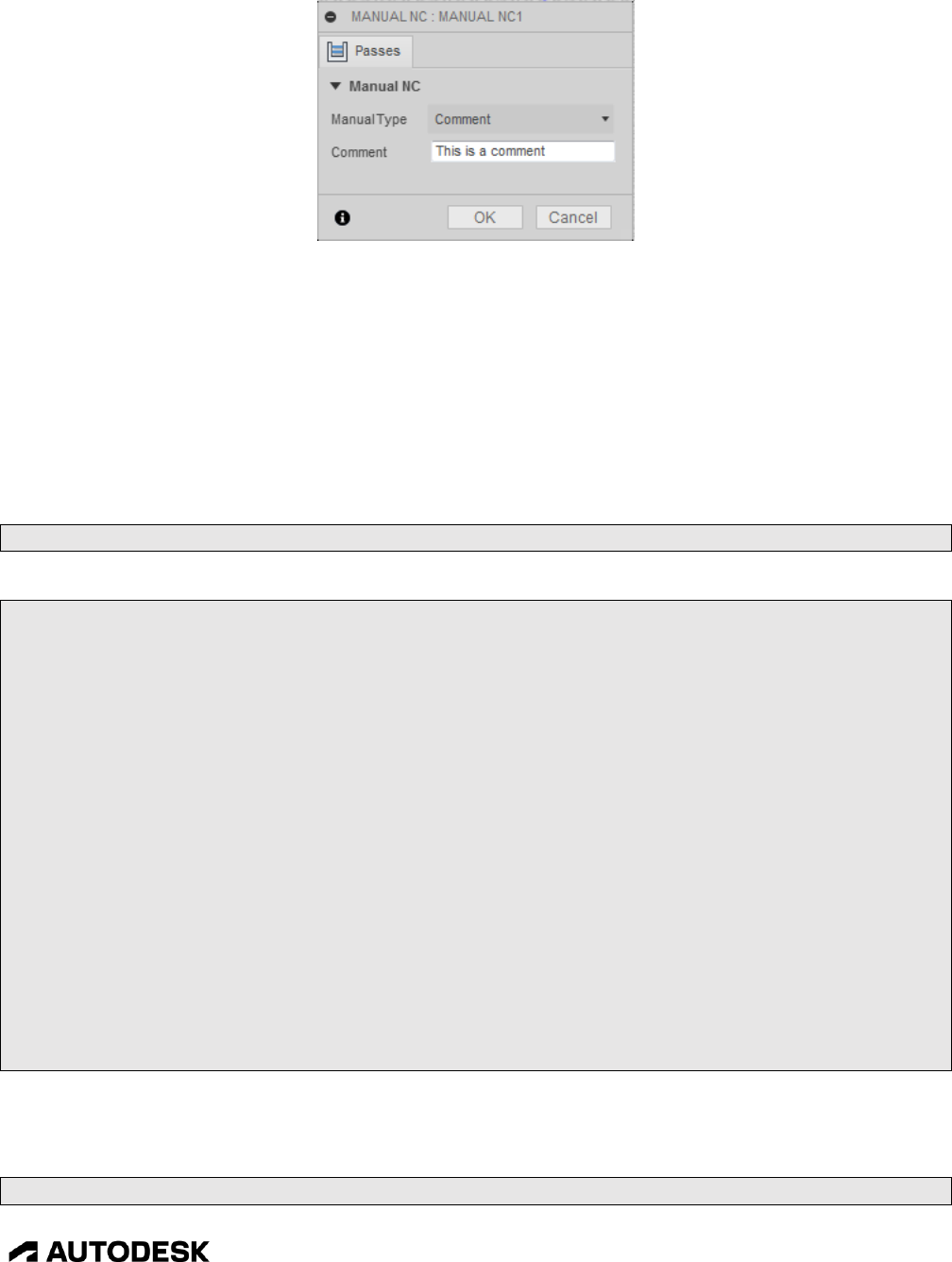
Entry Functions 5-158
CAM Post Processor Guide 2/2/24
The Comment Manual NC Command
There are two other functions that are used to format and output comments, formatComment and
writeComment. These comment functions are standard in nature and do not typically have to be
modified, though the permittedCommentChars variable, defined at the top of the post, is used to define
the characters that are allowed in a comment and may have to be changed to match the control. The
formatComment function will remove any characters in the comment that are not specified in this
variable. Lowercase letters will be converted to uppercase by the formatComment function. If you want
to support lowercase letters, then they would have to be added to the permittedCommentChars variable
and the formatComment function would need to have the conversion to uppercase removed.
var permittedCommentChars = " ABCDEFGHIJKLMNOPQRSTUVWXYZ0123456789.,=_-";
Defining the Permitted Characters for Comments
/** Format a comment */
function formatComment(text) {
return "(" + filterText(String(text).toUpperCase(), permittedCommentChars).replace(/[\(\)]/g, "") +
")";
}
/** Output a comment */
function writeComment(text) {
writeln(formatComment(text));
}
/** Process the Manual NC Comment command */
function onComment(message) {
var comments = String(message).split(";"); // allow multiple lines of comments per command
for (comment in comments) {
writeComment(comments[comment]);
}
}
The Comment Functions
5.10 onDwell
function onDwell(seconds) {

Entry Functions 5-159
CAM Post Processor Guide 2/2/24
Arguments
Description
seconds
Dwell time in seconds.
The onDwell function can be called by a Manual NC command, directly from HSM, or from the post
processor. The Manual NC command that calls onDwell is described in the Manual NC Commands
chapter. Internal calls to onDwell are usually generated when expanding a cycle. The post processor
itself will call onDwell directly to output a dwell block.
function onDwell(seconds) {
if (seconds > 99999.999) {
warning(localize("Dwelling time is out of range."));
}
milliseconds = clamp(1, seconds * 1000, 99999999);
writeBlock(gFeedModeModal.format(94), gFormat.format(4), "P" +
milliFormat.format(milliseconds));
}
Output the Dwell Time in Milliseconds
onCommand(COMMAND_COOLANT_ON);
onDwell(1.0); // dwell 1 second after turning coolant on
Calling onDwell Directly from Post Processor
5.11 onParameter
function onParameter(name, value) {
Arguments
Description
name
Parameter name.
value
Value stored in the parameter.
Almost all parameters used for creating a machining operation in HSM are passed to the post processor.
Common parameters are available using built in post processor variables (currentSection, tool, cycle,
etc.) as well as being made available as parameters. Other parameters are passed to the onParameter
function.
74: onParameter('operation:context', 'operation')
75: onParameter('operation:strategy', 'drill')
76: onParameter('operation:operation_description', 'Drill')
77: onParameter('operation:tool_type', 'tap right hand')
78: onParameter('operation:undercut', 0)
79: onParameter('operation:tool_isTurning', 0)
80: onParameter('operation:tool_isMill', 0)
81: onParameter('operation:tool_isDrill', 1)
82: onParameter('operation:tool_taperedType', 'tapered_bull_nose')

Entry Functions 5-160
CAM Post Processor Guide 2/2/24
83: onParameter('operation:tool_unit', 'inches')
84: onParameter('operation:tool_number', 4)
85: onParameter('operation:tool_diameterOffset', 4)
86: onParameter('operation:tool_lengthOffset', 4)
Sample Parameters Passed to the onParameter Function from Dump Post Processor
The name of the parameter along with its value is passed to the onParameter function. Some Manual
NC commands will call the onParameter function, these are described in the Manual NC Commands
chapter. You can see how to run and analyze the output from the dump.cps post processor in the
Debugging chapter.
function onParameter(name, value) {
switch (name) {
case "job-notes":
if (!firstNote) {
writeNotes(value, true);
}
firstNote = false;
break;
}
}
Sample onParameter Function
5.11.1 getParameter Function
value = getParameter(name [,default])
Arguments
Description
name
Parameter name.
default
The value to return if the requested parameter is not defined. If a default value
is not specified and the parameter is not defined, then undefined is returned.
You can retrieve operation parameters at any place in the post processor by calling the getParameter
function. Operation parameters are defined as parameters that are redefined for each machining
operation. There is a chance that a parameter does not exist so it is recommended that you check for the
parameter either by specifying a default value in the getParameter call or by using the hasParameter
function.
var comment = getParameter("operation-comment", ""); // get the parameter value
if (comment) {
writeComment(comment);
}
Verify a Parameter Exists Using the getParameter Function
if (hasParameter("operation-comment")) { // verify the parameter exists

Entry Functions 5-161
CAM Post Processor Guide 2/2/24
var comment = getParameter("operation-comment"); // get the parameter value
if (comment) {
writeComment(comment);
}
}
Verify a Parameter Exists Using the hasParameter Function
When scanning through the operations in the intermediate file it is possible to access the parameters for
that operation by using the section variant of the hasParameter and getParameter functions.
// write out all operation comments
writeln("List of Operations:");
for (var i = 0; i < getNumberOfSections(); ++i) {
var section = getSection(i);
var comment = section.getParameter("operation-comment", "");
if (comment) {
writeln(" " + comment);
}
}
writeln("");
Using Section Variant of getParameter
5.11.2 getGlobalParameter Function
value = getGlobalParameter(name [,default]))
Arguments
Description
name
Parameter name.
default
The value to return if the requested parameter is not defined. If a default value
is not specified and the parameter is not defined, then undefined is returned.
Some parameters are defined at the start of the intermediate file prior to the first operation. These
parameters are considered global and are accessed using the hasGlobalParameter and
getGlobalParameter functions. The same rules that apply to the operation parameters apply to global
parameters.
-1: onOpen()
0: onParameter('product-id', 'fusion360')
1: onParameter('generated-by', 'Fusion CAM 2.0.3803')
2: onParameter('generated-at', 'Saturday, March 24, 2018 4:34:36 PM')
3: onParameter('hostname', 'host')
4: onParameter('username', 'user')
5: onParameter('document-path', 'Water-Laser-Plasma v2')
6: onParameter('leads-supported', 1)
7: onParameter('job-description', 'Laser')

Entry Functions 5-162
CAM Post Processor Guide 2/2/24
9: onParameter('stock', '((0, 0, -5), (300, 200, 0))')
11: onParameter('stock-lower-x', 0)
13: onParameter('stock-lower-y', 0)
15: onParameter('stock-lower-z', -5)
17: onParameter('stock-upper-x', 300)
19: onParameter('stock-upper-y', 200)
21: onParameter('stock-upper-z', 0)
23: onParameter('part-lower-x', 0)
25: onParameter('part-lower-y', 0)
27: onParameter('part-lower-z', -5)
29: onParameter('part-upper-x', 300)
31: onParameter('part-upper-y', 200)
33: onParameter('part-upper-z', 0)
35: onParameter('notes', '')
Sample Global Variables
When processing multiple setups at the same time some of the global parameters will change from one
setup to the next. The getGlobalParameter function though will always reference the parameters of the
first setup, so if you want to access the parameters of the active setup then you will need to use the
onParameter function rather than the getGlobalParameter function.
function onParameter(name, value) {
if (name == "job-description") {
setupName = value;
}
}
Using onParameter to Store the Active Setup Name
5.12 onPassThrough
Function onPassThrough (value)
Arguments
Description
value
Text to be output to the NC file.
The onPassThrough function is called by the Pass through Manual NC command and is used to pass a
text string directly to the NC file without any processing by the post processor. This function is
described in the Manual NC Commands chapter.
5.13 onSpindleSpeed
function onSpindleSpeed(speed) {
Arguments
Description
spindleSpeed
The new spindle speed in RPM.

Entry Functions 5-163
CAM Post Processor Guide 2/2/24
The onSpindleSpeed function is used to output changes in the spindle speed during an operation,
typically from the post processor engine when expanding a cycle.
function onSpindleSpeed(spindleSpeed) {
writeBlock(sOutput.format(spindleSpeed));
}
Sample onSpindleSpeed Function
5.14 onOrientateSpindle
function onOrientateSpindle(angle) {
Arguments
Description
angle
Spindle orientation angle in radians.
The onOrientateSpindle function is not typically called. When a cycle that orientates the spindle is
expanded the onCommand(COMMAND_ORIENTATE_SPINDLE) function is called.
5.15 onRadiusCompensation
function onRadiusCompensation() {
The onRadiusCompensation function is called when the radius (cutter) compensation mode changes. It
will typically set the pending compensation mode, which will be handled in the motion functions
(onRapid, onLinear, onCircular, etc.). Radius compensation, when enabled in an operation, will be
enabled on the move approaching the part and disabled after moving off the part.
The state of radius compensation is stored in the global radiusCompensation variable and is not passed
to the onRadiusCompensation function. Radius compensation is defined when creating the machining
operation in HSM (1). The Sideways Compensation (2) setting determines the side of the part that the
tool will be on when cutting. It is based on the forward direction of the tool during the cutting operation.

Entry Functions 5-164
CAM Post Processor Guide 2/2/24
Enabling/Disabling Radius Compensation
Compensation Type
Description
In computer
The tool is offset from the part based on the tool diameter. The center
line of the offset tool is sent to the post processor and the radius
compensation mode is OFF (G40).
In control
The tool is not offset from the part. The centerline of the tool as if it is
on the part is sent to the post processor and the radius compensation
mode is determined by the Sideways Compensation setting (G41/G42).
The control will perform the entire offsetting of the tool.
Wear
The tool is offset from the part based on the tool diameter. The center
line of the offset tool is sent to the post processor and the radius
compensation mode is determined by the Sideways Compensation
setting (G41/G42). The control will compensate for tool wear.
Inverse wear
Same as Wear, but the opposite compensation direction will be used
(G42/G41).
Off
The tool is not offset from the part. The centerline of the tool as if it is
on the part is sent to the post processor and the radius compensation
mode will be disabled (G40).
Radius Compensation Modes
var pendingRadiusCompensation = -1;
function onRadiusCompensation() {
pendingRadiusCompensation = radiusCompensation;
}
Sample onRadiusCompensation Function
5.16 onMovement
function onMovement(movement) {

Entry Functions 5-165
CAM Post Processor Guide 2/2/24
Arguments
Description
movement
Movement type for the following motion(s).
onMovement is called whenever the movement type changes. It is used to tell the post when there is a
positioning, entry, exit, or cutting type move. There is also a movement global variable that contains the
movement setting. This variable can be referenced directly in other functions, such as onLinear, to
access the movement type without defining the onMovement function.
The supported movement types are listed in the following table.
Movement Type
Description
MOVEMENT_CUTTING
Standard cutting motion.
MOVEMENT_EXTENDED
Extended movement type. Not common.
MOVEMENT_FINISH_CUTTING
Finish cutting motion.
MOVEMENT_HIGH_FEED
Movement at high feedrate. Not typically used. Rapid moves
output using a linear move at the high feedrate will use the
MOVEMENT_RAPID type.
MOVEMENT_LEAD_IN
Lead-in motion.
MOVEMENT_LEAD_OUT
Lead-out motion.
MOVEMENT_LINK_DIRECT
Direction (non-cutting) linking move.
MOVEMENT_LINK_TRANSITION
Transition (cutting) linking move.
MOVEMENT_PLUNGE
Plunging move.
MOVEMENT_PREDRILL
Predrilling motion.
MOVEMENT_RAMP
Ramping entry motion.
MOVEMENT_RAMP_HELIX
Helical ramping motion.
MOVEMENT_RAMP_PROFILE
Profile ramping motion.
MOVEMENT_RAMP_ZIG_ZAG
Zig-Zag ramping motion.
MOVEMENT_RAPID
Rapid movement.
MOVEMENT_REDUCED
Reduced cutting motion.
Movement Types
Movement types are used in defining parametric feedrates in some milling posts and for removing all
non-cutting moves for waterjet/plasma/laser machines that require only the cutting profile.
5.17 onRapid
function onRapid(_x, _y, _z) {
Arguments
Description
_x, _y, _z
The tool position.
The onRapid function handles rapid positioning moves (G00) while in 3-axis mode. The tool position is
passed as the _x, _y, _z arguments. The format of the onRapid function is pretty basic, it will handle a
change in radius compensation, may determine if the rapid moves should be output at a high feedrate

Entry Functions 5-166
CAM Post Processor Guide 2/2/24
(due to the machine making dogleg moves while in rapid mode), and output the rapid move to the NC
file.
If the High feedrate mapping property is set to Always use high feed, then the onLinear function will be
called with the high feedrate passed in as the feedrate and the onRapid function will not be called.
Using High Feedrates for Positioning Moves
function onRapid(_x, _y, _z) {
// format tool position for output
var x = xOutput.format(_x);
var y = yOutput.format(_y);
var z = zOutput.format(_z);
// ignore if tool does not move
if (x || y || z) {
if (pendingRadiusCompensation >= 0) { // handle radius compensation
error(localize("Radius compensation mode cannot be changed at rapid traversal."));
return;
}
// output move at high feedrate if movement in more than one axis
if (!getProperty("useG0") && (((x ? 1 : 0) + (y ? 1 : 0) + (z ? 1 : 0)) > 1)) {
writeBlock(gFeedModeModal.format(94), gMotionModal.format(1), x, y, z,
getFeed(highFeedrate));
// output move in rapid mode
} else {
writeBlock(gMotionModal.format(0), x, y, z);
forceFeed();
}
}
}
Sample onRapid Function

Entry Functions 5-167
CAM Post Processor Guide 2/2/24
5.18 invokeOnRapid
invokeOnRapid(x, y, z);
Arguments
Description
x, y, z
The tool position.
It is possible that the post processor will need to generate rapid positioning moves during the processing
of the intermediate file. An example would be creating your own expanded drilling cycle. Instead of
calling onRapid with the post generated moves, it is recommended that invokeOnRapid be called
instead. This will ensure that the post engine is notified of the move and the current position is set.
invokeOnRapid will then call onRapid with the provided arguments.
5.19 onLinear
function onLinear(_x, _y, _z, feed) {
Arguments
Description
_x, _y, _z
The tool position.
feed
The feedrate.
The onLinear function handles linear moves (G01) at a feedrate while in 3-axis mode. The tool position
is passed as the _x, _y, _z arguments. The format of the onLinear function is pretty basic, it will handle
a change in radius compensation and outputs the linear move to the NC file.
function onLinear(_x, _y, _z, feed) {
// force move when radius compensation changes
if (pendingRadiusCompensation >= 0) {
xOutput.reset();
yOutput.reset();
}
// format tool position for output
var x = xOutput.format(_x);
var y = yOutput.format(_y);
var z = zOutput.format(_z);
var f = getFeed(feed);
// ignore if tool does not move
if (x || y || z) {
// handle radius compensation changes
if (pendingRadiusCompensation >= 0) {
pendingRadiusCompensation = -1;
var d = tool.diameterOffset;

Entry Functions 5-168
CAM Post Processor Guide 2/2/24
if (d > 200) {
warning(localize("The diameter offset exceeds the maximum value."));
}
writeBlock(gPlaneModal.format(17));
switch (radiusCompensation) {
case RADIUS_COMPENSATION_LEFT:
dOutput.reset();
writeBlock(gFeedModeModal.format(94), gMotionModal.format(1), gFormat.format(41), x, y, z,
dOutput.format(d), f);
break;
case RADIUS_COMPENSATION_RIGHT:
dOutput.reset();
writeBlock(gFeedModeModal.format(94), gMotionModal.format(1), gFormat.format(42), x, y, z,
dOutput.format(d), f);
break;
default:
writeBlock(gFeedModeModal.format(94), gMotionModal.format(1), gFormat.format(40), x, y, z,
f);
}
// output non-compensation change move at feedrate
} else {
writeBlock(gFeedModeModal.format(94), gMotionModal.format(1), x, y, z, f);
}
// no movement, but feedrate changes
} else if (f) {
if (getNextRecord().isMotion()) { // try not to output feed without motion
forceFeed(); // force feed on next line
} else {
writeBlock(gFeedModeModal.format(94), gMotionModal.format(1), f);
}
}
}
Sample onLinear Function
5.20 invokeOnLinear
invokeOnLinear(x, y, z, feed);
Arguments
Description
x, y, z
The tool position.
feed
The feedrate.
It is possible that the post processor will need to generate cutting moves during the processing of the
intermediate file. An example would be creating your own expanded drilling cycle. Instead of calling
onLinear with the post generated moves, it is recommended that invokeOnLinear be called instead. This

Entry Functions 5-169
CAM Post Processor Guide 2/2/24
will ensure that the post engine is notified of the move and the current position is set. invokeOnLinear
will then call onLinear with the provided arguments.
5.21 onRapid5D
function onRapid5D(_x, _y, _z, _a, _b, _c) {
Arguments
Description
_x, _y, _z
The tool position.
_a, _b, _c
The rotary angles if a machine configuration has been defined, otherwise the
tool axis vector is passed.
The onRapid5D function handles rapid positioning moves (G00) in multi-axis operations. The tool
position is passed as the _x, _y, _z arguments and the rotary angles as the _a, _b, _c arguments. If a
machine configuration has not been defined, then _a, _b, _c contains the tool axis vector. The
onRapid5D function will be called for all rapid moves in a multi-axis operation, even if the move is only
a 3-axis linear move without rotary movement.
Like the onRapid function, the onRapid5D function handles a change in radius compensation, may
determine if the rapid moves should be output at a high feedrate (due to the machine making dogleg
moves while in rapid mode), and outputs the rapid move to the NC file.
function onRapid5D(_x, _y, _z, _a, _b, _c) {
// enable this code if machine does not accept IJK tool axis vector input
if (false) {
if (!currentSection.isOptimizedForMachine()) {
error(localize("This post configuration has not been customized for 5-axis toolpath."));
return;
}
}
// handle radius compensation changes
if (pendingRadiusCompensation >= 0) {
error(localize("Radius compensation mode cannot be changed at rapid traversal."));
return;
}
// Machine Configuration has been defined, output rotary angles with move
if (currentSection.isOptimizedForMachine()) {
var x = xOutput.format(_x);
var y = yOutput.format(_y);
var z = zOutput.format(_z);
var a = aOutput.format(_a);
var b = bOutput.format(_b);
var c = cOutput.format(_c);

Entry Functions 5-170
CAM Post Processor Guide 2/2/24
writeBlock(gMotionModal.format(0), x, y, z, a, b, c);
// Machine Configuration has not been defined, output tool axis with move
} else {
forceXYZ();
var x = xOutput.format(_x);
var y = yOutput.format(_y);
var z = zOutput.format(_z);
var i = ijkFormat.format(_a);
var j = ijkFormat.format(_b);
var k = ijkFormat.format(_c);
writeBlock(gMotionModal.format(0), x, y, z, "I" + i, "J" + j, "K" + k);
}
forceFeed();
}
Sample onRapid5D Function
Please refer to the Multi-Axis Post Processors chapter for a detailed explanation on supporting a multi-
axis machine.
5.22 invokeOnRapid5D
invokeOnRapid5D(x, y, z, a, b, c);
Arguments
Description
x, y, z
The tool position.
a, b, c
The rotary angles if a machine configuration has been defined, otherwise the
tool axis vector is passed.
It is possible that the post processor will need to generate multi-axis rapid positioning moves during the
processing of the intermediate file. An example would be when handling the retract/reconfigure
procedure. Instead of calling onRapid5D with the post generated moves, it is recommended that
invokeOnRapid5D be called instead. This will ensure that the post engine is notified of the move and
the current position is set. invokeOnRapid5D will then call onRapid5D with the provided arguments.
5.23 onLinear5D
function onLinear5D(_x, _y, _z, _a, _b, _c, feed, feedMode) {
Arguments
Description
_x, _y, _z
The tool position.
_a, _b, _c
The rotary angles if a machine configuration has been defined, otherwise the
tool axis vector is passed.
feed
The feedrate value calculated for the multi-axis feedrate mode.
feedMode
The active multi-axis feedrate mode It can be FEED_FPM,
FEED_INVERSE_TIME, or FEED_DPM.

Entry Functions 5-171
CAM Post Processor Guide 2/2/24
The onLinear5D function handles cutting moves (G01) in multi-axis operations. The tool position is
passed as the _x, _y, _z arguments and the rotary angles as the _a, _b, _c arguments. If a machine
configuration has not been defined, then _a, _b, _c contains the tool axis vector. The onLinear5D
function will be called for all cutting moves in a multi-axis operation, even if the move is only a 3-axis
linear move without rotary movement.
It is important to know that the feedMode argument will not be present if multi-axis feedrates are not
defined either in an external Machine Definition or within the post processor using the
setMultiAxisFeedrate function. The feed value will always be passed as the programmed feedrate in this
case.
Like the onLinear function, the onLinear5D function handles a change in radius compensation, and
outputs the cutting move to the NC file.
function onLinear5D(_x, _y, _z, _a, _b, _c, feed, feedMode) {
// enable this code if machine does not accept IJK tool axis vector input
if (false) {
if (!currentSection.isOptimizedForMachine()) {
error(localize("This post configuration has not been customized for 5-axis toolpath."));
return;
}
}
// handle radius compensation changes
if (pendingRadiusCompensation >= 0) {
error(localize("Radius compensation cannot be activated/deactivated for 5-axis move."));
return;
}
// Machine Configuration has been defined, output rotary angles with move
if (currentSection.isOptimizedForMachine()) {
var x = xOutput.format(_x);
var y = yOutput.format(_y);
var z = zOutput.format(_z);
var a = aOutput.format(_a);
var b = bOutput.format(_b);
var c = cOutput.format(_c);
// get feedrate number
if (feedMode == FEED_INVERSE_TIME) {
feedOutput.reset();
}
var fMode = feedMode == FEED_INVERSE_TIME ? 93 : 94;
var f = feedMode == FEED_INVERSE_TIME ? inverseTimeOutput.format(feed) :
feedOutput.format(feed);

Entry Functions 5-172
CAM Post Processor Guide 2/2/24
// ignore if tool does not move
if (x || y || z || a || b || c) {
writeBlock(gFeedModeModal.format(fMode), gMotionModal.format(1), x, y, z, a, b, c, f);
} else if (f) {
if (getNextRecord().isMotion()) { // try not to output feed without motion
forceFeed(); // force feed on next line
} else {
writeBlock(gFeedModeModal.format(fMode), gMotionModal.format(1), f);
}
}
// Machine Configuration has not been defined, output tool axis with move
} else {
forceXYZ();
var x = xOutput.format(_x);
var y = yOutput.format(_y);
var z = zOutput.format(_z);
var i = ijkFormat.format(_a);
var j = ijkFormat.format(_b);
var k = ijkFormat.format(_c);
var f = getFeed(feed);
// ignore if tool does not move
if (x || y || z || i || j || k) {
writeBlock(gMotionModal.format(1), x, y, z, "I" + i, "J" + j, "K" + k, f);
} else if (f) {
if (getNextRecord().isMotion()) { // try not to output feed without motion
forceFeed(); // force feed on next line
} else {
writeBlock(gMotionModal.format(1), f);
}
}
}
}
Sample onLinear5D Function
Please refer to the Multi-Axis Post Processors chapter for a detailed explanation on supporting a multi-
axis machine.
5.24 invokeOnLinear5D
invokeOnLinear5D(x, y, z, a, b, c, feed);
Arguments
Description
x, y, z
The tool position.

Entry Functions 5-173
CAM Post Processor Guide 2/2/24
Arguments
Description
a, b, c
The rotary angles if a machine configuration has been defined, otherwise the
tool axis vector is passed.
feed
The feedrate.
It is possible that the post processor will need to generate multi-axis cutting moves during the processing
of the intermediate file. An example would be when handling the retract/reconfigure procedure. Instead
of calling onLinear5D with the post generated moves, it is recommended that invokeOnLinear5D be
called instead. This will ensure that the post engine is notified of the move and the current position is
set. invokeOnLinear5D will then call onLinear5D with the provided arguments.
The post engine will calculate the proper feedrate value and mode prior to calling onLinear5D.
5.25 onCircular
function onCircular(clockwise, cx, cy, cz, x, y, z, feed) {
Argument
Description
clockwise
Set to true if the circular direction is in the clockwise direction, false if
counter-clockwise.
cx, cy, cz
Center coordinates of circle.
x, y, z
Final point on circle
feed
The feedrate.
The onCircular function is called whenever there is circular, helical, or spiral motion. The circular
move can be in any of the 3 standard planes, XY-plane, YZ-plane, or ZX-plane, it is up to the
onCircular function to determine which types of circular interpolation are valid for the machine and to
correctly format the output.
The structure of the onCircular function in most posts uses the following layout.
1. Test for radius compensation. Most controls do not allow radius compensation to be started on a
circular move.
2. Full circle output.
3. Center point (IJK) output.
4. Radius output.
Each of the different styles of output will individually handle the output of circular interpolation in each
of the planes and possibly 3-D circular interpolation if it is supported.
if (pendingRadiusCompensation >= 0) { // Disallow radius compensation
error(localize("Radius compensation cannot be activated/deactivated for a circular move."));
return;
}
…

Entry Functions 5-174
CAM Post Processor Guide 2/2/24
if (isFullCircle()) { // Full 360 degree circles
if (getProperty("useRadius") || isHelical()) { // radius mode does not support full arcs
linearize(tolerance);
return;
}
…
} else if (!getProperty("useRadius")) { // Incremental center point output
switch (getCircularPlane()) {
case PLANE_XY:
…
} else { // Use radius mode
var r = getCircularRadius();
if (toDeg(getCircularSweep()) > (180 + 1e-9)) {
r = -r; // allow up to <360 deg arcs
}
…
Standard onCircular Structure
switch (getCircularPlane()) {
case PLANE_XY:
writeBlock(gPlaneModal.format(17), gMotionModal.format(clockwise ? 2 : 3),
xOutput.format(x), yOutput.format(y), zOutput.format(z),
iOutput.format(cx - start.x, 0), jOutput.format(cy - start.y, 0), getFeed(feed));
break;
case PLANE_ZX:
writeBlock(gPlaneModal.format(18), gMotionModal.format(clockwise ? 2 : 3),
xOutput.format(x), yOutput.format(y), zOutput.format(z),
iOutput.format(cx - start.x, 0), kOutput.format(cz - start.z, 0), getFeed(feed));
break;
case PLANE_YZ:
writeBlock(gPlaneModal.format(19), gMotionModal.format(clockwise ? 2 : 3),
xOutput.format(x), yOutput.format(y), zOutput.format(z),
jOutput.format(cy - start.y, 0), kOutput.format(cz - start.z, 0), getFeed(feed));
break;
default: // circular record is not in major plane
linearize(tolerance);
}
Circular Output Based on Plane
5.25.1 Circular Interpolation Settings
There are settings that affect how circular interpolation is handled in the post engine, basically telling
the post engine when to call onCircular or when to linearize the points by calling onLinear multiple
times instead. The following table describes the circular interpolation settings.

Entry Functions 5-175
CAM Post Processor Guide 2/2/24
Setting
Description
allowedCircularPlanes
Defines the standard planes that circular interpolation is allowed in,
PLANE_XY, PLANE_YZ, PLANE_ZX. It can be set to undefined to
allow circular interpolation in all three planes, 0 to disable circular
interpolation, or a bit mask of PLANE_XY, PLANE_YZ, and/or
PLANE_YZ to allow only certain planes.
allowHelicalMoves
Helical interpolation is allowed when this variable is set to true. Helical
moves are linearized if set to false.
allowSpiralMoves
Spiral interpolation is defined as circular moves that have a different
starting radius than ending radius and can be enabled by setting this
variable to true. Spiral moves are linearized if set to false.
circularInputTolerance
The tolerance to use when determining if a spiral or helical move should
be converted to a circular record. There are times when the CAM system
will output a circular record as a very small spiral or helical move, for
example a helix with a linear distance of 0.0001 over 180 degrees could be
programmed. Setting the circularInputTolerance variable to a nominal
value will convert any helical/spiral moves to a pure circular move when
the distance that marks the move as helical or spiral is less than this value.
A value of 0 will disable this feature.
circularMergeTolerance
The tolerance used to determine if consecutive circular records can be
merged into a single circular record. CAM systems will sometimes break
up a single circle into multiple circular records. Setting the
circulareMergeTolerance variable to a nominal value will combine
consecutive circular records into a single circular record whose centers and
radii are within this tolerance and the direction remains the same. A value
of 0 will disable this feature.
Circular moves will still be limited by the maximumCircularSweep value,
so if you wish to have 360-degree circular records you must define
maximumCircularSweep to be 360 degrees.
circularOutputAccuracy
Some controls are quite picky on the center/ending position of a circular
record and will fail if either of these are off by a single digit. Defining the
circularOutputAccuracy variable the same as the output number of digits
to the right of the decimal point for the linear axes will cause the post to
adjust the output center and/or ending positions so that they reflect the real
circle without any discrepancies. Leave undefined or use a value of 0 to
disable the adjustment of the center/final point.
Example: circularOutputAccuracy = unit == MM ? 3 : 4;
maximumCircularRadius
Specifies the maximum radius of circular moves that can be output as
circular interpolation and can be changed dynamically in the Property
table when running the post processor. Any circular records whose radius
exceeds this value will be linearized. This variable must be set in
millimeters (MM).

Entry Functions 5-176
CAM Post Processor Guide 2/2/24
Setting
Description
maximumCircularRadius = spatial(1000, MM); // 39.37 inch
maximumCircularSweep
Specifies the maximum angular sweep of circular moves that can be
output as circular interpolation and is specified in radians. Any circular
records whose delta angle exceeds this value will be linearized.
minimumChordLength
Specifies the minimum delta movement allowed for circular interpolation
and can be changed dynamically in the Property table when running the
post processor. Any circular records whose delta linear movement is less
than this value will be linearized. This variable must be set in millimeters
(MM).
minimumCircularRadius
Specifies the minimum radius of circular moves that can be output as
circular interpolation and can be changed dynamically in the Property
table when running the post processor. Any circular records whose radius
is less than this value will be linearized. This variable must be set in
millimeters (MM).
minimumCircularSweep
Specifies the minimum angular sweep of circular moves that can be output
as circular interpolation and is specified in radians. Any circular records
whose delta angle is less than this value will be linearized.
tolerance
Specifies the tolerance used to linearize circular moves that are expanded
into a series of linear moves. Circular interpolation records can be
linearized due to the conditions of the circular interpolation settings not
being met or by the linearize function being called. This variable must be
set in millimeters (MM).
Circular Interpolation Settings
allowedCircularPlanes = undefined; // allow all circular planes
allowedCircularPlanes = 0; // disable all circular planes
allowedCircularPlanes = (1 << PLANE_XY) | (1 << PLANE_ZX); // XY, ZX planes
tolerance = spatial(0.002, MM); // linearization tolerance of .00008 IN
minimumChordLength = spatial(0.01, MM); // minimum linear movement of .0004 IN
minimumCircularRadius = spatial(0.01, MM); // minimum circular radius of .0004 IN
maximumCircularRadius = spatial(1000, MM); // maximum circular radius of 39.37 IN
minimumCircularSweep = toRad(0.01); // minimum angular movement of .01 degrees
maximumCircularSweep = toRad(180); // circular interpolation up to 180 degrees
allowHelicalMoves = true; // enable helical interpolation
allowSpiralMoves = false; // disallow spiral interpolation
Example Circular Interpolation Settings
5.25.2 Circular Interpolation Common Functions/Variables
There are built-in functions that are utilized by the onCircular function. These functions return values
used in the onCircular function, determine if the circular record should be linearized, and control the

Entry Functions 5-177
CAM Post Processor Guide 2/2/24
flow of the onCircular function logic. Most circular functions have a corresponding variable that can be
referenced instead of calling the function.
var center = getCircularCenter(); // returns the circle center
var center = circularCenter; // references the circle center
Referencing the Circle Center Using Either a Function or Variable
Function
Variable
Description
getCircularArcLength()
circularArcLength
Returns the arc movement length of the
circular interpolation record.
getCircularCenter()
circularCenter
Returns the center point of the circle as a
Vector.
getCircularChordLength()
Returns the delta linear movement of the
circular interpolation record.
circularClockwise
Set to true if the circular move is in the
clockwise direction, false if it is in the
counter-clockwise direction.
getCircularNormal()
circularNormal
Returns the normal of the circular plane as a
Vector. The normal is flipped if the circular
movement is in the clockwise direction. This
follows the righthand plane convention.
getCircularOffset()
circularOffset
Returns the distances from the start point to
the circle plane in X, Y, and Z as a Vector.
getCircularPlane()
circularPlane
Returns the plane of the circular interpolation
record, PLANE_XY, PLANE_ZX, or
PLANE_YZ. If the return value is -1, then the
circular plane is not a major plane, but is in 3-
D space.
getCircularRadius()
circularRadius
Returns the end radius of the circular motion.
getCircularStartRadius()
circularStartRadius
Returns the start radius of the circular motion.
This will be different than the end radius for
spiral moves.
getCircularSweep()
circularSweep
Returns the angular sweep of the circular
interpolation record in radians.
getCurrentPosition()
Returns the starting point of the circular move
as a Vector.
getHelicalDistance()
circularHelicalDistance
Returns the distance the third axis will move
during helical interpolation. Returns 0 for a 2-
D circular interpolation record.
getHelicalOffset()
circularHelicalOffset
Returns the distance along the third axis as a
Vector. This function is used when helical
interpolation is supported outside one of the
three standard circular planes.

Entry Functions 5-178
CAM Post Processor Guide 2/2/24
Function
Variable
Description
getHelicalPitch()
circularHelicalPitch
Returns the distance that the third axis travels
for a full 360-degree sweep, i.e. the pitch
value of the thread.
getPositionU(u)
Returns the point on the circle at u percent
along the arc as a Vector.
isFullCircle()
circularFullCircle
Returns true if the angular sweep of the
circular motion is 360 degrees.
isHelical()
circularHelical
Returns true if the circular interpolation record
contains helical movement. The variable
allowHelicalMoves must be set to true for
helical records to be passed to the onCircular
function.
isSpiral()
circularSpiral
Returns true if the circular interpolation record
contains spiral movement (the start and end
radii are different). The variable
allowSpiralMoves must be set to true for spiral
records to be passed to the onCircular
function.
linearize(tolerance)
Linearizes the circular motion by outputting a
series of linear moves.
onCircular Common Functions
5.25.3 Helical Interpolation
Helical interpolation is defined as circular interpolation with movement along the third linear axis. The
third linear axis is defined as the axis that is not part of the circular plane, for example, the Z-axis is the
third linear axis for circular interpolation in the XY-plane. The variable allowHelicalMoves must be set
to true for the post processor to support helical interpolation.
Helical interpolation is typically output using the same format as circular interpolation with the addition
of the third axis and optionally a pitch value (incremental distance per 360 degrees) for the third axis.
Most stock post processors are already setup to output the third axis with circular interpolation (it won't
be output for a 2-D circular move).
case PLANE_XY:
writeBlock(gPlaneModal.format(17), gMotionModal.format(clockwise ? 2 : 3),
xOutput.format(x), yOutput.format(y), zOutput.format(z),
iOutput.format(cx-start.x, 0), jOutput.format(cy-start.y, 0), kOutput.format(getHelicalPitch()),
feedOutput.format(feed));
break;
Helical Interpolation with Pitch Output

Entry Functions 5-179
CAM Post Processor Guide 2/2/24
5.25.4 Spiral Interpolation
Spiral interpolation is defined as circular interpolation that has a different radius at start of the circular
move than the radius at the end of the move. The variable allowSpiralMoves must be set to true for the
post processor to support helical interpolation.
Spiral interpolation when supported on a control is typically specified with a G-code different than the
standard G02/G03 circular interpolation G-codes. Most stock post processors do not support spiral
interpolation.
if (isSpiral()) {
var startRadius = getCircularStartRadius();
var endRadius = getCircularRadius();
var dr = Math.abs(endRadius - startRadius);
if (dr > maximumCircularRadiiDifference) { // maximum limit
if (isHelical()) { // not supported
linearize(tolerance);
return;
}
switch (getCircularPlane()) {
case PLANE_XY:
writeBlock(gPlaneModal.format(17), gMotionModal.format(clockwise ? 2.1 : 3.1),
xOutput.format(x), yOutput.format(y), zOutput.format(z),
iOutput.format(cx - start.x, 0), jOutput.format(cy - start.y, 0), getFeed(feed));
break;
case PLANE_ZX:
writeBlock(gPlaneModal.format(18), gMotionModal.format(clockwise ? 2.1 : 3.1),
xOutput.format(x), yOutput.format(y), zOutput.format(z),
iOutput.format(cx - start.x, 0), kOutput.format(cz - start.z, 0), getFeed(feed));
break;
case PLANE_YZ:
writeBlock(gPlaneModal.format(19), gMotionModal.format(clockwise ? 2.1 : 3.1),
xOutput.format(x), yOutput.format(y), zOutput.format(z),
jOutput.format(cy - start.y, 0), kOutput.format(cz - start.z, 0), getFeed(feed));
break;
default:
linearize(tolerance);
}
return;
}
}
Spiral Interpolation Output

Entry Functions 5-180
CAM Post Processor Guide 2/2/24
5.25.5 3-D Circular Interpolation
3-D circular interpolation is defined as circular interpolation that is not on a standard circular plane (XY,
ZX, YZ).
3-D circular interpolation when supported on a control is typically specified with a G-code different than
the standard G02/G03 circular interpolation G-codes and must contain either the mid-point of the
circular move and/or the normal vector of the circle. Most stock post processors do not support 3-D
circular interpolation.
default:
if (getProperty("allow3DArcs")) { // a post property is used to enable support of 3-D circular
// make sure maximumCircularSweep is well below 360deg
var ip = getPositionU(0.5); // calculate mid-point of circle
writeBlock(gMotionModal.format(clockwise ? 2.4 : 3.4), // 3-D circular direction G-codes
xOutput.format(ip.x), yOutput.format(ip.y), zOutput.format(ip.z), // output mid-point of circle
getFeed(feed));
writeBlock(xOutput.format(x), yOutput.format(y), zOutput.format(z)); // output end-point
} else {
linearize(tolerance);
}
}
3-D Circular Interpolation Output
5.26 invokeOnCircular
invokeOnCircular(clockwise, cx, cy, cz, x, y, z, i, j, k, feed);
Arguments
Description
clockwise
Set to true if the direction of the circular is in the clockwise direction, false if it
is counter-clockwise.
cx, cy, cz
The center of the circle.
x, y, z
The tool position.
i, j, k
The normal vector of the circle.
feed
The feedrate.
It is possible that the post processor will need to generate circular arcs during the processing of the
intermediate file. To do this invokeOnCircular can be called. Calling invokeOnCircular ensures that
the post engine is notified of the arc move and the current position is set. invokeOnCircular will then
call onCircular with the provided arguments and setting the proper circular variables.
5.27 onCycle
function onCycle() {

Entry Functions 5-181
CAM Post Processor Guide 2/2/24
The onCycle function is called once at the beginning of an operation that contains a canned cycle and
can contain code to prepare the machine for the cycle. Mill post processors will typically set the
machining plane here.
function onCycle() {
writeBlock(gPlaneModal.format(17));
}
Sample onCycle Function
Mill/Turn post processors will usually handle the stock transfer sequence in the onCycle function. Logic
for the Mill/Turn post processors will be discussed in a dedicated chapter.
5.28 onCyclePoint
function onCyclePoint(x, y, z) {
Argument
Description
x, y, z
Hole bottom location.
Canned cycle output is handled in the onCyclePoint function, which includes positioning to the
clearance plane, formatting of the cycle block, calculating the cycle parameters, discerning if the canned
cycle is supported on the machine or should be expanded, and probing cycles which will not be
discussed in this chapter.
The location of the hole bottom for the cycle is passed in as the x, y, z arguments to the onCyclePoint
function. All other parameters are available in the cycle object or through cycle specific function calls.
The flow of outputting canned cycles usually follows the following logic.
1. First hole location in cycle
a. Position to clearance plane
b. Canned cycle is supported on machine
i. Calculate common cycle parameters
ii. Format and output canned cycle
c. Canned cycle is not supported on machine
i. Expand cycle into linear moves
2. 2
nd
through n
th
holes
a. Cycle is not expanded
i. Output hole location
b. Cycle is expanded
i. Expand cycle at new location
The actual output of the cycle blocks is handled in a switch block, with a separate case for each of the
supported cycles.
switch (cycleType) {
case "drilling":

Entry Functions 5-182
CAM Post Processor Guide 2/2/24
writeBlock(
gRetractModal.format(98), gAbsIncModal.format(90), gCycleModal.format(81),
getCommonCycle(x, y, z, cycle.retract),
feedOutput.format(F)
);
break;
Sample Cycle Formatting Code
If a cycle is not supported and needs to be expanded by the post engine, then you can either remove the
entire case block for this cycle and it will be handled in the default block, or you can specifically expand
the cycle. The second method is handy when the canned cycle does not support all of the parameters
available in HSM, for example if a dwell is not supported for a deep drilling cycle on the machine, but
you want to be able to use a dwell.
case "deep-drilling":
if (P > 0) { // the machine does not support a dwell code, so expand the cycle
expandCyclePoint(x, y, z);
} else {
writeBlock(
gRetractModal.format(98), gAbsIncModal.format(90), gCycleModal.format(83),
getCommonCycle(x, y, z, cycle.retract),
"Q" + xyzFormat.format(cycle.incrementalDepth),
feedOutput.format(F)
);
}
break;
Expanding a Cycle When a Feature is not Support on the Machine
The 2
nd
through the n
th
locations in a cycle operation are typically output using simple XY moves
without any of the cycle definition codes. Expanded cycles still need to be expanded at these locations.
} else { // end of isFirstCyclePoint() condition
if (cycleExpanded) {
expandCyclePoint(x, y, z);
} else {
var _x = xOutput.format(x);
var _y = yOutput.format(y);
if (!_x && !_y) {
xOutput.reset(); // at least one axis is required
_x = xOutput.format(x);
}
writeBlock(_x, _y);
}
}
Output the 2
nd
through n
th
Cycle Locations

Entry Functions 5-183
CAM Post Processor Guide 2/2/24
5.28.1 Drilling Cycle Types
The following table contains the drilling (hole making cycles). The cycle type is stored in the cycleType
variable as a text string. The standard G-code used for the cycle is included in the description, where
expanded defines the cycle as usually not being supported on the machine and expanded instead.
cycleType
Description
drilling
Feed in to depth and rapid out (G81)
counter-boring
Feed in to depth, dwell, and rapid out (G82)
chip-breaking
Multiple pecks with periodic partial retract to clear chips (G73)
deep-drilling
Peck drilling with full retraction at end of each peck (G83)
break-through-drilling
Allows for reduced speed and feed before breaking through hole
(expanded)
gun-drilling
Guided deep drilling allows for a change in spindle speed for
positioning (expanded)
tapping
Feed in to depth, reverse spindle, optional dwell, and feed out.
Automatically determines left or right tapping depending on the tool
selected. (G74/G84)
left-tapping
Left-handed tapping (G74)
right-tapping
Right-handed tapping (G84)
tapping-with-chip-breaking
Tapping with multiple pecks. Automatically determines left or right
tapping depending on the tool selected. (expanded)
reaming
Feed in to depth and feed out (G85)
boring
Feed in to depth, dwell, and feed out (G86)
stop-boring
Feed to depth, stop the spindle, and feed out (G87)
fine-boring
Feed to depth, orientate the spindle, shift from wall, and rapid out
(G76)
back-boring
Orientate the spindle, rapid to depth, start spindle, shift the tool to
wall, feed up to bore height, orientate spindle, shift from wall, and
rapid out (G77)
circular-pocket-milling
Mills out a hole (expanded)
thread-milling
Helical thread cutting (expanded)
Types of Drilling Cycles
Any of these cycles can be expanded if the machine control does not support the specific cycle. There
are some caveats, where the post (and machine) must support certain capabilities for the expanded cycle
to run correctly on the machine. The following table lists the commands that must be defined in the
onCommand function to support the expansion of these cycles. It is expected that the machine will
support these features if they are enabled in the post processor.
cycleType
Supported onCommand Command
tapping
left-tapping
right-tapping
tapping-with-chip-breaking
COMMAND_SPINDLE_CLOCKWISE
COMMAND_SPINDLE_COUNTERCLOCKWISE
COMMAND_ACTIVATE_SPEED_FEED_SYNCHRONIZATION
COMMAND_DEACTIVATE_SPEED_FEED_SYNCHRONIZATION
stop-boring
COMMAND_STOP_SPINDLE

Entry Functions 5-184
CAM Post Processor Guide 2/2/24
cycleType
Supported onCommand Command
COMMAND_START_SPINDLE
fine-boring
back-boring
COMMAND_STOP_SPINDLE
COMMAND_START_SPINDLE
COMMAND_ORIENTATE_SPINDLE
Required Command Support for Expanded Cycles
Certain cycles will use the following parameters when they are expanded.
machineParameters.
Description
drillingSafeDistance
Specifies the safety distance above the stock when repositioning into
the hole for the chip-breaking and deep-drilling cycles.
spindleOrientation
The spindle orientation angle after orientating the spindle.
spindleSpeedDwell
Dwell in seconds after the spindle speed changes during a cycle.
Parameters for Expanded Cycles
You define the expanded cycle parameters using the following syntaxes.
machineParameters.drillingSafeDistance = toPreciseUnit(2, MM);
machineParameters.spindleOrientation = 0;
machineParameters.spindleSpeedDwell = 1.5;
Defining Expanded Cycles Parameters
5.28.2 Cycle parameters
The parameters defined in the cycle operation are passed to the cycle functions using the cycle object.
The following variables are available and are referenced as 'cycle.parameter'.
Parameter
Description
accumulatedDepth
The depth of the combined cuts before the tool will be fully retracted
during a chip-breaking cycle.
backBoreDistance
The cutting distance of a back-boring cycle.
bottom
The bottom of the hole.
breakThroughDistance
The distance above the hole bottom to switch to the break-through
feedrate and spindle speed during a break-through-drilling cycle.
breakThroughFeedRate
The feedrate used when breaking through the hole during a break-
through-drilling cycle.
breakThroughSpindleSpeed
The spindle speed used when breaking through the hole during a
break-through-drilling cycle.
chipBreakDistance
The distance to retract the tool to break the chip during a chip-
breaking cycle.
clearance
Clearance plane where to tool will retract the tool to after drilling a
hole and position to the next hole.
compensation
Radius compensation in effect for circular-pocket-milling and thread-
milling cycles. This value can be control, wear, and inverseWear.

Entry Functions 5-185
CAM Post Processor Guide 2/2/24
Parameter
Description
compensationShiftOrientation
Same as shiftOrientation.
depth
The depth of the hole.
diameter
The diameter of the hole for circular-pocket-milling and thread-
milling cycles.
direction
Either climb or conventional milling for circular-pocket-milling and
thread-milling cycles.
dwell
The dwell time in seconds.
dwellDepth
The distance above the cut depth at which to dwell, used for gun-
drilling cycles.
feedrate
The primary cutting feedrate.
incrementalDepth
The incremental pecking depth of the first cut.
incrementalDepthReduction
The incremental pecking depth reduction per cut for pecking cycles.
minimumIncrementalDepth
The minimum pecking depth of cut for pecking cycles.
numberOfSteps
The number of horizontal passes for the thread-milling cycle.
plungeFeedrate
The cutting feedrate. The same as feedrate.
plungesPerRetract
The number of cuts before the tool will be fully retracted during a
chip-breaking cycle.
postioningFeedrate
The feedrate used to position the tool during a gun-drilling cycle.
positioningSpindleSpeed
The spindle speed used when positioning the tool during a gun-
drilling cycle.
repeatPass
Set to true if the final pass should be repeated for circular-pocket-
milling and thread-milling cycles.
retract
The plane where the tool will position to prior to starting the cycle
(feeding into the hole).
retractFeedrate
The tool retraction feedrate, used when feeding out of the hole.
shift
The distance to shift the tool away from the wall during a fine-boring
and back-boring cycle.
shiftDirection
The direction in radians to shift the tool away from the wall during a
fine-boring and back-boring cycle. The shift direction will be PI
radians (180 degrees) from the wall plus this amount.
shiftOrientation
The spindle orientation of the tool in radians when shifting the tool
away from the wall during a fine-boring or back-boring cycle.
stepover
The horizontal stepover distance for circular-pocket-milling and
thread-milling cycles.
stock
The top of the hole.
stopSpindle
When set to 1, the spindle will be stopped during
positioning/retracting in a gun-drilling cycle.
threading
Either right or left-handed threading for thread-milling cycles.
Cycle Parameters
5.28.3 The Cycle Planes/Heights
The drilling cycles use different heights during the execution of the cycle. These heights are specified in
the Heights tab for the Drilling operation. One thing you should keep in mind is that the names given to

Entry Functions 5-186
CAM Post Processor Guide 2/2/24
these heights do not match the cycle parameter names in the post processor. The following table gives
the relationship between the HSM height names and the equivalent cycle parameter names.
Operation Heights Tab
Cycle Parameter
Description
Clearance Height
(none)
The plane to position to the
first point of the cycle and to
retract the tool to after the
final point of the cycle.
Retract Height
cycle.clearance
The tool rapids to this plane
from the clearance height
and will position between the
holes at this height.
Feed Height
cycle.retract
The tool will feed from this
plane into the hole.
Top Height
cycle.stock
The top of the hole.
Bottom Height
cycle.bottom
The bottom of the hole. This
height is the plane where the
tool will drill to and will be
different from the actual
bottom of the hole if the
Drill tip through bottom box
is checked.
Correlation Between Cycle Operation Heights and Cycle Parameters
HSM assumes that the tool will always be retracted to the Retract Height (cycle.clearance) between
holes, you will notice this in the simulation of the cycle in HSM. This is typically handled in the
machine control with a G98 (Retract to clearance plane) code. Of course this code can be different from
machine control to machine control and there are controls that will always retract to the Feed Height
(cycle.retract) at the end of a drilling operation. In this case it is up to the post processor to retract the
tool to the Retract Height.
You can cancel the cycle at the end of the onCyclePoint function and output a tool retract block to take
the tool back up to the Retract Height. When this method is used it is also mandatory that the full cycle
be output for every hole in the operation and not just the first cycle point. Some machines support a
retract plane to be specified with the cancel cycle code, i.e. G80 Rxxx.
function onCyclePoint(x, y, z) {
// if (isFirstCyclePoint()) {
if (true) { // output a full cycle block for every hole in the operation
repositionToCycleClearance(cycle, x, y, z);
...
...
default:
expandCyclePoint(x, y, z);
}
// retract tool (add at the end of the cycleType switch code)

Entry Functions 5-187
CAM Post Processor Guide 2/2/24
gMotionModal.format.reset();
writeBlock(gCycleModal.format(80), gMotionModal.format(0), zOutput.format(cycle.clearance));
} else {
if (cycleExpanded) {
Retracting the Tool to the Retract Plane when Unsupported by Machine Control
5.28.4 Common Cycle Functions
There are functions that are commonly used in the onCyclePoint function. The following table lists
these functions.
Function
Description
isFirstCyclePoint()
Returns true if this is the first point in the cycle operation. It is
usually called to determine whether to output a full cycle block or
just the cycle location.
isLastCyclePoint()
Returns true if this is the last point in the cycle operation. This
function is typically used for a lathe threading operation since
HSM sends a single pass to the onCyclePoint function and the full
depth of the thread is required to output a single threading block.
onCycleEnd is used to terminate a drilling cycle, so this function is
not typically used in drilling cycles.
isProbingCycle()
Returns true if this is a probing cycle.
repositionToCycleClearance()
Moves the tool to the Retract Height plane (cycle.clearance). This
function is typically called prior to outputting a full cycle block.
getCommonCycle(x, y, z, r)
Formats the common cycle parameters (X, Y, Z, R) for output.
Common Cycle Functions
These functions are built into the post engine, except the getCommonCycle function, which is contained
in the post processor. It takes the cycle location (x, y, z) and the retract plane/distance (r) as arguments.
Some machines require that the retract value be programmed as a distance from the current location
rather than as an absolute position. There are two ways to accomplish this. You can pass in the distance
as the retract value.
function getCommonCycle(x, y, z, r) {
forceXYZ();
return [xOutput.format(x), yOutput.format(y),
zOutput.format(z),
"R" + xyzFormat.format(r)];
}
…
case "drilling":
writeBlock(
gRetractModal.format(98), gAbsIncModal.format(90), gCycleModal.format(81),
getCommonCycle(x, y, z, cycle.retract – cycle.clearance),
feedOutput.format(F)

Entry Functions 5-188
CAM Post Processor Guide 2/2/24
);
break;
Pass Retract Distance to Standard getCommonCycle Function
Or you can pass the clearance plane in to the getCommonCycle function and have it calculate the
distance. This method is typically used in post processors that support subprograms that require a retract
plane while in absolute mode and a distance when in incremental mode.
function getCommonCycle(x, y, z, r, c) {
forceXYZ(); // force xyz on first drill hole of any cycle
if (incrementalMode) {
zOutput.format(c);
return [xOutput.format(x), yOutput.format(y),
"Z" + xyzFormat.format(z - r),
"R" + xyzFormat.format(r - c)];
} else {
return [xOutput.format(x), yOutput.format(y),
zOutput.format(z),
"R" + xyzFormat.format(r)];
}
}
…
case "drilling":
writeBlock(
gRetractModal.format(98), gCycleModal.format(81),
getCommonCycle(x, y, z, cycle.retract, cycle.clearance),
feedOutput.format(F)
);
break;
Pass Retract and Clearance Heights to getCommonCycle Function
5.28.5 Feed per Revolution Output with Drilling Cycles
It is possible to support feed per revolution (FPR) feedrates with drilling cycles. FPR feedrates can be
selected in the Drill operation by enabling the Use Feed per Revolution checkbox.
Specify that Feed per Revolution Feedrates are to be used with Drilling Cycles

Entry Functions 5-189
CAM Post Processor Guide 2/2/24
The post must inform the CAM system that FPR feedrates are supported and have logic in the post to
output the proper codes for FPR feedrates. Setting the allowFeedPerRevolutionDrilling variable to true
enables FPR feedrates in the post. If this variable is set to false, then drilling cycles that select FPR
feedrates will be output in feed per minute (FPM) mode.
allowFeedPerRevolutionDrilling = true; // Enable FPR feedrates for drilling cycles
Enable FPR Feedrates for Drilling Cycles
A formatNumber must be defined to format FPR feedrate numbers. The format is defined at the top of
the post processor with the rest of the format definitions. Refer to the Format Defintions section.
var feedPerRevFormat = createFormat({decimals:(unit == MM ? 3 : 4), forceDecimal:true});
Create Output Format for FPR Feedrates
The feedrate mode for the operation should be checked in the onSection function, the appropriate output
format assigned, and the code to enable the feedrate mode output.
// Output modal commands here
var fMode;
if (currentSection.feedMode == FEED_PER_REVOLUTION) { // FPR feedrates
feedOutput.setFormat(feedPerRevFormat);
fMode = 95;
} else { // FPM feedrates
feedOutput.setFormat(feedFormat);
fMode = 94;
}
writeBlock(gPlaneModal.format(17), gAbsIncModal.format(90), gFeedModeModal.format(fMode));
Define the Feedrate Output Format and Output the Feedrate Mode Code
Your post should now support FPR feedrates for drilling cycles.
5.28.6 Pitch Output with Tapping Cycles
Tapping cycles can sometimes be output with a standard FPM feedrate, sometimes with a thread pitch,
and sometimes using the FPR feedrate mode. There are different variables and formats involved
depending on the format used. When using pitch or FPR feedrates you will need to create a format for
this style of feedrate. The format is defined at the top of the post processor with the rest of the format
definitions. Refer to the Format Defintions and Output Variable Definitions sections.
var feedFormat = createFormat({decimals:(unit == MM ? 0 : 1), forceDecimal:true});
var pitchFormat = createFormat({decimals:(unit == MM ? 3 : 4), forceDecimal:true});
…
var feedOutput = createVariable({prefix:"F"}, feedFormat);
var pitchOutput = createVariable({prefix:"F", force:true}, pitchFormat);
Create the Pitch Output Format

Entry Functions 5-190
CAM Post Processor Guide 2/2/24
In the tapping sections of the onCyclePoint function you will need to assign the correct pitch value to the
output. The tapping pitch is stored in the tool.threadPitch variable.
case "tapping":
writeBlock(
gRetractModal.format(98), gCycleModal.format((84),
getCommonCycle(x, y, z, cycle.retract),
(conditional(P > 0, "P" + milliFormat.format(P)),
pitchOutput.format(tool.threadPitch)
);
forceFeed(); // force the feedrate to be output after a tapping cycle with pitch output
break;
Output the Thread Pitch on a Tapping Cycle
If the tapping cycle requires that the machine be placed in FPR mode, then you can also calculate the
pitch value by dividing the feedrate by the spindle speed. You will also need to output the FPR code
(G95) with the tapping cycle and reset it at the end of the tapping operation, usually in the onCycleEnd
function.
case "tapping":
var F = cycle.feedrate / spindleSpeed;
writeBlock(
gRetractModal.format(98), gFeedModeModal.format(95), gCycleModal.format((84),
getCommonCycle(x, y, z, cycle.retract),
(conditional(P > 0, "P" + milliFormat.format(P)),
pitchOutput.format(F)
);
forceFeed(); // force the feedrate to be output after a tapping cycle with pitch output
break;
Output the Feedrate as FPR on a Tapping Cycle
5.29 onCycleEnd
function onCycleEnd() {
The onCycleEnd function is called after all points in the cycle operation have been processed. The cycle
is cancelled in this function and the feedrate mode (FPM) is reset if it is a tapping operation that uses
FPR feedrates.
function onCycleEnd() {
if (!cycleExpanded) {
writeBlock(gCycleModal.format(80));
// writeBlock(gFeedModeModal.format(94)), gCycleModal.format(80)); // reset FPM mode
zOutput.reset();
}

Entry Functions 5-191
CAM Post Processor Guide 2/2/24
}
onCycleEnd Function
5.30 Common Functions
There are functions that are common in most of the generic posts. Some of these functions are used in
conjuction with other post processor functions and are described in the appropriate section of this
manual, for example the formatComment function is described with the onComment function. This
section describes the common functions that are generic in nature and used throughout the post
processor.
5.30.1 writeln
writeln(text);
Arguments
Description
text
Text to output to the NC file
The writeln function is built into the post engine and is not defined in the post processor. It is used to
output text to the NC file without formatting it. Text can be a quoted text string or a text expression.
writeln is typically used for outputting text strings that don't require formatting, or debug messages.
writeln("%"); // outputs '%'
writeln("Vector = " + new Vector(x, y, z)); // outputs the x, y, z variables in vector format
writeln(""); // outputs a blank line
writeln(formatComment("Load tool " + tool.number + " in spindle");
// outputs 'Load tool n in spindle' as a comment
Sample writeln Calls
5.30.2 writeBlock
function writeBlock(arguments) {
Arguments
Description
arguments
Comma separated list of codes/text to output.
The writeBlock function writes a block of codes to the output NC file. It will add a sequence number to
the block, if sequence numbers are enabled and add an optional skip character if this is an optional
operation. A list of formatted codes and/or text strings are passed to the writeBlock function. The code
list is separated by commas, so that each code is passed as an individual argument, which allows for the
codes to be separated by the word separator defined by the setWordSeparator function.
/**
Writes the specified block.
*/

Entry Functions 5-192
CAM Post Processor Guide 2/2/24
function writeBlock() {
var text = formatWords(arguments);
if (!text) {
return;
}
if (getProperty("showSequenceNumbers")) { // add sequence numbers to output blocks
if (optionalSection) {
if (text) {
writeWords("/", "N" + sequenceNumber, text);
}
} else {
writeWords2("N" + sequenceNumber, text);
}
sequenceNumber += getProperty("sequenceNumberIncrement");
} else { // no sequence numbers
if (optionalSection) {
writeWords2("/", text);
} else {
writeWords(text);
}
}
}
Sample writeBlock Function
writeBlock(gAbsIncModal.format(90), xFormat.format(x), yFormat.format(y));
writeBlock("G28", "X" + xFormat.format(0), "Y" + yFormat.format(0)); // outputs 'G28 X0 Y0'
writeBlock("G28" + "X" + xFormat.format(0) + "Y" + yFormat.format(0)); // outputs 'G28 X0Y0'
Sample writeBlock Calls
The writeBlock function does not usually have to be modified.
5.30.3 toPreciseUnit
toPreciseUnit(value, units);
Arguments
Description
value
The input value.
units
The units that the value is given in, either MM or IN.
The toPreciseUnit function allows you to specify a value in a given units and that value will be returned
in the active units of the input intermediate CNC file. When developing a post processor, it is highly
recommended that any unit based hard coded numbers use the toPreciseUnit function when defining the
number.

Entry Functions 5-193
CAM Post Processor Guide 2/2/24
yAxisMinimum = toPreciseUnit(gotYAxis ? -50.8 : 0, MM); // minimum range for the Y-axis
yAxisMaximum = toPreciseUnit(gotYAxis ? 50.8 : 0, MM); // maximum range for the Y-axis
xAxisMinimum = toPreciseUnit(0, MM); // maximum range for the X-axis (radius mode)
Defining Values using toPreciseUnit
5.30.4 force---
The force functions are used to force the output of the specified axes and/or feedrate the next time they
are supposed to be output, even if it has the same value as the previous value.
Function
Description
forceXYZ
Forces the output of the linear axes (X, Y, Z) on the next motion block.
forceABC
Forces the output of the rotary axes (A, B, C) on the next motion block.
forceFeed
Forces the output of the feedrate on the next motion block.
forceAny
Forces all axes and the feedrate on the next motion block.
Force Functions
/** Force output of X, Y, and Z on next output. */
function forceXYZ() {
xOutput.reset();
yOutput.reset();
zOutput.reset();
}
/** Force output of A, B, and C on next output. */
function forceABC() {
aOutput.reset();
bOutput.reset();
cOutput.reset();
}
/** Force output of F on next output. */
function forceFeed() {
currentFeedId = undefined;
feedOutput.reset();
}
/** Force output of X, Y, Z, A, B, C, and F on next output. */
function forceAny() {
forceXYZ();
forceABC();
forceFeed();
}
Sample Force Functions

Entry Functions 5-194
CAM Post Processor Guide 2/2/24
5.30.5 writeRetract
function writeRetract(arguments) {
Arguments
Description
arguments
X, Y, and/or Z. Separated by commas when multiple axes are specified.
The writeRetract function is used to retract the Z-axis to its clearance plane and move the X and Y axes
to their home positions.
The writeRetract function can be called with one or more axes to move to their home position. The axes
are specified using their standard names of X, Y, Z, and are separated by commas if multiple axes are
specified in the call to writeRetract.
writeRetract(Z); // move the Z-axis to its home position
writeRetract(X, Y); // move the X and Y axes to their home positions
Sample writeRetract Calls
The writeRetract function is not generic in nature and may have to be changed to match your machine's
requirements. For example, some machines use a G28 to move an axis to its home position, some will
use a G53 with the home position, and some use a standard G00 block.
/** Output block to do safe retract and/or move to home position. */
function writeRetract() {
// initialize routine
var _xyzMoved = new Array(false, false, false);
var _useG28 = getProperty("useG28"); // can be either true or false
// check syntax of call
if (arguments.length == 0) {
error(localize("No axis specified for writeRetract()."));
return;
}
for (var i = 0; i < arguments.length; ++i) {
if ((arguments[i] < 0) || (arguments[i] > 2)) {
error(localize("Bad axis specified for writeRetract()."));
return;
}
if (_xyzMoved[arguments[i]]) {
error(localize("Cannot retract the same axis twice in one line"));
return;
}
_xyzMoved[arguments[i]] = true;
}
// special conditions

Entry Functions 5-195
CAM Post Processor Guide 2/2/24
if (_useG28 && _xyzMoved[2] && (_xyzMoved[0] || _xyzMoved[1])) { // XY don't use G28
error(localize("You cannot move home in XY & Z in the same block."));
return;
}
if (_xyzMoved[0] || _xyzMoved[1]) {
_useG28 = false;
}
// define home positions
var _xHome;
var _yHome;
var _zHome;
if (_useG28) {
_xHome = 0;
_yHome = 0;
_zHome = 0;
} else {
if (getProperty("homePositionCenter") &&
hasParameter("part-upper-x") && hasParameter("part-lower-x")) {
_xHome = (getParameter("part-upper-x") + getParameter("part-lower-x")) / 2;
} else {
_xHome = machineConfiguration.hasHomePositionX() ?
machineConfiguration.getHomePositionX() : 0;
}
_yHome = machineConfiguration.hasHomePositionY() ?
machineConfiguration.getHomePositionY() : 0;
_zHome = machineConfiguration.getRetractPlane();
}
// format home positions
var words = []; // store all retracted axes in an array
for (var i = 0; i < arguments.length; ++i) {
// define the axes to move
switch (arguments[i]) {
case X:
// special conditions
if (getProperty("homePositionCenter")) { // output X in standard block by itself if centering
writeBlock(gMotionModal.format(0), xOutput.format(_xHome));
_xyzMoved[0] = false;
break;
}
words.push("X" + xyzFormat.format(_xHome));
break;
case Y:
words.push("Y" + xyzFormat.format(_yHome));
break;

Manual NC Commands 6-196
CAM Post Processor Guide 2/2/24
case Z:
words.push("Z" + xyzFormat.format(_zHome));
retracted = true;
break;
}
}
// output move to home
if (words.length > 0) {
if (_useG28) { // use G28 to move to home position
gAbsIncModal.reset();
writeBlock(gFormat.format(28), gAbsIncModal.format(91), words);
writeBlock(gAbsIncModal.format(90));
} else { // use G53 to move to home position
gMotionModal.reset();
writeBlock(gAbsIncModal.format(90), gFormat.format(53), gMotionModal.format(0), words);
}
// force any axes that move to home on next block
if (_xyzMoved[0]) {
xOutput.reset();
}
if (_xyzMoved[1]) {
yOutput.reset();
}
if (_xyzMoved[2]) {
zOutput.reset();
}
}
}
Sample writeRetract Function
6 Manual NC Commands
Manual NC commands are used to control the behavior of individual operations when there is not a
setting in the operation form for controlling a specific feature of a control. You can use Manual NC
commands to display a message, insert codes into the output NC file, perform an optional stop, define a
setting, etc. The Manual NC menu is accessed from different areas of the ribbon menu depending on the
product you are running.

Manual NC Commands 6-197
CAM Post Processor Guide 2/2/24
Selecting a Manual NC Command in the HSM Products (Fusion, Inventor, HSMWorks)
Once you select the Manual NC menu you will see a form displayed that is used to select the type of
Manual NC command that you want to pass to the post processor and optionally the parameter that will
be passed with the command.
Defining a Manual NC Command
If you use a Manual NC command in your part, then it is necessary that the post processor is equipped to
handle this command. Some of the commands are supported by the stock post processors, such as Stop,
Optional stop, and Dwell, while support would have to be added to the post processor to support other
Manual NC commands. If you use a Manual NC command that is not supported by the post, then it will
either generate an error or be ignored. The general rule is it will generate an error if the onCommand
function is called and will be ignored when another function is called.
6.1 onManualNC and expandManualNC
function onManualNC(command, value) {
expandManualNC(command, value)
Arguments
Description
command
The Manual NC command that invoked the function.
value
The value entered with the command.

Manual NC Commands 6-198
CAM Post Processor Guide 2/2/24
The onManualNC function is defined in the post processor and is used to process Manual NC
commands. It accepts the command and the value that is assigned to the command. If the onManualNC
function is not defined in the post processor, then a separate function will be called as listed in the table
below.
The expandManualNC command can also be used to process the Manual NC command using the
separate functions listed in the table. It is typically used as the default condition in the onManualNC
function to process commands where you do not care if they are entered as a Manual NC command or
from an internal call in the post processor.
The following table describes the Manual NC commands along with the function that will be called
when the command is processed when the onManualNC function does not exist or expandManualNC is
called.
Manual NC
Command
Description
Command
Value
Function Called
Comment
Operator message
COMMAND_COMMENT
message
onComment
Stop
Machine stop
COMMAND_STOP
onCommand
Optional
Stop
Optional stop
COMMAND_OPTIONAL_STOP
onCommand
Dwell
Dwell
COMMAND_DWELL
Dwell time
in seconds
onDwell
Tool break
control
Check for tool
breakage
COMMAND_BREAK_CONTROL
onCommand
Measure tool
Automatically
measure tool
length
COMMAND_TOOL_MEASURE
onCommand
Start chip
transport
Start chip
conveyor
COMMAND_START_CHIP_TRANSPORT
onCommand
Stop chip
transport
Stop chip
conveyor
COMMAND_STOP_CHIP_TRANSPORT
onCommand
Open door
Open main door
COMMAND_OPEN_DOOR
onCommand
Close door
Close main door
COMMAND_CLOSE_DOOR
onCommand
Calibrate
Calibration of
machine
COMMAND_CALIBRATE
onCommand
Verify
Verify integrity of
machine
COMMAND_VERIFY
onCommand
Clean
Request a cleaning
cycle
COMMAND_CLEAN
onCommand
Action
User defined
action
COMMAND_ACTION
text
onParameter
Print
message
Print a message
from the machine
COMMAND_PRINT_MESSAGE
message
onParameter
Display
message
Display operator
message
COMMAND_DISPLAY_MESSAGE
message
onParameter

Manual NC Commands 6-199
CAM Post Processor Guide 2/2/24
Manual NC
Command
Description
Command
Value
Function Called
Alarm
Create an alarm on
the machine
COMMAND_ALARM
onCommand
Alert
Request an alert
event on the
machine
COMMAND_ALERT
onCommand
Pass through
Output literal text
to NC file
COMMAND_PASS_THROUGH
text
onPassThrough
Force tool
change
Force a tool
change
section.getForceToolChange()
(none)
Call program
Call a subprogram
COMMAND_CALL_PROGRAM
text
onParameter
Manual NC Commands
6.1.1 Sample onManualNC Function
The onManualNC function is a recent addition to the post processor and will not be found in most
generic post processors. You do not have to define it to process Manual NC commands, and if it is
defined, do not need to process all Manual NC commands in this function. It could be used to process
only the commands where you need to know if they were generated from a CAM Manual NC command
instead of a direct call from within the post processor.
For example, the following onManualNC function definition could be used to process comments entered
using the CAM Manual NC command differently than comments generated from the post processor. It
simply appends the text ‘MSG,’ prior to the comment for a Manual NC Display comment command. All
other Manual NC commands are processed normally.
function onManualNC(command, value) {
switch (command) {
case COMMAND_DISPLAY_MESSAGE:
writeComment("MSG, " + value);
break;
default:
expandManualNC(command, value); // normal processing of Manual NC command
}
}
Handling of Display Message Command in onManualNC
6.1.2 Delay Processing of Manual NC Commands
Manual NC commands are processed at the placement in the operation tree where they are entered,
which means that they will be processed prior to the call to onSection. Since onSection typically
terminates the previous operation prior to starting the new operation, this might not be the desirable
location to process the Manual NC command.

Manual NC Commands 6-200
CAM Post Processor Guide 2/2/24
The following code examples show how Manual NC commands can be buffered and output at any point
during the operation. You can simply copy the onManualNC and executeManualNC functions into your
post processor and add the appropriate call(s) to executeManualNC where you want to process the
Manual NC commands.
/**
Buffer Manual NC commands for processing later
*/
var manualNC = [];
function onManualNC(command, value) {
manualNC.push({command:command, value:value});
}
/**
Processes the Manual NC commands
Pass the desired command to process or leave argument list blank to process all buffered
commands
*/
function executeManualNC(command) {
for (var i = 0; i < manualNC.length; ++i) {
if (!command || (command == manualNC[i].command)) {
switch(manualNC[i].command) {
case COMMAND_DISPLAY_MESSAGE:
writeComment("MSG, " + manualNC[i].value);
break;
default:
expandManualNC(manualNC[i].command, manualNC[i].value);
}
}
}
for (var i = manualNC.length -1; i >= 0; --i) {
if (!command || (command == manualNC[i].command)) {
manualNC.splice(i, 1);
}
}
}
Manual NC Commands Support Functions
The calls to process the Manual NC commands can be placed anywhere in the post processor. In the
following code example, the COMMAND_DISPLAY_MESSAGE command is processed just before
the tool change block is output and the rest of the Manual NC commands after the tool change block.
executeManualNC(COMMAND_DISPLAY_MESSAGE); // display Manual NC message
writeBlock("T" + toolFormat.format(tool.number), mFormat.format(6));
if (tool.comment) {
writeComment(tool.comment);

Manual NC Commands 6-201
CAM Post Processor Guide 2/2/24
}
executeManualNC(); // process remaining Manual NC commands
Processing of Manual NC Commands in the Desired Location
The following sections give a description of the functions that are called by the Manual NC commands
outside of the onManualNC function and samples on how they are handled in the functions. The
onComment and onDwell functions are described in the Entry Functions chapter, since they are simple
functions and behave in the same manner no matter how they are called.
6.2 onCommand
function onCommand(command) {
Arguments
Description
command
Command to process.
All Manual NC commands that do not require an associated parameter are passed to the onCommand
function and as you see from the Manual NC Commands table, this entails the majority of the
commands. The onCommand function also handles other commands that are not generated by a Manual
NC command and these are described in the onCommand section in the Entry Functions chapter.
// define commands that output a single M-code
var mapCommand = {
COMMAND_STOP:0,
COMMAND_OPTIONAL_STOP:1,
COMMAND_START_CHIP_TRANSPORT:31,
COMMAND_STOP_CHIP_TRANSPORT:33
…
};
function onCommand(command) {
switch (command) {
…
case COMMAND_BREAK_CONTROL: // handle the 'Tool break' command
if (!toolChecked) { // avoid duplicate COMMAND_BREAK_CONTROL
onCommand(COMMAND_STOP_SPINDLE);
onCommand(COMMAND_COOLANT_OFF);
writeBlock(
gFormat.format(65),
"P" + 9853,
"T" + toolFormat.format(tool.number),
"B" + xyzFormat.format(0),
"H" + xyzFormat.format(getProperty("toolBreakageTolerance"))
);
toolChecked = true;
}

Manual NC Commands 6-202
CAM Post Processor Guide 2/2/24
return;
case COMMAND_TOOL_MEASURE: // ignore tool measurements
return;
}
// handle commands that output a single M-code
var stringId = getCommandStringId(command);
var mcode = mapCommand[stringId];
if (mcode != undefined) {
writeBlock(mFormat.format(mcode));
} else {
onUnsupportedCommand(command);
}
}
Handling Manual NC Commands in the onCommand Function
6.3 onParameter
function onParameter(name, value) {
Arguments
Description
name
Parameter name.
value
Value stored in the parameter.
The onParameter function is not only called for all parameters defined in the intermediate file (see the
many calls to onParameter in the dump.cps post processor output) it also handles the Action, Call
program, Display message, and Print message Manual NC commands. It is passed both the name of the
parameter being defined and the text string associated with that parameter.
Manual NC Command
Name
Value
Action
action
text
Call program
call-subprogram
text
Display message
display
text
Print message
Print
text
Manual NC Commands Handled in onParameter
This section will describe how the Action command can be used, since this is the most commonly used
of these commands.
The Action command is typically used to define post processor settings, similar to the post properties
defined at the top of the post processor, except that the settings defined using this command typically
only apply to a single operation. Since the HSM operations are executed in the order that they are
defined in the CAM tree, the Manual NC command will always be processed prior to the operation that
they precede. You can also use the Action command to define a setting so that the command can be

Manual NC Commands 6-203
CAM Post Processor Guide 2/2/24
executed within another section of the post, by referencing this setting. You can even define settings
that are typically set in the post properties into your program, so you are not reliant on making sure that
the property is set for a specific program. In this case the Action command would set the value of the
post property based on the input value associated with the command.
It is the onParameter function's responsibility to parse the text string passed as part of the Action
command. The text string could be a value, list of values, command and value, etc. The following table
lists the Action commands that are supported by the sample post processor code used in this section.
These Action commands set variables that will be used elsewhere in the program.
Action Command
Values
Description
Smoothing
Off, Low, Medium, High
Sets the smoothing type
Tolerance
.001-.999
Smoothing tolerance
fastToolChange
Yes, No
Overrides the fastToolChange
post property
Sample Action Type Manual NC Commands
In this example, the format for entering the Action Manual NC command is to specify the command
followed by the ':' separator which in turn is followed by the value, in the Action text field.
Action Command Format
var smoothingType = 0;
var smoothingTolerance = .001;
function onParameter(name, value) {
var invalid = false;
switch (name) {
case "action":
var sText1 = String(value).toUpperCase();
var sText2 = new Array();
sText2 = sText1.split(":");
if (sText2.length != 2) {
error(localize("Invalid action command: ") + value);
return;
}

Manual NC Commands 6-204
CAM Post Processor Guide 2/2/24
switch (sText2[0]) {
case "SMOOTHING":
smoothingType = parseChoice(sText2[1], "OFF", "LOW", "MEDIUM", "HIGH");
if (smoothingType == undefined) {
error(localize("Smoothing type must be Off, Low, Medium, or High"));
return;
}
break;
case "TOLERANCE":
smoothingTolerance = parseFloat(sText2[1]);
if (isNaN(smoothingTolerance) || ((smoothingTolerance < .001) || (smoothingTolerance > .999))) {
error(localize("Smoothing tolerance must be a value between .001 and .999"));
return;
}
break;
case "FASTTOOLCHANGE":
var fast = parseChoice(sText2[1], "YES", "NO");
if (fast == undefined) {
error(localize("fastToolChange must be Yes or No"));
return;
}
setProperty("fastToolChange", fast);
break;
default:
error(localize("Invalid action parameter: ") + sText2[0] + ":" + sText2[1]);
return;
}
}
}
/* returns the choice specified in a text string compared to a list of choices */
function parseChoice() {
var stat = undefined;
for (i = 1; i < arguments.length; i++) {
if (String(arguments[0]).toUpperCase() == String(arguments[i]).toUpperCase()) {
if (String(arguments[i]).toUpperCase() == "YES") {
stat = true;
} else if (String(arguments[i]).toUpperCase() == "NO") {
stat = false;
} else {
stat = i - 1;
break;
}
}
}
return stat;

Manual NC Commands 6-205
CAM Post Processor Guide 2/2/24
}
Handling the Action Manual NC Command
To make it easier to use custom Action Manual NC commands you can use the Template capabilities of
HSM. First you will create the Manual NC command that you will turn into a template using the
example in the Action Command Format picture shown above. Once the Manual NC command is
created you will want to give it a meaningful name by renaming it in the Operation Tree.
Rename the Action Manual NC Command Before Creating Template
Now you will create a template from this Manual NC command by right clicking on the Manual NC
command and selecting Store As Template. You will want to give the template the same name as you
did in the rename operation.
Creating the Manual NC Command Template
The template is now ready to be used in other operations and parts. You do this by right clicking a
Setup or a Folder in the Operations Tree, position the mouse over the Create From Template menu and
select the template you created.
Using the Manual NC Command Template You Created
6.4 onPassThrough
Function onPassThrough (value)
Arguments
Description
value
Text to be output to the NC file.

Debugging 7-206
CAM Post Processor Guide 2/2/24
The Pass through Manual NC command is used to pass a text string directly to the NC file without any
processing by the post processor. It is similar to editing the NC file and adding a line of text by hand.
The text string could be standard codes (G, M, etc.) or a simple message. Since the post has no control
or knowledge of the codes being output, it is recommended that you use the Pass through command
sparingly and only with codes that cannot be output using another method.
The onPassThrough function handles the Pass through Manual NC command and is passed the text
entered with the command. The following sample code will accept a text string with comma delimiters
that will separate the text into individual lines.
function onPassThrough(text) {
var commands = String(text).split(",");
for (text in commands) {
writeBlock(commands[text]);
}
}
Output Lines of Codes/Text Separated by Commands Using the Pass through Manual NC Command
Like the Action Manual NC command, you can setup a Template to use with the Pass through command
if you find yourself needing to output the same codes in multiple instances.
7 Debugging
7.1 Overview
The first thing to note when debugging is that there is not an interactive debugger associated with the
Autodesk CAM post processors. This means that all debugging information must be output using
settings within the post and with explicit writes. This section describes different methods you can use
when debugging your post.
You can also use the HSM Post Processor Editor to aid in debugging your program as described in the
Running/Debugging the Post section of this manual
7.2 The dump.cps Post Processor
The dump.cps post processor will process an intermediate CNC file and output a file that contains all of
the information passed from HSM to the post processor. The output file has a file extension of .dmp.
The contents of the dump file will show the settings of all parameter values and will list the entry
functions called along the arguments passed to the function and any settings that apply to that function.
The dump.cps output can be of tremendous value when developing and debugging a post processor.
342: onParameter('dwell', 0)
344: onParameter('incrementalDepth', 0.03937007874015748)
346: onParameter('incrementalDepthReduction', 0.003937007932681737)

Debugging 7-207
CAM Post Processor Guide 2/2/24
348: onParameter('minimumIncrementalDepth', 0.01968503937007874)
350: onParameter('accumulatedDepth', 5)
352: onParameter('chipBreakDistance', 0.004023600105694899)
354: onMovement(MOVEMENT_CUTTING /*cutting*/)
354: onCycle()
cycleType='chip-breaking'
cycle.clearance=123456
cycle.retract=0.19685039370078738
cycle.stock=0
cycle.depth=0.810440544068344
cycle.feedrate=15.748000257597194
cycle.retractFeedrate=39.370100366787646
cycle.plungeFeedrate=15.748000257597194
cycle.dwell=0
cycle.incrementalDepth=0.03937007874015748
cycle.incrementalDepthReduction=0.003937007932681737
cycle.minimumIncrementalDepth=0.01968503937007874
cycle.accumulatedDepth=5
cycle.chipBreakDistance=0.004023600105694899
354: onCyclePoint(-1.25, 0.4999999924907534, -0.810440544068344)
355: onCyclePoint(1.25, 0.4999999924907534, -0.810440544068344)
356: onCycleEnd()
Sample dump.cps Output
7.3 Debugging using Post Processor Settings
There are variables available to the developer that control the output of debugging information. This
section contains a description of these variables.
7.3.1 debugMode
debugMode = true;
Setting the debugMode variable to true enables the output of debug information from the debug
command and is typically defined at the start of the post processor.
7.3.2 setWriteInvocations
setWriteInvocations (value);
Arguments
Description
value
true outputs debug information for the entry functions.
Enabling the setWriteInvocations setting will create debug output in the NC file similar to what is output
using the dump post processor. The debug information contains the entry functions (onParameter,

Debugging 7-208
CAM Post Processor Guide 2/2/24
onSection, etc.) called during post processing and the parameters that they are called with. This
information will be output prior to actually calling the entry function and is labeled using the !DEBUG:
text.
!DEBUG: onRapid(-0.433735, 1.44892, 0.23622)
N190 Z0.2362
!DEBUG: onLinear(-0.433735, 1.44892, 0.0787402, 39.3701)
N195 G1 Z0.0787 F39.37
!DEBUG: onLinear(-0.433735, 1.44892, -0.5, 19.685)
N200 Z-0.5 F19.68
setWriteInvocations Output
7.3.3 setWriteStack
setWriteStack (value);
Arguments
Description
value
true outputs the call stack that outputs the line to the NC file.
Enabling the setWriteStack setting displays the call stack whenever text is output to the NC file. The
call stack will consist of the !DEBUG: label, the call level, the name of the post processor, and the line
number of the function call (the function name is not included in the output).
!DEBUG: 1 rs274.cps:108
!DEBUG: 2 rs274.cps:919
!DEBUG: 3 rs274.cps:357
N125 M5
setWriteStack Output
…
108: writeWords2("N" + sequenceNumber, arguments);
…
357: onCommand(COMMAND_STOP_SPINDLE);
…
919: writeBlock(mFormat.format(mcode));
Post Processor Contents
7.4 Functions used with Debugging
Functions that can be used to output debug information to the log and NC files include debug, writeln,
and log. Additionally, the writeComment function present in almost all post processors can be used.
The text provided to the debug functions can contain operations and follow the same rules as defining a
string variable in JavaScript. You can also specify vectors or matrixes and these will be properly
formatted for output. For example,

Debugging 7-209
CAM Post Processor Guide 2/2/24
var x = 3;
debug("The value of x is " + x);
For floating point values you may want to create a format that limits the number of digits to right of the
decimal point, as some numbers can be quite long when output.
var numberFormat = createFormat({decimals:4});
var x = 3;
debug("The value of x is " + numberFormat.format(x));
When writing output debug information to the log and/or NC files it is recommended that you precede
the debug text with a fixed string, such as "DEBUG – ", so that it is easily discernable from other output.
7.4.1 debug
debug (text);
Arguments
Description
text
Outputs text to the log file when debugMode is set to true.
The debug function outputs the provided text message to the log file only when the debugMode variable
is set to true. The text is output exactly as provided, without any designation that the output was
generated by the debug function.
7.4.2 log
log(text);
Arguments
Description
text
Outputs text to the log file.
The log function outputs the text to the log file. It is similar to the debug function, but does not rely on
the debugMode setting.
7.4.3 writeln
writeln(text);
Arguments
Description
text
Outputs text to the NC file.

Multi-Axis Post Processors 8-210
CAM Post Processor Guide 2/2/24
The writeln function outputs the text to the NC file. It is used extensively in post processors to output
valid data to the NC file and not just debug text.
7.4.4 writeComment
writeComment(text);
Arguments
Description
text
Outputs text to the NC file as a comment.
The writeComment function is defined in the post processor and is used to output comments to the
output NC file. It is described in the onComment section of this manual.
7.4.5 writeDebug
function writeDebug(text)
Arguments
Description
text
Outputs text to the NC and log files.
The writeDebug function is not typically present in the generic post processors. You can create one to
handle the output of debug information to both the log file and NC file so that if the post processor either
fails or runs successfully you would still see the debug output.
function writeDebug(text) {
if (true) { // can use the global setting 'debugMode' instead
writeln("DEBUG - " + text); // can use 'writeComment' instead
log("DEBUG - " + text); // can use 'debug' instead
}
}
Sample writeDebug Function
8 Multi-Axis Post Processors
8.1 Adding Basic Multi-Axis Capabilities
Adding multi-axis capabilities to a post processor can be rather straight forward or difficult depending
on the situation. This chapter will cover the basics and the more complex aspects of multi-axis support,
such as adjusting points for a head, inverse time feedrates, etc.
The generic RS-274D Sample Multi-axis Post Processor is available to use as a sample for
implementing multi-axis support in any post processor. It supports CAM defined and hardcoded
machine configurations. You can use this post processor for testing rotary axes configurations and for
copying functionality into your custom post processor.

Multi-Axis Post Processors 8-211
CAM Post Processor Guide 2/2/24
Please note that support for 3+2 operations is not handled here, except for the setup of the machine.
Refer to the Work Plane section in the onSection chapter for a description on how to handle 3+2
operations.
8.1.1 Create the Rotary Axes Formats
The output formats for the rotary axes must first be defined. In existing multi-axis posts and posts that
contain the skeleton structure of multi-axis support these codes should already be defined. You should
add (or verify that they already exist) the following definitions at the top of the post processor in the
same area that all other formats are defined.
var abcFormat = createFormat({decimals:3, forceDecimal:true, scale:DEG});
…
var aOutput = createVariable({prefix:"A"}, abcFormat);
var bOutput = createVariable({prefix:"B"}, abcFormat);
var cOutput = createVariable({prefix:"C"}, abcFormat);
Define the Rotary Axes Formats
The scale:DEG parameter specifies that the rotary axes angles will be output in degrees. If you require
the output to be in radians, then omit the scale setting.
8.1.2 The Machine Configuration Settings and Functions
The machine configuration and the associated settings are above the onOpen function and define and
activate the machine configuration in the post processor. If your post processor does not have this code,
or it uses the older method of defining a machine configuration in onOpen, then you should copy this
code from the RS-274D Sample Multi-axis post processor into your post. All lines between and
including the following lines should be copied.
// Start of machine configuration logic
...
// End of machine configuration logic
Copy this Code to your Custom Post Processor
You will also need to add the following code to the top of the onOpen function to call the machine
configuration functions.
function onOpen() {
// define and enable machine configuration
receivedMachineConfiguration = machineConfiguration.isReceived();
if (typeof defineMachine == "function") {
defineMachine(); // hardcoded machine configuration
}
activateMachine(); // enable the machine optimizations and settings
Copy this Code to the Top of the onOpen Function
The variables at the top of the machine configuration code control certain aspects of multi-axis logic
within the post processor.

Multi-Axis Post Processors 8-212
CAM Post Processor Guide 2/2/24
/ Start of machine configuration logic
var compensateToolLength = false; // add the tool length to the pivot distance for nonTCP rotary heads
Variable
Description
compensateToolLength
This variable is only used for rotary head configurations that do not support
TCP. When it is enabled, the body length of the tool (tool body length) will
be added to the pivot distance. Rotary head configurations are discussed in
detail in the Adjusting the Points for Offset Rotary Axes section.
Multi-axis Settings
8.1.3 Creating a Hardcoded Multi-Axis Machine Configuration
You can use a Machine Definition in the CAM system to define the rotary axis kinematics of the
machine or it can be hardcoded in the post processor. This section describes how you would hardcode
the machine configuration inside of the post processor script.
The hardcoded machine configuration can be found in the defineMachine function. It includes all
applicable settings that are found in the Machine Definition and contains the following sections of code.
function defineMachine() {
// if (!receivedMachineConfiguration) { // CAM machine definition takes precedence
if (true) { // hardcoded machine configuration takes precedence
// define machine kinematics
var useTCP = false; // TCP support
var aAxis = createAxis({coordinate:X, table:true, axis:[1, 0, 0], offset:[0, 0, 0], range:[-120, 30],
cyclic:false, preference:-1, tcp:useTCP});
var cAxis = createAxis({coordinate:Z, table:true, axis:[0, 0, 1], offset:[0, 0, 0], cyclic:true, reset:0,
tcp:useTCP});
machineConfiguration = new MachineConfiguration(aAxis, cAxis);
Define Machine Kinematics
The rotary axes can be customized to match the machine configuration using the parameters in the
createAxis command.
Parameter
Description
table
Set to true when the rotary axis is a table, or false if it is a head. The default if not
specified is true.
axis
Specifies the rotational axis of the rotary axis in the format of a vector, i.e. [0, 0, 1].
This vector does not have to be orthogonal to a major plane, for example it could be [0,
.7071, .7071]. The direction of the rotary axes are based on the righthand rule for tables
and the lefthand rule for heads. You can change direction of the axis by supplying a
vector pointing in the opposite direction, i.e. [0, 0, -1]. This parameter is required.
offset
Defines the rotational position of the axis in the format of a coordinate, i.e. [0, 0, 0].
For machines that support TCP the offset parameter can be omitted. The offset values

Multi-Axis Post Processors 8-213
CAM Post Processor Guide 2/2/24
Parameter
Description
for tables are based on the part origin defined in the Setup. The offset value for the
rider or primary rotary head is based on the distance from the tool stop (or spindle face)
position to the pivot point of the rotary head. The offset value for the carrier rotary
head (when the machine has a head/head configuration) is based on the pivot point of
the rider axis to the pivot point of the carrier axis. The default is [0, 0, 0].
coordinate
Defines the coordinate of the axis, either X, Y, or Z. You will notice a number used in
most of the generic posts, in this case 0=X, 1=Y, and 2=Z. Either specification is
acceptable input. This parameter is required.
cyclic
Defines whether the axis is cyclic (continuous) in nature, in that the output will always
be within the range specified by the range parameter. Cyclic axes will never cause the
onRewindFunction to be called, since they are continuous in nature and do not have
limits. The range applies specifically to output values for this axis. The default is false.
tcp
Defines whether the control supports Tool Center Point programming for this axis.
Each axis can have its own setting. The default is true.
range
Defines the upper and lower limits of the rotary axis using the format [lower, upper]. If
the rotary axis is cyclic, then the range sets the limits of the output values for this axis,
if it is not cyclic the range is the actual physical limits of the machine.
preference
Specifies the preferred angle direction at the beginning of an operation. -1 = choose the
negative angle, 0 = no preference, and 1 = choose the positive angle. The default is 0.
reset
Defines the starting position of the axis for a new operation and when the rotary axes
need to be rewound and reconfigured due to exceeding the limits. 0 = remember the
position from previous section, 1 = reset to 0 at start of operation, 2 = reset to 0 at
automatic rewind, 3 = reset to 0 at start of operation and at automatic rewind. This
parameter is implemented since R42225 of the post engine.
resolution
Specifies the resolution in degrees of the rotational actuator. Typically, this will be set
to the number of digits to the right of the decimal as specified in the createFormat call
for the rotary axes. The default is 0.
createAxis Parameters
The order in which the axes are defined in the new MachineConfiguration call is important and must use
the following order.
Order
Rotary Axis
1
Rotary head rider
2
Rotary head carrier
3
Rotary table carrier
4
Rotary table rider
machineConfiguration Rotary Axis Order
// 4 axis setup, A rotates around X, direction is positive
var aAxis = createAxis({coordinate:X, table:true, axis:[1, 0, 0], cyclic:true, tcp:false, preference:1});
machineConfiguration = new MachineConfiguration(aAxis);

Multi-Axis Post Processors 8-214
CAM Post Processor Guide 2/2/24
// 4 axis setup, A rotates around X, direction is negative
var aAxis = createAxis({coordinate:X, table:true, axis:[-1, 0, 0], cyclic:true, tcp:false,, preference:1});
machineConfiguration = new MachineConfiguration(aAxis);
setMachineConfiguration(machineConfiguration);
// 5 axis setup, B rotates around Y, C rotates around Z, directions both positive
var bAxis = createAxis({coordinate:Y, table:true, axis:[0, 1, 0], range:[-120,120], tcp:true,
preference:1});
var cAxis = createAxis({coordinate:Z, table:true, axis:[0, 0, 1], cyclic:true, tcp:true});
machineConfiguration = new MachineConfiguration(bAxis, cAxis);
setMachineConfiguration(machineConfiguration);
// Same table/table setup, without TCP, top and center of C-axis is defined as the origin
var bAxis = createAxis({coordinate:Y, table:true, axis:[0, 1, 0], offset:0, 0, -12.5], range:[-120,120],
tcp:false, preference:1});
var cAxis = createAxis({coordinate:Z, table:true, axis:[0, 0, 1], cyclic:true, tcp:false});
machineConfiguration = new MachineConfiguration(bAxis, cAxis);
setMachineConfiguration(machineConfiguration);
// 5-axis head/head setup without TCP
var aAxis = createAxis({coordinate:X, table:false, axis:[-1, 0, 0], offset:[0, 0, 8.75], range:[-120,120],
tcp:false, preference:-1});
var cAxis = createAxis({coordinate:Z, table:false, axis:[0, 0, 1], cyclic:false, range:[-180, 180],
tcp:false});
machineConfiguration = new MachineConfiguration(aAxis, cAxis);
setMachineConfiguration(machineConfiguration);
Sample Rotary Configurations
The determination if the output coordinates should be at the pivot point of the rotary heads or the virtual
tooltip position (as if the tool is vertical) is decided by the setVirtualTooltip function. This setting is
only applied to rotary heads that do not support TCP. The virtual tooltip position is described in the
Adjusting the Points for Offset Rotary Axes section.
// multiaxis settings
if (machineConfiguration.isHeadConfiguration()) {
machineConfiguration.setVirtualTooltip(false); // translate the pivot point to the virtual tool tip
for nonTCP rotary heads
}
Virtual Tooltip Setting
It is possible on some machine configurations that the limits of the rotary axes will be exceeded and the
tool has to be retracted and the rotary axes repositioned to within the limits of the machine. The
following code defines the required settings for the retract/reconfigure logic. It is described in the
Rewinding of the Rotary Axes when Limits are Reached section.
// retract / reconfigure

Multi-Axis Post Processors 8-215
CAM Post Processor Guide 2/2/24
var performRewinds = false; // set to true to enable the retract/reconfigure logic
if (performRewinds) {
machineConfiguration.enableMachineRewinds(); // enables the retract/reconfigure logic
safeRetractDistance = (unit == IN) ? 1 : 25; // additional distance to retract out of stock, can be
overridden with a property
safeRetractFeed = (unit == IN) ? 20 : 500; // retract feed rate
safePlungeFeed = (unit == IN) ? 10 : 250; // plunge feed rate
machineConfiguration.setSafeRetractDistance(safeRetractDistance);
machineConfiguration.setSafeRetractFeedrate(safeRetractFeed);
machineConfiguration.setSafePlungeFeedrate(safePlungeFeed);
var stockExpansion = new Vector(toPreciseUnit(0.1, IN), toPreciseUnit(0.1, IN),
toPreciseUnit(0.1, IN)); // expand stock XYZ values
machineConfiguration.setRewindStockExpansion(stockExpansion);
}
Retract/Reconfigure Settings
Multi-axis machines that do not support TCP will usually require inverse time or degree per minute
feedrates. The mulit-axis feedrate format is defined in the following section of code. Multi-axis
feedrates are discussed in more detail in the Multi-Axis Feedrates section.
// multi-axis feedrates
if (machineConfiguration.isMultiAxisConfiguration()) {
machineConfiguration.setMultiAxisFeedrate(
useTCP ? FEED_FPM : getProperty("useDPMFeeds") ? FEED_DPM :
FEED_INVERSE_TIME,
9999.99, // maximum output value for inverse time feed rates
getProperty("useDPMFeeds") ? DPM_COMBINATION : INVERSE_MINUTES, //
INVERSE_MINUTES/INVERSE_SECONDS or DPM_COMBINATION/DPM_STANDARD
0.5, // tolerance to determine when the DPM feed has changed
1.0 // ratio of rotary accuracy to linear accuracy for DPM calculations
);
}
Multi-Axis Feedrates Definition
The home position of the machine can be defined in the defineMachine function. The home positions
are used in the writeRetract function when positioning the machine in machine coordinates (G53) or
WCS coordinates (G00).
/* home positions */
// machineConfiguration.setHomePositionX(toPreciseUnit(0, IN));
// machineConfiguration.setHomePositionY(toPreciseUnit(0, IN));
// machineConfiguration.setRetractPlane(toPreciseUnit(0, IN));
Defining the Machine Home Coordinates
Finally, the post processor engine needs to be informed of the hardcoded machine configuration.

Multi-Axis Post Processors 8-216
CAM Post Processor Guide 2/2/24
// define the machine configuration
setMachineConfiguration(machineConfiguration); // inform post kernel of hardcoded machine
configuration
if (receivedMachineConfiguration) {
warning(localize("The provided CAM machine configuration is overwritten by the
postprocessor."));
receivedMachineConfiguration = false; // CAM provided machine configuration is overwritten
}
Informing the Post Engine of the Hardcoded Machine Configuration
8.1.4 Calculating the Rotary Angles
Once a machine configuration is defined the rotary axes angles need to be calculated and the tool end
point needs to be adjusted for the rotary axes if TCP is not supported. This holds true for CAM and
hardcoded machine configurations. This is handled in the activateMachine function and should not have
to be modified. It is described here for reference purposes only.
The optimizeMachineAngles2 function calculates the rotary axes angles and adjusts the XYZ coordinates
for the rotary axes if TCP is not supported. The following values are passed to the
optimizeMachineAngles2 function.
Value
Description
OPTIMIZE_NONE
Don't adjust the coordinates for the rotary axes. Used for TCP mode.
OPTIMIZE_BOTH
Adjust the coordinates for the rotary axes. For rotary heads that do
not support TCP it is possible that the tool length has to be added to
the tool end point coordinates. This scenario is discussed further in
the Adjusting the Points for Rotary Heads section of this chapter.
OPTIMIZE_TABLES
Adjust the coordinates for rotary tables. No adjustment will be made
for heads.
OPTIMIZE_HEADS
Adjust the coordinates for rotary heads. No adjustment will be made
for tables.
OPTIMIZE_AXIS
Adjust the coordinates for the rotary axes based on the TCP setting
associated with the defined axes. This is the required setting for
CAM defined Machine Definitions and hardcoded machine
configurations that define the tcp variable in the createAxis
definitions.
Settings for Adjusting the Input Coordinates for the Rotary Axes
Rotary head adjustments that require that the tool length be added to the offset distance of the axis
cannot be adjusted using the optimizeMachineAngles2 function, since the tool length will vary from tool
to tool. Instead, the Section function optimizeMachineAnglesByMachine is called for each section. This
is also true for post processors that may change the machine configuration during the processing of the
operations. Following is the generic code used in the activateMachine function that is used to calculate
the rotary axes angles and adjust the tool end point coordinates.

Multi-Axis Post Processors 8-217
CAM Post Processor Guide 2/2/24
// calculate the ABC angles and adjust the points for multi-axis operations
// rotary heads may require the tool length be added to the pivot length
// so we need to optimize each section individually
if (machineConfiguration.isHeadConfiguration() && compensateToolLength) {
for (var i = 0; i < getNumberOfSections(); ++i) {
var section = getSection(i);
if (section.isMultiAxis()) {
machineConfiguration.setToolLength(getBodyLength(section.getTool())); // define the tool
length for head adjustments
section.optimizeMachineAnglesByMachine(machineConfiguration, OPTIMIZE_AXIS);
}
}
} else { // tables and rotary heads with TCP support can be optimized with a single call
optimizeMachineAngles2(OPTIMIZE_AXIS);
}
Rotary Axes Calculations and Coordinate Transformation
If the call to calculate the rotary axes and adjust the input coordinates is not made then the tool end point
and tool axis vector will be passed to the onRapid5D and onLinear5D multi-axis functions.
8.1.5 Output Initial Rotary Position
A function should be defined that outputs the rotary axis position in a block by themselves. In legacy
posts this code is contained inline can be found in multiple places within the post.
/** Positions the rotary axes in rapid mode */
function positionABC(abc, force) {
if (typeof unwindABC == "function") {
unwindABC(abc, false);
}
if (force) {
forceABC();
}
var a = aOutput.format(abc.x);
var b = bOutput.format(abc.y);
var c = cOutput.format(abc.z);
if (a || b || c) {
if (!retracted) {
if (typeof moveToSafeRetractPosition == "function") {
moveToSafeRetractPosition();
} else {
writeRetract(Z);
}
}
onCommand(COMMAND_UNLOCK_MULTI_AXIS);
gMotionModal.reset();

Multi-Axis Post Processors 8-218
CAM Post Processor Guide 2/2/24
writeBlock(gMotionModal.format(0), a, b, c);
setCurrentABC(abc); // required for machine simulation
}
}
Output Initial Rotary Axes Positions
The initial rotary axes positions must be calculated prior calling the positionABC function. The function
getInitialToolAxisABC() is used to obtain the initial rotary axes positions for multi-axis operations.
if (currentSection.isMultiAxis()) {
var abc = section.getInitialToolAxisABC();
positionABC(abc, true);
}
Calculate Initial Rotary Angles for a Multi-axis Operation
8.1.6 Create the onRapid5D and onLinear5D Functions
Now that you have the machine defined you will need to verify that the onRapid5D and onLinear5D
functions are present. These are the functions that will process the tool path generated by multi-axis
operations. If your post already has these functions defined, then great you should be (almost) ready to
go, if not then add the following functions to your post.
function onRapid5D (_x, _y, _z, _a, _b, _c) {
if (!currentSection.isOptimizedForMachine()) {
error(localize("This post configuration has not been customized for 5-axis simultaneous
toolpath."));
return;
}
if (pendingRadiusCompensation >= 0) {
error(localize("Radius compensation mode cannot be changed at rapid traversal."));
return;
}
var x = xOutput.format(_x);
var y = yOutput.format(_y);
var z = zOutput.format(_z);
var a = aOutput.format(_a);
var b = bOutput.format(_b);
var c = cOutput.format(_c);
if (x || y || z || a || b || c) {
writeBlock(gMotionModal.format(0), x, y, z, a, b, c);
feedOutput.reset();
}
}
onRapid Function
function onLinear5D (_x, _y, _z, _a, _b, _c, feed, feedMode) {

Multi-Axis Post Processors 8-219
CAM Post Processor Guide 2/2/24
if (!currentSection.isOptimizedForMachine()) {
error(localize("This post configuration has not been customized for 5-axis simultaneous
toolpath."));
return;
}
if (pendingRadiusCompensation >= 0) {
error(localize("Radius compensation cannot be activated/deactivated for 5-axis move."));
return;
}
var x = xOutput.format(_x);
var y = yOutput.format(_y);
var z = zOutput.format(_z);
var a = aOutput.format(_a);
var b = bOutput.format(_b);
var c = cOutput.format(_c);
var f = feedOutput.format(_feed);
// get feedrate number
var fMode = feedMode == FEED_INVERSE_TIME ? 93 : 94;
var f = feedMode == FEED_INVERSE_TIME ? inverseTimeOutput.format(feed) :
feedOutput.format(feed);
if (x || y || z || a || b || c) {
writeBlock(gFeedModeModal.format(fMode), gMotionModal.format(1), x, y, z, a, b, c, f);
} else if (f) {
if (getNextRecord().isMotion()) { // try not to output feed without motion
feedOutput.reset(); // force feed on next line
} else {
writeBlock(gfFeedModeModal.format(fMode), MotionModal.format(1), f);
}
}
}
onLinear5D Function
Both of these functions as presented are basic in nature and the requirements for your machine may
require some modification.
8.1.7 Multi-Axis Common Functions
There are functions that are useful when developing a post processor for a multi-axis machine. These
functions are used to determine if the rotary axes are configured, the beginning and ending tool axis or
rotary axes positions for an operation, and control the flow of the multi-axis logic.

Multi-Axis Post Processors 8-220
CAM Post Processor Guide 2/2/24
Function
Description
machineConfiguration.isMultiAxisConfiguration()
Returns true if a machine configuration containing rotary
axes has been defined. It is still possible to create output
for some multi-axis machines if the rotary axes have not
been defined, by outputting the tool axis vector instead of
the rotary axes positions or by using Euler angles for 3+2
operations.
machineConfiguration.getABCByPreference
(matrix, current, controllingAxis, type, options)
Returns the preferred rotary axes angles for the provided
matrix. This matrix is usually the Work Plane matrix
(currentSection.workPlane). getABCByPreference is
described in further detail in the Work Plane – 3+2
Operations section.
machineConfiguration.getDirection(abc)
Returns the tool axis vector that corresponds to the
specified ABC angles.
section.isOptimizedForMachine()
Returns true if the rotary axes angles have been calculated
for the section.
section.isMultiAxis()
Returns true if the operation specified by section is a
multi-axis operation.
section.getGlobalInitialToolAxis()
Returns the initial tool axis for the provided section as a
Vector. Usually used at the start of an operation using the
currentSection variable.
section.getInitialToolAxisABC()
Returns the initial rotary axes angles for the provided
section as a Vector. Usually used at the start of an
operation using the currentSection variable. An error will
be generated if a machine configuration containing rotary
axes has not been defined.
section.getGlobalFinalToolAxis()
Returns the final tool axis for the provided section as a
Vector. Usually used at the start of an operation using
getPreviousSection().
section.getFinalToolAxisABC()
Returns the final rotary axes angles for the provided
section as a Vector. Usually used at the start of an
operation using getPreviousSection(). An error will be
generated if a machine configuration containing rotary
axes has not been defined.
section.getOptimizedTCPMode()
Returns the mode used to adjust the output coordinates for
the rotary axes for this section. The different modes are
listed in the Calculating the Rotary Angles section in this
chapter.
getCurrentABC()
Returns the current rotary axes angles as a Vector.
getCurrentDirection()
When the machine configuration is configured with
defined rotary axes, the current rotary axes angles as a
Vector will be returned. If the machine configuration
does not contain rotary axes, then the tool axis Vector will
be returned. It will return the Work Plane forward vector
when in a 3-axis or 3+2 operation.
getCurrentToolAxis()
Returns the current tool axis Vector. It will return the
Work Plane forward vector when in a 3-axis or 3+2
operation.

Multi-Axis Post Processors 8-221
CAM Post Processor Guide 2/2/24
Function
Description
is3D()
Returns true if the entire program is a 3-axis operation
with no multi-axis operations. Returns false if even one
operation is a 3+2 or multi-axis operation.
setCurrentABC(abc)
Sets the current ABC position in the post engine. This
function should be called whenever the rotary angles are
calculated and output within the post processor.
Multi-Axis Common Functions
8.2 Output of Continuous Rotary Axis on a Rotary Scale
There are two different styles that are commonly used for rotary axes output, using a linear scale or a
rotary scale. A linear scale is the more standard case in today's machines and will move on a
progressive scale similar to a linear axis output. For example, a value of 720 degrees will move the axis
two revolutions from 0 degrees. A linear scale is almost always used with a non-continuous axes and
can be used with a continuous rotary axis.
A rotary scale on the other hand typically outputs the rotary angle positions between 0 and 360 degrees,
usually with the sign ± specifying the direction. If a sign is not required and the control will always take
the shortest route, then it is pretty straight forward to output the rotary axis on a rotary scale, simply
define it as a cyclic axis with a range of 0 to 360 degrees.
var aAxis = createAxis({coordinate:0, table:true, axis:[1, 0, 0], cyclic:true, range:[0, 360]});
Create Rotary Axis Using a Rotary Scale. Machine will Take the Shortest Route
For controls that require a sign to designate the direction the rotary axis will move, you will need to
define the rotary axis on a linear scale. Yes, it sounds counterintuitive, but the output variable will
handle converting the linear scale value to a signed rotary scale value.
var aAxis = createAxis({coordinate:0, table:true, axis:[1, 0, 0], cyclic:true});
Create Rotary Axis Using a Linear Scale when Output Using a Rotary Scale
The createOutputVariable function can be used to output a directional value for a rotary axis on a rotary
scale.
var aOutput = createOutputVariable({prefix:"A", type:TYPE_DIRECTIONAL, cyclicLimit:360,
cyclicSign:1}, aFormat);
Create the Output Variable using a Rotary Scale
There are no more modifications needed.
8.3 Adjusting the Points for Offset Rotary Axes
The post processor kernel has support for offset tables and heads when TCP is not supported on the
machine. The offsets from the part origin to the rotary center(s) must be defined when the axis is
created. This is done using the offset parameter in createAxis.

Multi-Axis Post Processors 8-222
CAM Post Processor Guide 2/2/24
var aAxis = createAxis({coordinate:X, table:false, axis:[-1, 0, 0], offset:[0, 0, 8.75], range:[-120,120],
tcp:false, preference:-1});
Create an Offset Rotary Head
It is important to know how the offsets are applied to each style of rotary axis. For rotary heads
remember the head rider axis is defined first and then the head carrier axis. When the carrier and rider
heads share a common pivot point, then only the offset for the rider axis needs to be defined. This offset
is defined from the tool stop position to the pivot point. When the pivot points are different, the carrier
axis offset is defined as the offset from the rider pivot point. Most machines will use a common pivot
point for both rotary axes.
Rotary Axis
Rotary Axis
Rotary head rider
Distance from tool stop to pivot point
Rotary head carrier
Distance from Head Rider pivot point to Head
Carrier pivot point
Rotary table carrier
Distance from part origin to center of table
Rotary table rider
Distance from part origin to center of table
Non-TCP Rotary Axis Offsets
Rotary Head Pivot References

Multi-Axis Post Processors 8-223
CAM Post Processor Guide 2/2/24
When defining an offset rotary table, defining the offset is all that is needed before the rotary angles and
transformed coordinates are calculated.
For offset heads on machines that do not support TCP there are a couple of more function calls that may
be needed.
It is possible that the tool length needs to be added to the offset of the head rider axis defined in the
createAxis function. On small hobbyist machines it could be that the tool will always be the same length
and can then be defined as part of the offset. On machines that use different tool lengths you will need
to inform the post engine of the tool length to be added to the pivot distance prior to calculating the
offset coordinates for the section. This is done by calling the machineConfiguration.setToolLength
function with the length of the tool from the tool end point to the tool stop position used to define the
offset for the head.
Tool Length Definition
The post processor will typically use the Overall length of the tool as defined in the CAM system as the
tool length.
Overall Length Defines the Tool Length
The output of the offset head coordinates can either be at the pivot point of the axis or the tool end point
when the rotary axes are at 0 degrees (the tool is vertical). You would normally setup the machine with
the tool tip at Z0. In this case the output coordinates will be at the virtual tool tip, meaning that the
coordinates will be where the tool tip position would be when the rotary axes are at 0 degrees, even
when the axes are tilted.

Multi-Axis Post Processors 8-224
CAM Post Processor Guide 2/2/24
Virtual Tool Tip
The machineConfiguration.setVirtualTooltip function is used to define whether the output coordinates
are at the pivot point or at the virtual tool tip in a hardcoded machine configuration. In either case it is
important that the proper offset distance and tool length are provided in order for the correct XYZ
coordinates to be calculated. The activateMachine function handles the calculation of offset tables and
heads based on the definition of each rotary axes and the following settings.
8.4 Calculation of the Multi-Axis Tool Position
It is possible to manually calculate the machine linear position based on the tool end point position or
the tool end point position based on the machine linear position based on the rotary axis positions. The
machineConfiguration.getOptimizedPosition function performs both conversions.
machineConfiguration.getOptimizedPosition(current, abc, tcpType, optimizeType, force)
Adjust a Coordinate for the Rotary Axis Positions
Parameter
Variable Type
Description
current
Vector
Either the tool tip or machine XYZ position based on tcpType.
abc
Vector
The rotary axis positions.
tcpType
Value
Type of conversion.

Multi-Axis Post Processors 8-225
CAM Post Processor Guide 2/2/24
Parameter
Variable Type
Description
optimizeType
Value
Type of optimization.
force
Boolean
Set to true to adjust the values even if TCP is in effect. Valid
for TCP_XYZ_OPTIMIZED and TCP_TOOL_OPTIMIZED.
getOptimizedPosition Parameters
Value
Description
Current Input Value
TCP_XYZ
Converts the tool tip to the machine
XYZ position.
Tool tip
TCP_TOOL
Converts the machine XYZ position
to the tool tip position.
Machine XYZ
TCP_XYZ_OPTIMIZED
Converts the tool tip to the machine
XYZ position only when the input
coordinates are adjusted for the rotary
axes (non-TCP).
Position as supplied to
onRapid5D and onLinear5D.
TCP_TOOL_OPTIMIZED
Converts the machine XYZ position
to the tool tip position only when the
input coordinates are adjusted for the
rotary axes (non-TCP).
Position as supplied to
onRapid5D and onLinear5D.
tcpType Values
Value
Description
OPTIMIZE_BOTH
Adjust the coordinates for both tables and heads.
OPTIMIZE_TABLES
Adjust the coordinates for rotary tables only.
OPTIMIZE_HEADS
Adjust the coordinates for rotary heads only.
optimizeType Values
// calculate the machine XYZ position from the tool tip position
var xyz = machineConfiguration.getOptimizedPosition(toolTip, abc, TCP_XYZ, OPTIMIZE_BOTH,
false);
function onRapid5D(_x, _y, _z, _a, _b, _c) {
// calculate the tool tip position
// if the input coordinates are not adjusted for the rotary axes, the output coordinate will be
// the same as the input coordinate
var toolTip = machineConfiguration.getOptimizedPosition(
new Vector(_x, _y, _z),
new Vector(_a, _b, _c),
TCP_TOOL_OPTIMIZED, OPTIMIZE_HEAD,
false);
Sample Coordinate Conversions

Multi-Axis Post Processors 8-226
CAM Post Processor Guide 2/2/24
8.5 Handling the Singularity Issue in the Post Processor
The post processor kernel handles the problem when the tool axis direction approaches the singularity of
the machine. The singularity is defined as the tool axis orientation that is perpendicular to a rotary axis,
either a table or head. When the tool direction approaches the singularity, you may notice that the rotary
axis can start to swing violently even if there is only a small deviation in the tool axis. If you can
imagine a machine with an A-axis trunnion carrying a C-axis table and the tool axis is 0, sin(.001),
cos(.001). This causes the output rotary positions to be A.001 C0. Now if the rotary axis changes to 0,
sin(.001), cos(.001), a change of less than .002 degrees you will notice that the rotary positions to be
A.001 C90. You can see where a very small directional change in the tool axis (<.002) will cause a 90-
degree change in the C-axis.
The singularity logic in the kernel will massage the tool axis direction to keep the tool within tolerance
and minimize the rotary axis movement in these cases. A safeguard that linearizes the moves around the
singularity has also been implemented. This linearization will add tool locations as necessary to keep
the tool endpoint within tolerance of the part.
Tool Direction Approaching the Singularity
There are settings in the post processor that manage how the singularity issue is handled. These settings
are defined using the following command.
machineConfiguration.setSingularity(adjust, method, cone, angle, tolerance, linearizationTolerance)

Multi-Axis Post Processors 8-227
CAM Post Processor Guide 2/2/24
Variable
Description
adjust
Set to true to enable singularity optimization within the post processor.
Singularity optimization includes the ability to adjust the tool axis to
minimize singularity issues (large rotary axis movement when the tool axis
approaches perpendicularity to a rotary axis) and the linearization of the
moves around the singularity to keep the tool endpoint within tolerance. The
default is true.
method
When set to SINGULARITY_LINEARIZE_OFF it disables the linearization
of the moves to keep the tool endpoint within tolerance of the programmed
tool path around the singularity. SINGULARITY_LINEARIZE_ROTARY
will linearize the moves around the singularity. Additional points are added
to keep the tool within the specified tolerance and is optimized for revolved
movement as if the tool were moving around a cylinder or other revolved
feature. SINGULARITY_LINEARIZE_LINEAR will also add additional
points to keep the tool within tolerance, but will keep the tool endpoint
moving in a straight line. The default is
SINGULARITY_LINEARIZE_ROTARY.
cone
Specifies the angular distance that the tool axis vector must be within in
reference to the singularity point before the singularity logic is activated. This
is usually a small value (less than 5 degrees), since the further away the tool
axis is from the singularity, the less noticeable the fluctuations in the rotary
axes will be and the less benefit this feature will provide. This parameter is
specified in radians and the default value is .052 (3 degrees).
angle
The minimum angular delta movement that the rotary axes must move prior
to considering adjusting the tool axis vector for singularity optimization. This
limit is used to keep from adjusting the tool axis vector when the rotary axes
do not fluctuate greatly. This is typically set to a value of 10 degrees or more.
This parameter is in radians and the default value is .175 (10 degrees).
tolerance
The tolerance value used to keep the tool within tolerance when the tool axis
is adjusted to minimize rotary axis movement around the singularity. The
default value is .04mm (.0015in).
linearizationTolerance
The tolerance value to use when additional points are added to keep the tool
endpoint within tolerance of the programmed move when the tool axis is near
the singularity. The default value is .04mm (.0015in).
The default settings are valid for most tool paths, but this command allows for some tweaking in special
cases where you want to fine tune the output.
8.6 Rewinding of the Rotary Axes when Limits are Reached
The post processor kernel will select the starting angles of the rotary axes based on the best possible
solution to avoid rewind situations when one of the rotary axes crosses its limits. This is accomplished
by scanning the entire operation to see if a rewind of the rotary axes is required due to limit violations
and if so adjusting the starting angles of the rotary axes to see if the rewind can be avoided. If a solution

Multi-Axis Post Processors 8-228
CAM Post Processor Guide 2/2/24
to avoid the rewind cannot be found, then the solution that produces the most rotary movement prior to
requiring a rewind will be used.
The best possible solution for the rotary axes is always selected at the start of an operation and when a
rewind is required due to a rotary axis crossing the limits, the tool will always stop on the exact limit of
the machine, eliminating scenarios where a valid solution for the rewinding of the rotary axes could not
always be found.
When a rewind is required there is a group of functions that can be added to the custom post processor to
handle the actual rewinding of the affected rotary axis. This code can be easily copied into your custom
post processor and modified to suit your needs with just a little bit of effort.
One setting that is very important when defining a rotary axis is the cyclic parameter in the call to
createAxis. cyclic is considered synonymous with continuous, meaning that this axis has no limits and
will not be considered when determining if the rotary axes have to be repositioned to stay within limits.
The range specifier used in conjunction with a cyclic axis defines the output limits of a rotary axis, for
example specifying a range of [0,360] will cause all output angles for this axis to be output between 0
and 360 degrees. The range for a non-cyclic axis defines the actual physical limits of that axis on the
machine and are used to determine when a rewind is required. Please note that the physical limits of the
machine may be a numeric limit of the control instead of a physical limit, such as 9999.9999.
Another important setting is the reset parameter, which allows you to define the starting angle at the
start of an operation and after a rewind of the axes has occurred. By default, the post engine will use the
ending angle of the previous multi-axis operation. Some controls allow for the rotary axis encoder to be
reset so that the stored angle is reset to be within the 0-360 degrees without unwinding the axis. In this
case you will want to issue the proper codes to reset the axis encoder, for example G28 C0, and specify
reset:3 when you create the axis.
Now on to how you can implement the automatic rewind capabilities in your post. The bulk of the
feature is handled by the post processor kernel, but there are some variables and functions that are
required in your post. The variables used for retract/reconfigure are either defined in the CAM Machine
Definition settings or in the defineMachine function for hardcoded machine configurations.
// retract / reconfigure
var performRewinds = false; // set to true to enable the retract/reconfigure logic
if (performRewinds) {
machineConfiguration.enableMachineRewinds(); // enables the retract/reconfigure logic
safeRetractDistance = (unit == IN) ? 1 : 25; // additional distance to retract out of stock
safeRetractFeed = (unit == IN) ? 20 : 500; // retract feed rate
safePlungeFeed = (unit == IN) ? 10 : 250; // plunge feed rate
machineConfiguration.setSafeRetractDistance(safeRetractDistance);
machineConfiguration.setSafeRetractFeedrate(safeRetractFeed);
machineConfiguration.setSafePlungeFeedrate(safePlungeFeed);
var stockExpansion = new Vector(toPreciseUnit(0.1, IN), toPreciseUnit(0.1, IN), toPreciseUnit(0.1, IN)); //
expand stock XYZ values
machineConfiguration.setRewindStockExpansion(stockExpansion);
}

Multi-Axis Post Processors 8-229
CAM Post Processor Guide 2/2/24
Retract/Reconfigure Settings Defined in defineMachine
Variable
Description
performRewinds
When set to false an error will be generated when a rewind of a rotary axis
is required. Setting it to true will enable the rewind logic..
safeRetractDistance
Defines the distance to be added to the retract position when the tool is
positioned past the stock material to safely remove it from the stock. If it
is set to 0, then the tool will retract to the outer stock plus the stock
expansion.
safeRetractFeed
Specifies the feedrate to retract the tool prior to rewinding the rotary axis.
safePlungeFeed
Specifies the feedrate to plunge the tool back into the part after rewinding
the rotary axis.
stockExpansion
The tool will retract past the defined stock by default. You can expand
the defined stock on all sides by defining the stockAllowance vector,
which contains the expansion value for X, Y, and Z.
Variables that Control Tool Retraction
You will need to copy the retract/reconfigure functions from a post that supports this logic into your
post. These functions are defined in the following section of code and include the designated functions.
// Start of onRewindMachine logic
…
// End of onRewindMachine logic
Copy this Code into Your Post
Function
Arguments
Description
onRewindMachineEntry
(none)
This function is called at the start of the
automatic rewind process and allows the
user to override the default rewind logic.
Returning true from this function will
disable the rewind logic in the post engine,
while false will continue with the
rewind/reconfigure process.
onMoveToSafeRetractPosition
(none)
Moves the tool to a safe retract position
after retracting the tool from the part.
onRotateAxes
x, y, z, a, b, c
Repositions the rotary axes to their new
location as provided by a,b,c after the tool
has been moved to its safe position.
onReturnFromSafeRetractPosition
x, y, z
Repositions the linear axes to the position
of the tool when it was retracted from the
part.
Automatic Rewind Entry Functions
The onRewindMachineEntry function is used to either override or supplement the standard rewind logic.
It will simply return false when the standard rewind logic of retracting the tool, repositioning the rotary

Multi-Axis Post Processors 8-230
CAM Post Processor Guide 2/2/24
axes, and repositioning the tool is desired. Code can be added to this function for controls that just
require the encoder to be reset or to output the new rotary axis position when the control will
automatically track the tool with the rotary axis movement. The following example resets the C-axis
encoder when it is currently at a multiple of 360 degrees and the B-axis does not change.
/** Allow user to override the onRewind logic. */
function onRewindMachineEntry(_a, _b, _c) {
// reset the rotary encoder if supported to avoid large rewind
if (false) { // disabled by default
if ((abcFormat.getResultingValue(_c) == 0) && !abcFormat.areDifferent(getCurrentDirection().y,
_b)) {
writeBlock(gAbsIncModal.format(91), gFormat.format(28), "C" + abcFormat.format(0));
writeBlock(gAbsIncModal.format(90));
return true;
}
}
return false;
}
Sample Code to Reset Encoder Instead of Rewinding C-axis
Returning a value of true designates that the onRewindMachineEntry function performed all necessary
actions to reposition the rotary axes and the retract/reposition/plunge sequence will not be performed.
Returning false will process the retract/reposition/plunge sequence normally.
The onMoveToSafeRetractPosition function controls the move to a safe position after the tool is
retracted from the part and before the rotary axes are repositioned. It will typically move to the home
position in Z and optionally in X and Y using a G28 or G53 style block. You should find similar code to
retract the tool when positioning the rotary axes for a 3+2 operation and in the onClose function, which
positions the tool at the end of the program. You should use the same logic found in these areas for the
onMoveToSafeRetractPosition function.
/** Retract to safe position before indexing rotaries. */
function onMoveToSafeRetractPosition() {
writeRetract(Z); // retract to home position
// cancel TCP so that tool doesn't follow rotaries
if (currentSection.isMultiAxis() && operationSupportsTCP) {
disableLengthCompensation(false);
}
if (false) { // enable to move to safe position in X & Y
writeRetract(X, Y);
}
}
Move to a Safe Position Prior to Repositioning Rotary Axes

Multi-Axis Post Processors 8-231
CAM Post Processor Guide 2/2/24
The onRotateAxes function is used to position the rotary axes to their new position as calculated by the
post engine. _a, _b, _c define the new rotary axis position. _x, _y, _z should be ignored and not used.
/** Rotate axes to new position above reentry position */
function onRotateAxes(_x, _y, _z, _a, _b, _c) {
// position rotary axes
xOutput.disable();
yOutput.disable();
zOutput.disable();
invokeOnRapid5D(_x, _y, _z, _a, _b, _c);
xOutput.enable();
yOutput.enable();
zOutput.enable();
}
Position the Rotary Axes
The onReturnFromSafeRetractPosition function controls the move back to the position of the tool at the
original retract location past the stock. This function is called after the rotary axes are repositioned.
/** Return from safe position after indexing rotaries. */
function onReturnFromSafeRetractPosition(_x, _y, _z) {
// reinstate TCP / tool length compensation
if (!lengthCompensationActive) {
writeBlock(gFormat.format(getOffsetCode()), hFormat.format(tool.lengthOffset));
lengthCompensationActive = true;
}
// position in XY
forceXYZ();
xOutput.reset();
yOutput.reset();
zOutput.disable();
invokeOnRapid(_x, _y, _z);
// position in Z
zOutput.enable();
invokeOnRapid(_x, _y, _z);
}
Return from Safe Position after Repositioning Rotary Axes
8.7 Multi-Axis Feedrates
During multi-axis contouring moves, the machine control will typically expect the feedrate numbers to
be either in Inverse Time or some form of Degrees Per Minute. Inverse Time feedrates are simply the
inverse of the time that the move takes, i.e. 1 / movetime. If your control supports both Inverse Time
and Degrees Per Minute feedrates, it is recommended that you use Inverse Time as this is the most
accurate. Please note that if your machine supports TCP (Tool Control Point) programming, then it
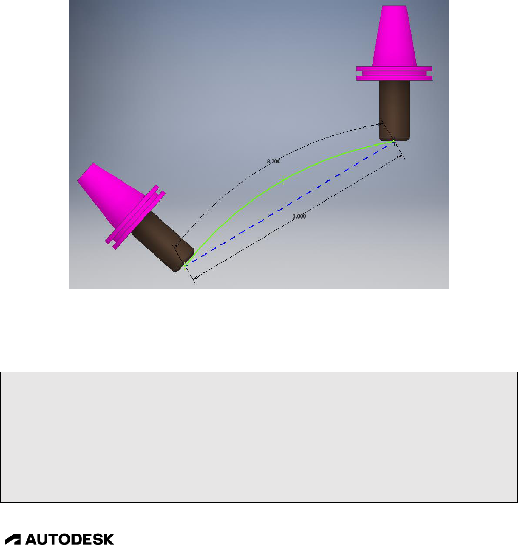
Multi-Axis Post Processors 8-232
CAM Post Processor Guide 2/2/24
probably supports direct Feed Per Minute (FPM) feedrates during multi-axis contouring moves and does
not require either Inverse Time or DPM feedrates.
Multi-axis feedrate calculations are handled by the post engine and and will work with all machine
configurations; table/table, head/head, and head/table. One capability of the multi-axis feedrate
calculation is that it considers the actual tool tip movement in reference to the rotary axes movement and
not just the straight-line movement along the programmed tool tip, creating more accurate multi-axis
feedrates. In the following picture the move along the arc caused by the movement of the rotary axis
(green arc) is used in the calculation instead of the straight-line move generated by HSM (blue line).
Actual Tool Path on Machine is Used in Feedrate Calculations
Multi-axis feedrate support is handled in the CAM Machine Definition or in the defineMachine function
for a hardcoded machine configuration.
// multi-axis feedrates
if (machineConfiguration.isMultiAxisConfiguration()) {
machineConfiguration.setMultiAxisFeedrate(
useTCP ? FEED_FPM : getProperty("useDPMFeeds") ? FEED_DPM : FEED_INVERSE_TIME,
9999.99, // maximum output value for inverse time feed rates
getProperty("useDPMFeeds") ? DPM_COMBINATION : INVERSE_MINUTES, //
INVERSE_MINUTES/INVERSE_SECONDS or DPM_COMBINATION/DPM_STANDARD
0.5, // tolerance to determine when the DPM feed has changed
1.0 // ratio of rotary accuracy to linear accuracy for DPM calculations
);

Multi-Axis Post Processors 8-233
CAM Post Processor Guide 2/2/24
}
Enabling Multi-Axis Feedrates
Variable
Description
feedMode
FEED_INIVERSE_TIME (inverse time), FEED_DPM (degrees per
minute), or FEED_FPM (programmed feedrate).
maximumFeedrate
Defines the maximum value that can be output for both inverse time and
degrees per minute feedrates.
feedType
Multi-axis feedrate options. For inverse time feedrates, the options are
INVERSE_MINUTES or INVERSE_SECONDS, defining the units of
time to use in inverse time feedrate calculations. For DPM feedrates, then
the options are DPM_STANDARD for straight degrees per minute
calculations or DPM_COMBINATION which uses a combination of
degrees per minute and linear feed per minute (this is the most typical for
machines that want a form of DPM feedrates).
outputTolerance
The tolerance for deciding whether to output a feedrate value or not. If
the feedrate value is within this tolerance of the previous feedrate value,
then it will be set to the previous value. This is used to minimize the
output of multi-axis feedrate numbers.
bpwRatio
Defines the pulse weight ratio for the rotary axes when DPM feedrates are
output as a combination of linear and rotary movements. The pulse
weight is a scale factor based on the rotary axes accuracy compared to the
linear axes accuracy. For example, it should be set to .1 when the linear
axes are output on .0001 increments and the rotary axes on .001
increments.
setMultiAxisFeedrate Parameters
If Inverse Time feedrates are supported you will need to create the inverseTimeOutput variable at the top
of the post processor code and if the accuracy of the Inverse Time feedrates is different than the standard
FPM feedrate you will also need to create a new format to associate with it. The gFeedModeModal
modal variable will also need to be defined for support of G93/G94 output if it does not already exist.
var gFeedModeModal = createModal({}, gFormat); // modal group 5 // G93-94
…
var inverseFormat = createFormat({decimals:4, forceDecimal:true});
…
var inverseTimeOutput = createVariable({prefix:"F", force:true}, feedFormat);
…
Create inverseTimeOutput Variable
Now there are other areas of the post processor that need to be changed to support these feedrate modes.
First, the onLinear5D function must have support added to receive and output the feedrate mode and to
output the feedrate value using the correct format.
function onLinear5D(_x, _y, _z, _a, _b, _c, feed, feedMode) {

Multi-Axis Post Processors 8-234
CAM Post Processor Guide 2/2/24
if (!currentSection.isOptimizedForMachine()) {
error(localize("This post configuration has not been customized for 5-axis simultaneous
toolpath."));
return;
}
// at least one axis is required
if (pendingRadiusCompensation >= 0) {
error(localize("Radius compensation cannot be activated/deactivated for 5-axis move."));
return;
}
var x = xOutput.format(_x);
var y = yOutput.format(_y);
var z = zOutput.format(_z);
var a = aOutput.format(_a);
var b = bOutput.format(_b);
var c = cOutput.format(_c);
// get feedrate number
var fMode = feedMode == FEED_INVERSE_TIME ? 93 : 94;
var f = feedMode == FEED_INVERSE_TIME ? inverseTimeOutput.format(feed) :
feedOutput.format(feed);
if (x || y || z || a || b || c) {
writeBlock(gFeedModeModal.format(fMode), gMotionModal.format(1), x, y, z, a, b, c, f);
} else if (f) {
if (getNextRecord().isMotion()) { // try not to output feed without motion
feedOutput.reset(); // force feed on next line
} else {
writeBlock(gFeedModeModal.format(fMode), gMotionModal.format(1), f);
}
}
}
onLinear5D Required Changes
You will need to reset the feedrate mode to FPM either at the end of the multi-axis operation or on a
standard 3-axis move. It is much easier to do this at the end of the section, otherwise you would have to
modify all instances that output feedrates, such as in onLinear, onCircular, onCycle, etc.
function onSectionEnd() {
…
if (currentSection.isMultiAxis()) {
writeBlock(gFeedModeModal.format(94)); // inverse time feed off
}
Reset FPM Mode in onSectionEnd

Multi-Axis Post Processors 8-235
CAM Post Processor Guide 2/2/24
writeBlock(gFeedModeModal.format(94), gMotionModal.format(1), gFormat.format(40), x, y, z,
f);
Optionally Reset FPM Mode in All Output Blocks with Feedrates
It is possible that your machine control does not support standard inverse time or DPM feedrates. If this
is the case you will need to write your own function to handle multi-axis feedrates. The
getMultiAxisMoveLength function will assist in the movement length calculations required for
calculating multi-axis feedrates. It takes the current position for the linear and rotary axes and will
calculate the tool tip, linear axes, and rotary axes lengths of the move from the previous location.
var length = machineConfiguration.getMultiAxisLength(x, y, z, a, b, c);
Calculate the Length of the Multi-Axis Move
getMultiAxisMoveLength will return MoveLength obect, which can then be accessed using the following
functions to obtain the different move lengths.
Function
Description
getRadialToolTipMoveLength
Calculated tool endpoint movement along the actual tool path.
getLinearMoveLength
Combined linear delta movement.
getRadialMoveLength
Combined rotary delta movement.
MoveLength Functions
var moveLength = getMultiAxisMoveLength(x, y, z, a, b, c);
var toolTipLength = moveLength.getRadialToolTipMoveLength();
var xyzLength = moveLength.getLinearMoveLength();
var abcLength = moveLength.getRadialMoveLength();
Retrieve the Calculated Move Lengths for the Tool Tip, Linear Axes, and Rotary Axes
8.8 Polar Interpolation
Polar interpolation replaces a linear axis in a 3-axis milling operation with a rotary axis. Polar
interpolation can be used to keep machining operations within the limits of the machine or simplify the
output of circular milling/drilling operations. It is sometimes referred to as XZC interpolation since it is
quite common to replace the Y-axis with the C-axis.
It can be supported in the control, for example using G12.1 on Fanuc style controls or handled within the
post processor. Machine control polar interpolation is typically supported on Mill/Turn machines.

Multi-Axis Post Processors 8-236
CAM Post Processor Guide 2/2/24
Sample Output Without and With Polar Interpolation
This section describes how to implement post processor generated polar interpolation support in your
post and how to activate it using a Manual NC command. The Haas Next Generation post processor has
polar interpolation implemented and can be used as a reference and to copy code from into your post.
8.8.1 Polar Interpolation Functions
The following functions are used with post generated polar interpolation. The setPolarMode and
setPolarFeedMode functions are defined in the post processor, all other functions are embedded in the
post processor kernel.
Without Polar Interpolation
With Polar Interpolation
Without Polar Interpolation
With Polar Interpolation

Multi-Axis Post Processors 8-237
CAM Post Processor Guide 2/2/24
Function
Description
activatePolarMode(toler, angle, axis)
Activates polar interpolation. tolerance specifies the
tolerance to use to keep the tool within the programmed
tool path. It is typically set to be tighter than the post
processor defined tolerance by a factor of 2 or 4
(tolerance / 2) to keep a smooth finish. angle defines the
current angle of the rotary axis used in polar
interpolation. axis defines the line that the tool can move
along during polar interpolation. A vector of (1, 0, 0)
keeps the tool along the X-axis.
deactivatePolarMode()
Disables polar interpolation.
getPolarPosition(x, y, z)
Returns the polar coordinates as a VectorPair for the
input x,y,z coordinates. The first vector is the XYZ
coordinates and the second vector is the ABC angles of
the polar position.
isPolarModeActive()
Returns true if polar mode is in effect.
setCurrentPositionAndDirection(position)
Sets the current XYZ and ABC position. position is a
VectorPair that contains the XYZ coordinates in the first
vector and the ABC angles in the second vector.
setPolarFeedMode(mode)
Defines the feedrate mode for polar interpolation. This
will usually be set to either Inverse Time or DPM
feedrates depending on capabilities of the control. This
multi-axis feedrate mode only needs to be changed for
polar interpolation if the machine supports TCP and
outputs FPM (programmed) feedrates with multi-axis
moves. Polar interpolation is not output using TCP, so
requires a different feedrate mode in this case. mode
determines if polar interpolation is being activated (true)
or deactivated (false). This function must be defined in
the post processor.
setPolarMode(section, mode)
Enables/disables polar interpolation mode for the
specified section. section should be set to currentSection.
mode can be set to true to enable polar interpolation or
false to disable it. This function must be defined in the
post processor.
Polar Interpolation Functions
The required polar interpolation variables and functions can be copied from the Haas Next Generation
post processor. These functions are bounded by the Start of polar interpolation and End of polar
interpolation comments.
// Start of polar interpolation
…
// End of polar interpolation
Copy the Required Polar Interpolation Code

Multi-Axis Post Processors 8-238
CAM Post Processor Guide 2/2/24
Most of this code will not require any modification. You may want to change the line/vector that polar
interpolation will move along during generation of the polar coordinates. This is defined by the
polarDirection variable at the top of the copied code. It is set to the X-axis (1, 0, 0) by default.
// Start of polar interpolation
var usePolarMode = false; // controlled by manual NC operation, enables polar interpolation for a single operation
var defaultPolarDirection = new Vector(1, 0, 0); // default direction for polar interpolation
var polarDirection = defaultPolarDirection; // vector to maintain tool at while in polar interpolation
Define the Axis Line for Polar Interpolation
You may have to modify the setPolarFeedMode to set the proper feedrate mode for polar interpolation.
If your machine does not support TCP, then this function can be blank and the same feedrate mode for
multi-axis and polar interpolation operations will be used.
function setPolarFeedMode(mode) {
if (machineConfiguration.isMultiAxisConfiguration()) {
machineConfiguration.setMultiAxisFeedrate(
!mode ? multiAxisFeedrate.mode : getProperty("useDPMFeeds") ? FEED_DPM :
FEED_INVERSE_TIME,
multiAxisFeedrate.maximum,
!mode ? multiAxisFeedrate.type : getProperty("useDPMFeeds") ? DPM_COMBINATION :
INVERSE_MINUTES,
multiAxisFeedrate.tolerance,
multiAxisFeedrate.bpwRatio
);
if (!receivedMachineConfiguration) {
setMachineConfiguration(machineConfiguration);
}
}
}
setPolarFeedMode to Use when TCP is Supported
function setPolarFeedMode(mode) {
}
setPolarFeedMode to Use when TCP is Not Supported
8.8.2 Manual NC Command to Enable Polar Interpolation
The Action Manual NC usePolarMode command is used to enable polar interpolation for a single
operation and must be placed prior to this operation. Polar interpolation will be automatically cancelled
after this operation, but since polar interpolation is handled in the post processor, you can make changes
to make the command modal.

Multi-Axis Post Processors 8-239
CAM Post Processor Guide 2/2/24
usePolarMode Manual NC Command
The usePolarMode Manual NC command is implemented in the onManualNC function.
function onManualNC(command, value) {
switch (command) {
case COMMAND_ACTION:
if (String(value).toUpperCase() == "USEPOLARMODE") {
usePolarMode = true;
}
break;
default:
expandManualNC(command, value);
}
}
Implementing the usePolarMode Manual NC Command
8.8.3 Calculating the Polar Interpolation Initial Angle
The initial XYZ position and ABC angles for polar interpolation is calculated in the defineWorkPlane
function.
function defineWorkPlane(_section, _setWorkPlane) {
var abc = new Vector(0, 0, 0);
if (machineConfiguration.isMultiAxisConfiguration()) { // use 5-axis indexing for multi-axis mode
if (isPolarModeActive()) { // calculate the initial ABC position for polar interpolation
abc = getCurrentDirection();
} else {
abc = _section.isMultiAxis() ? _section.getInitialToolAxisABC() :
getWorkPlaneMachineABC(_section.workPlane, _setWorkPlane);
}
// polar interpolation is treated as a multi-axis operation
if (_section.isMultiAxis() || isPolarModeActive()) {
cancelTransformation();
if (_setWorkPlane) {
if (activeG254) {
writeBlock(gFormat.format(255)); // cancel DWO

Multi-Axis Post Processors 8-240
CAM Post Processor Guide 2/2/24
activeG254 = false;
}
forceWorkPlane();
positionABC(abc, true);
}
} else {
Calculating the Initial ABC Position for Polar Interpolation in defineWorkPlane
Polar interpolation converts a 3-axis operation to a multi-axis operation, so it must be treated as such.
This means that the rotary axis must be unlocked prior to the initial positioning move, but not clamped
afterwards. This is handled in the setWorkPlane function.
if (!currentSection.isMultiAxis() && !isPolarModeActive()) {
onCommand(COMMAND_LOCK_MULTI_AXIS);
}
Don’t Lock the Rotary Axis During Polar Interpolation in setWorkPlane
There could be code in the onCommand function for unlocking the rotary axis that may need to be
changed also.
case COMMAND_UNLOCK_MULTI_AXIS:
var outputClampCodes = getProperty("useClampCodes") || currentSection.isMultiAxis()
|| isPolarModeActive();
if (outputClampCodes && machineConfiguration.isMultiAxisConfiguration() &&
(machineConfiguration.getNumberOfAxes() >= 4)) {
Unlocking the Rotary Axis During Polar Interpolation in onCommand
8.8.4 Initializing Polar Interpolation
The following modifications to onSection must be made to support polar interpolation. First, you need to
enable polar interpolation. This code is usually placed prior to the defineWorkPlane call.
// Use new operation property for polar milling
if (currentSection.machiningType &&
(currentSection.machiningType == MACHINING_TYPE_POLAR)) {
usePolarMode = true;
// Update polar coordinates direction according to operation property
polarDirection = currentSection.polarDirection;
}
// enable polar interpolation
if (usePolarMode && (tool.type != TOOL_PROBE)) {
if (polarDirection == undefined) {
error(localize("Polar direction property must be a vector - x,y,z."));
return;

Multi-Axis Post Processors 8-241
CAM Post Processor Guide 2/2/24
}
setPolarMode(currentSection, true);
}
defineWorkPlane(currentSection, false);
var initialPosition = isPolarModeActive() ? getCurrentPosition() :
getFramePosition(currentSection.getInitialPosition());
forceAny();
Enabling Polar Interpolation in onSection
8.8.5 Disabling Polar Interpolation
Polar interpolation is disabled after each operation in the onSectionEnd function when it is only active
for a single operation.
function onSectionEnd() {
…
setPolarMode(currentSection, false);
}
Disabling Polar Interpolation in onSectionEnd
8.8.6 Enabling Polar Interpolation in Drilling Cycles
Polar interpolation is supported for both 3-axis milling operations and in drilling cycles. The milling
operations will be converted to multi-axis operations once polar interpolation is activated, calling
onRapid5D and onLinear5D linear motion. No modifications to these functions need to be made to
support polar interpolation.
Drilling cycle locations will still call onCyclePoint during polar interpolation, so modifications must be
made to output the rotary axis with the cycle positions. This is done by making the following
modification to the getCommonCycle function for the first point of a cycle operation.
function getCommonCycle(x, y, z, r, c) {
forceXYZ();
if (isPolarModeActive()) { // format polar interpolation position
var polarPosition = getPolarPosition(x, y, z);
return [xOutput.format(polarPosition.first.x), yOutput.format(polarPosition.first.y),
zOutput.format(polarPosition.first.z),
aOutput.format(polarPosition.second.x),
bOutput.format(polarPosition.second.y),
cOutput.format(polarPosition.second.z),
“R” + xyzFormat.format®];

Support for Machine Simulation 9-242
CAM Post Processor Guide 2/2/24
} else { // format linear interpolation position
if (incrementalMode) {
zOutput.format(c);
return [xOutput.format(x), yOutput.format(y),
"Z" + xyzFormat.format(z - r),
"R" + xyzFormat.format(r - c)];
} else {
return [xOutput.format(x), yOutput.format(y),
zOutput.format(z),
"R" + xyzFormat.format(r)];
}
}
}
Formatting the Polar Interpolation Cycle Position in getCommonCycle
In the onCyclePoint function you need to format the cycle location for polar interpolation for the 2
nd
through final cycle point.
// 2nd through nth cycle point
} else {
if (cycleExpanded) {
expandCyclePoint(x, y, z);
} else {
if (isPolarModeActive()) { // format polar interpolation position
var polarPosition = getPolarPosition(x, y, z);
writeBlock(xOutput.format(polarPosition.first.x), yOutput.format(polarPosition.first.y),
zOutput.format(polarPosition.first.z),
aOutput.format(polarPosition.second.x), bOutput.format(polarPosition.second.y),
cOutput.format(polarPosition.second.z));
return;
}
Formatting the Polar Interpolation Cycle Position in onCyclePoint
9 Support for Machine Simulation
Fusion can simulate the movements of a machine when replaying an operation using the Simulate with
Machine process when a Machine Definition is attached to the CAM Setup and it contains a model of
the machine.

Support for Machine Simulation 9-243
CAM Post Processor Guide 2/2/24
Simulating Machine Movements During Playback
Most Machine Definitions available in the Machine Library have associated CAD models of the
machine that can be used for machine simulation. Checking the Simulation ready box in the Filters tab
will display all machines that have a machine model and can be used for simulation. These will be
shown in the Machine Definition list with a 3D cube next to their name.
Machine Definition with a Machine Model Suitable for Simulation
9.1 Post Processor Support for Machine Simulation
Post processors that support machine simulation will have CAPABILITY_MACHINE_SIMULATION
defined as one of their capabilities.
capabilities = CAPABILITY_MILLING | CAPABILITY_MACHINE_SIMULATION;
Specifying Machine Simulation Capabilities in the Post

Support for Machine Simulation 9-244
CAM Post Processor Guide 2/2/24
The post will also have the activateMachine function present. One thing to note is that the post
processor cannot make changes to the machine configuration when machine simulation is supported.
This means that no calls to the machineConfiguration.set--- functions can be made nor can
setMachineConfiguration be called.
There are some posts that can enable rotary axes using a post property. You cannot use this property to
define the rotary axes if you wish to use machine simulation, the rotary axes must be defined in the
external Machine Definition.
Using a Property to Define the Rotary Axis is not Allowed for Machine Simulation
9.2 Placing the Part onto the Machine
Once you have a Machine Definition with a machine model assigned to the Setup you will need to place
the part on the machine. This is handled in the tab of the Setup dialog box. You will need to select
the Part Attach Point and the Table Attach Point. Optionally, you can shift the part by distances in the
X, Y, and Z directions.
Placing the Part onto the Machine
9.3 Obtaining the Part/Machine Attach Points
var partAttachPoint = section.getPartAttachPoint();
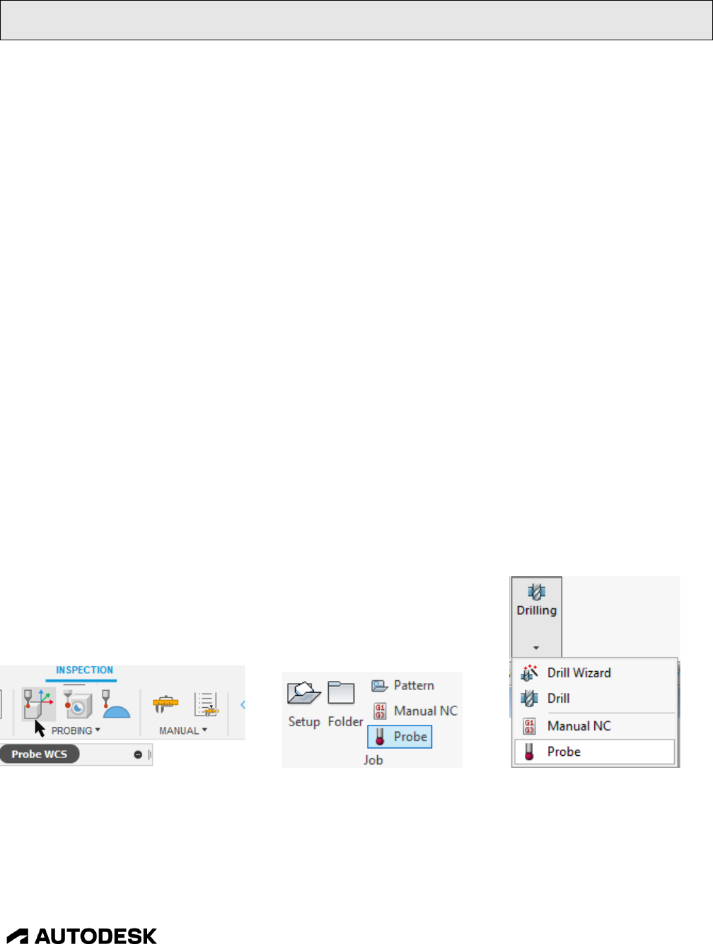
Adding Support for Probing 10-245
CAM Post Processor Guide 2/2/24
var tableAttachPoint = machineConfiguration.getTableAttachPoint();
var headAttachPoint = machineConfiguration.getHeadAttachPoint();
Obtaining the Part/Machine Attach Points
The getPartAttachPoint function returns the location on the part where it is attached to the machine
model. This location will be in reference to the Work Coordinate System (WCS) Origin as defined in
the CAM Setup.
The getTableAttachPoint() function returns the location on the machine where the part is attached. This
is the same location as the part attach point except that it is in the Machine Coordinate System (MCS) in
relation to where the machine origin is defined in the machine model.
The getHeadAttachPoint() function returns the location on the machine where the tool is attached to the
spindle in the Machine Coordinate System (MCS).
10 Adding Support for Probing
Fusion, Inventor CAM, and HSM have support for multiple styles of probing operations, including WCS
Probing, Geometry Probing, and Surface Inspection. While the probing capabilities are supported by
many of the library post processors, they are not supported by all of them and custom post processors
may not have these capabilities. This chapter discusses the required changes to a post processor to
support the probing operations.
10.1 WCS Probing
WCS Probing is defined as probing operations that are used to probe the part for the purpose of defining
a Work Coordinate System. While all Autodesk CAM products support WCS Probing, you will find
these operations in a different area of the interface for each of the products.
Fusion Inventor CAM HSMWorks
You can check the post processor you are working with to see if it supports WCS Probing. The easiest
method is to try to run a probing operation against the post, the post will fail if probing is not supported.
You may see an error message complaining about the spindle speed being out of range (probe operations
do not turn on the spindle) or a message that states that the probing cycle must be handled in the post
processor.

Adding Support for Probing 10-246
CAM Post Processor Guide 2/2/24
###############################################################################
Error: Spindle speed out of range.
Error at line: 735
Error in operation: 'WCS Probe1'
Failed while processing onSection() for record 261.
###############################################################################
Spindle Speed Error Message
###############################################################################
Error: The probe cycle 'probing-xy-outer-corner' is machine specific and must always be handled in
the post configuration.
Error in operation: 'WCS Probe1'
Failed while processing onCycle() for record 280.
###############################################################################
Machine Specific Error Message
If you receive either of these messages, then probing is not supported in your post processor and you
will need to add it.
10.1.1 Probing Operations
There is a sample model available for testing the probing logic in a post processor. In Fusion it is
contained int the CAM Samples/Post Processor folder. This model contains a part designed for testing
probing cycles using the available WCS Probing operations.
Sample Probing Part
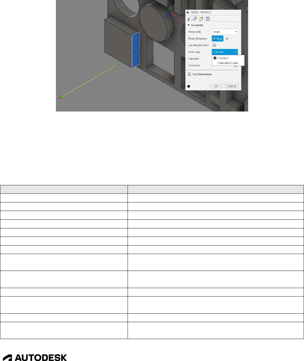
Adding Support for Probing 10-247
CAM Post Processor Guide 2/2/24
One thing you will notice when creating a probing operation is that interface is intelligent enough to
only give you the probing operation types that apply to the type of geometry selected. For example, if
you select a planar face perpendicular to the X-axis, then the only operations available to you are the X
surface and Angle along X-axis operations.
Intelligent Probe Selection
The WCS Probing operations are considered a canned cycle in the post processor and therefore are
output in the onCyclePoint function, with the probe type being stored in the cycleType variable. The
following table lists the available probing operations. You should note that probing cycles cannot be
expanded and must be handled in the post processor, either by performing the cycle, by giving an error,
or by expanding the cycle in the post processor.
cycleType
Description
probing-x
Probes a wall perpendicular to the X-axis.
probing-y
Probes a wall perpendicular to the Y-axis.
probing-z
Probes a wall perpendicular to the Z-axis.
probing-x-wall
Probes a wall thickness in the X-axis
probing-y-wall
Probes a wall thickness in the Y-axis
probing-x-channel
Probes the open distance between two walls in the X-axis
probing-y-channel
Probes the open distance between two walls in the Y-axis
probing-x-channel-with-island
Probes the open distance between two walls with an
island between the walls in the X-axis
probing-y-channel-with-island
Probes the open distance between two walls with an
island between the walls in the Y-axis
probing-xy-circular-boss
Probes the outer wall of a circular boss
probing-xy-circular-partial-boss
Probes the outer wall of a circular boss that is not a
complete 360 degrees
probing-xy-circular-hole
Probes the inner wall of a circular hole
probing-xy-circular-partial hole
Probes the inner wall of a circular hole that is not a
complete 360 degrees

Adding Support for Probing 10-248
CAM Post Processor Guide 2/2/24
cycleType
Description
probing-xy-circular-hole-with-island
Probes the inner wall of a circular hole with an island in
the hole
probing-xy-rectangular-boss
Probes the outer walls of a rectangular protrusion
probing-xy-rectangular-hole
Probes the inner walls of a rectangular hole
probing-xy-rectangular-hole-with-island
Probes the inner walls of a rectangular hole with an island
in the hole
probing-xy-inner-corner
Probes an inner corner. Modifies the origin and rotation
of the part.
probing-xy-outer-corner
Probes an outer corner. Modifies the origin and rotation
of the part.
probing-x-plane-angle
Probes a wall at an angle to the X-axis. Modifies the
rotation of the part.
probing-y-plane-angle
Probes a wall at an angle to the Y-axis. Modifies the
rotation of the part.
Probing Cycles
The parameters defined in the WCS Probing operation are passed to the cycle functions using the cycle
object. The following variables are available and are referenced as ‘cycle.parameter’.
Parameter
Description
angleAskewAction
This parameter will only be defined with an angular probing cycle
when the Askew box is checked. The only valid setting when it is
defined is the string stop-message.
approach1
The direction the probe moves at it approaches the part. It is a string
variable and can be either positive or negative.
approach2
The direction the probe moves as it approaches the part for the second
face of a multi-face operation. It is a string variable and can be either
positive or negative.
bottom
The final depth position along the probe axis to touch the part.
clearance
The height the probe rapids to on its way to the start of the probing
operation and the position it returns to after the probing operation is
finished.
depth
The unsigned incremental distance from the top of the part along the
probe axis where the probe will touch the part.
feedrate
The feedrate the probe will approach the part at.
hasAngleTolerance
Set to 1 if an angular tolerance is specified. The angular tolerance is
stored in the toleranceAngle parameter.
hasPositionalTolerance
Set to 1 if a positional tolerance is specified. The positional tolerance
is stored in the tolerancePosition parameter.
hasSizeTolerance
Set to 1 if a size tolerance is specified. The size tolerance is stored in
the toleranceSize parameter.
incrementComponent
Set to 1 if the Increment Component box is checked under Print
Results.

Adding Support for Probing 10-249
CAM Post Processor Guide 2/2/24
Parameter
Description
outOfPositionAction
This parameter will only be defined when the Out of Position box is
checked. The only valid setting when it is defined is the string stop-
message.
printResults
Set to 1 when the Print Results box is checked in the probing
operation.
probeClearance
The approach distance in the direction of the probing operation. The
probe will be positioned at this clearance distance prior to
approaching the part.
probeOvertravel
The maximum distance the probe can move beyond the expected
contact point and still record a measurement.
probeSpacing
The probe spacing between points on the selected face for Angle style
probing.
retract
The height to feed from to the probing level and to retract the probe to
after probing is finished.
stock
The top of the part.
toleranceAngle
The acceptable angular deviation of the geometric feature.
tolerancePosition
The acceptable positional deviation of the geometric feature.
toleranceSize
The acceptable size deviation of the geometric feature.
width1
The width of the boss or hole being probed.
width2
The width of the secondary walls (Y-axis) of a rectangular boss or
hole being probed.
wrongSizeAction
This parameter will only be defined when probing a feature that
defines a fixed size and the Wrong Size box is checked. The only
valid setting when it is defined is the string stop-message.
Probing Parameters
10.1.2 Adding the Core Probing Logic
Adding WCS Probing support requires the main logic to output the probing cycle, supporting functions,
and some logic added to the main sections of the post processor. You should first open a post processor
that contains support for probing before starting to add probing to your post processor, since the logic
and most of the code will remain the same. Most of the generic post processors use Renishaw style
probing Macros (Fanuc, Haas, etc.), but there are also controls that support probing without the use of
these Macros, such as the Datron, Heidenhain, and Siemens controls. Be sure to start with closest match
to the machine you are creating a post processor for. The examples used in this chapter use the code for
the Renishaw style probing Macros.
The following functions support angular probing and safe probe positioning. They may have to be
modified to match the requirements of your control. The code shown is for a Fanuc style control. They
should be added prior to the onCyclePoint function.
Function
Description
approach
Converts the cycle approach string to a number (-1/1).

Adding Support for Probing 10-250
CAM Post Processor Guide 2/2/24
Function
Description
setProbeAngleMethod
Determines the output method (G68, G54.4, rotational)
for angular probing cycles.
setProbeAngle
Outputs the rotational blocks for angular probing cycles.
This output may have to be modified to match your
control.
protecedProbeMove
Positions the probe in a protected mode (P9810).
getProbingArguments
Formats the standard codes for all probing cycles based
on the probing cycle parameters. This function is usually
located after the onCyclePoint function and may have to
be modified to match your control.
Required Probe Functions
/** Convert approach to sign. */
function approach(value) {
…
}
function setProbeAngleMethod() {
…
}
/** Output rotation offset based on angular probing cycle. */
function setProbeAngle() {
…
}
function protectedProbeMove(_cycle, x, y, z) {
…
}
function getProbingArguments(cycle, updateWCS) {
…
}
Required Angular and Safe Positioning Probe Functions
The core logic for probing is in the onCyclePoint function. The first part of the code to copy into your
post is at the top of the onCyclePoint function.
if (isProbeOperation()) {
if (!useMultiAxisFeatures && !isSameDirection(currentSection.workPlane.forward, new Vector(0,
0, 1))) {
if (!allowIndexingWCSProbing && currentSection.strategy == "probe") {
error(localize("Updating WCS / work offset using probing is only supported by the CNC in the
WCS frame."));

Adding Support for Probing 10-251
CAM Post Processor Guide 2/2/24
return;
}
}
if (printProbeResults()) {
writeProbingToolpathInformation(z - cycle.depth + tool.diameter / 2);
inspectionWriteCADTransform();
inspectionWriteWorkplaneTransform();
if (typeof inspectionWriteVariables == "function") {
inspectionVariables.pointNumber += 1;
}
}
protectedProbeMove(cycle, x, y, z);
}
Required Probing Code at Top of onCyclePoint
All probing operations are considered a separate operation and are not modal. The following code in the
onCyclePoint function should directly follow the required probing code you just added and needs to be
modified as shown in the highlighted code to support probing.
if (isFirstCyclePoint() || isProbeOperation()) {
if (!isProbeOperation()) {
// return to initial Z which is clearance plane and set absolute mode
repositionToCycleClearance(cycle, x, y, z);
}
Required Modifications for Probing Support
The code that outputs the probing calls is usually located after the drilling cycle logic in the main switch
block. Copy all code that contains the case statements for probing operations.
switch (cycleType) {
case “drilling”:
…
case “probing-x”: // copy from this line to before the “default” case
…
default:
Calling the Probe Macro
Add the following code to the onCycleEnd function to end the probing operation.
function onCycleEnd() {
if (isProbeOperation()) {
zOutput.reset();
gMotionModal.reset();

Adding Support for Probing 10-252
CAM Post Processor Guide 2/2/24
writeBlock(gFormat.format(65), "P" + 9810, zOutput.format(cycle.retract)); // protected
retract move
} else {
…
}
10.1.3 Adding the Supporting Probing Logic
There are various locations that contain support logic for probing operations in the post processor.
Some of this code may already be in your post processor. The format used for the Probe WCS code
needs to be added at the top of the post where other formats are defined, if it is not already present in the
post processor.
var probeWCSFormat = createFormat({decimals:0, forceDecimal:true});
Required for Formatting the Probe WCS Code
The gRotationModal modal is used to manage the output of the rotation codes (G68, G68.2, etc.). It is
possible that this variable is already defined in the post processor, but may have to be updated to support
probing. It should be defined as shown.
var gRotationModal = createModal({
onchange: function () {
if (probeVariables.probeAngleMethod == "G68") {
probeVariables.outputRotationCodes = true;
}
}
}, gFormat); // modal group 16 // G68-G69
Defining the gRotationModal Modal
The following variables are used to control the output of probing features probing output and should be
defined in the fixed settings section at the top of the post processor.
var allowIndexingWCSProbing = false; // specifies probe WCS with tool orientation is supported
var probeVariables = {
outputRotationCodes: false, // defines if it is required to output rotation codes
probeAngleMethod : "OFF", // OFF, AXIS_ROT, G68, G54.4
compensationXY : undefined
};
Add to Fixed Settings Section
Variable
Description
allowIndexingWCSProbing
Some controls do not allow for WCS probing operations when the tool
orientation is at an angle the XY-plane, i.e. the rotary tables are not at 0
degrees. If this is the case for your machine, then disable this variable
by defining it to be false. If WCS probing is allowed when the rotary
axes are not at 0 degrees, then set this variable to true.

Adding Support for Probing 10-253
CAM Post Processor Guide 2/2/24
outputRotationCodes
Controls the output of the angular probing codes. This variable is
controlled by the post processor and should be set to false.
probeAngleMethod
Defines the angular probing method to use. This method is usually
defined by the post processor in the setProbingAngleMethod function
and can be controlled by a post processor property. It should be set to
OFF. Other valid values are AXIS_ROT (used when a C-axis rotary
table is defined), G68 (the standard rotation method), or G54.4 (based
on the post processor property useG54x4).
compensationXY
Controls the output of the XY compensation variables in angular
probing. This variable is controlled by the post processor and should be
set to undefined.
Probing Settings
Add the following variables to the collected state section at the top of the post processor.
var g68RotationMode = 0;
var angularProbingMode;
Add to Collected State Section
The following function and variable definition should be added prior to the onParameter function. The
onParameter function should also have the shown conditional added if it is not there.
function printProbeResults() {
return currentSection.getParameter("printResults", 0) == 1;
}
var probeOutputWorkOffset = 1;
function onParameter(name, value) {
if (name == "probe-output-work-offset") {
probeOutputWorkOffset = (value > 0) ? value : 1;
}
Add Prior to and to onParameter Function
The following code needs to be added to the onSection function.
if (tool.type != TOOL_PROBE) {
var outputSpindleSpeed = insertToolCall || forceSpindleSpeed || isFirstSection() ||
rpmFormat.areDifferent(spindleSpeed, sOutput.getCurrent()) ||
(tool.clockwise != getPreviousSection().getTool().clockwise);
…
}
Don’t Output Spindle Speed with a Probe Tool
setProbeAngle(); // output probe angle rotations if required

Adding Support for Probing 10-254
CAM Post Processor Guide 2/2/24
// set coolant after we have positioned at Z
setCoolant(tool.coolant);
Set Rotation Based on Angular Probing Results
if (isProbeOperation()) {
validate(probeVariables.probeAngleMethod != "G68", "You cannot probe while G68
Rotation is in effect.");
validate(probeVariables.probeAngleMethod != "G54.4", "You cannot probe while workpiece
setting error compensation G54.4 is enabled.");
writeBlock(gFormat.format(65), "P" + 9832); // spin the probe on
inspectionCreateResultsFileHeader();
} else {
// surface Inspection
if (isInspectionOperation() && (typeof inspectionProcessSectionStart == "function")) {
inspectionProcessSectionStart();
}
}
// define subprogram
subprogramDefine(initialPosition, abc, retracted, zIsOutput);
retracted = false;
}
Add at the end of the onSection Function
Coolant should be disabled during probing operations, so make sure that the following conditional is in
the getCoolantCodes function.
function getCoolantCodes(coolant) {
var multipleCoolantBlocks = new Array(); // create a formatted array to be passed into the outputted
line
if (!coolants) {
error(localize("Coolants have not been defined."));
}
if (isProbeOperation()) { // avoid coolant output for probing
coolant = COOLANT_OFF;
}
Disable Coolant for Probing Operations
The probe should be turned off and angular probing codes output in the onSectionEnd function.
function onSectionEnd() {
…
if (isProbeOperation()) {
writeBlock(gFormat.format(65), "P" + 9833); // spin the probe off
if (probeVariables.probeAngleMethod != "G68") {

Adding Support for Probing 10-255
CAM Post Processor Guide 2/2/24
setProbeAngle(); // output probe angle rotations if required
}
}
}
10.1.4 Adding Support for Printing Probe Results
A property can be added for controlling whether the probing results are output to a single file or in
separate files for each probe/inspection operation.
singleResultsFile: {
title : "Create single results file",
description: "Set to false if you want to store the measurement results for each probe / inspection
toolpath in a separate file",
group : 0,
type : "boolean",
value : true,
scope : "post"
}
Add a Property to Control the Output of the Probe Results into a Single or Multiple Files
The following functions should be included if your control supports the printing of probing results. The
modifications that you already made to support probing will handle the calls to these functions to output
the probing results. These functions are defined consecutively and are usually located after the
writeRetract function.
var isDPRNTopen = false;
function inspectionCreateResultsFileHeader() {
…
}
function getPointNumber() {
…
}
function inspectionWriteCADTransform() {
…
}
function inspectionWriteWorkplaneTransform() {
…
}
function writeProbingToolpathInformation(cycleDepth) {

Adding Support for Probing 10-256
CAM Post Processor Guide 2/2/24
…
}
Include the Probing Results Functions
In the onClose function you will need to close the probe results file.
if (isDPRNTopen) {
writeln("DPRNT[END]");
writeBlock("PCLOS");
isDPRNTopen = false;
if (typeof inspectionProcessSectionEnd == "function") {
inspectionProcessSectionEnd();
}
}
Closing the Probing Results File
10.2 Geometry Probing
Geometry Probing behaves similarly to WCS Probing. It is used to measure geometric features on the
part during machining. The measured geometric features are checked against specified tolerances for
size and position. Based on the result, you can update the tool wear, or instruct the machine to stop
machining if the feature is out of tolerance. Geometry Probing is initiated using the Probe Geometry
operation listed in the PROBING menu.
Geometry Probing Operation
The Pitch Circle Diameter (PCD) probing cycles are an addition to Geometry Probing that do not exist
in WCS Probing. Like all other probing cycles, the PCD cycle types are stored in the cycleType
variable.
cycleType
Description
probing-xy-pcd-hole
Probes holes around a PCD.
probing-xy-pcd-boss
Probes bosses around a PCD.
Pitch Circle Diameter (PCD) Probing Cycles
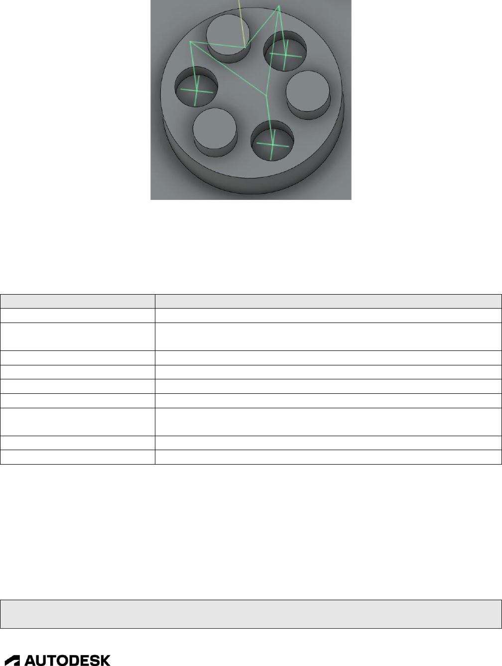
Adding Support for Probing 10-257
CAM Post Processor Guide 2/2/24
PCD Probing Geometry
Like in WCS Probing, the parameters defined in the Geometry Probing operation are passed to the cycle
functions using the cycle object. These are in addition to the parameters defined for WCS Probing,
which are also available in Geometry Probing. The following variables are available and are referenced
as ‘cycle.parameter’.
Parameter
Description
numberOfSubfeatures
Number of geometric entities in a PCD probing operation.
pcdStartingAngle
The starting angle of the first geometric entity to be probed in a PCD
probing operation.
toolDiameterOffset
Defines the tool diameter offset register used to machine the feature.
toolLengthOffset
Defines the tool length offset register used to machine the feature.
toolWearErrorCorrection
The percentage of the deviation to update the tool wear by.
toolWearUpdateThreshold
The minimum deviation that will trigger a tool wear update.
updateToolWear
Enabled when tool wear compensation should be activated on the
controller.
widthFeature
The diameter of the geometric feature for a PCD probing operation.
widthPCD
The pitch circle diameter (PCD) of the geometric features.
Geometry Probing Parameters
To add Geometry Probing to your post you will first need to implement WCS Probing. After this there
are only minor changes required to support Geometry Probing.
The probeMultipleFeatures variable instructs the post engine that multiple geometric entities can be
probed in a single operation. The probing logic in all posts now support this feature, so it should be set
to true. It should be defined with the other post engine variables (allowedCircularPlanes, highFeedrate,
etc.).
highFeedrate = (unit == IN) ? 500 : 5000;
probeMultipleFeatures = true;

Adding Support for Probing 10-258
CAM Post Processor Guide 2/2/24
Enable the Probing of Multiple Geometric Entities
If the control supports PCD probing cycles be sure to include cases for these cycles in onCyclePoint,
where the other probing cycle code is located.
case "probing-xy-pcd-hole":
protectedProbeMove(cycle, x, y, z);
writeBlock(
gFormat.format(65), "P" + 9819,
"A" + xyzFormat.format(cycle.pcdStartingAngle),
"B" + xyzFormat.format(cycle.numberOfSubfeatures),
"C" + xyzFormat.format(cycle.widthPCD),
"D" + xyzFormat.format(cycle.widthFeature),
"K" + xyzFormat.format(z - cycle.depth),
"Q" + xyzFormat.format(cycle.probeOvertravel),
getProbingArguments(cycle, false)
);
if (cycle.updateToolWear) {
error(localize("Action -Update Tool Wear- is not supported with this cycle."));
return;
}
break;
case "probing-xy-pcd-boss":
protectedProbeMove(cycle, x, y, z);
writeBlock(
gFormat.format(65), "P" + 9819,
"A" + xyzFormat.format(cycle.pcdStartingAngle),
"B" + xyzFormat.format(cycle.numberOfSubfeatures),
"C" + xyzFormat.format(cycle.widthPCD),
"D" + xyzFormat.format(cycle.widthFeature),
"Z" + xyzFormat.format(z - cycle.depth),
"Q" + xyzFormat.format(cycle.probeOvertravel),
"R" + xyzFormat.format(cycle.probeClearance),
getProbingArguments(cycle, false)
);
if (cycle.updateToolWear) {
error(localize("Action -Update Tool Wear- is not supported with this cycle."));
return;
}
break;
PCD Probing Support in onCyclePoint
10.3 Inspect Surface
The Inspect Surface operation creates a probing strategy that specifies contact points across the surfaces
of the model to be measured by a probe while the part is still on the machine tool. The results can then

Adding Support for Probing 10-259
CAM Post Processor Guide 2/2/24
be imported and compared against the model to identify if the manufactured part is in or out of
tolerance.
Inspection streamlines the manufacturing process by letting you identify problem areas and decide on
any rework needed early in the process. It also helps to reduce the need to move parts between the
machine tool and a measuring device.
Surface Inspection is initiated using the Inspect Surface operation listed in the INSPECTION/PROBING
menu.
Inspect Surface Operation
If you wish to use the Inspect Surface operations, you will need a post processor that will allow you to
output and run these inspection paths on your machine. You can either use one of the generic Inspection
post processors available on the Post Library for Autodesk Fusion, or modify your current milling post
which is already set up for your machine to add in the inspection functionality. You will need to add
support for probing to your post processor before adding the inspection capabilities.
The Inspection post processors will have the inspection or inspect surface suffix appended to the name
of the post processor. These are the only post processors that support Inspect Surface operations. You
will need to use one of these generic posts as a source for adding the inspection code to your post
processor.
10.3.1 Inspect Surface Operations
Inspect Surface operations differ from the other probing operations, in that you will select points on the
face of the part to inspect instead of individual features of the part.

Adding Support for Probing 10-260
CAM Post Processor Guide 2/2/24
Surface Inspect Interface
The Surface Inspect operations are considered a cycle in the post processor and therefore call the
onCyclePoint function, though they are expanded in the inspectionCycleInspect function. The standard
cycleType variable to define the cycle type is not set for Surface Inspect operations, but rather the
isInspectionOperation function is used to determine if it is a Surface Inspection cycle. This is further
explained in the Adding the Supporting Surface Inspect Logic section. Unlike other cycles that pass a
single point to the onCyclePoint function, the Surface Inspect cycle will contain the following 3 points
per cycle location, with each location generating a separate and subsequent call to onCyclePoint.
Location
How to determine
Description
First
isFirstCyclePoint()
Safe move to approach inspection location
Second
(default)
Inspection move
Third
isLastCyclePoint()
Retract move
Three Points per Inspection Location
10.3.2 Inspection Parameters
The parameters defined in the Inspect Surface operation are passed to the inspection functions using
either the cycle object or through section parameters (getParameter). These parameters are handled in
the core Surface Inspect functions that are copied from an existing inspection post processor. Standard
probing parameters can be referenced in the inspection functions.
The following variables are referenced as ‘cycle.parameter’.
Cycle Parameter
Description
linkFeed
The feedrate used to position between inspection locations.
measureFeed
The feedrate used to approach the part.
nominalI
The I-component of the vector normal to the surface inspection point.

Adding Support for Probing 10-261
CAM Post Processor Guide 2/2/24
Cycle Parameter
Description
nominalJ
The J-component of the vector normal to the surface inspection point.
nominalK
The K-component of the vector normal to the surface inspection point.
nominalX
The X-axis position of the inspection point.
nominalY
The Y-axis position of the inspection point.
nominalZ
The Z-axis position of the inspection point.
outOfPositionAction
This parameter will only be defined when the Out of Position box is
checked. The only valid setting when it is defined is the string stop-
message.
pointID
The numeric ID of the inspection point.
safeFeed
The feedrate at which to approach the part.
Inspection cycle Parameters
The following parameters are inspection specific and are prefixed with the operation: string. They are
referenced using the getParameter("operation:parameter ") function.
Parameter
Description
inspectUpperTolerance
The lower limit distance at which an inspected point is considered
within tolerance of the model.
inspectSurfaceOffset
The positive or negative distance from the model from where
inspection points are measured.
inspectUpperTolerance
The upper limit distance at which an inspected point is considered
within tolerance of the model.
Inspection Parameters
10.3.3 Adding the Core Inspect Surface Logic
Adding Surface Inspect support requires the main logic to be copied directly from a post processor that
already supports inspection, and logic added to the main sections of the post processor. You should first
open a post processor that contains support for inspection before starting to add Inspect Surface support
to your post processor, since the logic and most of the code will remain the same. As of this writing, the
following post processors have support for inspection, notice that all of them are named with the inspect
surface or inspection suffix.
Post Library Name
Filename
DATRON next Inspect Surface
datron next inspect surface.cps
Fanuc Inspection
fanuc inspection.cps
HAAS (pre-NGC) Inspect Surface
haas inspect surface.cps
HAAS – Next Generation Control Inspect Surface
haas next generation inspect surface.cps
Heidenhain Inspection
heidenhain inspection.cps
Hurco Inspect Surface
hurco inspect surface.cps
Results file generator for probing and inspect surface
result generator inspect surface.cps
Siemens SINUMERIK 840D Inspection
siemens 840D inspection.cps
Post Processors that Support Surface Inspect Operations

Adding Support for Probing 10-262
CAM Post Processor Guide 2/2/24
You can also search the online Post Library for Autodesk Fusion to see if any other post processors have
been added with inspection capabilities.
Search for Posts that Support Surface Inspect Operations
The main code for Inspect Surface logic is located at the end of the post processor. You will need to
copy from the definition of capabilities located after the onClose or onTerminate function to the end of
the file and add this code to the end of your post processor.
capabilities = |= CAPABILITY_INSPECTION;
description = "HAAS - Next Generation Control Inspect Surface";
longDescription = "Generic post for the HAAS Next Generation control with inspect surface
capabilities.";
Copy From this Code to the End of the File for Core Surface Inspect Logic
10.3.4 Adding the Supporting Inspect Surface Logic
There are a number of locations that contain support logic for Inspect Surface operations in the post
processor. You can refer to any of the generic post processors that support Inspect Surface operations
for an example on where this code is implemented.
Add the following code at the end of the onOpen function.
// Probing Surface Inspection
if (typeof inspectionWriteVariables == "function") {
inspectionWriteVariables();
}
Add to the End of the onOpen Function

Additive Capabilities and Post Processors 11-263
CAM Post Processor Guide 2/2/24
For multi-axis machines it is important that an actual machine configuration is defined and is not reliant
on 3+2 plane codes and/or IJK output. Please refer to the Multi-Axis Post Processors section for a
description on implementing multi-axis support to your post processor.
At the end of the onSection function, but before any subprograms are defined, add the following code.
if (isInspectionOperation(currentSection) && (typeof inspectionProcessSectionStart == "function"))
{
inspectionProcessSectionStart();
}
Initialize the Surface Inspect Operation
At the top of the onCyclePoint function add in the following code.
if (isInspectionOperation(currentSection) && (typeof inspectionCycleInspect == "function")) {
inspectionCycleInspect(cycle, x, y, z);
return;
}
Call the Controlling Surface Inspect Function
At the start of the onSectionEnd function add the following code. The writeBlock statement in this
example will differ between the machine post processors.
if (isInspectionOperation() && !isLastSection()) {
// the following logic will differ depending on the post processor
writeBlock(gFormat.format(103), "P0", formatComment("LOOKAHEAD ON"));
}
Finalize the Surface Inspect Operation
At the end of the onClose function, but before any subprogram statements, add the following code after
the results file is closed.
if (typeof inspectionProgramEnd == "function") {
inspectionProgramEnd();
}
Finalize the Surface Inspect Program
11 Additive Capabilities and Post Processors
So far in this guide we’ve discussed post processors as they pertain to subtractive machining, but Fusion
also supports Additive FFF (fused filament fabrication) printers. This chapter discusses the basics of
selecting a machine capable of additive manufacturing, generating an additive tool path, creating output,
and the details of an additive post processor.
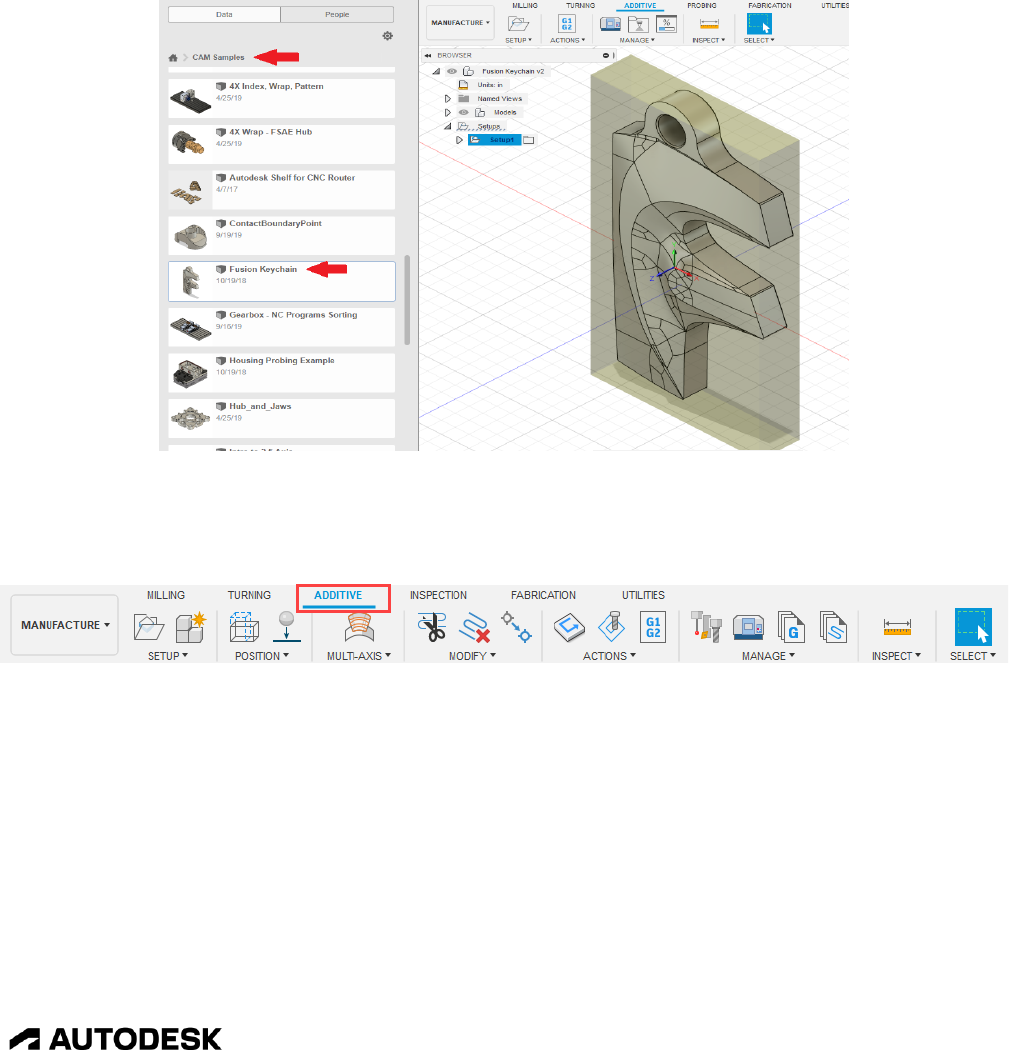
Additive Capabilities and Post Processors 11-264
CAM Post Processor Guide 2/2/24
11.1 Getting Started
This section will give an overview of creating an Additive tool path but will not go into great detail on
all of the features of the Additive capabilities of Fusion, just enough to get you started on post
processing.
You will of course need a model that you want to print to start with. For the examples in this manual we
will use the Fusion Keychain model provided as a CAM sample with your installation of Fusion. This
model contains subtractive manufacturing operations which can be combined with Additive
manufacturing operations as long as your machine supports both capabilities.
Sample Additive Part
You will see the ADDITIVE tab on the MANUFACTURE ribbon. Selecting this tab will display the
Additive menus.
Additive Menus
11.1.1 Finding a Machine
The first step in creating an Additive tool path is to define the machine that you will be using. Unlike
Subtractive operations where the Machine Definition is optional, it is required for Additive operations.
Pressing the Machine Library icon in the Additive menus will display the Machine Library dialog.
Select the Fusion Library menu and check the Additive box to list the available Additive machines. You
can use the Search field or Vendor pull down menu to filter the machines that are displayed. We will be
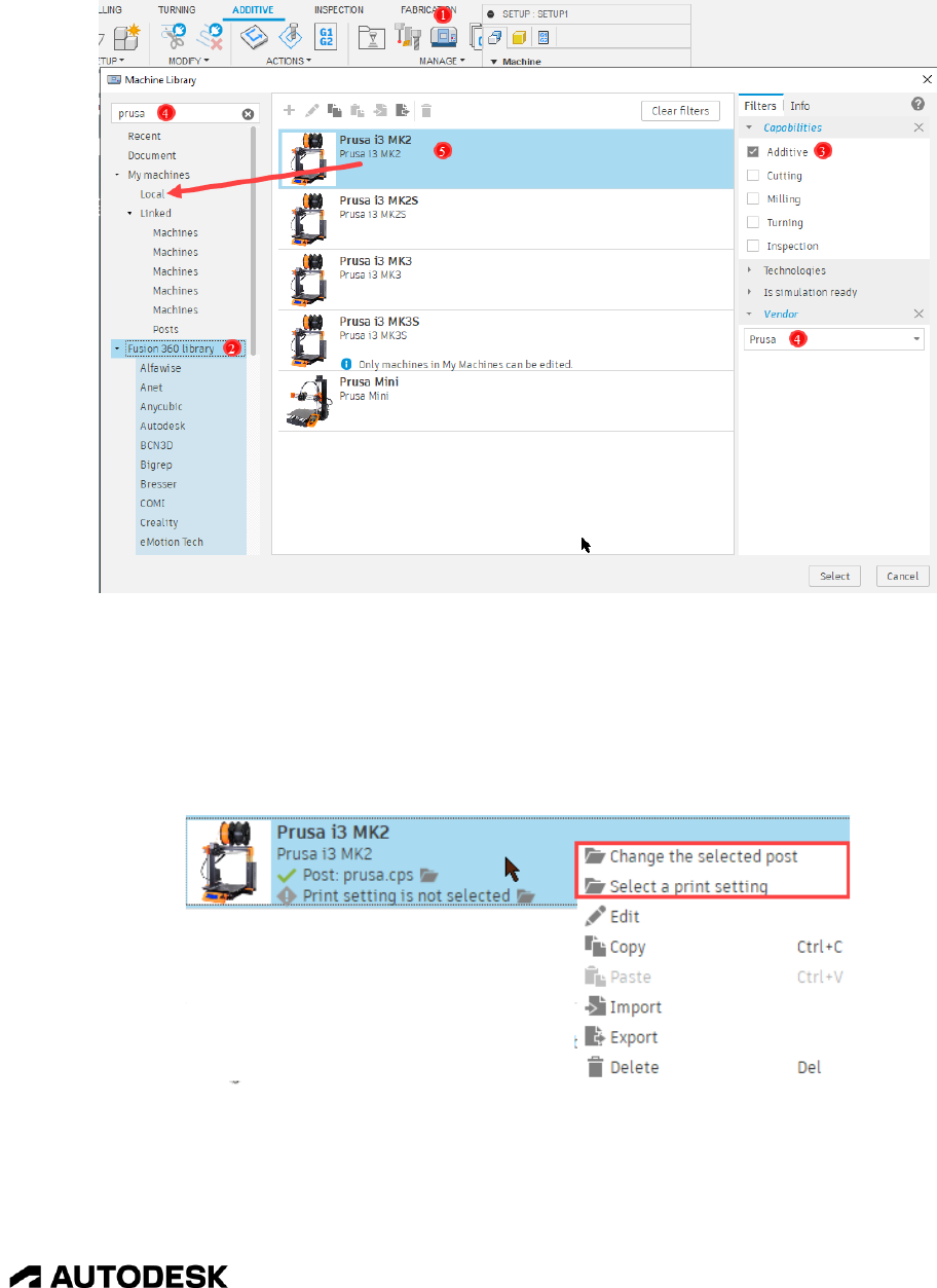
Additive Capabilities and Post Processors 11-265
CAM Post Processor Guide 2/2/24
using the Prusa i3 MK2 machine. You should drag this machine into your Local library for both
convenience and the ability to edit the machine.
Finding an Additive Machine and Storing in Your Local Library
Once you find your machine you may need to select the post processor and Print Settings that
correspond to this machine. The machines in the Fusion Library should all be assigned to the correct
post processor for each machine, so it is rare that you would need to change the post processor. If
necessary, you can select/change the post processor by right clicking on the Prusa i3 MK3 machine and
choosing Change the selected post.
Selecting/Changing the Post Processor and Setting the Print Settings

Additive Capabilities and Post Processors 11-266
CAM Post Processor Guide 2/2/24
The Post Library dialog will then be displayed. Select the Fusion library and check the Additive box to
display only the post processors supporting the Additive capabilities. You will want to select the Prusa
I3 MK2 machine. You will need to drag this post processor into to your Local library if you plan on
editing it.
Selecting the Post Processor
You can also create linked folders on your computer to store both the machines and post processors.
You do this by right clicking on the Linked menu and selecting the Link Folder menu. A browser will
be displayed allowing you to select a folder to place your machines/posts.
Selecting a Local Folder for The Machines and Post Processors
To select the Print Settings for the printer, right click on the Prusa i3 MK3 machine and choose Select a
print setting. This will bring up the Print Setting Library dialog allowing you to either select an existing
print setting or creating a custom print setting. Print Settings must be stored in the Local library in order
to create or edit them.

Additive Capabilities and Post Processors 11-267
CAM Post Processor Guide 2/2/24
Selecting the Print Setting
Once the Print Setting is in your local library you can edit it by pressing the button. Press the to
create a new Print Setting, you will be prompted to select an existing Print Setting to use as the template
for the new Print Setting.

Additive Capabilities and Post Processors 11-268
CAM Post Processor Guide 2/2/24
Editing a Print Setting
11.1.2 Creating an Additive Setup
In the Fusion Keychain model you will notice that there is already a subtractive setup defined. For
machines that support both additive and subtractive machining you can define both types of operations
as long as they are in separate setups. The subtractive operations for these machines are exactly the same
as they would be for a purely subtractive (milling) machine. For this sample we will be ignoring the
subtractive setup and working with the additive only.
To create an Additive setup, press the Setup menu, change the Operation Type to Additive, and select the
configuration for your machine by pressing the Select… button under Machine.
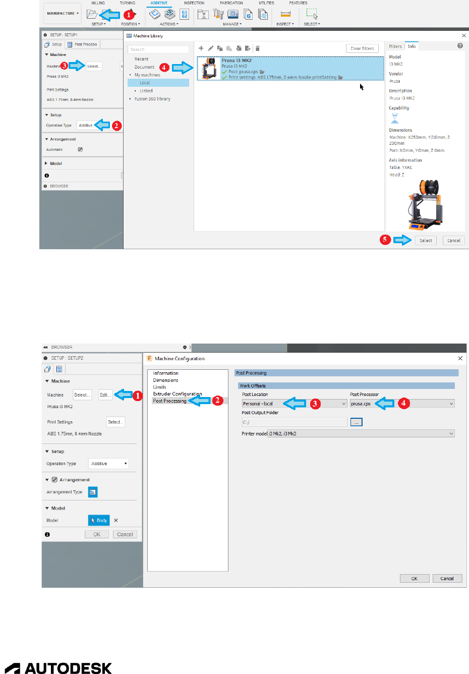
Additive Capabilities and Post Processors 11-269
CAM Post Processor Guide 2/2/24
Defining an Additive Setup
If you have not already assigned a post processor to this machine you will need to do so now. Do this
by pressing the Edit… button under the Machine prompt. The Machine Definition will display, change
the Post location to Personal – local, and select the prusa.cps post processor from the Post Processor
drop down menu.
Associating a Post Processor to a Machine Definition
You can select and/or edit the Print Settings directly from the Setup dialog when creating the Additive
Setup. The Print Settings are specific to the creation of the Additive toolpaths, with settings to modify

Additive Capabilities and Post Processors 11-270
CAM Post Processor Guide 2/2/24
the bed temperature, nozzle temperature, layer thickness, infill style, etc. You can also create your own
default print settings by giving them a new name.
Defining the Print Settings
After creating the Setup you should see a representation of the machine base and envelope with the part
located on it. Feel free to rename the new setup to Additive so you know that this is an additive
operation. If you were going to do both additive and subtractive operations in the same model, then you
will want to move the Additive setup above the Subtractive setup.

Additive Capabilities and Post Processors 11-271
CAM Post Processor Guide 2/2/24
Part Displayed on Machine
If the part is not in the location on the machine where you want it, you can easily reposition it using the
POSITION menus.
Positioning Menus
11.1.3 Creating and Simulating an Additive Operation
An Additive operation is automatically created when an Additive setup is created. You can see this
operation by expanding the Additive setup in the Browser. There can only be one Additive operation
per setup. You will need to generate the Additive Toolpath manually by selecting Generate from the
ACTIONS menus or by pressing Ctrl+G. This may take a while depending on the complexity of the
model.

Additive Capabilities and Post Processors 11-272
CAM Post Processor Guide 2/2/24
Generating the Additive Toolpath
To simulate the Additive toolpath press the Simulate button in the ACTIONS menus. Additive toolpaths
simulate in the same manner as Subtractive toolpaths, but it is recommended that you place the cursor
over the green slide bar at the bottom of the window, hold down the left mouse button, and move the
mouse to the left and right to visualize the Additive process.
Simulating the Additive Toolpath

Additive Capabilities and Post Processors 11-273
CAM Post Processor Guide 2/2/24
11.2 Creating a New Machine Definition
When adding a new Additive post processor you will need to create a corresponding Machine
Definition. You do this by copying an existing Machine Definition into your Local library by opening
the Machine Library dialog, selecting the Machine Definition you want to copy, and then pasting it into
your Local folder.
Copying a Machine Definition
Once you create a copy of the Machine Definition in your Local folder you will need to edit it and
describe your machine. Be sure to give it a unique name and description and go through all sections to
properly define the machine.
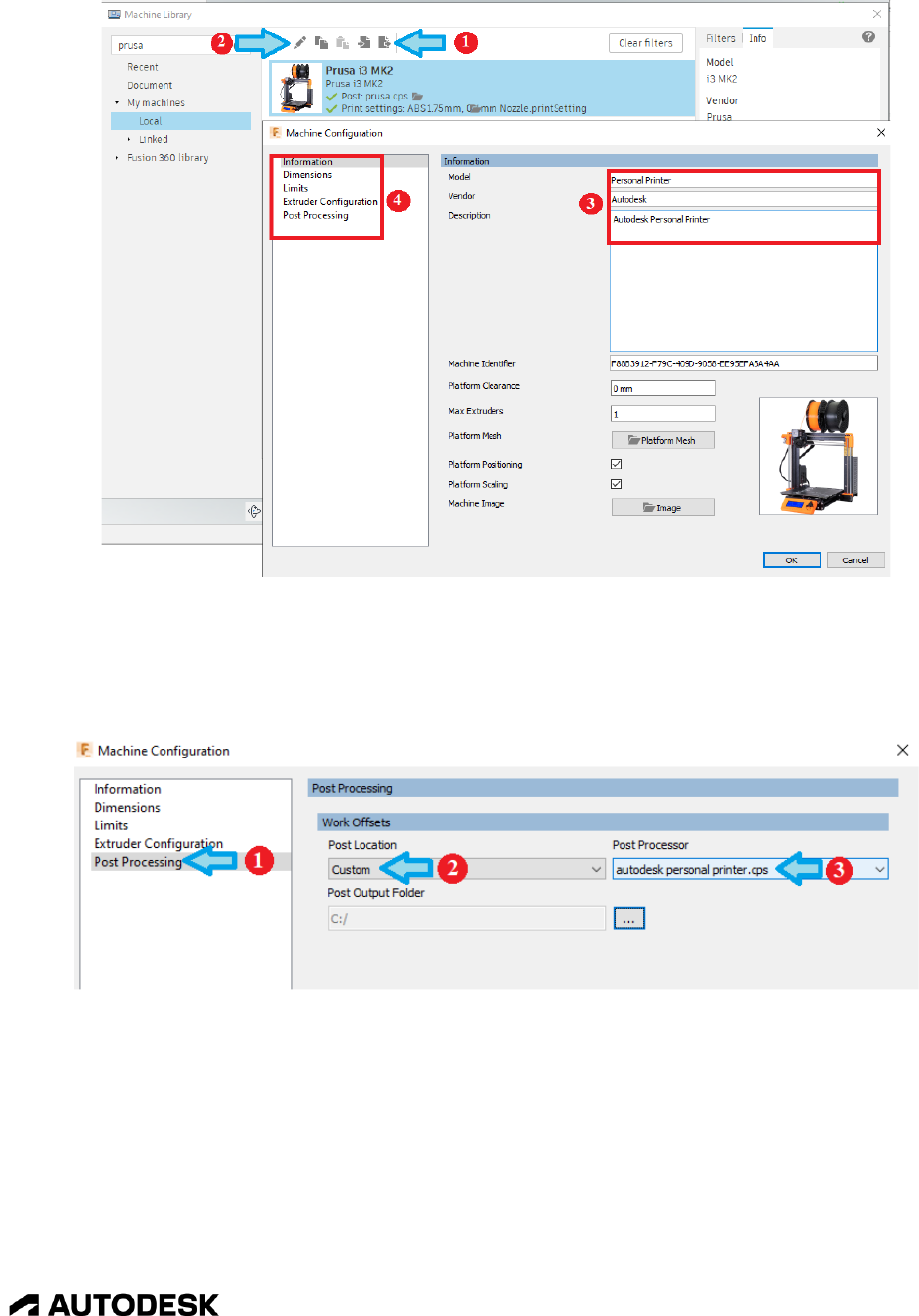
Additive Capabilities and Post Processors 11-274
CAM Post Processor Guide 2/2/24
Duplicating and Editing the Machine Definition
After creating your Machine Definition you will need to copy a seed post into a local folder, for example
prusa.cps, and give it a meaningful name. You can then assign this post processor to your machine.
You can also select the default output folder for your G-code files when posting.
Assigning a Post Processor to Your Additive Machine
You are now ready to edit your post processor.
11.3 Additive Common Properties
The additive post processors have properties that are common to most of them. These properties are
listed in the following table.

Additive Capabilities and Post Processors 11-275
CAM Post Processor Guide 2/2/24
Title
Property
Description
Relative extrusion mode
relativeExtrusion
Selects between an absolute or relative extrusion mode.
Trigger
_trigger
Specifies the method used to trigger a change of
extruder temperature. It can be disabled or controlled
by the Z-height or layer number.
Trigger Value
_triggerValue
Specifies the Z-height difference or layer number
increment to trigger an extruder temperature change.
Start Temperature
tempStart
The starting temperature in Celsius for the extruder,
overrides the starting temperature in the Print Settings.
Temperature Interval
tempInterval
The degrees in Celsius to increase the temperature of
the extruder for each trigger event.
Common Additive Properties
The Temperature Tower properties are typically used to test new filaments in order to identify the best
printing temperatures. These properties are listed in the Temperature Tower group.
11.4 Additive Variables
There are variables that are specific to Additive machines. These variables are either globally defined or
are accessed through function calls. The following table lists the variables available for Additive
machines.
Variable
Description
bedTemp
Temperature of bed.
commands
Post processor defined variable that defines the codes that are output for
additive commands.
Extruder
An unnamed object that contains the extruder definition. This object is
obtained by calling the getExtruder function.
layerCount
Number of printed layers for entire printing operation.
machineConfiguration
The machine configuration definition.
numberOfExtruders
Number of extruders used.
partCount
Number of bodies created during printing.
printTime
The amount of time the print should take.
settings
Post processor defined variable that defines settings specific to additive
machines.
Global Additive Variables
The post processor defined variables are defined in the getPrinterGeometry function from the
machineConfiguration settings and are typically in all Additive post processors.
11.4.1 The machineConfiguration Object
The machineConfiguration object is standard between all machine types, milling, turning, additive, etc.
machineConfiguration settings are always referenced using a function. The variables returned from the
functions are described in the following table.

Additive Capabilities and Post Processors 11-276
CAM Post Processor Guide 2/2/24
MachineConfiguration Function
Description
getCenterPositionX(id)
The center of the printer table in X.
getCenterPositionY(id)
The center of the printer table in Y.
getCenterPositionZ(id)
The center of the printer table in Z.
getExtruderOffsetX(id)
The offset in X from the reference extruder.
getExtruderOffsetY(id)
The offset in Y from the reference extruder.
getExtruderOffsetZ(id)
The offset in Z from the reference extruder.
getVendor()
Th manufacturer of the printer.
getModel()
The model type of the printer.
getNumberExtruders()
Number of defined extruders.
getWidth()
The width of the machine in X.
getDepth()
The depth of the machine in Y.
getHeight()
The height of the machine in z.
machineConfiguration Functions used for Additive
11.4.2 The Extruder Object
There is not really a named Extruder object, meaning you cannot use the new Extruder syntax to create
an object as you would a Vector, but there is the getExtruder function that will return an unnamed object
that has extruder specific variables. Each extruder can be referenced by passing the extruder number to
the getExtruder function.
var totalLength = getExtruder(1).extrusionLength;
Get the Total Length of Material Used for Extruder 1
The following table defines the variables accessible using the getExtruder function
Extruder Variable
Description
extrusionLength
Total length of material used for this extruder
during printing.
filamentDiameter
The diameter of the filament material.
materialName
The name of the material used for the extruder.
nozzleDiameter
The diameter of the extruder nozzle.
temperature
The temperature setting for the extruder.
Extruder Variables
11.4.3 The commands Object
The commands object is defined in the post processor and defines the output codes for common additive
commands. Define the proper code to be output for each command in this definition. Some of the
commands may have specifiers that define subcommands, such as on and off for fan. The following
table lists the commands supported by the library additive post processors.

Additive Capabilities and Post Processors 11-277
CAM Post Processor Guide 2/2/24
The code values can be a formatted number or a text string. If a command does not exist for your
printer, then define the code as undefined.
// Specify the required commands for your printer below.
var commands = {
extruderChangeCommand : undefined, // command to change the extruder
setExtruderTemperature: mFormat.format(104), // command to set the extruder
temperature
waitExtruder : mFormat.format(109), // wait command for the extruder
temperature
setBedTemperature : mFormat.format(140), // set the bed temperature
waitBed : mFormat.format(190), // wait for the bed temperature
reportTemperatures : undefined, // report the temperatures to the printer
fan : {on:mFormat.format(106), off:mFormat.format(107)},
extrusionMode : {relative:mFormat.format(83),
absolute:mFormat.format(82)} // extrusion mode
};
commands Definition
commands Variable
Description
extruderChangeCommand
Command to change the extruder.
setExtruderTemperature
Command to set the extruder temperature.
waitExtruder
The wait command when setting the extruder
temperature.
setBedTemperature
Command to set the bed temperature.
waitBed
The wait command when setting the bed
temperature.
reportTemperatures
Command to report the temperatures to the
printer.
Fan
Commands to turn the fan on and off, defined
using the syntax {on:---, off:---}.
extrusionMode
Commands to select either relative or absolute
filament extrusion modes, defined using the
syntax {relative:---, absolute:---}.
The commands Object
11.4.4 The settings Object
The settings object is post processor defined and defines fixed settings that are not controlled by post
properties.
var settings = {
useG0 : true, // use G0 or G1 commands for rapid movements
maximumExtruderTemp: 260 // specifies the maximum extruder temperature
};
settings Definition
settings Variable
Description

Additive Capabilities and Post Processors 11-278
CAM Post Processor Guide 2/2/24
useG0
Specifies whether to use G0 (true) or G1 (false)
for rapid moves.
maximumExtruderTemp
Sets the maximum extruder temperature.
The settings Object
11.5 Additive Entry Functions
Additive post processors use most of the common Entry functions for Subtractive posts, with some
specialized Entry functions for Additive post processors only. Remember that Entry functions are called
from the post processor kernel based on the record type in the intermediate file, so this means that there
is a difference between Subtractive and Additive intermediate files.
The following table defines the unique or modified Entry Functions for Additive post processors. You
can reference the table in the subtractive Entry Functions section for a description of the common entry
functions.
Entry Function
Invoked When …
onAcceleration(travel, printing, retract)
Acceleration is changed in an additive pass.
onBedTemp(temp, wait)
Bed temperature change.
onCircularExtrude(_clockwise, _cx, _cy, _cz,
_x, _y, _z, _f, _e)
Additive circular pass.
onClose()
End of post processing.
onExtruderChange(id)
Change of extruders.
onExtruderTemp(temp, wait, id)
Extruder temperature change.
onExtrusionReset(length)
Resets the length of the extrusion material used.
onFanSpeed(speed, id)
Change of fan speed.
onJerk(x, y, z, e)
The axis jerk is changed in an additive pass.
onLayer(layer)
Change of layer level.
onMaxAcceleration(x, y, z, e)
Max axis acceleration is changed in an additive pass.
onOpen()
Post processor initialization.
onLinearExtrude(x, y, z, f, e)
Additive pass.
onParameter(string, value)
Each parameter setting.
onRapid(x, y, z)
Positioning Rapid move.
onSection()
Start of an operation.
Additive Entry Functions
Many of the entry functions will get their arguments and settings from either the Machine Definition or
Print Settings. These dialogs can be accessed by pressing the right mouse button when over the
Additive setup and selecting Edit.

Additive Capabilities and Post Processors 11-279
CAM Post Processor Guide 2/2/24
Editing the Setup
This will display the Setup dialog, where you can select to edit either the Machine Definition (described
in the previous section) or Print Settings. You can also display the Print Settings dialog by pressing the
Print Settings button in the Additive menus.
Editing the Print Settings
11.5.1 Global Section
The global section for an Additive post is consistent with the standard global section for Subtractive
posts, it contains the description of the post processor and machine, its capabilities, kernel settings,
property table, and global variables. The capabilities of the post must be set to
CAPABILITY_ADDITIVE.

Additive Capabilities and Post Processors 11-280
CAM Post Processor Guide 2/2/24
capabilities = CAPABILITY_ADDITIVE;
// capabilities = CAPABILITY_ADDITIVE | CAPABILITY _MILLING; // additive & subtractive
Setting the Post Processor Capabilities to Additive
The common global variables found in an Additive post are defined in the Additive Variables section.
11.5.2 onOpen
function onOpen()
The onOpen function is called at the start of post processing and is used to define settings and output
startup blocks. It usually varies from machine to machine.
1. Define settings
2. Output machine and program description
3. Output initial startup codes
Following is an example onOpen function.
function onOpen() {
setFormats(MM); // machine require input code in MM
// output machine and program description
if (typeof writeProgramHeader == "function") {
writeProgramHeader();
}
// output start of program codes
writeBlock(gFormat.format(unit == MM ? 21 : 20)); // set unit
writeBlock("M115 U3.0.10 ; tell printer latest fw version");
if (getProperty("printerModel") == "i3mk2mk3") {
writeBlock(gFormat.format(28), "W ; home all without mesh bed level");
} else if (getProperty("printerModel") == "mini") {
writeBlock(gFormat.format(28), "; home all without mesh bed level");
}
}
Example onOpen Function
11.5.3 onSection
function onSection() {
The onSection function is called at the start of each Additive operation and outputs the starting codes for
an Additive operation. It usually varies from machine to machine.
function onSection() {

Additive Capabilities and Post Processors 11-281
CAM Post Processor Guide 2/2/24
// probe bed after heating
if (getProperty("printerModel") == "i3mk2mk3") {
writeBlock(gFormat.format(80), "; mesh bed leveling");
} else if (getProperty("printerModel") == "mini") {
writeBlock(gFormat.format(29), "; mesh bed leveling");
}
// output start of operation codes
writeBlock(gFormat.format(92), eOutput.format(0));
writeBlock(gAbsIncModal.format(90)); // absolute spatial co-ordinates
writeBlock(getCode(getProperty("relativeExtrusion") ? commands.extrusionMode.relative :
commands.extrusionMode.absolute));
}
Sample onSection Function
11.5.4 onClose
function onClose() {
The onClose function is called at the end of the last operation. It is used to output the end-of-program
codes. It usually varies from machine to machine.
function onClose() {
// output end-of-program codes
writeBlock("G4 ; wait");
xOutput.reset();
yOutput.reset();
if (getProperty("printerModel") == "i3mk2mk3") {
writeBlock(gMotionModal.format(1), xOutput.format(0),
yOutput.format(toPreciseUnit(200, MM)), "; home X axis");
} else if (getProperty("printerModel") == "mini") {
writeBlock(gMotionModal.format(1), xOutput.format(0),
yOutput.format(toPreciseUnit(150, MM)), "; home X axis");
}
writeBlock(mFormat.format(84), "; disable motors");
}
Sample onClose Function
11.5.5 onBedTemp
function onBedTemp(temp, wait) {
Arguments
Description
temp
The bed temperature in Celsius.
wait
Set to true when the machine should wait for the bed to warm up.

Additive Capabilities and Post Processors 11-282
CAM Post Processor Guide 2/2/24
The onBedTemp function is called multiple times during a toolpath. At the start of the operation
onBedTemp is called with wait set to false to start heating the bed. It is called a second time prior to the
start of the toolpath with wait set to true so that the machine waits for it to reach the targeted
temperature. It will also be called at the end of the program to turn off the heating of the bed.
The maximum bed temperature is defined in the Limits tab when defining the Machine Definition in
Fusion. The onBedTemp function is common to most additive posts.
function onBedTemp(temp, wait) {
if (wait) {
writeBlock(getCode(commands.reportTemperatures));
writeBlock(getCode(commands.waitBed), sOutput.format(temp));
} else {
writeBlock(getCode(commands.setBedTemperature), sOutput.format(temp));
}
}
onBedTemp Function
11.5.6 onExtruderTemp
function onExtruderTemp(temp, wait, id) {
Arguments
Description
temp
The extruder temperature in Celsius.
wait
Set to true when the machine should wait for the extruder to warm up.
id
Extruder number to set the temperature for. The first extruder is 0.
The onExtruderTemp function is called multiple times during a toolpath. At the start of the operation
onExtruderTemp is called with wait set to false to start heating the extruder. It is called a second time
prior to the start of the toolpath with wait set to true so that the machine waits for it to reach the targeted
temperature. It will also be called at the end of the program to turn off the heating of the extruder.
The desired extruder temperature is defined in the Extruder tab of the Print Settings dialog. The
maximum extruder temperature is set in the Extruder Configuration tab when defining the Machine
Definition in Fusion. The onExtruderTemp function is common to most additive posts.
function onExtruderTemp(temp, wait, id) {
if (typeof executeTempTowerFeatures == "function" && getProperty("_trigger") != undefined) {
if (getProperty("_trigger") != "disabled" && (getCurrentPosition().z == 0)) {
temp = getProperty("tempStart"); // override temperature with the starting temperature
}
}
if (wait) {
writeBlock(getCode(commands.reportTemperatures));

Additive Capabilities and Post Processors 11-283
CAM Post Processor Guide 2/2/24
writeBlock(getCode(commands.waitExtruder), sOutput.format(temp), tFormat.format(id));
} else {
writeBlock(getCode(commands.setExtruderTemperature), sOutput.format(temp),
tFormat.format(id));
}
}
onExtruderTemp Function
11.5.7 onExtruderChange
function onExtruderChange(id) {
Arguments
Description
id
Extruder number to activate. The first extruder is 0.
The onExtruderChange function handles a switch between extruders, similar to a tool change in a
subtractive machine. The number of extruders is defined in the Information tab when defining the
Machine Definition in Fusion. The onExtruderChange function is common to most additive posts.
function onExtruderChange(id) {
if (id > machineConfiguration.getNumberExtruders()) {
error(subst(localize("This printer does not support the extruder '%1'."), integerFormat.format(id)));
return;
}
writeBlock(getCode(commands.extruderChangeCommand), tFormat.format(id));
activeExtruder = id;
forceXYZE();
}
Sample onExtruderChange Function
11.5.8 onExtrusionReset
function onExtrusionReset(length) {
Arguments
Description
length
Length of the additive material used for the active extruder.
The onExtrusionReset function will be called to reset the length of the used additive material when the
active extruder changes. At the beginning of the program it will be called with a value of 0 and when
switching between one extruder and another it will pass the length of additive material used for the
newly activated extruder. The onExtruderChange function is common to most additive posts.
function onExtrusionReset(length) {
if (getProperty("relativeExtrusion")) {
eOutput.format(0);

Additive Capabilities and Post Processors 11-284
CAM Post Processor Guide 2/2/24
eOutput.format(0);
}
eOutput.reset();
writeBlock(gFormat.format(92), eOutput.format(length));
}
onExtrusionReset Function
11.5.9 onFanSpeed
function onFanSpeed(speed, id) {
Arguments
Description
speed
The fan speed as a percentage of the default speed in the range of 0-255.
id
Extruder number to set the fan speed for, typically the active extruder.
The onFanSpeed function is used to turn on and off the fan used for cooling the extruded material. The
fan is controlled starting at the layer after the number of disabled layers defined in the Cooling tab of the
Print Settings dialog. The onFanSpeed function is common to most additive posts.
function onFanSpeed(speed, id) {
if (!commands.fan) {
return;
}
if (speed == 0) {
writeBlock(getCode(commands.fan.off));
} else {
writeBlock(getCode(commands.fan.on), sOutput.format(speed));
}
}
onFanSpeed Function
11.5.10 onAcceleration
function onAcceleration(travel, printing, retract) {
Arguments
Description
travel
The travel acceleration, used for positioning moves.
printing
Printing acceleration, used for extrusion moves.
retract
Retract acceleration, used for extruder retract moves.
The onAcceleration function is invoked when the acceleration changes in an Additive toolpath. The
acceleration values are provided in (velocity_change/seconds)².
// set the current acceleration rate for the move types

Additive Capabilities and Post Processors 11-285
CAM Post Processor Guide 2/2/24
function onAcceleration(travel, printing, retract) {
writeBlock(mFormat.format(204), "P" + integerFormat.format(printing), "T" +
integerFormat.format(travel), "R" + integerFormat.format(retract));
}
onAcceleration Function
11.5.11 onMaxAcceleration
function onMaxAcceleration(x, y, z, e) {
Arguments
Description
x
The maximum acceleration along X.
y
The maximum acceleration along Y.
z
The maximum acceleration along Z.
e
The maximum acceleration of the extrusion.
The onMaxAcceleration function is invoked when the maximum axis acceleration changes in an
Additive toolpath. The acceleration values are provided in (velocity_change/seconds)².
// set the maximum acceleration for each axes
function onMaxAcceleration(x, y, z, e) {
writeBlock(mFormat.format(201), "X" + integerFormat.format(x), "Y" +
integerFormat.format(y), "Z" + integerFormat.format(z), "E" + integerFormat.format(e));
}
onMaxAcceleration Function
11.5.12 onJerk
function onJerk(x, y, z, e) {
Arguments
Description
x
The X-axis jerk.
y
The Y-axis jerk.
z
The Z-axis jerk.
e
The extruder jerk.
The onJerk function is invoked when the axis jerk changes in an Additive toolpath. The jerk control
values are provided in velocity_jerk/seconds.
// jerk control
function onJerk(x, y, z, e) {
writeBlock(mFormat.format(205), "X" + integerFormat.format(x), "Y" + integerFormat.format(y),
"Z" + integerFormat.format(z), "E" + integerFormat.format(e));

Additive Capabilities and Post Processors 11-286
CAM Post Processor Guide 2/2/24
}
onJerk Function
11.5.13 onLayer
function onLayer(layer) {
Arguments
Description
Layer
Current layer being printed.
The onLayer function is called for every printed layer and passes in the active layer. It can be used to
output a comment prior to the toolpath for each layer and/or to increment a counter on the machine
control to show the printing progress. The onLayer function is common to most additive posts.
function onLayer(num) {
if (typeof executeTempTowerFeatures == "function") {
executeTempTowerFeatures(num);
}
writeComment("Layer : " + integerFormat.format(num) + " of " +
integerFormat.format(layerCount));
}
Sample onLayer Function
11.5.14 onParameter
function onParameter(name, value) {
Arguments
Description
name
Parameter name.
value
Value stored in the parameter.
The onParameter function behaves the same as it does in a Subtractive post processor, but there is one
parameter that is specific to Additive machines. This is the feedRate parameter that defines the travel
speed that the machine will move when positioning without extruding material and for extruder changes.
The onParameter function is common to all additive posts.
function onParameter(name, value) {
switch (name) {
case "feedRate":
rapidFeedrate = toPreciseUnit(value > highFeedrate ? highFeedrate : value, MM);
break;
}
}
onParameter Function

Additive Capabilities and Post Processors 11-287
CAM Post Processor Guide 2/2/24
11.5.15 onRapid
function onRapid(_x, _y, _z) {
Arguments
Description
_x, _y, _z
The tool position.
The onRapid function handles positioning moves, which do not extrude the additive material. The
output of the onRapid function usually outputs a single block for the positioning move. The onRapid
function is common to all additive posts.
var rapidFeedrate = highFeedrate;
function onRapid(_x, _y, _z) {
var x = xOutput.format(_x);
var y = yOutput.format(_y);
var z = zOutput.format(_z);
var f = feedOutput.format(rapidFeedrate);
if (x || y || z || f) {
writeBlock(gMotionModal.format(settings.useG0 ? 0 : 1), x, y, z, f);
feedOutput.reset();
}
}
onRapid Function
11.5.16 onLinearExtrude
function onLinearExtrude(_x, _y, _z, _f, _e) {
Arguments
Description
_x, _y, _z
The tool position.
_f
The feedrate.
_e
Length of additive material to extrude during the move.
The onLinearExtrude function handles linear moves that extrude the additive material. The tool
position, feedrate and length of material to extrude are passed as the arguments. The onLinearExtrude
function is common to all additive posts.
function onLinearExtrude(_x, _y, _z, _f, _e) {
var x = xOutput.format(_x);
var y = yOutput.format(_y);
var z = zOutput.format(_z);
var f = feedOutput.format(_f);
var e = eOutput.format(_e);
if (x || y || z || f || e) {
writeBlock(gMotionModal.format(1), x, y, z, f, e);

Additive Capabilities and Post Processors 11-288
CAM Post Processor Guide 2/2/24
}
}
onLinearExtrude Function
11.5.17 onCircularExtrude
function onCircularExtrude(_clockwise, _cx, _cy, _cz, _x, _y, _z, _f, _e) {
Argument
Description
_clockwise
Set to true if the circular direction is in the clockwise direction, false if
counter-clockwise.
_cx, _cy, _cz
Center coordinates of circle.
_x, _y, _z
Final point on circle
_f
The feedrate.
_e
Length of additive material to extrude during the move.
The onCircularExtrude function handles circular moves that extrude the additive material. The tool
circle parameters, position, feedrate and length of material to extrude are passed as the arguments. The
onCircularExtrude function is common to all additive posts.
function onCircularExtrude(_clockwise, _cx, _cy, _cz, _x, _y, _z, _f, _e) {
var x = xOutput.format(_x);
var y = yOutput.format(_y);
var z = zOutput.format(_z);
var f = feedOutput.format(_f);
var e = eOutput.format(_e);
var start = getCurrentPosition();
var i = iOutput.format(_cx - start.x, 0);
var j = jOutput.format(_cy - start.y, 0);
switch (getCircularPlane()) {
case PLANE_XY:
writeBlock(gMotionModal.format(_clockwise ? 2 : 3), x, y, i, j, f, e);
break;
default:
linearize(tolerance);
}
}
onCircularExtrude Function
11.6 Common Additive Functions
There are non-entry functions that are common to Additive post processors. Some of these are defined
in the post processor kernel and some in the post processor itself. The following sections describes these
functions.

Additive Capabilities and Post Processors 11-289
CAM Post Processor Guide 2/2/24
11.6.1 getExtruder
function getExtruder(id) {
Arguments
Description
id
Extruder number to get information about.
The getExtruder function returns the Extruder variable, which includes information about the specified
extruder. Unlike the entry functions where the extruder base is 0, in the getExtruder function the first
extruder is referenced as id=1, the second as id=2, etc.
writeComment("Material used: " + dimensionFormat.format(getExtruder(1).extrusionLength));
writeComment("Material name: " + getExtruder(1).materialName);
writeComment("Filament diameter: " + dimensionFormat.format(getExtruder(1).filamentDiameter));
writeComment("Nozzle diameter: " + dimensionFormat.format(getExtruder(1).nozzleDiameter));
Sample Calls to getExtruder
11.6.2 isAdditive
function isAdditive() {
Returns true if any of the operations in the part are Additive in nature.
11.6.3 executeTempTowerFeatures
function executeTempTowerFeatures(num) {
Arguments
Description
num
The event that triggered the need to change the temperature. It is set to 1 on
the first call and then successive numbers on the remaining calls.
The executeTempTowerFeatures function is defined in the post processor and sets the temperature based
on the event specified by num. The initial value is 1 and ascends by 1 in each successive call. The
executeTempTowerFeatures function is common to all additive posts that support Temperature Tower
features.
var nextTriggerValue;
var newTemperature;
var maximumExtruderTemp = 260;
function executeTempTowerFeatures(num) {
if (settings.maximumExtruderTemp != undefined) {
maximumExtruderTemp = settings.maximumExtruderTemp;
}
if (getProperty("_trigger") != "disabled") {
var multiplier = getProperty("_trigger") == "height" ? 100 : 1;
var currentValue = getProperty("_trigger") == "height" ?

Deposition Capabilities and Post Processors 12-290
CAM Post Processor Guide 2/2/24
xyzFormat.format(getCurrentPosition().z * 100) : (num - 1);
if (num == 1) { // initialize
nextTriggerValue = getProperty("_triggerValue") * multiplier;
newTemperature = getProperty("tempStart");
} else {
if (currentValue >= nextTriggerValue) {
newTemperature += getProperty("tempInterval");
nextTriggerValue += getProperty("_triggerValue") * multiplier;
if (newTemperature <= maximumExtruderTemp) {
onExtruderTemp(newTemperature, false, activeExtruder);
} else {
error(subst(
localize("Requested extruder temperature of '%1' exceeds the maximum value of '%2'."),
newTemperature, maximumExtruderTemp)
);
}
}
}
}
}
executeTempTowerFeatures Function
if (typeof executeTempTowerFeatures == "function") {
executeTempTowerFeatures(num);
}
Sample Calls to executeTempTowerFeatures
12 Deposition Capabilities and Post Processors
Another additive capability supported by Fusion and the post processor is multi-axis deposition, for
example Directed Energy Deposition (DED). This technology is used to build up a part feature using a
metal depositing method. This chapter discusses the basics of generating a deposition tool path, creating
output, and the details of a deposition post processor.
12.1 Getting Started
This section will give an overview of creating a Deposition tool path using the multi-axis Feature
Construction operation inside of Fusion. It will not go into great detail on all of the features of the
Deposition capabilities of Fusion, just enough to get you started on post processing.
You will of course need a model to start with. For the examples in this manual, we will use the Fusion
Keychain model provided as a CAM sample with your installation of Fusion. This model contains
subtractive manufacturing operations which can be combined with Additive manufacturing operations as
long as your machine supports both capabilities.

Deposition Capabilities and Post Processors 12-291
CAM Post Processor Guide 2/2/24
Sample Deposition Part
You will see the ADDITIVE tab on the MANUFACTURE ribbon. Selecting this tab will display the
Additive menus.
12.1.1 Finding a Machine
The first step in creating a Deposition tool path is to define the machine that you will be using. Unlike
Subtractive operations where the Machine Definition is optional, it is required for Deposition operations
since they are considered Additive operations. Pressing the Machine Library icon in the Additive menus
will display the Machine Library dialog. Select the Fusion Library menu and check the Additive box
under Capabilities and the DED box under Technologies. to list the available Deposition machines.
Fusion comes with a single DED machine. You should drag this machine into your Local library for
both convenience and the ability to edit the machine.

Deposition Capabilities and Post Processors 12-292
CAM Post Processor Guide 2/2/24
Finding a DED Machine and Storing in Your Local Library
Once you find your machine you will need to select the post processor that corresponds to this machine.
You can select/change the post processor by right clicking on the Autodesk Generic DED machine and
choosing Select a post.
Selecting/Changing the Post Processor
The Post Library dialog will then be displayed. Select the Fusion library and check the Additive box to
display only the post processors supporting the Additive capabilities. For training purposes, you will
select the Deposition sample post processor. This post processor is not a full post processor, but rather a

Deposition Capabilities and Post Processors 12-293
CAM Post Processor Guide 2/2/24
template used to modify an existing post processor to include Deposition support. The post modification
will be discussed later in this chapter.
Selecting the Post Processor
You can also create linked folders on your computer to store both the machines and post processors.
You do this by right clicking on the Linked menu and selecting the Link Folder menu. A browser will
be displayed allowing you to select a folder to place your machines/posts.
Selecting a Local Folder for The Machines and Post Processors
12.1.2 Creating an Additive Setup for Deposition
In the Fusion Keychain model you will notice that there is already a subtractive setup defined. For
machines that support both additive and subtractive machining you can define both types of operations
as long as they are in separate setups. The subtractive operations for these machines are exactly the same
as they would be for a purely subtractive (milling) machine. For this sample we will be ignoring the
subtractive setup and working with the additive only.
To create an Additive setup, press the Setup menu, change the Operation Type to Additive, and select the
configuration for your machine by pressing the Select… button under Machine.

Deposition Capabilities and Post Processors 12-294
CAM Post Processor Guide 2/2/24
Defining an Additive Setup
If you have not already assigned a post processor to this machine you will need to do so now. Do this
by pressing the Edit… button under the Machine prompt. The Machine Definition will display, select
the Post Processing menu, press the … button and then select the Deposition sample post processor.
Associating a Post Processor to a Machine Definition
Feel free to rename the new setup to Deposition so you know that this is a deposition operation. If you
are going to do both deposition and subtractive operations in the same model, then you will want to
move the Deposition setup above the Subtractive setup.

Deposition Capabilities and Post Processors 12-295
CAM Post Processor Guide 2/2/24
12.1.3 Creating and Simulating a Deposition Operation
The Deposition operation in Fusion is named Feature Construction and is located in the MULTI-AXIS
pulldown.
Creating a Deposition Operation
A proper tool should be selected for depositing the material. Fusion supports Electric Arc Wire, Laser
Powder, and Laser Wire Deposition tools. If you don’t already have deposition tools defined, you can
create one using the normal method for creating a tool by pressing the + menu in the Select Tool form.
Selecting/Defining a Deposition Tool
You will need to select the base the Feature being built lies on and the Feature itself. You can also
generate multi-axis deposition moves by specifying a Forward Tilt and/or a Sideways Tilt.

Deposition Capabilities and Post Processors 12-296
CAM Post Processor Guide 2/2/24
For this exercise you can select the bottom surface of the keychain as the Base and the body of the
keychain as the Feature. The remaining tabs/fields in the Feature Construction form are similar to other
milling operations.
Selecting/Defining the Base Plane and Body for Deposition
To simulate the Deposition toolpath press the Simulate button in the ACTIONS menus. Deposition
toolpaths simulate in the same manner as Subtractive toolpaths, but it is recommended that you place the
cursor over the green slide bar at the bottom of the window, hold down the left mouse button, and move
the mouse to the left and right to visualize the Deposition process.

Deposition Capabilities and Post Processors 12-297
CAM Post Processor Guide 2/2/24
Simulating the Deposition Toolpath
12.2 The Deposition Sample Post Processor
Unlike additive post processors, which are standalone and created for a specific machine, deposition
capabilities are typically added to existing subtractive post processors for machines that support both
subtractive and deposition operations. The Deposition Sample Post Processor contains the basic
deposition functionality that can be added to a subtractive post. It is designed so that you can easily
copy the required code from this post processor into a post processor that you want to add deposition
capabilities to. In itself, it does not create a valid NC program for any machine.
The sample deposition post processor is broken up into separate sections, the first being code that will be
placed into existing functions, new code to be added to your post processor, and code that is common to
all other post processors used to create the sample output.
12.3 Deposition Specific Functions
You can start the modification of your post processor by copying the deposition specific functions into
your post processor. This code is marked in the sample post processor as follows.
// Start of Deposition logic
...
// End of Deposition logic
Copy this Code to Your Post Processor

Deposition Capabilities and Post Processors 12-298
CAM Post Processor Guide 2/2/24
The following table describes the functions included in the deposition code that is being copied to your
post.
Function
Description
Requires Editing
setDepositionCommands()
Enable to keep deposition on during
transition moves, or disable it to turn
deposition off.
Yes
getProcessParameters()
Processes the deposition parameters and
properties related to deposition
operations and stores them in the
processParameters object for use in
other functions.
No
writeDepositionHeader(tool)
Writes out a header containing the
deposition settings per operation.
Maybe
writeProcessEquipmentCommands
(activate)
Writes out the commands to turn
deposition on or off as defined in the
setDepositionCommands function.
No
onLayer(index)
Entry function called when a new layer
is started. index specifies the layer. 0 is
the first layer, 1 the second, etc.
Maybe
onLayerEnd(index)
Entry function called when the current
layer is completed.
Maybe
onMovemeentDeposition(movement)
Called from the onMovement function.
It turns on or off the depending on the
movement type.
No
Deposition Specific Functions
12.3.1 Deposition Common Properties
The deposition functions have properties that are common between most depositing machines. These
properties are listed in the following table.
Title
Property
Description
Deposit during transitions
depositOnTransitions
Enable to keep deposition on during transition
moves, or disable it to turn deposition off.
Common Deposition Properties
12.3.2 Deposition Commands
The commands to control the deposition operations are defined in the setDepositionCommands function
and will need to be edited to output the correct codes for your machine. It contains the commands to
turn on and off the process equipment for Electric Arc Wire, Laser Powder, and Laser Wire tools.
case TOOL_DEPOSITING_ELECTRIC_ARC_WIRE:

Deposition Capabilities and Post Processors 12-299
CAM Post Processor Guide 2/2/24
// insert startup codes for electric arc wire here
commands = {
deposition : {on:mFormat.format(101), off:mFormat.format(103)},
processEquipment: {
on: [ // commands to turn on process equipment
formatWords(gFormat.format(90), formatComment("ABSOLUTE MODE")),
formatWords(gFormat.format(300), "F" + processParameter.gasFlowRate,
formatComment("SHIELD GAS FLOW RATE")),
formatWords(gFormat.format(301), "V" + processParameter.arcCurrent,
formatComment("ARC VOLTAGE")),
formatWords(gFormat.format(302), "A" + processParameter.arcVoltage,
formatComment("ARC CURRENT")),
formatWords(gFormat.format(303), "S" + processParameter.wireSpeed,
formatComment("WIRE SPEED")),
formatWords(mFormat.format(304), formatComment("PROCESS ON"))],
off: [ // commands to turn off process equipment
formatWords(mFormat.format(305), formatComment("PROCESS OFF")),
formatWords(gFormat.format(303), "S0", formatComment("WIRE STOP")),
formatWords(gFormat.format(300), "F0000", formatComment("GAS OFF"))]
}
};
break;
Commands to Turn On and Off Deposition
12.3.3 Modifying Existing Functions to Support Deposition
After copying the deposition specific code and making the needed modifications you will need to
modify existing functions in your post processor to support deposition operations.
Function
Modification
onSection
Add code to define the deposition commands, write the deposition
operation head, and enable the deposition operation.
onSectionEnd
Add code to disable the deposition operation.
onMovement
Add a call to onMovementDeposition for a deposition operation.
Modification of Existing Functions for Deposition Support
function onSection() {
// #### Add the code below into the onSection function of your postprocessor ####
if (isDepositionOperation()) {
setDepositionCommands(); // setup for deposition process parameters
writeDepositionHeader(tool);
writeProcessEquipmentCommands(true);
}
// Important note, make sure that you disable the spindle speed output for deposition
// operations in your postprocessor.

Deposition Capabilities and Post Processors 12-300
CAM Post Processor Guide 2/2/24
}
Enable a Deposition Operation in onSection
function onSectionEnd() {
// #### Add the code below into the onSectionEnd function of your postprocessor ####
if (isDepositionOperation()) {
writeProcessEquipmentCommands(false);
}
}
Disable a Deposition Operation in onSectionEnd
// #### If your postprocessor does not have the onMovement function, you have to add the
// entire function below. ####
function onMovement(movement) {
// #### Add the code below into the onMovement function of your postprocessor. ####
if (isDepositionOperation()) {
onMovementDeposition(movement);
}
}
Call onMovementDeposition from onMovement
Index
Index 301
Autodesk CAM Post Processor Guide 2/2/24
?
? conditional ..................................... 3-66
3
3+2 operations ................................. 3-57
A
accuracy ......................................... 7-209
Action ............................................ 6-202
activateMachine1-13, 5-137, 8-211, 8-216, 8-
224, 9-244
activatePolarMode ......................... 8-237
Additive .............11-263, 12-290, 12-293
Additive operation ....................... 11-271
allowedCircularPlanes .......... 5-93, 5-175
allowFeedPerRevolutionDrilling5-93, 5-189
allowHelicalMoves ....5-93, 5-175, 5-178
allowSpiralMoves5-93, 5-175, 5-178, 5-179
approach ....................................... 10-249
areDifferent .................................... 5-107
argument .......................................... 3-73
array ..................... 3-52, 3-54, 3-73, 3-74
Array Object Functions .................... 3-54
Autodesk Fusion Post Processor Utility2-24
B
bedTemp ...................................... 11-275
Benchmark parts .............................. 1-18
Benchmark Parts ..................... 2-41, 2-44
bookmarks ............................... 2-34, 2-35
booleans ........................................... 3-52
break ....................................... 3-65, 3-72
Built-in properties ............................ 5-97
C
CAM partners .................................. 1-17
capabilities ...............5-93, 9-243, 11-279
CAPABILITY_ADDITIVE ........ 11-279
case .................................................. 3-65
case sensitive ................................... 3-47
certificationLevel ............................. 5-93
checkGroup .................................... 5-152
circular interpolation ........... 5-173, 5-174
circular plane ........................ 5-93, 5-175
circularInputTolerance .......... 5-93, 5-175
circularMergeTolerance ........ 5-94, 5-175
circularOutputAccuracy ........ 5-94, 5-175
clearance plane ............................... 5-194
clockwise .......................... 5-173, 11-288
CNC Handbook ................................. 1-1
collected state ................................. 5-119
commands ....................... 11-275, 11-276
comment ............................... 3-47, 5-157
compensateToolLength .................. 8-212
conditional function ......................... 3-68
conditional statements ..................... 3-64
continue ............................................ 3-72
coolant ............................ 4-75, 5-132
coolants .......................................... 5-132
createAxis ................8-212, 8-221, 8-228
createFormat 5-106, 5-109, 5-110, 8-211
createIncrementalVariable ............. 5-114
createModal ................................... 5-114
createModalGroup ......................... 5-115
createOutputVariable .......... 5-110, 8-221
createReferenceVariable ................ 5-114
createVariable ..................... 5-114, 8-211
currentSection ................................ 5-146
cycle .................................. 5-181, 10-260
Cycle parameters ........................... 5-184
Cycle planes/heights ...................... 5-185
cycleType .............5-183, 10-247, 10-256
cyclic ................................... 8-221, 8-228
D
Date ................................................ 5-122
deactivatePolarMode ..................... 8-237
debug .............. 2-41, 5-191, 7-207, 7-209
Debugging ...................................... 7-206
debugMode ......................... 7-207, 7-209
default .............................................. 3-65
Deferred variables ............................ 3-60
DeferredVariables ............................ 3-60
defineMachine ............................... 8-212
defineWorkPlane ................ 5-137, 5-143
degrees ........................................... 8-211
Index
Index 302
Autodesk CAM Post Processor Guide 2/2/24
Degrees Per Minute ....................... 8-231
Deposition .................................... 12-290
description ........................................ 5-94
Diameter Offset ............................. 5-130
disable ............................................ 5-111
do/while ........................................... 3-71
doesToolPathFitWithinLimits ....... 5-141
download a post ................................. 1-3
drilling cycles ................................. 8-241
drillingSafeDistance ...................... 5-184
dump.cps ..................5-160, 6-202, 7-206
E
editor ................................1-8, 1-11, 2-24
else ................................................... 3-65
enableMachineRewinds ................. 8-215
entry function ................................. 7-206
Entry functions .................... 5-91, 11-278
Euler ............................................... 5-143
Euler Angle Order ............................ 5-137
Euler angles ................................... 5-136
eulerConvention ............................. 5-136
executeManualNC ......................... 6-200
executeTempTowerFeatures ........ 11-289
expanded cycles .................. 5-182, 5-183
expandManualNC .......................... 6-197
expression ............ 3-63, 3-67, 3-70, 3-74
expression operators ........................ 3-64
extension .......................................... 5-94
Extruder .......................... 11-275, 11-276
F
Feature Construction ....... 12-290, 12-295
Feedrate ............................. 5-173, 11-288
fixed settings ....................... 5-118, 5-119
for ............................................ 3-70, 3-72
Force tool change ........................... 5-130
forceABC ....................................... 5-193
forceAny ........................................ 5-193
forceFeed ....................................... 5-193
forceMultiAxisIndexing ................ 5-136
forceXYZ ....................................... 5-193
format5-106, 5-107, 5-110, 5-112, 5-115, 5-117
formatComment ............................. 5-158
FormatNumber .................... 5-107, 5-110
function ....... 3-49, 3-67, 3-72, 3-73, 3-74
fused filament fabrication ............ 11-263
G
G-code ................................................ 1-1
Geometry Probing ........................ 10-256
getABCByPreference ......... 5-139, 8-220
getCircularCenter ........................... 5-177
getCircularChordLength ................ 5-177
getCircularNormal ......................... 5-177
getCircularPlane ............................ 5-177
getCircularRadius .......................... 5-177
getCircularStartRadius ................... 5-177
getCircularSweep ........................... 5-177
getCommonCycle ............... 5-187, 8-241
getCoolantCodes ............... 5-133, 10-254
getCurrent ...................................... 5-112
getCurrentABC .............................. 8-220
getCurrentDirection ............ 5-139, 8-220
getCurrentPosition ......................... 5-177
getCurrentToolAxis ....................... 8-220
getDirection ................................... 8-220
getEuler2 ............................. 5-137, 5-143
getExtruder ..................... 11-276, 11-289
getFinalToolAxisABC ................... 8-220
getFirstTool ......................... 5-131, 5-152
getFramePosition ........................... 5-145
getGlobalFinalToolAxis ................ 8-220
getGlobalInitialToolAxis ............... 8-220
getGlobalParameter ....................... 5-161
getHeadAttachPoint ....................... 9-245
getHeaderDate ............................... 5-122
getHeaderVersion .......................... 5-122
getHelicalDistance ......................... 5-177
getHelicalOffset ............................. 5-177
getHelicalPitch ............................... 5-178
getId ............................................... 5-147
getInitialToolAxisABC ....... 8-218, 8-220
getLinearMoveLength ........ 8-235, 8-237
getMinimumValue ......................... 5-107
getMultiAxisMoveLength ............. 8-235
getNextSection ............................... 5-153
getNextTool ........................ 5-131, 5-151
getNumberOfSections5-125, 5-147, 5-161
getOptimizedPosition .................... 8-224
getOptimizedTCPMode ................. 8-220
getParameter .................................. 5-160
Index
Index 303
Autodesk CAM Post Processor Guide 2/2/24
getPartAttachPoint ......................... 9-244
getPolarPosition ............................. 8-237
getPositionU ....................... 5-178, 5-180
getProbingArguments .................. 10-250
getProperty ......................... 5-100, 5-103
getRadialMoveLength ................... 8-235
getRadialToolTipMoveLength ...... 8-235
getResultingValue ................. 3-69, 5-112
getSection ................5-125, 5-146, 5-161
getSetting ......................................... 4-91
getTableAttachPoint ...................... 9-245
getTool ........................................... 5-125
getToolList ..................................... 5-123
getWorkPlaneMachineABC 5-138, 5-143
gFeedModeModal .......................... 8-233
Global Section .................... 5-93, 11-279
global variable .............3-49, 5-93, 5-119
gRotationModal ........................... 10-252
groupDefinitions ................... 5-98, 5-102
H
hasGlobalParameter ....................... 5-161
hasParameter .................................. 5-160
helical interpolation ............ 5-177, 5-178
helical move ..................................... 5-93
high feedrate ....................... 5-165, 5-169
highFeedMapping ............................ 5-94
highFeedrate .................................... 5-94
home position ................................. 5-194
HSM Post Processor Editor ............. 3-48
I
if 3-64, 3-66
incremental .................................... 5-114
indentation ....................................... 3-48
initalizeSmoothing ........................... 4-79
Initial Position ..................... 5-130, 5-145
insertToolCall ..................... 5-130, 5-153
Inspect Surface ............................. 10-258
intermediate file .................... 1-1, 11-278
Inverse Time ....................... 8-231, 8-237
inverseTimeOutput ........................ 8-233
invokeOnCircular .......................... 5-180
invokeOnLinear ............................. 5-168
invokeOnLinear5D ........................ 5-172
invokeOnRapid .............................. 5-167
invokeOnRapid5D ......................... 5-170
is3D ................................................ 8-221
isAdditive ..................................... 11-289
isAxialCenterDrilling .................... 5-149
isDepositionOperation ................... 5-151
isDrillingCycle ............................... 5-148
isFirstCyclePoint ............................ 5-187
isFullCircle .................................... 5-178
isHelical ......................................... 5-178
isInspectionOperation .................... 5-150
isLastCyclePoint ............................ 5-187
isLastSection .................................. 5-153
isMillingCycle ............................... 5-150
isMultiAxis .................................... 5-143
isMultiAxisConfiguration ... 5-143, 8-220
isNewWorkOffset .......................... 5-148
isNewWorkPlane ................ 5-127, 5-148
isOptimizedForMachine ..... 8-218, 8-220
isPolarModeActive ........................ 8-237
isProbeOperation ........................... 5-150
isProbingCycle ............................... 5-187
isSignificant ................................... 5-108
isSpindleSpeedDifferent ................ 5-148
isSpiral ........................................... 5-178
isTappingCycle .............................. 5-149
isToolChangeNeeded .......... 5-127, 5-147
J
JavaScript ......................................... 3-46
K
kernel settings .................................. 5-93
L
Laser ................................................ 1-23
layerCount .................................... 11-275
legal .................................................. 5-94
Length Offset ................................. 5-130
linear scale ..................................... 8-221
linearize .......................................... 5-178
linked folders .................. 11-266, 12-293
local variables .................................. 3-49
log .................................................. 7-209
longDescription .............................. 5-122
looping statements ........................... 3-69
Index
Index 304
Autodesk CAM Post Processor Guide 2/2/24
M
machine configuration ................... 8-211
Machine Definition1-7, 1-13, 5-96, 5-101, 5-
123, 5-133, 5-141, 8-212, 9-242, 9-244, 11-
264, 11-273, 12-291
machine simulation ........................ 9-243
machineAngles ........................ 4-82
machineConfiguration5-122, 9-244, 11-275
machining plane ............................. 5-181
Manual NC ..................................... 6-202
Manual NC command5-119, 5-154, 5-156, 5-
157, 5-159, 5-160
Manual NC Command ................... 6-196
mapToWCS ..................................... 5-94
mapWorkOrigin ............................... 5-94
Math Object ..................................... 3-50
Matrix .............................................. 3-57
Matrix Object Assignments ............. 3-57
Matrix Object Attributes .................. 3-58
Matrix Object Functions .................. 3-59
matrixes .......................................... 7-208
maximumCircularRadius ...... 5-94, 5-175
maximumCircularSweep5-95, 5-119, 5-176
maximumSequenceNumber ............. 4-90
maximumSpindleRPM .................... 4-91
maximumToolDiameterOffset ......... 4-91
maximumToolLengthOffset ............ 4-91
maximumToolNumber .................... 4-91
mill/turn ........................................... 1-21
milling .............................................. 1-20
minimumChordLength ......... 5-95, 5-176
minimumCircularRadius ....... 5-95, 5-176
minimumCircularSweep ....... 5-95, 5-176
minimumRevision ............................ 5-95
Modal Groups ................................ 5-115
ModalGroup ................................... 5-116
model origin ..................................... 5-94
MoveLength ................................... 8-235
movement ...................................... 5-165
moveToSafeRetractPosition .......... 8-230
multi-axis1-17, 3-57, 5-169, 5-171, 8-210
multi-axis ....................................... 5-120
Multi-Axis Feedrates .......... 8-231, 8-235
N
NC file extension ............................. 5-94
NC Program ............................ 1-11, 5-96
next tool ......................................... 5-131
number .................................... 3-49, 3-74
Number Objects ............................... 3-49
numberOfExtruders ..................... 11-275
O
object ....................................... 3-54, 3-74
offset tables and heads ................... 8-221
onAcceleration ............................. 11-284
onBedTemp .................................. 11-282
onchange ........................................ 5-111
onCircular ................5-163, 5-173, 5-180
onCircularExtrude ........................ 11-288
onClose ..................5-154, 5-155, 11-281
onCommand5-156, 5-163, 5-183, 6-198, 6-201
onComment ..............5-157, 6-198, 7-210
onCycle .......................................... 5-181
onCycleEnd ....................... 5-190, 10-251
onCyclePoint5-181, 8-241, 10-247, 10-250, 10-
260
onDwell ............................... 5-159, 6-198
onExtruderChange ....................... 11-283
onExtruderTemp .......................... 11-282
onExtrusionReset ......................... 11-283
onFanSpeed .................................. 11-284
onImpliedCommand ........... 5-155, 5-157
onJerk ........................................... 11-285
onLayer ........................................ 11-286
onLinear ....... 5-163, 5-166, 5-167, 5-168
onLinear5D5-171, 5-173, 8-218, 8-233, 8-241
onLinearExtrude .......................... 11-287
onManualNC ............6-197, 6-199, 6-200
onMaxAcceleration ...................... 11-285
onMovement .................................. 5-165
onMoveToSafeRetractPosition5-92, 8-229
onOpen ...................5-119, 8-211, 11-280
onOrientateSpindle ........................ 5-163
onParameter5-159, 5-162, 6-198, 6-202, 10-
253, 11-286
onPassThrough ................... 6-199, 6-205
onRadiusCompensation ................. 5-163
onRapid ...... 5-163, 5-165, 5-167, 11-287
onRapid5D ... 5-169, 5-170, 8-218, 8-241
onReturnFromSafeRetractPosition5-92, 8-229
onRewindMachineEntry ....... 5-92, 8-229
Index
Index 305
Autodesk CAM Post Processor Guide 2/2/24
onRotateAxes ........................ 5-92, 8-229
onSection ...............5-127, 5-154, 11-280
onSectionEnd5-127, 5-128, 5-153, 5-154, 10-
254
onSpindleSpeed ............................. 5-163
onTerminate ................................... 5-155
Operation Comment ....................... 5-128
Operation Notes ............................... 5-129
Operation properties ...................... 5-100
Operation Properties ........................ 1-13
operators .......................................... 3-63
optimize3DPositionsByMachine4-85, 5-142
optimizeMachineAngles2 .............. 8-216
optimizeMachineAnglesByMachine8-216
optional skip ................................... 5-191
output units ...................................... 5-95
outputToolDiameterOffset ............... 4-91
outputToolLengthCompensation ..... 4-90
outputToolLengthOffset .................. 4-90
OutputVariable ................... 5-110, 5-111
P
parametric feedrates ....................... 5-165
parametricFeeds ................... 4-80
parseFloat ......................................... 3-50
parseInt ............................................ 3-50
parseSpatialProperties .................... 5-104
partCount ..................................... 11-275
pendingRadiusCompensation ........ 5-164
permittedCommentChars ............... 5-158
pivot point ...................................... 8-222
Plasma .............................................. 1-23
Polar interpolation ......................... 8-235
polarDirection ............................... 8-238
post kernel ........................................ 3-48
Post Library ....................................... 1-2
post processor2-41, 11-265, 11-269, 11-274, 12-
292, 12-294
post processor documentation .......... 3-47
Post Processor Forum ............... 1-2, 1-17
Post Processor Ideas ................. 1-2, 1-17
Post Properties ................................. 2-42
preloadTool .................................... 5-131
Print Settings ......11-265, 11-269, 11-279
printTime ..................................... 11-275
probeMultipleFeatures ................. 10-257
probeWorkOffset ........................... 5-151
Probing ..... 1-23, 10-245, 10-256, 10-258
program comment .......................... 5-120
program name ...... 1-8, 1-11, 5-95, 5-120
programComment .......................... 5-121
programName ................................ 5-121
programNameIsInteger ......... 5-95, 5-120
properties ........... 1-8, 1-11, 5-97, 11-274
Property Table . 3-54, 5-96, 5-118, 5-119
protecedProbeMove ..................... 10-250
R
radians ................................... 3-50, 8-211
radius compensation5-165, 5-167, 5-171, 5-173
range ................................... 8-221, 8-228
rapid ................................................. 5-94
real value .......................................... 3-69
repositionToCycleClearance .......... 5-187
retract ................ 4-79, 5-128, 5-145
return ....................................... 3-73, 3-74
rotary axes ...................................... 8-211
Rotary Axis Order .......................... 8-213
rotary scale ..................................... 8-221
RS-274D Sample Multi-axis Post Processor ... 8-
210
S
safePositionMethod ............ 4-80
section ............................................ 5-146
seed post ........................................... 1-18
sequence number ........................... 5-191
setCoolant ...................................... 5-133
setCurrentABC .............................. 8-221
setCurrentPositionAndDirection .... 8-237
setMachineConfiguration .............. 8-216
setMultiAxisFeedrate ..................... 8-215
setPolarFeedMode ......................... 8-238
setPolarMode ................................. 8-237
setPrefix ......................................... 5-117
setProbeAngle .............................. 10-250
setProbeAngleMethod ................. 10-250
setProperty ..................................... 5-104
setSingularity ................................. 8-226
setSmoothing .......................... 4-78, 4-79
setSuffix ......................................... 5-117
settings ...................4-75, 11-275, 11-277
Index
Index 306
Autodesk CAM Post Processor Guide 2/2/24
setToolLength ................................ 8-223
setup .....................5-162, 11-268, 12-293
setVirtualTooltip ................. 8-214, 8-224
setWordSeparator ............... 5-120, 5-191
setWorkPlane ................................. 5-144
setWriteInvocations .............. 2-41, 7-207
setWriteStack ........................ 2-41, 7-208
showNotes ............................ 5-124, 5-129
simulate ........................... 11-272, 12-296
singleLineCoolant .......................... 5-132
singularity ...................................... 8-226
smoothing .................................. 4-76
spatial ............................................... 3-50
spindle codes .................................. 5-132
spindleOrientation .......................... 5-184
spindleSpeedDwell ........................ 5-184
spiral interpolation .............. 5-178, 5-179
spiral move ....................................... 5-93
stock transfer .................................... 1-22
strategy ....................5-102, 5-152, 5-153
string ..............................3-47, 3-51, 3-74
String Object Functions ................... 3-52
subprograms ............................. 4-86
supportsInverseTimeFeed ................ 4-90
supportsOptionalBlocks ................... 4-90
supportsRadiusCompemsation ........ 4-90
supportsTCP .................................... 4-90
supportsToolVectorOutput .............. 4-90
switch ...................................... 3-65, 3-72
T
tapping cycles ................................ 5-189
TCP ................................................ 8-231
Template ........................................ 6-205
toDeg ................................................ 3-50
tolerance .....................5-95, 5-176, 5-178
tool axis ....................5-169, 5-171, 8-226
Tool change ................................... 5-130
tool length offset ............................ 5-145
toolZrange ...................................... 5-152
toolZRange .................................... 5-131
toPreciseUnit ......................... 3-50, 5-192
toRad ................................................ 3-50
toUnit ............................................... 3-51
try/catch ........................................... 3-68
typeof ............................................... 3-67
U
undefined ......................................... 3-48
unit ..................... 1-8, 1-11, 5-120, 5-126
unwind ......................................... 4-81
unwindABC ..................................... 4-82
useABCPrepositioning4-85, 5-136
useFilesForSubprograms ................. 4-88
useMultiAxisFeatures .................... 5-136
useParametricFeed ............... 4-81
usePolarMode ................................ 8-238
User Settings .................................... 2-27
useSmoothing .................................. 4-78
useSubroutines ...................... 4-88
useTiltedWorkPlane ............ 4-85
V
validate ............................................. 3-69
var .................................................... 3-48
variable ... 3-48, 3-63, 3-67, 3-73, 11-275
Vector .............................................. 3-55
Vector Attributes ............................. 3-55
Vector Object Functions .................. 3-56
vectors ............................................ 7-208
virtual tool tip ................................ 8-224
Visual Studio Code .......................... 2-24
W
Waterjet ............................................ 1-23
WCS ...........................5-94, 5-133, 5-153
WCS Probing ............................... 10-245
wcsDefinitions ............................... 5-133
while ................................................ 3-71
Work Coordinate System5-127, 5-133, 10-245
Work Plane5-94, 5-127, 5-135, 5-138, 5-143, 5-
153
workOffset ..................................... 5-126
workPlaneMethod ................... 4-83
writeBlock ...................................... 5-191
writeComment5-121, 5-122, 5-158, 7-210
writeDebug .................................... 7-210
writeln ................................. 5-191, 7-209
writeNotes ........................... 5-125, 5-160
writeRetract .. 5-128, 5-155, 5-194, 8-215
writeSectionNotes .......................... 5-130
writeSetupNotes ............................. 5-124
Index
Index 307
Autodesk CAM Post Processor Guide 2/2/24
