
ACC
Advanced Commercial Controller
Owner’s Manual, Installation, and Programming Instructions for
ACC and ACC Decoder Controllers
■
ACC-1200 12 Station Controller, 42 Station
Capacity, Metal Cabinet
■ ACC-1200-PP 12 Station Controller, 42
Station Capacity, Plastic Pedestal
■ ACC-99D 2-Wire Decoder Controller with
99 Station Capacity, Metal Cabinet
■ ACC-99D-PP 2-Wire Decoder Controller
with 99 Station Capacity, Plastic Pedestal
Table of ConTenTs
ACC INTERFACE AND KEY COMPONENTS 2
WIRING COMPARTMENT INTERIOR 3
METAL CABINET, WALL MOUNT INSTALLATION 4
CONNECTING AC MAIN POWER, WALL MOUNT CABINET 5
METAL CABINET OPTIONAL PEDESTAL INSTALLATION 6
Connecting the Metal Pedestal Main AC Power 6
PLASTIC PEDESTAL INSTALLATION 6
CONCRETE BASE INSTALLATION 7
CONNECTING PLASTIC PEDESTAL AC MAIN POWER 8
120 VAC Connection 8
230 VAC Connection 8
CONNECTING EARTH GROUND (ALL CONFIGURATIONS) 10
INSTALLING STATION MODULES 11
Output Modules (ACM600, AGM600) 11
Connecting the Valve Wires 12
Decoder Output Module (ADM99) 12
Connecting Decoder Output Path Wires 12
KEY CONNECTIONS 13
24 VAC TEST TERMINAL 14
CONNECTING THE MASTER VALVE(S) AND/OR PUMP START RELAY(S) 14
CONNECTING A RAIN OR FREEZE SHUT OFF DEVICE 14
CONNECTING THE HUNTER FLOW SENSOR 15
CONNECTING OTHER FLOW SENSORS 16
ICR REMOTE CONTROL 16
Multiple Stations simultaneously 16
CONNECTING TO IMMS 17
Dial-up telephone (ACC-COM-POTS) 17
Cellular/GSM (ACC-COM-GSM, GSM-E) 18
UHF Radio 18
POWER FAILURES 18
QUICK START 18
CONTROLLER PROGRAMMING AND OPERATION 19
Using the Information Button 19
Setting Current Date and Time 20
Setting Program Start Times 20
To Set Program Start Times 20
Stacked Start Times 20
Overlapping Start Times 20
Multiple Start Times 21
No-Water Window 21
Setting Station Run Time Duration 21
Changing Seasonal Adjust 22
Using the Global Setting 22
Using a Program Specific Setting (set Season Adjust by Program) 22
Timed Delay between Stations 22
Setting Days to Water 22
Set Days to Water 22
Day of the Week Watering 23
Interval Watering 23
Odd/Even Watering 23
Setting Pump and Master Valve Operation 23
Set Pump and Master Valve Operation 24
Changing from Normally Closed to Normally On and Location of P/MV 24
Setting Station Cycle and Soak Durations 24
Set Station Cycle and Soak Durations 24
Cycle and Soak Summary 24
SETTING FLOW MONITORING 25
Step 1: Select The Flow Sensor 25
Step 2: Viewing Real-Time Flow 26
Step 3: Preparing for Flow Learning 27
Step 4: Learning the Flow 27
Step 5: Review And Edit Flow 28
Flow Alarms 28
Alarm Logs 29
Tips on Flow Alarms 30
SETTING CLIK™ SENSOR OPERATION 30
Set Sensor Operation 31
SENSOR ALARMS (CLIK SENSORS SEN 1–4 ONLY) 32
Clear Message 32
Sensor Locations 33
Sensor Locations 35
SETTING PROGRAM OVERLAP OPTIONS 36
Option One: Stack or Overlap 36
Option Two: SmartStack™ 36
Option Three: SSG/SmartStack™ 36
Set Station & Program Names 37
Assign Contact Information 37
DATA HISTORY 38
Name a Program (Up to 12 Characters and Spaces) 38
Name a Station (Up to 12 Characters and Spaces) 38
View Flow Totals 38
View Alarm Logs 38
View Controller Logs 39
View Station Logs 39
Advanced Features 39
View Version and Station Size 40
COMMON ALARM (ATTENTION) MESSAGES 41
Overcurrent 41
Overflow 42
Power Outage/Power Restored 43
Underflow 43
EXTENDED FEATURES 43
Contrast Adjustment 43
No Water Window 44
To set a No Water Window 44
No Water Window rules 44
Delay Between Stations 45
To set a Delay 45
P/MV Style (Normally Closed/Normally On) 45
To change the Normal condition of P/M outputs 46
Setting the Flow Sensor Size and Type 46
Additional settings for OTHER 47
SSG (Simultaneous Station Group) Setup 47
EDIT AN SSG 48
ADDING AN SSG 49
DELETING AN SSG 49
SSG FLOW DATA 49
SSG Rules 49
Custom Manual Program Setup 50
Custom Manual Rules 50
Start a Custom Manual 51
Test Program 51
Run a Test Program 51
Easy Retrieve™ Backup 52
ONE TOUCH MANUAL START 53
MANUAL OPERATION DIAL POSITION 53
SYSTEM OFF 54
RAIN OFF 55
RESET 55
DECODER OPERATIONS (ACC99D VERSIONS) 56
Connecting the 2-Wire Paths 56
Status Lights (ADM-99 Output Module) 57
Decoder Programming 57
Program Decoder Stations 57
Decoder Pump/Master Valves 59
ICD-SEN Sensor Decoder Setup 59
Setup Overview 60
Connect an HFS Meter to an ICD-SEN 60
Connect a Clik Sensor to an ICD-SEN 60
SEN/DEC Setup 60
OTHER SPECIAL DECODER FUNCTIONS (ADVANCED FEATURES) 62
View Decoder Config 62
Display ADM Current 63
Sen/Dec Alarms 63
ACC SOLAR SYNC 64
Preparation 64
Facepack Version 64
Master Module 64
Base Run Times 64
Installation 65
Setup 65
Sensor Test 66
Assign Programs 67
Sensor Shutdown Programming 67
Sensor Mapping 67
Sensor Shutdown by Program 68
Operation & Adjustment 68
Making Adjustments 69
Increase or Decrease Watering 69
Check Run Times 69
Tracking the Adjustment History (Controller Log) 69
Solar-Sync Sensor Alarms 70
S-Sync Comm Failure 71
IMMS-ET AND THE ACC CONTROLLER 72
ET Setup and Operations 72
ET Functions 72
ET Operation 72
ET Sensor Check 73
View ET Sensors 73
ET Alarm Setup 73
EVENT MODE OPTIONS (AGC, SURVEYOR) 75
CENTRAL SOFTWARE AND ACC-AGC COMMUNICATION MODULES 77
Theory of Operation 77
UHF Radio 77
Hardwired Cable 78
COMMUNICATION MODULE INSTALLATION FOR WALL MOUNT CONTROLLER 78
Radio Installation, additional steps 78
Radio Connections, additional steps 79
COMMUNICATION MODULE INSTALLATION FOR PLASTIC PEDESTAL CONTROLLER 79
Radio Installation, additional steps 79
SETUP AND ADDRESSING THE COM MODULE 80
Set the Controller Address 80
Other Com Setup Functions 80
Master Controller 80
Contrast 80
Radio Type 80
Last MR Cmd (Radio Only) 80
DTMF Wait (Radio Only) 80
MR Default Run Time (Radio Only) 81
Modem Type 81
Country Code 81
HWIM 81
Enter Diagnostics 81
Communications Status display [MOD RAD HW] 81
Radio Tone Test 82
Ping Test 82
Ping Hub 82
Soft Reset 82
Total Reset 82
Operating the Com Module 82
TROUBLESHOOTING 83
ACC/AGC LOG MESSAGES 84
Alarm Log messages 84
Alarm Log, Missed Irrigation “Mode” Labels 84
Alarm Log, “Reason” Labels 85
Controller Logs 85
Station Logs 86
SPECIFICATIONS 87
Dimensions 87
Electrical 87
Transformer Input 87
Transformer output 87
Cleaning 87
Features & General Specifications 87
PARTS 88
Wall Mount Controllers (ACC1200, ACC99D) 88
Communication Modules and Parts 88
Pedestal Controllers (ACC1200PP, AGC1200PP, ACC99DPP, AGC99DPP) 89
ACC/AGC Central System Components
(ACC1200, ACC99D, ACC1200PP, AGC1200PP, ACC99DPP, AGC99DPP) 89
INDEX 90
1
INTRODUCTION
The ACC controller, in its many modular configurations, is Hunter’s premium industrial-grade controller for high-per-
formance irrigation control. Its primary purpose is to operate 24 VAC irrigation solenoids or low-draw solid state relays
for specific durations at specific times. It can also be connected to various sensors, providing automatic shutdown and
notification in case of emergencies, and actual flow records and responses in real time.
With plug-in Com and other modules, the ACC can also communicate with a computerized central control system via
hardwired cable, radio, dial-up telephone, or cellular modem. ACC is also prewired to accept Hunter wireless remote
controls.
• This product should not be used for anything other than what is described in this document.
• This product should only be serviced by trained and authorized personnel.
• This product is designed for continuous outdoor use above sea level to 15,000 feet/4.5 km at temperatures 32–122˚ F.
• These units have an IPX4 rating.
• This controller is not intended for use by young children or infirm persons without supervision; young children
should be supervised to ensure that they do not play with the appliance.
• Hunter Technical Support: 1 (800) 733-2823

2
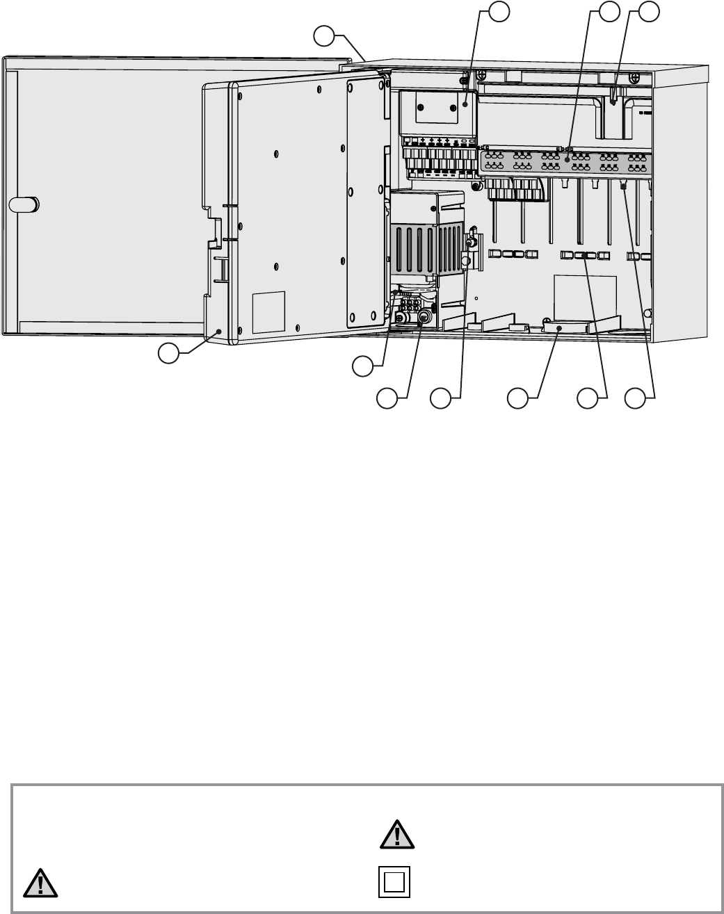
1. LCD Display – Backlit, adjustable contrast display
(re-lights when any button is pressed)
2. + Button – Increases flashing value, depending on
function
3. – Button – Decreases flashing value. Most items in
ACC screens “wrap” so that you can continue in either
direction through all the choices
4. Copy/Learn Button – Copies a time or value in a
flashing field, for pasting into similar fields. Also used
to learn typical flow (when a flow sensor has been
installed)
5. Paste/Pause Button – Pastes a copied time or value
into a new field. Also used as Pause/Resume feature
during watering, shuts off devices for 30 minutes or
until resumed
6. Programs Button – Selects one of the automatic
Programs (A-F), starts Test program, allows Reset
(with Reset button)
7. Up and Down Arrow Buttons – Used to move up and
down through adjustable functions in various screens,
and to select higher or lower numbered items
8. Left and Right Buttons – Used to move left and right in
some screens
9. Information Button – Lights display, and provides
instant help and other information, depending on dial
position. Also used to access Extended Features, when
held down while turning to specific dial positions
10. Programming Dial – Used to access all functions of
ACC. The most basic automatic watering can be set up
in the first 4 dial positions
11. Reset Button – Recessed switch erases some or
all memory when combined with pressing specific
buttons
12. Facepack Release Button – Hold down while removing
facepack from inner door panel
13. Door Grip – Convenient finger grip for opening inner
door
14. Logo Badge – Removable for installation of optional
communications modules
aCC InTerfaCe and Key ComponenTs .......................................
1
2 3 4 5 6
7
8
12
13
10
11
9
14
3
WIrInG ComparTmenT InTerIor ................................................
1. Inner Door – Opens to main wiring compartment
2. AC Wiring compartment – For connection of 120/230V
AC power with 1 x 0.75" (19 mm) conduit opening
3. Fuse – 2 Amp (fast) 250V, 6 x 20 mm
4. Conduit Openings, Low Voltage – 2" x 2½" (64 mm),
2" x ¾" (19 mm)
5. Wire Tie Holders for Valve Wires – Valve wiring area
6. Station Output Terminals (Valve Wires) – screw
terminals on 6-station output modules
7. Upper Deck Panel with Led Status Indicators –
Numbered station lights, green for active, red for faults
8. Sliding Lock for Output Modules – Permits addition
or removal of output modules, locks wired modules
in place
9. Master Module – Includes sensor, Pump/Master
Valve, and other accessory connections
10. SmartPort
®
– Integrated connector for ICR/SRR
receiver (on side of cabinet)
11. Earth Ground Lug – For connection of earth ground
copper wire (for surge protection only). Do not
connect valve commons – see Master Module for
Common wiring of solenoids and valves.
1
2
3 4 5 6
7 89
10
11
~
Explanation of Symbols
AC
Consult Documentation Double Insulated
Hazardous Voltage Present

4
meTal CabIneT, Wall mounT InsTallaTIon ...............................
Tools required:
• Long drill bit and extension
• Philips screwdriver or bit (for use with long
extension) – magnetic recommended
• Wire strippers
31"
(80
cm
)
F
acepac
k D
oo
r
Location Requirement: A) a switch or circuit-breaker
shall be included in building installations; B) the switch
or breaker shall be in close proximity to the controller,
and within easy reach of the operator; C) the switch or
breaker shall be marked as the disconnecting device for
the controller.
Avoid direct exposure to sprinkler spray.
Do not install controller within 20" (7 m) of
high-voltage electrical sources, such as service
transformers, pump station motors, etc.
Shaded or partially shaded areas are preferable to
prolonged direct sunlight.
The ACC controller is relatively heavy, about 30 lbs/13.6 kg
in the metal wall mount configuration. Mounting includes
a positioning hanger to assist with installation.
Mounting hardware has been included, but it is the
installer’s responsibility to insure that adequate hardware
is used for the physical location.
ACC is approximately 15½" (40 cm) wide. Allow another
15½" (40 cm) to the left of the controller for the door to
open freely.
Before mounting, it is easier to remove the metal cabinet
door. Swing the door open, grasp the top securely, and
push up on the bottom of the door, near the lower hinge.
The hinges should disengage and the metal door can be
removed.
Positioning Hanger
Mounting Holes
Remove the facepack assembly from the controller.
1. Open the facepack door using the recess on the
right.
2. Disconnect the gray ribbon cable from the back of
the facepack. Pull gently on the ribbon cable; a slight
rocking motion may help disengage the connector.
3. Push up on the upper door hinge, and tilt the door
so that it disengages the hinge posts. Remove the
facepack and set aside in a safe location.
4. OPTIONAL: Locate the positioning hanger in the
upper center of the controller’s location on the wall,
leaving adequate clearance for the opened door to
the left.
5. Drill a pilot hole for the anchor and insert.
6. Install one #10 (5 mm) screw in this hanger position,
leaving approximately ¼" (6 mm) out of the anchor
to allow the controller to hang from this screw.
7. Hang the controller from the keyhole slot in the
positioning hanger.
8. Place a level on the top of the controller cabinet and
level.
9. Locate the 3 mounting holes in the cabinet. These
are visible from the front, with the facepack
removed, in deep recesses in the top two corners,
and another shallow recess in the bottom center.
10. Mark each of these 3 locations and install anchors.
11. Reposition controller on the hanger and use a long
screwdriver or drill extension (3"/75 mm) with
magnetic tip to install the remaining 3 screws, one
at each anchor position, and secure.

5
The ACC can operate with either 120 VAC or 230 VAC power,
depending on how the incoming AC wires are connected.
Supply wires must be 14 AWG (2 mm) or larger.
The ACC is prewired for 120V operation but can easily be
changed to 230V.
Consult or hire a licensed electrician for these connections
as required.
• Turn AC power off at the source, and verify that it is
off.
• Remove the wiring compartment screws and the
wiring compartment door.
• Strip approximately ½" (13 mm) of insulation from the
end of each of the AC power wires, and route into the
wiring compartment through the conduit.
• Locate the white plastic terminal block, and wire
according to the following diagrams.
For 120V~ operation, connect the incoming black power
wire (hot) to align in the wiring block with the black wire
lead from the transformer.
Insert the incoming black wire lead into the hole opposite
the black transformer wire and tighten screw securely.
Connect the incoming neutral (white) wire to align with the
blue lead from the transformer.
Cap off the brown (230 VAC) wire if applying 120V and not
using a wiring block. The brown wire will be hot and have a
230V charge.
ACC Transformer
Black (120 VAC) U.S.White (Neutral) U.S.
or Blue (Neutral) Int'l
Brown (230 VAC)Blue (Neutral)
Black (120 VAC)
The green, or green-and-yellow safety ground
may not be required or permitted with this
floating ground, double-insulated transformer.
If desired and permitted, connect it to the earth
ground lug on the controller. Install a conduit
junction T-box below the supplied junction box
in the controller, and route the safety ground
out of the T to the earth ground lug of the
controller.
Tighten screw and replace cover.
For 230V~ operation, connect the incoming power
wire (hot, brown in many wiring standards) to align
in the wiring block with the brown wire lead from the
transformer. Connect the incoming Neutral (blue in some
international standards) wire to align with the blue lead
from the transformer. Tighten screws and replace cover.
Apply AC~ power and test. Refer to Earth Ground and
Station Wiring sections for additional connections.
ACC Transformer
Blue (Neutral)
Brown (230 VAC)Blue (Neutral)
Black (120 VAC)
Brown (230 VAC)
ConneCTInG aC maIn poWer, Wall mounT CabIneT .................

6
Location Requirement: A) a switch or circuit-breaker
shall be included in building installations; B) the switch
or breaker shall be in close proximity to the controller,
and within easy reach of the operator; C) the switch or
breaker shall be marked as the disconnecting device for
the controller.
2" Conduit Nut
2" Conduit Nipple
Mounting Plate
½" Conduit Nut
½" Conduit Nut
¾" Washer (4)
³∕8" Mounting Nut (8)
³∕8" Mounting Bolt (8)
Installing the Pedestal
1. Assemble the mounting template using the
instructions provided with the pedestal.
2. Using the enclosed mounting template, locate the
bolts two inches deep in the concrete pad, in the
locations indicated. The pad can be any size but at
least a two-foot square is recommended.
meTal CabIneT opTIonal pedesTal InsTallaTIon .....................
Select a location for installation of the controller based
upon these factors:
1. Availability of 120/230 VAC~ power.
2. Do not locate under overhanging branches of trees
or any structure that may attract lightning.
3. Avoid locations where sprinklers spray upward onto
the controller, and low areas subject to flooding.
4. Locate controller in a location that is central to all
valves/sprinklers that it controls to maintain visible
operation and reduce wire
lengths/costs.
3. Level the mounting bolts before the concrete sets.
4. After the concrete sets, remove the door of the
pedestal and slide the pedestal down onto the four
bolts. Secure the pedestal to the bolts using the
enclosed washers and nuts.
5. Remove the door and faceplate of the ACC and
attach the metal cabinet of the ACC to the top of the
pedestal using the ½" (13 mm) and 2" (50 mm) metal
conduit nuts in the pedestal. Tighten securely by
engaging teeth with a screwdriver and tapping in a
clockwise direction.
CONNECTING THE METAL PEDESTAL MAIN AC POWER
1. Connect AC power wiring as in the metal wall
cabinet. Route the AC power wiring through
the metal pedestal and up into the ACC wiring
compartment. Follow the AC wiring instructions for
the metal wall cabinet closely.
2. Replace the pedestal door first and then replace the
faceplate and the cabinet door. The pedestal door
cannot be removed or replaced when the cabinet
door is closed.
Refer to Earth Ground and Station Wiring sections for
additional connections.
Conduit Nuts
plasTIC pedesTal InsTallaTIon .................................................
AC Power Wire S/P
(3" Max Above Concrete)
GCBL Wiring (Required for IMMS)
(3" Max Above Concrete)
Field Wiring
(3" Max Above Concrete)
Thread Length 2.50" Min
Above Concrete
Template
5.00"
12.50"
26" Min
21" Min
4"
7
1. Set forms for a 21" (533 mm) wide x 26" (660 mm)
long concrete base. The base pad should be 2" (50
mm) above grade for proper drainage.
2. Position a 1½" to 3" (38 to 76 mm) diameter conduit
sweep elbow for the field wires (size will vary
depending upon the number of valve wires entering
the controller), a 1" (25 mm) conduit sweep elbow
for the power supply, and a 1" (25 mm) conduit
sweep elbow for any communication wires, if
applicable. Secure the sweeps so they will enter the
bottom of the controller correctly.
3. Allow approximately 3" (76 mm) of conduit above the
surface of the concrete pad.
4. Shape the concrete base to shed any water away
from the controller.
5. Prepare the template for insertion in the concrete.
Twist one nut on each of the four J-bolts to the
ConCreTe base InsTallaTIon ....................................................
bottom of the thread and slide each bolt through the
hole in the template. Put a washer and nut on each
J-bolt to secure it to the template (allow a minimum
of 2½" (63 mm) of thread protruding above each
nut).
6. Work the J-bolts down into the concrete until the
template sits level on top of the concrete. Smooth
and allow the concrete to cure (at least 24 hours).
NOTE: It is important with plastic pedestals to
ensure a smooth mounting surface. Uneven
surfaces may cause the pedestal to distort,
preventing proper sealing of the doors.
7. Remove the nuts and washers from the concrete
base. Place the pedestal over the bolts and secure
with nuts and washers.
NOTE: Remove both doors and lift the pedestal from the
main body. Two people are required for this task.
8
The ACC Pedestal controller can operate with either 120
VAC or 230 VAC power.
Supply wires must be 14AWG (2 mm) or larger.
The controller power must be connected to a branch circuit
protected by a 15 A rated over-current protective device
(circuit breaker, fuse, etc).
With the main AC power OFF, route the AC power wires from
the supply panel through the sweep elbow placed for this
purpose in the concrete pad.
Do not route low voltage wiring with the AC power wires in
the same conduit.
Locate the junction box below the transformer assembly on
the left side of the controller. The AC power connections are
made to the terminal block inside this junction box.
Route the AC power lines through conduit (if applicable)
into the junction box.
All connections are to be made by qualified electrical
personnel, only. Local electrical codes must be followed
and may vary, depending upon country, state, and local
codes.
ConneCTInG plasTIC pedesTal aC maIn poWer ........................
120 VAC CONNECTION
Place the Voltage Selector Switch in the “115V” position.
Connect the incoming black (or “hot”) wire to the Red wire
from the controller transformer. The Red wire is labeled
Hot, Phase, and Active. Connect either with the supplied
terminal block, or with approved high voltage electrical
wire nuts. If using wire nuts, tape the connection securely
with electrical tape.
Connect the incoming white wire (neutral) to the blue wire
from the controller transformer (labeled “Neutral”), either
with the terminal block or approved wire nuts. If using
wire nuts, tape securely.
The green or bare copper safety ground is not required
with this UL listed floating ground, double-insulated
transformer. If desired, you may connect it to the earth
ground lug on the controller. Install a conduit junction
T-box below the supplied junction box in the controller,
and route the safety ground out of the T to the earth
ground lug of the controller.
230 VAC CONNECTION
Place the Voltage Selector Switch in the “230V” position.
Connect the incoming Brown power wire to the Red wire
from the controller transformer, with the supplied terminal
block. The Red wire is labeled Hot, Phase, and Active.
Connect the incoming Blue power wire to the Blue wire
from the controller transformer at the terminal block. The
Blue wire is labeled Neutral.
The green, or green-and-yellow safety ground may not be
required or permitted with this floating ground, double-
insulated transformer. If desired and permitted, connect it
to the earth ground lug on the controller. Install a conduit
junction T-box below the supplied junction box in the
controller, and route the safety ground out of the T to the
earth ground lug of the controller.
Place the connections up into the junction box through the
opening in the bottom. Secure conduit if applicable.
Turn breaker power on, then turn the controller power
switch on and test.
The controller is equipped with a 6 x 20 mm, 250V, 2 Amp
fast-blow fuse on the transformer assembly. Incorrect
power wiring may cause this fuse to open. Check wiring and
incoming power if the fuse opens when power is turned on.

9
Junction
Box
Terminal Block:
Red Wire =
"Hot" or Active
120V Black
230V Brown
White (US)
Blue (International)
Terminal Block:
Blue Wire =
Neutral
Controller Power
Switch
Voltage Selector
Switch

10
ConneCTInG earTh Ground (all ConfIGuraTIons) ...................
The ACC features a copper earth ground lug, to the
immediate right of the transformer assembly.
This earth ground connection is isolated from the primary
AC power and is used to ground incoming surges from the
communications and output valve wires.
With the controller power Off, loosen the slotted screw in
the center of the ground lug.
Route a bare 6 AWG (4.11 mm) earth ground wire into the
wiring area through the 0.75" (19 mm) conduit opening
directly beneath the ground lug, in the bottom of the
controller cabinet. Do not route the ground wire through
the same conduit as the incoming primary AC power!
Loosen the ground lug screw, insert the ground wire into
the ground lug and tighten the screw to secure the ground
wire. Do not overtighten.
Grounding hardware should be selected according to
standards established by American Society of Irrigation
Consultants Earth Grounding guideline 100-2002
(available at their website, www.asic.org).
Acceptable grounding consists of an 8' (2.5 m)
copper-clad rod or stake, or a 4" x 96" (100 mm x 240 cm)
copper plate, or both, placed in the earth at least 8' (2.5
m) away from the controller, and with the ground wire at
right angles to the communications and valve wires, if
possible. Ideal grounding resistance would be 10 Ohms
or less as measured with a “megger” or similar device.
Please consult the ASIC reference for more detailed
considerations of this critical step.
Improper connection to earth ground voids the
effectiveness of the output module surge protection.
Ground Lug
Ground Wire in
½" (13 mm) conduit

11
InsTallInG sTaTIon modules.....................................................
ACC expands in 6-station increments with intelligent output modules, requiring no tools to install and only a screwdriver
for station wiring connections. The base configuration is 12 stations (two 6-station modules installed) with a maximum
station capacity in a metal wall cabinet of 42 stations (7 total output modules x 6 stations each).
ACC can be expanded at any time with either of the following types of modules:
1. ACM600, 6-station output module with surge suppression and diagnostic LEDs
2. AGM600, 6-station output module with heavy-duty surge suppression and diagnostic LEDs
These two types of modules may be mixed within the same installation if desired.
1. To install expansion modules, turn the dial to the
“Run” position.
2. Open the inner facepack door, and locate the module
lock. Slide the module lock to the “Power Off”
position.
3. Flip up the upper deck cover. Slide the modules up,
into the next available position, viewed from left to
right. Do not skip slots by leaving them empty.
4. Install a module by aligning it firmly in the lower
portion of the next available slot and sliding straight
up until it clicks into place. Once module is in place,
slide power bar to the "Power On" position. The
first two lights of the bottom and top row of each
module installed will light up red for 1 second,
indicating proper contact and the new module has
been recognized. The red lights will then turn off, in
sequence, from left to right across the modules that
are installed.
5. The silver contact on the back of the controller
cabinet must engage a mating slot in the back of the
expansion module. Do not “tip” or force the module
into place. Slide straight up, from the bottom of
the slot.
6. While at the Run dial position, press the Information
button. The current station size will be shown, and
should include any new modules you have added.
US PATIENT NO 6,842,667 B2
ET FLOW SEN4 SEN3 SEN2 SEN1
ET FLOW SEN4 SEN3 SEN2 SEN1 COM
P/M1 P/M2
24
VAC
1 2 3
4 5 6
7 8 9
10 11 12
13 14 15
16 17 18
19 20 21
22 23 24
25 26 27
28 29 30
31 32 33
34 35 36
3837 39
40 41 42
OUTPUT MODULES (ACM600, AGM600)
A. Station Output Screw Terminals – Connect no more
than two solenoids each.
B. Station Status LEDs – Green for station activity, Red
for fault or short
C. Locking lugs – For module lock
D. Gold plated electrical contacts – Lower rear of
module
E. Additional surge components, AGM versions –
Visible through module
Slide ADM99 in
first 3 slots
Upper Deck cover
ADM99 Decoder
Output Module
A
B
C
D
E
ACM600
6-station output
module
AGM600
6-station output module with
heavy duty surge protection
Station Modules
Decoder Output Module

12
CONNECTING THE VALVE WIRES
Each station output module has 6 screw terminals for
connection of individual station wires. The terminals will
accept from 22 AWG (0.64 mm) to 12 AWG (2.05 mm) wires.
Each station output is rated for 0.56 A, max or enough to
operate two typical Hunter solenoids simultaneously.
Once the output module is installed in the slot, the station
numbers assigned to the output module appear in the
upper deck label above each slot.
1. The modules may be removed, if necessary, without
disconnecting the field wiring. However, they must
be reinserted into exactly the same slot, or the
station addresses will be switched.
2. Connect the return wires from the valves to one of
the 3 terminals on the Master Module marked COM.
Since many valve solenoid wires will need to connect
to these 3 common terminals,
3. Route valve wires between control valve location and
controller.
4. At valves, attach a common wire to either solenoid
wire of all valves. This is most commonly a white
colored wire. Attach a separate control wire to
the remaining wire of each valve. All wire splice
connections should be done using waterproof
connectors.
5. Open hinged faceplate on the controller to access the
terminal area.
6. Route valve wires through the conduit and attach
conduit to the controller at the large conduit
openings on the right side of the bottom of the
cabinet.
7. Strip ½" (13 mm) of insulation from ends of all wires.
Secure valve common wire to COM (Common)
terminals on the Master Module. Then attach all
individual valve control wires to appropriate station
terminals.
DECODER OUTPUT MODULE (ADM99)
A. Two Wire Path Terminals – Connect no more than
one pair of red and blue wire paths to each output
terminals
B. Status LEDs– Decoder Fault, Module/Line Activity,
Communicating, Line Status
C. Locking Lugs
D. Gold-plated Electrical Contacts
E. Programming Port – Port where decoder wires get
plugged into in order to program the decoder
Slide ADM99 in
first 3 slots
Upper Deck cover
ADM99 Decoder
Output Module
A
B
C
D
E
ACM600
6-station output
module
AGM600
6-station output module with
heavy duty surge protection
Station Modules
Decoder Output Module
1. Decoder output modules may NOT be mixed with the
“conventional” ACM/AGM-600 output modules.
2. Decoder output modules are always installed in the
first three slots.
3. Install the ADM99 by aligning it firmly into the first
three station module slots, and sliding straight up
until clicks into place. As soon as the ADM99 is slide
into place, the Module/Line Activity light will light
red for one second, and then the Line Activity light
will illuminate green. Unlike the station modules,
the ADM99 will illuminate the status lights with the
power bar in the "Power Off" position.
CONNECTING DECODER OUTPUT PATH WIRES
Up to 99 stations may be operated over a single pair of
wires (known as a “path”) using decoders. The decoder
output module allows up to 6 two-wire paths to the field
decoders. The maximum number of decoder stations is
still 99, but multiple paths allow the shortest wire runs.
You may use any number of paths to reach all 99 stations.

13
Each path should consist of Hunter Industries Model
IDWIRE1 or IDWIRE2 color-coded decoder wire. This is
a twisted, solid-core wire suitable for direct burial, and is
always color-coded red and blue.
All red/blue connections in the two-wire path must be
made with DBR6 waterproof connectors or equal.
Each path has a red and a blue terminal with its number on
the decoder output module.
1. Route decoder path wires through the conduit into
the wiring compartment. Leave adequate slack in the
wires for thermal contraction.
2. Strip ½" (13 mm) of insulation from the red and blue
ends.
3. Connect the red wire to the red “1” terminal, and the
blue wire from the same pair to the blue “1”. Repeat
for any other paths as needed.
Do not connect the paths in a loop, or back to any other
point in the controller. Leave the red and blue paths
separate at the end of each two-wire run. Simply insert
decoders in the path until complete, and stop at the
last decoder on the path. If this is not possible, simply
cap each of the ends of the two wire path with a DBR6
waterproof connectors or equal.
Do not connect a wire path from one controller to another
controller!
When a decoder output module is installed, the controller
facepack will recognize it and the station size will change
to “99” (regardless of how many stations are in use). This
will also unlock the normally Extended Decoder displays in
the following dial positions. See DECODER OPERATIONS
(ACC99D VERSIONS) on page 56 for more information.
Key ConneCTIons .......................................................................
1. Common Ground Terminals (x 3) – For return wires
(often white) from stations and master valves. Field
wiring may be returned to any of these 3 terminals
2. P/M1 – Pump/Master Valve output 1, and status light
(return Pump/Master valve circuit to any of the 3 Com
common terminals). Output is 0.320 Amps max
3. P/M2 – Pump/Master Valve output 2, and status light
(return Pump/Master valve circuit to any of the 3 Com
common terminals). Output is 0.320 Amps max
4. Hardwire terminal connection cover – Remove
to install optional ACC-HWIM for hardwired
communications.
5. 24VAC – Always-on 24V test terminal, for locating
valves in the field. Can also be used to power low-draw
sensor receivers such as Hunter WRC. Output is 0.420
amps maximum
6. Flow Sensor connections (+ and -) – Connections for
Hunter HFS flow sensor
7. ET connections (+ and -) – Not used. Connections for
Hunter ET Sensor only. If upper ET terminal is colored
red, Master Module requires update for use with ET.
8. If Master Module has a sticker that says “ET Ready,” or
if the version number of the module is 4.0 or later, the
Master Module is ET ready
9. Sensor Connections (1-4) – Connections for up to 4
Clik-family sensors, or other normally closed switch
contacts
1
3
2
4
5
67
8

14
ConneCTInG The masTer ValVe(s) and/or pump sTarT relay(s)
The Pump/Master valve connections are located in the
upper right of the Master Module, which is in the upper left
corner of the controller itself.
Locate the P/M1 and P/M2 screw terminals on the Master
Module. These outputs are designed to supply 24 VAC,
0.320 A max, for a single Master Valve solenoid or a Pump
Start Relay (or Relay Booster).
The return wire from each P/M device (solenoid or relay)
must be connected to one of the COM terminals on the
lower terminal strip of the Master Module.
Connect one output wire from each Pump relay or Master
Valve solenoid to the desired 24 VAC P/M terminal.
Connect the return wire to one of the terminals marked
COM immediately below the P/M outputs.
Configuration of the P/M terminals is covered in the
Set Pump Operation section of the Programming and
Operations portion of this manual.
Up to 4 Hunter sensors can be connected to the ACC
controller, including:
• Mini-Clik
®
• Rain-Clik
™
(including Wireless Rain Clik)
• Freeze-Clik
®
• Mini-weather station
Hunter Flow-Clik
™
can also be connected, but it is
recommended that the HFS be used instead.
In the ACC controller, Clik sensors shut down individual
programs, not necessarily the entire controller. Each
sensor can be given its own response instructions by
program.
Hunter Clik sensors are usually normally closed, and open
on alarm. This signals the controller to suspend irrigation.
Other dry contact closure sensors can be used without
warranty, provided that a.) they require no voltage; and
b.) open the circuit when a shutdown condition is sensed.
Hunter makes no claims or representations that such
connections will be effective.
1. To connect Clik sensors, locate the SEN [1-4]
terminals on the Master Module (upper right corner
of controller).
2. Route the pair of wires from each sensor into the
cabinet through one of the low voltage conduit
openings in the bottom of the enclosure.
24 VaC TesT TermInal ................................................................
The Master Module features a “constant-hot” 24 VAC
output which can be used as a test point for locating
valves in the field:
1. After powering up the controller, attach the common
wire to the COM terminals as described above.
2. Touch each wire to the terminal marked 24 VAC to
identify the valve location.
3. Each valve will open electrically when the wire is
touched to the 24 VAC terminal.
4. After identifying the valve location, you may then
insert the wire into the appropriate terminal. This
feature allows you to sequence the valves in the
most logical order for the user without damaging the
controller by “sparking” the wires.
5. The 24 VAC terminal may also be used to power
wireless Clik sensor receivers. See Connecting a
Rain Or Freeze Shut Off Device on page 14 for more
information..
ConneCTInG a raIn or freeze shuT off deVICe .......................

15
3. The sensor connections are made in dedicated pairs:
one wire to the sensor number + terminal, the other
wire from the sensor to its – terminal. Do not twist
common wires together from different sensors and
connect them to the same terminal.
4. Loosen the screw for the first sensor terminal
(SEN1), and connect either of its wires to the +
terminal and tighten.
5. Connect the other wire from that sensor to the SEN1
– terminal and tighten.
6. To connect the wireless Rain Clik (WRC) or wireless
Rain-Freeze Clik receiver, consult the instructions
supplied with the WRC for mounting and addressing.
7. Connect either of the receiver’s Yellow power wires
to the “24 VAC” terminal on the Master Module (the
“24 VAC” terminal has a 400 mA maximum capacity
and is adequate for Clik receivers).
8. Connect the other Yellow receiver wire to any of the
COM terminals.
9. Complete the wireless Clik installation according to
the WRC instructions.
All additional programming is performed at the facepack
and is described in the Set Sensor Operation section of
Programming and Operations.
ConneCTInG The hunTer floW sensor .....................................
The HFS is the primary flow meter for which ACC flow
functions have been designed. Additional types of flow
sensor connections may also be possible. Consult flow
sensor manual for wiring and calibration information.
1. To connect a HFS, route the pair of 18 AWG (1 mm)
wires from the sensor into the cabinet through one
of the low voltage conduit openings in the bottom of
the enclosure.
2. Locate the “Flow” red and black coded terminals
near the left side of the Master Module. Connect the
red wire from the HFS to the red terminal, and the
black wire from the HFS to the black terminal.
3. Reversing the red and black connections will
probably not damage the units, but will not allow the
ACC to read flow.
4. Flow setup, learning, and configuration is described
in the Set Flow Monitoring section of Programming
and Operations.

16
Some other brands or models of flow sensors may be
compatible with the ACC controller. One known-compati-
ble model is Data Industrial model IR-220B (also sold as
Hunter model GENDATFL).
NOTE: The ACC flow sensor connection is a 20 VDC pulsed
output which senses interruptions as “clicks”. It is DC
voltage, and the polarity must be observed.
The red + terminal corresponds to the red wire on the HFS
sensor, and if connecting to other brands of sensor insure
that correct polarity is observed.
Connect the positive (+) wire to the red Flow terminal on
the Master Module, and the negative (–) wire to the black
terminal.
ConneCTInG oTher floW sensors ............................................
The ACC controller has an integrated SmartPort
®
‚ on
the cabinet’s upper left side, or inside the front panel of
the plastic pedestal. This connection is automatically
compatible with Hunter ICR and SRR remote receivers.
To connect: remove the weather-resistant rubber cover
(metal cabinet versions), align the remote receiver’s
pins with the mating receptacle, and push firmly until
the receiver is fully seated. If the ET System adapter is
installed, plug the receiver into the mating connector on the
adapter.
If the receiver address is to be changed, hold in the green
button while plugging the receiver into the SmartPort, in
accordance with the ICR instructions.
Refer to the remote control’s instructions for additional
addressing and operations. However, there are some
significant differences in operating the remotes with the
ACC controller, from previous Hunter controllers.
When a program or station is started by ICR, the ACC
display will (as always) show why the program or station is
running. Remote starts are followed by “ICR” in the display
(Fig.1).
To set up an ICR remote control for operations with ACC,
consult the ICR instructions. Use the Mode button on the
ICR transmitter to select a station size of “240” to allow
access to all ACC programs and stations. Only ICR Remotes
manufactured September 2006 or later are compatible with
ACC. If you have an older ICR remote, the maximum station
size is 48. Therefore, if you are using an older remote and
an ACC decoder controller, the highest station you will be
able to control is station 48. You must obtain a newer ICR
to operate correctly with any ACC controller.
MULTIPLE STATIONS SIMULTANEOUSLY
ACC is an overlapping controller, and will allow up to
6 stations to run simultaneously. While other Hunter
controllers will stop existing stations when a new ICR
remote start command is received, the ACC will continue to
run existing stations along with the new stations, until the
maximum of 6 events has been reached (Fig. 2). If 6 events
are running and an ICR command is received to start another,
the command will be ignored. No new remote commands will
be accepted until one of the 6 events times out.
ICr remoTe ConTrol .................................................................
Figure 1
Figure 2

17
ACC can therefore run automatic programs, manual
station and programs, and ICR commands simultaneously.
Each running event will be shown on the display with
the reason for running (programs will be shown with the
program letter followed by “ICR” if they were started by
the remote), and the remaining time for the event.
The display shown here is possible with ACC: six events
are running, including ICR station starts (ICR), ICR
program starts (A-ICR), manual single-stations (MAN),
manual program starts (C-MAN), and an automatic
program (D-AUTO).
Figure 3
If simultaneous operation is not desired, press the
Off button on ICR before starting another program or
station. Off will stop everything the controller is running,
regardless of what started it.
Stacking and SmartStack rules are not observed when
manual single station ICR commands are sent to the ACC.
Stacking and SmartStack rules do apply when manual
program ICR commands are sent to the ACC. If a program
is not set to overlap, the ICR command will be ignored
when trying to start the manual program.
ICR manual single station commands will be obeyed
if the controller is in the OFF position, or in a sensor
shutdown mode. ICR manual program commands will
NOT be obeyed and will be ignored in the OFF position. If
the controller is in a sensor shutdown mode and an ICR
command is sent to activate a program, the ACC will obey
the sensor shutdown if that program is assigned to pause
or suspend according to the sensor. The manual program
ICR command will be shown in the display as in pause or
suspend mode, depending on how you have your sensor
programmed. (Fig 3) If the program that you are trying to
manually start with an ICR command is not programmed
to pause or suspend a sensor, the command will be obeyed
and the program will run.
If you are utilizing a simultaneous station group, or SSG,
you may run an individual station that is included in the
SSG. The fact that the station is included in the SSG will be
ignored, and you may run that station by itself.
ConneCTInG To Imms .................................................................
hunTer IrrIGaTIon manaGemenT and monITorInG sysTem
ACC controllers can upgraded to provide full two-way
communications with central control software (IMMS 2.0).
The ACC Com modules are installed in place of the logo
badge on wall mount controllers, and under the facepack
door in a special bracket (APPBRKT) in pedestal units.
ACC controllers can be connected with hardwired cable
(GCBL), dial-up telephone (POTS or “plain old telephone
service”), or GSM cellular communications (using Circuit
Switched Data or CSD).
Multiple controllers can share a connection, with
additional runs of hardwired cable or UHF radio
communications. Advance to Daylight Saving and use +/-
to select YES.
No tee splices are permitted within the GCBL and all
hardwired devices must be in one single continuous wire
run.
DIAL-UP TELEPHONE (ACC-COM-POTS)
Connection must be within 6 ft (2 m) of the telephone
company connection, via standard RJ-11 jack..
IMMS 2.0 and dial-up Com modules require analog lines
with dial tone. These products do not have digital dialing
capabilities.
Dial-up must be via dedicated line. The controller will
always answer on the first ring and must not share with
fax machines or other devices.

18
For experienced operators, the fastest steps to initial
programming are as follows.
1. Set Current Date/Time: Use the arrow buttons to
navigate, and the +/- buttons to change. Set the Date
and Time and choose Units of Measure.
2. Set Watering Start Time: Each automatic Program
has 10 start times. At this position, use the
Programs button to select individual programs,
and the 10 possible start times for that program will
appear. Use arrows to navigate and +/- to change
See SETTING PROGRAM OVERLAP OPTIONS on
page 36 for more information..
3. Set Station Run Times: At this dial position, use
the Programs button to select the program you are
setting up. Then, use the +/- buttons to change the
hours:minutes:seconds run time for each station.
Use the up and down arrows to move to the next
station. TIP: Use the Copy and Paste buttons to move
quickly through large numbers of similar stations.
Set the first station’s run time, then press Copy. Use
the Up arrow to move to the next station, and press
Paste.
4. Set Days to Water: Use the Programs button to
select the Program. Use the arrows to move to Day
Sched, and choose Schedule Type (Day of Week,
Interval, or Odd/Even).
5. Set Pump Operation (optional): The two Pump/
Master Valve outputs may be set by station at this
position. If no pump or Master Valve is in use, this is
not required.
CELLULAR/GSM (ACC-COM-GSM, GSM-E)
GSM cellular service must have reliable coverage at
installed site.
GSM service must permit and provide Circuit Switched
Data (CSD). IMMS 2.0 connections require CSD and will
use the Data telephone number. No other form of cellular
communications will work. There are no CDMA options for
ACC communications at this time.
UHF RADIO
All UHF radio communications require a license.
All radio communications for ACC work with RAD3 radio
module or later. IMMSR radios, designed for original
IMMS Site Interfaces and Controller Interfaces, will NOT
work with ACC controllers.
poWer faIlures ........................................................................
The ACC’s real time clock is independent of external power
or the 9 VDC battery, and will keep time during a power
failure of virtually any length. When external power is
restored, the ACC will still have the correct time and will
be ready to irrigate.
QuICK sTarT ................................................................................
A Power Outage message will be stored in the Alarm Log,
with time of the outage. Another log is stored when power
is restored.
RAD3 radios are not supplied with antennas, but an
antenna must be provided for the radio to operate, and the
antenna must be installed outside of any metal enclosure
(including the ACC metal cabinet).
Radio communications for the ACC are only to
communicate with other ACCs, and do not provide
communications directly with a central computer. This
should be established with an IMMS-CCC and a hardwire
interface, or by telephone using ACC-COM-POTS or
ACC-COM-GSM (or GSM-E for international applications).
For golf applications using Surveyopr central control
software only, the AGCHUBR provides a direct radio
interface to all radio-equipped ACC/AGC controllers.
See Hunter’s ACC System Design Guide for important
details regarding design of central control systems.
19
6. Return the dial to the Run position. This is all that
is required for the most basic operations. ACC will
water automatically in any dial position except
“OFF”.
7. Test: The Test program will start every station in the
controller sequentially, in numerical order, for the
specified time. The minimum time is one second
for conventional controllers, and 15 seconds for
decoder controllers. The maximum run time in Test
Program is 15 minutes per station. Turn the dial to
the Run position. Test is started by holding down the
Programs button for 3 seconds. Enter the Test time
and wait 5 seconds for the Test cycle to begin. Each
station LED on the output modules will light green
when a station is running, red if a fault is detected.
Decoder controllers cannot show individual station
activity , but the ADM99 lights will show activity on
the Communicating and Module/Line Activity lights
during operations.
Decoder controllers will start all 99 stations in the
test mode. It does not matter how many decoders
are installed in the field, the controller will try to run
all 99 stations. The controller will receive alarms
for any stations that are not present in the field, or
stations that are not assigned to a decoder. When
running the Test Program in a decoder controller,
you can manually end the Test by turning the dial to
Off after the last “real” station has run.
Test actually starts stations, and this will cause
actual watering in a fully installed system.
8. Manual Start: Turn the dial to the Manual Operation
dial position to manually start any Program, or
single station. When the display shows Manual
Program, use the Programs button to select the
Program, and turn the dial to the Run position. The
program will start in a few seconds. TIP: You can
also hold down the right arrow button for 3 seconds
to shortcut to Manual starts.
9. To start a Single Station: When “Program” is
flashing, use the + button to change to Manual “One
Station”. Use the down arrow to move to the station
number, and +/- to select a station. Use the down
arrow to move to the run time, and +/- to change
the run time (hh:mm:ss format, from 1 second to 6
hours). Turn the dial back to the Run position, and
the station will start within a few seconds.
ConTroller proGrammInG and operaTIon .............................
USING THE INFORMATION BUTTON
The Information button is used to provide programming
tips, summary information and/or to unlock extended
features, depending on the dial position. If a flow meter
is installed, press the Information button (with dial in the
Run position) to see actual flow at any time.
If the backlit display turns off while you are programming
(it will time out after 5 minutes of inactivity), press the
Information button to relight it (to prevent accidental
changing of any settings by pressing the other keys).
Pressing and holding the Information button will change
the screen to either a summary screen of that dial position
or will provide a programming tip. Releasing the button
will return you to the normal programming screen for that
dial position.
Some dial positions have extended features that are
accessible by holding down the Information button, and
then turning the dial to that position.
This will unlock the extended features. Extended
features are features that are protected from accidental
re-programming because they are critical to the proper
operation of the controller. Programming these extended
features is explained in the Extended Features section. The
ACC has the following Extended Features:
• No Water Window
• Delay between Stations
• Making the M/V circuit Normally On (instead of
Normally Off) and M/V circuit location (Controller or
ADM for Decoder controllers)
• Setting the Flow Sensor size and type
• Set individual station parameters (Flow, Limit, and
Delay) and flow sensor location (Controller or ADM
for ICD-SEN sensor decoder)
• Set sensor location: set each sensor to controller,
ADM for for ICD-SEN location, or ET for individual ET
sensors
• SSG (Simultaneous Station Group) setup
• Custom Manual program setup
• Test Program
• Easy Retrieve™ backup

20
SETTING CURRENT DATE AND TIME
Three items are programmed at this position:
• Time of Day and Date, the day of the week sets
automatically
• Daylight Savings time usage
• Units of measure, English or Metric
Turn the dial to the SET CURRENT DATE/ TIME position
Press the + or – button to change the value of the flashing
cursor. Hold the button down to advance rapidly over a
large range of numbers.
Press the arrow buttons to change cursor position.
Set the hour and the minutes, then advance to the AM/
PM field. Use + or – to select AM, PM, or 24 hour clock
(international, or “military” time). If 24 hour clock is
selected, Program Start Times and other controller times
will also be displayed in 24 hour format.
Press the arrow buttons to advance and set the date in
MM/DD/YY format.
ACC Daylight Saving Time has been updated for the new
USA requirements. If set to Yes, time will offset one hour
forward at 2 AM on the second Sunday in March, and reset
("fall back") on the first Sunday in November.
Units of Measure: choose English or Metric. This will set
the unit type for the entire controller.
SETTING PROGRAM START TIMES
Three items are programmed at this position:
• Overlap or Stack start time priority
• Start times for each of the six programs (A – F)
• Extended Feature: No Water Window
To Set Program Start Times
1. Turn the dial to the SET PROGRAM START TIMES
position
2. Select the Program (A – F) by pressing the Program
button
3. Press the arrow buttons to change cursor position
4. Press the + or – button to change the value of the
flashing cursor
5. Select Stack or Overlap for the Program. It is
important to know that if the setting within the Set
Program Overlap Options dial position is not set
to "Stack or Overlap," the option of selecting Stack
or Overlap (at the Start Times position) will not be
possible.
6. The copy and paste buttons may be used to speed
up programming (press the Copy button at any Start
Time position, then move to another position and
press the Paste button. The same Start Time will be
pasted there).
Stacked Start Times
Stacking means that programs are not allowed to overlap;
if one Program is set to start before another Program has
completed, it will be pushed back (“stacked”) regardless
of its actual start time.
Each of the six programs (A – F) has ten start times
available, for a total of sixty available automatic starts. The
default is to stack the start times in alphanumeric order.
Program A will read Overlap, but all other programs will
read Stack. For instance, start time “Program A at 8:15
AM” would start before “Program B at 8:15 AM” because
A comes before B. The Start Time for Program B at 8:15
AM would start following the completion of Program A’s
watering.
Overlapping Start Times
Overlapping start times allows more irrigation to occur
simultaneously. Overlap starts Programs at their exact
Start Times, regardless of other Programs that may be
running (it is the opposite of Stacking). All six programs
can be programmed to Overlap and thus potentially run
simultaneously. This is great when a short watering
window is necessary and the hydraulics of the system
allows for high total water flow.

21
CAUTION: Understand your irrigation system’s hydraulic
restrictions before allowing programs to overlap.
Overlapping programs may overdrive the hydraulics of
your system. Overdriving your hydraulics will damage the
components and result in inferior sprinkler performance.
More advanced programming overlap options are available
by turning the dial to the SET PROGRAM OVERLAP
OPTIONS dial position.
Normally, the cursor will be positioned at the first Start
Time hour position when turning the dial to the Set
Program Start Time position.
• To change the Stack/Overlap settings for the Program,
use the arrow key to navigate up to the Stack/Overlap
indication.
• Use + or – to change between Stack and Overlap.
• Use the arrow keys to move back down to the Start
Times if necessary.
Multiple Start Times
To set Start Times for the Program, move to the Start Time
number, and use the + or – buttons to set the hour, then
minutes, and then AM/PM settings unless using 24-hour
option.
• If a Start Time is skipped (for example, a time is set
for 1, 2 is left at OFF, and a time is set for 3), the Start
Time will be accepted, but when returning to this
dial position, the Start Times will be moved to a
sequential order (the Start Time set for 3 will have
been moved to 2). This is by design.
• If an earlier Start Time is set for a higher-numbered
Start (for example, Start 1 is set to 4:00 AM, and
Start 2 is set to 3:00 AM), when returning to this dial
position the Start Times will have been reorganized
in chronological order. The lowest numbered Start
Time will always have the earliest time of day (in the
example, Start 1 will be at 3:00 AM and Start 2 will be
at 4:00 AM).
Press the Information button while in the Set Watering
Start Times position to show a summary of all Start Time
information for the selected Program. This will show total
station run time per start, number of starts, and total time
for the program.
No-Water Window
Programming this feature is explained in the Extended
Features section.
SETTING STATION RUN TIME DURATION
Three items are programmed at this position:
• Station watering duration
• Seasonal Adjust value for the Program
• Hidden Feature: Timed Delay between Stations
1. Turn the dial to the SET STATION RUN TIMES position.
2. Select the Program (A – F) by pressing the Program
button
3. Press the + or – button to change the value of the
flashing cursor. The cursor initially appears in the
minutes field.
4. Press the right and left arrow buttons to change
from minutes to hours or seconds cursor positions.
Set the run time in h:mm:ss format.
5. Run times may be from 1 second to 6 hours, or any
increment in between.
6. Press the up and down arrow buttons to change to a
different station number
7. The copy and paste buttons may be used to speed up
programming.

22
NOTE: If the ACTUAL value is different from the
PROGRAMMED value, Seasonal adjust has been changed
from the default of 100% to a new value. The actual run
time is the duration the station will water.
Press the Information button with any station selected at
the Set Station Run Times dial position to see a summary
of all watering for a specific station, including all
programs in which it will run.
CHANGING SEASONAL ADJUST
Season adjust is used to make global or program specific
run time changes without the need to reprogram every
station’s run time. Seasonal adjust made at the controller
level is global (GLBL) , and the controller can be adjusted
in 1% increments, from 1 to 300%. This will change run
times by the set percentage.
For example, a 10 minute run time that is adjusted to 70%
will run for 7 minutes. When the controlleris set back to
100%, the station will return to a 10 minute run time.
Programs that are set to GLBL will use the Global Seasonal
Adjust setting that has been set for the controller.
It is also possible to set Seasonal Adjust percentages for
individual programs (also 1–300%). The programs will
use their own percentages and will not be affected by the
controller-level Global Setting. The percentages are not
multiplied together. If the controller is set to 150%, but
an individual program is set to 70%, the stations in the
programs will run for 70% of the original run time, not
70% x 100%.
Turn the dial to the SET STATION RUN TIMES position.
Using the Global Setting
1. Press the left arrow button until the cursor is on
the percentage below the GLBL. The percentage
immediately below GLBL is the seasonal adjustment
percentage for the entire controller.
2. Press the + and – buttons to adjust the global
seasonal adjust value between 0 and 300%.
Using a Program Specific Setting (set Season Adjust by
Program)
1. Press the left arrow button until the cursor is on the
GLBL.
2. Press the + and – buttons to adjust the season adjust
value between 0 and 300%.
NOTE: If it is desired to return to the global season
adjust, move the cursor to the season adjust
percentage then use the + and – buttons to change
the value to GLBL. GLBL is located between the 101
and 100% positions.
Timed Delay between Stations
Programming this feature is explained in the Extended
Features section.
SETTING DAYS TO WATER
Each Program’s days to water are programmed at this
position.
Set Days to Water
1. Turn the dial to the SET DAYS TO WATER position
2. Select the Program (A – F) by pressing the Program
button
3. Press the + or – buttons to change from DAYS (day of
the week), INTERVAL (1 – 31 DAYS), or ODD or EVEN
days of the month.

23
Day of the Week Watering
1. Select the Program and DAYS .
2. Press the down arrow button to move the cursor to
Monday
3. Press the + button to water on Mondays or the –
button to not water on Mondays
4. As the cursor moves from day to day, press the +
or – button to water or not water on that day of the
week. Press the right and left arrow buttons to move
quickly to a specific day.
Interval Watering
1. Select the Program and INTERVAL with the + or –
buttons.
2. Press the down arrow button to Interval
3. Press the + or – button to select the number of days
between watering
4. Press the down arrow button to Next Water
5. Press the + or – button to select the number of
days until the next watering. If Next Water has
"0 days" for a value, that indicates that any scheduled
watering for that day will water at its programmed
start time. If it has a value of "1 Day," the scheduled
programming will water tomorrow.
Non-Water Days: This feature can be used to omit
watering on mowing days, etc. The days with N will not
water, even if they would normally occur at one of the
Interval days set above.
1. Press the down button to MON
2. Press the right and left arrow buttons to move the
cursor between the days
3. Press the – button when the cursor is on a day that
you do not want to water. An “N” will appear, to show
that day is never able to water, regardless of the
schedule.
4. If you select Odd or Even while in the Interval
schedule, the Odd or Even days will not be watered
even if they happen to be one of the Interval days to
water.
5. To change a non-water day back to a water day, use
the arrow buttons to go to that day and press the +
button. The “-“ will disappear, and the day will be
available for Interval watering again.
Odd/Even Watering
1. Select the Program and ODD/EVEN with the + or –
buttons, as shown above in First Step
2. Press the down arrow button once, to select Odd or
Even.
3. Press the + or – button to toggle between ODD or
EVEN day watering
Non-Water Days: This feature is frequently used to omit
watering on mowing days, etc.
1. Press the down button to MON
2. Press the right and left arrow buttons to move the
cursor between the days
3. Press the – button when the cursor is on a day that
you do not to water. An “N” will appear, to show
that day is never able to water, regardless of the
schedule.
4. To change a non-water day back to a water day, use
the arrow buttons to go to that day and press the +
button. The “-“ will disappear, and the day will be
available for Odd or Even watering again.
SETTING PUMP AND MASTER VALVE OPERATION
Two items are programmed at this position:
• Pump or Master Valve (P/MV) operation by station.
Each station may have any combination of P/MV
outputs 1, 2, both, or neither, which will activate as
specified whenever the station is turned on.

24
• Extended Feature: Change the master valve from the
default of normally closed (N.C.) to normally on (N.O.)
Change the location of the P/MV between Controller
(wired directly into the Master Module) and ADM
(P/MV is connected to a decoder on the two-wire path)
Set Pump and Master Valve Operation
1. Turn the dial to the SET PUMP OPERATION position
2. Press the right and left arrow buttons to move
between P/MV 1 and P/MV 2
3. Press the up and down arrow buttons to change the
station number
4. Press the + or – button to enable or disable the
specific Pump or Master Valve for the given station
Changing from Normally Closed to Normally On and
Location of P/MV
Programming this feature is explained in the Extended
Features section.
SETTING STATION CYCLE AND SOAK DURATIONS
Each Station’s Cycle and Soak settings are programmed at
this position. Cycle and Soak allows the user to break up
the total run time of a station into more usable watering
durations (cycles), and a minimum soak time between the
watering cycles. This feature is great to use on slopes and
tight soils because it puts the water down more slowly,
helping to prevent run off.
Set Station Cycle and Soak Durations
1. Turn the dial to the SET CYCLE AND SOAK position
2. Press the up or down arrow keys to change stations
3. Press the right and left arrow buttons to move
between hours and minutes and cycle and soak
4. Press the + or – button to change the Cycle cursor
value. The default cursor value is N/A. Cycles can be
set from 1 minute to 6 hours.
5. Press the right arrow button to move from Cycle to
Soak, once a value has been entered into the Cycle
field.
6. Press the + or – button to change the Soak cursor
value. The default cursor value is N/A. Soaks can be
set from 1 minute to 9 hours.
7. Press the down arrow to move to the next station.
8. The Copy and Paste functions are useful for large
numbers of stations with similar Cycle and Soak
requirements. To use, set a station’s Cycle and Soak
information, then press the Copy button.
9. Use the up or down arrows to advance to the next
station, and press Paste. Both the Cycle and Soak
value will be pasted into the fields.
You can continue to advance through the stations with the
up or down arrows, and press Paste to continue pasting
the same Cycle and Soak values into subsequent stations.
CYCLE AND SOAK SUMMARY
In the Set Cycle and Soak dial position, press the
Information button to view a summary of Cycle and Soak
with any selected station’s run time. It will display the total
run time of that station per Start Time in the program, not
including the soak time. It will also display the station's
programmed cycle time and soak time, and the number
of cycles that station will incur due to the programmed
runtime and cycle time. If the station’s run time is less
than one complete programmed cycle time, the number of
cycles displayed will be shown as 0+. To view Cycle and
Soak summaries for stations in other programs, simply
release the Information button and while in the Cycle
and Soak screen, hit the Program button. Hold down
the Information button again and the display will now
show that station’s Cycle and Soak summary for the new
program.

25
seTTInG floW monITorInG ........................................................
The ACC is capable of monitoring, learning, and reacting
to Real-Time flow. The installation of the optional Hunter
Flow Sensor (HFS) or a Data Industrial flow sensor is
required for this feature to function. The ACC must first
learn the normal flow, by station, for flow sensing to
operate correctly.
Step 1: Select The Flow Sensor
Press and hold the INFORMATION button while you turn
the dial to the SET FLOW MONITORING position.Press the
down arrow button once so the cursor blinks on SELECT
FLOW SENSOR.
Press the plus button until the correct HFS FCT size is
displayed. HFS sensors are always installed in a Hunter
FCT fitting, and selecting the fitting size automatically
sets calibration for sensor (see sensor installation
instructions).
Location is normally set to Controller. If the controller has
a ADM99 decoder output module installed and you wish to
connect the Flow meter to an ICD-SEN sensor decoder, use
the arrow button to move to Location, and change with +
or - buttons to ADM. This will assign the single Flow Meter
to an ICD-SEN decoder down the two-wire path, instead of
the Flow terminals on the controller's master module.
If you are using a Data Industrial or similar Flow Sensor,
press the plus button until OTHER is in the display. Then
use the plus, minus and arrow buttons to set the K-Factor
and Offset. These values can be found in the Data
Industrial or similar suppliers’ literature.
Once the flow sensor is selected, turn the dial off the SET
FLOW MONITORING and the flow sensor that has been
selected will be shown.
Menu Choices:
FCT size
Pipe
diameter
Pipe Class
100 1" Sch. 40
150 1½" Sch. 40
158 1½" Sch. 80
200 2" Sch. 40
208 2" Sch. 80
300 3" Sch. 40
308 3" Sch. 80
400 4" Sch. 80
OTHER K-factor
& offset
K-factor
& offset

26
Step 2: Viewing Real-Time Flow
1. Once the flow meter is configured, ACC can display
real time flow. Turn the dial to the Run position, and
press and hold the Information button.
2. The display will show which stations, if any, are
running, the current flow (in gallons or liters
per minute, depending on your Unit of Measure
settings), and the Flow Limit allowed.
3.
The actual flow display is not updated “live” while the
blue Information button is pressed. To see an
updated view of changing flow conditions, release
the Information button, and press again after a few
seconds.
To see a live flow status that is continuously updated,
turn the dial to Advanced Features and select Utility
Functions (version 4 facepack firmware or later).
Select View Sensor Status. This will show Flow by
location, and a continuously updated actual flow
amount.
4. If some individual stations do not have learned
flow, the display will show Flow Not Learned at
the top, when the Information button is pressed
with the dial in the Run position. When a station
with no learned flow is running, flow monitoring is
temporarily disabled. This is because the controller
will not be able to account for any flow caused by an
“unlearned” station. To run stations without learned
flow, and without disabling the Flow Monitoring
feature, set the stations to “Not Monitored” from
the Edit Learned Flow function (Extended Features,
Set Flow Monitoring position). This is useful for
non-irrigation devices such as lighting that may be
controlled by the controller stations.
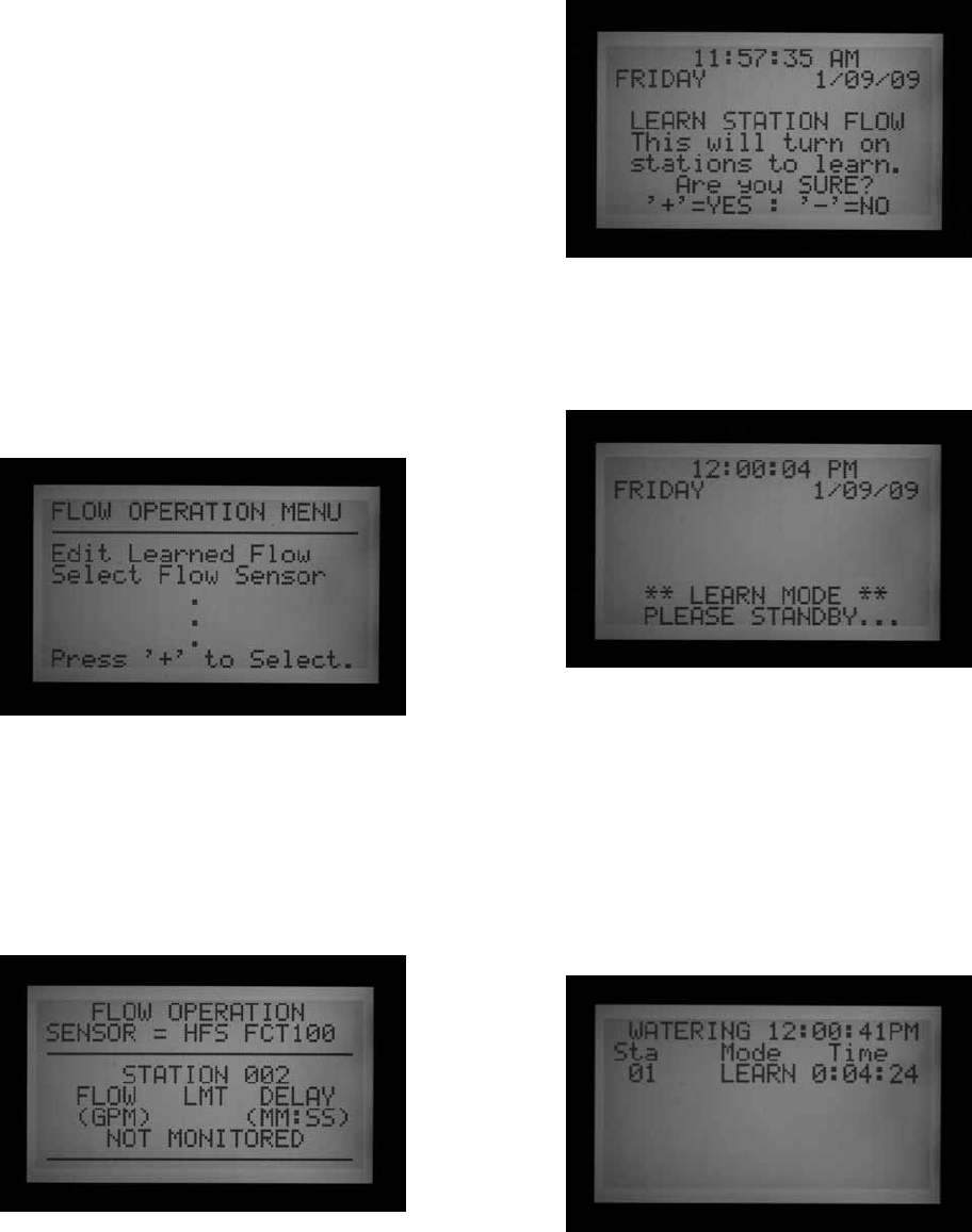
27
5. If the flow sensor selection has been changed to
NONE after learning, the display will show FLOW
NOT MONITORED. The actual flow may still be
viewed, even if all stations have been set to Not
Monitored. Station level alarm diagnostics would
not be available, but the flow will be visible.
Step 3: Preparing for Flow Learning
1. ACC will only learn flows for stations which have
run times in Automatic Programs. Verify that each
station has a run time in an Automatic Program (A
through F).
2. ACC can be taught to ignore flow monitoring for
stations which operate non-irrigation devices.
3. Turn the dial to another position, then hold the
Information button while turning back to the Set
Flow Monitoring position.
4. Select Edit Learned Flow (even if no flow has been
learned, yet).
5. Use the – button to set the non-irrigation stations to
Not Monitored. Use the up and down arrow buttons
to advance through the stations, and set any stations
necessary to the Not Monitored setting.
Step 4: Learning the Flow
1. Turn the dial back to the RUN position.
2. Press the LEARN button. The screen will display that
the controller will run the stations and it will also ask
you to confirm that you want to begin watering to
learn flow.
3. The ACC will begin watering at the lowest station
number to learn its typical flow. Normally this will be
station 01, unless it is Not Monitored or has no run
time in any programs.
It will run the station for a minimum of 15 seconds, and
then begin sampling flow at 5-second intervals until flow
has stabilized (at least 4 readings, 5 seconds apart, within
a reasonable flow range of one another). It will then store
the average flow for this station in its memory, and move
on to the next station. It will continue in this manner
through all stations which have at least one run time in
one of the Automatic Programs, and which are not set to
Not Monitored in the Set Flow Monitoring station settings.
Only stations with a run time in an Automatic Program
will be learned. Stations which are not programmed in any
Programs will not be sampled, and should be set to Not
Monitored to ensure proper operation of the flow meter.
If the station Delay setting has been changed, the controller
will run the station for Delay period (instead of the 15
second minimum) before sampling and learning flow.

28
• It may take a full hour or longer to learn flows for
an entire 42-station controller. Each station may
take from 35 seconds to 5 minutes to be learned,
depending on stability of the flow.
Step 5: Review And Edit Flow
The flow values and settings for each station can be
reviewed, and manually edited, at the Set Flow Monitoring
dial position. It is important to verify the flow settings for
each station before leaving the controller in automatic
operation.
• Turn the dial to the Set Flow Monitoring position.
• Use the up and down arrows to navigate through all
stations, and verify that they have a learned flow or a
Not Monitored setting.
• Do not leave any station with a “Not Learned” message-
either enter a flow manually, or set it to Not Monitored.
• To edit a station's flow data, turn the dial to any other
position, hold down the Information button, and turn
the dial back to the Set Flow Monitoring position.
Select "EDIT LEARNED FLOW."
• Use the up and down arrow buttons to move through
each station.
• Use the +/- buttons to adjust the flow. Each station
can be set from 0.5 GPM (1.9 LPM) to 999.5 GPM
(2770LPM) in 0.5 GPM /1.9 LM increments. Between
the highest value (999.5) and the lowest (0.5/1.9
LPM), the Not Learned and Not Monitored choices
also appear, as the +/- buttons are pressed.
You can manually replace a Learned flow with another
value, if you wish.
• LIMIT: Use the left and right arrow buttons to move to
the Limit field (LMT) to edit it, if desired.
The default Limit is always 115%, meaning the station
must exceed the flow by 15% before it will be treated
as an alarm (to prevent false alarms due to normal flow
fluctuations). 110% is the minimum possible Limit
setting, and 300% is the maximum.
• DELAY: Use the left and right arrows to move to the
Delay setting to edit it, if desired.
The default delay is 01:00 in minutes:seconds format. This
means the station’s flow will be ignored for the first 1:00
of operation, before the flow will be considered for alarm
purposes. The Delay can be set from 0:15 to a maximum of
9:59. Some delay is recommended to prevent false alarms,
particularly when stations are initially activated.
You can Copy and Paste to edit flow settings for multiple
stations with similar characteristics. Select the station
with the Flow you wish to copy and press the Copy button.
You may then Paste (Paste button) the flow value into any
other stations.
The Limit and Delay settings may also be copied and
pasted together, separately from the Flow Value.
• Review all stations to verify their flows, limits, and
delays.
• Once station flows have been learned, flow monitoring
is in effect. If the Information button is pressed during
irrigation, the actual flow will be shown, along with
the combined limit of all active stations.
• Stations that do not operate irrigation devices,
and stations that are not used, must be set to Not
Monitored to avoid false alarms.
FLOW ALARMS
When a Flow Alarm has been detected, the controller will
begin diagnostics, which can be seen in the display.
The controller will shut down all station activity for 1 full
minute. The display will show the stations as Paused
during this interval.
The controller will then test each station that was running
at the time of the alarm, individually. It will start the
lowest-numbered station that had been running, and allow
it to run for the Delay period set in Set Flow Monitoring.
After the Delay has elapsed, it will sample the flow rate, to
see if it is within the Flow Limit.

29
If the station passes (runs within the Limit), the controller
will Pause the station, and move on to test the next station
that had been running (if applicable).
If the station fails, (runs outside of the Limit), the station’s
run time will be ended, and an alarm message will be
placed in the Alarm Log.
The display will show ATTENTION: Flow Alarm if any
stations have failed the test. Irrigation (for passing
stations) continues to run normally, even if this display is
present.
Details for the stations that failed, including time of day
and Over or Underflow, will be stored in the Alarm Log
(Data History dial position).
To get detailed information about any Attention display,
turn the dial to Data History and select the Alarm Log.
After irrigation is completed, the display will continue to
show that alarms occurred, until any button is pressed.
This will usually result in multiple flow alarms since ACC
will try to restart stations after Pausing for one minute.
Since ACC can run multiple stations at once (Overlap,
SSGs, etc.), it will add up the learned flows for all stations
that are running, and compare the total to the actual flow,
in real time. If an alarm occurs with multiple stations, ACC
will enter a diagnostic mode to try to isolate the problem
stations.
All station delays must be met before the alarm will occur.
If multiple stations are running and have different delay
times set for Flow Alarm limits, the longest delay must be
met before the alarm will occur.
To view the diagnostics while they are in progress, press
the Information button. This will clear the Attention, Flow
Alarm display and show the actual status of the affected
stations. While isolation is in progress, the display will
then show individual stations in Pause status, as each
station’s flow is sampled one at a time.
ALARM LOGS
See Data History on page 38 for more information.
When a Flow Alarm is shown on the display, turn the dial
to Data History to view the Alarm Logs for an explanation
of the alarm (select Alarm Logs and press +).
The Last Event is always shown first. Press the – button to
step backwards through the logs to view them one at a time.
A Missed Irrigation report will be logged for each station
event that causes a station to shut down for Overflow or
Underflow reasons. The report will show the date and time
of the event, and which type of flow alarm occurred (Over
or Under).

30
TIPS ON FLOW ALARMS
• There is only one flow meter per ACC controller, and
controllers do not share information with one another.
If a controller with a meter “sees” flow caused by
another controller, drawing water from the same
point of connection to the water supply, the controller
will experience many false alarms, because it cannot
account for the flow. Do not combine controllers on
the same point of connection.
• Most false alarms occur because the Limit % is set too
close to “normal” or learned flow. Irrigation systems
often experience fluctuations in the amount of flow
and increasing the limit % reduces the possibility of
false flow alarms.
• The primary purpose of Underflow alarms is to protect
a Pump from deadheading, if a station has failed to
open. If a station that has learned flow is activated for
test purposes without turning on an actual valve, an
Underflow alarm may occur. This is normal.
• When two stations are running together with very
different flows, such as a high volume spray or rotor
zone running together with a low-volume drip zone,
it is possible that an alarm condition on the low flow
zone may be missed. This is because the Limit % of
the high flow zone may include the entire flow range
of the low flow zone. For example, a 40 GPM zone with
a limit of 115% needs to see 46 GPM to alarm. If it is
running together with a 4 GPM drip zone set to 115%,
the drip zone could exceed its alarm limit (4.6 GPM)
but the total would still be under the combined alarm
limit for both stations.
seTTInG ClIK™ sensor operaTIon ............................................
The ACC is capable of monitoring four individual
Clik-type sensors, in addition to the flow sensor. Typically
these sensors are weather-related sensors such as the
Mini-Clik
®
or Rain-Clik™ rain sensors, the Freeze-Clik
®
temperature sensor, or the Wind-Clik
®
wind sensor.
Each Program has three response options. OFF, SUSPEND
or PAUSE.
ACC version 4 or later is also capable of monitoring an
ET Sensor as an alarm input, and may also receive Clik
(and Flow) sensor inputs via an ICD-SEN sensor decoder.
These options are enabled with the extended features at
Set Sensor Operation for setting Locations. See Sensor
Locations on page 35 for more information.
Each sensor (1–4) will also show its current state, as
either ACTIVE (in alarm) or INACTIVE (normal or no
alarm). ACC sensor inputs are normally closed. An open
sensor is ACTIVE and shows an alarm condition.
• OFF indicates that the sensor will not respond to that
sensor. If the selection is set to "OFF," the current state
will always be shown as "Active," unless a sensor is
connected to the sensor terminals. In that case, the
state will change to "Inactive," because the circuit will
be closed. The programs will still ignore the sensor,
however, because the setting is set to "OFF."
• SUSPEND indicates that the program will stop any
current watering, and inhibit watering from beginning
should a start time pass. If a SUSPENDed Program
is resumed, it will resume where it should be in “real
time”. The stations that were missed will not irrigate,
but the Program will end at its normal time.
SUSPEND is the recommended setting for irrigation
programs when a sensor shutdown is desired.
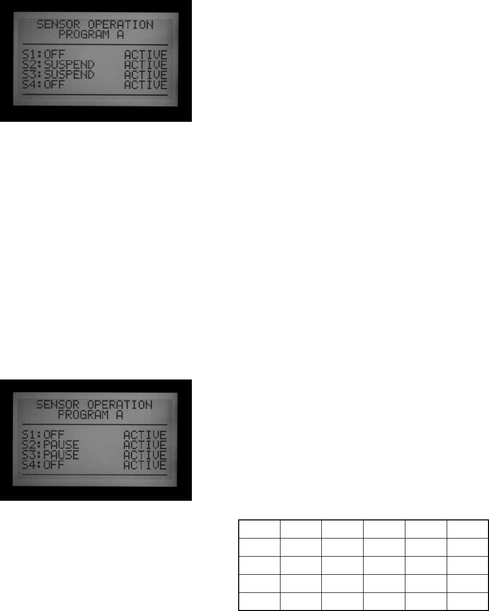
31
PAUSE indicates the controller will stop watering
until the sensor allows watering again (resets to
normal state).
PAUSE should be used with caution! Paused watering
(caused by a sensor) never expires. It is held in
memory until the sensor returns to the normal
position (normally closed), and then the watering
events will be allowed to run whenever this occurs.
This may cause unexpected behavior. This is different
from the manual Pause (pushing the Pause button),
which will time out in 30 minutes automatically
Watering that is Paused by a sensor alarm will
technically remain forever (up to 10 start times worth
will be stored), and will resume when the sensor
becomes normal or inactive again.
SET SENSOR OPERATION
1. Use the Program button to select each Program and
set the sensor responses. Each Program must have
a response set individually for shutdowns. If it is
necessary to shut down the entire controller on the
sensor input, insure that all 6 Programs (A-F) have
shutdowns set for the sensor.
2. Use the Up and Down arrow buttons to move through
the individual sensors.
3. Use the +/- buttons to select the response to each
sensor for that program.
4. Use the Program button to advance to the next
Program and set its responses.
Once a response (SUSPEND or PAUSE) has been set for a
Program, all sensor responses must either be the same, or
Off. A Program cannot be both Paused and Suspended at
the same time.
If a Pause response is set for Program A to Sensor 2, then
Pause is the only response that can be set for Program A.
Changing Sensor 3 to Suspend A will cause Sensor 2 to
change to Suspend A.
If the entire controller is required to shut down on an
individual sensor input, each program (A-F) must be
individually set to Pause or Suspend for that sensor.
Depending on how many sensors you are installing,
only change the sensor response to pause or suspend
according to sensor number one. Do not change the
response for sensor two, three and four. This will cause
the controller to engage in numerous sensor alarms. In a
different scenario, if the sensor response is changed to
pause or suspend, and the sensor has not been connected
to the corresponding sensor terminals, the state change
will remain active, indicating an open circuit. This too will
cause a sensor alarm.
: Only change the sensor responses to pause or suspend
for the Sensor inputs that are in use.
Example: If you only have one sensor, and it is wired into
sensor input number one, set the response for Suspend
or Pause, according to sensor number one. Do not change
the response for sensors two, three, and four. Leave them
set to Off.
Example #2: In this scenario, a Rain-Clik
™
is connected
to Sensor 1. It will Suspend the sprinkler stations in
programs A through E when active.
Sensor 2 has a photo sensor connected, which will
Suspend only Program F (which can be used for items like
lighting, via 24VAC relay). The Rain-Clik
™
sensor will not
affect the lighting, and the photo sensor will not affect the
sprinklers.
Programs
A B C D E
Sensor 1 Suspend Suspend Suspend Suspend Off
Sensor 2 Off Off Off Off Suspend
Sensor 3 Off Off Off Off Off
Sensor 4 Off Off Off Off Off
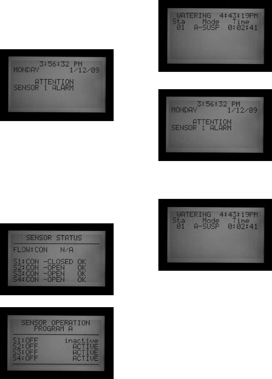
32
sensor alarms (ClIK sensors sen 1–4 only) ..........................
Whenever a sensor alarms (changes to Open from its
Normally Closed state), an ATTENTION message appears
in the display if a program response has been configured
for that sensor.
Details for each sensor alarm will be found in the Alarm
Log (Data History dial position). If the sensor response
is changed to Pause or Suspend, and the sensor has not
been connected to the corresponding sensor terminals,
the sensor will remain active, and cause a sensor alarm.
If the sensor is set to OFF for all programs, it will not
cause an alarm or ATTENTION display.
However, the state of the sensor may be observed at
the Advanced Features dial position, Utility Functions,
and then View Sensor Status. The screen will explain if
the sensor is in a closed or open state. If the sensor’s
response was set to suspend or pause in the Set Sensor
Operation dial position, the display will also show an alarm
message in this screen if the circuit is open. You can also
see the state of the sensor, even with the sensor response
set to “OFF,” in the Set Sensor Operation dial position.
If a Program configured for shutdown by that sensor was
active when the alarm occurred, it will either Suspend or
Pause as configured.
CLEAR MESSAGE
Press the + button to clear the alarm message,
and view the status of the programs. Pressing + only
clears the message, not the alarm. The display will then
show the status of Programs in response to the sensor.
Programs that were Suspended will continue to show the
stations and count down the time remaining, but will say
SUSPEND along with automatic program letter and no
watering will occur. If the sensor is reset, they will resume
watering instantly where they should be in real time.
Programs that were Paused by the sensor will show the
Program letter and Pause, and the time remaining will be
frozen . No count down occurs because events are Paused.
If the sensor is reset, the Paused Programs will resume
instantly, wherever they left off when the alarm occurred.

33
Sensor alarms have no effect on Manual Single-station
starts that are running.
Sensor alarms have no effect on Custom Manual
programs.
Sensor alarms have no effect on the Test program.
All of these types of programs are initiated by a human
operator so the sensor settings do not apply.
Note: Sensors have no effect on Surveyor generated
System Events, or System Manual Events, when
operating in Event mode. Sensor shutdowns are
designed to be transmitted from the central in Surveyor
systems. If an automatic Program (A-F) was started
Manually, it will be shut down by an active sensor that is
configured to shut down that program.
The sample display on the right shows a single active
sensor alarm in process, with a range of possible
responses. The operator has pressed the + button after
the FAULT display, to view controller status.
Station 02 was running in Program A, and that Program
has been Suspended (the seconds timer would still be
counting, but watering would be stopped).
Station 06 was running in Program B, and has been
Paused. The seconds timer would be frozen (and watering
would be stopped).
Station 05 was running in a Custom Manual program, and
the sensor would have no effect on it. Station 05 would
still be watering in Custom Manual 1.
There is no direct Override for a Clik sensor. Depending
on what needs to be accomplished, the Test program is
still available (for winterization functions) and individual
stations can still be started from the Manual position.
If a sensor is alarmed, and a Manual Program start is
attempted for a Program with a response for that sensor,
the display will show “CANNOT RUN MANUAL. A sensor is
active for this program.” That program cannot be manually
started until the sensor is reset.
If the Manual Program was running prior to the state
change in the sensor, the Manual Program will be put into
either Suspend or Pause mode. The Manual Program will
resume if the state of the sensor changes back to a closed
circuit while there is still time left on the program. If the
program that you are trying to manually run is not set to
a Suspend or Pause response for the alarmed sensor, the
Manual Program will be able to run manually.
If the Manual Program was running prior to the state
change in the sensor, the Manual Program will be shut
down and be put into either Suspend or Pause mode. The
Manual Program will resume if the state of the sensor
changes back to a closed circuit. If the program that you
are trying to manually run is not set to a Suspend or Pause
response according to that sensor, the Manual Program
will be able to run manually.
If full operations must be restored when a sensor is in
alarm, turn the dial to the Set Sensor Operation position,
and use +/- to change the sensor response to Off (by
program).
View recent alarms, or alarm history, by turning the dial
to the Data History position and selecting Alarm Logs See
Data History on page 38 for more information.
SENSOR LOCATIONS
ACC versions 4 and later support two additional types of
sensor inputs.
• ICD-SEN Sensor Decoders: Standard "clik" sensors
(as well as the Flow meter) may be connected
to ICD-SEN decoders in the two-wire path. The
controller still has 4 sensor inputs, but you may set
the location of each sensor to Controller (for the
terminals on the controller's master module) or ADM
(the decoder output module is called ADM99, and
setting a sensor to this location means the input is
assigned to a sensor decoder).

34
• ET Sensor: A Hunter model ET Sensor may be used
for certain alarm inputs. The ET Sensor is a sensor
platform, and three of its individual sensors can
be used as sensor inputs for alarm purposed to the
ACC Controller. The controller still has four sensor
inputs, but you may set the location of each sensor
to Controller (terminals SEN 1–4 on the controller's
master module) or ET (Rain, Wind, and Temp). If the
controller has a decoder output module, the third
choice ADM will also appear.
Assigning sensor locations is called "mapping" and tells the
controller where to look for each of its four sensor inputs.
Mapping sensor locations is the first step to setting up
ICD-SEN operation, and is also an optional step in setting
up ET Sensor operation.
To map sensor locations, unlock the extended features by
holding down the blue information button, and turning the
dial to Set Sensor Operation.
The Sensor Configuration screen will show the locations
of each sensor, one at a time.
Type and Style cannot be changed. Most sensors are
CLICK type and N. C. (normally closed) style.
Location: Use the down arrow to move to the Location field.
Press the + or – buttons to view other choices for the
sensor’s location.
If an ADM99 decoder module is detected by the controller,
the choices will be Controller or ADM.
If an ET Sensor has been detected and the controller has
been programmed to “Use ET Sensor” within the Advanced
Features dial position, the choices will include ET Rain, ET
Temp, and ET Wind.
Select the sensor’s Location with the + or - buttons.
Press the up arrow button to move back to the Sensor
number, and use + or – to move to the next Sensor.
Assign each sensor input that is to be used to the correct
location. When you are finished, turn the dial to another
position. If some sensors are unused, leave them set to
Location: Controller.

35
SENSOR LOCATIONS
Individual ET sensors can be used to perform alarm
shutdowns, by assigning them to the Sen 1-4 positions in
the controller. The ET Sensors will then function exactly
like “Clik” Sensor inputs. They may have Suspend or
Pause responses set by Program.
Assigning ACC Sensor 1-4 alarm functions to an ET
Sensor is done without connecting any additional wires.
The controller will use the sensor data as a virtual alarm.
ET Sensor shutdowns only apply to the controller to which
the ET Sensor is connected.
The ACC cannot shutdown other controllers as a result of
these alarms.
ET Sensor shutdowns are not instantaneous, and there
may be a delay of up to 18 minutes between an ET Sensor
alarm and the actual shutdown. If this is not acceptable, a
separate sensor (such as Rain-Clik or Freeze-Clik) should
be installed and wired directly to one of the Sen 1-4 inputs
for instant shutdowns.
The controller will automatically check the ET Sensor for
updated sensor readings every 15 minutes. If an ET sensor
causes a controller Pause or Suspend, that action will
remain in effect for at least 15 minutes until the controller
updates the readings. If the sensor returns to normal the
Suspend or Pause settings will be cancelled, as with any
other sensor.
Note: ET functions will only appear as a Location option
with the updated versions of the facepack firmware (4 or
higher), and an updated ET-ready Master Module. Once
the controller is equipped with these components, ET
must then be enabled in the programming. Turn the Dial
to Advanced Features and select “ET Functions.” Select
“ET Operation,” and press the plus button to confirm
that the controller will “Use ET Sensor.” The ET location
option will then be available to choose as a location for the
controller’s sensors.
When the controller is set to “Use ET Sensor,” more
options are also unlocked within the Advanced Features
“ET Functions” screen. One of these unlocked screens is
labeled “ET Alarm Setup.” Use the Down arrow to move to
the “ET Alarm Setup” screen. Press the plus button, and
you can adjust the shutdown levels for Rain, Temperature,
and Wind.
Rain Max: The maximum amount of rain that will be
permitted before a program is shutdown for the rest of
the day. Move to this position with the arrow keys and
use +/- to set the maximum.
The ET Rain sensor will shutdown programs after 0.02”
(0.51mm) of rainfall within an hour (this amount is not
programmable), but the program may be permitted to run
again if no more rain is detected. The ET Sensor checks for
rainfall every 15 minutes.
If the Rain Max amount is reached, the controller will no
longer attempt to run the program that day.
Temp: The air temperature can be used as a freeze sensor
to stop automatic programs, and the temperature at which
shutdown occurs is programmable (from 25° to 45°
Fahrenheit, -3.8° to 7.2° Celsius). Move to this position
with the arrow keys and use +/- to set the low temperature
shutdown.
Wind: If the optional ET Wind is installed, the wind speed
(in mph or kph) can be used to shut down designated
programs.
Reminder: Alarm settings are not in effect until the
Sensor 1-4 inputs have been assigned to them at the Set
Sensor Operation dial position, and responses have been
configured by program.

36
seTTInG proGram oVerlap opTIons ..........................................
There are three program overlap options. These options
allow you to maximize the number of stations operating
simultaneously, if the system’s hydraulics can support the
flow.
To program the Program Overlap option:
1. Turn the dial to the SET PROGRAM OVERLAP
OPTIONS position
2. Use the Up and Down buttons to navigate to
changeable portions of each display.
3. Use the +/- buttons to see and set the choices.
Once the Program Overlap Option has been selected for
the controller, individual programs can be set to Overlap
or Stack at the Set Program Start Times position.
OPTION ONE: STACK OR OVERLAP
STACK means that the programs will run in alphanumeric
order by Program letter and start time chronology. STACK
is the default.
OVERLAP means that each program will start at the time it
is scheduled to start, regardless of what else is watering.
This is true under the condition that each program is set to
Overlap. If Program A is set to Overlap and Program B is
set to Overlap, both programs will start at the time they are
scheduled to start, and run at the same time. If Program A
is set to Overlap, and Program B is set to Stack, Program
B will NOT run at the same time. Program B will not come
on until Program A is finished with its scheduled run time.
If you want multiple programs to water at the same time,
each one of those Programs needs to be programmed to
“Overlap.”
Leaving this setting in the "Stack or Overlap" position
means that each program can be set to Stack or Overlap,
individually.
The OVERLAP option does not allow for multiple stations
within the same Program to OVERLAP, or water at the
same time. Only different programs may OVERLAP and
run at the same time.
A more detailed explanation of this option can be found in
the Setting Program Start Times section of this manual.
OPTION TWO: SMARTSTACK™
SmartStack will limit simultaneous operations to the
number of stations specified here. The operator may
program as many overlapping programs as desired, and
the controller will permit overlap up to the number
specified here, and stack the rest.
• SmartStack allows from two to five stations to operate
simultaneously, before forcing additional stations into
a stacked queue.
• Use the up and down arrow buttons to move to
the number of stations allowed (after choosing
SmartStack).
• Use the +/- buttons to set the number of stations
allowed to overlap.
This is a great way to minimize the watering window
by allowing the controller to run at maximum electrical
capacity, if you have sufficient water pressure and flow to
support multiple programs.
OPTION THREE: SSG/SMARTSTACK™

37
See SSG (Simultaneous Station Group) Setup on page 47
for more information..
An SSG (Simultaneous Station Group) is a group of up
to four stations that water at the same time, for the same
duration. Any 2 to 4 stations can be placed into an SSG,
and from that time on, they will be programmed and
operated as a single unit.
Combining stations into SSGs shortens programming
time, and can also shorten watering time (by running
multiple stations at once). SSGs should normally combine
similar stations, with similar watering needs and flows, to
be used to their best advantage.
When using SSGs, the controller can electrically only
handle one SSG, two stations, and two Master Valves
simultaneously, maximum. You must choose this option if
you plan on using SSGs.
If SSG/SmartStack is chosen:
• Use the up and down arrow buttons to navigate to the
number of stations (allowed to overlap with an SSG).
• Use the +/- buttons to set the number of stations
permitted to overlap an SSG.
• Since an SSG may contain up to 4 stations, setting this
number to “1” means that up to 5 stations may run at
once (up to 4 in the SSG, plus one additional station).
Setting the number to “2” means that up to 6 stations
may run at once. Setting this to 0 means SSGs must
run by themselves and may not overlap individual
stations.
• ACC does not adjust overlap and stacking for SSGs
which have fewer than 4 stations in them… it assumes
that all SSGs have four stations, and the number of
stations allowed with an SSG applies, regardless of the
SSG’s actual size.
• If the If the Program Overlap option has been set
to SSG/SmartStack with a limit of 2, and an SSG is
activated manually, the controller will assume the
SSG may have up to 4 stations, and therefore, only 2
other stations will be permitted to run at the same time
manually.
• Once a station is programmed into an SSG that station
that may not have a run time by itself in any other
program.
CAUTION: Understand your irrigation system’s hydraulic
restrictions before allowing stations to Smartstack or
SSG/SmartStack. Overlapping stations may overtax the
hydraulics of your system. Overtaxing your hydraulics
will damage the components and result in inferior
sprinkler performance. Mixing dissimilar stations in SSGs
may cause over or underwatering of certain plant types.
SET STATION & PROGRAM NAMES
All set Station and Program names of the ACC can be
named for easy reference. This can either be setup via the
IMMS central control software, or it can be programmed
at the controller using the keypad. The Contact Info
screen can also be programmed at this position. This sets
the display which appears when the controller is turned
on, and which also appears in many of the Information
screens. The factory default setting is Hunter Industries
contact information, but it can be replaced with the
company name, telephone number, and/or web site of the
appropriate installing or servicing personnel.
ASSIGN CONTACT INFORMATION
1. Turn the dial to SET STATION and PROGRAM NAMES
position. Use the +/- buttons to select a letter,
number, or character for each letter position.
It is possible to reprogram a character right over
the existing text.
2. Hold the + or – button down continuously to advance
rapidly through all choices, including capitals, lower
case, numbers, and characters.
3. Use the left and right arrow buttons to advance
to the next character position, and select the next
character.
4. Continue until the line is complete. Use the arrow
buttons to move down and reprogram each line.
5. Turn the dial to any other position, at any time, to
save the text in the Contact Info screen.
6. Turn the dial to any other position, at any time, to
save the text in the Contact Info screen.

38
daTa hIsTory .............................................................................
Name a Program (Up to 12 Characters and Spaces)
1. Turn the dial to the SET STATION & PROGRAM
NAMES position.
2. Press the PLUS button once.
3. Use the up and down arrow buttons to select the
program you wish to name.
4. Use the plus and minus buttons to select the letter or
symbol you wish to use.
5. Press the right arrow button to advance the cursor
and then repeat, using the plus and minus buttons to
select the next letter or symbol.
6. Repeat until the name is completed.
Name a Station (Up to 12 Characters and Spaces)
1. Turn the dial to the SET STATION & PROGRAM
NAMES position.
2. Press the + twice or the – button once.
3. Use the up and down arrow buttons to select the
program you wish to name
4. Use the plus and minus buttons to select the letter or
symbol you wish to use first, press the right arrow
button to advance the cursor and then repeat using
the plus and minus buttons to select the next letter
or symbol. Repeat until the name is completed.
Shortcut: Use Copy and Paste for similar names,
and change only the characters that are unique
to the station.
5. Turn to any other dial position to save names.
This dial position allows you to view flow totals and
various logs containing important histories of all activify.
Flow totals can be viewed for
• The entire controller
• An individual program
• An individual SSG
• Or an individual station.
Controller totals are based on total measured flow.
Program, SSG, and station totals are extrapolated and
are “educated guesses” that should closely approximate
their totals, but they cannot be as accurate as the total
Controller flow. Daily totals show decimals of gallons or
liters, but weekly and larger totals round up to the nearest
whole unit of measure.
Once the flow item is selected you can then view:
• The total for today and yesterday
• Week to date & last week totals
• Month to date and last month totals
• Or year to date and last year totals
When viewing these menu selections, the left arrow button
on the facepack will operate as a Back button. Some
selections lead to another list of choices, and the Back
button will return you to the next highest level, without
having to turn the dial.
VIEW FLOW TOTALS
1. Turn the dial to the DATA HISTORY position
2. Press the plus button once.
3. Press the plus or minus button until the item you
would like to view is displayed
4. Press the down arrow button to highlight TODAY
5. Press the plus or minus button until the period you
would like to view is displayed
VIEW ALARM LOGS
1. Turn the dial to the DATA HISTORY position
2. Press the down arrow button to select ALARM LOG
3. Press the plus button to view the log
4. Press the plus and minus buttons to scroll through
the log. Alarms are logged by type of alarm, and time
and date of occurrence.
5. The Alarm Log will store up to the last 250 events
(the oldest events are replaced by new ones).

39
Alarm log items labeled “Missed Irrigation” are important,
because they have caused stations to not water when
they should. The reason for the missed irrigation will
always be indicated, as “Overcurrent” (electrical) or
“Overflow/Underflow” (hydraulic), etc. A complete list of
possible Alarm Log messages appears at the end of this
manual.
Each alarm log entry will have the exact time of the
occurrence of the missed irrigation event.
VIEW CONTROLLER LOGS
1. Turn the dial to the Data History position.
2. Press the down arrow button to select Controller Log.
3. Press the + button to view the log.
4. Use + and – buttons to scroll through the log of
Controller level events.
The Controller Log will store the last 250 Controller-level
events, with date and time stamp. These include critical
changes, such as dial turned to OFF position, Controller
time reset by user, Easy Retrieve Restore, and other
major changes. A complete list of possible Controller Log
messages appears at the end of this manual.
VIEW STATION LOGS
1. Turn the dial to the Data History position.
2. Press the down arrow button to select Station Log.
3. Press the + button to view the log.
4. Use + and – buttons to scroll through the log of Station
level events.
The Station Log will store up to 1500 events, and records
all station activity, including every start and stop of each
station. It may include alarm events if applicable.
A complete list of possible Station Log messages appears
near the end of this manual.
All logs (Alarm, Controller, and Station) replace the oldest
events when they are full, and contain only the most recent
events within the controller memory’s holding capacity.
They will never fill up, but the oldest records will be
overwritten (first in, first out, or FIFO).
All logs are cleared in computerized central systems
after the central computer uploads this data as part of its
communications. The log will then display NO RECORDS
TO SHOW and the logs will be available in the central
software, instead.
ADVANCED FEATURES
This dial position is used to verify the version and size of
the controller, and to configure and use some of the ACC
controller’s more powerful features.
A list of functions will appear at the Advanced Features
dial position, but they will depend on the devices installed
in the controller, and the version of the controller.
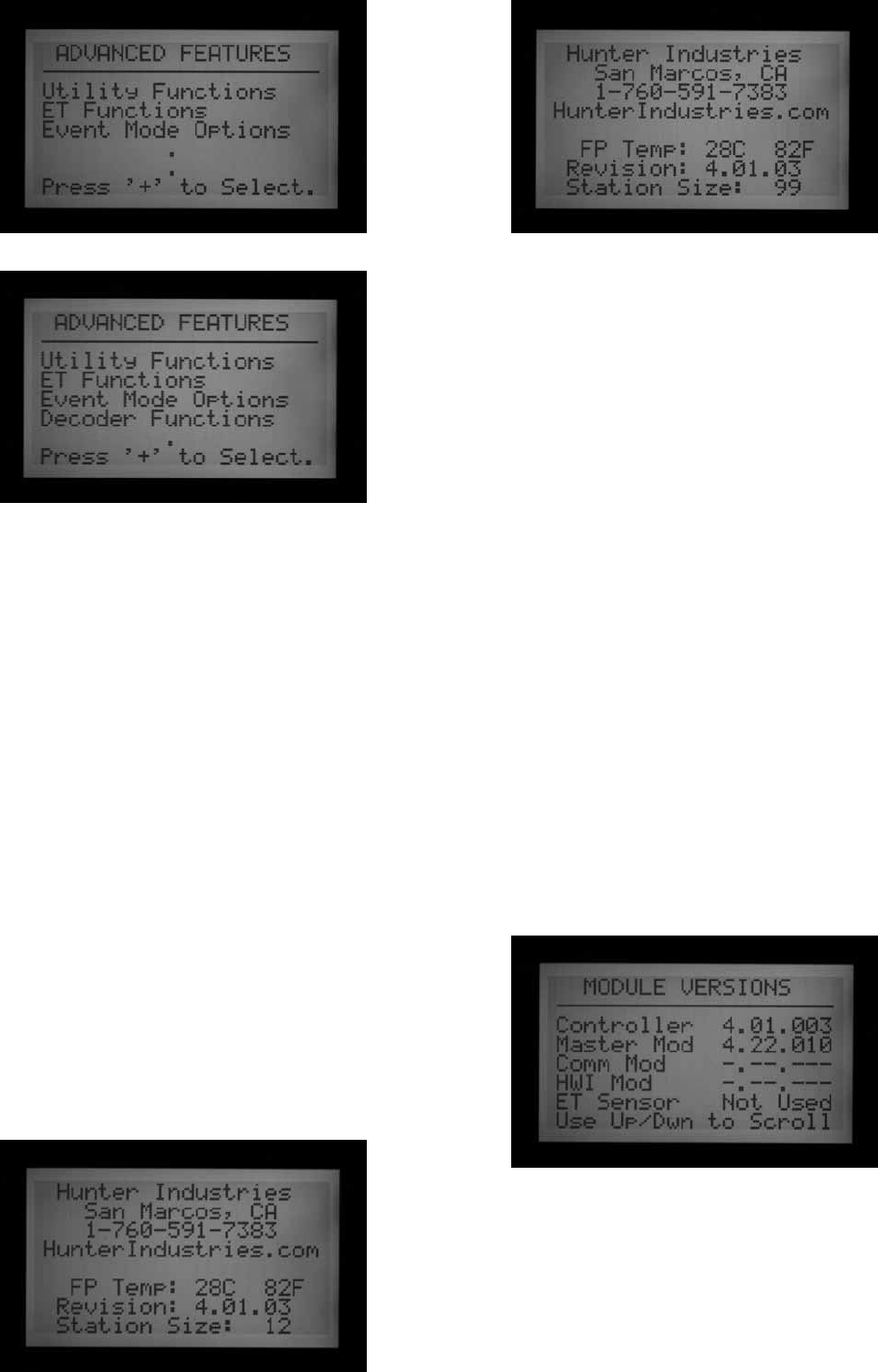
40
VIEW VERSION AND STATION SIZE
Turn to Advanced Features dial position.
Press and hold the Information button.
This will display contact information for help. This
information is programmable at the Set Station and
Program Names dial position, if you wish to change it.
FP Temp is the internal facepack temperature. It is not used
and is informational only.
The Revision number is the version of ACC firmware loaded
in the controller. You can download the latest version of
firmware from www.hunterindustries.com and flash update
the controller facepack from a laptop computer.
Please note this version number whenever asking a
question from technical support about the ACC controller.
Station Size: Shows the number of station outputs
recognized by the facepack. This does not show how many
valves are in the field, or in use. It is the count of station
output modules (number of ACM600 or AGM600 modules x
6 stations each), or it will show “99” if an ADM99 Decoder
Output module is detected.
If station size is incorrect, or shows “0” or “1”, check that
Powerlock slide is in the ON (locked) position. Check that
all station module contacts are in good order and that the
modules are fully inserted. Make sure powerlock tabs on
front of modules have good contact with the slide lock. An
incorrect station count may indicate a damaged module, if
it persists after all checks have been made.
When the info button is not pressed, the Advanced
Features may show all or some of the following items:
Utility Functions: ET Functions (only if ET Ready Master
Module and firmware are installed)
Event Mode Options: See Event Mode Options (agc,
surveyor) on page 75 for more information. (Golf only).
Decoder Functions (only if ADM99 decoder output module
is installed)
When viewing these menu selections, the left arrow button
on the facepack will operate as a Back button. Some
selections lead to another list of choices, and the Back
button will return you to the next highest level, without
having to turn the dial.
Select Utility Functions to see the following choices:
View Firmware Versions: Select to see version numbers of
all modules in use in the controller.
View Sensor Status: This will show the location and status
of the flow meter and all sensor inputs (1-4). CON means
Controller, or the screw terminals for sensor connections
inside the controller.

41
ADM means the ADM99 decoder output module, and shows that the meter or sensor input has been assigned to an
ICD-SEN sensor decoder in the two-wire path.
ET followed by a sensor name means the input has been assigned to an ET Sensor.
ET Functions are described in their own section in this manual.
Event Mode Functions are described in their own section in this manual.
Decoder Functions are described in their own section in this manual.
Common alarm (aTTenTIon) messaGes ....................................
OVERCURRENT
In a conventionally-wired controller with ACM600 or AGM600
outputs, Overcurrent means that the station has exceeded
0.56 Amps output. This indicates that either too many
solenoids are connected or the field wiring or solenoid has a
problem, causing an unacceptably high current. All solenoids
are different and not all solenoids may be “doubled” on an
ACC output. A solenoid with a holding current of 0.3 A is
acceptable, but two of them (equaling 0.6 A) would exceed
the 0.56 A max limit and cause an Overcurrent.
In decoder controllers, Overcurrent may have more
complex causes, but still indicates an unacceptable high
current on the decoder line.
The Alarm Log will indicate whether the alarm was
associated with a station number, or "ADM", referring to
the ADM99 decoder output module.
A station Overcurrent in a decoder system indicates a
high-draw condition on the output side of the decoder, to
the solenoids, usually a shorted solenoid.

42
An ADM Overcurrent message means the total draw on
the two-wire path(s) was greater than 2.2 amps, but the
ADM99 was not able to identify a particular station causing
the problem.
P/MV outputs have a max output of 0.325 A. Pump start
relays with very high current requirements may need a
dedicated transformer and an additional relay (such as
Hunter Model PSRB) for reliable operations.
Any ACC display that shows ATTENTION is indicating an
alarm or other condition that should be investigated. You
should immediately turn the dial to Data History and select
the Alarm Log to view all details associated with the alarm.
This will often reveal the real problem at a glance.
The ATTENTION message in the display will not stop
irrigation by itself, but the condition it is reporting may.
If a station is in Overcurrent, the station cannot run,
but other stations may continue running even when
ATTENTION is in the display. Press the information button
to clear the ATTENTION message if you want to see the
normal status screen.
OVERFLOW
A station has exceeded its learned flow upper limit during
irrigation. ACC totals the upper limit of the learned flow
for all running stations, and compares them to the actual
flow at the flow meter. When the combination of stations
exceeds the total upper limits (after all Delay times have
elapsed), the controller will Pause and go into alarm
diagnostic mode.

43
Alarm diagnostics consist of pausing all operations, then
starting each station that was running at the time of the
alarm individually. Each of these suspect stations has its
flow sampled alone, to see if it caused the overflow. If the
controller identifies a station as having high flow, it will
create a Missed Irrigation report and attempt to continue
watering with other stations.
POWER OUTAGE/POWER RESTORED
Power Outage and Power Restored messages often appear
one after the other, and show when AC power to the
facepack was lost and when it is restored. By comparing
the dates and times of the messages, you can determine
how long the power was off to the controller. Power Outage
and Power Restored messages are also caused whenever
the facepack is removed from the controller and replaced.
UNDERFLOW
A station has caused too little flow, indicating a possible
problem. The underflow amount cannot be set directly,
but is twice the percentage of the Limit amount set for
overflow. If a station is set 115% for the upper limit
(normal flow + 15%), then 70% will be the underflow
amount (normal flow = 30%).
eXTended feaTures ...................................................................
CONTRAST ADJUSTMENT
At the Run position, press INFORMATION button and +
button together.
The contrast of the LCD display can be adjusted from 1 to
90 to make it more visible in different light conditions. In
the Run position, press the blue Information button and
the + button at the same time for a few seconds, until the
Contrast = 50 display appears. The + and – buttons can
then be used to adjust the display for maximum visibility.

44
NO WATER WINDOW
No Water Windows prevent any automatic irrigation
from occurring during certain hours, by Program. This
can be used to protect high traffic areas from accidental
programming, or the results of Seasonal Adjust, during
busy times of day.
Start in any other dial position, hold the Information
button down, and turn the dial to Set Program Start Times.
Release the Information button.
The display will now permit programming of No Water
Windows.
To set a No Water Window
1. Use the Program button to select the program for
which a No Water Window is desired.
2. Use the +/- button to set the time for the beginning
of the No Water Window (“FROM”) in hh:mm format,
including AM/PM if applicable.
3. Use the down arrow to move to the “TO” position, to
set the end of the No Water Window.
4. Use +/- to set the end of the window, also in hh:mm
format.
The No Water Window is now set. Use the Program button
to set a No Water Window for another Program, or exit the
dial position to save the settings.
No Water Window rules
• Each Program may have a different No Water Window.
• If the operator attempts to program a Start Time that
falls withing a No Water Window, the display will flash
a warning. If the warning is ignored, the Start Time will
be saved, but will not run during the No Water Window.
If a start time has already been programmed, and the
operator attempts to enter a No Water Window which
overlaps the start time, the display will flash a warning.
• If a Program starts at a “legal” time, but runs past
the beginning of a No Water Window, irrigation will
be stopped (display will show “Suspend”). If the No
Water Window ends and the program still has time
left, the irrigation will resume where it should be for
that time of day. Any irrigation that was suspended
during the No Water Window will be missed.
Likewise, if a start time has already been programmed
and the operator attempts to enter in a No Water
Window, and the start time falls within the No Water
Window time period being set, the display will flash a
warning as well.
• Programs that continue into a No Water Window
because of Cycle & Soak settings, or because of
Seasonal Adjust settings, will also be suspended.
However, there will be no warning in the display
when these changes are made at Cycle & Soak or
Seasonal Adjust.
• In version 4 and later, an ATTENTION message will be
displayed whenever a Non-Water Window violation
causes watering to be missed, and the missed stations
will be listed in the Station Log.
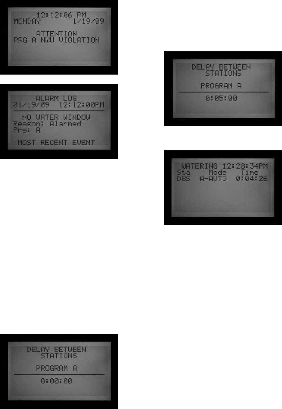
45
DELAY BETWEEN STATIONS
Delay between Stations allows the operator to set an
automatic delay between sequential stations by Program,
from 1 second to 6 hours. The original purpose of Delay
between Stations was to provide time for slow-closing
valves to shut down before the next valve was started, and
these delays are usually set in seconds. The Delay can also
be used to allow time for a well or pump reservoir to refill
before the next station begins.
In the ACC, Delay Between Stations can be set by Program,
which can be very useful when only certain types of
stations (large rotor zones, low flow drip) are grouped
within a program.
Start in any other dial position, hold the Information
button down, and turn the dial to Set Station Run Times.
Release the Information button.
The display will now permit programming of Delay
between Stations.
To set a Delay
1. Use the Program button to select the Program for
which the Delay is to be set.
2. Use the +/- keys to set the delay in h:mm:ss format.
Use the left and right arrows to move through the hour,
minutes, and seconds fields until the delay is set.
The Delay Between Stations for the Program is now set.
Use the Program button to set a select another Program,
or exit the dial position to save the settings.
Delay Between Stations rules:
• Delays occur equally between all stations in a
Program.
• Delays do not occur before the first station, nor after
the last station.
• Delays may cause a Program to run into a No Water
Window, and no warning will be flashed. The No Water
Window will still prevent any irrigation during the No
Water Window times.
• The delay time is not included in the "Total Program
Runtime" screen, or the "Total Station Runtime"
screen.
P/MV STYLE (NORMALLY CLOSED/NORMALLY ON)
The ACC controller is designed to work with Normally
Closed master valves (MV). The P/MV Style setting allows
you to reverse this operating feature for very specialized
applications, by making Normally Closed valve "on" all the
time, except when a station is running. Then the normally
closed master valve will turn off and close.

46
This is not a normal irrigation setting but may be useful for
some specialized applications. The ACC controller is NOT
designed to operate with true Normally Open valves.
ACC’s two Pump/Master Valve outputs (labeled on the
master module terminals as P/M1 and P/M2) are preset
to Normally Closed (NC), but either of them can be set to
Normally Open (NO).
A Normally On P/M setting means the station output is
always hot (providing 24 VAC) until an associated station
is activated, at which time the P/M output turns off.
• Start in any other dial position, hold the Information
button down, and turn the dial to Set Pump Operation.
Release the Information button.
The display will now permit selection of P/MV1 and P/MV2
settings.
To change the Normal condition of P/M outputs
Use the +/- keys to set P/M1 to NC or NO. Use the right
arrow to move to P/M2, and use +/- to change it between
NC or NO.
The Location field is only changeable in Decoder
controllers. In a decoder controller, the Location field may
be changed from “Controller” to “ADM” (decoder module).
If you select ADM as the Location, this indicates that the
Pump or Master Valve is connected to a decoder that has
been programmed to be the Pump or Master Valve
decoder,
and the decoder is connected to the two-wire path.
If a P/M output is set to NO, the green light on the Master
Module for output activity is always lit, until a station with
that P/M is activated. Then the station activity light will go
out, to show the output has shut off.
SETTING THE FLOW SENSOR SIZE AND TYPE
ACC’s Real Time Flow Monitoring is designed to work with
Hunter HFS flow sensors. It is necessary to tell ACC what
size fitting the HFS has been installed into, so that flow can
be measured accurately for pipe size.
The ACC may also work with other standard types of flow
sensors or meters available, but additional calibration is
required. These sensors are set up under the selection
“OTHER”. One known compatible sensor is Data Industrial
Model IR-220B (also sold as Hunter model GENDATFL),
and other Data Industrial sensors with the same signal
characteristics should perform satisfactorily.
The HFS must be installed into one of the mating FCT
fittings designed for that purpose. At this time, there are
7 possible sizes ranging from 1” diameter (25 mm) to 4”
(100 mm), in two different classes of pipe, according to
the following table.
Pipe
Size
Metric
(rounded)
Class Fitting
Model
Minimum
Flow
(GPM/LPM)
1" 25mm Schedule
40 (white)
FCT100 6/22
1.5" 38mm Schedule
40 (white)
FCT150 13/49
1.5" 38mm Schedule
80 (gray)
FCT158 13/49
2" 50mm Schedule
40 (white)
FCT200 20/75
2" 50mm Schedule
80 (gray)
FCT208 20/75
3" 76mm Schedule
40 (white)
FCT300 50/189
3" 76mm Schedule
80 (gray)
FCT308 50/189
4" 100mm Schedule
80 (white)
FCT400 60/227
The HFS cannot read flow below the minimum rate (in
GPM/LPM) listed for the pipe size.
After connecting the flow meter according to the HFS
installation instructions, the Pipe Size must be entered
into ACC for the measurements to be accurate.
1. To calibrate flow sensor readings: Start in any other
dial position, hold the Information button down,
and turn the dial to Set Flow Monitoring. Release
the Information button to view the Flow Operation
screen.

47
2. Use the down arrow button to move to Select Flow
Sensor, and press the + button to choose it.
3. Use the + button to advance through the pipe
sizes shown in the Fitting Model column until the
correct size is displayed. The last selection after the
standard FCT models is OTHER.
4. If the controller has a decoder output module, and
the flow meter will be connected to an ICD-SEN
sensor decoder on the two-wire path, use the down
arrow to move to Location. Change Location to ADM
with the + or - buttons.
5. Exit the dial position to save the settings, unless you
have selected OTHER.
Additional settings for OTHER
Most other brands of flow sensor require two settings
for calibration, the K-factor and the Offset. The correct
settings for these values are found in the sensor
manufacturer’s documentation, and they are based on the
pipe type and size.
1. Consult the “Other” flow sensor’s documentation for
the correct values for a given pipe size.
2. If Other is chosen, use the down arrow to move to
the K-factor setting.
3. Use the right arrow to skip over any places that need
to be left at “0”.
4. At any digit which needs to be changed, use the
+/- buttons to enter the digit. Then move to the
next place and repeat until the correct K-factor is
displayed.
5. Use the down arrow to move to the Offset value, and
repeat.
When the correct values are shown for both K-factor and
Offset, exit the dial position to save the settings. The flow
sensor will now be calibrated for the pipe size.
SSG (SIMULTANEOUS STATION GROUP) SETUP
Turn the dial to the Set Program Overlap Options position
See SETTING PROGRAM OVERLAP OPTIONS on page 36 for
more information.
SSGs are groups of 2, 3, or 4 stations which are grouped
together electronically. They will then all run together and
are programmed as a single unit. Up to 20 SSGs can be
created in the ACC controller.
This powerful feature can be used to balance flow, shorten
the water window, simplify programming, and expedite
common tasks. SSGs can be included in automatic
programs or custom manual programs, and can be started
manually from controller at any time. They can also be
named to make using them easier.
SSGs are not required to operate the ACC controller. They
are a valuable extra feature for advanced users.
See SSG Rules on page 49 for more information.
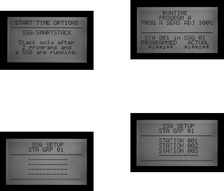
48
To create and use SSGs: In order to create and use
SSGs, the controller must first be placed into the
SSG/Smartstack mode.
1. Turn the dial to the Set Program Overlap Options
position.
2. Use the +/- buttons to select SSG/SmartStack.
3. Turn the dial to any other position to save the setting.
4. Hold down the Information button, and turn the dial
back to the Set Program Overlap Options position.
5. Release the Information button, and the SSG Setup
screen will appear.
6.
The first possible SSG will be presented as STA GRP
01, and will display 4 rows (dashed lines in a new
installation, station numbers if they have already
been programmed). Each line is for a station that can
become a member of the SSG.
7. Use the down arrow to go to the first dashed line (or
existing station number).
8. Use the +/- buttons to select a station number. Once
a station has been assigned to an SSG, it is no longer
available for other SSGs, and will not appear as one
of the choices while pressing + or – in other SSGs.
Once a station has been programmed into an SSG,
this station will no longer be available individually as
a single station outside of the SSG. If a station in an
SSG is viewed individually in the Station Run Times
position, the run time will be filled with asterisks
(**:**:**) and the screen will show the SSG to
which the station belongs, instead. No run time may
be entered for an SSG station individually. If a station
has an individual run time in a program, that station
will not be able to be programmed into an SSG.
While entering stations into an SSG, the stations that
already have a programmed run time will be skipped
over, and the only stations with no run time will be
shown.
9.
Use the down arrow to go to the next station line, to
add another station to the SSG.
10. Include 2, 3, or 4 stations in the SSGs as needed. (It
is possible to create an SSG of only 1 station, but this
defeats the purpose of the SSG- single stations may
be mixed in a program with SSGs, as long as they are
not SSG members.)
11.
When the SSG is complete, you can create another
SSG without exiting the dial position.
12. Use the up arrow to move back to the STA GRP
location.
13. Press +/- to select another STA GRP number.
14. Continue to add stations and create SSGs until all
desired groups are created and populated.
15. Turn the dial to any other position to save. The SSG
groups that you have programmed can be found
within the “Set Station Run Times” position after
the last station number in the controller, or by going
backwards from station 1. The same is true for the
“Manual Operation” dial position (the SSG groups
will be found after the highest-numbered individual
station).
You may run a station individually, even if it has been
programmed in an SSG, by selecting the “One Station”
manual in the Manual Operation dial position, and then
selecting the specific station you would like to run.
You may also run a station individually that has been
programmed in an SSG by using a remote control.
EDIT AN SSG
Changing or deleting an existing SSG is done from the
same Extended Feature.

49
1. Hold down the Information button, and turn the dial
back to the Set Program Overlap Options position.
2. Release the Information button to view the SSG
Setup screen.
3. The first SSG will be displayed and highlighted.
Change to a different SSG by pressing + or – to move
through all SSGs.
4. When the SSG to be edited is selected, use the down
arrow to move to the stations area of the display.
5. To replace a station in an SSG (with a different
station): Highlight the station to be replaced. Press
the + or – buttons to change the line to the new
station number.
6. To delete a station in an SSG (without replacement):
Highlight the station to be replaced, and use the + or
– buttons until the dashed line appears. This choice
appears between the highest numbered station,
and the lowest station remaining which has not
been assigned to an SSG. Leave the dashed line and
move to a different field in the display with the arrow
buttons.
7. To add a station to an SSG: Use the down arrow to
move to the next blank dashed line.
8. Use the + or – to select the station to be added.
Once all 4 lines are full (contain station numbers or
names), the SSG is full and no more can be added.
ADDING AN SSG
Enter the SSG Setup mode (Information + Set Program
Overlap Options).
The first SSG will be highlighted.
Use the + button to advance through all existing SSGs,
until the next unused SSG appears (having all dashed lines
with no station selections), and select stations as desired.
Once the controller is in ACC Setup mode, all 20 SSGs are
available, whether they are used or not.
DELETING AN SSG
Technically SSGs are never deleted, as there are always
20 available.Instead, simply select the unwanted SSG,
and delete the stations contained in it until no stations are
listed under the SSG name.
SSG FLOW DATA
SSGs use the combined learned flow data for all their
member stations. They do not have a flow assigned
directly to them. If the stations in an SSG are edited
(added or deleted), the flow for the whole SSG will change
by the amount of that station.
SSG RULES
A station which is included in an SSG may still be started
separately at the Manual Operation function or from the
ICR remote control.
A station which is included in an SSG is not available for
individual placement in automatic Programs, while the
controller is in SSG/SmartStack mode.
In the Set Station Run Times position, individual stations
which are SSG members will be shown, but their run times
will show as *:**:** and cannot be changed. The display
will show the number of the SSG to which they belong, and
the run time for the SSG should be changed instead.
SSGs are shown at the end of the station list when setting
run times, and most other functions. For example, in a 12
station controller, the stations would be displayed as 1, 2,
3…12 followed by SSG 01, SSG 02, etc.
Beginning from station 01, use the – button to see the
SSGs quickly (like going backward from the beginning of
the list to the end of the list).

50
CUSTOM MANUAL PROGRAM SETUP
Press the INFORMATION button and turn the dial to
Manual Operation.
Custom Manual programs are “preset” irrigation
sequences which do not run automatically, but can be
started at any time from the Manual Operations position.
The ACC permits up to 4 Custom Manual programs.
Custom Manual programs can be used for many
specialized functions that are commonly started from the
controller, to save tedious setup each time the function is
needed. They also permit very flexible programming for
unusual applications.
To create a Custom Manual program: Press the Information
button, and turn the dial the Manual Operations position.
The Custom Manual setup screen will appear.
The screen will show a setup form for Custom Manual Prg 01.
To set up a different Custom Manual, press the Programs
button to advance.
To continue setting up the selected Custom Manual, press
the down arrow to advance to the first Event.
Events can be stations, SSGs, or even Delays. Events are
the order in which items will run.
Use the + or – button to choose a station or SSG for the
first event.
Use the right arrow to move to the duration (time) for the
event. This can be completely different from any run times
that item may have in regular programs (A-F).
After run times are entered, the “Use Cycle and Soak?”
question will appear, if the station or SSG has been
programmed to use Cycle and Soak with the “Y” selected.
If you want the stations or SSGs to use their normal Cycle
and Soak settings (if applicable), leave the option set to
“Y.” If not, change the “Y” to “N” with the + or – buttons.
For specialized applications where longer run times are
desired (such as leaching), leave the Use Cycle and Soak
to N and the station or SSG's Cycle and Soak settings will
be ignored.
Use the down arrow to move to the next event, and
continue until the Custom Manual program is complete.
CUSTOM MANUAL RULES
• Delays can be inserted as Events. Use the + or –
buttons (the – button is often closer) to scroll through
the stations and SSGs to DELAY (occurs below Station
01, and above the highest numbered station or SSG).
Set a time for the delay as though it were a station.
• Stations and SSGs may be mixed in a Custom Manual.
• The same station (or SSG) may be included multiple
times in a Custom Manual.
• Stations (or SSGs) may run in any order in Custom
Manuals, unlike automatic programs.
• Custom Manuals are always run in an overlapping
mode, because they are manually started.
For example, if an automatic program, manual, or ICR
command is already running, the custom manual will
run at the same time within the six station maximum
rule. If there are already three stations running,
and the first event in the Custom Manual is an SSG,
the screen will explain in the Manual Operation dial
position that it cannot run the Custom Manual because
the max number of stations is already running.

51
START A CUSTOM MANUAL
• Turn the dial to the Manual Operation position.
• Use the Program button to select the Custom Manual
program (Custom Manual programs will appear after
the A through F selections).
• Turn the dial to Run, to start the Program at the
beginning. The display will show “To Manually Start
Station 01…”, but this only indicates that it will start
at the beginning of the program. Each station will run
for its programmed time, and stations with no run
time in the selected program will be skipped.
• To start later in the Program (at a higher numbered
station), use the down arrow to move to the station
number, and press the +/- buttons to advance to the
desired station (or SSG) number.
• Turn the dial back to Run to start the Program at the
desired station. The Program will begin at that station
and continue until the last event, then stop.
The display will show #-CUST under Mode, to show why
the stations are running.
TEST PROGRAM
Press and hold the Programs button
ACC has a quick Test program which will run all stations
for a selectable period of time, in numerical order. The Test
is an easy way to walk through every station in the system
to verify proper operation, or perform diagnostics. It also
features a quick advance for stepping through stations
with the arrow button.
Test does not run SSGs or programs. It activates each
individual station output in turn.
Run a Test Program
• Turn the dial to the Run position.
• Press and hold in the Programs button for
approximately 3 seconds.
• The Test Program screen will appear below the time/
date display.
• The screen will show Station 01 (and its name, if
applicable) and the run time field will be highlighted.
• To start the Test Program on a station higher than 01,
use the Up and Down arrow buttons to advance the
starting station number.
• Use the +/- buttons to set the test run time, in mm:ss
format. The maximum run time in Test mode is 15
minutes. The minimum run time for Test is one second
in conventional controllers and 15 seconds in decoder
controllers.
• Use the right and left arrow buttons to move between
the minutes and seconds fields to set the universal
test time, and then wait a few seconds.
• The Test program will begin running in 3 seconds if
no further buttons are pressed. Each station will show
the time remaining in the display.
• Once the Test program is running, the stations can
be advanced or reversed without waiting for the run
times to complete. Press the right arrow button to
step up one station immediately. Press the left arrow
button to back up one station (this will restart the
previous station with a new Test run time).

52
• The Test Program will try to start ALL stations counted
by the controller. If you are running a Test Program on
a decoder controller, the Test Program will attempt to
activate all 99 stations. If you do not have 99 stations
installed in the field, this may cause multiple alarms
for decoder stations that are not present and do not
respond.
EASY RETRIEVE™ BACKUP
Press the INFORMATION and Programs button at the same
time with the dial set at Run position).
This saves the complete controller setup, including
programs, start times, run times, etc., in a safe part of the
controller’s memory.
Once this info is saved, it can be recalled and the
controller can be restored to that condition regardless of
what has been programmed or altered since.
Remember to save an Easy Retrieve backup after the
controller is programmed and fully operational. If other
people make unauthorized changes or don't know what
has been done to the controller times, the Easy Retrieve
restore functioncan be used to restore the controller to
the original program set up.
• To save an Easy Retrieve backup: First, make sure
the controller is in the desired state of programming,
including Days to Water, Start Times, Run Times,
names, etc.
• Turn the dial to the Run position.
• Press the Information and the Programs buttons at the
same time.
• The Easy Retrieve save screen will appear.
SAVE will be highlighted. Press the + button to save the
program, and a confirmation message will appear. The
Save can still be cancelled with the – button, or press + to
complete the save. The backup will be complete if + is
pressed.
• To Restore an Easy Retrieve program: Turn the dial to
the Run position.
• Press the Information and the Programs buttons at the
same time, and the Easy Retrieve screen will appear.
• Use the down arrow button to move from Save to
Restore.
• Press the + button to Restore. A confirmation
message will appear.
• Press – to cancel the Restore, or + to continue with it.
• If + is pressed to confirm, the original saved Easy
Retrieve program will replace the existing controller
information.
• If you wish to make a new backup, leave Save
highlighted and press + to create a new backup. This
will completely replace the original Easy Retrieve
backup with the new one.
• If no backup has ever been made, the Restore option
will not be shown until an Easy Retrieve backup has
first been saved.

53
one TouCh manual sTarT .........................................................
One-Touch Manual Program Start with Station Advance
(right arrow button)
With dial in Run, press and hold the right arrow button
approximately 3 seconds to enter Manual Program start
mode.
Choose desired program with Programs button, and wait.
Program will start in approximately 3 seconds, if no other
buttons are touched. The controller will run the selected
program until it is finished. Note that the program will
still run automatically at the scheduled start time (if it is a
watering day).
You have the option of beginning on a higher-numbered
station or SSG, if you do not wish to run the whole
program.
Before the program starts, use the down arrow button to
move to the station number in the display.
Press the + button to move to a higher-numbered station
or SSG, and wait approximately 3 seconds.
The program will begin on that number. It will not “circle
around” and water the lower numbered stations. It will
begin at the number you selected, continue to the end,
and stop.
Once the Program is started, press the right arrow again
to advance, to the next highest-numbered station (or
SSG) in the Program with a run time. You may continue to
advance through all the stations/SSGs in a Program.
• If the controller is running that last (highest
numbered) station or SSG with a run time in the
selected program, and the right arrow button is
pressed again, the station will be stopped and no
new stations will be started (the program will have
completed).
• The Station Advance feature does not work in reverse.
You may advance, but you may not step back down
through the lower numbered stations and SSGs.
• SSG groups are advanced as a group. If the SSG
running contains 1, 2, and 3, and the advance button
is pressed, 1, 2, and 3 are all stopped and replaced by
the next station or SSG in the program. If the next item
was an SSG containing 3, 4, and 5, then stations 1,2,
and 3 will be replaced by stations 3, 4, and 5.
• You may start multiple programs with the One-Touch
Manual Program Start. Start the first program and
wait for it to begin. Then press and hold the right
arrow again. Until you change programs, the display
will show "CANNOT RUN MANUAL. This program is
already running."
• Press the Programs button to select another program
and wait about 3 seconds for the program to begin.
• Stack and Overlap settings are observed in Manual
Starts. You may only run multiple programs manually
if they are all set to Overlap.
manual operaTIon dIal posITIon.............................................
This dial position enables immediate operation of either
a single station (including P/MV1 or P/MV2), or an
Automatic Program. It can also be used to start an SSG or
a Custom Manual Program (if these optional items have
been created).
• Turn the dial to the Manual Operation position.
• Use the +/- buttons to switch between Manual
Program, or Manual One Station.

54
To completely stop all irrigation, including any stations
which are already running, turn the dial to the System Off
position.
Within a few seconds a large OFF will appear in the display.
Any stations which were running will be shut down, and no
new automatic irrigation will be allowed to start.
sysTem off .................................................................................
The controller cannot run automatic programs with the
dial in the Off position. However, ICR remote controls will
still operate stations manually when the dial is in OFF.
“Program” will allow an entire Program to be run
immediately, and will also allow the Program to be started
at any station (to run from that point to the end).
• Use the Program button to select the Program
(Custom Manual programs will appear after the A
through F selections).
• Turn the dial to Run, to start the Program at the
beginning. The display will show “To Manually Start
Station 01…”, but this only indicates that it will start
at the beginning of the program. Each station will run
for its programmed time (including Cycle and Soak
settings), and stations with no run time in the selected
program will be skipped.
• You may change the run time for the station selected
by using the +/- buttons to set the desired run time in
h:mm:ss format. Changing the run time in this screen
will only affect the station that is currently being
displayed; it will not change other station’s run times
in the manual program. Changing the run time in the
“Manual Operation” screen will not change the run
time for that station in the “Set Station Run Times”
screen, which applies to the programmed automatic
run time for that station.
• To start later in the Program (at a higher numbered
station), use the down arrow to move to the station
number, and press the +/- buttons to advance to the
desired station (or SSG) number.
• Turn the dial back to Run to start the Program at the
desired station. The Program will begin at that station
and continue until the last event, then stop.
Manually started Programs and Custom Manual programs
do not run for multiple start times. Programs started at
a higher station than their beginning station do not start
over at the beginning; they run from the designated station
and run to the end, then stop.
“Manual One Station” allows any individual station, SSG,
or P/MV to be started.
• Use the +/- keys to select a station. Any SSGs will
appear at the end of the station list.
• From the Station 01 position, the – button will go
immediately to the highest numbered station, or the
SSGs. The Manual One Station function is the only
way to activate P/MV outputs by themselves, without
an associated station. You can assign a run time from
1 second to 6 hours to either of the P/MV outputs for
manual watering or other purposes.
• Use the left and right arrow buttons to move between
the hours:minutes:seconds fields.
• Use the +/- buttons to set the desired run time in
h:mm:ss format.
• Turn the dial to the RUN position, and observe the
display. The station or SSG will begin irrigating within
a few seconds.
The display will always show a list of items running, why
they are running, and the remaining time for each item.

55
It is also possible to set a programmable period (from 1 to
31 days) for Off, after which the system will automatically
return to automatic irrigation. This is useful for halting
irrigation when weather fronts or conditions are expected
to persist for several days.
To set a programmable Rain Off duration: turn the dial to
the Off position.
While the controller is in the OFF mode, press the + button
and hold for approximately 3 seconds.
The Days Left: xx display will appear. Release the + button,
and then use the + or – button to set the desired number of
Days Off before automatic irrigation will resume.
Turn the dial back to Run immediately (the days off setting
will time out if it is left more than 5–6 seconds).
The display at the Run position will then show the number
of days for the Off setting. This display will count down
each day, showing the remaining days until automatic
irrigation will resume.
raIn off ......................................................................................
reseT ..........................................................................................
The ACC controller can be reset, erasing most
programmed information. There are 5 different levels of
Reset command available, but once any of them is chosen,
the information will be permanently erased.
These operations are not reversible!
Reset should only be performed if:
a) a “clean start” is desired for programming purposes, or
b) if directed to do so by Hunter Technical Services as a
troubleshooting technique.
To Reset the ACC controller: Turn the dial to the Run
position.
Press and hold the Programs button, and at the same
time press in the recessed Reset button with the tip of
a ballpoint pen. Release the Reset button and continue
holding the Programs button until the Reset Memory
screen appears (then release the Programs button).

56
The display will show the following Reset options:
• Programs: Erases Day schedules, start times, and run
times.
• Flow Totals: Clears the running flow total histories
(they will restart with 0.0 for all entries), only.
• Logs: Clears alarm, controller, and station logs, only.
• Names: Clears all user-programmed names, including
Programs, Stations, and SSGs.
• All Data: Clears all of the above items, and controller
returns to original out-of-the-box programming state.
• Use the up and down arrows to highlight the desired
type of Reset .
• Press the + button to select it.
• A confirmation message will appear. If + is pressed
again, the selection will be reset.
None of the reset functions will erase the Easy Retrieve‘
“backup”, if one has been made.
deCoder operaTIons (aCC99d VersIons) .................................
Status LEDs
2-wire path
terminals (1-6)
Programming
Port
CONNECTING THE 2-WIRE PATHS
1. Turn Controller power OFF.
2. If the decoder output module is a replacement for an
existing decoder installation, simply reconnect the
2-wire paths to their screw terminal assignments. If
more than one path has been used, attach the original
red and blue pairs to the red and blue terminals with
the appropriate number.
3. If this is a new installation, or conversion of a
conventional controller to decoder operations:
• Route the red and blue wire paths from the field
up through the wire openings or conduit into the
controller wiring compartment.
• Connect the red and blue 2-wire paths to the decoder
output screw terminals.
• There are two rows of screw terminals on the decoder
output module, one red and one blue, labeled
1-2-3-4-5-6. Each numbered pair represents a
possible 2-wire path to the field (some systems only
use one pair, others may use all 6).
• Connect the red wire from a twisted pair to a
numbered red terminal, and connect the blue wire
to the blue terminal with the same number. Do not
connect more than one wire to any of the terminals.
Do not mix red from one pair with the blue from
another pair. Keep each pair separate, red to red and
blue to blue, until all pairs are connected to their
numbered terminals.
4. Turn controller power back ON and test. The Module/
Line Activity LED on the decoder output module should
light up red for a few seconds. The red light should
then disappear and the Line Status LED on the decoder
output module should be a steady green, with no other
line activity or stations running.

57
Blank (Off) : Normal.
Solid Red: Problem in decoder out put
module
Blinking Red: A decoder is faulted
(possible solenoid short or damage), or a
decoder fails to respond
Red at power-up then goes out.
Blinks Green when watering
any station.
Blinks Red, Overload or short on
2-wire path.
Solid Red, problem in decoder
output module.
Green when communicating down
2-wire path
Amber when communicating though
Programming Port
Green: Normal
Blinking Green or Off: Problem in
decoder output module.
The decoder output module should now be completely
installed and ready for normal operations.
STATUS LIGHTS (ADM-99 OUTPUT MODULE)
The ADM-99 decoder output module has four status LEDs
which can be helpful with setup and diagnostics. The
replacement upper deck label is used to label these lights.
Place the decoder light label over the controller deck lid
windows, not directly on the ADM99. The holes in the
replacement label should allow lights to shine through.
The decoder label aligns with station numbers 5, 2, 12,
and 9.
DECODER PROGRAMMING
Each decoder is programmed with station address(es)
at the controller, before installing it in the 2-wire path.
The decoder output module has two holes in the lower
right called “Programming Port.” Program the station
number(s) into the decoders, and then write the station
number assignments on the metallic tag on the decoders.
Before programming any stations, you should have an
exact plan on paper for the location of each decoder and
station in the system.
ICD decoders are available in 1, 2, 4, and 6-station sizes,
and they may be mixed in the same system. However,
the numbered station assignments for each decoder will
be filled in automatically, depending on the size of the
decoder.
Do not program the same station number into two
different decoders!
When programming a 2, 4, or 6-station decoder, you only
assign a station number to the first station output. The
other stations are automatically filled in by the decoder in
numerical order, depending on the decoder size.
For example, a 4-station decoder (ICD-400) will activate
stations 20, 21, 22, and 23.
In programming, the decoder is assigned “20”. Because it
is a 4-station decoder, it will automatically fill in the other
stations with 21, 22, and 23.
Single-station decoders (ICD-100) only receive the station
number that is selected for them.
PROGRAM DECODER STATIONS
1. Turn controller power ON.
2. Insert the stripped end of the red wire from a decoder
into one of the two holes labeled Programming Port on
the lower right of the decoder output module.
3. Insert the blue wire from the decoder into the other
Programming Port hole. Do not let the wires touch
each other!
4. Turn the controller dial to the hAdvanced Features
position.

58
5. The display will show “DECODER FUNCTIONS,” at the
bottom of the selections. Use the down arrow button to
select Decoder Functions. Press the + button to select.
6. The Decoder Functions screen will appear, with
“Program a Decoder” highlighted.
(The other functions are explained in detail in the Special
Decoders Section). Press + to select. The display will
then show “Checking for a decoder…” as it attempts
to communicate with the decoder in the Programming
Port. The Communicating LED on the output module
will light amber when the programming port is in use
(communicating with a decoder.)
7. The decoder output module will check for the presence
of a decoder. If the wires are correctly inserted into
the Programming Port, a screen will appear with the
decoder settings.
8. If a decoder is recognized, the display will show
current settings for the decoder. If the decoder
is recognized as a station decoder, the size of the
decoder (1, 2, 4 or 6) will show in the DEC TYPE area.
Decoder type can be Station or Pump. Most decoders
in most systems are type “Station”, which activate
irrigation solenoids.
• Use the up and down arrow buttons to highlight
different settings, and the + and – buttons to change
them.
• Station number (When Dec Type is “Station”) can be
any number from 001 to 099. Do not allow more than
one decoder in a system to have the same station
number!
• Power Factor is normally 2 and this is correct for
most installations. Possible range is 1 to 5. In certain
situations it may be necessary to change this value
to hold in heavier solenoid loads. These values
will change the duty cycle of the power supplied to
the decoder from 10 to 38% in approximately 7%
increments. This value should not be adjusted unless
absolutely necessary as it may adversely affect the
performance of the rest of the system.
• Inrush is normally set to 3 and this is correct for most
installations. Possible range is 1 to 9. These values
will change the timing of the initial powering of the
solenoid from 0 to 90 mS in 10 mS increments to aid
in activating solenoids and relays with higher inrush
current requirements.
9. When the decoder settings are correct, push the
Program button to send them to the decoder. The
display will show “Programming…” for a few seconds
until the information is downloaded into the decoder.
10. If the programming (of the decoder) is successful,
the display will show “PROGRAMMING COMPLETE”
and prompt for another decoder. Using a ball point
pen, write the station numbers for each output
of the decoder on the aluminum label for later
reference. If the decoder has been accidentally
disconnected or malfunctions, the display will show
“Programming Failed!” This means the decoder was
not programmed (check connection, and try again).
11. When all decoders and stations have been
programmed, turn the dial to Run or any other
position to continue working with the controller.

59
Decoders may be reprogrammed at any time. If it is
necessary to change the station numbers or other settings
of a previously programmed decoder, the decoder may be
reconnected to the Programming Port. The old settings
will be displayed at the “Program a Decoder” screen.
Change the settings and press Program to download the
new station numbers or settings into the decoder.
DECODER PUMP/MASTER VALVES
Decoders can be assigned as either, or both, of the 2
possible Pump/Master Valve outputs per controller.
• Pump/Master Valve decoders should be ICD-100
single station decoders. If a multi-station decoder is
assigned as a P/M, the other station outputs on that
decoder are no longer available. It is possible to use
the 200, 400, or 600 as a P/M output, but the other
outputs will not function.
• The ACC or AGC controller only supports 2 Pump/
Master Valve outputs, total, regardless of how they
are connected. There are two “hardwired” output
terminals on the controller’s Master Module (P/M1
and P/M2). Any combination of the Master Module
terminals and the decoder stations is possible, but
there can never be more than two P/M outputs,
regardless of where they are connected.
To choose whether Pump/Master Valve outputs will be
from the Controller or the Decoder, unlock the Extended
Feature by holding down the Information button on the
facepack, while turning the dial to the Set Pump Operation
position.
Release the button, to see the P/MV Operation screen.
STYLE: “N.C.” means Normally Closed, which is the
normal setting for most Master Valves (this works the
same whether a Decoder is selected or not).
It is not recommended to use the N.O. setting if the
pump/master valve will be controller by a decoder.
LOCATION: P/MV 1 and P/MV2 can each be set to either
Controller (meaning the hardwired screw terminal position
on the Master Module), or ADM, if a decoder output
module has been recognized by the facepack.
• The ADM option is only shown if the ADM99 module
has been installed and recognized by the controller.
“Controller” means the selected P/MV output will operate
through the screw terminal with that number on the
Master Module, in the controller.
“ADM” means that the selected P/MV will operate through
one of the decoders instead.
• Use the Up and Down arrow buttons to move to the
Location for the P/MV you wish to change.
• Use the + or – buttons to change the Location from
Controller to ADM, for any Pump/Master Valve you
want to reassign.
The ADM location will not work until a Decoder has been
programmed for Pump operation (P/M1 or P/M2) in
Decoder Programming.
The decoder programming for a pump or master valve
is similar to programming a station decoder. Insert the
red and blue wires into the programming port, turn the
dial to Advanced Features and arrow down to Decoder
Functions. Press the + button. While “Program a Decoder”
is highlighted, press the + button. The display will then
show current settings for the decoder.
- With the Decoder type highlighted, press + or – to
change the Type from 1-Station to “PUMP.”
- The heading for the station number will change to P/
MV. Select either 1 or 2 for the P/MV output. Do not allow
more than one decoder in a system to have the same pump
number!
- Press the Program button to send the PMV address to
the decoder.
This decoder will become the designated P/MV output for
the controller.
ICD-SEN SENSOR DECODER SETUP
The ICD-SEN sensor decoders accept input from sensors,
and report them to the controller via the two-wire path.
Each sensor decoder has two input “ports” (A and B)
consisting of a looped wire.
To use a port, cut the wire and attach the sensor leads
according to detailed instructions with the ICD-SEN.
Do not cut the wire on ports that will not be used.

60
Hunter HFS flow meters may only be connected to Port A.
Clik sensors may be attached to either port.
When the flow meter is installed into the two-wire path,
the ACC must be configured to read the sensor decoder.
This will be explained in detail in the next section, Set Up
Overview.
SETUP OVERVIEW
Connect an HFS Meter to an ICD-SEN
Hold the Information button, and turn dial to Set Flow
Monitoring dial position.
Choose “Select Flow Sensor.”
Change Location to ADM.
Connect a Clik Sensor to an ICD-SEN
Hold the Information button, and turn dial to Set Sensor
Operation dial position.
A separate screen will set Location for each Sensor
(1 through 4).
At each Sensor input that will be attached to ICD-SEN,
change Location to ADM.
Turn dial to Advanced Features, and select Decoder to
begin programming a Sensor Decoder.
SEN/DEC SETUP
Before continuing, determine whether the HFS or Clik
Sensors are to be connected to a ICD-SEN on the two-wire
path, and that the location of the HFS or Clik Sensors are
mapped to the ADM, described in the section titled, “Set
Up Overview.”
This creates the special sensor input assignments for the
ICD-SEN sensor decoders. This step must be completed
so that the controller and decoder will know which type of
sensor is connected where.
• There can be up to five ICD-SEN sensor decoders in a
decoder control system. They can receive addresses 1
through 5. This does NOT take away the station output
addresses 1 through 5. Sensor decoders have their
own type of address numbers, and the controller will
know which “5” is a station, versus a sensor decoder.
• Each sensor decoder has 2 ports, A and B.
• A Hunter HFS Flow Sensor may be connected to Port
A, only.
• Any “Clik” family sensor may be connected to either
Port A, or Port B. It is also possible to have an HFS
connected to Port A and a Clik sensor connected to
Port B on the same sensor decoder.
•
Turn the Dial to Advanced Features and use the arrow
keys to move down to Decoder Functions.
• Press the + button.
•
Move to SEN/DEC SETUP. Press the + button.
• This screen allows for the creation of the sensor input
assignments for the ICD-SEN sensor decoders. This
step must be completed so that the controller and
decoder will know which type of sensor is connected
where.

61
• If you are unable to enter an address or port for a
sensor or flow meter, the Location for that device
has probably not been set to “ADM.” Return to the
previous section and check the Location settings.
•
Use the arrow keys to move through the Flow and each
Sensor input, to map the correct Decoder Address and
Port. This step should be completed before actually
programming the ICD-SEN.
• Example: Configuring an HFS, Mini-Clik, and a Freeze
Sensor with two ICD-SEN sensor decoders.
This example shows two ICD-SEN sensor decoders.
One of the ICD-SEN sensor decoders is assigned
address 1. This decoder in the field has the HFS wired
to port A, and one of the Clik sensors to Port B. The
second ICD-SEN sensor decoder is given address 2.
This sensor decoder would then have the remaining
sensor wired to Port A on the decoder.
• Once this screen is programmed correctly, you may
begin programming the ICD-SEN sensor decoder in
the programming port.
• Insert the stripped end of the red wire from an
ICD-SEN decoder into one of the two holes labeled
Programming Port on the lower right of the decoder
output module.
• Insert the blue wire from the decoder into the other
Programming Port hole. Do not let the red and blue
wires touch each other!
• Turn the dial to the Advanced Features dial position.
Arrow down to the Decoder Functions selection. Press
the + button. With “Program a Decoder” highlighted,
press the + button. The display will show “Checking
for a Decoder…” as it attempts to communicate with
the decoder in the Programming Port.
•
The decoder output module will check for the
presence of a decoder. If the wires are correctly
inserted into the Programming Port, a screen will
appear with the decoder settings.
• If a the decoder is recognized, the screen will display
that it is a Decoder Type: Sensor. Select a Sensor
Decoder address number from 1 through 5.
These are not the same as station addresses, and do not
cause a conflict with station output addresses 1 through 5.
• Address the ICD-SEN Sensor decoder to match the
sensor input you want this decoder to communicate
with. If the address is correct, press the program
button to send the information.
• The screen will then display “Programming
Complete”. If it displays the “Programming Failed”
message, reinsert the ICD-SEN wires and resend the
information.
• Once the Programming is complete, you may view
which sensors the ICD-SEN sensor decoder has been
mapped to, as well as the address.
•
With the programmed ICD-SEN sensor decoder still in
the programming port, use the Back button, or left
arrow button, to go back to the Decoder Functions
main screen. Press the + button with “Program a
Decoder” highlighted.
•
Once the decoder has been acknowledged in the
programming port, press and hold the Blue
Information button. The screen will display the
decoder address, and the type of sensor that is
connected to each of the decoder ports. Following is a
display showing the previous example of two sensors
connected to an ICD-SEN :
The second ICD-SEN sensor decoder would appear
like this:
You may view the ICD-SEN sensor decoder
information anytime after the decoder has been
programmed in this manner. You may also change the

62
address or the sensor selections at anytime, if
changes occur to the system.
• Turn the dial to “Set Sensor Operation.” There
is a display page for each Program, allowing
the responses for each sensor to be set. Select
“Suspend”, “Pause”, or “Off” for each sensor.
• Note that a program may not have both Pause and
Suspend responses. A program cannot be in both
Pause and Suspend at the same time. The responses
will automatically change to agree with the most
recent selection. If you set S1 to Pause, and then set
S2 to Suspend, the S1 will automatically change to
Suspend. It is impossible for a program to be in Pause
and Suspend at the same time.
• Once the sensor decoders are configured, the
controller will immediately begin polling the sensor
decoder continuously to monitor the alarms. This may
cause alarm messages until the sensor decoders are
actually installed in the two-wire path. The polling
function can be stopped to prevent false alarms. See
Other Special Decoder Functions (Advanced Features)
on page 62 for more information.
oTher speCIal deCoder funCTIons (adVanCed feaTures) ......
VIEW DECODER CONFIG
This allows the controller to search down the two-wire
path and return the configuration of any installed decoder
with an address. It can be used to determine whether
a particular station belongs to a 1, 2, 4, or 6 station
configuration, and can be used to retrieve the setup info
for a specified Sensor Decoder.
•
• Turn the Dial to Advanced Features. Arrow down to
"Decoder Functions." Press the + button.
•
Arrow down to "View Decoder Config."
Press the + button.
• This is a view-only screen and cannot be used to edit
the decoder.

63
• Select the Decoder Type (Station, Pump, or Sensor),
and enter the address.
• Press the Copy/Learn button to search for the
decoder.
• If the address is found on the two-wire path, the
configuration information will be displayed.
If the decoder address is not found, it may not be
present in the two-wire path, or may have a problem.
DISPLAY ADM CURRENT
This shows the current draw in milliamps (mA) of all
decoders connected to the decoder output module (ADM).
It is used for diagnostic purposes.
• Turn the dial to Advanced Features. Arrow down to
"Decoder Functions." Press the + button.
• Arrow down to "Display ADM Current." Press the +
button.
• With no decoders connected, the reading will be fairly
low, around 15 mA (there is no exactly correct value,
but it should be in this range).
• Each decoder connected to a two-wire path will add
to the current draw, even when they are not running.
Decoders require a tiny amount of current just to stay
awake, about 5 mA.
• With a connected two-wire path, the mA reading
in standby mode (no stations running) will vary
depending on the number of decoders and other
factors. The more decoders connected, the higher the
standby reading.
• As stations are turned on, the current level will go up,
about 20–40 mA per station.
• For diagnostic purposes, the relative increase in
current is more important than the actual values. They
can confirm that distant stations are working and can
be used for other troubleshooting activities (such as
isolating high current to a specific two-wire path, by
disconnecting one at a time).
• The max value display is 2200 mA. This is
informational only, and will not change. This is the
overload point at which the decoder output module
will shut down to protect from overcurrent damage.
SEN/DEC ALARMS
This allows alarm polling down the two-wire path to
be temporarily shut off, for diagnostic or installation
purposes.
• Turn the dial to Advanced Features. Arrow down to
"Decoder Functions." Press the + button.
• Arrow down to "SEN/DEC Alarms." Press the + button.
• When a Sensor input to the controller has been
assigned to a sensor decoder, the controller
immediately begins polling the sensor decoder
continuously to monitor the alarms.
• If you have not yet installed the ICD-SEN, or wish to
quiet the line for diagnostic purposes, you can turn
this polling off. However, this also means that you will
not receive any alarms from a sensor decoder, until
the polling is turned back on.
• Turning the Sen/Dec Alarms to the OFF position will
suspend polling, and start a 24 hour timer.
•
When completing the installation or diagnostics, the
Sen/Dec alarm should be set back to the ON setting.
• If you forget to turn polling back on, the controller
will automatically reset polling to ON after 24 hours
have elapsed.

64
ACC has the ability to work in standalone mode with the
Solar-Sync Sensor. This requires facepack version 5.0 or
later, and will also require a Solar-Sync compatible Master
Module (version 5.0 or later).
ACC only requires the Solar-Sync sensor. It does not use
the Solar-Sync Module. The Module functions are part of
the new ACC facepack firmware.
Solar-Sync uses solar and temperature data from the
sensor to change the Seasonal Adjust settings for each
ACC program. You may choose which programs are
adjusted by Solar Sync, and which are left alone.
YOU choose the base run times for the hottest time of the
irrigation season.
ACC Solar-Sync adjusts those times for the actual
conditions, as detected by the sensor.
Solar Sync adjusts every midnight, based on the last 3
days average ET (evapo-transpiration).
The Solar-Sync option does not interact with central
systems and is designed for standalone operation of
a single ACC controller. Do not connect multiple ACC
controllers to a single Solar-Sync sensor.
PREPARATION
Facepack Version
The ACC facepack must be updated to version 5.0 or
later. To check the Version number, turn the ACC dial to
the Advanced Features dial position. Press and hold the
Information button, and see the Revision number.
• Facepack updates may be obtained from the
Resources section of the Hunter Industries web site
(www.hunterindustries.com).
Master Module
The Master Module (part 572000) must be version 5.0 or
later to be Solar-Sync compatible.
• To check the master module version, turn the dial
to the Advanced Features position. Select Utility
Functions, then select View Firmware Versions. The
master module version number will appear in the list
of Module Versions found in the controller.
• Master Modules version 4 and later are “ET Ready”,
meaning they will accept input from an ET Sensor for
use within a central system. However, they must be
updated to version 5 or later to operate with
Solar-Sync.
• When new, a Master Module will ship with a
Solar-Sync compatible sticker, if it is Solar-Sync
ready.
• If the Master Module is not “ET Ready”, the value for
ET will read, “Not Supported”.
• If the Master Module is “ET Ready” but the ET feature
is not enabled, the value will read, “Not Used”.
• If either ET or Solar-Sync options are enabled, the
correct sensor type will be shown.
• The Solar-Sync compatible master modules were not
available before November, 2009.
• Master Modules cannot be updated in the field.
Contact Hunter Technical Support if Solar-Sync is
desired for use with an older ACC controller. The
master module is easy to replace, and this will be
required to update to the Solar-Sync version.
• Sensor version numbers will also be shown if the
S-Sync option has been enabled, the sensor is
installed, and communications has been established.
Base Run Times
Program the ACC controller as specified in the Owners
Manual for your controller. When setting station run times,
enter the time that would normally be programmed during
the peak summer watering season. The Solar-Sync is
designed to adjust all run times daily based upon on-site
weather conditions. This is done through the seasonal
adjustment feature on your controller. It is recommended
that all programming be conducted with the controller
Seasonal Adjustment set at 100%.
aCC solar synC .........................................................................

65
INSTALLATION
• Mount the Solar-Sync sensor according to the sensor
instructions. The sensor must be within 200ft/60m of
the controller, and must be installed outdoor in full sun.
• The sensor should be allowed to receive the
maximum sunlight possible at all times of day.
Some locations may be shaded by trees or buildings
during mornings or afternoons. Anticipate this when
choosing the location. Maximum sunlight exposure
during daylight is preferred.
• Route the wires into the controller cabinet through a
low voltage conduit opening.
• Connect the wires according to color code to the ET
terminals. The power and signals are DC, and the
wires must be connected to + (Green) and – (Black)
correctly. If the wires are reversed, the controller will
not be able to receive signals from the sensor.
• All connections should be made inside the controller
cabinet. If this is not possible, use waterproof
connectors for any outside connections.
•
The Solar-Sync sensor cannot be installed at the same
time as a Hunter ET Sensor. Only one sensor can be
connected to the ET terminals.
SETUP
• When the installation is completed, turn the dial to the
Advanced Features position. Select the ET Functions
option (if ET Functions does not appear in the menu,
the master module must be updated).
• Select the ET Operations option.
•
The screen will display the ET Operation page. Set the
Use ET option to “Yes” and the ET Mode to “SOLAR
SYNC”
• Press the BACK button to return to the ET Functions
menu.
• Select the Solar Sync Setup option.
• The screen will display the Solar Sync setup page.
• The Solar-Sync Adjust value will show 100%* until the
first midnight (this cannot be changed).
•
At midnight, the Solar Sync Adjust will change to 80%
or greater, based on the sensor. The asterisk
disappears after a full 24 hours of sensor data has
been collected.
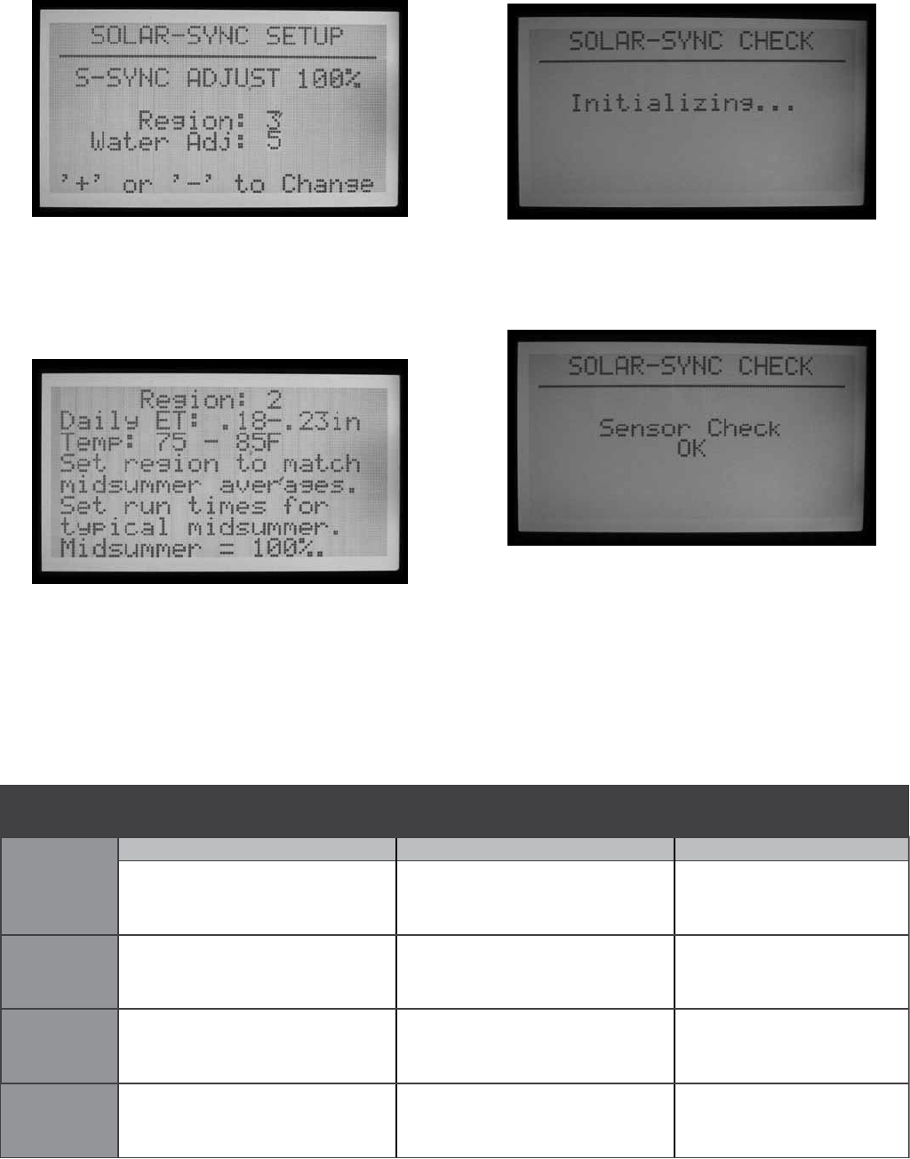
66
• The settings will be set to Region 3, Water Adj. 5.
Either of these factors can be changed, based on the
following explanations.
• Choose the Region that matches your location.
Regions are defined by average ET in summer months.
• At each Regional Setting, the blue Information button
on the ACC controller will also display help text for the
type of Region.
• The Water Adjustment factor is the ideal setting to
adjust watering for your specific landscape. This
setting can be from 1 to 10.
• If the Water Adjustment number is increased, the
system will water more. If the number is decreased, the
system will water less. This will allow you to find the
best balance between healthy plants and water savings.
SENSOR TEST
• When the sensor is installed, it is possible to test the
connection to the Solar-Sync sensor.
• Turn the dial to the Advanced Features dial position.
• Select ET Functions.
• U.S. Northern States
• Coastal Regions
If the average July ET is
< 0.17” (4.3 mm) per day
If the average temperature for July is
65°– 75°
(18°C – 24°C)
If the average temperature for July is
75° – 85°
(24°C – 29°C)
• Mountains
• U.S. Northern Inland States
If the average July ET is 0.18” – 0.23”
(4.6 mm – 5.8 mm) per day
• U.S. Southern States
• Inland/High Desert
If the average July ET is 0.24” – 0.29”
(6.1 mm – 7.4 mm) per day
If the average temperature for July is
85° – 95°
(29°C – 35°C)
• Deserts
If the average July ET is > 0.30”
(7.6 mm) per day
If the average temperature for July is
95° – 105°
(35°C – 41°C)
* For Southern hemisphere locations, use the month of January.
Region
1
Region
2
Region
3
Region
4
IF ANY OF THE CHOICES IN THE ROWS APPLY TO YOUR SITUATION, THEN THAT IS YOUR REGION SETTING CHOICE.
A B C

67
• Select Solar Sync Check. The screen will show
“Initializing…” for a few seconds as the controller
contacts the sensor.
• If the check is successful, the screen will show
“Sensor Check OK”. Continue with the Operation and
Adjustment procedures if necessary.
• If the check is not successful, the screen will show
“Sensor Check Failed”. Check sensor wiring and try
again. Remember, the wiring is DC polarized and the wire
from the green ET terminal in the ACC must be connected
to the green wire lead from the Solar-Sync sensor.
ASSIGN PROGRAMS
• Select which of the ACC programs are to be adjusted
by Solar Sync. You may specify which of the 6
automatic programs will be adjusted. All programs set
to Solar Sync will be adjusted by the same percentage,
as determined by the Solar Sync.
• Programs which are not adjusted will continue with
the same run times, and will not use the Solar Sync
adjustment. They may be adjusted manually, however.
This may be useful for specialized irrigation, or when
programs are used to control non-irrigation devices.
• Turn the ACC dial to the Set Station Run Times dial
position.
• Press the RIGHT arrow button to move through all the
run time fields, until the Seasonal Adjust selection is
highlighted.
•
Use the + and – buttons to change the Seasonal Adjust
to “S-SYNC”. This setting is between 100% and
101%, immediately after GLBL (global). When
Seasonal Adjust is set to S-SYNC, it will be adjusted
automatically according to the Solar Sync sensor.
• Use the Programs button to move through each of the
programs, and select S-SYNC for any program that
you want Solar Sync to adjust.
• Programs for which you do NOT want Solar-Sync
adjustment should be set to GLBL (they will stay at
the Seasonal Adjust level set manually for the rest of
the controller), or they may have individual Seasonal
Adjustments by Program as described in the Seasonal
Adjustment settings in basic controller operations.
• If the “S-SYNC” selection does not appear for a
program (between 100% and 101%), the Solar
Sync option has not been properly enabled for
the controller. Review the Preparation and Setup
procedures to troubleshoot.
SENSOR SHUTDOWN PROGRAMMING
The Solar-Sync sensor can be used for sensor shutdown
of watering at the controller. The Solar Sync can shut off
irrigation automatically for Rain, or for freezing conditions.
In the ACC controller, sensors are programmed to shut
down by individual program.
SENSOR MAPPING
• After the Solar-Sync sensor is set up and operational,
the built-in sensor inputs in the ACC controller can
be “mapped” to use the Solar Sync sensor instead of
other external sensors.

68
• Press and hold the Information button, while turning
the ACC dial to the Set Sensor Operation position.
Then, release the Information button.
• This will display the Sensor Configuration screen. This
is used to tell the ACC which of its 4 sensor inputs will
operate with the Solar Sync sensor.
• Choose the sensor input number with + or – buttons
while the Sensor number is highlighted.
• Then, press the down arrow button to move to
“Location”. Use the + or – buttons to select “SSync
Rain” or SSync Temp” to make that sensor input
respond to the Solar Sync sensor.
• When either or both Rain and Temp have been
assigned to Sensor numbers, turn the dial to another
dial position to save the setup.
SENSOR SHUTDOWN BY PROGRAM
• Turn the dial back to Set Sensor Operation (without
holding the Information button).
• The screen will display the sensor responses for
Program A (unless another program has been
selected). It will also display which sensors will shut
down Program A.
• If the Sensors (S1, 2, 3, and 4) are set to Off, they will
not shutdown the selected Program.
• Use the + or – buttons to change Off to Suspend, or
Pause. See the sensor section in the ACC manual
for a complete description of the difference between
Suspend and Pause.
• Suspend is generally the better choice for irrigation
programs! Make sure to fully understand Pause
before selecting this option.
• If Sensor 1 (S1) is assigned to SSync Rain, change the
response for S1 from Off to Suspend (with the + or –
buttons), to have the program stop watering when the
SSync Rain sensor is alarmed (active).
• If Sensor 2 (S2) is assigned to SSync Temp, change
the response for S2 from Off to Suspend (with the + or
– buttons), to have the program stop watering when
the SSync Temp nears freezing.
• Press the Programs button to move through each
program, and configure the shutdown responses for
the Solar Sync sensors, as desired.
OPERATION & ADJUSTMENT
• Turn the dial to the Run position. The S-Sync Adjust
status should appear in the display.
• When the system is newly installed, the S-Sync
Adjust is set to 100% on the first day (this cannot be
changed).
• At midnight, the S-Sync Adjust will change to 80% (or
greater) based on the sensor.
• The asterisk disappears from the Setup screen after a
full 24 hour period of sensor data. The asterisk is not
visible in the Run dial position display.

69
MAKING ADJUSTMENTS
After programming the Solar Sync module and your
controller, allow the system to operate for 3 days to gather
sun and temperature data.
• Observe the S-Sync Adjust value on the controller
display. If the amount seems to be lower or higher
than expected for the time of year, use the Water
Adjustment feature to correct.
• If necessary, the watering may be increased or
decreased with the Water Adjustment factor. Only
change the Region setting if you run out of adjustment
range within your selected region. The Region setting
adjusts sensitivity to weather change, and may have
unexpected results.
INCREASE OR DECREASE WATERING
• Turn the dial to the Advanced Features dial position.
• Select ET Functions.
• Select Solar Sync Setup.
• Use the down arrow to select the Water Adj. setting,
and use the + or – buttons to change the factor up or
down.
• Notice that as the Water Adjustment factor is changed,
the current S-Sync Adjust amount at the top of the
screen is changed. This can help you predict how
much more or less watering will occur, as a result of
the change (the actual minutes can also be seen at the
Set Station Run Times dial position, after adjustment).
• When adjustment is complete, return the dial to the
Run position.
CHECK RUN TIMES
After adjusting the Water Adjustment factor, you can turn
the dial to the Set Station Run Times to see the effects of
the change, in minutes (or gallons or liters, if flow has
been learned for the station).
• Select a station in an adjusted program. The screen
will show the “Programmed” run time, meaning
the original run time, and “Actual”. The Actual run
time is what will actually run with the effects of the
Solar-Sync adjustment.
• If the controller has learned flow by station, press and
hold the Information button, to view the estimated
water usage (in gallons or liters) after the effects of
the change.
• Run times occurring after midnight may be slightly
different, since the next adjustment for today’s ET will
occur at midnight.
NOTE: Set station run times for peak summer watering,
with seasonal adjust set at 100%
TRACKING THE ADJUSTMENT HISTORY (CONTROLLER
LOG)
• It is possible to review the adjustments the controller
has been making.
• Turn the dial to the Data History dial position.
• Use the arrow buttons to select the Controller Logs,
and press the + button.
• The Controller Log displays significant events at the
controller that are not alarms (alarms are tracked
separately, in the Alarm Log). Every change to
Seasonal Adjustment occurs approximately 2 seconds
before midnight, and each change is recorded in the
log.

70
• Use the – or + buttons to step backward and forward
through the Controller Log to track the S-Sync
changes. Each log will show the date and time, and the
Before and After settings for Seasonal Adjustment.
• If the controller has been operating unattended for
period of time, the performance of the Solar Sync
adjustments can be verified in this manner.
• If a user changes the Solar Sync setup (either Region
or Water Adjustment), this is also tracked in the
Controller Log. It will also show the Before and After
settings, but the log will show S-Sync Setup Changed
At Controller. This means it was changed by a human
operator.
• There may not be a Solar Sync log for each day! If the
weather conditions are stable and the Solar Sync does
not need to change, there will not be a log entry for the
day. The logs are only created when Solar Sync makes
a change to the Seasonal Adjustment settings.
• The Controller Log will store the most recent 250
controller events. The amount of other controller log
activity will determine how many days of Solar Sync
history are available.
SOLAR-SYNC SENSOR ALARMS
S-Sync RAIN ALARM, S-Sync TEMP ALARM
•
If the Solar-Sync sensors have been mapped to the
Sensor 1-4 inputs on the controller, and one of the
Solar-Sync sensors (Rain or Temp) detects an alarm
condition, the display will show : ATTENTION S-Sync
RAIN (or TEMP) ALARM
• This means that rain or near-freezing conditions
have suspended irrigation (as set in the Set Sensor
Operation dial position) until the alarm is cleared.

71
S-SYNC COMM FAILURE
• If the Solar-Sync sensor fails to respond to the ACC
controller, a Comm Failure message will be posted on
the display and a log will be entered in the controller
Alarm Log.
• This may indicate a problem with the wiring from the
controller to the Solar Sync sensor. Use the Sensor Check
function (Advanced Features dial position, ET Functions
menu) to check current status of the sensor.
• Alarm Log records are created whenever an Attention
message appears (Comm Fail and Restore, Rain and
Temp Alarms and Alarm Clears). They are also created
when an alarm condition is cleared. The Alarm Log
can be helpful in tracking the duration of rain or freeze
shutdowns, or communications failures with the
sensor.
• Turn the dial to the Data History position, and select
Alarm Log to view recent alarms. The most recent
alarm is always shown first. Press the – button to step
back through the alarm records, one at a time, up to
the most recent 250 alarm records. Each record with
have the date and time of the alarm event.

72
Imms-eT and The aCC ConTroller ............................................
IMMS-ET is central control software, designed to use
a central computer to track the deficits, and schedule
irrigation to replenish only the moisture that has been
lost. The goal is to reduce or eliminate excess watering
and grow healthier plants, without constant adjustment by
the operator.
ET= Evapo-transpiration. This is a technique for
determining how much moisture has been lost from the
soil reservoir for each station (often “zone”, or valve) of
irrigation, based on climatic data. Natural rainfall may
replenish some or all of this deficit. Automatic irrigation
will provide the balance of the moisture required to keep
plants healthy.
When ACC is in a computer central control system, it can
be used to report ET from a Hunter ET Sensor to the central
computer via IMMS control software. The computer can
use the ET information to create ET-based run times for
many controllers, including the original source controller.
• IMMS-ET requires a central computer and
communications to function.
The ET Sensor does not adjust the ACC controller directly
in standalone or offline use, even though you can see the
daily ET displayed.
The computer must perform a full sync for the ET
information to be retrieved, processed, and sent back to
the controller(s).
ET Requirements:
• Master Module (part 572000) version 4.0 or higher
(identified by green ET terminal, top left corner of
module, AND the presence of the “ET Ready!” sticker).
If the Master Module is an older version (with a red ET
terminal, or a green one without ET Ready displayed),
the ET functions will not be displayed until the module
is updated. The first production release version of the
ET Ready master module is version 4.22.010.
• ACC facepack version 4.0xx or higher.
• Hunter model ET Sensor. The sensor is connected
directly to the ET terminals, with two 18 AWG/1mm
direct burial wires, color-coded for polarity. Max
distance from sensor to controller is 100" (33 m), and
this distance should not be extended. Note that the
ET Module (from Hunter ET System) is not used, with
IMMS ET. The version number of the ET Sensor needs
to be 1,50.000.
ET SETUP AND OPERATIONS
Turn dial to Advanced Features dial position. If facepack
and master module are updated to versions 4 or later, the
ET Functions selection will appear in the menu selections.
ET FUNCTIONS
The ET functions listed in Advanced Features only apply
when an optional ET Sensor is connected.
After each ET function, it is possible to press the Back
button (controller left arrow key) to return to the ET
Functions menu and select another function.
While in the Advanced Features dial position, arrow down
to "ET FUNCTIONS" and press the + button. If ET has not
been enabled yet the screen will only give you the option
of selecting ET OPERATION.
ET OPERATION
Set to YES to enable ET operation. After turning the dial to
Advanced Features and selecting ET FUNCTIONS, press
the + button with ET OPERATION highlighted. The screen
will then ask you if you want to USE ET SENSOR. If you
have an ET Sensor and a central control IMMS system,
press the + button and set to YES to enable ET operation.
This will cause the controller display to begin showing
“Current ET: x.xx” in inches or millimeters, when the dial
is turned back to the Run dial position. Also, with ET

73
Operation enabled, and set to YES, more ET FUNCTION
options will be available and viewed in the ET FUNCTIONS
home screen.
NO will hide all ET functions and the daily ET will not
be read or displayed, and no ET will be available for the
central computer.
Other ET functions will not be available if ET Operation is
not set to YES. Enabling ET Operation is mandatory if you
choose to utilize the ET Sensors for irrigation shutdown. If
ET Operation is not programmed to YES, then the location
of ET Rain, ET Temp, and ET Wind will not be available
in the Extended Features of Set Sensor Operation, as a
selection in mapping sensor locations.
ET SENSOR CHECK
Turn the dial to Advanced Features and arrow down to ET
FUNCTIONS. Press the + button. Arrow down to ET
SENSOR CHECK, and press the + button to check the
sensor, after the ET Sensor is connected. The controller
will request an update from the sensor, and if a response
is received, will indicate OK.
If the test fails (ET Sensor
does not respond), check wiring to sensor, and try again.
Note ET sensor connection is polarized (green terminal on
the ACC master module must be connected to the green
terminal on the ET Sensor, black terminal must connect to
black terminal).
VIEW ET SENSORS
Displays current readings from all individual sensors on
the ET sensor platform. Turn the dial to Advanced Features
and arrow down to ET FUNCTIONS. Press the + button.
Arrow down to VIEW ET SENSORS, and press the + button.
The display will show current readings from all individual
sensors on the ET sensor platform.
ET, Rainfall, Wind speed, and Temperature will be
displayed according to the Units of Measure setting at the
Set Current Date/Time dial position.
Readings can be updated at any time, by performing a new
ET Sensor Check first.
Solar: always displayed in Watts/m2, based on hourly average.
Temp: air temperature taken near top of each hour, displayed in
Fahrenheit or Celcius.
Humidity: air humidity taken near top of each hour.
Wind: hourly average, in kilometers or miles per hour. If
optional ET Wind is installed this will show actual wind at the
location. Otherwise this value is set by the Automatic Prevailing
Wind factor setting on the underside of the ET Sensor.
Rain-New: Rainfall in inches or millimeters since the last time
the computer uploaded ET data.
Rain-1Hr: Rainfall in inches or millimeters within the last hour.
The controller checks the sensor every 15 minutes, and two
clicks of the rain gauge 0.02” (0.51 mm) within any 4 readings
will create a rain alarm (if the ET Rain is configured as a Sensor
input).
ET ALARM SETUP
Individual ET sensors can be used to perform alarm
shutdowns, by assigning them to the Sen 1-4 positions in
the controller. The ET Sensors will then function exactly
like “Clik” Sensor inputs. They may have Suspend or
Pause responses set by Program.
Assigning ACC Sensor 1-4 alarm functions to an ET
Sensor is done without connecting any additional wires.
The controller will use the sensor data as a virtual alarm.
For ET Alarm setup, you will need to assign or “map”
the ET sensors to the Sen 1-4 inputs, at the Set Sensor
Operation dial position “extended features”. The ET
Alarm setup function sets the shutdown levels for these
sensors, but they will not be effective until the mapping is
completed.
Press and hold the Information button, turn the dial to Set
Sensor Operation, and release the Information button.
Arrow down to Location selections. If ET is enabled,
there will be three possible selections to map to sensor
locations: ET Rain, ET Temp, and ET Wind. Select and
assign to specific sensor numbers as desired.

74
Turn the dial to another position, and then back to the
Set Sensor Operation dial position (without holding
Information). At this location, choose the Suspend or
Pause responses for each ET Sensor by program
ET Sensor shutdowns only apply to the controller to which
the ET Sensor is connected.
The ACC cannot shutdown other controllers as a result of
these alarms.
ET Sensor shutdowns are not instantaneous, and there
may be a delay of up to 18 minutes between an ET Sensor
alarm and the actual shutdown. If this is not acceptable, a
separate sensor (such as Rain-Clik or Freeze-Clik) should
be installed and wired directly to one of the Sen 1-4 inputs
for instant shutdowns.
The controller will automatically check the ET Sensor for
updated sensor readings every 15 minutes. If an ET sensor
causes a controller Pause or Suspend, that action will
remain in effect for at least 15 minutes until the controller
updates the readings. If the sensor returns to normal, the
Suspend or Pause settings will be cancelled, as with any
other sensor.
Shutdown Levels. Turn the dial to Advanced Features
and arrow down to ET Functions. Press the + button.
Arrow down to ET Alarm Setup, and press the + button.
The ET Alarm Setup function sets the shutdown levels
for the sensors that are mapped as a location for sensor
shutdowns.
Rain Max: The maximum amount of rain that will be
permitted before a program is shutdown for the rest of the
day. Move to this position with the arrow keys and use +/-
to set the maximum.
The ET Rain sensor will shutdown sensors after 0.02"
(0.51 mm) of rainfall within an hour (this amount is not
programmable), but the program may be permitted to run
again, if no more rain is detected. The ET Sensor checks
for rainfall every 15 minutes.
If the Rain Max amount is reached, the controller will no
longer attempt to run the program that day.
Temp: The air temperature can be used as a freeze sensor
to stop automatic programs, and the temperature at which
shutdown occurs is programmable (from 25° to 45°
Fahrenheit, -3.8° to 7.2° Celcius). Move to this position
with the arrow keys and use +/- to set the low temperature
shutdown.
Wind: If the optional ET Wind is installed, the wind speed
(in mph or kph) can be used to shut down designated
programs.
Reminder: Alarm settings are not in effect until the
Sensor 1-4 inputs have been assigned to them at the Set
Sensor Operation dial position, and responses have been
configured by program.

75
eVenT mode opTIons (aGC, surVeyor) ......................................
Event Mode is a special function of the controller designed
to work with Surveyor Golf control software.
Event mode allows the controller to run individual station
events which have been created for it by golf control
software. These events may not be created or edited in
the controller, and only special software can operate the
controller in this mode.
If you are not using Surveyor control software,
you should never use the Event Mode options.
The normal operating mode of the controller is called
FCP mode (“Field Controller Programs”). This means the
controller will use Programs A, B, C, D, E, and F normally.
If the controller is switched to Event mode, the A through F
Programs will not run.
Change to Event Mode: This will switch the controller to
the System Event mode (Surveyor Golf customers, only).
Turn the dial to Advanced Features. Press the + button.
Arrow down to Event Mode Options. Press the + button.
The first selection is Change to Event Mode.
The display will advise that this will run System Events
instead of programs A-F. If Event mode is selected, the
display will always show System Event Mode On when the
dial is in the Run position.
There is no special display when the controller is in the
normal FCP mode… as long as System Event Mode On is
not displayed at the Run position, the controller is in the
conventional FCP mode.
The Event Mode Options screen allows the user to view
three other selectable screens. While in the Event Mode
Options screen, simply highlight the desired selection and
press the + button. The three selections available are View
System Events, Event Count, and Delete Events. These
are only used in Surveyor Golf applications, to verify
downloaded schedule information.
View System Events: This will allow you to view System
Events for 1 to 3 days worth of downloaded System
Events.
The AGC/ACC controllers are always either in Event mode,
or FCP mode. The controllers can never be in both modes
at once.

76
First, select the Event Day you wish to view (1, 2, or 3).
Then press the right arrow button to view the downloaded
events for that day. Use the down arrow to scroll through a
large list of events.
Note: You cannot edit or change individual station events.
Event Count: This will show the total number of
downloaded events. It is useful for verifying that an entire
System Event download was received by the controller.
The event count totals should match the total number of
events in the Surveyor software.
Delete Events: This will permanently delete all downloaded
System Events. The controller will not be able to irrigate
until it has received a new System Event download, or until
it is switched back to the FCP mode and FCP programs are
created.
Types of Events: System Automatic Events are shown in
displays as “SAE”. They are the individual station starts
that have been scheduled by central software (Surveyor),
and downloaded to the controller.
SAEs are the primary operating mode of Surveyor’s
event-based irrigation scheduling. They may not be
created or edited at the controller. They are only created
when Surveyor applies flow processing to an event-type
system program at the computer, and downloads the
result to the controllers.
System Manual Events are displayed as “SME”. These
are manual starts sent to the controller by an operator at
the central computer. They are not part of the automatic
irrigation but are started by Surveyor software when the
controller is in Event Mode.
77
CenTral sofTWare and aCC-aGC CommunICaTIon modules ..
The ACC-COM-xxx module provides communications
for ACC/AGC series controllers. It can be used to
communicate with a remote computer via hardwire cable
(ACC-COM-HWR), dial-up telephone (ACC-COM-POTS)
or cellular phone (ACC-COM-GSM in North America, or –
GSM-E for international). This module may be installed in
wall mounted or pedestal mounted controllers.
THEORY OF OPERATION
The Com module is a communications manager. It will
contain the controller’s unique identification (address),
and enables communications into and out of the controller
when combined with other devices. The Com module also
coordinates communications between external devices
and the ACC controller facepack.
The Com module may also communicate with other
controllers, via optional RAD3 UHF radio modules (sold
separately) with antenna for wireless communications,
and/or an ACC-HWIM hardware interface module (sold
separately) for hardwired communications over Hunter
GCBL cable.
ACC-COM-POTS has dial-up communications ability
built-in, but may also require the additional modules for
outbound radio and/or hardwire connections with other
controllers.
ACC-COM-GSM (-E) has cellular communications built-in,
but requires a SIM card from the cellular provider, and
may also require the additional ACC-HWIM and/or RAD3
modules for outbound radio and/or hardwire connections
with other controllers.
Any Com module combined with a RAD3 radio installation
will respond to Maintenance Radio commands from a UHF
portable radio, equipped with a DTMF keypad.
Any Com module combined with a RAD3 radio installation
will respond to Maintenance Radio commands from a UHF
portable radio, equipped with a DTMF keypad.
ACC Com modules have no effect on ICR (or SRR) remote
control. The ICR and SRR remotes will work directly with
ACC, whether a Com module is installed, or not.
The ACC-COM-POTS enables dial-up telephone
communications via standard analog telephone line. It
can also enable either UHF radio communications, or
hardwired cable communications, or both. The hardwire
and radio options require other components to work.
Each communications option has different physical
requirements.
Dial-up Telephone: Plan ahead for routing a telephone line
into the controller. ACC-COM-POTS accepts a standard
4-wire RJ-11 telephone jack, but should be located within
6 ft./2m of the telephone outlet. Many trouble calls are
caused by exceeding the telephone wiring distance, and
routing telephone wires near electrically noisy equipment
(electric motors, fluorescent lighting, etc.). Dial-up
installations must be located as close to the telephone
connection as possible. All outdoor runs of telephone line
connections should be installed in metal conduit to reduce
interference.
Once an ACC controller is connected via telephone, it
can share the communications connection with other
controllers via radio and hardwire. The following
considerations apply to these optional outbound
connections.
UHF RADIO
The Communication Module ACC-COM-HWR,
ACC-COM-POTS, or the ACC-COM-GSM (E) does not
contain a radio. It is designed for use with a Hunter RAD3
UHF radio, which must be ordered separately.
The RAD3 radio will require an antenna, which is also sold
separately.
In steel enclosures, the antenna must be installed
externally (signals will not communicate from inside a
metal box).
• Plan ahead for mounting an external antenna. It will be
necessary to route the antenna cable from the radio
module inside the enclosure, to the antenna outside of
the enclosure. A site survey with comparable radios
is required before a final decision can be made about
antenna types and placement.
In the plastic pedestal enclosure, the Hunter IMMS ANT 2
antenna is designed to be mounted in the pedestal lid and
may be adequate for communications (to be determined in
advance by site survey).
In North America and most other countries, a license
is required before operating any radio transmission
equipment. Verify your local regulations and make
sure that you have obtained the proper licensing before
operating radio equipment.

78
HARDWIRED CABLE
The Communication Module ACC-COM-HWR,
ACC-COM-POTS, or the ACC-COM-GSM (E) does not
contain a hardwire connection terminal.
Any controller needing hardwired communications
must be equipped with an ACC-HWIM, in addition to the
ACC-COM-xxx communications module. The HWIM is
installed in the controller cabinet, on the ACC Master
Module (see ACC-HWIM instructions).
ACC-HWIM
terminal
Hardwired communications also requires Hunter GCBL
cable. This special cable uses 4 color-coded twisted
conductors, shielded with foil, and grounded with an
additional bare wire, in direct burial jacket. The cable is
also ordered separately.
• Plan ahead for routing the hardwired cable. The cable
must be routed from the ACC-HWIM terminal, out
of the enclosure, to any devices to which it will be
connected.
Turn the controller AC power OFF before installing the
Com module. You can turn off the AC power circuit to the
controller, or remove the fuse at the controller transformer
assembly. Pedestal mounted controllers have a power
switch, which can be pressed to the OFF position.
• Note that there are additional steps listed for
installation with RAD3 radio modules.
CommunICaTIon module InsTallaTIon for Wall mounT
ConTroller ................................................................................
1. Turn controller AC power off.
2. Open the facepack door frame and locate the
communications compartment cover on the back right
side of the frame. You may find it easier to complete the
following steps if the facepack door frame is completely
removed from the controller (disconnect facepack door
frame ribbon cable, open and lift up the door frame to
compress top hinge, and tilt out of lower frame).
3. Remove the communications compartment cover (6
screws).
4. Remove the ACC logo cover (two screws).
RADIO INSTALLATION, ADDITIONAL STEPS
If the Com module will be used with a RAD3 radio, the
radio ribbon cable should be connected now, before
installing the ACC-COM-xxx into its compartment.
Back of door, COM
and RAD3 installed
• The radio ribbon cable has a rectangular 14-pin
connector on one end for the Com module, and a DB-9
9-pin connector on the other end for connection to
the radio. The 14-pin connector only plugs one way,
and is keyed to assist proper orientation. Align the
connector and push into place on the top of the Com
module.
• When the Com module is installed in the opening,
make sure that the ribbon cable is visible on the back
of the unit, for connection to the RAD3 radio module.
5. If using the ACC-COM-POTS communications
module, route the RJ-11 compartment via the low
voltage conduit openings. Connect the telephone
cable to the mating receptacle on the bottom of the
ACC-COM-POTS modem, and insert until it clicks
positively into place.
RJ-11 connection
If using the ACC-COM-HWR or ACC-COM-GSM (E)
communications module, no additional steps or
connections need to be made. Continue on with the
following steps.
6. Route the radio antenna cable (if applicable) through
the recessed track next to the radio compartment, and
then through the low voltage conduit openings in the
cabinet, for connection to external antenna.
7. Leave sufficient slack in the telephone and antenna
cables to allow the door to open and close without
crimping.
79
CommunICaTIon module InsTallaTIon for plasTIC pedesTal
ConTroller ...............................................................................
(requires APPBRKT communications bracket, sold
separately)
1. Turn controller AC power off with the AC power switch
in the pedestal.
2. Open the facepack frame in the top of the pedestal, to
expose the communications module mounting area.
3. Install the APPBRKT communications bracket with its
supplied mounting hardware. This bracket is designed
to hold the Com module and a RAD3 radio module (if
radio is required).
4. Install the ACC-COM-xxx into the APPBRKT mounting
bracket. Secure the Com module with screws on each
of the 4 corners.
RADIO INSTALLATION, ADDITIONAL STEPS
• If radio communications will be used, connect the
RAD3 radio module cables to the Com module with its
ribbon cable and power connector first.
• Install the Com module into the bracket, and then
install the RAD3 on the APPBRKT with supplied
hardware.
• Install IMMS-ANT-2 in pedestal lid.
• Route antenna cable from the IMMS-ANT-2 through
the slot in the metal frame for the facepack, down into
the controller to the radio location.
• Connect the cable connector to the radio module
(be sure to turn the BNC connector until it locks into
place).
• Install the plastic cable guide (P-) with self tapping
screw as shown. Adjust cable before tightening to
insure that there is only enough slack to allow the lid
to open and close, without causing the cable to be
pinched.
5. Connect the ACC-COM-xxx ribbon cable extension to
the controller facepack connection on the underside
of the facepack frame. This is the keyed 14-pin
connector, top left, above the main facepack ribbon
connection.
6. When using the ACC-COM-POTS connect the RJ-11
telephone cable to the telephone service mating
receptacle. In high lightning environments, the
telephone cable may be connected through a grounded
surge suppression device (some computer power
strips have these built in).
7. Reapply controller power and verify that all devices
power up and have displays. Proceed to Setup and
Addressing of the Com module, in the next section.
8. Insert the ACC-COM module into the opening where the
logo cover was, with the display and buttons protruding
through the opening. Secure with 4 screws (supplied)
on each corner. The screws are recessed and a small
magnetic tip screwdriver is very helpful for this task.
9. Carefully insert the modular ribbon connector plug into
the mating receptacle in the door frame. This connector
is keyed and has slots which must be aligned correctly,
so that the connector can only fit one way. Press firmly
to make sure that the connector is fully seated.
RADIO CONNECTIONS, ADDITIONAL STEPS
• Before installing the RAD3 radio module, connect the
DB-9 connector from the ribbon cable to the top of the
RAD3 radio and secure with the connector screws (do
not overtighten).
• Connect the radio power cable from the RAD3 radio to
the radio power connection on the bottom of the Com
module.
• Connect the male BNC radio antenna connector to
the RAD3, before installing the radio into the radio
compartment.
• Install the radio into the radio compartment (see
RAD3 installation instructions for additional
information).
Reapply controller power and verify that the Com module
display lights up and displays characters.
If there is no display:
1. Double check ribbon cable connection from Com
module to facepack door frame receptacle.
2. Double check ribbon cable from facepack door frame
to controller cabinet.
80
When powered up, the Com module display will show the
version number, and will automatically check to see what
other communications devices are installed. This will take
a few seconds, and the display will show the type of COM
Module installed, ACC-COM-xxx when complete.
Note the version number and include it whenever seeking
technical assistance from Hunter Industries via phone or
email.
The Com module controls use the up and down arrow
buttons to make selections, a + and – button to change
individual settings, and an Enter key (far right), also
identified as the Backwards Arrow Button.
<
Set Controller ID: The controller ID, or address, is required
before any communications can take place. An address
may be any number between 1 and 999.
SET THE CONTROLLER ADDRESS
Press the Up arrow once. The display will show Controller
Address. The Address will be 0 if the module is new.
Press Enter to enter the Address edit mode. Blinking boxes
will appear over the controller Address number.
Use the + or – buttons to change the Address to the
desired setting. If you hold the + or – button for more than
a second, the numbers will change faster, in increments of
10. When you are close to the Address number you want to
set, release and press again to fine tune the address to the
precise number. You can go forward or backward with the
+ and – buttons to set the exact number.
Press the Enter button to enter the Address. The controller
will now be addressed.
The controller Address is assigned to a Com module,
not to the controller itself, nor to the ACC facepack. The
controller Address can be reprogrammed at any time
with the buttons, but it is important to remember that the
facepack of the ACC controller does not have an address
of its own. If you move an ACC facepack to another
controller, the address remains with the Com module
unless changed.
If you move a Com module with an Address number to
another controller without readdressing, it will receive
information meant for the first controller! The Addresses
cannot be changed remotely (from the computer) and can
only be set and changed at the Com module itself.
OTHER COM SETUP FUNCTIONS
ACC-COM-xxx detects other communications connections
and displays information about them. It also allows
operator control of some settings and functions.
Use the Up or Down arrow to navigate through main
topics.
“0” is the setting in a new, unadjusted Com module, which
can be changed after installation.
MASTER CONTROLLER
Shows YES if the controller has been designated as a
Master Controller or NO if the controller has not been
designated as a Master Controller. Press Enter to change,
+ or - to change, and Enter when done. The Master
Controller designation is reserved for the first controller
receiving communications with central for the Site.
Assigning a controller as a Master Controller or not as a
Master Controller will have no effect on communications.
It is reserved for future use.
CONTRAST
Default = 50. Adjusts display visibility for varying
conditions. Press Enter to adjust, + or – to change, and
press Enter when done. The display contrast may be
adjusted for daylight conditions where reflection makes
the display difficult to read.
RADIO TYPE
Shows a type of radio module, if one is found by the Com
module.
Radio communications can be used in 2 distinct ways:
• To connect a controller to additional controllers within
the same Site.
• To use a UHF Maintenance Radio (Hunter Model
TRNR) as a remote control for the controller.
LAST MR CMD (RADIO ONLY)
Displays the characters in the last-received UHF
Maintenance Radio command, for diagnostic purposes.
This setting is not shown if there is no radio. This setting
only applies to UHF Maintenance Radio and will not show
ICR remote commands.
DTMF WAIT (RADIO ONLY)
Sets amount of time allowed between characters in a
Maintenance Radio command, 1 – 5 seconds. The purpose
of this setting (default = 2 seconds) is to tell the Com
module how long to wait after hearing DTMF Maintenance
Radio commands, before assuming the command is
complete.
Maintenance Radio commands are sent from a UHF
portable radio by pressing buttons which send DTMF (Dual
Tone Multi-Frequency, also known as Touch-Tones) tones
to the Com module. When a command has been started,
the Com module assumes it is finished when the DTMF
seTup and addressInG The Com module .................................

81
wait period has elapsed or the radio carrier signal stops,
with no more tones.
A longer DTMF wait allows slower typing speeds of the
command on the radio. The trade-off is that the longer
wait means that it will take longer for the action to be
carried out (in other words, if the Wait is 5 seconds, it will
be 5 full seconds after the command has been sent before
the sprinkler turns on).
This setting is not shown if there is no radio. This setting
does not affect ICR remote commands.
MR DEFAULT RUN TIME (RADIO ONLY)
Default = 30 Minutes. This sets the automatic run time
for any station or SSG that is started by a Maintenance
Radio command, if no run time has been specified in
the On command. It is possible to turn a station or SSG
on without specifying a run time, and this setting will
automatically turn them off after the specified time if they
are not turned off by an Off comand. The Default Run Time
can be changed in 1 minute increments up to a maximum
of 60 minutes. This setting is not shown if there is no radio
and does not affect ICR remote commands.
MODEM TYPE
Indicates presence of a telephone modem in the Com
module. This display is informational and cannot be
changed from the Com module.
COUNTRY CODE
If a telephone modem is detected, the country code may
need to be changed to work with regional data modem
requirements. The default setting is “0” and for most
countries countries this is the correct selection.
If your country appears on the following list, change the
code display to the number shown:
Country Code
Australia 2
Czech Republic 3
Hong Kong 1
Hungary 1
India 1
Indonesia 1
Israel 1
Japan 4
North Korea 1
Malaysia 1
New Zealand 5
Philippines 1
Poland 1
Singapore 1
Slovenia 1
South Africa 6
Vietnam 1
To change the country code, press Enter and the code will
be highlighted. Use the + or – buttons to select the code,
and press Enter. The code will now be set.
HWIM
Indicates presence of a Hardwire Interface Module
(ACC-HWIM) installed in the controller. “None” indicates
no HWIM has been found, “Installed” indicates that the
HWIM is installed and has been detected. This display
is informational and cannot be changed from the Com
module.
ENTER DIAGNOSTICS
To use the built-in communications diagnostics, press the
Enter button at this display.
This will allow you to select from the following diagnostic
functions (use the up or down arrow buttons to move
through the choices).
Communications Status display [MOD RAD HW]
Pressing the left arrow button at any time will show a
status display for communications, showing transmit and
receive activity for each communications type. The display
shows: MOD RAD HW #, indicating Modem, Radio,
Hardwire, and number of data packets sent.
Under each item MOD, RAD, and HW, the letter T shows
transmit activity and R shows receiving data for that
communications component. The symbol * shows other
radio traffic (“carrier detect”).
82
This is a useful diagnostic tool.
MOD: Shows dial-up or cellular modem activity.
RAD: Shows T when the controller radio is transmitting,
and R when it is receiving data from another radio.
HW: Shows T when the controller is trans mitting over
GCBL cable, and R when receiving data via GCBL.
#: Shows the count of individual packets of data as they
are exchanged. This number continues to increase as
events are counted until it reaches 255, then begins
again at 1. Digital communications are divided into
packets of data, and sent in pieces called “packets”. After
each packet is sent, a confirming response is expected.
This counter tracks all communications in the module via
radio, hardwire, and modem.
The * may indicate other radio traffic (from other
sources). Communications problems that cannot be
explained by hardware issues are sometimes caused
by interference from other sources. If * is frequently
present when no ACC communications are taking place,
it may indicate that the frequency is very busy.
RADIO TONE TEST
If the controller does not have a RAD3 radio module
installed, the screen will show NONE for this diagnostic
function. Press the left arrow button twice to display the
Radio Tone Test, and press Enter to start the test. The
radio module will transmit a 5-second burst of data, to
confirm whether the radio is working. The burst can be
heard with another radio or scanner tuned to the same
frequency.
For this test to be effective, you will need a two-way radio
or scanner on the same frequency as the radio module.
• When the radio test is started, a burst of data
indicates a working radio module in the controller.
• If nothing is heard, either the radio is inoperative or
the wrong frequency has been selected for receiving.
• If a broken, rough-sounding, or very faint signal is
heard, there may be a problem in the antenna, antenna
cable, or connectors. This may also indicate
a problem in the radio module, although antenna/
cable/connectors. This may also indicate a problem
in the radio module, although antenna/cable/
connectors are more likely the cause. The easiest
way to check this is to swap the radio module with a
known good unit, connect to the same antenna and
cable, and repeat the test... if the sound cleans p, the
problem was the module. If the sound is still poor, it is
probably the antenna/cable/connector setup.
PING TEST
The ping test allows any controller to exchange
communications with another controller for test purposes.
Select a Target controller from the Source controller.
Enter the target address by pressing the + button while
the address number is blinking in the main Ping Test
screen. Press Enter when the address is correct, and the
Ping Test will begin. When the test is started, the Source
controller will “ping” the Target controller repeatedly and
show success or failure of the communications. Any other
controllers which can hear the test will also show the
results, while the test is taking place.
PING HUB
This test is used in Surveyor systems to ping test the
central interface (AGCHUB) instead of another controller.
SOFT RESET
This “reboots” the communications module if it is
temporarily confused. If the display or controls appear
to be locked up, soft reset will restart the module without
erasing data.
TOTAL RESET
This completely resets all data in the Com module. It
will erase any settings including the address! If the com
module is unresponsive and a soft reset does not solve
the problem, Total reset allows you to start over with a
clean installation. This is also useful when moving a Com
module from one installation to another, or when you are
uncertain what previous operators may have programmed
into the module.
OPERATING THE COM MODULE
With the Com module installed and operational, the two
most important steps are to verify that the controller
address is correct, and that the software is set up correctly
to connect to the Site.
The software documentation provides information on
configuring Sites and the connections for each Site. In
general, a com port must be assigned in the computer
for outbound communications, the Site must be created,
and a telephone number for the Site must be entered and
saved.
When the software has this information, any
communications for the Site will use the data to
automatically dial and connect to the Master controller
and anyh other controllers on the Site.

83
Problem Causes Solutions
No Display Check AC~ power to controller
Facepack is not firmly seated and locked,
and/or 9-pin connector is not fully
connected
Gray ribbon cable is not connected from
back of inner panel to cabinet
Fix power supply
Seat facepack in connector
Connect ribbon cable on back of facepack
door
Display reads “Attention” (may
be followed by Sensor number)
ATTENTION indicates an alarm, an
active sensor, or trouble in the system.
ATTENTION means turn the dial to Data
History, select the Alarm Log, and find
detailed messages about each individual
alarm with date and time. A complete list of
alarm messages is included after this table
Turn dial to Data History, select Alarm Logs,
and review for individual alarm events
The Controller Log and Station Log may
also be useful supporting information when
diagnosing problems
Station does not irrigate Field wiring or solenoid problem Perform Manual One- Station start and
observe display and output light
If light is red, check solenoid and field
wiring, including COM (common) wires.
Station outputs must not exceed 0.56A total
Controller does not irrigate
automatically
Possible programming errors
Sensor shutdown
Programmable Off in effect
Time/Date errors
Verify all programs Days to Water, Start
Times, and Station Run Times
Check display for Fault indication (if yes,
press + for status)
Check display for Off days
Verify controller time and date, including
AM/PM/24 hour settings
Rain or other Clik sensor does
not shut down system
Incorrect sensor type or connection
Incorrect sensor settings for Program
Use one normally-closed Clik-type sensor
per sensor port (SEN1-4). Verify that one
wire from each sensor is to + and one to –.
Do not connect multiple sensors to a single
port
Turn dial to Set Sensor Operation and verify
correct response for each program to the
sensor ( Pause or Suspend)
Controller does not recognize
output module (station size
shown incorrect)
Module seated incorrectly
Module slot skipped
Station output module overloaded
Verify that modules are seated all the way up
in wiring compartment, and module lock is On
Verify that no module slots have been
skipped, from left to right
Re-seat module, and observe green station
light flashing when module is recognized.
No station light or red light
Swap with known-good module, check for
green light. If new module works, replace
old module (probably surge overload). If
new known-good module also fails to light,
check gold and silver contacts for dirt,
corrosion, pests.
AC~ fuse blows Incorrect AC wiring
Surge on AC power line
Verify that AC connections are correct for
AC~ supply voltage
Check for lightning damage in vicinity
Multiple output module failures Lightning
Modules not installed correctly
Overcurrent message
Check and improve earth ground
Insure that modules are inserted correctly
with ground contact in back, and pushed
all the way up- red light should light
momentarily when module is recognized
Too much current for station output (0.56
Amp max). Divide solenoids over more
station outputs
TroubleshooTInG.......................................................................

84
The controller has 3 separate log files.
Each individual log has the date and time of the event at
the top of the screen.
Each type of log will show the most recent event first.
Use the + and – buttons to step through events, forward or
backward.
Alarm Log tracks all unusual events that require attention.
The Attention display (or “Fault”, in earlier versions) that
appears when the dial is in the Run position will almost
always have one or more corresponding Alarm Log
entries, with more detail. Turn the dial to Data History and
select Alarm Log whenever an ATTENTION display occurs.
Controller Log tracks general changes or occurrences for
the controller. Most of these are not alarm events.
Station Log tracks all station activity, including normal
and abnormal activity. It can be used simply to verify
whether irrigation occurred, or used as part of the
diagnostic process.
ALARM LOG MESSAGES
Sensor State Change Sensor changed state (Closed/
Open)
Missed Irrigation A station missed irrigating
Power Outage Controller or facepack power was
lost
Power Restore Controller or facepack power was
restored
ADM Fault A fault was reported by ADM
Pump Fault A pump decoder reported a fault
Station Fault A station decoder reported a fault
Pump Dec Failure A pump decoder failed
Sta Dec Failure A station decoder failed
Sensor Decoder A sensor decoder reported a fault
Alarm Log, Missed Irrigation “Mode” Labels
Mode appears when a station failed to complete irrigation
for some reason, and indicates why the station was
supposed be running in the first place.
Scheduled Station was running as part of an
automatic Field Controller Program (FCP)
(A, B, C, D, E, or F)
System
Event
Station was running as a System
Automatic Event
Manual Prg
All
Station was running as part of a Manual
All Stations Program
Custom
Manual
Station was running as part of a Custom
Manual Program
Manual
Station
Station was running as a Manual One
Station
SME Station was running as a System Manual
Event
MR
Program
Station was running as part of a
Manual All Stations program started by
Maintenance Radio
MR SSG Station was running as part of a SSG
started by MR
MR Station Station was running as a Manual One
Station started by MR
ICR
Program
Station was running as part of a Manual
All Stations program started by ICR
remote
ICR Station Station was running as a Manual One
Station started by ICR
ETS Progam Station was running as part of a Manual
All Stations started by ET System
ETS Station Station was running as a Manual One
Station started by ET System
Learn Event Station was running as part of the Learn
process
Test Event Station was running as part of the Test
program
aCC/aGC loG messaGes .............................................................

85
Alarm Log, “Reason” Labels
The Reason label indicates the type of alarm condition.
Unknown No reason specified
Overflow Overflow alarm occurred
Underflow Underflow alarm occurred
Overcurrent Station Overloaded
Activated Sensor Activated
Deactivated Sensor Deactivated
Damaged Decoder is damaged (continuous low
voltage output)
Comm Fail Decoder communications failure - no
response
Unavailable Cannot run station due to too many
stations already running
Comm Restore Communications was restored to a
decoder
Config Fail Failure occurred when attempting to
configure a sensor decoder on the
2-wire path
Flow Totals Failure occurred when attempting
to get the flow totals from a sensor
decoder
Flow Detail Failure occurred when attempting to
get the flow detail data from a sensor
decoder
Sensor Alarm The status of the Sensor Decoder
Alarm Polling has changed
Lith Fail The lithium battery in the facepack
has failed
Clock Fail A problem exists with the Real Time
Clock (RTC) in the facepack
CONTROLLER LOGS
Track significant events at the controller, which are not
necessarily alarms or malfunctions.
Message Description
EASY RETRIEVE
RESTORED
Easy retrieve programs
were restored
PROGRAM X RESET BY
CENTRAL
Field controller Program X
was reset by central
OFF MODE SET AT
CONTROLLER
Dial was put in OFF
position
RUN MODE SET AT
CONTROLLER
Dial was taken out of OFF
position
PROGRAMMABLE OFF SET
AT CONTROLLER
Programmable Off was
initiated at the controller
PAUSE MODE SET AT
CONTROLLER
Pause Mode was initiated
at the controller
PAUSE MODE CANCELLED
AT CONTROLLER
Pause Mode was cancelled
at the controller
PROGAMMABLE OFF SET
BY CENTRAL
Programmable Off was
initiated by central
PAUSE MODE SET BY
CENTRAL
Pause Mode was initiated
by central
PAUSE MODE CANCELLED
BY CENTRAL
Pause Mode was cancelled
by central
SUSPEND MODE SET BY
CENTRAL
Suspend Mode was
initiated by central
SUSPEND MODE
CANCELLED BY CENTRAL
Suspend Mode was
cancelled by central
PROGRAMMABLE OFF
TIMEOUT
Programmable Off timed
out
PAUSE TIMEOUT Pause timed out
NO WATER WINDOW
VIOLATION
A No Water Window
Violation occurred
MEMORY CORRUPTED
RESET TO DEFAULTS
Memory is suspect and
was reset to defaults by
microcontroller
ALL DATA RESET TO
DEFAULTS
All data was reset in the
controller
ALL LOGS RESET AT
CONTROLLER
All logs were reset at the
controller
FLOW TOTALS RESET AT
CONTROLLER
All flow totals were reset at
the controller
ALL PROGRAM DATA
RESET AT CONTROLLER
All programs were reset at
the controller
ALL NAMES RESET AT
CONTROLLER
All names were reset at the
controller
IRRIGATION STOPPED BY
CENTRAL
Irrigation was stopped by
the central

86
Message Description
IRRIGATION STOPPED BY
MAINT RADIO
Irrigation was stopped by
maintenance radio
PAUSE MODE SET BY
MAINT RADIO
Pause Mode set by
Maintenance Radio
PAUSE MODE CANCELLED
BY MAINT RADIO
Pause Mode cancelled by
Maintenance Radio
FCP MODE SET AT
CONTROLLER
FCP Mode set at controller
EVENT MODE SET AT
CONTROLLER
Event Mode set at
controller
FCP MODE SET BY
CENTRAL
FCP Mode set by central
EVENT MODE SET BY
CENTRAL
Event Mode set by central
PROG OFF CANCELLED AT
CONTROLLER
Programmable Off was
cancelled at controller
CUST MAN PROGRAM X
RESET BY CENTRAL
Custom Manual Program X
was reset by the central
ALL FCPs RESET BY
CENTRAL
All Field Controller
Programs (A to F) were
reset by central
ALL CUST PROGRAMS
RESET BY CENTRAL
All Customer Manual
Programs (1 to 4) were
reset by central
ALL STATION DATA RESET
BY CENTRAL
All station related data was
reset by central
ALL SSG DATA RESET BY
CENTRAL
All SSG related data was
reset by central
ALL P/MV DATA RESET BY
CENTRAL
All Pump/Master Valve
data was reset by central
ALL SENSOR DATA RESET
BY CENTRAL
All Sensor 1 to 4 data was
reset by central
ALL FLOW SENSOR DATA
RESET BY CENTRAL
All Flow Sensor data was
reset by central
FLOW ACCUMULATORS
RESET BY CENTRAL
All Flow Accumulators
were reset by central
FLOW TOTALS RESET BY
CENTRAL
All Flow Totals were reset
by central
TIME OR DATE CHANGED
AT CONTROLLER
The time and/or date was
changed at the controller
TIME OR DATE CHANGED
BY CENTRAL
The time and/or date was
changed by the central
STATION LOGS
Station Log records all station activity in the controller.
The Mode labels are the same as shown in the Run dial
position, when stations are running.
Mode Meaning
AUTO Automatic Field Controller Program (FCP)
AUTOEV Automatic System Event
MAN Manual Station/Program
CUST Custom Manual Program
MAN-EV Manual System Event
MRP Maintenance Radio Program
MRS Maintenance Radio Station
ICR ICR Program/Station
ETS ET System Program/Station
LEARN Learn Mode
TEST Test Program
PAUSE Paused Program/Station
SUSP Suspended Program/Station
The Status portion shows the type of event, or the reason
a station did not complete. Each start and stop of a station
is recorded. If a station has a “Pause” or “Delayed” event,
it does not necessarily indicate a malfunction. There are
several causes that may occur during normal irrigation.
Status Description
System Pause Pause issued by controller or central
System Susp Suspend issued by central
Sensor Pause Pause initiated from sensor activation
Sensor Susp Suspend initiated from sensor
activation
No Water Win Station ran into no water window
Complete Station completed run time
Delayed Soak completed
Interrupted Indicates that a station was
interrupted by pause/suspend
Max Sta Run Station could not run since max
stations were already running
Overcurrent Station shut down due to overcurrent
Stopped Station was stopped due to dial put in
Off, Stop Irrigation command received
or higher priority event
Man Sta Chg Station stopped due to manual station
advance
Flow Pause Irrigation was delayed due to flow
isolation process
ADM Flt Susp Irrigation was suspended due to an
ADM fault
Dec Com Fail Irrigation was stopped due to a comm
failure with decoder
87
speCIfICaTIons ...........................................................................
DIMENSIONS
ACC1200,ACC99D Cabinet :
12⅜" H x 15" W x 6
716
" D
(31.37 cm H x 39.37 cm W x 16.38 cm D)
ACCPED Metal Pedestal:
36⅛" H x 15" W x 5" D
(91.45 cm H x 39.37 cm W x 12.7 cm D)
ACC1200PP, ACC99D-PP Plastic Pedestal:
38⅜" H x 21
916
" W x 15⅞" D
(97.47 cm H x 54.61 cm W x 40.32 cm D)
ELECTRICAL
Transformer Input
Supply wires must be 14 AWG (1.85 mm) or larger!
120/230 VAC
50/60 Hz
1.2 A max at 120V/0.73 A max at 230V
Transformer output
24 VAC, 4A, @ 120 VAC
Station output: 0.56 A @ 24 VAC
Pump/Master Valve output: 325 mA @24 VAC
24 VAC Test terminal output: 420 mA @ 24 VAC
Solenoid capacity: 2 standard 24 VAC Hunter solenoids per output (0.56 Amps max), 14 solenoids max simultaneous
(includes dual P/MV outputs).
Battery, facepack: 9 VDC alkaline, for facepack remote power only.
Battery, facepack, internal: CR2032 lithium for real time clock only.
Cleaning
Clean only with cloth dampened with mild soapy water.
FEATURES & GENERAL SPECIFICATIONS
• 6 Automatic Programs
• 10 Start Times per program
• Station Run Times, 1 second to 6 hours in Conventional Controllers, and 15 seconds to 6 hours in Decoder Controllers
• Delay between Stations, 1 second to 9 hours, 59 minutes
• Interval Day scheduling, 1 to 31 days
• 4 Custom Manual programs (for manual or remote start only)
• 20 Simultaneous Station Groups with up to 4 stations each
• 2 normally closed Pump/Master Valve outputs, configured by station
• 1 Flow Meter, with Station level learning and diagnostics
• 4 Hunter “Clik” sensor inputs, with programmable shutdown by program
• Test Program run times: Conventional, 1 second to 15 minutes each, Decoder, 15 seconds to 15 minutes each
• Up to 42 stations, conventional
• Up to 99 stations, decoder

88
parTs ..........................................................................................
Item Description Catalog No.
Com module for
dial-up (POTS)
ACC-COM-POTS
Com module for GSM
cell (USA)
ACC-COM-GSM
Com module for GSM,
International
ACC-COM-GSM-E
Com module for radio
and hardwire only
ACC-COM-HWR
Hardwire Interface
Module
ACC-HWIM
UHF radio
(No antenna)
RAD3
Antenna Isolation
Module
AIM-BNC
Item Description Catalog No.
Front Faceplate
Face Pack
571500
Front Face Pack
Door Frame
589000
Metal Front Door
w/o Lock
585500
Lock & Key Set
(Not Shown)
387300
Key Set (2)
(Not shown)
122516
Metal Cabinet
w/o Door
585000
Inner Controller only
(With 585100),
no modules or
transformer
586005
Door Ribbon Cable
(Wall mount only)
585100
Transformer Assembly 587000
Master Module 572000
Small Hole Plug 654400
Large Hole Plug 654500
Station Module(s)
ACM-Module
(Standard)
AGM-Module
(Extreme service)
ACM600
AGM600
SmartPort
®
Assembly
including Nut
112200
Decoder Output Module
ADM99
1
2
4
3
5
6
7
8
9
10
11
12
13
14
15
COMMUNICATION MODULES AND PARTS
16
16
16
16
17
18
19
3
1
2
8
5
14
10
9
11
12
7
6
4
17
16
18
19
9
1315
WALL MOUNT CONTROLLERS (ACC1200, ACC99D)

89
Item Description Catalog No.
Front Faceplate
Face Pack (ACC)
571500
Front Face Pack (AGC) 571505
Front Face Pack
Door only
620000
Plastic Ped Com and Radio
Bracket, including Ribbon Cable
APPBRKT
Frame Adapter 145500
Lid including Lock 553305
Lid Antenna for Ped,
UHF
IMMSANT2
Lid Hinge Pin 558400
SmartPort
®
Bracket 576000
SmartPort
®
Wiring
Harness
112210
Master Module 572000
Decoder Output
Module
ADM99
Transformer Assembly 587000
J Box 145410
Pedestal Door with
Screen
553205
Lock & Key Set
(Not shown)
558000
Key Set (2)
(Not shown)
122516
ACC Ped Inner Panel
Cabinet with
Transformer
621230
Ribbon, Inner
Controller to
Facepack Door
585105
Mounting Template
Kit, includes
Template #558600, and Hardware
#420200
581700
Ribbon, Extension for
Com Modules in
Pedestals
619900
Station Module(s)
ACM-Module
(Standard)
AGM-Module
(Extreme Service)
ACM600
AGM600
1
2
3
4
5
6
7
8
9
10
11
12
13
14
15
16
17
18
19
20
1
2
3
20
4
14
8
19
11
9
13
12
10
14
18
5
7
6
PEDESTAL CONTROLLERS (ACC1200PP, AGC1200PP, ACC99DPP, AGC99DPP)
ACC/AGC CENTRAL SYSTEM COMPONENTS
(ACC1200, ACC99D, ACC1200PP, AGC1200PP, ACC99DPP, AGC99DPP)
Hardwire/Radio Communication Module ACC-COM-HWR
Telephone Communication Module ACC-COM-POTS
Cellular Communication Module ACC-COM-GSM
Cellular Communication Module outside US ACC-COM-GSM-E
Radio Communication Module RAD3
Hardwire Interface Module ACC-HWIM
ET Sensor for IMMS ET ETSENSOR
1
2
3
4
5
6
7
90
A
Address 16, 57, 59, 61, 62, 77, 80, 82
Adjustment 22, 64, 67, 69, 72
ADM 19, 24, 25, 34, 41, 42, 46, 47, 57, 59, 60, 63, 84,
86
Alarm 14, 27, 28, 29, 31, 32, 33, 34, 35, 38, 39, 41, 42,
56, 62, 63, 70, 71, 73, 74, 84, 85
Antenna 18, 77, 78, 79, 82, 88
Attention 29, 32, 42, 44, 70, 84
C
Cable 1, 4, 17, 77, 78, 79, 82
CCC 18
Clik 13, 15, 33, 35, 60, 61, 73, 74, 87
Comm 86
Comm failure 86
Communications 2, 10, 13, 17, 18, 39, 64, 71, 72,
77, 78, 80, 81, 82, 85
Communications manager 77
Com port 82
Controller log 39, 69, 70, 84
CSD 17, 18
Custom 54
Custom manual 19, 33, 50, 53, 84, 86, 87
Cycle 24, 44, 50, 54
Cycle and soak 24, 50, 54
D
Daily 38
Data history 38
Date/time 18, 73
Daylight saving 17, 20
Day schedules 56
Days to water 18, 22, 52
Decoder 12, 16, 19, 24, 25, 30, 33, 40, 41, 46, 47, 51,
56, 59, 61, 63, 84, 85, 86, 87
Deficit 72
Delay 28, 29, 35, 45, 50, 74
Dial 1, 2, 11, 13, 17, 19, 20, 21, 22, 24, 25, 26, 27, 28,
29, 32, 33, 34, 35, 36, 37, 38, 39, 40, 42, 44, 45, 46, 47,
48, 50, 51, 52, 53, 54, 55, 57, 58, 59, 60, 62, 63, 64, 65,
66, 67, 68, 69, 70, 71, 72, 73, 75, 77, 82, 84, 86, 88
Dial tone 17
Download 40, 59, 76
E
Earth 5, 8
Easy retrieve 85
ET 72
ET sensor 13, 30, 34, 35, 41, 64, 65, 72, 73, 74, 89
Evapo-transpiration 64
Event 86
Event mode 86
F
Facepack 2, 64, 89
Fault 11, 19, 84, 86
Firmware 26, 35, 40, 64
Flow 15, 19, 25, 26, 27, 28, 29, 30, 33, 38, 46, 47, 56,
60, 85, 86, 87
Freeze 15, 30, 35, 61, 74
Frequency 80
G
Gallons 26, 38, 69
GCBL 17, 77, 78, 82
GLBL 22, 67
Global 22
Golf 75
Ground 5, 10
GSM 17, 18, 77, 78, 88, 89
H
Hardwire 13, 81, 88, 89
I
ICR 3, 16, 50, 54, 77, 80, 84, 86
Inrush 58
Installation 2, 4, 6, 11, 25, 46, 48, 56, 63, 65, 77, 78,
79, 80, 82
Interval 18, 23, 87
L
Learn 25, 27, 28
Lights 2, 57
Limit 19, 26, 28, 29, 30, 43
Line 17, 37, 41, 48, 49, 56, 63, 77
IndeX ..........................................................................................
91
Liters 26, 38, 69
Log 18, 29, 32, 38, 39, 41, 42, 44, 69, 71, 84, 85, 86
M
Manual 14, 15, 17, 31, 36, 39, 41, 47, 48, 50, 54, 68,
76, 86, 87
Master module 25, 34, 46, 64, 65, 72, 73
Metric 20, 46
Millimeters 72, 73
Modem 1, 78, 81, 82
N
Non-water window 44
Normally closed 13, 14, 24, 30, 31, 34, 45, 87
Normally Closed 24, 32, 45, 46, 59
Not learned 26, 28
Not monitored 26, 27, 28
O
OFF 8, 17, 19, 21, 30, 32, 39, 54, 55, 56, 63, 78, 85, 86
Output 3, 10, 12, 13, 14, 16, 19, 25, 33, 40, 41, 42, 46,
47, 51, 56, 57, 58, 59, 60, 61, 63, 85, 87
Overcurrent 39, 41, 42, 85, 86
Overflow 29, 39, 42, 85
Overlap 17, 20, 21, 36, 37
Overload 63
P
Parts 88
Path 12
Pause 2, 29, 31, 32, 33, 35, 42, 62, 68, 73, 74, 85, 86
Pedestal 6, 7, 16, 17, 77, 79
Percentage 22, 43, 67
P/MV 23, 24, 42, 45, 54, 59, 86, 87
POTS 17, 77, 78, 79, 88, 89
Power 3, 5, 6, 7, 8, 11, 13, 14, 15, 18, 43, 56, 57, 58,
65, 78, 79, 84, 87
Power factor 58
Program 18, 19, 20, 21, 22, 23, 24, 27, 30, 31, 32, 33,
35, 36, 37, 38, 40, 44, 45, 47, 48, 49, 50, 51, 52, 53, 54,
57, 58, 59, 61, 62, 64, 67, 68, 73, 84, 85, 86, 87
Pump 3, 13, 14, 18, 23, 24, 30, 42, 46, 58, 59, 63, 84,
86, 87
Pump/master valve 3, 13, 18, 46, 59, 86, 87
R
Radio 1, 17, 18, 77, 78, 79, 80, 81, 82, 86, 88
Rain 14, 15, 30, 31, 34, 35, 55, 67, 68, 70, 71, 73, 74
Rainfall 35, 72, 74
Rain off 55
Receive 19, 30, 57, 60, 63, 65, 80, 81
Region 69
Relay 14, 31, 42
Remote control 16, 48, 77, 80
Replace 5, 6, 28, 39, 49, 52, 64
Report 29, 43, 59, 72
Restore 52
Retrieve 39, 52, 56
Ribbon 4, 78, 79
Run off 24
Run times 22, 27, 50, 51, 52, 54, 56, 64, 67, 69, 72, 87
S
Save 37, 38, 44, 45, 47, 48, 50, 52, 68
Scheduling 76, 87
Seasonal adjust 21, 22, 44, 64, 67
Sensor decoder 19, 25, 30, 33, 41, 47, 59, 60, 61, 62,
63, 84, 85
Sensors 1, 13, 14, 15, 16, 19, 25, 30, 31, 33, 34, 35,
46, 59, 60, 61, 67, 68, 70, 73, 74
Shutdown 1, 14, 17, 30, 32, 35, 67, 68, 73, 74, 87
Site 18, 37, 64, 77
Smartstack 37, 48
Soak 24, 44, 50, 54, 86
Solar 64, 65
Solar-sync 64, 65, 66, 67, 68, 69, 70, 71
Solenoid 12, 14, 41, 57, 58
Specifications 87
Sprinkler 4, 21, 31, 37, 81
SSG 17, 19, 36, 37, 38, 47, 48, 49, 50, 51, 53, 54, 81,
84, 86
SSG/smartstack 37, 48
Stack 20, 21, 36, 53
Stacking 17, 20
Start time 20, 23, 30, 36, 44, 53
Station A, 3, 5, 6, 11, 18, 19, 21, 22, 24, 27, 33, 37, 38,
39, 40, 44, 45, 47, 48, 50, 51, 53, 54, 58, 59, 63, 67, 69,
84, 85, 86, 87, 88, 89
Status 3, 11, 12, 26, 32, 40, 56, 57, 81, 86
92
Stop 13, 16, 17, 30, 31, 35, 39, 42, 51, 53, 54, 68, 74,
86
Summary 19, 21, 22, 24
Suspend 30, 31, 32, 85
Sync 72
System 16, 17, 18, 33, 54, 72, 75, 76, 84, 86, 89
T
Technical support 40
Telephone 1, 17, 18, 37, 77, 78, 79, 81, 82
Temperature 30, 35, 40, 64, 69, 73, 74
Test 2, 14, 19, 33, 51, 52, 66, 82, 84, 86, 87
Toggle 23
Totals 38, 42, 76, 85
Transformer 42
Transmit 81, 82
Troubleshoot 67
U
UHF 17, 18, 77, 80, 88, 89
Underflow 29, 30, 39, 43, 85
Update 13, 40, 64, 73
V
Version 13, 26, 30, 39, 40, 44, 64, 72, 80
W
Wind 30, 35, 73, 74
Window 21, 36, 44, 47, 86
Wire 3, 5, 6, 8, 10, 12, 13, 14, 15, 16, 17, 24, 25, 33,
41, 42, 46, 47, 56, 57, 59, 60, 61, 62, 63, 67, 77, 78, 85
Wiring 3, 5, 6, 8, 10, 11, 12, 13, 15, 41, 56, 67, 71, 73,
77
Z
Zone 30, 72
Hunter Industries Incorporated • The Irrigation Innovators © 2010 Hunter Industries Incorporated
1940 Diamond Street • San Marcos, California 92078
www.hunterindustries.com
LIT-389 E 01/10
