Advanced Troubleshooting Guide
for
EasyStart
TM
Soft-Starters

EasyStart Advanced Troubleshooting Guide
1
©2022 Micro-Air Corp April 20, 2022, revision 2.0
Table Of Contents
WARNING ..................................................................................................................................................... 2
Introduction .................................................................................................................................................. 2
Getting Started – How to Use This Document .............................................................................................. 2
Problem Characterization ............................................................................................................................. 2
Section 1 – Compressor Problems Without EasyStart .................................................................................. 4
Section 2 – Wiring Installation Resources ..................................................................................................... 5
Application Specific Resources ................................................................................................................. 5
Generic Wiring and Procedure.................................................................................................................. 5
Section 3 – The Compressor Has Never Started on Utility Power .............................................................. 13
Section 4 – The Compressor Starts on Utility Power but Not Satisfactorily ............................................... 16
Section 5 – The Compressor Has Never Started on Limited Power ............................................................ 20
Appendix A: Additional Resources .............................................................................................................. 30

EasyStart Advanced Troubleshooting Guide
2
©2022 Micro-Air Corp April 20, 2022, revision 2.0
WARNING
Some of the testing in this document involves being near or interfacing with live AC utility power. This
power can cause serious or fatal injury if mis-handled. The recommendations contained herein should
only be performed by qualified and trained service persons. Please contact Micro-Air for more assistance
using our Micro-Air Contact Us Page.
Introduction
EasyStart soft-starters are designed for excellent reliability and durability. Every EasyStart we produce is
tested many times throughout the build process, and finally on a live compressor before it leaves Micro-
Air to ensure it will work in the field. This document is provided for in-depth technical investigation to
resolve installation and operational issues and to help determine if EasyStart is the cause of the problem.
Getting Started – How to Use This Document
There are a few steps that create a workflow for the successful installation and operation of EasyStart.
The most effective troubleshooting steps can be taken when we first characterize the problem and
determine what specifically is working and what is not. This means we must determine where you are in
the workflow.
1. Use the chart in the Problem Characterization section to know where you are in the workflow
2. Proceed to the troubleshooting section pointed to by the Problem Characterization section
3. Follow the recommendations in the troubleshooting section
a. Determine it is the right section for you by answering the initial questions
b. Ensure you understand normal operation using the relevant appendix information
c. Perform the recommendations to determine the cause and resolution
4. Use the Micro-Air Contact Us Page if you have further trouble. Include detailed information:
a. The problem you are experiencing
b. How you have used this document
c. The steps you have taken to find a resolution
Problem Characterization
Use this section to determine where you are in a typical workflow and characterize what is not working.
Navigate Figure 1 to determine where you are in this workflow. Start at the top and work your way down.
Each level points to a relevant troubleshooting section to go to next. Move down along the green arrows
if the section is not for you, or out along the red arrow if your problem matches the description and
proceed to the indicated troubleshooting section.

EasyStart Advanced Troubleshooting Guide
3
©2022 Micro-Air Corp April 20, 2022, revision 2.0
Section 1
Section 2
Section 3
Section 4
Section 5
Section 6
Figure 1

EasyStart Advanced Troubleshooting Guide
4
©2022 Micro-Air Corp April 20, 2022, revision 2.0
Section 1 – Compressor Problems Without EasyStart
EasyStart is meant to be added into systems that are otherwise functioning normally. EasyStart can be
added into these systems and could help in ways beyond its primary design, however it cannot be
expected to resolve issues it was not designed to resolve.
For example, a compressor will shake on start-up as the motor quickly comes up to speed. EasyStart
slows this process down, potentially reducing the initial vibration and so less mechanical stress may be
as a result.
Keep and finish? Delete? 2DO

EasyStart Advanced Troubleshooting Guide
5
©2022 Micro-Air Corp April 20, 2022, revision 2.0
Section 2 – Wiring Installation Resources
All EasyStart installations are electrically identical, regardless of what A/C make, model, manufacturer, or
application you have. This section will take a comprehensive look at each EasyStart connection to help
find what may be missed during installation. Please take the time to consider a fresh look at what you
have already checked.
Application Specific Resources
Our EasyStart Knowledge Bank is where we have all of our EasyStart resources. Navigate to the installation
section of the knowledge bank and check for a specific installation guide or schematic for your system.
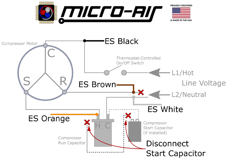
Generic Wiring and Procedure
As previously stated, all installations are electrically identical. However, how and where these connections
are made will vary across applications. Figure 2 shows a typical compressor schematic without EasyStart.
Note: Figure 2 is an electrical schematic representation. Your system will be electrically identical but
this is not a wiring diagram. How connections are exactly wired is application specific.
Note: L1 and L2 may be reversed in your application and is not important for EasyStart.
The first thing to do is identify the three compressor wires “C”, “S”, and “R”, and the compressor run
capacitor in your application. These two components will be in every application. EasyStart can be
installed in any system when these components are identified. Figure 3 shows a typical compressor
schematic that has EasyStart installed, overlayed over Figure 2.
Figure 2 - Generic Factory Compressor Wiring
EasyStart Advanced Troubleshooting Guide
6
©2022 Micro-Air Corp April 20, 2022, revision 2.0
Figure 3 - Generic Compressor Wiring with EasyStart Installed
Note: Figure 3 is an electrical schematic representation. Your system will be electrically identical but
this is not a wiring diagram. How connections are exactly wired is application specific.
Every installation is electrically correct when installed as shown in Figure 3. We will reference L1 and L2
as depicted, however they may be reversed in your application and is fine. Making your connections in
reference to the identified compressor motor wires and run capacitor wires will ensure proper installation.
Wiring Criteria
The 5 criteria below ensure that EasyStart is wired correctly in any system, shown graphically by Figure 3.
• EasyStart Orange is connected to the Compressor “S” wire
• EasyStart Black is connected to the Compressor “C” wire with no hardware in-between
• The Compressor “R” wire is disconnected from L2 and connected exclusively with EasyStart Brown
• EasyStart White is connected to L2/Neutral, where the Compressor “R” wire used to land
• Any start devices are defeated by removing the wire between it and the “H” run capacitor terminal
Table 1 in section Wiring Criteria Checklist is a checklist to ensure that the above wiring criteria is met.
Use it and the accompanied descriptions to ensure EasyStart is wired correctly in your application.

EasyStart Advanced Troubleshooting Guide
7
©2022 Micro-Air Corp April 20, 2022, revision 2.0
Wiring Criteria Checklist
This section provides a step-by-step procedure to verify the wiring of EasyStart as outlined in the Wiring
Criteria section. Use the Table 1 checklist and its detailed descriptions to verify the wiring criteria is met.
This section does not consider EasyStart mounting or routing its wires where needed.
WARNING: Some of the testing in this document involves being near or interfacing with live AC utility
power. This power can cause serious or fatal injury if mis-handled. The recommendations contained
herein should only be performed by qualified and trained service persons. Please contact Micro-Air for
more assistance using our Micro-Air Contact Us Page.
Table 1 - EasyStart Wiring Checklist
Order
Verification Step
✓
1.
Remove and disconnect all AC power from the system
2.
Locate the A/C unit and gain access to the enclosure
3.
Identify the compressor motor
4.
Locate the wire cover on this motor where the C, S, and R wires exit.
Look for identifying markings of these wires near, on, or under this
cover on the motor exterior.
‘C’ color
‘S’ Color
‘R’ Color
5.
Trace each of the three compressor wires out and inspect where they land
6.
The compressor “S” wire will land on a terminal connected to the “H” or “HERM” connection of
the run capacitor. Land EasyStart orange alongside or spliced into compressor “S”.
7.
Follow the compressor “S” circuit to the end, which will be on the compressor run capacitor
“H” or “HERM” terminal, if it is not already. Inspect the HERM terminal for other wires other
than EasyStart. Trace any of those wires to their end. If any land on a black start capacitor,
start relay, or PTCR, then remove this wire at both ends to disconnect the start components.
8.
The compressor “R” wire will connect to a power leg (typically L2/neutral) or possibly the output
of a switch with this power leg as an input. Disconnect or cut the compressor “R” wire from
wherever it lands. Connect this newly disconnected “R” end exclusively with EasyStart brown.
9.
The EasyStart white wire should be landed wherever the compressor “R” wire was pulled from.
10.
The compressor “C” wire will connect to a switch output (circuit board, relay, contactor, etc.)
that has a power leg input (typically L1/hot), or to the power leg directly. Land EasyStart black
alongside or spliced into compressor “C” so that there is no electrical hardware in-between.
11.
Restore AC power and see that the compressor runs
EasyStart Advanced Troubleshooting Guide
8
©2022 Micro-Air Corp April 20, 2022, revision 2.0
1. Remove AC Power
All AC power sources should be disconnected from the A/C unit before opening it up. This is done by
unplugging an RV from the pedestal, opening the main breaker and/or the A/C unit breaker, and turning
off any inverters or generators. Use hand tools to verify the incoming power to the A/C unit is off.
WARNING: Interfacing with live AC utility power can cause serious or fatal injury if mis-handled. The
recommendations contained herein should only be performed by qualified and trained service persons.
Please contact Micro-Air for more assistance using our Micro-Air Contact Us Page.
2. Locate the A/C Unit Enclosure
RVs typically have rooftop units with a large shroud that is screwed in over the enclosure. Removing this
typically gives access to the compressor motor and electric box panel. Sometimes they are underneath
the RV and accessed by opening a side panel. Some units further are “window” or “cabinet” units that are
built into the carpentry of the space that should have some removable paneling for service.
Home or marine units are typically sheet metal enclosures with a service panel and screws.
2DO
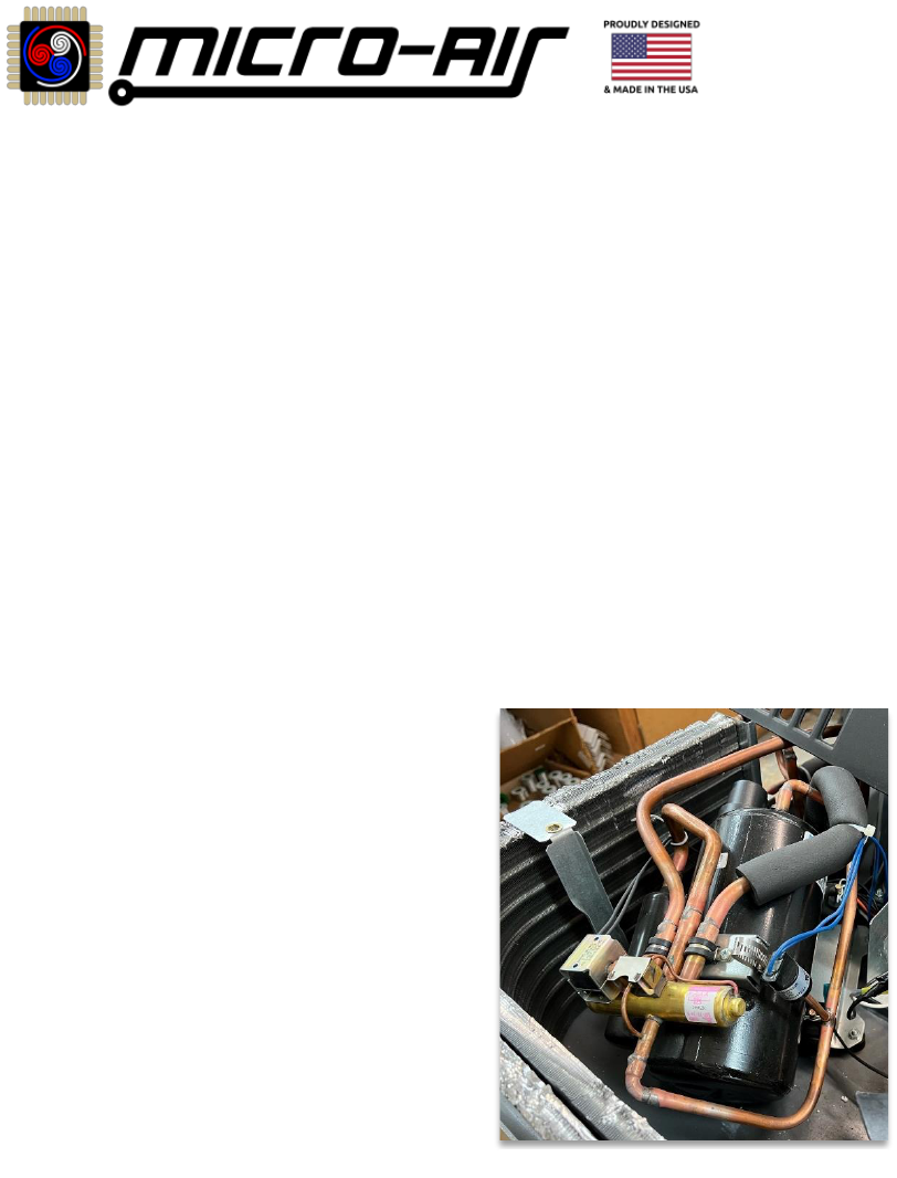
3. Identify the Compressor Motor
Somewhere in the A/C unit enclosure is the compressor motor
itself. It is an oval or pill shaped metal housing, usually black
and 12” or more long. It will have copper tubing entering and
exiting the housing, as well as some wires for electrical
connection. A typical compressor is shown in Figure 4.
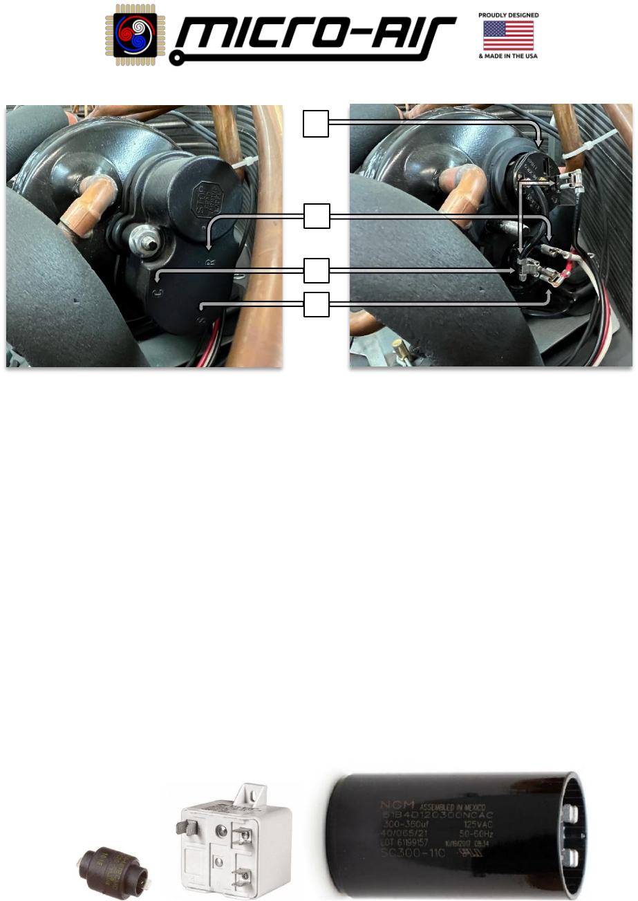
4. Identify the Three Compressor Wires (C, S, and R)
The windings of the compressor motor are accessible by three
wires that exit the motor housing. These three wires are called
“C”, “S”, and “R”, and we want to identify them. There is usually
a cover on the motor housing that protects where the wires exit
the housing. A typical wire cover is shown in Figure 5.
Some wire covers have the windings labeled on top of it. Others
may have the label stamped on the compressor housing
exterior near the cover. You may have to remove the cover to identify each wire’s appropriate name.
Match the three wires with their associated electrical representation of “C”, “S”, and “R”. When we know
this, we can generically install EasyStart in any system. A compressor with the wire cover removed is
shown in Figure 6. The compressor “C” wire may rout through an overload switch (OL), also shown in
Figure 6. The OL must be undisturbed and can be considered a continuation of the “C” wire for installation.
5. Trace Out the Three Compressor Wires (C, S, and R)
Typically, the three compressor wires when traced out will land in an electric box in the A/C unit enclosure.
Use the following sections to make specific checks when tracing out the wires.
Figure 4 - Compressor Motor
EasyStart Advanced Troubleshooting Guide
9
©2022 Micro-Air Corp April 20, 2022, revision 2.0
6. Trace Out the Compressor “S” Wire and Splice in EasyStart Orange
Follow the compressor “S” wire to where it lands. This is typically in the A/C enclosure’s electric box. It
will always be eventually or directly connected to the “H” or “HERM” terminal of the run capacitor.
EasyStart orange must be spliced somewhere into this compressor “S” circuit. EasyStart orange can be slid
onto the “HERM” terminal group in installations where this is accessible. Ensure that terminals are mated
properly, slid into their metal housings and not pinched between the plastic housing.
See section Identifying the Run Capacitor Connections and Terminals for more details if needed.
7. Inspect the Run Capacitor for Factory Start Components and Remove Them if Found
Follow the compressor “S” wire to where it lands. Inspect this junction for any other connections to any
other components. This junction may be the run capacitor “H” terminal itself, or a terminal block that
eventually connects to the “H” terminal. Trace any other wires you find at this junction to their end. If you
find they go to start components (start relay, start capacitor, or PTCR) then this wire must be removed by
disconnecting this connection at both ends. This wire will exist if you have start components. If and only
if you cannot remove this wire from both ends then remove the component entirely. Figure 7 shows
examples of start components you may find that must be disconnected as described. See section
Identifying the Run Capacitor Connections and Terminals for more details if needed.
Figure 7 - Example of (from left) PTCR, Start Relay, Start Capacitor
Figure 5 - Compressor Wire Cover
Figure 6 - Compressor Wire Cover Removed
OL
C
R
S

EasyStart Advanced Troubleshooting Guide
10
©2022 Micro-Air Corp April 20, 2022, revision 2.0
8. Trace Out the Compressor “R” Wire and Connect it Directly with EasyStart Brown
Follow the compressor “R” wire to where it lands. This is typically in the A/C enclosure’s electric box. The
compressor “R” wire should be disconnected or (if no other option) cut from any factory electrical
connection and connected exclusively with EasyStart brown.
Pay close attention to the compressor “R” wire to ensure you have it traced out properly. Often, the
compressor “R” wire is the same color and thickness as several other wires in the electric box and so is
easy to mis-identify. Smaller sized A/C units usually have compressor “R” wire landed on the top of the
run capacitor “C” terminal, which is a power leg terminal. Larger units will have it connected to the power
leg directly, or through a relay or contactor.
9. EasyStart White is Landed Where Compressor “R” was Pulled From
EasyStart white must be connected to the power leg (we will call it “L2”, as per Figure 3) that compressor
“R” was connected to. You can land EasyStart white wherever you pulled the compressor “R” wire from.
Consult the factory schematic if you are not sure where compressor “R” was previously landed.
In any application, the compressor “R” wire from the factory is connected to “L2” directly, or through a
switch. EasyStart white must be connected to the same power leg in an appropriate fashion.
WARNING: Compressor “R”, and now EasyStart white, carry the majority of compressor current. This
connection point where EasyStart white is landed must be rated for compressor currents. In smaller
systems that use our EasyStart 364, this can be the run capacitor “C” terminal. In larger systems that
use our EasyStart 368, it must be on the main power contactor or relay terminal, separate from run
capacitor “L2”. Run capacitor terminals are not rated for compressor currents of larger systems.
10. Trace Out the Compressor “C” Wire and Splice in EasyStart Black
Follow the compressor “C” wire to where it lands. This may be inside the A/C enclosure’s electric box.
Some systems have the wire landed down in the plenum at the control box. These systems may route the
wire through the A/C enclosure’s electric box, or straight down to the plenum from the compressor.
EasyStart black must be spliced into this compressor “C” wire wherever most convenient. This is typically
in the A/C electric box but almost always at least in the A/C enclosure.
The compressor “C” wire may rout through an overload switch mounted in the compressor housing, as
shown in Figure 6. EasyStart black must be spliced into compressor “C” from outside of the wire cover.
That is, the short wire shown should be preserved and the splice made somewhere away from the cover.
In systems where you cannot simply land EasyStart black alongside compressor “C”, a common approach
is to create a three-wire pigtail on the end of the EasyStart black wire. You can then pull the compressor
“C” wire, land one of the pigtail wires where you pulled compressor “C”, and connect compressor “C” into
the pigtail. In systems where you cannot access the landing, you can cut the compressor “C” wire at a
convenient location and create a three-way crimp. You may need to extend the length of the EasyStart
black wire with similar 14 AWG copper wire to reach where you can make the connection.

EasyStart Advanced Troubleshooting Guide
11
©2022 Micro-Air Corp April 20, 2022, revision 2.0
Identifying the Run Capacitor Connections and Terminals
Run capacitors can be in two styles as shown in Figure 8, where there are two terminal groups (left) or
three terminal groups (right). Three terminal group capacitors should have their terminals labelled as “F”
or “FAN”, “H” or “HERM” and “C”. Two terminal group run capacitors are always “H” and “C”, though
unmarked. Figure 9 shows the profile view of a typical run capacitor.
The “F” terminal of three-terminal run capacitors will always have the appropriate fan connection to it
only. This is undisturbed by an EasyStart installation.
The “H” terminal will always have the compressor “S” wire attached to it, either directly or through a
connecting wire. You can use this to identify a two-terminal group run capacitor terminal name. The “C”
terminal is for a power leg connection to the run capacitor. It should always have this power leg
connection. It may have other “C” terminal connections for other components (reversing valves, pumps,
compressor “R”, etc.), depending on your application.
A two-terminal run capacitor is a bi-directional device. The terminals are unmarked because you can use
either group as “H” or “C”. If you are unsure how a two-terminal capacitor is being used or labeled and
has become mis-wired, you can pull everything off and reconnect it using either terminal as needed.
Figure 10 shows a typical drawing of a run capacitor as described above. The solid elements must be
present in any application. The translucent elements may or may not be in your application. The wire
colors shown are common for their purpose but may be different colors in your application. Note the
terminal markings and “FAN” terminal itself are also optional.
Figure 11 shows a typical EasyStart installation overlayed a typical factory installation. Note that if the
translucent components are not in your system then it may not be relevant to your EasyStart installation
as shown. If you do have them then it should be handled as shown, and described in the relevant Table 1
- EasyStart Wiring Checklist step. Note: Figure 11 shows EasyStart white connected to the “C” terminal
of the run capacitor. This should only be done for systems with EasyStart 364 models. EasyStart 368
models should have its white wire connected directly to L2 through the main A/C unit contactor or relay
terminal. See the appropriate Table 1 - EasyStart Wiring Checklist step and description for more details.
Figure 8 - Run Capacitor Tops
Figure 9 - Run Capacitor Profile

EasyStart Advanced Troubleshooting Guide
12
©2022 Micro-Air Corp April 20, 2022, revision 2.0
Figure 10 - Factory Run Capacitor Connections
Figure 11 - Run Capacitor with EasyStart Connections

EasyStart Advanced Troubleshooting Guide
13
©2022 Micro-Air Corp April 20, 2022, revision 2.0
Section 3 – The Compressor Has Never Started on Utility Power
Proceed into this section when the answer is YES to ALL of these questions:
• Before EasyStart first installed:
o The compressor runs normally on utility power?
• With EasyStart first installed:
o The compressor does not and has never started on the same utility power?
Pre-Checklist
• Set the thermostat to off
• Wait at least 6 minutes from the last attempt to call for the compressor
• Connect your system to utility power or a large (running) generator
• Close all breakers between the power source and the A/C unit
• Set the thermostat to call for a compressor cycle
• Monitor compressor operation for the next 3 minutes
My RV Thermostat Now Has an Error Code or No Power
My RV Thermostat No Longer Has Certain Modes
A proper EasyStart installation does not affect the thermostat operation or its error checking. Some A/C
control boards are configured using DIP switches on the board itself. These or the thermostat wiring may
have been accidentally disturbed during EasyStart’s installation. Use the thermostat owner’s manual or
service manual to verify the thermostat wires are still connected and any switches are set appropriately.
• If you are missing a mode (ex. Furnace mode), ensure the (ex. Furnace) mode switch is set
• If you are missing a zone, ensure the zone selection switches are correct and the communication
wires are connected
• If you have no thermostat power, ensure the power wires are still connected
Use the thermostat owner’s manual to identify and troubleshoot other error codes. No other errors
should be as a result of EasyStart, however you can use the Micro-Air Contact Us Page for more assistance.
My Home Thermostat or Home A/C Control Board is Throwing a Fault
Some home units do not expect the EasyStart hardware and throw a fault when it detects EasyStart. By
default, EasyStart has the compressor run winding disconnected for a few seconds to allow a fan motor
to stabilize. This delay must be turned off in these systems that check for it. The faults are usually called
“Open Run Winding” or “No Compressor Operation” or similar.
Please use the relevant section in our EasyStart Generic Home Installation Guide for how to configure
EasyStart for these systems.
Use the A/C owner’s manual or fault sheet to troubleshoot other kinds of faults. No other faults should
be as a result of EasyStart, however you can use the Micro-Air Contact Us Page for further assistance.

EasyStart Advanced Troubleshooting Guide
14
©2022 Micro-Air Corp April 20, 2022, revision 2.0
My Compressor Does Not Try to Start
Once the thermostat determines a cycle is needed, it should start the compressor within 3 minutes if
the
Pre-Checklist is followed. No compressor operation suggests that EasyStart is not powered, has a wiring
issue, or a problem with this particular EasyStart.
• Ensure that all steps in the
• Pre-Checklist section are completed
• Remove AC Line Voltage
• Verify that EasyStart is wired properly using Section 2 – Wiring Installation Resources
o Common wiring issues for this behavior:
▪ EasyStart orange is not connected to the run capacitor “HERM” terminal circuit
▪ The compressor “S” wire was removed from the run capacitor “HERM” terminal
▪ The run capacitor “C” terminal does not have its power leg connection
▪ Any prior start components were not removed from the “HERM” terminal 2DO
▪ EasyStart black is not spliced into or alongside the compressor “C” wire
▪ The compressor “C” wire is not still (electrically) connected where it used to be
• Verify the compressor is truly not attempting to start
o Restore AC Line Voltage (SEE SECTION WARNING) and call for a cycle using the
o Pre-Checklist
o RV units or smaller unit’s compressors can sometimes be hard to hear over the fan. Have an
assistant use the
o Pre-Checklist section directions while you place your hand on the compressor motor. Feel for
vibration to know its behavior:
▪ Before the fan motor starts: no vibration
▪ The fan motor starts and runs: some residual vibration on the compressor from the fan
▪ During the 3 minutes after the fan: Compressor shakes on startup and its running vibration.
The vibration felt from the fan will not change if the compressor is not starting
o Home units or larger unit’s compressors typically have a much more distinct sound over the fan
to determine if it is attempting to start
o Use a clamp-on ammeter around the EasyStart white wire and look for any change in reading
o If the compressor is actually starting then go to the appropriate section
▪ The A/C System Fans Do Not Spin or Not at the Same Speed as Before
A proper EasyStart installation cannot affect the fan operation in any way. Any fans should turn on the
same as they always have. This suggests a wiring issue or a power delivery issue outside of EasyStart itself.
If the compressor also does not start then use section My Compressor Does Not Try to Start first.
Note: EasyStart introduces a 5-10 second delay between the fan and compressor starting to allow the
fan motor to spin up at a different time than the compressor. This is normal operation.
• Ensure that all steps in the

EasyStart Advanced Troubleshooting Guide
15
©2022 Micro-Air Corp April 20, 2022, revision 2.0
• Pre-Checklist section are completed
• Remove AC Line Voltage
• Verify that the fan can spin freely without restriction from debris or routed wires
• Verify that EasyStart is wired properly using Section 2 – Wiring Installation Resources
o Ensure that you have EasyStart interfaced properly with the Run Capacitor. Make sure incoming
power (typically L2/Neutral) is connected to the run capacitor “C” terminal. If you have a three
terminal group run capacitor, the “FAN” terminal is for the appropriate fan wire.
▪ If there is no operation at all from the compressor or fan, there is likely a wiring issue that
has disconnected power from the entire A/C unit.
o Ensure the (if used) separate fan capacitor is undisturbed and connected per factory. These
typically have oval tops instead of run capacitor circular tops.
• Verify that the fan motor is wired properly. There are usually 3 groups of wires for the fan motor:
o Speed: One, two, or three wires select speed and have one power leg (typically L1/Hot) connect
to it one at a time, through the A/C control board.
o Power: One wire is always connected to the other power leg (typically L2/Neutral) that is
opposite the speed wire power leg.
o Capacitor: One wire is always connected to a fan capacitor on one side. This could be the “FAN”
terminal of the run capacitor. The other fan capacitor side or the run capacitor “C” terminal
must connect to the other power leg (typically L2/Neutral) that is opposite the speed wire
power leg.
• Verify line voltage is across the motor wires with an AC voltmeter
o Restore AC Line Voltage (SEE SECTION WARNING) and call for the fan to spin
▪ STAY CLEAR of the fan spin path should it begin rotating at any time
o Set the meter to read AC line voltage. Place one probe on the appropriate speed wire and one
on the power wire at an available contact point in the A/C enclosure.
▪ No voltage suggests something earlier in this section is not verified correctly or a problem
with the fan controller.
▪ Full line voltage suggests where you probed is correct, but there may be a wiring problem
“closer” to the motor in the circuit. Full line voltage at the fan motor terminals suggests a
fan capacitor or fan motor problem.
▪ Low voltage suggests a fan capacitor, fan motor, or wire joint issue causing an abnormal
voltage drop.

EasyStart Advanced Troubleshooting Guide
16
©2022 Micro-Air Corp April 20, 2022, revision 2.0
▪ Section 4 – The Compressor Starts on Utility Power but Not Satisfactorily
• Inspect the EasyStart Indicator Lights using SECTION 2DO
o Faults meaning the compressor attempts to start; navigate to The A/C System Fans Do Not Spin
or Not at the Same Speed as Before
A proper EasyStart installation cannot affect the fan operation in any way. Any fans should turn on the
same as they always have. This suggests a wiring issue or a power delivery issue outside of EasyStart itself.
If the compressor also does not start then use section My Compressor Does Not Try to Start first.
Note: EasyStart introduces a 5-10 second delay between the fan and compressor starting to allow the
fan motor to spin up at a different time than the compressor. This is normal operation.
• Ensure that all steps in the
• Pre-Checklist section are completed
• Remove AC Line Voltage
• Verify that the fan can spin freely without restriction from debris or routed wires
• Verify that EasyStart is wired properly using Section 2 – Wiring Installation Resources
o Ensure that you have EasyStart interfaced properly with the Run Capacitor. Make sure incoming
power (typically L2/Neutral) is connected to the run capacitor “C” terminal. If you have a three
terminal group run capacitor, the “FAN” terminal is for the appropriate fan wire.
▪ If there is no operation at all from the compressor or fan, there is likely a wiring issue that
has disconnected power from the entire A/C unit.
o Ensure the (if used) separate fan capacitor is undisturbed and connected per factory. These
typically have oval tops instead of run capacitor circular tops.
• Verify that the fan motor is wired properly. There are usually 3 groups of wires for the fan motor:
o Speed: One, two, or three wires select speed and have one power leg (typically L1/Hot) connect
to it one at a time, through the A/C control board.
o Power: One wire is always connected to the other power leg (typically L2/Neutral) that is
opposite the speed wire power leg.
o Capacitor: One wire is always connected to a fan capacitor on one side. This could be the “FAN”
terminal of the run capacitor. The other fan capacitor side or the run capacitor “C” terminal
must connect to the other power leg (typically L2/Neutral) that is opposite the speed wire
power leg.
• Verify line voltage is across the motor wires with an AC voltmeter
o Restore AC Line Voltage (SEE SECTION WARNING) and call for the fan to spin
▪ STAY CLEAR of the fan spin path should it begin rotating at any time
o Set the meter to read AC line voltage. Place one probe on the appropriate speed wire and one
on the power wire at an available contact point in the A/C enclosure.
▪ No voltage suggests something earlier in this section is not verified correctly or a problem
with the fan controller.
EasyStart Advanced Troubleshooting Guide
17
©2022 Micro-Air Corp April 20, 2022, revision 2.0
▪ Full line voltage suggests where you probed is correct, but there may be a wiring problem
“closer” to the motor in the circuit. Full line voltage at the fan motor terminals suggests a
fan capacitor or fan motor problem.
▪ Low voltage suggests a fan capacitor, fan motor, or wire joint issue causing an abnormal
voltage drop.

EasyStart Advanced Troubleshooting Guide
18
©2022 Micro-Air Corp April 20, 2022, revision 2.0
o Section 4 – The Compressor Starts on Utility Power but Not Satisfactorily
▪ Power Interruption, Stall, Overcurrent, Overload Open, Unexpected Current
o Mis-wiring, wiring section 2DO
o No LEDs, verify power see section 2DO

EasyStart Advanced Troubleshooting Guide
19
©2022 Micro-Air Corp April 20, 2022, revision 2.0
The A/C System Fans Do Not Spin or Not at the Same Speed as Before
A proper EasyStart installation cannot affect the fan operation in any way. Any fans should turn on the
same as they always have. This suggests a wiring issue or a power delivery issue outside of EasyStart itself.
If the compressor also does not start then use section My Compressor Does Not Try to Start first.
Note: EasyStart introduces a 5-10 second delay between the fan and compressor starting to allow the
fan motor to spin up at a different time than the compressor. This is normal operation.
• Ensure that all steps in the
• Pre-Checklist section are completed
• Remove AC Line Voltage
• Verify that the fan can spin freely without restriction from debris or routed wires
• Verify that EasyStart is wired properly using Section 2 – Wiring Installation Resources
o Ensure that you have EasyStart interfaced properly with the Run Capacitor. Make sure incoming
power (typically L2/Neutral) is connected to the run capacitor “C” terminal. If you have a three
terminal group run capacitor, the “FAN” terminal is for the appropriate fan wire.
▪ If there is no operation at all from the compressor or fan, there is likely a wiring issue that
has disconnected power from the entire A/C unit.
o Ensure the (if used) separate fan capacitor is undisturbed and connected per factory. These
typically have oval tops instead of run capacitor circular tops.
• Verify that the fan motor is wired properly. There are usually 3 groups of wires for the fan motor:
o Speed: One, two, or three wires select speed and have one power leg (typically L1/Hot) connect
to it one at a time, through the A/C control board.
o Power: One wire is always connected to the other power leg (typically L2/Neutral) that is
opposite the speed wire power leg.
o Capacitor: One wire is always connected to a fan capacitor on one side. This could be the “FAN”
terminal of the run capacitor. The other fan capacitor side or the run capacitor “C” terminal
must connect to the other power leg (typically L2/Neutral) that is opposite the speed wire
power leg.
• Verify line voltage is across the motor wires with an AC voltmeter
o Restore AC Line Voltage (SEE SECTION WARNING) and call for the fan to spin
▪ STAY CLEAR of the fan spin path should it begin rotating at any time
o Set the meter to read AC line voltage. Place one probe on the appropriate speed wire and one
on the power wire at an available contact point in the A/C enclosure.
▪ No voltage suggests something earlier in this section is not verified correctly or a problem
with the fan controller.
▪ Full line voltage suggests where you probed is correct, but there may be a wiring problem
“closer” to the motor in the circuit. Full line voltage at the fan motor terminals suggests a
fan capacitor or fan motor problem.
▪ Low voltage suggests a fan capacitor, fan motor, or wire joint issue causing an abnormal
voltage drop.

EasyStart Advanced Troubleshooting Guide
20
©2022 Micro-Air Corp April 20, 2022, revision 2.0

EasyStart Advanced Troubleshooting Guide
21
©2022 Micro-Air Corp April 20, 2022, revision 2.0
Section 4 – The Compressor Starts on Utility Power but Not Satisfactorily
Proceed into this section when the answer is YES to ALL of these questions:
• Before EasyStart first installed:
o The compressor runs normally on utility power?
• With EasyStart first installed:
o The compressor starts, but shuts down prematurely or is not the right air temperature?
Pre-Checklist
• Set the thermostat to off
• Wait at least 6 minutes from the last attempt to call for the compressor
• Connect your system to utility power or a large (running) generator
• Close all breakers between the power source and the A/C unit
• Set the thermostat to call for a compressor cycle
• Monitor compressor operation for the next 3 minutes
Once the thermostat determines a cycle is needed, it should start the compressor within 3 minutes if the
Pre-Checklist is followed. This section is when you can see, feel, or hear the compressor attempt a start
(not just the fan!), but there is some problem with its operation thereafter. The ability to cool should be
exactly the same as it could prior to EasyStart installation in normal operation.
I Fixed a Wiring Issue but Now the Compressor is/still is Shutting Down Prematurely
During installation, you may have applied power to the system while a wiring error existed. Most wiring
errors will be caught by EasyStart, however if invalid data was saved, EasyStart may need to have its
memory cleared. Bad saved data may be erroneously tripping faults after a wiring error is resolved.
Ensure that all steps in the Pre-Checklist
• Pre-Checklist section are completed
• Remove AC Line Voltage
• Verify that EasyStart is wired properly using Section 2 – Wiring Installation Resources
o You may have resolved one wiring issue but more may exist
o Common wiring issues that may call for a Re-learn (Factory Reset) once resolved
▪ Wired EasyStart into the fan motor rather than the compressor motor
▪ Compressor “R” wire was connected to both EasyStart brown and power leg “L2”
• Inspect the EasyStart Indicator Lights using SECTION 2DO
o If you have the Wiring Error Fault, there is still a wiring issue that must be addressed
o Perform a Re-learn (Factory Reset) on EasyStart when appropriate 2DO

EasyStart Advanced Troubleshooting Guide
22
©2022 Micro-Air Corp April 20, 2022, revision 2.0
The A/C System Fans Do Not Spin or Not at the Same Speed as Before
A proper EasyStart installation cannot affect the fan operation in any way. Any fans should turn on the
same as they always have. This suggests a fan wiring issue outside of EasyStart itself. If the compressor is
not starting then use Section 3 – The Compressor Has Never Started on Utility Power first.
Note: EasyStart introduces a 5-10 second delay between the fan and compressor starting to allow the
fan motor to spin up at a different time than the compressor. This is normal operation.
• Ensure that all steps in the Pre-Checklist section are completed
• Remove AC Line Voltage
• Verify that the fan can spin freely without restriction from debris or routed wires
• Verify that EasyStart is wired properly using Section 2 – Wiring Installation Resources
o Common wiring issues for this behavior
▪ Wired EasyStart into the fan motor rather than the compressor motor
• Verify that the fan motor is wired properly. There are usually 3 groups of wires for the fan motor:
o Speed: One, two, or three wires select speed and have one power leg (typically L1/Hot) connect
to it one at a time, through the A/C control board.
o Power: One wire is always connected to the other power leg (typically L2/Neutral) that is
opposite the speed wire power leg.
o Capacitor: One wire is always connected to a fan capacitor on one side. This could be the “FAN”
terminal of the run capacitor. The other fan capacitor side or the run capacitor “C” terminal
must connect to the other power leg (typically L2/Neutral) that is opposite the speed wire
power leg.
• Verify line voltage is across the motor wires with an AC voltmeter
o Restore AC Line Voltage (SEE SECTION WARNING) and call for the fan to spin
▪ STAY CLEAR of the fan spin path should it begin rotating at any time
o Set the meter to read AC line voltage. Place one probe on the appropriate speed wire and one
on the power wire at an available contact point in the A/C enclosure.
▪ No voltage suggests something earlier in this section is not verified correctly or a problem
with the fan controller.
▪ Full line voltage suggests where you probed is correct, but there may be a wiring problem
“closer” to the motor in the circuit. Full line voltage at the fan motor terminals suggests
something earlier in this section is not verified correctly, or a fan capacitor or fan motor
problem.
▪ Low voltage suggests a fan capacitor, fan motor, or wire crimp/splice joint issue causing
an abnormal voltage drop.

EasyStart Advanced Troubleshooting Guide
23
©2022 Micro-Air Corp April 20, 2022, revision 2.0
My Compressor Tries to Start but Fails, Runs Only for a Couple Seconds at Most
EasyStart performs a multi-step ramping process to gently bring the motor up to speed. EasyStart checks
a few parameters to control this process and ensure is operating normally. We need to determine why
the compressor is shutting down, which could be an EasyStart fault or something outside the EasyStart
System.
Ensure that all steps in the Pre-Checklist
• Pre-Checklist section are completed
• Remove AC Line Voltage
o It is important that a power source that could start the A/C without EasyStart is used
• Verify that EasyStart is wired properly using Section 2 – Wiring Installation Resources
o Common wiring issues for this behavior
▪ EasyStart black is not spliced into or alongside the compressor “C” wire
▪ Compressor “R” wire is connected to both EasyStart brown and power leg “L2”
▪ Bad crimps/splice joints causing a voltage drop
• Inspect the EasyStart Indicator Lights using SECTION 2DO
o Stall see section 2DO
o Overcurrent see section 2DO
o No LEDs, verify power see section 2DO
My Compressor Starts and Runs for at least 10 Seconds, but Eventually Shuts Down Prematurely
EasyStart performs most of its function on motor startup and is about a 10 second process. After that,
EasyStart is a closed switch, running the compressor motor as it always did. EasyStart is then only
monitoring for faults. If a fault is detected, it will disconnect the compressor to shut it down. We need to
determine why the compressor is shutting down, which could be that EasyStart detected a fault or
something outside the EasyStart system.
Ensure that all steps in the Pre-Checklist
• Pre-Checklist section are completed
• Remove AC Line Voltage
o It is important that a power source that could start the A/C without EasyStart is used
• Verify that EasyStart is wired properly using Section 2 – Wiring Installation Resources
o Common wiring issues for this behavior
▪ EasyStart black is not spliced into or alongside the compressor “C” wire
▪ Compressor “R” wire is connected to both EasyStart brown and power leg “L2”
▪ Bad crimps/splice joints causing a voltage drop
• Inspect the EasyStart Indicator Lights using SECTION 2DO
o Stall see section 2DO
o Overcurrent see section 2DO
o No LEDs, verify power see section 2DO

EasyStart Advanced Troubleshooting Guide
24
©2022 Micro-Air Corp April 20, 2022, revision 2.0
My Compressor Runs, However it Cools in Heat Pump Mode or Heats in Cool Mode
You may find that your compressor is making noise, vibrating, and/or running appropriately, however the
air being produced is tempered the wrong way based on what mode the thermostat is in. This is almost
always a wiring issue developed during EasyStart installation, where the reversing valve has become
disconnected from its control. It is meant to open or close to create heat or cool and miswiring has
disturbed this operation.
This is not the same as no cooling or heat with a running compressor. See section 2DO for help in this
scenario.
• Remove AC Line Voltage
• Verify that the reversing valve is wired properly
o The reversing valve will have two wires that have line voltage connected to it to turn it on and
off. One wire will go to a control board or wire to connect a power leg (typically “L1”) that is
switched. The other wire will go to the opposite power leg “L2” wire or control board terminal.
▪ Look over your schematic for a reversing valve and note how it is wired
▪ Figure 4 shows a reversing valve. It is the yellow tube with two black wires
o Ensure the two reversing valve wires are landed appropriately
o Some manufactures will land the “L2” reversing valve connection on the compressor motor
start capacitor. If you completely disconnected the start capacitor while installing EasyStart
then you may have defeated the reversing valve circuit. Land the reversing valve “L2” wire on
the run capacitor “C” terminal to restore the circuit in these systems.

EasyStart Advanced Troubleshooting Guide
25
©2022 Micro-Air Corp April 20, 2022, revision 2.0
Section 5 – The A/C Has Problems Running on Limited Power
Proceed into this section when the answer is YES to ALL of these questions:
• Before EasyStart first installed:
o The compressor runs normally on utility power?
• With EasyStart first installed:
o The compressor starts and runs satisfactorily on the same utility power?
o The A/C unit does not start or run satisfactorily on limited power (genset, inverter, etc.)?
Pre-Checklist
• Set the thermostat to off
• Wait at least 6 minutes from the last attempt to call for the compressor
• Connect your system to your limited power source (small generator, inverter, etc.)
• Close all breakers between the power source and the A/C unit
• Set the thermostat to call for a compressor cycle
• Monitor compressor operation for the next 3 minutes
The A/C System Fans Do Not Spin When Called For
A proper EasyStart installation cannot affect the fan operation in any way. Any fans should turn on the
same as they always have. First, verify that everything operates normally on utility power by reassessing
where you are in the Problem Characterization Figure 1 chart. Return if everything works on utility power.
• Ensure there is no issue operating the unit on utility power
Ensure that all steps in the Pre-Checklist
• Pre-Checklist section are completed
• Ensure any inverter systems are not throwing any faults, preventing output of power
• Verify line voltage can reach the A/C unit
o Go to the inverter output and follow it to the breaker or bus it is connected to. Also, work back
from the A/C unit to the A/C breaker. The inverter is likely not wired into the A/C breaker.
o Limited power systems are sometimes not connected to main power buses or A/C power
busses, as those limited power systems cannot handle the load without EasyStart. As such,
many RV builders will not connect their inverter system to the main power bus. This means you
must install an interlock switch between utility and inverter power so you can switch the
inverter into the main power bus. Some inverters allow being on the main bus directly without
an interlock switch. Above all, some type of rewiring is required in these systems. Micro-Air
cannot assist with this type of work.
o Typically, generators are already wired into the line directly or through an interlock switch.

EasyStart Advanced Troubleshooting Guide
26
©2022 Micro-Air Corp April 20, 2022, revision 2.0
My Compressor Does Not Try to Start
Once the thermostat determines a cycle is needed, it should start the compressor within 3 minutes if the
Pre-Checklist is followed. No compressor operation suggests that EasyStart is not powered or has a wiring
issue.
Ensure that all steps in the Pre-Checklist
• Pre-Checklist section are completed
• Remove AC Line Voltage
• Verify that EasyStart is wired properly using Section 2 – Wiring Installation Resources
o Common wiring issues for this behavior:
▪ Wiring has become loose
▪ Factory Start components are still in circuit
▪ Compressor “R” wire is connected to both EasyStart brown and power leg “L2”
▪ EasyStart black is not spliced into or alongside the compressor “C” wire
• Verify the compressor is truly not attempting to start
o Restore AC Line Voltage (SEE SECTION WARNING) and call for a cycle using the Pre-Checklist
o RV units or smaller unit’s compressors can sometimes be hard to hear over the fan. Have an
assistant use the Pre-Checklist section directions while you place your hand on the compressor
motor. Feel for vibration to know its behavior:
▪ Before the fan motor starts: no vibration
▪ The fan motor starts and runs: some residual vibration on the compressor from the fan
▪ During the 3 minutes after the fan: Compressor shakes on startup and its running vibration.
The vibration felt from the fan will not change if the compressor is not starting
o Home units or larger unit’s compressors typically have a much more distinct sound over the fan
to determine if it is attempting to start
o Use a clamp-on ammeter around the EasyStart white wire and look for any change in reading
o If the compressor is actually starting then go to the appropriate section
▪ My Compressor Does Not Try to Start
• Inspect the EasyStart Indicator Lights using SECTION 2DO
o Faults meaning the compressor attempts to start; go to My Compressor Does Not Try to Start
▪ Power Interruption, Stall, Overcurrent, Overload Open, Unexpected Current
o Mis-wiring, wiring section 2DO
o No LEDs, verify power see section 2DO

EasyStart Advanced Troubleshooting Guide
27
©2022 Micro-Air Corp April 20, 2022, revision 2.0
My Compressor Tries to Start and Fails, Runs Only For a Few Seconds at Most
EasyStart performs a multi-step ramping process to gently bring the motor up to speed. EasyStart checks
a few parameters to control this process and ensure is operating normally. We need to determine why
the compressor is shutting down, which could be an EasyStart fault or something outside the EasyStart
System.
Ensure that all steps in the Pre-Checklist
• Pre-Checklist section are completed
• Remove AC Line Voltage
o It is important that a power source that could start the A/C without EasyStart is used
• Verify that EasyStart is wired properly using Section 2 – Wiring Installation Resources
o Common wiring issues for this behavior
▪ Factory Start components are still in circuit
▪ EasyStart black is not spliced into or alongside the compressor “C” wire
▪ Compressor “R” wire is connected to both EasyStart brown and power leg “L2”
▪ Bad crimps/splice joints causing a voltage drop
• Inspect the EasyStart Indicator Lights using SECTION 2DO
o Stall see section 2DO
o Overcurrent see section 2DO
o No LEDs, verify power see section 2DO
My Compressor Starts and Runs for at least 10 Seconds, but Eventually Shuts Down Prematurely
EasyStart performs most of its function on motor startup and is about a 10 second process. After that,
EasyStart is a closed switch, running the compressor motor as it always did. EasyStart is then only
monitoring for faults. If a fault is detected, it will disconnect the compressor to shut it down. We need to
determine why the compressor is shutting down, which could be that EasyStart detected a fault or
something outside the EasyStart system.
Ensure that all steps in the Pre-Checklist
• Pre-Checklist section are completed
• Remove AC Line Voltage
o It is important that a power source that could start the A/C without EasyStart is used
• Verify that EasyStart is wired properly using Section 2 – Wiring Installation Resources
o Common wiring issues for this behavior
▪ EasyStart black is not spliced into or alongside the compressor “C” wire
▪ Compressor “R” wire is connected to both EasyStart brown and power leg “L2”
▪ Bad crimps/splice joints causing a voltage drop
• Inspect the EasyStart Indicator Lights using SECTION 2DO
o Stall see section 2DO
o Overcurrent see section 2DO
o No LEDs, verify power see section 2DO

EasyStart Advanced Troubleshooting Guide
28
©2022 Micro-Air Corp April 20, 2022, revision 2.0

EasyStart Advanced Troubleshooting Guide
29
©2022 Micro-Air Corp April 20, 2022, revision 2.0
Section 6 – A/C Worked For Some Time But No Longer On Utility Power
Section 7 – A/C Worked For Some Time But No Longer On Limited Power

EasyStart Advanced Troubleshooting Guide
30
©2022 Micro-Air Corp April 20, 2022, revision 2.0
Appendix A – LED Indicator Lights and Troubleshooting Procedures
EasyStart is always checking to make sure the system is functioning normally. This is to prevent damage
and ensure low current starts. The state of these checks and what EasyStart is doing is shown by its
indicator lights on the EasyStart circuit board. Using these can greatly aid the troubleshooting process.
EasyStart and LED Indicator Light Relationship
EasyStart executes a series of steps to start and monitor the compressor motor. Understanding how it
should operate will aid in characterizing if a problem is occurring and how to interpret the LEDs.
EasyStart should be wired so that it receives power only when the compressor is powered. That means it
is off when the thermostat is not calling for cooling and so no LEDs will be lit. Then:
• Power is applied to the compressor and EasyStart when the thermostat calls for cooling
• Immediately, the LEDs will show either the “Normal” or “SCPT” indications.
o “Normal” means the compressor will attempt to start in up to 10 seconds
o “SCPT” will switch to “Normal” after the SCPT expires, see Table 3
• EasyStart activates its fault monitoring system
• EasyStart performs its compressor motor startup and runtime procedures
o “Normal” is shown with a visibly/audibly/measured running compressor when successful
• Power is cut to EasyStart and the compressor shuts down
o No LEDs at shutdown is cut power - which is normal when the thermostat ends a cycle
▪ LEDs may light briefly then extinguish as EasyStart experiences the power loss
• At any point, EasyStart may detect a fault
o LEDs show the fault EasyStart is stopped on and halt the compressor if it was operating
o EasyStart locks out or restarts after (typically) 3 minutes, depending on the fault
▪ A restart will switch back to “Normal” LEDs and repeat from the top of this list
▪ Power must be removed to restart if stopped on a “lockout” fault
▪ The LEDs are shown the entire duration of lockout or pending restart
EasyStart LED Indicator Light Appearance
EasyStart indicator lights can be a solid, always-lit type, or a flashing, on-off sequence, depending on the
model. They are always on the EasyStart circuit board. Opaque lids will need to be removed to inspect the
lights and are always the solid type. Transparent lids allow viewing the LEDs and may be solid or flashing.
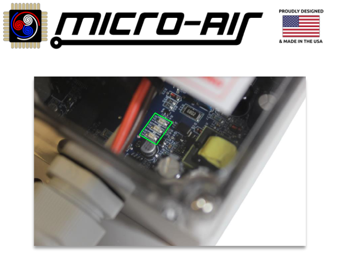
Solid LEDs are labelled D21, D22, and D23 for identification. Error! Reference source not found. shows an
example of the solid LED locations. For flashing types, flash sequences occur in ½ second on/off intervals,
with 1 second of off between repeating sequences. A single flash every second indicates a sequence of 1.
Bluetooth models will have flashing type LEDs. They can also be monitored through the app by connecting
and looking at the system state. It is sometimes best to inspect the Bluetooth model’s LEDs directly for
real-time troubleshooting. Detailed information on Bluetooth model identification and use is described in
the EasyStart Bluetooth Manual.
EasyStart Advanced Troubleshooting Guide
31
©2022 Micro-Air Corp April 20, 2022, revision 2.0
Figure 12 - Solid Version LED Indicator Lights Location
Procedure for Monitoring the LED Indicator Lights
EasyStart LED operation occurs as described in the EasyStart and LED Indicator Light Relationship section.
The following is a procedure to best ensure you view the LEDs appropriately.
• Set the thermostat to off
• Remove A/C line voltage from the system
• Locate where EasyStart is mounted and its LEDs. An opaque lid must be removed by its 4 or 6
screws to view the LEDs. Transparent lids can view the LEDs directly.
• Wait at least 5 minutes from when you removed line voltage to allow any delays to expire
• Restore AC Line Voltage (SEE SECTION WARNING) and set the thermostat to call for a cycle
• Return to the EasyStart and monitor the LEDs and compressor operation. Wait at least 3 minutes
for LEDs to light or for the compressor to start. Place your hand on the compressor to feel if it
kicks in. Larger compressors can typically be heard over the fan. You can also use a clamp-on
ammeter around the compressor “R” or “C” wire and see the current rise.
o No compressor, No LEDs means no power 2DO
o LEDs found can reference Table 2
• Continue if the compressor starts and runs for at least 15 seconds
o Note: Some A/C units have a shroud that allows proper airflow in the system that must
be removed to view the EasyStart LEDs. This means, now that we know the unit starts,
we have to put the cover back on so the system has proper airflow. RV rooftop units are
common examples for these types of systems. Do the following for these systems:
▪ Set the thermostat to off
▪ Leave the EasyStart LEDs exposed and restore the shroud with the screws out
▪ Wait at least 5 minutes and call for another cycle
• Let the A/C run until it shuts down. Look at the LEDs at that time and remove the shroud if needed
o No LEDs or LEDs light briefly then extinguish, power was removed outside of EasyStart
o LEDs found can reference Table 2

EasyStart Advanced Troubleshooting Guide
32
©2022 Micro-Air Corp April 20, 2022, revision 2.0
Table 2 – Indicator Lights Translation Chart
Indication
Solid
D21
D22
D23
Flashes
Resetting
Not Active
All off
none
Normal
All off
solid green
Unexpected Current
ON
1 Red
No
Over-Current
ON
2 Red
Yes
Short-Cycle Prevention Timer is active
1
ON
ON
3 Red or Green
2
Yes
Power Interruption
1
ON
ON
3 Red
Yes
Open Overload
ON
4 Red
Yes
Stall
ON
ON
5 Red
Yes
Wrong Line Voltage
ON
ON
6 Red
No
Mis-Wiring / Start Winding Not Detected
ON
ON
ON
7 Red
No
(1) These faults potentially have the same indication. If found, the LEDs will extinguish soon and another cycle will be attempted.
If the same pattern returns then it is Power Interruption. SCPT is normal EasyStart operation. See note (2) for flashing models.
(2) EasyStart firmware FRM B26 and earlier will flash red for SCPT and FRM B27 and later will flash green.
EasyStart LED Indicator Light Description and Troubleshooting Procedures
This section provides detailed description of the faults listed by Table 2. Use the troubleshooting
procedures to attempt to diagnose and resolve what EasyStart is seeing. Specific procedures may have
been indicated by the Problem Characterization sections. It is OK to start here in this section, however
some LED indications may have more context by using the Problem Characterization section first.
Normal
This state indicates normal operation of EasyStart. Solid LED models with no lit LEDs but a running
compressor is normal operation. No LEDs and no compressor should see the Not Active section. Flashing
LED models will have a solid green power LED, and a solid green status LED.

EasyStart Advanced Troubleshooting Guide
33
©2022 Micro-Air Corp April 20, 2022, revision 2.0
Not Active
This state indicates that EasyStart is not active. Solid LED models with no lit LEDs and no compressor
operation indicate that EasyStart is not active. No LEDs with a running compressor is normal operation for
these models. Flashing type models have a dedicated power LED that is solid green when active, separate
from the flashing status LEDs. “Normal” or stopped on a fault should always be indicated when line voltage
is across the EasyStart white and black wires.
• Set the thermostat to off
• Remove A/C line voltage from the system
• Inspect the EasyStart white and black wires. Black should be connected to compressor “C” for
one power leg (typically “L1”) and white connected to wherever compressor “R” was connected
to from the factory (typically “L2”).
o Use Section 2 – Wiring Installation Resources for a detailed description
• Wait at least 5 minutes from when you removed line voltage to allow any delays to expire
• Restore AC Line Voltage (SEE SECTION WARNING) and set the thermostat to call for a cycle
• Wait an additional 3 minutes to let any thermostat delays expire.
• Use a voltmeter and probe where EasyStart black and white land. You should find full line voltage
when the thermostat is calling for a cycle. No line voltage indicates a wiring or thermostat issue.
You want to measure as close to EasyStart as possible in the circuit to avoid false positives. Use
the Micro-Air Contact Us Page if you have line voltage to EasyStart and no operation.

EasyStart Advanced Troubleshooting Guide
34
©2022 Micro-Air Corp April 20, 2022, revision 2.0
Indication
Description
Not Powered
This indicates that EasyStart is not receiving line voltage across its white and
black wires. For solid LED models, no LEDs and no compressor operation
suggests EasyStart is not powered.
Normal
EasyStart is operating without fault. Solid LED models will have no LEDs when it
is operating normally, so you should have a running compressor motor.
Unexpected Current
EasyStart sees a large current at the beginning of the start process.
Over-Current
The current measured by EasyStart has exceeded the maximum allowed.
SCPT
The Short-Cycle Prevention Timer is active and is normal operation. If the A/C
shuts down and wants to start again in under (typically) 3 minutes, then
EasyStart will prevent starting for the full 3 minutes. This ensures pressure has
equalized in the system and a low current start can occur.
Power Interruption
Power was lost for several AC line voltage cycles and EasyStart shut down to
prevent an overload. It may be normal for this to occur with natural power
disruptions.
Open Overload
EasyStart has detected the compressor overload switch has opened during
operation. This is when continuity is lost between orange and black when the
compressor was running.
Stall
EasyStart is not seeing the condition where it can declare that the compressor
motor is running at the correct speed. This means that the start failed, or the
motor speed was reduced enough to stop the motor after it was running.
Wrong Line Voltage
120VAC only models. EasyStart (-X20 or -T36) has detected the line voltage
exceeds ~150 volts and will not operate.
Mis-Wiring
EasyStart does not have continuity between orange and black
Table 3 - Indicator Lights Description

EasyStart Advanced Troubleshooting Guide
35
©2022 Micro-Air Corp April 20, 2022, revision 2.0
Appendix B – Troubleshooting Procedures
EasyStart Advanced Troubleshooting Guide
36
©2022 Micro-Air Corp April 20, 2022, revision 2.0
Appendix C: Additional Resources
This document references various other Micro-Air resources and are listed here.
EasyStart Knowledge Bank
Where all EasyStart resources are saved, including FAQs, articles, procedures, and troubleshooting guides.
http://www.micro-air.com/kb_easystart.cfm
EasyStart Bluetooth Manual
A manual that describes how to use the EasyStart Bluetooth interface.
http://www.micro-air.com/support-documents/installation_resources/EasyStart_Bluetooth_Manual.pdf
EasyStart Generic Home Installation Guide
A guide for installing in any home system with notes on adapting to a compressor monitoring system.
http://www.micro-air.com/kb-easystart/articles_installation/easystart_Home_AC_Wiring_Guide.cfm
Micro-Air Contact Us Page
Use this page for sending specific inquiries about any of our products
https://www.micro-air.com/contact_microair.cfm
Micro-Air Main Website
https://micro-air.com/
