
WIN-DDE
DYNAMIC DATA EXCHANGE
8525-M278-O1
203 E. Daugherty, Webb City, MO 64870 USA
Printed in USA
Rev 2.19
Ph: 417-673-4631 Fax: 417-673-2153
04/03/07
http://www.cardinalscale.com

1
Win-DDE 2.19
April 03, 2007
Specifications
Cardinal Scale Manufacturing Company offers a complete line of digital weight indicators
supported by the Win-DDE (Dynamic Data Exchange) server. Indicators can be interfaced to any
type of external scale device including truck scales, tank scales, and platform scales.
Up to 20 weight indicators may be connected to a single computer running Win-DDE. The
computer must be properly configured with serial ports or network hardware to allow the
connections. Windows 2000 or XP must be used if more than 10 indicators will be connected.
Numerous types of weight indicators may be used with Win-DDE.
SMA (Scale Manufacturers Association) standard protocol indicators
200 Series weight indicators
777 and 778 weight indicators
738 and 748 weight indicators
Win-DDE may be configured for communications with many other weight indicators
Indicators may be connected to a computer using common connection methods
RS232 standard serial communications ports may be used with simple cabling
TCP/IP network protocol may be used with common Ethernet network cards, hubs, and cables.
The Win-DDE Server allows Windows DDE compatible software products to obtain information
from weight indicators.
Weight string, for example "200 LB G."
Numeric weight. This allows accumulations or calculations.
Scale status, "Motion", "Over Capacity", and "Below Zero" conditions.
Additional field values may be specified.
A print capture mode allows information from an indicator printout including, ID numbers, time
and date, gross, tare and net weights to be automatically sent to an Excel Spreadsheet.
Commands may also be sent to weight indicators.
Zero Scale
Switch between LBS/KGS
Many Windows programs support DDE, including:

2
Industrial control and monitoring: Rockwell Automation RSView, AutomationDirect
LookoutDirect, Wonderware InTouch
Database: Microsoft Access, Microsoft FoxPro
Spreadsheets: Microsoft Excel, Lotus 1-2-3, Novell Quattro Pro
Various configuration settings are available.
DDE topic names, item names
Indicator types
Baud rate, parity, data bits, stop bits
Continuous or on-demand communications
Sample intervals
Weight string format
Win-DDE digital weight indicator DDE client program is also included.
Installation
The Win-DDE software may be installed on a computer with Windows 95, 98, NT 4.0, 2000, or
XP. Windows 2000 or XP is recommended for applications requiring high reliability and
performance.
To begin the installation insert the "Cardinal Scale Manufacturing Company - WinWeigh WIN-
DDE" CD in the CD-ROM drive of the computer.
The installation program will begin. Follow the on screen instructions to complete the
installation. When completed remove the CD from the CD-ROM drive.
Configure the Weight Indicator
Serial Connection
Refer to the Weight Indicator operation manual and configure the weight indicator baud rate and
other communications parameters.
For a Cardinal 200 series indicator perform the following steps:
1. Press the “ON” key to turn on the indicator.
2. Press the “*” and then the “ZERO/REVIEW” key to enter the setup mode.
3. Press “ENTER” repeatedly to step through the setup prompts until “Sio?” is displayed.
4. With “Sio?” displayed press “ENTER”. The display will show “no”. Press the “1/YES”
key to change the display to “YES”. Press “ENTER”.
5. The display will show “bAUd=”. Press “ENTER”. The display may show “96” indicating
9600 baud. If the display does not show “96”, press the “9” and then the “6” key to make
the display show “96”. Press “ENTER”.
3
6. The display will show “PrtY=”. Press “ENTER”. The display may show “0” indicating no
parity. If the display does not show “0”, press the “0” key to make the display show “0”.
Press “ENTER”.
7. The display will show “bits=”. Press “ENTER”. The display may show “8” indicating
eight data bits. If the display does not show “8”, press the “8” key to make the display
show “8”. Press “ENTER”.
8. The display will show “StoP=”. Press “ENTER”. The display may show “1” indicating
one stop bit. If the display does not show “1”, press the “1” key to make the display show
“1”. Press “ENTER”.
9. The display will show “Cont1=”. Press “ENTER”. The display may show “no” indicating
on-demand data output. If the display does not show “no” press the “0/NO” key to make
the display show “no”. Press “ENTER”.
10. The display will show “Cont2=”. Press “ENTER”. The display may show “no” indicating
on-demand data output. If the display does not show “no” press the “0/NO” key to make
the display show “no”. Press “ENTER”.
11. The display will show “Print?” Press “ENTER” repeatedly to step through the remaining
prompts until the normal weight display returns.
12. The indicator is now configured for 9600 baud, no parity, eight data bits, one stop bit, on-
demand output, SMA (Scale Manufacturers Association) format.
Continuous communications may also be used. However, be aware that if the indicator is turned
on and sending continuous data to the computer during Windows startup, Windows may
incorrectly interpret the data. This may cause the computer mouse to behave erratically. The
serial port may not be available to Win-DDE or any Windows applications. To prevent this
occurrence be sure that the weight indicator is turned off during the entire computer power on
and startup process. Configuration changes may be made to the computer to allow continuous
serial data during Windows startup. Please refer to the technical section of this document.
Network TCP/IP Connection
Refer to the Weight Indicator operation manual and configure the weight indicator IP address and
port.
Connecting the Weight Indicator
Serial Connection
Connect the weight indicator to the computer. For a 200 series indicator use a 8545-B099-1A
cable. For a Cardinal 738 or 748 indicator use an 8510-C304-GA cable. If the computer has a 9-
pin serial port attach a 9/25 adapter, 6600-0555 to the cable. The PC end of the cable or the 9/25
adapter should be attached to one of the serial ports on the computer. The serial port must be
properly configured for operation in Windows. The Control Panel / System / Device Manager
may be used to verify the existence of the communications ports. The indicator end of the cable
should be attached to the appropriate serial port on the weight indicator.
Network TCP/IP Connection
4
The computer must have a properly configured network card. If the computer is connected to a
group of other computers a port may be available on a network hub or switch to connect the
indicator. If no ports are available it will be necessary to add a new network hub or switch to
provide additional connection ports. A normal straight-through Ethernet cable can be used to
connect the indicator to the hub or switch. If the indicator is to be connected directly to a network
card on the computer an Ethernet crossover cable must be used.
Starting the DDE Server
DDE (Dynamic Data Exchange) is the key element to the Win-DDE software. A DDE Server is a
program which provides information to other windows programs, known as client programs. The
server may be started in several ways.
• Click “Start” and select “Programs”, “WinDDE” and “WinDDE” server.
• Use “My Computer” or “Windows Explorer” to browse to the WinDDE program
folder. Double-click the "WINDDE.EXE" file in the file manager or explorer.
• Run a DDE client program which has the ability to automatically start the
requested DDE server.
A special startup feature is provided. Holding the shift-key down while starting Win-DDE will
cause Win-DDE to start without enabling the device communications. This may be useful if the
database has incorrect device configurations for the computer. You can start WinDDE while
holding the shift key, and then correct any device configuration settings.

5
The Win-DDE program will start. Win-DDE may be configured to start hidden, except for a
system tray icon.
- XP
Click the “Win-DDE” icon in the system tray, usually at the bottom right of the display, to make
the Win-DDE window appear.
Configure the DDE Server
Click “Tools” on the menu bar.
Click “Setup Indicators…”. A dialog box will appear allowing up to 20 indicators to be
configured.

6
1 - 20
Click the appropriate tab “1” – “20” to specify the indicator to be configured.
Enabled
Check the “Enabled” check box to enable the indicator.
Name
A descriptive name may be entered for the indicator.
COMMUNICATIONS
Profile
For a SMA compatible indicator select the "SMA_DMD" option for the SMA format on-demand
weight. The Cardinal 200 series indicators are SMA compatible. Both receive and transmit wires
must be connected for on-demand communications.
Edit
Click the “Edit” button to modify the profile or create a new profile.
Device Port
Select the appropriate communications port, "COM1" through "COM24" or “TCP/IP”.
Serial
Baud

7
For the 200 series indicator configuration described above select "9600."
Parity
For the 200 series indicator configuration described above select "N" for no parity.
Data
For the 200 series indicator configuration described above select "8" for eight data bits.
Stop
For the 200 series indicator configuration described above select "1" for one stop bit.
TCP/IP
To communicate with TCP/IP network indicators set the “Device Port” prompt to “TCP/IP”.
IP Address
Enter the appropriate IP Address for the indicator.
IP Port
Enter the appropriate IP Port for the indicator.
Ping Interval
Enter an interval in seconds to ping the device periodically.
Topic
A DDE topic name to be used by client applications to refer to the indicator is specified here.
COUNTING
Enable Counting
Check the “Enable Counting” check box to enable the piece counting feature.
Average Piece Weight
Specify the weight of each item.
Default Sample Size
Specify the quantity of items to be used for sampling.

8
CAPTURE
Win-DDE client applications will have access to the continuously updating weight and status
information when connected to an indicator providing this data. Win-DDE may also be
configured for additional capture features.
Only some indicator models such as the Cardinal 220 allow on-demand weight and printout on
the same communications port.
Printer Output
Check “Printer Output” to enable the Win-DDE feature of automatic printer output capture.
Stable Weights
Check “Stable Weights” to enable the Win-DDE feature of automatic capture of stable weights
above threshold.
On Threshold
Specify the minimum weight to capture. When a stable weight value above the “On
threshold” is reached the weight and time-stamp will be recorded.
Off Threshold
Optionally specify the weight change value to determine when a weight is removed from
the scale.
Sample
Specify the number of consecutive stable weight reading from the indicator required
before recording the weight.
Timed Capture
Check “Timed Capture” to enable the Win-DDE feature of automatic capture of current weight
on time intervals.
Interval
Specify the time interval in milliseconds. A Windows timer is used so this is may not be
real-time accuracy.
Output
Specify “Excel 97”, “Excel 2000”, or “Excel 2002” to indicate the appropriate version of
Microsoft Excel for the automatic capture feature.
Filename
Leave this blank to have WinDDE create a new Excel file when starting, or provide a filename
for WinDDE to open an existing Excel spreadsheet. The spreadsheet should not already be open
when WinDDE starts or WinDDE will open an additional copy of it, which will be read only, so
WinDDE will not be able to update it.

9
A Excel spreadsheet may be created as a template with headings and formulas. WinDDE may be
configured to use the template file and create a new filename based on the date. When the date
changes while Win-DDE is running the current Excel file is saved and the template file is again
copied to create a new file for the new date. To configure this behavior save the blank excel file
(header text may be in the file) to a specific path such as: “C:\WT.XLS”. Specify the capture
filename as “C:\WT*” (Do not include the “.XLS”) When WinDDE is started the template will
be copied to a date based filename such as “C:\WT_2004_02_18.XLS”. When the date changes
the file will be closed, and a new file “C:\WT_2004_02_19.XLS” will be created.
Advanced
Click the “Advanced” button for advanced capture options.
For each type of capture the spreadsheet columns and starting row may be specified. If a
Date/Time column is specified WinDDE will add a date/time stamp from the computer to the
output. Click “OK” to accept any changes and return to the “Setup Indicators” dialog box.
Click the "OK" button to end the "Setup Indicators" dialog box and resume normal server
operation.

10
Indicator Profiles
ID
Change the “ID” to make a copy of the current profile.
On-demand
Check the “On-demand” check box to specify that the indicator is set for on-demand
communications.
Enquiry
Set the “Enquiry” code that the computer will send to the indicator to request the on-demand
weight. For SMA format this is <LF>W<CR> represented as %0AW%0D (% - indicates the
next two characters are a hexadecimal code, 0A hex is a line-feed, 0D hex is a carriage return).
11
Interval (ms)
Set the “Interval” for on-demand requests in milliseconds. 300 milliseconds is approximately
three times a second.
Start Chrs
Set the character that is the last character sent from the indicator for a weight record. For SMA
format this is a carriage return, represented as %0D.
End Chrs
Set the character that is the first character sent from the indicator for a weight record. For SMA
format this is a line-feed, represented as %0A.
Min Len
Set the minimum length for a weight record.
Max Len
Set the maximum length for a weight record.
Wt Start Pos
Set the position in the record where the weight value starts.
Wt End Pos
Set the position in the record where the weight value ends.
DP Offset
Check “DP Offset” if the status positions are one character further to the right when the weight
value contains a decimal point.
Status (OV, BZ, MO, CZ)
Click the appropriate tab to set the status position and character for each condition over capacity,
below zero, motion, and center of zero.
Units (TN, LB, KG, MT, TON)
Click the appropriate tab to set the units position and character for each unit, short tons, pounds,
kilograms, metric tons, or long tons.
Mode (G, T, N)
Click the appropriate tab to set the mode position and character for each mode, gross, tare, or net.
Indicator Command Codes (ZERO, UNITS, GROSS, TARE, NET, OP1, …)
Click the appropriate tab to set the codes for each indicator command such as “Zero” and
“Units”.
Print Capture
12
Start Chrs:
Specify the starting characters to indicate the character to start receiving a printout from the
indicator.
End Chrs:
Specify the ending characters to indicate the end of a printout. Leave this field blank to indicate a
timeout method of determine the end of the printout.
1 – 10
Click the appropriate tab to specify the printout field capture item to be configured.
Find:
Specify the data string to search for to indicate the item in the printout.
Pos:
Specify the position offset for the printout item.
Len:
Specify the length for the printout item.
Flg:
Specify the flag code for parsing the item. 0 = the item content precedes the find data. 5 = the
item info follows the find data and continues up to the next carriage return. 101 and above
indicates that the item should be a specific line of printout, 101 being line 1, 102 being line2,
etc… The “Pos” and “Len” values may be set to 0 to indicate a capture of the entire line, or these
values may be used to specify the data to be read from the line.
DDE Item:
Specify the item name for the printout item.
Delete:
Click the “Delete” button to delete the profile from the database. Do not delete the standard
profiles such as SMA_DMD and SMA_CONT.
DDE Server Features
Windows DDE applications may make requests for data from the server. DDE applications may
also issue commands to the server.
Commands

13
The “Commands” menu option is used to send commands to the weight indicator. Refer to the
indicator profile to configure the data to be sent to the indicator for each command. Any
commands that are not defined in the indicator profile will be disabled (shown in gray).
Click “Zero” to send the zero command to the weight indicator. Some models of weight
indicators do not support the capability of zeroing from the computer so this command may be
ignored.
Click “Units” to switch the weight indicator between pounds and kilograms. Some models of
weight indicators do not support this capability so this command may be ignored.
Click “Gross”, “Tare”, or “Net” to switch the weight indicator mode. Some models of weight
indicators do not support this capability so this command may be ignored.
Click “Command 1” through “Command 10” to send custom commands to the indicator.
Count
Click the “Settings” menu.

14
Click “Count…” to show the count sample dialog box.
A number of items may be placed on the scale. Type the appropriate number in the “Sample
Size:” prompt. A greater number of items will program greater counting accuracy. The items
must have a uniform weight. Click the “Sample” button. The display will show:
Place the correct number of sample items on the scale. Wait for the scale to stabilize and click
the “OK” button.
The “Average Piece Weight” prompt will automatically be set. This is performed mathematically
be dividing the current scale weight by the number of items. The “Average Piece Weight”
prompt may also be altered by typing in a desired value. Click the “OK” button to accept the
values.
Setup
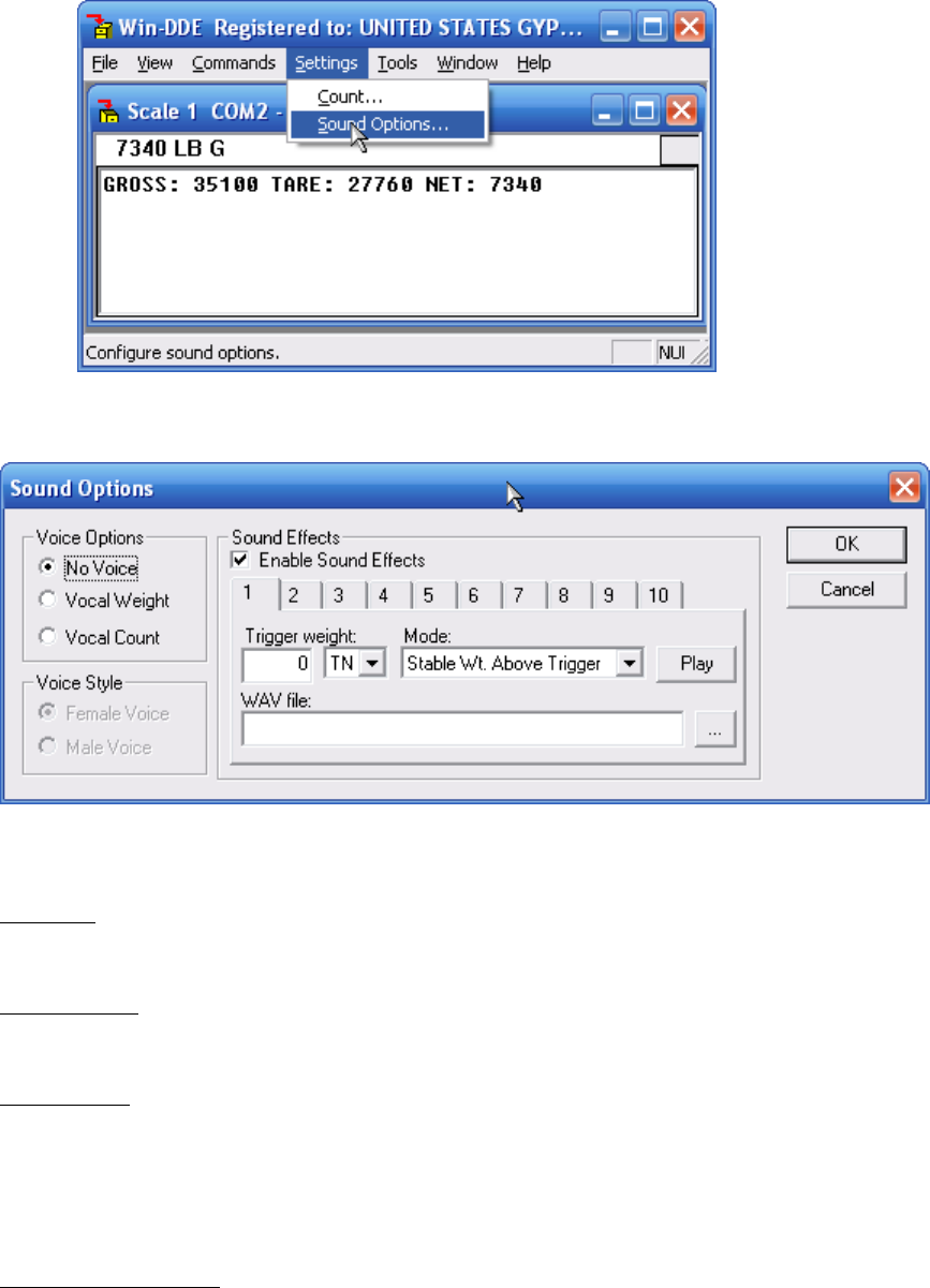
The “Settings” menu option provides a “Sound Options” selection.
15
Click “Sound Options…” to display the sound options dialog box.
Your computer must be equipped with a sound card and speakers for sound options to function.
No Voice
The DDE Server will not speak.
Vocal Weight
The DDE server will speak the weight.
Vocal Count
The DDE server will speak the count.
If either “Vocal Weight” or “Vocal Count” is specified an additional selection for “Female
Voice” or “Male Voice” is available.
Enable Sound Effects

16
The “Enable Sound Effects” check box should be checked to allow the The DDE Server will play
up to 10 sounds in the form of wav files. For example a particular wav file may play when a
weight of 24000 pounds is reached. Another wav file may play when a weight of 78000 pounds
of the scale capacity is reached.
Number tab
Use the “Number” tab to specify the sound to edit from “1” through “10”. The prompts which
follow will indicate the settings for the specified sound.
Trigger Weight
Specify the weight value for the sound to play. The trigger weights should be in order, so that
sound 1 is a lighter trigger weight, than sound 2.
Mode
The mode for each sound may be specified as “Stable Wt. Above Trigger”, “Weighing Up”, or
“Weighing Down”. Sounds specified as “Stable Wt. Above Trigger” will play only when the
weight is stable and above the trigger weight. If more than one sound fits the condition when the
weight stabilizes only sound with the highest trigger value is played. Sounds configured for
“Weighing Up” or “Weighing Down” will play when the weight passes the trigger weight either
weighing up or weighing down, as appropriate.
WAV File
The full path should be specified to the WAV file to play. The “…” button may be clicked to
browse to a WAV file. In Microsoft Windows XP for the list of sounds shown below navigate to
C:\Windows\Media
Play
The “Play” button may be clicked to hear the sound immediately.

17
Help
The “Help” menu option is used to access the “About box”.
Click “About…” to display an about box which will give the version of the DDE server.
The “http://www.cardinalscale.com” button may be clicked to open the Cardinal Scale main web
page if the computer has internet access.
Click the “OK” button to return to main Win-DDE screen.
File
The “File” menu option is used to access the “Exit” function.

18
Click “Exit” to close the DDE server or hide the server window.
Click “Yes” to exit the Win-DDE server, or click “No” to keep Win-DDE running, but hide the
server Window.
Click the Win-DDE icon in the system tray to show the server window when it is hidden.
Reading information from the server
Three pieces of data must be specified by a DDE client program before any information can be
obtained from a DDE server.
• Application or Service - This is generally the program name, "WINDDE".
• Topic - The default topic name for WinDDE indicator one is "SCALE".
• Item - Several different item names are provided. Refer to the chart below:
ITEM
TYPE
DESCRIPTION

19
STR
String
Weight string, for example, "40500 LB G MO."
WT
Number
(Double)
Numeric weight, for example, 40500.
STAT
String
“ “ – Normal weight, “OC” – Over Capacity, “BZ” – Below
Zero, “MO” – Motion, or “CZ” – Center-of-Zero.
INFO
String
Win-DDE server version string (similar to): “Win-DDE
Server Version 2.00 Compiled: Mar 13 2003 15:23:12”
OC
Number
(Boolean)
1 – Over Capacity, 0 – Not Over Capacity
BZ
Number
(Boolean)
1 – Below Zero, 0 – Zero or above
MO
Number
(Boolean)
1 – Motion, 0 – Stable weight
CZ
Number
(Boolean)
1 – Center-of-Zero, 0 – Not Center-of-Zero
UNITS
Number
(Integer)
0 – Short tons, 1 – Pounds, 2 – Kilograms, 3 – Metric tons,
4 – Long tons
MODE
Number
(Integer)
0 – Gross, 1 – Tare, 2 – Net
CNT
Number
(Integer)
The number of items on the scale
WT1
Number
(Double)
Platform 1 weight
WT2
Number
(Double)
Platform 2 weight
WT3
Number
(Double)
Platform 3 weight
NOTE: The following are examples of how to obtain DDE data in several
of the popular spreadsheet and database programs.
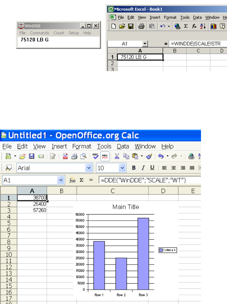
Microsoft Excel
To read the weight string into a Microsoft Excel spreadsheet cell enter the following:
=WINDDE|SCALE!STR
This will provide automatically updating data in the spreadsheet cell. To read the
numeric weight into the cell replace the "STR" with "WT." Using the numeric weight may
be useful for calculations or charts.
20
OpenOffice Calc
To read the weight value into a OpenOffice Calc cell enter the following:
=DDE("WinDDE";"SCALE";"WT")
This will provide automatically updating data in the spreadsheet cell.
21
You may create a chart based on the numeric cells. As the weight changes the value in
the cell and the chart display will automatically update.
Quattro Pro for Windows
To read the weight string into a Quattro Pro for Windows spreadsheet cell enter the
following:
@DDELINK([WINDDE|SCALE]"STR")
This will provide automatically updating data in the spreadsheet cell. To read the
numeric weight into the cell replace the "STR" with "WT."
Lotus 1-2-3 for Windows
For one time data access create a macro with the following commands. Make sure the
cell A1 is not in use.
{DDE-OPEN "WINDDE","SCALE"}
{DDE-REQUEST A1,"STR"}
{DDE-CLOSE}
Run the macro. It will insert the current weight string into the cell A1. Note, the data
will not update automatically.
For automatically updating data create three macros. Create the first macro starting at
cell A3.
{DDE-OPEN "WINDDE","SCALE"}
{DDE-ADVISE A9,"STR"}
This macro starts the communications. The second line sets the communications mode
to advise of changes in the data and run the macro at cell A9 when the data changes.
Create the second macro at cell A9.
{DDE-REQUEST A1,"STR"}
This macro is called automatically when the item, "STR", changes. The macro requests
the information from the server and places the data in cell A1. Create a third macro at
cell A12.
{DDE-CLOSE}
Run this macro to stop the communications.

22
Microsoft Access
A simple way to obtain DDE data in Microsoft Access is to create a form. Within the
form create a text display box. In the properties setting for the text box select the
"Control Source." Type the following:
=DDE("WINDDE", "SCALE", "STR")
This will make the weight string appear in the text box when the form is opened. This
method will only obtain the information when the form is opened. The display will not
update automatically. Access provides several commands that can be used for DDE
communications. You may create a button on a form to zero the scale. Create an
event procedure for the button as follows:
Sub Zero_Click ()
On Error Resume Next
Dim chl
chl = DDEInitiate("WINDDE", "SCALE")
DDEExecute chl, "Zero"
DDETerminate chl
End Sub
The Win-DDE Server responds to the "Zero" command by zeroing the indicator if it is in
zero range. The command, "Switch Lb/Kg" may also be sent to the server to switch
between pounds and kilograms.
Win-DDE Weight Indicator
A DDE client program “Win-DDE Weight Indicator” is provided with the “Win-DDE”
server. The program provides simple weight indicator functions on the computer. The
Win-DDE server may be used without running this program.
To start the “Start” button on the task bar. Select “Programs”, “WinDDE”, and click
“WinDDE Client Indicator.”
The weight indicator will appear.
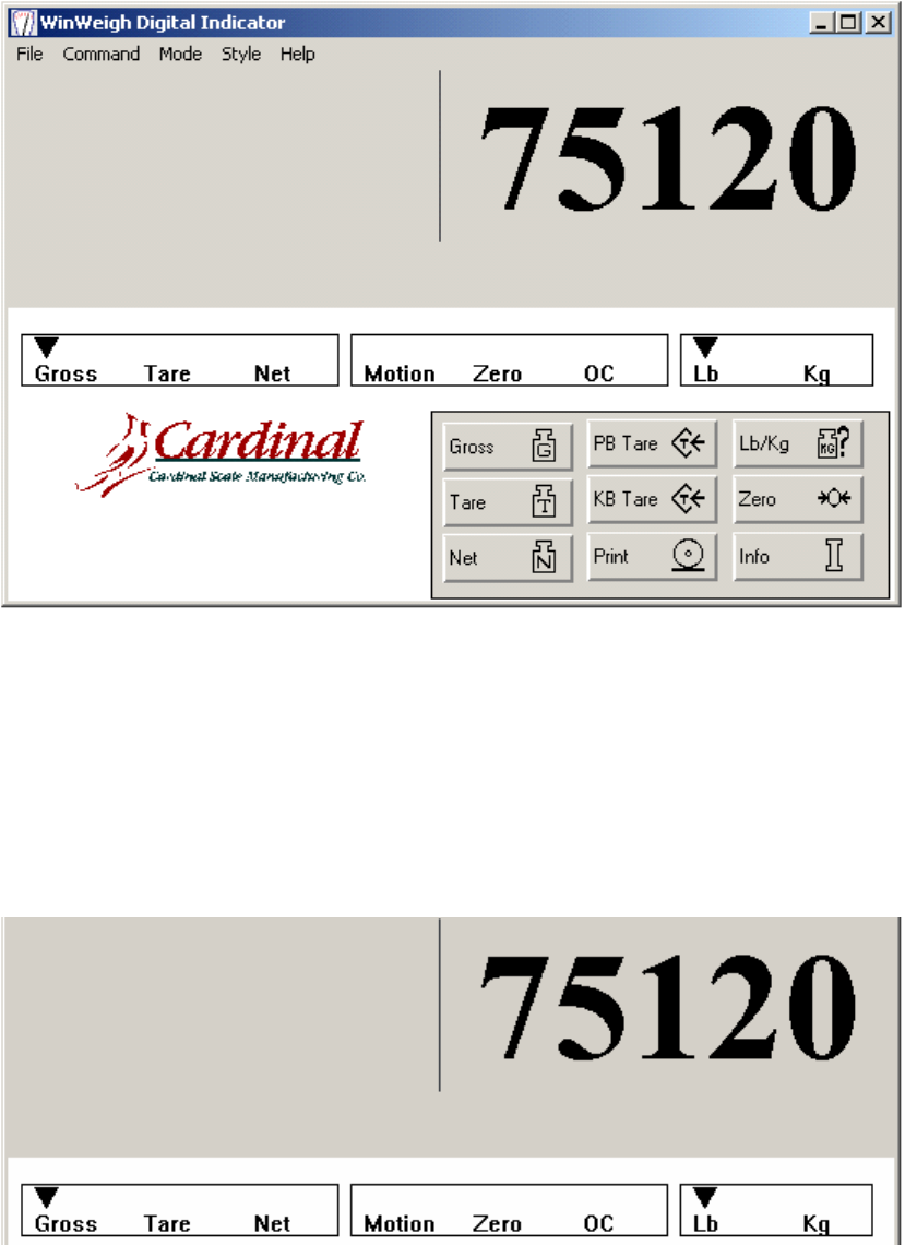
23
The display shows a menu bar across the top of the window. The weight display is
below the menu bar. Status indicators are placed below the weight display to show
various conditions. A keypad for general scale functions is at the bottom right side of
the window.
DISPLAY
This display shows the gross, tare, or net weight value.
STATUS INDICATORS
The status indicators show the condition of the indicator.

24
Gross, Tare, Net
An arrow points to the Gross, Tare, or Net label to show the mode the indicator is in.
Motion
An arrow is visible above the Motion label when the indicator is in motion.
Zero
An arrow is visible above the Zero label when the gross weight is at zero.
OC
An arrow is visible above the OC label when the indicator is over capacity.
Lb/Kg
An arrow points to Lb or Kg to show whether the indicator is displaying the weight in
pounds or kilograms.
KEYPAD
Gross
The Gross key places the indicator in Gross mode.
Tare
The Tare key places the indicator in Tare mode.
Net
The Net key places the indicator in Net mode.
PB Tare
The PB Tare key performs a Push-Button Tare function. When this key is clicked the
current scale weight will be placed in the Tare. The indicator will then be placed in Net
mode, showing zero net.
KB Tare

25
The KB TARE key perform a Keyboard Tare function. When this key is pressed an
additional display window appears.
A new tare weight may be keyed in. Click OK to resume normal operations. The
indicator will be placed in the Net mode.
Print
Pressing the Print key will cause a ticket to be printed using the default Windows
printer. If the indicator is in motion the display will show:
Click OK. When motion ceases, click the Print button again to print the ticket.
WinWeigh Digital Indicator
Cardinal Scale Mfg. Co.
Weight Ticket:
Date: 06/12/02 Time: 13:47
Gross: 75120
Tare: 10000
Net: 65120
LB/KG
Click the Lb/Kg key to switch between pounds and kilograms. Any existing tare weight
will be zeroed. The indicator will automatically switch to Gross mode.

26
Zero
Click the Zero key to zero the scale, if it is within the zero range.
Info
Click the Info key to provide a window with information about the software versions.
MENU BAR
A menu bar across the top of the indicator provides several functions.
FILE
Open - This command displays a standard windows file-open box to allow alternate
indicator configuration settings to be loaded into memory.
Save - This command saves any changes made to the configuration settings.
Save As - This command displays a standard windows file-save as box to allow
modified configuration settings to be saved with different names.
Print - This command performs the same function as the print command on the
keypad.
COMMAND

27
Push-Button Tare - This command performs the same function as the PB Tare
button on the keypad.
Keyboard Tare - This command performs the same function as the KB Tare button
on the keypad.
Lb/Kg - This command performs the same function as the Lb/Kg button on the
keypad.
Zero - This command performs the same function as the Zero button on the keypad.
Configuration - This command provides a display window to edit the configuration
settings. You may change the DDE application, topic, and items names to obtain
information from the server. The scale capacity, divisions, and decimal precision
may be set. The weight string information may also be configured to designate the
string positions and characters which represent the conditions, motion, zero, over
capacity, pounds, and kilograms.

28
MODE
Gross - This command performs the same function as the keypad Gross key.
Tare - This command performs the same function as the keypad Tare key.
Net - This command performs the same function as the keypad Net key.
STYLE
Font - This command displays a standard Windows font setting box to allow selection
of the display font for the weight display window.
Keypad On - This command causes the keypad and the lower half of the Indicator to
appear. See "Keypad Off." below.
Keypad Off - This command causes the keypad and the lower half of the display to
disappear. This is useful to reduce the display space required for the indicator.
HELP
About - This command performs the same function as the "Info" button on the
keypad.
Win-DDE Technical Information
The Win-DDE server communicates with DDE client applications using either XlTable
format or CF_TEXT format, as requested by the client. XlTable format is preferred
because it provides the fastest most efficient communication.
29
Win-DDE is written in Microsoft Visual C++ using the Microsoft Foundation Classes.
Win-DDE is a multi-threaded Win32 application providing high-performance.
Win-DDE uses Winsock 1.1 or 2.0 for TCP/IP communications.
Predefined Device Profile Information
205CAP – Permits print capture of gross, tare, and net weight.
205 Setup –
1. Press “*”. The display will show “Funct=”. Press “REVIEW”.
2. The display will show “PUO=” Press “ENTER”. The display will show “no”. Press
“ENTER.”
3. The display will show “SLEEP=”. Press “ENTER”. The display will show the sleep
value. Press “ENTER”.
4. The display will show “A off=”. Press “ENTER”. The display will show the auto-off
setting. Press “ENTER”.
5. The display will show “CLTar=” Press “ENTER”. The display will show the clear-tare
setting. Press “ENTER”.
6. The display will show “Sio?” Press “ENTER”. The display will show “no”. Press the “*”
key to change the display to “YES”. Press “ENTER”.
7. The display will show “bAUd=” Press “ENTER”. The display will show the current
baud rate setting. For the default 9600 baud press the “*” key until the display shows
“96”. Press “ENTER”.
8. The display will show “PrtY=” Press “ENTER”. The display will show the current parity
setting. For the default no paraity press the “*” key until the display shows “0”. Press
“ENTER”.
9. The display will show “BitS=” Press “ENTER”. The display will show the current data
bits setting. For the default eight data bits press the “*” key until the display shows “8”.
Press “ENTER”.
10. The display will show “StoP=” Press “ENTER”. The display will show the current
stop bits setting. For the default one stop bit press the “*” key until the display shows
“1”. Press “ENTER”.
11. The display will show “Cont1=” Press “ENTER”. The display will show the current
setting for continuous data for serial port one. For printer capture the indicator must not
be continuous. Press the “*” key until the display shows “no”. Press “ENTER”.
12. The display will show “Cont2=” Press “ENTER”. The display will show the current
setting for continuous data for serial port one. For printer capture the indicator must not
be continuous. Press the “*” key until the display shows “no”. Press “ENTER”.
13. The display will show “Print?”. Press “ENTER”. The display will show “no”. Press
the “*” key to change the display to “YES”. Press “ENTER”.
14. The display will show “Port=”. Press “ENTER”. The display will show the serial port
selected for printer output. Press the “*” key to set this to the correct port to be
connected to the computer. If only one serial port is wired from the 205 indicator this
would usually be “1”. Press “ENTER”.
30
15. The display will show “GroSS=”. Press “ENTER”. The display will show the current
tab setting for the gross weight. Press the “*” key to change the values and the “UNITS”
key to move the cursor as necessary until the display shows “3.01”. Press “ENTER”.
16. The display will show “tArE=”. Press “ENTER”. The display will show the current tab
setting for the tare weight. Press the “*” key to change the values and the “UNITS” key
to move the cursor as necessary until the display shows “4.01”. Press “ENTER”.
17. The display will show “nET=”. Press “ENTER”. The display will show the current tab
setting for the net weight. Press the “*” key to change the values and the “UNITS” key to
move the cursor as necessary until the display shows “5.01”. Press “ENTER”.
17. The display will show “G ACC=”. Press “ENTER”. The display will show the current
tab setting for the gross accumulator. Press the “*” key to change the values and the
“UNITS” key to move the cursor as necessary until the display shows “0.00”. Press
“ENTER”.
17. The display will show “n ACC=”. Press “ENTER”. The display will show the current
tab setting for the net accumulator. Press the “*” key to change the values and the
“UNITS” key to move the cursor as necessary until the display shows “0.00”. Press
“ENTER”.
17. The display will show “CrLF=”. Press “ENTER”. The display will show the current
setting for carriage return line feed. Press the “*” key to until the display shows “YES”.
Press “ENTER”.
17. The display will show “EoP=”. Press “ENTER”. The display will show the current
setting for end of print. Press the “*” key to until the display shows “0”. Press “ENTER”.
1. Press”*” and “PRINT” to set the print format. The display shows “Prt=”
2. Press “ENTER”. The display will show the current print format. Press “*” until this is
“0”. Press “ENTER”.
210CAP – Permits print capture of gross, tare, and net weight.
210 Setup –
1. Press “*”. The display will show “Funct=”. Press “REVIEW”.
2. The display will show “PUO=” Press “ENTER”. The display will show “no”. Press
“ENTER.”
2. The display will show “td=” Press “ENTER”. The display will show “12”. Press
“ENTER.”
2. The display will show “d oUt=” Press “ENTER”. The display will show “0”. Press
“ENTER.”
3. The display will show “SLEEP=”. Press “ENTER”. The display will show the sleep
value. Press “ENTER”.
4. The display will show “A off=”. Press “ENTER”. The display will show the auto-off
setting. Press “ENTER”.
5. The display will show “CLTar=” Press “ENTER”. The display will show the clear-tare
setting. Press “ENTER”.
31
6. The display will show “Sio?” Press “ENTER”. The display will show “no”. Press the
“1/YES” key to change the display to “YES”. Press “ENTER”.
7. The display will show “bAUd=” Press “ENTER”. The display will show the current
baud rate setting. For the default 9600 baud press the “9” and “6” key so that the
display shows “96”. Press “ENTER”.
8. The display will show “PrtY=” Press “ENTER”. The display will show the current parity
setting. For the default no parity press the “0” key so that the display shows “0”. Press
“ENTER”.
9. The display will show “BitS=” Press “ENTER”. The display will show the current data
bits setting. For the default eight data bits press the “8” key so that the display shows
“8”. Press “ENTER”.
10. The display will show “StoP=” Press “ENTER”. The display will show the current
stop bits setting. For the default one stop bit press the “1” key so that the display shows
“1”. Press “ENTER”.
11. The display will show “Cont1=” Press “ENTER”. The display will show the current
setting for continuous data for serial port one. For printer capture the indicator must not
be continuous. Press the “0/NO” key so that the display shows “no”. Press “ENTER”.
12. The display will show “Cont2=” Press “ENTER”. The display will show the current
setting for continuous data for serial port two. For printer capture the indicator must not
be continuous. Press the “0/NO” key so that the display shows “no”. Press “ENTER”.
13. The display will show “Print?”. Press “ENTER”. The display will show “no”. Press
the “1/YES” key to change the display to “YES”. Press “ENTER”.
14. The display will show “Port=”. Press “ENTER”. The display will show the serial port
selected for printer output. Press the “1” or “2” key to set this to the correct port to be
connected to the computer. If only one serial port is wired from the 210 indicator this
would usually be “1”. Press “ENTER”.
15. The display will show “HoUr=”. Press “ENTER”. The display will show the current
tab setting for the time. Press the “0” key to change the to “0.00” so that the time is not
provided in the output. Press “ENTER”.
15. The display will show “dAte=”. Press “ENTER”. The display will show the current tab
setting for the date. Press the “0” key to change the display to “0.00” so that the date is
not provided in the output. Press “ENTER”.
15. The display will show “CnC n=”. Press “ENTER”. The display will show the current
tab setting for the consecutive number. Press the “6”, “0”, and then the “1” key to
change the display to “6.01” so that the consecutive number is provided on the sixth line
of the output. Press “ENTER”.
15. The display will show “GroSS=”. Press “ENTER”. The display will show the current
tab setting for the gross weight. Press the “2”, “0”, and then the “1” key to change the
display to “2.01” so that the gross weight is provided on the second line of the output.
Press “ENTER”.
16. The display will show “tArE=”. Press “ENTER”. The display will show the current tab
setting for the tare weight. Press the “3”, “0”, and then the “1” key to change the display
to “3.01” so that the tare weight is provided on the third line of the output. Press
“ENTER”.
17. The display will show “nET=”. Press “ENTER”. The display will show the current tab
setting for the net weight. Press the “4”, “0”, and then the “1” key to change the display
32
to “4.01” so that the net weight is provided on the fourth line of the output. Press
“ENTER”.
17. The display will show “G ACC=”. Press “ENTER”. The display will show the current
tab setting for the gross accumulator. Press the “0” key to change display to “0.00” sot
that the gross weight accumulator is not provided on the output. Press “ENTER”.
17. The display will show “n ACC=”. Press “ENTER”. The display will show the current
tab setting for the net accumulator. Press the “0” key to change the display to “0.00” so
the net weight accumulator is not provided on the output. Press “ENTER”.
17. The display will show “CoUnt=”. Press “ENTER”. The display will show the current
tab setting for the count. Press the “0” key to change the display to “0.00” so the count
is not provided on the output. Press “ENTER”.
17. The display will show “EACH=”. Press “ENTER”. The display will show the current
tab setting for the each. Press the “0” key to change the display to “0.00” so the each
value is not provided on the output. Press “ENTER”.
17. The display will show “CrLF=”. Press “ENTER”. The display will show the current
setting for carriage return line feed. Press the “1/YES” key so that the display shows
“YES”. Press “ENTER”.
17. The display will show “EoP=”. Press “ENTER”. The display will show the current
setting for end of print. Press the “0” key so that the display shows “0”. Press “ENTER”.
1. Press”*” and “PRINT” to set the print format. The display shows “Prt=”
2. Press “ENTER”. The display will show the current print format. Press the “0” key so
that the display shows “0”. Press “ENTER”.
738_CAP – Permits print capture of ID, Time/Date, CN, gross, tare, and net weight.
738 Setup –
S2=10000000
Tabs t = 0-10
Tabs d= 0-1
Tabs id= 1-0
Tabs Cn= 2-0
Tabs G= 3-0
Tabs TA=4-0
Tabs n= 5-0
You can test this with the 738 by storing a keyboard tare "*" TARE type a value such as 100 and press
enter. You must have at least that much weight on the scale. Then press "*" NET print, to print the gross,
tare, net ticket. WinDDE will catch the ticket fields and put them into excel.

33
How to get GROSS TARE NET from the 210 to WinDDE
To get the output shown below the indicator tabs must be set correctly as well as some additional setup in WinDDE.
The additional setup in WinDDE is not extensive, it is only a slight modification to the 210_CAP profile.
If a profile named 210_PRINT does not exist it will need to be created, otherwise just choose the 210_PRINT. To
create the 210_PRINT profile, choose the 210_CAP profile and click the edit button beside it. An Indicator Profile
window will popup. There are only a couple of changes that need to be made here.
1) Change the ID from 210_CAP to 210_PRINT (changing the name creates a new profile)
2) In the Print Capture section there are several tabs shown.
Tabs 4, 5, & 6 need to be changed to have a Flag of 0 and DDE Item should be blank.
3) Click OK

34
Depending on the version of WinDDE, the Setup Indicators window should look similar to the screenshot below.
Choose the correct Device Port and ensure that the communications setting are correct and press OK.
210PRINT – Permits print capture of gross, tare, and net weight.
210 Setup –
1. Press “*”. The display will show “Funct=”. Press “REVIEW”.
2. The display will show “PUO=” Press “ENTER”. The display will show “no”. Press “ENTER.”
2. The display will show “td=” Press “ENTER”. The display will show “12”. Press “ENTER.”
2. The display will show “d oUt=” Press “ENTER”. The display will show “0”. Press “ENTER.”
3. The display will show “SLEEP=”. Press “ENTER”. The display will show the sleep value. Press
“ENTER”.
4. The display will show “A off=”. Press “ENTER”. The display will show the auto-off setting. Press
“ENTER”.
5. The display will show “CLTar=” Press “ENTER”. The display will show the clear-tare setting. Press
“ENTER”.
6. The display will show “Sio?” Press “ENTER”. The display will show “no”. Press the “1/YES” key to
change the display to “YES”. Press “ENTER”.
7. The display will show “bAUd=” Press “ENTER”. The display will show the current baud rate setting. For
the default 9600 baud press the “9” and “6” key so that the display shows “96”. Press “ENTER”.
8. The display will show “PrtY=” Press “ENTER”. The display will show the current parity setting. For the
default no parity press the “0” key so that the display shows “0”. Press “ENTER”.
9. The display will show “BitS=” Press “ENTER”. The display will show the current data bits setting. For the
default eight data bits press the “8” key so that the display shows “8”. Press “ENTER”.
10. The display will show “StoP=” Press “ENTER”. The display will show the current stop bits setting. For
the default one stop bit press the “1” key so that the display shows “1”. Press “ENTER”.
11. The display will show “Cont1=” Press “ENTER”. The display will show the current setting for
continuous data for serial port one. For printer capture the indicator must not be continuous. Press the
“0/NO” key so that the display shows “no”. Press “ENTER”.
35
12. The display will show “Cont2=” Press “ENTER”. The display will show the current setting for
continuous data for serial port two. For printer capture the indicator must not be continuous. Press the
“0/NO” key so that the display shows “no”. Press “ENTER”.
13. The display will show “Print?”. Press “ENTER”. The display will show “no”. Press the “1/YES” key to
change the display to “YES”. Press “ENTER”.
14. The display will show “Port=”. Press “ENTER”. The display will show the serial port selected for printer
output. Press the “1” or “2” key to set this to the correct port to be connected to the computer. If only one
serial port is wired from the 210 indicator this would usually be “1”. Press “ENTER”.
16. The display will show “HoUr=”. Press “ENTER”. The display will show the current tab setting for the
time. Press the “0” key to change the to “0.00” so that the time is not provided in the output. Press
“ENTER”.
17. The display will show “dAte=”. Press “ENTER”. The display will show the current tab setting for the
date. Press the “0” key to change the display to “0.00” so that the date is not provided in the output. Press
“ENTER”.
18. The display will show “CnC n=”. Press “ENTER”. The display will show the current tab setting for the
consecutive number. Press the “0” key to change the display to “0.00” so that the consecutive number is
provided on the sixth line of the output. Press “ENTER”.
19. The display will show “GroSS=”. Press “ENTER”. The display will show the current tab setting for the
gross weight. Press the “2”, “0”, and then the “1” key to change the display to “2.01” so that the gross
weight is provided on the second line of the output. Press “ENTER”.
20. The display will show “tArE=”. Press “ENTER”. The display will show the current tab setting for the tare
weight. Press the “3”, “0”, and then the “1” key to change the display to “3.01” so that the tare weight is
provided on the third line of the output. Press “ENTER”.
21. The display will show “nET=”. Press “ENTER”. The display will show the current tab setting for the net
weight. Press the “4”, “0”, and then the “1” key to change the display to “4.01” so that the net weight is
provided on the fourth line of the output. Press “ENTER”.
22. The display will show “G ACC=”. Press “ENTER”. The display will show the current tab setting for the
gross accumulator. Press the “0” key to change display to “0.00” sot that the gross weight accumulator is
not provided on the output. Press “ENTER”.
23. The display will show “n ACC=”. Press “ENTER”. The display will show the current tab setting for the
net accumulator. Press the “0” key to change the display to “0.00” so the net weight accumulator is not
provided on the output. Press “ENTER”.
24. The display will show “CoUnt=”. Press “ENTER”. The display will show the current tab setting for the
count. Press the “0” key to change the display to “0.00” so the count is not provided on the output. Press
“ENTER”.
25. The display will show “EACH=”. Press “ENTER”. The display will show the current tab setting for the
each. Press the “0” key to change the display to “0.00” so the each value is not provided on the output.
Press “ENTER”.
26. The display will show “CrLF=”. Press “ENTER”. The display will show the current setting for carriage
return line feed. Press the “1/YES” key so that the display shows “YES”. Press “ENTER”.
27. The display will show “EoP=”. Press “ENTER”. The display will show the current setting for end of
print. Press the “0” key so that the display shows “0”. Press “ENTER”.
