OPERATING MANUAL

SAFETY PRECAUTIONS
CAUTION
RISK OF ELECTRIC SHOCK DO NOT OPEN
CAUTION: TO REDUCE THE RISK OF ELECTRIC SHOCK, DO NOT REMOVE COVER (OR BACK). NO USER-SERVICEABLE PARTS INSIDE. REFER
SERVICING TO QUALIFIED SERVICE PERSONNEL
THE LIGHTNING FLASH WITH ARROWHEAD SYMBOL WITHIN AN
EQUILATERAL TRIANGLE IS INTENDED TO ALERT THE USER TO
THE PRESENCE OF UNINSULATED “DANGEROUS VOLTAGE”
WITHIN THE PRODUCT’S ENCLOSURE THAT MAY BE OF
SUFFICIENT MAGNITUDE TO CONSTITUTE A RISK OF ELECTRIC
SHOCK TO PERSONS.
THE EXLAMATION POINT WITHIN AN EQUILATERAL TRIANGLE IS
INTENDED TO ALERT THE USER TO THE PRESENCE OF
IMPORTANT OPERATING AND MAINTENANCE (SERVICING)
INSTRUCTIONS IN THE LITERATURE ACCOMPANYING THE
APPLIANCE.
WARNING: TO REDUCE THE RISK OF FIRE OR ELECTRIC SHOCK, DO
NOT EXPOSE THIS APPARATUS TO RAIN OR MOISTURE, AND OBJECTS
FILLED WITH LIQUIDS, SUCH AS VASES, SHOULD NOT BE PLACED ON
THIS APPARATUS.
CAUTION: FOR CONTINUED PROTECTION AGAINST RISK OF FIRE,
REPLACE THE FUSE ONLY WITH THE SAME AMPERAGE AND
VOLTAGE TYPE. REFER REPLACEMENT TO QUALIFIED SERVICE
PERSONNEL.
CAUTION: TO PREVENT ELECTRIC SHOCK, MATCH WIDE BLADE OF
PLUG TO WIDE SLOT, FULLY INSERT.
WARNING: UNIT MAY BECOME HOT. ALWAYS PROVIDE
ADEQUATE VENTILATION TO ALLOW FOR COOLING. DO NOT
PLACE NEAR A HEAT SOURCE, OR IN SPACES THAT CAN RESTRICT
VENTILATION.
IMPORTANT SAFETY INSTRUCTIONS:
Read these instructions.
Keep these instructions.
Heed all warnings.
Follow all instructions.
Do not use this apparatus near water.
Clean only with a dry cloth.
Do not block any of the ventilation openings. Install in
accordance with the manufacturer’s instructions.
Do not install near any heat sources such as radiators, heat
registers, stoves or other apparatus (including amplifiers) that
produce heat.
Do not defeat the safety purpose of the polarized or grounding-
type plug. A polarized plug has two blades with one wider than
the other. A grounding-type plug has two blades and a third
grounding prong. The wide blade or the third prong is provided
for your safety. When the provided plug does not fit into your
outlet, consult an electrician for replacement of the obsolete
outlet.
Protect the power cord from being walked on or pinched,
particularly at plugs, convenience receptacles and the point where
they exit from the apparatus.
Only use the attachments/accessories specified by the
manufacturer.
Use only with a cart, stand, tripod, bracket or table specified by
the manufacturer, or sold with the apparatus.
When a cart is used, use caution when moving the cart/ apparatus
combination to avoid injury from tip-over.
Unplug this apparatus during lightning storms or when unused
for long periods of time.
Refer all servicing to qualified service personnel. Servicing is
required when the apparatus has been damaged in any way, such
as power supply cord or plug is damaged, liquid has been spilled
or objects have fallen into the apparatus, the apparatus has been
exposed to rain or moisture, does not operate normally, or has
been dropped.
1.
2.
3.
4.
5.
6.
7.
8.
9.
10.
11.
12.
13.
14.
15.
WARRANTY:
To reduce the risk of fire or electric shock, do not expose this apparatus to rain or moisture. Avoid installing this unit where foreign
objects may fall onto this unit and/or this unit may be exposed to liquid dripping or splashing. On the top of this unit, do not place:
Burning objects (i.e. candles), as they may cause fire, damage to this unit, and/or personal injury.
Containers with liquid in them, as they may fall and liquid may cause electrical shock to the user and/or damage to this unit.
Apparatus shall not be exposed to dripping or splashing and no objects filled with liquids, such as vases, shall be placed on the
apparatus.
Do not install this equipment in a confined space such as a case or similar. Install it away from direct sunlight, heat sources, vibration,
dust, moisture, and/or cold.
Do not cover this unit with a newspaper, tablecloth, curtain, etc. in order not to obstruct heat radiation. If the temperature inside this
unit rises, it may cause fire, damage to this unit, and/or personal injury.
Install this unit near the AC outlet and where the AC power plug can be reached easily.
This unit is not disconnected from the AC power source when it is turned off. This state is called the standby mode. In this state, this unit
is designed to consume a very small quantity of power.
NOTE:
This product is not an auto voltage Amplifier. Connect only to the prescribed AC outlet, i.e., 120V 60Hz or 240V 50/60Hz.
CAUTION:
Top surface can become hot.
CAUTION:
These servicing instructions are for use by qualified service personnel only. To reduce the risk of electric shock, do not perform any
servicing other than that contained in the operating instructions, unless you are qualified to do so.
CAUTION:
Changes or modifications to this equipment not expressly approved by Paradigm Electronics for compliance could void the user’s
authority to operate this equipment.
FCC WARNING:
Changes or modifications not expressly approved by the party responsible for compliance could void the user’s authority to operate the
equipment.
This equipment has been tested and found to comply with the limits for a class B digital device, pursuant to part 15 of the FCC Rules.
These limits are designed to provide reasonable protection against harmful interference in a residential installation. This equipment
generates, uses and can radiate radio frequency energy and, if not installed and used in accordance with the instructions, may cause
harmful interference to radio communications. However, there is no guarantee that interference will not occur in a particular installation.
If this equipment does cause harmful interference to radio or television reception, which can be determined by turning the equipment
off and on, the user is encouraged to try to correct the interference by one or more of the following measures:
Reorient or relocate the receiving antenna.
Increase the separation between the equipment and amplifier.
Connect the equipment into an outlet on a circuit different from that to which the amplifier is connected.
Consult the dealer or an experienced radio / TV technician for help.
•
•
•
•
•
•

IMPORTANT INFORMATION FOR UK CUSTOMERS:
DO NOT cut off the mains plug from this equipment. If the plug fitted is not suitable for the power points in your home or the cable is
too short to reach a power point, then obtain an appropriate safety approved extension lead or consult your dealer. If, nonetheless, the
mains plug is cut off, REMOVE THE FUSE and dispose of the PLUG immediately, to avoid possible shock hazard by inadvertent connection
to the mains supply. If this product is not provided with a mains plug, or one has to be fitted, then follow the instructions given below:
IMPORTANT: DO NOT make any connection to the larger terminal which is marked with the letter “E” or by the safety earth
symbol or colored GREEN or GREEN AND YELLOW.
The wires in the mains lead on this product are colored in accordance with the following code:
BLUE – NEUTRAL
BROWN – LIVE
As these colors may not correspond with the colored markings identifying the terminals in your plug, proceed as follows:
The BLUE wire must be connected to the terminal marked with the letter “N” or colored BLACK.
The BROWN wire must be connected to the terminal marked with the letter “L” or colored RED.
When replacing the fuse, only a correctly rated and approved type should be used, and be sure to re-fit the fuse cover. If in doubt consult
a competent electrician.
NOTES ON ENVIRONMENTAL PROTECTION:
At the end of its useful life, this product must not be disposed of with regular household waste but must be returned to a collection
point for the recycling of electrical and electronic equipment. The symbol on the product, user’s manual and packaging, point this out.
The materials can be reused in accordance with their markings. Through re-use, recycling of raw materials or other forms of recycling of
old products, you are making an important contribution to the protection of our environment. Your local administrative office can advise
you of the responsible waste disposal point.
RECYCLING AND REUSE GUIDELINES (Europe):
In accordance with the European Union WEEE (Waste Electrical and Electronic Equipment) directive effective August 13, 2005, we would
like to notify you that this product may contain regulated materials which, upon disposal, require special reuse and recycling processing.
For this reason Paradigm Electronics Inc. (the manufacturer of Paradigm speakers and Anthem electronic products) has arranged with its
distributors in European Union member nations to collect and recycle this product at no cost to you. To find your local distributor please
contact the dealer from whom you purchased this product or go to our website at www.paradigm.com.
Please note that only the product falls under the WEEE directive. When disposing of packaging and other shipping material we
encourage you to recycle through the normal channels.
INFORMATION ABOUT COLLECTION AND DISPOSAL OF WASTE BATTERIES (DIRECTIVE 2006/66/EC OF THE
EUROPEAN PARLIAMENT AND THE COUNCIL OF EUROPEAN UNION)
(for European customers only)
Batteries bearing any of these symbols indicate that they should be treated as “separate collection” and not as municipal waste. It is
encouraged that necessary measures are implemented to maximize the separate collection of waste batteries and to minimize the
disposal of batteries as mixed municipal waste. End-users are exhorted not to dispose waste batteries as unsorted municipal waste. In
order to achieve a high level of recycling waste batteries, discard waste batteries separately and properly through an accessible collection
point in your vicinity. For more information about collection and recycling of waste batteries, please contact your local municipality,
your waste disposal service or the point of sale where you purchased the items.
By ensuring compliance and conformance to proper disposal of waste batteries, potential hazardous effects on human health is
prevented and the negative impact of batteries and waste batteries on the environment is minimized, thus contributing to the
protection, preservation and quality improvement of the environment.
Anthem and any related party assume no liability for the user’s failure to comply with any requirements.
TRADEMARKS
Anthem and any related party assume no liability for the user’s failure to comply with any requirements.
Anthem, AnthemLogic, ARC, Sonic Frontiers, and Paradigm are trademarks or registered trademarks of Paradigm Electronics Inc. ©
Paradigm Electronics Inc. All rights reserved. The information contained herein may not be reproduced in whole or in part without our
express written permission. We reserve the right to change specifications or features without notice as design improvements are
incorporated. Apple, AirPlay and the AirPlay logo, iPod, iPhone, and iPad are trademarks of Apple Inc., registered in the U.S. and other
countries.
AirPlay 2 works with iPhone, iPad, and iPod touch with iOS 11.4 or later, Mac with OS X Mountain Lion or later, and PC with iTunes 10.2.2
or later.
Manufactured under license from Dolby Laboratories. Dolby, Dolby Atmos, Pro Logic, and the double-D symbol are trademarks of Dolby
Laboratories.
Manufactured under license from IMAX Corporation. IMAX® is a registered trademark of IMAX Corporation in the United States and/or
other countries. For DTS patents, see http://patents.dts.com. Manufactured under license from DTS Licensing Limited. DTS, the Symbol,
DTS and the Symbol together are registered trademarks or trademarks of DTS, Inc. in the United States and/or other countries. © DTS,
Inc. All Rights Reserved.
For DTS patents, see http://patents.dts.com. Manufactured under license from DTS Licensing Limited. DTS, the Symbol, DTS in
combination with the symbol, DTS:X and the DTS:X logo are registered trademarks or trademarks of DTS, Inc. in the United States and/or
other countries. © DTS, Inc. All Rights Reserved.
For DTS patents, see http://patents.dts.com. Manufactured under license from DTS Licensing Limited. DTS, the Symbol, DTS and the
symbol together, Virtual:X and the DTS Virtual:X logo are registered trademarks and/or trademarks of DTS, Inc. in the United States and/
or other countries. © DTS, Inc. All Rights Reserved.
Google, Google Play, Chromecast, and other related marks are trademarks of Google LLC.
HDMI, the HDMI logo and High-Definition Multimedia Interface are trademarks or registered trademarks of HDMI Licensing LLC.
The Spotify Software is subject to third party licenses found here: www.spotify.com/ connect/third-party-licenses
Wi-Fi® is a registered trademark of the Wi-Fi Alliance. The Wi-Fi CERTIFIED Logo is a certification mark of the Wi-Fi Alliance.
All other trademarks are the property of their respective owners.

TABLE OF CONTENTS
1.0 BOX CONTENTS & PACKAGING
1.1 Before Making Connections
2.0 INTRODUCTION
2.1 In-Use Notices
2.2 Default Inputs
2.3 Front Panel
2.4 MRX 1140 Rear Panel
2.5 MRX 740 Rear Panel
2.6 MRX 540 Rear Panel
2.7 AVM 90 Rear Panel
2.8 AVM 70 Rear Panel
2.9 Remote Control
3.0 SPEAKER POSITIONING
3.1 Speakers
3.2 5.1-Channel Speaker Positioning
3.3 7.1-Channel Speaker Positioning
3.4 Height Effects Speaker Positioning
4.0 CONNECTIONS
4.1 HDMI Video Inputs And Outputs
4.3 Local Area Network
4.4 12 Volt Trigger
4.5 Infrared
4.6 RS-232
4.7 Power
4.8 Headphone Jack (Front Panel)
5.0 SETUP
5.1 Speaker Setup
5.2 Bass Management
5.3 Listener Position
5.4 Level Calibration
5.5 Input Setup
5.6 Preferences
5.7 Network / Control
5.8 Store / Load / Update
5.9 System Info
6.0 ANTHEM ROOM CORRECTION
6.1 Anthem Room Correction (ARC®)
6.2 Using ARC With An MRX/AVM
7.0 OPERATION
7.1 Power On / Off and Volume
7.2 Zone 2 Operation

1.0 BOX CONTENTS & PACKAGING
1.1 BEFORE MAKING CONNECTIONS
Check that you have received all items listed below and report discrepancies to your dealer as soon as possible. In case the unit
needs to be transported in the future, keep the packing materials. Retain the invoice that you received from your authorized
Anthem dealer at time of purchase – without it, service will not be provided under warranty.
AVM Processor or MRX Receiver
Remote Control
2x Wireless Network Antennas
2x AAA Batteries (included with 120V Models ONLY)
IEC Power Cord (US / UK / EU / CN types are supplied by factory, other types are normally provided by the local distributor)
Additional items in Anthem Room Correction (ARC) kit:
USB Microphone
Microphone Clip
Telescopic Stand with Boom
USB Cable
Save the Packaging
Save your MRX/AVM’s packaging. Should you move or should your unit require service, the original packaging will minimize the
risk of damage during transport.
•
•
•
•
•
•
•
•
•

2.0 INTRODUCTION
2.1 IN-USE NOTICES
Disconnect the power cord before connecting or disconnecting any components.
If the MRX/AVM was transported or stored in the cold, let it reach room temperature before use.
Due to continuing advances, operational characteristics may change. If this manual contains discrepancies, please check
www.AnthemAV.com for the latest manual or software.
2.2 DEFAULT INPUTS
Source Audio Input Video Input
HDMI 1 HDMI HDMI 1
HDMI 2 HDMI HDMI 2
HDMI 3 HDMI HDMI 3
HDMI 4 HDMI HDMI 4
HDMI 5 HDMI HDMI 5
HDMI 6 HDMI HDMI 6
HDMI 7 HDMI HDMI 7
eARC HDMI eARC None
Streaming Streaming None
Bluetooth Bluetooth None
Optical 1 Optical 1 None
Coax 1 Coax 1 None
Analog 1 Analog 1 None
The unit comes programmed from the factory with thirteen (fourteen on AVM) inputs, but you may change this to create up to 30
inputs. MRX/AVM uses virtual inputs that give you complete control of the name of each input you create, along with which video
(HDMI) input to use, which audio input (HDMI, digital, analog or streaming) to use, which speaker profile to use, and much more.
You can even create multiple inputs for the same source device. For example, a Blu-ray input configured for 7.1.4-channels and
another Blu-ray input configured for 2-channels (and no subwoofer). For information on setting up inputs, refer to the Setup
section of this manual.
•
•
•

2.3 FRONT PANEL
MRX 1140 model shown.
Display
Remote control sensor location
Volume control and menu navigation
Headphone jack
Power / standby
Mute
Next input or item
Previous input or item
Selection confirmation
Setup menu access
1.
2.
3.
4.
5.
6.
7.
8.
9.
10.

2.4 MRX 1140 REAR PANEL
US model shown. EU model is similar.
Wireless antenna connectors
USB jack for factory service
Local area network connection for IP control and Anthem Room Correction
HDMI outputs: HDMI 1 supports eARC (Enhanced Audio Return Channel)
HDMI inputs
AC input
RS-232 interface (bidirectional) for serial control
IR input and trigger outputs
Coaxial digital audio inputs
Optical digital audio inputs and output
Speaker connections
Analog audio inputs
Pre-out connections
Chassis ground screw
1.
2.
3.
4.
5.
6.
7.
8.
9.
10.
11.
12.
13.
14.

2.5 MRX 740 REAR PANEL
US model shown. EU model is similar.
Wireless antenna connectors
USB jack for factory service
Local area network connection for IP control and Anthem Room Correction
HDMI outputs: HDMI 1 supports eARC (Enhanced Audio Return Channel)
HDMI inputs
AC input
RS-232 interface (bidirectional) for serial control
IR input and trigger outputs
Coaxial digital audio inputs
Optical digital audio inputs and output
Speaker connections
Analog audio inputs
Pre-out connections
Chassis ground screw
1.
2.
3.
4.
5.
6.
7.
8.
9.
10.
11.
12.
13.
14.

2.6 MRX 540 REAR PANEL
US model shown. EU model is similar.
Wireless antenna connectors
USB jack for factory service
Local area network connection for IP control and Anthem Room Correction
HDMI outputs: HDMI 1 supports eARC (Enhanced Audio Return Channel)
HDMI inputs
AC input
RS-232 interface (bidirectional) for serial control
IR input and trigger outputs
Coaxial digital audio inputs
Optical digital audio inputs and output
Speaker connections
Analog audio inputs
Pre-out connections
Chassis ground screw
1.
2.
3.
4.
5.
6.
7.
8.
9.
10.
11.
12.
13.
14.

2.7 AVM 90 REAR PANEL
US model shown. EU model is similar.
Wireless antenna connectors
USB jack for factory service
Local area network connection for IP control and Anthem Room Correction
HDMI outputs: HDMI 1 supports eARC (Enhanced Audio Return Channel)
HDMI inputs
AC input
RS-232 interface (bidirectional) for serial control
IR input and trigger outputs
Coaxial digital audio inputs
Optical digital audio inputs and output
Pre-out connections (XLR)
Analog audio inputs
Chassis ground screw
Pre-out connections (RCA)
1.
2.
3.
4.
5.
6.
7.
8.
9.
10.
11.
12.
13.
14.

2.8 AVM 70 REAR PANEL
US model shown. EU model is similar.
Wireless antenna connectors
USB jack for factory service
Local area network connection for IP control and Anthem Room Correction
HDMI outputs: HDMI 1 supports eARC (Enhanced Audio Return Channel)
HDMI inputs
AC input
RS-232 interface (bidirectional) for serial control
IR input and trigger outputs
Coaxial digital audio inputs
Optical digital audio inputs and output
Pre-out connections (XLR)
Analog audio inputs
Chassis ground screw
Pre-out connections (RCA)
1.
2.
3.
4.
5.
6.
7.
8.
9.
10.
11.
12.
13.
14.
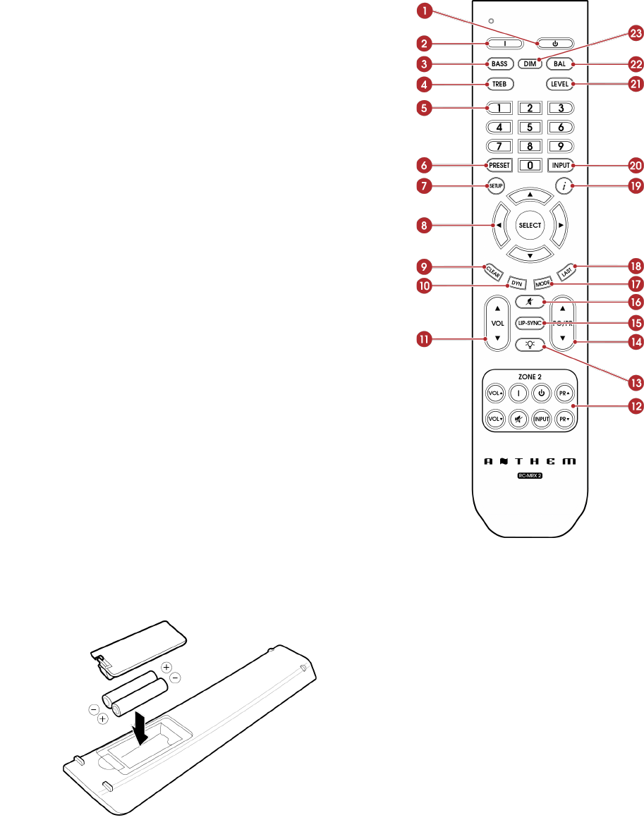
2.9 REMOTE CONTROL
Standby
Main zone power on
Bass
Treble
Numeric keypad
Preset
Setup menu
Navigation controls
Clear for deleting input configurations and
clearing new entry
Dolby Volume and Dolby Digital Dynamics
Volume
Zone 2 Controls
Backlight
PG/PR (DTS:X Dialog Level Control)
Lip-sync
Mute
Surround mode toggle
Last
Info display (front panel)
Input Select
Level
Balance L/R
Dim
The left/right buttons also select previous/next
input. The up/down buttons also control tuner
station.
Packing List:
Install batteries in the MRX/AVM remote control in the directions shown in the illustration below.
1.
2.
3.
4.
5.
6.
7.
8.
9.
10.
11.
12.
13.
14.
15.
16.
17.
18.
19.
20.
21.
22.
23.

Remote Control Range of Operation:
The MRX/AVM remote control operates best when used within the range and distance shown in the illustration below.
Rear and Front IR Inputs:
If your remote control is not working and you have already checked the batteries, before contacting technical support, check that
Front IR is set to “On” in the Network / Control menu.

3.0 SPEAKER POSITIONING
3.1 SPEAKERS
Your MRX/AVM, depending on the model, allows connection of anywhere from 2-channels (front left and right speakers with no
subwoofer) to 9.4.6-channels (a nine- speaker surround sound system with four subwoofers and six height speakers). When
setting up your speakers, care should be taken to achieve the best possible immersive audio experience.
Front Left & Right
The front speakers are what you hear when listening to 2 channel recordings but also play a large part in your home theater
setup along with the centre channel playing the majority of content. If using listening to music without a subwoofer it is advised to
use full range front speakers.
Center
The center channel is the most important speaker in a home theater system, as the center channel reproduces almost all of the
dialogue and a large portion of the front speaker information. The center channel speaker must be accurate, recommended for
use as a center speaker, and mate well with the front speakers. The center channel is not the place to cut corners.
Surround Left & Right / Back Left & Right
Surround and back speakers reproduce the information that makes sounds wrap around your home theater space.
Subwoofer(s)
With any surround sound system, you will need one or more high-quality subwoofers (the .1 in 5.1- or 7.1.4-channel surround
systems). Most movie soundtracks contain large amounts of bass information as part of the LFE (Low Frequency Effect) track that
sends information directly to your subwoofer. Good subwoofers will provide a foundation for the rest of the system and add
“weight” to music.
Height 1 and Height 2
Up to six height speakers (the .2 and .4 in 5.1.2- and 7.1.4-channel surround systems) can be connected to allow 3-dimensional
Dolby Atmos and DTS:X surround sound. Height speakers reproduce the information that makes it sound as if planes are flying
over your head and other similar effects.

3.2 5.1-CHANNEL SPEAKER POSITIONING
These illustrations show recommended speaker placements for a 5.1 channel system.
5.1.2 Configuration
with one pair in-ceiling height speakers
5.1.2 Configuration
with Dolby enabled front speakers
5.1.4 Configuration
with two pair in-ceiling height speakers
5.1.4 Configuration
with Dolby enabled front and surround speakers

3.3 7.1-CHANNEL SPEAKER POSITIONING
These illustrations show recommended speaker placements for a 7.1 channel system. (not all setups are available on the 540
due to number of channels available.
7.1.2 Configuration
with one pair in-ceiling height speakers
7.1.2 Configuration
with Dolby enabled front speakers
7.1.4 Configuration
with two pair in-ceiling height speakers
7.1.4 Configuration
with Dolby enabled front and rear speakers

3.4 HEIGHT EFFECTS SPEAKER POSITIONING
These illustrations show recommended speaker placements when using height effects channels.
One pair in-ceiling height speakers (side view)
Two pair in-ceiling height speakers (side view)

4.0 CONNECTIONS
4.1 HDMI VIDEO INPUTS AND OUTPUTS
An HDMI connection carries video and audio together. Connect HDMI output from MRX to a display with HDMI input – one with
the appropriate version of High-bandwidth Digital Content Protection (HDCP) is required to display copy-protected material.
Insert HDMI cables gently because the connector is more delicate than traditional ones. Damaged cables can damage jacks, and
the warranty does not cover jack replacement. Therefore, replacing HDMI cables is recommended if there is any chance of
damage with the existing cable.
Use only certified High-Speed cables and connecting devices. Cables and connecting devices that worked in an older setup do
not necessarily work with newer video formats such as Deep Color, UHD, or high frame rates. If you are using adapters or port
savers, start troubleshooting by eliminating them since they can affect bandwidth.
4.2 AUDIO CONNECTIONS
HDMI Audio Inputs and Outputs
Digital audio sources can be connected using an HDMI, coaxial, or optical cable. These connections carry linear PCM, and
bitstream (Dolby Digital, and DTS audio formats).
An HDMI connection is generally preferred to ensure the use of lossless audio when sources provide it, although you can also
use optical/coax connections for sources outputting 2-channel PCM, Dolby Digital 5.1, and DTS 5.1 without affecting audio
quality. HDMI outputs restrict audio to 2-channel PCM since these outputs are intended to connect to a television.
HDMI Enhanced Audio Return Channel
If your television provides audio through HDMI eARC (Enhanced Audio Return Channel), for example, when it accesses streaming
media sources, it can send the audio to the MRX/AVM’s HDMI output 1 (eARC), eliminating the need for a separate audio
connection from the television.
If the display reads “Dial Norm Offset -4.0 dB” at the start of a movie, it is indicating that the encoded level is higher than
standard by 4.0 dB. The playback level of all channels is then automatically reduced by 4 dB.
Optical and Coaxial Digital Audio
If HDMI audio from a Dolby Digital, DTS, or 2-channel PCM source is problematic or takes too long to switch, we recommend the
use of an optical/coaxial audio connection (you can still use HDMI for video). Older cable and satellite devices often benefit from
this.
The optical output provides a down-mix of Zone 1 content. Anything that is playing in Zone 1 will be downmixed (2.0) and sent out
of the optical output at a fixed volume.

RCA Pre-Amp Outputs—Using External Amplifiers
The pre-amp outputs, which are variable according to the main zone volume control, are used to connect external amplification.
The addition of external amplifiers allows you to supplement or replace internal amplification. This set of connections includes
subwoofer outputs.
With MRX 740, external amplification is necessary to add additional back and height effects channels.
With MRX 540, external amplification is necessary to add back and height effects channels.
Balanced XLR Pre-Amp Outputs (AVM Only) —Using External Amplifiers
Balanced XLR connection offers the highest analog transmission quality, particularly over long cable lengths because it rejects
noise and hum pickup. These outputs are provided using the conventional pin-2 positive configuration.
With the AVM models, the RCA and XLR outputs have identical signals at the same time (XLR connections are suitable for longer
cables).
RCA and Balanced XLR Pre-Amp Outputs—Connecting Subwoofers
The pre-amplifier outputs include subwoofer outputs. Although subwoofers are considered to be speaker channels, they are
generally self-amplified and, thus, connect in the same way you’d connect an external amplifier. Your AVM/MRX features two
subwoofer outputs (the AVM 90 features four). Each sub output has its own position delay, level, and Anthem Room Correction
filter, however they all receive the same signal which is the LFE + low-pass portions of small speakers on other channels (MRX540
and 740 have paralleled subwoofer outputs). There is also a mode where front left and right channels are set to large (full range)
and the low-pass of left and right channels is also added to the subwoofer.

Line Output and Zone 2 Output
The line output is a 2-channel version of the selected input with a fixed output level. Use this output with a headphone amp or
similar device with built-in volume control.
The Zone 2 (all models except 540) output, which has an independent volume control, is used in two ways:
For independent source selection, connect the source using an analog input, optical/ coaxial input or HDMI.
Note, for AVM 70/90, external amplification is always necessary when adding Zone 2 speakers.
Note, for MRX 740 and MRX 1140, if you are using all available sets of binding posts for the main zone’s speaker system,
external amplification is necessary for Zone 2. Otherwise, some unused channels can be assigned to power Zone 2 which can
be found in the Speaker Setup > Amp Matrixing menu and will be explained further in the Speaker Setup section.
Analog Inputs
There are five RCA line inputs. On AVM models, the fifth analog input is a dedicated phono input suitable for a turntable with a
moving-magnet (MM) phono cartridge. When using a turntable, connect the ground wire from the turntable to the screw terminal
next to the phono inputs to prevent excessive hum. Note, if you are using a turntable with a moving-coil (MC) phono cartridge,
you will need a separate phono preamp which will connect to the standard analog inputs because there will not be enough gain
on the (MM) input.
•
•
•

Speaker Connections (MRX Only)
Using speaker wire, connect the positive (+) connection on the speaker to the positive (+) binding post on the appropriate
amplifier output, and the negative (–) on the speaker to the negative (–) binding post on the same amplifier channel using cable
that is insulated to handle the maximum output of the amplifier.
When preparing speaker wire, carefully remove insulation using a wire stripper and tightly twist the loose end of the wire. Make
sure no loose strands from frayed speaker cables contact another cable or the MRX’s case.
To insert the speaker wire, loosen each binding post by twisting it counterclockwise and insert a wire into the hole that opens.
Close the binding post by turning it clockwise. Do not over-tighten. Check the connection by gently tugging on the connected
cable.
US models allow banana connectors. If using them, before inserting the banana connector, turn the binding post clockwise until it
is closed (this allows full insertion of the banana connector). If a banana plug is connected to an output that is not fully tightened,
it will likely fall out.
Do not connect more than one speaker to each amplifier output. Be sure to turn off the power when connecting or disconnecting
anything. Only use speakers rated for use with this MRX/AVM.

4.3 LOCAL AREA NETWORK
Configuring Anthem Room Correction, streaming or using IP control requires a network connection. To use a wired connection,
connect your router using CAT cable.
If using a wireless connection, add the two network antennas to the rear panel. The setup section of this manual explains how to
set up a wireless connection. Please note, if mounting the MRX/AVM in a metal rack, we recommend a wired network connection,
especially if the wireless router is in a different room or if anything else can impact the signal strength.
Wireless antennas are also required for Bluetooth connection.
If using a firewall for security, ensure that the MRX/AVM is permitted to join the network.

4.4 12 VOLT TRIGGER
If another system component has a trigger input, the MRX/AVM can activate it (as long as it requires 40mA or less). Connect the
MRX/AVM’s trigger output using a cable with 3.5mm mini-plugs. The MRX/AVM provides flexible trigger options. Through the
setup menu, you can specify the conditions for enabling triggers.
4.5 INFRARED
An external IR receiver allows the use of the remote control from another location in your home – connect the MRX/AVM from an
external IR hub to the IR IN jack. Most powered IR repeater kits are compatible, but to avoid problems, test compatibility before
installing permanently.

4.6 RS-232
The RS-232 connection allows connection to a compatible control system. The control system should be configured to use
115200/8-N-1, no flow control, protocol. The cable connection should be one to one.
4.7 POWER
Insert a power cord into the MRX/AVM’s AC input. Plug the cord into a wall outlet. Ensure that the AC supply matches the voltage
rating shown on the back of the MRX/AVM. The 230V models support voltages from 220V to 240V. Route audio and video cables
away from the power cord to reduce potential sources of hum and other interference.
4.8 HEADPHONE JACK (FRONT PANEL)
This socket accepts headphones with an impedance rating between 32Ω and 600Ω, fitted with a 6.35mm stereo jack plug. The
headphone socket is always active, except when Receiver is muted. When the headphone jack is inserted, the speaker outputs
and analogue preamplifier outputs are muted by default, the preamplifiers can be activated with the headphones jack in within
the Preferences menu.

5.0 SETUP
5.1 SPEAKER SETUP
If a source component, such as a Blu-ray player or media streamer, also offers bass management and time alignment, be sure
to disable the source device’s built-in bass management and time alignment. Do this by setting all channels to “large” and
setting identical values for distance to the listener (your source doesn’t need to handle these settings since the MRX/AVM
performs these tasks). Performing these processes twice will degrade audio quality.
Speaker Setup
Amp Matrixing
3D Sound
Profile 1 Selection
Profile 2 Selection
Profile 3 Selection
Profile 4 Selection
Amp Matrixing (740/1140)
This option allows you to assign amplifier channels to different channels of information. This is meant to allow you to replace
certain amp channels with external amplification and still be able to use the amplifier channels to power other speakers, for
example it is common to use an external amplifier to power the Front Left and Front Right speakers if they require more power,
you can use this menu to assign the amplifier channels originally used for these speakers to power other speakers such as
Height or Zone 2. The Centre channel cannot be reassigned because it is a single channel while everything else is a pair.
Bi-Amp
This option allows you to use unused channels to apply extra amplification to your front speakers, this should only be used if your
front speakers have the connections that allow bi-amping. Bi-amping is useful for separating the high-frequencies on a speaker
from the low-frequencies, this is especially useful if there is any audible distortion in the bass section. Note that bi-amping does
not “double” the power to the speaker, it applies the same amount to your speaker in two different areas.
Zone 2 on Demand
When “Zone 2 on Demand” is ON then Back speakers will be set to Zone 2 when Zone 2 is powered on, when Zone 2 is powered
off, the Back speakers will revert to their option chosen in the Amp Matrixing menu. When “Zone 2 on Demand” is OFF, the Back
speakers will follow the Amp Matrixing selection always.
Amp Matrixing
Front Front, Zone 2, Front Wide, Height 3
Surround Surround, Zone 2, Height 3
Back Back, Zone 2, Zone 2 On Demand, Front Wide, Front (Bi-Amp)
Height 1 Height 1, Zone 2, Front (Bi-Amp)

Height 2 Height 2, Zone 2, Front Wide, Front (Bi-Amp)
(MRX 1140)

3D Sound
MRX 1140, by default, is configured for amplification for 7.1.4 main speakers, MRX 740 for 7.1 main speakers, and MRX 540 for
5.1 main speakers. You can assign height channel information to be sent correctly to the speakers.
Height Speaker Type and Position
Two, four or six speakers may be installed in the ceiling or on the wall near the ceiling and 1 pair of Front Wide. Or, you may place
a type of height speaker referred to as Dolby- enabled on top of existing speakers. A Dolby-enabled speaker works by bouncing
height information off the ceiling. Using the room layout diagrams in this manual as a guide, select from the following
possibilities to match your height speakers:
Front In-Ceiling
Front Dolby-enabled
Front On-Wall
Front Wide
Middle In-Ceiling
Middle Dolby-enabled
Back In-Ceiling
Back Dolby-enabled
Back On-Wall
3D Sound
Height 1 Front In-Ceiling
Height 2 Middle In-Ceiling
Height 3 Back In-Ceiling
Four Speaker Profiles
The use of one speaker profile is suitable for most systems. However, the MRX/AVM allows up to four unique profiles with unique
speaker selections, bass management, listening position, level calibration, and Anthem Room Correction (ARC) equalization
values. Multiple speaker profiles are useful if your listening room varies according to predictable sound-altering characteristics
such as screen up versus down, a door open versus closed, or stereo listening for music vs. home theatre.
Speaker profiles can be set up manually using the MRX/AVM’s front display menu or web user interface.
However, it is easier to configure profiles using Anthem’s ARC Genesis software.
Speaker Setup
Profile Name Profile 1
Subwoofer 1
Front On
Front Wide On
Center On
Surround On
Back On
Height 1 On
Height 2 On
•
•
•
•
•
•
•
•
•

Height 3 On

Profile Name
By using the remote control or the front panel navigation keys and volume knob, each profile can be renamed, up to 16
characters long. When finished, press SELECT. However, please note that it is best to set profile names in Anthem Room
Correction because, during file upload, ARC overwrites the name set in the menu.
Subwoofer / Center / Surround / Etcetera
Anthem Room Correction automatically sets these.
For manual setup, if you are using any of these speakers, set each to “On.” Otherwise, set them to “Off.” This step is essential to
keep sounds from going missing. Setting unavailable channels to “Off” causes sound (that would otherwise have come from
those speakers) to reroute to the appropriate available speakers. Front speakers cannot be turned off, these are required for all
profiles.
5.2 BASS MANAGEMENT
Subwoofers play two things, LFE (Low-Frequency Effects) channel sound in multichannel soundtracks and bass redirected from
speakers that are configured to use a crossover (i.e., there’s a Hz value set in the bass management menu instead of being set
to “Off”). Some people prefer to play 2-channel music without the use of a subwoofer. The reason often cited for this is that
subwoofers do not blend well with the main speakers. Do not fear! Anthem Room Correction excels in integrating subwoofers
with the main speakers. When using Anthem Room Correction, we strongly recommend using at least one subwoofer to enhance
all the speakers. A subwoofer, with a built-in amplifier, plays bass that is louder, deeper, and with less distortion than that of most
full-range speakers. (there are some amazing full range speakers and not that great subwoofers available so this is a general
rule of thumb)
In this menu, enter information about your speakers so that bass does not become distorted. The bass manager is a crossover
that divides the audio into two frequency bands. The result is less bass going to speakers, and more bass going to the subwoofer.
If your subwoofer has a built-in crossover, set it to “bypass” or set its frequency control to the highest frequency since the MRX/
AVM handles this.
Similarly, if your subwoofer has a phase option, set it to 0 since the MRX/AVM handles this as well. Highlighting Bass
Management, then pressing SELECT displays this menu:
Bass Management
Profile 1 Selection
Profile 2 Selection
Profile 3 Selection
Profile 4 Selection

Four configurations may be set up. Each contains the following:
Profile # Selection
LFE Low Pass Filter 120 Hz
Subwoofer 1 Phase Frequency 80 Hz
Subwoofer 1 Phase 0
Subwoofer 1 Polarity Normal
Subwoofer 2 Phase Frequency 80 Hz
Subwoofer 2 Phase 0
Subwoofer 2 Polarity Normal
Subwoofer 3 Phase Frequency 80 Hz
Subwoofer 3 Phase 0
Subwoofer 3 Polarity Normal
Subwoofer 4 Phase Frequency 80 Hz
Subwoofer 4 Phase 0
Subwoofer 4 Polarity Normal
Front Cross Over 80 Hz
Super Sub Fronts No
Front Wide Crossover 80 Hz
Center Crossover 80 Hz
Subwoofer Phase
Subwoofer Phase allows you to add electronic delay to the subwoofer signal going to the specified subwoofer. This can be useful
to help the subwoofer(s) better integrate with the speakers.
Phase Frequency
Phase Frequency allows you to select at which frequency the phase shift is applied. (generally the same frequency as the
crossover)
Subwoofer Polarity
Not to be confused with 180 degrees of phase. Similar to phase, this setting can be used to achieve balance between your
speakers and the subwoofer. Inverting the polarity will make your subwoofer’s driver operate opposite to your speakers, when
your speakers driver’s move out, the subwoofer’s will move in.
Crossover Frequency
The range is 40 to 200 Hz in 10 Hz steps, or “Off” (which prevents bass for that channel from being diverted to a subwoofer).
Setting a channel’s crossover to “Off” is not recommended. Note that a crossover does not cut frequencies off like a cliff, but
rolls them off according to a slope. If set to 80 Hz, for example, frequencies lower than 80 Hz still play below 80 Hz, but gradually
roll-off. Setting the crossover to a number equal to your speaker’s specified low-frequency response value is unlikely to provide
the best result. This is set automatically when you run Anthem Room Correction.
Super Sub Fronts
Full frequency range stereo is fed to the front left and right channels and bass is sent to the subwoofer. In this case the low
frequency information is effectively doubled which may result in unpredictable and colored low frequency reproduction. This
setting is not recommended for accurate sonic reproduction.

5.3 LISTENER POSITION
These settings achieve proper imaging by coordinating the sound from all speaker channels to reach the listening area at the
same time. The channels with the longest distance setting have no delay. The sounds from channels with shorter distance
settings have a delay.
Set these values before or after running ARC (ARC does not set distances, and these settings do not affect the room correction
process).
Listener Position
Profile 1 Selection
Profile 2 Selection
Profile 3 Selection
Profile 4 Selection
For measurement units, select “feet” or “metres” within the Preferences menu.
These following settings display for each configuration:
Profile 1 Selection
Subwoofer 1 12 Feet
Subwoofer 2 12 Feet
Subwoofer 3 12 Feet
Subwoofer 4 12 Feet
Front Left 12 Feet
Front Right 12 Feet
Front Left Wide 12 Feet
Front Right Wide 12 Feet
Center 12 Feet
Surround Left 12 Feet
Surround Right 12 Feet
Back Left 12 Feet
Back Right 12 Feet
Height 1 Left 12 Feet
Height 1 Right 12 Feet
Height 2 Left 12 Feet
Height 2 Right 12 Feet
Height 3 Left 12 Feet
Height 3 Right 12 Feet
Enter the distance between your primary listening area and each speaker. The range is 0–30 ft in 2 in increments or 0–9 m in 5
cm increments.

5.4 LEVEL CALIBRATION
Anthem Room Correction automatically sets these items during measurement, and you may skip this menu.
Level Calibration uses internally generated test noises to match speaker output levels at the listening position. These noises are
also a way of checking system connections between receiver, amplifier, and speaker. We do not recommend audio calibrations
from home theatre setup discs because some use incorrect methods.
If not using ARC, we recommend a sound pressure level (SPL) meter with C-weighting, especially to set the subwoofer level.
Measure the sound pressure from the listening position while pointing the meter up and holding it away from your body to
prevent reflections. Adjust the level of each speaker until the meter reads 75dB SPL. The volume level setting on the MRX/AVM
does not matter when using test tones. Level adjustment is limited to plus 12dB to protect speakers. If your speakers require
more than 12dB of adjustment, consider moving your speakers or listening position.
Level Calibration
Profile 1 Selection
Profile 2 Selection
Profile 3 Selection
Profile 4 Selection
These following settings display for each configuration:
Level Calibration
Test Noise Off
Calibration Level 0 dB
Subwoofer 0 dB
Front Left 0 dB
Center 0 dB
Front Right 0 dB
Surround Right 0 dB
Back Right 0 dB
Back Left 0 dB
Surround Left 0 dB
Front In-Ceiling Left 0 dB
Front In-Ceiling Right 0 dB
Back In-Ceiling Left 0 dB
Back In-Ceiling Right 0 dB
Test Noise
To play the test noise, select “On.” Use the up/down buttons to move the sound to the other speakers.
Calibration Level
This setting adjusts the master volume for this menu’s test noises. It changes the output of all channels, but the sound only
comes out of the front left channel when adjusting this setting.
Channel Levels (Subwoofer, Front Left, Center, Etcetera)
If you’re calibrating by ear, use the remote control and sit in the listening area. Adjust each channel’s loudness until all levels
sound the same. If using an SPL meter, adjust the level until it reads 75 dB for each channel. If Front Left was at 0dB when you set
Calibration Level, then no adjustment of Front Left is necessary. If using a powered subwoofer, adjust the sub’s built-in level
control before setting the subwoofer level in this menu or using ARC. Speakers set to “Off” in the Bass Management menu can
not be adjusted. Note that if ARC has been used to set levels and is then turned off, the subwoofer level should be reduced by the
same amount as room gain, or else you’ll hear elevated subwoofer output.
Multiple Subwoofers
If using multiple subwoofers, you should balance them with one another before calibrating the rest of your system. If using ARC,
use the Quick Measure function to help find a flat response as a preliminary step before running full measurement. If setting up
the traditional way, play the subwoofer test noise with only one subwoofer connected at a time. If using two subs, set the
subwoofer’s built-in input level so that the SPL meter reads 71 dB from the listening area. Target 67 dB if using four subs. Repeat
this for the remaining subs, balancing each to the target level. With all subs connected at the same time, the result should be
around 75 dB. Make the final adjustment in the level calibration menu.

5.5 INPUT SETUP
In this menu, you configure inputs and listening mode presets. The unit comes programmed from the factory with thirteen inputs
(fourteen on AVM), but you may change this to create up to 30 inputs. MRX/AVM uses virtual inputs that give you complete control
of the name of each input you create, along with which video (HDMI) input to use, which audio input (HDMI, digital, analog,
bluetooth or streaming) to use, which speaker profile to use, and much more. You can even create multiple inputs for the same
source device. For example, a Blu-ray input configured for 7.1.4-channels and another Blu-ray input using the same player
configured for 2-channels (and no subwoofer).
Input Setup
HDMI 1
HDMI 2
HDMI 3
HDMI 4
HDMI 5
HDMI 6
HDMI 7
eARC
Streaming
Bluetooth
Optical 1
Coax 1
Analog 1
Insert Input
Delete Input
To add a new input at the end of the list, highlight “Insert Input” and press SELECT.
To delete an input, highlight “Delete Input”, press “SELECT”, highlight the input you want to delete and press “SELECT” again.
The following settings display for each configuration:
Input Setup
Input Name HDMI 1
Video Input HDMI 1
Audio Input HDMI
Convert Analog (AVM) N/A
Speaker Profile Profile 1
Anthem Room Correction N/A
Rumble Filter (AVM) Off
Dolby Audio Post Processing Off
Mode Preset for Mono Sources Last Used
Mode Preset for Stereo Sources Last Used
Mode Preset for Multi-Ch Sources Last Used
Lip Sync 0 ms

Input Trim 0.0 dB
Input Name
Each input can be renamed using the navigation keys and volume knob. Up to sixteen (16) characters are allowed for each name.
When finished, press Select.
Example – Rename “HDMI 1” to “Blu-ray”:
Highlight “Input Name” and press SELECT. The first character is highlighted by a white box.
Use the UP/DOWN remote buttons or volume knob to change “H” to “B.”
Use the PREV/NEXT buttons or LEFT/RIGHT on remote to move to each remaining character and complete the renaming.
Press SELECT to return to the menu.
Video Input
Select the connection to use: HDMI 1–7 or None. Use “None” if you are generating video directly on the TV. Ex. When using a
streaming service through an app on your TV and using optical/eARC for audio back to the MRX, use “None” for video.
Audio Input
Select the connection to use: HDMI, HDMI eARC, Coaxial 1–2, Optical 1–3, Analog 1–5, Streaming, Bluetooth, or MM (MM or
“Moving Magnet” is only available on AVM).
Zone 2 Input
Select the connection to use: HDMI, HDMI eARC, Coaxial 1–2, Optical 1–3, Analog 1–5, Streaming, Bluetooth, or MM (MM or
“Moving Magnet” is only available on AVM)
Convert Analog (AVM Only)
Setting this to “No” bypasses digital conversion and signal processing, and only level adjustments are available. No digital
processing whatsoever will be used, including Anthem Room Correction. This option may be desirable for listeners using sources
such as turntables.
Speaker Profile
Select the profile to use with this input. This is where you can select previously made speaker profiles for different situations such
as 7.1.4 vs. 2 channel.
Anthem Room Correction
The ARC measurement process, described later, automatically turns this On. To disable room equalization afterward, change this
to “Off.” If room correction isn’t loaded, “N/A” is displayed.
Dolby Audio Post Processing (Main Zone Only)
Select “Music”, "Movie", "Night" or “Off.” Dolby Volume makes content with significant differences in volume easy to listen to by
analyzing it and intelligently adjusting two things—level and frequency response. It does this continually without causing pumping
and breathing artifacts that are common with traditional dynamic range compressors. In doing so, the volume setting is taken
into account, as is our hearing’s declining sensitivity to the lowest and highest frequencies relative to the midrange as their levels
drop. The result is that the perceived frequency response remains constant while making quieter parts of the content more
listenable.
Mode Presets
A listening mode is processing that enhances source material by increasing the number of output channels. Each available mode
performs this differently, providing a unique type of sound.
To find your preference, spend some time listening to various modes using various sources. To disable presets and make
selections entirely on the fly, select “Last Used.” To disable listening modes altogether, select “None.”
AnthemLogic-Cinema lets you experience full impact home theater sound from any 2-channel source. This mode creates an
extensive, enveloping, and dynamic listening experience, making 2-channel movies sound more like a state-of-the-art movie
theatre. Through extensive listening tests, Anthem engineers developed this proprietary mode avoiding the use of echo effects,
which could negatively affect the purity of the sound.
•
•
•
•
AnthemLogic-Music enhances the stereo listening experience without detracting from the stereo soundstage. This mode is also a
minimalist design that uses no echo or reverberation effects. To ensure that the purity of the stereo music soundstage is not
compromised when you’re sitting in the “sweet spot” listening to your favorite stereo recordings, this mode uses no center
channel.
Dolby Surround up-mixes all stereo, 5.1, and 7.1-channel content to take full advantage of all speakers
in a Dolby Atmos system.
Unlike previous wideband upmixing technologies, Dolby Surround can steer frequency bands individually, producing surround
sound with precisely located audio elements and a spacious ambiance. Dolby Surround replaces the Dolby Pro Logic II family of
upmixers, offering greater flexibility and superior audio performance.
DTS Neural:X uses all speakers in a DTS:X system for an immersive audio experience, creating separation by placing sounds at
different points in the sound field. This mode does not apply to DTS:X Master Audio, DTS:X, Dolby Atmos, Dolby TrueHD, and
Dolby Digital Plus sources.
All Channel Stereo mode sends the left and right channels to the surround channels with equal loudness while the center channel
and subwoofer receive a combination of both.
All Channel Mono sums all channels and distributes an identical signal across all speakers. The only difference between each
signal speaker will be determined by their crossover setting and therefore how much bass each will play.
Lip-Sync Delay
If you hear the audio before seeing its corresponding image, you can set up to five hundred (500) milliseconds of audio delay. Set
this using trial and error or a synchronization test disc. Movies are not always the best test because sounds, including dialog, are
usually re-recorded after the filming is completed, and can be slightly out of sync at various points in the recording. While viewing
a movie, you can also make adjustments after pressing the Lip-Sync button on the remote.
Input Trim
If your inputs have varying degrees of volume causing spikes in volume as you change between inputs, you can normalize these
by setting your input trim per input. This menu offers both + and - options for input trim but we recommend setting your quietest
input at 0.0 dB and normalizing your louder ones around that by trimming them down, this is recommended because one input
may be very loud and trying to turn the rest up to match it could clip the incoming signal.

5.6 PREFERENCES
Here you can set preferences as listed.
Preferences
Language English
Automatic Updates No
Beta Update No
Units Feet
Front Panel Brightness 10%
Wake-up Brightness 60%
On-Screen Info Display 16:9
On-Screen Info Zone Both Zones
Front Panel Displayed Info Volume Only
Master Volume Scale dB
Mute Level Silent
Main Max Volume +10.0 dB
Zone 2 Max Volume +10.0 dB
Main Power-On Volume -35.0 dB
Zone 2 Power-On Volume -35.0 dB
Main Power-On Input Last Used
Zone 2 Power-On Input Last Used
Headphone Mutes Main Outputs Yes
Default Streaming Zone Main
Favor Current Streaming Input Yes
No Signal Power Off 20 Minutes
Standby HDMI Bypass Off
Connected Standby Enabled
CEC Control Off
CEC Power-Off Control Disabled
HDMI Audio to TV Off
Mute Line-Out None
Mute Digital-Out None
Language
Set the language you would like the menu to appear in.
Automatic Updates
When “Yes” is selected, your MRX/AVM will automatically update to the latest firmware when it becomes available. To update
firmware manually, you can read about it in the "Store / Load / Save" section of the manual.
Beta Update
When “Yes” is selected, your MRX/AVM will become enrolled in our beta over-the-air receiver update program that provides
updates to help with testing new software, which will either include bug fixes or new features.
Note that beta updates are not necessarily ready for full release and may introduce new bugs into your MRX/AVM (which can be
resolved by reverting to the old software or waiting for the newer version of the beta software) if you are not comfortable with
potential bugs, leave this setting at its default position “No”.
Units
Choose between imperial and metric versions of measurement.
Front Panel Brightness
Set the preferred default brightness of the front panel. By default the MRX/AVM is set with 10% brightness, in most rooms this is
a good setting but if your room is quite dark, the back-light may look too bright.
Wake-Up Brightness
After pressing a button, the display can go to a brighter level for five seconds. Note that the minimum setting will change
depending on your selected setting for FRONT PANEL BRIGHTNESS, this is to stop from the possibility of making the screen
dimmer when pressing buttons.
On-Screen Info Display
This setting affects the 2 line display that appears on-screen when changing settings such as input or volume. By default it is set
to 16:9 which is the aspect ratio of the majority of televisions. 2.4:1 can be used with a wide projection screen to keep the 2 line
display properly positioned in relation to the screen.
On-Screen Zone Display
This setting affects the 2 line display that appears on-screen when changing settings such as input or volume. The information
displayed here will always reflect what is being changed in the Main Zone. By default you can see changes happening on both
the Main Zone and Zone 2 displays but you can limit the information to only be displayed on the Main Zone.
Front Panel Displayed Info
Choose between “Volume Only” and “All” for information to be displayed on the front panel of the unit. “All” will include
information such as incoming audio and video signals.
Master Volume Scale
By default this is set to “dB” which is common for most modern receivers. dB references the volume trim of the incoming signal
where “0.0 dB” is the unaltered signal coming in from a source, while this is the standard it can be confusing for new users. “%”
offers a volume scale of 0-100 which is standard for computers, televisions and most sources.
Mute Level
By pressing Mute, sound can turn off completely or decrease in volume by the amount that you select. This setting allows mute to
decrease the volume while still keeping some in the background. Select from Silent or -5 to -30 dB in 5 dB steps.
Maximum Volume
These settings allow you to limit the volume setting to avoid damaging equipment or hearing.
Power-On Volume
This setting controls a volume level to use when first powering the MRX/AVM. To power- on at the last used volume, select “Last
Used” by changing the value to less than -90.
Power-On Input
This setting controls which input to use when first powering on the MRX/AVM. Select from one of the available inputs or “Last
Used.”
Headphone Mutes Main Outputs
Changing this to “No” allows the speakers to continue playing with headphones plugged into the front panel.
Default Streaming Zone
Choose between the Main Zone and Zone 2. This option will determine where your streaming is automatically sent once you start
streaming to the MRX/AVM.
Favor Current Streaming Input
When set to no, streaming to the unit will force it to switch to the default streaming zone. If set to yes, the stream will follow
whichever zone you are on.
No Signal Power Off
When there is no input signal, the MRX/AVM turns off after the selected time: 5, 10, or 20 minutes, 1, 2, or 6 hours, or “Never.”
Default is 20 minutes.
Standby HDMI Bypass
This option allows the use of an HDMI source without turning on the MRX/AVM. Select HDMI 1–7, or “Last Used.” The standby
LED on the front panel changes to red. Your television may need to be set to allow the sound to come from its speakers. Check its
manual. After changing CEC settings, or loading factory defaults, it may be necessary to briefly disconnect and reconnect the
HDMI cable between the MRX/AVM and TV or source component for the new settings to be recognized.
Connected Standby
When disabled, the AVM/MRX goes into a low-consumption standby mode and does not sense IP commands while in it. To make it
respond to a power-on command or so it can be used immediately after power on, enable this setting. This can also be used with
RS-232 control to avoid sending a wake-up command.
CEC
When enabled, Consumer Electronics Control allows controlling an HDMI-connected component using another brand's remote
control (as long as the other components have CEC enabled). Note that when components are from different brands, this control
system may not be reliable.
With CEC, turning on one component in the system can turn on the rest of the system, the same as turning one component off.
You may or may not want this, which is why we provide separate options for CEC Power Off Control and CEC Power On Control.
When either setting is disabled, the MRX/AVM ignores corresponding power commands sent by other HDMI-connected
components.
HDMI Audio to TV
This option allows you to divert the audio signal from your MRX/AVM directly to the TV.
Mute Line Out or Digital Out
If using a recording device, select the input to which the recorder’s output is connected. This setting prevents the recorder’s
output from being fed back to its input, which can result in a loud noise.

5.7 NETWORK / CONTROL
Network / Control
Network Status IP Address
Device Name XXX###
Wi-Fi MAC
Ethernet MAC
IP Status
Ethernet IP Settings
Wi-Fi IP Settings
Remote Control
Trigger 1 Selection
Trigger 2 Selection
Trigger 3 Selection
Trigger Delay None
Network Status
After the MRX/AVM connects to a local area network, the device’s IP address displays here.
Device Name
This option sets the name that the MRX/AVM broadcasts, and can be changed using up to 16 characters.
Wi-Fi / Ethernet MAC Address
This displays the two MAC addresses that belong to your MRX/AVM, one if you are using wireless control and another for an
Ethernet connection. MAC addresses are used for identifying your MRX/AVM on your network and cannot be changed.
IP Configuration
Settings in this submenu should only be changed if your network administrator gives the direction.
IP Configuration
Mode Auto (DHCP)
IP 192.168.000.001
Subnet Mask 255.255.255.000
Gateway 000.000.000.000

Mode
Static IP settings take effect once this setting changes to “Manual.”
Remote Control
This menu offers more advanced control settings.
IP Configuration
TCP Port 14999
Rear IR On
Front IR On
Tx Status IP Only
TCP Port
Change this only if there is a conflict with another application that uses 14999. Available settings are 1025 to 49150. TCP Port is
required for Anthem Room Correction.
Rear and Front IR
This setting allows you to disable each of the MRX/AVM’s infrared inputs, which can be useful when the MRX/AVM is connected to
an IR repeater and is receiving too many signals.
Note that after you disable the front and rear IR inputs, you can no longer control the MRX/AVM with the remote control. You can
re-enable the IR inputs using the front panel buttons. If your remote control is not working and you have already checked the
batteries, check these settings next before contacting technical support.
TX Status
Choose whether all commands, status changes, and control information report through the Ethernet and RS-232 connections or
Ethernet only.
Trigger
When connected to the trigger input of another component, such as an amplifier or projector, the MRX/AVM’s trigger output can
turn the connected device on or off according to the trigger’s setup.
MRX 540
Trigger Selection
Trigger Control Menu
Power Main or Zone 2
HDMI 1 Off
HDMI 2 Off
HDMI 3 Off

In the example shown, the trigger activates while Main or Zone 2 power is turned on. Trigger outputs can also be set to activate
according to any combination of inputs instead of Power.
If controlling triggers through IP or RS-232, change “Menu” to “RS-232/IP.”
Trigger Delay
Choose whether your trigger is delayed or not. This can be useful if there is a “pop” when something turns on too soon after the
MRX/AVM.
5.8 STORE / LOAD / UPDATE
Store / Load / Update
Check for Update
Store User Settings
Store Installer Settings
Load User Settings
Load Installer Settings
Reset on-the-fly Settings
Reset Network Settings
Load Factory Defaults
Check For Update
This option requires an internet connection. When you select this option, it will scan for a software update and prompt to update
if one is found. If you have "Automatic Updates" enabled in the preferences menu, you will not have to check for updates
manually.
Store/Load User Settings
Selecting Save User Settings and confirming saves all menu settings. If you change settings later and want to recall the saved
settings, select Load User Settings, and press SELECT.
Store/Load Installer Settings
This offers the same functionality as the SAVE/LOAD user settings but offers you a second option for an installer to save their
settings when they leave. This can be useful if user settings are modified to a point where there are issues, so they can revert
back to the settings where the installer last left them.
Reset On-The-Fly Settings
Selecting and confirming this option resets all non-menu settings such as level and bass/treble.
Load Factory Defaults
Selecting and confirming this option resets all menu settings to the factory defaults. This option does not reset network settings.
Reset Network Settings
Selecting and confirming this option resets all network settings.
System Reset
This process is not available using the on-screen menu. To manually reset the MRX/AVM to factory condition: connect power, and
press the front panel Menu and Main Power buttons at the same time. The unit should turn on. This process is useful if the MRX/
AVM has become inoperable. However, the method described above wipes all user settings. Before doing this, try manually
rebooting the MRX/AVM first:
Disconnect the power cord.
Press the front panel power button five times to drain any residual power.
Reconnect the power cord.
Power on the MRX/AVM.
•
•
•
•

5.9 SYSTEM INFO
System Info
Release Version 1.0.0
Release Build Date Jan 1 2021
Networking Module Version 0.01
MCU Version 0.01/0.01
DSP Version 0.01
DTS Version IMAX Version
OSD Version 0.01/0.01
LCD Version 0.01/0.01
ARC Name
ARC Date
Serial Number
ARC Name
This item shows the name that you gave to your ARC measurement file.
ARC Upload Time
This item shows the date and time that your ARC file was uploaded.

6.0 ANTHEM ROOM CORRECTION
6.1 ANTHEM ROOM CORRECTION (ARC®)
Please visit AnthemARC.com for detailed information about using Anthem Room Correction.
The most significant detriment to the sound of an audio system is almost always the room it resides within—especially true in the
realm of bass. Even in a professionally treated sound room, bass can quickly become boomy or anemic. Anthem Room
Correction helps audio systems sound their best in any space. ARC offers a robust suite of tools to tame your wild sonic frontier
—whether you have a tricked-out home theater, a traditional living room with carpet and thick drapes, or a modern floor plan
with large open spaces and acoustically reflective furniture and windows.
Have you ever tested the acoustics in an empty room by whistling or clapping? It brings to mind how sound is affected by a
room’s size, structure, and contents. Even when using optimally positioned speakers of exceptional quality, the room negatively
impacts sound quality considerably. Surfaces such as windows and furnishings and the geometry of the walls, floor, and ceiling
add unwanted resonance and coloration, making the bass either boomy or less punchy, voices less natural, and dialogue less
intelligible. The effect on frequency response is typically ±6 dB in the midrange and ±10 dB at low frequencies.
To compensate for this and to optimize the in-room response of your speakers, Anthem Room Correction measures the output of
each speaker relative to the listening area then, through a series of calculations, adjusts its output. Not only does ARC correct
peaks and dips in a speaker’s frequency response, but it also preserves the beneficial acoustic attributes of a room—attributes
based on proven psychoacoustic science (the study of how humans hear and experience sound).
In the sample curves provided here, the red curves represent the in-room response before correction, as an average from five
measurement positions. In contrast, the green ones show a response with equalization applied. The black curve represents the
target response. In this case, a subwoofer and bass management are also in use.
The default correction range, as shown below, is 5,000 Hz. This range can be changed to a higher or lower frequency if desired,
although raising it is not recommended. At higher frequencies, the microphone becomes directional, thus affecting
measurement accuracy. Note the rise in the measured and corrected response below 200 Hz. This rise shows the amount of
room gain. ARC preserves the natural room gain of the room or allows you to adjust the amount of room gain if you wish.
The subwoofer graph may imply that the subwoofer plays up to the highest frequency shown, but what it plays depends on what
the other channels send to it as determined by their crossover setting. The subwoofer graph shows the available correction
range, which is not necessarily the range that other channels send to it through bass management.

6.2 USING ARC WITH AN MRX/AVM
In addition to correcting the acoustic response of subs and speakers, ARC also:
Adjusts the left/right balance of the speakers.
Sets the crossover point between the speakers and subwoofer (do not manually change this after running ARC).
Adjusts the subwoofer’s level relative to the speakers.
Adjusts the subwoofer’s phase/polarity relative to the speakers.
Before using Anthem Room Correction:
Enable subwoofers (if applicable).
Measure and set distance (can be down afterwards as well)
To use Anthem Room Correction:
Download and install the program from AnthemARC.com (the beta version is required for x40 MRX/AVM units)
Start the program and select Launch ARC from the first screen.
Select the MRX or AVM from the device discovery screen.
Follow the on-screen instructions to measure the room, calculate correction curves, and upload them to the MRX or AVM.
•
•
•
•
•
•
1.
2.
3.
4.

7.0 OPERATION
7.1 POWER ON / OFF AND VOLUME
Main and Zone 2 have separate power controls. During power-on and power-off, MRX/AVM produces a mechanical click (this is
normal). Volume comes on according to the menu “Main Power On Volume”/ “Zone 2 Power On Volume” settings.
Remote
To control volume, rotate the front panel knob or press VOL up/down on the remote control. To mute or un-mute the audio, press
MUTE on the front panel or remote.
Front Panel Remote
7.2 ZONE 2 OPERATION
To operate Zone 2 using the remote control, use these buttons:

7.3 INPUT SELECTION
The number of active inputs varies according to how the Input Setup menu was programmed. To scroll through the active inputs,
press PREV/INPUT or NEXT/INPUT on the front panel or press the right/left buttons on the remote, and to make a selection press
SELECT.
Front Panel Remote
Alternatively, press the INPUT button for an on-screen list of inputs. Use the left/right or prev/next and SELECT buttons to change
the input.
To select the next input in Zone 2, press the INPUT button (after pressing the ZONE button if using the front panel).

7.4 LEVEL TRIM
If a channel group, for example, the surrounds or the subwoofer, occasionally sounds too loud or soft, adjust its level on the fly—
press LEVEL on the remote to cycle through the groups then up/down to adjust. Note, LFE is a separate adjustment from the
subwoofer. LFE can be used to reduce the level of LFE effects on multichannel recordings without affecting the bass redirected
from other speaker channels. The subwoofer adjustment changes both the redirected bass and LFE levels. Also keep in mind that
ARC will balance all channels to be equal and you should wait to adjust on- the-fly settings until after running ARC.
Do not use these controls, intended for on-the-fly adjustments, for system calibration. System calibration should be completed
using Anthem Room Correction or the setup menu.

7.5 BASS / TREBLE / BALANCE
To change the tone of your system, press BASS or TREBLE on the remote control then the up/down buttons. Note that BASS does
not affect the subwoofer output, which is handled by the Level adjustment.
To change balance, press BAL on the remote. Then, press up to move the image to the right or down to move the image to the
left.
7.6 LIP-SYNC
If the audio is not synchronized with the video, press LIP-SYNC then up/down to add as much as 500 milliseconds of delay.
Adjusting the lip-sync permanently changes the lip-sync setting of the current input.
7.7 LISTENING MODES
Refer to the Input Setup section for a description of listening modes. Once the MRX/ AVM’s display shows the input format, the
listening mode preset is applied. If you wish, you can make a different selection after pressing the MODE button.
At times it might appear that the MRX/AVM is detecting a sound format different from the one that you would like to be playing.
Note that the source is in control and that the connection to the MRX/AVM carries one format at a time. To ensure audio sent to
the MRX/AVM is in its original format:
In the source’s setup menu, set digital audio output to Bitstream mode for all Dolby Digital and DTS formats.
If the source is a Blu-ray player, also ensure that Secondary Audio is disabled.
If the source material is on Blu-ray or DVD, you may want to select an audio track other than the disc’s default. There are two
ways to do this: through the audio or language setup in the disc’s menu, or during the movie by pressing AUDIO on the player’s
remote control.
1.
2.
3.

7.8 DOLBY AUDIO POST PROCESSING AND DYNAMIC RANGE CONTROL
Refer to the Input Setup section for a description of Dolby Audio Post Processing. To change on/off status, press DYN on the
remote control and then the up/down buttons.
When Dolby Audio Post Processing is off, and you press the DYN button a second time, alternate dynamic range settings become
available. This setting allows you to control the difference between the softest and loudest passages on soundtracks that contain
dynamic scaling cues.

7.9 DTS:X DIALOG LEVEL CONTROL
This control applies only to DTS:X sources making use of the function. To raise or lower the level of the dialogue (actor voices),
use the PG/PR up/down buttons on the remote. The range is 0–6 dB, default 3 dB.
Note that not all soundtracks are recorded with a separate dialogue track and therefore won’t be able to use this feature.
7.10 DISPLAY BRIGHTNESS
To change the brightness of the front panel display and LED indicators, press DIM then up/down to move between 1% and 100%.
7.11 INFO DISPLAY
Pressing the info button toggles between "Volume" and "All Info" on your MRX/AVM display.
7.12 AIRPLAY SETUP
Wired Connection
Connect an ethernet cable to the Receiver/Processor.
To listen to audio via AirPlay on your Receiver/Processor, ensure your Apple device is connected to the same network as the
Receiver/Processor and simply select the Receiver/Processor as the AirPlay audio playback device.
Note: The Receiver/Processor will appear as MRX/AVM in the AirPlay speaker menu.
Wireless Connection
Ensure your Apple device is connected to the wireless network you wish to connect the Receiver/Processor to.
1. Enter the Wi-Fi Settings Menu.
2. Locate MRX/AVM under “Set up new AirPlay speaker.”
3. Select the unit you wish to connect and allow it to connect to your network.
Note: The Receiver/Processor will appear as MRX/AVM in the AirPlay speaker menu.
1.
2.

7.13 CHROMECAST SETUP
Wired Connection
Connect an ethernet cable to the Receiver/Processor.
Wired & Wireless Connection
Download and open the Google Home app.
You should be prompted that there is a device available for setup. If not, simply tap “Add” followed by “Setup a Device.” Select
the Receiver/Processor and follow the instructions on screen.
To listen to cast audio from any supported application on your Receiver/Processor, ensure your device is connected to the
same network as the Receiver/Processor.
Tap the Chromecast built-in icon from within the application and select the Receiver/Processor as the playback device.
Bluetooth Setup
Bluetooth connection requires both wireless antennas to be attached. Once the antennas are attached, you must be on the
Bluetooth input for the MRX/AVM to enter Bluetooth pairing mode. Note that when you switch off of the Bluetooth input or
change inputs, the MRX will lose the pairing. The unpairing happens because Bluetooth was designed for individual speakers
and if it automatically reconnects to the receiver, it can switch your input and play unwanted audio from something like
background audio on a website that may be too loud.
1.
2.
3.

LIMITED WARRANTY
CANADA & USA
The warranty period on new Anthem products is:
5 years: Separate power amplifiers and integrated amplifiers 3 years: Audio/Video preamplifiers and receivers
Please register your product at www.anthemAV.com
The warranty period begins on the date of purchase from Anthem or an Authorized Anthem Dealer. This warranty is offered only
to the original owner and is not transferable. Demonstration and display units are covered by the same warranty except that the
period commences on the date of dealer invoice, not the purchaser’s invoice, and cosmetic flaws are excluded.
If Anthem determines that the product has a defect in materials or manufacturing during the warranty period Anthem will at its
option repair, replace or provide the necessary replacement parts without charging for parts or labor. Repaired or replaced
equipment or parts supplied under this warranty are covered by the unexpired portion of the warranty.
Warranty is void if the serial number has been removed, altered or defaced, if the product has been operated, installed or
handled other than in accordance with the intended application, tampered with, modified, or damaged by accident, while in
transport or by failure of electric power, or has been repaired by a non-authorized party. Anthem shall have no obligation to
correct any defect that is not reproducible by Anthem. If inspection by Anthem discloses that the repair required is not covered
by this warranty, regular repair charges shall apply.
If a problem is discovered in your Anthem product, please contact the Authorized Anthem Dealer from whom you purchased the
product. Your dealer will help to determine the cause of the problem and arrange for the appropriate action. Alternatively, follow
the procedure below for factory service.
A Return Authorization (RA) number must be obtained from Anthem Technical Support
before a product can be shipped to Anthem for any reason. Product shipped to Anthem without its RA Number clearly visible on
the outside of the shipping carton will be refused and returned to the sender, freight collect. Product shipped to Anthem must
have shipping and insurance prepaid by the sender, be packaged in the original carton and packing material and accompanied
by a written description of the defect. Service will not be given under warranty without an accompanying copy of the sales
invoice. Product repaired under warranty will be returned with shipping and insurance prepaid by Anthem (within Canada and
continental USA only).
DISCLAIMER OF LIABILITY
Under no circumstances shall Anthem, its agents, representatives or employees assume liability or responsibility for injury or
damages sustained in the use or operation of Anthem products or for damages to connected products. Some jurisdictions do not
allow limitations of incidental or consequential damages so this exclusion may not apply to you.
Anthem reserves the right to make design changes without obligation to revise prior versions. All specifications are subject to
change without notice.
This warranty shall be the sole and exclusive remedy to you. No other warranty or condition, statutory or otherwise, expressed or
implied, shall be imposed upon Anthem nor shall any representation made by any person, including a representative or agent of
Anthem, be effective to extend the warranty coverage provided herein.
On the expiration of the warranty all liability of Anthem in connection with the product shall terminate.
INTERNATIONAL
Terms and conditions are set and maintained by the Authorized Anthem Distributor, not Anthem.

NOTES