
49-60805-1 Rev. 3 19
Installation
Instructions
Refrigerator
Questions? Call 800.GE.CARES (800.432.2737) or visit our Website at: GEAppliances.com
In Canada, call 1.800.561.3344 or visit our Website at: GEAppliances.ca
TOOLS YOU MAY NEED
BEFORE YOU BEGIN
Read these instructions completely and
carefully.
•
IMPORTANT — Observe all
governing codes and ordinances. Save these
instructions for local inspector’s use.
•
Note to Installer – Be sure to leave these
instructions with the Consumer.
• Note to Consumer –.HHSWKHVHLQVWUXFWLRQV
for future reference.
• Skill level – ,QVWDOODWLRQRIWKLVDSSOLDQFH
requires basic mechanical skills.
• Completion time –5HIULJHUDWRU,QVWDOODWLRQ
20 minutes
:DWHU/LQH,QVWDOODWLRQ
30 minutes
• Proper installation is the responsibility of the
installer.
• Product failure due to improper installation is
not covered under the Warranty.
PREPARATION
MOVING THE REFRIGERATOR INDOORS
If the refrigerator will not fit through a
doorway, the refrigerator door and freezer
drawer or door can be removed.
• To remove the refrigerator door, see Step 1
LQWKH5HYHUVLQJWKH'RRU6ZLQJVHFWLRQ
7RUHPRYHWKHIUHH]HUGUDZHUVHHWKH
5HPRYLQJWKH)UHH]HU'UDZHUVHFWLRQ
WATER SUPPLY TO THE ICEMAKER AND
DISPENSER
,IWKHUHIULJHUDWRUKDVDQLFHPDNHULWZLOO
have to be connected to a cold water line. A
GE Appliances water supply kit (containing
tubing, shutoff valve, fittings and instructions)
is available at extra cost from your dealer, by
visiting our website at GEAppliances.com (in
Canada at GEAppliances.ca) or from Parts
and Accessories, 877.959.8688 (in Canada
1.800.661.1616).
Adjustable Wrench
´2XWHU'LDPHWHU
Compression Nut
DQG)HUUXOHVOHHYH
(icemaker models only)
Phillips-Head Screwdriver
Ǫ´ and ǫ´Socket
5DWFKHW'ULYHU
´1/8´& ´Allen
Wrenches
Pencil
´'ULOO%LWDQG
(OHFWULFRU+DQG'ULOO
Tape Measure
´1XW'ULYHU
Wire Cutters
Level
7RU[7'ULYHU
INSTALLATION INSTRUCTIONS

20 49-60805 Rev. 3
Installation Instructions
MEASURE THE CABINET OPENING
ACCORDING TO THE WIDTH OF THE
REFRIGERATOR
Measure width of cabinet opening where refrigerator will be placed, B.
Be sure to account for any countertop overhang, baseboard thickness
DQGDQ\FOHDUDQFHGHVLUHG:LGWK%VKRXOGQRWEHOHVVWKDQ´´
(76.2 cm - 91.4 cm) (depending on model). The refrigerator will be
placed approximately in the middle of this opening.
Back Wall
Front
Right
Side
REFRIGERATOR
B
Baseboard
Thickness or
Countertop
Overhang
(Whichever is
Larger) Plus
$Q\'HVLUHG
Clearance
,7(0 18/19 cuft models
with french doors
21 cuft models
with single door
21 cuft models
with french doors
25 cuft models
with single door
24/25 cuft models
with french doors
26/27 cuft models
with french doors
A* 69-7/8" (177.5 cm) ´
(177.5 cm) ´(177.5 cm) ´(177.5 cm) ´(177.5 cm) 69-7/8" (177.5 cm)
B 33" (83.8 cm) ´
(76.2 cm) ´(76.2 cm) ´(83.8 cm) ´(83.8 cm) 36" (91.4 cm)
C** 30-7/8" (78.4 cm) ´(91.8 cm) ´(92.4 cm) ´(94.9 cm) ´(94.3 cm) 36-5/16" (92.2 cm)
' 41-3/32" (104.4 cm) - ´(137.2 cm) ´(139.1 cm) ´(139.1 cm) 50-3/16" [127.5 cm]
E 48-3/8" (122.8 cm) ´
(139.7 cm) ´(139.4cm) ´(153.7 cm) ´(153.7 cm) 54-13/16" (139.2 cm)
) 39-17/32" (100.4 cm) ´(115.9 cm) ´(94 cm) ´(121.9 cm) ´(98.4 cm) 43-23/32" (111.1 cm)
G 28-7/8" (73.3 cm) ´
(86 cm) ´(87.3 cm) ´(88.6 cm) ´(89.9 cm) 33-13/16" (85.9 cm)
H 41-15/16" (106.5 cm) ´
(154.9 cm) ´(116.5 cm) ´(165.1 cm) ´(122.9 cm) 48-3/4" (123.8 cm)
, 40-1/2" (102.9 cm) ´
(85.1 cm) ´(95.6 cm) ´(91.4 cm) ´(102.9 cm) 43-3/8" (110.2 cm)
NOTE:7KHKHLJKWRIWKHUHIULJHUDWRUWRWKHWRSRIWKHGRRU,QFOXGHVWKHKDQGOH
A
C
G
G
D
E
E
F
I
H
F
B
A
C
D
B
155Û
155Û
I
H
90Û
90Û
APPLIANCE DIMENSIONS
Single Door Models with
Fresh Food and Freezer Doors
(some models)
Single Door Models
with Drawer (some models)
French Door Models
INSTALLATION INSTRUCTIONS

49-60805-1 Rev. 3 21
INSTALLATION INSTRUCTIONS
REFRIGERATOR LOCATION
Ŷ'RQRWLQVWDOOWKHUHIULJHUDWRUZKHUHWKH
WHPSHUDWXUHZLOOJREHORZ)&EHFDXVH
it will not run often enough to maintain proper
temperatures.
Ŷ'RQRWLQVWDOOWKHUHIULJHUDWRUZKHUHWKH
WHPSHUDWXUHZLOOJRDERYH)&EHFDXVHLW
will not perform properly.
Ŷ 'RQRWLQVWDOOWKHUHIULJHUDWRULQDORFDWLRQH[SRVHG
to water (rain, etc.) or direct sunlight.
Ŷ,QVWDOOLWRQDIORRUVWURQJHQRXJKWRVXSSRUWLWIXOO\
loaded.
CLEARANCES
Allow the following clearances for ease of installation,
proper air circulation and plumbing and electrical
connections.
6LGHV ´PP
7RS ´PP&DELQHW+LQJH&RYHU
%DFN ´PP
Installation Instructions
INSTALLING THE REFRIGERATOR
IMPORTANT NOTES
This refrigerator without the handles ranges from
´WR´FPFPGHSHQGLQJRQ
your model (see dimension G on the previous page).
'RRUVDQGSDVVDJHZD\VOHDGLQJWRWKHLQVWDOODWLRQ
ORFDWLRQPXVWEHDWOHDVW´FPLQRUGHU
to leave the doors attached to the refrigerator
while transporting it into the installation location.
,ISDVVDJHZD\VDUHOHVVWKDQ´ (91.4 cm), the
refrigerator doors can easily be scratched and
damaged. The doors can be removed to allow the
refrigerator to be safely moved indoors.
•,I\RXQHHGWRUHPRYHWKHGRRUDQG\RXKDYHWKH
IUHQFKGRRUPRGHOVHH5HPRYLQJ)UHQFK'RRUV
•,I\RXQHHGWRUHPRYHWKHGRRUDQG\RXKDYHWKH
single fresh food door model, see Reversing the
'RRU
• 7RUHPRYHWKHIUHH]HUGRRUDQG\RXKDYHWKH
PRGHOZLWKDIUHH]HUGUDZHUVHHRemoving
)UHH]HU'UDZHU
• ,I\RXKDYHWKHPRGHOZLWKWKHKLQJHGIUHH]HUGRRU
see 5HYHUVLQJWKH'RRU
•,ILWLVNOT necessary to remove doors, skip to
Page 31. Leave tape and all packaging on doors
until the refrigerator is in the final location. Once in
place, install door handles (see Steps 1 and 2).
• SKID REMOVAL: Tilt refrigerator to each side to
remove skid.
• NOTE: Use a padded hand truck to move this
refrigerator. Place the refrigerator on the hand
truck with a side against the truck. We strongly
recommend that TWO PEOPLE move and
complete this installation.
ATTACH FRESH FOOD
HANDLE(S)
Attach the handle to the mounting fasteners
by aligning the slots on the handle with the
mounting fasteners. Slide the handle down until
\RXKHDUD³FOLFN´
NOTE: )RU)UHQFK'RRUPRGHOVIROORZWKHVDPH
procedure for both doors.
1
ATTACH FREEZER HANDLE
Attach the handle to the mounting fasteners by
aligning the slots on the handle with the mounting
fasteners. Slide the handle to the right until you
KHDUD³FOLFN´
2
Mounting
)DVWHQHUV
Mounting
)DVWHQHUV
22 49-60805 Rev. 3
Installation Instructions
REMOVING FRENCH DOORS
(on some models)
INSTALLING THE REFRIGERATOR (Cont.)
IMPORTANT NOTES
When removing french doors:
• Read the instructions all the way through before
starting.
• Handles are included inside the refrigerator.
• Place the screws by their related parts to avoid
using them in the wrong places.
• Provide a non-scratching work surface for the
doors.
CAUTION
Lifting Hazard.
Single person lift can cause injury. Use assistance
when handling, moving or lifting the refrigerator
doors.
NOTE: When moving door, to prevent damage to
door and electronics carefully place the door in a
proper location.
WARNING
To eliminate the risk of electric shock or injury
during installation, you must first unplug the
UHIULJHUDWRUEHIRUHSURFHHGLQJ)DLOXUHWRIROORZ
these instructions can result in electrical shock.
Tape the doors shut with adhesive tape.
1
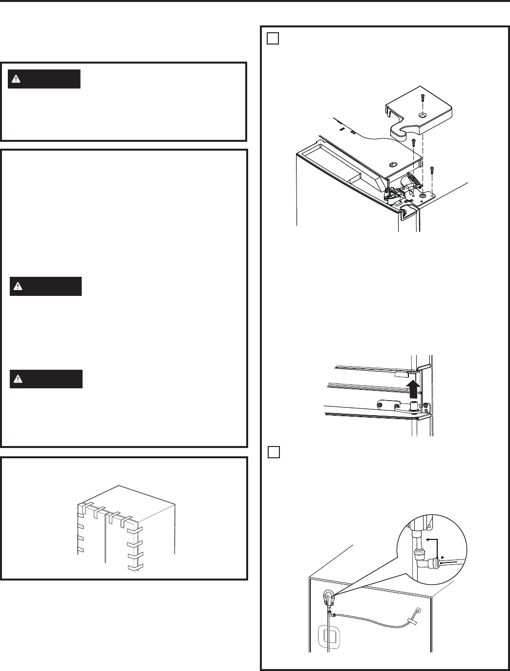
REMOVING RIGHT DOOR
A. Remove the hinge cover on top of the right
fresh food door by removing the screw using
a Phillips screwdriver.
B 8VLQJD´VRFNHWUDWFKHWGULYHUUHPRYHWKH
bolts securing the top hinge to the cabinet. Lift
the hinge support straight up to free the hinge
pin from the socket in the top of the door.
C. Remove the tape from the right door and tilt
the door away from the cabinet. Lift the door
off the center hinge pin.
D. Set the door on a non-scratching surface with
the inside up.
2
REMOVING LEFT DOOR
A. For Ice and Water Models Only: Unplug the
water line from the back of the refrigerator
and remove all tape that fixes the water line
to the refrigerator.
WARNING
)ROORZDOOVWHSVZKHQUHYHUVLQJ
WKHGRRUVZLQJ)DLOXUHWRIROORZWKHVHLQVWUXFWLRQV
leaving off parts, or overtightening screws, can lead
to the door falling off and result in injury and property
damage.
INSTALLATION INSTRUCTIONS

49-60805-1 Rev. 3 23
INSTALLATION INSTRUCTIONS
Installation Instructions
3
REMOVING CENTER HINGES AND
BRACKETS
A. 8VLQJD´$OOHQZUHQFKUHPRYHWKHKLQJH
pins from the hinge brackets.
B.8VLQJD´VRFNHWUDWFKHWGULYHUUHPRYHWKH
bolts securing the center hinge brackets to the
cabinet.
2
REMOVING LEFT DOOR (cont.)
B. Remove the hinge cover on top of the left
fresh food door by removing the screw using
a Phillips screwdriver.
C. Unplug the 3 wire connectors and move the
wires until you can see the screws holding
the hinge.
For Ice and Water Models Only: Pull the
water line very carefully.
D. 8VLQJD´VRFNHWUDWFKHWGULYHUUHPRYH
the bolts securing the top hinge to the
cabinet.
Wire
Connectors
Water Line
,FHDQG:DWHU
Models Only)
Wire Connectors
Bolts
Water Line
,FHDQG
Water
Models
Only)
For NON Ice and Water Models Only: Lift the
hinge straight up to free the hinge pin from the
socket in the top of the door and pass the wire
through the slot in the hinge. For Ice and Water
Models Only: Do not remove hinge from the
door.
E. Remove the tape from the door, open the
door 90 degrees and tilt the door away from
the cabinet. Lift the door off the center hinge
pin.
F. Set the door on a non-scratching surface with
the inside up.
INSTALLING THE REFRIGERATOR (Cont.)

24 49-60805 Rev. 3
REINSTALLING FRENCH DOORS
(on some models)
Installation Instructions
IMPORTANT NOTES
When replacing the french doors:
• Read the instructions all the way through before
starting.
CAUTION
Lifting Hazard.
Single person lift can cause injury. Use assistance
when handling, moving or lifting the refrigerator
doors.
NOTE: When moving door, to prevent damage to
door and electronics carefully place the door in a
proper location.
WARNING
To eliminate the risk of electric shock or injury
during installation, you must first unplug the
UHIULJHUDWRUEHIRUHSURFHHGLQJ)DLOXUHWRIROORZ
these instructions can result in electrical shock.
1
REINSTALLING CENTER HINGE
BRACKETS AND HINGES
A.8VLQJD´VRFNHWUDWFKHWGULYHUUHLQVWDOO
the bolts and center hinge brackets to the
cabinet.
B. 8VLQJD´$OOHQZUHQFKUHLQVWDOOWKH
hinge pins into the hinge brackets.
2
REHANGING THE RIGHT DOOR
A. Lower the refrigerator door onto the right
hinge pin.
B. Make sure the door is aligned with the
cabinet. Attach the hinge to the top of the
cabinet loosely with bolts removed earlier.
C. Make sure the gasket on the door is flush
against the cabinet and is not folded. Tighten
the bolts to 60 lb/in.(6.78 Nm).
D. Replace the right hinge cover on top of the
refrigerator using a Phillips screwdriver.
3
REHANGING THE LEFT DOOR
A. For NON Ice and Water Models Only: Pass
the wire through the slot in the hinge. Place
the hinge pin into the top of the door.
B. Lower the refrigerator door onto the left
hinge pin.
INSTALLING THE REFRIGERATOR (Cont.)
INSTALLATION INSTRUCTIONS

49-60805-1 Rev. 3 25
INSTALLATION INSTRUCTIONS
Installation Instructions
REINSTALLING FRENCH DOORS (Cont.) (on some models)
3
REHANGING THE LEFT DOOR (Cont.)
C. Make sure the door is aligned with the
cabinet. Attach the hinge to the top of the
cabinet loosely with bolts removed earlier.
D. Make sure the gasket on the door is flush
against the cabinet and is not folded. Tighten
the bolts to 60 lb/in. (6.78 Nm).
E. Plug the wire connectors together and rout the
wire inside the plastic port.
F. For Ice and Water Models Only: Put the
water line into the hole and pass through the
plastic port to the back of the refrigerator.
Plug the water line back into the fixture on
back of the refrigerator. Tape water line to
the refrigerator.
G. Replace the left hinge cover on top of the
refrigerator using a Phillips screwdriver.
Wire
Connectors
Water Line
,FHDQG:DWHU
Models Only)
Wire Connectors
Bolts
Water Line
,FHDQG
Water
Models
Only)
INSTALLING THE REFRIGERATOR (Cont.)

26 49-60805 Rev. 3
REMOVING FREEZER DRAWER
(on some models)
Installation Instructions
IMPORTANT NOTES
:KHQUHPRYLQJIUHH]HUGUDZHU
• Read the instructions all the way through before
starting.
• Provide a non-scratching work surface for the
doors.
1
REMOVE THE BASKETS
A. 2SHQWKHIUHH]HUGUDZHUXQWLOLWVWRSV
B. Pull the top basket out until it stops. Lift the
basket up on the front and out to remove.
C. The lower basket rests on a frame inside the
IUHH]HUGUDZHU/LIWWKHIURQWRIWKHEDVNHW
and pull it forward. Release the pins from the
slots on the frame to remove the basket.
2
REMOVE THE DRAWER FRONT
A. Remove the screw on each side of the
railing.
B./LIWXSRQERWKVLGHVRIWKHIUHH]HUGUDZHU
handle to separate the drawer railings from
the rail assemblies.
C. Set the drawer front on a non-scratching
surface.
D. Push the rail assemblies back into locking
position.
Screw
'UDZHU
Assembly
Rail
Assembly
INSTALLING THE REFRIGERATOR (Cont.)
INSTALLATION INSTRUCTIONS
49-60805-1 Rev. 3 27
INSTALLATION INSTRUCTIONS
Installation Instructions
REMOVING FREEZER DRAWER (on some models) (Cont.)
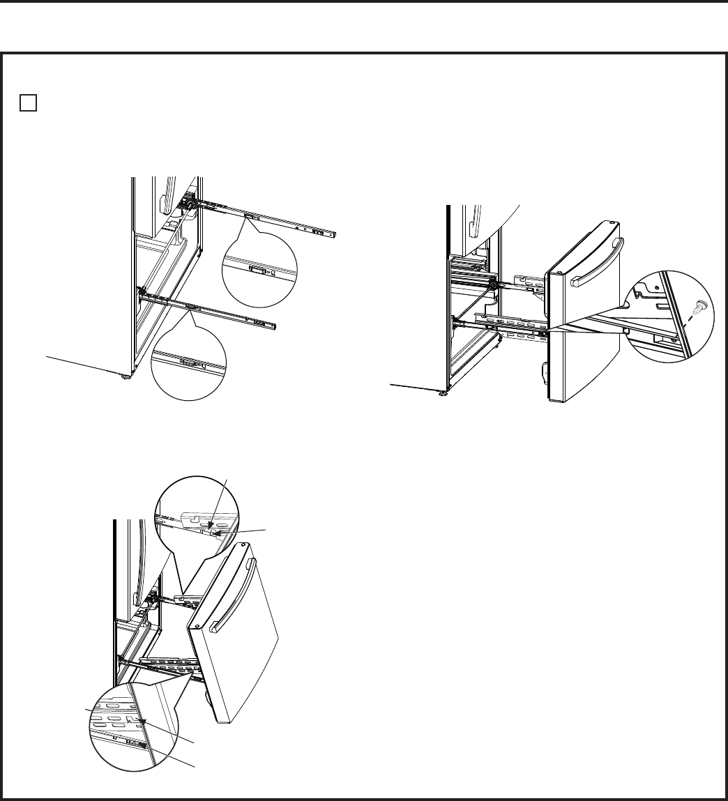
3
REINSTALL FREEZER DRAWER FRONT
A. Pull the rail assemblies to the maximum
extension.
B. Locate the slots on the inside of each slide.
C. ,QVHUWWKHKRRNVRQWKHHQGVRIWKHGUDZHU
assembly extensions into the slots near the
back of the slides.
D. /RZHUWKHIURQWHQGRIWKHIUHH]HUGUDZHU
assembly so the side tabs fit into the front slots
on the rail assemblies.
E. Replace the safety screws in both sides of the
slide assemblies.
F. Replace lower and upper baskets (see About
IUHH]HUGUDZHUSDJH
Hook
Slot
Side Tab
)URQW6ORW
INSTALLING THE REFRIGERATOR (Cont.)

28 49-60805 Rev. 3
REVERSING THE DOOR
(on some models)
Installation Instructions
WARNING
)ROORZDOOVWHSVZKHQUHYHUVLQJ
WKHGRRUVZLQJ)DLOXUHWRIROORZWKHVHLQVWUXFWLRQV
leaving off parts, or overtightening screws, can lead
to the door falling off and result in injury and property
damage.
IMPORTANT NOTES
When reversing doors:
• Read the instructions all the way through before
starting.
• Logo badge, handles, plugs and right hinge
cover are included inside the refrigerator (some
models).
• Place the screws by their related parts to avoid
using them in the wrong places.
• Provide a non-scratching work surface for the
doors.
CAUTION
Lifting Hazard.
Single person lift can cause injury. Use assistance
when handling, moving or lifting the refrigerator
doors.
NOTE: When removing door, to prevent damage to
door and electronics carefully place the door in a
proper location.
NOTE: The lower door hinge pin and hinge are
keyed and must be matched correctly for the door
to self close properly. Please follow directions
carefully.
)UHH]HUGRRULVKHDY\8VHERWKKDQGVWRVHFXUH
the door before lifting.
WARNING
To eliminate the risk of electric shock or injury
during installation, you must first unplug the
UHIULJHUDWRUEHIRUHSURFHHGLQJ)DLOXUHWRIROORZ
these instructions can result in electrical shock.
1
REMOVE THE REFRIGERATOR
DOORS
A. Tape the door shut with masking tape.
1
REMOVE THE REFRIGERATOR
DOORS (Cont.)
B. Remove right and left hinge covers on top of
the refrigerator using a Phillips screwdriver.
C. 8VLQJD´VRFNHW
ratchet driver, remove
the bolts securing
the top hinge to the
cabinet. Lift the hinge
straight up to remove.
D. Remove the tape and
tilt the fresh food door
away from the cabinet.
Lift the door off of the center hinge pin.
E. Set the fresh food door on a non-scratching
surface with the inside up.
For Models With a Freezer DRAWER:
F.8VLQJD´$OOHQZUHQFK
remove the hinge pin from
the hinge bracket. The hinge
pin will be used again on the
opposite side.
G.8VLQJD´VRFNHWUDWFKHW
driver, remove the bolts
securing the center hinge to the cabinet.
INSTALLING THE REFRIGERATOR (Cont.)
INSTALLATION INSTRUCTIONS
49-60805-1 Rev. 3 29
INSTALLATION INSTRUCTIONS
Installation Instructions
1
REMOVE THE REFRIGERATOR DOORS (Cont.)
H. Remove the button plugs on the left side of the
cabinet across from where the hinge bracket
was located and install in the holes where the
bracket was removed.
I.)OLSWKHFHQWHUKLQJH
bracket and install
on the left side of the
cabinet where the
button plugs were
removed.
J.8VLQJD´$OOHQ
wrench, install the hinge pin into the center
hinge bracket.
For Models With a Freezer DOOR:
F.7DSHWKHIUHH]HUGRRUVKXWZLWKDGKHVLYHWDSH
G.8VLQJD´$OOHQZUHQFK
remove the hinge pin from
the hinge bracket. The
hinge pin will be used
again on the opposite
side.
H. Remove the tape and tilt the door away from
the cabinet. Lift the door off of the bottom hinge
pin.
I. Using a thing-blade screwdriver remove the
button plug from the top left side of the door
and install it on the opposite side.
J. Set the door on a non-scratching surface with
the inside up.
K.8VLQJD´VRFNHW
ratchet driver, remove
the bolts securing the
center hinge to the
cabinet.
L. Locate the button plugs in the kit and install
them in the opposite side of center hinge.
M.)OLSWKHFHQWHUKLQJH
EUDFNHW8VLQJD´
socket/ratchet driver, install
the center hinge bolt on the
left side of the cabinet and
torque to 60 in-lb.
(6.78 Nm).
N.8VLQJD´$OOHQZUHQFKLQVWDOOWKHKLQJHSLQ
LQWRWKHFHQWHUKLQJHEUDFNHW'RQRWOHWWKHSLQ
go past the bottom of the bracket.
O.8VLQJD´VRFNHW
ratchet driver, remove
the screws from
the bottom hinge
bracket. These will
be reinstalled on the
other side. Pull up
on the hinge pin to
remove.
P. Using a Torx T-20
screwdriver, remove the
screw from the cabinet and
install it on the other side.
Q.8VLQJ´VRFNHW
ratchet driver, install
the bottom hinge
bracket and torque
the screws to 60
in-lb. (6.78 Nm).
Remount the hinge
and pin in the opposite hole on the cabinet.
INSTALLING THE REFRIGERATOR (Cont.)

30 49-60805 Rev. 3
Installation Instructions
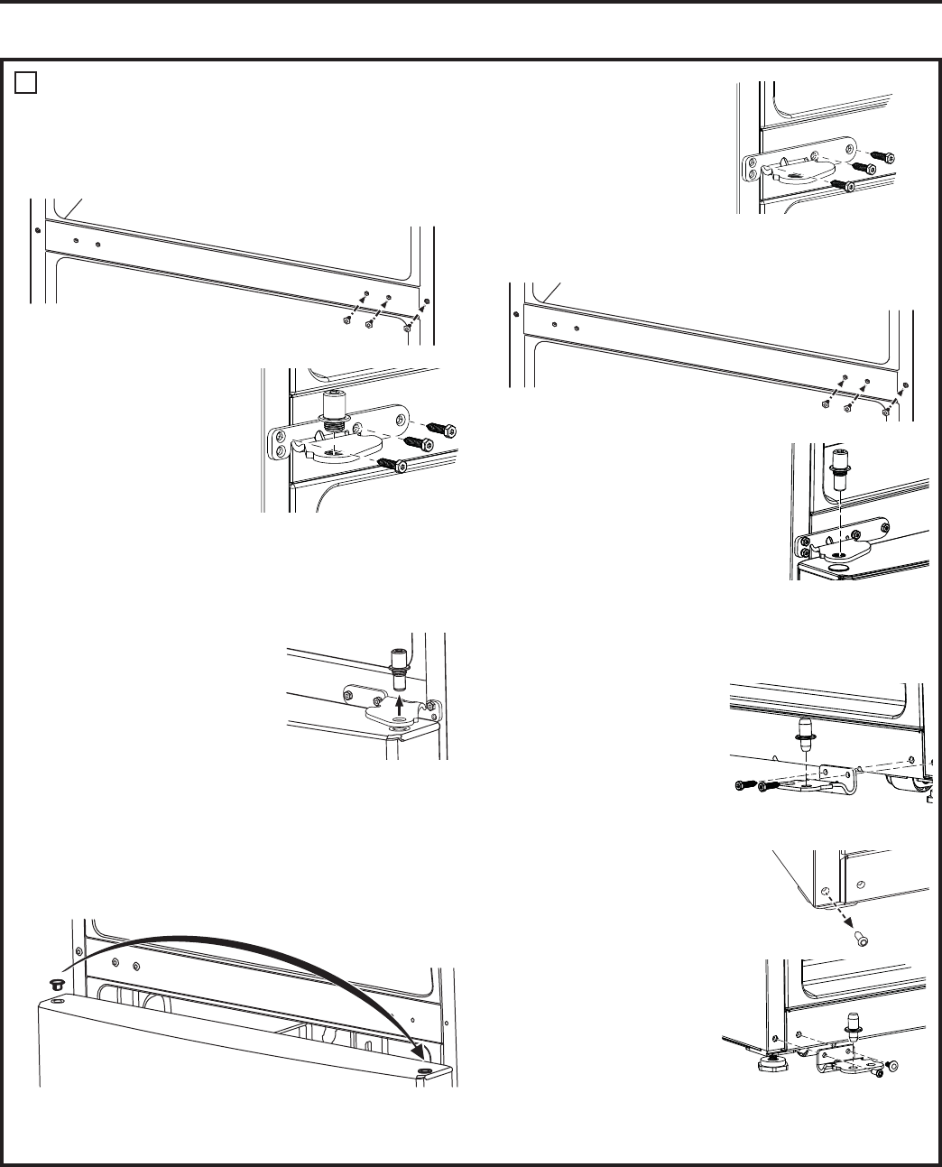
2
REINSTALL FREEZER DOOR
A. Using a Torx T-20 screwdriver, remove the
bolts securing the door stop on the bottom
right of the door.
B. Using a Trox T-20 screwdriver, remove the
plastic force closure on the bottom right of the
door.
C.)OLSWKHSODVWLFIRUFHFORVXUHDQGPRXQWLWWR
the bottom left of the door.
D.,QVWDOOWKHGRRUVWRSWRWKHERWWRPOHIWRIWKH
door.
E. /RZHUWKHIUHH]HUGRRUDQGPDNHVXUHWRLQVHUW
the hinge pin in the bottom hole of the door.
F. Straighten the door and line it up with the
FHQWHUKLQJHEUDFNHW8VLQJD´$OOHQ
wrench, turn the hinge pin until it extends
through the hinge bracket and into the door.
3
REINSTALL FRESH FOOD DOOR
A. Using a Torx T-20 screwdriver, remove the
bolts securing the door stop on the bottom
right of the door.
B. Transfer the plastic thimble to the opposite
KROH,QVWDOOWKHGRRUVWRSZLWKWKHSODVWLF
thimble on the opposite side.
C. Using a Trox T-20 screwdriver, remove the
plastic force closure on the bottom right of the
door.
D.)OLSWKHSODVWLFIRUFHFORVXUHDQGPRXQWLWWR
the bottom left of the door.
E.,QVWDOOWKHGRRUVWRSWRWKHERWWRPOHIWRIWKH
door.
F. Lower the fresh food door and make sure to
insert the hinge pin in the bottom hole of the
door.
G.5HPRYHWKHKLQJHEDVHIURPWKHKLQJH)OLS
the hinge over and remount to hinge base.
)RUFHFORVXUH
'RRUVWRS
)RUFHFORVXUH
Plastic Thimble
'RRUVWRS
Hinge base
Hinge
WARNING
)ROORZDOOVWHSVZKHQUHYHUVLQJ
WKHGRRUVZLQJ)DLOXUHWRIROORZWKHVHLQVWUXFWLRQV
leaving off parts, or overtightening screws, can lead
to the door falling off and result in injury and property
damage.
INSTALLING THE REFRIGERATOR (Cont.)
INSTALLATION INSTRUCTIONS

49-60805-1 Rev. 3 31
INSTALLATION INSTRUCTIONS
Installation Instructions
INSTALLING THE REFRIGERATOR (cont.)
3
REINSTALL FRESH FOOD DOOR
(Cont.)
H.,QVHUWWKHWRSKLQJHSLQLQVLGHWKHKROHLQWKH
top left of the fresh food door. Make sure the
door is aligned with the cabinet. Attach the
hinge to the top of the cabinet loosely with
the bolts that were removed previously.
Make sure the gasket
on the door is flush
against the cabinet
and not folded.
Support the door on
the handle side and
make sure the door is
straight and the gap
between the doors is
even across the front.
While holding the
door in place, tighten
the screws to 60 in-lb.
(6.78 Nm).
For Models with a Freezer DRAWER:
I. Remove the front insert from the left hinge
FRYHU,QVWDOOWKHOHIWKLQJHFRYHUXVLQJD
Phillips screwdriver and the screw removed
earlier.
J. ,QVWDOOWKHIURQWLQVHUWLQWRWKHULJKWKLQJH
FRYHU,QVWDOOWKHULJKWKLQJHFRYHUXVLQJD
Phillips screwdriver and the screws removed
earlier.
For Models with a Freezer DOOR:
I. Locate the left hinge
cover that comes
with the kit. Using a
Phillips screwdriver,
install the cover with
the screws provided.
)URQWLQVHUW
)URQW
insert
3
REINSTALL FRESH FOOD DOOR
(Cont.)
J. Locate the insert for the right hinge cover that
comes with the kit and install.
K. Using a Phillips screwdriver, install the right
hinge cover with screws provided.
4
TRANSFER HANDLE
MOUNTING FASTENERS
A. Remove the plug from the lower right whole.
B. Using a Phillips screwdriver remove the
screws holding the mounting brackets from
the left side and install them on the right side.
5
INSTALLING LOGO BADGE
A. Locate the new logo
badge from the kit.
Remove the adhesive
backing paper and align
the pins on the back
of the badge with the
holes in the door. Apply
pressure to the badge to
ensure it sticks to the door.
B. Locate the button plug from
the kit and install it in the
opposite side of handle.
)URQWLQVHUW
Remove plug

32 49-60805 Rev. 3
Installation Instructions
INSTALLING THE REFRIGERATOR (cont.)
CONNECTING TO THE HOUSE WATER LINE
(Icemaker models only)
A cold water supply is required for automatic icemaker
RSHUDWLRQ,IWKHUHLVQRWDFROGZDWHUVXSSO\\RXZLOO
QHHGWRSURYLGHRQH6HH,QVWDOOLQJWKH:DWHU/LQH
section.
NOTES:
• Before making the connection to the refrigerator, be
sure the refrigerator power cord is not plugged into
the wall outlet.
,I\RXUUHIULJHUDWRUGRHVQRWKDYHDZDWHUILOWHU
we recommend installing one if your water supply
has sand or particles that could clog the screen of
WKHUHIULJHUDWRU¶VZDWHUYDOYH,QVWDOOLWLQWKHZDWHU
OLQHQHDUWKHUHIULJHUDWRU,IXVLQJ6PDUW&RQQHFW
5HIULJHUDWRU7XELQJ.LW\RXZLOOQHHGDQDGGLWLRQDO
WXEH:;;WRFRQQHFWWKHILOWHU'RQRWFXW
plastic tube to install filter.
• Before connecting the water line to the house, purge
the house line for at least 2 minutes.
A. If you are using copper tubing, place a
compression nut and ferrule (sleeve) onto the end
of the tubing coming from the house cold water
supply.
If you are using the SmartConnect™ tubing,
the nuts are already assembled to the tubing.
B. If you are using copper tubing, insert the end of
the tubing into the refrigerator connection, at the
back of the refrigerator, as far as possible. While
holding the tubing, tighten the fitting.
,I\RXDUHXVLQJ6PDUW&RQQHFWWXELQJLQVHUW
the molded end of the tubing into the refrigerator
connection, at the back of the refrigerator, and
tighten the compression nut until it is hand tight.
Then tighten one additional turn with a wrench.
Over tightening may cause leaks.
C. )DVWHQWKHWXELQJLQWRWKHFODPSSURYLGHGWRKROGLW
in position. You may need to pry open the clamp.
One of the illustrations below will look like the
connection on your refrigerator.
WARNING
Connect to potable water supply only.
A cold water supply is required for automatic icemaker
operation. The water pressure must be between 40
and 120 psi (275-827 kilopascals).
WARNING
ELECTRIC SHOCK HAZARD
$WWDFKWXELQJFODPSXVLQJH[LVWLQJKROHRQO\'2127
drill into the refrigerator.
Refrigerator
connection
SmartConnect™
tubing
,FHPDNHUILOO
tubing
Tubing
clamp
´&RSSHU
tubing
Icemaker-Ready Models
Icemaker-Installed Models
TURN ON THE WATER SUPPLY
(Icemaker models only)
Turn the water on at the
shutoff valve (house water
supply) and check for any
leaks.
PLUG IN THE REFRIGERATOR
On models with an icemaker,
before plugging in the
refrigerator, make sure the
icemaker power switch is set to
the 0 (off) position.
See the grounding information
attached to the power cord.
INSTALLATION INSTRUCTIONS
SmartConnect™
tubing
Refrigerator
connection

49-60805-1 Rev. 3 33
INSTALLATION INSTRUCTIONS
Installation Instructions
INSTALLING THE REFRIGERATOR (cont.)
PUT THE REFRIGERATOR IN
PLACE
Move the refrigerator to its final location.
LEVEL THE REFRIGERATOR
Adjustable legs at the front corners of the
refrigerator should be set so the refrigerator is firmly
positioned on the floor, and the front is raised just
enough that the door closes easily when opened
about halfway.
To adjust the leveling legs, turn the
legs clockwise to raise the refrigerator,
counterclockwise to lower it.
LEVEL THE REFRIGERATOR
DOORS
(on some models)
Remember a level refrigerator is necessary for
JHWWLQJWKHGRRUVSHUIHFWO\HYHQ,I\RXQHHG
help, review the previous section on leveling the
refrigerator.
,IWKHGRRUVUHPDLQXQHYHQWXUQWKHDGMXVWDEOHSLQ
WRUDLVHWKHORZHVWGRRUXVLQJD´DOOHQZUHQFKWR
turn the pin.
When
the left
door is
lower than
the right
door.
When
the left
door is
higher
than
the right
door.
Adjustment point
Refrigerator suggested assembly
Shelves shown in the location for best energy efficiency.
GWE19J
19 cuft. Models
French Door with
Freezer Drawer
GYE18J, PYE18H
18 cuft. Models
French Door with Freezer Drawer

34 49-60805 Rev. 3
Installation Instructions
Refrigerator suggested assembly (cont.)
Shelves shown in the location for best energy efficiency.
,FHPDNHULQWKH
door is available
for all 24 and
26 french door
models.
GBE21D, GBE21A
21 cuft. Models
Single Door with Freezer Door
GDE21D, GDE21E,
PDE21K, GDE25E
21, 25 cuft. Models
Single Door with Freezer Drawer
GNE21D, GNE21F,
PNE21K, PNE21N
21 cuft. Models
French Door with Freezer Drawer
GNE25D, GNE25J, PNE25J,
CNE25S, PNE25N, GNE27J
25, 27 cuft. Models
French Door with Freezer Drawer
GFE24J, PFE24J, CFE24S,
PFE24H 24 cuft. Models
French Door with Freezer Drawer
GFE26J
26 cuft. Models
French Door with Freezer Drawer
GNE27E
27 cuft. Models
French Door with Freezer Drawer
INSTALLATION INSTRUCTIONS

49-60805-1 Rev. 3 35
INSTALLATION INSTRUCTIONS
Installation Instructions
INSTALLING THE WATER LINE
BEFORE YOU BEGIN
5HFRPPHQGHGFRSSHUZDWHUVXSSO\NLWVDUH:;;
:;;RU:;;GHSHQGLQJRQWKHDPRXQWRI
tubing you need. Approved plastic water supply
lines are SmartConnect
™
Refrigerator Tubing
:;;:;;DQG:;;
When connecting your refrigerator to a GE
Appliances Reverse Osmosis Water System, the only
DSSURYHGLQVWDOODWLRQLVZLWKD*($SSOLDQFHV59.LW
)RURWKHUUHYHUVHRVPRVLVZDWHUV\VWHPVIROORZWKH
manufacturer’s recommendations.
,IWKHZDWHUVXSSO\WRWKHUHIULJHUDWRULVIURPD5HYHUVH
2VPRVLV:DWHU)LOWUDWLRQ6\VWHP52$1'WKH
refrigerator also has a water filter, use the refrigerator’s
filter bypass plug. Using the refrigerator’s water
filtration cartridge in conjunction with an RO water filter
can result in hollow ice cubes. Some models do not
come equipped with the filter bypass plug. To obtain a
IUHHE\SDVVSOXJFDOO*(&$5(6,Q&DQDGDFDOO
800.561.3344.
This water line installation is not warranted by the
UHIULJHUDWRURULFHPDNHUPDQXIDFWXUHU)ROORZWKHVH
LQVWUXFWLRQVFDUHIXOO\WRPLQLPL]HWKHULVNRIH[SHQVLYH
water damage.
Water hammer (water banging in the pipes) in house
plumbing can cause damage to refrigerator parts and
lead to water leakage or flooding. Call a qualified
plumber to correct water hammer before installing the
water supply line to the refrigerator.
To prevent burns and product damage, do not hook
up the water line to the hot water line.
'RQRWLQVWDOOWKHLFHPDNHUWXELQJLQDUHDVZKHUH
WHPSHUDWXUHVIDOOEHORZIUHH]LQJ
When using any electrical device (such as a power
drill) during installation, be sure the device is double
insulated or grounded in a manner to prevent the
KD]DUGRIHOHFWULFVKRFNRULVEDWWHU\SRZHUHG
All installations must be in accordance with local
plumbing code requirements.
WHAT YOU WILL NEED
• Copper or SmartConnect™ Refrigerator Tubing kit,
´RXWHUGLDPHWHUWRFRQQHFWWKHUHIULJHUDWRUWRWKH
ZDWHUVXSSO\,IXVLQJFRSSHUEHVXUHERWKHQGVRI
the tubing are cut square.
To determine how much tubing you need: measure
the distance from the water valve on the back of the
refrigerator to the water supply pipe. Be sure there is
sufficient extra tubing to allow the refrigerator to move
out from the wall after installation.
6PDUW&RQQHFW5HIULJHUDWRU7XELQJ.LWVDUH
available in the following lengths:
¶P ±:;;
¶P ±:;;
¶P ±:;;
WARNING
Connect to potable water supply only.
A cold water supply is required for automatic
icemaker operation. The water pressure must be
between 40 and 120 psi (275-827 kilopascals)

36 49-60805 Rev. 3
INSTALLING THE WATER LINE (cont.)
WHAT YOU WILL NEED (cont.)
NOTE: The only GE Appliances approved
plastic tubing is that supplied in SmartConnect™
5HIULJHUDWRU7XELQJNLWV'RQRWXVHDQ\RWKHUSODVWLF
water supply line because the line is under pressure
at all times. Certain types of plastic will crack or
rupture with age and cause water damage to your
home.
• A GE Appliances water supply kit (containing
tubing, shutoff valve and fittings listed below) is
available at extra cost from your dealer or from
Parts and Accessories, 877.959.8688 (in Canada
1.800.661.1616).
• A cold water supply. The water pressure must be
between 20 and 120 p.s.i. (138-827 kPa).
• Power drill.
´RUDGMXVWDEOHZUHQFK
• Straight and Phillips blade screwdriver.
7ZR´RXWHUGLDPHWHUFRPSUHVVLRQQXWVDQG
ferrules (sleeves)—to connect the copper tubing to
the shutoff valve and the refrigerator water valve.
OR
,I\RXDUHXVLQJD6PDUW&RQQHFW5HIULJHUDWRU
Tubing kit, the necessary fittings are preassembled
to the tubing.
,I\RXUH[LVWLQJFRSSHUZDWHUOLQHKDVDIODUHGILWWLQJ
at the end, you will need an adapter (available at
plumbing supply stores) to connect the water line to
the refrigerator OR you can cut off the flared fitting
with a tube cutter and then use a compression
ILWWLQJ'RQRWFXWIRUPHGHQGIURP6PDUW&RQQHFW
Refrigerator tubing.
• Shutoff valve to connect to the cold water line.
The shutoff valve should have a water inlet with a
PLQLPXPLQVLGHGLDPHWHURI´DWWKHSRLQWRI
FRQQHFWLRQWRWKH&2/':$7(5/,1(6DGGOHW\SH
shutoff valves are included in many water supply
kits. Before purchasing, make sure a saddle-type
valve complies with your local plumbing codes.
Installation Instructions
,QVWDOOWKHVKXWRIIYDOYHRQWKHQHDUHVWIUHTXHQWO\XVHG
drinking water line.
2
CHOOSE THE VALVE LOCATION
Choose a location for the valve that is easily
DFFHVVLEOH,WLVEHVWWRFRQQHFWLQWRWKHVLGHRI
a vertical water pipe. When it is necessary to
FRQQHFWLQWRDKRUL]RQWDOZDWHUSLSHPDNHWKH
connection to the top or side, rather than at the
bottom, to avoid drawing off any sediment from
the water pipe.
1
SHUT OFF THE MAIN WATER
SUPPLY
Turn on the nearest faucet long enough to clear
the line of water.
3
DRILL THE HOLE FOR THE
VALVE
'ULOOD´KROHLQWKHZDWHUSLSHHYHQLIXVLQJ
a self-piercing valve), using a sharp bit. Remove
any burrs resulting from drilling the hole in the
pipe.
Take care not to allow water to drain into
the drill.
)DLOXUHWRGULOOD´KROHPD\UHVXOWLQUHGXFHG
ice production or smaller cubes.
INSTALLATION INSTRUCTIONS

49-60805-1 Rev. 3 37
INSTALLATION INSTRUCTIONS
Installation Instructions
INSTALLING THE WATER LINE (cont.)
4
FASTEN THE SHUTOFF VALVE
)DVWHQWKHVKXWRIIYDOYHWRWKHFROGZDWHUSLSH
with the pipe clamp.
NOTE: Commonwealth of Massachusetts
Plumbing Codes 248CMR shall be adhered
to. Saddle valves are illegal and use is not
permitted in Massachusetts. Consult with your
licensed plumber.
7
FASTEN THE SHUTOFF VALVE
Place the compression nut and ferrule (sleeve)
for copper tubing onto the end of the tubing
and connect it to the shutoff valve.
Make sure the tubing is fully inserted into
the valve. Tighten the compression nut securely.
)RUSODVWLFWXELQJIURPD6PDUW&RQQHFW
Refrigerator Tubing kit, insert the molded end
of the tubing into the shutoff valve and tighten
compression nut until it is hand tight, then
tighten one additional turn with a wrench. Over
tightening may cause leaks.
NOTE: Commonwealth of Massachusetts
Plumbing Codes 248CMR shall be adhered
to. Saddle valves are illegal and use is not
permitted in Massachusetts. Consult with your
licensed plumber.
5
TIGHTEN THE PIPE CLAMP
Tighten the clamp screws until the sealing
washer begins to swell.
NOTE: 'RQRWRYHUWLJKWHQRU\RXPD\FUXVK
the tubing.
8
FLUSH OUT THE TUBING
Turn the main water supply on and flush out
the tubing until the water is clear.
Shut the water off at the water valve after about
one quart (1 liter), or 2 minutes, of water has
been flushed through the tubing.
6
ROUTE THE TUBING
Route the tubing between the cold water line
and the refrigerator.
Route the tubing through a hole drilled in the
wall or floor (behind the refrigerator or adjacent
base cabinet) as close to the wall as possible.
Pipe Clamp
Vertical Cold
Water Pipe
Saddle-Type
Shutoff Valve
Washer
,QOHW(QG
Pipe Clamp
Clamp
Screw
Saddle-Type
Shutoff Valve
Compression Nut
Packing Nut
Outlet Valve
)HUUXOHVOHHYH
SmartConnect
™
Tubing
To complete the installation of the refrigerator, go
EDFNWR6WHSLQ,QVWDOOLQJWKH5HIULJHUDWRU
