
AIR CONDITIONER
Duct type
DESIGN & TECHNICAL MANUAL
INDOOR
ADUH09LUAS1
ADUH12LUAS1
ADUH18LUAS1
OUTDOOR
AOUH09LUAS1 AOUH12LUAS1
AOUH18LUAS1
DR_AR055EF_02
2021.06.30

Notices:
• Product specifications and design are subject to change without notice for future improvement.
• For further details, please check with our authorized dealer.
Trademarks
FGLair
™
is trademark of Fujitsu General Limited in the United States, other countries or both.
Google Play
™
is trademark of Google Inc.
App Store
®
is a service mark of Apple Inc., registered in the U.S. and other countries.
Copyright © 2021 Fujitsu General Limited. All rights reserved.

CONTENTS
Part 1. INDOOR UNIT...........................................................................1
1. Specifications................................................................................................2
2. Dimensions....................................................................................................4
2-1. Models: ADUH09LUAS1 and ADUH12LUAS1 ................................................................4
2-2. Model: ADUH18LUAS1....................................................................................................5
2-3. Installation space requirement .........................................................................................6
2-4. Maintenance space requirement......................................................................................7
3. Wiring diagrams ............................................................................................8
3-1. Models: ADUH09LUAS1, ADUH12LUAS1, and ADUH18LUAS1 ....................................8
4. Capacity table................................................................................................9
4-1. Cooling capacity...............................................................................................................9
4-2. Heating capacity ............................................................................................................11
5. Fan performance .........................................................................................13
5-1. Air velocity and temperature distributions ......................................................................13
5-2. Fan performance curve..................................................................................................19
5-3. Airflow ............................................................................................................................25
6. Operation noise (sound pressure).............................................................28
6-1. Noise level curve............................................................................................................28
6-2. Sound level check point .................................................................................................30
7. Safety devices .............................................................................................31
8. External input and output...........................................................................32
8-1. External input.................................................................................................................32
8-2. External output...............................................................................................................34
8-3. Combination of external input and output.......................................................................36
8-4. Details of function ..........................................................................................................39
9. Function settings .......................................................................................64
9-1. Function settings on indoor unit .....................................................................................64
9-2. Function settings by using remote controller..................................................................66
10. Accessories.................................................................................................74
10-1.Models: ADUH09LUAS1, ADUH12LUAS1, and ADUH18LUAS1 .................................74
11. Optional parts .............................................................................................75
11-1.Controllers ....................................................................................................................75
11-2.Others...........................................................................................................................76

Part 2. OUTDOOR UNIT.....................................................................79
1. Specifications..............................................................................................80
2. Dimensions..................................................................................................81
2-1. Models: AOUH09LUAS1................................................................................................81
2-2. Models: AOUH12LUAS1 and AOUH18LUAS1 ..............................................................82
3. Installation space ........................................................................................83
3-1. Models: AOUH09LUAS1, AOUH12LUAS1, and AOUH18LUAS1 .................................83
4. Refrigerant circuit .......................................................................................86
4-1. Models: AOUH09LUAS1................................................................................................86
4-2. Models: AOUH12LUAS1 and AOUH18LUAS1 ..............................................................87
5. Wiring diagrams ..........................................................................................88
5-1. Model: AOUH09LUAS1 .................................................................................................88
5-2. Models: AOUH12LUAS1 and AOUH18LUAS1 ..............................................................89
6. Capacity compensation rate for pipe length and height difference........90
6-1. Model: AOUH09LUAS1 .................................................................................................90
6-2. Model: AOUH12LUAS1 .................................................................................................91
6-3. Model: AOUH18LUAS1 .................................................................................................92
7. Additional charge calculation ....................................................................93
7-1. Model: AOUH09LUAS1 .................................................................................................93
7-2. Model: AOUH12LUAS1 .................................................................................................93
7-3. Model: AOUH18LUAS1 .................................................................................................93
8. Airflow..........................................................................................................94
8-1. Model: AOUH09LUAS1 .................................................................................................94
8-2. Model: AOUH12LUAS1 .................................................................................................94
8-3. Model: AOUH18LUAS1 .................................................................................................95
9. Operation noise (sound pressure).............................................................96
9-1. Noise level curve............................................................................................................96
9-2. Sound level check point .................................................................................................97
10. Electrical characteristics............................................................................98
11. Safety devices .............................................................................................99
12. Accessories...............................................................................................100
12-1.Models: AOUH09LUAS1, AOUH12LUAS1, and AOUH18LUAS1 ..............................100
CONTENTS (continued)

Part 1. INDOOR UNIT
DUCT TYPE:
ADUH09LUAS1
ADUH12LUAS1
ADUH18LUAS1
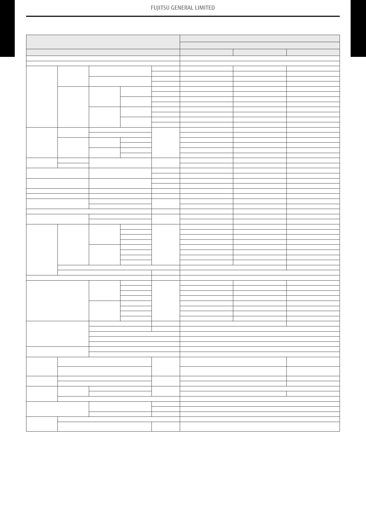
1. Specifications
Type
Duct
Inverter heat pump
Model name ADUH09LUAS1 ADUH12LUAS1 ADUH18LUAS1
Power supply 208/230 V ~ 60 Hz
Available voltage range 187—253 V
Capacity
Cooling
Rated
kW 2.64 3.52 5.02
Btu/h 9,000 12,000 17,100
Min.—Max.
kW 0.90—3.20 0.90—4.00 0.90—5.90
Btu/h 3,100—11,000 3,100—13,600 3,100—20,100
Heating
47 °FDB
(Outdoor temp.)
Rated
kW 3.52 4.69 6.33
Btu/h 12,000 16,000 21,600
Min.—Max.
kW 0.90—4.70 0.90—5.70 0.90—7.50
Btu/h 3,100—16,000 3,100—19,400 3,100—25,600
17 °FDB
(Outdoor temp.)
Rated
kW 2.17 3.08 4.22
Btu/h 7,400 10,500 14,400
Max.
kW 3.08 4.98 5.75
Btu/h 10,500 17,000 19,600
Input power
Cooling
Rated
kW
0.66 0.94 1.37
Max. 1.05 2.06 2.05
Heating
47 °FDB
(Outdoor temp.)
Rated 0.89 1.30 1.71
Max. 1.89 1.79 2.57
17 °FDB
(Outdoor temp.)
Rated 0.78 1.07 1.49
Max. 1.42 2.01 2.56
Current
Cooling
Rated A
3.3 4.2 6.1
Heating 4.5 5.8 7.6
EER Cooling
kW/kW 4.00 3.74 3.66
Btu/hW 13.6 12.8 12.5
COP Heating
kW/kW 3.96 3.60 3.70
Btu/hW 13.5 12.3 12.6
SEER Cooling Btu/hW 20.0 20.2 20.2
HSPF Heating Btu/hW 11.7 11.5 11.4
Power factor
Cooling
%
87.0 97.3 97.6
Heating 86.0 97.5 97.8
Moisture removal pints/h (L/h) 1.5 (0.7) 2.7 (1.3) 4.2 (2.0)
Maximum operating current *1
Cooling
A
6.8 9.8 11.8
Heating 9.3 11.3 14.8
Fan
Airflow rate
Cooling
HIGH
CFM (m
3
/h)
353 (600) 383 (650) 553 (940)
MED 324 (550) 353 (600) 518 (880)
LOW 294 (500) 324 (550) 482 (820)
QUIET 265 (450) 283 (480) 441 (750)
Heating
HIGH 353 (600) 383 (650) 553 (940)
MED 324 (550) 353 (600) 518 (880)
LOW 294 (500) 324 (550) 482 (820)
QUIET 265 (450) 283 (480) 441 (750)
Type × Q'ty Sirocco × 2 Sirocco × 3
Motor output W 81
Recommended static pressure inWG (Pa) 0 to 0.36 (0 to 90)
Sound pressure level *2
Cooling
HIGH
dB (A)
28 29 32
MED 27 28 30
LOW 26 27 29
QUIET 25 26 27
Heating
HIGH 28 29 32
MED 26 28 30
LOW 25 27 29
QUIET 24 24 27
Heat exchanger type
Dimensions (H × W × D) in (mm) 294 × 500 × 39.9 294 × 700 × 39.9
Fin pitch FPI 1.3
Rows × Stages 3 × 14
Pipe type Copper tube
Fin type Aluminum
Enclosure
Material Steel sheet
Color —
Dimensions
(H × W × D)
Net
in (mm)
7-13/16 × 27-9/16 × 24-7/16
(198 × 700 × 620)
7-13/16 × 35-7/16 × 24-7/16
(198 × 900 × 620)
Gross
10-7/8 × 38-1/8 × 30-3/8
(276 × 968 × 772)
10-7/8 × 46 × 30-3/8
(276 × 1,168 × 772)
Weight
Net
lb (kg)
37 (17) 44 (20)
Gross 49 (22) 57 (26)
Connection pipe
Size
Liquid
in (mm)
Ø1/4 (Ø6.35)
Gas Ø3/8 (Ø9.52) Ø1/2 (Ø12.70)
Method Flare
Operation range
Cooling
°F (°C) 64 to 90 (18 to 32)
%RH 80 or less
Heating °F (°C) 60 to 86 (16 to 30)
Drain hose
Material HARD PVC
Size in (mm)
Ø3/4 (Ø20.7) [I.D.]
Ø1-1/16 (Ø26.6) [O.D.]
- 2 -
1. Specifications
DUCT TYPE
ADUH09-18LUAS1
DUCT TYPE
ADUH09-18LUAS1

Type
Duct
Inverter heat pump
Model name ADUH09LUAS1 ADUH12LUAS1 ADUH18LUAS1
NOTES:
• Specifications are based on the following conditions:
– Cooling: Indoor temperature of 80 °FDB/67 °FWB(26.67 °CDB/19.44 °CWB), and outdoor temperature of 95 °FDB/75 °FWB (35 °CDB/23.9 °CWB).
– Heating: Indoor temperature of 70 °FDB/59 °FWB (21.11 °CDB/15 °CWB), and outdoor temperature of 47 °FDB /43 °FWB (8.33 °CDB/6.11°CWB).
– Standard static pressure: 0.10 inWG (25 Pa)
– Pipe length: 24 ft 7 in (7.5 m), Height difference: 0 m. (Between outdoor unit and indoor unit.)
• Protective function might work when using it outside the operation range.
• *1: Maximum current:
– The maximum value when operated within the operation range.
– The total current of indoor unit and outdoor unit.
• *2: Sound pressure level:
– Measured values in manufacturer’s anechoic chamber.
– Because of the surrounding sound environment, the sound levels measured in actual installation conditions might be higher than the specified values here.
• *3: Available on Google Play
™
store or on App Store
®
. Optional WLAN adapter is also required. For details, refer to the setting manual.
- 3 -
1. Specifications
DUCT TYPE
ADUH09-18LUAS1
DUCT TYPE
ADUH09-18LUAS1

2. Dimensions
2-1. Models: ADUH09LUAS1 and ADUH12LUAS1
Unit: in (mm)
Rear view
View A
Top view
Side view
Front view
Bottom view
Drain port
2 (51)
22-5/8 (574)
6-17/8 (174)
2-13/16 (71)
6 (152)
3-15/16 (100) x 6 = 23-5/8 (600)
3-7/32 (82)
1-7/8 (48)
25-9/16 (650)
28-7/8 (734)
1-3/16 (30)
14-13/16 (377)
6-7/16
(163)
4-11/16 (119)
3-1/2 (89)
3-1/16 (78)
2-3/16 (55)
1-7/8 (47)
3/8 (10)
24-7/16 (620)
14-5/8 (371)
10-3/8 (264)
5-11/16
(144)
2-11/16
(69)
25-9/16 (650)
26-1/8 (664)
27-9/16 (700)
1-11/16 (43)
1-1/4 (31)
7-13/16 (198)
6-5/8 (168)
5-15/16
(151)
3-1/16 (78) 2-3/16 (55)
- 4 -
2-1. Models: ADUH09LUAS1 and ADUH12LUAS1 2. Dimensions
DUCT TYPE
ADUH09-18LUAS1
DUCT TYPE
ADUH09-18LUAS1

2-2. Model: ADUH18LUAS1
Unit: in (mm)
Rear view
View A
Top view
Side view
Front view
Bottom view
Drain port
2 (51)
30-1/2 (774)
6-7/8 (174)
2-13/16 (71)
6 (152)
3-7/16
(87)
2-3/16
(56)
33-7/16 (850)
36-3/4 (934)
3-15/16 (100) × 8 = 31-1/2 (800)
1-3/16 (30)
14-13/16 (377)
6-7/16
(163)
4-11/16 (119)
3-1/2 (89)
3-1/16 (78)
2-3/16 (55)
1-7/8 (47)
3/8 (10)
24-7/16 (620)
14-5/8 (371)
10-3/8 (264)
5-11/16
(144)
2-11/16
(69)
33-7/16 (850)
34 (864)
35-7/16 (900)
1-11/16 (43)
1-1/4
(31)
7-13/16
(198)
6-5/8
(168)
5-15/16
(151)
3-1/16
(78)
2-3/16 (55)
A
- 5 -
2-2. Model: ADUH18LUAS1 2. Dimensions
DUCT TYPE
ADUH09-18LUAS1
DUCT TYPE
ADUH09-18LUAS1

2-3. Installation space requirement
Provide sufficient installation space for product safety.
In ceiling-concealed installations:
Left
side
Strong and durable ceiling
Right
side
6 (150)
or more
16 (400)
or more
Service access Ceiling
99 (2,500) or more
(When no ceiling)
Floor
10 (240) or more
1 (20) or more
1 (20) or more
12 (300) or more
Unit: in (mm)
Indoor unit
In wall-concealed installations:
1 (10)
or less
1 (10)
or less
Left side
Strong and
durable floor
Right side
(PIPE side)
Grille
Inlet air
Strong and
durable floor
6
(150)
or more
4 (100)
or more
12 (300)
or more
1 (20)
or more
1 (20)
or more
6 (150)
or more
Unit: in (mm)
Left side
Strong and
durable floor
Right side
(PIPE side)
Duct
Grille
Inlet air
Strong and
durable floor
6
(150)
or more
4 (100)
or more
12 (300)
or more
1 (20)
or more
1 (20)
or more
6 (150)
or more
- 6 -
2-3. Installation space requirement 2. Dimensions
DUCT TYPE
ADUH09-18LUAS1
DUCT TYPE
ADUH09-18LUAS1

2-4. Maintenance space requirement
For future maintenance and service access, provide sufficient maintenance space.
NOTE: Do not place any wiring or illumination in the maintenance space, as they will impede ser-
vice.
Service access
Unit
Control
box
or more
Service space
12 (300)
12 (300)
or more
4 (100)
or more
Unit: in (mm)
- 7 -
2-4. Maintenance space requirement 2. Dimensions
DUCT TYPE
ADUH09-18LUAS1
DUCT TYPE
ADUH09-18LUAS1

3. Wiring diagrams
3-1. Models: ADUH09LUAS1, ADUH12LUAS1, and
ADUH18LUAS1
- 8 -
3-1. Models: ADUH09LUAS1, ADUH12LUAS1, and ADUH18LUAS1 3. Wiring diagrams
DUCT TYPE
ADUH09-18LUAS1
DUCT TYPE
ADUH09-18LUAS1

4. Capacity table
Capacity tables show each of following values calculated based on the outdoor temperature and the
indoor temperature, under given Airflow Rate (AFR):
For cooling capacity: Total Capacity (TC), Sensible Heat Capacity (SHC), and Input Power (IP)
For heating capacity: Total Capacity (TC) and Input Power (IP)
4-1. Cooling capacity
¢ Model: ADUH09LUAS1
AFR CFM 353
Indoor temperature
°FDB 64 70 75 80 85 90
°FWB 54 60 63 67 71 73
Outdoor temperature
°FDB
TC SHC IP TC SHC IP TC SHC IP TC SHC IP TC SHC IP TC SHC IP
kBtu/h kW kBtu/h kW kBtu/h kW kBtu/h kW kBtu/h kW kBtu/h kW
14 8.43 6.91 0.23 9.39 6.95 0.23 9.71 7.55 0.23 10.67 8.18 0.23 11.31 8.15 0.24 11.95 8.68 0.24
23 7.99 6.55 0.26 8.90 6.59 0.26 9.21 7.16 0.26 10.12 7.76 0.27 10.72 7.73 0.27 11.33 8.23 0.27
32 7.55 6.18 0.27 8.41 6.22 0.28 8.70 6.76 0.28 9.56 7.33 0.28 10.13 7.30 0.28 10.70 7.77 0.29
41 7.47 5.82 0.27 8.32 5.86 0.28 8.60 6.37 0.28 9.45 6.90 0.28 10.02 6.87 0.28 10.58 7.32 0.29
50 7.67 5.46 0.27 8.54 5.50 0.27 8.83 5.98 0.27 9.70 6.48 0.28 10.29 6.45 0.28 10.87 6.87 0.28
59 7.16 5.28 0.28 7.98 5.31 0.28 8.25 5.78 0.28 9.06 6.26 0.29 9.61 6.23 0.29 10.15 6.64 0.29
67 8.57 6.22 0.45 9.55 6.25 0.46 9.88 6.80 0.46 10.85 7.37 0.47 11.50 7.34 0.47 12.15 7.82 0.48
77 8.11 5.95 0.51 9.03 5.99 0.52 9.34 6.51 0.52 10.26 7.05 0.53 10.88 7.02 0.53 11.49 7.48 0.54
87 7.58 5.83 0.58 8.45 5.87 0.59 8.74 6.38 0.60 9.60 6.91 0.61 10.18 6.88 0.61 10.75 7.33 0.62
95 7.11 5.57 0.64 7.92 5.60 0.65 8.19 6.09 0.65 9.00 6.60 0.66 9.54 6.57 0.67 10.08 7.00 0.67
104 6.04 5.28 0.60 6.73 5.31 0.61 6.96 5.78 0.62 7.65 6.26 0.63 8.11 6.23 0.63 8.57 6.64 0.64
115 5.55 5.24 0.51 6.19 5.27 0.52 6.40 5.73 0.52 7.03 6.21 0.53 7.45 6.19 0.54 7.87 6.59 0.54
AFR
m
3
/h
600
Indoor temperature
°CDB 17.8 21.1 23.9 26.7 29.4 32.2
°CWB 12.2 15.6 17.2 19.4 21.7 22.8
Outdoor temperature
°CDB
TC SHC IP TC SHC IP TC SHC IP TC SHC IP TC SHC IP TC SHC IP
kW kW kW kW kW kW
-10.0 2.47 2.02 0.23 2.75 2.04 0.23 2.85 2.21 0.23 3.13 2.40 0.23 3.32 2.39 0.24 3.50 2.55 0.24
-5.0 2.34 1.92 0.26 2.61 1.93 0.26 2.70 2.10 0.26 2.97 2.27 0.27 3.14 2.27 0.27 3.32 2.41 0.27
0.0 2.21 1.81 0.27 2.47 1.82 0.28 2.55 1.98 0.28 2.80 2.15 0.28 2.97 2.14 0.28 3.14 2.28 0.29
5.0 2.19 1.71 0.27 2.44 1.72 0.28 2.52 1.87 0.28 2.77 2.02 0.28 2.94 2.01 0.28 3.10 2.15 0.29
10.0 2.25 1.60 0.27 2.50 1.61 0.27 2.59 1.75 0.27 2.84 1.90 0.28 3.02 1.89 0.28 3.19 2.01 0.28
15.0 2.10 1.55 0.28 2.34 1.56 0.28 2.42 1.69 0.28 2.66 1.83 0.29 2.82 1.83 0.29 2.98 1.95 0.29
19.4 2.51 1.82 0.45 2.80 1.83 0.46 2.90 1.99 0.46 3.18 2.16 0.47 3.37 2.15 0.47 3.56 2.29 0.48
25.0 2.38 1.74 0.51 2.65 1.75 0.52 2.74 1.91 0.52 3.01 2.07 0.53 3.19 2.06 0.53 3.37 2.19 0.54
30.6 2.22 1.71 0.58 2.48 1.72 0.59 2.56 1.87 0.60 2.81 2.03 0.61 2.98 2.02 0.61 3.15 2.15 0.62
35.0 2.08 1.63 0.64 2.32 1.64 0.65 2.40 1.79 0.65 2.64 1.93 0.66 2.80 1.93 0.67 2.96 2.05 0.67
40.0 1.77 1.55 0.60 1.97 1.56 0.61 2.04 1.69 0.62 2.24 1.83 0.63 2.38 1.83 0.63 2.51 1.95 0.64
46.0 1.63 1.54 0.47 1.81 1.55 0.48 1.88 1.68 0.48 2.06 1.82 0.49 2.18 1.81 0.49 2.31 1.93 0.50
- 9 -
4-1. Cooling capacity 4. Capacity table
DUCT TYPE
ADUH09-18LUAS1
DUCT TYPE
ADUH09-18LUAS1

¢ Model: ADUH12LUAS1
AFR CFM 383
Indoor temperature
°FDB 64 70 75 80 85 90
°FWB 54 60 63 67 71 73
Outdoor temperature
°FDB
TC SHC IP TC SHC IP TC SHC IP TC SHC IP TC SHC IP TC SHC IP
kBtu/h kW kBtu/h kW kBtu/h kW kBtu/h kW kBtu/h kW kBtu/h kW
14 10.36 9.54 0.33 11.54 9.59 0.33 11.93 10.43 0.33 13.11 11.30 0.34 13.90 11.25 0.34 14.68 11.99 0.34
23 10.28 9.44 0.38 11.45 9.50 0.38 11.84 10.33 0.39 13.01 11.19 0.39 13.79 11.15 0.40 14.57 11.87 0.40
32 10.20 9.36 0.41 11.36 9.42 0.41 11.75 10.24 0.42 12.91 11.09 0.42 13.68 11.05 0.43 14.46 11.77 0.43
41 10.12 9.30 0.44 11.27 9.36 0.44 11.66 10.17 0.45 12.81 11.02 0.45 13.58 10.98 0.46 14.35 11.69 0.46
50 10.04 9.22 0.45 11.18 9.27 0.45 11.57 10.08 0.46 12.71 10.92 0.46 13.47 10.88 0.47 14.24 11.59 0.47
59 9.96 9.16 0.46 11.10 9.21 0.47 11.48 10.01 0.47 12.61 10.85 0.47 13.37 10.81 0.48 14.12 11.51 0.48
67 11.23 10.34 0.64 12.51 10.40 0.65 12.94 11.31 0.66 14.22 12.25 0.67 15.07 12.20 0.67 15.93 13.00 0.68
77 10.69 9.82 0.73 11.91 9.87 0.75 12.31 10.73 0.75 13.53 11.63 0.76 14.34 11.58 0.77 15.15 12.34 0.78
87 10.10 9.27 0.82 11.25 9.32 0.83 11.63 10.13 0.83 12.78 10.98 0.84 13.55 10.94 0.85 14.31 11.65 0.86
95 9.48 8.71 0.91 10.56 8.76 0.92 10.92 9.53 0.93 12.00 10.32 0.94 12.72 10.28 0.95 13.44 10.95 0.96
104 8.00 7.76 0.77 8.91 7.81 0.78 9.22 8.49 0.79 10.13 9.20 0.80 10.74 9.16 0.81 11.35 9.76 0.82
115 7.38 7.21 0.77 8.22 7.25 0.78 8.50 7.88 0.79 9.34 8.54 0.80 9.90 8.51 0.81 10.46 9.06 0.82
AFR
m
3
/h
650
Indoor temperature
°CDB 17.8 21.1 23.9 26.7 29.4 32.2
°CWB 12.2 15.6 17.2 19.4 21.7 22.8
Outdoor temperature
°CDB
TC SHC IP TC SHC IP TC SHC IP TC SHC IP TC SHC IP TC SHC IP
kW kW kW kW kW kW
-10.0 3.04 2.80 0.23 3.38 2.81 0.23 3.50 3.06 0.23 3.84 3.31 0.23 4.07 3.30 0.24 4.30 3.51 0.24
-5.0 3.01 2.77 0.26 3.36 2.79 0.26 3.47 3.03 0.26 3.81 3.28 0.27 4.04 3.27 0.27 4.27 3.48 0.27
0.0 2.99 2.74 0.27 3.33 2.76 0.28 3.44 3.00 0.28 3.78 3.25 0.28 4.01 3.24 0.28 4.24 3.45 0.29
5.0 2.97 2.73 0.27 3.30 2.74 0.28 3.42 2.98 0.28 3.76 3.23 0.28 3.98 3.22 0.28 4.21 3.43 0.29
10.0 2.94 2.70 0.27 3.28 2.72 0.27 3.39 2.95 0.27 3.73 3.20 0.28 3.95 3.19 0.28 4.17 3.40 0.28
15.0 2.92 2.68 0.28 3.25 2.70 0.28 3.36 2.94 0.28 3.70 3.18 0.29 3.92 3.17 0.29 4.14 3.37 0.29
19.4 3.29 3.03 0.45 3.67 3.05 0.46 3.79 3.31 0.46 4.17 3.59 0.47 4.42 3.58 0.47 4.67 3.81 0.48
25.0 3.13 2.88 0.51 3.49 2.89 0.52 3.61 3.15 0.52 3.97 3.41 0.53 4.20 3.40 0.53 4.44 3.62 0.54
30.6 2.96 2.72 0.58 3.30 2.73 0.59 3.41 2.97 0.60 3.75 3.22 0.61 3.97 3.21 0.61 4.20 3.42 0.62
35.0 2.78 2.55 0.64 3.10 2.57 0.65 3.20 2.79 0.65 3.52 3.03 0.66 3.73 3.01 0.67 3.94 3.21 0.67
40.0 2.35 2.28 0.60 2.61 2.29 0.61 2.70 2.49 0.62 2.97 2.70 0.63 3.15 2.69 0.63 3.33 2.86 0.64
46.0 2.16 2.11 0.47 2.41 2.13 0.48 2.49 2.31 0.48 2.74 2.50 0.49 2.90 2.49 0.49 3.07 2.66 0.50
¢ Model: ADUH18LUAS1
AFR CFM 553
Indoor temperature
°FDB 64 70 75 80 85 90
°FWB 54 60 63 67 71 73
Outdoor temperature
°FDB
TC SHC IP TC SHC IP TC SHC IP TC SHC IP TC SHC IP TC SHC IP
kBtu/h kW kBtu/h kW kBtu/h kW kBtu/h kW kBtu/h kW kBtu/h kW
14 15.00 12.29 0.47 16.71 12.36 0.48 17.28 13.44 0.48 18.99 14.56 0.49 20.13 14.50 0.49 21.27 15.45 0.50
23 14.77 12.07 0.51 16.45 12.14 0.52 17.01 13.20 0.52 18.69 14.30 0.53 19.81 14.25 0.53 20.94 15.18 0.54
32 14.53 11.90 0.53 16.19 11.97 0.54 16.74 13.02 0.54 18.40 14.10 0.55 19.50 14.05 0.56 20.60 14.96 0.56
41 14.30 11.72 0.53 15.93 11.78 0.54 16.47 12.81 0.54 18.10 13.88 0.55 19.19 13.82 0.56 20.27 14.73 0.56
50 14.07 11.52 0.55 15.67 11.59 0.56 16.20 12.59 0.56 17.81 13.65 0.57 18.88 13.59 0.57 19.94 14.48 0.58
59 13.84 11.31 0.58 15.41 11.38 0.59 15.94 12.37 0.60 17.51 13.40 0.61 18.56 13.35 0.61 19.61 14.22 0.62
67 15.89 13.02 0.95 17.70 13.10 0.97 18.31 14.24 0.97 20.12 15.43 0.99 21.33 15.37 1.00 22.53 16.37 1.01
77 15.16 12.39 1.07 16.88 12.46 1.08 17.46 13.55 1.09 19.19 14.68 1.11 20.34 14.62 1.12 21.49 15.57 1.13
87 14.37 11.76 1.21 16.00 11.83 1.23 16.55 12.87 1.23 18.18 13.94 1.25 19.28 13.88 1.26 20.37 14.79 1.28
95 13.51 11.07 1.32 15.05 11.14 1.34 15.56 12.11 1.35 17.10 13.12 1.37 18.13 13.06 1.38 19.15 13.92 1.40
104 11.86 9.70 1.30 13.21 9.76 1.32 13.66 10.61 1.32 15.01 11.50 1.34 15.91 11.45 1.36 16.81 12.20 1.37
115 9.95 8.83 1.28 11.09 8.88 1.30 11.47 9.66 1.31 12.60 10.46 1.33 13.36 10.42 1.34 14.11 11.10 1.36
AFR
m
3
/h
940
Indoor temperature
°CDB 17.8 21.1 23.9 26.7 29.4 32.2
°CWB 12.2 15.6 17.2 19.4 21.7 22.8
Outdoor temperature
°CDB
TC SHC IP TC SHC IP TC SHC IP TC SHC IP TC SHC IP TC SHC IP
kW kW kW kW kW kW
-10.0 4.40 3.60 0.23 4.90 3.62 0.23 5.07 3.94 0.23 5.57 4.27 0.23 5.90 4.25 0.24 6.23 4.53 0.24
-5.0 4.33 3.54 0.26 4.82 3.56 0.26 4.99 3.87 0.26 5.48 4.19 0.27 5.81 4.18 0.27 6.14 4.45 0.27
0.0 4.26 3.49 0.27 4.75 3.51 0.28 4.91 3.82 0.28 5.39 4.13 0.28 5.72 4.12 0.28 6.04 4.39 0.29
5.0 4.19 3.43 0.27 4.67 3.45 0.28 4.83 3.76 0.28 5.31 4.07 0.28 5.63 4.05 0.28 5.94 4.32 0.29
10.0 4.12 3.38 0.27 4.59 3.40 0.27 4.75 3.69 0.27 5.22 4.00 0.28 5.53 3.98 0.28 5.85 4.24 0.28
15.0 4.06 3.32 0.28 4.52 3.33 0.28 4.67 3.63 0.28 5.13 3.93 0.29 5.44 3.91 0.29 5.75 4.17 0.29
19.4 4.66 3.82 0.45 5.19 3.84 0.46 5.37 4.18 0.46 5.90 4.52 0.47 6.25 4.51 0.47 6.61 4.80 0.48
25.0 4.44 3.63 0.51 4.95 3.65 0.52 5.12 3.97 0.52 5.63 4.30 0.53 5.96 4.29 0.53 6.30 4.57 0.54
30.6 4.21 3.45 0.58 4.69 3.47 0.59 4.85 3.77 0.60 5.33 4.09 0.61 5.65 4.07 0.61 5.97 4.34 0.62
35.0 3.96 3.25 0.64 4.41 3.26 0.65 4.56 3.55 0.65 5.01 3.85 0.66 5.31 3.83 0.67 5.61 4.08 0.67
40.0 3.48 2.84 0.60 3.87 2.86 0.61 4.01 3.11 0.62 4.40 3.37 0.63 4.67 3.36 0.63 4.93 3.58 0.64
46.0 2.92 2.59 0.47 3.25 2.60 0.48 3.36 2.83 0.48 3.69 3.07 0.49 3.92 3.06 0.49 4.14 3.25 0.50
- 10 -
4-1. Cooling capacity 4. Capacity table
DUCT TYPE
ADUH09-18LUAS1
DUCT TYPE
ADUH09-18LUAS1

4-2. Heating capacity
¢ Model: ADUH09LUAS1
AFR CFM 353
Indoor temperature
°FDB 60 65 70 75
Outdoor temperature
°FDB °FWB
TC IP TC IP TC IP TC IP
kBtu/h kW kBtu/h kW kBtu/h kW kBtu/h kW
-5 -7 8.96 1.18 8.74 1.21 8.53 1.23 8.10 1.28
5 3 10.63 1.28 10.37 1.30 10.12 1.33 9.61 1.38
14 12 10.47 1.31 10.22 1.33 9.97 1.36 9.47 1.41
23 19 12.32 1.38 12.02 1.41 11.73 1.44 11.14 1.50
32 28 13.99 1.49 13.65 1.52 13.32 1.55 12.65 1.61
41 37 15.49 1.79 15.12 1.83 14.75 1.87 14.01 1.94
47 43 16.80 1.81 16.40 1.85 16.00 1.89 15.20 1.97
50 47 16.89 1.84 16.49 1.87 16.09 1.91 15.29 1.98
59 50 17.06 1.73 16.66 1.76 16.25 1.80 15.44 1.86
68 59 16.10 1.19 15.79 1.22 15.33 1.24 14.56 1.29
75 64 16.62 1.25 16.30 1.27 15.83 1.30 15.04 1.35
AFR
m
3
/h
600
Indoor temperature
°CDB 15.6 18.3 21.1 23.9
Outdoor temperature
°CDB °CWB
TC IP TC IP TC IP TC IP
kW kW kW kW
-20.6 -21.7 2.63 1.20 2.56 1.23 2.50 1.25 2.38 1.30
-15.0 -16.1 3.11 1.23 3.04 1.25 2.97 1.28 2.82 1.33
-10.0 -11.1 3.07 1.31 3.00 1.33 2.92 1.36 2.78 1.41
-5.0 -7.2 3.61 1.38 3.52 1.41 3.44 1.44 3.27 1.50
0.0 -2.2 4.10 1.49 4.00 1.52 3.90 1.55 3.71 1.61
5.0 2.8 4.54 1.58 4.43 1.62 4.32 1.65 4.11 1.72
8.3 6.1 4.92 1.60 4.81 1.64 4.69 1.67 4.45 1.74
10.0 8.3 4.95 1.62 4.83 1.66 4.72 1.69 4.48 1.75
15.0 10.0 5.00 1.53 4.88 1.56 4.76 1.59 4.52 1.65
20.0 15.0 4.72 1.19 4.63 1.22 4.49 1.24 4.27 1.29
24.0 18.0 4.87 1.25 4.78 1.27 4.64 1.30 4.41 1.35
¢ Model: ADUH12LUAS1
AFR CFM 383
Indoor temperature
°FDB 60 65 70 75
Outdoor temperature
°FDB °FWB
TC IP TC IP TC IP TC IP
kBtu/h kW kBtu/h kW kBtu/h kW kBtu/h kW
-5 -7 15.75 2.11 15.38 2.16 15.00 2.20 14.25 2.29
5 3 16.80 2.16 16.40 2.21 16.00 2.25 15.20 2.34
14 12 18.27 2.04 17.84 2.08 17.40 2.12 16.53 2.20
23 19 19.11 1.87 18.66 1.91 18.20 1.95 17.29 2.03
32 28 19.43 1.82 18.96 1.86 18.50 1.90 17.58 1.98
41 37 19.74 1.77 19.27 1.81 18.80 1.84 17.86 1.92
47 43 20.37 1.72 19.89 1.75 19.40 1.79 18.43 1.86
50 47 22.47 1.71 21.94 1.75 21.40 1.78 20.33 1.84
59 50 23.31 1.51 22.76 1.55 22.20 1.58 21.09 1.63
68 59 22.14 1.21 21.72 1.24 21.09 1.26 20.04 1.31
75 64 22.61 1.24 22.18 1.27 21.53 1.29 20.46 1.35
AFR
m
3
/h
650
Indoor temperature
°CDB 15.6 18.3 21.1 23.9
Outdoor temperature
°CDB °CWB
TC IP TC IP TC IP TC IP
kW kW kW kW
-20.6 -21.7 4.62 1.20 4.51 1.23 4.40 1.25 4.18 1.30
-15.0 -16.1 4.92 1.23 4.81 1.25 4.69 1.28 4.45 1.33
-10.0 -11.1 5.35 1.31 5.23 1.33 5.10 1.36 4.84 1.41
-5.0 -7.2 5.60 1.38 5.47 1.41 5.33 1.44 5.07 1.50
0.0 -2.2 5.69 1.49 5.56 1.52 5.42 1.55 5.15 1.61
5.0 2.8 5.79 1.58 5.65 1.62 5.51 1.65 5.23 1.72
8.3 6.1 5.97 1.60 5.83 1.64 5.69 1.67 5.40 1.74
10.0 8.3 6.59 1.62 6.43 1.66 6.27 1.69 5.96 1.75
15.0 10.0 6.83 1.53 6.67 1.56 6.51 1.59 6.18 1.65
20.0 15.0 6.49 1.19 6.37 1.22 6.18 1.24 5.87 1.29
24.0 18.0 6.63 1.25 6.50 1.27 6.31 1.30 6.00 1.35
- 11 -
4-2. Heating capacity 4. Capacity table
DUCT TYPE
ADUH09-18LUAS1
DUCT TYPE
ADUH09-18LUAS1

¢ Model: ADUH18LUAS1
AFR CFM 553
Indoor temperature
°FDB 60 65 70 75
Outdoor temperature
°FDB °FWB
TC IP TC IP TC IP TC IP
kBtu/h kW kBtu/h kW kBtu/h kW kBtu/h kW
-5 -7 15.75 2.02 15.38 2.06 15.00 2.10 14.25 2.18
5 3 18.38 2.11 17.94 2.16 17.50 2.20 16.63 2.29
14 12 19.95 2.36 19.48 2.41 19.00 2.46 18.05 2.56
23 19 21.11 2.60 20.60 2.66 20.10 2.71 19.10 2.82
32 28 22.85 2.92 22.30 2.98 21.76 3.04 20.67 3.16
41 37 25.11 2.60 24.51 2.66 23.91 2.71 22.72 2.82
47 43 26.88 2.50 26.24 2.55 25.60 2.60 24.32 2.70
50 47 28.00 2.34 27.34 2.39 26.67 2.43 25.34 2.52
59 50 29.13 2.07 28.44 2.12 27.74 2.16 26.36 2.24
68 59 27.67 1.66 27.15 1.69 26.36 1.73 25.04 1.80
75 64 28.26 1.70 27.72 1.74 26.91 1.77 25.56 1.84
AFR
m
3
/h
940
Indoor temperature
°CDB 15.6 18.3 21.1 23.9
Outdoor temperature
°CDB °CWB
TC IP TC IP TC IP TC IP
kW kW kW kW
-20.6 -21.7 4.62 1.20 4.51 1.23 4.40 1.25 4.18 1.30
-15.0 -16.1 5.39 1.23 5.26 1.25 5.13 1.28 4.87 1.33
-10.0 -11.1 5.85 1.31 5.71 1.33 5.57 1.36 5.29 1.41
-5.0 -7.2 6.19 1.38 6.04 1.41 5.89 1.44 5.60 1.50
0.0 -2.2 6.70 1.49 6.54 1.52 6.38 1.55 6.06 1.61
5.0 2.8 7.36 1.58 7.18 1.62 7.01 1.65 6.66 1.72
8.3 6.1 7.88 1.60 7.69 1.64 7.50 1.67 7.13 1.74
10.0 8.3 8.21 1.62 8.01 1.66 7.82 1.69 7.43 1.75
15.0 10.0 8.54 1.53 8.33 1.56 8.13 1.59 7.72 1.65
20.0 15.0 8.11 1.19 7.96 1.22 7.72 1.24 7.34 1.29
24.0 18.0 8.28 1.25 8.12 1.27 7.89 1.30 7.49 1.35
- 12 -
4-2. Heating capacity 4. Capacity table
DUCT TYPE
ADUH09-18LUAS1
DUCT TYPE
ADUH09-18LUAS1

5. Fan performance
NOTE: Airflow and capacity/outlet temperature curve data are measured based on the same condi-
tions mentioned in "Specifications".
5-1. Air velocity and temperature distributions
¢
Model: ADUH09LUAS1
NOTE: This data is measured after installing optional Auto louver grille kit.
Measuring conditions
Fan speed Operation mode
HIGH FAN
• Air velocity distribution
Top view
Vertical airflow direction louver: Up
Horizontal airflow direction louver: Center
2
1
0
1
2
(m)
Unit: ft/s (m/s)
7
3
0
3
7
(ft)
7 (2)
3 (1)
2 (0.5)
(m)
0
1 2 3
4 5 6
7
(ft)
7
20
8 9
10
0
3
10
13 16
23 26 29
32
Top view
Vertical airflow direction louver: Up
Horizontal airflow direction louver: Left & Right
2
1
0
1
2
(m)
(m)
Unit: ft/s (m/s)
0
1 2 3
4 5 6
7
(ft)
7
20
7
3
0
3
7
(ft)
7 (2)
3 (1)
2 (0.5)
5
4
3
16
13
10
8 9
10
0
3
10
13 16
23 26 29
32
5
4
3
16
13
10
3 (1)
2 (0.5)
7 (2)
Side view
Vertical airflow direction louver: Up
Horizontal airflow direction louver: Center
2
1
0
(m)
Unit: ft/s (m/s)
7
3
0
(ft)
7 (2)
3 (1)
2 (0.5)
(m)
0
1 2 3
4 5 6
7
(ft)
7
20
8 9
10
0
3
10
13 16
23 26 29
32
2.5
8
3
10
- 13 -
5-1. Air velocity and temperature distributions 5. Fan performance
DUCT TYPE
ADUH09-18LUAS1
DUCT TYPE
ADUH09-18LUAS1

Measuring conditions
Fan speed Operation mode
HIGH HEAT
• Air velocity distribution
Side view
Vertical airflow direction louver: Down
Horizontal airflow direction louver: Center
2
1
0
(m)
Unit: ft/s (m/s)
7
3
0
(ft)
7 (2)
3 (1)
2 (0.5)
(m)
0
1 2 3
4 5 6
7
(ft)
7
20
8 9
10
0
3
10
13 16
23 26 29
32
2.5
8
3
10
• Air temperature distribution
Side view
Vertical airflow direction louver: Down
Horizontal airflow direction louver: Center
2
1
0
(m)
Unit: °F (°C)
7
3
0
(ft)
86 (30)
(m)
0
1 2 3
4 5 6
7
(ft)
7
20
8 9
10
0
3
10
13 16
23 26 29
32
2.58
310
82 (28)
79 (26)
75 (24)
72 (22)
- 14 -
5-1. Air velocity and temperature distributions 5. Fan performance
DUCT TYPE
ADUH09-18LUAS1
DUCT TYPE
ADUH09-18LUAS1

¢
Model: ADUH12LUAS1
NOTE: This data is measured after installing optional Auto louver grille kit.
Measuring conditions
Fan speed Operation mode
HIGH FAN
• Air velocity distribution
Top view
Vertical airflow direction louver: Up
Horizontal airflow direction louver: Center
2
1
0
1
2
(m)
Unit: ft/s (m/s)
7
3
0
3
7
(ft)
7 (2)
3 (1)
2 (0.5)
(m)
0
1 2 3
4 5 6
7
(ft)
7
20
8 9
10
0
3
10
13 16
23 26 29
32
Top view
Vertical airflow direction louver: Up
Horizontal airflow direction louver: Left & Right
2
1
0
1
2
(m)
(m)
Unit: ft/s (m/s)
0
1 2 3
4 5 6
7
(ft)
7
20
7
3
0
3
7
(ft)
7 (2)
3 (1)
2 (0.5)
5
4
3
16
13
10
8 9
10
0
3
10
13 16
23 26 29
32
5
4
3
16
13
10
3 (1)
2 (0.5)
7 (2)
Side view
Vertical airflow direction louver: Up
Horizontal airflow direction louver: Center
2
1
0
(m)
Unit: ft/s (m/s)
7
3
0
(ft)
7 (2)
3 (1)
2 (0.5)
(m)
0
1 2 3
4 5 6
7
(ft)
7
20
8 9
10
0
3
10
13 16
23 26 29
32
2.5
8
3
10
- 15 -
5-1. Air velocity and temperature distributions 5. Fan performance
DUCT TYPE
ADUH09-18LUAS1
DUCT TYPE
ADUH09-18LUAS1

Measuring conditions
Fan speed Operation mode
HIGH HEAT
• Air velocity distribution
Side view
Vertical airflow direction louver: Down
Horizontal airflow direction louver: Center
2
1
0
(m)
Unit: ft/s (m/s)
7
3
0
(ft)
7 (2)
3 (1)
2 (0.5)
(m)
0
1 2 3
4 5 6
7
(ft)
7
20
8 9
10
0
3
10
13 16
23 26 29
32
2.5
8
310
• Air temperature distribution
Side view
Vertical airflow direction louver: Down
Horizontal airflow direction louver: Center
2
1
0
(m)
Unit: °F (°C)
7
3
0
(ft)
86 (30)
(m)
0
1 2 3
4 5 6
7
(ft)
7
20
8 9
10
0
3
10
13 16
23 26 29
32
2.58
3
10
82 (28)
79 (26)
75 (24)
72 (22)
- 16 -
5-1. Air velocity and temperature distributions 5. Fan performance
DUCT TYPE
ADUH09-18LUAS1
DUCT TYPE
ADUH09-18LUAS1

¢
Model: ADUH18LUAS1
NOTE: This data is measured after installing optional Auto louver grille kit.
Measuring conditions
Fan speed Operation mode
HIGH FAN
• Air velocity distribution
Top view
Vertical airflow direction louver: Up
Horizontal airflow direction louver: Center
2
1
0
1
2
(m)
Unit: ft/s (m/s)
7
3
0
3
7
(ft)
7 (2)
3 (1)
2 (0.5)
(m)
0
1 2 3
4 5 6
7
(ft)
7
20
8 9
10
0
3
10
13 16
23 26 29
32
Top view
Vertical airflow direction louver: Up
Horizontal airflow direction louver: Left & Right
2
1
0
1
2
(m)
(m)
Unit: ft/s (m/s)
0
1 2 3
4 5 6
7
(ft)
7
20
7
3
0
3
7
(ft)
7 (2)
3 (1)
2 (0.5)
5
4
3
16
13
10
8 9
10
0
3
10
13 16
23 26 29
32
5
4
3
16
13
10
3 (1)
2 (0.5)
7 (2)
Side view
Vertical airflow direction louver: Up
Horizontal airflow direction louver: Center
2
1
0
(m)
Unit: ft/s (m/s)
7
3
0
(ft)
7 (2)
3 (1)
2 (0.5)
(m)
0
1 2 3
4 5 6
7
(ft)
7
20
8 9
10
0
3
10
13 16
23 26 29
32
2.5
8
3
10
- 17 -
5-1. Air velocity and temperature distributions 5. Fan performance
DUCT TYPE
ADUH09-18LUAS1
DUCT TYPE
ADUH09-18LUAS1

Measuring conditions
Fan speed Operation mode
HIGH HEAT
• Air velocity distribution
Side view
Vertical airflow direction louver: Down
Horizontal airflow direction louver: Center
2
1
0
(m)
Unit: ft/s (m/s)
7
3
0
(ft)
7 (2)
3 (1)
2 (0.5)
(m)
0
1 2 3
4 5 6
7
(ft)
7
20
8 9
10
0
3
10
13 16
23 26 29
32
2.5
8
3
10
• Air temperature distribution
Side view
Vertical airflow direction louver: Down
Horizontal airflow direction louver: Center
2
1
0
(m)
Unit: °F (°C)
7
3
0
(ft)
86 (30)
(m)
0
1 2 3
4 5 6
7
(ft)
7
20
8 9
10
0
3
10
13 16
23 26 29
32
2.58
3
10
82 (28)
79 (26)
75 (24)
72 (22)
- 18 -
5-1. Air velocity and temperature distributions 5. Fan performance
DUCT TYPE
ADUH09-18LUAS1
DUCT TYPE
ADUH09-18LUAS1

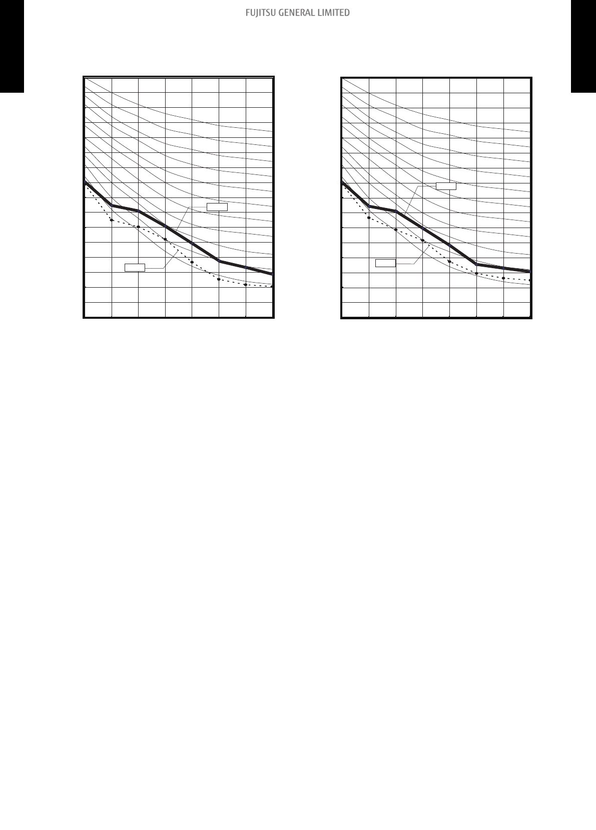
5-2. Fan performance curve
¢
Model: ADUH09LUAS1
Hi (SP mode 09)
Hi (Normal SP)
SP mode 09
upper limit
SP mode 09
lower limit
Quiet (SP mode 09)
Normal SP
upper limit
Quiet (Normal SP)
SP mode 00
upper limit
Quiet (SP mode 00)
0.44 (110)
0.40 (100)
0.36 (90)
0.32 (80)
0.28 (70)
0.24 (60)
0.20 (50)
0.16 (40)
0.12 (30)
0.08 (20)
0.04 (10)
0 (0)
177
235
294
353
412
(300)
(400)
(500)
(600)
(700)
External static pressure (inWG [Pa])
Airflow (CFM [m
3
/h])
471
(800)
*1
0.44 (110)
0.40 (100)
0.36 (90)
0.32 (80)
0.28 (70)
0.24 (60)
0.20 (50)
0.16 (40)
0.12 (30)
0.08 (20)
0.04 (10)
0 (0)
177
(300)
External static pressure (inWG [Pa])
Airflow (CFM [m
3
/h])
Hi (SP mode 09)
Hi (SP mode 08)
Hi (SP mode 07)
Hi (SP mode 06)
Hi (SP mode 05)
Hi (SP mode 04)
Hi (SP mode 03)
Hi (Normal SP)
Hi (SP mode 02)
Hi (SP mode 01)
Hi (SP mode 00)
Available airflow rate range (High level)
*1
235
294
353
471
(400)
(500)
(600)
(800)
412
(700)
*1: Available airflow rate range when Auto louver grille (option) is installed.
Fan speed : HIGH
Vertical airflow direction louver : Up
- 19 -
5-2. Fan performance curve 5. Fan performance
DUCT TYPE
ADUH09-18LUAS1
DUCT TYPE
ADUH09-18LUAS1

Characteristics of air volume and capacity
• Cooling
0
20
40
60
80
100
120
235
294
353
471
(400)
(500)
(600)
(800)
412
(700)
Capacity
Capacity (%)
Airflow (CFM [m
3
/h])
• Heating
0
20
40
60
80
100
120
235
294
353
471
(400)
(500)
(600)
(800)
412
(700)
Capacity
Capacity (%)
Airflow (CFM [m
3
/h])
- 20 -
5-2. Fan performance curve 5. Fan performance
DUCT TYPE
ADUH09-18LUAS1
DUCT TYPE
ADUH09-18LUAS1

¢
Model: ADUH12LUAS1
Hi (SP mode 09)
Hi (Normal SP)
SP mode 09
upper limit
SP mode 09
lower limit
Quiet (SP mode 09)
Normal SP
upper limit
Quiet (Normal SP)
SP mode 00
upper limit
Quiet (SP mode 00)
0.44 (110)
0.40 (100)
0.36 (90)
0.32 (80)
0.28 (70)
0.24 (60)
0.20 (50)
0.16 (40)
0.12 (30)
0.08 (20)
0.04 (10)
0 (0)
177
235
294
353
412
(300)
(400)
(500)
(600)
(700)
External static pressure (inWG [Pa])
Airflow (CFM [m
3
/h])
471
(800)
Hi (SP mode 00)
0.44 (110)
0.40 (100)
0.36 (90)
0.32 (80)
0.28 (70)
0.24 (60)
0.20 (50)
0.16 (40)
0.12 (30)
0.08 (20)
0.04 (10)
0 (0)
177
235
294
353
471
(300)
(400)
(500)
(600)
(800)
External static pressure (inWG [Pa])
Airflow (CFM [m
3
/h])
Hi (SP mode 09)
Hi (SP mode 08)
Hi (SP mode 07)
Hi (SP mode 06)
Hi (SP mode 05)
Hi (SP mode 04)
Hi (SP mode 03)
Hi (Normal SP)
Hi (SP mode 02)
Hi (SP mode 01)
Hi (SP mode 00)
Available airflow rate range (High level)
*1
412
(700)
*1: Available airflow rate range when Auto louver grille (option) is installed.
Fan speed : HIGH
Vertical airflow direction louver : Up
- 21 -
5-2. Fan performance curve 5. Fan performance
DUCT TYPE
ADUH09-18LUAS1
DUCT TYPE
ADUH09-18LUAS1

Characteristics of air volume and capacity
• Cooling
0
20
40
60
80
100
120
530
294
353
471
(900)
(500)
(600)
(800)
412
(700)
Capacity
Capacity (%)
Airflow (CFM [m
3
/h])
• Heating
(900)
0
20
40
60
80
100
120
530
294
353
471
(500)
(600)
(800)
412
(700)
Capacity
Capacity (%)
Airflow (CFM [m
3
/h])
- 22 -
5-2. Fan performance curve 5. Fan performance
DUCT TYPE
ADUH09-18LUAS1
DUCT TYPE
ADUH09-18LUAS1

¢
Model: ADUH18LUAS1
Hi (SP mode 09)
Hi (Normal SP)
SP mode 09
upper limit
SP mode 09
lower limit
Quiet (SP mode 09)
Normal SP
upper limit
Quiet (Normal SP)
SP mode 00
upper limit
Quiet (SP mode 00)
0.44 (110)
0.40 (100)
0.36 (90)
0.32 (80)
0.28 (70)
0.24 (60)
0.20 (50)
0.16 (40)
0.12 (30)
0.08 (20)
0.04 (10)
0 (0)
412
(700)
External static pressure (in.WG [Pa])
Airflow (CFM [m
3
/h])
Hi (SP mode 00)
530
589
647
706
(900)
(1,000)
(1,100)
(1,200)
471
(800)
353
(600)
0.44 (110)
0.40 (100)
0.36 (90)
0.32 (80)
0.28 (70)
0.24 (60)
0.20 (50)
0.16 (40)
0.12 (30)
0.08 (20)
0.04 (10)
0 (0)
External static pressure (inWG [Pa])
Airflow (CFM [m
3
/h])
Hi (SP mode 09)
Hi (SP mode 08)
Hi (SP mode 07)
Hi (SP mode 06)
Hi (SP mode 05)
Hi (SP mode 04)
Hi (SP mode 03)
Hi (Normal SP)
Hi (SP mode 02)
Hi (SP mode 01)
Hi (SP mode 00)
Available airflow rate range (High level)
*1
412
(700)
530
589
647
706
(900)
(1,000)
(1,100)
(1,200)
471
(800)
353
(600)
*1: Available airflow rate range when Auto louver grille (option) is installed.
Fan speed : HIGH
Vertical airflow direction louver : Up
- 23 -
5-2. Fan performance curve 5. Fan performance
DUCT TYPE
ADUH09-18LUAS1
DUCT TYPE
ADUH09-18LUAS1

Characteristics of air volume and capacity
• Cooling
0
20
40
60
80
100
120
Capacity
Capacity (%)
Airflow (CFM [m
3
/h])
412
(700)
530
589
647
(900)
(1,000)
(1,100)
471
(800)
• Heating
0
20
40
60
80
100
120
Capacity
Capacity (%)
Airflow (CFM [m
3
/h])
412
(700)
530
589
647
(900)
(1,000)
(1,100)
471
(800)
- 24 -
5-2. Fan performance curve 5. Fan performance
DUCT TYPE
ADUH09-18LUAS1
DUCT TYPE
ADUH09-18LUAS1

5-3. Airflow
Conversion factor:
• 1 m
3
/h = 0.2778 l/s = 0.5886 CFM
• 3.6 m
3
/h = 1 l/s
• 1.699 m
3
/h = 1 CFM
¢
Model: ADUH09LUAS1
Cooling
Fan speed Airflow
HIGH
m
3
/h
600
l/s 167
CFM 353
MED
m
3
/h
550
l/s 153
CFM 324
LOW
m
3
/h
500
l/s 139
CFM 294
QUIET
m
3
/h
450
l/s 125
CFM 265
Heating
Fan speed Airflow
HIGH
m
3
/h
600
l/s 167
CFM 353
MED
m
3
/h
550
l/s 153
CFM 324
LOW
m
3
/h
500
l/s 139
CFM 294
QUIET
m
3
/h
450
l/s 125
CFM 265
- 25 -
5-3. Airflow 5. Fan performance
DUCT TYPE
ADUH09-18LUAS1
DUCT TYPE
ADUH09-18LUAS1

¢
Model: ADUH12LUAS1
Cooling
Fan speed Airflow
HIGH
m
3
/h
650
l/s 181
CFM 382
MED
m
3
/h
600
l/s 167
CFM 353
LOW
m
3
/h
550
l/s 153
CFM 324
QUIET
m
3
/h
480
l/s 133
CFM 283
Heating
Fan speed Airflow
HIGH
m
3
/h
650
l/s 181
CFM 382
MED
m
3
/h
600
l/s 167
CFM 353
LOW
m
3
/h
550
l/s 153
CFM 324
QUIET
m
3
/h
480
l/s 133
CFM 283
- 26 -
5-3. Airflow 5. Fan performance
DUCT TYPE
ADUH09-18LUAS1
DUCT TYPE
ADUH09-18LUAS1

¢
ADUH18LUAS1
Cooling
Fan speed Airflow
HIGH
m
3
/h
940
l/s 261
CFM 553
MED
m
3
/h
880
l/s 244
CFM 518
LOW
m
3
/h
820
l/s 228
CFM 482
QUIET
m
3
/h
750
l/s 208
CFM 441
Heating
Fan speed Airflow
HIGH
m
3
/h
940
l/s 261
CFM 553
MED
m
3
/h
880
l/s 244
CFM 518
LOW
m
3
/h
820
l/s 228
CFM 482
QUIET
m
3
/h
750
l/s 208
CFM 441
- 27 -
5-3. Airflow 5. Fan performance
DUCT TYPE
ADUH09-18LUAS1
DUCT TYPE
ADUH09-18LUAS1

6. Operation noise (sound pressure)
6-1. Noise level curve
¢ Model: ADUH09LUAS1
Cooling
NC-65
NC-60
NC-55
NC-50
NC-45
NC-40
NC-35
NC-30
NC-25
NC-20
NC-15
Octave band sound pressure level, dB: (0 dB=0.0002 µbar)
Octave band center frequency, Hz
80
70
60
50
40
30
20
10
0
63
125 250 500 1,000 2,000 4,000
8,000
QUIET
HIGH
Heating
NC-65
NC-60
NC-55
NC-50
NC-45
NC-40
NC-35
NC-30
NC-25
NC-20
NC-15
Octave band sound pressure level, dB: (0 dB=0.0002 µbar)
Octave band center frequency, Hz
80
70
60
50
40
30
20
10
0
63
125 250 500 1,000 2,000 4,000
8,000
HIGH
QUIET
¢ Model: ADUH12LUAS1
Cooling
NC-65
NC-60
NC-55
NC-50
NC-45
NC-40
NC-35
NC-30
NC-25
NC-20
NC-15
Octave band sound pressure level, dB: (0 dB=0.0002 µbar)
Octave band center frequency, Hz
80
70
60
50
40
30
20
10
0
63
125 250 500 1,000 2,000 4,000
8,000
QUIET
HIGH
Heating
NC-65
NC-60
NC-55
NC-50
NC-45
NC-40
NC-35
NC-30
NC-25
NC-20
NC-15
Octave band sound pressure level, dB: (0 dB=0.0002 µbar)
Octave band center frequency, Hz
80
70
60
50
40
30
20
10
0
63
125 250 500 1,000 2,000 4,000
8,000
HIGH
QUIET
- 28 -
6-1. Noise level curve 6. Operation noise (sound pressure)
DUCT TYPE
ADUH09-18LUAS1
DUCT TYPE
ADUH09-18LUAS1
¢ Model: ADUH18LUAS1
Cooling
NC-65
NC-60
NC-55
NC-50
NC-45
NC-40
NC-35
NC-30
NC-25
NC-20
NC-15
Octave band sound pressure level, dB: (0 dB=0.0002 µbar)
Octave band center frequency, Hz
80
70
60
50
40
30
20
10
0
63
125 250 500 1,000 2,000 4,000
8,000
HIGH
QUIET
Heating
NC-65
NC-60
NC-55
NC-50
NC-45
NC-40
NC-35
NC-30
NC-25
NC-20
NC-15
Octave band sound pressure level, dB: (0 dB=0.0002 µbar)
Octave band center frequency, Hz
80
70
60
50
40
30
20
10
0
63
125 250 500 1,000 2,000 4,000
8,000
HIGH
QUIET
- 29 -
6-1. Noise level curve 6. Operation noise (sound pressure)
DUCT TYPE
ADUH09-18LUAS1
DUCT TYPE
ADUH09-18LUAS1

6-2. Sound level check point
Side view
60 in (1.5 m)
79 in (2 m)
Air
Product
40 in (1 m)
Microphone
Measuring duct Measuring duct
Front view
Microphone
(Set the static pressure
as rating in this area)
- 30 -
6-2. Sound level check point 6. Operation noise (sound pressure)
DUCT TYPE
ADUH09-18LUAS1
DUCT TYPE
ADUH09-18LUAS1

7. Safety devices
Type of protection Protection form
Model
ADUH09LUAS1
ADUH12LUAS1
ADUH18LUAS1
Circuit protection Current fuse (PCB*) 250 V, 5 A
Fan motor protection
Thermal protection program
Activate
275±27 °F (135±15 °C)
Fan motor stop
Reset
239±27 °F (115±15 °C)
Fan motor restart
Current protection 1.31—1.71 A
*: Printed Circuit Board
- 31 -
7. Safety devices
DUCT TYPE
ADUH09-18LUAS1
DUCT TYPE
ADUH09-18LUAS1
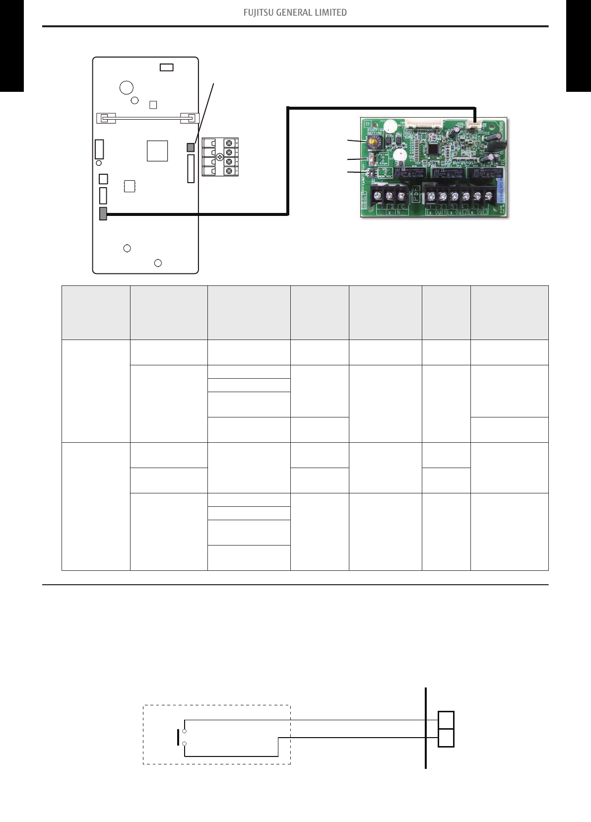
8. External input and output
Rotary switch
SW2
SW1
Fig. External input and output PCB
CN47 (Ext. out)
Terminal (Ext. in)
Indoor unit PCB
CN65
PCB External input External output Connector Input select
Input
signal
External
connect kit
(Optional
parts)
Indoor unit
Operation/Stop
Forced stop
— Terminal Dry contact Edge —
—
Operation status
CN47
— —
UTY-XWZXZG
Error status
Indoor unit fan
operation status
External heater
output
CN47
External input
and output
(UTY-XCSX)
Operation/Stop
—
Input 1/
Input 2
Dry contact/
Apply voltage
Edge/
Pulse
—
Forced
thermostat off
Input 1 Edge
—
Operation status
Output 1
Output 2
Output 3
— — —
Error status
Indoor unit fan
operation status
External heater
output
8-1. External input
• “Operation/Stop” mode or "Forced stop" mode can be selected with function setting of indoor unit.
• A twisted pair cable (22AWG) should be used. Maximum length of cable is 492 ft (150 m).
• The wire connection should be separate from the power cable line.
Indoor unit functions such as Operation/Stop can be done by using indoor unit terminals.
1
2
Terminal
*1: The switch can be used on the following condition: DC 12 V to 24 V, 1 mA to 15 mA.
- 32 -
8-1. External input 8. External input and output
DUCT TYPE
ADUH09-18LUAS1
DUCT TYPE
ADUH09-18LUAS1

¢
External input and output PCB
The indoor unit Operation/Stop can be set by using the input terminal on the PCB.
Input select
Use either one of these types of terminals according to the application. (Both types of terminals
cannot be used simultaneously.)
• Dry contact
In case of internal power supply, set the slide switch of SW1 to "NON VOL" side.
1
2
C
Input 1 Input 2
PCB
Connected unit
+
+
-
*1: The switches can be used on the following condition: DC 12 V to 24 V, 1 mA to 15 mA.
• Apply voltage
In case of external power supply, set the slide switch of SW1 to "VOL" side.
1
2
C
Input 1 Input 2 Power supply
PCB
Connected unit
+-
*1: The switches can be used on the following condition: DC 12 V to 24 V, 1 mA to 15 mA.
*2: Make the power supply DC 12 V to 24 V 10 mA or more.
- 33 -
8-1. External input 8. External input and output
DUCT TYPE
ADUH09-18LUAS1
DUCT TYPE
ADUH09-18LUAS1

8-2. External output
Use an external output cable with appropriate external dimension, depending on the number of ca-
bles to be installed.
• A twisted pair cable (22AWG) should be used. Maximum length of cable is 82 ft (25 m).
• Output voltage: High DC 12 V ± 2 V, Low 0 V.
• Permissible current: 50 mA
• For details, refer to "Combination of external input and output" on page 36.
When indicator, etc. are connected directly
Example: Function setting 60 is set to "00"
1
2
CN47
LED
PCB
Resistor
Connected unit
+
-
When connecting with a device equipped with a power supply
Example:
Function setting 60 is set to "00"
1
2
Connected device
CN47
PCB
Connected unit Relay
(Operation status)
-
+
- 34 -
8-2. External output 8. External input and output
DUCT TYPE
ADUH09-18LUAS1
DUCT TYPE
ADUH09-18LUAS1

¢
External input and output PCB
• A twisted pair cable (22AWG) should be used.
• Permissible voltage and current: DC 5 V to 30 V / 3 A, AC 30 V to 250 V / 3 A
• For details, refer to Chapter 8-3. "Combination of external input and output" on page 36.
1
2
3
4
5
6
Power supply
Power supply
Power supply
PCB
Connected device 1
(Operation status)
Connected device 2
(Error status)
(Indoor unit fan
operation status)
Connected device 3
Example
- 35 -
8-2. External output 8. External input and output
DUCT TYPE
ADUH09-18LUAS1
DUCT TYPE
ADUH09-18LUAS1

8-3. Combination of external input and output
By combining the function setting of the indoor unit and rotary switch setting of the External input
and output PCB, you can select various combinations of functions.
Combination examples of external input and output are as follows:
Mode
Function
setting
External input
and output
PCB (Rotary
SW)
External input
Indoor unit
Input
External input and output PCB
Terminal Input 1 Input 2 Signal type
0-1 60-00 1
Operation/Stop
(Function setting
46-00)
or
Forced stop
(Function setting
46-02)
Operation/Stop Not available Edge
Operation Stop Pulse
0-2 60-00 2
Forced
Thermostat OFF
Not available Edge
1 60-01 3
Mechanical
cooling Off
2 60-02 4
Forced
thermostat Off
3 60-03 5
Mechanical
cooling On
4 60-04 6
Mechanical
cooling On
5 60-05 7
Forced
thermostat Off
6 60-06 8
Forced
thermostat Off
7 60-07 9
Mechanical
cooling Off
8 60-08 A
Forced
thermostat Off
9 60-09 B
Forced
Thermostat OFF
10 60-10 C
Forced
Thermostat OFF
11 60-11 D
Forced
Thermostat OFF
12 60-12 D
Forced
Thermostat OFF
- 36 -
8-3. Combination of external input and output 8. External input and output
DUCT TYPE
ADUH09-18LUAS1
DUCT TYPE
ADUH09-18LUAS1

Mode
Function
setting
External input
and output
PCB (Rotary
SW)
External output
Indoor unit
Output
External input and output PCB
CN47 Output 1 Output 2 Output 3
0-1 60-00 1 Operation/Stop Operation/Stop Error status
Indoor unit fan
operation status
0-2 60-00 2 Operation/Stop Error status
Indoor unit fan
operation status
External heater
output
1 60-01 3
Cooling
thermostat On
Error status
Indoor unit fan
operation status
External heater
output
2 60-02 4
Cooling
thermostat On
Error status
Remote
controller output
External heater
output
3 60-03 5
Cooling
thermostat On
Cooling high/low
output
Remote
controller output
External heater
output
4 60-04 6
Cooling
thermostat On
Error status
Remote
controller output
Cooling high/low
output
5 60-05 7
Heating
thermostat On
Error status
Indoor unit fan
operation status
External heater
output
6 60-06 8 Operation/Stop Error status
Indoor unit fan
operation status
Heating
thermostat On
7 60-07 9
Cooling
thermostat On
Error status
Heating
thermostat On
External heater
output
8 60-08 A
Cooling
thermostat On
Heating
thermostat On
Remote
controller output
External heater
output
9 60-09 B Error status Operation/Stop
Indoor unit fan
operation status
External heater
output
10 60-10 C
Indoor unit fan
operation status
Operation/Stop Error status
External heater
output
11 60-11 D
External heater
output
Operation/Stop
Indoor unit fan
operation status
Error status
12 60-12 D
Set point
attainment status
Operation/Stop
Indoor unit fan
operation status
Error status
NOTE: Input of Operation/Stop depends on the setting of function setting 46.
00: Operation/Stop mode 1 (R.C. enabled)
01: (Setting prohibited)
02: Forced stop
03: Operation/Stop mode 2 (R.C. disabled)
- 37 -
8-3. Combination of external input and output 8. External input and output
DUCT TYPE
ADUH09-18LUAS1
DUCT TYPE
ADUH09-18LUAS1

¢
Input signal type
• Indoor unit
Input signal type is only "Edge".
Edge
• External input and output PCB
The input signal type can be selected.
Signal type (edge or pulse) can be switched by the DIP switch 2 (SW2) on the External input and
output PCB.
Edge
Pulse
The width of pulse must be
longer than 200 msec.
- 38 -
8-3. Combination of external input and output 8. External input and output
DUCT TYPE
ADUH09-18LUAS1
DUCT TYPE
ADUH09-18LUAS1

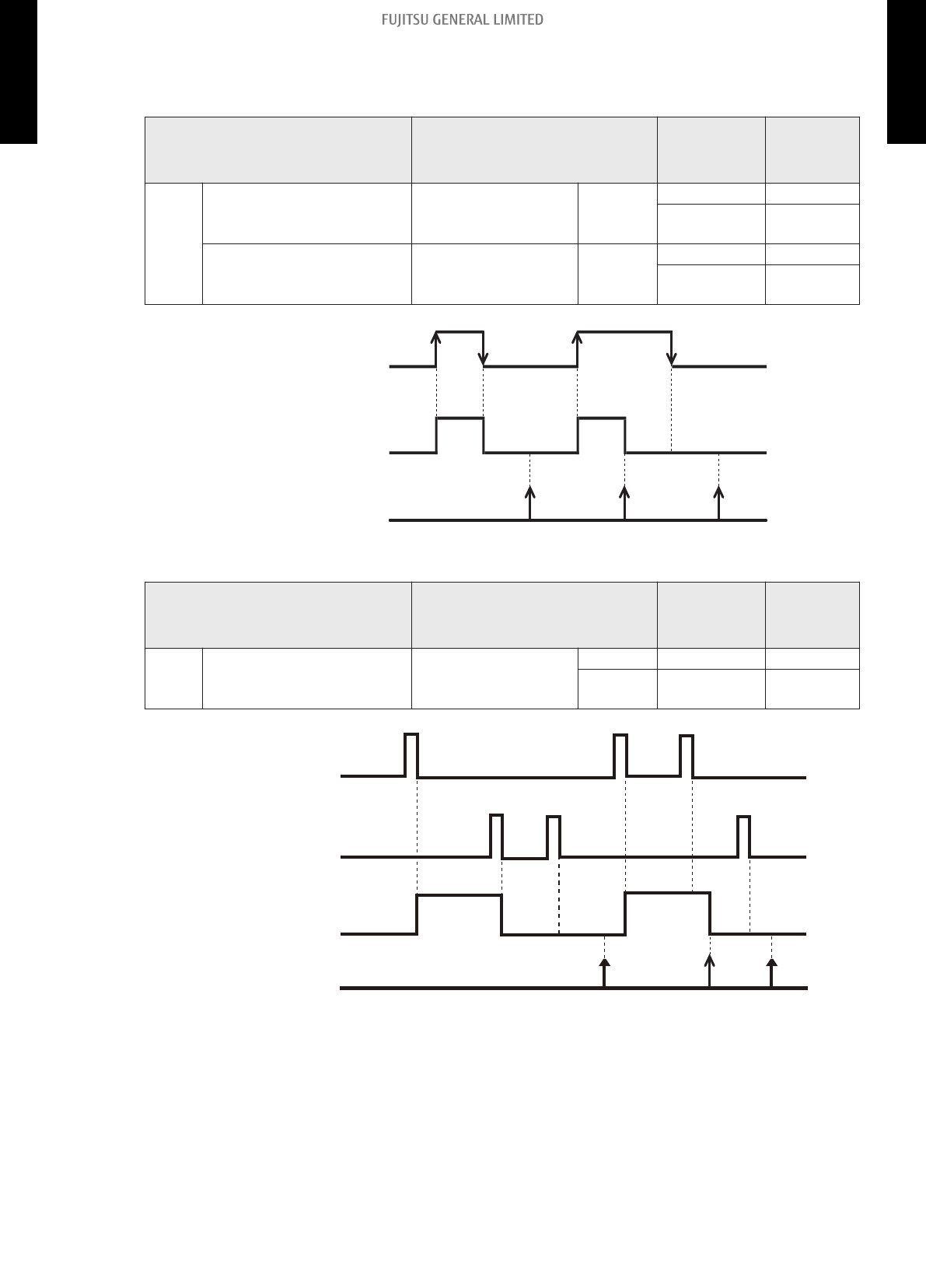
8-4. Details of function
¢
Control input function
When function setting is "Operation/Stop" mode 1
• In the case of "Edge" input
Function
setting /
Rotary SW of
External input and
output PCB
External input Input signal Command
46-00
- Input of indoor unit Terminal
Off → On Operation
On → Off Stop
60-00 / 1
External input and
output PCB
Input 1
Off → On Operation
On → Off Stop
Operation
Stop
Remote controller
On
Off
Indoor unit
On
Input
• In the case of "Pulse" input
Function
setting /
Rotary SW of
External input and
output PCB
External input Input signal Command
46-00 60-00 / 1
External input and
output PCB
Input 1 Pulse Operation
Input 2 Pulse Stop
On
On
Off
Operation
Stop
Remote controller
On
Off
Indoor unit
Input 1
Input 2
NOTES:
• The last command has priority.
• The indoor units within the same remote controller group operates in the same mode.
- 39 -
8-4. Details of function 8. External input and output
DUCT TYPE
ADUH09-18LUAS1
DUCT TYPE
ADUH09-18LUAS1

When function setting is "Forced stop" mode
• In the case of "Edge" input
Function
setting /
Rotary SW of
External input and
output PCB
External input Input signal Command
46-02
- Input of indoor unit Terminal
Off → On Forced stop
On → Off Normal
60-00 / 1
External input and
output PCB
Input 1
Off → On Forced stop
On → Off Normal
On
Off
Forced stop
Normal
Operation
Stop
Remote controller
On On
Indoor unit
On
Input
• In the case of "Pulse" input
Function
setting /
Rotary SW of
External input and
output PCB
External input Input signal Command
46-02 60-00 / 1
External input and
output PCB
Input 1 Pulse Forced stop
Input 2 Pulse Normal
On
Off
Operation
Stop
Remote controller
On
Off
Forced stop
Normal
Input 1
Input 2
On On On
Indoor unit
NOTES:
• When the forced stop is triggered, indoor unit stops and Operation/Stop operation by the re-
mote controller is restricted.
• When forced stop function is used with forming a remote controller group, connect the same
equipment to each indoor unit within the group.
- 40 -
8-4. Details of function 8. External input and output
DUCT TYPE
ADUH09-18LUAS1
DUCT TYPE
ADUH09-18LUAS1
When function setting is "Operation/Stop" mode 2
• In the case of "Edge" input
Function
setting /
Rotary SW of
External input and
output PCB
External input Input signal Command
46-03
- Input of indoor unit Terminal
Off → On Operation
On → Off
Stop (R.C.
disabled)
60-00 / 1
External input and
output PCB
Input 1
Off → On Operation
On → Off
Stop (R.C.
disabled)
On
Input
Off
Operation
Indoor unit
Stop
(R.C. disabled)
Remote controller
On OnOff
• In the case of "Pulse" input
Function
setting /
Rotary SW of
External input and
output PCB
External input Input signal Command
46-03 60-00 / 1
External input and
output PCB
Input 1 Pulse Operation
Input 2 Pulse
Stop (R.C.
disabled)
On
On
Off
Operation
Stop
Remote controller
On
Off
Indoor unit
Input 1
Input 2
(R.C. disabled)
Off
On
NOTES:
• When "Operation/Stop" mode 2 function is used with forming a remote controller group,
connect the same equipment to each indoor unit within the group.
- 41 -
8-4. Details of function 8. External input and output
DUCT TYPE
ADUH09-18LUAS1
DUCT TYPE
ADUH09-18LUAS1

¢
Forced thermostat off function
Function
setting /
Rotary SW of External
input and output PCB
External input Input signal Command
60-00 / 2
External input and output
PCB
Input 1
Off → On Thermostat off
60-02 / 4
60-05 / 7
60-06 / 8
60-08 / A
60-09 / B
60-10 / C
On → Off
Normal
operation
60-11 / D
On
Off
On
Off
Compressor
Room temp.
Set temp.
Input
¢
Control output function
Function
setting /
Rotary SW of External
input and output PCB
External output Output signal Command
60-00 / 1, 2
60-06 / 8
Output of indoor unit CN47
Low → High Operation
High → Low Stop
60-00 / 1
External input and output
PCB
Output 1
Off → On Operation
60-09 / B
60-10 / C
On → Off Stop
60-11 / D
The output is low when the unit is stopped.
Operation
Stop
High
Low
CN47
On
Off
Output 1
Indoor unit
- 42 -
8-4. Details of function 8. External input and output
DUCT TYPE
ADUH09-18LUAS1
DUCT TYPE
ADUH09-18LUAS1

¢
Error status
Function
setting /
Rotary SW of External
input and output PCB
External output Output signal Command
60-09 / B Output of indoor unit CN47
Low → High Error
High → Low Normal
60-00 / 2
60-01 / 3
60-02 / 4
60-04 / 6
60-05 / 7
60-06 / 8
60-07 / 9
External input and output
PCB
Output 1
Off → On Error
On → Off Normal
60-00 / 1
Output 2
Off → On Error
60-10 / C
On → Off Normal
60-11 / D Output 3
Off → On Error
On → Off Normal
The output is ON when an error is generated for the indoor unit.
Error
Normal
High
Low
CN47
On
Off
Output 1, 2, 3
Indoor unit
- 43 -
8-4. Details of function 8. External input and output
DUCT TYPE
ADUH09-18LUAS1
DUCT TYPE
ADUH09-18LUAS1

¢
Indoor unit fan operation status
Function
setting /
Rotary SW of External
input and output PCB
External output Output signal Command
60-10 / C Output of indoor unit CN47
Low → High Fan run
High → Low Fan stop
60-00 / 2
60-01 / 3
60-05 / 7
60-06 / 8
60-09 / B
60-11 / D
External input and output
PCB
Output 2
Off → On Fan run
On → Off Fan stop
60-00 / 1 Output 3
Off → On Fan run
On → Off Fan stop
Output signal Condition
On
The indoor unit fan is operating.
Low → High
Off The fan is stopped or during cold air prevention.
High → Low During thermostat off when in dry mode operation.
Fan run
Fan stop
High
Low
CN47
On
Off
Output 2, 3
Indoor unit
- 44 -
8-4. Details of function 8. External input and output
DUCT TYPE
ADUH09-18LUAS1
DUCT TYPE
ADUH09-18LUAS1

¢
External heater output
Control Primary heater Auxiliary heater
Function setting
Indoor unit
Control switching
external heaters No. 61
Auxiliary heater control 1 Heat pump
External device*
1
61-00
Auxiliary heater control 2 Heat pump External device 61-01
Heat pump prohibition
control
External device None 61-02
Auxiliary heater control by
outdoor temperature 1
Heat pump External device 61-03
Auxiliary heater control by
outdoor temperature 2
Heat Pump External device 61-04
Auxiliary heater control by
outdoor temperature 3
Heat Pump External device 61-05
Auxiliary heat pump
control
External device Heat pump 61-06
Auxiliary heat pump
control by outdoor
temperature 1
External device Heat pump 61-07
Auxiliary heat pump
control by outdoor
temperature 2
External device Heat pump 61-08
Auxiliary heat pump
control by outdoor
temperature 3
External device Heat pump 61-09
NOTES:
• After turning off the heater, 3 minutes of standby time is required by next power-on of the
heater.
• For items marked “—” in the table, any of validate or invalidate of the setting are acceptable.
• *1: External device means Hot water, Electrical heater, etc.
- 45 -
8-4. Details of function 8. External input and output
DUCT TYPE
ADUH09-18LUAS1
DUCT TYPE
ADUH09-18LUAS1

Installation configuration of individual connection
External heating device is installed individually. (No use of indoor unit fan)
Example of heating device:
- Floor heating device
On/Off
WARNING
• DIP Switch 101-3 must be in the ON position when ducted electric heat application is be-
ing used. DIP switch 101-3 is set in the ON position by default from the factory. When DIP
switch 101-3 is in the ON position and ducted electric heat application is not being used, cold
draft occurs due to fan delay off operation.
Operation Condition
Heater off
DIP-SW101-3 On • Heater is off as shown in following diagram of heating
temperature.
• Other than heating mode
• Error occurred
• Forced thermostat off
• Fan stop protection
Indoor unit fan
setting for
external heater
Enabled
DIP-SW101-3 Off • Heater is off as shown in following diagram of heating
temperature.
• Other than heating mode
• Error occurred
• Forced thermostat off
Indoor unit fan
setting for
external heater
Disabled
SW101
CN47
CN65
• Design and install external heater appropriately with considering its protection.
External
heater
Indoor
unit
Supply air Return air
• Inappropriate designing and installation of external heater may cause a fire by emitted heat from
the external heater.
• Fujitsu General Ltd. is not responsible for inappropriate designing or installation of external heat-
ing device.
- 46 -
8-4. Details of function 8. External input and output
DUCT TYPE
ADUH09-18LUAS1
DUCT TYPE
ADUH09-18LUAS1

Auxiliary equipment control by room temperature
Auxiliary equipment control is switchable by room temperature. Auxiliary equipment switching is per-
formed for each room temperature divided to following 3 zones.
Tr
Ts +0.9°F (0.5 °C)
Ts -0.9°F (0.5 °C)
Ts
Zone C
Zone A
Zone B
Ts: Setting temperature
Tr: Room temperature
Zone Application
When temperature dropping When temperature rising
Primary Auxiliary Primary Auxiliary
A
Both of primary and auxiliary equipment
is unnecessary.
Off Off Off Off
B
Primary heater only.When room
temperature stays in zone B for a long
time, auxiliary equipment also operates.
On
Off*
1
— —
C Auxiliary equipment also operates. On
On*
2
On
On*
2
*1: For standby time for auxiliary equipment operation, refer to indoor unit function number 71 "Con-
tents of function setting" on page 66.
*2: When indoor unit function number 61 is set to "00", auxiliary equipment operates according to the
following conditions.
• Ts - Tr > 21.6 °F (-12.0 °C): Auxiliary equipment turn off.
• Ts - Tr > 18.0 °F (-10.0 °C): Auxiliary equipment turn on.
- 47 -
8-4. Details of function 8. External input and output
DUCT TYPE
ADUH09-18LUAS1
DUCT TYPE
ADUH09-18LUAS1

Auxiliary heater control 1
Operation Condition
Heater on Heater is on as shown in following diagram of heating temperature.
Heater off
• Heater is off as shown in following diagram of heating temperature.
• Other than heating mode
• Error occurred
• Forced thermostat off
• Fan stop protection
• Temperature of heater on (Thon): Adjustable by function number 62 (Operating temperature
switching of external heaters).
• All control temperatures will shift by adjusting “Thon”.
Tr-Ts ≥ -1.8°F
(-1°C)
Tr-Ts
Tr-Ts (=Thon) < -5.4°F (-3°C)
Tr-Ts < -21.6°F
(-12°C)
Tr: Room temperature
Ts: Set temperature
Thon: Heater on temperature
Off
Off
On
*
A
Tr-Ts ≥ -18°F
(-10°C)
*: When room temperature stays in this zone for a specific time, auxiliary heater is turned on. For
details, refer to function number 71.
Example: When set temperature (Ts) is 72°F (22°C) (Factory setting),
• and room temperature (Tr) increases above 53.6°F (12°C), signal output is on.
• and room temperature (Tr) increases above 69.8°F (21°C), signal output is off.
• and room temperature (Tr) decreases below 66.2°F (19°C), signal output is on.
• and room temperature (Tr) decreases below 50°F (10°C), signal output is off.
Auxiliary heater control 2
Control that excludes “A” from "Auxiliary heater control 1" on page 48.
Operation Condition
Heater on Heater is on as shown in following diagram of heating temperature.
Heater off
• Heater is off as shown in following diagram of heating temperature.
• Other than heating mode
• Error occurred
• Forced thermostat off
• Fan stop protection
• Temperature of heater on (Thon): Adjustable by function number 62 (Operating temperature
switching of external heaters).
• All control temperatures will shift by adjusting “Thon”.
Tr-Ts
Tr: Room temperature
Ts: Set temperature
Thon: Heater on temperature
Off
On
*
Tr-Ts ≥ -1.8°F
(-1°C)
Tr-Ts (=Thon) < -5.4°F (-3°C)
*: When room temperature stays in this zone for a specific time, auxiliary heater is turned on. For
details, refer to function number 71.
- 48 -
8-4. Details of function 8. External input and output
DUCT TYPE
ADUH09-18LUAS1
DUCT TYPE
ADUH09-18LUAS1

Heat pump prohibition control
Perform heating by external heater only. Indoor unit is continuous thermostat off.
Operation Condition
Heater on
Heater is on as shown in following diagram of heating
temperature.
Heater off
DIP-SW101-3 On • Heater is off as shown in following diagram of heating
temperature.
• Other than heating mode
• Error occurred
• Forced thermostat off
• Fan stop protection
Indoor unit fan
setting for
external heater
Enabled
DIP-SW101-3 Off • Heater is off as shown in following diagram of heating
temperature.
• Other than heating mode
• Error occurred
• Forced thermostat off
Indoor unit fan
setting for
external heater
Disabled
• Temperature of heater on (Thon): Adjustable by function number 62 (Operating temperature
switching of external heaters).
• All control temperatures will shift by adjusting “Thon”.
Tr: Room temperature
Ts: Set temperature
Thon: Heater on temperature
Off
On
Tr-Ts
Tr-Ts (=Thon) ≤ -0.9°F (-0.5°C)
Tr-Ts ≥ 0.9°F
(0.5°C)
• Operation status
On
0.9°F (0.5°C)
-0.9°F (-0.5°C)
On
12 V
On
Off
Off
0 V
Off
Heating operation
Heater
Fan
Air conditioner
Room temperature
Set temp.
3 min or more
1 min 1 min
On
Off
DIP-SW101-3 On
DIP-SW101-3 Off
NOTE:
In following operations, compressor will be on.
• Other than heating
• Test run
- 49 -
8-4. Details of function 8. External input and output
DUCT TYPE
ADUH09-18LUAS1
DUCT TYPE
ADUH09-18LUAS1

Auxiliary heater control by outdoor temperature 1
This control selects heat pump or external heater according to the outdoor temperature. When out-
door temperature is high, the heating is performed by using heat pump only.
Operation Condition
Heater on
Heater is on as shown in following diagram of heating
temperature.
Heater off
DIP-SW101-3 On • Heater is off as shown in following diagram of heating
temperature.
• Other than heating mode
• Error occurred
• Forced thermostat off
• Heat pump only zone
• Fan stop protection
Indoor unit fan
setting for
external heater
Enabled
DIP-SW101-3 Off • Heater is off as shown in following diagram of heating
temperature.
• Other than heating mode
• Error occurred
• Forced thermostat off
• Heat pump only zone
Indoor unit fan
setting for
external heater
Disabled
• Temperature of heater on (Thon): Adjustable by function number 62 (Operating temperature
switching of external heaters).
• All control temperatures will shift by adjusting “Thon”.
• Outdoor temperature zone boundary A and B: Adjustable individually by function setting number
66 and 67.
• External heater output
Tr: Room temperature
Ts: Set temperature
Thon: Heater on temperature
Tr-Ts
Off
On
*
Tr-Ts ≥ 0.9°F
(0.5°C)
Tr-Ts (=Thon) < -0.9°F (-0.5°C)
*: When room temperature stays in this zone for a specific time, auxiliary heater is turned on. For
details, refer to function number 71.
• Outdoor temperature zone
Heat pump only zone
(Heat pump)
Combination zone
(Heat pump + Heater)
Heat pump prohibition zone
(Heater)
B: 42.8°F (6°C)*
A: -4°F (-20°C)*
B + 3.6°F (2°C): 46.4°F (8°C)
A + 3.6°F ( 2°C): -0.4°F (-18°C)
Outdoor temp.
*: Adjustable by function setting 66 and 67
- 50 -
8-4. Details of function 8. External input and output
DUCT TYPE
ADUH09-18LUAS1
DUCT TYPE
ADUH09-18LUAS1
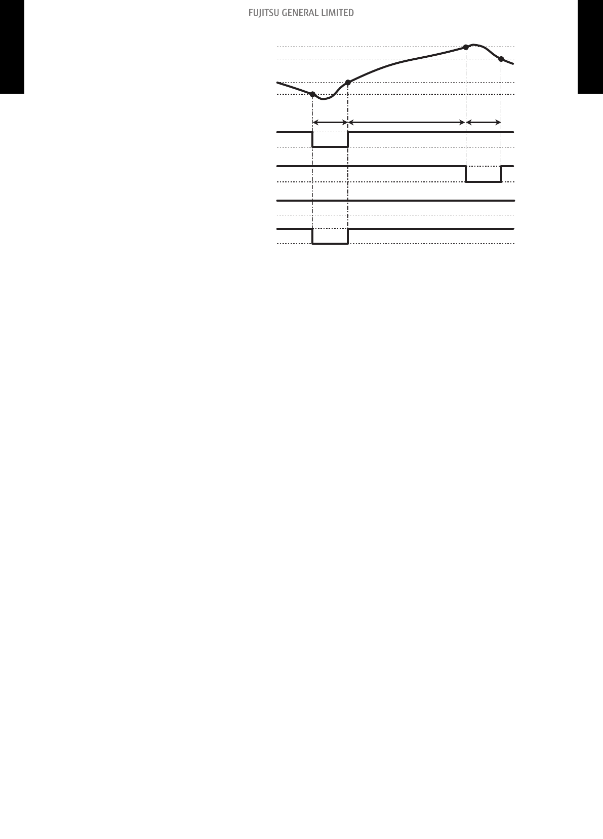
• Operation status
On
On
12 V
Off
Off
0 V
Heater
Comp. On/Off
Outdoor temperature
(Factory setting)
Outdoor temperature zone*
Heat pump
prohibition
zone
Heat pump
only zone
Combination zone
*: The outdoor temperature zone transition from one to another will stay in that zone for minimum of 30 min.
46.4°F (8°C)
42.8°F (6°C)
-0.4°F (-18°C)
-4°F (-20°C)
On
Off
Fan
DIP-SW101-3: On
DIP-SW101-3: Off
NOTE: In following operations, compressor will be on in heat pump prohibition zone.
• Other than heating
• Test run
- 51 -
8-4. Details of function 8. External input and output
DUCT TYPE
ADUH09-18LUAS1
DUCT TYPE
ADUH09-18LUAS1

Auxiliary heater control by outdoor temperature 2
This control selects heat pump or external heater according to the outdoor temperature. Even when
outdoor temperature is high, the heating is performed by using both of heat pump and external
heater.
Operation Condition
Heater on Heater is on as shown in following diagram of heating temperature.
Heater off
DIP-SW101-3 On • Heater is off as shown in following diagram of heating temperature.
• Other than heating mode
• Error occurred
• Forced thermostat off
• Fan stop protection
Indoor unit fan
setting for
external heater
Enabled
DIP-SW101-3 Off • Heater is off as shown in following diagram of heating temperature.
• Other than heating mode
• Error occurred
• Forced thermostat off
Indoor unit fan
setting for
external heater
Disabled
• Temperature of heater on (Thon): Adjustable by function number 62 (Operating temperature
switching of external heaters).
• All control temperatures will shift by adjusting “Thon”.
• Outdoor temperature zone boundary A: Adjustable by function setting number 66.
• External heater output
Tr: Room temperature
Ts: Set temperature
Thon: Heater on temperature
Tr-Ts
Off
On
*
Tr-Ts ≥ 0.9°F
(0.5°C)
Tr-Ts (=Thon) < -0.9°F (-0.5°C)
*: When room temperature stays in this zone for a specific time, auxiliary heater is turned on. For
details, refer to function number 71.
• Outdoor temperature zone
Combination zone
(Heat pump + Heater)
Heat pump prohibition zone
(Heater)
A: -4°F (-20°C)*
A + 3.6°F ( 2°C): -0.4°F (-18°C)
Outdoor temp.
*: Adjustable by function setting 66
- 52 -
8-4. Details of function 8. External input and output
DUCT TYPE
ADUH09-18LUAS1
DUCT TYPE
ADUH09-18LUAS1

• Operation status
On
12 V
Off
0 V
Heater
Comp. On/Off
Outdoor temperature
(Factory setting)
Outdoor temperature zone *
Heat pump
prohibition
zone
Combination zone
* The outdoor temperature zone transition from one to another will stay in that zone for minimum of 30 min.
46.4°F (8°C)
42.8°F (6°C)
-0.4°F (-18°C)
-4°F (-20°C)
On
Off
On
Off
Fan
DIP-SW101-3 On
DIP-SW101-3 Off
NOTE:
In following operations, compressor will be on in heat pump prohibition zone.
• Other than heating
• Test run
- 53 -
8-4. Details of function 8. External input and output
DUCT TYPE
ADUH09-18LUAS1
DUCT TYPE
ADUH09-18LUAS1

Auxiliary heater control by outdoor temperature 3
This control selects heat pump or external heater according to the outdoor temperature. Even when
outdoor temperature is high, the heating is performed by using both of heat pump and external
heater.
Operation Condition
Heater on Heater is on as shown in following diagram of heating temperature.
Heater off
DIP-SW101-3 On • Heater is off as shown in following diagram of heating
temperature.
• Other than heating mode
• Error occurred
• Forced thermostat off
• Fan stop protection
Indoor unit fan
setting for
external heater
Enabled
DIP-SW101-3 Off • Heater is off as shown in following diagram of heating
temperature.
• Other than heating mode
• Error occurred
• Forced thermostat off
Indoor unit fan
setting for
external heater
Disabled
• Temperature of heater on (Thon): Adjustable by function number 62 (Operating temperature
switching of external heaters).
• All control temperatures will shift by adjusting “Thon”.
• Outdoor temperature zone boundary B: Adjustable by function setting number 67.
• External heater output
Tr: Room temperature
Ts: Set temperature
Thon: Heater on temperature
Tr-Ts
Off
On
*
Tr-Ts ≥ 0.9°F
(0.5°C)
Tr-Ts (=Thon) < -0.9°F (-0.5°C)
*: When room temperature stays in this zone for a specific time, auxiliary heater is turned on. For
details, refer to function number 71.
• Outdoor temperature zone
B: 42.8°F (6°C)*
B + 3.6°F (2°C): 46.4°F (8°C)
Outdoor temp.
Combination zone
(Heat pump + Heater)
Heat pump only zone
(Heat pump)
*: Adjustable by function setting 67
- 54 -
8-4. Details of function 8. External input and output
DUCT TYPE
ADUH09-18LUAS1
DUCT TYPE
ADUH09-18LUAS1

• Operation status
*: The outdoor temperature zone transition from one to another will stay in that zone for minimum of 30 min.
Combination zone
Heat pump only zone
On
12 V
Off
0 V
Heater
Comp. On/Off
Outdoor temperature
(Factory setting)
Outdoor temperature zone *
46.4°F (8°C)
42.8°F (6°C)
-0.4°F (-18°C)
-4°F (-20°C)
On
Off
On
Off
Fan
DIP-SW101-3 On
DIP-SW101-3 Off
NOTE: In following operations, compressor will be on in heat pump prohibition zone.
• Other than heating
• Test run
- 55 -
8-4. Details of function 8. External input and output
DUCT TYPE
ADUH09-18LUAS1
DUCT TYPE
ADUH09-18LUAS1

Auxiliary heat pump control
• External heater output
Operation Condition
Heater on
Heater is on as shown in following diagram of heating
temperature.
Heater off
DIP-SW101-3 On • Heater is off as shown in following diagram of heating
temperature.
• Other than heating mode
• Error occurred
• Forced thermostat off
• Fan stop protection
Indoor unit fan
setting for
external heater
Enabled
DIP-SW101-3 Off • Heater is off as shown in following diagram of heating
temperature.
• Other than heating mode
• Error occurred
• Forced thermostat off
Indoor unit fan
setting for
external heater
Disabled
– Temperature of heater on (Thon): Set temperature (Ts) - 0.9 °F (- 0.5 °C)
– Temperature of heater off: Set temperature (Ts) + 0.9 °F (+ 0.5 °C)
Tr: Room temperature
Ts: Set temperature
Thon: Heater on temperature
Off
On
Tr-Ts
Tr-Ts (=Thon) ≤ -0.9°F (-0.5°C)
Tr-Ts ≥ 0.9°F
(0.5°C)
• Auxiliary heat pump On/Off
– Temperature of heater on (Thon): Adjustable by function number 62 (Operating temperature
switching of heat pump).
– All control temperatures will shift by adjusting “Thon”.
Tr: Room temperature
Ts: Set temperature
Thon: Heater on temperature
Off
On
*
Tr-Ts
Tr-Ts ≥ -1.8°F
(-1°C)
Tr-Ts (=Thon) < -5.4°F (-3°C)
*: When room temperature stays in this zone for a specific time, auxiliary heater is turned on. For
details, refer to function number 71.
- 56 -
8-4. Details of function 8. External input and output
DUCT TYPE
ADUH09-18LUAS1
DUCT TYPE
ADUH09-18LUAS1

Auxiliary heat pump control by outdoor temperature 1
• External heater output
Operation Condition
Heater on Heater is on as shown in following diagram of heating temperature.
Heater off
DIP-SW101-3 On • Heater is off as shown in following diagram of heating
temperature.
• Other than heating mode
• Error occurred
• Forced thermostat off
• Fan stop protection
Indoor unit fan
setting for
external heater
Enabled
DIP-SW101-3 Off • Heater is off as shown in following diagram of heating
temperature.
• Other than heating mode
• Error occurred
• Forced thermostat off
Indoor unit fan
setting for
external heater
Disable
d
– Temperature of heater on (Thon): Set temperature (Ts) - 0.9 °F (- 0.5 °C)
– Temperature of heater off: Set temperature (Ts) + 0.9 °F (+ 0.5 °C)
Tr: Room temperature
Ts: Set temperature
Thon: Heater on temperature
Off
On
Tr-Ts
Tr-Ts (=Thon) ≤ -0.9°F (-0.5°C)
Tr-Ts ≥ 0.9°F
(0.5°C)
• Auxiliary heat pump On/Off
– Temperature of heater on (Thon): Adjustable by function number 62 (Operating temperature
switching of heat pump).
– All control temperatures will shift by adjusting “Thon”.
Tr: Room temperature
Ts: Set temperature
Thon: Heater on temperature
Off
On
*
Tr-Ts
Tr-Ts ≥ -1.8°F
(-1°C)
Tr-Ts (=Thon) < -5.4°F (-3°C)
*: When room temperature stays in this zone for a specific time, auxiliary heater is turned on. For
details, refer to function number 71.
- 57 -
8-4. Details of function 8. External input and output
DUCT TYPE
ADUH09-18LUAS1
DUCT TYPE
ADUH09-18LUAS1

• Outdoor temperature zone
Combination zone
(Heat pump + Heater)
Heater only zone
*A: -4°F (-20°C)
A + 3.6°F ( 2°C): -0.4°F (-18°C)
Outdoor temp.
*: Adjustable by function setting 67
• Operation status
On
12 V
Off
0 V
Heater
Comp. On/Off
Outdoor temperature
(Factory setting)
Outdoor temperature zone *
Heat pump
prohibition
zone
Combination zone
* The outdoor temperature zone transition from one to another will stay in that zone for minimum of 30 min.
46.4°F (8°C)
42.8°F (6°C)
-0.4°F (-18°C)
-4°F (-20°C)
On
Off
On
Off
Fan
DIP-SW101-3 On
DIP-SW101-3 Off
NOTE: In following operations, compressor will be on in heat pump prohibition zone.
• Other than heating
• Test run
- 58 -
8-4. Details of function 8. External input and output
DUCT TYPE
ADUH09-18LUAS1
DUCT TYPE
ADUH09-18LUAS1

Auxiliary heat pump control by outdoor temperature 2
• External heater output
Operation Condition
Heater on
Heater is on as shown in following diagram of heating
temperature.
Heater off
DIP-SW101-3 On • Heater is off as shown in following diagram of heating
temperature.
• Other than heating mode
• Error occurred
• Forced thermostat off
• Fan stop protection
Indoor unit fan
setting for
external heater
Enabled
DIP-SW101-3 Off • Heater is off as shown in following diagram of heating
temperature.
• Other than heating mode
• Error occurred
• Forced thermostat off
Indoor unit fan
setting for
external heater
Disabled
– Temperature of heater on (Thon): Set temperature (Ts) - 0.9 °F (- 0.5 °C)
– Temperature of heater off: Set temperature (Ts) + 0.9 °F (+ 0.5 °C)
Tr: Room temperature
Ts: Set temperature
Thon: Heater on temperature
Off
On
Tr-Ts
Tr-Ts (=Thon) ≤ -0.9°F (-0.5°C)
Tr-Ts ≥ 0.9°F
(0.5°C)
• Auxiliary heat pump On/Off
– Temperature of heater on (Thon): Adjustable by function number 62 (Operating temperature
switching of heat pump).
– All control temperatures will shift by adjusting “Thon”.
Tr: Room temperature
Ts: Set temperature
Thon: Heater on temperature
Off
On
*
Tr-Ts
Tr-Ts ≥ -1.8°F
(-1°C)
Tr-Ts (=Thon) < -5.4°F (-3°C)
*: When room temperature stays in this zone for a specific time, auxiliary heater is turned on. For
details, refer to function number 71.
- 59 -
8-4. Details of function 8. External input and output
DUCT TYPE
ADUH09-18LUAS1
DUCT TYPE
ADUH09-18LUAS1

• Outdoor temperature zone
*B: 42.8°F (6°C)
B + 3.6°F (2°C): 46.4°F (8°C)
Outdoor temp.
Combination zone
(Heat pump + Heater)
Heater only zone
*: Adjustable by function setting 67
• Operation status
*: The outdoor temperature zone transition from one to another will stay in that zone for minimum of 30 min.
Combination zone
Heat pump prohibition zone
On
12 V
Off
0 V
Heater
Comp. On/Off
Outdoor temperature
(Factory setting)
Outdoor temperature zone*
46.4°F (8°C)
42.8°F (6°C)
-0.4°F (-18°C)
-4°F (-20°C)
On
Off
On
Off
Fan
DIP-SW101-3 On
DIP-SW101-3 Off
NOTE: In following operations, compressor will be on in heat pump prohibition zone.
• Other than heating
• Test run
- 60 -
8-4. Details of function 8. External input and output
DUCT TYPE
ADUH09-18LUAS1
DUCT TYPE
ADUH09-18LUAS1

Auxiliary heat pump control by outdoor temperature 3
• External heater output
Operation Condition
Heater on
Heater is on as shown in following diagram of heating
temperature.
Heater off
DIP-SW101-3 On • Heater is off as shown in following diagram of heating
temperature.
• Other than heating mode
• Error occurred
• Forced thermostat off
• Fan stop protection
Indoor unit fan
setting for
external heater
Enabled
DIP-SW101-3 Off • Heater is off as shown in following diagram of heating
temperature.
• Other than heating mode
• Error occurred
• Forced thermostat off
Indoor unit fan
setting for
external heater
Disabled
– Temperature of heater on (Thon): Set temperature (Ts) - 0.9 °F (- 0.5 °C)
– Temperature of heater off: Set temperature (Ts) + 0.9 °F (+ 0.5 °C)
Tr: Room temperature
Ts: Set temperature
Thon: Heater on temperature
Off
On
Tr-Ts
Tr-Ts (=Thon) ≤ -0.9°F (-0.5°C)
Tr-Ts ≥ 0.9°F
(0.5°C)
• Auxiliary heat pump On/Off
– Temperature of heater on (Thon): Adjustable by function number 62 (Operating temperature
switching of heat pump).
– All control temperatures will shift by adjusting “Thon”.
Tr: Room temperature
Ts: Set temperature
Thon: Heater on temperature
Off
On
*
Tr-Ts
Tr-Ts ≥ -1.8°F
(-1°C)
Tr-Ts (=Thon) < -5.4°F (-3°C)
*: When room temperature stays in this zone for a specific time, auxiliary heater is turned on. For
details, refer to function number 71.
- 61 -
8-4. Details of function 8. External input and output
DUCT TYPE
ADUH09-18LUAS1
DUCT TYPE
ADUH09-18LUAS1

• Outdoor temperature zone
Heater only zone
Combination zone
(Heat pump + Heater)
Heater only zone
B: 42.8°F (6°C)*
A: -4°F (-20°C)*
B + 3.6°F (2°C): 46.4°F (8°C)
A + 3.6°F (2°C): -0.4°F (-18°C)
Outdoor temp.
*: Adjustable by function setting 66 and 67
• Operation status
On
12 V
Off
0 V
Heater
Comp. On/Off
Outdoor temperature
(Factory setting)
Outdoor temperature zone *
* The outdoor temperature zone transition from one to another will stay in that zone for minimum of 30 min.
46.4°F (8°C)
42.8°F (6°C)
-0.4°F (-18°C)
-4°F (-20°C)
Combination zone
Heat pump prohibition zone
On
Off
On
Off
Fan
DIP-SW101-3 On
DIP-SW101-3 Off
NOTE: In following operations, compressor will be on in heat pump prohibition zone.
• Other than heating
• Test run
- 62 -
8-4. Details of function 8. External input and output
DUCT TYPE
ADUH09-18LUAS1
DUCT TYPE
ADUH09-18LUAS1

¢
Heating thermostat on for humidifier
Situation
Indoor unit
Mode
Function
setting
Rotary SW
External output
Heating
thermostat on
no. 60
Heating
thermostat on
Indoor unit fan
operation
status
Example of
individual
connection
5 60-05 7 CN47
Not used
6 60-06 8 Output3
7 60-07 9 Output2
8 60-08 A Output1
• Example of individual connection
External output: Heating thermostat on
Humidifier
• Operation status
The heating thermostat output for CN47, Output1, Output2, and Output3 will be on when comp on
or external heater on.
The heating thermostat output will be off when comp off and external heater off.
Heating operation
Heating thermostat
On output
External heater
output On / Off
Comp. On / Off
On
On
On
On
On
Off
Off
Off
Off
Off
Fan
Cool air prevention
- 63 -
8-4. Details of function 8. External input and output
DUCT TYPE
ADUH09-18LUAS1
DUCT TYPE
ADUH09-18LUAS1

9. Function settings
To adjust the functions of this product according to the installation environment, various types of
function settings are available.
NOTE:
Incorrect settings can cause a product malfunction.
9-1. Function settings on indoor unit
By using some components on the PCB, you can change the function settings.
Related components on the PCB and the applicable settings:
Component Setting content
DIP switch SW101
1 Drainage function setting
2 Auto louver grille setting
3 Fan delay setting
¢ Component location
Components on the indoor unit main PCB used for the function settings are located as shown in
the following figure.
SW101
1
2
3
- 64 -
9-1. Function settings on indoor unit 9. Function settings
DUCT TYPE
ADUH09-18LUAS1
DUCT TYPE
ADUH09-18LUAS1

¢ DIP switch setting
• SW101-Switch 1: Drainage function setting
Switch 1 Drainage function Factory setting
ON Disabled
OFF Enabled ♦
• SW101-Switch 2: Auto louver grille setting
When Auto louver grille kit (optional parts) is attached, set to “Enabled”.
Switch 2 Auto louver grille setting Factory setting
ON Enabled
OFF Disabled ♦
• SW101-Switch 3: Fan delay setting
When the indoor unit is stopped while operating in conjunction with auxiliary heater, the indoor
unit fan operation will continue for 1 minute.
Switch 3 Fan delay Factory setting
ON Enabled
OFF Disabled ♦
- 65 -
9-1. Function settings on indoor unit 9. Function settings
DUCT TYPE
ADUH09-18LUAS1
DUCT TYPE
ADUH09-18LUAS1

9-2. Function settings by using remote controller
Some function settings can be changed on the remote controller. After confirming the setting proce-
dure and the content of each function setting, select appropriate functions for your installation envi-
ronment.
¢
Setting procedure by using remote controller
Remote controller is not attached for this product. For details of the installing remote controller, refer
to following information.
• Overview information: Operating manual of the remote controller
• Setting procedure: Installation manual of the remote controller
¢
Contents of function setting
Each function setting listed in this section is adjustable in accordance with the installation environ-
ment.
NOTE: Setting will not be changed if invalid numbers or setting values are selected.
Function setting list
Function no. Functions
1) 11 Filter sign
2) 26 Static pressure
3) 30/31 Room temperature control for indoor unit sensor
4) 35/36 Room temperature control for wired remote controller sensor
5) 40 Auto restart
6) 42 Room temperature sensor switching
7) 44 Remote controller custom code
8) 46 External input control
9) 48 Room temperature sensor switching (Aux.)
10) 49 Indoor unit fan control for energy saving for cooling
11) 60 Switching functions for external output terminal
12) 61 Control switching of external heaters
13) 62 Operating temperature switching of external heaters
14) 66 Outdoor temperature zone boundary temperature A
15) 67 Outdoor temperature zone boundary temperature B
16) 71 Standby time for auxiliary equipment operation
17) 72 Heat pump backup setting
18) 73 Emergency heat for external output terminal
19) 74 Fan delay time
20) 75 External heater use in defrosting
1) Filter sign
Select appropriate intervals for displaying the filter sign on the indoor unit according to the estimated
amount of dust in the air of the room.
If the indication is not required, select "No indication" (03).
Function number Setting value Setting description Factory setting
11
00 Standard (400 hours)
01 Long interval (1,000 hours)
02 Short interval (200 hours)
03 No indication ♦
- 66 -
9-2. Function settings by using remote controller 9. Function settings
DUCT TYPE
ADUH09-18LUAS1
DUCT TYPE
ADUH09-18LUAS1

2) Static pressure
Select the appropriate static pressure according to the installation conditions.
Function number Setting value Setting description Factory setting
26
00 0 in.WG (0 Pa)
01 0.04 in.WG (10 Pa)
02 0.08 in.WG (20 Pa)
03 0.12 in.WG (30 Pa)
04 0.16 in.WG (40 Pa)
05 0.20 in.WG (50 Pa)
06 0.24 in.WG (60 Pa)
07 0.28 in.WG (70 Pa)
08 0.32 in.WG (80 Pa)
09 0.36 in.WG (90 Pa)
31 Standard (0.10 in.WG [25 Pa]) ♦
3) Room temperature control for indoor unit sensor
Depending on the installed environment, correction of the room temperature sensor may be re-
quired. Select the appropriate control setting according to the installed environment.
The temperature of the room temperature sensor is corrected as follows:
Corrected temp. = Temp. of the room temp. sensor - Correction temp. value
Example of correction:
When the temperature of the room temp. sensor is 78°F and the setting value is “03” (-2°F),
the corrected temp. will be 80°F (78°F - [-2°F]).
The temperature correction values show the difference from the Standard setting “00” (manufactur-
er’s recommended value).
Function number Setting value Setting description
Factory
setting
30
(For cooling)
31
(For heating)
00 Standard setting ♦
01 No correction 0.0 °F (0.0 °C)
02 -1 °F (-0.5 °C)
More cooling
Less heating
03 -2 °F (-1.0 °C)
04 -3 °F (-1.5 °C)
05 -4 °F (-2.0 °C)
06 -5 °F (-2.5 °C)
07 -6 °F (-3.0 °C)
08 -7 °F (-3.5 °C)
09 -8 °F (-4.0 °C)
10 +1 °F (+0.5 °C)
Less cooling
More heating
11 +2 °F (+1.0 °C)
12 +3 °F (+1.5 °C)
13 +4 °F (+2.0 °C)
14 +5 °F (+2.5 °C)
15 +6 °F (+3.0 °C)
16 +7 °F (+3.5 °C)
17 +8 °F (+4.0 °C)
- 67 -
9-2. Function settings by using remote controller 9. Function settings
DUCT TYPE
ADUH09-18LUAS1
DUCT TYPE
ADUH09-18LUAS1

4) Room temperature control for wired remote controller sensor
Depending on the installed environment, correction of the wire remote temperature sensor may be
required. Select the appropriate control setting according to the installed environment.
To change this setting, set Function 42 to “Both“ (01).
Ensure that the Thermo Sensor icon is displayed on the remote controller screen.
Function number Setting value Setting description
Factory
setting
35
(For cooling)
36
(For heating)
00 Standard setting ♦
01 No correction 0.0 °F (0.0 °C)
02 -1 °F (-0.5 °C)
More cooling
Less heating
03 -2 °F (-1.0 °C)
04 -3 °F (-1.5 °C)
05 -4 °F (-2.0 °C)
06 -5 °F (-2.5 °C)
07 -6 °F (-3.0 °C)
08 -7 °F (-3.5 °C)
09 -8 °F (-4.0 °C)
10 +1 °F (+0.5 °C)
Less cooling
More heating
11 +2 °F (+1.0 °C)
12 +3 °F (+1.5 °C)
13 +4 °F (+2.0 °C)
14 +5 °F (+2.5 °C)
15 +6 °F (+3.0 °C)
16 +7 °F (+3.5 °C)
17 +8 °F (+4.0 °C)
5) Auto restart
Enables or disables automatic restart after a power interruption.
Function number Setting value Setting description Factory setting
40
00 Enable ♦
01 Disable
NOTE: Auto restart is an emergency function such as for power outage etc. Do not attempt to use
this function in normal operation. Be sure to operate the unit by remote controller or exter-
nal device.
6) Room temperature sensor switching
(Only for wired remote controller)
When using the wired remote controller temperature sensor, change the setting to "Both" (01).
Function number Setting value Setting description Factory setting
42
00 Indoor unit ♦
01 Both
00: Sensor on the indoor unit is active.
01: Sensors on both indoor unit and wired remote controller are active.
NOTE: Remote controller sensor must be turned on by using the remote controller.
- 68 -
9-2. Function settings by using remote controller 9. Function settings
DUCT TYPE
ADUH09-18LUAS1
DUCT TYPE
ADUH09-18LUAS1

7) Remote controller custom code
(Only for wireless remote controller)
The indoor unit custom code can be changed. Select the appropriate custom code.
Function number Setting value Setting description Factory setting
44
00 A ♦
01 B
02 C
03 D
8) External input control
"Operation/Stop" mode or "Forced stop" mode can be selected.
Function number Setting value Setting description Factory setting
46
00 Operation/Stop mode 1 ♦
01 (Setting prohibited)
02 Forced stop mode
03 Operation/Stop mode 2
9) Room temperature sensor switching (Aux.)
To use the temperature sensor on the wired remote controller only, change the setting to "Wired re-
mote controller" (01).
This function will only work if the function setting 42 is set at "Both" (01).
When the setting value is set to "Both" (00), more suitable control of the room temperature is possi-
ble by setting function setting 30 and 31 too.
Function number Setting value Setting description Factory setting
48
00 Both
01 Wired remote controller ♦
10) Indoor unit fan control for energy saving for cooling
Enables or disables the power-saving function by controlling the indoor unit fan rotation when the
outdoor unit is stopped during cooling operation.
Function number Setting value Setting description Factory setting
49
00 Disable
01 Enable
02 Remote controller ♦
00: When the outdoor unit is stopped, the indoor unit fan operates continuously following the setting
on the remote controller.
01: When the outdoor unit is stopped, the indoor unit fan operates intermittently at a very low speed.
02: Enable or disable this function by remote controller setting.
NOTES:
• As the factory setting, this setting is initially invalidated.
• Set to "00" or "01" when connecting a remote controller that cannot set the Fan control for ener-
gy saving function or connecting a network converter.
To confirm if the remote controller has this setting, refer to the operating manual of each remote
controller.
- 69 -
9-2. Function settings by using remote controller 9. Function settings
DUCT TYPE
ADUH09-18LUAS1
DUCT TYPE
ADUH09-18LUAS1

11) Switching functions for external output terminal
Functions of the external output terminal can be switched. For details, refer to “External input and
output”.
Function number Setting value Setting description Factory setting
60
00 Operation status ♦
01—04 Cooling thermostat On
05 Heating operation
06 Operation/Stop
07—08 Cooling thermostat On
09 Error status
10 Fresh air control
11 External heater
12) Control switching of external heaters
Sets the control method for external heater to be used.
For details, refer to “External heater output” in Chapter 8-4. "Details of function" on page 39.
Function
number
Setting value Setting description
Factory
setting
61
00 Auxiliary heater control 1 ♦
01 Auxiliary heater control 2
02 Heat pump prohibition control
03 Auxiliary heater control by outdoor temperature 1
04 Auxiliary heater control by outdoor temperature 2
05 Auxiliary heater control by outdoor temperature 3
06 Auxiliary heat pump control
08 Auxiliary heat pump control by outdoor temperature 2
09 Auxiliary heat pump control by outdoor temperature 3
- 70 -
9-2. Function settings by using remote controller 9. Function settings
DUCT TYPE
ADUH09-18LUAS1
DUCT TYPE
ADUH09-18LUAS1

13) Operating temperature switching of external heaters
Sets the temperature conditions when the external heater is ON.
For details, refer to “External heater output” in Chapter 8-4. "Details of function" on page 39.
Function
number
Setting
value
Setting description
Factory
setting
Setting value of function 61:
00 01 to 09
Heater: On Heater: Off Heater: On Heater: Off
62
00 -5.4 °F (-3 °C) -1.8 °F (-1 °C) -0.9 °F (-0.5 °C) 0.9 °F (0.5 °C) ♦
01 -3.6 °F (-2 °C) -1.8 °F (-1 °C) -1.8 °F (-1 °C) 0.9 °F (0.5 °C)
02 -3.6 °F (-2 °C) -1.8 °F (-1 °C) -3.6 °F (-2 °C) 0.9 °F (0.5 °C)
03 -5.4 °F (-3 °C) -1.8 °F (-1 °C) -5.4 °F (-3 °C) 0.9 °F (0.5 °C)
04 -7.2 °F (-4 °C) -1.8 °F (-1 °C) -7.2 °F (-4 °C) 0.9 °F (0.5 °C)
05 -9.0 °F (-5 °C) -1.8 °F (-1 °C) -9.0 °F (-5 °C) 0.9 °F (0.5 °C)
06 -5.4 °F (-3 °C) -0.9 °F (-0.5 °C) -0.9 °F (-0.5 °C) 0 °F (0 °C)
07 -3.6 °F (-2 °C) -0.9 °F (-0.5 °C) -1.8 °F (-1 °C) 0 °F (0 °C)
08 -3.6 °F (-2 °C) -0.9 °F (-0.5 °C) -3.6 °F (-2 °C) 0 °F (0 °C)
09 -5.4 °F (-3 °C) -0.9 °F (-0.5 °C) -5.4 °F (-3 °C) 0 °F (0 °C)
10 -7.2 °F (-4 °C) -0.9 °F (-0.5 °C) -7.2 °F (-4 °C) 0 °F (0 °C)
11 -9.0 °F (-5 °C) -0.9 °F (-0.5 °C) -9.0 °F (-5 °C) 0 °F (0 °C)
12 -5.4 °F (-3 °C) 0 °F (0 °C) -0.9 °F (-0.5 °C) -0.9 °F (-0.5 °C)
13 -3.6 °F (-2 °C) 0 °F (0 °C) -1.8 °F (-1 °C) -0.9 °F (-0.5 °C)
14 -3.6 °F (-2 °C) 0 °F (0 °C) -3.6 °F (-2 °C) -0.9 °F (-0.5 °C)
15 -5.4 °F (-3 °C) 0 °F (0 °C) -5.4 °F (-3 °C) -0.9 °F (-0.5 °C)
16 -7.2 °F (-4 °C) 0 °F (0 °C) -7.2 °F (-4 °C) -0.9 °F (-0.5 °C)
17 -9.0 °F (-5 °C) 0 °F (0 °C) -9.0 °F (-5 °C) -0.9 °F (-0.5 °C)
14) Outdoor temperature zone boundary temperature A
Setting required if changing of the outdoor temperature setting for heat pump prohibition zone is re-
quired when auxiliary heater control by outdoor temperature 1 and 2 are performed on the indoor
unit. For details, refer to “External heater output” in Chapter 8-4. "Details of function" on page 39.
Function number Setting value Setting description Factory setting
66
00 -4.0 °F (-20 °C) ♦
01 -0.4 °F (-18 °C)
02 3.2 °F (-16 °C)
03 6.8 °F (-14 °C)
04 10.4 °F (-12 °C)
05 14.0°F (-10 °C)
06 17.6 °F (-8 °C)
08 24.8 °F (-4 °C)
- 71 -
9-2. Function settings by using remote controller 9. Function settings
DUCT TYPE
ADUH09-18LUAS1
DUCT TYPE
ADUH09-18LUAS1

15) Outdoor temperature zone boundary temperature B
Setting required if changing of the outdoor temperature setting for heat pump only zone is required
when auxiliary heater control by outdoor temperature 1 is performed on the indoor unit. For details,
refer to “External heater output” in Chapter 8-4. "Details of function" on page 39.
Function number Setting value Setting description Factory setting
67
00 42.8 °F (6 °C) ♦
01 14.0 °F (-10 °C)
02 17.6 °F (-8 °C)
03 21.2 °F (-6 °C)
04 24.8 °F (-4 °C)
05 28.4°F (-2 °C)
06 32.0 °F (0 °C)
07 35.6 °F (2 °C)
08 39.2 °F (4 °C)
09 42.8 °F (6 °C)
10 46.4 °F (8 °C)
11 50.0 °F (10 °C)
12 53.6 °F (12 °C)
13 57.2 °F (14 °C)
14 60.8 °F (16 °C)
15 64.4 °F (18 °C)
16) Standby time for auxiliary equipment operation
Sets the standby time until the auxiliary equipment operation starts during primary equipment opera-
tion.
For details, refer to Chapter 8-4. "Details of function" on page 39.
Function number Setting value Setting description Factory setting
71
00 Disable ♦
01 1 minute
02 2 minutes
• •
• •
• •
98 98 minutes
99 99 minutes
17) Heat pump backup setting
Enables or disables the heat pump backup instruction from the outdoor unit.
This function will be usable provided that the corresponding outdoor unit is connected.
Function number Setting value Setting description Factory setting
72
00 Disable ♦
01 Enable
18) Emergency heat for external output terminal
Enables or disables emergency heat input.
Function number Setting value Setting description Factory setting
73
00 Disable ♦
01 Enable
NOTE:
When this function is used, IR receiver unit is necessary.
- 72 -
9-2. Function settings by using remote controller 9. Function settings
DUCT TYPE
ADUH09-18LUAS1
DUCT TYPE
ADUH09-18LUAS1

19) Fan delay time
Sets the fan delay time when the heater is turned off.
Function number Setting value Setting description Factory setting
74
00 1 minute ♦
01 50 seconds
02 40 seconds
03 30 seconds
20) External heater use in defrosting
Enables or disables external heater use in defrosting.
NOTE: Inappropriate heater selection may cause cold air in defrosting.
Function number Setting value Setting description Factory setting
75
00 Disable ♦
01 Enable
- 73 -
9-2. Function settings by using remote controller 9. Function settings
DUCT TYPE
ADUH09-18LUAS1
DUCT TYPE
ADUH09-18LUAS1

10. Accessories
10-1. Models: ADUH09LUAS1, ADUH12LUAS1, and
ADUH18LUAS1
Part name Exterior Q’ty Part name Exterior Q’ty
Operating manual 1 Cable tie (large) 4
Installation manual 1 Cable tie (medium) 3
Installation template 1
Filter (small)
[For 09/12 models]
2
Washer 8
Filter (large)
[For 18 models]
2
Drain hose
(Ø3/4 in [I.D.],
Ø1-1/16 in [O.D.])
1
Coupler heat insulation
(large)
1
Hose band 1
Coupler heat insulation
(small)
1
Drain hose insulation B 1
- 74 -
10-1. Models: ADUH09LUAS1, ADUH12LUAS1, and ADUH18LUAS1 10. Accessories
DUCT TYPE
ADUH09-18LUAS1
DUCT TYPE
ADUH09-18LUAS1

11. Optional parts
11-1. Controllers
Exterior Part name Model name Summary
76°F
80°F
74°F
84°F
68°F
Away
Custom
Auto
Auto
Cool
Heat
Office
Set Temp.
Mode
MenuStatus
Vacation
Fan
Fri 10:00AM
Room Temp.
Cool
Heat
Wired remote
controller
UTY-RNRUZ*
Easy finger touch operation with LCD
panel. Backlit LCD enables easy
operation in a dark room.
Wire type: Non-polar 2-wire
Simple remote
controller
UTY-RSRY
Compact remote controller
concentrates on the basic functions
such as Start/Stop, fan control,
temperature setting, and operation
mode.
Wire type: Non-polar 2-wire
Simple remote
controller
UTY-RHRY
Compact remote controller
concentrates on the basic functions
such as Start/Stop, fan control, and
temperature setting.
Wire type: Non-polar 2-wire
IR receiver kit
with wireless
remote
controller
UTY-LBTUM
Unit control is performed by wireless
remote controller.
NOTE:
Available functions may differ by the remote controller. For details, refer to the operation
manual.
- 75 -
11-1. Controllers 11. Optional parts
DUCT TYPE
ADUH09-18LUAS1
DUCT TYPE
ADUH09-18LUAS1

11-2. Others
Exterior Part name Model name Summary
Remote sensor
unit
UTY-XSZX
Thermo-sensor for sensing the
temperature of arbitrary place in the
room.
Auto louver
grille kit
UTD-GXTA-W
Width: 683 mm
For 09 and 12 model
Auto louver
grille kit
UTD-GXTB-W
Width: 883 mm
For 18 model
External
connect kit
UTY-XWZXZG
Use to connect with various peripheral
devices and air conditioner PCB.
For control output port.
External input
and output PCB
UTY-XCSX
Use to connect with external devices
and air conditioner PCB.
External input
and output PCB
box
UTZ-GXEA
For installing the External input and
output PCB.
Wireless LAN
adapter
UTY-TFSXZ2
Remotely manage an air conditioning
system using mobile devices such as
smartphones and tablets.
For connection indoor unit with UART
interface.
Modbus
converter
UTY-VMSX
For connection between indoor unit
with UART interface and a Modbus
open network.
- 76 -
11-2. Others 11. Optional parts
DUCT TYPE
ADUH09-18LUAS1
DUCT TYPE
ADUH09-18LUAS1

Exterior Part name Model name Summary
KNX converter UTY-VKSX
For connection between indoor unit
with UART interface and a KNX open
network.
Thermostat
converter
UTY-TTRX
This converter can control Fujitsu
General products using a third-party
thermostat controller.
External switch
controller
UTY-TERX
Air conditioner switching can be
controlled by connecting other external
sensor switches.
- 77 -
11-2. Others 11. Optional parts
DUCT TYPE
ADUH09-18LUAS1
DUCT TYPE
ADUH09-18LUAS1

- 78 -
11-2. Others 11. Optional parts
DUCT TYPE
ADUH09-18LUAS1
DUCT TYPE
ADUH09-18LUAS1

Part 2. OUTDOOR UNIT
SINGLE TYPE:
AOUH09LUAS1
AOUH12LUAS1
AOUH18LUAS1

1. Specifications
Type Inverter heat pump
Model name AOUH09LUAS1 AOUH12LUAS1 AOUH18LUAS1
Power supply 208/230 V ~ 60 Hz
Power supply intake Outdoor unit
Available voltage range 187—253 V
Starting current A 4.6 6.4 8.1
Fan
Airflow rate
Cooling
CFM (m
3
/h)
906 (1,540)
1,171 (1,990) 1,395 (2,370)
Heating 1,089 (1,850) 1,460 (2,480)
Type × Q'ty Propeller fan × 1
Motor output W 23 49
Sound pressure level *1
Cooling
dB (A)
44 48 52
Heating 48 49 55
Heat exchanger type
Dimensions
(H × W × D)
in (mm)
Main1: 19-13/16 × 34-11/16 ×
11/16
(504 × 881 × 18.19)
Main2: 19-13/16 × 33-1/2 ×
11/16
(504 × 851 × 18.19)
Main1: 23-1/8 × 34-11/16 × 11/16
(588 × 881 × 18.19)
Main2: 23-1/8 × 33-1/2 × 11/16
(588 × 851 × 18.19)
Fin pitch FPI 20
Rows × Stages
Main1: 1 × 24
Main2: 1 × 24
Main1: 1 × 28
Main2: 1 × 28
Pipe type Copper
Fin type
Type (Material) Aluminum
Surface treatment PC fin
Compressor
Type DC rotary × 1 DC twin rotary × 1
Motor output W 900 1,030
Refrigerant
Type R410A
Charge
lb oz 2lbs.3oz. 2lbs.10oz. 2lbs.12oz.
g 1,000 1,200 1,250
Refrigerant oil
Type RB68
Amount
in
3
(cm
3
)
20.7 (340) 24.4 (400)
Enclosure
Material Steel sheet
Color
Beige
Approximate color of Munsell 10YR 7.5/1.0
Dimensions
(H × W × D)
Net
in (mm)
21-5/16 × 31-7/16 × 11-7/16
(542 × 799 × 290)
24-7/8 × 31-7/16 × 11-7/16
(632 × 799 × 290)
Gross
23-11/16 × 37 × 14-3/4
(602 × 940 × 375)
27-1/4 × 37 × 14-3/4
(692 × 940 × 375)
Weight
Net
lb (kg)
70 (32) 84 (38) 86 (39)
Gross 77 (35) 95 (43)
Connection pipe
Size
Liquid
in (mm)
Ø 1/4 (Ø 6.35)
Gas Ø 3/8 (Ø 9.52) Ø 1/2 (Ø 12.7)
Method Flare
Pre-charge length
ft (m)
49 (15) 66 (20)
Max. length 66 (20) 98 (30)
Max. height difference 49 (15)
Operation range
Cooling
°F (°C)
14 to 115 (-10 to 46)
Heating -5 to 75 (-21 to 24)
Drain hose
Material PP
Tip diameter in (mm) Ø 1/2 (Ø 13.0) (I. D.), Ø 5/8 to 11/16 (Ø 16.0 to 16.8) (O. D.)
NOTES:
• Specifications are based on the following conditions:
– Cooling: Indoor temperature of 80 °FDB (26.67 °CDB) / 67 °FWB (19.44 °CWB), and outdoor temperature of 95 °FDB (35 °CDB) / 75 °FWB (23.9 °CWB).
– Heating: Indoor temperature of 70 °FDB (21.11 °CDB) / 59 °FWB (15 °CWB), and outdoor temperature of 47 °FDB (8.33 °CDB) / 43 °FWB (6.11 °CWB).
– Pipe length: 24 ft 6 in (7.5 m), Height difference: 0 ft (0 m). (Between outdoor unit and indoor unit.)
• Protective function might work when using it outside the operation range.
• *1: Sound pressure level
– Measured values in manufacturer’s anechoic chamber.
– Because of the surrounding sound environment, the sound levels measured in actual installation conditions might be higher than the specified values here.
- 80 -
1. Specifications
OUTDOOR UNIT
AOUH09-18LUAS1
OUTDOOR UNIT
AOUH09-18LUAS1

2. Dimensions
2-1. Models: AOUH09LUAS1
Top view
22-13/16 (580) 4-5/16 (109)
13 (330)
13-7/8 (353)
Pitch of bolts
for installation
Pitch of bolts for installation
4-
M1
0 hole
31-7/16 (799) 2-11/16 (68)
1-5/16 (33) 1-3/16 (30)
3/4 (19)
21-5/16 (542)
13/16 (20)
Side viewSide view
Front view
11-7/16 (290)1/2 (13)
Unit: in (mm)
Bottom view
Airflow
Drain port Ø1-5/8 (42)
Side view (Valve part)
4-3/4 (120)
4-1/4 (184)
7-1/16 (180)
1-7/16 (37)
15-11/16 (399)
Hole
Hole
Hole
- 81 -
2-1. Models: AOUH09LUAS1 2. Dimensions
OUTDOOR UNIT
AOUH09-18LUAS1
OUTDOOR UNIT
AOUH09-18LUAS1

2-2. Models: AOUH12LUAS1 and AOUH18LUAS1
Side viewSide view
Front view
Top view
22-13/16 (580)
31-7/16 (799)3/4 (19) 2-11/16 (68) 1/2 (13) 11-7/16 (290)
1-5/16 (33) 1-3/16 (30)
4-5/16 (109)
13-7/8 (353)
24-7/8 (632)
13/16 (20)
13 (330)
Pitch of bolts
for installation
Pitch of bolts for installation
4-
M1
0 hole
Unit: in (mm)
Side view (Valve part)
4-3/4 (120)
4-1/4 (184)
7-1/16 (180)
Bottom view
Airflow
Drain port Ø1-5/8 (42)
1-7/16 (37)
15-11/16 (399)
Hole
Hole
Hole
- 82 -
2-2. Models: AOUH12LUAS1 and AOUH18LUAS1 2. Dimensions
OUTDOOR UNIT
AOUH09-18LUAS1
OUTDOOR UNIT
AOUH09-18LUAS1

3. Installation space
3-1. Models: AOUH09LUAS1, AOUH12LUAS1, and
AOUH18LUAS1
¢
Space requirement
Provide sufficient installation space for product safety.
CAUTION
Keep the space shown in the installation examples.
If the installation is not performed accordingly, it could cause a short circuit and result in a lack of
operating performance.
Single outdoor unit installation
• When the upper space is open:
Unit: in (mm)
Obstacles at rear only Obstacles at rear and sides
4 (100) or more
10 (250) or more
4 (100)
or more
4 (100)
or more
Obstacles at front Obstacles at front and rear
24 (600) or more
24 (600) or more
4 (100) or more
• When an obstruction in the upper space:
Unit: in (mm)
Obstacles at rear and above Obstacles at rear, sides, and above
4 (100) or more
Max. 7 (200)
24 (600)
or more
24 (600)
or more
4 (100) or more
10 (250) or more
4 (100) or more
Max. 7 (200)
- 83 -
3-1. Models: AOUH09LUAS1, AOUH12LUAS1, and AOUH18LUAS1 3. Installation space
OUTDOOR UNIT
AOUH09-18LUAS1
OUTDOOR UNIT
AOUH09-18LUAS1

Multiple outdoor unit installation
• Provide at least 10 in (250 mm) of space between the outdoor units if multiple units are in-
stalled.
• When routing the piping from the side of an outdoor unit, provide space for piping.
• No more than 3 units must be installed side by side.
When 4 units or more are arranged in a line, provide the space as shown in the following ex-
ample “When an obstruction in the upper space:”.
• When the upper space is open:
Unit: in (mm)
Obstacles at rear only Obstacles at front only
10 (250) or more
8 (200)
or more
10 (250) or mo
r
e
40 (1,000)
or more
Obstacles at front and rear
10 (250) or more
8 (200) or more
40 (1,000) or more
• When an obstruction in the upper space:
Unit: in (mm)
Obstacles at rear and above.
10 (250)
or more
10 (250)
or more
60 (1,500)
or more
60 (1,500)
or more
8 (200) or more
Max. 11 (300)
- 84 -
3-1. Models: AOUH09LUAS1, AOUH12LUAS1, and AOUH18LUAS1 3. Installation space
OUTDOOR UNIT
AOUH09-18LUAS1
OUTDOOR UNIT
AOUH09-18LUAS1

Outdoor units installation in multi-row
Unit: in (mm)
Single parallel unit arrangement Multiple parallel unit arrangement
4 (100)
or more
8 (200) or more
20 (500) or more
40 (1,000)
or more
10 (250) or more
10 (250) or more
8 (200) or more
16 (400) or more
40 (1,000) or more
80 (2,000) or more
40 (1,000)
or more
10 (250)
or more
8 (200) or more
8 (200) or more
NOTES:
• If the space is larger than stated above, the condition will be the same as when there is no ob-
stacle.
• When installing the outdoor unit, be sure to open the front and left side to obtain better operation
efficiency.
CAUTION
• Do not install the outdoor unit in two-stage where the drain water could freeze. Otherwise the
drainage from the upper unit may form ice and cause a malfunction of the lower unit.
• When the outdoor temperature is 32 °F (0 °C) or less, do not use the accessory drain pipe and
drain cap. If the drain pipe and drain cap are used, the drain water in the pipe may freeze in
extremely cold climate. (For reverse cycle model only.)
• In area with heavy snowfall, if the inlet and outlet of the outdoor unit is blocked with snow, it
might become difficult to get warm, and it is likely to cause product malfunction. Construct a
canopy and a pedestal, or place the unit on a high stand that is locally installed.
- 85 -
3-1. Models: AOUH09LUAS1, AOUH12LUAS1, and AOUH18LUAS1 3. Installation space
OUTDOOR UNIT
AOUH09-18LUAS1
OUTDOOR UNIT
AOUH09-18LUAS1

4. Refrigerant circuit
4-1. Models: AOUH09LUAS1
Strainer
Strainer
3-way
valve
2-way
valve
Muffler
4-way valve
Expansion valve
Heat exchanger
Heat exchanger
(INDOOR)
(OUTDOOR)
Compressor
Cooling
Heating
Th
D
Th
R
Th
PI
Th
O
Th
HO
: Thermistor (Discharge temperature)
: Thermistor (Outdoor temperature)
: Thermistor (Heat exchanger out temperature)
Th
D
Th
O
Th
HO
: Thermistor (Room temperature)
: Thermistor (Pipe temperature)
Th
R
Th
PI
Muffler
Th
HM
: Thermistor (Heat exchanger middle temperature)
Th
HM
- 86 -
4-1. Models: AOUH09LUAS1 4. Refrigerant circuit
OUTDOOR UNIT
AOUH09-18LUAS1
OUTDOOR UNIT
AOUH09-18LUAS1

4-2. Models: AOUH12LUAS1 and AOUH18LUAS1
Strainer
Strainer
3-way
valve
2-way
valve
Muffler
4-way valve
Expansion valve
Heat exchanger
Heat exchanger
(INDOOR)
(OUTDOOR)
Compressor
Cooling
Heating
Th
D
Th
R
Th
O
Th
HO
Muffler
Accumulator
Th
PI
Th
C
: Thermistor (Discharge temperature)
: Thermistor (Outdoor temperature)
: Thermistor (Heat exchanger out temperature)
Th
D
: Thermistor (Compressor temperature)
Th
C
Th
O
Th
HO
: Thermistor (Room temperature)
: Thermistor (Pipe temperature)
Th
R
Th
PI
Th
HM
: Thermistor (Heat exchanger middle temperature)
Th
HM
- 87 -
4-2. Models: AOUH12LUAS1 and AOUH18LUAS1 4. Refrigerant circuit
OUTDOOR UNIT
AOUH09-18LUAS1
OUTDOOR UNIT
AOUH09-18LUAS1

5. Wiring diagrams
5-1. Model: AOUH09LUAS1
- 88 -
5-1. Model: AOUH09LUAS1 5. Wiring diagrams
OUTDOOR UNIT
AOUH09-18LUAS1
OUTDOOR UNIT
AOUH09-18LUAS1

5-2. Models: AOUH12LUAS1 and AOUH18LUAS1
- 89 -
5-2. Models: AOUH12LUAS1 and AOUH18LUAS1 5. Wiring diagrams
OUTDOOR UNIT
AOUH09-18LUAS1
OUTDOOR UNIT
AOUH09-18LUAS1

6. Capacity compensation rate for pipe length and height
difference
Height difference H
Indoor unit is higher than outdoor unit *
1
Indoor unit is lower than outdoor unit *
2
Indoor unit
Indoor unit
Connection pipe
Outdoor unit
Outdoor unit
Connection pipe
H H
6-1. Model: AOUH09LUAS1
NOTE: Values mentioned in the table are calculated based on the maximum capacity.
COOLING
Pipe length
m
5 7.5 10 15 20
ft 16 25 33 49 66
Height difference H
Indoor unit is higher than outdoor
unit *1
15 49 — — — 0.883 0.893
10 33 — — 0.956 0.897 0.907
7.5 25 — 0.988 0.960 0.901 0.910
5 16 1.021 0.992 0.964 0.904 0.915
0 0 1.029 1.000 0.971 0.913 0.922
Indoor unit is lower than outdoor
unit *2
-5 -16 1.029 1.000 0.971 0.913 0.922
-7.5 -25 — 1.000 0.971 0.913 0.922
-10 -33 — — 0.971 0.913 0.922
-15 -49 — — — 0.913 0.922
HEATING
Pipe length
m
5 7.5 10 15 20
ft 16 25 33 49 66
Height difference H
Indoor unit is higher than outdoor
unit *1
15 49 - - - 0.901 0.884
10 33 - - 0.974 0.901 0.884
7.5 25 - 1.000 0.974 0.901 0.884
5 16 1.006 1.000 0.974 0.901 0.884
0 0 1.006 1.000 0.974 0.901 0.884
Indoor unit is lower than outdoor
unit *2
-5 -16 1.001 0.995 0.969 0.896 0.880
-7.5 -25 - 0.993 0.967 0.894 0.878
-10 -33 - - 0.965 0.892 0.876
-15 -49 - - - 0.883 0.867
- 90 -
6-1. Model: AOUH09LUAS1 6. Capacity compensation rate for pipe length and height difference
OUTDOOR UNIT
AOUH09-18LUAS1
OUTDOOR UNIT
AOUH09-18LUAS1

6-2. Model: AOUH12LUAS1
NOTE: Values mentioned in the table are calculated based on the maximum capacity.
COOLING
Pipe length
m
5 7.5 10 15 20
ft 16 25 33 49 66
Height difference H
Indoor unit is higher than outdoor
unit *1
15 49 - - - 0.877 0.874
10 33 - - 0.956 0.891 0.888
7.5 25 - 0.988 0.960 0.895 0.892
5 16 1.017 0.992 0.964 0.899 0.895
0 0 1.025 1.000 0.971 0.906 0.902
Indoor unit is lower than outdoor
unit *2
-5 -16 1.025 1.000 0.971 0.906 0.902
-7.5 -25 - 1.000 0.971 0.906 0.902
-10 -33 - - 0.971 0.906 0.902
-15 -49 - - - 0.906 0.902
HEATING
Pipe length
m
5 7.5 10 15 20
ft 16 25 33 49 66
Height difference H
Indoor unit is higher than outdoor
unit *1
15 49 - - - 0.933 0.925
10 33 - - 0.981 0.933 0.925
7.5 25 - 1.000 0.981 0.933 0.925
5 16 1.017 1.000 0.981 0.933 0.925
0 0 1.017 1.000 0.981 0.933 0.925
Indoor unit is lower than outdoor
unit *2
-5 -16 1.012 0.995 0.976 0.928 0.920
-7.5 -25 - 0.993 0.974 0.926 0.918
-10 -33 - - 0.971 0.923 0.916
-15 -49 - - - 0.914 0.906
- 91 -
6-2. Model: AOUH12LUAS1 6. Capacity compensation rate for pipe length and height difference
OUTDOOR UNIT
AOUH09-18LUAS1
OUTDOOR UNIT
AOUH09-18LUAS1

6-3. Model: AOUH18LUAS1
NOTE: Values mentioned in the table are calculated based on the maximum capacity.
COOLING
Pipe length
m
5 7.5 10 15 20 25 30
ft 16 25 33 49 66 82 98
Height difference H
Indoor unit is
higher than
outdoor unit
*1
15 49 - - - 0.951 0.950 0.947 0.941
10 33 - - 0.979 0.967 0.966 0.962 0.956
7.5 25 - 0.988 0.983 0.971 0.970 0.966 0.960
5 16 0.994 0.992 0.987 0.975 0.974 0.970 0.964
0 0 1.002 1.000 0.995 0.983 0.982 0.978 0.972
Indoor unit is
lower than
outdoor unit
*2
-5 -16 1.002 1.000 0.995 0.983 0.982 0.978 0.972
-7.5 -25 - 1.000 0.995 0.983 0.982 0.978 0.972
-10 -33 - - 0.995 0.983 0.982 0.978 0.972
-15 -49 - - - 0.983 0.982 0.978 0.972
HEATING
Pipe length
m
5 7.5 10 15 20 25 30
ft 16 25 33 49 66 82 98
Height difference H
Indoor unit is
higher than
outdoor unit
*1
15 49 - - - 0.994 0.979 0.949 0.919
10 33 - - 1.012 0.994 0.979 0.949 0.919
7.5 25 - 1.000 1.012 0.994 0.979 0.949 0.919
5 16 0.969 1.000 1.012 0.994 0.979 0.949 0.919
0 0 0.969 1.000 1.012 0.994 0.979 0.949 0.919
Indoor unit is
lower than
outdoor unit
*2
-5 -16 0.964 0.995 1.007 0.989 0.974 0.944 0.915
-7.5 -25 - 0.993 1.004 0.986 0.972 0.942 0.911
-10 -33 - - 1.002 0.984 0.969 0.940 0.909
-15 -49 - - - 0.974 0.959 0.930 0.899
- 92 -
6-3. Model: AOUH18LUAS1 6. Capacity compensation rate for pipe length and height difference
OUTDOOR UNIT
AOUH09-18LUAS1
OUTDOOR UNIT
AOUH09-18LUAS1

7. Additional charge calculation
7-1. Model: AOUH09LUAS1
Refrigerant type R410A
Refrigerant amount
lb oz 2lbs.3oz.
g 1,000
¢ Refrigerant charge
Total pipe length
ft 49 or less 66 (Max.)
0.2 oz/ft
(20 g/m)
m 15 or less 20 (Max.)
Additional charge
oz 0 4.0
g 0 100
7-2. Model: AOUH12LUAS1
Refrigerant type R410A
Refrigerant amount
lb oz 2lbs.10oz.
g 1,200
¢ Refrigerant charge
Total pipe length
ft 49 or less 66 (Max.)
0.2 oz/ft
(20 g/m)
m 15 or less 20 (Max.)
Additional charge
oz 0 4.0
g 0 100
7-3. Model: AOUH18LUAS1
Refrigerant type R410A
Refrigerant amount
lb oz 2lbs.12oz.
g 1,250
¢ Refrigerant charge
Total pipe length
ft 66 or less 82 or less 98 (Max.)
0.2 oz/ft
(20 g/m)
m 20 or less 25 or less 30 (Max.)
Additional charge
oz 0 4.0 7.0
g 0 100 200
- 93 -
7-1. Model: AOUH09LUAS1 7. Additional charge calculation
OUTDOOR UNIT
AOUH09-18LUAS1
OUTDOOR UNIT
AOUH09-18LUAS1

8. Airflow
8-1. Model: AOUH09LUAS1
Cooling
Airflow
m
3
/h
1,540
l/s 428
CFM 906
Heating
Airflow
m
3
/h
1,540
l/s 428
CFM 906
8-2. Model: AOUH12LUAS1
Cooling
Airflow
m
3
/h
1,990
l/s 553
CFM 1,171
Heating
Airflow
m
3
/h
1,850
l/s 514
CFM 1,089
- 94 -
8-1. Model: AOUH09LUAS1 8. Airflow
OUTDOOR UNIT
AOUH09-18LUAS1
OUTDOOR UNIT
AOUH09-18LUAS1

8-3. Model: AOUH18LUAS1
Cooling
Airflow
m
3
/h
2,370
l/s 658
CFM 1,395
Heating
Airflow
m
3
/h
2,480
l/s 689
CFM 1,460
- 95 -
8-3. Model: AOUH18LUAS1 8. Airflow
OUTDOOR UNIT
AOUH09-18LUAS1
OUTDOOR UNIT
AOUH09-18LUAS1

9. Operation noise (sound pressure)
9-1. Noise level curve
¢
Model: AOUH09LUAS1
Cooling
0
10
20
30
40
50
60
70
80
63 125 250 500
1,000
2,000
4,000 8,000
Octave band sound pressure level, dB: (0 dB = 0.0002 μbar)
Octave band center frequency, Hz
NC-65
NC-60
NC-55
NC-50
NC-45
NC-40
NC-35
NC-30
NC-25
NC-20
NC-15
Heating
0
10
20
30
40
50
60
70
80
63 125 250 500
1,000
2,000
4,000 8,000
Octave band sound pressure level, dB: (0 dB = 0.0002 μbar)
Octave band center frequency, Hz
NC-65
NC-60
NC-55
NC-50
NC-45
NC-40
NC-35
NC-30
NC-25
NC-20
NC-15
¢
Model: AOUH12LUAS1
Cooling
0
10
20
30
40
50
60
70
80
63 125 250 500
1,000
2,000
4,000 8,000
Octave band sound pressure level, dB: (0 dB = 0.0002 μbar)
Octave band center frequency, Hz
NC-65
NC-60
NC-55
NC-50
NC-45
NC-40
NC-35
NC-30
NC-25
NC-20
NC-15
Heating
0
10
20
30
40
50
60
70
80
63 125 250 500
1,000
2,000
4,000 8,000
Octave band sound pressure level, dB: (0 dB = 0.0002 μbar)
Octave band center frequency, Hz
NC-65
NC-60
NC-55
NC-50
NC-45
NC-40
NC-35
NC-30
NC-25
NC-20
NC-15
- 96 -
9-1. Noise level curve 9. Operation noise (sound pressure)
OUTDOOR UNIT
AOUH09-18LUAS1
OUTDOOR UNIT
AOUH09-18LUAS1

¢
Model: AOUH18LUAS1
Cooling
0
10
20
30
40
50
60
70
80
63 125 250 500
1,000
2,000
4,000 8,000
Octave band sound pressure level, dB: (0 dB = 0.0002 μbar)
Octave band center frequency, Hz
NC-65
NC-60
NC-55
NC-50
NC-45
NC-40
NC-35
NC-30
NC-25
NC-20
NC-15
Heating
0
10
20
30
40
50
60
70
80
63 125 250 500
1,000
2,000
4,000 8,000
Octave band sound pressure level, dB: (0 dB = 0.0002 μbar)
Octave band center frequency, Hz
NC-65
NC-60
NC-55
NC-50
NC-45
NC-40
NC-35
NC-30
NC-25
NC-20
NC-15
9-2. Sound level check point
40 in (1 m)
MicrophoneMicrophone
Rear
Airflow
Rear view
Side view
NOTE:
Detailed shape of the actual outdoor unit might be slightly different from the one illustrated
above.
- 97 -
9-1. Noise level curve 9. Operation noise (sound pressure)
OUTDOOR UNIT
AOUH09-18LUAS1
OUTDOOR UNIT
AOUH09-18LUAS1

10. Electrical characteristics
Model name AOUH09LUAS1 AOUH12LUAS1 AOUH18LUAS1
Power
supply
Voltage V 208/230~
Frequency Hz 60
MCA *1 A 9.3 11.3 14.8
Starting current A 4.5 5.8 7.6
Wiring
spec. *2
MAX. CKT. BKR *3 A 15 20
Power cable AWG 14
Connection
cable *4
Size AWG 14
Limited
wiring length
ft (m) 69 (21)
*1: Minimum Circuit Ampacity (Calculation based on UL60335-2-40)
*2: Selected sample based on Japan Electrotechnical Standards and Codes Committee E0005. As
the regulations of wire size and circuit breaker differ in each country or region, select appropriate de-
vices complied to the regional standard.
*3: Maximum Circuit Breaker
*4: Limit voltage drop to less than 2%. If voltage drop is 2% or more, increase cable conductor size.
- 98 -
10. Electrical characteristics
OUTDOOR UNIT
AOUH09-18LUAS1
OUTDOOR UNIT
AOUH09-18LUAS1

11. Safety devices
Type of
protection
Protection form
Model
AOUH09LUAS1
Circuit
protection
Current fuse (Main PCB)
250 V, 15 A
250 V, 5 A
250 V, 3.15 A
Fan motor
protection
Thermal protection program
Activate
217.4±32.4 °F (103±18°C)
Fan motor stop
Reset
203±32.4 °F or less (95±18 °C or less)
Fan motor restart
Compressor
protection
Thermal protection program
(Discharge temp.)
Activate
230 °F (110 °C)
Compressor stop
Reset
After 7 minutes
Compressor restart
Thermal protection program
(Outdoor temp.)
(Only in COOL or DRY mode)
Activate
5 °F (-15°C)
Compressor stop
Reset
14 °F (-10°C)
Compressor restart
Type of
protection
Protection form
Model
AOUH12LUAS1 AOUH18LUAS1
Circuit
protection
Current fuse (Main PCB)
250 V, 15 A 250 V, 20 A
250 V, 5 A
250 V, 3.15 A
Fan motor
protection
Thermal protection program
Activate
257±18 °F (125±10 °C)
Fan motor stop
Reset
248±18 °F (120±10 °C)
Fan motor restart
Compressor
protection
Thermal protection program
(Compressor temp.)
Activate
226 °F (108 °C)
Compressor stop
Reset
After 3 minutes, and 176 °F (80 °C) or less
Compressor restart
Thermal protection program
(Discharge temp.)
Activate
230 °F (110 °C)
Compressor stop
Reset
After 7 minutes
Compressor restart
Thermal protection program
(Outdoor temp.)
(Only in COOL and DRY mode)
Activate
5 °F (-15 °C)
Compressor stop
Reset
14 °F (-10 °C)
Compressor restart
- 99 -
11. Safety devices
OUTDOOR UNIT
AOUH09-18LUAS1
OUTDOOR UNIT
AOUH09-18LUAS1

12. Accessories
12-1. Models: AOUH09LUAS1, AOUH12LUAS1, and
AOUH18LUAS1
Part name Exterior Q’ty Part name Exterior Q’ty
Installation manual 1 Cable tie 2
Drain pipe 1 Drain cap 5
- 100 -
12-1. Models: AOUH09LUAS1, AOUH12LUAS1, and AOUH18LUAS1 12. Accessories
OUTDOOR UNIT
AOUH09-18LUAS1
OUTDOOR UNIT
AOUH09-18LUAS1
