

INTRODUCTION
This publication has been prepared by the New York City Department of Design and
Construction (“NYCDDC” or “the Department”) to provide a compilation of standard
requirements, called specifications, used by the New York City Department of
Transportation (“NYCDOT”) for street construction contracts. These specifications
define the Contractor’s responsibility in meeting the contract requirements, enumerate
the Department’s expectations, define how the Department will measure and pay for
the work, and explain what the Contractor is expected to provide. When this
publication, entitled Standard Highway Specifications and dated May 16, 2022, is
incorporated by reference into the Department’s construction contracts, it is made a
part of that document.
Prepared by NYCDDC Infrastructure Design for NYCDOT:
Commissioner: Thomas Foley, PE, CCM, DBIA, NAC
First Deputy Commissioner: Eric Macfarlane, PE, ENV-SP, MASCO, NAC
First Associate Commissioner, Infrastructure: Thomas Wynne, PE
Assistant Commissioner, Infrastructure Design: How Sheen Pau, PE
Executive Director, Specifications: Richard Jones, PE, CWI, CDT
Director, Specifications: Salman Macktoom, PE
Specification Engineers:
Aleksandr Koyfman, PE
Nader Soliman, PE
Hadyn Ellis, EIT, CAPM,
LEED AP
NYC DDC Highway Specifications i
5/16/2022
TABLE OF CONTENTS
DIVISION I – CONTRACT REQUIREMENTS ............................................................................ 1
SECTIONS 1.01 THRU 1.05 (NO TEXT) .............................................................................................. 3
SECTION 1.06 - General Conditions ..................................................................................................... 3
1.06.1. Work Described. ............................................................................................................... 3
1.06.2. Understanding of the Plans and Specifications. .............................................................. 3
1.06.3. Conflicting Plans and Specifications. ............................................................................... 3
1.06.4. Deviations from Plans and Specifications. ....................................................................... 3
1.06.5. Measurement of Work and Materials. .............................................................................. 3
1.06.6. Workmanship, Contract and Standard Drawings. ............................................................ 4
1.06.7. All Work and Materials Necessary to be Furnished. ........................................................ 4
1.06.8. Definitions of Terms. ........................................................................................................ 4
1.06.9. Plans and Specifications Furnished to the Contractor. .................................................... 5
1.06.10. Supplementary Contract Drawings and Specifications. ................................................... 5
1.06.11. Contractor to Verify Dimensions. ..................................................................................... 5
1.06.12. Copies to Subcontractors. ................................................................................................ 5
1.06.13. Shop and Working Drawings............................................................................................ 5
1.06.14. As-Built Drawings. ............................................................................................................ 7
1.06.15. Bulletins. ........................................................................................................................... 7
1.06.16. Reference Drawings. ........................................................................................................ 7
1.06.17. Records of Borings. .......................................................................................................... 8
1.06.18. Records of Subsurface Structures, Etc. ........................................................................... 8
1.06.19. Duties of the Contractor. .................................................................................................. 9
1.06.20. Contractor Assumes Risk of Loss or Damage. .............................................................. 12
1.06.21. Contractor's Representative and Temporary Structures................................................ 12
1.06.22. Contractor's Plant. .......................................................................................................... 13
1.06.23. Rules, Laws, and Requirements. ................................................................................... 13
1.06.24. Conflicts of Interest. ....................................................................................................... 19
1.06.25. Schedule of Operations. ................................................................................................. 20
1.06.26. Job Meetings. ................................................................................................................. 24
1.06.27. Controls, Surveys and Layout. ....................................................................................... 24
1.06.28. Protection of the Work, Persons and Property............................................................... 26
1.06.29. Street Surface Railroads. ............................................................................................... 28
1.06.30. Contractor Not to Discommode Private Companies. ..................................................... 28
1.06.31. Approval of Materials. .................................................................................................... 29
1.06.32. Costs of Tests Borne and Inspection. ............................................................................ 32
1.06.33. Delivery of Materials. ...................................................................................................... 32
1.06.34. Transportation and Storing of Materials. ........................................................................ 33
1.06.35. Partial Payments for Materials in Advance of Their Incorporation in the Work. ............ 33
1.06.36. Department of Design and Construction to be in Complete Control of Entire Contract. 35
1.06.37. Maintenance Work by the City. ...................................................................................... 35
1.06.38. Inspection of Existing Construction. ............................................................................... 35
1.06.39. Inspection During Progress of the Work. ....................................................................... 36
1.06.40. Assistance to be Furnished. ........................................................................................... 36
1.06.41. Rejected Work. ............................................................................................................... 36
1.06.42. Final Inspection. ............................................................................................................. 36
1.06.43. Restoration. .................................................................................................................... 36
1.06.44. Maintenance and Protection of Traffic. .......................................................................... 37
1.06.46. Project Sign .................................................................................................................... 38
1.06.46A. Temporary Notification Signs. ........................................................................................ 40
1.06.47. Site to be Maintained in Neat and Orderly Condition. .................................................... 40
1.06.48. Additional Provisions Pertaining to Street Paving and Installation of Sidewalks. .......... 41
1.06.49. Additional Provisions for Street Lighting and Traffic Signal Work.................................. 46
1.06.50. Additional Provisions Should Any Railroad Facilities Pass Over, Under, or Adjacent to
the Project Work. ........................................................................................................... 47
1.06.51. Additional Provisions Pertaining Only to FHWA Funded Projects. ................................ 54
NYC DDC Highway Specifications ii
5/16/2022
1.06.52. Contractor Performance Evaluation. .............................................................................. 54
1.06.53. Audit by the Department and City. ................................................................................. 54
1.06.54. Schedule A. .................................................................................................................... 55
1.06.55. Payments to M/WBE Subcontractors ............................................................................. 55
1.06.56. Prices to Cover. .............................................................................................................. 55
DIVISION II - BASIC MATERIALS OF CONSTRUCTION ........................................................57
SECTION 2.01 - Definitions ................................................................................................................. 59
SECTION 2.02 – Aggregate – Coarse (Broken Stone and Gravel) .................................................... 62
SECTION 2.03 – Asphalt, Liquid ......................................................................................................... 65
SECTION 2.04 – Asphalt, Emulsified .................................................................................................. 66
SECTION 2.05 – Asphaltic Cement..................................................................................................... 67
SECTION 2.06 – Block, Granite .......................................................................................................... 68
SECTION 2.07 (NO TEXT) .................................................................................................................. 70
SECTION 2.08 – Calcium Chloride ..................................................................................................... 70
SECTION 2.09 – Admixtures ............................................................................................................... 71
SECTION 2.10 – Cement, Portland ..................................................................................................... 72
SECTION 2.11 – Pozzolans ................................................................................................................ 73
SECTION 2.12 – Curbs, Headers and Slabs, Granite and Bluestone ................................................ 74
SECTION 2.13 – Curb–Steel Facing ................................................................................................... 78
SECTION 2.14 – Curing Materials....................................................................................................... 79
SECTION 2.15 – Filler, Expansion Joint, Preformed ........................................................................... 80
SECTION 2.16 – Filler, Joint; Asphaltic, Blown ................................................................................... 81
SECTION 2.17 – Iron Castings, Gray and Malleable .......................................................................... 82
SECTION 2.18 – Mineral Dust ............................................................................................................. 83
SECTION 2.19 – Pigmented Admixture for Portland Cement ............................................................. 84
SECTION 2.20 (NO TEXT) .................................................................................................................. 86
SECTION 2.21 – Fine Aggregate – Sand (for Asphalt, Concrete, Mortar and Plaster) ...................... 86
SECTION 2.22 – Sealer, Concrete Expansion Joint, Elastic Type ..................................................... 87
SECTION 2.23 – Steel Bars for Concrete Reinforcement ................................................................... 88
SECTION 2.24 (NO TEXT) .................................................................................................................. 89
SECTION 2.25 – Welded Steel Wire Fabric for Concrete Reinforcement .......................................... 89
SECTION 2.26 – Topsoil ..................................................................................................................... 90
SECTION 2.27 – Riprap, Stone Ballast, Broken Stone and Slope Pavement .................................... 92
SECTION 2.28 – Rejuvenating Agent ................................................................................................. 93
SECTION 2.29 (NO TEXT) .................................................................................................................. 94
SECTION 2.30 – Recycled Asphalt Pavement .................................................................................... 94
SECTION 2.31 – Bluestone Flags ....................................................................................................... 95
SECTIONS 2.32 AND 2.33 (NO TEXT) ............................................................................................... 96
SECTION 2.34 – Galvanizing .............................................................................................................. 96
SECTION 2.35 – Structural Steel ........................................................................................................ 97
SECTION 2.36 – Wrought Iron ............................................................................................................ 98
SECTION 2.37 (NO TEXT) .................................................................................................................. 99
SECTION 2.38 – Wood and Timber Posts and Timber Blockouts ...................................................... 99
SECTION 2.39 – Stress Graded Timber and Lumber ....................................................................... 100
SECTION 2.40 – Timber and Lumber ............................................................................................... 101
DIVISION III - COMBINED MATERIALS OF CONSTRUCTION ............................................. 103
SECTION 3.01 – Asphalt Paving Mixtures (BINDER, ASPHALTIC CONCRETE) ........................... 105
SECTION 3.02 – Bed, Bitumen-sand ................................................................................................ 113
SECTION 3.03 – Bed, Mortar ............................................................................................................ 114
SECTION 3.04 – Block, Asphalt ........................................................................................................ 115
SECTION 3.05 – Concrete ................................................................................................................ 118
SECTION 3.06 – Filler; Joint, Air-entrained Cement-grout ............................................................... 133
SECTION 3.07 – Mortar, Air-entrained Portland Cement ................................................................. 135
SECTION 3.08 – Separating Agent, Calcium Chloride ..................................................................... 136
SECTION 3.09 (NO TEXT) ................................................................................................................ 137
SECTION 3.10 – TEMPORARY ASPHALT PAVING MIXTURES .................................................... 137
NYC DDC Highway Specifications iii
5/16/2022
DIVISION IV - CONSTRUCTION METHODS.......................................................................... 139
SECTION 4.01 – Asphalt Macadam Pavement ................................................................................. 141
SECTION 4.02 – Asphaltic Concrete Wearing Course ..................................................................... 145
SECTION 4.03 – Temporary Surfacing For Roadways ..................................................................... 158
SECTION 4.04 - Concrete Base for Pavement ................................................................................. 160
SECTION 4.05 – Concrete Pavement ............................................................................................... 164
SECTION 4.06 – Concrete in Structures ........................................................................................... 179
SECTION 4.07 – Curb, Bluestone and Granite ................................................................................. 184
SECTION 4.08 - Curb, Concrete ....................................................................................................... 187
SECTION 4.09 - Curb, Concrete, Steel Faced .................................................................................. 190
SECTION 4.10 – Plant Establishment (Post Planting Care) ............................................................. 194
SECTION 4.11 – Excavation and Filling ............................................................................................ 199
SECTION 4.12 – Header, Bluestone and Granite ............................................................................. 212
SECTION 4.13 – Sidewalk, Concrete ................................................................................................ 214
SECTION 4.13 DWS – Detectable Warning Surface ........................................................................ 223
SECTION 4.14 – Steel Reinforcement in Concrete ........................................................................... 226
SECTION 4.15 – Topsoil ................................................................................................................... 228
SECTION 4.15 SS – Structural Soil Foundation Material.................................................................. 229
SECTION 4.16 – Trees (Removal, Transplanting, Planting) ............................................................. 233
SECTION 4.17 – Shrubs and Groundcover ...................................................................................... 245
SECTION 4.18 – Tree Pruning .......................................................................................................... 251
SECTION 4.18 DC – Decompact Trees ............................................................................................ 254
SECTION 4.19 – Sodding .................................................................................................................. 258
SECTION 4.20 – Seeding .................................................................................................................. 261
SECTION 4.21 – Tree Consultant ..................................................................................................... 264
SECTION 4.22 – Protective Tree Barrier .......................................................................................... 265
DIVISION V – INSPECTION AND TESTING OF MATERIALS, ADJUSTMENTS FOR
DEFICIENCIES, AND MAINTENANCE .................................................................................. 267
SECTION 5.01- Inspection of Materials ............................................................................................ 269
SECTION 5.02 – Sampling ................................................................................................................ 275
SECTION 5.03 – Methods of Sampling and Testing ......................................................................... 277
SECTION 5.04 – Deficiencies in Bituminous Pavements and Concrete ........................................... 283
SECTION 5.05 – Maintenance .......................................................................................................... 291
SECTION 5.06 – Procedure For Estimating Concrete Strength By The Maturity Method ................ 294
SECTION 5.07 – QUALITY ASSURANCE TESTING FOR MATERIAL ACCEPTANCE .................. 296
SECTIONS 5.08 THRU 5.36 (NO TEXT) .......................................................................................... 297
SECTION 5.37 – Construction Report ............................................................................................... 297
DIVISION VI - SUPPLEMENTAL CONSTRUCTION METHODS ......................................... 301
SECTION 6.01 – Clearing and Grubbing .......................................................................................... 303
SECTION 6.02 - Unclassified Excavation ......................................................................................... 305
SECTION 6.02 PA – Pneumatic Excavation Around Trees .............................................................. 308
SECTION 6.02 PB – Backfilling Around Trees .................................................................................. 311
SECTION 6.02 XHEC – Incremental Cost for Modifying Work Methods Near (Within 3 Feet of) Transit
Facilities and Building Vaults ............................................................................................................. 313
SECTION 6.02 XSCW - Incremental Cost for Using Special Care Work Methods Near (from 3 Feet to
50 Feet) Transit Facilities .................................................................................................................. 315
SECTION 6.03 – Stripping of Pavement Surfaces ............................................................................ 317
SECTION 6.04 – Granite Block and Slab Wearing Course ............................................................... 319
SECTION 6.05 (NO TEXT) ................................................................................................................ 325
SECTION 6.06 – Granite Block and Concrete Paver Sidewalk ........................................................ 325
SECTION 6.07 – Bluestone Flags ..................................................................................................... 328
SECTION 6.08 - Concrete Curb, Re-used Steel Facing ................................................................... 332
SECTION 6.09 - Concrete Headers .................................................................................................. 333
SECTIONS 6.10 THRU 6.17 (NO TEXT) .......................................................................................... 335
SECTION 6.18 – Picket Fence .......................................................................................................... 335
SECTION 6.19 (NO TEXT) ................................................................................................................ 337
NYC DDC Highway Specifications iv
5/16/2022
SECTION 6.20 – Broken Stone Ballast ............................................................................................. 337
SECTION 6.21 (NO TEXT) ................................................................................................................ 338
SECTION 6.22 – Additional Hardware .............................................................................................. 338
SECTION 6.23 – Fire Department Facilities ...................................................................................... 339
SECTION 6.24 – Asphaltic Concrete Sidewalk ................................................................................. 356
SECTION 6.25 – Temporary Signs ................................................................................................... 358
SECTION 6.26 – Timber Curb ........................................................................................................... 360
SECTION 6.27 – Demolition of Structures ........................................................................................ 362
SECTION 6.28 A – Timber Barricades .............................................................................................. 366
SECTION 6.28 B – Type III Breakaway Barricades (Alternate A or Alternate B) .............................. 368
SECTION 6.29 – Tubular Markers ..................................................................................................... 370
SECTION 6.30 – Beam Type Guide Rail and Mall Barrier ................................................................ 372
SECTION 6.31 – Precast Concrete Wheel Stops ............................................................................. 376
SECTION 6.32 (NO TEXT) ................................................................................................................ 378
SECTION 6.33 – Steel Faced Mall Nosings ...................................................................................... 378
SECTION 6.34 – Chain Link Fence ................................................................................................... 379
SECTION 6.34 A – Temporary Chain Link Fence ............................................................................. 381
SECTION 6.35 (NO TEXT) ................................................................................................................ 383
SECTION 6.36 – Structural Repair and Adjustment of (City Owned) Utility Structures .................... 383
SECTIONS 6.37 THRU 6.38 (NO TEXT) .......................................................................................... 385
SECTION 6.39 – Mobilization ............................................................................................................ 385
SECTION 6.40 – Engineer’s Field Office .......................................................................................... 386
SECTION 6.41 – Line-and-Grade Surveys ....................................................................................... 393
SECTION 6.42 – Beam Barriers for Dead-End Streets ..................................................................... 395
SECTION 6.43 – Photographs .......................................................................................................... 397
SECTION 6.44 – White and Yellow Thermoplastic Reflectorized Pavement Markings .................... 400
SECTION 6.44 CST – COLOR SURFACE TREATMENT FOR PAVEMENTS (CST) ...................... 407
SECTION 6.45 (NO TEXT) ................................................................................................................ 411
SECTION 6.46 – Dense-Graded Stone Base ................................................................................... 411
SECTION 6.47 – Interlocking Concrete Pavers ................................................................................ 413
SECTION 6.48 (NO TEXT) ................................................................................................................ 416
SECTION 6.49 – Temporary Pavement Markings ............................................................................ 416
SECTION 6.50 – Cleaning of Drainage Structures ........................................................................... 420
SECTION 6.51 (NO TEXT) ................................................................................................................ 421
SECTION 6.52 CG – Crossing Guard ............................................................................................... 421
SECTION 6.53 – Remove Existing Lane Markings ........................................................................... 424
SECTION 6.54 (NO TEXT) ................................................................................................................ 425
SECTION 6.55 – Sawcutting Existing Pavement .............................................................................. 425
SECTIONS 6.56 AND 6.57 (NO TEXT) ............................................................................................. 428
SECTION 6.58 – Tack Coat .............................................................................................................. 428
SECTION 6.59 – Concrete Barrier .................................................................................................... 431
SECTION 6.59 P – Temporary Concrete Barrier .............................................................................. 433
SECTION 6.60 – Asphalt Block Pavers ............................................................................................. 435
SECTIONS 6.61 THRU 6.65 (NO TEXT) .......................................................................................... 440
SECTION 6.66 – Brick Pavers ........................................................................................................... 440
SECTION 6.67 – Subbase Course, Select Granular Material ........................................................... 444
SECTION 6.67MAC – Subbase Course, Milled Asphaltic Concrete Aggregate ............................... 449
SECTION 6.68 – Plastic Filter Fabric ................................................................................................ 451
SECTION 6.69 (NO TEXT) ................................................................................................................ 453
SECTION 6.70 – Maintenance and Protection of Traffic ................................................................... 453
SECTIONS 6.71 AND 6.72 (NO TEXT) ............................................................................................. 470
SECTION 6.73 – Removing, Furnishing and Installing Parking Meter Posts .................................... 470
SECTION 6.74 – Steel Plate at Tree Wells ....................................................................................... 472
SECTION 6.75– - Grinding Existing Asphaltic Concrete Wearing Course ........................................ 474
SECTION 6.77 – Public Space Receptacle Bins ............................................................................... 478
SECTIONS 6.78 THRU 6.81 (NO TEXT) .......................................................................................... 484
SECTION 6.82 – Removing Existing Traffic and Street Name Signs and Sign Posts ...................... 484
SECTION 6.83 – Furnishing and Installing Traffic Signs and Posts ................................................. 485
SECTION 6.84 –Bus Signs ................................................................................................................ 492
NYC DDC Highway Specifications v
5/16/2022
SECTION 6.85 – Traffic Enforcement Agents ................................................................................... 493
SECTION 6.86 – Furnishing and Installing Street Name Signs and Posts ....................................... 495
SECTION 6.87 – Plastic Barrels ........................................................................................................ 500
SECTIONS 6.88 THROUGH 6.90 (NO TEXT) .................................................................................. 501
SECTION 6.91 – Reflective Cracking Membrane (18” Wide) ........................................................... 501
SECTIONS 6.92 THRU 6.93 (NO TEXT) .......................................................................................... 502
SECTION 6.94 – Cast Iron Under-Sidewalk ...................................................................................... 502
SECTION 6.95 – Stabilization of Subgrade ....................................................................................... 503
SECTION 6.96 (NO TEXT) ................................................................................................................ 505
SECTION 6.97 – Extra High-Early Strength Concrete ...................................................................... 505
SECTION 6.98 (NO TEXT) ................................................................................................................ 507
SECTION 6.99 – Audio and Video Documentation Survey ............................................................... 507
SECTION 7.00 (NO TEXT) ................................................................................................................ 509
SECTION 7.01 – Subway Sidewalk Frames and Gratings................................................................ 509
SECTION 7.02 – Epoxy Mortar Repairs ............................................................................................ 511
SECTION 7.03 (NO TEXT) ................................................................................................................ 512
SECTION 7.04 – Painting Handrailing .............................................................................................. 512
SECTIONS 7.05 THRU 7.06 (NO TEXT) .......................................................................................... 513
SECTION 7.07 – Martello Bollard ...................................................................................................... 513
SECTIONS 7.08 THRU 7.11 (NO TEXT) .......................................................................................... 515
SECTION 7.12 – Soil Density Testing ............................................................................................... 515
SECTION 7.13 – Maintenance of Site ............................................................................................... 518
SECTION 7.14 (NO TEXT) ................................................................................................................ 525
SECTION 7.15 - Temporary Wooden Steps ..................................................................................... 525
SECTION 7.16 - Test Pits .................................................................................................................. 527
SECTION 7.17 (NO TEXT) ................................................................................................................ 529
SECTION 7.18 - Controlled Low Strength Material (CLSM) ............................................................. 529
SECTION 7.19 - Load Transfer Joint................................................................................................. 532
SECTION 7.20 - Reset Basement Access ........................................................................................ 533
SECTION 7.21 (NO TEXT) ................................................................................................................ 535
SECTION 7.22 - Slope Protection ..................................................................................................... 535
SECTIONS 7.23 THRU 7.28 (NO TEXT) .......................................................................................... 537
SECTION 7.29 – Security Guards ..................................................................................................... 537
SECTION 7.30 - Removal of Tracks.................................................................................................. 538
SECTION 7.31 - Demolition of Roadway Vaults and Truss Blocks ................................................... 539
SECTIONS 7.32 THRU 7.33 (NO TEXT) .......................................................................................... 541
SECTION 7.34 - Tow Truck Service .................................................................................................. 541
SECTION 7.35 (NO TEXT) ................................................................................................................ 542
SECTION 7.36 - Pedestrian Steel Barricades ................................................................................... 542
SECTIONS 7.37 THRU 7.49 (NO TEXT) .......................................................................................... 544
SECTION 7.50 – City Bench ............................................................................................................. 544
SECTION 7.50 FLB - Allowance for Furnishing DOT Leaning Bar ................................................... 546
SECTION 7.50 ILB - Installation of the DOT Leaning Bar ................................................................. 548
SECTIONS 7.51 THRU 7.87 (NO TEXT) .......................................................................................... 549
SECTION 7.88 - Rodent and Waterbug Pest Control ....................................................................... 549
SECTIONS 7.89 THRU 7.95 (NO TEXT) .......................................................................................... 555
SECTION 7.96 - Anti-Graffiti Coating ................................................................................................ 555
SECTIONS 7.97 THRU 7.99 (NO TEXT) .......................................................................................... 558
SECTION 8.00 MT – Microtrenching ................................................................................................. 558
SECTION 8.01 Handling, Transporting, and Disposal of Potential and Identified Contaminated and
Hazardous Materials .......................................................................................................................... 561
SECTION 8.01 C1 – Handling, Transportation, and Disposal of Non-Hazardous Contaminated Soil
........................................................................................................................................................... 565
SECTION 8.01 C2 – Sampling and Testing of Contaminated / Potentially Hazardous Soil for Disposal
Purposes ............................................................................................................................................ 571
SECTION 8.01 H – Handling, Transportation, and Disposal of Hazardous Soil ............................... 574
SECTION 8.01 S – Health and Safety ............................................................................................... 579
SECTION 8.01 W1 – Removal, Treatment, and Disposal / Discharge of Contaminated Water ....... 583
SECTION 8.01 W2 –Sampling and Testing of Contaminated Water ................................................ 588
NYC DDC Highway Specifications vi
5/16/2022
SECTION 8.02 – Special Modification of Work for Installation of New Curb and Sidewalks ............ 590
SECTIONS 8.03 THRU 8.06 (NO TEXT) .......................................................................................... 593
SECTION 8.07 – Temporary Aluminum Pedestrian Bridge .............................................................. 593
SECTION 8.08 – Variable Message Boards ..................................................................................... 594
SECTION 8.09 (NO TEXT) ................................................................................................................ 595
SECTION 8.10 – Survey Monuments ................................................................................................ 595
SECTION 8.10M - Survey Monuments.............................................................................................. 600
SECTION 8.11 (NO TEXT) ................................................................................................................ 604
SECTION 8.12 - Temporary Retaining Wall ...................................................................................... 604
SECTIONS 8.13 THRU 8.21 (NO TEXT) .......................................................................................... 608
SECTION 8.22 Three Ply Membrane Waterproofing ....................................................................... 608
SECTIONS 8.23 THRU 8.31 (NO TEXT) .......................................................................................... 613
SECTION 8.32 – BARK CHIP MULCH.............................................................................................. 613
SECTIONS 8.33 THRU 8.51 (NO TEXT) .......................................................................................... 614
SECTION 8.52 – Allowance for Wayfinding Totems ......................................................................... 614
SECTION 8.52 FP – Steel Foundation Plate ..................................................................................... 615
SECTION 8.52 PT – Paving Tray ...................................................................................................... 616
SECTION 8.52 WSF – Wayfinding Sign Footing ............................................................................... 617
SECTIONS 8.53 THRU 8.99 (NO TEXT) .......................................................................................... 619
SECTION 9.00 - Exploratory Test Pits .............................................................................................. 619
SECTIONS 9.01 THRU 9.03 (NO TEXT) .......................................................................................... 620
SECTION 9.04 - Allowance for Anti-freeze Additive in Concrete ...................................................... 620
SECTION 9.05 – Allowance for New Electrical and Gas Service Connections ................................ 621
SECTION 9.06 – Allowance for Decorative Mesh Fabric .................................................................. 622
SECTION 9.07 – Non-Woven Geotextile .......................................................................................... 623
SECTIONS 9.08 THRU 9.29 (NO TEXT) .......................................................................................... 625
SECTION 9.30 - Storm Water Pollution Prevention .......................................................................... 625
SECTIONS 9.31 (NO TEXT) ............................................................................................................. 630
SECTION 9.32 – Reinforced Silt Fence ............................................................................................ 630
SECTIONS 9.33 THRU 9.94 (NO TEXT) .......................................................................................... 632
SECTION 9.95 - Dimensioned Granite Masonry ............................................................................... 632
SECTIONS 9.96 THRU 9.98 (NO TEXT) .......................................................................................... 634
SECTION 9.99 - Flashing Arrow Boards ........................................................................................... 634
APPENDIX A – STAKED STRAW BALES ........................................................................................ 636
APPENDIX B – REINFORCED SILT FENCE ................................................................................... 638
APPENDIX C – TEMPORARY SEDIMENT TRAP WITH FILTER .................................................... 639
APPENDIX D – TEMPORARY SEDIMENT FILTER ......................................................................... 641
APPENDIX E – PORTABLE SEDIMENT TANK ................................................................................ 644
APPENDIX F – STORM DRAIN INLET PROTECTION MEASURES ............................................... 646
APPENDIX G – TEMPORARY SEEDING FOR DISTURBED AREAS ............................................. 651

NYC DDC Highway Specifications 1
3/1/2022
DIVISION I – CONTRACT REQUIREMENTS
NYC DDC Highway Specifications 2
3/1/2022
(NO TEXT ON THIS PAGE)
NYC DDC Highway Specifications 3
3/1/2022
DIVISION I
CONTRACT REQUIREMENTS
SECTIONS 1.01 THRU 1.05 (NO TEXT)
SECTION 1.06 - General Conditions
1.06.1. Work Described.
The Contractor, at the Contractor’s own cost and expense, must furnish all the labor, materials and
equipment, etc., necessary or proper for the purpose, and in a good, substantial and workmanlike manner,
in strict accordance with the plans, the specifications and the directions of the Engineer, and contract herein
contained or hereto annexed; must regulate, grade, pave or repave with the specified pavement on the
designated foundation, and set or reset or construct such curbs, and lay or relay or construct such
sidewalks, and set or reset header stones, manholes, etc., as may be required; all as herein provided; and
maintain said work as stipulated in this contract. Any work or materials that may have been accidentally
omitted in the description of the work, but which is clearly implied, must be furnished by the Contractor the
same as if it had been specifically stated, without any additional charge to The City.
1.06.2. Understanding of the Plans and Specifications.
The Contractor hereby distinctly and expressly declares and acknowledges that, before the signing of this
contract, the Contractor has carefully read the same, and the whole thereof, together with and in connection
with the plans and specifications, and that the Contractor has made such examination of this contract and
of said plans and specifications, and material required to be furnished and the location where said work is
to be done, and such investigation of the work required to be done as to enable the Contractor to thoroughly
understand the intention of the same, and the requirements, covenants, agreements, stipulations and
restrictions contained in this contract and in said plans and specifications; and distinctly agrees that the
Contractor will not hereafter make any claim or demand upon the City based upon or arising out of any
alleged misunderstanding or misconception on the Contractor’s part of the said requirements, covenants,
stipulations and restrictions; and that any information given to the Contractor by the Engineer or others as
to the quantities in the work, prior to or during the progress of the work, will have no bearing or effect
whatsoever upon the total amount of work to be paid for in the final settlement.
1.06.3. Conflicting Plans and Specifications.
Anything shown on the plans and not mentioned in the specifications, or mentioned in the specifications
and not shown on the plans, will have the same effect as if shown or mentioned, respectively, in both.
Should any conflict occur in or between the plans and specifications, see Article 1.2 of the Standard
Construction Contract.
Any doubt as to the meaning of this contract or the specifications thereof, or any obscurity as to the wording
of them, or any discrepancy between them, or any discrepancy between figures and drawings will be
explained by the Engineer.
1.06.4. Deviations from Plans and Specifications.
No deviation from the plans and specifications will be allowed, unless the same has been previously
authorized by and written permission therefor obtained from the Commissioner.
1.06.5. Measurement of Work and Materials.
All quantities of work and materials to be paid for will be measured and determined according to the plans
or working drawings to be issued from time to time and specifications, when the work conforms thereto. No
NYC DDC Highway Specifications 4
3/1/2022
allowance will be made on any part of the work for any excess above the quantities required by such plans,
lines and specifications. Should the dimensions of any part of the work, or of the materials, be less than
those required by the plans, the actual quantities only will be allowed in measurement.
1.06.6. Workmanship, Contract and Standard Drawings.
All workmanship must be first class in every particular, and all materials and construction must be as
hereinafter more particularly described and in accordance with the Contract Plans and the Standard
Drawings on file in the office of the Commissioner, all of which will also form part of these specifications.
Wherever any feature of the work is not fully set forth in these specifications, it must be understood that the
same be governed by the rules of the best modern practice, as determined by the Engineer.
1.06.7. All Work and Materials Necessary to be Furnished.
It is especially understood and agreed by the Contractor that anything, whether materials or labor, which
may not be shown, indicated or described on either the plans or in the specifications, but which is necessary
for the proper operation and perfect completion of the entire work under this contract according to the true
intent and meaning of the plans and specifications, must be furnished by him as part of this contract without
any extra cost to the City as though it were herein particularly set forth or shown on the plans.
1.06.8. Definitions of Terms.
Whenever in the specifications and contract the following terms, words, expressions or pronouns in place
of them are used, the meaning and intent must be interpreted as follows:
Whenever it is provided that anything is "to be" or "to be done," "if" or "as" or "when" or "where approved,"
"required," "directed," "prescribed," "permitted," "ordered," "designated," "deemed necessary," or
"satisfactory," or words of like import, it must be taken to mean and intend, approved, required, directed,
prescribed, permitted, ordered, deemed necessary or satisfactory, as the case may be, by the Engineer.
Whenever "specified" is used herein it will mean "specified in the contract."
Whenever the words "desirable," "suitable," "sufficient," "satisfactory," or others of a similar purport are
used, it is hereby agreed that the desirability, suitability, sufficiency, satisfactoriness, or other denominated
condition must be as determined by the Engineer.
Whenever the term "railroad area" is used, it refers to and means that portion of the street included between
the tracks, the rails of the tracks and two feet in width outside, and any other portion of the street which the
railway company is required by its franchise to maintain. Whenever the word "approach" is used, it refers
to and means the abutting pavement that has to be adjusted to fit the new work.
Whenever reference is made herein to any other specifications, plan or section of these specifications, it
will mean the latest revision thereof in effect at the time of invitation to bid, unless otherwise specifically
provided.
When a revision of a specification is in effect which is later than the latest standard specification, the revision
will govern.
Whenever the word “shall” is used herein, the term is intended to convey a contractual mandate, such as
the terms “must”, “will”, or “be obliged to” (and not “may”).
Wherever the term “Department” is used, it refers to the New York City Department of Design and
Construction (“NYCDDC” or “DDC”).
Wherever the term “Commissioner” is used, it refers to the Commissioner of the NYCDDC.
Wherever the term “City” is used, it refers to the City of New York.
NYC DDC Highway Specifications 5
3/1/2022
1.06.9. Plans and Specifications Furnished to the Contractor.
After the award of the contract, the Contractor will be furnished with four (4) sets of prints of the plans and
with four (4) sets of the specifications. Additional copies of the plans and specifications, if available, will be
furnished to the Contractor, when requested.
1.06.10. Supplementary Contract Drawings and Specifications.
When, in the opinion of the Commissioner, it becomes necessary to more fully explain the work to be done
or to illustrate the work further or to show any changes which may be required, supplementary drawings
and specifications will be provided by the Commissioner. Four (4) prints of each of these drawings and
four (4) sets of these specifications will be furnished to the Contractor. These supplementary drawings and
specifications will be binding upon the Contractor with the same force as the Contract Plans and
Specifications.
No work affected by the supplementary drawings and specifications will be done if the revisions occasioned
thereby require an adjustment in the prices bid, until a written agreement has been reached and the
Contractor has received written authorization from the Commissioner to proceed with the work.
1.06.11. Contractor to Verify Dimensions.
Existing underground and overhead utilities shown on the contract drawings have been determined by
standard surveying methods and available records. Neither the exact location nor the information of these
existing utilities is guaranteed to be complete or correct.
The Contractor is advised that block interior angles, block lengths and legal grades were obtained from the
final maps of the Borough.
The Contractor must verify all dimensions and details on the drawings and other data received from the
Commissioner and must notify the Commissioner of all errors, omissions, conflicts and discrepancies found
therein. Notice of such errors must be given before the Contractor proceeds with the work. Figures must
be used in preference to small scale drawings.
1.06.12. Copies to Subcontractors.
The Contractor must furnish all subcontractors and materialmen copies of such portions of the plans,
supplementary drawings, and specifications as may be required for their work.
1.06.13. Shop and Working Drawings.
(A) GENERAL
The Contractor must promptly prepare and submit accurate and complete shop and working drawings for
all parts of the work (including drawings showing the locations and details of steel reinforcement) as may
be required for the proper performance of the work, and such other detail drawings, diagrams, photographs
or bulletins as may be demanded by the Commissioner, in accordance with the plans and specifications.
The Contractor must submit these shop and working drawings as directed herein, and have them approved
by the appropriate agency as specified, before any work covered by these drawings must be undertaken.
In addition, any electrical drawing which requires the approval of the Division of Traffic Operations must
have its stamp of approval affixed thereon before work covered by said drawings may be undertaken.
All shop drawings submitted for review and approval are to be sealed and signed by a licensed New York
State Professional Engineer.
(B) SCOPE
Shop and working drawings must accurately and distinctly represent the following:
1. All working and erection dimensions.
2. Arrangements and sectional views.
3. Necessary details, including complete information for making necessary connections with other
work.
NYC DDC Highway Specifications 6
3/1/2022
4. Kinds of materials and finishes.
5. All other information requested by the Commissioner, and as required under other headings of the
Specifications.
(C) STRUCTURAL STEEL SHOP DRAWINGS
Structural steel shop drawings must show all dimensions and details. They must include erection, camber
and match marking diagrams; lists of field rivets, bolts, nuts and other parts for structural steel, castings
and metal parts. Shop drawings for castings must be so complete that the parts may be duplicated without
reference to patterns, other drawings, or individual shop practice. Shipping statements for castings must
contain the actual weight of each member or piece.
(D) STEEL REINFORCEMENT SHOP DRAWINGS
Steel reinforcement shop drawings must be made to a sufficiently large scale to show clearly the
arrangement, splicing and spacing of the reinforcement rods. The drawings must show the location of
construction joints and must give all pertinent dimensions of the concrete construction, to the end that the
details and lengths of rods may be readily checked. They must show the rods in their true position, tying
in the reinforcement steel with the concrete and structural steel construction.
(E) ELECTRICAL SHOP AND WORKING DRAWINGS
Electrical shop and working drawings must show complete wiring and installation details, and must include
the following:
1. Equipment details and ratings.
2. Conduit, cable and wiring runs and layouts.
3. Conduit, cable, cabinet and box support details.
4. Cabinet and box connection diagrams.
5. Complete wiring diagrams.
6. Any other items and details which the Engineer may require.
(F) SIZES OF SHOP AND WORKING DRAWINGS
All shop and working drawings must be submitted on ANSI, F size, sheets 28" x 40", which includes a
border of 2" on the left and a border of 1/2" on the other three sides. Sketches may be 8-1/2" x 11", including
1/4" border. Each drawing must be dated, numbered and must have an identifying title.
(G) SUBMISSION OF SHOP AND WORKING DRAWINGS
1. The Contractor must submit the following number of prints:
2. Three (3) for each structural shop or working drawing, and for each mechanical drawing not having
electrical work.
3. Five (5) for each electrical drawing and for each mechanical drawing having electrical work.
A satisfactory drawing will be stamped "Approved", be dated, and one copy thereof will be returned to the
Contractor. Should the drawing be not approved, one copy of the drawing with the corrections and changes
indicated thereon will be returned to the Contractor, and the Contractor must independently check and
make such corrections and changes, and again submit prints of the drawing for approval in the number
specified above. Each submission of drawings must be accompanied by a letter of transmittal in triplicate.
If the drawings show variations from the contract requirements because of standard shop practice or other
reasons, the Contractor must make specific mention of such variations in the letter of submittal and must
clearly indicate them on the shop drawings.
(H) UNCHECKED SUBMISSIONS TO BE RETURNED UNEXAMINED
Any submission not containing the signature of the checker as an indication that the drawing has been
completely checked, will be deemed to be substantially incomplete, and will be returned marked
"UNEXAMINED" by the Engineer.
NYC DDC Highway Specifications 7
3/1/2022
(I) PRINTS OF APPROVED SHOP AND WORKING DRAWINGS
Upon approval of the drawings by the Engineer, the Contractor must insert the date of final approval on the
original tracing and must promptly furnish prints of the approved drawings in accordance with the following
schedule:
1. Five (5) for each structural shop or working drawing, and for each mechanical drawing not having
electrical work.
2. Seven (7) for each electrical drawing and for each mechanical drawing having electrical work.
(J) CONTRACTOR'S RESPONSIBILITY
The approval of shop and working drawings will be as to general design only and such approval will not
relieve the Contractor of responsibility for the accuracy of such drawings nor the proper fitting of the work,
and any incorrect work resulting therefrom must be corrected by the Contractor without additional cost to
the City.
(K) TRACINGS OF APPROVED SHOP AND WORKING DRAWINGS
Upon completion of the work, the Contractor must check all approved tracings and make them conform to
the work as executed, and must furnish, for the records of the Department, a complete set of legible,
corrected and approved shop and working drawings for the records of the Department. The following must
be provided for all drawings:
1. Set of 4 mil Mylar prints
2. Set of bond paper prints
3. CAD files for all prints on CD
4. PDF or TIFF files for all prints on CD
1.06.14. As-Built Drawings.
As-built drawings will be made by the Engineer, except for as-built drawing for Trunk Water Mains twenty-
four (24”) inches and above which must be done by the Contractor as per the Specification for Trunk Main
Work. The Contractor must fully cooperate with the Engineer in the making of the as-built drawings to
insure their accuracy. They must contain data, measurements and information necessary to accurately
show the work "as installed", special attention being given to data on concealed construction and on
construction that differs from the plans in their present form.
The sizes and type of material for as-built drawing sheets will be as specified for tracings of approved shop
and working drawings.
The Engineer will provide one (1) additional set of all as-built tracings pertaining to sewers, water mains
and their appurtenances installed in the work.
1.06.15. Bulletins.
Where the Contractor has submitted prints in the form of technical bulletins or other printed matter as a
shop drawing, having diagrams or drawings thereon of material or equipment installed in the work, The
Contractor must furnish six (6) sets thereof so that the City may have all the necessary information for the
proper operation, maintenance and repair of the material and equipment and for ordering of future
replacements.
1.06.16. Reference Drawings.
Original shop, working and other reference drawings pertaining to existing construction, if they exist, are on
file in the office of the Department of Design and Construction (NYCDDC), Infrastructure Division, 30-30
Thomson Avenue, Long Island City, New York 11101, and are available for the Contractor's inspection.
The Contractor may obtain reproductions of these drawings provided that expenses incurred thereby are
paid by the Contractor. At no time, however, will the original drawings be permitted to go out of the
possession or control of the City. The City will make all arrangements to procure the reproductions for the
Contractor as requested.
NYC DDC Highway Specifications 8
3/1/2022
It is distinctly understood that these drawings, if they exist, are made available to the Contractor only as
information in the possession of the City, without any warranty, expressed or implied, as to their present
accuracy or sufficiency. The information therein contained may not be complete nor disclose the true
conditions that may be met during the course of the work under this contract. The Contractor must make
measurements at the site and field check all information obtained from these drawings before putting them
to use.
1.06.17. Records of Borings.
When borings have been taken for a project, the records of the borings and the cores and samples
therefrom, and records of other borings in the vicinity may be examined in the offices of the Department. It
should be distinctly understood, however, that the information therein contained may not disclose the true
conditions that may be met during the course of the construction work under the contract. Said information
is not part of the contract and the Contractor is warned not to rely upon it in forming conclusions as to the
nature of the conditions to be encountered. The Contractor hereby specifically agrees that the Contractor
will not hold the City liable because of any condition that may be encountered and which may be different
from that assumed by him.
1.06.18. Records of Subsurface Structures, Etc.
The Contractor stipulates that it has the obligation to examine and review any and all available documents
and other sources of information concerning the condition of the sub soil materials, subsurface conditions
and existing subsurface structures of bridges, pipes, tunnels, conduits, sewers, foundations, bulkhead walls
and other subsurface structures and stipulates that it has made such investigation and research as it deems
necessary. To the extent the Contractor incurs delays or damages based on sub soil materials, subsurface
conditions and existing subsurface structures that were known or reasonably could have been known to
the Contractor through such available documents or other sources of information, the Contractor will make
no claim for such delays or damages.
The Contractor is hereby advised that under-sidewalk vaults may be present in both sidewalk and roadway
areas within the project limits. Where the Contractor claims any locations can not be completed because
of vaults, the method used to determine vault interference must be provided to the Engineer.
Prior to any sidewalk excavation, the Contractor will be responsible to verify the existence of under-sidewalk
vaults. The Contractor must perform visual sidewalk reconnaissance; search for and examine record
drawings; gain access to cellars and obtain measurements within vaults; and perform sub-surface radar
examination or use other non-destructive methods to locate possible vault structures. Where these above
methods of verification are not available to the Contractor, it will then be required to locate the vault
envelopes and their roof depth below finished sidewalk grade by drilling holes (at no direct payment), or by
Test Pits, under Item No. 9.00 C, as directed by the Engineer.
The Contractor will be liable for any damage to the under-sidewalk building vaults and/or its contents and/or
occupants due to the Contractor’s failure to verify the pre-existing vault condition.
Vault records may be available from the following (or other) sources:
A- NEW YORK CITY DEPARTMENT OF BUILDINGS
B- FOIL / RECORD ACCESS
OFFICE OF LITIGATION SERVICES AND RECORDS MANAGEMENT
NEW YORK CITY DEPARTMENT OF TRANPORTATION
C- NEW YORK CITY DEPARTMENT OF FINANCE
Where vault roofs are determined to interfere with construction of standard pedestrian ramps, the Engineer
may approve for construction of, or installation of, non-standard pedestrian ramps, which may include
relocation of ramps and/or partial roadway ramps.
An overall field sketch of each corner suspected of having a vault, along with at least one photograph (3" x
3" minimum) of each location, and the results of the Contractor’s investigation must be furnished by the
Contractor to the Engineer for review at least ten (10) working days prior to start of work at that respective
NYC DDC Highway Specifications 9
3/1/2022
corner. Said photographs will be in addition to those required under Item No. 6.43. Each field sketch must
show measurements of affected areas of vaults, the building line as a reference guide which can be
employed to indicate the vault envelope in the sidewalk, the boundaries of the underground structures, curb
reveals, and location of proposed pedestrian ramps. No additional payment is to be made for this overall
sketch.
Any vault structures punctured by the Contractor's operations must be repaired by the Contractor to match
the existing structure. Said hole in vault structures must be temporarily repaired with an approved epoxy
mortar, or securely steel plated if permanent repairs are not completed prior to the end of that same working
day. No holes in vault roofs must be left unattended at any time.
The Contractor will also be responsible to replace damaged water proofing directly over vault roofs at the
Contractor’s expense.
1.06.19. Duties of the Contractor.
The Contractor must personally see that the requirements of the contract, of the plans, and of the
specifications are fully and faithfully complied with by all subcontractors, materialmen and workmen at all
times, that all of this work is prosecuted with the utmost diligence, and that all materials are provided
promptly in sufficient quantities in order not to delay the work. The Contractor must exercise the closest
inspection of all materials delivered, promptly returning defective materials without waiting for their rejection
by the Engineer. The Contractor must also become thoroughly familiar with the plans and specifications
and must promptly report to the Engineer all errors, discrepancies or omissions, which may be discovered
in them. The Contractor must abide by the decisions and explanations of the Engineer made in regard to
such matters.
If during construction the Contractor encounters a condition that it believes may require a change order to
be issued, the Contractor must immediately notify the Associate Commissioner for Construction in writing,
identifying the condition and any potential extra work. The Contractor must at the same time list any
information or documents that it requests from NYCDDC in order to prepare its detailed cost proposal, in
accordance with Articles 25 and 26 of the Standard Construction Contract.
If no further information or documents are requested from NYCDDC, the Contractor’s detailed cost proposal
must be submitted within 10 days of its initial letter to the Associate Commissioner. If such documents or
information are requested, the Contractor must submit its detailed cost proposal within 10 days of
NYCDDC’s response.
In addition, the Contractor will be expected to sign a copy of ‘THE NEW YORK CITY DEPARTMENT OF
DESIGN AND CONSTRUCTION CONTRACTOR CODE OF CONDUCT’ policy, as contained on the
following two (2) pages, at the pre-construction meeting. The Contractor is strongly advised that failure to
comply with this policy could negatively impact upon their performance evaluations.
NYC DDC Highway Specifications 10
3/1/2022
THE NEW YORK CITY DEPARTMENT OF DESIGN AND CONSTRUCTION
CONTRACTOR CODE OF CONDUCT
Although the New York City Department of Design and Construction (NYCDDC) carefully stages
construction activities to minimize disruption to people and businesses, the nature of sewer, highway,
sidewalk, and water main work is such that some disruptions, noise and dirt will occur. To minimize the
impact that capital construction has on residents and businesses, NYCDDC has developed a Contractor
Code of Conduct. The Code of Conduct describes what the Contractor will do to minimize inconveniences
and how the Contractor’s workers will conduct themselves. In signing this Code of Conduct, NYCDDC’s
Contractor acknowledges the obligation to be a “good neighbor” during the construction period. However,
in the event of a conflict between the policy and the contract, the contract will control.
Noise will be minimized
• Construction will not begin before 7 am or as specified in the NYCDOT traffic stipulations.
• Workers arriving at the project site will respect the community’s need for quiet before construction
begins; shouting will be avoided and materials will not be handled carelessly or dropped.
• Equipment will not be left idling unnecessarily.
• Road plates will be secured.
• Multi-frequency (“white noise”) type backup alarms must be used, as described in Section
1.06.22.(B).
• Dump trucks must avoid slamming the tailgate against the body of the truck when trying to loosen
the residual materials.
The site will be clean and well maintained
• Garbage and debris on the site and adjacent to the project will be removed immediately; workers
will discard lunch debris in trash containers and not on the ground around the worksite or on private
property.
• Small tools and equipment will be kept off private property.
• Dust will be controlled; the project site and roadways will be swept and washed at the end of the
day.
• Workers will use porta-sans.
• Materials will be neatly and securely stored and fenced.
• Materials will not spill or blow from trucks traveling to and from the worksite; if material is spilled, it
will be promptly cleaned up.
• Once work is completed at a location all equipment and materials will be removed as soon as
possible.
• Existing catch basins will be maintained.
• Whenever possible, water shut-off notices will be distributed at least 24 hours before the water is
scheduled to be shut-off.
• The site will be protected against unauthorized dumping.
• Sanitation pickups will be maintained.
Relationships with the community will be polite and helpful
• Inappropriate or foul language will not be tolerated.
• Personal and commercial deliveries will be accommodated.

NYC DDC Highway Specifications 11
3/1/2022
• Access will always be maintained for mail delivery and the community.
• Construction personnel will be courteous to the public and will refer all questions to the Resident
Engineer or Community Construction Liaison.
The community will be kept informed about the project
• An overall project schedule along with detailed information about immediate project activities will
be maintained and kept up-to-date, for use by City representatives to keep the community informed
of Contractor’s operations.
• All 24 Hour Notifications signs prepared by the project staff in order to inform the public of
impending work (i.e. water shutdowns, parking interruptions, traffic pattern changes, access
restrictions, etc.) must be posted by the Contractor in the affected geographical area as directed
by the Engineer, at least 24 hours before the start of such work.
Construction will proceed in a safe manner
• Temporary walkways will be clearly marked, smooth, drained, and clear of obstacles.
• Access to active fire hydrants will be maintained.
• Equipment and vehicles will be operated at acceptable speeds and in a safe manner.
• Fencing will be maintained in an acceptable condition.
• There will be sufficient traffic control devices and they will be maintained.
• Trucks will not stand idling.
• Steel road plates will be skid-resistant.
• Flaggers will ALWAYS be used when equipment is moved into and out of congested or high-volume
traffic areas.
• Temporary asphalt ramps and roadway restorations will be well maintained.
• There is a zero tolerance policy with respect to the consumption of alcohol or use of drugs during
the work shift, as specified below:
o Use, or working under the influence of alcohol or controlled substances (other than
prescribed or over-the-counter medication that does not impair one’s muscular or mental
capabilities or cause drowsiness) is strictly prohibited at all times during the work shift.
o Use of alcohol or controlled substances at any time during the work shift will result in
immediate removal from the site and permanent loss of access.
o Site workers may be subject to substance use testing at any time “for cause” or following
a safety or property damage incident.
Signature of Principal of Construction Company Date
Name of Construction Company (Print)
NYC DDC Highway Specifications 12
3/1/2022
1.06.20. Contractor Assumes Risk of Loss or Damage.
The Contractor agrees to assume and to make no claim on account of any and all loss or damage arising
out of the nature of the work to be done under this contract, or for any unforeseen obstructions or difficulties
which may be encountered in the prosecution of the same, or from the action of the elements, or from
encumbrances on or near the line of the work.
1.06.21. Contractor's Representative and Temporary Structures.
(A) CONTRACTOR'S REPRESENTATIVE
The Contractor or the Contractor’s authorized representative must be present on the work site at all times
while work is being progressed, to receive and promptly execute all orders or directions of the Engineer.
The foregoing provision must be complied with irrespective of whether work is being progressed by the
Contractor or any subcontractor forces. Furthermore, the Contractor, prior to commencement of work and
for the duration of the contract, must make available to the Engineer a telephone number through which
the Contractor or the Contractor’s authorized representative can be contacted to respond to any and all
emergency situations, 24 hours a day, 7 days a week. Failure by the Contractor to respond to any
emergency condition will be reason for a poor performance rating, and will therefore authorize the City to
correct such condition, as required, and deduct the cost of the corrective work from any monies due to the
Contractor.
(B) CONTRACTOR'S FIELD OFFICE
The Contractor must, during the period of construction, erect or provide a temporary field office for use by
the Contractor, in which readily accessible copies of all Contract Documents and approved shop and
working drawings will be kept. The field office must be located at the site, where directed by the Engineer,
and must be provided with a telephone.
(C) MATERIAL SHEDS
Material sheds used by the Contractor for the storage of tools, materials and equipment, must be kept at
locations which will not interfere at any time with the progress of the work.
(D) SUBSTANTIAL CONSTRUCTION
All the Contractor's temporary structures must be of substantial construction and neat appearance and
must be painted a uniform gray, unless another color is ordered by the Engineer.
(E) CONTRACTOR'S SIGN
The Contractor must post and keep posted a legible sign giving the full name and address of the Contractor,
and the telephone numbers of responsible representatives of the Contractor who can be reached in the
event of an emergency at any time when there is no representative at the site. The sign must be posted on
the outside of the Contractor’s field office or an exterior fence / wall.
(F) CONTRACTS OF LIMITED SCOPE
When, in the opinion of the Engineer, the scope of the work to be done under the contract does not require
a field office or material sheds, the Engineer may exempt the Contractor from providing any or all of the
above services.
(G) TELEPHONE TIE LINE
Contractors whose offices are located outside the City must make available to the City a local tie line (such
as 212, 332, 347, 646, 718, 917, or 929) to their telephone service. Failure to provide such tie line will be
considered a substantial breach of the Contract.
NYC DDC Highway Specifications 13
3/1/2022
1.06.22. Contractor's Plant.
(A) PLANT
The Contractor’s construction plant may occupy any unused location within the area controlled by the
NYCDDC, subject to the approval of the Engineer. If the Contractor desires to use additional area outside
of that controlled by the NYCDDC, the Contractor must arrange for such area at the Contractor’s own
expense. The location of the Contractor's stationary and mobile equipment will be subject to the Engineer's
approval.
Sufficient construction plant must be provided and maintained at all points where work is in progress to
meet adequately all the demands of the work, with ample margin for emergencies or overload. The plant
must be of such capacity as will permit a rate of progress to insure completion of the work within the time
stipulated in the contract.
The Engineer will have the right to reject or condemn any plant, apparatus, staging or other appliance
which, in the opinion of the Engineer, is unsafe, improper or inadequate. Whether or not the Engineer
exercises this right, the Contractor will not be relieved from the sole responsibility for the safe, proper and
lawful construction, maintenance and use of such plant, apparatus, staging or other appliance or for the
adequacy of such plant.
All materials must be properly stacked in convenient places adjacent to the site, or where directed, and
protected in a satisfactory manner. All stacking of materials on streets must be done in compliance with
local laws and ordinances. If it should become necessary to remove and restack materials to avoid
impeding the progress of any part of the work, or for any other reason deemed sufficient by the Engineer,
the Contractor must remove and restack such materials, as directed, at the Contractor’s own expense.
(B) BACK UP ALARMS
Starting January 1
st
2023, all back up alarms on NYCDDC construction sites must be of the multi-frequency
(“white noise”) type. Alarms with self-adjusting volume are preferred. For an abundance of clarity, this
requirement applies to all on road and off road equipment, and to all rental equipment. Examples of
acceptable back up alarms include:
1. Brigade Electronics SA-BBS-107
2. ECCO EA5050
3. Grote 73310
4. Or approved equal.
1.06.23. Rules, Laws, and Requirements.
(A) PERMITS
The Contractor must, at the Contractor’s own cost and expense unless otherwise stated, obtain all
necessary permits, give all necessary notices, pay all legal fees, and comply with all Federal, State and
City Building and Sanitary Laws, ordinances and regulations applicable to this contract and to the work to
be done hereunder. Such permits may include, but are not limited to:
(a) Permits from the New York City Department of Transportation (NYCDOT) Office of
Construction Mitigation and Coordination (OCMC) to make necessary excavations in the
street (street opening permits), to store materials offsite in street and/or roadway areas,
and for street closures (street closure permit);
(b) Any planned work requiring a NYCDOT Construction Permit that may potentially be within
100 feet of a bridge structure will be placed on a Bridge Hold. If any proposed work is within
100 feet of a bridge structure, permittees must submit a scaled drawing showing the work
and exact location, along with the following:
• Plan layout of the project area.
• The scope of work.
• The contractor's means and methods.

NYC DDC Highway Specifications 14
3/1/2022
• Indicate if work will be done on the bridge itself or its abutments, and the type of
work.
If the work is more than 100 feet away from the bridge structure, permittees may send a
certification by e-mail stating so. Either response must be sent to the Division of Bridges
at [email protected].gov for review and release prior to commencing work. Emergency
work will not be placed on hold and will proceed in accordance with the New York City
Highway Rules, section 2-11 (g);
(c) Permits from the Department of Sanitation for use of City landfills; and,
(d) All necessary permits from the Department of Environmental Protection (NYCDEP) which
may include, but are not limited to, permits for use of City water.
No fee permits will be issued by the NYCDOT for their projects (such as installation of sidewalks, installation
of pedestrian ramps, pavement milling, resurfacing, rehabilitation of retaining walls, and bridge and roadway
reconstruction type projects).
No fee permits for use of City water will be issued by the Department of Environmental Protection
(NYCDEP) for completion of their sewer and/or water main projects and for completion of any NYCDOT
project being done in conjunction with the NYCDEP sewer and/or water main project. However, for all other
type projects (such as installation of sidewalks, installation of pedestrian ramps, pavement milling,
resurfacing, rehabilitation of retaining walls, and bridge and/or roadway reconstruction type projects that
are not being done in conjunction with a NYCDEP sewer and/or water main project) the Contractor will be
required to obtain the water use permit at its own cost.
Photostatic copies of all required permits must be filed with the Commissioner.
A copy of each permit must also be posted in a conspicuous place on or near the material or equipment
being stored or kept on the site or in the designated field headquarters of the work with respect to which
the permit was issued so as to be readily accessible for inspection.
(B) DISPOSAL OF CONSTRUCTION WASTE
The Contractor must dispose of all waste materials in a legal and proper manner. Should the facilities of
the New York City Department of Sanitation be used, waste material must be disposed of in accordance
with the rules and regulations of the Department of Sanitation. The Contractor must submit an affidavit to
the Commissioner indicating that the Contractor has complied with said rules and regulations, the site used,
and proof of purchase of dump tickets. Should the Contractor use a site other than the Department of
Sanitation, the Contractor must submit an affidavit to the Commissioner indicating that the Contractor has
complied with all laws for removal of waste material, the site used, and a paid receipt. In addition, should
the facilities used be located in the State of New York, it must be a Solid Waste Management Facility
registered with the New York State Department of Environmental Conservation, Division of Materials
Management. Failure to comply with this provision will be deemed a material breach of this contract.
(C) CONFORMANCE WITH FEDERAL, STATE AND CITY AGENCIES
The Contractor must, in performance of this contract in its different works, conform to the rules and
regulations of the various agencies which have any jurisdiction or authority affecting either the execution of
the work, its sanitary or other conditions, the use or occupancy of the public grounds, roadways, streets, or
which govern protection to the public.
The Contractor is notified that the Department of Design and Construction has adopted a zero tolerance
policy with respect to the consumption of alcohol or use of drugs during the work shift, as specified below:
• Use, or working under the influence of alcohol or controlled substances (other than prescribed or
over-the-counter medication that does not impair one’s muscular or mental capabilities or cause
drowsiness) is strictly prohibited at all times during the work shift.
• Use of alcohol or controlled substances at any time during the work shift will result in immediate
removal from the site and permanent loss of access./
• Site workers may be subject to substance use testing at any time “for cause” or following a safety
or property damage incident.

NYC DDC Highway Specifications 15
3/1/2022
The Contractor is alerted to the Rules and Regulations of 16 NYCRR Part 753 (also cited as Industrial Code
53 or Code Rule 53) and is directed to comply. The City will not be liable for any costs incurred by the
Contractor as a result of the compliance, non-compliance, or improper compliance by the franchised
operators of underground facilities, with sub-part 753-3 of 16 NYCRR Part 753. For additional requirements
concerning underground facilities see Subsection 1.06.28.(H).
The Contractor is notified that all vehicles that are owned, leased or operated by the Contractor or its
subcontractors and used in connection with the Project must comply with the following requirement:
Every truck, tractor, and tractor-trailer or semitrailer combination, having a gross vehicle weight rating
of twenty-six thousand pounds or more, and a conventional cab configuration in which more than half
of the engine length is forward of the foremost point of the windshield base, and the steering wheel
hub is in the forward quarter of the vehicle length must be equipped with a convex mirror on the front
of such vehicle or combination of vehicles. Such convex mirror must be adjusted so as to enable the
operator of such vehicle or combination of vehicles to see all points on an imaginary horizontal line
which is three feet above the road, is one foot directly forward from the midpoint of the front of such
vehicle or combination of vehicles, and extends the full width of the front of such vehicle or
combination of vehicles.
Any vehicle that does not comply with this provision may be prohibited from entering the Project site
and/or supplying equipment or materials to the Project. The Contractor will not be entitled to any
damages as a result of such prohibition.
The Contractor is notified that all persons constructing or operating a large article, machine, device,
equipment, such as a rock crusher, or other contrivance or facility capable of causing or permitting emission
of dust into the atmosphere at a construction site must keep on site a document
1
detailing such equipment.
Information provided on this document must include the ownership, location, design, make and model,
operation, i.e. how does it operate, as well as any other pertinent information requested by the Department.
In addition, the measures utilized to reduce dust emissions resulting from the use of these items
as set forth in 15 RCNY 13-01 et seq. must be clearly outlined. This document must be attached as
an addendum sheet to the Noise Mitigation Plan prepared pursuant to Section 24-220 of the Noise
Code.
(D) NOTICES
The Contractor must give notice, in writing, to all Federal, State and City agencies, having jurisdiction,
whose facilities or functions will be affected by the work, at least forty-eight (48) hours before commencing
construction.
The Contractor must notify the Engineer at least forty-eight (48) hours in advance of the start of paving
work.
The Contractor must notify the Fire Department’s Bureau of Facilities Management, Plant Operations
Engineering Unit, telephone (718) 281-3846 or (718) 281-3933, at least one (1) month in advance of
starting construction and to make an appointment to pick up FDNY base maps at 316 Sgt. Beers Avenue,
Fort Totten, Bayside, Queens 11359. However, said drawings are made available to the contractor,
architect, engineer, agency, etc., only as information in the possession of the City, without any warranty,
expressed or implied, as to their present accuracy or sufficiency. The Contractor must make field checks
of all information obtained from these drawings before putting it to use.
To request street markouts of Fire Communications underground facilities, the Contractor must contact
Plant Operations Engineering at (718) 281-3846 or (718) 281-3933 at least one (1) month prior to
commencement of work.
The Contractor must contact Empire City Subway or Verizon for any Point of Entries (P.O.E.’s) into their
manholes and obtain wall markouts by them. The Contractor will be responsible for all P.O.E. and
ECS/Verizon inspections.
1
Use latest version which can be found on the NYCDEP website at:
https://www1.nyc.gov/assets/dep/downloads/pdf/air/construction-dust-mitigation-form.pdf
NYC DDC Highway Specifications 16
3/1/2022
The Engineer must notify the Department of Transportation, Division of Traffic Operations, Signs and
Markings to verify all thermoplastic pavement markings detail drawings seven (7) calendar days prior to the
start of work on pavement markings.
The Contractor must notify the Department of Transportation, Division of Traffic Operations, Signals, Street
Lighting, Systems Engineering at least seventy-two (72) hours prior to the start of work.
The Contractor must notify the Department of Transportation, Division of Traffic Operations, Parking
Operations, forty-eight (48) hours prior to the start of work to have parking meters removed. The following
information must be given: (1) Parking Meter Numbers, (2) Location of Meters, and (3) Date when meters
can be re-installed.
The Contractor must notify the Department of Parks and Recreation, not less than seventy two (72) hours
in advance, when the job is started, to permit a survey and examination of the site by their Inspection Unit.
(E) CLOSING OF STREETS - FORMAL REQUEST FOR APPROVAL
No street will be closed for contract construction until Form MP 125 (REQUEST TO CLOSE STREET) has
been submitted to and approved by the Commissioner. This form must be filed notwithstanding that a
provision in the contract may provide for the closing of streets.
(F) REQUIREMENTS FOR SIDEWALK CONSTRUCTION CONTRACTS
The Contractor will not proceed with any sidewalk construction unless ordered to do so by the
Commissioner or the Comissioner’s authorized representative. Sidewalks must be constructed only in
those specific areas as designated in the Commissioner's order.
(G) RULES GOVERNING NAVIGATION
The Contractor must observe all laws, rules and regulations prescribed by the Supervisor of the Harbor,
the United States Coast Guard, and the United States Army Corps of Engineers.
Proper and sufficient temporary warning signs and lights for the prevention of accidents to boats must be
furnished and maintained by the Contractor, as required by Federal regulations.
During the entire period of construction, no interruption to waterway traffic will be permitted for any length
of time. Any protective measures specified hereinbelow must be such that the channel depth and headroom
between the water level and underside of the bridge or traveling platform must be maintained. Should it be
suspected that the channel depth may have been impaired or that an obstruction may exist from the work,
the Contractor must, upon request by the Coast Guard or Corps of Engineers, provide the necessary
equipment and personnel to undertake a survey to determine the presence of any obstruction, or objects,
or silting that may have occurred during construction. The cost for this work will be borne by the Contractor.
The Contractor must provide a safety net directly below the underside of the bridge to cover the entire work
area. The net must be strong enough to catch any materials, debris or persons from falling into the water.
The safety net will be subject to the approval of the Engineer. The Contractor must also provide a
fire-retarding tarpaulin above the safety net and a fire-retarding tarpaulin directly beneath the area where
flame cutting, welding or any burning operations are being done. The material for and method of providing
the fire-retarding tarpaulin will be subject to the approval of the Engineer.
(H) CONTRACTOR TO EXAMINE SITE
The Contractor is assumed to have visited the site of the work, become familiar with the present conditions,
and judged the extent and nature of the work to be done under this contract. No extra compensation will be
allowed due to the Contractor’s failure to include the costs of all required labor and materials in the bid.
(I) PROTECT EXISTING CONSTRUCTION
The Contractor must protect from injury all parts of the work, and any damage caused by the Contractor or
the Contractor’s agents to any part of existing construction must be repaired by the Contractor at the
Contractor’s expense to the full satisfaction of the Engineer.
NYC DDC Highway Specifications 17
3/1/2022
(J) SCAFFOLDING AND LADDERS
The Contractor must furnish and securely set scaffolding, platforms and ladders required for the erection
and inspection of all work. All such facilities must be of good, sound materials, adequately dimensioned,
substantially braced and tied, and must be approved by the Engineer.
(K) NO ADVERTISING SIGNS
The Contractor must not display any advertising signs on or about the site of the work, other than the
Contractor’s name and address, without the written permission of the Commissioner.
(L) SANITARY SERVICES
The Contractor must provide toilet and other sanitary facilities for the use of the Contractor’s employees on
the project, in accordance with the requirements of the New York State Labor Law and in accordance with
the regulations of the City of New York. The Contractor must furnish all labor, energy, water, heating and
all other services necessary to maintain these facilities in a clean and sanitary condition. Toilets and other
sanitary facilities must be connected to sewers. After completion of the work and when directed, the
temporary toilet facilities must be completely removed.
(M) SANITARY NUISANCES
The Contractor must not permit any sanitary nuisances to be committed by the Contractor’s employees in
or about the work and must enforce all sanitary regulations of the City and State Health Authorities.
(N) MEDICAL SERVICE
The Contractor must provide such equipment and facilities as are necessary or required in case of accident
for First Aid Service to anyone injured in the progress of the work and shall have standing arrangements
for the removal and hospital treatment of any employee who is injured or becomes ill.
(O) WATER IN EXCAVATIONS
Whenever water is encountered or collects in the excavations or trenches, the Contractor must remove the
same in a satisfactory manner.
(P) HOURS OF WORK
Working hours must be as stipulated by the Department of Transportation’s Office of Construction Mitigation
and Coordination (OCMC). Generally, no work will be done on the job before 7:00 A.M. nor after 6:00 P.M.,
excepting that water mains must not be shut down before 8:30 A.M. nor after 4:30 P.M., nor will any work
be done on Saturdays, Sundays, or the following holidays, as celebrated in New York City, unless the
Contractor will have given the Engineer at least 7 calendar days advance notice in writing, and the Engineer
will, in turn, have given written permission for such work:
1. New Year’s Day 4. Labor Day
2. Memorial Day 5. Thanksgiving Day
3. Independence Day 6. Christmas Day
The above hours of work will apply except when, because of failure to shut down any water main due to
any difficulty encountered, or because of any act or omission by the City, the work of connecting to existing
water mains is delayed, and such delay mandates that work be performed beyond 4:30 P.M. in order to
restore water service.
If the day preceding any of these holidays falls on a normal work day, then no water shutoffs will be allowed
on that day preceding the holiday and the Contractor must cease construction operations and must restore
the streets to public use by midday of that day. The Contractor may be granted permission to continue
working beyond midday on the day preceding a holiday if the Contractor requests written permission at
least seven (7) calendar days in advance from the Engineer and receives written approval from the
Engineer prior to the holiday.
Pursuant to the provisions of §24-222 of the Noise Control Code: the permissible hours of work must be on
weekdays from 7:00 A.M. to 6:00 P.M., unless a variance therefrom is provided in the contract.

NYC DDC Highway Specifications 18
3/1/2022
(Q) CONTRACTOR AGREES TO PROTECT CITY STRUCTURES WITHIN THE LIMITS OF,
ALONG, AND OUTSIDE THE LIMITS OF ORDERED EXCAVATION
The Contractor agrees to support and to properly protect from injury the City fire alarm system, all water
mains and service water pipes, sewers and appurtenances and conduits or duct lines owned, controlled or
operated by the City which may be affected in any manner by the Work done under this Contract, except
as hereinbefore provided, and to protect all such water and service pipes from freezing. If the Contractor
fails to do so, the Commissioner is hereby authorized to relay and recaulk and repair the same immediately,
in each block, as the Work progresses, and the cost thereof will be charged to the Contractor, and the City
hereby is authorized to retain and deduct said cost out of the monies which may be due or become due to
the Contractor.
All existing Fire Department Communication facilities shall be protected and provisions made for their
continuous operation during construction. All alarm boxes and posts must remain accessible. The cost of
all labor, materials, plant, equipment, and incidentals required and necessary to support, protect, and
maintain portions of the existing Fire Communication System, including, but not limited to, manholes, in
order to complete the work of this Contract shall be deemed included in the contract prices bid for all items
of work.
If, due to the Contractor's operation, Fire Alarm Service is inadvertently interrupted or Fire Communication
System equipment or facilities are damaged, the Contractor will be held responsible and shall replace them
at the Contractor’s sole expense and in accordance with Fire Department requirements and Section 6.23
herein these Standard Highway Specifications.
In general, existing traffic signal and street lighting conduits are not shown on the contract drawings. It is
the Contractor’s responsibility to determine the location of the traffic and street lighting underground
distribution system. The Contractor shall make field observations and research the City’s records to
determine the location of such facilities.
Should it prove necessary to disturb existing traffic signals or street lighting equipment which is the property
of the City of New York, the Contractor shall provide, at no separate payment, temporary traffic signal and
street lighting as directed, in accordance with the following NYC Department of Transportation items:
Traffic Signal Items
2.16 FURNISH, INSTALL, MAINTAIN AND REMOVE TEMPORARY POST OR PYLON
WITH SIGNALS
2.18 FURNISH, INSTALL, MAINTAIN AND REMOVE TEMPORARY POST OR PYLON
WITH CONTROLLER AND SIGNALS
Street Lighting Items
21.02.02 FURNISH AND INSTALL A STANDARD WOOD POLE
21.09.03 REMOVE A WOOD POLE WITH ALL ATTACHMENTS, IF ANY
29.01.01 FURNISH, INSTALL, MAINTAIN AND REMOVE EQUIPMENT FOR
TEMPORARY LIGHTING (PYLON), AS PER DWGS F-3390, F-5005 AND F-
5005A
29.01.02 REMOVE TEMPORARY LIGHTING UNIT
29.01.03 FURNISH, INSTALL, MAINTAIN AND REMOVE EQUIPMENT FOR
TEMPORARY LIGHTING, AS PER DWG J-5226
33.02.02 FURNISH AND INSTALL NO. 6 AWG XLP COPPER CABLE OR EQUAL FOR
OVERHEAD INSTALLATION
and the costs for such work shall be deemed included in the prices bid for all scheduled Contract items.
Upon completion of the work, traffic signals, luminaires, lampposts, and accessory equipment shall be
restored and temporary facilities shall be removed. Such work shall be accomplished in coordination with
the Department of Transportation, Division of Traffic Operations and the appropriate utility companies. All
NYC DDC Highway Specifications 19
3/1/2022
costs for connections, disconnections, supply, erection, dismantlement, storage, and restoration of existing
facilities shall be included in the prices bid for all Contract items.
Should the Contractor disturb, damage, remove or relocate any conduits, junction boxes, traffic post and/or
lampposts, luminaires or traffic signals in the streets affected by this work, such damage, removal or
relocation shall be immediately repaired with the knowledge of and to the satisfaction of the City. The cost
of such work shall be at the sole expense of the Contractor.
(R) PLANT PEST CONTROL REQUIREMENTS
The Contractor and/or subcontractors shall be certified by the New York State Department of Agriculture &
Markets to perform work within the Asian Longhorned Beetle Quarantine Zone. The Contractor must review
and abide by the description of the quarantine and compliance agreements as presented in the publication
entitled Part 139 of the New York State, Department of Agriculture & Markets (NYSDAM) law. Full
information can be obtained from Federal and State Pest Control personnel.
Due to current Federal and New York State laws and regulations concerning Asian Longhorned Beetle
management, the following host species may not be planted in the quarantine zone. Host species are as
follows: Acer-Maple, Aesculus-Horsechestnut/Buckeye, Salix-Willow, Betula-Birch, Populus-Poplar,
Ulmus-Elm, Albiza-Mimosa/Silk Tree, Celtis-Hackberry, Fraxinus-Ash, Platanus-London Planetree,
Sycamore, Sorbus-Montain Ash.
The Contractor must comply with all Federal, State, and City laws pursuant to the handling and disposal of
woody organic material that is host material for the Asian Longhorned Beetle. All wood that is host material
for the Asian Longhorned Beetle must be chipped, ground, or shredded inside the quarantine zone to a
size of less than one (1”) inch in at least two dimensions before it is permitted to leave the quarantine zone.
Please refer to Part 139 of the New York State Department of Agriculture and Markets law and contact
State personnel for further details.
In addition, Nurseries located within the quarantine zone shall comply with State and Federal Law and all
Contractors and/or Subcontractors shall be certified by the New York State Department of Agriculture and
Markets to perform work within the Quarantine Zone.
Any host material that is infected with the Asian Longhorned Beetle must be immediately reported to
NYSDAM for inspection and subsequent removal by either State or City contracts, at no cost to the
Contractor.
Prior to commencement of tree work, the Contractor shall submit to the Commissioner a copy of a valid
Asian Longhorned Beetle compliance agreement entered into with NYSDAM and the Contractor or its
subcontractor performing tree work. If any host material is transported from the quarantine area the
Contractor shall immediately provide the Commissioner with a copy of the New York State “Statement of
Origin and Disposition” and a copy of the receipt issued by the NYSDAM approved facility to which the host
materials are transported.
Quarantine areas, for the purpose of this contract shall be defined as all five Boroughs of the New York
City. In addition, prior to the start of any tree work, the Contractor shall contact the NYC Department of
Parks & Recreation’s Director of Landscape Management at (718) 699-6724, to determine the limits of any
additional quarantine areas that may be in effect at the time when tree work is to be performed. The
quarantine area may be expanded by Federal and State authorities at any time and the Contractor is
required to abide by any revisions to the quarantine legislation while working on this contract. For further
information please contact: NYSDAM (631) 288-1751.
No separate payment shall be made for Plant Pest Control. The cost for Plant Pest Control shall be deemed
included in the unit prices bid for the various tree removal and tree pruning items in the contract.
1.06.24. Conflicts of Interest.
See Article 72. in the Standard Construction Contract for Conflicts of Interest provisions.
NYC DDC Highway Specifications 20
3/1/2022
1.06.25. Schedule of Operations.
(A) METHODS.
The Contractor is required to provide the following submittals, in the format, and within the time, described
in this Specification:
- Progress Schedule;
- Weekly lookahead schedule; and
- Submittal schedule log and shop drawing submittal log in Excel format (tied to construction
schedule), including a description of, and the scheduled submission dates for, all required
submittals, approval requests, design mixes, reports, samples, as required by the Specifications
and terms of the Contract (“Submittal Schedule Log and Shop Drawing Submittal Log”).
The Contractor must submit a Progress Schedule in compliance with Article 9 of the Standard Construction
Contract. The Contractor’s Progress Schedule must be prepared using Department’s selected scheduling
software, Oracle’s Primavera P6 Professional Project Management (“P6”) using Critical Path Method
(“CPM”) techniques aided with the precedence diagramming method. The version of P6 to be used must
be approved by the Engineer. The Contractor will be required to use the Contractor’s own P6 license
(whether single-user or Enterprise license), unless otherwise directed by the Engineer. If directed by the
Engineer prior to the Notice to Proceed (“NTP”), the Contractor must use the Department’s P6 Enterprise
license and develop the Progress Schedule within the Department’s Enterprise environment.
The Contractor must employ or retain the services of a construction scheduler with construction scheduling
experience involving the use of P6, subject to review and approval by the Engineer, in consultation with the
DDC Infrastructure Program Management scheduling unit. Upon request, the Contractor shall provide the
Commissioner with identification, qualifications and experience of the proposed scheduler(s).
As used in this Specification Section, “days” means consecutive calendar days (CCD) unless otherwise
specifically noted to mean working days.
(B) SUBMITTALS PREPARATION TIMELINE
Within fifteen (15) days after the issuance of the NTP, the Contractor must submit for approval to the
Engineer the following:
- Progress Schedule; and
- Submittal Schedule Log and Shop Drawing Submittal Log
The Contractor must incorporate any corrections/revisions from the Engineer on the Progress Schedule,
and is required to provide an updated version of the Progress Schedule for review within fifteen (15) days
after the Engineer provides review comments on the Progress Schedule.
Updates to the Progress Schedule, Submittal Schedule Log and Shop Drawing Submittal Log must be
submitted monthly until Substantial Completion is reached or as otherwise directed by the Engineer. The
Progress Schedule “data date” shall be set to the last working day of the month (schedule period) unless
otherwise directed by the Engineer. Updates must be provided to the Engineer no later than fourteen (14)
days after the schedule “data date”. Updates shall reflect actual or reasonably anticipated progress as of
the last working day of the period.
The Engineer may request meetings with the Contractor to review the Progress Schedule to jointly verify
actual activity start dates, actual activity completion dates, percentage of work reported in place (if required),
and activity percent completion.
In addition, the Engineer may request meetings with the Contractor’s construction scheduler(s) to resolve
out-of-sequence logic, assess the impact, if any of any pending change orders, incorporate accepted time
extensions, review revised logic (as-built and projected) and changes in activity duration, cost, and labor
hours assigned.
Furthermore, the Contractor must submit weekly lookahead schedules showing the Contractor’s anticipated
work schedule for the upcoming week, or as otherwise directed by the Engineer. The weekly lookahead
schedules must be submitted beginning on the start date indicated on the NTP through Final Acceptance.
NYC DDC Highway Specifications 21
3/1/2022
Timely submission of these weekly lookahead schedules is critical for preparation of the Weekly
Construction Bulletin, which is prepared by the Construction Community Liaison or project staff. If the
Contractor fails to timely submit the required weekly lookahead schedule, the Resident Engineer will issue
a Field Order.
(C) PROGRESS SCHEDULE FORMAT
The Progress Schedule should utilize the entire Contract duration as specified in the NTP. The Progress
Schedule shall be the Contractor's working schedule used to plan, organize, execute, and track the work.
The Progress Schedule update is the primary vehicle that must be used to report actual performance,
progress, and must clearly convey the Contractor's execution plan, in order to complete all the remaining
Work.
The Progress Schedule must show the sequence, in which the Contractor proposes to perform the work,
and account for all major and intermediate milestone activities, phasing, restrictions of access, availability
of work areas and the availability and use of labor, materials, and equipment.
The Contractor shall ensure and represent that all subcontractors performing any portion of the Work have
knowledge and acceptance of the accepted Progress Schedule and the monthly updates.
The amount of detail in the Progress Schedule must be to the satisfaction of the Engineer and must, at a
minimum, include:
1. Contract major milestones as set forth in Subsection E below;
2. For all major materials and equipment:
a. Separate submittal preparation and approval activities;
b. Manufacturing and procurement activities
3. Preparation, submittal, and approval of drawings, samples, and health and safety plans;
4. Preparation, submittal, review, and approval of permits required by all regulatory agencies and
other third parties;
5. Performance of tests, submission of test reports, and approval of test results;
6. Completion dates of all items required for phased completion (if applicable);
7. Completion dates of all items required for Substantial Completion;
8. Completion dates for close-out of regulatory and punch list items prior to final payment and transfer
of the project.
Activities identified in the Progress Schedule shall have the duration in units of whole working days.
Construction activity durations shall not exceed twenty (20) working days unless specifically approved by
the Engineer. Durations for non-construction activities such as procurement of materials or delivery of
equipment may not exceed twenty (20) working days without prior approval. Activity duration shall be based
on the available resources required for performing each activity and shall be the result of definitive labor
hours and resource planning by the Contractor to perform the Work and with consideration of on-site work
conditions.
Activity descriptions must clearly and uniquely define each activity with a description of the work that is
readily identifiable. Each activity must have a narrative description that includes a verb or work function (i.e.
submit, test, install etc.) an object (12-inch water main, road base, etc.), and, for any construction activities,
a specific location. The work related to each activity shall be limited to one subcontractor’s responsibility
and one trade.
Activity Relationships must be assigned to clearly establish predecessor and successor relationships to
each activity. Open ended activities are not permitted with the exception of the first and last activities in the
network, the first activity being the issuance of the NTP, and the last being Final Completion. The use of
relationship lag times is discouraged and only permitted with approval by the Engineer; use of negative lag
is never permitted.
Activity Constraint Dates are only to be used to reflect contractual or DDC-designated constraints, unless
specifically authorized by the Engineer.
Float or slack, in the Progress Schedule, must not be for the exclusive use or benefit of either the City or
the Contractor, but is to be available for use by both the City and the Contractor.
NYC DDC Highway Specifications 22
3/1/2022
The Progress Schedule shall be cost-loaded. Cost loading shall be accomplished by adding a single
summary level cost loaded activity in the Progress Schedule. This activity will allow initial generation and
monthly update of the planned value that is time-phased into monthly periods. The intent of the cost loading
is to facilitate cost forecasting, tracking, and reporting of monthly cost projection. Every month, the cost
loaded summary activity shall be updated with monthly forecast for future periods. If there is significant
variance between cumulative monthly invoice and the cumulative planned value as of any reporting month,
Contractor shall provide the Commissioner with the reason for variance.
(D) PROGRESS SCHEDULE ACTIVITY AND CALENDAR CODING STRUCTURE
1) ACTIVITY NAMING AND CODING
All activities shall be coded inside the P6 PROJECT Environment/PROJECT LEVEL (NOT the GLOBAL
Environment/ENTERPRISE LEVEL) to facilitate selection, sorting and preparation of reports. The
Contractor will use the Lead FMS ID (included in the NTP) as the Project ID prefix.
Activity Coding shall consist of the Project ID followed by a dash, followed by activity coding (i.e. PROJECT
ID-ACTIVITY CODE). Activity Codes must be created at the project level and shall utilize the coding scheme
outlined below:
RESP Responsibility – Identify Contractor, Utility, Subcontractor, etc. responsible for the Work.
PHAS Phase – Breakdown of activities in Milestones, Construction, and Closeout Activities.
LOCN Location – Breakdown by Street or intersection.
AREA Area – Breakdown by corner or block. May be used as a subdivision of PHASE to include
milestones, permits, subcontractor approvals, submittals fabrication, and delivery. Subdivision
of the site into logical modules such as blocks.
TRAD Trade - Breakdown by work type. Examples include:
• SEWER: Sewer main work, including roadway restoration.
• DWM: Distribution water main work, including roadway restoration.
• TWM: Trunk water main work, including roadway restoration.
• ROAD: Roadway construction work.
• SWK: Sidewalk work.
• RAMP: Pedestrian ramp work.
• PLAZA: Plaza work.
• BMP: BMP work.
• GI: Green infrastructure work.
For trades not listed above, the Contractor must submit the proposed trades and their codes to the Engineer
for approval.
2) CALENDAR NAMING AND CODING
All calendars created and assigned to activities shall be Project-level calendars. The Contractor shall use
the same Lead FMS ID (included in the NTP) that is used as the Project ID prefix for Activity Coding.
The Calendar Name shall consist of the Project ID followed by a dash, followed by a descriptive Calendar
Name (PROJECT ID-CALENDAR NAME)
3) WORK BREAKDOWN STRUCTURE NAMING AND CODING
A multi-level hierarchal work breakdown structure (WBS) shall be incorporated in all P6 Progress
Schedules. The levels (nodes) shall include, but not be limited to:
LEVEL 01 – is the Contract or Project Level
LEVEL 02 – shall have a minimum of four nodes; Pre-Construction, Procurement, Construction or Phase
of Construction, and Closeout, however, the Contract must only use the Construction and Closeout nodes.
LEVEL 03 – Specification Section
NYC DDC Highway Specifications 23
3/1/2022
(E) MAJOR MILESTONES
The following is a list of Standard Major Milestones that constitute the minimum for Progress Schedule
preparation. The content of the Progress Schedule shall not be limited to the list. The Contractor is obligated
to include and maintain in the Progress Schedule all applicable milestones that appear after NTP. The
Engineer may change, add or modify these milestones as required.
• Issuance of the NTP
• Notice to Utility Co.
• Notice to railroad
• Submit Support of Excavation (SOE)
• Issuance of permit (separate milestones for each permit)
• Approve soil sampling and disposal facility
• Execution of major subcontracts
• Fabrication and delivery of major materials and equipment
• Complete Engineer’s Field office
• Mobilization
• Install maintenance and protection of traffic
• Start temporary protection (protective barriers, barricades, walkways)
• Deliveries of all New York City furnished equipment and/or materials.
• Complete demolition of existing structures
• Complete clearing & grubbing
• Complete cleaning pipe and/or drainage structures
• Complete saw cutting
• Start excavation
• Complete sheeting and/or bracing
• Complete pile installation
• Complete leakage testing
• Temporary road or sidewalk restoration
• Complete removal, relocation and resetting of existing FDNY facilities
• Disconnection of utilities and public services
• Start Installation of pipe & fillings
• Complete installation of manholes, chambers and/or catch basins
• Start Installation of distribution valves, hydrants, and iron castings
• Start installation of trunk water main valves, both butterfly and pressure reducing
• Start Installation of site furnishings and/or specialties
• Start final testing
• Complete inspection & testing
• Start installation of reinforcing and misc. steel
• Start concrete placement
• Complete asphalt paving
• Installation/relocation of traffic signal devices
• Complete backfill
• Complete paving
• Complete pavement markings
• Complete landscaping
• Demobilization
• Clean-up
• Substantial Completion
• Final Completion

NYC DDC Highway Specifications 24
3/1/2022
(F) SUBMITTALS
Every Progress Schedule must be provided with a narrative report. The narrative report must include the
following: :
1. A discussion of progress through the update period and status of the project with respect to
completion of the project schedule.
2. A discussion of changes, delays or other circumstances affecting progress of the project.
3. A listing and brief explanation of modifications to the previously submitted network including logic
changes and activity additions, deletions or modifications.
All Progress Schedules and corresponding narrative shall be submitted in hard copy as well as in electronic
format on a USB stick or other media accepted by the Engineer. When opened, the electronic format must
provide flawless restoration to the native files (P6(.xer) for Primavera schedule files and MS Word and/or
Adobe Acrobat for the narrative report and supporting document submittals). Each electronic submission
of the Progress Schedule shall be assigned a unique file name consisting of the Project ID (as noted on the
Notice to Proceed) followed by a dash followed by a unique file name clearly marked (i.e. ProjID- 000 =
rev0, ProjID-001 = rev01 etc.) to indicate the specific submission.
For each submittal of the Progress Schedule, the following layouts, reports, graphics are required and must
be included.
An All Activity Detailed Barchart Layout grouped by Activity Code and then sorted by Early Start, Early
Finish, and then Total Float. Each activity line shall display the Activity ID (Act ID), Description (Name),
Original Duration (OD), Remaining Duration (RD), Start (ES), Finish (EF), and Total Float (TF), Baseline
Original Duration (BL OD) Baseline Start (BL Start), Baseline Finish (BL Fin), Baseline Total Float (BL TF).
The top line of the barchart area shall contain the early and float bars; the second line of the barchart shall
depict the accepted baseline dates showing baseline total float bars.
G) CHANGES, DELAYS, CLAIMS, AND TIME EXTENSIONS
In addition to the requirements outlined in with Article 11 “Notice of Conditions Causing Delay and
Documentation of Damages Caused by Delay” of the Standard Construction Contract, the contractor must
submit a Time Impact Analysis to the Engineer with all requests for time extension.
The Time Impact Analysis must include a written narrative and supporting impact schedule fragnet detailing
the project delays resulting from the alleged delay. The impact schedule, separate and distinct from the
Progress Schedule update, shall demonstrate that the changes or anticipated delays affect activities of the
current accepted Progress Schedule. The impact schedule shall be incorporated into the Progress
Schedule only after it is accepted, and a time extension is approved. The fragnet submitted as part of the
Time Impact Analysis must illustrate the impact of these change or delays on the Substantial Completion
date.
1.06.26. Job Meetings.
The Contractor agrees to attend in person or by a representative duly recognized and approved by the
Engineer, and to procure the like attendance of all subcontractors required by the Engineer to be present,
at any and all conferences called by the Engineer upon twenty-four (24) hours’ notice thereof, either at the
Site of the Work or at the Office of the Department of Design and Construction, 30-30 Thomson Avenue,
Long Island City, New York 11101, as directed in said notice.
1.06.27. Controls, Surveys and Layout.
Bench marks and control lines for the alignment and grades necessary for the prosecution of the work,
where required, shall be established by a licensed Professional Land Surveyor retained by the Contractor.
When necessary, the Land Surveyor shall obtain the required data from the Topographical Bureau of the
Borough President’s Office, in the respective borough in which the work is to be performed.
The Contractor shall furnish all stakes, range poles, range sights, scaffolding, platforms and staging
required, and shall maintain the said controls.
The Contractor shall take cognizance of datum planes used in the work.
NYC DDC Highway Specifications 25
3/1/2022
Unless otherwise noted, the elevations indicated on the plans refer to the respective Borough Datum
specified below in feet above mean sea level as established by the U.S.C.&G. Survey at Sandy Hook, New
Jersey is:
The Bronx: 2.608 Manhattan: 2.750 Brooklyn: 2.560 Queens: 2.725 Staten Island: 3.192
The Contractor shall provide the required survey parties and all necessary surveying equipment. The
Contractor shall make all necessary computations and determine the alignment, elevation and position for
all construction work from the controls furnished by the Engineer. The Contractor shall be responsible for
the accuracy of all lines and grades established by him. The Engineer may check any or all of the survey
work done by the Contractor, but such check shall not relieve the Contractor of responsibility for the
accuracy of all work.
The Contractor's survey parties shall take all preliminary measurements, prepare all sketches and obtain
other field data, as required, when so ordered by the Engineer. Copies of survey notes and sketches shall
be delivered to the Engineer, when required, and such copies shall be signed by, and bear the seal of a
Professional Engineer or Land Surveyor licensed in the State of New York.
The Contractor must furnish the necessary forms, templates, lines, levels, stakes and other tools,
implements and materials and employ competent and skillful men to correctly set out from the grade marks
or stakes all details of the work, in full accordance with the plans, specifications, and directions of the
Engineer.
Prior to commencement of work, preliminary transverse cross-sections extending from building line to
building line shall be taken by the Contractor at longitudinal intervals not exceeding fifty (50’) feet, at all
grade breaks and at ends of streets midway into the intersecting street. Transverse cross-sections shall
be plotted on approved cross-section paper to a scale of 1" = 1'- 0", vertical, and 1" = 10'- 0", horizontal.
The Contractor shall plot to the same scale, a longitudinal profile for each curb line, showing the proposed
curb line grades and existing elevations at not more than twenty-five (25’) feet intervals and at intermediate
points where unusual sidewalk conditions occur. The Contractor shall also prepare two (2) copies of curb
and gutter grade sheets, one (1) for the Contractor’s use and one (1) for the Engineer's use.
All plotted material, curb and gutter grade sheets and supporting data shall be submitted to the Engineer,
for approval, at least one week before work, which is dependent upon approval of the submitted material,
is started.
The Contractor shall submit to the Engineer a certification from a Professional Engineer or Land Surveyor,
licensed in the State of New York, that the lines and grades used in the completed work comply with the
contract requirements or such revisions thereof which the Engineer shall direct or order.
(A) PRESERVATION OF MONUMENTS, POINTS, STAKES, ETC.
The Contractor shall safeguard all points, stakes, grade marks, monuments and bench marks, made or
established on or near the line of the work, and the Contractor agrees to accept the responsibility for and
to remedy at the Contractor’s cost any mistakes that may be caused by the unauthorized disturbance or
removal of such points, stakes, grade marks, monuments and bench marks.
The Contractor shall not disturb or excavate within five (5’) feet of any City monument which may be within
the limits of or be disturbed by the work herein contemplated, or in any manner disturb the same, but shall
cease work at such places until the said monument has been referenced and reset or otherwise disposed
of, except upon special permit from the Commissioner in accordance with the City ordinance therefor. After
permission is given to remove any monument, the Contractor shall take up and preserve such monument,
and, if required, remove same to the nearest Bureau yard.
Any expense incurred in replacing any points, stakes or bench marks, which the Contractor, or any person
working under him, may have failed to preserve, shall be charged to the Contractor and deducted from the
amount to be paid him for doing the work under this contract.
A New York State licensed Professional Land Surveyor shall perform all work regarding the re-
establishment of monuments.
NYC DDC Highway Specifications 26
3/1/2022
(B) LICENSED SURVEYOR
All bench marks and control lines for the alignment and elevations necessary for the prosecution of the
work shall be established by a Professional Land Surveyor, licensed in the State of New York, retained by
the Contractor.
1.06.28. Protection of the Work, Persons and Property.
The Contractor shall protect the work, persons and property in accordance with the Provisions of Article 7
of the Standard Construction Contract, and furthermore as follows:
(A) MAINTENANCE OF EXISTING DRAINS, ETC.
Where the work herein contemplated intercepts or affects in any way any stream, ditch, drain or culvert, the
Contractor shall, where required, arrange for keeping the same permanently open by building drains,
culverts, or other structures or by rebuilding, repairing, or extending those existing with materials of the
quality specified herein, of the size required, and as directed for each case.
(B) DRAINS TO BE KEPT CLEAN
During the progress of the work and until the completion and acceptance thereof, all catch basins and inlets,
and connections, whether built under this contract or existing to remain, shall be kept thoroughly serviceable
throughout, and shall be left serviceable. The Contractor shall be required to actively provide protection
shielding to prevent construction debris from entering catch basins and inlets.
All existing basins and connections within the limits of this contract and contiguous thereto are to be cleaned
and flushed to the satisfaction of the Engineer. Unless a scheduled item is provided for this work, the cost
of cleaning these existing basins and connections shall be deemed included in the unit prices bid for all
scheduled items.
(C) PROTECTION OF WATER PIPES, ETC.
The Contractor shall maintain, without injury, all City main and service water pipes, sewer connections, and
the City fire alarm system which may be affected in any manner by the work under this contract, including
any such protective measures as may be required in cold weather to prevent them from freezing; or, failing
to do so, the Commissioner is hereby authorized to relay and recaulk and repair the same immediately, in
each block, as the work progresses, and the cost thereof shall be charged to the Contractor, and The City
hereby is authorized to retain and deduct said cost out of the moneys which may be due or become due to
the Contractor.
(D) MATERIALS ON PUBLIC PROPERTY
No excavated or other materials necessary to be disposed of, excepting as herein otherwise specified, shall
be dumped or placed within the limits of any existing or projected public street or road, nor shall any
materials be excavated and removed from such locations, without the written permission of the
Commissioner.
(E) MATERIALS ON PRIVATE PROPERTY
The Contractor hereby agrees that no excavated material or materials of construction will be placed by or
for the Contractor upon private property unless a written affidavit granting such permission has been
obtained from the owners or lessees of said private property and filed with the Commissioner. In the event
that materials are placed on private property without permission, and such materials are not removed and
such damages not remedied by the Contractor within forty-eight (48) hours after the Contractor has received
a written notice from the Commissioner to do so, the Contractor agrees that the Commissioner shall be and
is hereby authorized to dispose of such materials, and to remedy such damages, and to deduct the expense
thereof from the money due or to become due under this contract. Copies of all written affidavits shall be
given to the Engineer prior to the placement of any material on private property.
(F) REPAIR OF DAMAGED PROPERTY
In case any damage or injury shall or may result to pipes, lampposts and other works of any utility, railroad
or other company, or to any private property or to any sidewalk along the line of the work, in consequence
of any act or omission on the part of the Contractor or the Contractor’s employees, agents or subcontractors

NYC DDC Highway Specifications 27
3/1/2022
in carrying out any of the provisions or requirements of this contract, the Contractor shall make such repairs
as are necessary in consequence thereof, at the Contractor’s own expense and to the satisfaction of the
Commissioner, or in case of damages to property of utility companies, pay such amount as shall or may be
sufficient to cover the cost of repairing such damages.
Grass or lawn areas that are injured or defaced as a result of the Contractor’s construction operations shall
be replaced with sod, unless otherwise directed by the Engineer, in accordance with the requirements of
the Section 4.19. Payment for the replacing of injured or defaced grass or lawn areas due to the
Contractor’s construction operations shall be deemed included in the prices bid for all items of work.
All water service pipes damaged in performance of the work under this contract shall be repaired by a
licensed plumber at the expense of the Contractor and under the rules and regulations of the Bureau of
Water and Sewer Operations.
In case of failure on the part of the Contractor to promptly make such repairs, the Commissioner may have
such repairs made and deduct the cost thereof out of the moneys due or to become due under this contract,
or The City may retain from the moneys due or to become due under this contract a sum, estimated by the
Commissioner as sufficient to pay the cost of making such repairs by third parties.
(G) WALKS REPLACED
New flagging or concrete sidewalk furnished to replace any breakage shall be of the same thickness and
quality as that broken or displaced and will not be included in the final measurements.
(H) UNDERGROUND FACILITIES
Intent. Contractors must comply with the provisions of 16 NYCRR Part 753 (also cited as Industrial Code
53 or Code Rule 53), including, but not limited to, the provisions of Subparts 753-3.1(a) and (b), which
states that excavators shall notify the New York City One Call Center at 1-800-272-4480 at least two but
not more than ten working days, not including the date of the call, before the commencement of excavation.
Care and caution shall be exercised by the Contractor while performing the work, to ensure that continuing
service to all underground facilities will be maintained. The cost of any and all work necessary to ensure
continuing service to private underground facilities is to be borne by the private utility company and not by
the City. In addition, care shall be taken so as not to damage anything that will remain a part of the finished
product.
In particular, until hand-dug test holes have been made to verify the locations of underground facilities,
powered or mechanical equipment may be used for the removal of pavement, but only to the depth of such
pavement. Maximum bit diameter shall be 4-1/2", Maximum length 2'-0", Maximum penetration 12".
Use of powered or mechanical equipment will be permitted, as follows:
1. Resurfacing Projects - Use not permitted. All pavement breaking shall be accomplished
by using hand-held pneumatic or hydraulic tools.
2. Sewer and/or Water Main Installations - Hoe-Rams will be permitted as long as the above
Intent is followed. Longitudinal cuts shall be made with concrete saw or vermeer-type
cutting wheel. Hoe-Ram will be permitted to crack the pavement between longitudinal cuts
just prior (same day) to the excavation (where surrounding pavement is to remain).
3. Street and Highway Reconstruction - Hoe-Rams will be permitted as long as the above
Intent is followed. Use must be the same day as excavation (no holes are to be left
overnight). Use permitted for water main and sewer work in conjunction with roadway
reconstruction as long as same day as excavation (no holes are to be left overnight).
4. Bridge and Structural Reconstruction - Hoe-Rams will be permitted as long as the above
Intent is followed, except where there is a partial demolition of deck (e.g. the existing
structural steel frame is to be reused).
THE CONTRACTOR IS ADVISED THAT THE PROVISIONS OF 16 NYCRR PART 753 DO NOT APPLY
TO CITY OWNED UTILITIES. IT SHALL BE THE CONTRACTOR’S RESPONSIBILITY TO DETERMINE
THE LOCATION OF THE CITY OWNED UNDERGROUND DISTRIBUTION SYSTEMS. THE
CONTRACTOR SHALL MAKE FIELD OBSERVATIONS AND RESEARCH THE CITY’S RECORDS TO

NYC DDC Highway Specifications 28
3/1/2022
DETERMINE THE LOCATION OF SUCH FACILITIES BEFORE THE COMMENCEMENT OF
EXCAVATION.
1.06.29. Street Surface Railroads.
If, within the limits of the contract, a street surface railroad company shall fail to make the repairs or lay
pavements ordered by the Commissioner, then, upon written notice from the Commissioner, the Contractor
shall perform the work within the railroad franchise area, or such portion thereof as may be directed by the
Commissioner, in accordance with the terms of this contract. And the Contractor hereby agrees to make a
contract with the railroad company to perform the aforesaid work in accordance with the terms of this
contract and at the prices fixed herein, unless other terms are mutually agreed upon. Provided, however,
that if the railroad company performs the aforesaid work or any portion thereof, then the Contractor shall
not perform the within specified work within the railroad franchise area, and in that event the Contractor
shall not demand or receive any compensation therefor or any sum of money whatever as damages of any
kind, nature or description or for prospective profits lost because of the failure of The City to allow the
Contractor to perform said work within the railroad franchise area, other than that provided for in this
contract for work actually performed.
1.06.30. Contractor Not to Discommode Private Companies.
During the progress of the work, the Contractor shall afford the necessary facilities to any and all companies
owning railroad tracks, pipes, subways, ducts, or other surface or sub-surface structures on the line of the
work, for their preservation from injury.
In case it be necessary to remove, repair, protect, support, or temporarily remove and replace these
structures or any portions of them that may be on the line of the work, the Contractor shall give notice, in
writing, to the company or companies owning such structures, so that said companies may remove, repair,
protect, support, or temporarily remove and replace their structures at their expense, and the Contractor
shall not cause any hindrance to or interference with said companies in performing such work on their
structures. If said companies, within five (5) days after receipt of such notice, shall fail to commence
performance of such work, the Contractor shall, upon the approval of the Commissioner, perform the same,
it being expressly understood that the cost thereof shall not be a charge against the City, but shall be a
matter for adjustment between the Contractor and the company or companies concerned.
Pursuant to the above, the Contractor agrees to confer with and to make or entertain an offer from such
company or companies owning the said structures, and the Contractor further agrees to enter into an
agreement with said company or companies by what terms and at what prices the removal, repair,
protection, support, or temporary removal and replacement of the said structures will be undertaken and
accomplished, and in the event of the failure to make such agreement with said company or companies,
the Contractor will not complain nor make any demand for additional compensation for the removal, repair,
protection, support, or temporary removal and replacement of the said structures, it being expressly
understood that the cost thereof shall not be a charge against the City, but shall be a matter for adjustment
between the Contractor and the company or companies concerned.
The provisions of this section shall be understood to include all work performed to remove, repair, protect,
support or temporarily remove and replace privately owned utility property, including all work which may be
authorized by the Engineer to avoid interference with privately owned utility property. The provisions of this
section shall govern in all cases where private utility property interferes with or is about to be disturbed by
the City work, notwithstanding any other provisions of the contract.
The Contractor shall give notice in writing, at least seventy-two (72) hours before breaking ground, for the
purpose of constructing the work hereunder, to any bus company operating in the streets affected by the
work and to any and all private utility companies whose structures may be affected by such work.
NYC DDC Highway Specifications 29
3/1/2022
1.06.31. Approval of Materials.
(A) LOCAL LAWS
All materials, appliances and types or methods of construction shall be in accordance with the Contract
Documents and shall, in no event, be less than that necessary to conform to the requirements of the
Administrative Code and the Charter of the City of New York.
(B) APPROVAL OF MANUFACTURERS
The names of proposed manufacturers, materialmen and dealers who are to furnish materials, fixtures,
equipment, appliances or other fittings shall be submitted to the Commissioner for approval, as early as
possible to afford proper investigation and checking.
(C) REPUTE OF MANUFACTURER
No manufacturer will be approved for any materials to be furnished under the contract unless the
manufacturer shall be of good reputation, shall have a plant of ample capacity and shall have successfully
produced similar products.
(D) DOCUMENTARY EVIDENCE OF TESTS
For any materials which may not be inspected by the City or its designated representatives, satisfactory
documentary evidence that the materials have passed the required inspection and testing must be furnished
to the Commissioner prior to their incorporation in the work.
(E) MATERIALS AND WORKMANSHIP
All materials furnished under the contract, unless otherwise specifically called for herein, shall be new and
unused, of standard first grade quality and of the best workmanship and design. No inferior or low grade
articles will be either approved or accepted, and all work of assembling and construction must be done in
a neat, first-class and workmanlike manner.
(F) INFORMATION TO SUPPLIERS
In asking for prices on materials under any item of the contract, the Contractor shall supply the manufacturer
or the dealer with such complete information from the specifications and the plans, as may in any case be
necessary, and in every case the Contractor shall inform the manufacturer or dealer of all the general
conditions and requirements herein contained.
(G) STANDARDS
Whenever reference is made to the furnishing of materials or testing thereof to conform to the standards of
any technical society, organization or body, it shall be construed to mean the latest standard, code or
specification adopted and published at the date of advertisement for bids, even though reference has been
made to an earlier standard.
When no reference is made to a code, standard or specification, the appropriate Standard Specification
from ASTM International shall govern.
(H) COMMISSIONER TO SELECT INSPECTORS
Except as specifically provided in the Contract Documents, the Commissioner will select and designate all
persons, firms, or corporations to make or witness each and every inspection, test or analysis, with or
without reports.
(I) ACCESS TO MANUFACTURING PLANTS
The Commissioner or the Commissioner’s designated representative shall have free access at all times to
the works, laboratories and refineries where the materials are prepared, and shall be permitted to take such
samples therefrom as they may deem necessary.
(J) SAMPLES OF MATERIALS
The Contractor shall submit to the Commissioner for approval, as and when required, samples of materials
proposed to be used, as follows:
NYC DDC Highway Specifications 30
3/1/2022
1. Samples shall be in triplicate, of sufficient size or number to show the quality, type, range
of color, finish and texture or material.
2. Each of the samples shall be labeled, bearing the name and quality of material,
Contractor's name, date, and contract number.
3. A letter of transmittal, in triplicate, from the Contractor requesting approval, must
accompany all such samples.
4. Transportation charges to the Commissioner's Office must be prepaid on all samples
forwarded.
5. Samples for testing purposes shall be in accordance with the requirements of the Contract
Documents.
(K) (NO TEXT)
(L) TIMELY SUBMISSION
Samples shall be submitted in due time so as to permit proper consideration without delaying any operation
under the project. Materials should not be ordered until approval is received in writing from the
Commissioner. All materials shall be furnished equal in every respect to the approved samples.
(M) APPROVAL OF SAMPLES
The approval of any samples will be given as promptly as possible, and shall be only for the characteristic
color, texture, strength, or other feature of the material named in such approval, and no other.
When this approval is issued by the Commissioner, it is done with the distinct understanding that the
materials to be furnished will fully and completely comply with the Contract Documents, the determination
of which may be made at some later date by a laboratory test or by other procedure. Use of materials will
be permitted only so long as the quality remains equivalent to the approved sample and complies in every
respect with the Contract Documents. The Commissioner will be the final judge as to acceptability of
laboratory test data and performance in service of materials submitted.
(N) VALUABLE SAMPLES
Valuable samples such as hardware, electrical fixtures, etc., not destroyed by inspection or test, will be
returned to the Contractor and may be incorporated into the work after all questions of acceptability have
been settled, providing suitable permanent records are made as to location of the samples and their
properties.
(O) EQUIVALENT QUALITY OF MATERIALS - "APPROVED EQUIVALENT" OR
“APPROVED EQUAL”
All materials and equipment which are designated in the Contract Documents by a number in a catalog of
any manufacturer or by a manufacturer's grade or trade name are designated for the purpose of describing
the article and fixing the standard of the quality and finish. Materials and equipment which are, in the
opinion of the Commissioner, the equivalent to that specified, will be accepted.
The submission of any material, or article, as the "approved equivalent" or “approved equal” of the materials
or articles set forth in the Contract Documents as a standard shall be accompanied by illustrations,
drawings, descriptions, catalogs, records of tests, samples and any and all other information essential for
judging the equality to the materials, finish and durability of that specified as standard, as well as information
indicating satisfactory use under similar operating conditions.
Where the Contract Documents provide that the manufacturer's directions are to be followed, such printed
directions shall be submitted to the Commissioner.
Samples taken from various deliveries during the progress of the work and during the maintenance period,
when tested and analyzed, shall exhibit qualities equal or superior to those of the sample submitted with or
described in the bid, and no change of materials shall be made without written permission of the
Commissioner.
NYC DDC Highway Specifications 31
3/1/2022
(P) NOTICE PRIOR TO MANUFACTURE
The Contractor shall give notice, in writing, to the Commissioner, sufficiently in advance of commencing the
manufacture or preparing materials especially manufactured or prepared for use in or as a part of the
permanent construction. Such notice shall contain a request for inspection, the date of commencement,
and the expected date of completion of the manufacture or preparation of materials. Upon receipt of such
notice, the Commissioner will arrange to have a representative present at such times during the
manufacture as may be necessary to inspect the materials, or the Commissioner will notify the Contractor
that the inspection will be made at a point other than the point of manufacture, or the Commissioner will
notify the Contractor that inspection will be waived.
(Q) NO SHIPPING BEFORE INSPECTION
The Contractor shall comply with the foregoing before shipping any material.
(R) CERTIFICATE OF MANUFACTURE
When the Commissioner so requires, the Contractor shall furnish to him authoritative evidence in the form
of certificates of manufacturer that the materials to be used in the work have been manufactured and tested
in conformity with the Contract Documents. These certificates shall include copies of the results of physical
tests and chemical analyses, where necessary, that have been made directly on the product, or on similar
products being fabricated by the manufacturer.
When materials or manufactured products comprise such small quantities that it will not be practical to
make physical tests or chemical analyses directly on the products furnished, a certificate stating the results
of such tests or analyses of similar materials which were concurrently produced may, at the discretion of
the Commissioner, be considered as the basis for acceptance of such materials or manufactured products.
(S) TESTING COMPLIANCE
The testing Personnel shall make the necessary inspections and tests, and the reports thereof shall be in
such form as will facilitate checking to determine compliance with the Contract Documents, indicating
thereon all analyses and/or test data and interpreted results thereof.
(T) REPORTS
Six (6) copies of the reports shall be submitted and authoritative certification thereof must be furnished to
the Commissioner as a pre-requisite for the acceptance of any material or equipment.
(U) REJECTION
If, in making any test, it is ascertained by the Commissioner, that the material or equipment does not comply
with the Contract Documents, the Contractor will be notified thereof, and will be directed to refrain from
delivering said materials or equipment, or to promptly remove it from the site or from the work, and replace
it with acceptable material without cost to the City.
Upon rejection of any material or equipment submitted as the equivalent of that specifically named in the
Contract Documents, the Contractor shall immediately proceed to furnish the designated material or
equipment.
(V) TESTING APPARATUS AND LABORATORY
The Contractor shall provide and maintain at the plants suitable registering thermometric instruments,
weighing devices and other apparatus necessary for the determination of the temperatures, the
penetrations, the qualities of materials used, the grading of the mineral aggregates, and for all other tests
required by the Contract Documents throughout the process of manufacture.
These instruments, etc., shall be of standard type and approved by the Commissioner. The Contractor
shall also provide at the plant a suitable space in which a representative, designated by the Engineer, can
carry out these tests under proper conditions.
NYC DDC Highway Specifications 32
3/1/2022
1.06.32. Costs of Tests Borne and Inspection.
The City will bear the costs of inspections and the making of tests deemed necessary to determine
compliance with the Contract Documents of materials and equipment furnished hereunder, with the
following exceptions:
1. Any material or equipment to be furnished hereunder as the equal to those designated in
the Contract Documents which is tested by the City and found unacceptable because it
does not meet the contract requirements, will be rejected. When any such material is so
rejected, the Contractor hereby agrees to pay the City such monies as were expended by
it in the conduct of such tests. The Contractor further agrees that upon rejection, the
Contractor will immediately proceed to furnish the designated material or equipment.
2. The Contractor shall bear the cost of testing material and equipment specifically called for
by the Contract Documents to be tested by the Contractor, and the cost of these tests shall
be deemed to be included in the prices bid for the related items.
3. For the testing of concrete and asphalt paving materials, the Contractor shall, at the
Contractor’s own expense, supply at the plant a technician from an approved certified
testing laboratory to perform the necessary tests to assure complete compliance with the
Contract Documents, for all work that will become a part of the permanent construction.
Any material for temporary construction, such as asphalt ramping, etc., will not require a
technician at the plant.
If, in the opinion of the Engineer, said technician is not satisfactory, that technician shall be
replaced.
Should the Contractor fail to provide a technician when required, the City will reduce the
Contractor's final payment at a rate of $300.00 for each day that a technician is required
but not provided, and the Maintenance and Guarantee period will be extended an additional
one (1) year period for any asphalt and/or concrete work performed by the Contractor that
utilizes materials batched without the services of a technician.
1.06.33. Delivery of Materials.
(A) GENERAL
The Contractor shall furnish to the Engineer a copy of each material order, indicating date of order and
quality of material, and shall also notify the Engineer when materials have been delivered to the site and in
what quantities.
(B) AMPLE QUANTITIES
The Contractor shall deliver materials in ample quantities to insure the most speedy and uninterrupted
progress of the work so as to complete the work within the contract time.
(C) SEALS AND LABELS
Manufacturer's containers shall be delivered with unbroken seals and shall bear proper labels.
(D) COORDINATION OF DELIVERIES
The Contractor shall coordinate deliveries in order to avoid delay in or impeding the progress of the work.
(E) DELIVERY AND INSPECTION OF MATERIALS FOR STREET CONSTRUCTION
The materials for street construction shall not be brought to or deposited on the street in quantities greater
than is necessary for convenient working, and shall be so deposited as to cause the least possible
obstruction to streets and sidewalks, as may be determined by the Engineer. All new material of every
description shall be carefully inspected after it is brought on the street, and all such not conforming in quality
and dimensions to the Contract Documents will be rejected and must be immediately removed from the site
of the work. Not until this has been done and the rejected materials removed entirely from the site of the
work, each of which conditions must be faithfully fulfilled, will the Contractor be permitted to proceed with
the work.

NYC DDC Highway Specifications 33
3/1/2022
1.06.34. Transportation and Storing of Materials.
It shall be the duty of the Contractor to determine the availability of transportation facilities and dockage for
the use of the Contractor’s employees, equipment and materials, and the conditions under which such use
will be permitted.
If transportation facilities and dockage are available and are permitted to be used by the agency having
jurisdiction, the Contractor shall pay all necessary costs and abide by the agency having jurisdiction and all
regulations promulgated in connection therewith.
It is understood that the Commissioner makes no warranty or representations as to the availability or
adequacy of such facilities.
For storage of materials and equipment on streets, the Contractor shall comply with the New York City
Administrative Code, Title 19 TRANSPORTATION, Subchapter 1, §19-121 “Construction and excavation
sites; storage of materials and equipment on street”.
1.06.35. Partial Payments for Materials in Advance of Their Incorporation in the
Work.
The following provisions will be applicable except when it is expressly specified in the "Special Provisions"
of the contract that no partial payments will be made for materials in advance of their incorporation in the
work:
In order to better insure the availability of materials, fixtures, and equipment when needed for the work, the
Commissioner may authorize partial payment for certain materials, fixtures or equipment, prior to their
incorporation in the work, but only in strict accordance with and subject to all the terms and conditions set
forth in the following subdivisions designated (A) to (P) inclusive, unless another method of payment is
elsewhere provided in the contract for specified materials, fixtures or equipment.
(A) The Contractor shall submit to the Commissioner a written request, in quadruplicate, for
payment for materials purchased or to be purchased for which the Contractor desires to be paid prior to
their actual incorporation in the work. The request shall be accompanied by a schedule of the types and
quantities of materials and shall state whether such materials are to be stored on or off the site.
(B) Where the materials are to be stored off the site, they shall be stored at a place other than
the Contractor's premises (except with the written consent of the Commissioner) and under the conditions
prescribed or approved by the Commissioner. The Contractor shall set apart and separately store at the
place or places of storage all materials and shall clearly mark same "PROPERTY OF THE CITY OF NEW
YORK," and, further, shall not at any time move any of said materials to another off-site place of storage
without prior written consent of the Commissioner. Materials may be removed from their place of storage,
off the site, for incorporation in the work, upon approval of the Engineer.
(C) Where materials are to be stored at the site, they shall be stored at such locations as shall
be designated by the Engineer and only in such quantities as, in the opinion of the Engineer, will not interfere
with the proper performance of the work by the Contractor or by other contractors then engaged in
performing work on the site. Such materials shall not be removed from their place of storage on the site
except for incorporation in the work, without the approval of the Engineer.
(D) INSURANCE
1. Storage off Site
Where the materials are stored off the site and until such time as they are incorporated in the work,
the Contractor shall fully insure such materials against any and all risks of destruction, damage or
loss, including but not limited to, fire, theft and any other casualty or happening. The policy of
insurance shall be payable to The City of New York. It shall be in such terms and amounts as shall
be approved by the Commissioner and shall be placed with a company duly licensed to do business
in the State of New York. The Contractor shall deliver the original and one copy of such policy or
policies marked "Fully Paid" to the Commissioner.

NYC DDC Highway Specifications 34
3/1/2022
2. Storage on the Site
Where the materials are stored at the site, the Contractor shall furnish satisfactory evidence to the
Commissioner that they are properly insured against loss, by endorsements or otherwise, under
the policy or policies of insurance obtained by the Contractor to cover losses to materials owned or
installed by him. The policy of insurance shall cover fire and extended coverage against windstorm,
hail, explosion and riot attending a strike, civil commotion, aircraft, vehicles and smoke.
(E) All costs, charges and expenses arising out of the storage of such materials shall be paid
by the Contractor, and the City hereby reserves the right to retain out of any partial or final payment made
under the contract an amount sufficient to cover such costs, charges and expenses with the understanding
that the City shall have and may exercise any and all other remedies at law for the recovery of such costs,
charges and expenses. There shall be no increase in the Contract Price for such costs, charges and
expenses and the Contractor shall not make any claim or demand for compensation therefor.
(F) The Contractor shall pay any and all costs of handling and delivery of materials to the place
of storage and from the place of storage to the site of the work; and the City shall have the right to retain
from any partial or final payment an amount sufficient to cover the cost of such handling and delivery.
(G) In the event that the whole or any part of these materials is lost, damaged or destroyed in
advance of their satisfactory incorporation in the work, the Contractor shall replace such lost, damaged or
destroyed materials with materials of the same character and quality at the Contractor’s own expense. The
City will reimburse the Contractor for the cost of the replaced materials to the extent, and only to the extent,
of the monies actually received by the City under the policies of insurance hereinbefore referred to. Until
such time as the materials are replaced, the City will deduct from the value of the stored materials or from
any other money due the Contractor, the amount paid to the Contractor for such lost, damaged or destroyed
materials.
(H) Should any of the materials paid for by the City hereunder be subsequently rejected or
incorporated in the work in a manner or by a method not in accordance with the Contract Documents, the
Contractor shall remove and replace such defective or improperly incorporated material with materials
complying with the Contract Documents. Until such materials are replaced, the City will deduct from the
value of the stored materials or from any other money due the Contractor, the amount paid by the City for
such rejected or improperly incorporated materials.
(I) Payment for the cost of materials made hereunder shall not be deemed to be an
acceptance of such materials as being in accordance with the Contract Documents and the Contractor
always retains and must comply with the duty to deliver to the site and properly incorporate in the work only
materials which comply with the Contract Documents.
(J) The Contractor shall retain any and all risks in connection with the damage, destruction or
loss of the materials paid for hereunder to time of delivery of the same to the site of the work and their
proper incorporation in the work in accordance with the Contract Documents.
(K) The Contractor shall comply with all laws and regulations of any Governmental body or
agency pertaining to the priority purchase, allocation and use of the materials.
(L) When requesting payment for such materials, the Contractor shall submit with the partial
estimate duly authenticated documents of title, such as bills of sale, invoices or warehouse receipts, all in
quadruplicate. The executed bills of sale shall transfer title to the materials from the Contractor to the City
(in the event that the invoices state that the material has been purchased by a subcontractor, bills of sale
in quadruplicate will also be required transferring title to the materials from subcontractor to the Contractor).
(M) Where the Contractor, with Commissioner's approval, purchased unusually large quantities
of materials in order to assure their availability for the work, the Commissioner, at the Commissioner’s
option, may waive the requirements of Par. (L) provided the Contractor furnishes evidence in the form of
an affidavit of the Contractor in quadruplicate, and such other proofs as the Commissioner may require,
that the Contractor is the sole owner of such materials and has purchased them free and clear of all liens
and other encumbrances. In such event, the Contractor shall pay for such materials and submit proof
thereof, in the same manner as provided in Par. (L) hereof, within seven (7) days after receipt of payment
NYC DDC Highway Specifications 35
3/1/2022
therefor from the City. Failure on the part of the Contractor to submit satisfactory evidence that the
Contractor has paid in full for all such materials shall preclude him from payments under the Contract.
(N) The Contractor shall include in each succeeding partial estimate requisition a summary of
materials stored which shall set forth the quantity and value of materials in storage, on or off the site, at the
end of each preceding estimate period; the amount removed for incorporation in the work; the quantity and
value of materials delivered during the current period and the total value of materials on hand for which
payment thereof will be included in the current payment estimate.
(O) Upon proof to the satisfaction of the Commissioner of the actual cost of such materials and
upon submission of proper proof of title as required under Par. (L) or (M) hereof, payment will be made
therefor to the extent of 85% provided however, that the cost so verified, established and approved shall
not exceed the estimated cost of such materials included in the approved detailed breakdown estimate
submitted in accordance with Article 41 of the Standard Construction Contract; if it does, the City will pay
only 85% approved estimated cost.
(P) Upon the incorporation in the work of any such materials which have been paid for in
advance of such incorporation in accordance with the foregoing provisions, payment will be made for such
materials incorporated in the work pursuant to Article 42 or Article 45 of the Standard Construction Contract,
less any sums paid pursuant to Par. (O) herein.
1.06.36. Department of Design and Construction to be in Complete Control of
Entire Contract.
Whenever reference is made in the Contract Documents to an approval to be obtained from any agency
other than the Department of Design and Construction, or when the Contract Documents state that the
Contractor will be subject to the directions or orders of such agency in the performance of certain parts of
the work, the intention is that the approvals, directions and orders will originate in the agencies but will be
transmitted to the Contractor through and with the approval of the Commissioner.
The Contractor shall not act upon any communication directly sent to the Contractor by another agency
relative to the prosecution of the work until the Contractor has furnished the Engineer with a copy thereof
and received the approval of the Commissioner to proceed.
All communications and coordination meetings relative to the project between the Contractor and any
agency, utility company or organization will be conducted and/or approved by the Engineer.
1.06.37. Maintenance Work by the City.
The Contractor agrees that, should it be necessary for City employees to do maintenance or emergency
work on or near the site of the work, or to do any other work not part of the contract requirements but
deemed expedient by the Engineer, the Contractor will not cause any interference thereto, and further
agrees not to claim any damages or extra compensation if such maintenance or emergency work should
delay the Contractor’s work or cause the Contractor to move any plant or other materials.
If any such work by the City should delay the Contractor and cause him to move plant or materials, the right
to an extension of time for performing the whole work under this contract, as provided in Article 13 of the
Standard Construction Contract, shall be considered as sufficient compensation thereof.
1.06.38. Inspection of Existing Construction.
As the work progresses, the Contractor shall bring to the Engineer's attention any defective condition of
existing construction which is not specifically subject to correction under the Contract Documents in their
present form.
The Contractor shall afford the Engineer all cooperation and facilities to inspect existing construction during
the course of field operations.
NYC DDC Highway Specifications 36
3/1/2022
1.06.39. Inspection During Progress of the Work.
The Engineer will inspect the materials furnished and the work done to ensure that they comply with the
Contract Documents, and shall have free access at all times to the works, laboratories and refineries where
the materials are prepared, and shall be permitted to take such samples therefrom as the Engineer may
deem necessary. Materials will be tested in the laboratory of the Commissioner or in any other laboratory
of the City designated by him. When deemed necessary, materials may be tested in any other recognized
and approved laboratory designated by the Commissioner. The Engineer is hereby authorized and
empowered to reject and refuse all labor and materials or methods of installation or application, or any part
thereof, offered under or in fulfillment of this contract, that do not comply in kind, quality or quantity with the
terms thereof. Any materials delivered or offered to be delivered under this contract, which are rejected by
the Engineer as not conforming to the terms thereof, shall be forthwith removed by the Contractor, and
materials which do so conform shall be forthwith furnished and delivered by him in place thereof.
The Contractor hereby agrees not to use any materials which have not been inspected and accepted, nor
to perform any work except under inspection, to which end the Contractor further agrees to notify the
Engineer when lines, grades or inspection are required, so that the Engineer may have time to provide the
same. It is hereby agreed that the right of inspection herein provided for is intended solely for the benefit
of the City, and the City shall not in any manner be bound by such inspection or by failure to inspect, or by
the failure to discover any defective work or materials used in the work or non-compliance with any
provisions of the Contract Documents, to accept work which does not in fact comply with the Contract
Documents, or relieve the Contractor of the obligation to comply with each of the provisions of this contract.
No inspection, approval or acceptance of any part of the work herein contracted for, or of the materials used
herein, or any payment on account thereof, shall prevent the Commissioner from refusing to accept the
work or materials at any time thereafter during the existence of this contract, because the same do not
comply with the requirements of the contract.
The Commissioner reserves the right at all times to undertake and perform such work as may be necessary
in opening or removing portions of the work for the purpose of examination. The Contractor shall
satisfactorily restore the work so disturbed. Should the work be found faulty in any respect, the portions
disturbed shall be restored without cost to the City.
1.06.40. Assistance to be Furnished.
The Contractor shall furnish such laborers as may be necessary to aid the Engineer with inspections, and
if the Contractor shall neglect or refuse to do so, such laborers as may be necessary will be employed by
the Commissioner, and the expense thereof will be deducted from and paid out of any money then due or
which may thereafter become due to the Contractor for work performed under this contract.
1.06.41. Rejected Work.
If, after inspection any work is rejected by the Engineer as defective or improperly done, such defective or
improper work shall be taken down and rebuilt or the defects otherwise remedied as the Engineer may
direct. And if the Contractor refuses or neglects to remove such rejected work, or otherwise correct the
defects, as the Engineer may direct, then the Commissioner may obtain, use and employ materials, men
and equipment to do the same, and the expense thereof will be deducted from any money which may then
be due or thereafter become due to the Contractor for work performed under this contract.
1.06.42. Final Inspection.
When, in the opinion of the Contractor, the work is complete and ready for final inspection, the Contractor
shall so notify the Commissioner in writing. The Commissioner will arrange to give the entire work a
thorough inspection, either in person or by a designated representative. Before final payment will be made,
any defects or omissions noted on this inspection must be corrected by the Contractor without additional
compensation.
1.06.43. Restoration.
Any existing construction on or off the site of the work not required by the Contract Documents to be
permanently altered or removed but which has been damaged, disturbed or removed by the Contractor
NYC DDC Highway Specifications 37
3/1/2022
during the course of the work, shall be repaired, restored or replaced to its original condition as of the start
of the work, in accordance with standard practice of the owning Agency, at the Contractor's expense.
1.06.44. Maintenance and Protection of Traffic.
In addition to the following provisions, the Contractor shall be required to maintain and protect traffic in
accordance with the requirements of Section 6.70.
(A) COMPLIANCE WITH LAW AND ORDINANCES
The Contractor shall observe the law and all ordinances of the City in relation to obstruction of the streets,
keeping open passageways and protecting the same where they are exposed and potentially dangerous to
the public travel, such passageways shall, as may be required, be planked or bridged by the Contractor
and the cost thereof, except as otherwise provided, shall be deemed to be included in all items for which
there are contract prices.
(B) MEETING WITH OFFICE OF CONSTRUCTION MITIGATION AND COORDINATION
(O.C.M.C.)
To permit finalization of traffic control measures, the Contractor, twenty (20) days before beginning
operations, shall arrange for an on-site field meeting with the N.Y.C. Department of Transportation's Office
of Construction Mitigation and Coordinating (O.C.M.C.).
The Contractor shall submit a schedule of operations to the O.C.M.C., 55 Water Street, 7th Floor, New
York, N.Y. 10041, prior to the start of work.
(C) MAINTAIN TRAFFIC
Where streets now in use are included within or connect with the work under this contract, the Contractor
shall keep the passageways of such streets open and provide safe and convenient means of access to
buildings fronting thereon. Only so much of such streets, as may be directed, shall be disturbed at one
time.
(D) MAINTENANCE OF WAY
Where streets or portions of streets now in use are included for paving or repaving work under this contract,
the Contractor shall be responsible for the maintenance of such streets or portions of streets prior to the
performance of said paving or repaving work. The maintenance of such streets shall include any repairs,
as directed, including the filling of potholes, that may be necessary due to usage of the streets by traffic,
and shall start from the date of written notice to commence work or actual start of work, whichever is earlier.
(E) BARRICADES, SIGNS AND OTHER PROTECTIVE DEVICES
The Contractor shall furnish, erect and maintain at closures, intersections and at all other locations, where
required, all necessary standard or approved barricades, suitable and sufficient lights, approved reflectors,
danger signals, warning and closure signs, directional detour signs and whatever additional measures the
Engineer may deem necessary for proper control of traffic and for the safety of all concerned, all in
accordance with the rules and regulations of the NYC Department of Transportation and the National
Manual on Uniform Traffic Control Devices for Streets and Highways (MUTCD), supplemented by 17
NYCRR Chapter V (New York Supplement), latest edition. The Contractor shall indicate by day and by
night the impassable and dangerous conditions existing on or adjacent to the site of the work. The
Contractor shall take all necessary and legal precautions for the protection of the work and for the safety of
the public, as required by the contract. All barricades, danger signals, warning signs and obstructions shall
be illuminated at night and all lights shall be kept burning from sunset until sunrise.
Barricades shall be placed parallel to, adjacent to and on both sides of excavations for curbs and sidewalks
in accordance with the stipulations under Subsection 6.70.11.(C) FOR CURB AND/OR SIDEWALK
WORK. Each barricade within the roadway shall have at least one (1) battery-operated, flash-type warning
device of approved manufacture affixed thereon, as directed by the Engineer.
“Regulatory” and/or “No Parking-Construction” signs used during the construction period are to be furnished
by the Contractor, as required. The Contractor shall install these signs where directed by the Engineer
and, when no longer required, shall carefully remove these signs and deliver them to the Bureau of Traffic.
NYC DDC Highway Specifications 38
3/1/2022
These signs will be measured for payment under Item 6.25 RS. The cost of said removing and delivering
shall be deemed included in the price bid for Item 6.25 RS. A credit of fifty ($50) dollars will be taken for
each sign not so delivered. Relocation of signs shall not entitle the Contractor to additional payment.
Excavations for basins, inlets, manholes, seepage basins, pipe connections, sewers and other
miscellaneous structures shall be protected by installing a five (5’) feet high, two (2") inch x four (4") inch
mesh, #14 gauge, welded-wire fabric fence around the periphery. Stay wires shall be two (2") inches apart;
line wires four (4") inches apart. Wire fabric shall be securely attached to approved posts which are driven
into the ground. Maximum post spacing shall be eight (8’) feet. The said excavation shall be further
protected by the use of barricades, as specified for curb and sidewalk excavation, above.
Steel plates shall be provided over all excavations in front of driveways and excavations over which
pedestrian or vehicular traffic is to be maintained. Plates shall be of a thickness sufficient for the loads to
be carried and shall have not less than two (2’) feet of bearing on either side of an excavation. Width of
plates for vehicular traffic shall not be less than ten (10’) feet, and for pedestrian traffic not less than four
(4’) feet. Plates for pedestrian traffic shall be equipped with approved, dismountable hand rails on both
sides, for the full lengths of plates. The Contractor shall be responsible for the adequacy of all plates.
Where roadway pavement excavations have not been backfilled to grade within seven (7) calendar days of
excavation and the roadway is required to be opened to traffic by covering the excavation with steel plates,
the Contractor must recess the steel plates into the pavement surface by either stripping or grinding the
asphalt pavement around the perimeter of excavations, as required, to embed the plates flush with the
adjacent pavement surface at no additional cost to the City.
(F) TEMPORARY WALKS AND BRIDGES
Where required, the Contractor shall construct and maintain as directed, suitable temporary walks and
bridges for pedestrians and vehicles.
(G) USE OF ROADWAYS BEFORE FINAL ACCEPTANCE OF THE WORK
The City shall have the right before the final acceptance of all work under this contract, to open to vehicular
traffic those areas adjacent to the structures upon which work has been completed, and the Contractor
shall carry on the work so as not to interfere with or endanger such vehicular traffic and shall make no claim
for damages on account thereof.
1.06.45. NO TEXT.
1.06.46. Project Sign
The Contractor is notified that the Contractor shall be required to furnish, install, maintain, and remove,
when directed, Construction Project Information Signs (CPIS) as per Sec. 2-02(c)(4) and (5) of the
NYCDOT Highway Rule and the cost shall be deemed included under all scheduled items of the contract.
In addition, unless otherwise specified in the Special Provisions of the contract, the following Project Sign
shall also apply:
(A) PROJECT SIGN
1. Responsibility: The Contractor shall produce and install one (1) project sign which shall be posted
and maintained upon the site of the project at a point and in a position where directed by the
Commissioner. The Contractor shall protect the sign from damage during the continuance of work
under the Contract and shall do all patching of lettering, painting and bracing thereof necessary to
maintain same in first class condition and in proper position. Prior to fabrication, the Contractor
shall submit an 8-1/2” x 11” color match print proof from the sign manufacturer of completed sign
for approval by the Commissioner. Sign shall remain on display where posted until the completion
of the work except that, when so ordered by the Engineer, the Contractor shall remove, relocate or
repost sign as directed.
2. Sign Quality: The Contractor shall provide all materials required for the production of the sign as
specified herein. Workmanship shall be of the best quality, free from defects and shall be produced
in a timely manner.
NYC DDC Highway Specifications 39
3/1/2022
3. Schedule: Upon project mobilization, the Contractor shall commence production and installation of
the sign.
4. Removal: At the completion of all work under the Contract, the sign shall be removed and disposed
of away from the site.
5. a. Sign Construction with Image: shall be a one piece 4' x 8' x 1/8" (3mm) (minimum
thickness) industrial standard type sign panel composed of double sided painted aluminum
bonded to a solid polyethylene core. Paint shall be a factory applied surface that is flat
white, smooth, and ready for the application of the vinyl sign graphics. Samples must be
submitted for approval.
b. Sign Construction without Image shall be a one piece 4' x 4' x 1/8" (3mm) (minimum
thickness) industrial standard type sign panel composed of double sided painted aluminum
bonded to a solid polyethylene core. Paint shall be a factory applied surface that is flat
white, smooth, and ready for the application of the vinyl sign graphics. Samples must be
submitted for approval.
6. Sign Graphics:
a. All visual components of the sign are in an Adobe *.pdf file, which is provided by the
Commissioner’s representative. The file is not to be altered for composition, type font or
image from the version provided by NYCDDC. The Commissioner’s representative shall
provide a complete file with data and image. The digital file shall be provided by NYCDDC
to the Contractor (on a CD or via E-mail) for printing.
b. The NYCDDC *.pdf file with names provided by the Commissioner shall be reproduced
digitally at the Sign Panel size of 4’ x 8’, or 4’ x 4’ without Image, on outdoor non-fading
vinyl with matte uv laminate with 6-year lifespan made by 3M, Avery, Orical, or an approved
equivalent. Vinyl shall be guaranteed for six years. Guarantee must cover fading, peeling,
chipping or cracking.
(B) FEDERAL HIGHWAY ADMINISTRATION (FHWA) PROJECTS
For contracts with FHWA funding, no Project Signs will be required on this project.
(C) FEDERAL TRANSIT ADMINISTRATION (FTA) PROJECTS
In addition to the Project Sign specified in Subsection 1.06.46, above, the Contractor shall also be required
to furnish and install an FTA Project Sign as shown below. The FTA Project Sign shall be posted and
maintained upon the site at a point and in a prominent position where directed by the Commissioner. The
Contractor shall protect and repair the sign from damage during the continuance of work under the Contract.
In addition, the requirements for Sign Quality, Schedule, and Removal as specified above will also apply to
the FTA Project Sign and the sign panel material shall be the same as that used for the Project Sign required
above, but with the dimensions and details as follows:
• Overall sign height: 30”, with three equal bands, each 10” high
• Overall sign width: 67.5” (60” horizontal bottom + 7.5” skew of parallogram)
• Three bands of equal size, with the following formatting:
o Topmost band: White lettering on a red background
o Middle band: Blue lettering on a white background
o Bottom band: White lettering on a blue background
NYC DDC Highway Specifications 40
3/1/2022
1.06.46A. Temporary Notification Signs.
The Contractor is notified that the Contractor shall be required to furnish, display, maintain, remove, relocate
and dispose of temporary notification signs in accordance with the following provisions:
(A) Temporary Notification Signs shall be conspicuously displayed at the site of each street
opening or at a minimum on one (1) sign per block along a series of excavations or
continuous cuts. All sign locations shall be as directed by the Engineer.
(B) Temporary Notification Signs shall be of sufficient size to contain the required and
appropriate text, and shall be reusable along the work site and for various stages of work.
(C) Temporary Notification Signs shall be clean, readable and in letters at least one and one-
half (1-1/2”) inches in height, and shall conform to the N.Y.C. Department of
Transportation’s specifications. A sample of the proposed notification signs must be
submitted to the Resident Engineer for approval, prior to any signs being posted.
(D) The following information shall be indicated upon the Temporary Notification Signs:
(a) Name of the Contractor doing the work.
(b) Name of the agency (Department of Design and Construction) for whom the work
is being done.
(c) Names of subcontractors, when employed.
(d) Permit number.
(e) Purpose of the street opening (e.g. Construction of Sanitary/Storm Sewers).
(f) Start and scheduled completion dates of the work.
(g) The Resident Engineer’s Field Office telephone number for complaints.
(E) The cost of all labor, materials, plant, equipment and samples required to furnish, display,
maintain, remove, relocate and dispose of the Temporary Notification Signs all in
accordance with the specifications and direction of the Engineer shall be deemed included
in the price bid for all contract items of work. No separate or additional payment will be
made for this work.
1.06.47. Site to be Maintained in Neat and Orderly Condition.
The Contractor shall maintain the site in accordance with the requirements of Section 7.13. Where no
separate item is provided for this work, the cost thereof shall be deemed to be included under all scheduled
contract items.
NYC DDC Highway Specifications 41
3/1/2022
1.06.48. Additional Provisions Pertaining to Street Paving and Installation of
Sidewalks.
(A) GENERAL
The Contractor shall furnish lines and grades in accordance with Section 1.06.27, except that survey
controls established for the project may no longer exist and the Contractor shall be required to re-establish
the survey control information using official Borough Survey Control Monuments and Bench Marks, where
they exist. The Contractor shall check with Topographical Bureau of the Borough President’s Office as to
the reliability and accuracy of the data to be used for lines and grades.
All hydrants, light poles, trees or other fixed objects that are to be constructed, planted, reset, or relocated
as a result of the project shall be constructed or planted so as to provide at least a one and one-half (1-1/2’)
feet clear distance from the face of the curb to the face of the object.
As a result of curb relocation within the contract limits, existing street appurtenances projecting above paved
surfaces, such as hydrants, lampposts and traffic signal poles, bus shelters, etc., will have to be relocated.
Not withstanding any construction sequence as defined by the Contract Documents, the Contractor shall
plan all construction operations to ensure that these appurtenances are constructed or relocated in
conjunction with the installation of the new curb.
In particular, in the event the sidewalk is widened, the street appurtenances shall be maintained at their
existing location behind the existing curb until the new sidewalk is constructed. If the sidewalk is narrowed,
the street appurtenances must be moved to their new locations behind the proposed new curb prior to
removal of the existing curb.
Services must be maintained by installing and energizing new appurtenances or by using temporary
appurtenances, as directed by the Engineer. Unless otherwise provided for, all temporary appurtenances
shall be provided at no additional cost to the City.
(B) STAGING OF CONSTRUCTION
During its progress and at its completion, the work to be done shall conform to the lines and grades given
by the Engineer and shall be constructed in accordance with the plans, additional working drawings, the
specifications, and the directions given by the Engineer.
The Contractor's attention is specifically directed to the following requirements regarding the staging of the
construction:
Contractor shall plan and/or stage the work schedule using all hours/days available. Contractor is advised
that all applicable unit prices shall include, for the purpose of this contract, all overtime costs, premium time
costs, shift differentials required to complete construction within the specified “Time(s) of Completion”
stipulated in this contract.
Contractor shall be permitted to accelerate the project, to combine stages and/or work sequences. Any
such changes shall be shown in the construction schedule, to be furnished in accordance with the Progress
Schedule required by Article 9 of the Standard Construction Contract and the above Section 1.06.25.,
“Schedule of Operations”, and shall be submitted for approval of the Engineer.
The Contractor shall complete all curb construction before commencing any roadway grading operations,
stripping, removing or placing any pavement, unless otherwise permitted by the Engineer, in writing. Curbs
and depressed curbs in driveways are to be constructed where shown on the plans or as directed by the
Engineer.
When constructing curbs, the Contractor will be permitted to encroach upon the area immediately adjacent
to the curb only to the extent essential for this operation. Excavation adjacent to curb shall be safeguarded
and protected as specified in Paragraph 1.06.44(E), BARRICADES, SIGNS AND OTHER PROTECTIVE
DEVICES.
All excavations shall be adequately sheeted and braced in accordance with the requirements of Rule 23,
Industrial Code, Department of Labor, State of New York, to the satisfaction of the Engineer and as
supplemented herein. The adequacy of all sheeting and bracing shall be, solely, the responsibility of the
Contractor.
NYC DDC Highway Specifications 42
3/1/2022
All sheeting and bracing placed by the Contractor, no matter under which items, shall be removed at the
completion of the work, unless it is designated on the plans to be permanently installed, and the cost shall
be deemed included in the prices bid for all scheduled items.
When sheeting and bracing is removed, the rate of removal shall coincide with the rate of placement and
compaction of backfill. The surface of compacted backfill shall be kept above the bottom of the sheeting
until the said surface is within twelve (12”) inches below the proposed final surface.
Where permanent sheeting is designated to be installed it shall be cut off two (2’) feet below the adjacent
ground surface after backfilling has been placed and compacted to within four (4’) feet of the proposed final
surface, and all voids behind such sheeting shall be filled with acceptable, compacted materials.
All excavations shall be safeguarded and protected as specified in Paragraph 1.06.44(E).
When contract work is to be progressed in other than daylight hours, the Contractor shall provide auxiliary
lighting equipment to illuminate the work area. Such equipment shall be self-contained, portable and of the
floodlight type. Power units and floodlights shall be adequate in capacity and number to provide a minimum
intensity of two and one-half (2-1/2) foot-candles over the entire work area. The Contractor shall provide
an approved type of foot-candle meter which shall be available for the Engineer's use at all times. Light
intensity shall be measured at the surface of the pavement.
(C) ACCESS RAMPS
Where the City has obtained slope easements or the equivalent thereof from owners whose properties abut
the contract work and where it is necessary to cut or fill said abutting property in accordance with the
contract requirements to effect entrance or exit to or from the property, the Contractor, when ordered by
the Engineer, shall provide temporary access by ramping as indicated below or by other approved means.
Said access ramps shall have a maximum grade of one (1) vertical on twelve (12) horizontal for pedestrian
ramp and one (1) vertical on six (6) horizontal for driveway ramp and shall be hard surfaced with a minimum
of two (2”) inches of asphaltic material or equivalent. The cost of installation (over and above the cost of
normal sloping of cut or fill) of these access ramps will be included in the appropriate scheduled contract
items.
(D) REMOVE EXISTING CURB, GUTTER, PAVING AND FLAGSTONES
Before commencing the work in any block, the Contractor shall:
1. allow any property owner, having a proper permit from the Commissioner, to
remove and retain the old curb and flagstone which may be in front of the property
owner’s premises;
2. take up, where required, all existing curb, bridgestones, gutter, paving and
flagstones not in conformity with the Contract Documents;
3. mark for identification curb and flagstones not claimed by property owners, and
remove, store and utilize, as directed, such existing materials of construction as
may be required; and
4. remove to a location designated by the Engineer, such of the existing curb,
bridgestones, gutter, paving and flagstones, when and as may be directed, which
are not claimed by property owners or utilized in the work as provided.
Where materials are designated to be hauled to and deposited in a specific location, alternate locations
may be designated by the Engineer provided the hauling distance remains approximately the same.
(E) REMOVE SIGN POSTS
Unless otherwise provided in the contract, the Contractor shall remove, as required, all sign posts not in
conformity with the work, and transport them to a location designated by the Engineer or relocate and reset
them as directed; and shall backfill holes caused by such removal.
(F) REMOVE OTHER ENCUMBRANCES
Buildings, pipes, lumber and all other encumbrances or obstructions, above the ground surface, which may
be upon the line of the work when it is begun, or may thereafter be placed there, shall, if and to the extent
directed, be removed by the Contractor.

NYC DDC Highway Specifications 43
3/1/2022
(G) REMOVE SURPLUS MATERIALS, RUBBISH, ETC.
All surplus materials, earth, sand, rubbish and stones shall be removed from the site of the work, block by
block, as rapidly as the work progresses. The Contractor shall remove all stains or deposits of cement or
bitumen from the curbs, walks and adjoining pavements. All material covering the pavement and sidewalks
shall be swept into heaps and immediately removed from the line of the work. Unless this is done by the
Contractor to the satisfaction of the Commissioner, within forty-eight (48) hours after being notified to do so
by a written notice to be served upon the Contractor, either personally or by leaving it at the Contractor’s
residence or with any of the Contractor’s agents on the work, or in the manner provided herein, the same
will be removed by the Commissioner and the amount of the expense thereof will be deducted out of any
moneys due or to become due to the Contractor under this contract. The work will not be accepted until
the said materials are removed.
(H) RELOCATE CITY STRUCTURES
City water mains, hydrants and connections to be relocated, will be removed and reconstructed or relaid by
the Bureau of Water and Sewer Operations, except as otherwise provided.
Traffic signal posts, fire alarm posts, street lighting posts and other City structures required to be relocated,
shall be removed and relocated on new foundations and provided with new service connections or
reconstructed by the City Agencies having jurisdiction thereover, except as otherwise provided.
All signs, meters and other equipment, belonging to the Bureau of Traffic and which have been taken down
by the Contractor during the progress of the work, shall be carefully loaded by the Contractor and delivered
by him to a City yard to be designated by the Bureau of Traffic or stored on the site, re-used in the work
and reset in locations designated by the Bureau of Traffic as directed by the Engineer.
(I) TREE PRESERVATION, REMOVAL, RELOCATION AND PLANTING
The Contractor must submit a no fee PA-Forestry application to the respective borough office of the
proposed project. Applications MUST contain the project name, proposed site plan/drawings, scope of
work, and any other supplemental information the Contractor feels would help facilitate the goals of the
project. An application can be found at the following link:
https://www.nycgovparks.org/services/forestry/tree-work-permit
No trees are to be removed unless approved by the Department of Parks and Recreation (NYCDPR). No
branches or roots are to be cut up unless approved by the Department of Parks and Recreation. Every
conscionable effort is to be made to save trees by the use of: the curb detail at existing trees, by slight
modification in curb alignment, or by other methods so ordered by the Engineer, in accordance with
acceptable Engineering practices.
All proposed work must be clearly stated and explained on the PA-
Forestry application and/or with the addition of supplemental information.
All work consisting of removing and replanting existing trees, planting new trees, constructing walls,
installing iron tree guards, and all work in connection therewith shall be done by the Contractor to the
satisfaction of the Department of Parks and Recreation of The City of New York. A Certificate of Acceptance
shall be obtained by the Contractor from the Department of Parks and Recreation and filed with the
Engineer before the final voucher is approved for payment.
Trees along the line of work shall be protected against injury or defacement by the Contractor. The
Contractor shall be required to furnish, install, maintain, and subsequently remove temporary protective
tree barriers along the line of work to protect the trunks of said trees which are designated to remain and
said tree branches which obstruct the proper use of Contractor’s equipment shall be properly restrained.
Such tree protection shall be erected prior to commencement of work in any particular street as specified
herein. Any trees injured or defaced which do not require replacement shall be treated by the Contractor
to insure its continued growth in accordance with the recommendations of the Project’s Tree Consultant
and/or Department of Parks and Recreation, and at the expense of the Contractor.
Protective tree barriers shall be Type B, unless otherwise directed by the Engineer, and shall be constructed
and installed as per the requirements of Section 4.22, and as directed by the Engineer.

NYC DDC Highway Specifications 44
3/1/2022
Trees injured or defaced beyond treatment shall be replaced in accordance with the requirements for new
trees, and at the expense of the Contractor.
No work adjacent to street trees may be performed until the Contractor has obtained the required no fee
permit from the Department of Parks and Recreation
and filed it with the borough office that falls within
the project limits. An application can be found at the following link:
https://www.nycgovparks.org/services/forestry/tree-work-permit
All new trees are to be planted in accordance with the requirements of Section 4.16 and as shown on the
Contract Drawings or as directed by the Engineer. Type of trees to be planted shall be as directed by the
Engineer, in consultation with the Department of Parks and Recreation, unless otherwise specified.
If existing tree roots are exposed as a result of the project construction activity, they must be kept wet by
covering with burlap saturated with NYC municipal water, until back filled and or covered with soil.
Any tree root damage, caused by the Contractor’s operations, shall be evaluated thoroughly by the
Contractor’s Tree Consultant prior to any action being taken, and any corrective measures required shall
be performed at no cost to the City.
In areas where heavy equipment or vehicles must operate within the critical root zone of a tree (under the
drip line), a 12" layer of wood chips must be applied by hand and spread to a uniform depth over the entire
area to create a smooth level cover to prevent soil compaction and root loss. Plywood or ground surface
protection mats should also be added if requested by the Contractor’s Tree Consultant and approved by
the Engineer, to further abate soil compaction.
Wood chips shall be clean chips free of any deleterious material such as ash or insecticide. Chips may be
of any wood except wood waste generated from an Asian Longhorned beetle infestation or an Emerald Ash
borer infestation. Wood chips produced on the site through authorized pruning and tree removal may also
be used for this work. Chips shall be derived from tree material, not from wood waste or by-products like
sawdust, shredded pallets, or other debris.
Plywood shall be new or gently used 4’ by 8’ feet sheets with a minimum thickness of 1/2”. CCA treated
lumber is not acceptable for this work. Hardware to fasten plywood sheets shall be corrosion resistant
steel.
Ground surface protection mats shall be manufactured from high-density polyethylene (HPDE), 1/2” thick
minimum, measured approximately 4’ by 8’, be equipped with a lip on two sides that creates an overlapping
joint with an adjoining mat to allow for effective load distribution between points uniformly spaced along the
full length of the overlapping lips of adjacent mats with fixed locking pins, and a potential load bearing
capacity of at least 60 tons dependent upon sub-surface properties. Mats shall be similar to “Dura Deck®”
as manufactured by Signature Fencing & Flooring, NY, NY; “AlturnaMATS®” as manufactured by
Alturnamats, Inc., Titusville, PA; or, an approved equivalent.
Plywood/Ground surface protection mats shall remain in place and not be moved or removed without written
permission granted by Contractor’s Tree Consultant and the Engineer, until all work which might cause
compaction or root damage has been completed.
Wood chips shall be removed by hand at the completion of all work which might cause soil compaction or
root damage has been completed, unless otherwise directed by the Engineer.
The Contractor shall not be permitted to operate auxiliary equipment which generates exhaust or other heat
upward (e.g., generators and compressors), under the branches of trees where the branches are less than
25’ above the ground, unless approved by the Engineer in consultation with the Tree Consultant.
(J) SIDEWALK OPENINGS FOR TREES
When new sidewalks are constructed and/or old sidewalks relaid, an opening of at least forty (40) square
feet shall be left around existing trees or as otherwise approved by NYCDPR, or the walk shall be
constructed as directed by the Engineer.
NYC DDC Highway Specifications 45
3/1/2022
(K) ADJUSTING MANHOLE HEADS, ETC.
All existing manhole heads and other appurtenances of subsurface structures which:
1. belong to The City shall, where required, be adjusted to the new work; be brought
to the finished street surface with masonry of the same thickness as that of the
existing structures; have broken iron heads or gratings replaced with heads or
gratings which will be furnished by the Contractor under Item 6.22 F;
2. belong to public utility or other corporations will be adjusted to the new work by the
corporations owning such appurtenances, under the supervision of the Contractor
who shall be held responsible for the accuracy of such adjustments and who shall
make such corrections, during the progress of the work or the maintenance
thereof, as may be required.
(L) ADJUSTING EXISTING PAVEMENTS, SIDEWALKS, ETC.
Existing pavements, sidewalks, curb, gutter, flagging, and crosswalks shall be properly adjusted to the work
done under this contract, as may be directed.
(M) RESETTING EXISTING CONCRETE CURB
Existing concrete curb which, in the opinion of the Engineer, is of suitable quality and dimensions shall be
reset as directed to the proper line and grade.
(N) OLD MATERIALS TO BE REMOVED
Designated old useful materials, necessary to be removed in the preparation for the work (excepting earth
and rock excavation, all salvageable sewer and water main materials, and materials designated by the
Engineer as useless), which cannot be utilized in accordance with the terms of this contract, shall remain
the property of The City and shall be delivered by the Contractor to a designated City-owned yard. All
salvageable sewer and water main materials which cannot be utilized in accordance with the terms of this
contract shall become the property of the Contractor for removal and disposal, by him, away from the site.
All old steel curb, basin and inlet castings designated to be scrapped, all other metallic scrap belonging to
the City, and all useless materials shall become the property of the Contractor and shall be removed and
disposed of, by him, away from the site.
Materials to be re-used in the work shall be marked in such a manner as may be required for future
identification.
(O) REUSE OF MATERIAL
Materials which are specially suitable for use in the work shall be collected, piled and utilized as directed
by the Engineer. All the work of removing old material as specified above shall be done at the expense of
the Contractor.
(P) REQUIREMENTS BEFORE ACCEPTANCE
Before the work is accepted, the Contractor shall remove all surplus material and shall:
1. crown the roadway to the uniform space specified and, if directed, thoroughly
compact the roadway with an approved roller;
2. grade sidewalk areas to slopes specified;
3. cut the side slopes in earth excavation to a slope of one and one-half (1-1/2)
horizontal to one (1) vertical or such other approved slope as may be rendered
necessary by local conditions, and no measurement beyond such approved limits
of slope will be made or allowed; and
4. drop the curb, where authorized, at private driveways, so that the top of the curb
is one and one-half (1/2”) inches above the gutter line for a width of not less than
eight (8’) feet, or as directed by the Engineer.
(Q) OPENING OF STREET NOT TO BE CONSTRUED AS ACCEPTANCE
Streets or parts thereof, or completed portions of pavement, within the limits of this contract, shall be open
to travel as directed by the Engineer, but such openings shall not be construed as an acceptance by the
NYC DDC Highway Specifications 46
3/1/2022
City of the work done. Where thus open to public travel by direction of the Engineer, the Contractor shall
repair such damage to the work caused by such travel or public use, pending the final completion as certified
by the Engineer. Payment therefor will be made under the appropriate scheduled contract items.
(R) NO TEXT.
(S) NEW CURBING EXTENDED INTO CROSS STREETS
When new curbing is to be extended into cross streets, it shall be concrete curb, unless otherwise shown
on the plans or directed by the Engineer. Where curb beyond the corner is not steel faced concrete curb,
steel curb is to be extended to clear pedestrian ramps and/or to the new catch basins as constructed, clear
of the pedestrian crosswalk. The cost of the additional tangent length of steel faced concrete curb will be
paid for under the appropriate straight steel faced concrete curb item, except when there is no scheduled
item for straight steel faced concrete curb. Where there is no scheduled item for straight steel faced
concrete curb, then the additional tangent lengths of straight steel faced concrete curb required to clear
pedestrian ramps and other street hardware shall be paid for as Corner Steel Faced Concrete Curb.
(T) NEW CURBING ADJACENT TO EXISTING CONCRETE SIDEWALK
Where new curbing is required adjacent to existing concrete sidewalk which is not to be replaced, a concrete
saw-cut shall be made along a line parallel to and two (2’) feet back from the new curb. The cost of the
saw-cut shall be deemed to be included in the price bid for the curb item.
(U) WHERE PROPOSED TOP OF CURB LINE PROFILE VARIES FROM THE EXISTING
PROFILE ALONG THE TOP OF SUBWAY/SIDEWALK VENTILATORS BY MORE THAN ONE (1”)
INCH
Where the proposed top of curb line profile varies from the existing profile along the top of subway/sidewalk
ventilators by more than one (1”) inch, the Engineer will direct the Contractor to adjust the top of the new
curb, during construction, to conform with the profile of each ventilator and with the proposed grades at the
points of tangency and curvature in each block. The gutter line profile shall be seven (7”) inches below the
proposed top of curb profile.
(V) TOP OF CURB ELEVATIONS AT CORNER PEDESTRIAN RAMPS
The top of curb elevations at corner pedestrian ramps shall be established in conjunction with roadway
pavement construction so as to provide positive surface drainage from the apex to a catch basin, as
directed.
(W) SIDEWALK WORK
The location and the extent of new sidewalk to be constructed shall be as shown on the Contract Drawings
or as directed by the Engineer.
When new sidewalk is designated to be constructed in corner quadrants and in tee intersections, the
Contractor shall be required to install pedestrian ramps with detectable warning surfaces at each location,
unless otherwise directed. The cost for such is to be deemed included in the various sidewalk, embedded
preformed detectable warning units, and steel faced corner or granite corner curb items used.
The Contractor shall also be required to reset/adjust anchorage for security gates within sidewalk areas, as
necessary or as directed by the Engineer. Cost of this work shall be deemed included in prices bid for
sidewalk work.
At all proposed bus pads new continuous sidewalk shall be constructed for the entire length of the bus pad,
from the curbline to the property line/fence line or as directed by the Engineer.
1.06.49. Additional Provisions for Street Lighting and Traffic Signal Work.
The Contractor shall furnish, install and remove all necessary street lighting and traffic signal equipment
prior to new paving.
All material to be furnished and all work to be performed shall conform to the latest specifications and
drawings on file with the New York City Department of Transportation, Division of Traffic Operations, Signal
Engineering and Street Lighting office, be subject to the approval of the Division’s Engineer, and conform
NYC DDC Highway Specifications 47
3/1/2022
to the latest NEMA Standards and be UL approved. Said specifications and standard drawings are hereby
made a part of this contract and the Contractor shall be responsible for strict adherence thereto. All
questions as to whether materials conform to NEMA Standards or code requirements shall be resolved as
determined by the Engineer.
It shall be the Contractor’s responsibility to familiarize himself with the contents of the above mentioned
specifications, copies of which are on file in the above office of Signal Engineering and Street Lighting.
New installations shall be energized before removal of the existing poles.
All electrical work related to street lighting and traffic signals shall be performed only by a licensed
electrician registered with the Department of Buildings. The Contractor shall furnish to the Engineer the
name and license number of the licensee prior to the performance of any street lighting or traffic signal
work.
All materials required for Street Lighting Facilities and Traffic Facilities work, including but not limited to all
internal pole wiring, shall be furnished by the Contractor, unless otherwise specified.
Existing street lights shall not be removed until new street lights are energized and operational. In the event
that a lamppost is removed for the Contractor’s convenience before a corresponding new lamppost is
energized, temporary lighting must be provided at no additional cost to the City.
All existing street lighting and traffic signal equipment designated to be removed but deemed salvageable
by the Borough Engineer of the Department of Transportation, must be carefully disassembled and returned
to a location or locations within the five boroughs of New York City as directed by the Borough Engineer of
the Department of Transportation.
Any damage to the existing street lighting and traffic control equipment, as a result of the Contractor’s work
and/or work force, shall be replaced or repaired by the Contractor at no cost to the City.
All pedestrian drop curbs shall clear existing lampposts and traffic signal posts.
1.06.50. Additional Provisions Should Any Railroad Facilities Pass Over,
Under, or Adjacent to the Project Work.
The Contractor is cautioned that underground Transit facilities may exist within or adjacent to the project
limits and these Transit structures may extend to, or near to, the street surface. These facilities may include
ventilation structures, entrances, emergency exits, vaults, conduits, ducts, column foundations, etc., during
the construction. These facilities must be supported and protected by the Contractor as directed by the
Transit Engineer.
No direct payment will be made for costs incurred in complying with the following provisions, unless
otherwise provided. Said cost will be deemed to have been included in the prices bid for all the scheduled
contract items.
The following appropriate notes will apply, as necessary, should any railroad facilities pass over, under, or
adjacent to the project work:
(1) The N.Y.C. Transit (NYCT) reserves the right to place inspectors, flagperson or other personnel in
the subway structures during construction of the project linked by a telephone system, if deemed necessary,
to observe the effects of the construction on the transit facilities. It is expected that such personnel will be
necessary when the construction comes within twenty-five (25’) feet of the subway structure. However,
NYCT further reserves the right to place such personnel whenever, in its opinion, the project conditions
warrant such placement, regardless of distance. The cost of such personnel, telephone installation and
any re-routes, diversions of service, work trains, etc., made necessary by the project, will be paid direct to
the NYCT by the City, at no cost to the Contractor. It is agreed that the furnishing of any Transit personnel
will not relieve the Contractor from any liability of payment for damage caused by the Contractor’s
operations.
(2) All rock excavation adjacent to the Transit structure is to be channel drilled two (2’) feet below
subgrade.
NYC DDC Highway Specifications 48
3/1/2022
(3) If top of rock is found below subway structure, the subway structure must be underpinned in
accordance with drawings to be submitted to NYCT for approval.
(4) If rock is soft or seamy, lateral supports must be provided below the subway structure in accordance
with drawings to be submitted to NYCT for approval.
(5) Blasting will be permitted only with light charges subject to the approval of NYCT’s Engineer and
in accordance with the regulations of the Fire Department. The Contractor must provide a detailed
monitoring plan, providing for measurements of both particle velocity and displacements at critical locations
of the NYCT structure. The monitoring plan must include threshold and upset levels of both particle velocity
and settlement together with an action plan for their implementation. The Contractor must secure an
approved Seismologist to install and operate suitable velocity gauges to continuously monitor particle
velocity and an independent licensed Surveyor to monitor displacements. The threshold maximum particle
velocity above ambient caused by the blasting will be 0.5 inch per second. Values exceeding this level will
be reviewed and evaluated by NYCT’s Engineer. In no case will particle velocities exceed the upset level
of two (2.0”) inches per second.
(6) Before placing concrete, the subgrade of the foundations in the vicinity of the subway structure is
to be inspected and approved by the NYCT’s Engineer.
(7) If any portion of the subway structure or finish is damaged as a result of the Contractor’s operations,
it must be repaired or replaced with the same materials in place, subject to the approval of the NYCT’s
Engineer and at the Contractor’s own expense.
(8) Excavation embankments are to be shored and braced. Drawings indicating a suggested method
of construction are to be submitted to NYCT for approval in conjunction with the Project’s Contract
Drawings. In case of excavation undermining the subway structure, underpinning may be required.
Drawings for underpinning are to be submitted to NYCT for approval.
(9) Temporary shoring may be placed in direct contact with NYCT structures only if the NYCT structure
is shown to be able to support all anticipated loads that can be transferred through the temporary structures
without damaging the existing structure. At the completion of the project, these temporary shoring and
bracing systems are to be removed as approved by NYCT.
(10) When piles are to be driven adjacent to the subway structure, boring data, pile layouts,
specifications and installation procedures are to be submitted to NYCT for approval. Velocity meters are
to be installed in the subway tunnel at critical locations to monitor induced vibrations. Induced
displacements along the tunnel structure and track invert are to be monitored during driving. The threshold
maximum particle velocity above ambient caused by the driving will be 0.5 inch per second. Values
exceeding this level will be reviewed and evaluated by NYCT’s Engineer. In no case will particle velocities
exceed the upset level of 2.0 inches per second.
(11) No piles are permitted to be installed by any method within three (3’) feet of subway structure,
measured from the edge of the pile or casing to the wall. Closed end piles will not be permitted to be driven
within ten (10’) feet of the subway structure.
(12) All piles are to be placed within a preaugered cased hole to the influence line. The casing must be
cleaned without disturbing the soil outside the casing and the pile to be placed within the casing for
installation. The piles may then be driven beyond the influence line within the casing.
(13) The influence line shall will at the bottom of the subway structure and extend at a 1:1 slope. For
piles installed within ten (10’) feet of the subway structure, the casing must be extended up to the bottom
of the subway structure.
(14) At the completion of pile installation, the space between the pile and the casing is to be filled with
either clean sans or grout. If the casing is to be removed, the filling must be completed prior to removal of
the casing.
(15) All piles are to be driven a minimum of ten (10’) feet below the intersection of the pile center line
and the influence line of the subway structure.
NYC DDC Highway Specifications 49
3/1/2022
(16) The use of “down-the-hole-hammers” for installation of piles through overburden and fill will be
permitted only to remove boulders. It will not be permitted as a matter of course to advance the hole. Their
use to construct rock sockets will not be allowed within five (5’) feet of the NYCT structure.
(17) Vibratory hammers will not be permitted within 75 feet of subway structures. Hoerams will not be
permitted within 25 feet of subway structures.
(18) Dynamic compaction methods using dropped heavyweights cannot be conducted within 1,000 feet
of any NYCT structure unless it is shown that induced settlements and vibrations will not damage these
structures. A suitable monitoring plan including settlement and vibration measurements must be approved
by NYC’s Engineer for all such operations within these distances.
(19) No machine excavation will be allowed within three (3’) feet of NYCT structures, power duct lines,
or any other facilities until the facilities have been carefully exposed by hand excavation.
(20) All dewatering operations conducted within 500 feet of the NYCT structure must be performed in
accordance with drawings and procedures submitted to NYCT for approval. The distance from the structure
to the dewatering operation can be reduced provided that soil conditions at the site indicate that the radius
of influence of the dewatering is less than 500 feet. For dewatering within the radius of influence, the
dewatering program must be shown to have negligible influence on settlements of the NYCT structure.
(21) Subway entrances (ventilators, etc.) are to be underpinned or shored and braced if directed by
NYC’s Engineer.
(22) NYCT, at its discretion, reserves the right to require the project to close or maintain and protect
existing subway entrances, ventilators, etc., adjacent to the project during construction. Such construction
may include underpinning, shoring, bracing and erection of suitable barricades and/or canopies and shields.
Such protection must be in accordance with drawings submitted to NYCT for approval.
(23) If shields are to be installed to protect NYCT facilities and/or the public, plans showing the location,
type and method of attachment to the Transit structure must be submitted to NYCT for approval.
(24) All lumber and plywood used for protection of transit facilities must be fire retardant.
(25) Subway emergency exists must be kept clear at all times.
(26) In excavating over or near the subway roof, special care must be exercised so that the thin concrete
protection of the subway waterproofing is not damaged.
(27) Burning of, welding to or drilling through existing steel structures will not be permitted except as
shown on drawings approved by NYCT.
(28) Horizontal and vertical control survey data of the existing NYCT structure is to be taken by a
licensed Land Surveyor to monitor any movements that occur during construction and to show that the
induced movements are within allowables provided and approved by NYCT’s Engineer. If any movements
exceed allowables, remediation as approved by NYCT must be performed.
(29) Bus routes affected by the project will or may require bus diversions. These arrangements must
be made through:
General Superintendent, Special Operations
New York City Transit
2 Broadway, 17th Floor
New York, NY 10004
Telephone Number (646) 252-5526
When impacting any bus stop, Special Operations must be notified two weeks in advance.
(30) Duct lines must be maintained and protected during construction. Any interference with duct lines
should be reported to NYCT inspector. When a duct line containing cables is to be removed, or when
masonry adjacent thereof is to be removed, penetrated, or drilled, the work must be done with hand labor
entirely, using hammer and chisel. Jackhammers, bull points or other power equipment may not be used.
NYC DDC Highway Specifications 50
3/1/2022
(31) Where manholes are encountered:
a) They must be protected and raised or lowered as required, to match the new street grade.
b) If manhole covers are raised or lowered, cables in the manhole must be protected by wood
sheeting of 2” nominal thickness.
c) Prior to the start of construction operations affecting manholes and duct lines, seven days’
notice must be given to Manager, Department of Maintenance of Way, at (718) 694-1358.
(32) Construction work done near vent gratings and hatches must be as follows:
a) Unless approved by the NYCT’s Engineer, all vent gratings and hatches should remain
outside the construction site, separated by a construction fence. Protective shields must
be provided over vent gratings as required by NYCT’s Engineer.
b) No building material, vehicles or construction equipment is to be stored or run over vent,
gratings, hatches or emergency exits.
c) Details of sidewalk reconstruction around vent grating, hatches and emergency exits are
to be submitted to NYCT for approval.
(33) Tractors, cranes, excavators, etc. used in the vicinity of the elevated structures must be isolated
from the ground. Since the elevated structure is used as a negative return path with a consequent potential
between it and the ground, any contact between the structure and grounded equipment could result in
burning of the steel.
(34) Temporary construction sheds, barricades or plywood partitions must be a minimum of 5’-0” from
edge of finished platform.
(35) Station areas or stairway/closings: The general requirements for station areas or stairway/closings
are as follows:
a) Only one stairway at each station will be permitted to be closed at the same time.
Approvals for closing any stairway must be obtained from the Division of Stations at least
three (3) weeks in advance.
b) Director, Office of Station Programs; Telephone (718) 694-4891 or (718) 694-1695 of the
Division of Stations must be notified one (1) week prior to the actual closing and reopening
of the entrance.
c) Ample signage must be supplied and posted at least one (1) week in advance, advising
the public of the proposed subway stair closing.
d) The street entrance stairway should not be closed unless manpower and materials are
available to commence work on dates permitted.
e) Once the closing is effected, construction signs must be placed at appropriate locations on
the barricades at the street and mezzanine levels, stating the Contractor’s name, 24 hour
emergency telephone number, contract number, the duration of the closing, direction to an
alternate entrance/exit, and an apology for the inconvenience to out customers.
f) Existing station signage must be adjusted to reflect any changes in access/egress.
g) Barricades are to be painted and kept graffiti free at all times. The Contractor must
maintain the barricaded area clean of all debris.
h) All materials are to be properly stored and secured away from passenger traffic.
i) The Contractor must remove all waste material and barricades from all station areas when
construction is completed.
j) Inspection of the area under construction by authorized Station Department employees will
not be inhibited.
k) If street lights on the sidewalks are affected, temporary lights must be provided.
(36) If new concrete construction is joined to existing concrete, dowels and keyways are to be used in
accordance with NYCT Standards.
(37) If the project involves construction or alteration of a subway facility on private property, the property
owners will be required to enter into an agreement with NYCT pertaining to all work affecting the Transit
facilities and clearly defining limits and responsibility for maintenance and liability.

NYC DDC Highway Specifications 51
3/1/2022
(38) Wherever a new sidewalk is being placed adjacent to NYCT structures the following will be
required:
a) The top of the new sidewalk must be flush with the subway vent gratings, hatches and
emergency exits.
b) The slope of the new sidewalk must be such that the drainage will be away from these
structures.
c) A one-half (1/2”) inch preformed filler must be installed between the new sidewalk and
NYCT structure.
d) Where sidewalk elevations are being changed details of proposed work around NYCT
structures are to be submitted for approval.
(39) Before the start of any work, the Contractor shall make an examination, in the presence of NYCT’s
Engineer, of the interior and exterior of the NYCT subway or other structure adjacent to the proposed work.
The person or persons authorized by the Contractor to make these examinations must be approved by the
Engineer. The Contractor must take all photographs as may be necessary or ordered to indicate the
existing condition of NYCT structure. One copy of each photograph, eight inches by ten inches in size, and
the negative is to be submitted to Manager, Department of Maintenance-of-Way, 130 Livingston St., Room
8044D, Brooklyn, New York 11201, telephone (718) 694-1358 before the start of construction.
(40) All architectural details (token booths, railings, doors, etc.) are to conform to the latest NYCT
Standards. These Standards are available at NYCT.
(41) The Contractor (Permittee) must indemnify and save harmless the City of New York and the New
York City Transit (Permittor) in accordance with the following “Insurance Requirements” and proof that the
necessary insurance is in effect will be required before work can commence, when required in Schedule A:
NYCT “OUTSIDE CONTRACT” INSURANCE REQUIREMENTS
1. The Permittee at its sole cost and expense must carry and maintain policies of insurance at all times
during the period of performance under this Agreement as herein set forth below:
(A) Workers’ Compensation Insurance: (including Employer's Liability Insurance) with limits as
specified in Schedule ‘A’, which limit may be met in combination of primary and excess insurance
meeting the statutory limits of New York State. The policy must be endorsed to include Longshoreman’s
and Harbor Workers’ Compensation Act / Maritime Coverage Endorsement and/or Jones Act
Endorsement when applicable.
(B) Commercial General Liability Insurance: (ISO 2001 Form or equivalent) approved by Permittor in
the Permittee’s name with limits as specified in Schedule ‘A’ for each occurrence on a combined single
limit basis for injuries to persons (including death) and damages to property. The limits may be provided
in the form of a primary policy or combination of primary and umbrella/excess policy. When the
minimum contract amounts can only be met when applying the umbrella/excess policy, the
Umbrella/Excess Policy must follow form of the underlying policy and be extended to “drop down” to
become primary in the event primary limits are reduced or aggregate limits are exhausted. Such
insurance must be primary and non-contributory to any other valid and collectible insurance and must
be exhausted before implicating any Permittor/MTA policy available.
Such policy should be written on an occurrence form, and must include the following coverages:
• Additional Insured Endorsement (I.S.O. Form CG 20 26 07/04) version or equivalent approved by
the Permittor, must name the indemnitees as referenced under Section B of this agreement as
Additional Insureds.
• Contractual Liability assumed by the Permittee under this agreement;
• Personal and Advertising Injury;
• Products-Completed Operations;
• Independent Contractors;
• "XCU" (Explosion, Collapse, and Underground Hazards) where necessary;
• Contractual Liability Exclusion, applicable to construction or demolition operations to be performed
within 50 feet of railroad tracks, must be removed, where necessary; and

NYC DDC Highway Specifications 52
3/1/2022
• Additional Insured Endorsement (I.S.O. Form CG 20 26 07/04 version or equivalent) approved the
Permittor naming: New York City Transit Authority (NYCTA), the Manhattan and Bronx Surface
Transit Operating Authority (MaBSTOA), the Staten Island Rapid Transit Operating Authority
(SIRTOA), MTA Capital Construction Co., the Metropolitan Transportation Authority (MTA)
including its subsidiaries and affiliates, and the City of New York (as Owner).
(C) Business Automobile Liability: (ISO Form CA 00 01 10 01 or equivalent) approved by the Permittor
is required if Permittee’s vehicle enters Permittor’s property. The insurance must be in the name of the
Permittee or its contractor entering the Permittor property with limits of liability in the amount of not less
than $2,000,000 each accident for claims for bodily injuries (including death) to persons and for damage to
property arising out of the ownership, maintenance or use of any owned, hired or non-owned motor vehicle.
(D) Railroad Protective Liability Insurance policy must be required as specified in Schedule ‘A’
(E) Environmental Insurance: In the event environmental or pollution exposures exist, the Permittee
must require the environmental contractor or sub-contractor to provide the applicable insurance covering
such exposure. The limits and types of insurance provided must be satisfactory to the Permittor and
approved prior to the start of the work.
(F) General Insurance Requirements Applicable To Insurance Policies:
(a) All of the insurance required by this Article must be with Companies licensed or authorized
to do business in the State of New York with an A.M. Best Company rating of not less than A-/VII
or better and reasonably approved by the Permittor/MTA and must deliver evidence of such
policies.
(b) Except for Workers Compensation, all references to forms and coverages referred to above
must be the most recent used by the Insurance Services Office, Inc. (ISO) or equivalent forms
approved by the Insurance Department of the State of New York, provided, however, that excess
coverages may be written on forms reasonable acceptable to Permittor containing provisions other
than those contained in ISO forms but otherwise conforming in substance to the requirements of
this Article.
(c) The Permittee or its Contractor performing the work must furnish evidence of all policies
before any work is started to the Permittor using the following link:
https://us.marketplace.asite.com/marketplace/main/detail/28/1/1/5512158/forms
These policies must: (i) be written in accordance with the requirements of the paragraphs above,
as applicable; (ii) be endorsed in form acceptable to include a provision that the policy will not be
canceled, materially changed, or not renewed, unless otherwise indicated within at least thirty (30)
days prior written notice to the Permittor c/o MTA Risk and Insurance Management (MTA RIM)
Department – Standards, Enforcement & Claims Unit, 2 Broadway – 21
st
Floor, New York, NY
10004; and (iii) state or be endorsed to provide that the coverage afforded under the contractor’s
policies must apply on a primary and not on an excess or contributing basis with any policies which
may be available to the Permittor/MTA, and also that the contractor’s policies, primary and excess,
must be exhausted before implicating any Permittor/MTA policy available. (iv) In addition, the
contractor’s policies must state or be endorsed to provide that, if a subcontractor’s policy contains
any provision that may adversely affect whether contractor’s policies are primary and must be
exhausted before implicating any Permittor/MTA policy available, contractor’s and subcontractor’s
policies must nevertheless be primary and must be exhausted before implicating any
Permittor/MTA policy available. Except for Professional Liability, policies written on claims made
basis are not acceptable. At least two (2) weeks prior to the expiration of the policies, contractor
must endeavor to provide evidence of renewal or replacement policies of insurance, with terms and
limits no less favorable than the expiring policies. Except as otherwise indicated in the detailed
coverage paragraphs below, self insured retentions and policy deductibles must not exceed
$100,00, unless such increase deductible or retention is approved by Permittor/MTA. The Permittee
must be responsible for all claim expense and loss payments within the deductible or self insured
retention. The insurance monetary limits required herein may be met through the combined use of
the insured’s primary and umbrella/excess policies.
NYC DDC Highway Specifications 53
3/1/2022
(d) Certificates of Insurance may be supplied as evidence of policies of the above policies,
except for Policy (D) Railroad Protective Liability. However, if requested by the Permittor, the
Permittee must deliver to the Authority within forty-five (45) days of be request, a copy of such
policies, certified by the insurance carrier as being true and complete. The Railroad Protective
Liability Insurance Policy must be provided, ACORD or Manuscript form, pending issuance of
Original Policy. The Original Policy must be submitted to MTA RIM within thirty (30) days of the
Binder Approval.
(e) If a Certificate of Insurance is submitted, it must: (1) be provided on the Permittor Certificate
of Insurance Form of MTA Certificate of Insurance From for Joint Agency Agreements; (2) be
signed by an authorized representative of the insurance carrier or producer and notarized; (3)
disclose any deductible, self-insured retention, sub-limit, aggregate limit or any exclusions to the
policy that materially change the coverage; (4) indicate the Additional Insureds and Named
Insureds as required herein, along with a physical copy of the Additional Insured Endorsement
(ISO) Form CG 20 26 07/04 version or equivalent) as applicable and the endorsement(s) must
include policy information; (5) reference the Contract number on the face of the certificate; and (6)
expressly reference the inclusion of all required endorsements.
(f) The minimum amounts of insurance required in the detail description of policies (A), (B),
(C), and (D) above will not be construed to limit the extent of the Permittee’s liability under this
Agreement.
(g) If, at any time during the period of this Agreement, insurance as required is not in effect, or
proof thereof is not provided to the Permittor, the Permittor will have the options to: (i) direct the
Permittee to suspend work or operation with no additional cost or extension of time due on account
thereof; or (ii) treat such failure as an Event of Default.
(42) At the close of any project involving construction or alterations to Transit facilities, one set of vellums
or mylars, five sets of 35mm microfilm, and electronic copies complying to microstation.dgn format of
“APPROVED AS-BUILTS” must be provided to NYCT for its records. For details of specific requirements
contact NYCT Outside Projects.
(43) At least fourteen (14) working days prior to the start of construction operations, notification must be
given to:
Manager, Department of Maintenance-of-Way
(718) 694-1358
Project Engineer – Outside Projects
Mr. Mohamed Adam, PE
New York City Transit
2 Broadway, 7
th
Floor
New York, NY 10004
Attn: Ms. Alina Avadanel
(646) 252-3641
Director of Short Range, Bus Service Planning (SRB)
Ms. Sarah Wyss
New York City Transit
2 Broadway, 17
th
Floor
New York, NY 10004
(646) 252-5517
(44) The Contractor must provide temporary quarters near the job site for NYCT inspectors, containing
a desk and telephone. Said quarters may be added to the Engineer’s Field Office at no additional cost to
the City.
NYC DDC Highway Specifications 54
3/1/2022
1.06.51. Additional Provisions Pertaining Only to FHWA Funded Projects.
The requirements of this section will apply to all contracts with Federal Highway Administration (FHWA)
funding. Other requirements for FHWA contracts are found throughout the specifications, including but not
limited to:
• Section 1.06.46 – Project Sign
• Section 4.02 – Asphaltic Concrete Wearing Course, Subsection 4.02.4;
• Section 5.02 – Sampling, Subsection 5.02.2;
• Section 6.70 – Maintenance and Protection of Traffic, Subsections 6.70.5 and 6.70.11;
• Section 6.77 – Public Space Receptacle Bins, Subsection 6.77.2.
(A) MAINTENANCE.
All work done under this contract when completed will be maintained by the City of New York in accordance
with the New York State Department of Transportation agreement with the City of New York for
maintenance of improvements of the State Arterial Highways System funded under the New York FAUS,
Topics, Title II Programs dated February 3, 1977, or any other Federal Aid made available by Title 23,
U.S.C.
All existing sanitary and other sewers not deemed to be part of the project by the New York State
Department of Transportation Commissioner, Water Mains, Hydrants, and other Municipally or privately
owned facilities within the limits of the Right-of-way which remain in service unchanged, and all such
facilities relocated or protected as part of the work performed under the project, whether crossing, located
within or adjacent to the R.O.W. will be maintained, as the case may be, by the Municipality, or by the
Agency or unit having control or jurisdiction thereof, at no cost or expense to the State.
APPROVED PURSUANT TO THE ABOVE REFERENCE AGREEMENT AND WITH THE
UNDERSTANDING THAT THE STATE WILL NOT FURNISH MAINTENANCE PAYMENTS.
(B) MATERIALS TESTING
Additional acceptance testing by the Engineer shall not relieve the Contractor of any testing requirements
of these specifications.
The Engineer shall maintain custody of cylinders, cores, aggregate and soil samples at all times. In order
to comply with this requirement, the Contractor shall:
• Provide secure storage for cylinder curing boxes on site, near the concrete placement area. If
requested by the Engineer, the storage shall be lockable using a lock provided by the Engineer.
• Strip the cylinders under the supervision of the Engineer, and allow the Engineer to transfer cylinder
marks to stripped cylinders.
• Provide transportation for delivery of the samples to the designated area near 30-30 Thomson Ave,
if requested by the Engineer. The Engineer shall travel with the samples and maintain custody.
1.06.52. Contractor Performance Evaluation.
The Contractor’s performance will be evaluated by the City during the duration of the Contract. The
Contractor will be evaluated on the following specific criteria: costs, schedules, quality of work,
cooperativeness, record-keeping, contract changes, contract enforcement, and performance.
1.06.53. Audit by the Department and City.
All vouchers or invoices presented for payment to be made hereunder, and the books, records and accounts
upon which said vouchers or invoices are based are subject to audit by the Department and by the
Comptroller of the City of New York pursuant to the powers and responsibilities as conferred upon said
Department and said Comptroller by the New York City Charter and Administrative Code of the City of New
York, as well as all orders and regulations promulgated pursuant thereto.
The Contractor shall submit any and all documentation and justification in support of expenditures or fees
under this Contract as may be required by said Department and said Comptroller so that they may evaluate
NYC DDC Highway Specifications 55
3/1/2022
the reasonableness of the charges and shall make its records available to the Department and to the
Comptroller as they consider necessary.
All books, vouchers, records, reports, canceled checks and any and all similar material may be subject to
periodic inspection, review and audit by the State of New York, Federal Government, and other persons
duly authorized by the City.
The Contractor shall not be entitled to final payment under the Standard Construction Contract until all
requirements have been satisfactorily met.
1.06.54. Schedule A.
Pursuant to the several sections of the Contract, the Contractor shall observe and comply with the
requirements indicated in Schedule A.
1.06.55. Payments to M/WBE Subcontractors
The Department of Design and Construction (“NYCDDC”) is committed to supporting the growth and
success of Minority and Women-owned Business Enterprises (“M/WBE”). In furtherance of this goal,
NYCDDC complies with Local Law 1 / NYC Administrative Code section 6-129, as amended. In order to
support the growth and success of M/WBEs on all NYCDDC projects, it is important that M/WBE vendors
that are sub-contractors (any tiers) are treated fairly at all times and that their payment requisitions / invoices
are handled in accordance with the City’s Standard Construction Contract. Pursuant to the Standard
Construction Contract, prime contractors are required to pay subcontractors within thirty (30) days of receipt
of such funds from NYCDDC. Failure to comply with the Standard Construction Contract and the goals
established by NYCDDC as it applies to M/WBEs, may result in financial sanctions and negative
performance evaluations, which will be taken into consideration on future procurements.
1.06.56. Prices to Cover.
No direct payment will be made for costs incurred in complying with the foregoing General Conditions,
except as otherwise provided. Said costs will be deemed to have been included in the prices bid for all the
scheduled items of the contract.
NYC DDC Highway Specifications 56
3/1/2022
(NO TEXT ON THIS PAGE)

NYC DDC Highway Specifications 57
3/1/2022
DIVISION II - BASIC MATERIALS OF CONSTRUCTION
NYC DDC Highway Specifications 58
3/1/2022
(NO TEXT ON THIS PAGE)
NYC DDC Highway Specifications 59
3/1/2022
DIVISION II
BASIC MATERIALS OF CONSTRUCTION
SECTION 2.01 - Definitions
All definitions of materials shall be in accordance with the latest revisions of the Specifications on
Nomenclature of ASTM International, unless otherwise specified herein.
AASHTO – American Association of State Highway and Transportation Officials.
AASHTO re:source — Laboratory that provides accreditation for testing of construction materials. Includes
references to the Cement and Concrete Reference Laboratory (CCRL). Formerly known as the AASHTO
Materials Reference Laboratory (AMRL).
Aggregate – Mineral materials: sand, gravel and broken stone. Fine Aggregate – aggregate passing the
#8 sieve. Coarse Aggregate – aggregate retained on the #8 sieve.
Asphalt – A dark brown to black cementitious material in which the predominating constituents are
bitumens, which occur in nature or are obtained in petroleum processing.
Asphalt--Emulsified – An emulsion of asphalt binder and water that contains a small amount of an
emulsifying agent.
Asphaltic Cement – Asphalt cement that is classified according to the Standard Specification for
Performance Graded Asphalt Binder, AASHTO Designation MP1. Also referred to as asphalt binder, liquid
asphalt, or asphaltic binder.
ASTM – ASTM International.
Bag, Cement – A quantity of Portland Cement, 94 pounds.
Binder Course – The hot mix asphalt course immediately below the surface course.
Bitumen – A class of black or dark colored cementitious substances, composed principally of high
molecular weight hydrocarbons, of which asphalts, tars, pitches and asphaltites are typical.
Cement, Portland – The product obtained by pulverizing clinker consisting essentially of hydraulic calcium
silicates and usually containing one or more forms of calcium sulfate interground with the clinker.
Clay – An earthy or stony mineral aggregate consisting essentially of hydrous silicates of alumina, plastic
when sufficiently pulverized and wetted, rigid when dry, and vitreous when fired at a sufficiently high
temperature.
Concrete – A homogeneous mixture consisting essentially of cement, fine aggregate, coarse aggregate
and water, with or without admixtures.
Concrete, Air-entrained – Concrete in which air has been incorporated by the use of air-entraining agents.
Consistency – The degree to which a freshly mixed concrete, mortar, grout, or cement paste resists
deformation. Consistency of concrete is measured by slump or spread.
Field Mix – A concrete mixture whose proportions are expressed in terms of a sack of Portland cement (1
cu. ft.) and of separated volumes of damp-loose aggregates measured on the job. Damp-loose aggregates
are considered to be materials as delivered on the job.
Fire Clay – Sedimentary clay of low flux content.
Flag – A single rectangle of sidewalk. Where stone sidewalk flags are used, a flag refers to a single piece
of stone. Where concrete sidewalk flags are used, a flag refers to a rectangle of concrete bounded by joints
(tooled, saw cut, or expansion), independent of size.
NYC DDC Highway Specifications 60
3/1/2022
Fly Ash – The finely divided residue that results from the combustion of ground or powdered coal and that
is transported by flue gasses from the combustion zone to the particle removal system.
Gravel – A coarse aggregate resulting from the natural erosion of rock.
Ground Granulated Blast Furnace Slag (GGBFS) - The glassy, granular material formed when molten
blast-furnace slag is rapidly chilled, as by immersion in water.
Hot Mix Asphalt – High quality, thoroughly controlled hot mixture of asphalt binder (cement) and well-
graded, high quality aggregate, which can be compacted into a uniform dense mass. Includes asphalt
mixtures manufactured at a lower temperature using Warm Mix Technologies.
MC – Medium Curing Asphalt; Cutback asphalt composed of asphalt cement and a diluent of medium
volatility.
Microsilica -- Very fine pozzolanic material, composed mostly of amorphous silica produced by electric arc
furnaces as a by-product of the production of elemental silicon or ferro-silicon alloys. Also known as silica
fume or condensed silica fume.
Mineral Aggregate in Bituminous Mixture – The entire inorganic part or percentage of the bituminous
mixture which remains after binder extraction via chemical or ignition methods.
NYCDDC QA – The Department’s Quality Assurance Unit, headed by the NYCDDC QA Director.
NYSDOT – New York State Department of Transportation.
Pavement – Shall consist of all the courses above the subgrade. This shall consist of monolithic concrete
or a base course consisting of concrete or broken stone and a wearing course of a thickness as specified.
In addition, a pavement may contain a stabilizing sub-base and/or a binder leveling course.
Proportion Strength Concrete – Concrete whose constituent materials are proportioned in accordance
with specification requirements to produce a required strength.
QA – Quality Assurance: The Department’s system for ensuring that the Contractor’s Quality Control
process is adequate.
QC – Quality Control: The Contractor’s system for ensuring that the Work is constructed to the required
quality.
RC – Rapid Curing Asphalt: Cutback asphalt composed of asphalt cement and a naphtha or gasoline-type
diluent of high volatility.
Sand – The fine granular material (usually less than one quarter (1/4”) inch in diameter) resulting from the
natural disintegration of rock or from the crushing of rock.
Shale – A thinly stratified, consolidated sedimentary clay with well marked cleavage parallel to the bedding.
Sieve – A metallic plate or sheet, woven-wire cloth, or other similar device with regularly spaced apertures
of uniform size mounted in a suitable frame or holder for use in separating granular material according to
size.
Sieve Analysis – The process of determining particle-size distribution of an aggregate, in accordance with
ASTM C136 for virgin aggregates, and ASTM D5444 for aggregates recovered from asphalt mixtures. Also
known as grading.
Slump – A measure of consistency of freshly mixed concrete equal to the subsidence measured to the
nearest 1/4 in. (5 mm) of the molded specimen immediately after removal of the slump cone .
Spread – The distance of lateral flow of concrete during the slump-flow test in accordance with ASTM
C1611.
Surface Clay – An unconsolidated, unstratified clay, occurring on the surface.
Surface Moisture – Free water retained on surfaces of aggregate particles, as distinguished from
absorbed moisture. In cementitious mixtures, surface moisture is considered to be part of the mixing water.
Also known as free water or free moisture.
NYC DDC Highway Specifications 61
3/1/2022
Top Course – The hot mix asphalt course at the top of the pavement. Also known as surface course or
riding course.
Total Cementitious Materials (TCM) – The sum of Portland cement and all pozzolans by weight in a given
measure of concrete.
Viscosity – The measure of the resistance to flow of bituminous material expressed as the number of
seconds required for a given volume of the material to flow through a given orifice at a given temperature.
Water Cement Ratio – The ratio of the mass of water, excluding water absorbed by the aggregates, to the
mass of cementitious materials (Portland cement and all pozzolans) in a cementitious mixture; preferably
stated as a decimal. Also known as Water Cementitious Ratio.
Standard Drawings and/or Standard Specifications – Whenever any reference is made to a standard
drawing and/or standard specification of any agency or authority, it shall mean the latest edition or revision
in effect at the time of invitation to bid.
NYC DDC Highway Specifications 62
3/1/2022
SECTION 2.02 – Aggregate – Coarse (Broken Stone and Gravel)
2.02.1. This section describes Coarse Aggregate.
2.02.2. (A) Coarse aggregate shall consist of crushed stone, crushed gravel, screened gravel,
or crushed air-cooled blast furnace slag, conforming to the requirements of these specifications. Coarse
aggregate shall be of the following types:
Type 1–Broken Stone
Type 2–Gravel
(B) Type 1 shall be of the following grades:
Grade A–Highly Resistant to Abrasion
Grade B–Moderately Resistant to Abrasion
Type 2 shall be of Grade B–Moderately resistant to abrasion.
(C) Coarse aggregate shall be of the size numbers and nominal sizes shown in Tables
2.02-I and 2.02-II.
(D) Type, grade, size number and corresponding nominal size shall be as specified.
2.02.3. (A) GENERAL REQUIREMENTS
Type 1 broken stone aggregate shall be broken, clean, hard, unweathered stone of uniform quality. It shall
consist of fragments roughly cubical or pyramidal in shape and shall be crushed from ledge rock.
Type 2 gravel aggregate shall be crushed, clean, washed, sound, hard gravel of uniform quality. It shall be
free from injurious amounts of soft, thin, elongated, weathered or decomposed pieces, loam, clay lumps,
organic or other foreign matter.
All coarse aggregates must be from a source on NYSDOT Approved List 703-02. The aggregates must
meet the physical requirements from table 703-2 in the NYSDOT Standard Specifications and the
deleterious materials requirements from table 703-3 in the NYSDOT Standard Specifications.
(B) SIEVE ANALYSIS
Coarse aggregate of each size number shall comply with the requirements of Tables 2.02-I and 2.02-II.
(C) FRICTION
Where friction aggregates are required, only Type 1 – Broken Stone coarse aggregate must be used. The
aggregate must meet the following additional requirements:
1. Concrete: the aggregate must meet one of the following requirements:
a. Sandstone, granite, chert, traprock, ore tailings, slag, or other similar noncarbonated
materials.
b. For concrete containing #7 size aggregate: a blend of rock types containing no less than
90.0% noncarbonate particles (by weight with adjustments to equivalent volumes for
materials of different specific gravities) in the minus 1 inch, plus 1/4 inch primary size
fraction.
c. For concrete containing #57 size aggregate: a blend of rock types containing no less than
90.0% noncarbonate particles (by weight with adjustments to equivalent volumes for
materials of different specific gravities) in the minus 1 1/2 inch, plus 1/2 inch and the minus
1/2 inch, plus 1/4 inch primary size fractions.

NYC DDC Highway Specifications 63
5/16/2022
TABLE 2.02-I – COARSE AGGREGATE – SIEVE ANALYSIS
Percent By Weight Passing Sieves (Square Sieve Openings)
Nominal Size
Size (inches)
No. (except) 4 3-1/2 3 2-1/2 2 1-1/2 1 3/4 1/2 3/8
(ASTM) ( as ) inch inch inch inch inch inch inch inch inch inch #4 #8 #16
(C33) (noted )
1 3-1/2 to 1-1/2 100 90-100 - 25-60 - 0-15 - 0-5 - - - - -
2 2-1/2 to 1-1/2 - - 100 90-100 35-70 0-15 - 0-5 - - - - -
3 2 to 1 - - - 100 90-100 35-70 0-15 - 0-5 - - - -
357 2 to #4 - - - 100 95-100 - 35-70 - 10-30 - 0-5 - -
4 1-1/2 to 3/4 - - - - 100 90-100 20-55 0-15 - 0-5 - - -
467 1-1/2 to #4 - - - - 100 95-100 - 35-70 - 10-30 0-5 - -
5 1 to 1/2 - - - - - 100 90-100 20-55 0-10 0-5 - - -
56 1 to 3/8 - - - - - 100 90-100 40-85 10-40 0-15 0-5 - -
57 1 to #4 - - - - - 100 95-100 - 25-60 - 0-10 0-5 -
6 3/4 to 3/8 - - - - - - 100 90-100 20-55 0-15 0-5 - -
67 3/4 to #4 - - - - - - 100 90-100 - 20-55 0-10 0-5 -
7 1/2 to #4 - - - - - - - 100 90-100 40-70 0-15 0-5 -
8 3/8 to #8 - - - - - - - - 100 85-100 10-30 0-10 0-5
*EF #4 to #8 - - - - - - - - - 100 50-80 5-20 0-5
* NOTE: Size No. EF used in mixes for bituminous park sidewalks, tennis courts, playgrounds, etc.

NYC DDC Highway Specifications 64
5/16/2022
TABLE 2.02-II – SCREENINGS AND STONE BASE MIXES
Percent By Weight Passing Sieves (Square Sieve Openings)
2 1 1/2 3/8
Type of Mix Nominal Size inch inch inch inch #4 #8 #100 #200
Screenings #4 to #200 - - 100 50-100 - 40-70 8-15 -
Dense Graded
Stone Base 1” to #200 100 80-100 - - 25-60 - - 0-10
Dense Graded
Gravel Base* 1” to #200 100 80-100 - - 25-60 - - 4-12
*NOTE: Gravel base mix to have Plasticity Index of 0-5, as determined in accordance with ASTM
Designation D4318.

NYC DDC Highway Specifications 65
5/16/2022
SECTION 2.03 – Asphalt, Liquid
2.03.1. This section describes Liquid Asphalt.
2.03.2. (A) Rapid curing liquid asphalt shall be of the following grades:
Grade Recommended Uses (See ASTM Designation D2028)
RC-70 Surface Treatment, Seal, Carpet Coat and Cold Mix
RC-250 Bitumen-sand Bed, Cold Laid Plant Mix
RC-800 Road Mix
(B) Medium curing liquid asphalt shall be of the following grades:
Grade Recommended Uses (See ASTM Designation D2027)
MC-30 Priming Material, Temporary Surfacing
MC-70 Surface Treatment Binder
MC-250 Surface Treatment Binder, Cold Laid Plant Mix
MC-800 Cold Laid Plant Mix, Open or Dense Aggregate
(C) Grade shall be as specified.
2.03.3. (A) Liquid asphalt shall be a product of fluxing an asphaltic residuum with a distillate.
(B) Liquid asphalt made from an asphalt whose value for paving purposes has not
been demonstrated by practical experience in the United States will not be accepted.
2.03.4. Liquid asphalt shall be homogeneous, free from water and shall comply with the requirements for
the corresponding grade of ASTM Designation D2028, Rapid Curing, and Designation D2027, Medium
Curing.
NYC DDC Highway Specifications 66
5/16/2022
SECTION 2.04 – Asphalt, Emulsified
2.04.1. This section describes Emulsified Asphalt.
2.04.2. (A) Emulsified asphalt shall be of the following types:
RS-1 Quick-setting, low consistency, for penetration and surface treatment.
RS-2 Quick-setting, high consistency, for surface treatment only, particularly for high
crowned or steep graded surfaces.
MS-1 Medium-setting, low consistency, for retread mixes with coarse aggregate.
MS-2 Medium-setting, medium consistency, for plant mixes with coarse
aggregate.
MS-3 Medium-setting, high consistency, for heavy pre-mix with coarse
aggregate.
(B) Type shall be as specified.
2.04.3. (A) Emulsified asphalt shall be a liquid mixture in which minute globules of bitumen
are held in suspension in water or in a watery solution.
(B) Emulsified asphalt shall show no separation of asphalt after thorough mixing,
within thirty (30) days after delivery, provided separation has not been caused by freezing. Asphalt
separation caused by freezing is unacceptable at any time.
(C) Emulsified asphalt made from an asphalt whose value for paving purposes has not
been demonstrated by practical experience in the United States will not be accepted.
2.04.4. Emulsified asphalt shall comply with the requirements of ASTM Designation D977.
NYC DDC Highway Specifications 67
5/16/2022
/
SECTION 2.05 – Asphaltic Cement
2.05.1. This section describes Asphaltic Cement for use in the construction of pavements.
2.05.2. GENERAL REQUIREMENTS
Asphaltic cement shall be Performance Graded (PG) and meet the requirements of AASHTO M 322 and
the NYSDOT Standard Specifications, latest version, Section 702. Asphaltic cement shall be from a primary
source on the NYSDOT Approved List for “PERFORMANCE-GRADED (PG) BINDERS FOR HOT MIX
ASPHALT (HMA) PAVING.”
Asphalt cement shall have all test data and shipping documents as required by NYSDOT Materials
Specification 702-1. These records shall be maintained at the plant.
Heating and storage of PG binder must meet the requirements of NYSDOT Materials Procedure 401.
The temperature of PG binder delivered to the plant must not exceed 350F, unless the PG binder supplier
recommends it.
Any PG Binder previously approved that has been stored at the plant over the winter must be re-sampled
and approved by the Engineer before it can be used. If the plant re-samples and receives NYSDOT approval
for the binder stored over the winter, the plant may submit that approval to the Engineer in leiu of additional
sampling.
2.05.3. GRADES
PG asphalt cement shall be of the grades shown in NYSDOT Table 702-1.
The default grade is PG 64E-22.

NYC DDC Highway Specifications 68
5/16/2022
SECTION 2.06 – Block, Granite
2.06.1. This section describes Granite Block.
2.06.2. (A) Granite blocks shall be of the following grades:
Grade 1–Standard five (5”) inch
Grade 2–Redressed
(B) Grade shall be specified.
2.06.3. (A) GENERAL REQUIREMENTS
Blocks shall be of fine or medium grained granite showing an even distribution of constituent minerals.
They shall be of uniform quality and texture throughout, and free from seams or disintegrated materials.
Color shall be gray, unless otherwise specified or required to match existing savaged block.
(B) MECHANICAL PROPERTIES
For existing blocks being reused: No mechanical testing will be required. The Contractor must visibly assess
the granite blocks for suitability, to be confirmed by the Engineer in the field.
For new granite blocks: blocks subject to vehicular traffic (in roadways or crosswalks) must meet the
requirements of ASTM C615, including abrasion resistance. (C) SIZE
Blocks shall be of the following sizes:
Grade 1 – Standard Grade 2 – Redressed
Five (5”) inch
Dimensions, Tolerance, Dimensions, Tolerance,
Inches Plus or Minus, Inches Plus or Minus,
Inches Inches
Length . . . . . . . . 9 to 10-1/2 1/2” 1” 8-1/2 2-1/2” 2-1/2”
Width . . . . . . . . 4 to 4-1/2 1/2” 0” 4 1/2” 3/4”
Depth . . . . . . . . 4 to 5 1/2” 0” 4-1/2 1” 3/4”
Each delivery of Grade 1 Blocks shall average not less than ten (10”) inches in length.
When blocks of special size are required, the dimensions and permissible tolerances shall be as specified.
(D) DRESSING
Blocks shall be so dressed that each face is approximately a rectangle and adjacent faces are
approximately at right angles to each other.
Blocks shall have no depressions greater than three-eighths (3/8”) inch on the top and for one (1”) inch
down from the top on the ends and sides, as measured from the edge of a square laid in any direction.
The top one (1”) inch of the blocks shall be of the length and width specified and below the top one (1”)
inch the dimensions of any block shall not exceed the dimensions of the top one (1”) inch. No side or end
shall be more than one-half (1/2”) inch off the rectangle.
Upon examination of one (1) percent of a delivery, not less than eighty-five (85) percent of all blocks so
examined shall comply with the above requirements for dressing.
No drill holes shall be permitted in the wearing surfaces of the blocks and not more than ten (10) percent
of the blocks shall show drill holes or bull wedge marks along the top edges.
NYC DDC Highway Specifications 69
5/16/2022
Blocks shall be inspected either (a) at the quarry or plant, or (b) at the dock or siding as unloaded, before
delivery on the street, or (c) at both locations.
If the sample taken does not comply with the requirements for size and dressing, the Engineer may, at the
Engineer’s discretion, permit an inspection of a second sample lot equal in number to the first, and, if this
lot is satisfactory, may accept the shipment. All deliveries will be subjected to further inspection at the place
of use, and blocks which do not comply with the specification requirements will be rejected.
NYC DDC Highway Specifications 70
5/16/2022
SECTION 2.07 (NO TEXT)
SECTION 2.08 – Calcium Chloride
2.08.1. This Section Describes Calcium Chloride.
2.08.2. Calcium Chloride shall comply with the requirements of ASTM Designation D98.

NYC DDC Highway Specifications 71
5/16/2022
SECTION 2.09 – Admixtures
2.09.1. This section describes material requirements for air-entraining, water-reducing and
retarding, and water-reducing admixtures used in the manufacture of Portland Cement concrete.
2.09.2. All admixtures shall be in liquid form having a consistency that flows readily. The
admixtures shall not contain chemicals which, when mixed with concrete, produce a condition that is
injurious to the quality and durability of the concrete or reinforcing steel. This applies specifically to
compounds which, when used in manufacturing process, produce a significant amount of chloride ions in
the final product. Admixtures must be stored and handled per the manufacturer’s instructions. Admixtures
must not be allowed to freeze or come in contact with each other.
Approval of any manufactured product or brand of concrete admixture shall be obtained from the Engineer
prior to use. The concrete admixture shall be added to the concrete mix in accordance with the
manufacturer’s recommendations. The air content in the concrete mix shall comply with the requirements
of Section 3.05, Concrete.
2.09.3. Admixtures must be from NYSDOT Approved Lists as follows:
Admixture Type
NYSDOT Approved List
Air Entraining
711-0801
Water Reducing and Retarding Admixtures
711-0802
Water Reducing, Normal
711-0803
Water Reducing, High Range
711-0804
Foaming Agents for Lightweight Concrete Fill
711-0805
Non-Chloride Accelerator Admixtures
711-0807
Calcium Nitride Based Corrosion Inhibitors
711-13
Where an “anti-freeze” admixture or additive is specified, a Non-Chloride Accelerator as described above
must be used.
2.09.4. The cost of all labor, materials and equipment required to incorporate concrete admixtures
in the work shall be included in the contract prices for the respective items under which the concrete
admixture is used.
NYC DDC Highway Specifications 72
5/16/2022
SECTION 2.10 – Cement, Portland
2.10.1. This section describes Portland Cement.
2.10.2. (A) Portland Cement shall comply with the requirements of ASTM Designation C150
and shall be of the following types:
Type I Normal
Type IA Air-entraining Normal
Type II Moderate Sulphate Resistant
Type IIA Air-entraining Moderate Sulphate Resistant
Type III Moderate Sulphate Resistant for High Early Strength Concrete
Type IIIA Air-entraining Moderate Sulphate Resistant for High Early Strength Concrete
Type V High Sulphate Resistant
(B) Type shall be as specified.
2.10.3. (A) Portland Cement shall be uniform in color. The brand shall have an established
reputation of uniformity of character and have been successfully used in the United States for at least two
(2) years unless otherwise approved by the Engineer.
Cement must be from a supplier and type on the current NYSDOT Approved List for Cement (701-01).
NYSDOT lot certifications must be kept at the plant for inspection by the Engineer.
(B) Portland Cement shall be stored in such a manner as to permit easy inspection
and to protect the Portland cement from dampness and minimize warehouse set.
2.10.4 Blended Cements
Blended cements may be used, provided that the following requirements are met:
1. The blended cement may be selected as part of the Contractor’s means and methods, but must
not change the material requirements – a blended cement may be used as a substitution to
separate approved constituents.
2. Blended cements must be from NYSDOT Approved List 701-03.
3. For the purposes of calculating Portland cement content in a concrete mixture, the portion of the
blended cement that is Portland cement must be used, not the total amount of blended cement.
4. Blended cements must be shown on the approved mix design. They may not be substituted in after
approval.
NYC DDC Highway Specifications 73
5/16/2022
SECTION 2.11 – Pozzolans
2.11.1. This section describes pozzolans.
2.11.2. (A) Pozzolans must be of the following types:
• Fly Ash
• Ground Granulated Blast Furnace Slag (GGBFS)
• Microsilica (Silica Fume)
• Ground Glass Pozzolan
(B) Type will be as specified.
2.11.3. (A) General
Any pozzolan hardened by moisture will be rejected. If pozzolans stored over the winter at the concrete
plant, the Engineer may require that the pozzolan be retested for compliance by the Contractor, at the
Contractor’s own expense.
NYSDOT lot certifications must be kept at the plant for inspection by the Engineer.
(B) Fly Ash
Fly ash must conform to the chemical and physical requirements for Mineral Admixture, Class F listed in
AASHTO M 295, except that Loss of Ignition must not exceed 4%, and no alternate classes of fly ash will
be acceptable.
Fly ash must not include the residue resulting from:
(1) fluidized bed combustion ash,
(2) the burning of municipal solid waste or any other refuse with coal, or
(3) the burning of industrial or municipal solid waste in incinerators commonly known as “incinerator
ash.”
Fly Ash must be from a supplier and type on the current NYSDOT Approved List for Fly Ash (711-10).
(C) Ground Granulated Blast Furnace Slag (GGBFS)
Ground granulated blast-furnace slag (GGBFS) must conform to the chemical and physical requirements
for Grade 100 or 120 slag, as classified in AASHTO M 302.
GGBFS must be from a supplier on the current NYSDOT Approved List for Ground Granulated Blast –
Furnace Slag (711-12).
(D) Microsilica
Microsilica (Silica fume) must conform to the standard and optional physical and chemical requirements of
AASHTO M 307, and the following:
• Uniformity of Silicon Dioxide Content: Maximum of ±7.0% variation between any two samples
• Chloride Content: 0.20% maximum, per AASHTO T 260, Procedure B
• Fineness: (on undensified powder) 10% maximum retained on No. 325 sieve.
Microsilica must be from a supplier on the current NYSDOT Approved List for Microsilica (711-11).
(E) Ground Glass Pozzolan
Ground glass pozzolan must be manufactured from recycled glass that has been ground and processed to
an amorphous silica pozzolan and must meet all the requirements of NYSDOT Standard Specifications
Table 715-15-1.
Ground Glass Pozzolan must be from a supplier on the current NYSDOT Approved list for Miscellaneous
Supplementary Cementous Materials (711-15).

NYC DDC Highway Specifications 74
5/16/2022
SECTION 2.12 – Curbs, Headers and Slabs, Granite and Bluestone
2.12.1. This section describes Granite and Bluestone Curbs, Headers, and Slabs for streets and
highways.
2.12.2. (A) Curbs and headers shall be of the types and corresponding classes shown in the
following Table:
CURBS AND HEADERS
Size, Inches
Type Description Class Box Dimensions
1 Granite Curb . . . . . . . . . . . . Class A 6 x 16
2 Granite Curb . . . . . . . . . . . . Class A 5 x 16
3 Granite Curb . . . . . . . . . . . . Class B 5 x 16
4 Granite Curb . . . . . . . . . . . . Class B 6 x 16
5 Bluestone Curb . . . . . . . . . . Class A 5 x 16
6 Bluestone Curb . . . . . . . . . . Class B 5 x 16
7 Granite Header . . . . . . . . . . ------- 4 x 12
8 Granite Header . . . . . . . . . . ------- 6 x 12
9 Bluestone Header . . . . . . . . ------- 4 x 12
(B) Type shall be as specified.
2.12.3. (A) GENERAL REQUIREMENTS
Granite curbs, headers, and slabs must be of medium or coarse grained granite showing an even
distribution of constituent minerals. They shall be of uniform quality, color and texture throughout, and free
from seams or disintegrated materials. Granite must be beige or pink in color. Green granite is not
acceptable.
Granite must be from the sources listed in the table below. Alternate similar sources may be submitted to
the Engineer for approval.
Type
Quarry Location
Supplier
Deer Isle
Crotch Isle, ME
Granites of America
15 Branch Pike, Smithfield, RI 02917
www.granitesofamerica.com
Greene County
Granite
Greene County, GA
North Carolina Granite Corp.
PO Box 151, Mount Airy NC 27030
www.ncgranite.com
Pink Kershaw
Kershaw, SC
Caledonia
San Sebastian, QC,
Canada
Fawn Island
Shang Dao
Province, China
Architectural Craft Stone Source
150-28 Union Tpke, Suite 105 Flushing, NY 11367
www.acs-us.net
Rockville White
Rockville, MN
Cold Spring USA
17482 Granite West Rd, Cold Spring MN 56320
www.coldspringusa.com
Iridian
Isle, MN

NYC DDC Highway Specifications 75
5/16/2022
See pictures below for examples of acceptable and unacceptable grain:
Acceptable medium granite grain
Unacceptable fine granite grain
Bluestone curbs and headers shall be of tough, sound, durable, fine-grained sandstone or quartzite. They
shall be uniform in color, and free from injurious seams and other imperfections.
(B) MECHANICAL PROPERTIES
Mechanical testing will not be required for curbs, headers, and sidewalk slabs.
Slabs subject to vehicular traffic (in roadways or crosswalks) must meet the requirements of ASTM C615,
including abrasion resistance.
(C) DIMENSIONS
Dimensions of curbs and headers shall be in conformity with the following table:

NYC DDC Highway Specifications 76
5/16/2022
DIMENSIONS OF CURBS AND HEADERS
Length in Feet* Matched Bottom
Top Width Depth
Width Minimum Depth** Tolerance
Type Description Straight Curved Inches Inches Inches Inches
1 Granite Curb 4-12 3-8 6 4 16 +1
2 Granite Curb 4-12 3-8 5 3 16 +1
3 Granite Curb 4-12 3-8 5 +1/4 3 16 +1
4 Granite Curb 4-12 3-8 6 +1/4 4 16 +1
5 Bluestone Curb 3-8 3-8 5 3 16 +1
6 Bluestone Curb 3-8 3-8 5 +1/4 3 16 +1
7 Granite Header 3-5 --- 4 3 12 min. ---
8 Granite Header 3-5 --- 6 3 12 min. ---
9 Bluestone Header 3-5 --- 4 3 12 min. ---
* At least eighty (80%) percent of straight curb shall be furnished in the longest length specified. At least
eighty (80%) percent of corner curb shall be furnished in lengths of four (4’) feet or greater. At least eighty
(80%) percent of transition curb (straight or curved) at corners shall be furnished in lengths of five (5’) feet
or greater.
**Depth shall be the distance between parallel lines at the top and bottom extremities, normal to the face
of the curb or header.
Dimensions of slabs must be as shown in the contract drawings.
(D) CUTTING AND DRESSING
Curbs of all types shall be not less than the full box width for at least four (4”) inches down from the top.
They shall have the top and the front face out of wind. Unless otherwise specified, top of curbs shall be cut
to a bevel of one (1) in twelve (12), bottom shall be roughly parallel to the top. Curbs shall be cut to true
radii for corners and curves; top ends adjacent to driveways shall be rounded or splayed, as specified;
curbs adjacent to receiving basins or other structures shall be cut to special shapes, as specified.
Curbs of all types shall have the top sawed and dressed with a bush hammered or thermal finish, as
specified, with no drill holes, and with no projections or depressions greater than one-eighth (1/8”) inch as
measured from a straight edge along the length of the stone.
Back shall be dressed squared to the top for a depth of not less than one (1”) inch. Below that point the
back face may have the natural quarry face, with no projections greater than one-half (1/2”) inch and no
depressions greater than one (1”) inch down to a point four (4”) inches below the top, and with depressions
or projections not greater than one and one-half (1-1/2”) inches for the remaining depth.
Ends shall be dressed radially for curved curbs, and dressed squared to the top and face for straight curbs.
Granite and bluestone curb of Class A shall have the front face sawed and dressed like the top for a depth
of ten (10”) inches below the top. The remaining depth shall have no projections or depressions greater
than one and one-half (1-1/2”) inches.
Ends of Class A granite and bluestone curb shall be cut square down for their full width to a line at least
four (4”) inches below the top and for six (6”) inches below this line, one (1”) inch in from the front face of
the stone, to give a joint not greater than one-quarter (1/4”) inch. The remaining end area shall have no
slackness greater than one (1”) inch and no projections.
Granite curb of Class A shall have the top front edge dressed to a one (1”) inch radius or to a well-defined
arris, as specified, and the top back edge dressed to a well-defined arris. Bluestone curb of Class A shall
have top front and top back edges pitched true to well-defined arrises.
NYC DDC Highway Specifications 77
5/16/2022
NY Historical granite curb and bluestone curb of Class B shall have the front face quarry split. For a
distance of ten (10”) inches below the top, the front face shall have no drill holes and shall have all
projections greater than one-half (1/2”) inch pointed off.
Ends of NY Historical granite curb and bluestone curb shall be cut square down for their full width to a line
at least ten (10”) inches below the top. The remaining end area may break back not over eight (8“) inches
and have no projections greater than the length of curb, to give a joint not greater than one-quarter (1/4”)
inch.
NY Historical granite curb of Class B shall have the top front edge dressed to a one (1”) inch radius or to a
well-defined arris, as specified, and the top back edge dressed to a well-defined arris. Bluestone curb of
Class B shall have top front and top back edges pitched true to well-defined arrises.
Granite headers shall be dressed or sawn on top to a surface free from irregularities greater than
one-quarter (1/4”) inch and free from drill holes.
Bluestone headers shall be dressed on top to a surface free from irregularities greater than three-eighths
(3/8”) inch and free from drill holes.
Granite and bluestone headers shall have the sides quarry split or sawn. For a distance of six (6”) inches
below the top they shall be not less than the full box width, with no projections on the sides greater than
three-quarters (3/4”) inch. Sides of bluestone headers shall be free from bunches.
Granite and bluestone headers shall have the ends cut square down to give a joint not greater than
one-quarter (1/4”) inch for their full width for a depth of at least four (4”) inches below the top. The remaining
end area shall be pitched off to have no slackness greater than one (1”) inch. Both top edges shall be
pitched true to well-defined arrises.
Slabs must be cut and dressed as shown on the contract drawings, or as described above for headers.
NYC DDC Highway Specifications 78
5/16/2022
SECTION 2.13 – Curb–Steel Facing
2.13.1. This section describes Steel Facing for Concrete Curbs.
2.13.2. Steel facing shall be Type D – Bent Plate.
2.13.3. (A) Type D – Bent plate facing shall be of the thickness and bent to the dimensions
shown on the Standard Steel Curb detail.
(B) Each length of straight steel facing shall be twenty (20’) feet, unless otherwise
specified or provided.
If straight steel facing cannot be fabricated in single twenty (20’) feet lengths, two (2) lengths ten (10’) feet
long shall be butt-welded to provide a center-welded twenty (20’) feet length. Center-welded lengths shall
be straight and true in all planes, unless otherwise required and directed by the Engineer. Welds which will
be exposed after installation shall be ground flush with adjacent metal.
(C) Curved steel facings shall be bent to a twelve (12’) feet radius, unless otherwise
shown on the plans or directed by the Engineer, and provided with straight tangents at the ends three (3’)
feet in length, unless otherwise specified or provided. All curved steel facing shall be shop fabricated.
(D) Special steel facing for drop curbs, splays, etc., shall be fabricated as shown on
the plans. If the length exceeds twenty (20’) feet, the steel facing shall be spliced by welding at the point
indicated on the plans.
(E) Anchors provided for securing the steel faced curb in position shall be of such
shape and size and attached in such manner and at such points as designated on the plans.
(F) Unless otherwise specified, steel shall comply with the requirements of ASTM
Designation A36.
The Contractor may be required to furnish mill certificates which shall certify that the materials furnished
comply with the requirements of the reference specifications.
2.13.4. All surfaces of steel facing, including anchors, fastenings, etc., shall be thoroughly cleaned
of all rust, oil, grease, scale, or foreign matter and painted with one (1) shop coat of Primer. All steel facing
which will be exposed to view after installation shall be given one (1) shop coat of Intermediate and one (1)
shop coat (rolled field coat permitted) of Finish topcoat. The color of the Finish paint shall be gray, as
approved by the Engineer. All paints shall be applied in compliance with the paint manufacture’s data
sheets. All components of paint shall be compatible and supplied by a single manufacturer. Prior to field
painting, the surfaces to be painted shall be clean, dry, and lightly sand papered.
Approved paint types and their manufacturers shall be as listed in the NYS Department of Transportation’s,
Materials and Equipment Approved List for “A. STRUCTURAL STEEL PAINTS CLASS 1 (708-01)”.
NYC DDC Highway Specifications 79
5/16/2022
SECTION 2.14 – Curing Materials
2.14.1. This section describes membrane curing materials.
2.14.2. (A) Membrane curing shall be of the following types:
Type 1-D, Clear or translucent with fugitive dye. Shall be used at the rate of one hundred fifty (150)
square feet per gallon. It shall be sprayed on sidewalks, curbing, walks and other exposed concrete
surfaces.
Type 2, White Pigmented. Shall be sprayed at the rate of two hundred (200) square feet per gallon.
It shall be used on cement concrete pavements.
Type 3, Tinted to Match Pigmented Concrete. Shall be sprayed at the rate recommended by the
Pigment Admixture manufacturer. It shall be used on integrally colored concrete pavements,
sidewalks, curbs, and other exposed concrete surfaces.
Type 4, Bituminous. Shall be sprayed at the rate of one hundred (100) square feet per gallon. It
shall be used on all base concrete.
(B) Type shall be as specified. All curing compounds shall be sprayed prior to the
hardening of the concrete and just after the water sheen has disappeared.
2.14.3. (A) Membrane curing materials Type 1-D and 2 shall comply with ASTM Designation
C309 for Type 1-D and 2, respectively.
(B) Membrane curing materials Type 3 shall be of a type recommended by the
Pigmented Admixture manufacturer and shall conform to both ASTM C309 and all local, State and Federal
regulations concerning volatile organic compounds (VOC).
(C) Type 4, Bituminous Curing Material, shall comply with the requirements of Section
2.03, Grade RC-70, Liquid Asphalt, or Section 2.04, Type RS-1, Emulsified Asphalt. RS-1 shall be used
when the ambient temperature is 40
o
Fahrenheit and over. RC-70, Liquid Asphalt, shall be used when
ambient temperature is below 40
o
Fahrenheit.
2.14.4. The concrete shall be cured in such a manner as to give a non-glaring surface by an
application of curing material as soon as possible after free surface water has disappeared from the finished
surface, before the concrete shows any signs of excessive drying as evidenced by lighter surface color or
by the appearance of surface cracks or checks.
Curing material shall be applied by means of approved spraying equipment as a fine mist or spray in such
manner as not to mar the surface and to form a continuous, uniform water-impermeable film.
Single-spray equipment of an approved type will be permitted if the coverage secured is even and
satisfactory to the Engineer. On any work where the coverage is not even or is, for any reason,
unsatisfactory to the Engineer, multiple-spray equipment of an approved type must be used.
NYC DDC Highway Specifications 80
5/16/2022
SECTION 2.15 – Filler, Expansion Joint, Preformed
2.15.1. This section describes Preformed Expansion Joint Filler.
2.15.2. (A) Preformed expansion joint filler must be nonextruding, and must be of the following
types:
Type I -- Sponge rubber, conforming to ASTM Designation D1752, Type I
Type II -- Cork, conforming to ASTM Designation D1752, Type II
Type III -- Self expanding cork, conforming to ASTM Designation D1752,
Type III
Type IV -- Bituminous fiber, conforming to ASTM Designation D1751, or a
product on the NYSDOT 705-07 Approved List.
(B) Type must be as specified.
(C) Type I, II or III must be used in concrete pavements.
Type I must be used in structures.
Type IV must be used in sidewalk and curbing.

NYC DDC Highway Specifications 81
5/16/2022
SECTION 2.16 – Filler, Joint; Asphaltic, Blown
2.16.1. This section describes Asphaltic Joint Filler.
2.16.2. Asphaltic Joint Filler shall be of the blown type.
2.16.3. (A) Joint filler shall consist of asphaltic cement derived from the distillation of asphaltic
petroleum and blown to obtain the desired characteristics.
(B) Joint filler made from an asphalt whose value for paving purposes has not been
demonstrated by practical experience in the United States will not be accepted.
2.16.4. Asphaltic Joint Filler shall be homogeneous and free from water. It shall not foam when
heated to 350
o
Fahrenheit, and shall comply with the following requirements:
Flash Point
o
F., Minimum ..................................................................................................... 469
Softening Point
o
F. (Ring-and-Ball Method) ......................................................................... 167 to 185
Penetration:
32
o
F., 200 g., 60 sec., Minimum .............................................................................. 15
77
o
F., 100 g., 5 sec ................................................................................................. 30 to 40
115
o
F., 50 g., 5 sec., Maximum ............................................................................... 80
Loss on Heating at 325
o
F., 5 hrs.–percent, Maximum ......................................................... 1.0
Total Bitumen – Soluble in Carbon Disulfide or Chloroform, percent, Minimum .................. 99
Proportion of Bitumen – Soluble in Carbon Tetrachloride, percent, Minimum ...................... 99
Ductility at 77
o
F. – cms., Minimum ....................................................................................... 3
NYC DDC Highway Specifications 82
5/16/2022
SECTION 2.17 – Iron Castings, Gray and Malleable
2.17.1. This section describes Gray Iron and Malleable Iron Castings.
Gray Iron and malleable iron are not to be used for valves, cast iron pipe or castings subject to high
temperatures.
2.17.2. KIND.
(A) Iron castings shall be of the following types:
Type 1 – Gray Iron Castings
Type 2 – Malleable Iron Castings
(B) Gray iron castings shall be at least Class No. 30B, ASTM A48, with a minimum tensile
strength of thirty thousand (30,000) pounds per square inch. The flexural test described in ASTM A377
shall be the primary test used in testing the iron. The Engineer, however, may require that the tensile test
be made.
(C) Malleable iron shall be Grade 32510, ASTM A47.
(D) The iron shall be such as will make castings which are of close and even grain and easily
machined.
2.17.3. SIZE, WEIGHT AND LOT NUMBER.
(A) Castings shall conform to either the drawings or patterns or both as specified.
(B) The weight of each casting shall be conspicuously painted thereon in white oil paint.
(C) Each casting shall have the initials of the manufacturer’s name, the date of manufacture
and the initials of the plant of manufacture integrally cast on it at time of manufacture.
2.17.4. WORKMANSHIP AND FINISH.
(A) Casting shall be true to pattern, free from cracks, gas holes, flaws and excessive shrinkage.
Surfaces of castings shall be free from burnt on sand and shall be reasonably smooth after cleaning.
Runners, risers, fins and other cast on pieces shall be removed. Plugging and filling will not be allowed.
(B) When “machining” is specified or shown on the drawings, it shall mean the use of a
machine or machines having cutting tool or tools to produce such surfaces and dimensions to a true and
even surface.
(C) The underside of the seating rim of manhole covers shall be machined. The upper side of
the cover seating rims of manhole heads shall also be machined.
2.17.5. CHEMICAL AND PHYSICAL REQUIREMENTS.
(A) Gray iron castings shall comply with the requirements of ASTM Designation A48.
(B) Malleable iron castings shall comply with the requirements of ASTM Designation A47.
(C) When a particular chemical composition is required in gray iron castings, it shall be as
specified.
NYC DDC Highway Specifications 83
5/16/2022
SECTION 2.18 – Mineral Dust
2.18.1. This section describes Mineral Dust.
2.18.2. Mineral Dust shall be of one grade.
2.18.3. (A) Mineral Dust shall be limestone or other approved dust. It shall be thoroughly dry
when delivered and must not contain more than 50% free silicon dioxide and conform to the following
requirements:
Dust shall have a record of satisfactory performance in pavements for not less than three (3) years.
It shall be uniform in quality, satisfactorily reduce voids, produce density, stability and durability in the
pavement according to tests as described in Asphalt Institute Research Bulletin No. 1, and any other tests
approved by the Engineer.
The use of dusts of a siliceous nature shall conform to the requirements of Industrial Bulletin No. 33 of the
New York State Department of Labor, Board of Standards and Appeals and the health standards of OSHA
of the U.S. Department of Labor.
(B) Mineral Dust shall comply with the following sieve analysis:
Passing No. 30 Sieve . . . . . 100%
Passing No. 200 Sieve . . . . . 70% - 100%
NYC DDC Highway Specifications 84
5/16/2022
SECTION 2.19 – Pigmented Admixture for Portland Cement
2.19.1. This section describes Pigmented Admixture for coloring Portland cement mixtures.
2.19.2. It shall be certified by the manufacturer that the Pigmented Admixture shall consist of pure
synthetic mineral oxide only, and shall comply with ASTM Designation C979 and the requirements of ACI
316.
The Pigmented Admixture shall produce a color equivalent to that required under Subsection 4.13.4.(H)
and the standards on file at the office of the New York City Department of Design and Construction, Division
of Infrastructure, 30-30 Thomson Avenue, Long Island City, New York 11101 and the Office of New York
City Landmarks Preservation Commission, unless otherwise specified.
2.19.3. (A) The Pigmented Admixture manufacturer shall certify that when used at the
recommended dosage, the pigmented admixture has no effect on or increases the compressive strength
of the concrete by 5-10% when compared with a control batch of the same mix design and slump but without
the Pigmented Admixture. Testing shall be done at 28 days after depositing, and shall be measured in
pounds per square inch. The test results shall be an average of at least three (3) cores or cylinders per
test.
(B) Calcium Chloride shall not be used in the composition of the admixture nor in the
composition of the concrete.
(C) The Pigmented Admixture shall be packaged by the manufacturer in incremental
amounts by weight for a single cubic yard of concrete, with the designated dosage clearly marked on each
package.
2.19.4. (A) Air entraining agent complying with ASTM Designation C260 shall be used in
combination with the Pigmented Admixture.
Water reducing admixtures comply with ASTM Designation C494 may also be
used in combination with the Pigment Admixture as per the Pigment manufacturer’s instructions.
(B) No other agents or admixtures shall be used with the Pigmented Admixture in the
concrete, unless stated in writing by the manufacturer of the Pigmented Admixture to be of no consequence
to the colorfastness of the concrete mixture.
(C) The Pigmented Admixtures shall be mixed and delivered in accordance with ASTM
Designation C94. The quantity of concrete being mixed in a mixer shall be no less than 40% of the capacity
of the mixing drum (a minimum of 4 yards in a 10-yard truck). Before placing the Pigmented Admixture in
a mixer drum, the drum must be thoroughly cleaned and wetted with approximately 35 gallons of mix water
and a portion of the aggregate added. This mixture shall mix for 3-4 minutes while the truck hopper and
fins are washed with 5 gallons of water. After adding the remainder of the concrete to the truck, the load
shall mix at mixing speed for a minimum of 80 revolutions or 10 minutes.
At the Contractor’s option, Pigmented Admixtures may be added at the site, in which case:
The truck shall be charged and mixed at the plant, as previously specified, with the required cement,
aggregate and admixtures (excluding pigmented admixtures), but only eighty (80%) percent to
ninety (90%) percent of the required water shall be added. The truck shall leave the plant with 0
revolutions on its counter.
Once the truck arrives on site, the remaining water and the Pigmented Admixture shall be added
and the load mixed a minimum of 90 revolutions.
Concrete will then be sampled and tested. If the consistency of the mix is not acceptable, additional
water may be added not more than twice and mixing resumed for 30 revolutions each time. Once
the mix is acceptable, it shall be discharged directly into the forms.
The total number of revolutions allowable after the truck has left the plant shall not exceed 150 and
the mix shall be discharged within 90 minutes from when the truck has left the plant to achieve the
correct workability.
NYC DDC Highway Specifications 85
5/16/2022
(D) The same type and brand of cement, source of sand and water/cement ratio shall
be maintained for each load of concrete used in the entire project.
(E) The slump of the concrete shall remain consistent throughout the project at four
(4”) inches and should not exceed five (5”) inches. If held-back water is added at the job site, the concrete
should be mixed at mixing speed for an additional five minutes or 30 revolutions, whichever comes first,
after addition of the water as per requirements of Subsection 2.19.4.(C), above, and before depositing.
(F) Before providing the following sample panel(s), the Contractor shall prepare pairs
of 6 inch x 6 inch x 4 inch samples of pigmented concrete, one with and one without the color matched
curing membrane. As many samples as necessary shall be produced until the color is satisfactory to the
Engineer. The Contractor shall then furnish for approval and on site a concrete sample for each color
specified using the Pigmented Admixture. The sample shall be at least 4’ x 4’ x 4” and shall be given the
specified surface texture and cured with the methods specified for the concrete installation. The Contractor
shall not order the admixture until the samples are approved by the Engineer. Once approved, the samples
shall be used for assessing color conformance of pigmented concrete installed.
2.19.5. (A) Water must not be sprinkled or otherwise added to the surface of the slab during
finishing. Evaporation retardants may be fog-sprayed provided they are not detrimental to the finished color
of the concrete.
(B) Curing Membrane. If the concrete is pigmented as per this Section 2.19, the
curing membrane shall be of the liquid-membrane forming type and shall be color-matched to the pigmented
concrete. Additionally, the curing membrane shall be of a type recommended by the Pigmented Admixture
manufacturer and shall conform to both ASTM C309 and all local, State, and Federal regulations concerning
volatile organic compounds (VOC). Plastic sheeting, burlap, paper, or other unspecified material shall not
be used as a curing membrane.
2.19.6. Prior to making any field samples and the placing of any colored concrete, the Contractor,
concrete supplier, Engineer-in-charge, and/or City representative shall meet and discuss methods of
handling the colored concrete.

NYC DDC Highway Specifications 86
5/16/2022
SECTION 2.20 (NO TEXT)
SECTION 2.21 – Fine Aggregate – Sand (for Asphalt, Concrete, Mortar and
Plaster)
2.21.1. This section describes Sand.
2.21.2. (A) Sand shall be of the following types:
Type 1A -- Concrete Sand, Natural Sand
Type 2A -- Asphalt, Mortar and Plaster Sand; Natural Sand
Type 2B -- Asphalt Sand, Crushed Stone Sand
(B) Type shall be as specified. If type of Asphalt Sand is not specified, either Type 2A
or Type 2B may be used.
2.21.3. (A) GENERAL REQUIREMENTS
Sand shall consist of clean, hard, durable, angular, rough-surfaced mineral particles, and be from a source
currently on NYSDOT Approved List 703-01.
(B) SIEVE ANALYSIS
Sand shall comply with the following requirements:
Total Passing -- Percent by Weight
Concrete Asphalt, Mortar and Plaster
Sieve Sand Sand
Number Type 1A Type 2A or Type 2B
3/8 inch 100 ----
No. 4 95-100 100
No. 8 80-100 85-100
No. 16 50-85 45-85
No. 30 25-60 ---
No. 50 5-30 10-30
No. 100 0-10 0-10
No. 200 0-3 ---
(C) Fineness Modulus of all sands shall not vary more than plus or minus 0.20 from
the first approved test sample.
(D) DELETERIOUS SUBSTANCES
Sand shall not contain any deleterious substances in excess of that shown in Table 1 of ASTM Designation
C33. The calculated quantity of sodium chloride in Type 1A sand shall not exceed three-tenths (0.3) of one
percent, by weight.
NYC DDC Highway Specifications 87
5/16/2022
SECTION 2.22 – Sealer, Concrete Expansion Joint, Elastic Type
2.22.1. This section describes Elastic Type Concrete Expansion Joint Sealer for sealing expansion
and contraction joints in concrete pavements and structures. (For asphaltic joint filler see Section 2.16.)
2.22.2. Expansion sealer shall be of the following types:
Type 1 – Hot poured sealer
Type 2 – Cold application sealer
2.22.3. (A) Expansion joint sealer shall be a resilient and adhesive material which, when
applied to the joints of concrete pavements and structures, will form an effective and continuous seal
against infiltration of water through the joints during expansion and contraction.
(B) Type 1 Expansion Joint Sealer shall be suitable for melting in an oil jacketed kettle.
When uniformly heated to a safe temperature, it shall melt to such a consistency that it can be readily
poured into a horizontal joint one-half (1/2”) inch in width. Upon cooling to atmospheric temperature, it shall
adhere to the sides of the joint and shall not crack or break or separate from the sides of the joint when
exposed to freezing temperatures and extended.
Type 2 Expansion Joint Sealer shall be capable of pouring or extruding at 70
o
Fahrenheit into joints
one-quarter (1/4”) inch in width. It shall be resilient and adhesive to concrete. It shall not flow from the joint
or be picked up by vehicle tires at summer temperatures.
(C) Expansion joint sealer shall have at least one (1) year of field service satisfactory
to the Engineer.
2.22.4. Type 1 – Hot Poured Sealer shall comply with the requirement of ASTM Designation
D6690, Type III.
Type 2 – Cold Application Sealer shall be a one-component, cold-applied, silicone material
that cures with atmospheric moisture to form a flexible, low-modulus 100% silicone rubber joint seal which
meets or exceeds both Federal Specifications TT-S-001543A Class A (one-part silicone sealants) and TT-
S-00230C Class A (one-part silicone sealants), and listed in the NYS Department of Transportation’s
Materials and Equipment Approved List for “SILICONE JOINT SEALANTS FOR PAVEMENTS (705-05)”.
NYC DDC Highway Specifications 88
5/16/2022
SECTION 2.23 – Steel Bars for Concrete Reinforcement
2.23.1. This section describes Steel Bars for Concrete Reinforcement.
2.23.2. (A) Steel bars shall be of the following types:
Type I – Deformed Billet Steel Bars complying with the requirements of ASTM Designation A615, Grade
40 [280] or 60 [420].
(B) Steel bars shall be Grade 60 [420], unless otherwise specified.
2.23.3. (A) Size of bars shall be as specified.
(B) Unless exact lengths are specified, bars shall be furnished in stock lengths in
multiples from 20 feet up.
2.23.4. If epoxy coating is specified, the steel bars shall conform to the requirements of NYSDOT
Standard Specification 709.04.
NYC DDC Highway Specifications 89
5/16/2022
SECTION 2.24 (NO TEXT)
SECTION 2.25 – Welded Steel Wire Fabric for Concrete Reinforcement
2.25.1. This section describes Welded Steel Wire Fabric for Concrete Reinforcement.
2.25.2. Welded steel wire fabric shall be of one kind.
2.25.3. Welded steel wire fabric shall be of the weight per one hundred (100) square feet specified.
2.25.4. Welded steel wire fabric shall comply with the requirements of ASTM Designation A1064

NYC DDC Highway Specifications 90
5/16/2022
SECTION 2.26 – Topsoil
2.26.1. This section describes Topsoil.
2.26.2. GENERAL REQUIREMENTS
Topsoil may be from natural sources or may be manufactured. Natural topsoil and manufactured topsoil
must meet the same requirements, except as noted below.
Topsoil must meet the following requirements:
1) Must be of uniform quality;
2) Must be from a verifiable source;
3) Must be a loam topsoil with the addition of humus only and no added sand or clay;
4) Must be free of undesirable materials and materials toxic or otherwise deleterious to plant
growth, including:
a. Natural materials: hard clods, stiff clay, clay lumps, hardpan, sods, stones, and partially
disintegrated stone;
b. Foreign materials: lime, Portland cement, concrete, ashes, slag, tar residues, asphalt,
trash, refuse, and wood;
c. Plant materials: plant growth, seeds, viable propagules of invasive plants, woody
vegetation, stumps, roots, brush;
5) Must not be delivered in a frozen or muddy condition;
6) Natural topsoil shall be obtained from an area that has never been stripped, and shall be
removed to the lesser of 1 foot or until subsoil is encountered.
2.26.3 ANALYTICAL REQUIREMENTS
Topsoil shall be tested for:
• Sieve analysis (particle size)
• pH
• Organic matter
• Salinity
• Nutrient Content
(A) SIEVE ANALYSIS (PARTICLE SIZE)
Sieve analysis and classification must be performed per ASTM D2487, and meet the following
requirements:
Component
Description
Percent of total, by weight
Coarse
2” or larger
0.0%
Gravel
≥ 2.0mm
20% maximum
Sand
0.05mm to 2mm
68% maximum
Silt
0.002mm to 0.05mm
55% maximum
Clay
< 0.002mm
25% maximum
(B) pH
pH must be between 5.5 to 7.2, inclusive, per ASTM D4972.
(C) ORGANIC MATTER
Organic matter is to be tested per ASTM D2974, using the ignition item method on dried moisture-free
samples. The organic matter must meet the following requirements:
• Where the planting bed is open to the subgrade (i.e., street trees):5% to 10%
• Where the topsoil is for seeding or sodding: 3% to 8%
• Where the planting bed has a footing, closed bottom, or base between the subgrade and the
planting (i.e., planters or raised median beds): 5% to 8%

NYC DDC Highway Specifications 91
5/16/2022
(D) SALINITY
Soil salinity shall not exceed 0.75 millimohs per centimeter at 25C, per USDA circular No. 892, using the
electrical conductivity method.
(E) NUTRIENT CONTENT
Nutrient contents, measured in parts per million (PPM), must meet the requirements below:
Nutrient
Requirement
Nitrogen (N)
25 PPM minimum
Phosphorus (P)
5 PPM minimum
Potassium (K)
20 PPM minimum
Topsoil test results must show recommendations for soil additives or fertilizers to correct nutrient
deficiencies, as necessary.
2.26.4 SAMPLING AND TESTING
The Contractor must submit the following to the Engineer for approval:
1) Intended source of topsoil
2) Test reports, from an accredited 3
rd
party laboratory. The test reports shall include the results of all
tests in Section 2.26.3, and verify conformance. Acceptable 3
rd
party laboratories include state
Cooperative Extension Laboratories, such as those operated by Cornell and Rutgers.
3) If requested by the Engineer, a representative sample of topsoil. The sample size must be at least
2 gallons, or as directed by the Engineer.
The above required submittals shall be provided no fewer than 21 days prior to the scheduled delivery of
topsoil. No delivery of topsoil will be allowed until the submittals are approved by the Engineer.
The initial sampling and testing for approval listed above is in addition to the sampling and testing of installed
materials per Section 5.03 (1 sample per 50 CY of topsoil installed). If the testing shows deficiencies in the
installed material, the contractor may propose correcting the installed material (i.e., using additives to adjust
pH) instead of replacement, if approved by the Engineer.
2.26.5 INSTALLATION
Topsoil in an unworkable condition due to excessive moisture, frost, or other conditions shall not be placed
until it is suitable for spreading.
If geotechnical fabrics and/or drainage layers have been specified or are present, the condition of these
items shall be intact and free of holes, tears, or defects.
Before placing topsoil, the subgrade shall be trimmed to a smooth uniform surface at the required distance
below the finished grade. All hollows, depressions and gullies shall be filled with acceptable material free
from stones over two (2”) inches in diameter, rubbish and other material which is unsuitable in the opinion
of the Engineer.
After topsoil is spread, all large stiff clods, rocks, roots, or other foreign matter shall be cleared and disposed
of by the Contractor as approved so that the finished surface will be acceptable for mulching, jute mesh, or
planting.
Topsoil shall be satisfactorily compacted, as directed by the Engineer.
The Contractor shall be responsible for repairing any damage caused during the removal and replacement
of topsoil, which includes, but is not limited to, plant material, irrigation systems, water proofing membrane,
adjacent sidewalk, curb and gutter, pavements, planters, etc.
NYC DDC Highway Specifications 92
5/16/2022
SECTION 2.27 – Riprap, Stone Ballast, Broken Stone and Slope Pavement
2.27.1. This section describes riprap, stone ballast, broken stone and slope pavement.
2.27.2. (A) RIPRAP – Riprap shall consist of stones of acceptable size and quality, placed in
embankments or to form foundations. All riprap shall be granite, dolomite, gneiss, traprock or other
approved hard and durable stone. No riprap stone shall be smaller than the commercial two and one half
(2-1/2”) inch stone. In general, riprap stone shall be graded from two and one half (2-1/2”) inches to
eighteen (18”) inches so that voids between the larger stones shall be filled by the smaller stones. When
available and suitable for the purpose larger stones will be permitted. Larger stones will be required for
slope facing.
(B) STONE BALLAST – Stone ballast shall be broken stone, sound, hard and roughly
cubical in shape, or gravel of sizes known as commercial two and one half (2-1/2”) inch.
(C) BROKEN STONE – Broken stone shall be broken stone, sound, hard and roughly
cubical in shape, or gravel of sizes known as commercial one and one half (1-1/2”) inch.
(D) SLOPE PAVEMENT – Slope pavement shall be not less than eighteen (18”) inches
in depth, normal to the slope and shall be composed of sound quarried or split stones. Except when used
for pinning or wedging, the stones shall be not less than six (6”) inches thick and from twelve (12”) to
eighteen (18”) inches long.
NYC DDC Highway Specifications 93
5/16/2022
SECTION 2.28 – Rejuvenating Agent
2.28.1. This section describes rejuvenating agent for use in the construction of Performance Based
Asphalt Paving Mixtures with high recycled asphalt pavement (RAP) content.
2.28.2. GENERAL REQUIREMENTS
Rejuvenating agents shall meet the requirements of ASTM D4552. Rejuvenating agents shall be
manufactured products of a type specifically manufactured as a rejuvenating agent. Unrefined used oil
shall not be used.
2.28.3. TEST REPORTS
Each manufacturer providing rejuvenating agent must sample, test, and certify a fixed quantity (lot) of
rejuvenating agent and determine that it conforms to Department specifications. Certifications by suppliers
are not acceptable.
The manufacturer shall provide test reports for every lot of rejuvenating agent offered for Department work.
Tests shall be performed on materials sampled from the lot. The test reports shall include the following:
i. Manufacturer’s name and product ID;
ii. Quantity of rejuvenating agent covered by report;
iii. Dates of production;
iv. Lot number;
v. Grade of rejuvenating agent per ASTM D4552;
vi. Results of all tests listed in ASTM D4552 Table 1 and the acceptance criteria;
vii. Name of laboratory performing tests;
viii. A statement of compliance to ASTM D4552;
ix. Signed and notarized.
Copies of test reports shall be maintained at the plant.
The laboratory performing the tests shall maintain AASHTO re:source (AMRL) accreditation for all tests
performed.
NYC DDC Highway Specifications 94
5/16/2022
SECTION 2.29 (NO TEXT)
SECTION 2.30 – Recycled Asphalt Pavement
2.30.1. This section describes recycled asphalt pavement (RAP) for use in the construction of
Asphalt Paving Mixtures.
2.30.2. GENERAL REQUIREMENTS
RAP shall consist of asphalt millings that pass a 2” sieve. Chunks or slabs of millings that do not pass a 2”
sieve will require additional mechanical processing before added to a stockpile.
A flat or elongated particle is defined herein as one which has its greatest dimension more than three (3)
times its least dimension. Provide material consisting of particles where not more than 30%, by weight, of
the particles retained on a ½ in. sieve are flat or elongated. Acceptance for this requirement will be by visual
inspection.
RAP shall be bituminous material that is well-graded from coarse to fine and free from organic or other
deleterious material, including tar. This material is at least 95%, by weight, reclaimed bituminous material.
No soundness or Plasticity Index testing will be required.
If RAP exceeds 50% of total aggregate, fractionation will be required. Fractionation is the mechanical
separation (sieving) of RAP into sand RAP and stone RAP fractions. Fractionated RAP stockpiles shall be
tested for gradation and asphalt content separately, and shall be listed as separate lines on mix designs.
The fractionation limit shall be shown on the mix design.
RAP shall be from pavements from: New York City streets, NYSDOT Highways, NJDOT Highways, and/or
Port Authority of NY & NJ; no residential or commercial pavement shall be used. If RAP materials from
other sources are stored at producer’s yard, the materials from other sources must be in clearly marked
and separate stockpiles.
RAP shall not contain asphalt plant waste material or rejected asphalt mix.
Recycled asphalt shingles (RAS) shall not be used. This prohibition covers both manufacturer’s waste and
post-consumer tear-offs.
2.30.3. RECORDS
Suppliers of RAP shall provide a signed certification to the plant, which shall contain the following:
i. Project identifier (city / state project number);
ii. Tonnage delivered;
iii. Certification that the RAP is from municipal sources.
Certifications shall be provided by the RAP supplier to the plant at least monthly.
2.30.4. TESTING
When RAP stockpiles are sampled for asphalt content and aggregate gradation, the following procedures
shall be followed:
i. Two samples shall be obtained from the stockpile at different locations per ASTM D75. The
two samples shall be tested separately.
ii. Asphalt content shall be determined using ignition oven per ASTM D6307;
iii. Aggregate gradation of the extracted aggregate shall be determined per ASTM D5444;
iv. If the two samples differ by more than 5% on any sieve or 0.1% in asphalt content, the
stockpile shall be thoroughly mixed and retested with four samples, which shall meet the
same criteria.
NYC DDC Highway Specifications 95
5/16/2022
SECTION 2.31 – Bluestone Flags
2.31.1. INTENT. This section describes Bluestone Flags for sidewalks.
2.31.2. MATERIAL REQUIREMENTS. Bluestone flags shall consist of either new or existing
salvaged flags.
(A) Existing bluestone flags to be cleaned, dressed and reset, shall have a minimum thickness of two
(2”) inches. Existing flags to be dressed and reset are to be removed and handled with the utmost
care.
Existing flags to be relaid shall be rectangular in shape, not be less than two (2’) feet wide and not
less than five (5) square feet in area.
(B) New bluestone flags to be furnished as replacement flags, or as required to complete the work,
shall be bluestone which match the existing bluestone in color and original rectangular size of flags.
New bluestone shall be not less than three (3”) inches nor more than four (4”) inches in thickness,
unless otherwise directed by the Engineer.
New flags shall be rectangular in shape, not less than four (4’) feet wide and not less than ten (10)
square feet in area, unless otherwise required to match the existing stone pattern.
New bluestone shall be "North River bluestone" or "Hudson River bluestone" quarried in either
Ulster, Albany, and Greene Counties of New York State along the Hudson (North) River, or an
approved equivalent, meeting the requirements of Subsection 2.31.3, below.
2.31.3. All bluestone, whether existing or new, shall be solid, sound, durable, reed-free stone, free
from tool marks, hollows, ridges, spalls, weaves, or any other defects which impair strength, durability, or
appearance.
All exposed surfaces to be naturally cleft, with a variation in smoothness not exceeding 1/8 inch. Edges
can be sawn, rubbed, or thermal.
2.31.4. BASIS OF ACCEPTANCE. Before proceeding with any bluestone work under this
contract, the Contractor must submit for approval two or more sets of samples of proposed new stone,
which are typical of the extremes of color, texture, and quality of stock and finish. Samples are to be at
least 4” by 6” by 2” thick. Each sample must be labeled with the type of stone, finish, source, and supplier.
Bluestone delivered must be equal in all respects to the approved samples. The color range is to
approximate as closely as possible the existing bluestone sidewalk. Bluestone must be carefully shipped,
handled, stored, and set to prevent breakage, staining, or other damage.
NYC DDC Highway Specifications 96
5/16/2022
SECTIONS 2.32 AND 2.33 (NO TEXT)
SECTION 2.34 – Galvanizing
2.34.1. This section describes Galvanizing.
2.34.2. All galvanizing shall be done by the hot-dip process, or, the electrolytic process.
2.34.3. WORKMANSHIP.
(A) Zinc coating shall be adherent, smooth, continuous and thorough. It shall be free from
such imperfections as lumps, blisters, gritty areas, uncoated spots, acid and black spots, dross and flux.
(B) Metal to be galvanized shall be thoroughly cleaned and pickled.
(C) Threading shall be done before galvanizing. The coating shall not interfere with the
intended use of the material.
2.34.4. CHEMICAL AND PHYSICAL REQUIREMENTS.
(A) GENERAL REQUIREMENTS – Galvanizing shall comply with the requirements of ASTM
Designation A123.
(B) WEIGHT OF COATING - The weight of zinc coati–g per square foot of actual surface shall
average not less than two (2.0) ounces and no individual specimen shall show less than one and eight tenth
(1.8) ounces as determined in accordance with ASTM Designation A90.
(C) UNIFORMITY OF COATING – Coating shall be uniform as determined by visual
inspection. If, in the opinion of the Engineer, visual examination is not conclusive, uniformity of coating
shall be determined in accordance with ASTM Designation A239. Galvanized articles, so tested, shall
withstand seven (7) one (1) minute dips without exposing base metal or showing adherent copper deposit.
(D) ADHERENCE – The coating shall be so adherent as not to be removable by any
reasonable handling and erection. Light blows with a one half (1/2) pound hammer shall not cause peeling
of the coating adjacent to the area deformed by the hammer blows.
NYC DDC Highway Specifications 97
5/16/2022
SECTION 2.35 – Structural Steel
2.35.1. This section describes Structural Steel.
2.35.2. Structural steel shall be of one kind, and unless otherwise specified, shall have a minimum
yield strength (Fy) of thirty six thousand (36,000) pounds per square inch.
Structural steel shall comply with the requirements of ASTM Designation A36. Steel for structural rivets
shall comply with the requirements of ASTM Designation A502.
2.35.3. Structural steel sizes and shapes shall be as shown on the Contract Drawings, specified
or required by the Engineer.
2.35.4. Test specimens and every finished piece of steel shall be stamped with melt or blow
number, except that small pieces may be shipped in bundles securely wired together, with melt or blow
number on a metal tag attached.
2.35.5. The steel shall be finished straight and smooth and shall be free from all seams, flaws,
cracks, defective edges or other defects. Sufficient discard shall be made by cropping ingots to insure
sound material, free from piping or excessive segregation.
2.35.6 All exposed surfaces of structural steel shall be thoroughly cleaned of all rust, oil, grease,
scale or foreign matter and painted in accordance with the requirements of Subsection 2.13.4.
NYC DDC Highway Specifications 98
5/16/2022
SECTION 2.36 – Wrought Iron
2.36.1. This section describes Wrought Iron.
2.36.2. Wrought iron shall be of one kind.
2.36.3. Wrought iron shall be tough, fibrous, uniform in quality, ductile and malleable, thoroughly
welded in rolling and free from surface defects.
2.36.4. Wrought iron shall comply with the requirements of ASTM Designation E350.
NYC DDC Highway Specifications 99
5/16/2022
SECTION 2.37 (NO TEXT)
SECTION 2.38 – Wood and Timber Posts and Timber Blockouts
2.38.1. INTENT. This section covers wood posts used as witness posts, timber posts, and
blockouts used in guiderail construction.
2.38.2. MATERIALS REQUIREMENTS. Wood posts, timber posts, and timber blockouts shall
comply with the requirements of Section 2.39, Stress Graded Timber and Lumber. Using the clean wood
properties of ASTM D2555, the bending stress (Modulus of Rupture) shall not be less than 4,000 pounds
per square inch. They shall be surfaced on four sides and the dimensions shall be actual or nominal as
indicated on the plans. If the dimensions are indicated to be nominal, the actual dimensions provided shall
be in accordance with current trade practice. Surface dried redwood, red cedar, cypress or black locust
may be used untreated. Other lumber including douglas fir, pine, oak, birch, apple, and beech may also be
used but shall be pressure treated as specified in Subsection 2.38.3, below, after all the holes have been
drilled and all other woodwork operations have been performed. Bituminous preservative treatments will
not be permitted. Before using, the Contractor shall submit to the Engineer, for approval, information as to
the species of timber to be used and method of preservative treatment to be employed.
2.38.3. PERSERVATIVE TREATMENT. All wood components shall be pressure preservation
treated in strict accordance with the provisions of the American Wood-Preserves’ Association (AWPA)
Standards. Wood shall be seasoned, either by air-drying or kiln drying, and the moisture content prior to
treatment shall be not more than 25%. Wood shall be treated to a net retention of 0.40 pounds per cubic
foot with ACQ (ammoniacal copper quaternary), Coper Azole preservation, or an approve equivalent. The
preservative shall penetrate 2.5 inches quateary), Coper Azole preservation, or an approved equivalent.
The preservative shall penetrate 2.5 inches or 85% of the sapwood. All details of treatment methods,
quality, control and production testing shall be in accordance with the appropriate AWPA standards. In
accordance with New York State law, Bills A102 and §7167, CCA (chromate copper arsenate) treatment is
prohibited as a wood treatment material.
If any other preservative treatment is proposed, the Contractor shall submit documentation that such
treatment conforms to the AWPA Standards for treatment of the wood for the intended use.
Posts shall be dried at least thirty (30) days after treatment and prior to installation. All fabrication shall be
performed prior to treatment. Where field cuts have to be made, the cut ends shall have two coats of
concentrated preservative brushed on.
2.38.4. BASIS OF ACCEPTANCE. Acceptance will be based on the manufacturer’s certificate
with supplementary sampling and testing at the discretion of NYCDDC QA.
NYC DDC Highway Specifications 100
5/16/2022
SECTION 2.39 – Stress Graded Timber and Lumber
2.39.1. INTENT. Stress graded timber and lumber shall be graded for the stress grade selected,
in accordance with grading rules for the indicated stress grade, developed from ASTM D245.
Commercial stress grades of timber and lumber, with grade descriptions providing material which will meet
the indicated stress requirements under rules conforming to ASTM D245, will be acceptable.
2.39.2. MATERIAL REQUIREMENTS. Stress graded timber and lumber will be subject to
inspection by representatives of the Department whom the manufacturer shall furnish copies of the
manufacturer’s certification of inspection and piece tally in triplicate. Each piece must be clearly branded
with the stress grade mark of the manufacturer’s inspector.
The Contractor shall furnish all facilities for the inspection of this material by the Department’s
representatives and shall allow them free access to all premises where inspections can be made.
2.39.3. BASIS OF ACCEPTANCE. The manufacturer shall certify that the timber and lumber has
been inspected under grading rules which conform to the requirements of ASTM D245 and shall show on
the certificate the identifying mark used by manufacturer’s inspector.
NYC DDC Highway Specifications 101
5/16/2022
SECTION 2.40 – Timber and Lumber
2.40.1. This section describes timber and lumber.
2.40.2. All timber and lumber shall be yellow pine or Douglas fir.
2.40.3 Timber and lumber shall be of the sizes shown, specified or required. Sizes given are
nominal sizes.
2.40.4. Each piece of wood shall be stamped with standard grade marks.
2.40.5. MATERIAL, WORKMANSHIP AND FINISH.
(A) YELLOW PINE – Yellow pine timber and lumber shall be either Structural Square Edge
and Sound Longleaf or Dense Structural Square Edge and Sound Shortleaf grade.
(B) DOUGLAS FIR – Douglas fir timber and lumber shall be Select Structural grade.
2.40.6 CHEMICAL AND PHYSICAL REQUIREMENTS.
(A) YELLOW PINE – Yellow pine timber and lumber shall conform to the requirements of the
Southern Pine Association Standard Specifications.
(B) DOUGLAS FIR – Douglas fir timber and lumber shall conform to the requirements of the
West Coast Lumberman’s Association Standard Grading and Dressing Rules.
NYC DDC Highway Specifications 102
5/16/2022
(NO TEXT ON THIS PAGE)

NYC DDC Highway Specifications 103
5/16/2022
DIVISION III - COMBINED MATERIALS OF
CONSTRUCTION
NYC DDC Highway Specifications 104
5/16/2022
(NO TEXT ON THIS PAGE)
NYC DDC Highway Specifications 105
5/16/2022
DIVISION III
COMBINED MATERIALS OF CONSTRUCTION
SECTION 3.01 – Asphalt Paving Mixtures (BINDER, ASPHALTIC CONCRETE)
3.01.1. This section describes Asphalt Paving Mixtures which are to be laid hot.
3.01.2. (A) Asphalt paving mixtures shall be of the following kinds:
Rut Avoidance Binder Mixture, Type 3 RA;
Rut Avoidance Asphaltic Concrete Mixture, Type 6F RA;
Extra Fine Asphaltic Concrete Mixture
(B) Kind of mixture shall be as specified.
3.01.3. Asphalt paving mixtures shall consist of mineral aggregate thoroughly coated with asphaltic
cement.
(A) GENERAL. The Contractor shall obtain Department approval of materials before
any material is mixed at any bituminous mixing plants. Approval of sources of supply of the coarse and
fine mineral aggregates shall be obtained from DDC QA.
All laboratories, asphalt mix designs, all vendors including bituminous (asphalt) plants proposed by the
Contractor shall be subject to approval by NYCDDC QA and in accordance with their “MIX DESIGN,
LABORATORY AND PLANT APPROVAL PROTOCOL”. Copies of this protocol may be obtained at the
pre-construction meeting or from the Engineer. The minimum requirement for approval of the proposed
plant is that it must be on the New York State Department of Transportation (NYSDOT) approved list for
the current construction season.
(B) COMPOSITION OF MIXTURES. The bituminous plant mix shall generally be
composed of a mixture of aggregate, filler if required, and bituminous material in accordance with Table
3.01—III – Ingredient Materials.
For any bituminous mixture required by the plans or itemized proposal, the Contractor shall formulate and
submit, in writing, to the Engineer, a job mix formula (JMF) that satisfies the design general limits listed in
Table 3.01-I – Composition of Bituminous Plant Mixtures. The production tolerances in Table 3.01-I will be
permitted to exceed the design general limits. In addition, the formula shall state the mineral aggregate
sources, and the grade of bituminous material used in the mixture.
The optimum asphalt cement content for the proposed gradation of Type 3RA binder course and Type 6F
RA top course mixtures shall be determined by the Contractor using the Marshall Mix Design Method
specified in Subsection 3.01.3.(E). The resultant mixture for each type course shall meet the Marshall
Properties shown in Table 3.01-II, herein.
Marshall specimens shall be prepared, mix properties determined, and completed mix design submitted to
the Engineer for approval a minimum of four (4) weeks prior to the scheduled start of paving work.
The approved formula or raw material sources shall not be changed without the written permission of the
NYCDDC QA Director.

NYC DDC Highway Specifications 106
5/16/2022
Binder
Top
Type 3 RA
Type 6F RA
Extra Fine*
Screen
Size
Design
General
Limits %
Passing
Production
Tol. %
Design
General
Limits %
Passing
Production
Tol. %
Design
General
Limits %
Passing
1 1/2”
100
--
1”
95-100
--
--
3/4”
74-93
±5
100
--
1/2”
58-73
+
5
95-100
--
100
3/8”
98-100
1/4”
38-53
±5
58-72
±5
1/8”
26-40
±4
36-54
±4
4
70-90
8
38-65
20
9-23
±4
15-32
±4
40
4-18
±4
8-25
±4
50
6-25
80
3-13
±3
4-16
±3
200
2-6
±2
2-6
±2
2-8
% Asphalt
4.0-6.0
±0.7 of JMF
A.C. %
5.0-6.2
±0.7 of JMF
A.C. %
5.0-8.0
TABLE 3.01-I
COMPOSITION OF BITUMINOUS PLANT MIXTURES
NOTES:
1. All aggregate percentages are based on the total weight of the aggregate. The asphalt
content is based on the total weight of the mix.
2. The “F” designation in the mix type indicates that high friction coarse aggregates are
required.
3. When determining the mixture % asphalt, 100% of the asphalt from RAP will be used.
4. The asphalt cement shall be introduced into the pugmill at a temperature compatible with
that of the aggregate as determined by the Engineer, between the limits of 225
o
and 350
o
Fahrenheit.
* Used for park walks, playgrounds, tennis courts, etc.
Once approved, the mix shall be produced within the job mix formula tolerances set forth in Table 3.01-I.
The aggregate tolerances shall be based on the total weight of the aggregate and the bituminous material
tolerances shall be based on the total weight of the mix.
If for any reason, a change in gradation or materials occurs or is contemplated, a separate job mix formula
and Marshall Design, when appropriate, shall be prepared to fit each change in materials or gradation. The
Engineer may order increases or decreases in the bituminous material quantity without changing the job
NYC DDC Highway Specifications 107
5/16/2022
mix formula providing that any change stays within the approved job mix formula range for the bituminous
material. Changes in asphalt content for mixtures requiring Marshall Design, can be made by the Engineer
providing the resultant mixture has properties within the specified Marshall criteria and the asphalt content
is within the general limits listed in Table 3.01-I.
Two sets of Marshall plugs shall be prepared per ASTM D6926 and asphalt samples taken per ASTM D979
for every 800 tons, or portion thereof, of material placed each day. The testing sample points within the 800
ton lot must be determined by ASTM D3665. One set of Marshall plugs shall be delivered to the NYCDDC
QA laboratory under supervision of the Engineer. The other set of Marshall plugs shall be prepared and
tested by the asphalt plant’s Quality Control (QC) staff for Marshall stability and flow per ASTM D6927 and
bulk specific gravity per ASTM D2726. The asphalt sample must be tested by the asphalt plant’s QC staff
for asphalt content per ASTM D6307, gradation per ASTM D5444, theoretical maximum density per ASTM
D2041, and air voids per ASTM D3203. These tests are required to be performed for use in the Contractor’s
quality control program and therefor shall be completed so that the results are available at the job site as
far in advance of the end of shift as possible. In addition, test results from the asphalt plant’s QC staff or
the Contractor’s laboratory will not be used for payment and acceptance.
The aggregates shall be those approved for use by the approved job mix formulas and will be accepted at
the plant site. The bituminous material will be conditionally accepted at the supplier’s source and at the
plant on the basis of certification. Samples taken at the plant will be tested by the City or its representative
to determine specification compliance. The gradation of the plant mixed material will be tested to determine
compliance with the job mix formula during the production of the material. The plant mixed material will be
judged for acceptance after blending and mixing at the plant. The pavement courses will be judged for
acceptance after all paving operations are completed.
(C) AGGREGATES. Fine aggregate shall consist of materials conforming to the
requirements of Section 2.21, Sand.
Coarse aggregate shall consist of crushed stone, crushed gravel, or crushed slag conforming to the
requirements of Section 2.02, Coarse Aggregate, except for gradation.
When aggregates from approved natural fine sand sources are combined with coarse aggregates in the
mixture, aggregate particles shall meet additional requirements as follows:
Particles retained on the No. 1 Sieve shall meet the quality requirements of Section 2.02 and shall have a
minimum of 85 percent, by weight, of the particles with at least two fractured faces.
In addition to the above requirements, coarse aggregate shall meet the following high friction requirements:
1. COARSE AGGREGATES. Top Course Type 6F RA asphalt concrete mixtures shall meet
one of the following high friction requirements:
(a) Coarse aggregates shall be crushed limestone having an acid insoluble residue
content of not less than 20% (excluding particles of chert and similar siliceous rocks), or
crushed dolomite (excluding Wappinger Dolomite as defined by the Department).
(b) Coarse aggregates shall be crushed sandstone, granite, chert, traprock, ore
tailings, slag or other similar materials.
(c) Coarse aggregates shall be crushed gravel or blends of two or more of the
following types of materials: crushed gravel, limestone, dolomite, sandstone, granite, chert,
traprock, ore tailings, slag, reclaimed asphalt pavement, or other similar materials. These
aggregates shall meet the following requirements:
Type 6FRA Mixes – Not less than 20% (by weight with adjustments to equivalent volumes
for materials of different specific gravities) of the total coarse aggregate particles (plus 1/8”
material) shall be non-carbonate. In addition, not less than 20% of the plus 1/4” particles
shall be non-carbonate.
Non-carbonate particles are defined as those having an acid insoluble content not less
than 80%.
NYC DDC Highway Specifications 108
5/16/2022
The proportion of reclaimed asphalt pavement permitted within each mix shall be not less
than 30 percent for the top and not less than 30 percent for the bottom courses as per
Local Law #71 of 2011.
2. Source of Aggregate and Sampling.
(a) Virgin Aggregate.
i. Sources of virgin aggregates shall be selected well in advance of the time
the materials are required for the construction. When the aggregates are obtained
from a previously approved source, random hot bin samples shall be submitted, if
requested by the Engineer, 14 days prior to the start of production and if from a
source not previously approved, random hot bin samples shall be submitted 45
days prior to the start of production. Sampling of the hot bin materials for job mix
formulation will be observed by the Engineer and identical samples shall be
obtained for verification of the job mix formulation by DDC QA. The Engineer may
require the proposed mix formulation to be batched at the asphalt plant and tested
in the presence of the Engineer.
ii Where previously used or concurrent job mix formulations are to be used,
the taking of hot bin samples may be waived by the Engineer.
(b) Reclaimed Asphalt Pavement.
Recycled asphalt pavement (RAP) shall meet the requirements of Section 2.30. The fine
aggregate contained in the RAP shall have a plasticity index not greater than 4 when tested
in accordance with ASTM D4318.
The stockpiles of RAP shall be maintained in a manner to prevent contamination with other
aggregates, and shall be clearly labeled.
(c) The Contractor shall submit certified test data, location of each type aggregate to
be used and quantities to be obtained from each location and make arrangements for the
Engineer to obtain samples from each such location for checking against the samples
submitted. Take all samples in accordance with requirements of ASTM D75 and ASTM
D242.
If requested, submit to the Engineer samples of each type aggregate to be used and from
each source with proper identification as to source, type of aggregate and Contract
number. Submit in clean, sturdy bags and in the following amounts for each sample when
requested:
RAP – 50 lbs.
Coarse Aggregate – 25 lbs.
Fine Aggregate – 25 lbs.
Mineral Filler – 5 lbs.
If requested the Contractor shall submit to the Engineer for approval four one-quart
samples of the asphalts proposed for use together with the following data:
i. The name of the supplier(s).
ii. An analysis of such asphalts by the supplier, certifying that the results of
tests comply with the requirements of AASHTO MP1 and this Section.
(d) Stockpiles of RAP and virgin aggregate must be located so as to prevent
intermingling (cross-contamination), either by physical walls or barriers or with sufficient
separation between the stockpiles.
(e) When more than one asphalt plant is to be used to supply asphalt concrete to the
construction site, each asphalt plant shall use the same materials and a similar job mix
formula.
(f) Locations and timing of random sampling shall be as determined by the Engineer.

NYC DDC Highway Specifications 109
5/16/2022
3. BLENDING. Where coarse aggregates for these mixes are from more than one source or
of more than one type of material, they shall be proportioned and blended to provide a uniform
mixture.
(D) MIX PROPERTIES. The mixtures shall meet the Marshall property criteria
appearing in Table 3.01-II – Marshall Mix Property Criteria.
Mix Criteria
Mix Property
Type 3RA
Type 6FRA
Stability, lb. min.
1500
1500
Flow, 0.01 in.
8 – 12
8 – 12
Marshall Quotient lb./0.01 in., min.
150
150
Air Voids, percent
3.0 -5.0
3.0 -5.0
Voids in Mineral Agg. (VMA), percent min.
13.5
15.5
Voids Filled with Asphalt (VFA), percent
65-75
65-75
Table 3.01-II – Marshall Mix Property Criteria
(E) MIX PREPARATION. The Marshall specimens shall be prepared, mix properties
determined, and completed mix design submitted in accordance with the procedures outlined by
Department’s written instructions with the following modifications:
(1) Compactive effort shall be 75 blows per side.
(2) Five point asphalt cement content Marshall design is required prior to production. One
point designs are not acceptable.
(3) The minimum specified VMA shall be met at each of the five mix design asphalt cement
contents.
(4) The Marshall quotient is calculated as the corresponding ratio of corrected stability (lbs.)
to flow (0.01 in.).
(5) The optimum asphalt cement content shall be determined by the “Range” method. Graphs
shall be constructed for each of the specified mix design properties (stability, Marshall quotient, air
voids, VMA and VFA) using each property as the vertical axis and percent asphalt cement content
as the horizontal axis. The plotted values in each graph shall be fitted with a smooth curve that
obtains the “best fit” for all values. A vertical line is drawn at the point where the asphalt cement
content provides the acceptable lower and upper limits for the properties of stability, flow, Marshall
quotient, and air voids. The mid-point of the common overlap is the optimum asphalt cement
content provided it does not fall on the positive slope of the VMA curve. When this occurs the low
point of the VMA curve shall be the optimum asphalt cement provided it falls within the common
overlap of the specified stability, flow, Marshall quotient, and air voids ranges.
If, for any reason, a change in gradation or materials occurs or is contemplated or when field conditions
dictate, a separate job mix formula and Marshall Design shall be prepared to fit each change in materials
or gradation.
(F) RECYCLED ASPHALT PAVEMENT.
(1) Contractor shall take a sample of RAP and determine the moisture content at least twice
daily in accordance with AASHTO T329. The moisture content of the freshly mixed bituminous
concrete shall not exceed 0.8 percent.
(2) The Contractor shall take a sample of RAP from the stockpile at least once daily and test
in accordance with ASTM D6307 to determine asphalt content and gradation in accordance with
ASTM D5444. The resulting asphalt content and aggregate gradation shall be similar to the
average test results of the RAP submitted with Design Job Mix Formula. If there is a variation of
plus or minus 1.0 percent in the asphalt content or, plus or minus 10 percent in aggregate
graduation on any sieve, a second sample shall be taken and tested in the same manner as the
NYC DDC Highway Specifications 110
5/16/2022
first sample, appropriate measures shall be taken to adjust the mixture to compensate for the
variation in the RAP.
(G) MOISTURE CONTENT OF AGGREGATE. The moisture content of aggregate
used for production in drum plants shall be determined a minimum of once per lot in accordance with ASTM
C566.
(H) MOISTURE CONTENT OF MIXTURE. The moisture content of the mixture shall
be determined once per lot in accordance with AASHTO T329.
(I) PERFORM ADDITIONAL TESTING AS REQUIRED to ensure that mixtures
produced meet the requirements of this Section.
(J) MIXING PLANT REQUIREMENTS FOR RECYCLED ASPHALT CONCRETE.
1. Batch Plants shall have an appropriately located metering device for adding the
RAP to the heated new aggregate and shall provide an accurate method for proportioning
the RAP into the mixture.
2. The batch plant’s dryer may have to be operated at temperatures higher than with
all new materials. Modifications to the dryer and the dust collection system may be
necessary to prevent damage.
3. Drum-mix plants shall have an appropriately located metering device for adding
the RAP to the dryer-mixer in a manner that does not damage the asphalt in the RAP. An
accurate method for proportioning the RAP into the mixture shall be provided. The
Contractor shall make provisions for compensating for the moisture in the RAP.
4. The mixing time for a drum-mix plant shall be such as to achieve an intimate
blending of the new and recycled materials and a complete coating of all aggregate
particles.
5. The batch or drum-mix plant may be equipped with a surge-storage bin at the
mixture discharge point.
(K) MINERAL FILLER. Mineral filler, if required in the mix to meet gradation
requirements, shall conform to the requirements of Section 2.18.
(L) BITUMINOUS MATERIALS. The type and grade of bituminous material shall be
as specified in the Table 3.01-I, Composition of Bituminous Plant Mixtures, unless otherwise indicated on
the plans or in the itemized proposal.
The bituminous material shall meet the applicable requirements of Section 2.05, Asphalt Cement.
3.01.4. Asphalt paving mixtures shall comply with the requirements of Tables 3.01-I, 3.01-II, and
3.01-III and shall produce satisfactory surfaces.

NYC DDC Highway Specifications 111
5/16/2022
TABLE 3.01-III – INGREDIENT MATERIALS
Kind of Mixture Applicable Sections
Asphaltic Broken Mineral
Cement Sand Stone Dust
Section Section
Rut Avoidance 2.21 2.02
Binder, Section Type 2A Type 1 --
Type 3 RA 2.05* or Grade B
Type 2B Size as per
Section 3.01,
Table 3.01-I
Section Section
Rut Avoidance 2.21 2.02
Asphaltic Concrete Section Type 2A Type 1 Section
Type 6F RA 2.05* or Grade A 2.18
Type 2B Size as per
Section 3.01,
Table 3.01-I
Section Section
2.21 2.02
Extra Fine Mix Section Type 2A Type 1 Section
Asphaltic Concrete 2.05* or Grade A 2.18
Type 2B Size EF
* The penetration of the asphaltic cement in stone mixes shall be 85 to 100.
3.01.5. (A) HEATING AND STORING INGREDIENTS.
The asphaltic cement shall be heated in approved receptacles to a temperature between 275
o
and 325
o
Fahrenheit. It shall be kept uniform in composition and consistency by thorough mixing and agitation, and,
if required by the Engineer, it shall be agitated both before and during use. Approved methods of agitation,
which will not injure the cement, shall be used.
The broken stone and sand shall be heated in approved revolving driers and delivered to separate storage
bins. If the broken stone and sand are heated together in the same drum they shall be screened and
delivered to separate storage bins. The broken stone shall be delivered to the proportioning box at a
temperature not exceeding 350
o
Fahrenheit. The sand shall be delivered to the proportioning box at a
temperature not exceeding 400
o
Fahrenheit.
The mineral dust, as used, shall be thoroughly dry. It may be heated in an approved manner to a
temperature not exceeding 325
o
Fahrenheit.
(B) PROPORTIONING INGREDIENTS
The materials comprising the charge for each batch shall be proportioned accurately by weight or by
volume. The proportioning apparatus shall be of approved design, kept in good working order and accurate
to 0.5 percent.
Fluid materials may be measured by approved fluidometers.
(C) MIXING INGREDIENTS
After proportioning, the ingredients shall be incorporated in an approved mixer. When mixed in a batch
mixer prior to the addition of the asphaltic cement, the aggregate shall be deposited in the mixer and

NYC DDC Highway Specifications 112
5/16/2022
thoroughly mixed for a period of not less than ten (10) seconds for binder mixture and fifteen (15) seconds
for sheet asphalt and asphaltic concrete mixtures. The asphaltic cement shall then be added and the mixing
continued for a period of not less than thirty (30) seconds. When mixed in a batch or continuous mixer, the
mixing shall be continued until a homogeneous mixture is produced in which all particles of the mineral
aggregate are completely coated with asphaltic cement.
The size of batch shall not exceed the rated capacity of the mixer.
(D) TEMPERATURE OF MIXTURE
The temperature of the mixture and rolling time available for placement of bituminous paving mixtures shall
be regulated according to the temperature of the surface on which the mat is placed (called base
temperature) and the mat thickness to be placed. The maximum temperature of any batch immediately
after mixing shall in no case exceed 350
o
Fahrenheit at the plant, and unless otherwise specified, the
minimum laydown temperature and rolling time available for placement of bituminous paving mixtures shall
be as given in the following table:
Minimum Laydown Temperature (
o
F)
Base Temp.(
o
F) 1/2” 3/4” 1” 1-1/2” 2” 3” and Greater
+32-40 - - - 305 295 280
+40-50 - - 310 300 285 275
+50-70 310 300 290 285 275 265
+70-80 300 290 285 280 270 265
+80-90 290 280 275 270 265 260
+90 280 275 270 265 260 255
Rolling Time
Available 4 6 8 12 15 15
(Minutes)
All temperatures shall be measured on the surface where the paving is to be placed and the controlling
temperature shall be the average of three temperature readings taken at locations 25+ feet apart in
accordance with the Engineer’s instructions.
The above temperature limits are based on the use of residual petroleum asphalt. If the Contractor uses
asphalt derived from other sources, the Engineer shall fix appropriate temperature limits within which the
mixture must be confined.
NYC DDC Highway Specifications 113
5/16/2022
SECTION 3.02 – Bed, Bitumen-sand
3.02.1. This section describes Bitumen-sand Bed.
3.02.2. Bitumen-sand bed shall be of one kind.
3.02.3. (A) Bitumen-sand bed shall consist of sand coated with liquid asphalt combined in
definite proportions by weight to produce a mixture containing 94 to 96 percent by weight of mineral
aggregate and 4 to 6 percent by weight of liquid asphalt.
(B) Liquid asphalt shall comply with the requirements of Section 2.03, Grade RC-250.
(C) Sand shall comply with the requirements of Section 2.21, Type 2A.
3.02.4. (A) HEATING INGREDIENTS.
Liquid asphalt shall be used at atmospheric temperature or it may be heated in an approved manner to a
temperature not exceeding 150
o
Fahrenheit.
Sand shall be heated and dried in approved revolving driers and delivered to the weight box at a
temperature not exceeding 200
o
Fahrenheit.
(B) PROPORTIONING INGREDIENTS.
The materials comprising the charge for each batch shall be measured accurately by weight and shall be
weighed separately by dial scales attached to the receptacle or bucket used for such proportioning. The
weighing apparatus shall be of approved design, kept in good working order and accurate to 0.5 percent.
(C) MIXING INGREDIENTS.
After weighing, the ingredients of each mixture shall be incorporated in an approved mixer. Mixing shall be
continued until a homogeneous mixture is produced.
(D) TEMPERATURE OF MIXTURE.
The temperature of the mixture shall be regulated according to the temperature of the atmosphere and the
character of the materials employed. The temperature of any batch after mixing and when delivered on the
street shall be between 110
o
and 175
o
Fahrenheit.
NYC DDC Highway Specifications 114
5/16/2022
SECTION 3.03 – Bed, Mortar
3.03.1. This section describes Mortar Bed.
3.03.2. (A) Mortar bed shall be of the following types:
Type 1–Normal Portland Cement Mortar Bed
Type 2–Extra Strength Portland Cement Mortar Bed
(B) Type shall be as specified.
Type 1 shall be used unless Type 2 is specified.
3.03.3. Mortar bed of each type shall comply with the requirements of Section 3.07 for the
corresponding type of mortar.

NYC DDC Highway Specifications 115
5/16/2022
SECTION 3.04 – Block, Asphalt
3.04.1. This section describes Asphalt Blocks.
3.04.2. (A) Asphalt blocks shall be of the following types and sizes:
Type
Dimensions – Inches
Number
Name
Size
Depth
Width
Length
1
2
Rectangular Block
Rectangular Tile
A
B
-
2-1/2
3
1-1/2
5
5
8
12
12
16
3
Hexagonal Tile
-
2
8 inches between
parallel sides
(B) Type and size of block and penetration of asphalt cement shall be as specified.
(C) When blocks of special size are required, the dimensions shall be as specified.
3.04.3. Asphalt blocks shall consist of a homogeneous mixture of broken stone, mineral dust and
asphaltic cement.
3.04.4. If required by the Engineer, the Contractor shall submit the proposed formula to the
Engineer for approval before manufacturing the asphalt blocks. The Contractor shall submit for this purpose
a statement, in writing, of the sources of all ingredient materials, the penetration of the asphaltic cement,
the percentages by weight and the number of pounds of each of the materials making up one batch.
The approved formula, including material sources, shall not be changed without the written permission of
the Engineer.
3.04.5. (A) ASPHALTIC CEMENT. Asphaltic cement shall be a high melting point oxidized
asphalt conforming to ASTM Designation D 312 for Type 3 asphalt.
(B) BROKEN STONE
Broken stone shall be clean, hard, unweathered stone of uniform quality. It shall consist of fragments
roughly cubical or pyramidal in shape and shall be crushed from ledge rock. The stone shall conform to
the sieve analysis for Size No. 8 under ASTM Designation C33.
(C) MINERAL DUST
Mineral dust shall comply with Section 2.18.
3.04.6. (A) COMPOSITION. Asphalt blocks shall comply with the following composition
requirements:

NYC DDC Highway Specifications 116
5/16/2022
(Percent by Weight)
Bitumen Soluble in Chloroform . . . . . . . . . . . . . . . . . . . . . . . . . . . . . . . . . . . . 6.0 to 9.0
Mineral Aggregate . . . . . . . . . . . . . . . . . . . . . . . . . . . . . . . . . . . . . . . . . . . . . . 91.0 to 94.0
Sieve Analysis of Mineral Aggregate:
Total Passing Sieve . . . . . . . . . . . . . . . . . . 3/8” 100
No. 4 95 to 100
No. 10 60 to 80
No. 40 40 to 60
No. 80 25 to 40
No. 200 15 to 25
Provided the final composition remains within the limits prescribed above, the following maximum plus or
minus deviations from composition percentages as determined by the formula approved by the Engineer
shall be allowed:
Passing No. 200 Sieve . . . . . . . . . . . . . . . . . . 2.0%
Bitumen . . . . . . . . . . . . . . . . . . . . . . . . . . . . . 0.5%
(B) SPECIFIC GRAVITY
The specific gravity of the blocks at a temperature between 65
o
and 80
o
Fahrenheit shall be not less than
2.40.
(C) ABSORPTION OF WATER
The average absorption of a set of four (4) blocks shall be not more than one-fourth of one percent (0.25%).
(D) TOLERANCE IN DIMENSIONS
Depth and Width – plus or minus 1/8 inch.
Length – plus or minus 1/4 inch.
Distance Between Parallel Sides of Hexagonal Block – plus or minus 1/8 inch.
3.04.7. (A) PLANT
Asphalt blocks shall be manufactured in an approved, modern, well equipped and scientifically operated
plant.
(B) HEATING INGREDIENTS
The asphaltic cement and broken stone shall be heated separately to a temperature not exceeding 350
o
Fahrenheit for asphaltic cement and 400
o
Fahrenheit for broken stone. The mineral dust may be heated
to a temperature not exceeding 350
o
Fahrenheit.
The temperature of the ingredients shall be so regulated that the temperature of the mixture as delivered
to the press molds shall be not less than 225
o
Fahrenheit and not more than 325
o
Fahrenheit.
(C) PROPORTIONING INGREDIENTS
Asphaltic cement and mineral dust for each mixer charge shall be measured separately by weight.
Broken stone for each mixer charge may be measured by weight or by struck volume, provided that suitable
means are readily available at all times for segregating and check-weighing volumetrically measured
batches of broken stone.
Measuring devices shall be of approved design and always kept in good working order.
NYC DDC Highway Specifications 117
5/16/2022
(D) MIXING INGREDIENTS
After proportioning, the broken stone and mineral dust shall be deposited in an approved mixer and
thoroughly mixed for not less than fifteen (15) seconds for each ton or part of a ton. The asphaltic cement
shall then be added and the mixing continued for not less than sixty (60) seconds or longer, if required, until
a homogeneous mixture is produced in which all the mineral particles are completely coated with asphaltic
cement.
(E) PRESSURE ON BLOCKS
The mixture shall be conveyed into molds of the shape and size of the blocks specified in approved presses,
where the mixture shall be subjected to a hydraulic pressure upon the wearing surface of the block of not
less than two (2) tons per square inch.
(F) COOLING
After leaving the press, the blocks shall be cooled by automatically conveying them through clean cold
water or by other approved methods.

NYC DDC Highway Specifications 118
5/16/2022
SECTION 3.05 – Concrete
3.05.1. INTENT.
This section describes Concrete.
3.05.2. CLASSES AND TYPES.
(A) Concrete shall be of the classes and types shown in Table 3.05-I.
Note: Based on dry-rodded volumetric measurement of ingredient materials:
High Early Strength Concrete is approximately equal to a 1 : 1-1/4 : 2-1/4 mix.
Class A-40 Concrete is approximately equal to a 1 : 1-3/4 : 2-3/4 mix.
Class B-32 Concrete is approximately equal to a 1 : 2 : 3-1/4 mix.
TABLE 3.05-I
Class
Cement Type of Portland Cement
Designation Nominal Mix Type
High-Early 7-1/2 Bag Mix Type IIIA Moderate Sulphate
Strength Resistant Air-entrained
Class A-40 7-Bag Mix Type IA Normal Air-entrained
Type IIA Moderate Sulphate
Resistant Air-entrained
Class B-32 6-Bag Mix Type IA Normal Air-entrained
Type IIA Moderate Sulphate
Resistant Air-entrained
Note: The above proportions shown for non-High-Early mixes shall be modified by pozzolan substitutes
as per Subsection 3.05.4.
(B) Class, type and method of mixing concrete shall be as specified.
Type, grade, size number and corresponding nominal size of coarse aggregate shall be as specified.
Concrete shall be pigmented when specified.
3.05.3. MATERIAL. Concrete shall be a homogeneous mixture consisting essentially of Portland
cement, fine aggregate, coarse aggregate, water, and admixtures and pozzolan. It shall be
proportion-strength concrete whose constituent materials are proportioned in accordance with specification
requirements to produce a required strength. Air-entrained concrete shall be concrete which in addition to
the above shall have a specified air content resulting from the use of an admixture in the concrete.
(A) CEMENT
Cement shall be dry, free from lumps and have a temperature less than 170
o
Fahrenheit when used.
For concrete exposed to view, the Contractor shall not use more than one (1) brand, unless otherwise
permitted.
Cement shall be measured by weight or in full bags of 94 pounds each for Portland cement.
When Portland cement is measured by weight, it shall be weighed on a scale separate from those used for
the other materials. After weighing, the entire contents of the hopper shall be completely discharged.
When the Portland cement is measured in bags, no fractions of bags shall be used unless weighed. Bags
of Portland cement shall be taken from the place of storage and placed adjacent to the mixer, in separate
piles containing the exact number of bags for each mixer charge. Each pile shall be emptied into the mixer
for each charge.

NYC DDC Highway Specifications 119
5/16/2022
(B) AGGREGATES
Aggregates shall be measured by weight. Batch weights shall be based on saturated surface-dry materials
and shall be corrected to take into account the weight of surface moisture contained in the aggregate.
When volumetric measurements are permitted, the Engineer shall require such increase in the volumes of
fine and coarse aggregates as will compensate for the bulking. Only approved measuring devices shall be
used.
NOTE: When aggregates are measured in the damp-loose condition (for use in Mixing Method D), they will
occupy greater volume than when dry-rodded and the percentage bulking shall be determined by
test. Approximate average bulking value for sand is twenty-five (25) percent and for coarse
aggregate six (6) percent. Volumes may also be determined from the Contractor’s approved weight
formula by dividing by the damp-loose weight of aggregates per cubic foot. Average weight of
damp-loose sand is 85 pounds per cubic foot and average weight of damp-loose coarse aggregate
is 95 pounds per cubic foot.
(C) WATER
Water shall be measured by volume or by weight. The device for the measurement of the water shall be
readily adjustable and, under all operating conditions, shall be accurate within one (1.0%) percent of its
maximum capacity.
Water shall be potable and drawn from municipal water mains.
(D) PIGMENTED ADMIXTURE
When pigmented concrete is specified, the concrete shall be colored with an approved pigment conforming
to the requirements of Section 2.19. The final color of the concrete shall be as approved by the Engineer.
Pigments used shall not vary the air content of the concrete by more than +0.5%. The concrete mix shall
be adjusted to provide that the air content of the concrete remains within the specified tolerances.
Pigmented admixture shall be measured by weight. Water present in pigment shall be taken into account
in measuring the quantity of water required for each batch.
(E) POZZOLANS
Pozzolans must meet the requirements of Section 2.11.
(F) ADMIXTURES
Admixtures shall comply with the requirements of Section 2.09, Admixtures.
3.05.4. CONTRACTOR’S FORMULA. All concrete mix designs shall be subject to approval by
DDC QA and in accordance with their “MIX DESIGN, LABORATORY AND PLANT APPROVAL
PROTOCOL”. Copies of this protocol may be obtained at the pre-construction meeting or from the
Engineer. Before the Contractor begins to manufacture concrete, a mix design shall be submitted to the
Engineer for approval by DDC QA. The Contractor shall submit for this purpose a statement, in writing, of
the sources of all ingredient materials, the type and brand of the Portland cement, pozzolans and the
number of pounds of each of the materials in a saturated surface-dry condition making up one (1) cubic
yard of concrete. The calculated yield of the mix shall be within + 2% of the Theoretical one (1) cubic yard.
The range of water-cement (W/C) ratios within which the concrete will be manufactured and the method of
mixing to be employed shall also be stated. The mix design submittal shall include gradation of aggregates,
specific gravities of ingredients, unit weight, mix proportion for each batch (a minimum of 4 batches except
in case of precast plants where one specific mix may be proposed), compressive strength test results for
each mix at 7 days, 28 days (high early strength mixes may require 6 hrs, 24 hrs, 3 days and shrinkage
test as per the requirements), and graphical representation of strength vs. W/C projected in hours/days.
For A-40 and B-32 concrete, the Contractor must substitute Portland cement with pozzolans such that the
maximum amount of Portland cement per cubic yard of concrete does not exceed 400 pounds, and with
the use of an approved non-corrosive, non-chloride admixture as required to obtain a minimum compressive
strength of 3,000 psi in seven (7) days. For high-early strength concrete the Contractor may substitute
Portland cement with pozzolans, pound for pound, up to 40% of the weight of Portland cement specified

NYC DDC Highway Specifications 120
5/16/2022
for any concrete mixture provided the Contractor can obtain a minimum compressive strength of 3,000 p.s.i.
in three (3) days.
Also, for high-early strength concrete, at no additional cost, the Contractor may be allowed to use a water
reducing admixture to achieve an additional one (1”) inch slump, for a maximum slump of four (4”) inches,
to enhance workability and to help in surface finishing of the concrete. The admixture shall conform to the
requirements of Section 2.09, Admixtures. If such an admixture is used the concrete shall have a
minimum compressive strength of 3,200 psi at three (3) days as determined by the average compressive
strength of one set of three (3) concrete cylinders for each day’s work. The Contractor shall submit the mix
design for approval by the Engineer; however, such approval by the Engineer shall not relieve the
Contractor of the responsibility for meeting the minimum three (3) day strength requirements specified
herein, when admixtures for slump and enhanced workability have been used.
The approved mix design shall not be changed, including changing material sources, without the written
permission of the Engineer and approval of a revised mix design.
The approval of materials shall not preclude subsequent withdrawal of such approval in case of
development of qualities objectionable to the Engineer.
The relative amounts of fine and coarse aggregates in any class of concrete may be changed within the
limits given in Table 3.05-II by the Engineer at any time in order to secure maximum density and to promote
workability, provided the sum of the absolute volumes of the aggregates is unchanged. Such changes shall
be made when required without extra compensation, regardless of the quantity of concrete affected thereby.
If the concrete is to be used with an accelerant per Section 9.04:
1. The accelerant must be shown on the mix design, and marked “For use when directed per Section
9.04”;
2. The maximum dosage must be listed;
3. The accelerant should not be included in the trial batches.
3.05.5. MIX DESIGN.
(A) Unless otherwise specified elsewhere herein, concrete shall comply with the applicable
requirements of Tables 3.05-II, 3.05-III, 3.05-IV, 3.05-V, and 3.05-VI.
TABLE 3.05-II – PROPORTIONS
Class of Concrete
Nominal Size of Coarse
Aggregate Used – Inches
Fine Aggregate Percentage
By Weight of Total Aggregate
(See Note 1)
High-Early Strength
5/8 or 3/4
29 to 37
1-1/2
26 to 34
Class A-40
5/8 or 3/4
29 to 37
1-1/2
26 to 34
Class B-32
3/4
32 to 40
1-1/2
29 to 37
Note 1 – Quantity of fine aggregate may be varied within the limits indicated according to the type of
coarse aggregate used, to obtain a smooth, dense, homogeneous and plastic mixture.
Note 2 - Concrete of classes shown in Table 3.05-II shall have an air entrainment of 4 to 7 percent for size
357 coarse aggregate and 5 to 7 percent for size 67 or 57 aggregate, with 6.5 percent desired in either
case. If concrete is pumped, air entrainment shall be measured after the pump.
Note 3 - When an air-entraining admixture is added to the concrete it shall comply with the requirements of
ASTM Designation C260

NYC DDC Highway Specifications 121
5/16/2022
TABLE 3.05-III – INGREDIENT MATERIALS
Applicable Sections
Type of
Concrete
Portland
Cement
Pozzolans
Sand (Fine
Aggregate)
Coarse
Aggregate
Air-
entraining
Admixture
Pigment
Retarder
IA
2.10
Type I*
2.11
2.21
Type 1A
2.02**
2.09
2.19
2.09
IIA
2.10
Type II*
2.11
2.21
Type 1A
2.02**
2.09
2.19
2.09
IIIA
2.10
Type II*
or III*
2.11
2.21
Type 1A
2.02**
2.09
2.19
2.09
*To be used with an approved air-entraining admixture, which shall be added at the time concrete
ingredients are mixed with water.
**Coarse aggregate shall be Type 1, Grade A or Grade B, or Type 2, Size No. 357, Size No. 57 or Size No.
67 of ASTM Designation C33, as specified.
TABLE 3.05-IV – MINIMUM COMPRESSIVE STRENGTH
Concrete Class
Minimum Compressive Strength
Days after concrete placement
3 days
7 days
28 days
Minimum number of samples
tested per ASTM C39 or C42
1
1
2
High Early (HE)
3200 PSI
---
4,000PSI
A-40
---
3,000 PSI
4,000PSI
B-32
---
3,000 PSI
3,200 PSI
No reduction in minimum compressive strength will be allowed for concrete colored with pigment or
concrete containing any other additives.
TABLE 3.05-V
(Not Used)

NYC DDC Highway Specifications 122
5/16/2022
TABLE 3.05-VI – SLUMP VALUES
Concrete Placement
Design Slump
Range, Inches
Maximum Slump,
Inches (note 1)
Sidewalks
1-1/2 to 3-1/2
4
Pavement
Slipform Paving
Form Paving
1-1/2 to 2-1/2
1-1/2 to 2-1/2
2-1/2
3
Pavement bases
1-1/2 to 4
4 (note 2)
Structural Slabs
3 to 4
4
Piers, Pedestals, Rigid Frames or Arches. Box Culverts
throughout, Footing and Headwalls, general purpose structural.
2-1/2 to 3-1/2
4
Cast-in-Place Piles
2-1/2 to 3-1/2
5
Underwater Concrete 6 inch minimum slump
6 to 7
8
High early strength pavement slabs or structural sections
2 to 3
3
Structural placement 3 inches thick or less
2-1/2 to 3-1/2
3-1/2
Slip formed median barriers, parapet walls, curbs
1/2 to 1-1/2
1-1/2
NOTE 1: Maximum slump for pumping applications shall be 4 inches. When a slump test is conducted on
concrete produced by a mobile mixing unit, the slump shall be measured 3 to 5 minutes after
discharge from the unit.
NOTE 2: Maximum slump for pavement base may be increased to 5-1/2” if an approved water-reducing
admixture is used. Design slump and strength requirements will remain unchanged.
The above slump requirements shall apply at the point of discharge.
The Contractor shall supply at each point of concrete delivery a slump cone and rod conforming to the
requirements of ASTM Designation C143 for use by the Engineer.
3.05.6. CONCRETE BATCHING PLANT REQUIREMENTS. The batching plant shall be so
designed, operated and coordinated as to produce a sufficient quantity of concrete for the construction
specified.
(A) ACCEPTANCE
Each Portland cement concrete batching plant shall be subject to approval by DDC QA and their “MIX
DESIGN, LABORATORY AND PLANT APPROVAL PROTOCOL”. The minimum requirement for approval
is that the proposed Portland cement concrete batching plant must be on the New York State Department
of Transportation (NYSDOT) approved list for the current construction season.
The minimum requirement for approval of a pre-cast concrete plant is that the proposed plant must be on
the NYSDOT approved list. A waiver for this requirement may be granted by the NYCDDC QA Director for
special products that no NYSDOT approved plant is capable of producing.
Each Portland cement concrete batching plant shall also be subject to auditing and approval by NYCDDC
QA. The NYCDDC QA Director may at any time discontinue the use of any previously approved equipment
if non-conformance with the specifications result during the progress of the work. When the NYCDDC QA
Director discontinues the use of the plant, production will not be acceptable for Department work until
corrective measures satisfactory to the Director are carried out.
(B) FACILITY REQUIREMENTS
The batching plant must meet the requirements of NYSDOT Standard Specifications Section 501-2.03,
except that all references to the Regional Director and Director, Materials Bureau refer to the NYCDDC QA
Director. 3.05.7. HANDLING, MEASURING AND BATCHING MATERIALS. The batch
plant site, layout and equipment shall be such as to assure a continuous supply of material to the work.
NYC DDC Highway Specifications 123
5/16/2022
The aggregates shall be batched at the batch plant site according to these specifications. When approved
by the NYCDDC QA Director, bagged Portland cement may be incorporated into the mixture. The batch
size shall be adjusted to use whole bags of Portland cement.
(A) STOCKPILES
Stockpiles shall be formed on bases approved by the NYCDDC QA Director or the Director’s representative.
The bases shall have adequate drainage and may consist of prepared aggregate bases, concrete, metal
or wood surfaces, or barge floors. The stockpiles shall be built by methods which do not cause particle
segregation. Aggregates from different sources and of different sizes shall be stockpiled separately in a
manner such that the aggregates will not be contaminated by other sizes or aggregates from other sources.
Department approved aggregates shall be stockpiled separately from the non-approved aggregates.
Aggregates shall be handled throughout the batching process in a manner such as to maintain uniform
grading of the material. In case the aggregates contain a high or non-uniform moisture content, the
aggregates shall be stockpiled a sufficient length of time to stabilize the moisture content.
Each plant shall be equipped with an approved moisture sensing device that will indicate on a readily visible
scale or chart the moisture content of the fine aggregate as it is batched. The free moisture content of the
fine aggregate at the time of batching shall not exceed 8 percent of its saturated-surface dry weight.
The requirements of NYSDOT Materials Method 9.1 apply to all aggregate stockpiles for concrete.
(B) HEATING MATERIALS FOR COLD WEATHER CONCRETING
The aggregates and/or water shall be heated prior to batching to obtain a plastic concrete temperature not
less than 50
0
F or more than 70
0
F, at the time the mixture is placed in the forms. When the air temperature
is 32
0
F or above, and when the aggregates are free of ice and frozen lumps, the desired temperature of
the plastic concrete may be obtained by heating the mixing water only, unless otherwise ordered by the
Engineer or the Engineer’s representative. When the air temperature is below 32
0
F, or whenever ordered,
both mixing water and aggregates shall be heated as herein specified.
For additional requirements to permit the placement of concrete base, curb and sidewalks during cold
weather conditions, see Section 9.04 – Allowance for Anti-freeze Additive in Concrete.
All water used for mixing concrete shall be heated to a temperature of at least 70
0
Fahrenheit but not over
180
0
Fahrenheit. Aggregates shall be heated either by steam or by dry heat to a temperature of at least
40
0
Fahrenheit but not over 100
0
Fahrenheit. To avoid the possibility of flash set, when water is heated to
a temperature above 100
0
Fahrenheit, water and aggregate shall be mixed together in the mixer in such a
way that the high temperature of the water is reduced before Portland cement is added. The heating
equipment shall be such as to heat the mass uniformly and preclude the possibility of the occurrence of hot
spots which will overheat the material.
(C) BATCHING
All plants shall be equipped with an approved automatic weighing, cycling and monitoring system installed
as part of the batching equipment, unless otherwise indicated in the specifications, on the plans or in the
proposal. The system shall include equipment for accurately proportioning the various components of the
mixture by weight, or by volume for admixtures and water, in the proper order and shall include equipment
for controlling the cycle sequence. In addition, timing of the mixing operations for central mix plants shall
be required. The automatic proportioning system shall be capable of consistently delivering each
constituent within the tolerances indicated in Table 3.05—VII, Batching Tolerances. The system shall be
designed so that the only manual operation(s) required to produce a preprogrammed batch within these
specifications shall be a switch or button to initiate the batching sequence and discharge the completed
batch.
There shall be auxiliary interlock cutoff circuits to interrupt and stop the automatic batching operations
whenever an error exceeding the acceptable tolerance occurs in proportioning for all material components
except water. The NYCDDC QA Director or the Director’s representative may require the locking or sealing
of any automated proportioning equipment that may be manually manipulated.
When the aggregate sizes are weighed cumulatively, the tolerance for each bin draw weight shall be based
on the total aggregate batch weight. If aggregate sizes are weighed separately, the percentage shall apply

NYC DDC Highway Specifications 124
5/16/2022
to each scale weight. When a pozzolan is weighed cumulatively with the Portland cement, the pozzolan
shall be last in the weighing sequence and the tolerance for each material draw weight shall be based upon
the total weight of Portland cement plus pozzolan. The electrical circuits used to check delivery tolerances
may be set at any span within the full allowable tolerance for any approved batch size. For plants not
equipped to automatically adjust tolerances, the tolerance span shall be set for the minimum approved
batch size wherever varying batch sizes are being produced.
TABLE 3.05-VII
BATCHING TOLERANCES
Portland cement & Pozzolan
Aggregate
Water (Note 1)
Admixtures
Zero Return (Aggregate) (Note 2)
Zero Return (Portland cement & Pozzolan) (Note 2)
Zero Return (Water) (Note 1, 2)
+ 1% (by weight)
+ 2% (by weight)
+ 1% (by weight)
+ 3% (by weight)
+ 2%
+ 1%
+ 1%
NOTES: 1: Tolerance applies to water added at central mix plants only.
2: Zero Tolerance is based on the minimum allowable batch size.
3: Based on the preprogrammed target quantity.
The system shall be interlocked during the batching of Portland cement and aggregates so that:
1. No inlet gate can be opened while the weigh hopper discharge gate is open.
2. No weigh hopper discharge gate can be opened:
(a) While the hopper is being filled.
(b) Until the full batch weight is within the delivery tolerance.
3. No new batch can be weighed until the hopper is entirely empty of the previous batch and
the scale has returned to zero.
When manual batching is permitted, the constituents shall be batched within the indicated delivery
tolerances for the automatic proportioning system.
(D) ADMIXTURE DISPENSING SYSTEMS
Plants shall be equipped with the number of dispensing systems necessary to incorporate the required
admixtures into the concrete. At least two admixture dispensing systems shall be required for plants
supplying structural concrete. These systems shall be capable of accurate measurement within the
tolerance limits specified in Table 3.05-VII, Batching Tolerances. The measuring devices shall be equipped
with a bypass valve suitable for obtaining a calibrated sample of admixture. Admixtures shall be dispensed
in a manner that shall insure uniform distribution of the material throughout the mixture within the specified
mixing period. When multiple admixtures are added to the concrete, they shall not come in direct contact
with each other prior to mixing. Plants equipped with automatic proportioning systems shall include an
approved automatic mechanical admixture dispensing system. The dispensing system shall consist of a
volumetric measuring device, interlocked with the plant automated proportioning equipment in such a
manner that will positively insure that the quantity of admixture preset into the system has been actually
measured and completely discharged. The admixture system shall be interlocked with the automated
system so that:
1. Aggregate and/or Portland cement weigh hopper discharge gates cannot be opened until
the preset quantity of admixture has been satisfactorily batched or discharged.
2. The recordation of the presence of admixture shall be dependent upon the completion of
the admixture discharge.
All plants shall provide at the operator’s normal work station readable indication of the actual quantity of
admixture batched.

NYC DDC Highway Specifications 125
5/16/2022
(E) RECORDING OF BATCHING
All concrete batching plants equipped with automatic proportion systems shall have digital recording
instruments approved by the NYCDDC QA Director and shall be so located as to be readily accessible and
readable to the operator from the operator’s normal work station. The recording instruments shall be
designed to record the quantities of each aggregate component, Portland cement, pozzolan (when used),
water (at central mix plants) and the presence of admixture for each batch of concrete produced. The
Department shall be provided with a clear and legible copy of all batch records.
Weights and/or volumes shall be recorded as indicated on the batching scale or meter within an accuracy
of +1 scale or meter gradation. The minimum recorder resolution shall be equivalent to or less than the
minimum gradation on the scale or meter, unless otherwise approved by the NYCDDC QA Director.
When the automation system is capable of producing other than standard size batches (full, half or quarter
cubic yard increments), the recordation requirements shall be in accordance with written directives from the
NYCDDC QA Director.
Every batch ticket must contain:
1. Plant name, address, and NYSDOT Facility Number
2. Portland cement, pozzolan, water, aggregate, and admixture weights, all recorded separately
3. Date (day/month/year) and time (to nearest minute) of batching
4. Batch number
5. Any out-of-tolerances
The batch ticket must also indicate the following conditions:
1. Any out-of-tolerance conditions
2. If the ticket was a re-print
3. If the batch was made with the system out of fully automatic mode
4. If the ticket is for a demonstration or simulated batch
Each plant site shall be equipped with an approved instrument capable of automatically applying a time-
date stamp to each delivery ticket as the delivery vehicle departs from the plant site.
(F) FAILURE OF AUTOMATIC BATCHING, ADMIXTURE DISPENSING AND RECORDING
EQUIPMENT
If at any time the automatic proportioning, admixture dispensing or recording instruments become
inoperative, the plant may be allowed, with the approval of the NYCDDC QA Director, or the Director’s
representative, to batch and mix concrete mixtures for a period not exceeding 48 hours from the time of
breakdown. Written permission of the NYCDDC QA Director will be required to operate without these
instruments for periods longer than 48 hours.
3.05.8. CONCRETE MIXING, TRANSPORTING AND DISCHARGING.
(A) GENERAL
Concrete shall be mixed by the following methods:
1. Method A – Central Plant Mix
2. Method B – Transit Mix
3. Method C – Truck Mix
4. Method D – Mixed by hand or in job mixers not exceeding one-half (1/2) cubic yard capacity when
permitted by the Engineer.
Central Plant Mix Concrete is concrete produced at an approved plant, ready for use prior to discharge
into a transporting vehicle.
Transit Mix Concrete is concrete whose constituent materials are proportioned at a central plant and mixed
with water in transit to or at the point of deposition in a transporting vehicle.
Truck Mix Concrete is concrete whose constituent materials are proportioned at a central plant and
transported to the point of deposition where water is added and mixed in a transporting vehicle
NYC DDC Highway Specifications 126
5/16/2022
Unless otherwise specified, concrete may be mixed by Method A, Method B or Method C.
Concrete may be mixed at a central plant, in truck mixers or at the site as described in these specifications.
When mixed at a central plant, the concrete shall be transported in vehicles acceptable to the NYSDOT.
All concrete shall be discharged from the discharge openings directly into the forms or into approved
conveyance equipment while fresh and before there is evidence of initial set. No retempering of the
concrete will be permitted. Retempering is defined as the addition of water after the mix has attained its
desired initial slump. Temperature of the concrete mixture upon discharge shall not exceed 90
o
Fahrenheit.
The Contractor shall supply concrete at a rate consistent with placement operations as determined by the
Engineer. The Engineer, or its representative, may discontinue the use of any type of concrete mixing or
transporting units when unsatisfactory results are obtained. The requirements of this section shall apply
unless otherwise stated in the specific item.
A summary of time limitations for the various types of Portland Cement concrete mixing equipment from
the beginning of batching to the completion of discharge is given to Table 3.05-X, Summary of Concrete
Batching, Mixing, Hauling and Discharging.
(B) CONCRETE UNIFORMITY
Mixing shall be performed in an approved mixer capable of combining aggregates, Portland cement, water
and admixtures into a thoroughly mixed and uniform mass within the specified mixing period, and
discharging the mixture without segregation. Each mixer shall display, in a clearly visible location, a
manufacturer’s supplied plate(s) stating the capacity of the mixer and the recommended drum speeds for
each operation.
All concrete produced shall meet the uniformity requirements in Table 3.05-VIII, Concrete Uniformity. Tests
shall be performed by the Department when required by the specifications or requested by the Engineer.
It will not be necessary to verify that mixing equipment meets the uniformity requirement unless evidence
of non-uniform concrete is found or unless the Contractor requests a reduced mixing time for central mixers.
To obtain uniformity, the Contractor may reduce the batch size below the rated mixer capacity or reduce
the mixing speed tolerance limit.
(C) CENTRAL MIXED CONCRETE
Central mixed concrete is defined as concrete mixed in a stationary mixer and transported in approved
agitating or non-agitating units to the point of deposition. Central mixed concrete may be used for mixing
all concrete mixtures unless otherwise specified on the plans or in the proposal. Batch sizes for any mixer
shall be no larger than the rated capacity of the drum indicated on the manufacturer’s plate.
Mixing units shall be equipped with an acceptable timing device that will not permit a batch of concrete to
be discharged until the specified mixing time has elapsed. Mixing units and control devices will be
disapproved by the NYCDDC QA Director, or the Director’s representative if at any time they are found unfit
to function properly. When the blades inside the drum have become loose, broken, bent, scalloped or worn
away 20 percent in any dimension, they shall be properly repaired or replaced.
The constituents of the concrete mix shall be charged into the mixer in a manner approved by the NYCDDC
QA Director or the Director’s representative. The minimum mixing time after all materials are in the drum
shall be 90 seconds, unless it can be demonstrated through tests that uniformity of the concrete meeting
the requirements of Table 3.05-VIII, Concrete Uniformity, can consistently be obtained at lesser time as
approved by the NYCDDC QA Director. Central mixers shall discharge the entire batch in an unrestricted
manner into a hopper or directly into a delivery unit. The delivery unit shall transport the thoroughly mixed
concrete to the point of use without loss of uniformity. Each delivery unit must be approved by the NYCDDC
QA Director or the Director’s representative prior to use and subjected to frequent inspections during its
use. If found unfit, it will be disapproved until the proper operating condition has been restored. Both the
agitating and non-agitating delivery units shall be completely emptied, clean and free from concrete and
wash water before receiving the next load of concrete.
Delivery agitating units shall rotate at a drum speed of 2 to 6 revolutions per minute unless otherwise
approved by the NYCDDC QA Director. Agitating units shall conform to the requirements for truck mixers
under Subsection 3.05.8.(E), Truck Mixed Concrete, as they pertain to operating condition and condition
of the drum. When central mixed concrete is transported in units approved for truck mixing, a minimum of

NYC DDC Highway Specifications 127
5/16/2022
90 percent of the design water shall be added to the mix by the batch plant water system. The addition of
water to obtain initial slump will be permitted at the work site in not more than two additions. After each
addition, the concrete shall be mixed at least 30 revolutions in accordance to truck mix requirements before
discharging.
The haul road used by non-agitating concrete delivery units shall be free from holes washboarding or any
other features that would cause segregation in the mix. In addition, non-agitating concrete delivery units
shall have cover, when ordered by the Engineer, to protect the concrete from adverse drying conditions
and precipitation.
TABLE 3.05-VIII – CONCRETE UNIFORMITY
TEST
Permissible Variation
concrete samples taken at two
locations in the batch
1. Weight per cubic foot calculated to an Air-Free Basis
2.0 lbs. per C.F.
2. Air Content, % by volume of concrete
1.0 percent
3. Slump:
Average slump 4 inches or less
Average slump greater than 4 inches
1.0 inches
1.5 inches
4. Coarse aggregate content, portion by weight of each sample
retained on a No. 4 sieve
6.0 percent
5. Unit weight of air-free mortars based on average for all comparative
samples tested
1.6 percent
6. Average compressive strength of 7 days for each sample based on
average strength of all comparative test specimens
10.0 percent
NOTE: Samples shall be taken at the point of discharge of the concrete mixer. Sampling and testing
procedures shall be as approved by the NYCDDC QA Director.
The time interval between completion of mixing at the central mix plant and completion of discharge shall
be as noted in Table 3.05-IX, Time Limits for Delivery of Central Mixed Concrete.
TABLE 3.05-IX – TIME LIMITS FOR DELIVERY OF CENTRAL MIXED CONCRETE
Delivery Unit
Type of Placement
Maximum Time Minutes
Notes
Non-agitating including all open top units
All
30
Agitating – rotating drum
Structural
90
1
Agitating – rotating drum
Pavement
60
1 & 2
NOTE 1. The concrete will be rejected if there is evidence of setting up in the mixer. The Engineer
may reduce the total time limit in hot weather or under unusual conditions if unsatisfactory
results are obtained.
NOTE 2. The Engineer may increase the allowable time to 90 minutes maximum for small or irregular
sections of pavements where placing and finishing operations can be completed rapidly.
(D) TRANSIT MIXED CONCRETE
Transit mixed concrete is defined as concrete mixed completely in a truck mixer; mixing may occur at the
following locations or combinations thereof: at the plant, while in transit, or at the point of deposition. Transit
Mix may be used for all concrete items unless otherwise specified on the plans or in the proposal.
NYC DDC Highway Specifications 128
5/16/2022
The truck mixer shall be the inclined axis rotating drum type equipped with a water tank(s) and water system
having a measuring a device to measure water (U.S. gallons) introduced into the drum within an accuracy
of two percent. In addition, each truck mixer shall be equipped with a hatch in the periphery of the drum
shell of such design as to permit access to the inside of the drum for inspection.
Each truck mixer used for transit mixed concrete shall be equipped with an approved electrical revolution-
counting device mounted in a clearly visible position.
The device shall show on separate counters (1) the number of drum revolutions at speeds within the mixing
range and (2) the total number of drum revolutions. Both counters shall be legible to one revolution and
shall be designed to accept a non-standard electric plug for resetting each counter to read zero at the time
of loading at the batch plant. The revolution counting device shall be tamperproof such that if tampering
occurs the counters will become inoperative or the device will otherwise indicate tampering including the
interruption of electric power.
The revolution counting device shall be installed to count the number of revolutions of the drum in the
direction of mixing. The device shall be adjusted so that it counts the number of revolutions specified for
the mixing and agitating drum speed within the tolerances indicated on the manufacturers rating plate, but
not to exceed the following requirements for truck mixers:
Mixing – 6 RPM minimum to 18 RPM maximum
Agitating – 2 RPM minimum to 6 RPM maximum
These limits may be adjusted for individual mixing units upon approval of the NYCDDC QA Director.
Each truck mixer unit shall be inspected and approved annually by the NYCDDC QA Director or the
Director’s representative for use in Department work. During its use, additional inspections will be made
by the NYCDDC QA Director or the Director’s representative to determine the operating condition of the
equipment. Whenever improper conditions exist, the truck mixer unit shall be satisfactorily repaired or
replaced. This will include blades inside the drum which have become heavily caked with mortar, loose,
broken, bent, scalloped, worn 20 percent in any dimension or otherwise damaged.
Truck mixers will not be permitted to mix concrete batches having volumes greater than the maximum cubic
yard capacity indicated on the manufacture’s rating plate(s). The drum shall be drained of wash water
before charging with the constituents of the concrete mixture, and the drum shall be revolving during
loading.
Approximately 90% of the design water shall be added to the mix in a manner approved by the NYCDDC
QA Director, by either a batch plant water system or from the water supply carried on the truck.
Mixing shall begin not more than 5 minutes after Portland cement has made contact with the aggregates.
The load shall be mixed from 70 to 100 drum revolutions and then checked for consistency. If the truck is
enroute to the project, the mixer speed shall be changed to agitating speed after 70 to 100 mixing
revolutions. Under no circumstances shall the mixer drum be stopped.
Water may be added to the mixture in not more than two additions at the point of deposition before
discharge to obtain initial slump. After each such addition the concrete shall be mixed at least 30 revolutions
in the mixing speed range. The total number of revolutions in the mixing range shall not be less than 100
nor more than 160, or not more than 200 if the mix contains microsilica.
After completion of mixing, discharging may begin immediately, otherwise the mixer shall be revolved at
agitating speed. Once discharge has commenced, the entire load shall be discharged in not more than 50
minutes.
Concrete shall be discharged through a completely opened discharge gate providing unrestricted flow. The
discharge area or gate shall remain fully open throughout the discharge period and the rate of discharge
shall be controlled by the speed of the drum.
The total time interval from the moment the Portland cement makes contact with the aggregates to the
completion of discharge shall not exceed 90 minutes for structural concrete placements and 60 minutes for
pavement concrete placements. The Engineer may increase the allowable time for pavement placements
to 90 minutes maximum for small or irregular sections where placing and finishing operations can be
completed rapidly. The Assistant Commissioner, Construction or the Assistant Commissioner’s
NYC DDC Highway Specifications 129
5/16/2022
representative may reduce the total time limit in hot weather or under unusual conditions, if unsatisfactory
results are obtained.
(E) TRUCK MIXED CONCRETE
Truck mixed concrete is defined as concrete mixed completely in a truck mixer following the addition of
mixing water at the point of deposition. The requirements of Subsection 3.05.8.(D), Transit Mixed
Concrete, apply except as modified:
1. Each truck mixer shall have an approved revolution counter located in a position
readily visible to the Engineer. The electrical revolution counting device will not be required
but it may be used to count the number of revolutions of the drum in the direction of mixing.
2. The loading of the mixers shall be performed in the following manner:
a. Regular Truck Mix (Portland cement in contact with moist aggregates). The drum
many be rocked or revolved during the charging of coarse and/or fine aggregates
with admixtures. Portland cement shall be charged last and the drum shall be
stationary until mixing begins. Mixing shall begin no longer than 30 minutes after
the Portland cement comes in contact with the aggregate.
b. Layered Truck Mix (Portland cement in contact with saturated surface dry or drier
coarse aggregate). Fine aggregate with admixtures, coarse aggregate and
Portland cement that have been separately batched shall be charged through a
hatch in the side of the drum in the following sequence: fine aggregate with
admixtures, coarse aggregate and then Portland cement. The drum may be rocked
after the addition of each aggregate size and shall remain stationary while charging
the Portland cement and until mixing begins. Mixing shall begin no longer than 90
minutes after Portland cement comes in contact with the coarse aggregate.
3. Mixing shall begin at the point of deposition after the addition of water. The water
shall be introduced into the drum either from the head section or by dual injection from both
the head and discharge section. The mixing shall continue for a minimum of 100
revolutions or until uniform concrete of the required consistency is produced whichever is
longer. The mixing period shall not exceed 15 minutes.
4. The entire load shall be discharged within 30 minutes after mixing has been completed.

NYC DDC Highway Specifications 130
5/16/2022
TABLE 3.05-X
SUMMARY OF CONCRETE BATCHING, MIXING, HAULING AND DISCHARGING
Central Mixed Concrete
Transit Mixed Concrete
Truck Mixing Concrete
Begin Batching
Charge mixer in an
approved manner
End of Batching
& Begin Mixing
90 After all
Seconds material are
Minimum in the mixer
End of Mixing
Open Haul Rotating
Units Drum
Agitators 2-6 rpm
30 Minutes 60 Mins. 90 Mins.
Maximum Max. Max.
(Pav’t) (Struct.)
Completion of Discharge
When concrete is transported in units
approved for mixing, the remainder of the
design water may be added at the work
site to attain initial slump.
Requires electric revolution
counting device
Begin Batching
Materials batch loaded or
ribbon loaded thru back
Add approximately 90%
of design water
Cement In
Contact W/Aggs.
5 Minutes Maximum
Beginning of Mixing
At plant or in transit
100 revs 160 revs
Minimum Maximum
Mix: 6-18 rpm
End of Mixing
Agitate 2-6 rpm
Beginning of Discharge
50 Minutes Maximum
Completion of Discharge
The remainder of the design
water may be added at the
work site to attain initial
slump.
Regular Truck Mix
Begin Batching
Drum can be rocked or
revolved for aggregates
Drum cannot be moved
while cement is added
Cement In
Contact W/Aggs.
30 Minutes Maximum
Beginning of Mixing
At project, after the addition of
water
100 15
revs Minutes
Minimum Maximum
Mix: 6-18 rpm
End of Mixing
30 Agitate
Minutes 2-6 rpm
Maximum
Completion of Discharge
Layered Truck Mix
Begin Batching
Fine agg. And SSD coarse
agg. Is loaded thru hatch.
Can rock after each fraction
Drum cannot be moved
while cement is added
Cement In
Contact W/Aggs.
90 Minutes Maximum
Beginning of Mixing
At project, after the addition
of water
100 15
revs Minutes
Minimum Maximum
Mix: 6-18 rpm
End of Mixing
30 Agitate
Minutes 2-6 rpm
Maximum
Completion of Discharge

NYC DDC Highway Specifications 131
5/16/2022
(F) MOBILE CONCRETE MIXING UNITS
A mobile concrete mixing unit, as approved by the Engineer, may be used in miscellaneous work defined
as curb, sidewalk, concrete base, gutter, headwalls, catch basins, manholes, drop inlets, field inlets, sign
foundations, lighting structure foundations, anchor units, pullboxes, leveling footings and similar
placements.
Each mobile mixing unit shall be self contained and of the continuous mixing type, capable of carrying
sufficient unmixed dry bulk cement, fine and coarse aggregate, water and admixtures to produce on site no
less than six (6) cubic yards of concrete.
The mobile mixing unit shall be equipped with proportioning devices which shall deliver the materials within
the following tolerances by weight:
Portland cement 0 to + 4%
Fine Aggregate + 2%
Coarse Aggregate + 2%
Water + 1%
Admixtures + 3%
The amount of Portland cement being introduced into the mix shall be measured by a meter which is clearly
visible and kept clean at all times. The quantity of Portland cement shall be recorded by a ticket printer
which shall, as a minimum, record the number of revolution counts of the Portland cement feeder.
The mixers shall provide positive control of the flow of water into the mixing chamber. Water flow shall be
indicated by a flow meter and be readily adjustable to provide for minor variations in aggregate moisture.
The system shall be equipped with a bypass valve or hose suitable to determine batching accuracy.
The mixers shall be equipped with at least one admixture delivery system. Each system shall provide
positive control of the flow of admixture into the unit’s mix water system. Flowmeters shall be used to
control the amount of admixture added to the mix. Admixtures shall be dispensed in a manner that shall
ensure uniform distribution of the material throughout the concrete. The system shall be capable of adding
admixture in the amounts necessary to achieve the required air content. The system shall be equipped
with a bypass valve suitable for obtaining a calibrated sample of admixture to determine batching accuracy.
The mixers shall be capable of combining aggregates, Portland cement, water and admixture into a
thoroughly mixed and uniform mass. Discharge of the mixture shall be accomplished without segregation.
When mobile mixing units are permitted, no specific mixing time will be required except that the concrete
shall be properly and uniformly mixed as determined by the Engineer. All the constituents of concrete
manufactured by a mobile mixing unit shall be stockpiled at the project site unless otherwise approved by
the Engineer.
The Contractor shall calibrate the mobile mixing unit and shall provide a record of the calibration of the unit
to the Engineer for the mix design to be used. The Engineer will furnish the mix design information and the
written calibration procedure to the Contractor. The Department reserves the right to witness the calibration
of the mixing unit.
Prior to actual use, the Contractor shall demonstrate, to the Engineer, that the concrete meets the
specification requirements for slump, air content and proportioning. Proportioning may be verified in
accordance with written Department procedures.
If, in the opinion of the Engineer, improper conditions exist, the conditions shall be corrected as approved
by the Engineer. Improper conditions shall include, but not be limited to, hydrated cement deposits and
mixing blades which are loose, broken, bent, scalloped, worn 20 percent in any dimension, or heavily caked
with mortar.
If the Engineer determines that the mixer unit is not performing satisfactorily, the Engineer may discontinue
use of the unit. The Contractor shall provide the necessary scales, containers and personnel approved by
the Engineer to perform calibration of the unit.
NYC DDC Highway Specifications 132
5/16/2022
(G) SMALL CONSTRUCTION MIXERS
In work involving small quantities of concrete, the Engineer may permit a small construction mixer. The
mixer shall be capable of producing concrete having the specified slump and air content. Any concrete
placed under such conditions shall be mixed no less than 90 seconds after all the materials are in the mixer
drum.
3.05.9. TEMPERATURE OF CONCRETE. The concrete at the time of pouring shall be maintained
at a temperature of not less than 50
o
nor more than 90
o
Fahrenheit.
When the air temperature exceeds 85
o
Fahrenheit, the concrete after initial set shall be protected for three
(3) days after pouring to prevent it from going above 90
o
Fahrenheit.
When the air temperature is less than 38
o
F in the shade the Contractor may submit, to the Engineer for
approval, proposed methods for placing and protecting concrete in the cold. At such temperatures concrete
shall be poured only with the approval of the Engineer and shall be adequately protected.
If the air temperature falls below 50
o
F, an accelerator may be used. If the air temperature exceeds 85
o
F,
a retarder may be used. Accelerators and retarders must be approved by the Engineer before use. Dosing
of accelerators and retarders shall be per the manufacturer’s published recommendations. Addition of an
accelerator or retarder per this subsection will not require a separate mix design, unless requested by the
Engineer.
3.05.10. QUALITY CONTROL PROCEDURES. The quality control procedures used for on site
inspection, sampling and testing of Portland cement concrete shall conform to those procedures described
in the NYSDOT Materials Method 9.2 – Field Inspection of Portland Cement Concrete.
NYC DDC Highway Specifications 133
5/16/2022
SECTION 3.06 – Filler; Joint, Air-entrained Cement-grout
3.06.1. This section describes Air-entrained Cement-grout Joint Filler for use in the construction of
block pavements.
3.06.2. (A) Cement-grout joint filler shall be of the following types:
Type 1 – Air-entrained Portland Cement-grout
Type 2 – Extra Strength Air-entrained Portland Cement-grout
(B) Type shall be as specified.
Type 1 shall be used unless Type 2 is specified.
3.06.3. (A) Type 1 Air-entrained Cement-grout Joint Filler shall consist of sand mixed with
Portland cement and water in definite proportions to produce a mixture of cream-like consistency containing
one (1) part of cement by volume and not more than two and one-half (2-1/2) parts of sand by volume,
based on rodded volumetric measurement of dry material. Type 2 Extra Strength Air-entrained
Cement-grout joint filler shall consist of sand mixed with Portland cement and water in definite proportions
to produce a mixture of cream-like consistency containing one (1) part of cement by volume and not more
than two (2) parts of sand by volume, based on rodded volumetric measurement of dry material. When
aggregates are measured in the damp-loose condition, they will occupy greater volume than when
dry-rodded and the percentage bulking shall be determined by test. Approximate average bulking value
for sand is twenty-five (25) percent.
(B) Portland cement for Type 1 and Type 2 cement grout shall comply with the
requirements of Section 2.10, Type I or Type IA. If Type I is used an acceptable admixture shall be used.
(C) Sand shall comply with the requirements of Section 2.21, Type 2A.
(D) Water shall be potable and drawn from municipal water mains.
3.06.4. (A) PROPORTIONING INGREDIENTS.
The materials comprising the charge for each batch shall be measured accurately by weight or volume.
(B) MIXING INGREDIENTS.
Grout shall be mixed in a suitable box or on a tight platform, and never upon pavement or ground. Cement
and Sand Grout shall be thoroughly mixed dry, until the mixture has a uniform color. Clean, fresh water
shall then be added and the mass worked until a mixture, which is uniform and of the required consistency,
is produced. Grout shall be mixed in no greater quantity than is required for the work in hand. Grout that
has set sufficiently to require retempering shall not be used.
When required by the Engineer, ingredient materials, after measuring, shall be mixed in an approved
rotating drum type batch mixer. Mixing shall be for a period of not less than one and one half (1-1/2) minutes
at a rate of not less than fourteen (14) nor more than twenty-two (22) revolution per minute and shall be
continued until a homogeneous mixture is produced. The grout shall be kept constantly agitated until used.
3.06.5. (A) NON-SHRINK GROUTS.
The grouting and/or mortar material shall be an approved ready-to-use mixture requiring only water for use
at the job site. The compressive strength of 2 in. cubes shall be 3000 psi at 7 days. The grouting and/or
mortar material shall meet the following performance requirements. When mixed to a flow table consistency
of 130 +/- 5 percent (ASTM C109 except that the reading shall be taken after 5 drops delivered in 3 seconds)
the grout shall show complete vertical shrinkage correction in 3 to 7 days when placed in test cylinders 2
in. diameter by 4 in. high, covered immediately with a glass plate held firmly in place. Initial surface of the
grout shall be determined by micrometer measurements to the top of the plate and the thickness of the
plate gauged to determine the true initial level of the grout. The glass plate shall be removed at 24 hours
and subsequent measurements at 3 and 7 days made to the free surface of the grout. The specimens shall
be cured in laboratory air during the test period.
NYC DDC Highway Specifications 134
5/16/2022
Non-shrink grouts containing additives such as iron or steel particles depending on oxidation to limit
shrinkage shall not be used.
(B) DRY PACK.
Mortar for dry packing (to be packed or tamped in place) shall be made at no slump consistency. When
mixing the batch, only enough water shall be added to the dry materials to produce a rather stiff mixture,
then additions of water may be made in small increments until the desired consistency is secured.
Settlement of the mortar can be reduced by delaying its placing.
The mortar shall be mixed; then allowed to stand in a mortar box or other container for about two (2) hours.
The box or container shall be kept covered. When used, the mixture should be of such consistency that
when a sample is squeezed in the hand only enough water will come to the surface to moisten the hand.
3.06.6. The mixing and use of grout in freezing weather shall be subject to the same requirements
as herein specified for mixing and placing concrete under similar conditions.
NYC DDC Highway Specifications 135
5/16/2022
SECTION 3.07 – Mortar, Air-entrained Portland Cement
3.07.1. This section describes Air-entrained Portland Cement Mortar for use in the construction of
pavements.
3.07.2. (A) Mortar shall be of the following types:
Type 1 – Air-entrained Portland Cement Mortar
Type 2 – Extra Strength Air-entrained Portland Cement Mortar
(B) Type shall be as specified.
Type 1 shall be used unless Type 2 is specified.
3.07.3. (A) Type 1 Air-entrained Mortar shall consist of sand mixed with Portland cement and
water in definite proportions to produce a stiff mixture containing one (1) part of air-entrained cement by
volume and not more than three (3) parts of sand by volume, based on rodded volumetric measurement of
dry material.
Type 2 Extra Strength Air-entrained Portland Cement Mortar shall consist of sand mixed with Portland
cement and water in definite proportions to produce a stiff mixture containing one (1) part of air-entrained
cement by volume and not more than two and one-half (2-1/2) parts of sand by volume, based on rodded
volumetric measurement of dry material. When aggregates are measured in the damp-loose condition they
will occupy greater volume than when dry-rodded and the percentage bulking shall be determined by test.
Approximate average bulking value for sand is twenty-five (25) percent.
(B) Air-entrained Portland cement for Type 1 and Type 2 mortar shall comply with the
requirements of Section 2.10, Type I or Type IA. If Type I is used, an acceptable admixture shall be used.
(C) Sand shall comply with the requirements of Section 2.21, Type 2A.
(D) Water shall be potable and drawn from municipal water mains.
3.07.4. (A) PROPORTIONING INGREDIENTS.
The materials comprising the charge for each batch shall be measured accurately by weight or volume.
(B) MIXING INGREDIENTS
Mortar shall be mixed in a suitable box or on a tight platform, and never upon pavement or ground. Cement
and sand shall be thoroughly mixed dry, until the mixture has a uniform color. Clean, fresh water shall then
be added and the mass worked until a mortar, which is uniform and of the required consistency, is produced.
Mortar shall be mixed in no greater quantity than is required for the work in hand. Mortar that has set
sufficiently to require retempering shall not be used.
When required by the Engineer, ingredient materials, after measuring, shall be mixed in an approved
rotating drum type batch mixer. Mixing shall be for a period of not less than one and one half (1-1/2) minutes
at a rate of not less than fourteen (14) nor more than twenty two (22) revolutions per minute and shall be
continued until a homogeneous mixture is produced. The mortar shall be kept constantly agitated until
used.
3.07.5. FREEZING WEATHER. The mixing and use of mortar in freezing weather shall be subject to the
same requirements as herein specified for mixing and placing concrete under similar conditions.
NYC DDC Highway Specifications 136
5/16/2022
SECTION 3.08 – Separating Agent, Calcium Chloride
3.08.1. This section describes Calcium Chloride Separating Agent for use in preventing asphaltic
joint fillers from adhering to the surfaces of block pavements.
3.08.2. Calcium chloride separating agent shall be of one kind.
3.08.3. Calcium chloride separating agent shall consist of a mixture of calcium chloride, laundry
starch and water.
3.08.4. (A) Separating agent shall be composed of 34 to 35 percent calcium chloride, 1 to 2
percent laundry starch and 63 to 65 percent water, all by weight. (To fill a 50 gallon drum with separating
agent, use 170 to 175 lbs. calcium chloride, 5 to 10 lbs. starch and approximately 38 gallons of water. This
will yield approximately 48 gallons of separating agent.)
(B) Calcium chloride shall comply with the requirements of Section 2.08.
(C) Laundry starch shall be either a boiling corn starch or a blended boiling starch,
suitable for the purpose intended.
(D) Water shall be potable and drawn from municipal water mains.
3.08.5. The materials comprising the charge for each batch shall be measured accurately by
weight or volume. The required water shall be placed in the drum. The starch shall be mixed with a small
quantity of hot water in a separate vessel to a smooth paste, poured into the water in the drum and
thoroughly mixed. The calcium chloride shall then be poured into the drum and thoroughly mixed. If used
in a spray, the mixture shall be strained before application.
NYC DDC Highway Specifications 137
5/16/2022
SECTION 3.09 (NO TEXT)
SECTION 3.10 – TEMPORARY ASPHALT PAVING MIXTURES
3.10.1. INTENT.
This section describes Temporary Asphalt Paving Mixtures which are to be laid hot. If the Contractor intends
to propose placing temporary asphalt to remain as the permanent roadway, the Contractor must:
1) Provide written notice to the Engineer two weeks prior to placing the asphalt
2) Provide asphalt that meets all of the requirements of Section 3.01 and is laid in accordance
with all of the requirements of Section 4.01.
3.10.2. MATERIAL.
For temporary pavement only, the Contractor may substitute open source hot mix asphalt with Recycled
Asphalt Pavement (RAP) content that exceeds 30%. Up to 100% recycled content is desired and
encouraged provided the resulting mix satisfies the following requirements:
1) Plants producing temporary asphalt must be approved by NYS Department Of Transportation
(NYSDOT) and the NYCDDC QA Director.
2) Mix must be suitable for the intended use and have a gradation within ± 10% on any sieve of a
Superpave 1/2” (12.5 mm) design. Laboratory air voids should average 4% and be greater
than 2% but less than 7% at all times. AC content should be greater than 4.5% at all times.
Marshall samples should be prepared and tested every 1,000 tons of production regardless if
used on NYCDDC projects. Results of laboratory testing shall be made available to NYCDDC
inspectors or NYCDOT personnel upon request.
3) For recycled content greater than 40%, adjustment must be made to compensate for the age
hardened recycled binder. Acceptable adjustments include use of lower Performance Grade
(PG) binder or addition of a petroleum based rejuvenator with less than 30% saturates.
Rejuvenators should be added at a rate no less than 1/2% or greater than 1% of RAP feed
rate.
4) Use of wood, tear-off shingles, concrete, topsoil, fly ash, bottom ash, slag, glass cullet, or
rubber tires as recycled raw materials is not authorized by this specification. Care must be
taken in stockpiling RAP to minimize contamination. The crushing/screening process should
be designed to remove deleterious materials and debris either manually or by screening. RAP
must be pre-screened to remove all subgrade aggregates prior to crushing for use as a recycled
feed.
NYC DDC Highway Specifications 138
5/16/2022
(NO TEXT ON THIS PAGE)

NYC DDC Highway Specifications 139
5/16/2022
DIVISION IV - CONSTRUCTION METHODS
NYC DDC Highway Specifications 140
5/16/2022
(NO TEXT ON THIS PAGE)
NYC DDC Highway Specifications 141
5/16/2022
DIVISION IV
CONSTRUCTION METHODS
SECTION 4.01 – Asphalt Macadam Pavement
4.01.1. INTENT. This section describes construction of Asphalt Macadam Pavement.
4.01.2. DESCRIPTION.
(A) Asphalt Macadam Pavement shall consist of a base course after compaction of two (2”)
inches less than the total specified thickness of the Asphalt Macadam Pavement and a wearing course two
(2”) inches in thickness after compaction. The Contractor shall be responsible for continuous monitoring of
the pavement density using nuclear density gauges and pavement coring as required by these
specifications.
(B) Base course shall be of the following classes:
Class 1 Not Used.
Class 2 Not Used.
Class 3 -- Plant Mix Binder, conforming to Marshall Design Type 3 RA binder course conforming
to the requirements of Section 3.01.
The initial first lift of base course shall not exceed four (4”) inches in thickness after compaction
and any additional lifts, as may be required, shall not exceed three (3”) inches or be less than one
and one-half (1-1/2”) inches in thickness after compaction.
(C) Surface course shall be of the following classes:
Class 1 Not used.
Class 2 – Plant Mix shall be Marshall Design high friction Type 6F RA Asphaltic Concrete
conforming to the requirements of Section 3.01.
(D) Class of base course and class of surface course shall be as specified.
4.01.3. MATERIALS.
Materials shall be as specified in Section 3.01.
4.01.4. METHODS, BASE COURSE.
(A) EARTH SUBGRADE
The earth subgrade, immediately before stone is placed upon it, shall be compacted with an approved roller
weighing not less than two hundred and twenty-five (225) pounds per inch width of main roll. It shall be
smooth, parallel to and at the required depth below the finished pavement surface and shall not be in a
muddy or frozen condition. Unsuitable material shall be removed and replaced with acceptable material
thoroughly compacted to a minimum of 95% of Standard Proctor Maximum Density.
(B) BASE COURSE, CLASS 3, PLANT MIX
Base Course, Class 3, Plant Mix shall be furnished and laid in layers the first of which shall not exceed four
(4”) inches in thickness after compaction and any additional lifts, as may be required, shall not exceed two
(2”) inches or be less than one and one-half (1-1/2”) inches in thickness when compacted, to a total depth
which after compaction shall be equal to the specified depth of pavement, less two (2”) inches of wearing
course. Installation methods including, but not limited to, the Contractor’s Quality Control Plan, Certification
of Laboratory and Technicians, Preparation of Surface, Test Strip Operations, and testing shall comply with
NYC DDC Highway Specifications 142
5/16/2022
the requirements of installing binder mixture under Section 4.02, Asphaltic Concrete Wearing Course,
except as otherwise modified herein:
1. A subbase course of granular material shall be furnished, installed, and rolled, to the satisfaction
of the Engineer, under other Contract items.
2. Before any asphaltic mixture is laid, unpaved surfaces and paved surfaces shall be free from
standing water. All asphaltic mixtures used for temporary ramping shall be removed and a layer of
tack coat shall be applied. No mixture shall be deposited unless the surface on which it is to be
laid is in a condition acceptable to the Engineer.
3. Tack coat shall be uniformly distributed, without atomization, over the entire surface to be paved at
the rate specified under Section 6.58, Tack Coat, by means of a pressure distributor of approved
type in such manner as not to defile or discolor curbs or other structures.
4. Tack coat must be applied between all layers of asphalt mixture, as specified in Section 6.58.
5. Binder mixture shall be placed in layers, the first of which shall be not more than four (4”) inches,
after final compression, and each additional lift as may be required, after final compression, shall
be not more than two (2”) inches. Binder shall be thoroughly compacted by approved tamping irons
adjacent to curbs, manholes, rails, etc., and with approved rollers, in layers, each of which shall not
be more than two (2”) inches, and to a surface which shall be parallel to and two (2”) inches below
the finished grade and crown of the street.
(C) BACK ROLLING
The finished base shall be back rolled for such period and at such time as the Engineer may direct.
(D) DENSITY
After final compaction, a plant mix binder base course shall have a density between ninety percent (90%)
and ninety-seven percent (97%) of the theoretical maximum density (G
mm
) obtained in accordance with
ASTM D2041. However, where the density of compaction for any two or more core samples within a block
length are shown to fall between 92% and 90% of G
mm
, a credit will be taken for that area of pavement in
accordance with Section 5.04(F).
(E) WEATHER LIMITATIONS
The provisions of Section 4.02.4.(C) shall apply to the work to be done under this section.
4.01.5. METHODS, SURFACE COURSE.
(A) SURFACE COURSE, CLASS 2, PLANT MIX
Surface Course, Class 2, Plant Mix shall be placed in one (1) two (2”) inch thick course, after compaction.
Installation methods including, but not limited to, the Contractor’s Quality Control Plan, Certification of
Laboratory and Technicians, Preparation of Surface, Test Strip Operations, and testing shall comply with
the requirements of installing surface mixture under Section 4.02, Asphaltic Concrete Wearing Course,
except as otherwise modified herein.
Tack coat must be applied between all layers of asphalt mixture, as specified in Section 6.58.
(B) DENSITY
After final compaction, surface or top courses shall have a density between ninety percent (90%) and
ninety-seven percent (97%) percent of the theoretical maximum density (G
mm
) obtained in accordance with
ASTM D2041. However, where the density of compaction for any two or more core samples within a block
length are shown to fall between ninety-two (92%) percent and ninety (90%) percent of G
mm
, a credit will
be taken for that area of pavement in accordance with Section 5.04(F).
(C) WEATHER LIMITATIONS
The provisions of Section 4.02.4.(C) shall apply to the work to be done under this section.
4.01.6. TRAFFIC. During the period of construction, base and surface courses shall be protected
from traffic other than that absolutely essential to its construction until permitted by the Engineer.
NYC DDC Highway Specifications 143
5/16/2022
4.01.7. DEFECTIVE BASE AND WEARING COURSE. Such portions of the completed base or
wearing course pavements that are defective in finish, compression, composition, density, or do not comply
with the requirements of these specifications, shall be taken up, removed and replaced with suitable
material properly laid in accordance with these specifications.
4.01.8. MEASUREMENT. In determining the area of pavement to be paid for, the areas occupied
by rails, bases or columns, manhole heads, gate boxes, road boxes and similar structures will be deducted
when they measure more than one (1) square foot and will not be deducted when they measure one (1)
square foot or less.
All plant mixed materials shall be weighed separately in trucks on approved scales to be provided by the
Contractor. The Contractor shall furnish delivery tickets on which shall be printed the time weighed and the
metered net weight of materials, contained in each vehicle, upon delivery to the site.
4.01.9. PRICES TO COVER. The contract price per square yard for the type and thickness of
Macadam Pavement shall cover the cost of all labor, materials, equipment, insurance, and incidentals
required to furnish and lay the pavement, complete, in full compliance with the requirements of the
specifications, to furnish and lay test strips, to furnish such samples for testing and to provide such testing
equipment, laboratory space and facilities as may be required and to maintain the courses or mixtures, as
laid, in good condition as specified in Section 5.05.
No separate payment will be made for the cost of furnishing and applying of tack coat as directed under
Subsections 4.01.4.(B) and 4.01.5.(A). Where a tack coat is required to be placed, in accordance
with these specifications and the directions of the Engineer, and the Contractor fails to apply the
required tack coat, the City will take a credit of one dollar and fifteen cents ($1.15) per square yard
of pavement placed without the tack coat.
No payment will be made under this Item where the Contractor fails to provide the Engineer with an
approved Quality Control Plan and Mix Design. Additionally, no payment will be made for any asphalt work
placed each work day in which acceptable plant daily QC tests per Subsection 3.01.3(E) were not submitted
to the Engineer.
Payment will be made under:
Item No. Item Pay Unit
4.01 RAE ASPHALT MACADAM PAVEMENT, 4” THICK
(2” Class 2 – Plant Mixed, Marshall Design, Type 6F RA
Asphaltic Concrete Surface Course on a 2” Class 3 – Plant Mixed,
Marshall Design, Type 3 RA Binder Base Course) S.Y.
4.01 RAF ASPHALT MACADAM PAVEMENT, 5” THICK
(2” Class 2 – Plant Mixed, Marshall Design, Type 6F RA
Asphaltic Concrete Surface Course on a 3” Class 3 – Plant Mixed,
Marshall Design, Type 3 RA Binder Base Course) S.Y.
4.01 RAG ASPHALT MACADAM PAVEMENT, 6” THICK
(2” Class 2 – Plant Mixed, Marshall Design, Type 6F RA
Asphaltic Concrete Surface Course on a 4” Class 3 – Plant Mixed,
Marshall Design, Type 3 RA Binder Base Course) S.Y.
4.01 RAH ASPHALT MACADAM PAVEMENT, 7” THICK
(2” Class 2 – Plant Mixed, Marshall Design, Type 6F RA
Asphaltic Concrete Surface Course on a 5” Class 3 – Plant Mixed,
Marshall Design, Type 3 RA Binder Base Course) S.Y.
4.01 RAI ASPHALT MACADAM PAVEMENT, 8” THICK
(2” Class 2 – Plant Mixed, Marshall Design, Type 6F RA
Asphaltic Concrete Surface Course on a 6” Class 3 – Plant Mixed,
Marshall Design, Type 3 RA Binder Base Course) S.Y.
4.01 RAJ ASPHALT MACADAM PAVEMENT, 9” THICK
NYC DDC Highway Specifications 144
5/16/2022
(2” Class 2 – Plant Mixed, Marshall Design, Type 6F RA
Asphaltic Concrete Surface Course on a 7” Class 3 – Plant Mixed,
Marshall Design, Type 3 RA Binder Base Course) S.Y.
4.01 RAK ASPHALT MACADAM PAVEMENT, 10” THICK
(2” Class 2 – Plant Mixed, Marshall Design, Type 6F RA
Asphaltic Concrete Surface Course on an 8” Class 3 – Plant Mixed,
Marshall Design, Type 3 RA Binder Base Course) S.Y.
4.01 RAL ASPHALT MACADAM PAVEMENT, 11” THICK
(2” Class 2 – Plant Mixed, Marshall Design, Type 6F RA
Asphaltic Concrete Surface Course on a 9” Class 3 – Plant Mixed,
Marshall Design, Type 3 RA Binder Base Course) S.Y.
4.01 RAM ASPHALT MACADAM PAVEMENT, 12” THICK
(2” Class 2 – Plant Mixed, Marshall Design, Type 6F RA
Asphaltic Concrete Surface Course on a 10” Class 3 – Plant Mixed,
Marshall Design, Type 3 RA Binder Base Course) S.Y.
4.01 RAN ASPHALT MACADAM PAVEMENT, 13” THICK
(2” Class 2 – Plant Mixed, Marshall Design, Type 6F RA
Asphaltic Concrete Surface Course on an 11” Class 3 – Plant Mixed,
Marshall Design, Type 3 RA Binder Base Course) S.Y.

NYC DDC Highway Specifications 145
5/16/2022
SECTION 4.02 – Asphaltic Concrete Wearing Course
4.02.1. INTENT. This section describes construction of Asphaltic Concrete Wearing Course and
placement of plant mixed asphaltic mixtures.
Recycled asphalt concrete pavement (consisting of reclaimed asphalt pavement blended with new
materials) may be used up to the percentages specified in Subsection 3.01.3.(C)1.(c).
For temporary pavement only, a temporary Asphalt material meeting the requirements of Section 3.10 may
be substituted by the Contractor at the unit price bid for Binder Mixture. However, all temporary material
must be completely removed prior to the final paving operation.
4.02.2. DESCRIPTION.
(A) Asphaltic Concrete Wearing Course shall be one & one-half (1-1/2”) inches, two (2”) inches
or three (3”) inches in thickness when compressed, and shall consist of top course and binder course as
follows:
Asphalt Concrete Wearing Course Thickness
1-1/2”
2”
3”
Item Number
4.02 AB-R
4.02 AF-R
4.02 AG
Top or Surface Course Thickness
1-1/2”
2”
1-1/2”
Binder Course Thickness
0”
0”
1-1/2”
(B) Binder Mixture for use in leveling courses, in areas to be built up, in areas of adjustment,
for temporary pavements, for base for pavers, and where directed within designated limits shall consist of
a plant mixed binder course.
Each lift of leveling course shall not exceed four (4”) inches in thickness, unless otherwise provided or
directed, in writing, by the Engineer.
(C) Asphaltic Concrete Mixture for use in leveling courses, in areas to be built up, in areas of
adjustment, for temporary pavements, and where directed within designated limits shall consist of a plant
mixed top or surface course. In areas required to be built up by more than two (2”) inches in thickness, the
Contractor will be permitted to substitute Binder Mixture for Asphaltic Concrete Mixture, at no additional
cost to the City.
Each lift of leveling course shall not exceed two (2”) inches in thickness, unless otherwise provided or
directed, in writing, by the Engineer.
(D) On resurfacing contracts, when a leveling course is required, it may consist of the same
material as is used for resurfacing.
4.02.3. MATERIALS.
(A) ASPHALT PAVING MIXTURES
All materials shall comply with the requirements of Section 3.01, Asphalt Paving Mixtures, for the type
specified, except that for temporary pavement only the Contractor may substitute Temporary Asphalt
material as specified in Section 3.10.
4.02.4. CONSTRUCTION METHODS.
(A) CONTRACTOR’S QUALITY CONTROL PLAN
A Quality Control Plan shall be furnished by the Contractor at least five (5) working days prior to paving for
the Engineer’s approval before commencing work. The plan shall indicate the number and type of rollers
planned to do the work, methods of synchronizing the paver and rolling speeds, methods of compaction to
be used around street hardware and along both longitudinal and transverse joints, and the back-up
provision in case of roller breakdown. Approval of the Contractor’s Quality Control Plan shall not relieve
the Contractor of the responsibility for compliance with these specifications.

NYC DDC Highway Specifications 146
5/16/2022
At the start of paving operations or as may be required to recertify the Contractors paving operations, the
Contractor shall construct a test strip, as detailed in Subsection 4.02.4.(G), Test Strip Operation, on the
project site at a location approved by the Engineer, using the same equipment and procedures to be used
in the construction of the remainder of the course being laid. Where the entire paving operation can, in the
judgment of the Engineer, be completed within one working day the Contractor may, subject to prior
approval by the Engineer, construct the test strip as part of the Contractor’s paving operations.
(B) CERTIFICATION OF LABORATORY AND TECHNICIANS
The testing laboratory used by the Contractor for testing core samples must be independent of those used
at the plant and job site during placement of asphalt. Only laboratories approved by the NYCDDC QA
Director shall be used. Technicians used for plant and field work shall possess current NYCDDC QA
Qualification Cards. Technicians must have in their possession the current NYCDDC QA issued
Qualification Card (no copies), and present their current NYCDDC QA Qualification Cards if so requested
by authorized NYCDDC staff. Expired NYCDDC QA Qualification Cards will be kept by the NYCDDC staff
for return to the NYCDDC QA Unit. Technicians shall have one of the qualifications listed below in order
to apply for a NYCDDC QA Qualification Card:
Field Technician
Plant Technician
NICET Asphalt Level II
NICET Asphalt Level II
Alfred State HMA Density Testing Inspector
Alfred State QC/QA Technician
NETTCP HMA Paving Inspector
NETTCP HMA Plant
Technician
Exceptions granted to any of the above requirements must be in writing by the NYCDDC QA Director.
(C) WEATHER LIMITATIONS
Mixtures shall be spread and compacted during daylight hours, unless otherwise permitted by the Engineer
and then only when satisfactory artificial light is provided.
No paving may be performed in the rain. Except by permission of the Engineer, bituminous plant mixtures
shall not be placed on any wet surface or when the surface temperature is less than 45
O
F, or when weather
conditions otherwise prevent the proper handling or finishing of the bituminous mixtures as determined by
the Engineer. Therefore, the Contractor shall not schedule paving operations when the Precipitation
Probability, obtained by the Contractor from the National Weather Service within three (3) hours prior to the
start of such operations, equals or exceeds fifty (50) percent. Prior to each day’s delivery of any bituminous
paving materials, the Contractor shall notify the Engineer of the exact time and source from which the above
information was obtained.
NOTE: All surface temperatures shall be measured on the surface to be paved and the controlling
temperature shall be the average of three temperature readings taken at locations 25+ feet apart
as directed by the Engineer.
Generally, the laying of mixtures will not be permitted in wet weather. However, the Engineer may permit
work of this character to continue when overtaken by sudden rain, up to the amount which may be in transit
from the plant at the time. The plant shall, however, shut down on its orders under these conditions and
no additional material will be permitted to be laid.
The Contractor shall schedule the paving operations such that all paving necessary to provide safe and
adequate maintenance and protection of traffic or for protection of previously laid courses is completed
within the above mentioned weather limitations. Such scheduling shall include expediting construction
operations to permit paving before the seasonal change in weather or by limiting the length of work to that
which can be completed before the seasonal shut-down of work occurs. The cost of scheduling and
sequencing of work to conform with the seasonal limitations of paving work shall be reflected in the unit
prices for the related contract items. If the Contractor fails to complete the necessary paving operations
prior to weather and seasonal limitations, all temporary materials and work which become necessary as a
NYC DDC Highway Specifications 147
5/16/2022
result of such failure, such as the shimming of castings and protrusions, drainage of the roadway, providing
acceptable ride ability, and other work needed for the adequate maintenance and protection of traffic until
paving operations can be completed the following paving season, shall not by reimbursable by the City. In
addition, any binder course, placed by the Contractor, which will be permanently incorporated into the work
and left open to traffic over the winter shall be cleaned in accordance with Subsection 4.02.4.(H) and tack
coated in accordance with Section 6.58 – Tack Coat immediately prior to paving.
Any pavement damage which occurs because of the Contractor either not protecting previously laid courses
or constructing any pavement course outside the specified weather requirements, whether or not a waiver
was granted, shall be repaired by the Contractor at no expense to the City. All repairs shall be performed
to the satisfaction of the Engineer.
Bituminous mixtures used for temporary pavement, which is not and will not become a part of the permanent
pavement, will not be subject to the above temperature requirement but must be placed as approved by
the Engineer.
(D) HAULING EQUIPMENT
The hot bituminous mixtures shall be transported to the work site in vehicles having clean, smooth and tight
metal beds. During transporting, the mixture shall be completely covered. The cover shall be of canvas or
other suitable material and shall overlap the vehicle’s sideboards and be securely fastened. When
necessary to deliver the mixture at the specified temperature, the truck bodies shall be properly insulated
or heated. Haul units shall be subject to the approval of the Engineer.
The inside surface of the truck body may be lightly coated with an asphalt release agent on the NYSDOT
Approved list for Release Agents and approved by the Engineer.
(E) MECHANICAL SPREADERS
Bituminous pavers shall be self-powered units, provided with an activated screed or strike-off assembly.
The machine shall be capable of spreading and finishing courses of bituminous plant mix material in lane
widths applicable to the specified typical section and thicknesses shown on the Contract Drawings. When
screed extensions are permitted by the Engineer for placement of mainline pavement, such extensions
shall be of the same design as the main screed. The pavers shall have a receiving hopper with sufficient
capacity for uniform spreading operation and with automatic flow controls to place the mixture uniformly in
front of the screed. The screed or strike-off assembly shall be heated as necessary to produce a finished
surface of the required evenness and texture without tearing, shoving or gouging the mixture. When laying
mixtures, the paver shall be capable of operating at forward speeds consistent with satisfactory placement
of the mixtures.
All bituminous pavers, used to place base, binder, and surface courses shall be equipped with approved
automatic transverse slope and longitudinal grade screed controls. The controls shall automatically adjust
the screed and increase or decrease the mat thickness to compensate for irregularities that are in the
surface being paved. The controls shall be capable of maintaining the proper transverse slope and be
readily adjustable so transitions and super-elevation curves can be satisfactorily paved. The controls shall
operate from suitable fixed or moving references. Widths more than seventeen (17’) feet shall have
approved automatic transverse slope and longitudinal grade screed controls that operate from references
of both sides of the paver.
The transverse slope and longitudinal grade screed controls of the bituminous paver may be manually
adjusted, where permitted by the Engineer.
The bituminous pavers shall be at the job site sufficiently ahead of the start of paving operations to be
examined and approved by the Engineer. Any paver found worn or defective either before or during its use
shall be immediately repaired to the satisfaction of the Engineer or replaced.
(F) ROLLERS
Rollers shall consist of steel wheel rollers, pneumatic rubber-tired rollers, or vibratory rollers as described
herein.
NYC DDC Highway Specifications 148
5/16/2022
There shall be technical literature available giving the weight and dimensions of the rollers to be used, and
shall provide recommended settings for amplitude, frequency, and tire pressure (for pneumatic rollers). The
recommendations can either be on a sticker or a plate installed on the roller or a document readily available
to the Engineer. Rollers shall be in first class mechanical condition and adjustment so that they run smoothly
without jerking or pounding. They shall be capable of reversing without backlash and shall be capable of
operating at speed slow enough to avoid displacement of the mixture. The number and weight of rollers
shall be sufficient to satisfactorily compact the mixture while it is still in a workable condition. The use of
equipment which results in excessive crushing of aggregate will not be permitted. For night time paving,
the roller shall be equipped with at least one light on each fender, or alternatively, at least one light above
the roller, visible from a distance of 200 feet. The roller shall also be equipped with an automatic audible
warning signal when operating in reverse.
Rollers shall have smooth, true rolls without flat spots, openings, projections or other imperfections which
may mar the pavement surface. Rollers shall be kept clean at all times and moist to prevent bituminous
concrete from sticking to the wheels; however, the amount of water used to prevent adhesion of asphaltic
materials shall be kept to a minimum. The application of material to pneumatic drive wheels for the
prevention of tire pickup shall be controlled by a momentary contact switch. Controls which provide a
continuous flow of material will not be permitted.
Alternate types of rollers may be approved by the Engineer, if field tests or other data demonstrates that
satisfactory results can be achieved.
The Contractor will control the operation of the rollers during the placement of these items including the
speed, the amplitude settings, the vibration frequency, and the weight of the rollers.
1. STEEL WHEEL ROLLERS. Tandem type power driven steel rollers used in the breakdown
mode shall have an operating weight of between 10 and 14 tons. Tandem type power driven steel rollers
used in the intermediate and finished modes shall have an operating weight of between 8 and 10 tons.
2. PNEUMATIC RUBBER-TIRED ROLLERS. Where the Contractor elects to use pneumatic
rubber-tired rollers in the intermediate rolling stage, they shall be self-propelled and shall have wheels
mounted, grouped and spaced as to provide essentially uniform coverage with each pass. Rear group
wheels shall not follow in the tracks of forward group wheels. Axles shall be mounted in a rigid frame
provided with a platform or body suitable for ballast loading. Wheels shall be mounted to oscillate
individually or in pairs. Tires shall be smooth, show no tread pattern, and be of equal size and diameter.
Wheel loads and tire pressures shall be controlled to produce the required degree of compaction without
rutting of the surface to be rolled. Tire roll surfaces shall be kept clean at all times and the amount of water
used to prevent adhesion of asphaltic materials shall be kept to a minimum. Pneumatic Rubber-tired rollers
shall meet the following requirements:
i. Maximum Wheel Load 5,600 pounds
ii. Minimum Rim Diameter 20 inches
iii. Tire Inflation 90 PSI minimum. All tires shall be within 5 PSI.
iv. Tire Compression on Pavement 80 PSI minimum contact pressure
v. Operating Weight 22,400 pounds per axle maximum
3. VIBRATORY ROLLERS. In addition, the Contractor may substitute vibratory rollers in lieu of the
conventional steel-wheel and rubber-tired roller equipment specified above. However, under this option,
the pavement course shall be finish rolled with a steel-wheel tandem roller. This finish roller shall add a
minimum of two (2) passes closely following the vibratory roller or as directed by the Engineer.
Vibratory rollers shall be of a type that are specifically designed for the compaction of bituminous concrete
and shall meet the following requirements:
i. Nominal Amplitude 0.05 inch (1.27mm) maximum
ii. Vibration Frequency 2,300 vpm minimum
iii. Drum Width (dual drum) 54 inch minimum
(single drum) 84 inch minimum
iv. Speedometer 0.5 MPG (50 ft per min) increment maximum
v. Speed Limitation Device 2.5 MPH (220 ft per min) maximum
NYC DDC Highway Specifications 149
5/16/2022
vi. Operating Weight 6.0 tons minimum to 11.5 tons maximum
Acceptable dual vibrating drum rollers operating in the static mode may be used as the finish roller.
However, this single vibratory roller shall not be used as both the initial roller and the finish roller.
Rollers shall be equipped with an automatic vibration disconnect system which automatically shuts off the
vibration when the roller is in a stationary position. A mechanical override system shall be provided in the
event of temporary failure of the automatic system which shuts off the vibration when the roller is in a
stationary position.
The speed and frequency combination in use shall deliver a minimum of 12 impacts per linear foot. All
turning of the compaction equipment shall be completed on material which has had a minimum of one roller
pass. A calibrated optical tachometer shall be available for the exclusive use of the Engineer to verify the
operation of the roller’s vibration control system.
If the Engineer determines that damage to street components and/or adjacent property is occurring or that
there is excessive aggregate fracture or crushing, lateral displacement or compaction waves using vibratory
compaction equipment, the Contractor shall immediately cease using this equipment and proceed with the
work in accordance with approved conventional compaction procedures, at no additional cost.
The Contractor shall note that if vibratory compaction equipment is used, the Contractor assumes full
responsibility for the cost of repairing all damages which may occur, as a result, to street components and
adjacent property.
Furthermore, the New York City Transit Authority may order the Contractor to stop using vibratory
compaction equipment over their facilities and the Contractor shall be required to immediately cease using
vibratory compaction equipment and proceed with the work in accordance with approved conventional
compaction procedures, at no additional cost.
(G) TEST STRIP OPERATIONS
Demonstration of the Contractor’s paving operations shall be done by placing a test strip for each lift of
asphaltic concrete placed. The intent of the test strip is for the Contractor to demonstrate that the rolling
train will meet the density requirements and the Contractor’s productivity goals. Therefore, the test strip
MUST simulate, in so far as possible, the way in which rollers and pavers will actually be used during
construction, in accordance with the Contractor’s approved Quality Control Plan.
Size of each test strip shall be no greater than: a length of one city block, 250 feet, an area of 1,000 square
yards, and 125 tons of each course of asphaltic concrete. Test strip areas shall become part of the
completed pavement if, in fact, they meet the requirements of these specifications. The Contractor shall be
required to furnish and use a properly calibrated nuclear asphalt testing device in the field to monitor the
effectiveness of compaction by rolling during construction for each lift of asphaltic concrete placed. The
technician operating the nuclear asphalt testing device shall possess a current NYCDDC QA Asphalt Field
Qualification Card. The amount of compaction shall be determined as a percentage of the theoretical
maximum density of bituminous pavement mixture at the plant obtained in accordance with the
requirements of ASTM Designation D2041. Acceptable in place compaction shall range between 92% and
97% of the theoretical maximum density of bituminous pavement mixture. Field testing for compacted
asphaltic concrete with the nuclear asphalt testing device shall be done by the Contractor in accordance
with ASTM Designation D2950, throughout all rolling operations. Number and locations of nuclear asphalt
tests to be performed within each test strip area shall be of a sufficient number to obtain acceptable results,
with a minimum of 12 randomly selected locations using statistically random number charts, except that
none are to be within 18 inches of a longitudinal joints or edge of street hardware or within ten (10’) feet of
transverse joints; however, it is the Contractor’s responsibility to take as many density readings as required
to insure that the in place density after compaction falls within the specified range of 92% to 97% of the
theoretical maximum density, obtained in accordance with ASTM Designation D2041, of the asphaltic
concrete placed. A copy of all density monitoring results, including date, time, station, offset, and theoretical
maximum density of pavement mixture obtained in the plant in accordance with ASTM Designation D2041,
shall be given to the Engineer at the end of that day’s operations.
Acceptance of all test strips will be determined by core sample results and smoothness tests.

NYC DDC Highway Specifications 150
5/16/2022
a. A minimum of four (4) core samples shall be taken by the Contractor in each test strip and their
test results must be delivered to the Engineer within 48 hours, without which no additional paving will
be allowed. Cores shall be sampled as follows:
• A minimum of 4 full-depth core samples shall be taken;
• Core samples shall be taken at random locations selected by the Engineer using statistically
random number charts;
• At least one of the core samples shall be within 18 inches of a randomly selected street
hardware;
Core samples for the test strip shall be tested by the Contractor as follows:
• The laboratory testing the core shall be approved by NYCDDC QA for Asphalt Laboratory
work, and shall be submitted for NYCDDC QA Vendor Approval;
• The following tests shall be performed:
o Bulk density (Gmb) on each asphalt core segment per ASTM D2726;
o Theoretical maximum density (Gmm) on one asphalt core segment of each top and
binder mixture per ASTM D2041;
o Percent compaction (air voids) on each asphalt core segment per ASTM D3203;
o Asphalt content on one asphalt core segment of each top and binder mixture per
ASTM D6307;
o Gradation of recovered aggregate after asphalt content determination one asphalt
core segment of each top and binder mixture per ASTM D5444;
• The acceptable compaction shall be between 92% and 97% of the theoretical maximum
density obtained in the plant;
• The minimum and maximum design percentage of asphalt in any mixture shall be the asphalt
percentage contained in the approved Contractor’s Job Mix Formula (JMF) with a tolerance
of ±0.7%.
If the contract has federal highway (FHWA) funding, the cores shall be sampled and tested
by the Engineer, not the Contractor.
Where any two or more consecutive core samples taken within a test strip are shown to have a
compaction density either more than 97% or below 92% of the theoretical maximum density, then the
entire test strip shall be considered unacceptable.
b. Smoothness of the entire test strip shall be tested as required in Subsection 4.02.4.(P). If the test
strip does not meet the requirements of Subsection 4.02.4.(P), then the entire test strip shall be
considered unacceptable.
If the test strip does not meet the core test and smoothness requirements above, the Contractor shall then
be required to remove and dispose of the test strip area and perform a second test within the same area at
the Contractor’s cost. Failure of the second test strip area shall result in a shutdown of all paving operations
until remedial action is taken which will bring production within the permitted tolerances. A new test strip
area shall be required for any change in the source of materials or in the materials from the same source,
a change in the job mix formula, a change in compaction equipment, methods of operation, or failure of an
asphaltic concrete course to meet the requirements of these specifications.
Where all the test strip core tests and smoothness requirements meet the requirements of Subsection
4.02.4.(P), the Contractor will be permitted to resume paving operations as indicated by the test strip.
NOTE: Except for the following option, routine paving shall only begin after successful test results have
been established by the Contractor’s independent testing laboratory. Also, construction of a test
strip shall not begin unless both a nuclear density gauge and an operator are present.
OPTION: Paving may continue after completion of the test strip; however, payment adjustments in
accordance with the requirements of Subsection 5.04, for density, asphalt content and mix tolerance will
be applied to all material placed and each block length containing unsatisfactory material, as determined
by the average of core samples taken within that block, shall be removed and replaced at the Contractor’s
own expense.

NYC DDC Highway Specifications 151
5/16/2022
(H) PREPARATION OF SURFACE
Before any asphaltic mixture is laid, the surface shall be thoroughly swept and cleaned of all dirt, loose and
foreign matter, and be free from standing water. All asphaltic mixtures used for temporary ramping shall
be removed at no additional cost. No mixture shall be deposited unless the surface on which it is to be laid
is in a condition acceptable to the Engineer.
Unless otherwise specified, shown on the plans or directed by the Engineer, surfaces on which asphaltic
mixtures are to be laid shall be given a tack coat of Liquid Asphalt (RC-70) or Emulsified Asphalt (RS-1)
complying respectively with the requirements of Section 2.03 and Section 2.04. Tack coat shall be
uniformly distributed, without atomization, over the entire surface of the base for pavement at the rate
specified under Section 6.58, Tack Coat, by means of a pressure distributor of approved type in such
manner as not to defile or discolor curbs or other structures.
(I) CONDITIONING OF EXISTING PAVEMENT FOR RESURFACING
The surface of the existing pavement shall be cleaned, joints and cracks filled, and the surface leveled to a
uniform grade and cross slope in areas designated by the Engineer prior to the application of a new
bituminous concrete course. The surface shall be cleaned using mechanical sweepers, hand brooms, or
other effective means until the surfaces are free of all material which might interfere with the bond between
the overlay material and the existing surfaces. All cleaning equipment shall be approved by the Engineer
prior to use. Cleaning shall continue until adequate cleaning results, as determined by the Engineer. All
debris shall be removed from the pavement surface and disposed of in a manner directed by the Engineer.
The pavement shall be kept clean until the overlay operations are completed.
All unsealed and inadequately sealed joints and cracks, as determined by the Engineer, shall be subjected
to a compressed air stream of at least 80 p.s.i.g. measured at the source. Joints and cracks in the pavement
as designated by the Engineer shall be cleaned of all dirt and loose material holding the cleaning jet 1 inch
above the pavement surface. Old joint and crack sealer remaining after such cleaning operation need not
be removed. The cracks shall be kept clean until the sealing, filling and paving operations are completed.
Joints and cracks in the existing pavement from 1/4 inch to 1 inch wide shall be sealed with a bituminous
material meeting the requirements of Section 2.16 – Asphaltic Filler. To ensure that space will be
available for expansion of the asphalt when the hot bituminous mixture is paved over the joint or crack, the
joint or crack shall not be filled completely to the surface. Blotting with fine aggregate may be required by
the Engineer to prevent tracking the bituminous material over the pavement surface.
Joints and cracks greater than 1 inch wide shall be filled with asphalt concrete meeting the requirements of
Section 3.01. Alternate materials may be used subject to the approval of the Engineer. Joints and cracks
less than 1/4 inch will not be required to be cleaned or sealed.
Work on joints and cracks shall not begin until all stress relieving pavement repairs have been completed.
The expense for cleaning foreign material from the pavement because of the Contractor’s construction
operations shall be borne by the Contractor. Leveling of the surface shall be in conformance with the
requirements stated below.
Where a Pre-Identified Binder Mixture course is specified on the Contract Drawings or in the itemized
proposal, the work shall consist of placing a Marshall Design binder base mixture, Type 3 RA, of variable
thickness necessary to contour the existing pavement in preparation for placement of the finished pavement
surface. The work shall consist of removing irregularities in the old pavement, filling and patching holes,
correcting variations in banked pavement, establishing pavement crowns, etc. as a separate leveling
operation prior to the placing of the wearing course. All depression and wheel path ruts shall be filled prior
to the paving of the binder mixture course, as directed by the Engineer. Where compacted thicknesses
greater than two (2”) inches are required, the Engineer may approve the use of the binder base course
mixture in layers not to exceed 2 inches in thickness after compaction. The surface of this course shall be
tested in the same manner prescribed in Subsection 4.02.4.(P), except that the allowable variation from
the true surface after compaction shall not exceed 3/8 inch.
NYC DDC Highway Specifications 152
5/16/2022
(J) LAYING LEVELING COURSE MIXTURE FOR RESURFACING
Leveling course mixture, on reaching the street, shall be dumped on approved dumping boards or steel
plates and shall be immediately deposited by means of hot shovels over the area to be leveled, built-up or
adjusted. It shall be uniformly spread by means of hot iron rakes to a thickness that will provide a surface,
after final compaction, which shall be a constant depth, equal to the specified thickness of wearing course,
below the proposed final surface of the wearing course. Where practical, a mechanical spreader of
approved design may be used. The no walking and luting requirements under Section 4.02.4.(N), below,
shall apply to the work under this section.
(K) LAYING BINDER MIXTURE
Prior to paving, all asphaltic mixtures used as temporary pavements shall be removed at no additional cost.
Binder mixture shall be furnished and laid by means of a mechanical spreader of approved design to a
depth which after final compaction shall be equal to the specified depth. In areas where the use of a
mechanical spreader is impractical, as determined by the Engineer, other approved means of spreading
and compaction may be permitted.
The maximum length of bituminous mixture which can be placed by an approved mechanical spreader in a
continuous strip shall not exceed one block or six hundred (600’) feet, whichever is less, unless otherwise
permitted, in writing, by the Engineer. Adjacent strips shall be laid, subject to the above limitations,
immediately after each previous strip is placed until the full width of roadway surface has been covered in
the said maximum or permitted length.
The compaction equipment shall conform to the requirements of Subsection 4.02.4.(F), Rollers, above.
The Contractor shall control the operation of the rollers during the placement of these items including the
speed, the amplitude settings, the vibration frequency, and the weight of the rollers.
Where permitted by the Engineer, hand laying of the mixture shall comply with the following requirements:
Binder mixture, on reaching the street, shall be dumped outside the area on which it is to be spread,
be deposited over the area to be covered by means of hot shovels. It shall be uniformly spread by
means of hot iron rakes with tines not less than one-half (1/2”) inch longer than loose depth mixture,
or by means of a mechanical spreader of approved design, to a depth which, after final
compression, shall be one and one-half (1-1/2”) inches. Binder shall be thoroughly compacted by
approved tamping irons adjacent to curbs, manholes, rails, etc., and with approved rollers to a
thickness of one and one-half (1-1/2”) inches, and to a surface which shall be parallel to and one
and one-half (1-1/2”) inches below the finished grade and crown of the street. If the binder mixture
breaks up, shows lack of bond or other defects before the surface mixture is laid, it shall be taken
up, removed and replaced with suitable material, properly laid in accordance with these
specifications.
Immediately after the binder mix has been spread, struck off and surface irregularities adjusted, the
Contractor shall compact the mix by rolling thoroughly and uniformly in accordance with the requirements
of the following Subsection 4.02.4.(O) Compaction.
(L) BINDER SURFACE
The surface of the binder course shall be kept as free from traffic as is possible under working conditions,
be clean, free from water, swept clean, and tack coated at the rate specified under Section 6.58, at no
additional cost to the City, immediately before the surface mixture is laid. Binder shall be covered with
surface mixture as soon as practicable and in all cases not later than seven (7) calendar days, unless
otherwise approved in writing by the Engineer.
(M) PAINTING CONTACT SURFACES, ETC.
All contact surfaces of curbs, gutters, headers, manholes, etc., shall, before the surface mixture is laid, be
well painted with a thin uniform coating of approved hot asphaltic cement or liquid asphalt or emulsified
asphalt.
NYC DDC Highway Specifications 153
5/16/2022
(N) LAYING SURFACE MIXTURE
Prior to paving, all asphaltic mixtures used as temporary pavements shall be removed at no additional cost.
Surface mixture shall be furnished and laid by means of a mechanical spreader of approved design to a
depth which after final compaction shall be equal to the specified depth. In areas where the use of a
mechanical spreader is impractical, as determined by the Engineer, other approved means of spreading
and compaction may be permitted.
Where permitted by the Engineer, hand laying of the mixture shall comply with the following requirements:
The surface mixture, on reaching the street, shall be dumped on approved dumping boards or steel
plates, be deposited immediately by means of hot shovels over the area to be covered. It shall be
uniformly spread by means of hot iron rakes with tines not less than one-half (1/2”) inch longer than
the loose depth of mixture, or be deposited and spread by means of a mechanical spreader of
approved design, to a depth which, after final compression, shall be of the thickness required. No
walking will be permitted on the surface mixture during the laying operations. If laid by hand, the
surface mixture, after spreading and raking, shall be carefully luted from the sides before
compaction. The width of the lute shall be approximately six (6’) feet and the handle shall be
sufficiently long to reach from edge to midway of the width under construction.
Immediately after the asphaltic mixture has been spread, struck off and surface irregularities adjusted, the
Contractor shall compact the mix by rolling thoroughly and uniformly in accordance with the requirements
of the following Subsection 4.02.4.(O) Compaction.
(O) COMPACTION
In accordance with the Test Strip operation and the Contractor’s Quality Control Plan, the number and types
of rollers and their method of use shall be sufficient to obtain an acceptable pavement density in accordance
with these specifications.
Immediately after the asphaltic mixture has been spread, struck off and surface irregularities adjusted,
compact the mix by rolling thoroughly and uniformly. The Contractor shall roll the surface when the mixture
is in the proper condition and when the rolling does not cause undue displacement, cracking or shoving.
The initial roll of the pavement shall be with the roller traveling parallel to the centerline of the pavement
beginning at the low edge and working toward the super-elevated edge. The rolling methods and patterns
used shall be monitored by the certified technician operating the nuclear asphalt testing device to verify
compliance with the compaction requirements.
In accordance with the Contractor’s Quality Control Plan and results of the test strip operations, rolling shall
proceed continuously within the time limit requirements specified in Subsection 3.01.5.(D) and until all
roller marks are eliminated and the air voids conform to the specified requirement.
Field density shall be monitored by the Contractor in accordance with the requirements of Subsection
4.02.4.(Q).
Placement and compaction on shoulders, ramps, maintenance widening, crossovers, and bridges will be
deemed satisfactory by the Engineer when the procedures used in these areas are the same as those used
on the mainline pavement sections.
When the rolling operation is complete there should be no visible shallow ruts, ridges, other roller marks,
or irregularities in the pavement. If these imperfections are present, the Contractor shall correct the
imperfections or relay the pavement to the satisfaction of the Engineer. All corrective work shall be
performed by the Contractor at no additional cost to the City.
The Contractor shall correct at once any displacement occurring because of reversing the direction of the
roller, or from other causes, using rakes and addition of fresh mixture as required. Exercise care in rolling
not to displace the line and grade of the edges of the bituminous mixture. To prevent adhesion of the
mixture to the drum(s) of the roller, they shall be kept properly moisten with water, or water mixed with small
quantities of detergent or other Department approved asphalt release compounds, but in no case shall
petroleum products or solvents having effect upon the bituminous pavement be used. In all instances, the
NYC DDC Highway Specifications 154
5/16/2022
Contractor shall protect the surface of the pavement from drippings of fuel oil or any other solvents used in
paving, compaction or cleaning operations.
Unless otherwise directed by the Engineer, the Contractor shall compact the longitudinal joint by using one
of the pneumatic drive wheels to overlap the joint in two (2) passes with the drum operating static when
vibratory rollers having pneumatic drive wheels are used. If dual vibrating drum rollers are used, the joint
shall be compacted by overlapping the joints in two (2) passes with both drums operating static.
Along forms, curbs, headers, walls and other areas not accessible to the rollers, compact the mix thoroughly
with mechanical tampers as approved or directed by the Engineer. On depressed areas, a trench roller or
small vibratory roller approved by the Engineer may be used. Cleated compression strips also may be
used under the roller to transmit compression to the depressed area. Hand tampers will not be permitted.
When compaction procedure used by the Contractor fails to produce results in compliance with these
specifications, the procedure shall be immediately adjusted to obtain desired results or the paving operation
shall be stopped as directed by the Engineer. All unacceptable asphaltic concrete will not be measured for
payment and shall be removed from the site by the Contractor at no cost to the City. No additional areas
may be paved until a new test strip is performed in accordance with Section 4.02.4.(G) and all bituminous
pavement within each block containing unacceptable material is replaced by the Contractor to the
satisfaction of the Engineer.
Suitable means shall be provided to keep pavers and other equipment and tools free from bituminous
accumulations. The surface of the pavement shall be protected from drippings of oil, kerosene, or other
materials used in paving and cleaning operations.
Any mixture that becomes loose and broken, mixed with dirt, or is in any way defective shall be removed
and replaced with fresh hot mixture which shall be compacted to conform with the surrounding area. Any
area showing an excess or deficiency of bituminous material shall be corrected to the satisfaction of the
Engineer. Care shall be exercised in rolling not to displace the line and grade of the edges of the bituminous
mixture.
If vibratory compaction equipment is used, the Contractor assumes full responsibility for the cost repairing
all damage which may occur to highway components and adjacent property including buried utility and
service facilities.
When multiple paving operations are utilized with material production from a single plant each paving
operation will be evaluated separately.
Routine paving operations shall not begin unless both a project calibrated nuclear density gauge and an
operator are present.
The Contractor shall backfill all core holes, with a similar hot mix asphalt material as was cored, as soon as
possible after coring, using a procedure approved by the Engineer.
(P) SURFACE TOLERANCE
Pavement shall be constructed to a 1/4 inch surface tolerance. If, in the opinion of the Engineer, the
pavement surface is not being constructed or has not been constructed to this tolerance based upon visual
observation or upon riding quality, the Engineer may test the surface with a 16 foot straight edge or string
line placed parallel to the centerline of the pavement and with a 10 foot straight edge or string line placed
transversely to the centerline of the pavement on any portion of the pavement. Variations exceeding 1/4
inch shall be satisfactorily corrected or the pavement relaid at no additional cost to the City as ordered by
the Engineer.
(Q) MONITORING FIELD DENSITY
Monitoring field density of compacted asphalt concrete shall be determined by the following methods:
1) The Contractor shall be required to furnish and use a properly calibrated nuclear asphalt testing
device in the field to monitor the effectiveness of compaction by rolling during construction for each
lift of asphaltic concrete placed. The nuclear density gauge should consist of a radioactive source,
scaler and other basic components housed in a single backscatter unit. The technician operating
the nuclear asphalt testing device shall possess a current NYCDDC QA Asphalt Field Qualification
NYC DDC Highway Specifications 155
5/16/2022
Card. Only gauge(s) calibrated during the construction of the test strip will be used during normal
paving operation. If another nuclear gauge is to be used, a new test strip must be constructed to
calibrate that gauge.
The amount of compaction shall be determined as a percentage of the theoretical maximum density
of bituminous pavement mixture at the plant obtained in accordance with the requirements of ASTM
Designation D2041. Acceptable in place compaction shall range between 92% and 97% of the
theoretical maximum density of bituminous pavement mixture. Field testing of compacted asphaltic
concrete with the nuclear asphalt testing device shall be done by the Contractor in accordance with
ASTM Designation D2950, throughout all rolling operations. A nuclear density gauge measurement
shall be taken at least every 200 feet along the length of the pavement for each pass of the paver,
but not less than three (3) tests per day will be required. Each measurement shall consist of taking
four readings at the same location, rotating the device 90 degree between each reading. However,
it is the Contractor’s responsibility to take as many density readings as required to ensure that the
in place density after compaction falls within the specified range of 92% to 97% of the theoretical
maximum density of the asphaltic concrete placed each day. A copy of all nuclear density
measurements, including date, time, station, offset, and theoretical maximum density of pavement
mixture obtained in the plant, in accordance with the requirements of ASTM Designation D2041,
shall be given to the Engineer at the end of each day’s work.
If the average of two nuclear density gauge measurements taken over two consecutive locations
falls below 90% or above 97% of the Theoretical Maximum Density (TMD), or if the moving average
of the last 10 nuclear gauge measurements within each block falls below 92% or above 97% of the
TMD, the Contractor shall stop routine paving operations, remove the pavement represented by
those measurement results, and construct a new test strip. Normal production will only be allowed
to resume after satisfactory completion of the new test strip.
2) For Contractor’s quality control, core samples shall be taken by the Contractor at random locations
and tested by the Contractor’s approved independent testing laboratory in accordance with Section
5.04 for pavement thickness, density, asphalt content, and compliance with the Marshall mix
properties. Core samples shall include, but not be limited to, locations within 18 inches of a
longitudinal joints or edge of street hardware, or within ten (10’) feet of transverse joints.
In addition, the Contractor shall be required to take full depth core samples at random locations
selected by the Engineer using statistically random number charts (to be used as the
Commissioner’s cores) for determining payment. These cores shall be taken by the Contractor’s
independent laboratory within seven (7) days of completion of the Contractor’s paving operations
or after the 28 day curing period for the concrete base, whichever is later. One (1) full depth core
sample shall be taken approximately every 200 feet along the length of pavement for each pass of
the paver (with each pass of the paver being not more than 17 feet in width). A minimum of four
(4) full depth core samples per block will be required, one of which shall be taken within 18” of a
randomly selected street hardware. These cores along with a nuclear density gauge test results
taken at the same locations and two loose mix samples taken for each batch of pavement placed
each day shall be properly recorded, tagged and delivered by the Contractor, under the direct
supervision of the Engineer, to the City’s testing laboratory for testing to determine payment.
However, these cores shall not relieve the Contractor of the responsibility for performing tests and
inspection (i.e. cores), as may be required or directed, to maintain quality control of the work.
Unacceptable asphaltic concrete will not be measured for payment and shall be removed from the site by
the Contractor at no cost to the City. No additional areas may be paved until the block length of
unacceptable material is replaced by the Contractor to the satisfaction of the Engineer and a new test strip
is performed in accordance with requirements of Subsection 4.02.4.(R).
Where the density of compaction for any two or more core samples within a block length are shown to fall
between 92% and 90% of the theoretical maximum density obtained in accordance with ASTM Designation
D2041, a credit will be taken for that area of pavement in accordance with Section 5.04(F).
The Contractor will not be allowed to re-roll cold in-place asphalt concrete to attempt to increase density
after putting the finish roller on it.
NYC DDC Highway Specifications 156
5/16/2022
(R) JOINTS
The surface mixture shall be laid in as nearly a continuous operation as possible and the roller shall pass
over the unprotected end of the freshly laid mixture only when the laying of the course is to be discontinued
for such length of time as to permit the mixture to become chilled. In all such cases, including the formation
of joints, as herein required, provision shall be made for proper bond with new mixture by cutting or trimming
back the joint to expose an unsealed or granular surface for the full specified depth of the course. At the
end of each day’s work, joints shall be formed by laying and rolling against boards of the thickness of the
compacted mixture, placed across the entire width of the pavement or by such other method as may be
approved by the Engineer. When the laying of the mixture is resumed, the exposed edge of the joint shall
be painted with a thin coat of approved hot asphaltic cement or liquid asphalt and fresh mixture shall be
raked against the joint and thoroughly tamped with hot tampers and rolled. Hot smoothing irons may be
used for sealing joints.
4.02.5. TRAFFIC. No traffic of any kind will be allowed on the pavement until permitted by the
Engineer.
4.02.6. DEFECTIVE WEARING COURSE. Such portions of the completed wearing course as are
defective in finish, compaction, composition, density, or do not comply with the requirements of these
specifications, shall be taken up, removed and replaced with suitable material properly laid in accordance
with these specifications.
4.02.7. MEASUREMENT.
(A) In determining the area of wearing course to be paid for, the areas of the spaces occupied
by rails, bases of columns, manhole heads, gate boxes, roadway boxes and similar structures will be
deducted when they measure more than one (1) square foot and will not be deducted when they measure
one (1) square foot or less.
(B) The measured quantity of wearing courses, laid to a specified thickness on an area basis,
will be adjusted for deficiencies in thickness and density. The measured quantity of a binder or asphaltic
mixture, laid to an unspecified thickness on a tonnage basis, will be adjusted for deficiencies in density.
Adjustment shall be made in accordance with Section 5.04.
(C) The Contractor shall furnish a delivery ticket to the Engineer for all binder and asphaltic
concrete delivered to the site on which shall be stamped the type, the time weighted and metered net weight
of material contained in each vehicle. The certification of a licensed Weighmaster will be accepted in lieu
of such delivery ticket. The Engineer will estimate the quantity of material from a given delivery which is
wasted or not used in the work and deduct such quantity from the metered or certified weight in determining
the quantity to be measured for payment.
(D) No payment for binder or asphaltic concrete mixture per ton will be made in areas where a
specified thickness of wearing course is placed on a new base for pavement.
Where a wearing course of any specified thickness is placed on an existing base, in built-up areas, in areas
of adjustment or on a leveling course and there is a separate price bid per ton for binder, asphaltic concrete
mixture, the quantity of mixture per ton, placed more than the specified thickness of wearing course or
placed in the leveling course, will be determined as follows:
1. When a three (3”) inch wearing course consisting of a base course of binder, compacted to a
thickness of one and one-half (1-1/2”) inches, and a surface course of asphaltic concrete,
compacted to a thickness of one and one-half (1-1/2”) inches, is specified; a deduction of 340
pounds for each square yard of completed wearing course shall be made from the total weight of
binder and asphaltic concrete incorporated in the work. The remainder, after such deduction, will
be paid for as binder mixture at the price bid per ton.
2. When a wearing course of specified thickness consists solely of asphaltic concrete, a deduction of
113-1/3 pounds per inch of specified thickness for each square yard of completed wearing course
shall be made from the total weight of asphaltic concrete incorporated in the work. The remainder,
after such deduction, will be paid for as asphaltic concrete mixture at the price bid per ton.
NYC DDC Highway Specifications 157
5/16/2022
4.02.8. PRICES TO COVER.
(A) ASPHALTIC CONCRETE WEARING COURSE. The unit price shall cover the cost of all
labor, materials, equipment, insurance, and incidentals required to furnish and lay the wearing course of
the thickness specified, complete, in full compliance with the requirements of the specifications, to furnish
and lay test strips, to furnish such samples for testing and to provide such testing equipment, laboratory
space and facilities as may be required and to maintain the courses or mixtures, as laid, in good condition
as specified in Section 5.05.
No payment will be made under this Item where the Contractor fails to provide the Engineer with an
approved Quality Control Plan and Marshall Design Mix. Also, no payment will be made for any asphalt
work placed each work day in which a copy of all test results for gradation, asphalt cement content, and
theoretical maximum density and the Marshall plug test results for stability, flow, and air voids were not
submitted to the Engineer.
(B) BINDER MIXTURE. The unit price shall cover the cost of all labor, materials, equipment,
insurance, and incidentals required to furnish, lay and remove when directed the binder mixture, complete,
in full compliance with the requirements of the specifications, to furnish such samples for testing and to
provide such testing equipment, laboratory space and facilities as may be required and to maintain the
courses or mixtures, as laid, in good condition as specified in Section 5.05.
(C) ASPHALTIC CONCRETE MIXTURE. The unit price shall cover the cost of all labor,
materials, equipment, insurance, and incidentals required to furnish, lay and remove when directed the
asphaltic concrete mixture, complete, in full compliance with the requirements of the specifications, to
furnish such samples for testing and to provide such testing equipment, laboratory space and facilities as
may be required and to maintain the courses or mixtures, as laid, in good condition as specified Section
5.05.
(D) No separate payment will be made for the cost of furnishing and applying of tack coat as
directed under Subsection 4.02.4.(H). Where a tack coat is required to be placed, in accordance with
these specifications and the directions of the Engineer, and the Contractor fails to apply the required tack
coat as specified, the City will take a credit of one ($1.15) dollar per square yard of pavement placed without
the tack coat.
(E) Where an item for Pre-Identified Binder Mixture is provided in the project for areas to be
resurfaced, payment for resurfacing thereon more than the specified thickness of asphaltic concrete
wearing course under Item No. 4.02 AB-R or 4.02 AF-R, as applicable, will be made as follows:
1. First one-quarter inch more than the specified thickness of resurfacing pavement will be paid under
the price bid for Pre-Identified Binder Mixture, Item 4.02 BA-R.
2. All material more than both the specified resurfacing pavement plus the first one-quarter inch paid
for under Item 4.02 BA-R, will be paid for at a cost of Twenty-Eight ($28) dollars per ton or the price
bid for PRE-IDENTIFIED BINDER MIXTURE, Item 4.02 BA-R, whichever is the lesser.
Payment will be made under:
Item No. Item Pay Unit
4.02 AB-R ASPHALTIC CONCRETE WEARING COURSE, 1-1/2” THICK S.Y.
4.02 AF-R ASPHALTIC CONCRETE WEARING COURSE, 2” THICK S.Y.
4.02 AG ASPHALTIC CONCRETE WEARING COURSE, 3” THICK S.Y.
4.02 BA-R PRE-IDENTIFIED BINDER MIXTURE TON
4.02 CA BINDER MIXTURE TON
4.02 CB ASPHALTIC CONCRETE MIXTURE TON
4.02 CP BINDER MIXTURE FOR BASE PAVERS TON
NYC DDC Highway Specifications 158
5/16/2022
SECTION 4.03 – Temporary Surfacing For Roadways
4.03.1. INTENT. This section describes construction of Temporary Surfacing for Roadways.
4.03.2. DESCRIPTION. Temporary Surfacing shall consist of a layer of screenings, with a
bituminous and stone treatment or a single layer of plant-mixed binder mixture. Surfacing shall be four (4”)
inches in thickness after compression.
4.03.3. MATERIALS.
(A) Bituminous material shall comply with the requirements of Section 2.03, Liquid Asphalt,
MC-250.
(B) (No Text)
(C) Stone shall comply with the requirements of Section 2.02, Type 1, Grade B, Size No. 8.
(D) Screenings shall comply with the requirements of Section 2.02, Type 1, Grade B, and the
gradation given for screenings in TABLE 2.02-II.
(E) Plant-mixed binder mixture shall comply with the requirements of Section 3.01, Asphalt
Paving Mixtures.
4.03.4. METHODS--PENETRATION METHOD.
(A) EARTH SUBGRADE
The earth subgrade, immediately before the surfacing is laid, shall be thoroughly compacted with an
approved roller weighing not less than two hundred and twenty-five (225) pounds per inch width of main
roll. It shall be smooth, parallel to and at the required depth below the finished surface, and shall not be in
a muddy or frozen condition. Unsuitable material shall be removed and replaced with acceptable material
thoroughly compacted.
(B) DEPOSITING SCREENINGS
The screenings shall be deposited and spread on the prepared subgrade in a uniform layer. They shall
then be compacted in a satisfactory manner with an approved roller, weighing not less than eight (8) tons.
Rolling shall proceed continuously until they do not creep or wave ahead of the roller.
(C) BITUMINOUS TREATMENT
When the surface is moderately dry, bituminous material shall be applied uniformly at the rate of from
seven-tenths (0.7) gallon to nine-tenths (0.9) gallon per square yard of surface.
(D) PRESSURE DISTRIBUTOR
The pressure distributor shall distribute the bituminous material in a uniform spray without atomization and
be equipped with an approved thermometer, tachometer and pressure gauge which can be easily read
during operation, and have tires of such width as to prevent rutting. If provided with heating attachments,
the distributor shall be so equipped and operated that the bituminous material shall be circulated or agitated
throughout the entire heating process.
The distributor shall be operated to secure uniformity in distribution and in depth of penetration by the
regulation of the speed of the vehicle and the discharge of the bituminous material, and by the prevention
of overlapping at either the sides or ends of applications and the draining of pipes and nozzles onto the
road.
An approved pouring pot or hose attachment to the distributor shall be used to touch up spots or cover
narrow strips unavoidably missed by the distributor.
(E) STONE TREATMENT
The stone shall be deposited in piles adjacent to the road before the application of the bituminous material
is begun, and shall be kept clean. It shall be moderately dry when used. It shall be spread immediately
after the application of the bituminous material uniformly at the rate of 25 to 30 pounds per square yard.
NYC DDC Highway Specifications 159
5/16/2022
The surface shall be broomed, if necessary, to prevent excess deposits in spots, and be rolled continuously
until the bonding is thorough and the surface is hard, smooth and apparently immovable under the roller.
The stone shall be applied in additional amounts at points where bituminous material adheres to the wheels
of the roller.
4.03.5. METHODS--PLANT-MIX–INDER. All provisions of Subsection 4.01.4., applicable to a
Class 3, Plant Mixed Binder Base Course, shall apply when Plant Mixed Binder is used as a temporary
surfacing for roadways.
4.03.6. DEFECTIVE WORK. Such portions of the completed surfacing as are defective in finish,
compression, composition or that do not comply with the requirements of these specifications, shall be
taken up, removed and replaced with suitable materials, properly laid in accordance with these
specifications.
4.03.7. MEASUREMENT. In determining the area of temporary surfacing to be paid for, the areas
occupied by rails, bases of columns, manhole heads, gate boxes, roadway boxes and similar structures will
be deducted when they measure more than one (1) square foot and will not be deducted when they
measure one (1) square foot or less.
All screenings, sand, stone and plant-mixed binder shall be weighed separately in trucks on approved
scales to be provided by the Contractor. The Contractor shall furnish a delivery ticket to the Engineer on
which shall be stamped the time weighed and the metered net weight and type of material contained in
each vehicle when delivered to the site. The certification of a licensed Weighmaster will be accepted in lieu
of such delivery ticket.
4.03.8. PRICE TO COVER. The contract price for Temporary Surfacing for Roadways per square
yard shall cover the cost of all labor, materials, equipment, insurance, and incidentals required to furnish
and lay the temporary surfacing, complete in place, in full compliance with the requirements of the
specifications, and to furnish such samples for testing and provide such test equipment, laboratory space
and facilities as may be required.
Payment will be made under:
Item No. Item Pay Unit
4.03 TEMPORARY SURFACING FOR ROADWAYS S.Y.
NYC DDC Highway Specifications 160
5/16/2022
SECTION 4.04 - Concrete Base for Pavement
4.04.1. INTENT. This section describes construction of Concrete Base for Pavement and Pavers.
4.04.2. DESCRIPTION.
(A) CONCRETE BASE FOR PAVEMENT. Concrete base for pavement shall consist of a
course of concrete of a specified thickness and type except for a space eighteen (18”) inches wide around
manhole heads and similar structures where it shall be two (2”) inches thicker than the surrounding
concrete.
(B) CONCRETE BASE FOR PAVERS. Concrete base for pavers shall consist of a course of
concrete of a specified thickness and type, which shall be keyed into the adjacent base for pavement when
used in roadway areas or keyed into the adjacent concrete sidewalk when used in sidewalk areas.
4.04.3. MATERIALS. Concrete must comply with the requirements of Section 3.05, Class B-32,
Type IA, unless otherwise specified. Classes A-40 or High Early Strength Concrete, must be used when
specified or directed.
Concrete cylinders shall be taken at each location of work, as directed by the Engineer, to be tested for
3-day and 28-day strengths.
Fine aggregate shall comply with the requirements of Section 2.21, Type 1A.
Coarse aggregate shall comply with the requirements of Section 2.02; Size No. 57; Type 1, Grade B, or
Type 2.
Curing compound shall be a Type 4, Bituminous, complying with the requirements of Section 2.14.
Preformed expansion joint filler, Type IV, 1/4” thick, shall comply with the requirements of Section 2.15.
Asphaltic joint filler, blown type shall comply with the requirements of Section 2.16.
Concrete reinforcement shall comply with the requirements of the following sections:
Steel Bars–Section 2.23
Welded Steel Wire Fabric–Section 2.25
Kind of reinforcement, size and placement shall be as specified or as shown on the Contract Drawings.
4.04.4. METHODS.
(A) EARTH SUBGRADE
The earth subgrade, immediately before the concrete base is laid, shall be compacted with an approved
roller weighing not less than two hundred and twenty-five (225) pounds per inch width of main roll. It shall
be smooth, parallel to and at the required depth below the finished pavement surface, and be dampened
with water sufficient only to be absorbed by the subgrade. The subgrade shall not be in a muddy or frozen
condition, and unsuitable material shall be removed and replaced with acceptable material thoroughly
compacted to obtain a minimum of 95% standard Proctor maximum density.
(B) DEPOSITING, COMPACTING, AND FINISHING CONCRETE
Concrete shall be placed, spread, internally vibrated, consolidated and struck off using methods and
equipment approved by the Engineer. Spreading by shovels will be permitted.
Concrete shall be deposited before the initial set has taken place, crosswise of the street, in as nearly a
continuous operation as practicable, and with approved tools which will prevent segregation. It shall not be
deposited in standing water and shall be thoroughly compacted to the required depth and against rails and
structures. Concrete shall have its top surface parallel to and at the required depth below the finished
pavement surface.
The Contractor shall be required to furnish a minimum of three (3) hand operated immersion type vibrators
to the job site, one of which shall be used as a backup for the other two. Immediately after concrete has

NYC DDC Highway Specifications 161
5/16/2022
been placed, the Contractor shall use the hand operated immersion type vibrators to thoroughly consolidate
the concrete in areas against and along the face of forms, when used, and along curbs, street hardware,
and other structures. Vibrators shall not come in contact with forms, shall not be used for moving concrete
in the work, and in no case shall any vibrator be operated longer than 4 seconds in any one location.
Where a block pavement is to be laid on the concrete base it shall be finished to a surface that is not rough
and where an asphalt pavement is to be laid the surface of the concrete shall be left roughened by
transverse brooming, except within one (1’) foot of joints which shall be finished smooth for the application
of a reflective cracking membrane.
Concrete base in roadways shall be finished three (3”) inches below the surface of the new asphaltic
concrete wearing course and shall conform to the profile and cross section of finished asphaltic concrete
wearing course within a tolerance of
+
1/4 inch throughout. Hand screeding and finishing of the concrete
base will be permitted. The finished surface shall be struck uniformly and be free of ruts, depressions,
bumps and unevenness, suitable for temporary use as a vehicular riding surface. For the application of
reflective cracking membrane under Item 6.91, the surface of the concrete base within one (1’) foot of joints
shall be finished smooth. No other hand finishing of the pavement will be required except to correct surface
irregularities.
(C) CONCRETE BASE FOR PAVERS
When installing concrete base for pavers particular care shall be taken by the Contractor to ensure that the
concrete base for pavers be placed to its proper elevation and actual width required to minimize the need
for sawcutting pavers during their installation. The Contractor shall layout a sample section of the actual
pavers to be installed in the work, to determine the actual width of base for pavers required, prior to
installation of the concrete base. Should the Contractor fail to meet the concrete base elevation required
to maintain the bituminous setting bed thickness specified under the paver item, it shall be required to
remove and replace the concrete base or portion thereof, as required, to maintain the specified bed
thickness, at no additional cost to the City. Minimum concrete replacement thickness shall be two (2”)
inches.
In addition, the Contractor shall be required to install weep holes in the concrete base as directed.
Concrete base for pavers in sidewalk areas shall also include a six (6”) inch foundation material, which shall
comply with the requirements of Subsection 4.13.3.(A) and be placed in accordance with the requirements
of Subsections 4.13.4.(A) and 4.13.4.(B); preformed expansion joint filler, Type IV, one-quarter (1/4”) inch
thick, which shall comply with the requirements of Section 2.15; and, asphaltic blown joint filler which shall
comply with the requirements of Section 2.16. Installation of these materials shall be as shown on the
Contract Drawings or directed by the Engineer.
(D) TESTING THE SURFACE
Any surface irregularity of the concrete found when testing the concrete surface prior to initial set, exceeding
three-eighth (3/8”) inches in ten (10’) feet, shall be immediately corrected.
(E) CURING
Curing the Portland Cement Concrete foundation for pavement by the impervious membrane method will
not be permitted. Curing shall be done by spraying bituminous curing material at the rate of one hundred
(100) square foot per gallon. Type RS-1, Emulsified Asphalt, shall be used when the ambient temperature
is 40
O
Fahrenheit or over. Type RC-70, Liquid Asphalt shall be used when the ambient temperature is
below 40
O
Fahrenheit.
The concrete shall be cured in accordance with the provisions of the specifications, Curing Materials,
Section 2.14, Type 4, Bituminous.
The sum of one (1) dollar will be deducted from any moneys due under the contract for each square foot of
pavement base which the Contractor fails to cure as specified. Furthermore, the Contractor, pursuant to
Section 5.04, shall take core borings at the Contractor’s own expense to determine the compressive
strength of the concrete at any location in which the concrete is not cured as specified.

NYC DDC Highway Specifications 162
5/16/2022
(F) JOINTS
Transverse and construction joints shall be constructed as per the New York City Department of
Transportation’s Standard Details of Construction Standard Drawing Nos. H-1040 and H-1034.
Construction joints will be required at paving stops and at other locations as directed by the Engineer.
(G) RAIN AND COLD WEATHER
Concrete placement operations may be started when the air temperature is 40
o
Fahrenheit and rising, or
warmer, and when the surface temperature of the area to be paved is 40
o
F or higher. All temperatures
shall be measured in the shade within an accuracy of +2
o
Fahrenheit. Paving shall be discontinued when
the air temperature falls below 40
o
Fahrenheit unless otherwise permitted in writing by the Engineer.
Concrete paving will not be permitted when it is raining, except when permitted in writing by the Engineer.
When the air temperature is expected to fall below 35
o
Fahrenheit anytime during the curing period of the
concrete placement, a sufficient supply of blanketing material approved by the Engineer shall be provided
at the work site. Blankets must be from NYSDOT Approved List 711-03. At any time during the curing period
of the concrete when the air temperature may be expected to reach 32
o
Fahrenheit and colder, the
blanketing material so provided shall be spread over the pavement and maintained to prevent freezing of
the concrete. Concrete damaged by cold weather as determined by the Engineer shall be removed and
replaced at the Contractor’s own expense.
The placing of concrete during wet or cold weather will not relieve the Contractor of any responsibilities
under this contract.
4.04.5. TRAFFIC. No traffic of any kind will be allowed on the concrete base until permitted by the
Engineer. Normally that shall be at least seven (7) days or at least seventy-two (72) hours for High Early
Strength Concrete.
4.04.6. MEASUREMENT. The volume of concrete in cubic yards and the amount to be paid shall
be determined from cores taken by the Contractor after twenty-eight (28) days of curing in accordance with
Section 5.04. Where concrete is laid upon an existing concrete base, the volume of concrete in cubic
yards shall be determined from cross sections.
In determining the volume of concrete to be paid for, the spaces occupied by rails, bases of columns,
manhole heads, gate boxes, road boxes and similar structures will be deducted when their superficial areas
measure more than one (1) square foot and will not be deducted when they measure one (1) square foot
or less.
4.04.7. PRICES TO COVER.
(A) CONCRETE BASE FOR PAVEMENT. The contract price for Concrete Base for Pavement
per cubic yard shall cover the cost of all labor, materials, equipment, insurance, and incidentals required to
furnish, lay and cure the concrete, of the Class, Type and thickness specified, complete in full compliance
with the requirements of the specifications, to furnish such samples and cores for testing and to provide
such testing equipment, laboratory space and facilities as may be required, and to maintain the concrete
base in good condition as specified in Section 5.05.
(B) CONCRETE BASE FOR PAVEMENT, WITH REINFORCEMENT. The contract price for
Concrete Base for Pavement per cubic yard shall cover the cost of all labor, materials, equipment,
insurance, and incidentals required to furnish, lay and cure the concrete, of the Class, Type and thickness
specified, with steel reinforcement complete in full compliance with the requirements of the specifications,
to furnish such samples and cores for testing and to provide such testing equipment, laboratory space and
facilities as may be required, and to maintain the concrete base in good condition as specified in Section
5.05.
(C) CONCRETE BASE FOR PAVERS. The contract price for Concrete Base for Pavers per
cubic yard shall cover the cost of all labor, materials, equipment, insurance, and incidentals required to
furnish, lay and cure the concrete, of the Class, Type and thickness specified, complete in full compliance
with the requirements of the specifications, including, but not limited to, furnishing and placing foundation
material, to furnish such samples and cores for testing and to provide such testing equipment, laboratory
NYC DDC Highway Specifications 163
5/16/2022
space and facilities as may be required, and to maintain the concrete base in good condition as specified
in Section 5.05.
Payment will be made under:
Item No. Item Pay Unit
4.04 B CONCRETE BASE FOR PAVEMENT, VARIABLE THICKNESS FOR TRENCH
RESTORATION, CLASS B-32 C.Y.
4.04 H CONCRETE BASE FOR PAVEMENT, VARIABLE THICKNESS FOR TRENCH
RESTORATION, (HIGH EARLY STRENGTH) C.Y.
4.04 AC CONCRETE BASE FOR PAVEMENT, 6” THICK, CLASS B-32 C.Y.
4.04 BC CONCRETE BASE FOR PAVEMENT, 7” THICK, CLASS B-32 C.Y.
4.04 BCR CONCRETE BASE FOR PAVEMENT, WITH REINFORCEMENT, 7” THICK, CLASS B-32
C.Y.
4.04 CC CONCRETE BASE FOR PAVEMENT, 8” THICK, CLASS B-32 C.Y.
4.04 CD CONCRETE BASE FOR PAVEMENT, 8” THICK, CLASS A-40 C.Y.
4.04 DC CONCRETE BASE FOR PAVEMENT, 9” THICK, CLASS B-32 C.Y.
4.04 DD CONCRETE BASE FOR PAVEMENT, 9” THICK, CLASS A-40 C.Y.
4.04 EC CONCRETE BASE FOR PAVEMENT, 10” THICK, CLASS B-32 C.Y.
4.04 ED CONCRETE BASE FOR PAVEMENT, 10” THICK, CLASS A-40 C.Y.
4.04 FD CONCRETE BASE FOR PAVEMENT, 11” THICK, CLASS A-40 C.Y.
4.04 GD CONCRETE BASE FOR PAVEMENT, 12” THICK, CLASS A-40 C.Y.
4.04 AP CONCRETE BASE FOR PAVERS, 4” TO 7” THICK, CLASS A-40 C.Y.
4.04 BP CONCRETE BASE FOR PAVERS, 4” TO 7” THICK, CLASS B-32 C.Y.
4.04 HA CONCRETE BASE FOR PAVEMENT, 6” THICK (HIGH EARLY STRENGTH) C.Y.
4.04 HB CONCRETE BASE FOR PAVEMENT, 7” THICK (HIGH EARLY STRENGTH) C.Y.
4.04 HC CONCRETE BASE FOR PAVEMENT, 8” THICK (HIGH EARLY STRENGTH) C.Y.
4.04 HD CONCRETE BASE FOR PAVEMENT, 9” THICK (HIGH EARLY STRENGTH) C.Y.
4.04 HE CONCRETE BASE FOR PAVEMENT, 10” THICK (HIGH EARLY STRENGTH) C.Y.
4.04 HF CONCRETE BASE FOR PAVEMENT, 11” THICK (HIGH EARLY STRENGTH) C.Y.
4.04 HG CONCRETE BASE FOR PAVEMENT, 12” Thick (High Early Strength) C.Y.
NYC DDC Highway Specifications 164
5/16/2022
SECTION 4.05 – Concrete Pavement
4.05.1. INTENT.
This section describes construction of Concrete Pavement.
4.05.2 DESCRIPTION.
(A) Concrete Pavement shall be of the following types:
Type 1–Non-reinforced
Type 2–Reinforced (Unpigmented or pigmented when specified)
Type 3–High Early Strength Reinforced (Unpigmented or pigmented when specified)
Type 2 and Type 3 pavements shall consist of a concrete surface course which shall be unpigmented or
pigmented when specified, laid on a concrete base course, which may or may not be pigmented at the
Contractor’s option, while the base course is still plastic, of the thickness shown on the Contract Drawings,
with reinforcement placed between the surface and base courses.
(B) Concrete Pavement shall be of the type, thickness and finish specified, and shall be colored
when specified.
4.05.3 MATERIALS.
(A) CONCRETE
Concrete shall comply with the requirements of Section 3.05, Class A-40, Type IIA, or High Early Strength,
Type IIIA. Concrete shall be Class A-40, Type IIA, unless otherwise specified.
Coarse aggregate shall comply with the requirements of Section 2.02, broken stone, Type 1, Grade B or
Type 2. Type 2 aggregate shall be crushed.
(B) PIGMENTING
Where pigmenting is specified, the concrete bus pads shall be pigmented with an admixture complying with
the requirements of Section 2.19 of the Standard Highway Specifications.
Where the color of the concrete is required to simulate the red color of the Red Bus Lane Pavement Overlay
(Item 6.44 POR in Section 6.44 PO), the surface course concrete shall be integrally pigmented to produce
a red color equivalent to Scofield’s quarry red (to match the Quest’s StreetBondCL Terracotta color overlay
to be used along the designated adjacent asphalt pavement).
Except for the use of an air-entraining agent complying with ASTM Designation C260 and water reducing
admixtures complying with ASTM Designation C494 used in combination with the Pigment Admixture as
per the pigment manufacturer’s instruction, no other admixtures (including, but not limited to, calcium
chloride) shall be used unless stated in writing by the manufacturer of the Pigment Admixture to be of no
consequence to the colorfastness of the concrete mixture and is approved by the Engineer.
All pigmented concrete at different locations shall be identical, unless otherwise directed. Variations in
color/tint/hue will not be acceptable. Therefore, the same brand and type of Portland cement and the same
source and type of aggregate shall be used throughout the project.
Prior to the mix design being made, the Portland cement intended for use shall be checked to determine
that its lightness/darkness is similar to the Portland cement used in the original approved sample. The
Pigmented Admixture shall be added in the standard proportion specified by the manufacturer.
(C) CURING COMPOUND
Curing Compound for unpigmented concrete shall be Type 1-D as per Section 2.14. The compound shall
contain a fugitive dye that will fade uniformly.
Curing Compound for pigmented concrete shall be a liquid membrane-forming compound color-matched to
the pigmented concrete, as specified under Section 2.19. Additionally, the curing membrane shall be of a
NYC DDC Highway Specifications 165
5/16/2022
type recommended by the Pigmented Admixture manufacturer and shall conform to both ASTM C309 and
all local, State, and Federal regulations concerning volatile organic compounds (VOC). Plastic sheeting,
burlap, paper, or other unspecified material shall not be used as a curing membrane.
(D) CONCRETE REINFORCEMENT
Concrete reinforcement shall comply with the requirements of the following sections:
Steel Bars–Section 2.23
Welded Steel Wire Fabric–Section 2.25
Kind of reinforcement, size and placement shall be as specified or as shown on the Contract Drawings.
(E) JOINT TIE BARS AND DOWEL BARS
Joint Tie Bars and Dowels shall be of the types, sizes and placement shown on the Contract Drawings.
Epoxy coating of bars shall be furnished, applied, sampled, tested, repaired, handled and stored in
accordance with the requirements of Section 709-04, EPOXY-COATED BAR REINFORCEMENT, of the
State of New York, Department of Transportation, Standard Specifications. Acceptance of epoxy coated
joint tie bars and dowels shall be based on: the names and locations of the reinforcing bar manufacturer,
the epoxy reinforcing bar applicator, and the epoxy coating material appearing on the NYS Department of
Transportation’s Material and Equipment Approved List; and, certifications from the steel manufacturer, the
coating manufacturer, and the coating applicator as to their compliance with these specifications. These
certifications shall accompany the material delivered to the job site.
(F) JOINT SEALER
The Joint Sealer must be on the NYSDOT Approved list 705-02 for ASTM D6690 Type IV sealants. The
Department reserves the right to sample and test this material after delivery at the project site.
(G) EXPANSION JOINT FILLER
Preformed Expansion Joint Filler shall comply with the requirements of Section 2.15, Type IV shall be used
unless otherwise specified.
(H) SNOW PICKET FENCE
Snow Picket Fence shall be manufactured from one (1”) inch wide, one-quarter (1/4”) inch thick and three
(3’) feet long wood laths dyed or painted red, spaced approximately one-quarter (1/4”) inch apart and bound
together at the top and bottom of each stake with No. 16 wire. Snow picket fence shall be as described
herein or an equivalent as approved by the Engineer.
4.05.4 EQUIPMENT.
(A) GENERAL
All equipment for placing and finishing concrete pavement shall be at the job site sufficiently ahead of the
start of the paving operations to be examined thoroughly and approved by the Engineer. Any equipment
found worn or defective either before or during its use shall be immediately repaired to the satisfaction of
the Engineer or replaced. Paving operations shall be discontinued at any time equipment is not working
properly and producing unsatisfactory results. The concrete for pavement shall be mixed and transported
in conformance with the requirements of Section 3.05, unless otherwise stated herein.
(B) SPREADING AND FINISHING MACHINES
Spreading and Finishing Machines shall have the following characteristics:
1) Travel speed, direction, and elevation shall be controlled hydraulically.
2) Effective paving width must be sufficient to avoid adding longitudinal joints not specified.
3) A minimum of two independent function augers for controlled directional spreading of concrete.
4) A minimum of two oscillating screeds with variable stroke for working concrete slab.
5) Hydraulic or electric internal vibration.
6) Hydraulic crown control for contouring slab.

NYC DDC Highway Specifications 166
5/16/2022
The spreading and finishing machines shall be self-powered and shall be capable of spreading,
consolidating and finishing the freshly placed concrete to the required pavement elevation and cross-
section within the specified tolerances. When the spreading or finishing machines are operated on adjacent
pavement, the equipment shall be provided with either: approved rubber tires, flangeless wheels, sleeved
steel wheels with quick removable flanges for travel and operation on the existing slab, to avoid damage to
the adjacent lane slab. Approved pads may be used to protect the adjacent lane when tracked equipment
is used for paving.
The finishing machine shall be equipped with a pan float attached to the finishing equipment behind the last
screed.
(C) VIBRATORS
Vibrators for full width vibration of concrete paving may be either the surface pan type or internal type with
either immersed tube or multiple spuds. The vibrators shall be capable of thoroughly consolidating the
concrete, leaving the concrete free from honeycomb. Vibrators may be attached to the spreader or the
finishing machine, or may be mounted on a separate carriage for either the slipform or fixed form paving
methods. The vibrators shall be mounted to transmit a minimum of vibration to the spreader or finishing
machine or forms and shall not be in contact with the forms. The vibrating equipment shall be designed to
permit the vibrators to be raised or lowered during the progress of the paving operations and they shall be
capable of being shut off. The frequencies of the vibrating elements for the various types of vibrators shall
meet the following requirements for Vibrator Element Frequencies.
TABLE 4.05-A
VIBRATOR ELEMENT FREQUENCIES
Type Frequency, Minimum
Cycles/Minute
Surface, Pan or Screed 3500
Immersion Tube, Paving Machine Attachment 5000
Immersion Spud, Hand Operated 7000
Immersion Spud, Gang Mounted 7000
(D) SLIPFORMS
The slipform paving equipment shall be self-propelled and shall be capable of placing, spreading,
consolidating, screeding and finishing the freshly placed concrete to the proper pavement elevation and
cross-section within the specified tolerances. The equipment may consist of a placing machine followed
by a separate paver unit. Sliding forms on the paver unit shall be rigidly held together laterally to prevent
spreading of the forms. Mechanical floats designed to eliminate small surface irregularities may be utilized
as a separate machine in the final finishing operation. The paving equipment shall finish the concrete
pavement surface in a manner such that any hand finishing will be kept to a minimum. The slipform paving
equipment shall be guided by an approved reference system for placing the concrete pavement at an
established line and grade.
(E) FIXED FORMS
Straight fixed forms shall be made of metal having a thickness of not less than seven thirty-seconds of an
(7/32”) inch and shall be furnished in sections not less than ten (10’) feet in length. They shall have a joint
connection to insure unbroken lines across the joint and contain holes for bars as required. Forms shall
have a depth equal to the prescribed edge thickness of the concrete, without horizontal joints, and shall
have a minimum base width equal to the depth of the forms. Flexible, curved or wooden forms of a design
acceptable to the Engineer may be used, but only for curved sections having a radius of less than two
hundred (200’) feet. All forms shall have an approved section with the vertical face rounded on the upper
corner to not more than three-quarters (3/4) of an inch radius and with a horizontal top face at least two
inches wide. Flange braces shall extend outward on the base not less than two-thirds (2/3) the height of
the form. The forms shall be designed for locking the ends of abutting form sections together tightly. The
top of the form shall not vary from a true plane more than one-eighth (1/8”) inch in ten (10’) feet, and the
NYC DDC Highway Specifications 167
5/16/2022
vertical face shall not vary more than one-fourth (1/4”) inch. Forms with battered top surfaces, or bent,
twisted or broken forms shall not be used. Repaired forms shall not be used until inspected and approved
by the Engineer.
(F) OTHER EQUIPMENT
Other Equipment for placing pavement concrete may be used subject to the approval of the Assistant
Commissioner, Infrastructure Construction.
4.05.5. METHODS.
(A) GENERAL
In addition, the Contractor shall within eight weeks of the notice to proceed, prepare and submit for approval
to the Director of Construction, Infrastructure Division, detailed shop drawings for the entire pavement
showing: all proposed transverse and longitudinal construction, expansion and contraction joints; proposed
curb joints; the proposed method of joint forming; the proposed method of dowel support; and the proposed
sealant method.
For pigmented concrete, the Contractor shall within eight weeks of the notice to proceed, submit the name
of its proposed roadway installer upon which its bid is based, along with their respective work history
experience in placing pigmented concrete. The installer shall have documented experience in working with
pigmented concrete.
Prior to making any field samples and the placing of any pigmented concrete, the Contractor, its concrete
supplier, installer, cement producer, laboratory, the pigmented admixture’s representative, and the
Engineer shall meet and agree on the specifications and methods of handling the pigmented concrete.
(B) WEATHER LIMITATIONS
Concrete placement operations may be started when the air temperature is forty (40) degrees Fahrenheit
and rising, or warmer, and when the surface temperature of the area to be paved is forty (40) degrees
Fahrenheit or higher. All temperatures shall be measured in the shade within an accuracy of plus two (+2)
degrees Fahrenheit. Paving shall be discontinued when the air temperature falls below forty (40) degrees
Fahrenheit unless otherwise permitted by the Engineer. Concrete pavement shall not be placed when it is
raining. When the air temperature is expected to fall below thirty-five (35) degrees Fahrenheit anytime
during the curing period of the concrete placement, a sufficient supply of blanketing material approved by
the Engineer shall be provided at the work site. Blankets must be from NYSDOT Approved List 711-03. At
any time during the curing period of the concrete when the air temperature may be expected to reach thirty-
two (32) degrees Fahrenheit and colder, the material so provided shall be spread over the pavement and
maintained to prevent freezing of the concrete. Concrete damaged by cold weather as determined by the
Engineer shall be removed and replaced at the Contractor’s expense.
(C) PREPARATION OF SUBBASE
Before any concrete may be placed, the subbase course shall be fine graded to a tolerance of plus one-
quarter (+1/4”) inch of true grade for the subbase. High areas shall be trimmed to proper elevation. Low
areas may be filled with approved granular material mixed with two (2%) percent Portland cement by weight.
The subbase course shall be fine graded at least twelve (12”) inches beyond the outside edge of either: 1)
the slipform paving equipment, trackline or wheelpath; or, 2) the fixed forms.
Wherever possible as determined by the Engineer, concrete paving operations shall not begin until the
subbase course has been fine graded ahead as follows:
500 Linear Feet, Minimum, for Slipform Paving; and,
200 Linear Feet, Minimum, for Fixed Form Paving.
The subbase course shall be uniformly moist when the concrete is placed. If it subsequently becomes too
dry, the subbase course shall be sprinkled, but the method of sprinkling shall not be such as to form mud
or pools of water.
During concrete paving operations, a roller weighting not less than five (5) tons shall be maintained in
readiness to recompact the subbase course if the surface, for any reason, has become uneven or defective.

NYC DDC Highway Specifications 168
5/16/2022
Soft spots in the subbase shall be corrected to the satisfaction of the Engineer. Traffic will not be allowed
on the finished subbase unless permitted by the Engineer. It shall be protected, where required, against
freezing by a layer of straw spread to a depth of six (6”) inches and be unfrozen when concrete is laid.
(D) SETTING FIXED FORMS
The Contractor shall submit details of the forms intended for use to the Engineer for approval before starting
construction of the forms.
1) Base Support. The subbase under the forms shall be compacted and true to grade so that the
form, when set will be firmly in contact for its whole length and at the specified grade. Any part of
the subbase course at the form line found below the established grade shall be filled with approved
granular material for a distance at least six (6”) inches on each side of the form base, and thoroughly
compacted. Imperfections or variations above grade shall be corrected by cutting as necessary.
2) Form Setting. Forms shall be set wherever possible as determined by the Engineer, at least two
hundred (200’) feet ahead of the point where concrete is being placed. Forms shall be staked into
place with not less than three (3) pins or stakes for each ten (10’) foot section. A pin shall be placed
at each side of every joint. Form sections shall be tightly locked, free from play or movement in
any direction. The forms shall not deviate from true line by more than one-quarter (1/4”) inch at
any point. The forms shall resist the pressure of the concrete and the impact of the operating
equipment without springing, and shall be left in place until the day following the laying of the
concrete unless otherwise permitted, and be carefully removed without damaging the concrete.
Forms shall be cleaned and oiled each time prior to using the forms for placing concrete.
3) Grade and Alignment. On curves, the forms shall be shaped to the required radius. The alignment
and grade elevations of the forms shall be checked and corrections made by the Contractor
immediately before placing the concrete. When any form has been disturbed or any subbase has
become unstable, the forms shall be reset and rechecked.
(E) STEEL REINFORCEMENT
Steel Reinforcement for reinforced concrete pavement shall be installed in accordance with the
requirements of Section 4.14, unless otherwise specified herein.
Reinforcing steel mats shall be free from dirt, oil, grease, paint, loose mill scale, or thick rust which could
impair bond of the steel with the concrete. Before being placed, all reinforcement shall be in a condition
that is approved by the Engineer. All steel reinforcement shall be placed as shown on the Contract
Drawings.
(F) CONCRETE MIXING, TRANSPORTING AND DISCHARGING
Concrete Mixing, Transporting and Discharging shall meet the requirements of Section 3.05. Concrete
shall be mixed, transported, placed and spread by approved mechanical equipment only, except
mechanical spreading equipment will not be required for bus stops and for concrete pavement limited to
not more than five hundred (500’) linear feet.
Concrete shall be deposited rapidly in successive batches by means of batcher trucks or other approved
methods. It shall be thoroughly spaded and be handled with special care to prevent segregation. Along all
joints, around all protrusions into the concrete such as manholes, drainage structures, etc., and along the
inside of the forms, hand operated immersion type vibrators shall be used to thoroughly consolidate the
concrete. Vibrators shall not come in contact with forms, shall not be used for moving concrete in the work,
and in no case shall any vibrator be operated longer than four (4) seconds in any one location. The
Contractor shall be required to furnish a minimum of three (3) hand operated immersion type vibrators to
the job site, one of which shall be used as a backup for the other two.
Maintain uniform concrete quality and head in front of the paving machine and without running over the
screeds. Delivery of concrete shall be coordinate to maintain continuous forward movement of the paver
and avoid excessive delivery truck queues. The top of forms shall be kept clean before and during paving
operations. Consolidate the entire concrete placement using internal vibrators attached to the paver.
Combine paver forward speed, vibrator frequency, and vibrator depth to consolidate the concrete without
segregation, vibrator trails, or contacting the joint assemblies. Discontinue vibration if the paver stops.
NYC DDC Highway Specifications 169
5/16/2022
(G) CONCRETE PLACEMENT
Concrete shall be placed in one half the width of the roadway pavement at a time unless otherwise shown
on the Contract Drawings or directed by the Engineer. Longitudinal lane joints shall be constructed in the
new pavement by sawcutting the concrete within twenty-four (24) hours of its placing but not within four (4)
hours after it has been placed.
Immediately before placing concrete, the entire subbase surface shall be wet without forming puddles or
mud.
Concrete shall be unloaded into an approved spreading device and mechanically spread as near to final
position on the subbase, unless otherwise permitted by the Engineer, and in such a manner as to prevent
segregation of the material. If a spreader is not used, uniformly distribute the concrete in front of the paver
by maneuvering the delivery truck chute. When concrete is placed adjoining bridges or existing intersecting
pavements with slipform paving equipment, the start-off or ending procedures shall be subject to the
approval of the Engineer. The concrete shall be placed to the depth and width of the paving operation
continuously between the transverse joints without the use of intermediate bulkheads except when a
disruption in the paving operation occurs. A transverse construction joint, meeting the requirements herein
shall be formed whenever concrete paving operations are stopped longer than thirty (30) minutes. If, due
to any disruption, concreting must be stopped within ten (10’) feet after forming a transverse joint, the
Contractor shall remove the concrete to the joint previously formed and no payment will be made for placing
or removing this concrete.
The concrete shall be placed in such a manner to provide a dense and homogeneous pavement with a
minimum of hand finishing. The equipment shall have as nearly a continuous forward movement as
possible and all operations of delivery and spreading the concrete shall be so coordinated as to provide
uniform progress with stopping and starting of the placing equipment held to a minimum. If, for any reason,
it is necessary to stop the forward movement of the equipment, the vibratory elements shall be stopped
immediately.
Where concrete will be placed adjacent to a previously constructed lane of pavement and hauling or
finishing equipment will be operated upon the existing lane of pavement, that lane shall have cured for the
minimum period of seventy-two (72) hours. Whenever concrete is mixed in a paver mixer, the paver will
be allowed to operate on an adjacent paved lane provided that a mat at least six (6”) inches wider than the
treads, at least two (2”) inches in thickness and of a length not less than the length of treads shall be
maintained at all time while the equipment is on the pavement.
Pavement widening six (6’) feet or less may be placed with pavement widening equipment as approved by
the Engineer. Longitudinal forms will not be required when pavement widening equipment is used.
Necessary hand spreading shall be done with shovels. Workmen shall not be allowed to walk in the freshly
mixed concrete with boots or shoes coated with earth or other foreign substances.
Immersion type vibrators, either hand operated or attached to the paving equipment, shall be used to
thoroughly consolidate the concrete against and along the faces of forms, when used, and along the full
length and on both sides of all joint support assemblies. The vibrators shall not come in contact with a joint
support assembly, the subbase or forms. In no case shall any vibrator be operated longer than ten (10)
seconds in any one (1) location.
The use of a mechanical spreader may be dispensed with on small or irregular areas if a substitute method
satisfactory to the Engineer is provided. When paving small or irregular areas, the concrete shall be
uniformly spread. If concrete is spread by hand, comealongs or shovels shall be use. Rakes or hand-held
vibrators shall not be used to spread the concrete. Use hand-held vibrators ahead of the paving equipment
to consolidate all concrete not vibrated by equipment mounted internal vibrators. Keep hand-held vibrators
perpendicular to the pavement surface. Vibrate between two (2) and four (4) seconds in each location,
overlapping adjacent locations. Do not drag handheld vibrators through the concrete. Do not walk through
consolidated concrete.
Following the placing and spreading of the concrete, it shall be struck-off to conform to the cross-section
shown on the Contract Drawings and to an elevation such that when the concrete is properly consolidated
and finished, the surface of the pavement will be at the elevation shown on the Contract Drawings.

NYC DDC Highway Specifications 170
5/16/2022
Mark the midpoint ( 1/2”) of each transverse contraction joint with a shim placed into the plastic concrete
immediately adjacent to each form. Use shims equal in width and depth to the contraction joint first-stage
saw cuts depicted in the Contract Drawings. Set the shims perpendicular to the forms and the pavement
surface. Make first-stage saw cuts from shim to shim as discussed in Subsection 4.05.5(L)(3), Sawcutting
Joints. Use shims of sufficient lengths to allow complete first-stage saw cutting to each shim without
striking the form.
Reinforced concrete pavement shall be placed in one layer. The reinforcement must be placed on chairs.
The chairs must be submitted to the Engineer for approval.
Reinforcing steel mats shall be free from dirt, oil, grease, paint, loose mill scale, or thick rust which could
impair bond of the steel with the concrete. Before being placed, all reinforcement shall be in a condition
that is approved by the Engineer. All steel reinforcement shall be placed as shown on the Contract
Drawings.
(H) SLIPFORM PAVING
When slipform paving machines are used, the Contractor shall establish a reference system to achieve the
specified smoothness level.
A uniform concrete quality and head shall be maintained in front of the paving machine. Concrete delivery
shall be coordinated to maintain continuous forward movement of the paver and avoid excessive delivery
truck queues. Paver tracks shall be kept clear of concrete and debris before and during paving.
If concrete is placed directly on subbase, wet the entire subbase surface without forming puddles or mud
immediately before placing concrete. Whenever possible, unload concrete into a mechanical spreader that
deposits it near the final position before paving. If a spreader is not used, uniformly distribute the concrete
in front of the paver by maneuvering the delivery truck chute.
Consolidate the entire concrete placement using internal vibrators attached to the slip form machine.
Combine paver forward speed, vibrator frequency, and vibrator depth to consolidate the concrete without
segregation, vibrator trails, or contacting the joint assemblies. Discontinue vibration if the paver stops.
(I) SCREEDING AND FINISHING CONCRETE
The strike-off and screeding of roadway slabs shall be done by machinery except where otherwise
permitted by the Engineer. The machine shall be of a type approved by the Engineer. Flat finishing and
brooming shall be done where directed by hand finishers.
Screeding shall be completed with as few passes of the machine as are necessary to produce a surface
which is uniform in appearance, density and composition. The concrete shall be worked only sufficiently to
embed the coarse aggregate, to close surface voids and to eliminate porous spots. This working shall not
be carried to the point where excess mortar or water are drawn to the surface.
If hand screeding is permitted, the pavement surface shall be struck off in two (2) operations by means of
approved steel channel or angle screeds which shall be not less than ten (10”) inches in width and weigh
not less than fifteen (15) pounds per linear foot. Screeds shall be at least two (2’) feet longer than the width
of the section, be moved forward with a longitudinal and cross-wise motion pushing an excess quantity of
concrete ahead as required and with care to prevent tilting or riding up above the forms. The second
screeding operation shall follow the first as late as possible in order that there may be a minimum of
slumping down of the concrete surface.
Upon completion of the screeding, the concrete shall be finished by use of magnesium trowels and bull
floats.
The finishing operation shall be such that the surface will be uniform, even and without dips, hollows or
projections, in accordance with the following requirements:
(1) Mechanical Finishing.
Pavement finishing equipment shall maintain a uniform height of concrete ahead of the main
transverse screed and along its entire length. The number of transverse screeds shall be the
number required to produce the specified smoothness, but not less than two. No backing up of

NYC DDC Highway Specifications 171
5/16/2022
any transverse screeding equipment will be permitted. The finishing equipment shall have as
nearly a continuous forward movement as possible to provide uniform progress with stopping and
starting of the finishing equipment held to a minimum.
When paving equipment utilizing tracks for mobility are used, the area on the prepared subbase
course in the trackline shall be kept free from concrete or other debris that would affect the finished
pavement surface. When fixed form paving is used, the tops of the forms shall be kept clean by a
device attached to the machines and the travel of the machines on the forms shall be maintained
true without lift, wobble, or other variations tending to affect the screeding operations.
Any edge slump of the pavement, resulting from slipform paving operations, exclusive of edge
rounding, more than one-quarter (1/4”) inch shall be corrected before the concrete has hardened.
In general, the addition of superficial water to the surface of the concrete to assist in finishing
operations will not be permitted. Where application of water to the surface is permitted by the
Engineer, it shall be applied as a fog spray by means of approved spray equipment.
(2) Hand Finishing.
After the mechanical finishing operations have been completed, hand-operated smoothing lutes
approved by the Engineer shall, if needed, be used to smooth out irregularities in the surface. The
cutting edge of the lute shall be kept parallel to the centerline of the pavement at all times as it is
moved transversely over the surface of the concrete. Excess thin mortar accumulated ahead of
the lutes shall be removed from the surface of the pavement and shall not be used in filling the
depressions.
As part of the edging operation on the fixed form pavements, a trowel shall be inserted between
the form and the concrete for a depth of approximately three (3”) inches along the entire length of
the slab before the edging tool is used. Finishing of the pavement slab edges for fixed form paving
operations shall be performed in a manner approved by the Engineer using an approved edging
tool.
All hand finishing of joint and surface irregularities, when necessary, shall be performed from a
bridge which shall not rest on any part of the unhardened concrete.
Except on irregular or small areas or in the case of breakdown of the finishing machine, hand
screeding and finishing of the pavement will not be permitted. When hand finishing is used, the
surface shall be struck-off by means of two manually operated transverse screeds. The screed
shall be moved forward with a longitudinal and crosswise movement. After the above screeding
has been completed, approved hand operated smoothing lutes shall be used.
(J) INITIAL SURFACE TEST
The pavement surface shall be tested after the mechanical screeding is completed but before the initial set
of the concrete occurs. The surface shall be tested with a standard ten (10’) foot straight edge laid in
contact with the pavement surface in successive positions parallel to and transverse to the center line of
the pavement. Before the pavement hardens, any irregularities greater than one-eighth (1/8”) inch in ten
(10’) feet should be promptly corrected in a manner approved by the Engineer.
(K) TEXTURING
(1) Full Width Pavement.
Immediately after finishing and prior to applying the curing compound, texture the concrete surface
using one of the following procedures in accordance with the contract documents. Apply
longitudinal tining if no texturing method is designated in the contract documents. Additional
requirements, such as Mean Texture Depth measured by a sand patch test or a profiler may be
performed to check texturing adequacy. For a closed drainage system, provide an 8 - 12 inch blank
in the texture along the pavement edges to enhance drainage to catch basins.
A. Longitudinal Tining. Texture the concrete parallel to the pavement centerline with a set of
evenly spaced spring steel tines. Use rectangular tines 1/8 inch wide, 1/32 inch thick, and
approximately 5 inches long at a center-to-center spacing of 3/4 inches.

NYC DDC Highway Specifications 172
5/16/2022
Operate the tine head manually or mechanically. In either case, hold the tines as near an angle
of 45° to the concrete surface as possible to minimize mortar dragging. Produce tine texture
1/16 - 1/8 inch deep with minimal dislodging of aggregate. Do not make multiple tine passes in
the same area. Keep tines 2 - 4 inches from the placement edges. Keep the tines free of
hardened concrete.
B. Artificial Turf Drag. Use a seamless strip of artificial turf drag appearing on the NYSDOT Approved
List entitled “Turf Drag” under “Equipment, Concrete Related.” Produce a consistent texture, free of ridges
or gouges, parallel to the pavement centerline either by hand or by attaching a weighted strip to the paver,
texture/cure machine, or work bridge. Periodically replace or clean the drag to remove hardened concrete
paste that compromises texture. (2) Bus Stop Pavements.
For bus stop pavements, the final finish shall be made by brooming after the water sheen has
disappeared. Brooming shall proceed at right angles to the center line of the pavement for the full
width of the slab in one operation, and with not more than one (1) stroke per width of broom. A
smooth border three (3”) inches in width on each side of the longitudinal joints, including joints
along curb lines, and two (2”) inches in width on each side of the transverse joints, shall be made
with an approved tool.
(L) CONSTRUCTION JOINTS
Pavement surfaces shall be divided into strips by means of longitudinal joints, as required, and into slabs
by means of transverse joints. Longitudinal and transverse joints shall be placed as specified and as shown
on the Contract Drawings. In case of unforeseen delays, an approved transverse joint in a strip under
construction may be placed not less than fifteen (15’) feet or the length of one (1) reinforcement mat from
the nearest joint in the completed adjacent strip.
Longitudinal and transverse joints shall be constructed as indicated in the typical layout for a section of the
reinforced concrete pavement shown on the Contract Drawings and as specified herein, except that the
arrangement of longitudinal and transverse joints at intersections, tapers, and other irregular pavement
areas shall be subject to the approval of the Engineer prior to construction.
The limits of the proposed concrete pavement in intersecting streets shall be at or near the building lines
as indicated in the Contract Drawings.
All joints shall be properly constructed in accordance with these specifications, the Contract Drawings and
approved shop drawings. Alternate methods for constructing joints, that are different from those specified,
shall require preapproval by the Assistant Commissioner, Infrastructure Construction. Any method may be
discontinued by the Engineer if unsatisfactory joints are obtained. The Contractor shall have the option in
choosing the particular devices for the various joints, but only one type of each shall be used on the project
unless otherwise permitted by the Engineer.
(1) Longitudinal Joints. Longitudinal joints shall be constructed between adjacent slabs and halfway
between the outside edges of pavement placed in two lanes wide, unless otherwise shown on the
Contract Drawings. When adjacent lanes of pavement are placed separately, a keyway
constructed to the dimensions shown on the Contract Drawings shall be formed along the
longitudinal joint.
Tie bars shall be placed perpendicular to the longitudinal joints at the spacing shown on the
Contract Drawings, unless otherwise directed by the Engineer. No ties shall be placed within twelve
(12”) inches of the end of the pavement slab. Longitudinal joint tie bars shall be of the type specified
and shall meet the dimensions shown on the Contract Drawings. Tie bars shall be placed by
approved equipment or rigidly secured by chairs or other approved supports to prevent
displacement.
Longitudinal joints shall consist of either a sawed or formed groove extending downward from and
normal to the surface of the pavement. The groove dimensions and the construction method shall
be as shown on the Contract Drawings and as specified herein.
When adjacent lanes of pavement are placed separately, the longitudinal joint between the
adjacent slabs shall be sawed. When the grooves are cut by means of an approved concrete saw,

NYC DDC Highway Specifications 173
5/16/2022
suitable guidelines or devices shall be used to assure cutting the longitudinal joint on the true line.
The longitudinal joint shall be sawn before the end of the curing period and before any equipment
or vehicles are allowed on the pavement.
Tie bars shall not be coated with materials deleterious to bond, such as asphalt. When permitted
by the Engineer, tie bars may be constructed of two-piece connectors when adjacent lanes of
pavement are placed separately.
2) Transverse Joints. Transverse joints shall include contraction, expansion and construction joints.
These joints shall be skewed to the center line with a maximum spacing of twenty (20’) feet and a
minimum spacing of fifteen (15’) feet as shown on the Contract Drawings. Transverse joints shall
be aligned to coincide with the joints in the adjacent curb. Expansion joints shall be provided in the
pavement at or near the building lines along intersecting streets.
All transverse joints shall include dowel bars. Dowel bars shall be longitudinally spaced as shown
on the Contract Drawings and indicated in these specifications. Transverse joint dowel bars shall
be positioned by using basket assemblies installed and securely set in place on the prepared
subbase in a manner approved by the Engineer, before placing concrete.
Transverse joint support assemblies shall space dowel bars as required herein and as indicated
on the Contract Drawings, and shall hold the dowel bars at mid-depth of the pavement slab.
Assemblies shall be capable of maintaining dowel bars in proper position and alignment within the
limits of tolerance required herein both before and during concrete placement.
At transverse expansion joints, the joint supports assemblies shall provide support for and maintain
the joint filler in the required position both before and during concrete placement.
At construction joints, the joint support assembly shall include a bulkhead device extending from
the bottom of the pavement to the surface of the pavement.
Unless otherwise indicated by the Contract Drawings or herein, dowel bars shall be spaced at
twelve (12”) inch plus or minus one-half (+ 1/2”) inch centers transversely, with the first and last bar
positioned six (6”) inches from the edge of pavement. The dowel bars shall be placed at mid-depth
of the pavement slab plus or minus one-quarter (+ 1/4”) inch with their longitudinal axes aligned
and parallel to the centerline horizontally and vertically. The maximum allowable vertical and
horizontal displacement of any individual dowel bar shall be no more than one-eighth (1/8”) inch
per foot. The maximum allowable longitudinal displacement of the midpoint of any one bar relative
to the center of the joint shall be one (1”) inch. When basket assemblies are used, the maximum
longitudinal misalignment of one end of a basket with respect to the other end in achieving the
required skew alignment to the centerline shall be no more than one (1”) inch.
The Contractor shall place and maintain the dowel bars in their proper position and alignment
during paving operations.
a) Transverse Contraction Joints shall be constructed by sawing the concrete
pavement as soon as the concrete has hardened sufficiently to permit sawing without
raveling and before uncontrolled shrinkage cracking takes place.
b) Transverse Expansion Joints shall be constructed in a straight line across the
pavement as shown on the Contract Drawings. A one piece premolded bituminous joint
filler, three-quarter (3/4”) inch thick, shall be installed continuously across the pavement
width. It shall be installed not less than three-quarters (3/4”) inches or more than one and
one-quarter (1-1/4”) inches below the top of the pavement surface and shall extend to the
bottom of the pavement slab. The bituminous joint filler shall be protected on top by a cap
and supported at the center of the joint by an approved support assembly.
Transverse expansion joints shall be spanned by plain round dowels placed parallel to the
center line and the finished grade. The projecting ends of the dowels shall be thoroughly
greased or coated with bituminous paint for the entire one-half length and the extreme end
of each bar for three (3”) or four (4”) inches shall be encased in an approved, snugly fitting,
water-proofed tube which shall have one end closed. Provision shall be made for about

NYC DDC Highway Specifications 174
5/16/2022
one (1”) inch expansion in the closed end of the tube. Other devices that are approved by
the Engineer for transferring loads may be used.
Where expansion joint fillers are assembled in sections, such as full width paving
operations, there shall be no offsets between adjacent units. No plugs of concrete shall be
permitted anywhere within the expansion space.
The transverse expansion joint shall be constructed with beveled edges to the
dimensions shown on the Contract Drawings. They shall be sawed using the procedures
specified herein.
Expansion joints shall be made with a preformed filler or expansion joint form which, during
construction, shall not extend above the finished pavement surface or in any way interfere
with the proper operation of the finishing equipment. Before expansion joint material is
placed, the joints shall be thoroughly cleaned out for the full depth of the pavement.
Joints shall have their planes at right angles with the pavement surface and have their
edges rounded to a radius of one-half (1/2”) inch. They shall extend the full depth of the
pavement.
c) Transverse Construction Joints shall be constructed at paving stops and when
there is an interruption of more than thirty (30) minutes in the concreting operations. No
construction joint shall be constructed within ten (10’) feet of an expansion joint or
contraction joint, unless otherwise permitted by the Engineer.
Whenever concrete paving operations are stopped, a bulkhead shall be installed
and concrete must immediately be removed from the subbase in front of the bulkhead
device and from all the exposed parts of the joint support assembly and bulkhead plate.
Paving operations may not be started if there is any concrete ahead of or on any exposed
parts of the joint support assembly or on the exposed side of the bulkhead plate.
The construction joint shall be sawed to the dimensions and requirements for
transverse contraction joints.
d) Special Joints shall be constructed as described in these specifications, as shown
on the Contract Drawings or as ordered by the Engineer. Special joints shall be used
around drainage, utility and other rigid structures located within the concrete pavement
boundaries. Joints shall be constructed to meet the requirements of the transverse
expansion joints except no joint support assemblies are required. Temporary forms used
in constructing the joints shall be held securely in place by means of form pins.
3) Sawcutting Joints. Sawcutting Joints to the required widths, depths and shapes may be performed
in one or two stage operations. The Contractor shall ensure that the cutting edges in each saw
assembly will produce pavement grooves, having the dimensions and to the dimensional tolerances
shown on the Contract Drawings. The Contractor shall check the dimensions of each groove
immediately after it has been cut and shall adjust and or replace worn cutting edges as necessary
before proceeding to the next joint.
Sawing operation shall be done in succession down the pavement. Sawing alternate joints initially
and returning later to saw intermediate joints will not be allowed except for second stage sawing
only. The first stage sawing shall be within one (1”) inch of the center of the dowels or bars. The
second stage shall consist of sawing the joint to its final dimension. The second stage sawing shall
be performed no sooner than thirty-six (36) hours after the concrete has been placed at the joint.
The edges shall be beveled by either a cutting or grinding device attached to the sawing blade or
a cutting or grinding device following the sawing operation. When unsatisfactory results are being
obtained, the Contractor shall, at the direction of the Engineer, modify or change the method of
producing bevels. The second stage sawing operation may be delayed at the Contractor’s
convenience except that if this second stage sawing is done after October 15 and the joint to be
sawed has opened more than one-eighth (1/8”) inch, as determined by measuring cracking on the
slab side, the Contractor shall saw an additional one-sixteenth (1/16”) inch in width for each one-
sixteenth (1/16”) inch of opening exceeding the one-eighth (1/8”) inch.
NYC DDC Highway Specifications 175
5/16/2022
(M) CURING
Immediately after the finishing operations have been completed and the surface water has evaporated from
the concrete, the entire surface including slipformed edges shall be sprayed uniformly with curing
compound. All joints shall be protected by an approved method to prevent curing compound entering any
joint. The curing compound shall not be applied during rainfall.
Self-propelled mechanical sprayers shall be used to apply the curing compound under pressure at the
minimum rate of one (1) gallon per one hundred and fifty (150) square feet. The spraying equipment shall
be of the fully atomizing type equipped with a tank agitator. At the time of use, the pigment shall be uniformly
dispersed throughout the vehicle. During application, the compound shall be stirred continuously by
effective mechanical means. Hand spraying of odd widths or shapes and concrete surfaces exposed by
the removal of forms may be permitted by the Engineer. Curing compound shall not be applied to the inside
faces of joints ready for sealing.
The curing compound may be applied as one or two coats in accordance with the manufacturer’s
instructions. If two coats are used, the second coat shall be applied not later than thirty (30) minutes after
the first. Should the film become damaged from any cause, within the required curing period, the damaged
portions shall be repaired immediately with additional compound.
The Contractor shall provide on the project a sufficient quantity of approved covering for protection of the
pavement in case of rain, or when there is breakdown of the spray equipment and no other mechanical
sprayers are available. In the event rain damages the curing compound film before it hardens, the
Contractor shall apply, after the surface water leaves the pavement, a new coat to the affected areas at the
coverage rate of one hundred and fifty (150) square feet per gallon, minimum.
Upon removal of the forms, the exposed sides of the slabs shall be protected immediately to provide a
curing treatment equal to that provided for the top surface. When final saw cuts at joints are made prior to
the expiration of the mandatory curing period, the concrete at the joints shall be cured for the remainder of
the curing period in accordance with one of the following methods:
1) A tape, at least four (4“) inches wide, made from waterproof paper, polyethylene curing covers or
other suitable moisture retention material and provided near each edge with adhesive material
which will seal the tape to the pavement, shall be centered over the joint and pressed into place.
The adhesive material shall be a type which can be readily removed from the pavement upon
completion of curing.
2) A strip of waterproof paper, polyethylene curing covers or other suitable moisture retention
materials at least twelve (12”) inches wide, shall be centered over the joint and weighted down for
its full length with soil, sand or other material to hold it in place.
3) Alternate methods approved by the Engineer. Such methods shall satisfactorily prevent the escape
of moisture from the concrete joint and leave no detrimental residue adhering to the pavement or
joint surface.
The strips of curing materials shall extend down the slab edge for at least two (2”) inches below the bottom
of the saw cut. Other means to prevent the escape or moisture at the pavement edge may be approved by
the Engineer.
The joint curing materials shall be applied immediately following the sawing of the joint and removal of
resulting dust or slurry. However, when the curing medium is sealed to the concrete by an adhesive
material, the water on the pavement surface, resulting from sawing and removal of slurry, shall be allowed
to dry sufficiently to provide proper adhesion of the material.
Where the Contractor fails to cure the concrete pavement in accordance with the requirements of this
Subsection, the Contractor shall be required, at no addition cost to the City, to replace, in its entirety, any
concrete pavement which did not receive, in part or in whole, the specified cure.
(N) REMOVING FORMS
Unless otherwise provided, forms shall not be removed from freshly placed concrete until it has cured for
at least twelve (12) hours. Forms shall be removed carefully to avoid damage to the pavement. After the
NYC DDC Highway Specifications 176
5/16/2022
forms have been removed, the sides of the slab shall be cured as specified above. Major honeycombed
areas along the edge of a slab, as determined by the Engineer, will be considered defective concrete and
shall be removed and replaced; minor honeycombed areas shall be patched smoothly with approved
material.
(O) PROTECTION OF PAVEMENT
The work shall be protected from traffic by such devices as temporary curbs, barricades, warning lights and
signs; and using crossing guards as required in the stipulations for the maintenance of traffic shown on the
Contract Drawings, and as specified and directed by the Engineer.
Additionally, the Contractor shall provide, install, and remove snow picket fencing along the curb and
sidewalk adjacent to the concrete pavement for the protection of the wet concrete from pedestrian traffic.
The fencing shall be installed before the concrete finishing operation is completed at each location and
shall be maintained in place until the concrete is sufficiently hardened or as directed by the Engineer.
(P) SURFACE TEST
After the concrete has hardened sufficiently, the Engineer shall test the pavement surface using a ten (10’)
foot straight-edge. Areas that contain high spots of more than one-eighth (1/8”) inch but not exceeding
three-eighth (3/8”) inch in ten (10’) feet shall be marked and ground down with an approved grinding tool.
The surface deviations shall not exceed one-eighth (1/8”) inch in ten (10’) feet. The Contractor shall restore
the ground area to a texture satisfactory to the Engineer.
Where the surface deviations exceed three-eighth (3/8”) inch in ten (10’) feet, the pavement shall be
removed as specified herein and replaced by and at the Contractor’s expense or the condition shall be
remedied to the satisfaction of the Assistant Commissioner, Infrastructure Construction.
(Q) DEFECTIVE OR DAMAGED CONCRETE
All defective or damaged concrete which occurs prior to the final acceptance of the work shall be repaired
or replaced at the Contractor’s expense. The defects shall include but not be limited to spalling and irregular
cracking at joints, edge spalls, honeycombing and damage or other imperfections caused by traffic and/or
construction operations. Any concrete requiring complete replacement, as determined by the Engineer,
shall be replaced in kind as concrete originally called for in the Contract Drawings or herein. The type of
repair shall be subject to the approval of the Engineer. When a repair is made, the defective or damaged
concrete shall be removed by chipping the unsuitable material to sound concrete with pneumatic tools. The
type and size of tools and the depth at which sound concrete is reached shall be approved by the Engineer.
All surfaces to be repaired shall be thoroughly blast cleaned with sandblast sand and repaired in
accordance with the requirements under Section 502-3.15 of the State of New York, Department of
Transportation, Standard Specifications.
(R) PREFORMED JOINT FILLER
Preformed joint filler shall be held in place during the placing and finishing of concrete by a steel plate
bulkhead, shall extend to the bottom of the pavement and have the top edge set three-quarters (3/4”) to
one and one-quarter (1-1/4”) inch below the finished pavement surface and be adequately protected.
Where a temporary strip is used over the preformed joint filler, it shall be securely anchored in place.
(S) JOINT FILLER FORMS
The steel plate bulkhead shall be three-eighths (3/8”) inch in thickness, of a width not less than the
pavement depth, and one-half (1/2”) inch less in length than the width of the pavement. It shall be shaped
to the exact cross-section of the pavement, and be kept straight, free from mortar or rust, and well oiled.
Slots shall be cut into it corresponding with the spacing of the dowels. The steel plate bulkhead shall
support the filler and a suitable form to provide space for the poured joint sealer. The bulkhead shall be
set in the required position and be firmly staked into place by iron pins twelve (12”) inches in length and two
(2’) feet apart driven into the subgrade alongside of the filler and the bulkhead. It shall have the top edge
set to the finished pavement surface and be removed after the concrete has been placed on both sides of
the bulkhead and been struck to a true surface conforming to the finished surface grade on both sides of
the joint. It shall be removed by carefully lifting it slowly from one end and shall be replaced with concrete.
NYC DDC Highway Specifications 177
5/16/2022
(T) SEALING JOINTS
All longitudinal and transverse joints, formed or sawed as required herein shall be sealed with joint sealing
materials of the type and size shown on the Contract Drawings before the pavement is opened to traffic.
Joints shall be sealed on all pavements before discontinuing paving operations when the work is suspended
during the winter. Immediately before sealing, the joints shall be cleaned thoroughly using equipment
approved by the Engineer. Any joints having concrete spalls or defective concrete shall be repaired
according to the requirements under “Defective or Damaged Concrete”, above.
Special joints shall be sealed according to the requirements for transverse expansion joints.
Transverse joints shall be sealed across the full width of the entire pavement and down the full depth of the
exposed pavement edges.
The Contractor may choose to place a temporary filler, of such material approved by the Engineer, in the
joints and delay the placing of the sealer until the fall season. Thorough cleaning of the joint and joint faces
must precede the installation of the permanent sealer.
(U) NO TEXT
(V) WEATHER PROTECTION
The Contractor shall be required to install snow fencing around the new pavement as directed by the
Engineer, unless otherwise directed or shown on the Contract Drawings.
During unfavorable weather, or when otherwise required, pavement surfaces shall be protected with canvas
supported by suitable frames to prevent it from resting on the concrete, or by other approved methods. The
protective materials shall remain in place until the concrete has hardened sufficiently, in the judgment of
the Engineer, to warrant their removal. Sufficient canvas or other approved materials necessary for full
protection of the pavement shall be provided and be available for immediate use at all times.
The placing of concrete during wet or cold weather will not relieve the Contractor of any responsibilities
under this contract.
4.05.6. TRAFFIC. No traffic of any kind will be allowed on the new concrete pavement until the
concrete has been cured as specified, and until permitted by the Engineer.
4.05.7. DEFECTIVE PAVEMENTS. Such portions of the completed pavement as are defective in
finish, compression, composition, or that does not comply with the requirements of these specifications,
shall be taken up, removed and replaced with suitable materials, properly laid in accordance with these
specifications.
4.05.8. MEASUREMENT. The quantity to be measured for payment shall be the number of cubic
yards of each type of Concrete Pavement constructed, measured in place, adjusted for thickness and
strength deficiencies in accordance with Section 5.04.
In determining the quantity of pavement to be paid for, the areas occupied by bases of columns, manhole
heads, gate boxes, road boxes, and similar structures will be deducted when they measure more than one
(1) square foot and will not be deducted when they measure one (1) square foot or less.
4.05.9. PRICES TO COVER. The contract prices bid per cubic yard for each type of concrete
pavement shall cover the cost of all labor, materials, equipment, insurance, and incidentals required to
furnish and lay the pavement complete in place in full compliance with the requirements of the
specifications, including, but not limited to: pigment when specified, furnishing and installing steel
reinforcement, dowel bars and all other steel bars required; preparation and submission of shop drawings
and concrete mix design criteria; supports, forms, joint filler and joint sealer; curing; repairs to and
replacement of damaged and defective pavement; saw cutting joints; damping of the subgrade; snow
fencing; etc.; to furnish such samples and cores for testing and to maintain the pavement in good condition
as specified in Section 5.05; and completing the work in accordance with the Contract Drawings, the
specifications and the directions of the Engineer.
NYC DDC Highway Specifications 178
5/16/2022
Payment will be made under:
Item No. Item Pay Unit
4.05 A NON-REINFORCED CONCRETE PAVEMENT C.Y.
4.05 AC REINFORCED CONCRETE PAVEMENT (BUS STOPS) C.Y.
4.05 ACP REINFORCED CONCRETE PAVEMENT (BUS STOPS)(PIGMENTED) C.Y.
4.05 AX HIGH-EARLY STRENGTH REINFORCED CONCRETE PAVEMENT C.Y.
(BUS STOPS)
4.05 AXP HIGH-EARLY STRENGTH REINFORCED CONCRETE PAVEMENT C.Y.
(BUS STOPS)(PIGMENTED)
4.05 B REINFORCED CONCRETE PAVEMENT (FULL WIDTH PAVEMENT) C.Y.
4.05 BX HIGH-EARLY STRENGTH REINFORCED CONCRETE PAVEMENT C.Y.
(FULL WIDTH PAVEMENT)
NYC DDC Highway Specifications 179
5/16/2022
SECTION 4.06 – Concrete in Structures
4.06.1. INTENT. This section describes Concrete in Structures.
4.06.2. DESCRIPTION. Concrete in Structures under this section shall refer to all concrete in
structures other than concrete curb, concrete sidewalk, concrete base for pavement, and concrete
pavement. Finish, color and design shall be as specified.
4.06.3. MATERIALS.
(A) Concrete for deposit as a concrete structure shall comply with the requirements of Section
3.05, Concrete, and be of the class, type and method of mixing specified. Coarse aggregate shall be of
the type, grade, size number and nominal size specified. Rubble aggregate shall be used when specified
or shown on the Contract Drawings.
Where concrete is specified to be lightweight, the aggregate shall be in conformance with the requirements
of ASTM designation C330, Lightweight Aggregates for Structural Concrete, and the Contractor shall design
the mix for a unit weight of one hundred and twenty (120) pounds per cubic foot.
(B) Concrete reinforcement shall comply with the requirements of the following sections:
Steel Bars–Section 2.23
Welded Steel Wire Fabric–Section 2.25
Kind of reinforcement, size and placement shall be as specified and as shown on Contract Drawings.
Reinforcement shall be installed in accordance with the requirements of Section 4.14.
(C) Elastic Type Concrete Expansion Joint Sealer shall comply with the requirements of
Section 2.22, type as specified.
(D) Preformed Expansion Joint Filler shall comply with the requirements of Section 2.15, type
as specified.
4.06.4. DESIGN AND CONSTRUCTION OF FORMS.
(A) Forms shall accurately conform to the shape, lines and dimensions of the structure for
which they are required, be substantial and sufficiently tight to prevent leakage of mortar, and have, unless
otherwise specified by the Engineer, moldings or chamfer strips at angles. They shall be of adequate
strength and be braced or tied together with approved ties and spacers, to maintain position and shape,
and to insure the safety of workmen and passersby, be clean and free from sawdust, chips, dirt, ice and
other objectionable materials. Forms shall present smooth, true surfaces to the concrete placed against
them, having temporary openings where necessary, to facilitate cleaning and inspection immediately before
concrete is deposited. Forms shall be coated with non-staining oil before the reinforcement is placed, or
be wetted except in freezing weather.
(B) Except in cases of curved, special, and exposed surfaces, the lumber for concrete forms,
after being planed, shall be not less than one and one-sixteenth (1-1/16”) inches in actual thickness, shall
be dressed on both surfaces, shall be tongued and grooved and shall be constructed to produce mortar
tight joints. Plywood or other approved material shall be used on all exposed concrete surfaces, and lumber
used in conjunction with it may be less than one and one-sixteenth (1-1/16”) inches, if approved by the
Engineer.
(C) The metal used for forms shall be of such thickness that the forms shall remain true to
shape. All bolt and rivet heads shall be countersunk. Clamps, pins, or other connecting devices shall be
designed to hold the forms rigidly together and to allow removal without injury to the concrete. Metal forms
which do not present a smooth surface or line up properly shall not be used. Special care shall be exercised
to keep metal forms free from rust, grease, or foreign matter, such as will tend to discolor the concrete.
(D) If required, the Contractor shall submit details of the forms intended for use to the Engineer
for approval before starting construction of the forms.
NYC DDC Highway Specifications 180
5/16/2022
(E) Any metal ties or anchorages which are required within the forms to hold them to correct
alignment and location shall be so constructed that the metal work can be removed to a depth of at least
one (1”) inch from the face surface of the concrete without injury to such surface by spalling or otherwise.
Wire ties shall not be used unless permitted by the Engineer. All cavities produced by the removal of metal
ties shall be filled carefully with a mortar of fine aggregate and Portland cement in the proportion that has
been employed for the particular class of concrete treated and the surface left smooth and even and uniform
in color.
4.06.5. EXPANSION JOINTS. Expansion and construction joints shall be provided of the shape,
in the manner, and at the intervals required.
4.06.6. CONVEYING.
(A) LOSS OF INGREDIENTS
Concrete shall be conveyed rapidly from the job-mixer or transporting vehicles to the place of final deposit
by approved methods which will prevent loss of ingredients.
(B) CONVEYORS
Concrete shall be conveyed by chutes, pipes, buckets, tremies, buggies, wheelbarrows, or other conveyors
approved by the Engineer.
(C) CLEANING
When required, all conveyors shall be thoroughly cleaned and flushed with water which shall not fall on
concrete in place.
(D) CHUTES
Chutes shall be of metal or metal-lined, but aluminum must not be used. They shall have a slope not flatter
than one vertical to two horizontal and shall deliver concrete in a practically continuous flow. Concrete shall
be discharged into hoppers when the depositing is intermittent.
(E) LONG CHUTES
The use of long chutes is prohibited:
(a) Generally, unless permitted under circumstances and in accordance with conditions prescribed
by the Engineer, and
(b) Specifically, when the concrete is incorporated in structures which will be subject to salt water
action.
(F) PIPES
When concrete is conveyed through pipes, the pipes shall be kept full of concrete and have discharge ends
kept buried in the fresh concrete, unless otherwise permitted. Pipes must have a minimum internal diameter
of 5”.
(G) BOTTOM DUMP BUCKETS
When concrete is placed by means of a bottom dump bucket, the buckets shall have a capacity of not less
than one-half (1/2) cubic yard. In depositing concrete from such a bucket, the bucket shall be lowered
gradually and carefully until it rests upon the concrete already placed. It shall then be raised very slowly
during the discharge travel.
(H) BUGGIES OR WHEELBARROWS
Buggies or wheelbarrows shall travel on runways which have smooth surfaces.
4.06.7. DEPOSITING.
(A) DEPOSITING ON SURFACES
Concrete shall be deposited on surfaces free from standing water, dirt, shavings, sawdust, ice or other
undesirable matter. Where necessary to deposit on set concrete, the set concrete shall be roughened,
NYC DDC Highway Specifications 181
5/16/2022
cleaned, washed and freshly coated with neat Portland cement grout. Concrete shall be deposited at points
and by methods which will minimize rehandling, prevent flowing, and obviate the necessity of working along
forms. In sections confined by temporary vertical bulkheads, the concrete shall be deposited in a
continuous operation until the section is completed. No drop shall exceed five (5’) feet. It shall be deposited
by methods which will release entrapped air and produce a dense, compact mass. Concrete shall not be
deposited on ground which is in a muddy or frozen condition.
(B) DEPOSITING UNDER WATER
For concrete to be deposited under water, the Portland cement content shall be increased by ten (10)
percent over that indicated for the class and type of concrete specified.
Concrete shall not be deposited in water if it is practicable to deposit in air. No concrete shall be deposited
in water having a temperature below thirty-five (35
o
) degrees Fahrenheit, unless permitted by the Engineer.
Concrete for deposit under water shall be conveyed by means of tremies, drop-bottom buckets or other
approved methods.
When deposited by tremie method, the tremie shall be water-tight and sufficiently large to permit free flow
of concrete. The discharge end shall be kept continuously submerged in the concrete and the shaft kept
full of concrete.
When the bottom dump bucket method is used, the bucket shall be not dumped until after it has come to
rest on the surface upon which the concrete is to be deposited. The bucket shall be provided with a suitable
cover, and the bottom doors when tripped shall open freely. The bucket shall be filled completely and
lowered slowly to avoid backwash, and, when tripped, it shall be withdrawn slowly until entirely free of the
concrete.
(C) DEPOSITING IN FORMS
Unless specifically authorized to place concrete under water, there shall be no water in the forms at any
time any concrete is deposited therein, and the work of depositing shall be kept well above the level of any
rising water so that there will be no danger of entrance of water into the forms until the concrete is in place.
Concrete shall be deposited in continuous horizontal layers, each of which shall be placed before the one
below has set and from which laitance and excess water shall be removed in such a manner that successive
layers will be thoroughly bonded together to eliminate planes of separation between layers and prevent
seepage of water.
Special care shall be taken to fill each part of the forms by depositing concrete directly as near final position
as possible, to work the coarser aggregates back from the face and to force the concrete under and around
the reinforcement bars without displacing them. After the concrete has taken its initial set, care shall be
exercised to avoid jarring the forms or placing any strain on the ends of projecting reinforcement.
(D) VIBRATION
During and immediately after deposition, concrete shall be thoroughly consolidated by vibrating the
concrete internally with mechanical vibrating equipment. The use of external vibrators will be permitted
when satisfactory surfaces cannot be obtained by internal vibration alone or when it is impossible to use
internal vibrators. The use of external vibrators shall be subject to the approval of the Engineer. External
vibrators shall be attached to or held on the forms in such a manner as to effectively vibrate the concrete
in a horizontal plane.
Internal mechanical vibrators shall be adequately powered, capable of transmitting vibration to the concrete
in frequencies of not less than 5,000 vibrations per minute while inserted in concrete and shall produce a
vibration of sufficient intensity to consolidate the concrete into place without separation of the ingredients.
If any of the reinforcing steel has epoxy coating, an internal mechanical vibrator shall have a rubberized or
elastomeric cover to prevent damage to the epoxy coating on the reinforcing bars. The vibrators and covers
shall be inspected for defects prior to use.
NYC DDC Highway Specifications 182
5/16/2022
A sufficient number of vibrators shall be employed, so that at the required rate of placement, thorough
consolidation occurs throughout the entire volume of each layer of concrete. Extra vibrators shall be on
hand for emergency use and when other vibrators are being serviced.
The vibrating element shall be vertically inserted in the concrete mass at a depth sufficient to vibrate the
bottom of each layer effectively inserting the vibrator into the underlying lift. It shall be withdrawn completely
from the concrete before being advanced to the next point of application.
Internal vibrators shall not be placed directly on the forms or the reinforcing steel. The vibratory element
shall be inserted vertically into the concrete at the point of deposit and in areas of plastic concrete at evenly
spaced intervals not farther apart than the radius over which the vibration is visibly effective and at a
distance close enough to the forms to effectively vibrate the surface concrete. The time of vibration shall
be of sufficient duration to accomplish thorough consolidation, complete embedment of the reinforcement,
produce dense, smooth surfaces free from aggregate pockets, honeycombing, and air bubbles and to work
the concrete into all angles and corners of the forms however, over-vibration shall be avoided. Vibration
shall be continued in one place until the concrete has become uniformly plastic, but not to the extent that
pools of grout are formed.
Vibration shall be supplemented by working or spading by hand in the corners and angles of forms and
along form surfaces while the concrete is plastic. Vibrators shall not be used to push or distribute the
concrete laterally.
4.06.8. CONCRETING DURING RAINFALL. During periods of rainfall, concrete may not be
placed. Supply sufficient quilted covers, plastic coated fiber blankets, or polyethylene curing covers near
the concrete placing operation when rain may be expected. Securely cover any concrete exposed to rain
that has not reached initial set or will be visibly affected by the rain.
4.06.9. CARE OF CONCRETE DURING COLD WEATHER. During air temperatures are below
38
o
F. in the shade, concrete in structures shall, where required, be maintained in an atmosphere of not
less than 50
o
F., for at least five (5) days after placing or until the concrete has thoroughly hardened, and
sufficient protective coverings, fuel and heating equipment shall be furnished, installed, operated and
maintained to secure the required temperature conditions without injury to the concrete.
4.06.10. SURFACE CURING AND PROTECTION. All surfaces of concrete shall be protected from
injury and horizontal surfaces shall be cured in compliance with the requirements of Section 2.14, Curing
Materials, Type 1-D, Clear.
From the moneys due the Contractor, under this item, the sum of one (1) dollar will be deducted for each
square foot of horizontal surface which the Contractor does not cure, as herein required.
4.06.11. REMOVAL OF FORMS. Forms shall not be removed until the concrete has hardened
sufficiently, and the removal shall be carried out in such a manner as to insure the complete safety of the
structure. In no event however shall forms be removed in less than three (3) days after completion of
pouring, which time may be extended at the discretion of the Engineer. The Contractor shall be responsible
for all damage or injury resulting from the removal of forms.
4.06.12. (NO TEXT)
4.06.13. SURFACE FINISH.
(A) SAMPLE SLABS
The Contractor shall, where required by the Engineer, submit for approval sample concrete slabs of desired
sizes, exhibiting the proposed surface finishes. Exposed surfaces of structures shall be finished, as
required, to present appearances equal to those of samples on file in the office of the Engineer.
(B) VOIDS
The work of finishing shall not be started until all voids are filled with mortar of the same ingredients and
proportions as used in the concrete.
NYC DDC Highway Specifications 183
5/16/2022
(C) FLOAT, RUBBED AND SCRUBBED FINISHES
Forms shall be removed as early as possible to expose concrete while it is green (set but not hardened).
Float finish surfaces shall be finished smooth and true by means of wooden or steel floats and have edges,
including those of joints, rounded or chamfered.
Rubbed finished surfaces shall be thoroughly wetted, be finished smooth and true by means of
carborundum or other abrasive blocks, and have lather working up on the surface removed by brushing
and washing. Only water shall be used in finishing. Scrubbed finished surfaces shall have the coarse
aggregate uniformly exposed by scrubbing with wire brushes and water. Muriatic acid shall, where required,
be added to the water in proportion of one to five (1:5), and be entirely removed with clean water when the
desired finish is obtained.
(D) POINTED AND BUSH-HAMMERED FINISHES
Thoroughly cured concrete surfaces shall be dressed with tools to a uniform texture of an even face. The
tools ordinarily used are electric, air, or hand tools, giving various textured surfaces such as hand-tooled,
rough or fine pointed, crandalled or bush-hammered as specified.
4.06.14. MEASUREMENT. In determining the volume of concrete to be paid for, deductions will be
made for the spaces occupied by pile heads, timbers and drains. Deductions will not be made for the
spaces occupied by steel reinforcement, structural steel or water-proofing. Other deductions will or will not
be made, as specified.
The measured volume of concrete will be adjusted for payment in accordance with the strength
requirements under Section 5.04.
4.06.15. PRICES TO COVER. The contract price per cubic yard for Concrete in Structures,
measured in place, except such concrete as otherwise paid for, shall cover the cost of all labor, materials,
equipment, insurance, and incidentals required to furnish and construct the concrete structure complete in
full compliance with the requirements of the specifications, exclusive of steel reinforcement, and to furnish
such samples for quality control testing and to provide such testing equipment, laboratory space and
facilities as may be required.
The contract price per cubic yard for concrete placed under water shall include the cost of the additional
ten (10) percent of Portland cement used for such concrete.
Payment will be made under:
Item No. Item Pay Unit
4.06 CONCRETE IN STRUCTURES, Class A-40 C.Y.
4.06 LA LIGHTWEIGHT CONCRETE IN STRUCTURES, Class A-40 C.Y.
NYC DDC Highway Specifications 184
5/16/2022
SECTION 4.07 – Curb, Bluestone and Granite
4.07.1. INTENT. This section describes construction of Bluestone and Granite Curb.
4.07.2. DESCRIPTION. Curb shall be bluestone or granite, as specified, and with concrete cradle,
unless otherwise specified or shown on the Contract Drawings. Curb shall be new or recut and redressed,
as specified.
4.07.3. MATERIALS.
(A) CURB
Curb shall comply with the requirements of Section 2.12, Curbs, Headers and slabs, Granite and
Bluestone, for the type and corresponding class specified or shown on the Contract Drawings. Unless
otherwise specified or shown on the Contract Drawings, Granite Curb shall be Type 1, Class A, cut and
dressed as shown on the approved shop drawings to be submitted by the Contractor. The required shop
drawings shall show the Contractor’s proposed straight and corner curb, including depressed and
transitional curb details for use at pedestrian ramps and driveway locations, and all special non-standard
shaped curb cuts, for the approval of the Engineer. Corner curb, measured from PC to PT, shall include
the cost of all depressed and transitional curb required for pedestrian ramps at corner quadrants. Straight
curb at mid-block crosswalks shall include the cost of all depressed and transitional curb required for
pedestrian ramps.
Unless otherwise specified, granite curbs shall be medium gray in color equal to “Deer Isle” or “Oconee” as
supplied by New England Stone Industries Inc., 15 Branch Pike, Esmond, Rhode Island 02917; Fletcher
Granite Co., Chelmsford, Mass., Telephone No. (800) 253-8168; North Carolina Granite Co., Mt. Eire, North
Carolina, Telephone No. (800) 227-6242; or, an approved equivalent.
(B) CONCRETE CRADLE
Concrete cradle for curb shall comply only with proportion and strength requirements of Section 3.05, Class
B-32, Type IA. The requirements for air entrainment shall not apply.
Coarse aggregate shall comply with the requirements of Section 2.02, Size No. 57; Type 1, Grade B, or
Type 2.
Fine aggregate shall comply with the requirements of Section 2.21, Type 1A.
4.07.4. METHODS (GENERAL). The Contractor shall complete all curb construction before
commencing any roadway grading operation; stripping, removing or placing any pavement; or commencing
sidewalk work unless otherwise permitted by the Engineer, in writing. The Contractor will be permitted to
encroach upon the area immediately adjacent to the curb only to the extent essential for curb construction.
Excavation for curb shall be safeguarded and protected in accordance with the requirements of Sections
1.06.44 and 6.70, “Maintenance and Protection of Traffic”.
Existing concrete sidewalks, adjacent to or abutting new curb or curbs to be reset and interfering with the
setting or resetting of said curbs shall be cut off to a line two (2’) feet back of the curb line and parallel
thereto, unless otherwise provided or directed by the Engineer. Cutting shall be done by means of an
approved power driven cutting machine with a carborundum cutting wheel. Full depth cuts shall be made
through the existing sidewalk pavement. The space between the curb and sidewalk shall be filled with
concrete sidewalk pigmented to match that of the adjacent walk.
No concrete sidewalk shall be cut off or otherwise disturbed until the same has been examined by the
Engineer.
4.07.5. NEW CURB WITH CONCRETE CRADLE.
(A) EXCAVATION
Excavation shall be made to dimensions sufficient to permit the construction of cradle and setting of
curbstones. It shall be made to a depth of six (6”) inches below the specified depth of curb and to a width
of not less than eighteen (18”) inches or width of curb plus twelve (12”) inches, whichever is greater. The
NYC DDC Highway Specifications 185
5/16/2022
trench shall be open to its full width and depth for a distance of not less than twenty (20’) feet in advance
of the setting of the curb.
(B) UNDERLYING MATERIAL
The material underlying the curb cradle shall be satisfactorily and thoroughly compacted. If unsatisfactory,
it shall be removed and replaced with acceptable material, thoroughly compacted.
(C) CONCRETE CRADLE
The cradle shall be composed of stiff concrete, thoroughly tamped in place. The cradle shall be not less
than eighteen (18”) inches wide or width of curb plus twelve (12”) inches, whichever is greater, and extend
six (6”) inches below the specified depth of curb. The concrete shall be brought up six (6”) inches in front
of the curb to the bottom of pavement base and in back of the curb concrete shall be brought up to either:
the bottom of proposed sidewalk foundation material; to within six (6”) inches of the top of the curb where
sidewalk adjacent to curb is not required; or, as otherwise shown on the Contract Drawings. The concrete
shall be laid not more than twenty (20’) feet in advance of setting the curb. The portions of the concrete
cradle in front and at back of curb shall be placed and thoroughly compacted as soon as the curb is brought
to line and grade and before the concrete under the curb has set.
(D) SETTING
Curbstones shall be set centrally on the concrete cradle, with tops at grade outside of driveways, and below
grade in driveways, as directed. Front faces shall be set in a true smooth surface having a batter of one
(1) in eight (8), unless otherwise specified, with joints not less than one-eighth (1/8”) inch and not more than
one-quarter (1/4”) inch for ten (10”) inches below grade.
(E) BACKFILLING
Backfilling shall be of clean earth or other approved material, satisfactorily compacted.
4.07.6. NEW CURB WITHOUT CRADLE. Excavation for new curb without concrete cradle shall
be made to dimensions sufficient to permit the setting of curbstones. Setting of curb and backfilling shall
be as provided in Subsection 4.07.5.
4.07.7. OLD CURB, RECUT AND REDRESSED. Old curbstones which have been removed for
re-use shall be reset as nearly as may be practicable in front of the premises from which they have been
removed.
Old curbstones shall be recut and redressed and shall, when reset, in all respects conform with the
specifications for new curb of the type and corresponding class specified for the contract, except that the
top width shall not vary more than one-half (1/2”) inch from the original specified width and the depth shall
not vary more than two (2”) inches from the original specified depth. Concrete cradle, when required, shall
comply with Subsection 4.07.5.
4.07.8. RECURBING. On contracts where resetting of curb is required and there is no scheduled
item for wearing course and/or concrete base for pavement, in excavating for curb trench, the removal of a
width of not more than one (1’) feet of roadway pavement along the curb will be permitted. At the completion
of curb setting, the roadway strip shall be backfilled to the subgrade of the pavement base, the backfill
thoroughly compacted to the satisfaction of the Engineer and the pavement restored in accordance with
applicable sections of these Standard Highway Specifications.
4.07.9. MEASUREMENT. The quantity to be measured for payment shall be the number of linear
feet of the several classes of curb constructed, complete, as required, measured in place along the top of
the exposed face of curb, and adjusted in accordance with Section 5.04.
Curved granite curb will be measured as straight curb when the radius is greater than 100 feet and as
corner curb when the radius is 100 feet or less. Corner curb will be measured only from PC to PT.
Depressed and transitional granite curb will be measured for payment in driveways only.
NYC DDC Highway Specifications 186
5/16/2022
4.07.10. PRICES TO COVER.
(A) NEW CURB
The contract price per linear foot of new curb with concrete cradle shall cover the cost of all labor, materials,
equipment, insurance, and incidentals required to construct the curb complete in place, including excavation
(other than rock excavation) and backfilling, in full compliance with the requirements of the specifications,
to furnish such samples for testing and to provide such testing equipment, laboratory space and facilities
as may be required, and to maintain the curb in good condition as required in Section 5.05.
(B) OLD CURB, RECUT, REDRESSED AND/OR RESET
The contract price per linear foot of old curb, recut, redressed and/or reset, with concrete cradle shall cover
the cost of all labor, materials, equipment, insurance, and incidentals required to construct the curb
complete in place, including excavation (other than rock excavation) and backfilling, in full compliance with
the requirements of the specifications, and to furnish such samples for testing and to provide such testing
equipment, laboratory space and facilities as may be required, and to maintain the curb in good condition
as required in Section 5.05.
(C) RECURBING
The contract price, in addition to the coverage listed under (A) and (B), above, shall also include the removal
of not more than one (1’) feet width of roadway pavement along the curb line and the restoration of all
removed pavement in full compliance with the applicable sections of these Standard Highway
Specifications. Restoration of pavement, removed beyond the above defined limits, shall be done by the
Contractor at no additional cost to the City.
Payment will be made under:
Item No. Item Pay Unit
4.07 AB RESET BLUESTONE CURB L.F.
4.07 BA RESET GRANITE CURB L.F.
4.07 CB NEW GRANITE CURB, STRAIGHT L.F.
4.07 CC NEW GRANITE CURB, CORNER L.F.
4.07 CD NEW STRAIGHT GRANITE CURB, DEPRESSED AND TRANSITION L.F.
4.07 NYHA NEW NY HISTORICAL GRANITE CURB, STRAIGHT L.F.
4.07 NYHC NEW NY HISTORICAL GRANITE CURB, CORNER L.F.
4.07 NYHD NEW NY HISTORICAL STRAIGHT GRANITE CURB, DEPRESSED AND
TRANSITION L.F.
NYC DDC Highway Specifications 187
5/16/2022
SECTION 4.08 - Curb, Concrete
4.08.1. INTENT. This section describes construction of Concrete Curb and Integral Concrete Curb
and Gutter.
4.08.2. DESCRIPTION. Concrete Curb shall be made of concrete six (6”) inches wide on top,
eight (8”) inches wide on the bottom, eighteen (18”) inches deep or as otherwise specified, measured on
the back.
Integral Concrete Curb and Gutter shall be made of concrete and be constructed to the dimensions shown
on the Contract Drawings.
4.08.3. MATERIALS. Concrete for curb shall comply with the requirements of Section 3.05, Class
B-32, Type IIA. Cement shall be Type II Portland. Coarse aggregate shall be broken stone or gravel and
comply with the requirements of Section 2.02, Type 1, Grade B, or Type 2, Size No. 57. An approved
air-entraining agent shall be added at the time concrete ingredients are mixed with water.
Where proposed adjacent sidewalk is designated to be pigmented, curb shall also be pigmented to match
in color. Pigmenting material shall comply with the requirements of Section 2.19. No additional payment
will be made for the cost of pigmenting the concrete curb.
4.08.4. METHODS.
(A) GENERAL
The Contractor shall complete all curb construction before commencing any roadway grading operation;
stripping, removing or placing any pavement; or commencing sidewalk work unless otherwise permitted by
the Engineer, in writing. The Contractor will be permitted to encroach upon the area immediately adjacent
to the curb only to the extent essential for curb construction.
All other provisions of Subsection 4.07.4. shall apply to the work to be done hereunder.
Excavation for curb shall be safeguarded and protected as provided in Sections 1.06.44 and 6.70,
“Maintenance and Protection of Traffic.”
(B) EXCAVATION
Excavation shall be made to dimensions sufficient to permit the setting of forms. Where recurbing is
required and there is no scheduled item for wearing course and/or concrete base, in excavating for curb
trench, the removal of a width of not more than one (1’) feet of roadway pavement along the curb will be
permitted. At the completion of curb setting, the roadway strip shall be backfilled to the subgrade of the
pavement base, the backfill thoroughly compacted to the satisfaction of the Engineer and the pavement
restored in accordance with the applicable sections of these Standard Highway Specifications.
(C) UNDERLYING MATERIAL
The material underlying concrete curbs shall be satisfactory and thoroughly compacted. If unsatisfactory,
the unsuitable material shall be removed and replaced with acceptable material and be thoroughly
compacted.
(D) FORMS
Forms shall be either of metal of sufficient thickness, but not less than one-eighth (1/8”) inch, to satisfactorily
resist distortion when fastened together and secured in place, or be of acceptable planed and matched
lumber of sufficient thickness to resist distortion, rigidly held in position and of such construction that a
smooth surface will be provided. Forms shall have suitable metal dividing plates approximately
three-sixteenths (3/16”) inch thick; be of a depth including dividing plates not less than that of the curb, be
properly located with tops at grade and be left in place until the concrete has hardened.
On curves, forms shall be of such construction as to provide true arcs with radial joints.
NYC DDC Highway Specifications 188
5/16/2022
(E) WORKMANSHIP
Concrete curb shall be built in independent sections ten (10’) feet long, except as otherwise specified, and
shall have smooth plane ends separated by one-quarter (1/4”) inch joints. Concrete shall be placed and
compacted in accordance with the requirements of Subsections 4.06.7.(C) and 4.06.7.(D). In depositing,
the concrete shall be tamped and the aggregate shall be carefully spaded away from the front forms. Curb
shall be set across driveways with the top below grade, as required, and the ends of the sections adjacent
to the depressed curb shall be rounded or splayed as required, in accordance with the New York City
Department of Transportation’s Standard Details of Construction Standard Drawings.
(F) SHAPE
The top shall pitch one-quarter (1/4”) inch downward toward the front. The back shall be perpendicular to
the base. The top front edge of plain concrete curb shall be rounded to a one (1”) inch radius.
(G) SURFACE FINISH
The top shall be finished by troweling and finally by using wooden floats. Upon the removal of the forms,
the exposed faces shall be rubbed to a smooth and uniform surface. The color of the finished curb shall
be uniform.
(H) BACKFILLING
Backfilling shall follow the removal of the forms as soon as practicable and shall be of clean earth or other
approved material satisfactorily compacted.
(I) SURFACE CURING AND PROTECTION
Concrete curb shall be carefully protected against injury from rain, frost, the drying effects of the sun and
wind, traffic or other causes, by means of suitable guards and covering. The concrete shall be cured in
compliance with the requirements of Section 2.14, Type 1-D, Clear.
From the moneys due the Contractor there will be deducted the sum of one (1) dollar for each linear foot of
curb which is not cured as specified.
(J) SIDEWALKS TO BE CUT OFF
Existing concrete sidewalks, adjacent to or abutting new curbs and interfering with the setting of said curbs
shall be cut off to a line two (2’) feet back of the curb concrete and parallel thereto, unless otherwise
provided or directed by the Engineer. Cutting shall be done by means of an approved power driven cutting
machine with a carborundum cutting wheel. Cuts shall be a minimum depth of one and one-half (1-1/2”)
inches. The space between the curb and sidewalk shall be filled with concrete sidewalk colored to
correspond to the adjacent walk.
No concrete sidewalk shall be cut off or otherwise disturbed until the same has been examined by the
Engineer.
(K) CURB JOINTS
In constructing concrete curb in areas where existing concrete sidewalk abuts the curb or new concrete
sidewalk will be laid immediately behind the curb, curb joints shall be made to coincide with sidewalk
expansion joints. Also, all joints between sections of curb shall be filled with preformed expansion joint
material in accordance with the requirements specified for filling sidewalk expansion joints.
(L) INTEGRAL CONCRETE CURB AND GUTTER
Integral concrete curb and gutter shall be formed to the size and shape shown on the Contract Drawings.
Expansion joints one-quarter (1/4”) inch or one-half (1/2”) inch in width shall be filled with an approved
preformed joint filler, at intervals specified by the Engineer. Filler shall completely fill the joint and shall be
cut flush with all curb and gutter surfaces.
All materials and construction methods used are to conform to the requirements of Subsections 4.08.3.
and 4.08.4.(A) through (K), above, unless otherwise specified herein.
The Contractor may use either conventional or machine formed integral curb and gutter.

NYC DDC Highway Specifications 189
5/16/2022
Where the Contractor proposes to machine form integral curb and gutter, the following additional
requirements shall be complied with:
1) The Contractor’s concrete mix design formula, to be submitted to the Engineer for approval, shall
include the design air content and design slump.
2) Machine forming of curb and gutter shall be done to the proper line and grade. The Engineer may
require the Contractor to demonstrate that the specific equipment proposed for use is capable of
satisfactorily placing the concrete mix.
Any curb and gutter placed outside of tolerance of 1/2 inch of the established line or 1/4 inch of the
established grade shall be removed and replaced at the Contractor’s expense.
Maximum placement slump shall be 2-1/2 inches. Air content shall be
+
2% of design.
3) Contraction joints shall be formed or sawcut to depths slightly below the surface of the adjacent
pavement every 20 feet or as ordered by the Engineer. The sawcut or formed joints shall be left
unfilled.
4.08.5. MEASUREMENT. The quantity to be measured for payment shall be the length of
concrete curb or integral concrete curb and gutter, constructed, complete, in place, as required, measured
along the top of the exposed face of curb, and adjusted in accordance with Section 5.04.
4.08.6. PRICES TO COVER. When the proposed adjacent sidewalk is designated to be
pigmented, no additional payment will be made for the cost of pigmenting the concrete curb to match the
proposed adjacent pigmented sidewalk in color.
(A) CONCRETE CURB
The contract price per linear foot of Concrete Curb, of the depth specified, or Integral Concrete Curb and
Gutter shall cover the cost of all labor, materials, equipment, insurance, and incidentals required to
construct the curb complete in place, including, but not limited to, excavation (other than rock excavation)
and backfilling, in full compliance with the requirements of the specifications, to furnish such samples for
testing and to provide such testing equipment, laboratory space and facilities, as may be required, and the
cost of maintaining the curb in good condition as specified in Section 5.05.
(B) RECURBING, UNSCHEDULED ITEMS
The contract price, in addition to the coverage listed under (A), above, shall also include the removal of not
more than one (1’) feet width of roadway pavement along the curb line and the restoration of all removed
pavement in full compliance with the applicable sections of these Standard Highway Specifications. The
restoration of pavement, removed beyond the above defined limits, shall be done by the Contractor at no
additional cost to The City.
Payment will be made under:
Item No. Item Pay Unit
4.08 AA CONCRETE CURB (18” DEEP) L.F.
4.08 AC CONCRETE CURB (19” DEEP) L.F.
4.08 AD CONCRETE CURB (20” DEEP) L.F.
4.08 BA CONCRETE CURB (21” DEEP) L.F.
4.08 AE CONCRETE CURB (22” DEEP) L.F.
4.08 AF CONCRETE CURB (23” DEEP) L.F.
4.08 AG CONCRETE CURB (24” DEEP) L.F.
4.08 AH CONCRETE CURB (25” DEEP) L.F.
4.08 AI CONCRETE CURB (26” DEEP) L.F.
4.08 AJ CONCRETE CURB (27” DEEP) L.F.
4.08 CG INTEGRAL CONCRETE CURB AND GUTTER L.F.
NYC DDC Highway Specifications 190
5/16/2022
SECTION 4.09 - Curb, Concrete, Steel Faced
4.09.1. INTENT. This section describes construction of Steel Faced Concrete Curb.
4.09.2. DESCRIPTION. Steel Faced Concrete Curb shall consist of the steel curb facing set in a
concrete cradle extending to a minimum depth of nine (9”) inches below the bottom of angles or a minimum
of seven (7”) inches below the bottom of bent plates, to provide the depth of curb specified. The cradle
shall be flush with the face of the steel. The steel shall be backed with concrete for a width of eight (8”)
inches from the face of the steel facing or as shown on the Contract Drawings.
4.09.3. MATERIALS. Steel curb facing shall comply with the requirements of Section 2.13 and
shall be Type D, bent plate as per the New York City Department of Transportation’s Standard Details of
Construction Standard Drawing Nos. H-1010, H-1011, and H-1015, as required. Concrete shall comply
with the requirements of Section 3.05, Class B-32, Type IIA. Cement shall be Type II Portland. Coarse
aggregate shall comply with the requirements of Section 2.02, Type 1, Grade B, or Type 2, Size No. 57.
An approved air-entraining agent shall be added at the time concrete ingredients are mixed with water.
Where proposed adjacent sidewalk is designated to be pigmented, curb shall also be pigmented to match
in color. Pigmenting material shall comply with the requirements of Section 2.19. No additional payment
will be made for the cost of pigmenting the steel faced concrete curb.
4.09.4. METHODS.
(A) GENERAL
The Contractor shall complete all curb construction before commencing any roadway grading operations;
stripping, removing or placing any pavement; or commencing sidewalk work unless otherwise permitted by
the Engineer, in writing. The Contractor will be permitted to encroach upon the area immediately adjacent
to the curb only to the extent essential for curb construction.
Excavation for curb shall be safeguarded and protected as provided in Sections 1.06.44 and 6.70.
All other provisions of Subsection 4.07.4 shall apply to the work to be done hereunder.
(B) EXCAVATION
Excavation shall be made to dimensions sufficient to permit the setting of forms and as required for the
installation of curb. It shall be made to a depth of not less than nine (9”) inches below the bottom of single- or
double-bulb angle facings nor less than seven (7”) inches below the bottom of bent-plate steel facings, and
to a width of not less than the specified width of the curb. The trench shall be open to its full width and
depth for a distance of not less than twenty (20’) feet in advance of the setting of the curb facing.
Where curb is to be set in areas which were formerly occupied by vaults, cellars of buildings or other voids,
the Contractor shall power tamp the subgrade material with machines approved by the Engineer. This
power tamping shall be continued until the subgrade has been sufficiently compacted to the satisfaction of
the Engineer.
On contracts for recurbing only, in excavating for curb trench, the removal of a width of not more than one
(1’) feet of roadway pavement along the curb will be permitted. At the completion of curb setting, the
roadway strip shall be backfilled to the subgrade of the pavement base, the backfill thoroughly compacted
to the satisfaction of the Engineer and the pavement restored in accordance with the applicable sections of
these Standard Highway Specifications.
(C) UNDERLYING MATERIAL
The material underlying the concrete cradle shall be satisfactory and thoroughly compacted. If
unsatisfactory, the unsuitable material shall be removed and replaced with acceptable material and be
thoroughly compacted.
NYC DDC Highway Specifications 191
5/16/2022
(D) FORMS
Forms shall be of metal or planed lumber of sufficient thickness to resist distortion, support the front face
of the steel curb facing and be rigidly held in position during construction. Back forms shall be set parallel
to the steel facing.
(E) PLACING CURB, STEEL FACING
Steel facing shall be placed within the forms, upon suitable chairs, to the proper line and grade. When
welding of joints is specified or directed, ends of steel facing shall be butted together. When no welding is
required, ends shall be set one-eighth (1/8”) inch apart except at expansion joints. At depressed curbs,
facings shall be splayed as shown on the Contract Drawings.
Steel curb facing, having less than two (2) welded anchors, shall be welded to adjacent steel curb facing,
except that when the end of the above facing falls at an expansion joint, said end shall not be welded.
Two (2) dowels, one-half (1/2”) inch in diameter and twenty-four (24”) inches long, shall be installed
longitudinal to and into the concrete backing at all unwelded intermediate joints between expansion joints
in such manner that one-half (1/2) the length of the dowel falls on either side of the joint. Intermediate joints
may be welded in lieu of installing the aforesaid dowels.
On curves whose radii are less than four hundred (400’) feet, curb shall be constructed to true arcs with
radial joints. On curves whose radii are four hundred (400’) feet or in excess thereof, curbs may be
constructed by using individual straight pieces of facing which shall be not less than ten (10’) feet nor greater
than one-half of the square root of the radius of curvature in length. Joints shall be radial.
(F) EXPANSION JOINTS
Expansion Joints in steel curb facing and curb backing shall be coincident. The distance between
expansion joints shall not exceed twenty-four (24’) feet, except as noted hereinbelow for abutting concrete
sidewalk.
Steel faced concrete curb expansion joints shall line up with the expansion joints in existing abutting
concrete sidewalk or with the proposed location of expansion joints in new abutting concrete sidewalk.
Expansion joints shall be one-quarter (1/4”) inch wide and shall be filled with an approved premolded filler.
Filler shall completely fill the joint and shall be cut flush with all curb surfaces.
(G) POURING CONCRETE
The concrete shall be poured and compacted into the forms behind the steel facing to retain the facing in
proper position in accordance with the requirements of Subsection 4.06.7.(C) and 4.06.7.(D). It shall be
worked around the anchors of the steel facing to insure satisfactory bond. It shall be placed in sections
equal in length to the length of the steel facing, unless otherwise permitted, and the ends shall be provided
with expansion joints as specified, directed or shown on the Contract Drawings.
(H) SURFACE FINISH
The top surface of the concrete shall be finished by troweling, wood floating and, finally, by tooling all joints
with approved tools. The top shall pitch one-quarter (1/4”) inch downward toward the front. The color of
the exposed portion of the concrete shall be uniform.
(I) BACKFILLING
Backfilling shall follow the removal of forms as soon as practicable and shall be of clean earth or other
approved material, satisfactorily compacted.
(J) SURFACE CURING AND PROTECTION
The concrete shall be cured in compliance with the requirements of Section 2.14, Type 1-D, Clear. The
sum of one (1) dollar will be deducted from any moneys due under the contract for each linear foot of curb
which the Contractor fails to cure in accordance with this provision.
Concrete shall be carefully protected against injury from rain, frost, the drying effects of the sun and wind,
traffic or other causes by means of suitable guards and covering, and shall be kept moist as required.
NYC DDC Highway Specifications 192
5/16/2022
(K) PAINTING
All steel facing shall be given one (1) shop coat of Primer. All steel facing which will be exposed to view
after installation shall be given one (1) shop coat of Intermediate Coat and one (1) shop coat (rolled field
coat permitted) of Topcoat. The color of the top coat shall be gray, as approved by the Engineer. All paints
shall be applied in compliance with the paint manufacture’s data sheets. All components of paint shall be
compatible and supplied by a single manufacturer. Prior to field painting, the surfaces to be painted shall
be clean, dry, and lightly sand papered. The list of acceptable manufacturers of the paint system is shown
in Subsection 2.13.4.
(L) SIDEWALKS TO BE CUT OFF
Concrete sidewalks interfering with curb setting shall, when directed, be cut off to a line two (2’) feet back
of the curb concrete and parallel thereto. Cutting shall be done by means of an approved power driven
cutting machine with carborundum cutting wheel. Cuts shall be a minimum depth of one and one-half
(1-1/2”) inches. The space between the curb and sidewalk shall be filled with concrete sidewalk colored to
correspond with the adjacent walk.
No concrete sidewalk shall be cut off or otherwise disturbed until the same has been examined by the
Engineer.
4.09.5. MEASUREMENT. The quantity to be measured for payment shall be the number of linear
feet of each type steel faced concrete curb constructed, complete, in place, as required, measured along
the top of the exposed face of steel, and adjusted in accordance with Section 5.04.
Curb constructed in accordance with the New York City Department of Transportation’s Standard Details
of Construction Standard Drawing H-1011, will be measured for payment under the appropriate Corner or
Straight Steel Faced Concrete Curb item.
Curb constructed in accordance with New York City Department of Transportation’s Standard Details of
Construction Standard Drawing No. H-1015, will be measured for payment under the appropriate Straight
or Depressed Steel Faced Curb item.
Curved steel faced concrete curb will be measured as straight curb when the radius is greater than 100 feet
and as corner curb when the radius is 100 feet or less. Corner steel faced curb will be measured only from
PC to PT. All additional tangent lengths of steel faced curb attached to the corner steel faced curb will be
measured for payment as straight steel faced curb, except when there is no scheduled item for straight
steel faced concrete curb. Where there is no scheduled item for straight steel faced concrete curb, then
the additional tangent lengths of straight steel faced concrete curb required to clear pedestrian ramps and
other street hardware shall be paid for as Corner Steel Faced Concrete Curb.
Transitional steel faced concrete curb at driveways shall be measured for payment as Depressed Steel
Faced Concrete Curb. All additional lengths of steel faced curb, outside of the depressed and transitional
curb in driveways, will be measured for payment as straight steel faced concrete curb, except where there
are no contract items for straight steel faced concrete curb. Where there is no scheduled item for straight
steel faced concrete curb, then the additional lengths of straight steel faced concrete curb required shall be
paid for as Depressed Steel Faced Concrete Curb.
4.09.6. PRICES TO COVER. When the proposed adjacent sidewalk is designated to be
pigmented, no additional payment will be made for the cost of pigmenting the steel faced concrete curb to
match the proposed adjacent pigmented sidewalk in color.
(A) The contract price per linear foot of steel faced concrete curb for each type of steel faced
curb shall cover the cost of all labor, materials, equipment, insurance, and incidentals required to construct
the curb complete in place, including, but not limited to, excavation (other than rock excavation) and
backfilling, in full compliance with the requirements of the specifications, to furnish such samples for testing
and to provide such testing equipment, laboratory space and facilities as may be required, and maintaining
the curb in good condition as specified in Section 5.05.
(B) On contracts where there is no scheduled item for wearing course and/or concrete base
for pavement, the contract price shall also include the removal, by the Contractor, of not more than one (1’)
feet width of roadway pavement along the curb line and the restoration, by the Contractor, of all removed
NYC DDC Highway Specifications 193
5/16/2022
pavement in compliance with the applicable sections of these Standard Highway Specifications. The
restoration of pavement removed beyond the above defined limit shall be done by the Contractor at no
additional cost to The City.
Payment will be made under:
Item No. Item Pay Unit
4.09 AD STRAIGHT STEEL FACED CONCRETE CURB (18” DEEP) L.F.
4.09 ADA STRAIGHT STEEL FACED CONCRETE CURB (19” DEEP) L.F.
4.09 ADB STRAIGHT STEEL FACED CONCRETE CURB (20” DEEP) L.F.
4.09 AE STRAIGHT STEEL FACED CONCRETE CURB (21” DEEP) L.F.
4.09 AEA STRAIGHT STEEL FACED CONCRETE CURB (22” DEEP) L.F.
4.09 AEB STRAIGHT STEEL FACED CONCRETE CURB (23” DEEP) L.F.
4.09 AEC STRAIGHT STEEL FACED CONCRETE CURB (24” DEEP) L.F.
4.09 AED STRAIGHT STEEL FACED CONCRETE CURB (25” DEEP) L.F.
4.09 AEE STRAIGHT STEEL FACED CONCRETE CURB (26” DEEP) L.F.
4.09 AF STRAIGHT STEEL FACED CONCRETE CURB (27” DEEP) L.F.
4.09 AG STRAIGHT STEEL FACED CONCRETE CURB (28” DEEP) L.F.
4.09 AH STRAIGHT STEEL FACED CONCRETE CURB (29” DEEP) L.F.
4.09 AI STRAIGHT STEEL FACED CONCRETE CURB (30” DEEP) L.F.
4.09 BD DEPRESSED STEEL FACED CONCRETE CURB (18” DEEP) L.F.
4.09 BDA DEPRESSED STEEL FACED CONCRETE CURB (19” DEEP) L.F.
4.09 BDB DEPRESSED STEEL FACED CONCRETE CURB (20” DEEP) L.F.
4.09 BE DEPRESSED STEEL FACED CONCRETE CURB (21” DEEP) L.F.
4.09 BEA DEPRESSED STEEL FACED CONCRETE CURB (22” DEEP) L.F.
4.09 BEB DEPRESSED STEEL FACED CONCRETE CURB (23” DEEP) L.F.
4.09 BEC DEPRESSED STEEL FACED CONCRETE CURB (24” DEEP) L.F.
4.09 BED DEPRESSED STEEL FACED CONCRETE CURB (25” DEEP) L.F.
4.09 BEE DEPRESSED STEEL FACED CONCRETE CURB (26” DEEP) L.F.
4.09 BF DEPRESSED STEEL FACED CONCRETE CURB (27” DEEP) L.F.
4.09 BG DEPRESSED STEEL FACED CONCRETE CURB (28” DEEP) L.F.
4.09 CD CORNER STEEL FACED CONCRETE CURB (18” DEEP) L.F.
4.09 CDA CORNER STEEL FACED CONCRETE CURB (19” DEEP) L.F.
4.09 CDB CORNER STEEL FACED CONCRETE CURB (20” DEEP) L.F.
4.09 CE CORNER STEEL FACED CONCRETE CURB (21” DEEP) L.F.
4.09 CEA CORNER STEEL FACED CONCRETE CURB (22” DEEP) L.F.
4.09 CEB CORNER STEEL FACED CONCRETE CURB (23” DEEP) L.F.
4.09 CEC CORNER STEEL FACED CONCRETE CURB (24’ DEEP) L.F.
4.09 CED CORNER STEEL FACED CONCRETE CURB (25” DEEP) L.F.
4.09 CEE CORNER STEEL FACED CONCRETE CURB (26” DEEP) L.F.
4.09 CF CORNER STEEL FACED CONCRETE CURB (27” DEEP) L.F.
4.09 CG CORNER STEEL FACED CONCRETE CURB (28” DEEP) L.F.
NYC DDC Highway Specifications 194
5/16/2022
SECTION 4.10 – Plant Establishment (Post Planting Care)
4.10.1. INTENT. This work consists of the care of newly planted and transplanted trees, shrubs,
vines, groundcovers and other plants in accordance with the Contract Documents and as directed by the
Engineer.
4.10.2. DESCRIPTION. The Contractor must provide plant establishment (post planting care),
including repairs or replacement if necessary, for all trees, shrubs, and groundcover that have been planted
or transplanted.
4.10.3. MATERIALS. Materials must comply with the requirements of Section 4.16 and Section
4.17.
4.10.4. CONSTRUCTION DETAILS.
(A) ESTABLISHMENT PERIOD.
The Contractor must water, weed and maintain mulch or jute mesh at no cost to the City until the newly
planted or transplanted material is accepted. Plants will be accepted when all specified plants meet the
following conditions:
1. Species has been verified and plant is in its designated location;
2. Planted or transplanted in accordance with ANSI Z60.1;
3. Planted or transplanted in accordance with Section 4.16 and/or Section 4.17;
4. Plant is living, healthy, unimpaired and in an undamaged condition;
5. Plant has successfully passed the Establishment Period, as shown in the flowchart below.
Successful completion of the Establishment Period prior to the Period of Guaranty shown in Schedule A
does not relieve the Contractor of the responsibility to maintain plants until the end of the Period of
Guaranty.
For trees, the Contractor must obtain the certificate of acceptance from NYC Department of Parks and
Recreation (NYCDPR) in writing and file the certificate with the Engineer. For understory plantings, the
Contractor must obtain a certificate of acceptance from the appropriate City Agency, either NYCDOT,
NYCDEP or NYCDPR, as directed by the Engineer, and file the certificate with the Engineer.
Successful completion of Post Planting Care in the flowchart below requires complete compliance with
Subsection 4.10.4(E) ESTABLISHMENT PERIOD TASKS (POST PLANTING CARE), below, including all
required watering and approval of the watering log.
The initial inspection and second inspection in the flowchart below must meet the following requirements:
1) The inspections will be scheduled for late summer, ideally in August, before the fall planting season.
2) The initial inspection will be scheduled for the first summer following the planting – the same
calendar year for spring plantings, and the following calendar year for fall plantings.
3) The second inspection will be scheduled for the summer following the initial inspection.
The re-planting in the flowchart below must be performed at the next applicable planting season. For plants
that may be planted in the fall or spring planting season, the Contractor may request to schedule the
replanting during the next spring planting season instead of the next fall planting season.
The payment percentages in the flowchart below refer to the partial payment requirements in Section
4.16.10 and Section 4.17.10.

NYC DDC Highway Specifications 195
5/16/2022
(B) REPAIRS OR REPLACEMENT.
The Contractor must remove and replace all plant material under establishment which die or, in the opinion
of the Engineer, seem unhealthy, stunted or unable to flourish, within the establishment period, except as
otherwise provided, and replace said plant material with new plants of the same size and species as
originally installed, except when such death, unhealthiness, stunting or inability to flourish is due to
vandalism or damage resulting from causes over which the Contractor has no control, as certified by the
Engineer. However, the Engineer may, at their discretion, direct a substitution of species.
All hardscape elements within the planting bed or tree pit must remain on site and be replaced neatly at no
additional cost to the City. Plants or trees that die within the establishment period must be replaced as
many times as necessary so that there is a live plant or tree at each location at the end of the establishment
period.
All dead, missing or impaired plant material must be removed within 15 (fifteen) days of notification.
Replacement plantings must occur within two (2) weeks or during the next species appropriate planting
NYC DDC Highway Specifications 196
5/16/2022
season, as directed by the Engineer. The Contractor is advised that the appropriate planting season may
be only in the spring.
If, in the opinion of the Engineer, the weather is unsuitable for making repairs or replacements at the time
of such determination, the Contractor must make the required repairs or replacements when permitted by
the Engineer.
Unless otherwise permitted or directed, defective trees, as determined by the Commissioner, must be
replaced with new trees by the Contractor. The furnishing and planting of trees as replacements for
defective trees must comply, in all respects, with the contract requirements.
(C) COMPLETE REPAIRS PRIOR TO EXPIRATION OF GUARANTY.
Just prior to the expiration of the Contract’s Period of Guaranty, the entire work must be inspected, and any
plants that are dead or unhealthy and unable to flourish must be immediately replaced by the Contractor in
a manner acceptable to the Engineer. When required by the Engineer, such unhealthy or dead plants must
be replaced in accordance with the requirements of the contract and the specifications. At the expiration of
the Period of Guaranty, the Contractor must leave the planted area cultivated and weed free. This work will
be in addition to the Establishment Period.
(D) CONTRACTOR TO NOTIFY ENGINEER BEFORE MAKING REPAIRS.
The Contractor must include all repair or replacement work on the weekly schedules submitted to the
Engineer as required by Section 1.06.25. Additionally, the time and place of such work must be provided
to the Engineer daily.
(E) ESTABLISHMENT PERIOD TASKS (POST PLANTING CARE).
Post-planting care must consist of watering, mulching, jute mesh maintenance, weeding, integrated
vegetation and pest management, pruning, repair or removal of tree support systems if present, and other
horticultural operations necessary for the proper growth of all plants, and for keeping the entire area within
the contract limits neat in appearance as specified or directed by the Engineer. The Engineer may make
interim assessments of the post planting care progress.
The contractor must prepare and submit to the Engineer a post-planting care work schedule for approval.
(1) Watering
The Contractor must be responsible for setting up a regular schedule for weekly watering between April 1
st
and November 15
th
and for notifying the Engineer of any deviation from that schedule at least 2 (two)
working days in advance of the regularly scheduled watering date. If watering is to occur other than standard
working hours (7 AM – 4 PM weekdays), the Contractor must coordinate with the Engineer for inspection.
The Contractor must provide water without damage to plants, mulch, jute mesh, stakes, plant saucers, sod
or other areas to be watered. Each plant saucer must be carefully filled with water in a manner which does
not erode the soil or the plant saucer. Watering must not cause uprooting or exposure of plant’s roots to
the air. Damage resulting from watering operations must be repaired at no additional cost to the City.
Watering must be applied at the following rates:
1. Turf, Wildflowers, Sod, Planting Beds. In the absence of 1 inch of rainfall within 5 consecutive
calendar days the Contractor must apply a total of 1” of water to all turf, wildflowers, sod and
planting beds once a week. The Contractor must install witness sticks, installed to the desired
watering depth, to assist the watering personnel in providing the required depth of water.
2. Trees and Planting Pits. Between April 1
st
and November 15
th
, in the absence of 1 inch of rainfall
within 5 consecutive calendar days, the Contractor must apply water to trees and planting pits
once per week, except during July and August, when water must be applied twice per week,
with a minimum of 2 days between applications. Soil saucers or portable drip irrigation systems
must be filled once per watering. At least 10 gallons of water per tree caliper inch must be used
per tree at each watering (for example, a 3” tree requires 30 gallons per watering). The
contractor must use a water meter (flow meter) to verify the volume of water applied.
NYC DDC Highway Specifications 197
5/16/2022
Water applied to seeded or sodded areas, plants or planted areas must be free from oil, have a pH not less
than 6.0 nor greater than 8.0 and must be free from impurities injurious to vegetation. Unless otherwise
directed, water may be drawn from mains owned by, or supplying water to, the City of New York.
Where water is supplied from City hydrants, the Contractor must obtain a hydrant permit from the
Department of Environmental Protection. Permits are issued for a 30-day period, and the Contractor is
responsible for keeping the permits current. The Contractor must have all tools and permits necessary for
using city hydrants in their possession. If conditions do not allow the use of New York City water sources,
the Contractor must obtain their own source of water. No direct payment must be made for water obtained
from other than city sources, but the cost thereof will be deemed included in various items of the contract.
During dry conditions as defined by the Engineer, the Contractor will add to water a wetting agent product
that is meant to aerate soil and allow for more water to penetrate such as Yuccah® Wetting Agent, or
DIEHARD™ Soluble Yucca Extract as manufactured by Plant Health Care, or Horticultural Alliance, Inc.,
or an approved equal. An anti-desiccant to help prevent loss of water through transpiration must also be
used when directed by the Engineer. The anti-desiccant product, approved by the Engineer, must be mixed
into water at appropriate ratios (Contractor must follow product instructions). Wetting agent, if required,
must be provided at no additional cost.
Any watering bags must be removed at the end of the watering season in October and replaced at the first
watering in May during the establishment period.
The Contractor must maintain a watering log, which must be submitted monthly to the Engineer for
approval. The watering log must:
• Indicate the dates and times all watering was performed and the employee that performed the
watering;
• Verify the depths that water was applied to turf, wildflowers, sod, and planting beds;
• Verify the volume of water applied to trees and planting pits. This must include before and after
readings from the water meter used.
If the Engineer determines, from inspection of the plants or by reviewing the watering logs, that the
Contractor’s watering effort is insufficient, the Engineer may direct the Contractor to increase the watering
efforts, at no additional cost to the City.
(2) Mulching
The contractor must apply mulch in accordance with the requirements of Section 4.16 and Section 4.17, or
jute mesh if required by a special specification. Mulch (or jute mesh if required) must not cover plants or be
in contact with tree root flare, tree trunks, and plant stems.
Shredded Bark Mulch (or jute mesh if required) must be applied as a ground cover to the surface of all
planting beds at the time of planting, one year after planting when the tree stakes are removed, and at the
start of each watering season during the establishment period.
If necessary, the Contractor must add topsoil to planting beds prior to mulching or installing jute mesh if soil
levels are below the grade of the surrounding sidewalk or pavement, or if soil levels do not match the
grading shown on the plans.
(3) Weeding
The Contractor must remove and dispose of weeds including roots prior to flowering and seed formation by
manual, chemical or mechanical means within the period from May 15
th
to October 31
st
, and such cultivating
and weeding must be repeated at least every four (4) weeks. Chemical weed control methods may be used
if applied by a NYSDEC Certified Pesticide Applicator and approved by the Engineer. Any method of weed
removal that leaves live roots in the soil will not be permitted. Under no conditions will weeds be allowed to
attain more than six (6) inches of growth including weeds within planting beds where plants have died, are
missing, or have been vandalized and are scheduled to be replaced. The Contractor must ensure the
preservation of desirable vegetation. Desirable plants unintentionally killed or removed by the Contractor
must be replaced at no cost to the City.
NYC DDC Highway Specifications 198
5/16/2022
(4) Integrated Vegetation and Pest Management
In the event of threat of serious damage from insects or diseases the plants must be treated by preventative
or remedial measures. The Contractor must control insects, fungus, and other diseases. Methods may
include spraying with an approved insecticide or fungicide.
(5) Pruning
Tree Pruning must be done in accordance with the requirements of Section 4.18 and as directed by the
Engineer. Pruning of all plants must comply with ANSI A300 (Part 1) standards and must be conducted a
minimum of two (2) times during the establishment period to remove dead or damaged branches.
(6) Repair and/or Removal of Tree Support Systems
If tree support systems are present, the Contractor must be responsible for inspecting and adjusting or
repairing the systems once every six months during the establishment period. The Contractor must also be
responsible for removal of the tree support system, if present, at the end of the establishment period.
(F) TRANSFER TO MAINTENANCE PARTNER.
Where the City has identified a long-term maintenance partner (entity that will maintain the plantings after
completion of the Contract) for certain planting locations, and in the Engineer’s sole discretion, the
Contractor may be directed to turn over plant care activities for such plantings to the City’s identified
maintenance partner prior to substantial completion of the Contract. The Engineer will be solely responsible
for deciding to turn over plant care activities, and requests from the Contractor will not be entertained. If the
Engineer requests that plant care activities will be turned over to the maintenance partner, the Engineer will
provide such direction in writing and shall include:
• Date for acceptance walkthrough with the maintenance partner;
• Date for turnover to the maintenance partner;
• Written confirmation from the maintenance partner for the turn over.
Where the Contractor has been directed to turn over plant care of plantings to the City’s identified
maintenance partner prior to substantial completion:
• The City’s maintenance partner will be responsible for completing the plant establishment tasks
and plant care.
• The Contractor will be responsible for fulfilling all NYC DPR permit requirements, and allowing the
maintenance partner access, where necessary, to the plantings.
This provision will not be applicable to street trees. Nothing in this section shall relieve the Contractor of its
obligation to protect the Work, the plantings, or other property in accordance with Article 7 of the Standard
Construction Contract.
4.10.5. PRICE TO COVER. No separate payment will be made. The cost of furnishing all labor,
materials, plant, equipment, insurance, and necessary incidentals required must be included in the unit
price items bid for the various plants (Trees, Shrubs, and Groundcover.)

NYC DDC Highway Specifications 199
5/16/2022
SECTION 4.11 – Excavation and Filling
4.11.1. INTENT. This section describes Excavation and Filling.
4.11.2. DESCRIPTION.
(A) The location, general character and essential details shall be as specified and as shown
on the Contract Drawings.
(B) Earth Excavation shall include the removal and disposal of material of whatever nature
encountered in the prosecution of the work, unless otherwise specified. Materials of whatever nature
encountered shall be defined as including, but not be limited to, soil, stones, soft weathered rock that can
be removed by mechanical means other than air hammer or drilling and blasting, and miscellaneous fill
(excluding contaminated materials, debris and building demolition material consisting primarily of large
wooden objects, plastic, asphalt shingles, metals, etc.) which is not classified as rock excavation or
contaminated or hazardous materials that materially affect the cost of removal and disposal to the
Contractor.
Earth excavation shall not include the cost of excavation and disposal of boulders or parts thereof more
than one-half (1/2) cubic yard in volume (to be measured by multiplying the maximum cross section area
by seven tenths (7/10) of the length of that which is to be removed) in open cuts, rock as defined in
Subsection 4.11.2.(C), materials which must be removed and disposed of as contaminated or hazardous
material, manmade objects or structures not shown on the Contract Drawings or indicated in the
specifications, that could not reasonably have been anticipated by the Contractor, were not anticipated by
the City, and which materially affect the cost of excavation and disposal to the Contractor. Excavation and
disposal of said materials will be paid for under other contract items where anticipated by the City or will be
paid for as “Extra Work”, under Article 26 of the Standard Construction Contract, where the City deems the
Contractor could not have reasonably anticipated the existence of such materials that significantly affects
the Contractor’s costs of removal and disposal.
The dismantling and removal of the existing street lights, traffic signals and fire alarms will be done by the
various departments having jurisdiction, except as otherwise provided. The existing foundations for these
facilities shall be removed by the Contractor to a plane two (2’) feet below subgrade and such removal will
be measured for payment under Earth Excavation.
(C) Rock Excavation shall include only the removal and disposal of unbroken ledge rock in its
original formation which cannot be removed by ditching machines, ripper, rock plow, backhoe, or other
mechanical means and which can only be removed by air hammers or by blasting, drilling or plug and
feather to ensure the prompt and proper prosecution of the work. It is not intended to cover softer rock
formations encountered which can be removed by mechanical means other than air hammer or drilling and
blasting.
(D) Grade shall mean the plane or planes through the tops of both curb lines.
(E) Rock subgrade for roadway area shall mean a plane two (2’) feet below and parallel to
grade and two (2’) feet wider on each side than the roadway. Rock subgrade for sidewalk area shall mean
a plane one (1’) foot below and parallel to grade. Rock subgrade for structures shall be to the depths
required for the cradle and foundation of the structure.
(F) Filling shall include the furnishing, re-use, placement and compaction of approved material
required. Filling shall be by Place Measurement or Vehicle Measurement, as specified.
(G) Excavation in earth for the footings of structures shall be carefully conducted to approach
the neat lines as closely as possible without disturbing the underlying soil and hand excavation shall be
used within the last twelve (12”) inches. Under no circumstances shall any backfilling material be placed
upon surfaces to be used as foundation for footings. Where, in the opinion of the Engineer, the slope of
existing rock surfaces requires it, rock shall be suitably benched to give full and proper bearing to concrete
in accordance with the directions of the Engineer. Rock surfaces shall be cleaned and if necessary washed
before concrete is poured.

NYC DDC Highway Specifications 200
5/16/2022
(H) All excavation and backfilling required for the installation of sewers (storm, sanitary, and
combined), highway drains, and water wains shall be done under the appropriately scheduled items in
accordance with the requirements of the NYC DEP Standard Sewer and Water Main Specifications.
4.11.3. MATERIALS FOR FILL AND BACKFILL.
(A) GENERAL
All material for fill or backfill shall have an optimum moisture content as determined by the Standard Proctor
Test conducted in accordance with AASHTO T-99 Method. Gradation must be tested in accordance with
ASTM C136.
All material for fill or backfill shall be free from frost at the time of placement.
Miscellaneous fill material removed from trenches and excavations shall not be considered as acceptable
backfill material unless found to be in compliance with these specifications and approved in writing by the
Engineer. The project site subsurface conditions may consist partially of variable thickness layers of
unsuitable material. This material may not be considered to be acceptable backfill material as described
herein, or as determined by the Engineer.
(B) FILL AND BACKFILL
Filling and Backfilling materials whose composition is inorganic soil, blasted or broken rock and similar
materials of natural or man-made origin, including mixtures thereof, shall be considered suitable materials
provided it is free of shale or other soft, poor durability particles.
Glass or Recycled Porcelain Aggregate (RPA) from recycling facilities that meets the requirements of
Subsection 4.11.3.(E) for Glass and Subsection 4.11.3.(F) for RPA shall be considered suitable material
for mixing with fill provided the Contractor maintains the gradations specified herein. However, glass shall
not be placed in contact with synthetic liners, geogrids, geotextiles or other geosynthetics.
Glass and/or RPA incorporated into fill shall be thoroughly mixed with other suitable material so that glass,
RPA or combination of both constitutes no more than 30 percent by volume anywhere in the fill as visually
determined by the Engineer.
The material within the top one (1’) feet of subgrade shall have the following gradation:
Sieve Size Passing Percent By Weight
4 Inch 100
1/4 Inch 30 to 75
No. 40 5 to 40
No. 200 0 to 10
Stone in filling shall not exceed the following maximum dimensions:
More than thirteen (13’) feet below grade . . . . . . . . . . . . . . . . . . . . . . . . . . . . . . . . . . . . . . Unlimited
More than four (4’) feet and less than thirteen (13’) feet below grade . . . . . . . . . . . . . . . . . 2’-0”
More than one (1’) feet and less than four (4’) feet below grade . . . . . . . . . . . . . . . . . . . . . 1’-0”
Within one (1’) feet of grade . . . . . . . . . . . . . . . . . . . . . . . . . . . . . . . . . . . . . . . . . . . . . . . . 0’-4”
Within two (2’) feet of structures . . . . . . . . . . . . . . . . . . . . . . . . . . . . . . . . . . . . . . . . . . . . . 1’-0”
In embankment slopes beyond street lines . . . . . . . . . . . . . . . . . . . . . . . . . . . . . . . . . . . . 1’-0”
Within five (5’) feet of the center line of existing or proposed sewers, water
mains and their appurtenances . . . . . . . . . . . . . . . . . . . . . . . . . . . . . . . . 1’-0”
The Contractor may use, as fill, that portion of the excavated material conforming to these specifications.
However, all materials used for fill shall be free from organic material and other unsuitable material. The
only exception would be the allowable contamination of recycled glass.
Excavated materials not complying with the above specifications shall be considered unsuitable for fill and
shall be removed from the job site to an approved dump.

NYC DDC Highway Specifications 201
5/16/2022
(C) SELECT GRANULAR FILL
Select Granular Fill shall be a natural sand, well graded crushed stone or approved clean earth of low silt
and clay content, free from bricks, blocks, excavated pavement materials and debris, stumps, roots and
other organic matter, as well as ashes, oil and other perishable or foreign material. All materials furnished
under this item shall have no particles greater than 1/4 inch in maximum dimension for use in trenches and
shall have the following gradation:
Sieve Size Percent Passing by Weight
1/4” 100
No. 40 0-50
No. 200 0-8
(D) PROCESSED FILL
If approved in writing by the Engineer, excavated material determined to be unsuitable for fill may be
processed (i.e. screened and/or crushed) to produce select granular fill material or fill material. Such
processed materials for backfill must be in compliance with the material specifications herein for either
Select Granular Fill or for Fill, as required. No separate or additional payment will be made for the cost of
all labor, materials, plant, equipment, samples, tests and insurance necessary or required to perform this
processing work. Payment for the costs of all labor, material, equipment and insurance necessary and
required to furnish and deliver, and to place, compact, sample and test these processed acceptable backfill
materials shall be in accordance with Subsection 4.11.6(C). (Excavated material that is hand groomed
and/or groomed with the use of excavating equipment of bricks, blocks, pavement materials, debris,
stumps, roots, stones, boulders, timber, wood, etc., to render the excavated material acceptable for backfill,
whether ordered by the Engineer or at the Contractor’s own discretion, shall not be considered as
processed material but shall be considered as approved excavated suitable material. No separate or
additional payment will be made for the use of this groomed excavated material as backfill, the cost of all
labor and material shall be deemed included in the prices bid for all contract items of work.)
(E) GLASS
Glass shall be crushed to a maximum particle size of 3/8 inch.
Glass may contain up to a maximum of five (5%) percent by volume of china, ceramics, plate glass products,
paper, plastics or other deleterious materials. The material shall be subject to visual inspection by the
Engineer or the Engineer’s representative, and may be rejected based on this inspection. In case of
rejection, the inspection must be documented in writing by the Engineer who shall indicate the basis of
rejection.
(F) RECYCLED PORCELAIN AGGREGATE (RPA)
All porcelain to be used as RPA shall be crushed by a New York City Department of Environmental
Protection (NYCDEP) approved recycling facility to a maximum particle size of 3/8 inch and graded to meet
the gradation specified above for use in either fill, backfill or select fill, as may be required. RPA from any
other source will not be permitted. The NYCDEP approved recycling facility will also certify that the RPA
being furnished is free from organic material and other unsuitable material.
Should the Contractor desire to use RPA in fill or backfill material, the NYCDEP BEPA Sustainability Unit
(Tel. No. 718-595-5522) shall be contacted to determine the availability of RPA and from which recycling
facility it can be obtained.
The Contractor shall be required to make arrangement with the recycling plant, at least two (2) weeks in
advance of when the material is needed, to schedule the time, date and quantity available for pickup. The
Contractor shall be required to furnish the recycling facility with a complete list of trucks involved in
transporting the material, which shall include the name of the registered owner (Contractor), Consumer
Affairs or DOS Permit numbers, body license plate number, and truck volume. This information must be
supplied to the facility prior to the start of picking up the RPA.
Weight ticket receipt slips given by the recycling facility to each truck driver picking up RPA shall be
collected by the Contractor and given to the Engineer upon delivering fill or backfill material to the site that
contains RPA, and the Contractor agrees and warrants that in obtaining the RPA that such material has
NYC DDC Highway Specifications 202
5/16/2022
originated only from a NYCDEP approved recycling plant and it has not been mixed with porcelain material
from any other source.
The Contractor shall be required to transport said material from the approved recycling facility to the
Contractor’s yard for storage and mixing with the Contractor’s fill material; however, there is not guarantee
that the material will be available.
The Contractor is advised that there is no guarantee that RPA will in fact be available for use from a
NYCDEP approved recycling plant and shall make no claim against the City for loss of anticipated profits
should the material not be available upon request by the Contractor.
All excess RPA not used in the fill or backfill shall remain the property of the NYCDDC Contractor.
The Contractor must comply with all rules and regulations of the NYCDOT and the Department of
Environmental Protections governing the use of RPA in its fill and backfill material.
4.11.4. EARTH EXCAVATION METHODS.
(A) Excavation for streets shall:
(1) be made and maintained to roadway crowns, sidewalk area slopes and
side slopes specified until the entire work is accepted;
(2) be made below grade to exposed rock, when soundings indicate the
existence of rock between grade and rock subgrade;
(3) include the removal, as directed, of unsatisfactory material below grade;
(4) include the cutting of the side slopes in earth excavation to a slope of one
and one-half (1-1/2) horizontal to one (1) vertical or such other approved slope as may be
rendered necessary by local conditions, and no measurement beyond such approved limits
of slope will be made or allowed for payment.
(B) Excavation for walls and other structures shall be made to the dimensions specified and
shall be done as follows.
(1) GENERAL. Trenches and pits shall be excavated to the depths required
for cradle and foundation of structures. All trenches in earth shall be excavated with vertical
sides, and shall be supported by close sheeting, properly braced. Sheeting and bracing
shall extend from at least the existing surface of the ground to an adequate depth below
the subgrade of the structure, except where otherwise specified on the Contract Drawings,
or permitted by the Engineer in writing. Sheeting must be driven below the area of the pilot
cut. Driving of sheeting above the pilot cut is subject to the directions of the Engineer.
Pilot cuts for trenches shall not exceed five (5’) feet at any time. The Engineer
may reduce the depth of the pilot cut should soil and subsurface conditions warrant such
action.
The Engineer may direct the Contractor to use other types of equipment, and to
revise the procedure during the excavation of the pilot trench and the driving of the sheeting
should it be found necessary to do so.
In accordance with 29 CFR 1926.650, a trench is a narrow excavation (in relation to its
length) made below the surface of the ground. In general, the depth is greater than the
width, but the width of a trench (measured at the bottom) is not greater than fifteen (15’)
feet. If forms or other structures are installed or constructed in an excavation to reduce the
dimension measured from the forms or structure to the side of the excavation to fifteen
(15’) feet or less, the excavation is also considered to be a trench. The Contractor shall
provide protection from collapse and cave-in for any employee who enters a trench or other
excavation in accordance with the requirements of 29 CFR 1926 Subpart P, unless the
excavation is less than five (5’) feet in depth and examination of the ground by the
Contractor’s “competent person” provides no indication of a potential cave-in. The
Contractor shall include the proposed procedures to meet the excavation safety
requirements in the Contractor’s Project Safety and Health Plan. Trenching and excavation
NYC DDC Highway Specifications 203
5/16/2022
work shall be carried out under the supervision of the Contractor’s “competent person.”
The Contractor shall provide ladders or ramps for access and egress within twenty-five
(25’) feet of an employee work area if a trench is four (4’) feet or deeper. The Contractor
shall keep traffic, equipment and materials at least two (2’) feet away from the edge of any
trench or excavation, or use retaining devices. When mobile equipment is operated near
an excavation or must approach the edge of an excavation, either the operator must have
a clear and direct view of the edge of the excavation; or a warning system of barricades,
hand signals or mechanical signals shall be used. Workers shall not be permitted under
loads that are being handled by lifting or digging equipment.
Trenches under five (5’) feet in depth need not be sheeted and braced, except
where one of the following conditions exist: the trenches are in close proximity to existing
structures or subsurface structures; where the Engineer, in writing, specifically prohibits
the use of a non-sheeted trench; or where examination of the ground by a “competent
person” provides indication of a potential cave-in, and trenches need to be sheeted and
braced.
For the purposes of open excavations and trenches, the term “competent person” shall be
defined as a person designated by the Contractor, in writing, who has had specific training
in, and is knowledgeable about, soil analysis, the use of protective systems and the
requirements of 29 CFR 1926 Subpart P, who is capable of identifying existing and
predictable hazards in the surroundings, or working conditions which are unsanitary,
hazardous, or dangerous to employees, and who has authorization to take prompt
corrective measures to eliminate them.
Where shown, specified or permitted in writing by the Engineer, the sides of the
trenches shall be sloped to elevations approved by the Engineer. Side slopes must be
stable and shall be, in the dry, at least one and one half (1-1/2) vertical on one (1)
horizontal.
The subgrade of trenches shall be constructed neat and to the grades as shown
in the Contract Documents, and as directed by the Engineer.
Upon completion of the trenches and excavations and prior to placement of
structures, the Contractor shall take in-place soil density tests of the subgrade (the number
and locations of these tests shall be as directed by the Engineer), and shall compact the
subgrade, as directed by the Engineer, to a minimum of ninety five (95) percent of Standard
Proctor Maximum Dry Density.
(2) ADDITIONAL REQUIREMENTS FOR TRENCHES
(a) Where structures are to be supported on piles and the Contractor deems
it necessary to widen the trench beyond the maximum widths herein
specified to permit the driving of such piles, the Contractor shall apply to
the Engineer in writing for permission to widen the trench.
(b) Any widening or enlargement of excavation permitted in writing by the
Engineer upon the request of the Contractor to perform the work as
specified in the Contract Documents and/or to expedite construction
operations, will not be measured for any separate or additional payment,
but the costs thereof shall be deemed included in the prices bid for all
contract items of work.
(c) In rock trenches the Contractor may, with the written permission of the
Engineer, omit the use of side forms. No rock shall project inside the
minimum width vertical rock cut lines herein specified.
(d) Where the Contractor elects to cut the trench in rock by means that will
result in overbreakage, rather than resorting to means which will insure
adherence to the maximum allowable width of trench, the spaces between
the edges of the external neat line of the poured-in-place structure and the
NYC DDC Highway Specifications 204
5/16/2022
sides of the rock cut with concrete shall be filled in from subgrade of trench
to a minimum height of two (2’) feet above the top of the footing.
(e) If the Contractor elects to carry the excavation in earth below the required
subgrade of the trench, the Contractor shall backfill the trench to the
required subgrade with either properly compacted Stone Ballast or with
concrete, as directed by the Engineer. If the Contractor elects to carry the
excavation in rock below the required subgrade of the trench, the
Contractor shall backfill the trench to the required subgrade with concrete
or stone ballast as directed by the Engineer. No separate or additional
payment shall be made for such backfilling where required, nor for any
additional excavation and sheeting, the cost thereof shall be deemed
included in the prices bid for all contract items of work.
(f) The construction of adjacent sewers and/or water mains in the same
trench shall be in accordance with the requirements of Section 4.07 of the
NYC Department of Design and Construction, Division of Infrastructure,
Standard Sewer Specifications and/or Standard Water Specifications.
(3) LENGTH OF TRENCH EXCAVATION. The maximum length of trench excavation
in roadway any time shall be as stipulated for the maintenance and protection of traffic.
Unless otherwise specified in the Contract Documents or ordered in writing by the
Engineer, all trenches in rock shall be excavated to its full depth for a minimum distance of
twenty (20’) feet in advance of the length of structure permitted to be laid; however, the
total length of trench shall not be less than fifty (50’) feet. The only exception to this is at
its upper end or ends, where rock shall be excavated to its full depth to a distance of not
less than five (5’) feet beyond the sewer to be built.
(4) EXPOSED STRUCTURES TO BE PROTECTED. All exposed structures shall be
carefully protected from the effects of blasts. Any damage done to such structures shall
be promptly repaired by the Contractor at the Contractor’s own expense.
(5) DISPOSAL OF WATER FROM EXCAVATIONS. The Contractor shall at
all times during the progress of the work keep the trenches and excavations free from
water. The water from the trenches and excavations shall be disposed of in such a manner
as will not cause injury to the public health, nor to public or private property, nor to the work
completed or in progress, nor to the surface of the streets, nor cause any interference with
the use of the same by the public. All sewers used for disposal of water from the trenches
and excavation during construction shall be acceptably cleaned.
When in order to comply with the above, it is deemed necessary to widen the trench beyond
the allowable maximum width, to permit the installation of well-points, the Contractor shall,
as directed by the Engineer, provide either pipe of additional strength or concrete
encasement at no additional cost to the City.
The Contractor shall, with the Contractor’s own equipment, provide dewatering where
required at no additional cost to the City. The cost for all labor, equipment, materials, etc.
required to dispose of water from the trenches shall be deemed included in the prices bid
for all items of the Contract.
All dewatering and discharge pipes and hoses which cross traveled roadways shall be
placed in such a manner to eliminate any disruption of traffic flow. If so ordered by the
Engineer, the Contractor shall place the pipes and hoses in shallow trenches which will
then be plated over. All header pipe shall be buried below existing roadway grade at
driveways to maintain access to driveways.
All plates shall be firmly secured to eliminate any possible shift or movement.
All pumps used in the dewatering operation shall be electric and shall be powered directly
from a Con Edison drop, unless otherwise unavailable.
NYC DDC Highway Specifications 205
5/16/2022
Dewatering by means of well points or deep wells will not be allowed in the Boroughs of
Brooklyn or Queens where the rate of pumping exceeds forty five (45) gallons per minute
unless the appropriate permit has been secured from the New York State Department of
Environmental Conservation.
Where the subgrade of the trench cannot be maintained in a dry condition, except in
locations where the structures are on piles, the Contractor shall excavate the trench to an
additional depth of six (6”) inches below the subgrade of the sewer and backfill the trench
to the subgrade of the sewer with stone ballast.
The cost for this additional excavation, sheeting, installation of stone ballast, labor,
materials, plant, equipment and insurance required or necessary to complete this work
shall be deemed included in the prices bid for the respective sewer or manhole items.
(C) Approved sheeting and bracing shall be used where necessary to support sides of
excavation, to: prevent damage to subsurface structures and adjacent buildings; safeguard persons and
property; minimize inconvenience to traffic and the public; protect the structure to be installed; and, provide
suitable and safe working conditions. Except as otherwise provided, deviations from the above will be
permitted only where, in the judgment of the Engineer, such exception will not result in any of the hazards
described above.
In cases where sheeting and bracing will not adequately protect adjacent structures from damage and
settlement, the Contractor will be required to use such methods as are necessary to safely support and
maintain adjacent and abutting property and structures and to maintain the work safe to life, limb and
property.
All sheeting and bracing systems that the Contractor elects to use or that are ordered to use by the Engineer
or the Department shall comply with the requirements of Section 40.05, “SHEETING AND BRACING,” of
the NYC Department of Environmental Protection, Bureau of Water and Sewer Operations, Standard Sewer
and Water Main Specifications, and must receive the approvals stated therein.
Unless otherwise specified in the Contract Drawings or these Specifications or specifically permitted in
writing by the Engineer, the Contractor shall be required to withdraw and remove all sheeting and bracing
simultaneously with the backfilling of trenches and excavations.
(D) When directed, soundings shall be made at intervals of about ten (10’) feet to determine
the existence of rock between grade and rock subgrade.
(E) When boulders, masonry, concrete, loose fragments of rock, tree stumps or other material
are removed by blasting, all blasting operations shall be conducted in strict accordance with the City
ordinances and regulations relative to rock blasting and the storage and use of explosives.
No blasting shall be done within five (5’) feet of water mains, sewers or other structures.
(F) Excavation for the purpose of removing boulders, loose fragments of rock, tree stumps,
roots and unsatisfactory material shall be backfilled with material complying with the specifications for
Filling.
(G) Unless otherwise permitted, all earth excavation which is suitable and needed for fill shall
be used within the contract limits.
4.11.5. ROCK EXCAVATION METHODS. When rock surfaces in streets, trenches or other
excavations are uncovered, the Engineer shall be notified to provide the opportunity to make necessary
measurements. Rock excavated before such measurements are made will not be paid for.
(A) Rock Excavation for Streets shall:
(1) be made to rock subgrade, when specified;
(2) be made and maintained to side planes specified until the entire work is accepted;
(3) be made in sections not less than fifty (50’) feet in length, unless otherwise
permitted.
(B) Rock Excavation for walls and other structures shall be made to the dimensions specified.
NYC DDC Highway Specifications 206
5/16/2022
In rock trenches the Contractor may, with the written permission of the Engineer, omit the use of side forms.
No rock shall project inside the minimum width vertical rock cut lines herein specified.
If the Contractor elects to carry the excavation in rock below the required subgrade of the trench, the
Contractor shall backfill the trench to the required subgrade with either concrete or properly compacted
stone ballast, as directed by the Engineer. No separate or additional payment shall be made for such
backfilling where required, nor for any additional excavation and sheeting, the cost thereof shall be deemed
included in the prices bid for all contract items of work.
In addition, the filling of voids left by the removal of ledge rock from within the limits of rock excavation
payment limits shall be done in accordance with the requirements of this Subsection 4.11.6.
Any widening or enlargement of excavation permitted in writing by the Engineer upon the request of the
Contractor to perform the work as specified in the Contract Documents and/or to expedite construction
operations, will not be measured for any separate or additional payment, but the costs thereof shall be
deemed included in the prices bid for all contract items of work.
(C) No blasting will be permitted unless otherwise specified. The Contractor shall use line
drilling or other acceptable methods to excavate rock. But if blasting is permitted, blasting operations shall
be conducted in strict accordance with The City ordinances and regulations relative to rock blasting, the
storage and use of explosives and prevention of silicosis. Any rock excavation within five (5’) feet of a
water main less than thirty-six (36”) inches in diameter, and within ten (10’) feet of a water main thirty-six
(36”) inches or more in diameter, shall be done with very light charges of explosives, or if directed, without
blasting, and the utmost care shall be used to avoid breaking or disturbing the main. No blasting shall be
done within five (5’) feet of water mains, sewers or other structures except by written permission of the
Engineer.
4.11.6. BACKFILLING METHODS.
(A) BACKFILLING AROUND STRUCTURES
Unless otherwise specified or directed, all trenches and excavations shall be backfilled immediately after
the structures are built and inspected, and permission to backfill has been granted by the Engineer.
All backfill shall be carefully deposited and spread by approved methods.
Backfill shall proceed simultaneously with the withdrawal of sheeting. Withdrawal of sheeting below levels
previously backfilled and compacted is prohibited.
The use of backhoe buckets for the compaction of backfill material in all trenches and excavations will not
be permitted.
(1) Select Granular Fill. The Contractor shall use Select Granular Fill for backfilling
trenches and excavations within any area less than two (2’) feet wide in its least dimension
(i.e. space between face of trench and outside face of cavities behind sheeting, filling of
voids left by removal of boulders beyond the limits of sheeted trench, etc.) and within
eighteen (18”) inches around all underground facilities (i.e. conduit, cable, etc.).
Select granular fill shall be deposited and spread by approved methods in uniform
horizontal layers not exceeding twelve (12”) inches in depth and each layer shall be
thoroughly compacted to the satisfaction of the Engineer, before a successive layer is
deposited. A minimum of 95 percent of Standard Proctor Maximum Density will be required
after compaction.
The cost of providing Select Granular Fill as specified hereinabove, together with all labor,
materials, plant, equipment, samples, and tests necessary and required for delivering,
placing, compacting and testing of Select Granular Fill, shall be deemed included in the
prices bid for all respective items of work. No separate or additional payment shall be
made for this work unless otherwise specified.
(2) All excavated material from within the project limits which is considered as suitable
material under the requirements of Subsection 4.11.3.(B), shall be utilized for backfill.
NYC DDC Highway Specifications 207
5/16/2022
The cost for all labor, materials, plant, equipment, samples, and tests necessary and
required for the hauling, storing, placing, compacting and testing of suitable excavated fill
material all in accordance with the Specifications and as directed by the Engineer, shall be
deemed included in the prices bid for all respective items of work. No separate or additional
payment shall be made for this work unless otherwise specified.
(B) BACKFILLING AROUND SHEETING
When sheeting is withdrawn all cavities remaining in or adjoining the trench shall be filled and compacted.
When sheeting is left in place all cavities behind such sheeting shall be filled as directed. All materials used
for such backfill and the compaction of such materials shall be as specified herein.
(C) DEFICIENCY IN FILL MATERIAL
Unless otherwise shown on the plan, trenches shall be backfilled to the height of the surface of the ground
as it existed at the commencement of the work. Should there be a deficiency of suitable material for that
purpose, the Contractor shall furnish and place such additional material as may be required.
Payment for the cost of all labor, material, and equipment necessary and required to furnish and deliver
these acceptable backfill materials, where a deficiency of acceptable backfill material occurs, shall be made
as follows:
(1) For providing acceptable select granular fill (whether natural or processed) to
satisfy the requirements of Section 4.11.6(A)(1), payment shall be deemed
included in the prices bid for all contract items of work. No separate payment will
be made for this work.
(2) For providing acceptable clean fill (whether natural or processed) to satisfy the
requirements of Section 4.11.6(A)(3) to fill voids left by the removal of ledge rock,
payment shall be made under the Contract Item – ROCK EXCAVATION.
(3) For providing acceptable clean fill (whether natural or processed) ordered by the
Engineer, payment shall be made under the Contract Item – FILL.
(D) REMOVAL OF SURPLUS MATERIAL
As the trenches are backfilled, the Contractor shall remove all surplus material, and regrade and leave free,
clear and in good order all roadways and sidewalks adjacent to the completed work and within fifty (50’)
feet of the end of the completed work. All surplus material or any part thereof shall be deposited, if required
by the Engineer and at the Engineer’s direction, on the streets and avenues within the limits of this Contract
where they are below grade or contain depressions. Such fill shall be compacted to the required density
(95% Standard Proctor Maximum Density) and in such a manner to leave the surfaces of the backfill even
with the adjoining surfaces.
(E) TEMPORARY BULKHEADS
For retaining the backfilling only temporary bulkheads will be allowed over sewers, basin connections and
drains. Such bulkheads shall not be of stone, and they shall be removed as the trenches are backfilled.
(F) SUBGRADE STRUCTURES NOT TO BE COVERED
Subgrade structures shall not be covered until the Engineer shall have inspected, measured and located
the same and given permission to backfill the trenches over them.
(G) FILL
Fill shall be deposited, satisfactorily compacted, and maintained until the entire work is accepted, between:
(1) the subgrade of proposed pavement and the surface of proposed curbs and
sidewalks and the existing ground surface;
(2) the planes of the slopes of the embankment or the backs of retaining walls, as
specified;
(3) rock subgrade and the finished surfaces of roadways and sidewalks.
NYC DDC Highway Specifications 208
5/16/2022
Embankment slope shall be one and one-half (1-1/2) horizontal to one (1) vertical.
(H) The Contractor shall fill or backfill with material having a moisture content suitable for the
proper compaction of that material. The Contractor shall be responsible for determining the proper limits
as the work is progressed. Water added shall be thoroughly incorporated into the soil, and manipulation
shall be provided whenever necessary to attain uniform moisture distribution to the soil. When the moisture
content of a lift, that is about to be compacted, exceeds the required amount, compaction shall be deferred
until the required moisture content is achieved or a more suitable material shall be used. Fill material shall
be carefully deposited and spread by approved methods in uniform horizontal layers not exceeding twelve
(12”) inches in depth, extending across the entire width of fill prior to compaction, and each layer being
thoroughly compacted to the satisfaction of the Engineer before a successive layer is deposited. A
minimum of 95 percent of Standard Proctor Maximum Density will be required after compaction.
No separate or additional payment be made for any costs associated with the achievement of optimum
moisture content, including any additional excavation due to the removal of any layer not meeting the
specified requirements and for the replacement of any layers with suitable material. Costs shall be deemed
included in the prices bid for all items of work.
When placing fill or backfill around underground facilities in shallow excavations, twelve (12”) inch layers
shall be deposited to progressively bury the facility to equal depths on both sides and for the full depth and
width of the trench excavated for the facility.
(I) In deep trenches, in lieu of depositing and compacting the backfill from two (2’) feet above
the underground facility to a plane five (5’) feet below final surface in accordance with the above specified
procedure, the Contractor may submit to the Engineer, for approval, an alternate backfill method (i.e.
puddling, jetting, deeper compaction layers, etc.). This submittal must fully describe the alternate method,
including proposed equipment, backfill material, depth of compaction layer, and trench locations where it
will be employed. However, approval of any alternate backfill method shall not relieve the Contractor from
obtaining a minimum 95% standard Proctor maximum density. Should the Engineer determine that the
specified density is not being obtained, the area must be re-excavated and backfilled at the Contractor’s
own cost until the required compaction density is achieved.
(J) Backfill immediately adjacent to conduits shall not contain particles larger than one-quarter
(1/4”) inch in diameter. Compaction shall be attained using impact rammers, plate or small drum vibrators,
or pneumatic button head compaction equipment and shall be capable of exerting a pressure equivalent to
two hundred and fifty (250) to three hundred (300) pounds per inch width of compression roll, or an
equivalent pressure if other than smooth wheel or pneumatic tired rollers are permitted.
Hand tamping will not be permitted except in the immediate area of the underground facility.
The backfill, within two (2’) feet of such facilities, shall be wetted (except where clay is present) in twelve
(12”) inch lifts and lightly hand tamped with as many strokes as required to achieve maximum density.
(K) Where sheeting has been used for the excavation, it shall be pulled when the excavation
has been filled or backfilled to the maximum unsupported depth allowed by New York State Department of
Labor Industrial Code Rule 23 and Title 29 Code of Federal Regulations Part 1926, Safety and Health
Regulations for Construction. Where a difference exists between regulations, the more stringent
requirements shall apply.
(L) In-place soil density tests will be required to ensure that the soil compaction requirements
of the specifications are met. In-place soil density tests shall be taken for each and every layer of backfill
placed, at a maximum of one hundred (100’) feet intervals along the length of each layer. However, the
location of the tests shall vary horizontally along each successive layer, such that no two (2) tests are
conducted at the same station location as any previous layers. The number and locations of in-place soil
density tests shall be as directed by the Engineer.
For each one thousand (1,000) cubic yards of each type of backfill soil utilized, for which in-place soil density
tests are to be performed, shall undergo a minimum of one (1) Proctor analysis to determine the maximum
dry density and optimum moisture content of the soil material to be tested. Due to varying soil conditions,

NYC DDC Highway Specifications 209
5/16/2022
additional Proctor analyses may be required by the Engineer. The number and locations of all samples to
undergo Proctor analysis shall be as directed by the Engineer.
The Contractor shall retain the services of a testing laboratory, in accordance with Section 7.12 – Soil
Density Testing, to make all compaction tests of backfill materials used and placed. All compaction tests
shall be witnessed and verified by the Engineer. Proctor analyses and in-place soil density tests shall be
performed in accordance with Section 7.12.
Unless otherwise provided for in the Contract no separate or additional payment shall be made for the
depositing, compacting and sampling of backfill nor for the services of the approved testing laboratory, the
costs thereof, shall be deemed included in the prices bid for all items of work.
The Contractor shall furnish the Engineer with copies of in-process compaction reports certified by a
Professional Engineer as to the compliance with the requirements of the aforementioned filling and
backfilling specifications. This certified compaction report shall be submitted as directed by NYCDDC QA.
The cost for all labor, materials, and equipment necessary and required to place, compact, sample and test
provided acceptable backfill material shall be deemed included in the prices bid for all contract items of
work. No separate or additional payment will be made for this work.
4.11.7. MEASUREMENT.
(A) EARTH EXCAVATION FOR STRUCTURES
Earth excavation within the limits of the work except for structures for which the contract prices include the
cost of earth excavation, will be measured and allowed to the following limits:
Payment Limits
For streets . . . . . . . . . . . . . . . . . . . Above the depth specified and
between side limits specified.
For uncovering rock between grade Below grade and above the rock
and rock subgrade . . . . . . . . . . . . surface.
For the removal of boulders, loose Below the depth specified and
fragments of rock, tree stumps, between side limits as directed.
Roots and unsatisfactory material.
For dry retaining walls. . . . To depth specified and to vertical
planes passing through the neat
lines of the footings of the walls.
For masonry walls (except dry To depths specified and to vertical
rubble), culverts and drains planes passing one (1’) feet outside
(except pipe drains) . . . . . . . . . . of the neat lines of the structure.
(B) ROCK EXCAVATION IN STREETS, TRENCHES AND STRUCTURES
When rock surfaces in streets or trenches are uncovered, the Engineer shall be notified to provide the
opportunity to make necessary measurements. Rock excavated or blasted before such measurements are
made will not be paid for.
The qualities of rock to be measured for payment under each Rock Excavation item shall be the volume of
ledge rock actually removed from within the following payment limits:
Payment Limits
For streets . . . . . . . . . . . . . . . . Above rock subgrade and between side limits specified.
For walls, culverts and other Below rock subgrade to depths and to the payment
structures . . . . . . . . . . . . . . . . lines specified.
NYC DDC Highway Specifications 210
5/16/2022
(C) ADDITIONAL INCREMENTAL COST TO EXCAVATE ROCK AT DEPTHS GREATER
THAN FIVE (5’) FEET IN TRENCHES AND FOR STRUCTURES
For rock excavation within trenches and for structures, where the depth of rock excavation exceeds 5 feet
below grade, that quantity of rock removed below five (5’) feet of grade will be measured, under Item
4.11 BAA, for an additional incremental payment over and above that made for rock excavation under Item
4.11 AA. There is no minimum thickness of rock excavation for payment under Item 4.11 BAA.
(D) FILL, PLACE MEASUREMENT
All filling required to complete the work, between the ground surface as determined by the Engineer before
the work of filling is commenced and the surfaces specified, and between rock subgrade and the surfaces
specified, will be measured in place after compaction.
No payment or allowance will be made for:
(1) sinkage, shrinkage, and settlement;
(2) backfilling holes below grade caused by the removal of boulders, loose fragments of rock,
tree stumps, roots and other unsatisfactory material;
(3) backfilling to original ground surface for culverts, drains, basin connections, and between
structures and sides of excavations;
(4) fill which may be spread out beyond the embankment slopes specified;
(5) spaces occupied by subsurface structures over one (1) cubic foot in volume when the
placement or construction of such structures is made on newly placed fill and is started
while fill operations are in progress.
The spaces occupied by curbs, crosswalks, flagging, concrete sidewalks, gutters, culverts, drains, basin
connections, manholes, receiving basins, seepage basins, inlets, and gas or water pipes or any
appurtenances thereof, will not be deducted from the volume of filling to be paid for when the aforesaid
structures are placed or constructed after filling operations have been completed and excavation of the
newly placed fill is required for such placement or construction.
(E) FILL, VEHICLE MEASUREMENT
All fill required to complete the work of filling on unstable ground by vehicle measurement, between the
limits specified, will be measured in cars, trucks, etc., at the place of deposit. In computing the amount of
fill to be paid for, one (1) cubic yard of measured material in the vehicle will be paid for as eight-tenths (0.8)
of a cubic yard of fill. For carload and truckload deliveries, only water level loads will be accepted and no
allowance will be made for any crown or peak of the load.
(F) SELECT GRANULAR FILL, PLACE MEASUREMENT
The quantity of select granular fill to be measured for payment shall be the number of cubic yards of select
granular fill used outside the limits of trench excavation, as ordered in writing by the Engineer, measured
in place after compaction.
No payment or allowance will be made for fill placed beyond the limits specified.
(G) SELECT GRANULAR FILL, VEHICLE MEASUREMENT
All select granular fill required to complete the work of filling on unstable ground by vehicle measurement,
between the limits specified, will be measured in cars, trucks, etc., at the place of deposit. In computing
the amount of select granular fill to be paid for, one (1) cubic yard of measured material in the vehicle will
be paid for as eight-tenths (0.8) of a cubic yard of fill. For carload and truckload deliveries, only water level
loads will be accepted and no allowance will be made for any crown or peak of the load.
No payment or allowance will be made for fill placed beyond the limits specified.
NYC DDC Highway Specifications 211
5/16/2022
4.11.8. PRICES TO COVER.
(A) EARTH EXCAVATION FOR STRUCTURES
The contract price per cubic yard for earth excavation for structures shall cover the cost of all labor,
materials, equipment, and insurance required to complete the work of earth excavation within the contract
limits, in full compliance with the requirements of the specifications, without regard to the subsequent use
of the excavated materials.
(B) ROCK EXCAVATION IN STREETS, TRENCHES AND STRUCTURES
The contract price bid per cubic yard for rock excavation shall cover the cost of all labor, materials,
equipment, and insurance required to complete the work of rock excavation within the contract limits, in full
compliance with the requirements of the specifications without regard to the subsequent use of the
excavated material.
In addition, included in the unit prices bid hereunder for rock excavation shall be the cost of all labor,
material, plant, and equipment required to furnish and deliver acceptable select granular fill material
required to fill the voids left by the removal of ledge rock.
(C) ADDITIONAL INCREMENTAL COST TO EXCAVATE ROCK AT DEPTHS GREATER
THAN FIVE (5’) FEET IN TRENCHES AND FOR STRUCTURES
The contract price bid per cubic yard for the additional incremental cost to excavate rock at depths greater
than five (5’) feet in trenches and for structures, shall cover the cost of all additional labor, materials,
equipment required to complete the work of rock removal at depths exceeding five (5’) feet below grade.
Payment under this item will be made in addition to that made under Item 4.11 AA.
(D) FILL
The contract price per cubic yard for Fill, Place Measurement or Vehicle Measurement, shall cover the cost
of all labor, materials, and equipment required to complete the work of filling within the contract limits in full
compliance with the requirements of the specifications. All material excavated within the limits of the work
which is used as filling will be paid for as filling.
When there is no price for Fill, the cost of furnishing and depositing any Fill required shall be covered by
and included in the contract prices bid for all respective items of work.
(E) SELECT GRANULAR FILL
The contract price per cubic yard for Select Granular Fill, Place Measurement or Vehicle Measurement,
shall cover the cost of all labor, materials, plant, equipment, insurance, and samples required to furnish and
deliver the clean select granular fill material and to do all work incidental thereto, all in accordance with the
Contract Drawings and Specifications and as directed by the Engineer.
Payment will be made under:
Item No. Item Pay Unit
4.11 AA ROCK EXCAVATION IN STREETS, TRENCHES C.Y.
AND STRUCTURES
4.11 AS EARTH EXCAVATION FOR STRUCTURES C.Y.
4.11 BAA ADDITIONAL INCREMENTAL COST TO EXCAVATE ROCK AT DEPTHS
GREATER THAN FIVE (5) FEET IN TRENCHES AND FOR STRUCTURES C.Y.
4.11 CA FILL, PLACE MEASUREMENT C.Y.
4.11 CB FILL, VEHICLE MEASUREMENT C.Y.
4.11 CC SELECT GRANULAR FILL, PLACE MEASUREMENT C.Y.
4.11 CD SELECT GRANULAR FILL, VEHICLE MEASUREMENT C.Y.
NYC DDC Highway Specifications 212
5/16/2022
SECTION 4.12 – Header, Bluestone and Granite
4.12.1. INTENT. This section describes construction of Bluestone and Granite Header.
4.12.2. DESCRIPTION. Header shall be bluestone or granite as specified.
4.12.3. MATERIALS.
(A) HEADER
Header shall comply with the requirements of Section 2.12, Curbs, Headers, and Slabs, Granite and
Bluestone, for the type and corresponding size specified.
(B) CONCRETE CRADLE
Concrete cradle for header shall comply with the proportion and strength requirements of Section 3.05,
Class B-32, Type IA. The requirements for air entrainment shall not apply.
Coarse aggregate shall comply with the requirements of Section 2.02, Size No. 57, Type 1, Grade B, or
Type 2.
Fine aggregate shall comply with the requirements of Section 2.21, Type 1A, except that 5 to 30 percent
shall pass a No. 50 sieve.
4.12.4. METHODS.
(A) EXCAVATION
Excavation shall be made to dimensions sufficient to permit the construction of cradle and setting of header.
It shall be made to a depth of six (6”) inches below the specified depth of header, and to a width of not less
than eighteen (18”) inches. The trench shall be open to its full width and depth for a distance of not less
than twenty (20’) feet in advance of the setting of the header.
(B) UNDERLYING MATERIAL
The material underlying the header cradle shall be satisfactory and thoroughly compacted. If unsatisfactory,
it shall be removed and replaced with acceptable material, thoroughly compacted.
(C) CONCRETE CRADLE
The cradle shall be eighteen (18”) inches wide and extend six (6”) inches below the specified depth of
header. The concrete shall be brought up on both sides of the header for a height of six (6”) inches. It shall
be composed of stiff concrete thoroughly tamped in place. The concrete shall be laid not more than twenty
(20’) feet in advance of setting the header. The portions of the concrete cradle in front and back of header
shall be placed and thoroughly compacted as soon as the header is brought to line and grade, and before
the concrete under the header has set.
(D) SETTING
Header shall be set centrally on the concrete cradle with top at grade, and with joints not less than
one-eighth (1/8”) inch and not more than one-quarter (1/4”) inch for four (4”) inches below grade.
(E) BACKFILLING
Backfilling shall be of clean earth or other approved material satisfactorily compacted.
4.12.5. MEASUREMENT. The length of header constructed, as required, will be measured and
paid for in accordance with Section 5.04.
4.12.6. PRICES TO COVER. The contract price per linear foot of header with cradle for each type
of header shall cover the cost of all labor, materials, equipment, insurance, and incidentals required to
construct the header complete with cradle in place, including excavation (other than rock excavation) and
backfilling, in full compliance with the requirements of the specification, to furnish such samples for testing,
and to provide such testing equipment, laboratory space and facilities as may be required and to maintain
the header in good condition as required in Section 5.05.
NYC DDC Highway Specifications 213
5/16/2022
Payment will be made under:
Item No. Item Pay Unit
4.12 BH NEW BLUESTONE HEADER, 4” x 12” L.F.
4.12 GH4 NEW GRANITE HEADER, 4” x 12” L.F.
4.12 GH6 NEW GRANITE HEADER, 6” x 12” L.F.

NYC DDC Highway Specifications 214
5/16/2022
SECTION 4.13 – Sidewalk, Concrete
4.13.1. INTENT. This section describes construction of Concrete Sidewalk.
4.13.2. DESCRIPTION.
(A) Concrete Sidewalk shall be of the width specified and shall be laid on a foundation six (6”)
inches thick, unless otherwise specified.
(B) Sidewalk shall consist of a single course of concrete four (4”) inches thick, except in
driveways and corner quadrants where it shall be seven (7”) inches thick.
(C) Sidewalk joints shall be either the standard type where both expansion joints and scored
dummy joints are tooled with neatly rounded edges and bounded on all sides by a troweled border about
one (1”) inch in width; or, sidewalk joints shall be of a saw cut type where expansion joints are given a saw
cut finish and scored dummy joints are saw cut. When saw cut type joints are not specified the standard
type joint shall be used.
(D) Concrete shall be pigmented when specified.
(E) Pigmented concrete shall have a silicon carbide surface treatment when specified.
4.13.3. MATERIALS.
(A) Material for foundation shall consist of:
1. Size No. 3 broken stone or gravel complying with the requirements of Section 2.02, 100 percent
of which passes a 2-1/2” square sieve; or
2. approved broken concrete, 100 percent of which passes a 2-1/2” square sieve, containing not more
than five (5) percent material passing a No. 200 mesh sieve, not more than five (5) percent material
passing a 1/2” square sieve, not more than fifteen (15) percent passing a 1” square sieve, not more
than thirty-five (35) percent passing a 1-1/2” square sieve, and not more than five (5) percent
retained on a 2” square sieve; or
3. other approved granular material, 100 percent of which passes a 2-1/2” square sieve, containing
not more than five (5) percent material passing a No. 200 mesh sieve and not more than five (5)
percent retained on a 2” square sieve, with not more than 30 percent by weight of glass or Recycled
Porcelain Aggregate (RPA) or the combination of both glass and RPA. If used, glass and/or RPA
shall conform to the applicable paragraphs of Sections 4.11.3.(B), 4.11.3.(E) and 4.11.3.(F).
(B) Concrete shall comply with the requirements of Section 3.05, Class B-32, Type IIA, unless
otherwise specified. Concrete shall be mixed in compliance with Methods A, B, C, or D of Section 3.05,
except that hand mixing shall not be permitted unless specifically authorized by the Engineer. Coarse
aggregate for one course sidewalk shall comply with the requirements of Section 2.02, Type 1, Grade B,
Size No. 57, or Type 2.
The target water cement ratio will be 0.44.
(C) Pigmenting material shall comply with the requirements of Section 2.19.
(D) Preformed expansion joints shall comply with the following requirements:
1) For Standard Type Sidewalks. The preformed expansion joints shall comply with the requirements
of Section 2.15, and shall be one-quarter (1/4”) inch or one-half (1/2”) inch thick, at the Contractor’s
option. Joint sealer for sealing joints over preformed joint filler shall comply with the requirements
of Section 2.22, Type 2 – Cold application sealer. Where concrete is designated to be pigmented
then the sealant shall match that color.
2) For Sidewalks Designated to have Saw Cut Type Joints. The preformed expansion joints shall be
an approved non-bituminous premolded joint material in compliance with the requirements of
Section 2.15, and shall be one-quarter (1/4”) inch thick except along the building line where they
shall be one-half (1/2”) inch thick. Joint sealant for sealing joints over preformed joint filler shall
comply with the requirements of Section 2.22, Type 2 – Cold application sealer. Color of sealant
NYC DDC Highway Specifications 215
5/16/2022
shall be charcoal to match that used at 120 Broadway in the Borough of Manhattan or shall match
that of the adjacent existing sidewalk, as directed.
(E) Reinforcement shall comply with the requirements of Section 4.14, as applicable.
(F) Silicon Carbide shall be Silicarbid as manufactured by Anti-Hydro, telephone number (800)
777-1773; Sparkle Grain as manufactured by Pacific Palette Concrete Products, telephone number (831)
457-4566; Carborex WSC as manufactured by Washington Mills, contract Mr. Craig Williams, telephone
number (508) 839-6511, ext. 214; or an approved equivalent. Silicon carbide crystals shall have a Moh
Scale hardness of at least 9 and a grit size of either 16/30 or 16/36.
4.13.4. METHODS. To comply with ADA requirements, the Contractor may be required to break
the transverse grade of sidewalks such that there shall be a minimum of five (5’) feet width of sidewalk with
a transverse slope not exceeding 2% and the remaining sidewalk slope not exceeding 5%. No additional
payment will be made for this work which may include, but not be limited to, providing additional form work,
finishing, contouring to meet adjacent, and placement operations.
(A) EXCAVATION AND EARTH SUBGRADE
Excavation shall be made to dimensions sufficient to accommodate placement of foundation material and
to permit the setting of forms.
Where directed, the Contractor shall sawcut the existing sidewalk along existing score lines and other partial
panel or slab locations, as directed by the Engineer, to facilitate replacement of sidewalk while at the same
time minimizing the impact on good sidewalk not requiring replacement. All work must be done in a safe
and workmanlike manner, to the satisfaction of the Engineer. The sawcut shall be for the full depth of sound
concrete or stone sidewalk to the top of the underlying foundation. The sawcut shall be straight with sharp
edges. No cutting or encroachment into adjacent panels or slabs will be permitted. All saw cutting shall be
done with a water lubricated diamond blade. No separate payment will be made for sawcutting existing
sidewalk. The cost of sawcutting sidewalk shall be deemed included in the price bid for the concrete
sidewalk item.
The earth subgrade, immediately before foundation material is placed on it, shall be compacted to a
minimum of 95 percent of Standard Proctor Maximum Density, smooth, parallel to and at the required depth
below the finished sidewalk surface and be dampened with water sufficient only to be absorbed by the
subgrade. The subgrade shall not be in a muddy or frozen condition and unsuitable material shall be
removed and replaced with acceptable material thoroughly compacted.
(B) FOUNDATION
All existing material within the required six (6”) inches of foundation shall be removed in its entirety and
replaced with material complying with Subsection 4.13.3.(A) herein above. The excavated material shall
become the property of the Contractor and shall be removed from the site to the Engineer’s satisfaction.
Foundation material shall be placed on the prepared subgrade, in a manner to minimize segregation, using
equipment and procedures approved by the Engineer. Uncontrolled spreading from piles dumped on the
grade resulting in segregation will not be permitted. Foundation material shall then be wetted to the optimum
moisture content, based on a laboratory 5 point Proctor density test, and thoroughly compacted using an
approved plate compactor into a course not less than six (6”) inches thick. Compaction of foundation
material shall range between 90% and 95% of the Standard Proctor Maximum Density, as directed by the
Engineer, depending upon material used. Unsatisfactory subgrade material shall be removed and replaced
with acceptable material thoroughly compacted to a minimum of 95% of Standard Proctor Maximum
Density. The top surface of the foundation material shall be parallel to the finished grade and at a distance
below the grade equal to the specified thickness of concrete. Additional depth of foundation material for
special conditions shall be placed as directed by the Engineer.
(C) FORMS
Forms shall be made of substantial material (preferably steel) with suitable metal dividing plates and of
sufficient strength to satisfactorily resist distortion when fastened together and secured in place. Forms
and dividing plates shall be of a depth not less than that of the concrete sidewalk, be properly located with
tops set to the designated sidewalk surface and be left in place until the concrete has hardened.
NYC DDC Highway Specifications 216
5/16/2022
(D) REINFORCEMENT
Where sidewalk is specified to be reinforced, the Contractor shall furnish and install a welded wire fabric as
per the New York City Department of Transportation’s Standard Details of Construction Standard Drawing
No. H-1045. The wire fabric reinforcement shall be laid in sheets which are straight and true to form and
shall be securely held in position by approved methods so that they will be in their prescribed position after
the concrete has been placed.
(E) SLABS
Concrete sidewalk shall be built in approximately twenty (20’) feet slabs between expansion joints, as
specified, or if in independent slabs, as directed. Expansion joints in sidewalk shall coincide with expansion
joints in curb.
Around hydrants and wood poles, sidewalk slabs shall be constructed as independent slabs, separated by
expansion joints, as directed.
Dummy scored joints one-eight (1/8”) inch wide shall be provided where directed. For standard finish
sidewalks the dummy scored joints shall be not less than one-half (1/2”) inch in depth. For sidewalks
designated to have a saw cut type joint finish the dummy scored joints shall be saw cut not less than three-
quarter (3/4”) inch in depth.
(F) EXPANSION JOINTS
Unless otherwise directed by the Engineer and excluding sign and parking meter posts, expansion joints
shall be installed at all joints between the sidewalk slabs and curb, street hardware, wood poles, street light
and traffic pole foundations, bollard foundations, hydrant foundation slabs, buildings, bridges, etc.
Expansion joints for tooled joint sidewalks shall be one-quarter (1/4”) inch or one-half (1/2”) inch in width,
at the Contractor’s option, and shall be filled with preformed joint filler to within one (1”) inch of the sidewalk
surface. The top one (1”) inch shall be sealed with Type 2 – Cold application sealer poured on an approved
bond breaker in accordance with the manufacturer’s instructions.
Expansion joints for saw cut joint sidewalks shall be one-quarter (1/4”) inch wide except along the building
line where they shall be one-half (1/2”) inch wide, and shall be filled with preformed joint filler to within one
(1”) inch of the sidewalk surface. The top one (1”) inch shall be sealed with Type 2 – Cold application sealer
poured on an approved backer rod in accordance with the manufacturer’s instructions. Color of sealant
shall be charcoal to match that used at 120 Broadway in the Borough of Manhattan or shall match that of
the adjacent existing sidewalk, as directed.
(G) CONCRETE COURSE
Foundation material shall be thoroughly wetted, to the satisfaction of the Engineer, immediately before
concrete is placed. The greater the porosity of the material (i.e. broken concrete), the more water required
to prevent water absorption from the concrete. The concrete shall be placed within the forms and thoroughly
tamped until the surface is at the finished grade.
Along all joints and around all protrusions into the concrete such as manholes, valve boxes, vaults, etc.,
and along the inside of the forms, hand operated immersion type vibrators shall be used to thoroughly
consolidate the concrete. Vibrators shall not come in contact with forms, shall not be used for moving
concrete in the work, and in no case shall any vibrator be operated longer than four (4) seconds in any one
location. The Contractor shall be required to furnish a minimum of three (3) hand operated immersion type
vibrators to the job site, one of which shall be used as a backup for the other two.
(H) PIGMENTING
Where pigmenting is specified, the concrete sidewalks shall be pigmented with an admixture complying
with the requirements of Section 2.19 and the following requirements:
“Commercial Gray”: In commercial districts C4–4 through C4–7, C5 and C6, as defined in the
Zoning Resolution of the City of New York, and in areas under the jurisdiction of the Lower
Manhattan Development Corporation the color of the concrete shall be integrally pigmented to
produce a gray color equivalent to L.M. Scofield ‘Landmarks Grey’ K-157-4; L.M. Scofield ‘Cool

NYC DDC Highway Specifications 217
5/16/2022
Black No. 4’; Davis Colors No. 884-3%; Lansco Color No. 437 ‘Strong Black’ 5 lbs. per 94 lbs. Light
Grey Portland Cement and 3 parts sand; Bayferrox NYC Landmark Commission Gray, 3.5 lbs. per
94 lbs. Light Gray Portland Cement; or an approved equivalent, unless otherwise specified.
“Bluestone”: Where the color of the concrete is required to simulate the color of dark gray bluestone,
the concrete shall be integrally pigmented to produce a gray color equivalent to: Davis Colors No.
884-3%; Lansco Color No. 437 ‘Strong Black’ 5 lbs. per 94 lbs. Light Grey Portland Cement and 3
parts sand; L.M. Scofield ‘Cool Black No. 4’; Bayferrox Limestone 330, 2 lbs. per 94 lbs. Light Gray
Portland Cement; or an approved equivalent, unless otherwise specified.
“Granite”: Where the color of the concrete is required to simulate the color of light to medium gray
granite, the concrete shall be integrally pigmented to produce a gray color equal to: Davis Colors
No. 884-1%; Lansco Color No. 437 ‘Strong Black’ 2.5 lbs. per 94 lbs. Light Grey Portland Cement
and 3 parts sand; L.M. Scofield ‘Cool Black No. 1’; Bayferrox Silver 330, 1 lb. per 94 lbs. Light Gray
Portland Cement; or an approved equivalent, unless otherwise specified.
Prior to Commencement of Work, the Contractor shall submit the name of the proposed sidewalk installer
upon which the Contractor’s bid is based, along with their respective work history experience in placing
pigmented concrete. The installer shall have documented experience in working with pigmented concrete.
Prior to making any field samples and the placing of any pigmented concrete, the Contractor, its concrete
supplier, installer, cement producer, laboratory, the pigmented admixture’s representative, and the
Engineer shall meet and agree on the specifications and methods of handling the pigmented concrete.
All pigmented concrete at different locations shall be identical, unless otherwise directed. Variations in
color/tint/hue will not be acceptable. Therefore, the same brand and type of Portland cement and the same
source and type of aggregate shall be used throughout the project.
Prior to the mix design being made, the Portland cement intended for use shall be checked to determine
that its lightness/darkness is similar to the Portland cement used in the original approved sample. The
Pigmented Admixture shall be added in the standard proportion specified by the manufacturer. No fly ash
or other admixtures (including, but not limited to, calcium chloride) shall be used except an air-entraining
agent complying with ASTM Designation C260, when directed by the Engineer.
Prior to commencing the placement of concrete, but after acceptance and approval of the pre-construction
field sample, the Contractor shall submit properly labeled and identified samples of materials used in the
approved sample, as follows:
Coarse Aggregate 20 pounds
Fine Aggregate 20 pounds
Portland cement 20 pounds
Pigmented Admixture 1 pint
Joint sealer 2 linear feet
Surface sealer 1 pint
Mix design 1 certified copy
Silicon Carbide Aggregate 20 pounds (when specified)
These samples shall be stored where directed by the Engineer and shall constitute material standards for
the project. During construction, one (1) pint of Portland cement from each load of Portland cement
delivered to the plant to be used in this specific job shall be retained and, after comparison with retained
master sample, dated and stored with other retained samples. Aggregate source shall also be checked
periodically, as directed by the Engineer, and compared with retained samples.
(I) SURFACE FINISH
1. Sidewalks with Standard Tooled Joint Finish. Top surfaces of sidewalk shall be finished to true
smooth planes by screeding, and finally by wooden floats, then lightly broomed to a uniform texture. Each
rectangular slab shall have all edges including, edges along buildings, walls, steps and other structures on
abutting properties, neatly rounded with proper tools and be bounded on all sides by a troweled border
about one (1”) inch in width. Unless otherwise specified in the Contract Documents, the concrete surface
shall be scored and tooled parallel to and perpendicular to the curb line at intervals of five feet.

NYC DDC Highway Specifications 218
5/16/2022
The City has established for each Borough an esthetic and/or visual quality standard for concrete sidewalks
consisting of a full scale reference installation. Reference standards are located within the Boroughs at:
Brooklyn: Willoughby St. between Flatbush Avenue and Gold Street, North Side
Queens: 226
th
Street from South Conduit Avenue to 148
th
Avenue
Manhattan: 125 West End Avenue (in front of ABC Studios), Center Mall in Malcolm X Blvd.
between 120
th
St. and 121
st
St., and pedestrian ramp in the southwest corner
quadrant of Malcolm X Blvd. and 121
st
St.
Bronx: West side of Whittier Street northward of Ryawa Avenue, between the northwest
corner of the intersection at Ryawa Avenue and the first driveway.
Staten Island: Watchogue Road from Wooley Ave. to Demorest Ave.
The Contractor shall be required to visit and inspect the applicable Borough location as it will be used as a
standard of reference for approving and/or rejecting the Contractor’s workmanship. Workmanship will be
judged for uniformity in surface finish, texture, color, joint construction, joint tooling, line and grade, and
overall appearance of sidewalk in comparison to the reference standard. Where the Contractor fails to
meet the established standard of workmanship for sidewalk installation, as determined by the
Commissioner, the Contractor shall be required to replace or rebuild the finished work as directed, in
accordance with the Maintenance and Guaranty provisions, under Article 24 of the Standard Construction
Contract.
Furthermore, prior to the start of any concrete sidewalk installation work, the Contractor shall construct, for
each different concrete color, test standard(s) for the project consisting of approximately 100 linear feet of
ribbon sidewalk, if any, and approximately 100 linear feet of full-width sidewalk, if any, at location(s) directed
by the Engineer, which shall match, in all respects, the below reference standard. When approved by the
Engineer, these test standards shall become the quality standards for the project. The Contractor shall not
proceed with the balance of the concrete sidewalk work required for the project until the Engineer has
approved, in writing, these test standards.
2. Sidewalks with Saw Cut Joint Finish. Top surfaces shall be finished to true smooth planes by
screeding, and finally by wooden floats, then lightly broomed to a uniform texture. Broom finish shall be
applied in straight lines, at right angles to the direction of sidewalk traffic. Unless otherwise specified in the
Contract Documents, shrinkage control joints in the concrete surface shall be scored by sawcutting one-
eight (1/8”) inch wide and three-quarters (3/4”) deep immediately after the concrete has reached its initial
set which is typically anywhere from 4 to 8 hours after the concrete has been poured, depending upon the
weather, but in no case shall it be later than 12 hours after pouring. All sawcuts are to be straight, clean,
and of consistent width. Joints are to be either perpendicular to the curb or parallel to the curb at 5’-0” on
center, unless otherwise shown on the contract drawings.
Top surfaces shall be finished as specified above, except that the final color of concrete mix shall closely
match the sidewalks in Manhattan at 120 Broadway, as approved by the Engineer, unless otherwise
specified. Before providing the required sample panel(s) under Section 2.19, the Contractor shall prepare
6 inch x 6 inch x 4 inch samples of pigmented concrete. As many samples as necessary shall be produced
until the color is satisfactory to the Engineer. Final color of concrete curing membrane shall match the
pigmented concrete pavement.
Furthermore, prior to the start of any concrete sidewalk installation work, the Contractor shall construct, for
each different concrete color, test standard(s) for the project consisting of approximately 100 linear feet of
ribbon sidewalk, if any, and approximately 100 linear feet of full-width sidewalk, if any, at location(s) directed
by the Engineer, which shall match, in all respects, the below reference standard. When approved by the
Engineer, these test standards shall become the quality standards for the project. The Contractor shall not
proceed with the balance of the concrete sidewalk work required for the project until the Engineer has
approved, in writing, these test standards.
3. Sidewalks with Saw Cut Joint Finish and Silicon Carbide Surface. In addition to the requirements
for Sidewalks with Saw Cut Joint Finish, above, the top surface of sidewalk shall have silicon carbide applied
at the rate of 20 to 25 lbs./100 S.F., as follows, unless otherwise directed by the manufacturer.
NYC DDC Highway Specifications 219
5/16/2022
Immediately after substrate surface has been leveled and wood floated, before bleed water has appeared,
the silicon carbide shall be applied evenly while there is sufficient moisture in the slab to saturate at least
two dust-on coats. Troweling must be started early enough to complete all operations without use of
additional water on the surface. Distribute the silicon carbide crystals uniformly (at the rate of 20 – 25 lbs,
per 100 sq.ft.) either by hand or mechanical spreader over prepared wet slab. Crystals shall be applied in
three separate shake coats. Use one-third (1/3) of the required quantity of crystals for the first application.
Apply second application slightly after first application is floated. Do not throw the crystals or broadcast
them with a shovel. Use an evenly distributed hand broadcast.
Trowel crystals uniformly into surface after each shake coat. After the second shake coat of crystals have
been troweled once, sprinkle the third coat over the surface. The surface must be uniformly coated. Use a
steel trowel to leave grains at surface covered with a thin film of cement paste.
The final finish may be lightly troweled to produce a smooth surface free from defects or blemishes. Finish
troweling shall be delayed until surface has set sufficiently to avoid burying the crystals, but must be
accomplished before finish has hardened.
Exposure of the silicon carbide crystals shall be accomplished with either of the following methods provided
it results in a satisfactory finish:
a) Water and a soft broom, or sponge. Allow concrete surface to set sufficiently so that light
scrubbing will not cause pitting; or,
b) A light 5% to 10% Muriatic acid washing to expose grains after the concrete is at least 2
weeks old. Acid shall be removed from the finished surface with clean water within 15
minutes after application; or,
c) Other methods, as approved by the Engineer.
(J) BACKFILLING
Backfilling shall follow the removal of forms as soon as practicable and, unless otherwise permitted, shall
be of clean earth, satisfactorily compacted.
(K) SURFACE CURING AND PROTECTION
Pigmented concrete sidewalk shall be covered with a color-matched curing membrane complying with the
requirements of Section 2.19.
Unpigmented concrete sidewalk shall be covered with a clear curing compound consisting of a wax-free
vehicle, ready mixed for immediate use without alteration, containing a fugitive dye that will fade uniformly,
and complying with the requirements of Section 2.14, Curing Materials, Type 1-D, Clear. When applied
to freshly placed damp concrete at the rate of one gallon per one hundred fifty (150) square feet, it shall
provide a curing membrane displaying the following properties:
(1) Drying. The compound shall produce a uniform coating at a minimum temperature of 40
Deg. F. and shall dry tack-free within four (4) hours.
(2) Permeability. The moisture loss through the membrane shall be no more than 0.04 grams
per square centimeter of surface area after three (3) days.
(3) Durability. The membrane shall remain intact for at least seven (7) days.
Curing compound for pigmented concrete and for unpigmented concrete shall each be delivered to the
Project only in the manufacturer’s original containers which shall be legibly marked with the manufacturer’s
name, trade name, batch number and date. One batch number shall be used to represent not more than
one formula. The containers shall only be opened in the presence of the Engineer.
After their use and prior to their disposal, the Contractor shall have available, for inspection by the Engineer,
the empty compound containers, and may dispose of them only after certification by the Engineer. The
re-use of any of the containers will be permitted only if approved by the Engineer.
Curing compounds shall be sprayed on the exposed sidewalk surfaces prior to the hardening of the
sidewalk concrete and immediately after the concrete water sheen has disappeared. The application of the
NYC DDC Highway Specifications 220
5/16/2022
compounds shall comply with the requirements of Section 2.14. The treated surfaces shall be protected
from injury for at least ninety-six (96) hours.
Where the Contractor fails to cure the concrete sidewalk in accordance with the requirements of this
provision, the Contractor shall be required, at no additional cost to the City, to replace, in its entirety, any
sidewalk slab which did not receive, in part or in whole, the specified cure.
Concrete sidewalk shall be carefully protected against injury from rain, frost, the drying effects of the sun
and wind, traffic or other causes, by means of suitable guards and covering.
(L) MEETING EXISTING SIDEWALK GRADES
Asphaltic concrete mixture shall be placed, as directed, at locations designated by the Engineer behind
newly constructed sidewalk to meet existing sidewalk grades.
4.13.5. MEASUREMENT. The area of concrete sidewalk in square feet and the amount to be paid
for under each item shall be determined by cores as provided in Section 5.04.
In determining the area of Concrete Sidewalk to be paid for, the areas occupied by the tree wells, bases of
columns, manhole heads, gate boxes and similar structures will be deducted from the measured area of
concrete sidewalk when they measure more than one (1) square foot and will not be deducted when they
measure one (1) square foot or less.
The Engineer’s estimate of quantity of concrete sidewalk for comparing bids is approximate and is based
on non-compliance of the owners of the properties abutting this highway improvement with the
Commissioner’s notice to them to construct the sidewalk in front of their premises. The aforesaid quantity
may be reduced or eliminated, after contract award, in the event property owners comply with the
Commissioner’s notice.
The Contractor is not to proceed with any sidewalk construction unless ordered to do so by the
Commissioner or the Contractor’s authorized representative.
4.13.6. PRICES TO COVER.
(A) CONCRETE SIDEWALK
The contract price per square foot for concrete sidewalk shall cover the cost of all labor, materials,
equipment, insurance, and incidentals required to construct concrete sidewalk of the thickness specified,
complete in place with foundation material in accordance with Subsection 4.13.4.(B), including, but not
limited to, pigment when specified, silicon carbide when specified, curing, excavation (other than rock
excavation) and backfilling, in full compliance with the requirements of the specifications, to construct test
standards, to furnish such samples for testing and to provide such testing equipment, laboratory space and
facilities as may be required and the cost of maintaining the sidewalk in good condition as specified in
Section 5.05.
(B) CONCRETE SIDEWALK WITH SPECIAL SCORING
The contract price per square foot for concrete sidewalk with special scoring shall cover the cost of all labor,
materials, equipment, insurance, and incidentals required to construct concrete sidewalk of the thickness
specified, complete in place with foundation material in accordance with Subsection 4.13.4.(B) and special
scoring patterns shown on the Contract Drawings, including, but not limited to, pigment when specified,
curing, excavation (other than rock excavation) and backfilling, in full compliance with the requirements of
the specifications, to construct test standards, to furnish such samples for testing and to provide such
testing equipment, laboratory space and facilities as may be required and the cost of maintaining the
sidewalk in good condition as specified in Section 5.05.
(C) CONCRETE SIDEWALK ON EXISTING FOUNDATION
The contract price per square foot for concrete sidewalk shall cover the cost of all labor, materials,
equipment, insurance, and incidentals required to construct concrete sidewalk of the thickness specified,
complete in place on existing foundation material, including, but not limited to, pigment when specified,
silicon carbide when specified, curing, excavation (other than rock excavation) and backfilling, in full
compliance with the requirements of the specifications, to furnish such samples for testing and to provide
NYC DDC Highway Specifications 221
5/16/2022
such testing equipment, laboratory space and facilities as may be required and the cost of maintaining the
sidewalk in good condition as specified in Section 5.05.
(D) REINFORCED CONCRETE SIDEWALK
The contract price per square foot for concrete sidewalk shall cover the cost of all labor, materials,
equipment, insurance, and incidentals required to construct a reinforced concrete sidewalk of the thickness
specified, complete in place with foundation material in accordance with Subsection 4.13.4.(B), including,
but not limited to, reinforcement, pigment when specified, curing, excavation (other than rock excavation)
and backfilling, in full compliance with the requirements of the specifications, to furnish such samples for
testing and to provide such testing equipment, laboratory space and facilities as may be required and the
cost of maintaining the sidewalk in good condition as specified in Section 5.05.
(E) SPECIAL SCORING FOR CONCRETE SIDEWALK
The contract price per square yard for special scoring of concrete sidewalk shall cover the cost of scoring
dummy joints in new concrete sidewalks within the limits and in the pattern(s) shown on the Contract
Drawings for Special Scoring.
New 4” and 7” Concrete Sidewalks will be paid for separately under their respective items. No separate
payment will be made for standard scoring of sidewalk. Where no separate item of work is included in the
contract, the cost of Special Scoring shall be deemed to be included in the price bid for Concrete Sidewalk.
(F) ASPHALTIC CONCRETE MIXTURE
Asphaltic concrete mixture placed in compliance with Subsection 4.13.4.(L) will be paid for at the upset
price of Thirty Dollars ($30.00) per ton, in place, except that such mixture will be paid for at the price bid
therefor per ton when there is a scheduled item for Asphaltic Concrete Mixture.
Payment will be made under:
Item No. Item Pay Unit
4.13 AAS 4” CONCRETE SIDEWALK (UNPIGMENTED) S.F.
4.13 ABS 4” CONCRETE SIDEWALK (PIGMENTED) S.F.
4.13 AAT 4” CONCRETE SIDEWALK ON EXISTING FOUNDATION (UNPIGMENTED) S.F.
4.13 ABT 4” CONCRETE SIDEWALK ON EXISTING FOUNDATION (PIGMENTED) S.F.
4.13 AAX 4” CONCRETE SIDEWALK WITH SPECIAL SCORING (UNPIGMENTED) S.F.
4.13 ABX 4” CONCRETE SIDEWALK WITH SPECIAL SCORING (PIGMENTED) S.F.
4.13 AR 4” REINFORCED CONCRETE SIDEWALK (UNPIGMENTED) S.F.
4.13 BAS 7” CONCRETE SIDEWALK (UNPIGMENTED) S.F.
4.13 BBS 7” CONCRETE SIDEWALK (PIGMENTED) S.F.
4.13 BAT 7” CONCRETE SIDEWALK ON EXISTING FOUNDATION (UNPIGMENTED) S.F.
4.13 BBT 7” CONCRETE SIDEWALK ON EXISTING FOUNDATION (PIGMENTED) S.F.
4.13 BAX 7” CONCRETE SIDEWALK WITH SPECIAL SCORING (UNPIGMENTED) S.F.
4.13 BBX 7” CONCRETE SIDEWALK WITH SPECIAL SCORING (PIGMENTED) S.F.
4.13 BR 7” REINFORCED CONCRETE SIDEWALK (UNPIGMENTED) S.F.
4.13 BRP 7” REINFORCED CONCRETE SIDEWALK (PIGMENTED) S.F.
4.13 BRX 7” REINFORCED CONCRETE SIDEWALK WITH SPECIAL SCORING
(UNPIGMENTED) S.F.
4.13 BRXP 7” REINFORCED CONCRETE SIDEWALK WITH SPECIAL SCORING
(PIGMENTED) S.F.
4.13 CABS 4" CONCRETE SIDEWALK (PIGMENTED) (SAW CUT TYPE JOINTS) S.F.
4.13 CSABS 4" CONCRETE SIDEWALK (PIGMENTED) (SAW CUT TYPE JOINTS AND
SILICON CARBIDE SURFACE TREATMENT) S.F.
4.13 CABST 4" CONCRETE SIDEWALK ON EXISTING FOUNDATION (PIGMENTED)
(SAW CUT TYPE JOINTS) S.F.
4.13 CABXUN 4" CONCRETE SIDEWALK WITH SPECIAL SCORING (UNPIGMENTED)
(SAW CUT TYPE JOINTS) S.F.
4.13 CSABST 4" CONCRETE SIDEWALK ON EXISTING FOUNDATION (PIGMENTED)
(SAW CUT TYPE JOINTS AND SILICON CARBIDE SURFACE TREATMENT) S.F.
NYC DDC Highway Specifications 222
5/16/2022
4.13 CBBS 7" CONCRETE SIDEWALK (PIGMENTED) (SAW CUT TYPE JOINTS) S.F.
4.13 CSBBS 7" CONCRETE SIDEWALK (PIGMENTED) (SAW CUT TYPE JOINTS AND
SILICON CARBIDE SURFACE TREATMENT) S.F.
4.13 CBBST 7" CONCRETE SIDEWALK ON EXISTING FOUNDATION (PIGMENTED)
(SAW CUT TYPE JOINTS) S.F.
4.13 CBBXUN 7" CONCRETE SIDEWALK WITH SPECIAL SCORING (UNPIGMENTED)
(SAW CUT TYPE JOINTS) S.F.
4.13 CSBBST 7" CONCRETE SIDEWALK ON EXISTING FOUNDATION (PIGMENTED)
(SAW CUT TYPE JOINTS AND SILICON CARBIDE SURFACE TREATMENT) S.F.
4.13 FR 5” REINFORCED CONCRETE SIDEWALK (UNPIGMENTED) S.F.
4.13 X SPECIAL SCORING OF CONCRETE SIDEWALK S.F.

NYC DDC Highway Specifications 223
5/16/2022
SECTION 4.13 DWS – Detectable Warning Surface
4.13DWS.1. DESCRIPTION. This work will consist of furnishing and installing detectable warning
surface as indicated on the plans or elsewhere in the Contract Documents. The sidewalk surface as
specified in the Contract Drawings must be finished with a detectable warning surface as specified herein.
4.13DWS.2. MATERIALS.
A. GENERAL REQUIREMENTS: The Contractor must supply the Manufacturer’s certification
that the detectable warning surface material meets the requirements of these specifications, at least 30
calendar days prior to proposed installation. The detectable warning surface material must:
1) Meet the dimensional details and other requirements as noted on the New York City
Department of Transportation’s Standard Details of Construction Standard Drawing No. H-
1011.
2) Be composed of cementitious material, steel, iron, clay, shale, plastics, polymeric materials,
resins, pigments, or as approved by the Engineer.
3) Color must contrast visually with adjacent walking surfaces (either light-on-dark or dark-on-light
per the US Department of Justice (DOJ) ADA Standards for Accessible Design, Section
705.1.3) as approved by the Engineer, and shall be as follows:
a) The following sidewalk materials, or those that are visually approximate, must utilize
detectable warning surfaces that are an approximate visual match to the Red color of SAE
Standard AMS-STD-595 #31350:
i) Unpigmented concrete per Section 4.13
ii) Unpigmented concrete with silicon carbide surface treatment per Section 4.13
b) The following sidewalk materials, or those that are visually approximate, must utilize
detectable warning surfaces that are an approximate visual match to the Bright White of
SAE Standard AMS-STD-595 #27925:
i) “Commercial Grey” pigmented concrete per Section 4.13
ii) “Commercial Grey” pigmented concrete with silicon carbide surface treatment per
Section 4.13
iii) “Granite” pigmented concrete per Section 4.13
iv) Stony Creek pink granite
v) Virginia Mist granite, including the Waterstorm, Thermal, and Split finishes
vi) Red brick pavers
vii) Black asphalt
4) Be uniform in color and texture.
5) Have a good appearance, free of cracks or other defects.
6) Have clean-cut and well-defined edges.
7) Be weather resistant and durable to normal pedestrian wear and maintenance activities.
8) Show no appreciable fading, lifting, or shrinkage.
9) Have friction characteristics similar to a broomed Portland cement concrete sidewalk surface
as determined by the Engineer.
10) Setting bed material and/or surface preparation materials for installation of detectable warning
units must be in accordance with the manufacturer’s recommendations.
11) Adhere to granite slabs, hot mix asphalt (HMA), or Portland cement concrete surfaces, as
applicable.

NYC DDC Highway Specifications 224
5/16/2022
B. PHYSICAL PROPERTIES:
PROPERTY REQUIREMENTS
Compressive Strength, Min., 28 days 8 ksi (55 Mpa) Minimum
Freeze-thaw Loss (25 Cycles, one per day, 10% NaCl solution) 1.0% Maximum
C. PACKAGING AND SHIPMENT: detectable warning surface must be shipped in
accordance with commercially accepted standards. The following information must be marked on each
package or on the shipping invoice: the name of the product, the name and address of the manufacturer,
and the quantity of material.
D. BASIS OF MATERIALS ACCEPTANCE: Acceptance of materials will be based upon it
being listed in the most current New York State Department of Transportation’s Approved List of Detectable
Warning Units.
4.13DWS.3. CONSTRUCTION DETAILS.
A. PLASTIC CONCRETE INSTALLATIONS
Preformed, embedded detectable warning units may be installed in plastic concrete, installed directly on
existing subbase prior to placing concrete, inlaid on prepared concrete surfaces, or as otherwise
recommended by the manufacturer or specified in the Contract Documents. The thickness of concrete
sidewalk below the embedded detectable warning units is four (4”) or seven (7”) inches, as specified in the
Contract Documents; the total thickness of sidewalk from the top of the embedded detectable warning units
to the base of the concrete sidewalk must be the specified concrete thickness plus the thickness of the
embedded detectable warning units. The concrete transition from the detectable warning surface location
to adjoining concrete sidewalk must not be sloped greater than 50% (1:1).
Detectable warning units must not bridge between two concrete elements (i.e., not installed over the joint
between a curb and sidewalk slab). Detectable warning units must be installed per manufacturer’s written
recommendations. Substrate edge conditions must be per manufacturer’s written recommendation.
The Contractor will be required to follow all applicable manufacturer’s requirements for environmental
conditions, surface preparations, installation procedures, curing procedures, and materials compatibility.
Immediately prior to setting each warning unit in place, the installer must mortar the bottom of each unit to
ensure that full contact is made with the setting bed after each unit is set firmly and evenly bedded to the
required grade and pitch, and brought to an even surface across joints. After the first unit is set in place
and periodically thereafter as directed by the Engineer, to verify the Contractor’s method of work, warning
units shall be lifted immediately after setting in place to verify that full contact is being made with the setting
bed. Any gaps must be filled with additional wet bedding mixture, as may be required, and the work method
adjusted, as approved by the Engineer, to prevent the occurrence of voids.
Preformed detectable warning units (excluding their raised truncated domes) must be set flush with
a top surface elevation tolerance of 1/16” between adjacent units but not more than +1/32” at perimeters
between pavers and adjacent curb or sidewalk surfaces.
B. SURFACE INSTALLATIONS
Surface applied detectable warning units may be applied to existing curb ramps, formed and bonded to
existing granite slabs, Hot Mix Asphalt (HMA) or Portland cement concrete (PCC) surfaces, or as otherwise
directed by the manufacturer or specified in the Contract Documents.
Detectable warning units must not bridge between two concrete elements (i.e., not installed over the joint
between a curb and sidewalk slab).w
The Contractor must follow all applicable manufacturer’s requirements for environmental conditions,
surface preparation, installation procedures, curing procedures, and materials compatibility.
Prior to the start of work, the Contractor must show evidence of successful completion of similar installations
and provide a job site sample for the approval of the Engineer. The sample size must be five (5’) feet x two
(2’) feet, minimum, and applied at a location selected by the Engineer. All subsequent work shall conform

NYC DDC Highway Specifications 225
5/16/2022
to the appearance of the approved sample. The sample must not be incorporated into the work and shall
be removed when ordered by the Engineer.
The Contractor must follow all applicable suppliers and manufacturer’s requirements for environmental
conditions, surface preparation, installation procedures, curing procedures, and materials compatibility.
At a minimum, surfaces must be cleaned using mechanical sweepers, power brooming, or hand brooming.
Curing compounds or heavier contamination shall be cleaned by abrasive blasting or other means as
approved by the Engineer.
Differences in elevation between adjacent surfaces of sidewalk, curb and the detectable warning surface
must not be more than 3/32” at the perimeters.
For temporary installation, the surface beneath the detectable warning surface must be repaired to the
satisfaction of the Engineer. Any metal anchors must be removed or recessed at least 1-1/2” below the
surface and anchor holes must be filled with mortar. Any mastic or adhesive must be removed.
4.13DWS.4. MEASUREMENT.
The quantity of Embedded Preformed Detectable Warning Units, Embedded Preformed Radial Detectable
Warning Units, and Surface Applied Detectable Warning Units to be measured for payment will be the
number of square feet, measured to the nearest tenth (0.1) of a square foot, installed to the satisfaction of
the Engineer.
The quantity of Surface Applied Detectable Warning Units (temporary) to be measured for payment will be
the number of square feet, measured to the nearest tenth (0.1) of a square foot, installed, maintained, and
removed to the satisfaction of the Engineer.
4.13DWS.5. PRICE TO COVER. The unit price bid per square foot must include all labor, material,
equipment, insurance, and incidentals necessary to complete the work, including but not limited to bedding
material, job site sample(s), repairs, surface preparation, restoration of substrate surface, and clean up.
Payment for items Embedded Preformed Detectable Warning Units and Embedded Preformed Radial
Detectable Warning Units will be in addition to payment for the concrete sidewalk pavement item on which
the preformed detectable warning unit is installed.
Additionally, no adjustment in payment will be made for concrete removed to accommodate embedded
units.
Payment will be made under:
Item No. Item Pay Unit
4.13 DE EMBEDDED PREFORMED DETECTABLE WARNING UNITS S.F.
4.13 DER EMBEDDED PREFORMED RADIAL DETECTABLE WARNING UNITS S.F.
4.13 DSA SURFACE APPLIED DETECTABLE WARNING UNITS S.F.
4.13 DSAT SURFACE APPLIED DETECTABLE WARNING UNITS (TEMPORARY) S.F.
NYC DDC Highway Specifications 226
5/16/2022
SECTION 4.14 – Steel Reinforcement in Concrete
4.14.1. INTENT. This section describes installation of Steel Reinforcement in Concrete.
4.14.2. DESCRIPTION. Steel Reinforcement for Concrete shall be of steel bars or welded steel
wire fabric, as specified and as shown on the Contract Drawings.
4.14.3. MATERIALS.
(A) Steel reinforcement shall comply with the requirements of the following sections:
Steel Bars – Section 2.23
Welded Steel Wire Fabric – Section 2.25
Epoxy Coating – Epoxy coating must be a material listed on NYSDOT Approved List 709-
0400ER, and the epoxy coating must be applied by an applicator listed on NYSDOT
Approved List 709-0400A. If epoxy coated bars are to be fabricated off site, the fabricator
must be on NYSDOT Approved List 709-0400F.
(B) Size and placement shall be as specified and as shown on the Contract Drawings.
(C) Dowel bars, if required, shall be of a type, size and placement as specified and as shown
on the Contract Drawings.
(D) Shop drawings of reinforcing steel showing the location and type of supports and tie wires
shall be submitted to the Engineer for approval before any work covered by these drawings is undertaken.
Any errors discovered in these drawings will be corrected by the Engineer, but failure to discover errors
shall not relieve the Contractor of responsibility, and any incorrect work resulting therefrom shall be
corrected by the Contractor at no expense to The City.
The Contractor shall obtain the Engineer’s approval of the proposed reinforcement before ordering.
4.14.4. METHODS.
(A) FABRICATION AND PROTECTION
Steel reinforcement bars shall be delivered in bundles or fabricated mats, and shall have the manufacturer
and size of steel identified by attached metal tags when one-quarter (1/4”) inch or less in size and by rolled
raised symbols or letters when greater than one-quarter (1/4”) inch, or by other means acceptable to the
Engineer. Where reinforcement bars are delivered in bundles, they shall be securely wired. Bars shall be
identified with heat number marked on attached tag.
Bar mats shall have bars of the size and spacing required and be made up in sections of the length and
width required. They shall be fastened together in an approved manner at each intersection.
Reinforcement bars shall be protected at all times from mechanical injuries and from the weather and, when
placed in the work, shall be free from injurious dirt, defects, paint and oil, and have a workmanlike finish.
Bars which will remain exposed for some time after being placed in the work shall, if directed, be
immediately coated with thin grout composed of equal parts of Portland cement and sand.
Steel wire fabric shall be protected from moisture, and, when placed in the work, shall be free from grease,
injurious rust, dirt or other foreign substances.
(B) BENDING BARS
Reinforcement bars shall be bent cold to the exact shapes shown on the Contract Drawings and, if required,
in conformity with approved templates. Bars having kinks or bends not shown on the plan will be rejected.
(C) SPLICES AND LAPS
Reinforcement bars under flexural stress shall be of the full lengths required, or if permitted, be spliced with
approved clamps or other approved devices which will transfer the full working stress of the bar.
Reinforcement bars under temperature and shrinkage stresses shall be as long as can be conveniently
NYC DDC Highway Specifications 227
5/16/2022
used. Where necessary, laps shall be as directed. Laps shall be not less than forty (40) times the nominal
diameter of the bars. Splices and laps shall be staggered. The distance between splices and laps and
adjacent bars, and the distance between a splice or lap and the exposed surface of concrete shall be not
less than two (2”) inches, or as shown on the plan.
Welded steel wire fabric shall have transverse or longitudinal end members overlapping each other by not
less than a full mesh length or width respectively. Overlapping sheets shall be securely and properly
fastened together.
(D) SUPPORTS
Steel reinforcement shall be supported at the specified depth in such a manner that no displacement will
occur during concreting operations. It shall be supported either on approved devices or upon a layer of
concrete which has been evenly struck off. The method of supporting the steel at the proper elevation shall
be as approved by the Engineer.
(E) PLACING
Reinforcement bars shall be placed, spaced, securely fastened together and held in their positions in an
approved manner until the concrete is placed around them.
Steel wire fabric shall be laid in sheets which shall be straight and true to form and shall be securely held
in position by approved methods so that they will be in their prescribed position after the concrete has been
thoroughly compacted.
No concrete shall be deposited until the Engineer has inspected the placing of the reinforcing steel and has
given permission to place the concrete. All concrete placed in violation of this provision will be rejected and
removed at the Contractor’s own expense.
(F) EPOXY COATED BARS
Epoxy coated bars shall be bent around a pin having a minimum diameter of four (4) times the nominal bar
diameter. All chairs, tie wires, standees, or other devices used to support or position epoxy coated bars
shall be made of or coated with a dielectric material, and approved by the Engineer. The contractor shall
field repair all damage to the epoxy coating, including cut ends. The field repair shall be performed using
materials supplied by the epoxy coating manufacturer. If more than five (5) percent of any bar requires
epoxy repair, the Engineer may require it be replaced with a new coated bar at no additional cost to the
City.
4.14.5. MEASUREMENT. The weight of steel reinforcement bars to be paid for will be that of all
reinforcement bars incorporated in the work, as required, which shall be computed from theoretical lengths
and weights of bars.
The weight of steel wire fabric to be paid for will be that of all material incorporated in the work, as required,
which shall be computed from the theoretical lengths, widths and weights.
No payment will be made for steel reinforcement which is part of a structure for which there is a contract
price including such reinforcement; nor will any payment be made for laps, splices and dowels shown on
approved shop drawings but not shown on the Contract Drawings as bid upon, nor for chairs, wires, clamps
or other spacing, fastening or supporting devices.
4.14.6. PRICES TO COVER. The contract price per pound for Steel Reinforcement in Concrete
shall cover the cost of all labor, materials, equipment, insurance, and incidentals required to furnish and
install reinforcement complete in place in full compliance with the requirements of the specifications, and
to furnish such samples for test as may be required.
Payment will be made under:
Item No. Item Pay Unit
4.14 STEEL REINFORCEMENT BARS LBS.
4.14 E EPOXY COATED STEEL REINFORCEMENT BARS LBS.
4.14 W WELDED STEEL WIRE FABRIC LBS.
NYC DDC Highway Specifications 228
5/16/2022
SECTION 4.15 – Topsoil
4.15.1. INTENT. This section describes Topsoil.
4.15.2. MATERIALS. Topsoil shall comply with the requirements of Section 2.26.
4.15.3. METHODS. Before placing topsoil, the subgrade shall be trimmed to a smooth uniform
surface at the required distance below the finished grade. All hollows, depressions and gullies shall be
filled with acceptable material free from stones over two (2”) inches in diameter, rubbish and other material
which is unsuitable in the opinion of the Engineer. All surplus material and debris shall be removed and
disposed of as directed by the Engineer. This process of shaping and filling shall be repeated until there
are no depressions.
Loosen subsoil by scarifying, ripping or tilling using disks, harrows or other suitable equipment to a depth
of four (4) to six (6) inches immediately before placing topsoil. Repeat cultivation in areas where equipment
used for hauling and spreading topsoil has compacted subsoil.
After the subgrade has been prepared to the proper grades, the topsoil shall be spread over such areas
and to such depths as specified, shown on the Contract Drawings or as directed by the Engineer. No
topsoil should be handled when, in the opinion of the Engineer, the topsoil is too wet or in a frozen condition.
Topsoil spread in grass areas shall be raked or otherwise manipulated to form smooth draining grades.
Topsoil shall be satisfactorily compacted.
4.15.4. MEASUREMENT. The quantity of Topsoil to be paid for shall be the number of cubic yards
measured in place after compaction. No payment or allowance will be made for topsoil placed beyond the
limits specified.
4.15.5. PRICE TO COVER. The contract price per cubic yard of topsoil shall cover the cost of all
labor, materials, insurance, and equipment required to prepare the subgrade and to place the topsoil in its
final compacted position, and in full compliance with the requirements of the specifications, and to furnish
such samples for testing as may be required.
Payment will be made under:
Item No. Item Pay Unit
4.15 TOPSOIL C.Y.

NYC DDC Highway Specifications 229
5/16/2022
SECTION 4.15 SS – Structural Soil Foundation Material
4.15SS.1. DESCRIPTION. Under this Item, the Contractor shall furnish and install Structural Soil
Foundation Material in accordance with the plans, specifications, and directions of the Engineer.
4.15SS.2. MATERIALS.
A. Structural Soil Foundation Material: Shall conform to CU-Soil™, as patented by Cornell University,
patent #5,849,069. The product shall be obtained from a licensed producer and proof of such
licensing shall be submitted to the Engineer prior to delivery. Tri-State licensed providers as of this
date are East Coast Mines & Materials, Inc., East Quogue, NY 631-653-5445; Ascape Landscape,
Blauvelt, NY, 845-353-6500; and, Advanced Soil Technologies, Brick, NJ, 732-840-1700. For
further information on licensed providers or licensing requirements and application, contact Brian
Kalter Operations Manager at Amereq, Inc., New City, NY 800-832-8788 (patentholder rights
granted to Amereq, Inc. by Cornell Research Foundation).
Structural Soil components shall be mixed by the licensed producer to the following proportion:
Component Unit of Weight (Dry)
Crushed Stone 83%
Clay Loam 17%
Hydrogel As recommended by “CU Soil” licensed provider
B. Crushed Stone: Shall be crushed granite or traprock; no limestone or sandstone shall be accepted.
No recycled material shall be accepted. Stone shall meet the AASHTO/ASTM C33 requirements
for #4 crushed angular stone graded within the following limits:
Passing Sieve (dry analysis) Percent by Weight
2 inch 100%
1-1/2 inch 90-100%
1 inch 20-55%
3/4 inch 0-15%
3/8 inch 0-5%
Stone shall be clean and certified to meet NYCDOT aggregate soundness requirements for use in
road construction. A single sized stone near one-inch (1”) will be preferable to a wider size
distribution or smaller single size stone fitting the general description.
C. Clay Loam: Shall be as determined by the USDA Classification System and mechanical analysis,
as per ASTM D4221. Clay loam shall be of uniform composition, without admixture of subsoil, and
free of stones greater than one-half inch (1/2”) diameter, leaves, roots, debris, toxic materials, or
lumps or clods over one inch (1”) diameter. It shall have been obtained from naturally well drained
areas which have never been previously stripped for topsoil and shall have a history of supporting
satisfactory vegetative growth. It shall contain not less than two percent (2%) nor more than six
percent (6%) organic matter, as determined by loss on ignition of oven-dried samples, dried to a
constant weight at a temperature of 230
o
F, plus or minus 9
o
F. Mechanical analysis for clay loam
shall be as follows:
Textural Class Percent of Total Weight (Dry)
Gravel Less than 5%
Sand 20 – 50%
Silt 20 – 45%
Clay 20 – 40%
Clay loam shall meet or be amended to meet the following chemical analysis criteria:
1. pH between 5.5 and 6.5.
2. Organic matter 2 – 6 percent by dry weight.
3. Nutrient levels as required by the testing laboratory recommendations for the types of
plants to be grown in the structural soil.

NYC DDC Highway Specifications 230
5/16/2022
4. Toxic elements and compounds below the US EPA Standards for Exceptional Quality
Sludge, or local standards, whichever are more stringent.
5. Soluble salts less than 1.0 millimho per cm.
6. Cation exchange capacity (CEC) greater than 10.
7. Carbon/ Nitrogen ratio less than 33: 1.
Clay loam shall be the product of a commercial processing facility specializing in production of
stripped natural topsoil. No clay loam shall come from USDA classified prime farmland.
D. Slow Release Fertilizer: Commercial fertilizer shall comply with U.S. and N.Y. State fertilizer laws.
Fertilizer shall be delivered in original unopened containers. The fertilizer shall be 15-2-15 liquid
slow release (50%), or approved equivalent, formulated for mixing into the soil and certified by the
manufacturer to provide controlled release of nitrogen continuously for a period of not more than
twelve (12) months. Fertilizer shall be delivered in original unopened containers, which shall bear
the manufacturer’s certificate of compliance covering analysis, and shall be furnished to the
Engineer.
E. pH Adjustment: To lower the clay loam pH to acceptable levels, commercial granular ferrous
sulfate, ninety-six percent (96%) pure sulfur may be added to lower soil pH above 6.5. To raise pH
levels, the manufacturer may add agricultural limestone containing a minimum of eighty-five
percent (85%) carbonates. Minimum gradation: 100% passing 10 mesh sieve, 98% passing 20
mesh sieve, 55% passing 60 mesh sieve, and 40% passing 100 mesh sieve.
F. Hydrogel: Shall be Gescape®, a potassium propenoate-propenamide copolymer hydrogel, as
manufactured by Amereq, Inc., New City, N.Y., or an approved tested equivalent. However, no
substitution is recommended since small changes in the hydrogel structure greatly change the
quality of the structural soil.
4.15SS.3. SOIL MIXING AND QUALITY CONTROL TESTING. All Structural Soil shall be mixed
using appropriate soil measuring, mixing, and shredding equipment of sufficient capacity and capability to
assure proper quality control and consistent mix ratios. Structural soil must be mixed in the presence of
the licensee, and no soil shall be placed until inspected by the licensee. No mixing of Structural Soil at the
project site will be permitted unless a large paved area is available for mixing and the site has been pre-
approved for use by the Engineer. No Structural Soil shall be mixed or placed in air temperatures below
40
o
F or delivered or placed in frozen, wet, or muddy conditions. Material shall be delivered at or near
optimal compaction moisture content, as determined by AASHTO T 99 (ASTM D698). No material shall be
delivered or placed in an excessively moist condition, beyond two percent (2%) above optimal compaction
moisture content, as determined by AASHTO T 99 (ASTM D698).
Warning: Do not mix or transport structural soil when rain is expected. Place pavement immediately after
placing and compacting structural soil to prevent excessive hydration.
Structural Soil components and the finished mixture shall be protected from excess water absorption and
erosion at all times. Do not store materials unprotected from rainfall, nor allow excess water to enter the
site prior to compaction. If water is introduced into the material after grading, allow material to drain to near
optimal compaction moisture content.
Add moisture gradually and evenly during the blending and mixing operation as required to produce the
required moisture content. Add soil amendments to alter soil fertility, including fertilizer and pH adjustment
at the rates recommended by soil test results. The soil pH shall be adjusted to fall between 5.5 and 6.5 two
months after mixing, if the material is stored. The soil component Carbon/ Nitrogen ratio shall be adjusted
to be less than 1:33 within two months after mixing.
The licensed supplier shall mix sufficient quantity in advance of the time the material is needed at the job
site to allow adequate time for the required quality control testing. Storage piles shall be protected from
rain and erosion by covering with plastic sheeting.
4.15SS.4. INSTALLATION. The Contractor shall notify the Engineer of any subsurface conditions
which will affect the Contractor’s ability to complete the work, and shall locate and confirm the locations of
all underground utility lines and structures prior to starting any excavation in the area to receive Structural

NYC DDC Highway Specifications 231
5/16/2022
Soil by calling New York City/Long Island Call One Center, (800) 272-4480. The Contractor shall be liable
to repair any damage to underground utilities or structures caused by their activity during the progress of
this work, at their own expense. Where tree roots larger than one inch (1”) diameter are damaged, the
Contractor shall ensure that damaged root sections are cleanly cut with sterilized pruning equipment.
Structural Soil shall only be installed after the installation of all walls, curbs, footings, and utility work in the
area has been completed. For site elements dependent on the Structural Soil for foundation support,
postpone installation until immediately after the installation of the Structural Soil. The Contractor shall be
responsible for any and all damage caused by the installation of structural soil and all disturbed areas shall
be restored to their original condition, to the satisfaction of the Engineer.
Site Preparation: The Contractor shall excavate and compact the proposed subgrade to the required
depths and dimensions indicated on the drawings or as directed in the field. Do not over excavate
compacted subgrades of adjacent pavement or structures. Confirm that the subgrade is at the proper
elevation and compacted as required. The excavation shall be cleared of all construction debris, trash,
rubble, and foreign material.
Topsoil meeting the requirements of Section 4.15 can be used around the tree ball, with CU-Soil™ under
the ball and under any pavement, both pervious, and non-pervious.
Install the first six inch (6”) lift of Structural Soil mix over the prepared subgrade. Install succeeding layers
in six inch (6”) lifts and compact each lift. Compact all materials to not less than ninety-five percent (95%)
of peak dry density from a standard AASHTO compaction curve (AASHTO T 99). No compaction shall
occur when moisture content exceeds the maximum listed herein. Delay compaction at least twenty-four
(24) hours if moisture content exceeds the maximum allowable, and protect the Structural Soil during delays
in compaction with plastic or plywood, as directed by the Engineer.
Prior to placing pavement, the licensed CU-Soil™ provider and the Engineer shall check the CU-Soil™
material for consistency with the color and texture of the approved sample supplied by the Contractor. If
the material supplied varies significantly from the approved sample, the Engineer may request that the
Contractor test the installed Structural Soil. Any mix which varies significantly from the approved testing
results, as determined by the Engineer, shall be removed and new Structural Soil installed that meets the
specifications.
4.15SS.5. SUBMITTALS. All submittals shall be in accordance with the requirements of the General
Conditions, Subsection 1.06.31. The Contractor shall submit test reports for Structural Soil Foundation
Material components from an approved independent testing laboratory indicating the following:
1. License: Submit the manufacturer’s license to produce the patented CU-Soil™.
2 Clay Loam: Submit test results for particle size, bulk density, pH, percent organic content
by weight, nutrient levels including nitrogen, phosphorus, and potassium, soluble salts in
ppm, and chemical analysis. In addition, submit the locations of all field sources for the
clay loam and a list of all chemicals, insecticides, and herbicides applied to the clay loam
in the previous five (5) years, and a list of all crops grown in the clay loam source fields in
the previous three (3) years.
3. Crushed Stone: A bag of crushed stone shall be submitted with test results and contract
name and number attached for approval prior to installation. The sample size must be per
ASTM D75 (15 gallons for 1.5” material). Submit test results for particle size, loose and
rodded unit weight, bulk specific gravity, soundness, absorbance, and stone dimension
description, as per ASTM D4791, for the crushed stone.
4.15SS.6. MEASUREMENT. The quantity of STRUCTURAL SOIL FOUNDATION MATERIAL to be
paid for under this Item shall be the number of CUBIC YARDS incorporated in the finished work to the
satisfaction of the Engineer, measured in trucks used for delivery at the project site. Only water level loads
will be accepted and no allowance will be made for any crown or peak of the load.
4.15SS.7. PRICE TO COVER. The contract price bid per CUBIC YARD of Structural Soil Foundation
Material, measured in trucks, shall include the cost of all labor, materials, plant, equipment, insurance, and
incidentals necessary to prepare and place the structural soil mix, which shall include, but not be limited to,
NYC DDC Highway Specifications 232
5/16/2022
clay loam, Hydrogel, crushed stone, fertilizer, pH adjustment, all required testing, submittals, licensing fees,
and incidental expenses, in accordance with the plans, the specifications, and the directions of the
Engineer.
Unclassified Excavation, Concrete Pavement without Base or Concrete Pavers, and Plant Material shall be
paid for under their respective Contract Items.
Payment will be made under:
Item No. Item Pay Unit
4.15 SS STRUCTURAL SOIL FOUNDATION MATERIAL C.Y.
NYC DDC Highway Specifications 233
5/16/2022
SECTION 4.16 – Trees (Removal, Transplanting, Planting)
4.16.1. INTENT. This section describes the removal, transplanting and planting of trees.
4.16.2. DESCRIPTION. The Contractor must comply with all Federal, State, and Local regulations
for plant pest and disease control. NYS Department of Agriculture and NYS Department of Environmental
Conservation require contractors operating in pest infested or disease infected areas to thoroughly clean
all equipment units before moving equipment to non-infested or infected areas.
The Contractor and/or subcontractors who will perform tree work of any kind within a quarantine or
protective zone is required to abide by all existing and any new or revised legislation and orders regarding
quarantines and protective zones while working on this contract. Tree work includes, but is not limited to
planting, transplanting, pruning, fertilizing, and removing trees; removing stumps; clearing and grubbing of
trees or roots; and the transportation and disposal of plant material and vegetative debris.
The Contractor and/or subcontractors shall be certified by the New York State Department of Agriculture &
Markets to perform work within the Asian Longhorned Beetle Quarantine Zone. The Contractor must review
and abide by the description of the quarantine and compliance agreements as presented in the publication
entitled Part 139 of the New York State, Department of Agriculture & Markets law. Full information can be
obtained from Federal and State Pest Control personnel. Quarantine areas, for the purpose of this contract
shall be defined as all five Boroughs of the New York City.
Due to current Federal and New York State laws and regulations concerning Asian Longhorned Beetle
management, the following host species may not be planted in the quarantine zone. Host species are as
follows: Acer-Maple, Aesculus-Horsechestnut/Buckeye, Salix-Willow, Betula-Birch, Populus-Poplar,
Ulmus-Elm, Albiza-Mimosa/Silk Tree, Celtis-Hackberry, Fraxinus-Ash, Platanus-London Planetree,
Sycamore, Sorbus-Mountain Ash.
The Contractor must comply with all Federal, State, and City laws pursuant to the handling and disposal of
woody organic material that is host material for the Asian Longhorned Beetle. All wood that is host material
for the Asian Longhorned Beetle must be chipped, ground, or shredded inside the quarantine zone to a
size of less than one (1”) inch in at least two dimensions before it is permitted to leave the quarantine zone.
Please refer to Part 139 of the New York State Department of Agriculture and Markets law and contact
State personnel for further details.
In addition, Nurseries located within the quarantine zone shall comply with State and Federal Law and all
Contractors and/or Subcontractors shall be certified by the New York State Department of Agriculture and
Markets to perform work within the Quarantine Zone.
(A) REMOVAL
Removal of trees, for disposal away from the site, shall consist of topping, felling, removing and disposing
of the entire tree, including the stump and root system, to a minimum depth of three (3’) feet below the
existing adjacent grade, unless otherwise required.
Removal of tree stumps, for disposal away from the site, shall consist of removing and disposing of
designated existing stumps over six (6”) inches in diameter. Stumps shall be defined as the lower end of a
tree or plant remaining in the ground after most of the stem or trunk has been cut off by others prior to the
start of work. All stumps six (6”) inches in diameter and under shall be removed in accordance with the
requirements of Section 6.01.
Removal of trees and tree stumps shall include all necessary excavation of materials of whatever nature
encountered; backfilling of excavations with acceptable material; and disposing of trees and stumps away
from the site, as herein specified or as directed by the Engineer.
(B) TRANSPLANTING (up to four (4”) inch caliper)
Transplanting shall consist of the removal of existing trees; re-planting at new locations; establishing trees
at new locations as provided in Section 4.10; storing on the site for later replanting; or delivering removed
trees to such locations, away from the site, as the Engineer shall direct.
NYC DDC Highway Specifications 234
5/16/2022
Transplanting shall include all necessary digging, bailing, burlapping, platforming, hauling, handling and
heeling-in; and, when necessary or directed, re-digging, re-balling, re-burlapping, re-hauling and
re-handling of trees designated to be transplanted and establishing said trees as provided in Section 4.10.
(C) PLANTING
Planting shall consist of furnishing, when required; delivering; hauling; handling and planting; and
establishing of new trees at locations shown on the Contract Drawings or directed by the Engineer.
Planting shall include, but not be limited to, all labor, materials, plant and equipment required for excavation
of all materials of whatever nature encountered; furnishing topsoil; placing topsoil in new tree pits;
constructing tree wells; staking, spraying, pruning, protecting and establishing all trees; and furnishing and
installing all other incidentals required for the proper performance of the work; all, in accordance with the
Contract Drawings, the specifications and the directions of the Engineer.
The Contractor must obtain and submit to the Engineer the required NYCDPR permit for trees planted in
the Right-Of-Way.
All references to tree pits will also include green infrastructure practices, where applicable.
4.16.3. GENERAL.
(A) REMOVAL
A permit must be obtained from the Department of Parks and Recreation (NYCDPR) prior to the removal
of any tree.
Trees which are wholly or partly within roadway areas shall be removed. Trees wholly within sidewalk
areas shall only be removed when permitted by NYCDPR. Trees on abutting properties shall be removed
when shown on the Contract Drawings or when directed by the Engineer.
Tree stumps shall be removed when directed.
(B) LANDSCAPE CONTRACTOR
All work shall be done by competent Landscape Contractors acceptable to the Engineer.
(C) PLANTING OPERATIONS
1. Tree planting shall commence at the first available planting season but no later
than at 50% of contract duration period milestone and all newly planted trees shall be protected
from adjacent construction as required for existing trees in accordance with the requirements of
Section 4.22. Trees shall be transplanted and/or planted only while dormant in the season as the
Engineer may direct. Container-grown trees, other than street trees, may be planted at other times,
with prior written approval of the Engineer in consultation with the Landscape Architecture unit in
DDC Infrastructure Design. Tree planting operations shall be done in accordance with the following
specifications. Spring planting shall commence no earlier than March 1
st
and finish no later than
May 15
th
. Fall planting shall proceed from October 1
st
through December 15
th
, unless otherwise
directed by the Engineer and permitted by NYCDPR. Some species, such as the B&B evergreens,
should not be planted later than November 1
st
. The Contractor should be aware of any tree species
in use that have fall planting hazards, and schedule planting accordingly.
2. Upon the Engineer’s determination that it is impracticable or impossible to plant all
required new trees or transplant all required existing trees or any smaller number of them within a
planting season which falls within the contract time, Substantial Completion may be issued,
provided the Contractor deposits with the Commissioner a sum of money equal to eighty (80)
percent of the contract unit price for each tree not then planted or transplanted, to cover the cost of
furnishing or removing the tree; its planting or transplanting, as specified; and establishment per
Section 4.10. Proof of the deposit shall be submitted to the Engineer.
3. The Contractor, however, will be required to excavate the tree pits to size and
furnish and place topsoil in accordance with the requirements of the specifications. Such tree pits,
in areas subject to pedestrian traffic and where directed by the Engineer, shall have the topsoil
overlaid with a two (2”) inch thickness of binder to be paid for under Item No. 4.02 CA or 4.02 CB

NYC DDC Highway Specifications 235
5/16/2022
(as provided in the Bid Schedule). Tree pits should not be dug until the tree is on site, to ensure
proper hole depth.
4.16.4. MATERIALS.
(A) TREES
1. Plant Schedule
Type and size of trees to be planted shall be as specified in the Bid Schedule or as shown on the Contract
Drawings.
NOTE: All trees, except as otherwise permitted by the Engineer due to non-availability in certain species,
shall have single straight trunks with leader intact, and symmetrical, well-branched tops.
Trees having limb cuts over three-quarters (3/4) of an inch on nursery-grown trees or over one and one-half
(1-1/2”) inches on collected trees which have not completely calloused over will not be accepted.
Heavy fibrous root system is essential. Heavy crown shearing will not be accepted, and no shearing is
preferred.
2. Names
Plant names shall agree with the nomenclature of “Standardized Plant Names” as adopted by the American
Joint Committee on Horticultural Nomenclature 1942 edition: size and grading standards shall conform to
those of the American Association of Nurserymen American Standards for Nursery Stock, current edition,
at the time of bid, unless otherwise specified. No substitutions shall be permitted except by written
permission of the Engineer. The Contractor must provide the Engineer with written confirmation of
availability by the supplying nursery or the request for similarly confirmed substitutes two months before
intended planting season. All tree cultivars, patented or otherwise, must be certified by the supplying
nursery. All nurseries shall be required to have a registration certificate from the New York State
Department of Agriculture & Markets, Division of Plant Industry, certifying that plant material is free from
injurious insect and plant diseases. A similar certificate shall be required from other states where plant
material is obtained.
3. Quality
All trees shall be typical of their species or variety. They shall have normal well-developed branches and a
vigorous fibrous root system. They shall be sound, healthy, vigorous trees, free from defects, disfiguring
knots, sunscald injuries, abrasions of the bark, plant diseases, insect eggs, borers and all forms of
infestations. Containerized material shall be free from girdling roots. Trees shall not have damaged or
missing leaders, multiple leaders, Y-crotches, or indications of topping or heading back. All trees including
replacement trees shall be inspected and tagged at the nursery prior to digging and planting. All trees shall
be nursery grown and shall have been growing under the same climatic conditions as those occurring in
New York City for at least two (2) years prior to date of the contract. Trees held in storage shall be rejected
if they show signs of growth during storage. All trees shall be limbed up to a minimum of five feet (5’) from
the ground. The Contractor is responsible for ensuring that trees have been grown at the proper depth.
Evergreens should be container-grown when possible.
4. Dimensioning
A tree shall be dimensioned as it stands in the nursery, and shall be calipered at a point six (6”) inches
above the ground for trees six (6”) inches or less in diameter. The stock furnished shall be a fair average
of the minimum and maximum sizes specified.
5. Preparation for Shipping
Care shall be exercised in digging and precautions customary in good trade practice shall be taken in
preparing trees for shipment and transplanting. Workmanship that fails to meet the highest standards will
be rejected and the Contractor shall replace the damaged or rejected stock with acceptable material at no
additional cost to The City. Trees shall be dug to retain as many fibrous roots as possible and immediately
before moving, unless otherwise specified. Balled and burlapped trees shall have a solid ball of earth
securely held in place with biodegradable burlap and stout rope or wire baskets. No manufactured balls

NYC DDC Highway Specifications 236
5/16/2022
will be accepted. If the specified tree size is unavailable, oversize trees may be substituted at no extra cost
to the City. The root flare must not be covered with soil when the tree is balled and burlapped.
Ball diameters shall be not less than the following:
Tree Caliper Minimum Root Ball Diameter
from 2-1/2” to under 3” . . . . . . . . . . . . . . . . . . . . . . . . 30”
from 3” to under 3-1/2” . . . . . . . . . . . . . . . . . . . . . . . . 36”
from 3-1/2” to under 4” . . . . . . . . . . . . . . . . . . . . . . . . 42”
from 4” to under 4-1/2” . . . . . . . . . . . . . . . . . . . . . . .. . 46”
from 4-1/2” to under 5” . . . . . . . . . . . . . . . . . . . . . . . . 52”
from 5” to under 6” . . . . . . . . . . . . . . . . . . . . . . . . 60”
6. Shipments and Certification
All plants shall be packed, transported and handled with utmost care and in such manner as to insure
adequate protection against desiccation, climatic, seasonal and other injuries. When transported in closed
vehicles, plants shall receive adequate ventilation to prevent sweating. When transported in open vehicles,
plants shall be protected by tarpaulins or other suitable cover material. Unloading shall be carefully done
to prevent injury to plants. Balled and burlapped trees shall be set on the ground and balls covered with
mulch if not immediately planted. Until planted, all materials shall be properly maintained and kept
adequately watered. Each shipment shall be certified by the State and Federal Authorities to be free from
disease and infestation. Any inspection certificates required by law to this effect shall accompany each
shipping invoice or order of stock and on arrival, the certificate shall be filed with the Engineer. Plants from
areas infested with London Plant Disease or Canker shall be accompanied by a certificate stating that the
trees are free from these infestations.
Trees pre-tagged at the nursery by NYCDPR will be preferred for street trees.
7. Inspection
Inspection of plants may be made before digging if the Engineer directs but no shipment of plant materials
shall be planted by the Contractor until such material has been inspected by the Engineer at the site of the
work. All rejected material shall be immediately removed from the site and replaced with acceptable
material at no additional cost. Final inspection will be made as described in Section 4.10.
(B) TOPSOIL
Topsoil shall comply with the requirements of Section 2.26. All references in this Section to topsoil will
include a different planting medium, such as engineered soil or sand, where applicable.
(C) MULCH
Mulch shall be a natural forest product of at least 98% bark containing less than 2% wood or other debris.
It shall be of White or Red Fir and/or Pine bark of a uniform grade with no additives or any other treatment.
Size of bark shall be from 5/8” to 1-1/4”. The pH factor should range from 5.8 to 6.2. Shredded bark may
also be used. Samples shall be submitted to and approved by the Engineer prior to use.
Shredded bark mulch shall be applied to the surface of tree pit areas, as shown on the Contract Drawings
and as directed by the Engineer. Mulch shall be applied to a uniform depth of three (3) to four (4) inches
over the tree pit, and shall be so distributed as to create a smooth level cover over the exposed soil. If jute
mesh is specified in the Contract Drawings or Standard Drawings, it will be used in place of mulch.
(D) WATER
If conditions do not allow the use of New York City water sources, the Contractor must obtain its own source
of water.

NYC DDC Highway Specifications 237
5/16/2022
(E) MYCORRHIZAL FUNGI INOCULANT
Mycorrhizal fungi inoculant shall be applied by means of a three ounce (3 oz.) premeasured dry formulation
packet, such as Mycor Tree Saver Transplant®, as manufactured by Plant Health Care, Inc., Pittsburgh,
PA; Rhizanova Tree Transplant, as manufactured by Becker Underwood, Inc., Ames, IA; DIEHARD®, as
manufactured by Horticultural Alliance and distributed through Atlantic Irrigation, White Plains, NY; or, an
approved equivalent. Packets shall contain, as a minimum: one thousand (1,000) live spores of Vesicular-
Arbuscular fungi, including: Entrephosphora columbiana, Glomus clarum, Glomus etunicatum, and Glomus
sp.; seventeen million five hundred thousand (17,500,000) live spores of Ectomycorrhizal fungi, including:
Pisolithus tinctorius; biostimulants including Yucca schidigera extract; soluble sea kelp extract derived from
Ascophylum nodosum; humic acids; and acrylamide copolymer gel as a water absorbent medium.
Inoculant shall be added after the trees have been placed in their hole. Three (3) packets for each 2-1/2”
to 3” caliper tree and four (4) packets for each 3-1/2” to 4” caliper tree shall be added to the top six to eight
inches (6 to 8”) of backfill soil added to each pit and thoroughly mixed to distribute the inoculant. The opened
packets shall be given to the Engineer at the end of each day. Mycorrhizal inoculant is a dated material
and must be used before it expires.
The material shall be applied according to the following chart:
Size of rootball or container Ounces per plant
30” B&B 9
36” B&B 12
42” B&B 12
(F) WATER RETENTION ADDITIVE
Water retention additives shall be a granular polyacrylamide polymer of a potassium base and not a sodium
base that slowly releases water into the root zone such as Terra Sorb®, as manufactured by Plant Health
Care, Inc., Pittsburgh, PA; Soil Moist™ as manufactured by JRM Chemical, Inc., Cleveland, OH; or, an
approved equivalent. The water retention additive shall be applied at the time of planting during a dry
planting season as defined by the Department of Parks and Recreation. Each tree shall receive three (3)
ounces or an amount specified by the product instructions. When planting shrubs, perennials or annuals,
apply as per product instructions.
(G) BURLAP
Burlap must be a natural bio-degradable fabric. No nylon or other synthetic burlap will be permitted.
(H) CORD OR ROPE
Cord or rope must be natural, bio-degradable sisal twine. Nylon or other synthetic rope will not be permitted.
4.16.5. METHODS.
(A) TREE REMOVAL
1. All tree removals must be completed by a tree company approved by NYCDPR,
and said company must obtain the necessary permits from NYCDPR before undertaking any
removal work.
2. Trees to be removed but not designated to be transplanted, shall be completely
removed, including the root systems, to a depth of not less than three (3’) feet below the existing
adjacent grade. After removal, the Contractor shall dispose of said trees, away from the site. The
disposal of trees by burning in open fires will not be permitted.
3. The topping of a tree without the immediate removal of its trunk will not be
permitted. Once the Contractor initiates removal of a tree, the operation must continue without
interruption to a height no greater than six (6”) inches above existing grade. The remaining tree
stump and root system may be removed during another operation subject to approval of the
Engineer; however, the cost of removal and disposal of the remaining tree stump and root system
shall be deem included in the price bid for tree removal.

NYC DDC Highway Specifications 238
5/16/2022
(B) STUMP REMOVAL
1. Tree stumps designated to be removed and their roots shall be completely
excavated to a minimum depth of three (3) feet below the existing grade. A portable stump cutter
may be required in some locations. It may be necessary to remove concrete, asphalt, pavers,
and/or other types of material surrounding the base of the stump. All excess debris, including
chips from tree stumps, shall be removed and disposed of by the Contractor, away from the site
prior to backfilling and the area shall be restored by completion of the workday, to the satisfaction
of the Engineer. The disposal of tree stumps by burning in open fires will not be permitted.
2. All voids and excavations left after the removal of the stump and roots shall be
backfilled to grade with clean earth fill. Fill shall be placed and compacted to a minimum of 95
percent of Standard Proctor Maximum Density by acceptable methods to the satisfaction of the
Engineer. Where paving blocks exist, they are to be reset to the existing grade as directed.
3. Maximum safety and care must be used by Contractor during stump removal. The
Contractor shall carefully protect against damage all existing trees, plants, curbs, sidewalks and
utilities and other features to remain. The Contractor is responsible for locating and protecting
underground utilities from damage during stump removal procedures. During stump grinding
operations, plywood must be used to protect adjacent vehicles, real property, and pedestrians. If,
when removing stumps, existing sidewalks or curbs are disturbed, the Contractor shall restore
and/or reset these sidewalks and curbs, at no additional cost to the City. Restoration work shall be
done to match the existing, to the satisfaction of the Engineer. All damaged trees, curbs, sidewalks,
real property, vehicles and utilities must be addressed within three (3) days.
(C) TRANSPLANTING
1. The Contractor will transplant trees, establish, and replace all trees as specified,
in accordance with the plans, the specifications, and directions of the Engineer. All transplanting
must be completed by a tree company approved by NYCDPR, and said company must obtain the
necessary permits from NYCDPR before undertaking any removal work
2. The Contractor will be liable for any damages to property by transplanting
operations and all areas disturbed shall be restored to their original condition, to the satisfaction of
the Engineer.
3. Preparation of Plants: All precautions customary in good trade practice will be
taken in preparing plants for moving, and workmanship that fails to meet the highest standards will
be rejected. All plants shall be dug immediately before moving unless otherwise directed. All plants
shall be dug to retain as many fibrous roots as possible. Plants shall be balled and burlapped
having a solid ball of earth of minimum specified size according to the American Association of
Nurserymen Standards (November 1996) securely held in place by burlap and sisal twine. Root
balls require Drum Lacing and shall be laced with three (3) ply sisal. All root balls shall be inspected
by the Engineer before moving. Loose, broken, and wire caged balls will be rejected. All rejected
material shall be immediately removed from the site and replaced with acceptable material at no
additional cost.
4. Time of Transplanting: Unless otherwise approved by the Engineer, transplanting
will be in the following timeframes:
Season
Tree Transplanting
Spring
March 1 to May 15
Fall
October 1 to December 15
5. Excavation of Planting Pits: Sizes of planting pits shall be determined by the
Engineer, in consultation with the Contractor’s Tree Consultant.
6 Planting: No transplanting shall be done except in the presence of the Engineer.

NYC DDC Highway Specifications 239
5/16/2022
7. Replacement: The Contractor shall replace in accordance with the contract plans
and specifications any transplanted trees that are dead or, in the opinion of the Engineer in
consultation with the Tree Consultant, are in an unhealthy or unsightly condition, and/or have lost
their natural shape due to dead branches, excessive pruning, inadequate or improper maintenance,
or other causes.
8. Care shall be exercised in digging and preparing trees for transplanting. Each tree
shall be dug with sufficient roots and shall have a solid ball of earth securely held in place by burlap
and stout rope and shall be platformed. No manufactured balls will be accepted. Each tree shall
be dug with a ball of earth not less in diameter than that specified for new trees. The root ball must
be moist before digging, and at a minimum be watered by the Contractor no later than the day
before digging.
9. Trees to be stored on the site for later replanting shall be prepared as in the
preceding paragraph, hauled to a location to be designated by the Engineer and heeled-in at such
location to the satisfaction of the Engineer until replanting may be progressed. At the time of
replanting, heeled-in trees shall be dug up and hauled to the replanting or delivery location. When
required by the Engineer, heeled-in trees shall be re-balled, re-burlapped or re-platformed before
hauling to the replanting location or delivery point.
10. The Contractor shall haul and deliver designated trees, prepared for transplanting
or replanting as above, to such locations on or away from the site as the Engineer shall direct.
11. Trees designated to be transplanted, damaged due to the Contractor’s operations,
shall be replaced with new trees, by the Contractor, to the satisfaction of the Engineer at no
additional cost to The City.
12. Hauling and unloading of trees to be transplanted, shall be carefully done to
prevent injury. All trees transplanted, or to be transplanted, shall be protected by the Contractor
and such trees as are injured or removed before the acceptance of the work shall be replaced with
new trees at the expense of the Contractor.
13. At the time of transplanting and as described in Section 4.10, the soil around each
tree shall be thoroughly saturated with water during the establishment period. Trees that are not
watered the day of transplanting to the satisfaction of the Engineer will be rejected. Precipitation is
not an acceptable substitute for watering on the day of transplanting.
14. The Contractor must perform all services described in Section 4.10 to establish the
trees during the Establishment Period.
15. The work of planting trees designated to be transplanted and trees furnished as
replacements for injured trees shall be as specified in (D), below.
(D) PLANTING
All tree planting must be completed by a tree company approved by NYCDPR, and said company must
obtain the necessary permits from NYCDPR before undertaking any removal work
1. Excavation for Tree Pits
The Contractor shall excavate all materials of whatever nature encountered (except excavation of boulders
in open cut and ledge rock) for all tree pits to a minimum depth of twenty-four (24”) inches, but not more
than the depth of the root ball, so that the hole depth matches the actual depth from the bottom of the root
ball and the top of the root flare.
For street trees, the pits shall be made as large as possible as determined by the Engineer, in accordance
with the New York City Department of Transportation’s Standard Details of Construction Standard Drawing
No. H-1046, unless otherwise shown on the Contract Drawings, and the items provided in the Bid Schedule.
For trees to be planted in open areas, the excavated pit shall be three (3) time the diameter of the rootball.
All pits shall have vertical sides unless otherwise directed. The Contractor shall scar the surface of the
excavated pit walls to avoid the smooth glaze created by machinery.

NYC DDC Highway Specifications 240
5/16/2022
No plant pits shall be dug until the proposed locations have been staked on the ground by the Contractor
and approved by the Engineer; no plant pits shall be backfilled until approved by the Engineer. Subsoil
from planting excavation shall be removed from the site and disposed of as directed by the Engineer. The
area is to be made safe and secure at the end of the work day.
2. Backfilling for Tree Pits
Backfill for tree pits must consist of topsoil.
3. Barricades
During excavation and planting operations, all pits, trees, and planting materials shall be protected carefully
with strong, well-constructed temporary barricades, where required, to the satisfaction of the Engineer. Any
material which for any cause is damaged during operations shall be replaced by the Contractor at no cost
to The City, with the same size, type and quality approved by the Engineer.
4. Planting
No planting shall be done except in the presence of the Engineer or the Engineer’s authorized
representative. All trees shall stand, after settlement, at the same levels at which they have grown, i.e., at
the base of the trunk flare. Care shall be exercised in setting the trees plumb. Ropes, stones, etc., shall be
removed from the holes before backfilling; and all topsoil for backfilling shall be loose and friable and not
frozen.
All girdling roots shall be removed. Circling roots shall be separated and spread out to not impede future
growth. Place balled and burlapped material in the prepared planting pit by lifting, and carry it by the rootball
so that the ball will not be loosened. Set the tree straight and in the center of the pit with the most desirable
side facing toward the predominant view. The Contractor’s attention is called to the different widths of curbs
and that a uniform distance shall be maintained from the center of the tree to the outside of the curb, or as
directed by the Engineer, in consultation with the Contractor’s Tree Consultant. All trees shall set, after
settlement, at the level of the base of the trunk and the beginning of the roots known as the “trunk flare.” If
the top of the rootball is not consistent with this area, soil will be added or removed to make it so, and the
depth of the planting site adjusted accordingly. Care shall be exercised in setting the trees plumb.
Cut and remove rope or wire from the top two-thirds (2/3) of the rootball. Remove as much woven product
and twine as possible Remaining lateral wires must be cut to prevent future root interference. Wire must
not be galvanized or aluminum wire.
At least two-thirds (2/3) of the burlap shall be removed from the tree pit and the remaining burlap pulled
back and adjusted to prevent the formation of air pockets. Where directed by the Engineer, in consultation
with the Contractor’s Tree Consultant, the burlap shall be entirely removed. All ropes, stones, etc. shall be
removed from the planting site before backfilling. Backfilling mixture shall be loose and friable, and not
frozen. Soil shall be firmed at six (6) to eight (8”) inch intervals and thoroughly settled with water.
5. Tree Wrap
No tree trunks shall be wrapped. The Contractor shall be required to remove all nursery tags and protective
wrapping prior to planting to allow inspection by the Engineer.
6. Staking of Trees
All staking of trees shall be done during planting operations and stakes shall be maintained completion of
the Establishment Period described in Section 4.10. Trees shall stand plumb after staking. Stakes shall
be removed by the Contractor after completion of the Establishment Period and prior to the final acceptance
of the work.
All trees shall be supported by two (2) stakes. Stakes for street trees shall be parallel to the curb. Stakes
shall be eight (8’) feet long of white cedar with bark attached and shall show no sign of cracking or decay.
They shall have a maximum allowable deflection of ten (10%) percent. If the stakes are not long enough
to produce secure supports, the Contractor shall, when so directed by the Engineer, furnish and install
longer stakes for the purpose, at no additional cost to the City. Stakes shall have a diameter at the middle
of not less than two (2”) inches nor more than two and three-quarter (2-3/4”) inches and a diameter of not
less than one and three-quarter (1-3/4”) inches at the tip nor more than three (3”) inches at the butt.

NYC DDC Highway Specifications 241
5/16/2022
Stakes shall be driven about thirty (30”) inches into the ground and fastened securely to the trees with a
suitable length of three-quarter (3/4”) inches wide, flat, woven polypropylene material such as Arbortie
TM
as
manufactured by DeepRoot®, San Francisco, CA; Arborbrace Tree-tie Webbing as manufactured by
Arborbrace Staking Systems, Inc., Miami, Fl. 33156, tel. (305) 992-4104; TreeTie
TM
as manufactured by
Nelco, 22 Riverside Dr., Pembroke, MA. 02359, tel. (800) 491-2812; or, an approved equivalent that is
knotted or nailed to the stakes with one (1”) inch galvanized roofing nails as directed by the Engineer. No
wire or hose is to be used to stake trees.
All stakes shall be driven about one (1’) foot away from the trunk face, taking care to stay clear the root ball.
7. Pruning
Only dead, crossing, broken or badly bruised branches shall be removed by pruning with a clean cut. All
pruning shall be done with sharp tools. At the time of planting, pruning cuts shall be made at the base of
the branch at such a point and angle that neither the branch collar nor the bark of the stem is damaged,
and that no branch stub extends from the collar. Crowns of young trees shall not be cut back to compensate
root loss. No leaders shall be cut. All pruning must be done in the presence of and at the direction of the
Tree Consultant.
8. Watering
At the time of planting, the soil around each tree shall be thoroughly saturated with at least twenty (20)
gallons of water. Soil shall be firmed at six (6) to eight (8”) inch intervals and thoroughly settled with water.
During the establishment period, watering must conform to the specifications provided under Section 4.10.
Water shall be free from oil, have a pH not less than 6.0 nor greater than 8.9 and shall be free from impurities
injurious to vegetation. Unless otherwise directed, water may be drawn from mains owned by or supplying
water to the City of New York.
Water shall not be applied in a manner which damages plants, plant saucers, stakes or adjacent areas.
Each plant saucer shall be carefully filled with water in a manner which does not erode the soil or the plant
saucer. Watering shall not cause uprooting or exposure of plant’s roots to the air.
9. Concrete Sidewalk
When required for the construction of new tree pits, the Contractor shall carefully saw cut existing sidewalk
so as not to destroy any sidewalk beyond the limits of the tree pit at no separate cost. Any sidewalk
disturbed beyond the limits of the tree pit shall be restored by the Contractor at the Contractor’s own cost
and expense; the restoration to be in accordance with the standard specification for concrete sidewalk.
4.16.6. ESTABLISHMENT. The Contractor must establish planted or transplanted trees as
provided under Section 4.10.
4.16.7. REPLACEMENT. The Contractor must replace trees as required by Section 4.10.
4.16.8. MEASUREMENT.
(A) TREE REMOVAL
1. The quantity to be measured for payment shall be the number of trees, four (4”) inches or more in
diameter, removed and disposed of as shown on the Contract Drawings, as specified and as
directed by the Engineer.
2. No payment will be made hereunder for trees removed and disposed of under other Sections or
other provisions of this Section when the contract prices bid for the work to be done thereunder
includes the cost of removing and disposing of such trees.
3. No direct payment will be made for the removal of trees less than four (4”) inches in diameter but
the cost thereof will be deemed to be included in all the scheduled contract prices.
4. The removal of existing stumps, including root systems, is provided for elsewhere and no payment
will be made hereunder for such removal and disposal.
5. Measurement of the diameter of trees shall be made four and one-half (4-1/2’) feet above the
adjacent ground.

NYC DDC Highway Specifications 242
5/16/2022
6. A tree having a single root system and more than one trunk at a height four and one-half (4–1/2’)
feet above the adjacent ground shall be considered a multiple-trunk tree. The caliper of a
multiple-trunk tree, to be measured for payment, shall be the square root of the summation of the
squares of the calipers of the several trunks, except that trunks of less than three (3”) inch caliper
will not be considered or included.
(B) STUMP REMOVAL
The quantity of stump removal to be measured for payment will be the number of stump units of tree stumps
over six (6”) inches in diameter calculated in accordance with the payment schedule specified under
Subsection 4.16.9, and the directions of the Engineer.
Measurement of the diameter of each tree stump shall be made two (2’) feet above the adjacent ground or
at the top of the tree stump, whichever is lower.
Tree stumps of trees removed under other contract items shall not be measured for payment under this
item.
(C) TRANSPLANTING
The quantity to be measured for payment hereunder will be the number of existing trees transplanted and
established in accordance with the Contract Drawings, the specifications and the directions of the Engineer.
(D) PLANTING
The quantity to be measured for payment hereunder will be the number of new trees, of each size,
furnished, planted and established in accordance with the Contract Drawings, the specifications and the
directions of the Engineer.
4.16.9. PAYMENT SCHEDULE FOR STUMP REMOVAL. The Contractor will be paid at the following
rates for the different size groups of stumps removed based on the unit bid price for removing a stump over
six (6”) inches to twelve (12”) inches in diameter (base Unit).
STUMP DIAMETER STUMP UNITS PAYMENT PER STUMP REMOVED
Over 6” to 12” 1.0 (base Unit) 100% of Unit Bid Price
Over 12” to 18” 1.25 125% of Unit Bid Price
Over 18” to 24” 1.5 150% of Unit Bid Price
Over 24” to 30” 2.0 200% of Unit Bid Price
Over 30” to 36” 2.25 225% of Unit Bid Price
Over 36” to 42” 2.5 250% of Unit Bid Price
Over 42” 3.5 350% of Unit Bid Price
For example, removal of one (1) 16” diameter stump would receive payment for 1.25 stump units, removal
of one (1) 36” diameter stump would receive payment for 2.25 stump units and one (1) 26” diameter stump
would receive payment for 2.0 stump units for a total of 5.50 stump units.
4.16.10. PRICES TO COVER.
(A) TREE REMOVAL (UNIT PRICE)
The contract price shall be a unit price per existing tree, of the size specified, removed; and shall cover the
cost of all labor, materials, equipment, insurance, and incidentals required to complete the work including
the necessary excavation of all materials of whatever nature encountered; backfilling of excavations with
acceptable material; and the disposal of removed trees; all, together with necessary incidentals, in
accordance with the Contract Drawings, the specifications and the directions of the Engineer.
Additional trees to be removed and disposed of from abutting properties at the direction of the Engineer,
when such removal and disposal is not shown on the Contract Drawings, will be measured and paid for in
accordance with Provisions 4.16.8.(A).
(B) STUMP REMOVAL
The contract price per each stump unit shall cover the cost of all labor, materials, equipment, insurance,
and incidentals necessary to remove stumps, including, but not limited to, disposal of any generated
NYC DDC Highway Specifications 243
5/16/2022
material and required fees for disposal, borrowed fill, restoration of walks and curbs disturbed by this
operation, maintenance and repair of utilities and all other incidentals necessary to complete the work in
accordance with the specifications to the satisfaction of the Engineer.
The stump diameter shall be measured in the presence of the Engineer.
Stumps 6” diameter and under shall be removed in accordance with the requirements of Section 6.01,
“Clearing and Grubbing”.
(C) TRANSPLANTING
The contract price for transplanting will be a unit price per tree and will cover the cost of all labor, material,
plant, equipment, insurance, and incidentals necessary to complete the work of transplanting existing trees,
including their establishment, as shown on the Contract Drawings, as specified and as directed by the
Engineer.
The cost of furnishing and incorporating topsoil in tree pits, and spreading mulch over tree pits is also
included in the unit price bid for each transplanting item.
The Contractor will be paid the unit price for transplanting in the following percentage increments as
described in Section 4.10:
1) 40% - Initial Planting
2) 30% - Initial Inspection Successful, or Re-Planting
3) 30% - Second Inspection Successful, or Re-Planting
The Contractor will only be paid for the work completed. If the Contractor does not successfully complete
the establishment period, no payment will be made for the percentage increments not completed.
Completion of the establishment period includes completion of all establishment period tasks (post planting
care items).
(D) PLANTING
The contract price for planting will be a unit price per tree and will cover the cost of all labor, materials,
plant, equipment, inspections, insurance, and incidentals necessary to complete the work of planting new
trees, including their establishment, as shown on the Contract Drawings, as specified and as directed by
the Engineer.
The cost of furnishing and incorporating topsoil in tree pits, and spreading mulch over tree pits is also
included in the unit price bid for each planting item.
The Contractor will be paid the unit price for planting in the following percentage increments as described
in Section 4.10:
1) 40% - Initial Planting
2) 30% - Initial Inspection Successful, or Re-Planting
3) 30% - Second Inspection Successful, or Re-Planting
The Contractor will only be paid for the work completed. If the Contractor does not successfully complete
the establishment period, no payment will be made for the percentage increments not completed.
Completion of the establishment period includes completion of all establishment period tasks (post planting
care items).
Payment will be made under:
Item No. Item Pay Unit
4.16 AA TREES REMOVED (4” TO UNDER 12” CALIPER) EACH
4.16 AB TREES REMOVED (12” TO UNDER 18” CALIPER) EACH
4.16 AC TREES REMOVED (18” TO UNDER 24” CALIPER) EACH
4.16 AD TREES REMOVED (24” CALIPER AND OVER) EACH
4.16 ADE TREES REMOVED (24” TO UNDER 48” CALIPER) EACH
4.16 AE TREES REMOVED (48” CALIPER AND OVER) EACH
4.16 BA TREES PLANTED, 2-1/2” TO 3” CALIPER, ALL TYPES EACH
4.16 CA TREES PLANTED, 3” TO 3-1/2” CALIPER, ALL TYPES EACH
NYC DDC Highway Specifications 244
5/16/2022
4.16 DA TREES PLANTED 3-1/2” TO 4” CALIPER, ALL TYPES EACH
4.16 AAT TREES TRANSPLANTED, UP TO 4” CALIPER, ALL TYPES EACH
4.16 BA405 TREES PLANTED, 2-1/2” TO 3” CALIPER, ALL TYPES,
IN 4’ X 5’ TREE PITS EACH
4.16 BA505 TREES PLANTED, 2-1/2” TO 3” CALIPER, ALL TYPES,
IN 5’ X 5’ TREE PITS EACH
4.16 BA510 TREES PLANTED, 2-1/2” TO 3” CALIPER, ALL TYPES,
IN 10’ X 5’ TREE PITS EACH
4.16 CA405 TREES PLANTED, 3” TO 3-1/2” CALIPER, ALL TYPES,
IN 4’ X 5’ TREE PITS EACH
4.16 CA505 TREES PLANTED, 3” TO 3-1/2” CALIPER, ALL TYPES,
IN 5’ X 5’ TREE PITS EACH
4.16 CA510 TREES PLANTED, 3” TO 3-1/2” CALIPER, ALL TYPES,
IN 5’ X 10’ TREE PITS EACH
4.16 DA405 TREES PLANTED, 3-1/2” TO 4” CALIPER, ALL TYPES,
IN 4’ X 5’ TREE PITS EACH
4.16 DA505 TREES PLANTED, 3-1/2” TO 4” CALIPER, ALL TYPES,
IN 5’ X 5’ TREE PITS EACH
4.16 DA510 TREES PLANTED, 3-1/2” TO 4” CALIPER, ALL TYPES,
IN 5’ X 10’ TREE PITS EACH
4.16 EA405 TREES PLANTED, 4” TO 4-1/2” CALIPER, ALL TYPES,
IN 4’ X 5’ TREE PITS EACH
4.16 EA505 TREES PLANTED, 4” TO 4-1/2” CALIPER, ALL TYPES,
IN 5’ X 5’ TREE PITS EACH
4.16 EA510 TREES PLANTED, 4” TO 4-1/2” CALIPER, ALL TYPES,
IN 5’ X 10’ TREE PITS EACH
4.16 CAT405 TREES TRANSPLANTED, 3” TO 3-1/2” CALIPER, ALL TYPES,
IN 4’ X 5’ TREE PITS EACH
4.16 CAT505 TREES TRANSPLANTED, 3” TO 3-1/2” CALIPER, ALL TYPES,
IN 5’ X 5’ TREE PITS EACH
4.16 CAT510 TREES TRANSPLANTED, 3” TO 3-1/2” CALIPER, ALL TYPES,
IN 5’ X 10’ TREE PITS EACH
4.16 DAT405 TREES TRANSPLANTED, 3-1/2” TO 4” CALIPER, ALL TYPES,
IN 4’ X 5’ TREE PITS EACH
4.16 DAT505 TREES TRANSPLANTED, 3-1/2” TO 4” CALIPER, ALL TYPES EACH
IN 5’ X 5’ TREE PITS EACH
4.16 DAT510 TREES TRANSPLANTED, 3-1/2” TO 4” CALIPER, ALL TYPES EACH
IN 5’ X 10’ TREE PITS EACH
4.16 xxxxxx TREES PLANTED, (Size and type of tree and tree pit size as specified
in Bid Pages) EACH
4.16 xxxxxx TREES TRANSPLANTED, (Size and type of tree and tree pit size as specified
in Bid Pages) EACH
4.16 STUMP STUMP REMOVAL EACH
Note: xxxxxx denotes serialized pay item.
NYC DDC Highway Specifications 245
5/16/2022
SECTION 4.17 – Shrubs and Groundcover
4.17.1. INTENT. This section describes the planting of shrubs and groundcovers.
4.17.2. DESCRIPTION. The Contractor and/or subcontractors shall be certified by the New York
State Department of Agriculture & Markets to perform work within the Asian Longhorned Beetle Quarantine
Zone. The Contractor must review and abide by the description of the quarantine and compliance
agreements as presented in the publication entitled Part 139 of the New York State, Department of
Agriculture & Markets law. Full information can be obtained from Federal and State Pest Control
personnel. Quarantine areas, for the purpose of this contract shall be defined as all five Boroughs of the
New York City.
Due to current Federal and New York State laws and regulations concerning Asian Longhorned Beetle
management, the following host species may not be planted in the quarantine zone. Host species are as
follows: Acer-Maple, Aesculus-Horsechestnut/Buckeye, Salix-Willow, Betula-Birch, Populus-Poplar,
Ulmus-Elm, Albiza-Mimosa/Silk Tree, Celtis-Hackberry, Fraxinus-Ash, Platanus-London Planetree,
Sycamore, Sorbus-Montain Ash.
The Contractor must comply with all Federal, State, and City laws pursuant to the handling and disposal of
woody organic material that is host material for the Asian Longhorned Beetle. All wood that is host material
for the Asian Longhorned Beetle must be chipped, ground, or shredded inside the quarantine zone to a
size of less than one (1”) inch in at least two dimensions before it is permitted to leave the quarantine zone.
Please refer to Part 139 of the New York State Department of Agriculture and Markets law and contact
State personnel for further details.
In addition, Nurseries located within the quarantine zone shall comply with State and Federal Law and all
Contractors and/or Subcontractors shall be Certified by the New York State Department of Agriculture and
Markets to perform work within the Quarantine Zone.
Planting shall consist of the furnishing, delivering, hauling, handling and planting, and establishing of new
shrubs and groundcover at locations shown on the Contract Drawings or directed by the Engineer.
Planting shall include all labor, materials, plant and equipment required for all excavation of all materials of
whatever nature encountered (except excavation of boulders in open cut and ledge rock); furnishing soil
amendments and topsoil; incorporating soil amendments into topsoil; placing topsoil and incorporated soil
amendments in new shrub and groundcover beds; fertilizing; spraying, pruning, protecting and establishing
all plants; and furnishing and installing all other incidentals required for the proper performance of the work;
all, in accordance with the Contract Drawings, the specifications and the direction of the Engineer.
4.17.3. GENERAL. Requirements for Landscape Contractor and Planting Operations shall
comply with the requirements of Subsection 4.16.3.
4.17.4. MATERIALS.
(A) PLANT MATERIAL
Type and size of plants shall be as specified in the Bid Schedule or as shown on the Contract Drawings.
Requirements for Plant Names, Quality, Dimensioning, Preparation for Shipping, Shipments, Certification
and Inspection shall comply with Subsection 4.16.4. The word “SHRUB” as used herein shall include all
groundcover, vines and other planting materials required, except for plant material listed under Item Nos.
starting with “4.16” and Item Nos. 4.19 and 4.20.
All plants shall be typical of their species or variety and nursery-grown, unless otherwise stated. They shall
have normal, well-developed branches and vigorous fibrous root systems. They shall be sound, healthy,
vigorous plants free from defects, disfiguring knots, sun scald injuries, dead or broken branches, abrasions
of the bark, plant diseases, insect eggs, borers, and all forms of infestation. All plant material shall be
delivered in pots, pans, or other containers, or balled and burlapped. Containerized material shall be free
from girdling roots. Bare root plant material, as well as any other plant material not meeting the above
requirements, delivered to the site will be rejected. All rejected material shall be removed from the site and
replaced with acceptable material at no additional cost to the City.

NYC DDC Highway Specifications 246
5/16/2022
All shrubs shall have been grown under similar climatic conditions as the project site two (2) years prior to
the date of the project. Plants held in storage will be rejected if they show signs of growth during storage.
Collected plants shall be taken from a soil favorable to good root development. All collected materials shall
be clean sound stock, free for decaying stumps.
Herbaceous plants, vines, and groundcover shall be vigorous healthy plants, a minimum two (2) years old,
from cuttings, seed, or division, with well-developed root systems and crowns, as specified in the Plant
Schedule. Bulbs, corms, tubers and rhizomes shall be firm, non-desiccated, and certified free of disease
and viral infection, of the sizes, grades, and varieties indicated in the Plant Schedule.
There shall be no substitution of plant types by the Contractor without prior written approval by the Engineer.
(B) TOPSOIL
Topsoil shall comply with the requirements of Section 2.26. All references in this Section to topsoil will
include a different planting medium, such as engineered soil or sand, where applicable.
(B) COMPOST
Compost shall contain organic matter, or material of generally humus nature capable of sustaining the
growth of vegetation, with no admixture of refuse or material toxic to plant growth. The Compost shall be
free of pathogens and stones, lumps, or similar objects larger than two (2”) inches in greatest diameter, as
well as roots, brush, and weeds.
Composts that have been derived from organic waste such as food and agriculture residues, animal
manures, and sewage sludge that meet the above requirements, and are approved by the New York State
DEC, are acceptable compost sources. Compost shall have an approximate N-P-K analysis of at least 1-
1-0 as delivered, with a pH between 5.5 and 8.5 and a solids content of at least fifty (50%) percent. Compost
shall have a minimum of fifty (50%) percent organic material.
Compost shall be “Nature’s Choice Compost” by Nature’s Choice Corp., Union, NJ, or an approved
equivalent. For areas that are not community gardens, Contractor may also substitute an organic biosolid
humus such as “Landscapers’ Advantage
TM
” Class A compost (30 cubic yard minimum), manufactured by
J.P. Mascaro & Son, Harleyville, PA; or “AllGro Compost”, as manufactured by AllGro, Inc., Hapton, NH; or
an approved equivalent.
(D) FERTILIZER
Commercial fertilizer shall be a complete fertilizer, part of the elements of which are derived from organic
non-toxic sources with low persistence, and shall contain the following percentages by weight: nitrogen 5%;
phosphoric acid 10%; potash 5%. It shall be uniform in composition, dry, free flowing and shall be delivered
to the site in unopened original containers, all bearing the manufacturer’s guaranteed analysis.
Where indicated on the Contract Drawings or where directed by the Engineer, sludge compost shall be
incorporated in the soil instead of, or in addition to, commercial fertilizer. The amount of sludge compost
shall be as indicated on the Contract Drawings or directed by the Engineer.
(E) LIME
Lime shall be ground dolomitic limestone not less than 85% total carbonated, ground so that 50% passes
100 mesh sieve and 90% passes 20 mesh sieve. Amount of lime shall be determined by the soil test and
the plant requirements.
(F) BONE MEAL
Bone meal shall be firmly ground and have a minimum analysis of 2% nitrogen and 20% phosphoric acid.
(G) HERBICIDE
Herbicide shall be equivalent to Balam, as manufactured by Elanco Products Corp., a division of Eli Lilly
and Co., Indianapolis, Indiana 46206. Product is a selective preemergence herbicide for the control of
crabgrass and other annual weed grasses. Product shall be used in planting beds. Product shall never be
used on new lawns or topsoil designated for seeded areas.

NYC DDC Highway Specifications 247
5/16/2022
(H) MYCORRHIZAL FUNGI INOCULANT
Mycorrhizal fungi inoculant shall be applied by means of a three ounce (3 oz.) premeasured dry formulation
packet, such as Mycor Tree Saver Transplant®, as manufactured by Plant Health Care, Inc., Pittsburgh,
PA; Rhizanova Tree Transplant, as manufactured by Becker Underwood, Inc., Ames, IA; DIEHARD®, as
manufactured by Horticultural Alliance and distributed through Atlantic Irrigation, White Plains, NY; or, an
approved equivalent. Packets shall contain, as a minimum: one thousand (1000) live spores of Vesicular-
Arbuscular fungi, including: Entrephosphora columbiana, Glomus clarum, Glomus etunicatum, and Glomus
sp.; seventeen million five hundred thousand (17,500,000) live spores of Ectomycorrhizal fungi, including:
Pisolithus tinctorius; biostimulants including Yucca schidigera extract; soluble sea kelp extract derived from
Ascophylum nodosum; humic acids; and acrylamide copolymer gel as a water absorbent medium.
Mycorrhizal inoculant should be used for planting trees, woody shrubs and woody groundcovers only; it is
not needed for herbaceous material. Mycorrhizal fungi inoculant shall be added to the top six (6) to eight
(8”) inches of backfill soil in each planting pit and thoroughly mixed to distribute the inoculant. The opened
packets shall be given to the Engineer at the end of each day. Mycorrhizal inoculant is a dated material
and must be used before it expires.
The material shall be applied per the following chart:
Size of rootball or container Ounces per plant
1 gallon 1
2 gal. 2
3 gal. 3
5 gal. 3
7 gal. 3
10 gal. 3
15 gal. 3
20” B&B 6
24” B&B 9
30” B&B 9
36” B&B 12
42” B&B 12
(I) WATER RETENTION ADDITIVE
Water Retention Additives shall comply with the requirements of Subsection 4.16.4.(F).
(J) MULCH
Shredded bark mulch shall be a natural forest product of at least 98% bark containing less than 2% wood
or other debris. It shall be of White or Red Fir and/or Pine bark of a uniform grade with no additives or any
other treatment. Size of bark shall be from 5/8” to 1-1/4”. The pH factor should range from 5.8 to 6.2.
Shredded bark may also be used. Samples shall be submitted to and approved by the Engineer prior to
use.
Shredded bark mulch shall be applied to the surface of the beds, as shown on the Contract Drawings or as
directed by the Engineer. Mulch shall be applied to a uniform depth of three (3) to four (4) inches over
shrub bed areas and two (2) to three (3) inches over groundcover beds, and shall be so distributed as to
create a smooth level cover over the exposed soil. Where jute mesh is specified on the Contract Drawings
or Standard Drawings, it will be used in place of mulch. Plants shall not be covered.
4.17.5. METHODS. Planting methods shall comply with Subsection 4.16.5.(D) PLANTING with
the following exceptions:
(A) TIME OF PLANTING
Unless otherwise directed or approved by the Engineer, Planting must be performed in the following
timeframes:

NYC DDC Highway Specifications 248
5/16/2022
Plant Type
Deciduous Material
Evergreen Material
Spring Planting
March 1 to May 1
April 1 to May 15
Fall Planting
October 15 to December 15
September 1 to October 15
(B) EXCAVATION AND PLANTING
No planting shall be done except in the presence of the Engineer. All material shall be inspected by the
Engineer as it is removed from the truck, prior to placing in an approved storage area or the designated
planting site. All rejected material shall be removed from the site and replaced with acceptable material at
no additional cost to the City.
Bare root material shall be adequately protected from drying out. It shall be removed from its plastic bag
and planted immediately after inspection. The bundles of heeled-in plants shall be set upright on the
ground, covered with mulch, and kept adequately moist until the time of installation. Until the time of
planting, all plant material shall be stored in an approved location, securely fenced and maintained, to the
satisfaction of the Engineer, at no additional cost to the City. All plants not planted immediately shall be
watered as necessary to maintain optimal health until planting.
For containerized material, girdling roots shall be removed. Circling roots shall be separated and spread
out to not impede future growth. All shrubs shall be planted in the planting beds previously prepared or,
where free standing, in individual pits. Individual shrub pits shall be 18” deep and at least one foot wider
than the ball of earth or spread of roots. All pits shall be circular in outline and dug with vertical sides. The
Contractor shall scar the surface of the excavated pit walls to avoid a smooth glaze.
Place balled and burlapped material in the prepared planting pit by lifting, and carry it by the rootball. Set
shrub straight and in the center of the pit, with the most desirable side facing toward the predominant view.
All material shall be set, after settlement, at the same level at which they have grown in the nursery, i.e., at
the base of the crown. Care shall be exercised in setting the plants plumb. All ropes, stones, etc. shall be
removed from the pit before backfilling. Soil for backfill shall be loose and friable and not frozen or
compacted. Cut and remove rope or wire from the top two-thirds (2/3) of the rootball and cut off the burlap
back to the edge of the ball. Remove as much woven product and twine as possible. All plastic or synthetic
fabric must be removed from the ball at the time of planting. Remaining lateral wire must be cut to prevent
future root interference. Wire must not be galvanized or aluminum wire. Balled and burlapped plants shall
be handled so that the ball will not be loosened. After the soil has been thoroughly firmed under and around
the ball, the burlap shall be cut away from the upper half of the ball, and the remaining burlap shall be
entirely removed. Soil shall be firmed at six (6) to eight (8”) inch intervals and thoroughly settled with water.
Plants with exposed roots shall be placed in the proper position in the center of the pit after the soil in the
bottom of the pit has been firmed. Roots shall be arranged in their natural position and existing soil worked
in among them, firmed at intervals, and mycorrhizal inoculant and water retention additive worked into the
top eight (8”) inches of backfill soil in the correct proportions. The plants shall then be thoroughly settled in
with water. Care shall be taken to avoid bruising or breaking the roots when tamping the soil. All large and
fleshy roots that are bruised or broken shall be pruned, making a clean cut before planting.
Evergreen groundcovers shall be planted in 12 inch deep topsoil planting bed consisting of three parts by
volume of topsoil thoroughly mixed with one part compost. Fertilizer shall be incorporated with the soil
before setting out plants, at the rate of one (1) pound of fertilizer to twenty (20) square feet of area. Entire
area shall be graded so that surface contour is not altered from the overall surface drainage pattern. Apply
mulch and herbicide as herein specified.
Vines, Herbaceous, and Groundcover plants shall be carefully removed from containers or flats immediately
prior to planting and set to the same depths as they were grown in the nursery bed or container, to the
correct spacing indicated on the plans. Roots shall be arranged to their natural position and topsoil worked
in among them, taking care to avoid bruising or damaging the roots, and fertilizer tablets added to the top
four (4”) inches of backfill soil in the correct proportion for the respective pot size. No later than one hour
after planting, all plants shall be thoroughly settled in with water.
NYC DDC Highway Specifications 249
5/16/2022
Annual flowering plants shall be carefully removed from the flats or cell-packs to avoid damaging roots or
stems and planted in prepared planting beds, at the same depth they were growing in the containers. Soil
shall be thoroughly firmed around each crown, and plants thoroughly firmed around each crown, and plants
thoroughly watered in no longer than one hour after planting.
Bulbs shall be planted in the locations indicated on the plans and to the depth and spacing indicated on the
Plant Schedule. Spring Flowering Bulbs, Corms, Tubers, and Rhizomes shall be planted in late September
or October, no more than six (6) weeks before frost. Summer and Fall Flowering Bulbs, Corms, Tubers,
Rhizomes and Plugs shall be planted in spring, after the last frost, or as directed by the Engineer. Prior to
planting, bulbs shall be stored in a cool, dry, well-ventilated location for no longer than two (2) weeks before
planting.
All of the above shall be planted according to best horticulture practice.
(C) BACKFILLING
Backfill for shrub beds shall consist of topsoil as specified in Section 2.26. Commercial fertilizer shall be
added at the rate of six ounces for each shrub under four (4’) feet in height and eight ounces for each shrub
four (4’) feet in height or over.
(D) FINISHING SURFACE AFTER BACKFILLING
The Contractor shall cultivate and rake over finished planting areas and shall leave the site in an orderly
condition. On level ground or slight slopes, a shallow basin a little larger than the diameter of the plant pit
shall be left around each plant, as shown on the plans, or as directed by the Engineer. On steep slopes,
the soil on the lower side of the plant shall be graded in such a manner that it will catch and hold water, as
shown on the plans, or as directed by the Engineer. Upon completion of planting, all debris and waste
material resulting from the planting operation shall be removed from the project area, and the affected area
raked and cleaned as necessary. Green Infrastructure practices must be graded as shown on the plans.
All work done in preparing shallow basins or grading of plant pits on steep slopes and regarding and
reseeding of plant saucers shall be deemed included in the unit price bid per plant. All berms raised for
shallow basins in level or gently sloping grass areas shall be removed at the end of the establishment
period, as well as tree stakes and irrigation bags, if present. This topsoil shall be cast evenly over the
surrounding grass areas and grass seed sown over the removed berms.
4.17.6. SECURITY. Where indicated on the drawings, various types of shrubs shall be secured
against theft by the provision and installation of steel anchoring cables, clips, bolts, rubber or plastic cable
sheaths, and various anchoring devices, as detailed on the Contract Drawings. No separate payment will
be made for this work when it is indicated on the Contract Drawings, the cost of which shall be deemed
included in the unit price bid for the various shrub planting items.
4.17.7. ESTABLISHMENT. Establishment must comply with the requirements of Subsection
4.10.
4.17.8. REPLACEMENT. Replacement must comply with the requirements of Subsection 4.10.
4.17.9. MEASUREMENT. The quantity to be measured for payment hereunder shall be the
number of plants of each species and size, furnished, planted and established in accordance with the
Contract Drawings, specifications and directions of the Engineer.
4.17.10. PRICES TO COVER. The contract price for planting shall be a unit price per plant of each
species and size and shall cover the cost of all labor, material, plant, equipment, inspection, insurance, and
necessary incidentals required to complete the work of planting new plant materials, including their
establishment, as shown on the Contract Drawings, as specified and as directed by the Engineer.
The cost of furnishing and incorporating topsoil, fertilizer and mulch are also included in the unit price bid
for each planting item.
The Contractor will be paid the unit price for planting in the following percentage increments as described
in Section 4.10:
1) 40% - Initial Planting
2) 30% - Initial Inspection Successful, or Re-Planting
NYC DDC Highway Specifications 250
5/16/2022
3) 30% - Second Inspection Successful, or Re-Planting
The Contractor will only be paid for the work completed; if the Contractor does not successfully complete
the establishment period, no payment will be made for the percentage increments not completed.
Completion of the establishment period includes completion of all establishment period tasks (post planting
care items).
Payment will be made under:
Item No. Item Pay Unit
4.17 AA SHRUBS PLANTED, 15”-18” HIGH, ALL TYPES EACH
4.17 AB SHRUBS PLANTED, 30” TO 36” HIGH, ALL TYPES EACH
4.17 AC SHRUBS PLANTED, 18” TO 24” HIGH, ALL TYPES EACH
4.17 ACA SHRUBS PLANTED, 24” TO 30” HIGH, ALL TYPES EACH
4.17 AD SHRUBS PLANTED, 36” TO 48” HIGH, ALL TYPES EACH
4.17 AE SHRUBS PLANTED, 48” TO 60” HIGH, ALL TYPES EACH
4.17 AF SHRUBS PLANTED, 60” TO 72” HIGH, ALL TYPES EACH
4.17 APS PERENNIAL OR SHRUB PLANTED, 1 GALLON, ALL TYPES EACH
4.17 C1G GRASSES PLANTED, 1 GALLON, ALL TYPES EACH
4.17 C1Q GRASSES PLANTED, 1 QUART, ALL TYPES EACH
4.17 CPL PLUGS, GRASSES EACH
4.17 D1G SHRUBS PLANTED, DECIDUOUS. 1 GALLON. ALL TYPES EACH
4.17 D3036 SHRUBS PLANTED, DECIDUOUS. 30” TO 36” HEIGHT, B&B. ALL TYPES EACH
4.17 D34 SHRUBS PLANTED, DECIDUOUS, 3’ TO 4’ HEIGHT, B&B. ALL TYPES EACH
4.17 D3G SHRUBS PLANTED, DECIDUOUS.3 GALLON. ALL TYPES EACH
4.17 D5G SHRUBS PLANTED, DECIDUOUS. 5 GALLON. ALL TYPES EACH
4.17 D78 SHRUBS PLANTED, DECIDUOUS. 7’ TO 8’ HEIGHT, B&B. ALL TYPES EACH
4.17 EG3G SHRUBS PLANTED, EVERGREEN. 3 GALLON. ALL TYPES. EACH
4.17 EG5G SHRUBS PLANTED, EVERGREEN. 5 GALLON. ALL TYPES. EACH
4.17 FAT FERN. ALL TYPES. EACH
4.17 FB FLOWERING BULB. PLANTED. ALL TYPES EACH
4.17 MAS SHRUBS PLANTED. ALL TYPES EACH
4.17 OG10G ORNAMENTAL GRASS PLANTED, 10 GALLON EACH
4.17 OG1G ORNAMENTAL GRASS PLANTED, 1 GALLON EACH
4.17 OG1QT ORNAMENTAL GRASS PLANTED, 1 QT EACH
4.17 OG2G ORNAMENTAL GRASS PLANTED, 2 GALLON EACH
4.17 OG2QT ORNAMENTAL GRASS PLANTED, 2 QT EACH
4.17 OGG3G ORNAMENTAL GRASS PLANTED, 3 GALLON EACH
4.17 OG5G ORNAMENTAL GRASS PLANTED, 5 GALLON EACH
4.17 P1QT PERENNIALS 1 QT EACH
4.17 P2QT PERENNIALS 2 QT EACH
4.17 PB GROUND COVER PLANTED. PERENNIAL BULBS. ALL TYPES EACH
4.17 PG1G PERENNIALS OR GROUNDCOVERS. PLANTED. 1 GALLON. ALL TYPES EACH
4.17 PG2G PERENNIALS OR GROUNDCOVERS. PLANTED. 2 GALLON. ALL TYPES EACH
4.17 PG3G PERENNIALS OR GROUNDCOVERS. PLANTED. 3 GALLON. ALL TYPES EACH
4.17 PG5G PERENNIALS OR GROUNDCOVERS. PLANTED. 5 GALLON. ALL TYPES EACH
4.17 PG7G PERENNIALS OR GROUNDCOVERS. PLANTED. 7 GALLON. ALL TYPES EACH
4.17 xxxxxx SHRUBS PLANTED, (Size and type as specified in Bid Pages) EACH
4.17 xxxxxx GROUNDCOVER PLANTED, (Size and type as specified in Bid Pages) EACH
4.17 xxxxxx PERENNIALS PLANTED, (Size and type as specified in Bid Pages) EACH
Note: xxxxxx denotes serialized pay item.
NYC DDC Highway Specifications 251
5/16/2022
SECTION 4.18 – Tree Pruning
4.18.1. INTENT. This section describes the pruning of trees.
4.18.2. DESCRIPTION. The Contractor shall prune designated trees in accordance with the
specifications and as directed by the Engineer, under permit issued by the New York City Department of
Parks and Recreation (D.P.R.) which may be obtained from the Borough’s Forestry Office.
4.18.3. MATERIALS AND METHODS.
(A) GENERAL
The Contractor and/or subcontractors shall be certified by the New York State Department of Agriculture &
Markets to perform work within the Asian Longhorned Beetle Quarantine Zone. The Contractor must review
and abide by the description of the quarantine and compliance agreements as presented in the publication
entitled Part 139 of the New York State, Department of Agriculture & Markets law. Full information can be
obtained from Federal and State Pest Control personnel. Quarantine areas, for the purpose of this contract
shall be defined as all five Boroughs of the New York City.
Due to current Federal and New York State laws and regulations concerning Asian Longhorned Beetle
management, all wood that is host material for the Asian Longhorned Beetle must be chipped, ground, or
shredded inside the quarantine zone to a size of less than one (1”) inch in at least two dimensions before
it is permitted to leave the quarantine zone. Host species are as follows: Acer-Maple, Aesculus-
Horsechestnut/Buckeye, Salix-Willow, Betula-Birch, Populus-Poplar, Ulmus-Elm, Albiza-Mimosa/Silk Tree,
Celtis-Hackberry, Fraxinus-Ash, Platanus-London Planetree, Sycamore, Sorbus-Montain Ash. Please
refer to the Part 139 of the New York State Department of Agriculture and Markets law and contact State
personnel for further details.
The tree care pruning contractor/subcontractor shall be a certified by the New York State Department of
Agriculture and Markets to perform pruning work within the Asian Longhorned Beetle quarantine zone. The
Contractor must review and abide by the description of the quarantine and compliance agreements as
presented in the publication entitled Part 139 of the New York State, Department of Agriculture & Markets
law. Full information can be obtained from Federal and State Pest Control personnel.
All pruning of limbs and roots must be performed by a qualified arborist trained in proper pruning techniques,
tree biology, diagnosis and treatment of plant diseases, and cabling and bracing. The tree care pruning
contractor/subcontractor shall have a minimum of three (3) years’ experience performing non-utility pruning
as well as documentation of eight (8) hours of education in any combination of the specialties listed above.
Certification by the International Society of Arboriculture (I.S.A.), Champaign, Illinois, shall be considered
proof of the requisite experience and educational requirements, provided that experience is non-utility
pruning.
The Contractor shall prune designated trees and remove all trash and debris within the area limits, in
accordance with the specifications and/or as directed by the Engineer and under permit issued by the
Department of Parks and Recreation.
Trees shall be measured by diameter for size at the height of four feet six inches (4’ – 6”) above mean
grade.
(B) EQUIPMENT
Workmen shall only be permitted to climb trees with climbing spurs if said tree is being removed. Otherwise,
workmen shall employ accepted alternative tree-climbing methods. All tools used and methods employed
shall be as approved by the Engineer. The cutting surfaces of all tools, ladders, ropes, soles of workmen’s
shoes and other objects coming into contact with the tree shall be washed with an approved disinfectant at
the start of any work on a tree to prevent the spread of plant diseases.
NYC DDC Highway Specifications 252
5/16/2022
(C) PRUNING
Tree Pruning (Preparatory): Pruning of tree limbs and roots shall be performed by the Contractor where
directed. Pruning shall occur for, but not limited to, the following situations: interference with new fences,
lights or utilities, to achieve the required clearance for pedestrian or vehicular passage, to permit
establishment of grass, ground cover, and other plant material, or for aesthetic considerations.
All work shall be performed in a professional manner and in accordance with the most current revision of
the American National Standards for Tree Care Operations: Tree, Shrub, and Other Woody Plant
Maintenance and Standard Practices, A-300-(Part 1)-2001 Pruning, published by the American National
Standards Institute (ANSI).
All pruning must be approved by the Department of Parks and Recreation (D.P.R.) and specified on the
D.P.R. permit in advance of any tree work. No trees shall be pruned except as directed by the Engineer.
Pruning of the crown shall be performed in such a manner as to maintain the shape of the particular species
and the balance and symmetry of the tree in general while retaining as much fine growth as possible. All
nails, spikes, wire or other materials driven into or fastened to the trunk or branches shall be removed or, if
approved, they shall be cut flush in a manner to permit complete healing over. On trees known to be
diseased or where there is known danger of transmitting disease, tools are to be disinfected with wood
alcohol after each cut and after completion of each tree.
In general, pruning shall consist of cutting back and removal of all dead, broken, fungus- and insect-
infected, or intertwining branches, suckers, and all other undesirable growth, as directed by the Engineer.
All injured areas where healing is not taking place properly shall be bark traced in accordance with the
accepted horticultural practice. All branches shall be removed to a height sufficient to permit free passage
of both pedestrian and vehicular traffic, approximately eight (8’) foot clearance for paths and fourteen (14’)
feet for roadways, as directed by the Engineer. All branches interfering with sight distance or signs shall
also be removed as directed. In lifting the bottom branches of trees for underclearance, care shall be given
to maintain symmetrical appearance. At no time shall more than 20% of a tree’s canopy be removed. All
reduction points must be no greater than 1/3 size of parent stem. Excessive lifting of trees and cutting back
of large limbs to the main stem is not permitted by the Department of Parks and Recreation.
The Contractor shall carefully protect from damage all existing vegetation, site features, and all other
property which is to remain. The Contractor shall be liable for any and all damage to the above resulting
from tree pruning operations and shall be responsible for the replacement or restoration of same where
damaged, at the direction of and to the satisfaction of the Engineer.
All trees which require pruning due to root and trunk damage shall be guaranteed for one year against
death. If during this time, said trees die due to root and trunk damage, they shall be removed and replaced
according to D.P.R.’s removal and tree planting specifications.
Prior to guarantee inspection and final acceptance, trees shall be pruned again to eliminate excessive water
sprouts and to reshape them as described.
The Contractor shall carefully protect against damage all existing trees, plants, other growth and other
features to remain as per Section 4.22. The Contractor shall be liable for any and all damage to such
trees, plants and other growth, features and other real property, and vehicles caused by tree pruning
operations, and all damaged trees, plants, other growth features and other real property, and vehicles shall
be replaced or restored or provided for to their original condition to the satisfaction of the Engineer.
The Contractor shall prune every damaged tree directed except trees tagged for removal within the
boundary specified. Pruning shall be performed by experienced pruners and with the proper tools in a good
workmanlike manner. All cuts shall be made sufficiently close to the parent stem so that healing can readily
start under normal conditions. All limbs one (1”) inch in diameter (the size of a quarter) and over must be
precut to prevent splitting.
(D) CLEANING AND DISPOSAL
All pruned material and all other debris shall be removed from the site within 24 hours, and disposed of as
directed by the Engineer.
NYC DDC Highway Specifications 253
5/16/2022
(E) SUBMITTALS
The Contractor shall submit the name and the following qualifications of the proposed tree care Contractor
or Subcontractor for review and approval prior to performing work under this Section.
1. Proof of three (3) years of non-utility pruning experience or I.S.A. certification with
documented non-utility pruning experience.
2. Documentation of eight (8) hours of required education or I.S.A. certification.
3. Name, address, and phone numbers for three (3) professional references
associated with non-utility pruning work performed within the past three (3) years.
4. State Certification – The Contractor must submit a copy of a valid Compliance
Agreement issued by the New York State Department of Agriculture and Markets,
Division of Plant Industry.
4.18.4. MEASUREMENT. The quantity to be measured for payment under each item shall be the
number of trees in each size group actually pruned where and as directed in accordance with these
specifications, to the satisfaction of the Engineer.
4.18.5. PRICES TO COVER. The contract prices for Tree Pruning shall be a unit price per each
tree size group maintenance pruned and shall cover the cost of all labor, materials, plant, equipment,
inspection, insurance, and incidentals required to complete the work, all in accordance with the Contract
Drawings, the specifications and the directions of the Engineer.
Payment will be made under:
Item No. Item Pay Unit
4.18 A MAINTENANCE TREE PRUNING (Under 12” Cal.) EACH
4.18 B MAINTENANCE TREE PRUNING (12” to under 18” Cal.) EACH
4.18 C MAINTENANCE TREE PRUNING (18” to under 24” Cal.) EACH
4.18 D MAINTENANCE TREE PRUNING (24” Cal. And Over) EACH
NYC DDC Highway Specifications 254
5/16/2022
SECTION 4.18 DC – Decompact Trees
4.18 DC.1. DESCRIPTION.
Under this section, the Contractor shall Decompact Tree Over 6” To 12” DBH, in accordance with the plans,
the specifications, and as directed by the Engineer, in consultation with the Contractor’s Tree Consultant
(Item No. 4.21).
Note: DBH is defined as Diameter at Breast Height, which is 4’-6” above mean grade.
4.18 DC.2. QUALIFICATIONS REQUIRED.
Qualifications of the Contractor/ Subcontractor who will be performing the work under this Section shall
comply with the requirements of those specified for the tree pruning Contractor/Subcontractor under
Subsections 4.18.3 (A) and 4.18.3 (E) in the Standard Highway Specifications.
4.18 DC.3. MATERIALS.
Compost: shall contain organic matter, or material of generally humus nature capable of sustaining the
growth of vegetation, with no admixture of refuse or material toxic to plant growth. The Compost shall be
free of pathogens and stones, lumps, or similar objects larger than two inches (2”) in greatest diameter, as
well as roots, brush, and weeds.
Composts that have been derived from organic wastes such as food and agriculture residues, animal
manures, and sewage sludge that meet the above requirements, and are approved by the New York State
DEC, are acceptable compost sources. Compost shall have an approximate N-P-K analysis of at least 1-
1-0 as delivered, with a pH between 5.5 and 8.0 and a solids content of at least fifty percent (50%). Compost
shall have a minimum of twenty five (25%) to a maximum of fifty percent (50%) organic material.
Compost shall be from Long Island Compost, Islip, NY or “Nature’s Choice Compost” by Nature’s Choice
Corp., Union, NJ, or Agresoil compost by Agresource, Inc. Amesbury, MA or approved equal.
Organic biosolids are not acceptable. Compost available from NYC Department of Sanitation may be
acceptable for purposes of this specification. See www.nyc.gov/sanitation or www.nyccompost.org for pick-
up sites.
4.18 DC.4. METHODS.
Where specified, existing trees to remain shall be decompacted during construction operations before
paving. Decompaction shall be performed utilizing one of the methods listed below as determined by the
Engineer, in consultation with the Tree Consultant (Item No. 4.21). All tree root protection shall be removed
prior to starting decompaction, and decompaction shall not be performed in frozen ground conditions.
(A) EXCAVATION: The line of hand excavation shall be routed to minimize damage to roots
within the drip line of existing trees. To prevent damage to tree trunks, branches, and the compacting of
soil, no material or equipment should be stored or operated over areas within the drip line of trees. Roots
over 1” in diameter may only be cut as directed by the Tree Consultant (Item No. 4.21) and with written
permission of the Engineer. Roots under 1” must be cleanly cut and removed. If directed, the root zone of
a tree shall be covered with mulch to a depth of at least six (6) inches or with plywood to protect roots from
damage caused by heavy equipment during construction. Revised for HWPLZ005K
(B) AIR-TILLING OF THE CRITICAL ROOT ZONE METHOD: Using a pneumatic device, the
area within a 3 to 5 foot radius of the tree stem, as determined by the Tree Consultant (Item No.4.21), is to
be tilled to a depth of 6 to 8-inches using a compressed air gun. Compost backfill shall be applied to the
area at a depth of 1-inch and tilled into the soil using a compressed air gun. The area shall be top dressed
with four-inches (4”) of shredded bark mulch and thoroughly watered.
(C) VERTICAL MULCHING METHOD: Three inch (3”) diameter holes, 12” deep, shall be
spaced 30” on center, throughout the root zone of the tree. Compost backfill shall be used to fill the holes.
The area shall be thoroughly watered after completion.
NYC DDC Highway Specifications 255
5/16/2022
Tree DBH Number of 3” Dia. Holes
Over 0-6” 40
Over 6-12” 60
Over 12-18” 80
Over 18-24” 100
Over 24-30” 120
Over 30-36” 160
Over 36-42” 180
Over 42-48” 200
Over 48” 220
Where a pneumatic device is required, work shall be performed using a pneumatic excavation tool with the
following requirements:
1. The high air velocity excavation tool shall be specifically designed to fracture, pulverize, and
displace porous and semi-porous soils without harming or causing damage to tree roots,
existing subsurface utilities or other non-porous objects.
2. The Contractor shall submit catalog cuts from the manufacturer verifying that the Pneumatic
excavation tool meets the following criteria:
Rated Operating Pressure: 6.2 – 7.0 bar
Air Stream Velocity at Cutting Head: 1,400 – 1600 m/hr
Air Displacement: 1,100 – 1,300 gal/min
Different nozzles may be used to expedite the work or minimize the amount of airborne material. Where a
pneumatic device is used, care shall be taken to avoid rocks being scattered and inadvertently damaging
private or public property. In addition, operators must be equipped with adequate protective clothing and
gear, in accordance with manufacturer’s recommendations. All tree roots exposed by the pneumatic or
hand excavation operation must be kept constantly moist with burlap covered with white plastic and
checked a minimum of two (2) times a day, once in the morning and once in the afternoon, for a maximum
of forty-eight (48) hours, until backfill is complete or as directed by the Tree Consultant (Item No. 4.21).
(D) WATERING: Where excavations are performed within the “drip line” of trees the excavated
area shall be backfilled immediately and/or roots shall be kept constantly moist with burlap covered with
white plastic until backfill is complete as directed by the Engineer, in consultation with the Tree Consultant
(Item No. 4.21).
Watering shall take place at one-week intervals for a period of three weeks following decompaction at a
rate of 750 gallons of water per 1000 square feet of decompacted area. The Engineer may order less
watering based on weather conditions, resulting soil water content or other factors. If drought conditions
warrant, the Engineer may order more frequent watering than scheduled or during non-scheduled periods.
A watering schedule shall be submitted to the Engineer each week.
Watering for trees shall be conducted by dispersing water to plants individually. Water shall be delivered
to each plant under low pressure through the end of an appropriate sized hose or watering wand, or soaker
hose anchored by pins where appropriate. The rate of watering should allow maximum penetration of water
into the soil and at a rate that does not displace mulch or soil, cause uprooting or exposure of plant root to
the air or break saucers around plants that were created to hold water.
Water shall not be applied in a manner which damages plants, stakes or adjacent areas. Watering shall not
cause uprooting or exposure of plant‘s roots to the air. Damages resulting from these operations shall be
immediately repaired at the Contractor’s expense.
(E) BACKFILLING: Prior to backfilling, some roots shall be once again pruned back to sound
tissue with clean cuts as directed by the Engineer, in consultation with the Tree Consultant (Item 4.21).
When excavated material is considered suitable for backfill as determined by the Engineer, in consultation
with the Tree Consultant (Item 4.21), it shall be cleaned of large rocks, over three inches (3”) diameter, and
general debris over three (3”) inch in diameter and used for backfill unless specific requirements for backfill
have been provided in the respective items of work affected; i.e. retaining walls, curbs, etc. Backfill shall
NYC DDC Highway Specifications 256
5/16/2022
be placed, hand tamped and watered in six (6”) inch lifts, immediately after completion, until finished grade
is achieved.
(F) FERTILIZATION: If fertilization is considered necessary based on soil test results, it shall
be applied according to the levels determined by the Chart below, and as directed by the tree consultant
(Item 4.21). Fertilizer shall be applied directly into the holes or trenches and filled with compost as outlined
above.
Tree DBH Ounces per Tree
Over 0-6 120
Over 6-12” 180
Over 12-18” 240
Over 18-24” 300
Over 24-30” 360
Over 30-36” 480
Over 36-42” 540
Over 42-48” 600
Over 48” 660
4.18 DC.5. SUBMITTALS.
All submittals shall be as specified in Subsection 4.18.3 (E) of the NYCDOT Standard Highway
Specifications. The Contractor shall submit the following for review and approval prior to performing work.
Revised for HWPLZ005K
4.18 DC.6. PAYMENT SCHEDULE.
The Contractor will be paid at the following rates for the different size groups of trees decompacted based
on the bid price for decompacting a tree over six to twelve inch (6”-12”) DBH (base unit).
TREE DBH TREE UNITS PAYMENT PER TREE
Over 0” to 6” 0.75 75% of unit price bid
Over 6” to 12” 1.00 (base unit) 100% of unit price bid
Over 12” to 18” 1.25 125% of unit price bid
Over 18” to 24” 1.5 150% of unit price bid
Over 24” to 30” 2.0 200% of unit price bid
Over 30” to 36” 2.5 250% of unit price bid
Over 36” to 42” 3.0 300% of unit price bid
Over 42” to 48” 3.5 350% of unit price bid
Over 48” 4.0 400% of unit price bid
For example, decompacting of one thirty-one (31”) inch DBH tree would receive payment for 2.5 tree units,
decompacting of one twenty-two (22”) inch DBH tree would receive payment for 1.5 tree units, and
decompacting of one seven (7”) inch DBH tree would receive payment for one tree unit, for a total payment
of 5.0 tree units.
4.18 DC.7. MEASUREMENT AND PAYMENT.
The quantity of DECOMPACT TREE OVER 6” TO 12” DBH to be measured for payment shall be the
number of tree units decompacted, calculated in accordance with the payment schedule above, to the
satisfaction of the Engineer.
The price bid shall be a unit price for EACH tree decompacted in the OVER 6” to 12” DBH size group, and
shall include by the cost of all labor, materials, equipment, insurance, and incidentals necessary for
decompacting trees, by either air tilling or vertical mulching, watering, applying fertilizer if so directed, and
all other incidentals necessary to complete the work, in accordance with the Contract Drawings, the
specifications, and the directions of the Engineer.
No separate payment shall be made for protecting existing tree roots with woodchips 6” deep and/ or
protecting existing tree roots with plywood as directed by the Engineer. The cost shall be deemed to be
included in the unit price bid for this item.
NYC DDC Highway Specifications 257
5/16/2022
Payment will be made under:
Item No. Description Pay Unit
4.18 DC DECOMPACT TREE OVER 6” TO 12” DBH EACH

NYC DDC Highway Specifications 258
5/16/2022
SECTION 4.19 – Sodding
4.19.1. SCOPE. This section describes the work of sodding.
4.19.2. DESCRIPTION. Sodding shall consist of the preparation of the area to be sodded; the
removal and disposal of existing soil and undesirable materials; the furnishing and incorporation of topsoil,
ground limestone, and/or commercial fertilizer, when and as directed; furnishing, delivering, and
incorporation of sod; and all required maintenance.
4.19.3. MATERIALS.
A. Topsoil. Topsoil shall comply with the requirements of Section 2.26.
B. Ground Limestone. The total carbonates in ground limestone (Calcium Carbonate) shall
not be less than 80% (or 44.8% Calcium Oxide equivalent). For calculation purposes, total carbonates
shall be considered as Calcium Carbonate.
C. Commercial Fertilizer: Low Phosphorus (Slow Release). Commercial fertilizer mixture
shall contain, by weight, Nitrogen (N) 7% min. to 10% max. of which 50% is slow-release; Phosphorus (P)
1% min. to 2% max.; and soluble Potash (K) 4% min. to 12% max.
Fertilizer shall be pesticide free (no weed-and-feed) product such as Healthy Turf (8-1-9) as manufactured
by Plant Health Care, Inc, Pittsburgh, PA; or Safer Ringer Lawn Restore (10-2-6) as manufactured by
Woodstream Corp., Lifitz, PA; or Nutrients Plus (7-2-12) as manufactured by Nutrients Plus, Virginia Beach,
VA; or an approved equivalent.
D. Stakes. Stakes for pegging sod shall be approximately 1” x 2” and of sufficient length to
penetrate the sod, the topsoil, and a minimum depth of two inches of subsoil, and shall be of a material and
size as approved by the Engineer.
E. Sod. The approved Sod shall be of superior quality, from seed of known origin and shall
be accompanied by a certificate indicating compliance with the regulations of the New York State
Department of Agriculture and Markets. Sources of sod shall be made known to the Engineer at least five
days before cutting. Sod shall be cut into squares or rectangular portions which shall be twelve (12”) inches
or eighteen (18”) inches wide, or as approved, and may vary in length, but must be of a size which will
permit them to be lifted without breaking. The sod, when delivered to the contract site, shall be sufficiently
moist so the soil will adhere firmly to the roots when it is handled. Before cutting, Sod shall be mowed
uniformly to a height of one and one-half (1-1/2”) inches. The sod shall be cut to a minimum soil thickness
of five-eights (5/8”) of an inch, plus or minus one-quarter (+1/4”) of an inch. The sod shall be reasonably
free from weeds in conformance with accepted commercial practice and shall consist of a mixture of
permanent grasses such as blue grass, rye grass, and/or fine leafed fescues, in proportions as follows:
65%-85% TALL FESCUE – One or more of the following varieties: Aache II, Arid 3, Conchise III,
Coronado Gold, Falcon IV, Jaguar III, Lancer (SH), Masterpiece, Rebel IV, Rebel Jr. (SH),
Rebel Sentry, Rembrandt, Tomahawk E+, RTF or approved equal.
15%-25% BLUEGRASS – One or more of the following varieties: Able I (SH), Blacksburg, Glade
(SH), Moonlight, Midnight, America (SH), Brilliant, Ram (SH), Touchdown (SH), Warren’s
A-34(SH), Bristol (SH), Lofts 1757(SH) or approved equal.
0-10% PERENNIAL RYEGRASS – One or more of the following varieties: Brightstar II,
Manhattan 4, Citation, Elfkin, or approved equal.
F. Certifications. The Contractor, prior to ordering any of the foregoing materials into the
work, shall submit Certificates of Compliance to the Engineer. The said certificates shall be obtained as
follows:
1. For Sod – from an approved supplier and shall include a specification sheet from
the supplier listing the percentage of each type of grass seed used in the mix; and
2. For Fertilizer, Limestone and Topsoil – from an approved analytical chemist.

NYC DDC Highway Specifications 259
5/16/2022
The aforesaid certifications shall not, in any way, affect the Engineer’s right of on-site rejection of materials
because of deterioration, adulteration or patent inferiority; nor the Engineer’s right to sample and test any
of the supplied materials.
4.19.4. METHODS. When referred to or used herein, the words topsoil, limestone, fertilizer, and
sod shall mean topsoil, ground limestone, commercial fertilizer, and sod, all of which are described and
meet the requirements specified under Subsection 4.19.3., above.
When referred to or used herein, the word soil shall mean the fill placed in accordance with Section 4.11
or existing soil found in the area to be sodded.
The Contractor may elect (a) to remove and dispose of soil from area to be sodded, or (b) to allow the soil
in a portion of or all of the area to be sodded to remain provided it can be amended to meet the requirements
for topsoil and is graded to a depth of one (1”) inch below the proposed grade.
The removal and disposal of existing soil under (a), above, shall be made to a depth of six (6”) inches below
the proposed grade. Removed soil shall be replaced with five (5”) inches of topsoil.
Before any sod is placed, all areas to be sodded shall be thoroughly loosened with a rototiller to a depth of
nine (9”) inches below the proposed grade. All sticks, stones, roots or other objectionable materials which
might interfere with the formation of a finely pulverized bed shall be removed from the soil and a smooth
uniform surface grade shall be established. Hollows, depressions, and gullies shall be filled by raking to
level and topsoil added as necessary to provide a smooth surface prior to sodding. The area shall be
thoroughly compacted with an approved lawn roller, to the satisfaction of the Engineer.
Soil allowed to remain under (b), above, shall be broken up by harrowing or other approved means to a
minimum depth of nine (9”) inches below the proposed grade and the top five (5”) inches of soil to remain
shall be amended in place, as necessary, to meet the requirements for topsoil for the full depth of five (5”)
inches.
The Contractor shall take a representative sample of soil or topsoil (existing or furnished and placed by the
Contractor) from each four hundred (400) square feet of planting area (but not less than three samples from
a given planting area) and have the said sample(s) tested by an approved analytical chemist. The
Contractor shall obtain from the chemist a signed report showing the organic content, acidity range, sieve
analysis and clay content of the sample(s) tested together with the chemist’s recommendations, if required,
for making the tested soils comply with the specified requirements for topsoil. That report shall be submitted
to the Engineer and the Contractor shall make all recommended corrections prior to progressing further
sodding operations.
Ground limestone shall be spread by machine and evenly distributed and worked lightly into the top three
(3”) inches of soil at least five (5) days before applying fertilizer. Rate of application shall be as follows,
depending on the Hydrogen Ion concentration (pH) shown by a pH test (pH test to be provided by the
Contractor at no additional cost to the City):
pH RATE (LBS.)
5.0 to under 5.5 100
5.5 to under 6.0 50
6.0 to under 6.8 25
6.8 and over 0
Commercial fertilizer shall be worked lightly into the top three (3”) inches of soil or topsoil prior to placement
of sod. Commercial fertilizer shall be applied by machine at the rate of one thousand (1,000) pounds per
acre. All areas to receive Sod shall then be compacted using a two hundred pound (200 lb.) roller. The
area shall then be thoroughly watered prior to the placement of Sod; but only after it has dried out sufficiently
shall the area be considered ready to receive the Sod.
The Contractor shall notify the Engineer at least forty-eight (48) hours in advance of the time sodding is to
begin and shall not proceed with such work until permission has been granted. Under no condition shall
frozen sod be placed or shall sodding be done on frozen earth. Sodding shall be laid on reasonable moist
(not wet) soil which shall be wetted, if so directed.
NYC DDC Highway Specifications 260
5/16/2022
The Contractor shall exercise extreme care to retain the native soil on the roots of the sod during
transplanting operations. Dumping of sod from vehicles will not be permitted. Sod shall be placed within
thirty-six (36) hours from the time of harvesting. Sod that is dry or fails to meet the specification
requirements will be rejected.
When laid in strips adjacent to sidewalks and curbs, sod shall be flush with the surface of the adjacent
structures.
The sod shall be laid smoothly, edge to edge and all openings shall be plugged with sod. Sod shall be laid
with the longest dimension parallel to the contours. Sodding shall start at the base of slopes and progress
upward in continuous parallel rows. Vertical joints between sods shall be staggered. Immediately after
laying, sod shall be pressed firmly into contact with the sod bed by tamping, rolling, or by other approved
methods to eliminate air pockets, provide true and even surface, insure knitting and protect all exposed sod
edges, but without displacement of the sod or deformation of the sod surface. At the time of planting the
sodded areas shall be watered evenly and at a rate of 5 gallons per square yard, unless otherwise directed.
On all slopes 1 to 2 or steeper and elsewhere where specified or as directed, sods shall be held in place
by stakes. Pegging shall be done immediately after tamping. At least one (1) stake shall be driven through
each sod to be pegged and the stakes shall be not more than two feet apart. Stakes shall have their flat
sides against the slope and be driven flush.
4.19.5. MAINTENANCE. The sodded area shall be maintained by the Contractor until Substantial
Completion. Such maintenance shall consist of providing protection against traffic by approved warning
signs or barricades, and mowing to a height of between one and one-half (1-1/2”) and three (3”) inches, or
as directed by the Engineer. At no time shall more than forty (40%) of the grass blade be removed.
When, in the judgment of the Engineer, at any time prior to the acceptance of the Contract, any area which
has been sodded fails for any reason to produce a satisfactory turf after a suitable period of time has
elapsed, the Contractor shall re-sod and re-fertilize such areas as specified for the original sodding.
Re-sodding, and re-fertilizing shall be at the Contractor’s expense.
All sod shall be kept adequately moist. In the absence of adequate rainfall, watering shall be performed
daily or as often as necessary and in sufficient quantities to maintain moist soil to a depth of five (5”) inches.
Watering shall be done in a manner which will not cause erosion nor other damage to the finished surfaces.
Any surfaces which become gullied or otherwise damaged shall be repaired to re-establish the graded and
conditions of the soil prior to sodding and shall then be refertilized and re-sodded as specified under this
work.
4.19.6. MEASUREMENT. The work for this item shall be measured in square yards of surface
area which have been acceptably sodded.
4.19.7. PRICE TO COVER. The contract price shall be a unit price per square yard of area initially
sodded and shall cover the cost of furnishing all labor, materials, plant, equipment, insurance, and
necessary incidentals required and completing the work in accordance with the Contract Drawings, the
specifications and the directions of the Engineer.
When there is a scheduled item for topsoil, its measurement and payment will be made only for the
additional topsoil furnished and incorporated, as directed, added below the five (5”) inch depth of topsoil
that is included for payment under this Sodding item.
Where fill is required to raise the subgrade to the required depth for placement of sod, it shall be deemed
included in the contract price for Unclassified Excavation or Fill, Place Measurement, as appropriate.
Payment will be made under:
Item No. Item Pay Unit
4.19 SODDING S.Y.

NYC DDC Highway Specifications 261
5/16/2022
SECTION 4.20 – Seeding
4.20.1. INTENT. This section describes the work of planting grass seed.
4.20.2. DESCRIPTION. The planting of grass seed shall consist of the preparation of the area to
be seeded; the removal and disposal of existing soil and undesirable materials; the furnishing and
incorporation of topsoil, ground limestone, and/or commercial fertilizer, when and as directed; necessary
reseeding; and all required maintenance.
4.20.3. MATERIALS.
(A) TOPSOIL
Topsoil shall comply with the requirements of Section 2.26.
(B) GROUND LIMESTONE
Ground limestone shall be spread by machine and evenly distributed and worked lightly into the top three
(3”) inches at least five (5) days before applying fertilizer. Rate of application shall be as follows, depending
on the Hydrogen Ion concentration (pH) shown by a pH test (pH test to be provided by the Contractor at no
additional cost to the City):
pH RATE (LBS.)
5.0 to under 5.5 100
5.5 to under 6.0 50
6.0 to under 6.8 25
6.8 and over 0
(C) COMMERCIAL FERTILIZER
Commercial fertilizer mixture shall contain, by weight, Nitrogen (N) 7% min. to 10% max. of which 50% is
slow-release; Phosphorus (P) 1% min. to 2% max.; and soluble Potash (K) shall be 4% min. to 12% max.
Fertilizer shall be pesticide free (no weed-and-feed) product such as Healthy Turf (8-1-9) as manufactured
by Plant Health Care, Inc, Pittsburgh, PA; or Safer Ringer Lawn Restore (10-2-6) as manufactured by
Woodstream Corp., Lifitz, PA; or Nutrients Plus (7-2-12) as manufactured by Nutrients Plus, Virginia Beach,
VA, or approved equivalent.
Fertilizer shall be worked lightly into the top three (3”) inches of soil or topsoil. Commercial fertilizer shall
be applied by machine at the rate of one thousand (1,000) pounds per acre. All areas to receive Seed shall
then be compacted using a two hundred pound (200 lb.) roller. The area shall then be thoroughly watered
prior to Seed placement; but only after it has dried out sufficiently shall the area be considered ready to
receive the Seed.
(D) GRASS SEED
Grass seed shall be fresh, recleaned seed of the latest crop and mixed in the following proportions by
weight and meeting the following standards of pure live seed content (Purity & Germination) and maximum
allowable weed seed content. All seed shall be free of noxious weeds and undesirable grasses.

NYC DDC Highway Specifications 262
5/16/2022
TABLE 4.20-A
GRASS SEED MIXTURE
Percent by Weight
Grass Seed Seed Purity Max. Germination Max. Weed
60% TALL FESCUE – One or 98% 85% 0.25%
more of the following
varieties: Aache II, Arid 3,
Cochise III, Coronado Gold,
Falcon IV, Justice, Jaguar III,
Lancer (SH), Masterpiece, Rebel IV,
Rebel Jr.(SH), Rebel Sentry,
Rembrandt, Tomahawk E+, RTF,
or approved equivalent.
20% BLUEGRASS – One or more 98% 80% 0.10%
of the following varieties:
Able I (SH), Blacksburg, Glade (SH),
Moonlight, Midnight, America (SH),
Brilliant, Ram (SH), Touchdown (SH),
Warren’s A-34(SH), Bristol (SH),
Lofts 1757(SH), or approved equivalent.
20% PERENNIAL RYEGRASS – One or more 98% 85% 0.25%
of the following varieties: Brightstar II,
Manhattan 4, Citation, Elfkin, or
approved equivalent.
(E) CERTIFICATIONS
The Contractor, prior to incorporating any of the foregoing materials into the work, shall submit Certificates
of Compliance to the Engineer. The said certificates shall be obtained as follows:
1. For Seed – from an approved seed testing laboratory which is not engaged in selling seed;
2. For Fertilizer, Limestone and Topsoil – from an approved analytical chemist.
The aforesaid certifications shall not, in any way, affect the Engineer’s right of on-site rejection of materials
because of deterioration, adulteration or patent inferiority; nor the Engineer’s right to sample and test any
of the supplied materials.
4.20.4. METHODS. When referred to or used herein, the words topsoil, limestone, fertilizer, and
seed shall mean topsoil, ground limestone, commercial fertilizer, and grass seed, all of which are described
and meet the requirements specified under Subsection 4.20.3., above.
When referred to or used herein, the word soil shall mean the existing soil found in the area to be seeded.
The Contractor may elect (a) to remove and dispose of soil from, or (b) to allow soil to remain in, a portion
of, or all of the area to be seeded.
The removal and disposal of soil under (a), above, shall be made to a depth of five (5”) inches below the
proposed grade. Removed soil shall be replaced with topsoil.
Soil, allowed to remain under (b), above, shall be broken up by harrowing or other approved means to a
minimum depth of nine (9”) inches below the proposed surface and the top five (5”) inches of soil shall be
amended in place, as necessary, to meet the requirements for topsoil for the full depth of five (5”) inches
below the proposed grade.
NYC DDC Highway Specifications 263
5/16/2022
Before any seed is placed, all areas to be seeded shall be thoroughly loosened with a rototiller to a depth
of nine (9”) inches below the proposed grade. All sticks, stones, roots or other objectionable materials
which might interfere with the formation of a finely pulverized bed shall be removed from the soil and a
smooth uniform surface grade shall be established. Hollows, depressions, and gullies shall be filled by
raking to level and topsoil added as necessary to provide a smooth surface prior to sodding. The area shall
be thoroughly compacted with an approved lawn roller, to the satisfaction of the Engineer.
The Contractor shall take a representative sample of soil or topsoil (existing or furnished and placed by the
Contractor) from each four hundred (400) square feet of planting area (but not less than three samples from
a given planting area) and have the said sample(s) tested by an approved analytical chemist. The
Contractor shall obtain from the chemist a signed report showing the organic content, acidity range, sieve
analysis and clay content of the sample(s) tested together with the chemist’s recommendations, if required,
for making the tested soils comply with the specified requirements for topsoil. The said report shall be
submitted to the Engineer and the Contractor shall make all recommended corrections prior to progressing
further seeding operations.
All areas to be seeded shall be thoroughly loosened and graded to true lines, free from all unsightly
variations, bumps, ridges or depressions. All sticks, stones, roots or other objectionable materials which
might interfere with the formation of a finely pulverized seed bed shall be removed. The area shall be
thoroughly compacted with an approved lawn roller, or equivalent, to the satisfaction of the Engineer.
Ground limestone, when required, shall be spread by machine at the recommended rate and shall be evenly
distributed and worked lightly into the top three (3”) inches at least five (5) days before applying fertilizer.
Grass seed shall be sown in the Fall during August and September or in the Spring during March, April or
May, except when the Engineer permits otherwise. Seeding shall be done in moderately dry to moist (not
wet) soil and at times when the wind does not exceed five (5) m.p.h. The rate of seeding shall be ten (10)
pounds per thousand (1,000) square feet. The seed shall be sown and covered to the proper depth and
firmed in such manner that a uniform stand will result.
4.20.5. MAINTENANCE. The seeded area shall be maintained by the Contractor until Final
Acceptance.
Maintenance shall consist of all necessary watering, mowing, weeding and reseeding, as required. Initial
watering shall be done carefully so that no washing out of planted grass seed occurs.
Mowing shall be done, when necessary, to maintain a maximum grass height of three (3”) inches. At no
time shall more than forty (40%) of the grass blade be removed. Prior to each mowing operation, the
Contractor shall remove and dispose of all weed growths.
In areas where the stand of grass is deemed unsatisfactory by the Engineer, the Contractor shall resow
grass seed to produce a stand which shall be acceptable. In these areas, the Contractor shall loosen,
break up, pulverize, rake and roll the soil or topsoil and incorporate necessary corrective additives, all, as
required for the initial seeding operation.
4.20.6. MEASUREMENT. The quantity to be measured for payment hereunder shall be the
number of square yards of area initially seeded to the satisfaction of the Engineer. Measurement will be
made on a one-time basis and no additional measurement will be made for any area resown as directed.
4.20.7. PRICE TO COVER. The contract price shall be a unit price per square yard of area initially
seeded and shall cover the cost of furnishing all labor, materials, plant, equipment, insurance, and
incidentals necessary to complete the work in accordance with the Contract Drawings, the specifications
and the directions of the Engineer.
When there is a scheduled item for topsoil, its measurement and payment will be made only for the
additional topsoil furnished and incorporated, as directed, added below the five (5”) inch depth of topsoil
that is included for payment under this Seeding item.
Payment will be made under:
Item No. Item Pay Unit
4.20 SEEDING S.Y.
NYC DDC Highway Specifications 264
5/16/2022
SECTION 4.21 – Tree Consultant
4.21.1. INTENT. The Contractor must engage the services of an arborist who will serve as an
advisor to the Engineer and to direct the Contractor’s excavation work around existing trees under all stages
of work.
4.21.2. DESCRIPTION. The Tree Consultant must be an arborist approved by the Engineer, who
will advise the Engineer on which trees will be pruned and which trees will be removed. The Contractor
must furnish to the Engineer the Tree Consultant’s professional credentials for evaluation. Minimum
qualifications for the Tree Consultant are as follows:
• Independent of, not associated with, or not directly employed by, the Contractor or any
subcontractors performing the tree pruning and tree removal operations under this contract.
• Associate degree in forestry, arboriculture, horticulture, or related plant science field, and three (3)
years of full-time professional experience in arboriculture, specifically in the field supervision of
techniques to mitigate damage to existing trees from the negative impacts of construction and
International Society of Arboriculture (ISA) Certification; or
• B.S. in forestry, arboriculture, horticulture, or related plant science field, and two (2) years of
full-time professional experience in field supervision of techniques to mitigate damage to
existing trees from the negative impacts of construction and ISA Certification; or
• M.S. in forestry, arboriculture, horticulture, or related plant science field, and one (1) year of
full-time professional experience and the field supervision of techniques to mitigate damage to
existing trees from the negative impacts of construction and ISA Certification; or
• Arborist certification by the International Society of Arboriculture (ISA) and four (4) years of
full-time professional experience in arboriculture, specifically in the field supervision of
techniques to mitigate damage to existing trees from the negative impacts of construction.
• Certified by the New York State Department of Agriculture & Markets (NYSDAM) to perform work
within the Asian Longhorned Beetle Quarantine Zone.
The Tree Consultant will be required to appear on the work site when directed by the Engineer. The Tree
Consultant will be required to advise the Engineer on tree pruning operations and the removal of trees
where necessary; must personally witness and direct all excavation work around trees, approving both the
Contractor’s choice of hand tools for excavation under Items 8.02 A and 8.02 B, or 8.02 AB-S, as
appropriate, and the manner of work around existing trees; must assess any damage caused by the
Contractor’s equipment, etc.; and, must identify trees, recommend construction alternatives to the Engineer
in order to save existing trees from damage due to construction, recommend new tree planting locations,
and evaluate an appropriate species mix.
For street trees and other trees that must meet NYCDPR requirements, the Tree Consultant must follow
NYCDPR Forestry rules, including notifying NYCDPR Forestry of cutting all roots greater than 1” when
exposed during excavation.
4.21.3. MEASUREMENT. The quantity to be measured for payment will be the time, measured in
person hours, that the Tree Consultant actually performed the work as specified and to the satisfaction of
the Engineer.
4.21.4. PRICE TO COVER. The contract price bid for Tree Consultant will be a unit price per
person hour and will cover the cost of all labor, material, reports, plant, equipment, inspection, insurance,
and incidentals required to complete the work, all in accordance with the Contract Drawings, the
specifications and the directions of the Engineer.
Payment will be made under:
Item No. Item Pay Unit
4.21 TREE CONSULTANT PERSON-HOUR (P/Hr)
NYC DDC Highway Specifications 265
5/16/2022
SECTION 4.22 – Protective Tree Barrier
4.22.1. INTENT. This section describes the work of providing a Protective Tree Barrier around
existing trees during construction.
4.22.2. DESCRIPTION. The work shall consist of the fabrication, furnishing, installation, erection,
maintenance, and subsequent removal and disposal of a Protective Tree Barrier around existing trees
which are designated to remain.
4.22.3. MATERIALS. All timber shall be Douglas Fir Grade No. 1. Fasteners, such as nails, shall
meet the standard industrial fastener specifications for the intended application, and be galvanized in
conformance with ASTM Designation A123.
4.22.4. METHODS. The Contractor shall construct and install protective tree barrier as shown on
the New York City Department of Transportation’s Standard Details of Construction Standard Drawing No.
H-1046A and as directed by the Engineer.
All work shall conform to National Design Specifications for Stress Grade Lumber and its fastenings.
All timber at the site of the work shall be stored in piles on supports at least twelve (12”) inches above the
ground surface, and so piled as to prevent warping and to shed water. When required by the Engineer, it
shall be protected from the weather by suitable covering. The timber shall be close-stacked. The ground
under and in the vicinity of all stacks shall be cleared of weeds and rubbish and shall be drained to prevent
accumulation of water.
Workmanship shall be first class and only competent carpenters shall be employed. All timber shall be
accurately cut and framed to a close fit in such manner that the joints will have even bearing over the entire
contact surfaces. No blocking or shimming will be allowed in joints. Timber shall be cut off with a saw; no
axe is to be used. Unless otherwise specified, heads of nails and spikes shall be driven with just sufficient
force to set the heads flush with the surface of the wood. Deep hammer marks in wood surfaces shall be
considered evidence of poor workmanship and sufficient cause for rejection of the pieces affected.
The timber shall be carefully handled, without sudden dropping, breaking of outer fibers, bruising, or
penetrating the surface with tools. The timber may be handled with rope slings. Cant hooks, peaveys,
pikes, or hooks shall not be used.
Protective Tree Barriers shall be maintained for the duration of the contract in a condition safe to the public
and satisfactory to the Engineer.
Upon completion of construction work around the area, all Protective Tree Barriers shall be disassembled,
removed and disposed of away from the site.
4.22.5. MEASUREMENT. The quantity of Protective Tree Barrier to be measured for payment
shall be the number of Protective Tree Barriers, of each type, actually constructed according to the Contract
Drawings, around each tree which is to remain, and subsequently removed at each location as directed by
the Engineer.
4.22.6. PRICE TO COVER. The contract price bid per each type of Protective Tree Barrier shall
cover the cost of furnishing all labor, materials, plant, equipment, insurance, and incidentals required to
construct, maintain and subsequent removal of the barrier in the locations as directed by the Engineer, in
accordance with the Contract Drawings, the specifications, and the directions of the Engineer.
Where there are no scheduled items for Protective Tree Barriers, the cost of fabrication, furnishing,
installation, erection, maintenance, and subsequent removal and disposal of a Protective Tree Barrier
around existing trees which are designated to remain shall be deemed included in the unit prices bid for all
scheduled items.
NYC DDC Highway Specifications 266
5/16/2022
Payment will be made under:
Item No. Item Pay Unit
4.22 A PROTECTIVE TREE BARRIER, TYPE A EACH
4.22 B PROTECTIVE TREE BARRIER, TYPE B EACH

NYC DDC Highway Specifications 267
5/16/2022
DIVISION V – INSPECTION AND TESTING OF
MATERIALS, ADJUSTMENTS FOR DEFICIENCIES,
AND MAINTENANCE
NYC DDC Highway Specifications 268
5/16/2022
(NO TEXT ON THIS PAGE)
NYC DDC Highway Specifications 269
5/16/2022
DIVISION V
INSPECTION AND TESTING OF MATERIALS AND ADJUSTMENTS
FOR DEFICIENCIES
SECTION 5.01- Inspection of Materials
5.01.1. RESPONSIBILITY FOR TESTING.
(A) The Contractor will be required to retain the services of an independent testing laboratory,
that is licensed in the State of New York to perform quality control (QC) materials testing on the project. All
laboratories shall be subject to approval by NYCDDC QA and their “MIX DESIGN, LABORATORY AND
PLANT APPROVAL PROTOCOL”. The minimum requirement for approval is that the laboratory must have
the current AASHTO re:source (formerly AMRL) R-18 accreditation in the category of service proposed and
must be currently licensed by the NYC Department of Buildings (DOB). Prior to the start of manufacture
the Contractor shall submit the name of a Testing Laboratory to the Resident Engineer for approval. Upon
approval this laboratory will be required to set up a program for QC testing materials to be utilized on the
project. The tests that the Resident Engineer will require the laboratory to perform are for in-place soil
density, concrete compressive strength, and in-place density of compressed bituminous mixtures.
The Laboratory shall provide, to the satisfaction of the Commissioner or the Commissioner’s duly appointed
representative, QC testing services in accordance with the procedures and specifications described herein.
Unless otherwise specifically provided for, all costs associated with the QC testing of materials shall be
borne by the Contractor and the costs thereof shall be deemed included in the prices bid for all items of
work.
(B) The City reserves the right, as part of its quality assurance (QA) program, that all materials,
as well as the plant and methods of manufacture, shall be subject at all times to the inspection and approval
of the NYCDDC QA Director. All materials inspected and approved at place of manufacture, quarry, dock
or siding may be subject to further inspection at the place of use, and any materials failing to comply with
the specification requirements will be rejected.
The NYCDDC QA Director may at any time order such other and further inspection, examination, and tests
as deemed necessary and proper to be satisfied that the work and materials are in compliance with these
Specifications, including the taking of samples and performance of tests by technicians employed by the
City.
The Contractor shall give the NYCDDC QA Director sufficient advance notice prior to starting the
manufacture of the materials. The NYCDDC QA Director shall have free entry at all times, while work on
the Contract is being performed, to all parts of the manufacturer’s works that concern the manufacture of
the materials, and shall be permitted to take such samples therefrom as they may deem necessary. The
manufacturer shall afford the Inspector, without charge, all reasonable facilities to satisfy him that the
material is being furnished in accordance with these Specifications. In the absence of an Inspector at the
plant during manufacture, a certificate of test may be accepted by the NYCDDC QA Director.
The Contractor shall give the Engineer written notice of manufacture and of delivery of materials forty-eight (48)
hours in advance of the beginning of the construction, and of any changes in the work force for the purpose of
proper and timely inspection. Materials other than pipe and other castings, valves, or hydrants, may be
inspected at the point of manufacture or upon delivery, as the Engineer may determine.
The Contractor hereby agrees not to use any materials which have not been inspected and accepted, nor to
perform any Work except under inspection, and additionally agrees to notify the Engineer when lines, grades
or inspection are required, so that the Engineer may have time to provide the same. It is hereby agreed that
the right of inspection herein provided for is intended solely for the benefit of the City, and the City shall not in
any manner be bound by such inspection or by failure to inspect, or by the failure to discover any defective
Work or materials used in the Work or non-compliance with any provisions of the Contract Documents, to
accept Work which does not in fact comply with the Contract Documents, or relieve the Contractor of the
NYC DDC Highway Specifications 270
5/16/2022
obligation to comply with each of the provisions of this Contract. No inspection, approval or acceptance of any
part of the Work herein contracted for, or of the materials used herein, or any payment on account thereof, shall
prevent the Commissioner from refusing to accept the Work or materials at any time thereafter during the
existence of this Contract, because the same do not comply with the requirements of the Contract.
The Commissioner reserves the right at all times to undertake and perform such work as may be necessary
in opening or removing portions of the Work for the purpose of examination. The Contractor shall
satisfactorily restore the Work so disturbed. Should the Work be found faulty in any respect, the portions
disturbed shall be restored without cost to the City.
(C) The tests for in-place soil density, concrete compressive strength, and in-place density of
compressed bituminous mixture required by the Resident Engineer, and testing performed by NYCDDC
QA shall not relieve the Contractor of responsibility to conduct its own quality control program to ensure
that all materials incorporated into the Work are in accordance with the Specifications.
5.01.2. ACCEPTANCE TEST. All equipment and appliances furnished and installations made
under the Contract shall conform to the requirements of the Specifications, and shall in no event be less
than that necessary to comply with the minimum requirements of all governmental agencies having
jurisdiction. Whenever the Specifications and/or any governmental agency having jurisdiction requires the
acceptance test, the Contractor shall give written notice to all concerned of the time when these tests will
be conducted.
The Engineer is hereby authorized and empowered to reject and refuse all labor and materials or methods
of installation or application, or any part thereof, offered under or in fulfillment of this Contract, that do not
comply in kind, quality or quantity with the terms thereof. Any materials delivered or offered to be delivered
under this Contract, which are rejected by the Engineer as not conforming to the terms thereof, shall be
forthwith removed by the Contractor, and materials which do so conform shall be forthwith furnished and
delivered by him in place thereof.
The Contractor shall furnish all labor, materials, energy, fuel, water, light and instruments for the tests at no
additional cost to the City.
The final acceptance by the Commissioner shall be contingent upon the Contractor delivering to the
Commissioner all necessary certificates evidencing compliance in every respect with the requirements of
the agencies having jurisdiction.
If the results of tests and controlled inspections indicate that the material or procedures do not meet
requirements as set forth on the drawings or in the specifications or are otherwise unsatisfactory, the
Contractor shall only proceed as directed by the Engineer. Additional costs resulting from retesting,
reinspecting, replacing of material and/or damage to the work of other trades and any delay caused to the
schedule shall be borne by the Contractor.
5.01.3. CONCRETE, ASPHALT PAVING MIXTURE, AND ASPHALT PAVING BLOCKS. The
manufacture of concrete, asphalt paving mixture and asphalt paving blocks shall be subject to inspection
at all times. The Contractor shall give the Resident Engineer at least five (5) days advance notice prior to
starting the manufacture. All apparatus, applicable specifications and other facilities needed for making the
required tests or examinations including scales, sieves and facilities for moisture tests, shall be provided at
the plant by the Contractor. All testing apparatus and equipment shall be of standard and approved type.
The Contractor shall provide and maintain at the plant the following:
An enclosed laboratory and all facilities necessary to inspect, sample and test all materials and to
check all measurements and measuring devices.
The laboratory shall be not less than 150 square feet in area, with approved electric lighting, adequate
heating and suitable lavatory and toilet facilities.
The following laboratory equipment shall be provided and maintained in good order:
1 – Work bench, approximately 2-1/2 feet wide by 10 feet long.
1 – Sink with running water.
1 – Electric heating connection.
1 – Electric hot plate, approximately 8” diameter.

NYC DDC Highway Specifications 271
5/16/2022
3 – Drying pans, 10” x 10” x 2”, or approved equivalent.
Asphalt Central
Paving Truck Mix Plant Mix
Mixture Concrete Concrete
Plants Plants Plants
An automatic recording thermometer
for each tank . . . . . . . . . . . . . . . . . . . . . . . X --------- ---------
An electric pyrometer at the discharge
chute of the “aggregate” drier . . . . . . . . . . . X --------- ---------
An electric pyrometer to register the
temperature of each aggregate inside of
and near the discharge chute of the hot
aggregate storage bin . . . . . . . . . . . . . . . . . X --------- ---------
3 inspector’s armored thermometers or
equal . . . . . . . . . . . . . . . . . . . . . . . . . . . . . . X --------- X
1 set of standard sieves Nos. 200, 100,
50, 30, 16, 8, 4; 3/8”, 1/2”, 3/4”, 1”,
1-1/2”, 2”, and 2-1/2” . . . . . . . . . . . . . . . . X X X
1 laboratory stone scale, 5 kilogram
capacity . . . . . . . . . . . . . . . . . . . . . . . . . . . . X --------- ---------
1 laboratory stone scale, 10 kilogram
capacity . . . . . . . . . . . . . . . . . . . . . . . . . . . . -------- X X
1 laboratory sand scale, 50 gram or
100 gram capacity . . . . . . . . . . . . . . . . . . . X X X
Manila paper and wood block for making
pat tests . . . . . . . . . . . . . . . . . . . . . . . . . . . X --------- ---------
2 slump tests molds with rods . . . . . . . . . . . -------- --------- X
Pails, shovels, scoops and approved oil cloth for mixing samples.
5.01.4. TREATED WOOD. Timber and lumber to be treated shall be inspected and tested before
and after treatment at the plant. No shipment of treated material shall be made unless it has been accepted
by the Resident Engineer as satisfactory under the Inspector’s report. The Inspector shall seal or stamp
accepted treated material prior to shipment.
5.01.5. APPROVAL OF MATERIALS AND MANUFACTURERS. The names of proposed
manufacturers, materialmen and dealers who are to furnish materials, fixtures, equipment, appliances or
other fittings shall be submitted as early as possible to the NYCDDC QA Director for approval, to afford
proper investigation and checking.
Approval of the material suppliers to the job should be obtained from the Department of Design and
Construction far enough in advance to avoid delaying the shop drawing approval process.
5.01.6. LOCAL LAWS. All materials, appliances and types or methods of construction shall be in
accordance with the Contract Documents and shall in no event be less than that necessary to conform to the
requirements of the Administrative Code and Charter of the City of New York.
5.01.7. REPUTE OF MANUFACTURER. No manufacturer will be approved for any materials to be
furnished under the Contract unless the manufacturer shall be of good reputation, shall have a plant of ample
capacity and shall have successfully produced similar products.
NYC DDC Highway Specifications 272
5/16/2022
5.01.8. TRANSACTIONS WITH MANUFACTURERS AND SUB-CONTRACTORS. All trans-
actions with manufacturers and sub-contractors shall be through the Contractor unless the Contractor shall
request, in writing to the Commissioner, that the manufacturer or subcontractor deal directly with the
Commissioner. Any such transactions shall not in any way release the Contractor from the Contractor’s full
responsibility under the Contract.
5.01.9. MATERIALS. All materials, products and equipment furnished under the Contract, unless
otherwise specifically called for herein, shall be new and unused, of standard first-grade quality and of the best
workmanship and design. No inferior or low grade articles will be either approved or accepted, and all Work of
assembling and construction must be done in a neat, first-class and workmanlike manner.
5.01.10. DOCUMENTARY EVIDENCE OF TESTS. For any materials which may not be inspected, at
the sole discretion of the City or its designated representatives, satisfactory documentary evidence that the
materials have passed the required inspection and testing must be furnished to the Commissioner prior to their
incorporation into the Work.
5.01.11. INFORMATION TO SUPPLIERS. In asking for prices on materials under any item of the
Contract, the Contractor shall provide the manufacturer or dealer with such complete information from the
Specifications and Drawings as may in any case be necessary, and in every case the Contractor shall inform
the manufacturer or dealer of all the General Conditions and requirements herein contained.
5.01.12. COMMISSIONER TO SELECT INSPECTORS. Except as specifically provided in the
Contract Documents, the Commissioner will select or approve all persons, firms, or corporations to make or
witness each and every inspection, test or analysis, with or without reports.
5.01.13. ACCESS TO MANUFACTURING PLANTS. The Commissioner shall have free access at all
times to the works, factories, laboratories and refineries where the materials are prepared, and shall be
permitted to take such samples therefrom as deemed necessary by the Commissioner.
5.01.14. SAMPLES OF MATERIALS. The Contractor shall submit to the Commissioner for
approval, as and when required, samples of all materials specified to be used in the Project, as follows:
(A) Unless otherwise specified, samples shall be in triplicate, and sufficient to show the quality, type,
range of color, finish and texture of materials.
(B) Each of the samples shall be labeled, bearing the name and quality of the material, the Contractor’s
name, date, Contract and Project, and the related Specification or Drawing reference to the
samples submitted.
(C) A letter of transmittal, from the Contractor requesting approval must accompany all such samples.
The Contractor shall provide, with the transmittal, written certification that the Contractor has
inspected the samples being transmitted and that the samples conform with the Contract Drawings
and Specifications.
(D) Transportation charges to the Commissioner’s office must be prepaid on all samples forwarded.
(E) Samples for testing purposes shall be in accordance with the requirements of the Specifications.
5.01.15. SAMPLES ON DISPLAY. When samples are specified to be equal to samples in the Office
of the Commissioner, they shall be carefully examined by the bidders and by those whom the bidder expects
to employ for the furnishing of such materials.
5.01.16. TIMELY SUBMISSIONS OF SHOP DRAWINGS AND MATERIAL SAMPLES. Samples
shall be submitted in due time and in accordance with the approved shop drawing and material samples
schedule to permit proper consideration without delaying any operation under the Project. Materials should
not be ordered until approval is received in writing from the Commissioner. All materials shall be furnished
equal in every respect to the approved samples.
5.01.17. APPROVAL OF SAMPLES. The approval of any samples will be given as promptly as
possible, and shall be only for the characteristic color, texture, strength, or other feature of the material
NYC DDC Highway Specifications 273
5/16/2022
named in such approval, and no other. When this approval is issued by the Commissioner, it is done with
the distinct understanding that the materials to be furnished will fully and completely comply with the
Specifications, the determination of which may be made at some later date by a laboratory test or by other
procedure. Use of materials will be permitted only so long as the quality remains equal to the approved
samples and complies in every respect with the Specifications, and the colors and textures of the samples
on file in the Office of the Commissioner, for the Project.
The Commissioner will be the final judge as to acceptability of laboratory test data and performance in
service of materials submitted.
5.01.18. VALUABLE SAMPLES. Valuable samples such as hardware, plumbing and electrical
fixtures, etc., not destroyed by inspection or test, will be returned to the Contractor and may be incorporated
into the Work after all questions of acceptability have been settled, provided suitable permanent records
are made as to location of the samples, their properties, etc.
5.01.19. EQUIVALENT QUALITY OF MATERIALS. All materials and equipment which are
designated in the Specifications by a number in the catalog of any manufacturer or by a manufacturer’s
grade or trade name are designated for the purpose of describing the article and fixing the standard or the
quality and finish. Materials and equipment which are, in the opinion of the Commissioner, the equivalent
to that specified, will be acceptable. Accordingly, unless otherwise provided for in the Contract, where a
manufacturer’s or brand name is specified, the words “or approved equivalent” are intended to be and shall
be understood to follow said manufacturer’s or brand name.
The submission of any material, or article, as the equal of the materials or articles set forth in the
Specifications as a standard shall be accompanied by illustrations, drawings, descriptions, catalogs,
records of tests, samples and any and all other information essential for judging the equality to the materials,
finish and durability of that specified as standard, as well as information indicating satisfactory use under
similar operating conditions. Samples taken from various deliveries during the progress of the Work and
during the maintenance period, when tested and analyzed, shall exhibit qualities equal or superior to those
of the sample submitted with or described in the Bid, and no change of materials shall be made without
written permission of the Commissioner.
5.01.20. MANUFACTURER’S DIRECTIONS. Where the Specifications provide that the
manufacturer’s directions are to be used, such printed directions shall be submitted to the Commissioner.
5.01.21. NOTICE TO COMMISSIONER PRIOR TO MANUFACTURE. The Contractor shall give
notice in writing to the Commissioner, sufficiently in advance of commencing the manufacture of or preparation
of materials especially manufactured or prepared for use in or as part of the permanent construction. Such
notice shall contain a request for inspection, the date of commencement and the expected date of completion
of the manufacture or preparation of materials. Upon receipt of such notice, the Commissioner will arrange to
have a representative present at such times during the manufacture as may be necessary to inspect the
materials, or will notify the Contractor that the inspection will be made at a point other than the point of
manufacture, or will notify the Contractor that inspection will be waived.
5.01.22. NO SHIPPING BEFORE INSPECTION. The Contractor shall comply with the foregoing
requirements for approvals of materials, including submission of shop drawings, sampling, inspection, and
testing, before shipping any material.
5.01.23. CERTIFICATE OF MANUFACTURE. The Contractor shall furnish the Commissioner with
authoritative evidence, in the form of Certificates of Manufacture, that all the materials to be used in the Work
have been manufactured and tested in conformity with the Specifications. These certificates shall include
copies of the results of physical tests and chemical analyses where necessary, that have been made directly
on the product, or on similar products being fabricated by the manufacturer.
When materials or manufactured products shall comprise such quantity that it is not practical to make physical
tests or chemical analyses directly on the product furnished, a certificate stating the results of such tests or
analyses of similar materials which were concurrently produced may, at the discretion of the Commissioner,
be considered as the basis for the acceptance of such material or manufactured product.
NYC DDC Highway Specifications 274
5/16/2022
5.01.24. TESTING COMPLIANCE. The testing personnel shall make the necessary inspections and
tests, and the reports thereof shall be in such form as will facilitate checking to determine compliance with the
Specifications, indicating thereon all analyses and/or test data and interpreted results thereof.
5.01.25. REPORTS. Six (6) copies of the reports shall be submitted and authoritative certification
thereof must be furnished to the Commissioner as prerequisite for the acceptance of any material or equipment.
5.01.26. REJECTIONS. If by making any test the Commissioner ascertains that the material or
equipment does not comply with the Specifications, the Contractor will be notified thereof, and will be
directed to refrain from delivering said materials or equipment, or to promptly remove it from the Site or
from the work and replace it with acceptable material without cost to the City.
Upon rejection of any material or equipment submitted as the equivalent of that specifically named in the
Contract Documents, the Contractor shall immediately proceed to furnish the designated material or
equipment.
5.01.27. IDENTIFICATION. Each delivery shall be accompanied by the required number of delivery
tickets, stating the name, type and grade of the material, quantity contained in the delivery, name of
Contractor, and Contract Number.
Each bag of Portland cement shall be plainly marked with the name and brand of the manufacturer. The
type shall be identified on each bag by name by a suitable mark, tag, ribbon or similar device which will
permit positive identification with the delivery tickets.
Invoices for bulk shipments of Portland cement shall contain information which will permit positive
identification of the material delivered.
5.01.28. NEW DELIVERIES. Whenever, during the course of the work, new deliveries of materials
are received by the Contractor, their use will not be permitted until they have been examined and approved
by the Resident Engineer. Mixed lots varying in origin, brands or trademarks will not be accepted on any
contract unless specifically permitted by the Resident Engineer.
5.01.29. MATERIALS TO BE EQUAL TO SAMPLES. Samples taken from the various deliveries
during the progress of the work, when tested and analyzed, shall conform to the requirements of the
Specifications and shall have qualities equal to those of the approved samples submitted. No material
other than that equal to the approved samples shall be used without the written permission of the Resident
Engineer.
NYC DDC Highway Specifications 275
5/16/2022
SECTION 5.02 – Sampling
5.02.1. SAMPLES AND CERTIFICATIONS. The Contractor shall furnish the Resident Engineer
with facilities and laborers to assist in the inspection and sampling of the materials in use or to be used at
any time before the start and during the course of the work.
The Contractor shall furnish and deliver as directed, without charge, samples, certifications, shop drawings
and other information required of the materials intended to be used.
All material certifications shall be signed by an authorized representative of the manufacturer or supplier,
must state that the material meets all applicable Contract Specifications, that the latest applicable ASTM
and other required tests have been performed, and that the test results have met the required standards.
The certification shall list the tests performed, the dates on which the tests were performed, and copies of
all test results shall be attached to the certification.
Certificates of mill tests for chemical and physical properties of metals shall be furnished on all deliveries,
unless otherwise permitted. The Contractor shall indicate in the shipping invoices the heat or melt numbers
which will permit positive identification of the mill tests with the materials delivered.
Samples, certifications and tests required, are as follows:
(A) FINE AND COARSE AGGREGATES
A statement in writing of the specific sources of the fine and coarse aggregates proposed for use.
(B) OTHER MATERIALS
Samples of adequate size and quantity of any of the other materials, in suitable containers, each properly
labeled with the name or brand and specified source of the contents and name of the Contractor.
(C) ADDITIONAL SAMPLES
Additional samples as required.
5.02.2. METHODS.
(A) SAMPLING
Samples of all materials for tests shall be selected by the Resident Engineer. Except as herein otherwise
specified, sampling of materials shall be in accordance with the methods prescribed in Section 5.03.
(B) COARSE AGGREGATE
1. BARGE LOAD – A gross sample shall be taken from at least four (4) points, at a
depth of at least one (1’) feet below the surface of the stone on the boat and at
equal distance along a diagonal line from bulkhead to bulkhead. These samples
shall be consolidated into one (1) sample for test purposes.
2. TRUCK LOAD PILE – A gross sample shall be taken from at least four (4) points,
at a depth of at least one (1’) feet below the surface of the pile, at equal distance
between base and top. These samples shall be consolidated into one (1) sample
for test purposes.
3. SIZE OF SAMPLE – The gross sample shall be not less than twice the weight of
the laboratory sample, and it shall be quartered down to the size of a laboratory
sample.
At least one (1) laboratory sample of the aggregate weighing not less than fifty (50)
pounds shall be taken from each size as representing the delivery thereof.
(C) CONCRETE TEST CYLINDERS
The Contractor shall provide, with each concrete delivery, an adequate quantity of molds, caps, and tags
for making concrete test cylinders. The molds shall conform to the requirements specified therefor under
NYC DDC Highway Specifications 276
5/16/2022
ASTM Designation C31, and shall be of a non-metallic, discardable type, as approved by the NYCDDC
QA Director. The quantities and dates of deliveries of the molds and caps to the various project sites shall
be as directed by the Resident Engineer.
At least four (4) 6 in x 12 in test cylinders will be taken for every fifty (50) cubic yards of concrete, or portion
thereof, delivered to the site. Concrete test cylinders will be made by the Resident Engineer at the point of
concrete delivery and shall be representative of the batch from which they are taken. The Contractor shall
provide facilities for the proper care of these cylinders while on the site, and they shall be safeguarded
against injury and protected from the elements. These facilities shall include, but not be limited to, curing
boxes in sufficient size and quantities to satisfactorily cure all cylinders taken by the Resident Engineer.
Curing boxes meeting the requirements of ASTM C31 and C511 shall be furnished in good operating
condition, and shall maintain cylinders under water at a curing temperature of 73.5°F ±3.5°F. Curing boxes
with rusted or corroded interior surfaces shall not be used. No separate payment will be made for the
provision of molds, caps, tabs and curing boxes. The cost thereof shall be included in the prices bid for the
respective items of work.
Cylinders are to be delivered by the Contractor to a designated area near 30-30 Thomson Ave, Long Island
City, New York, or where otherwise directed, within the City of New York, within two (2) days after molding,
where they will be properly stored and cured until the date of test, and tested, by others, upon removal from
the curing room.
The cost of providing facilities for storing and protecting the cylinders on the site shall be deemed included
in the prices bid for all the concrete items scheduled in the contract.
ADDITIONAL REQUIREMENTS FOR FHWA FUNDED CONTRACTS: The Engineer must maintain
custody of cylinders at all times. In order to comply with this requirement, the Contractor must:
• Provide secure storage for curing boxes on site, near the concrete placement area. If requested by
the Engineer, the storage shall b lockable using a lock provided by the Engineer.
• Strip the cylinders under the supervision of the Engineer, and allow the Engineer to transfer cylinder
marks to stripped cylinders.
• Provide transportation for delivery of the cylinders to the designated area near 30-30 Thomson
Ave, if requested by the Engineer. The Engineer will travel with the cylinders and maintain custody.
(D) CURBS AND HEADERS, GRANITE AND BLUESTONE
Test pieces of granite and bluestone curbs and headers shall be broken from sections of curb or header in
such manner as to furnish approximately seventy-five (75) pounds of material.
(E) STEEL BARS FOR CONCRETE REINFORCEMENT
Three (3) pieces at least twenty-four (24”) inches in length shall be taken from each size and heat number
delivered.
NYC DDC Highway Specifications 277
5/16/2022
SECTION 5.03 – Methods of Sampling and Testing
5.03.1 METHODS. Except as herein otherwise specified, methods of sampling and testing that
are to be used by the Contractor for the Contractor’s quality control program when furnishing any of the
following materials shall be as prescribed by the following and other applicable Designations of ASTM
International. In addition, The City reserves the right to test any materials to be furnished on a random
basis, at its own discretion, for quality assurance.

NYC DDC Highway Specifications 278
5/16/2022
No.
Material or Item
Reference
Contractor’s Test
Frequency
Sample Size
Manufacturer’s
Certificate
Required?
Manufacturer’s Test
Results Required?
Contractor’s QC
Test Required?
1
Aggregate
ASTM C136, D546
1/Source
1 bag
Yes
Yes
No
2
Aggregate, Lightweight
ASTM C330
Optional
1 bag
Yes
Yes
No
3
Aggregates for Concrete
ASTM C33, C87
Once/ 50CY/ Vendor*
1 bag
Yes
Yes
No
4
Asphalt
MS-2 (Asphalt Paving Manual)
ASTM D2041
2 loose bags/batch/ day
2 bags
Yes
Yes
Yes
5
Asphalt
ASTM D2172
800 Tons
2 sets of Marshall Plugs
Yes
Yes
Yes
6
Asphalt
ASTM D6, D92
800 Tons
2 sets of Marshall Plugs
Yes
Yes
Yes
7
Asphalt
ASTM D5, D217, D946
800 Tons
2 sets of Marshall Plugs
Yes
Yes
Yes
8
Asphalt
ASTM D36
800 Tons
2 sets of Marshall Plugs
Yes
Yes
Yes
9
Asphalt
ASTM D70, D71, D139, D2041
800 Tons
2 sets of Marshall Plugs
Yes
Yes
Yes
10
Asphalt
ASTM D88
800 Tons
2 sets of Marshall Plugs
Yes
Yes
Yes
11
Asphalt
ASTM D95
800 Tons
2 sets of Marshall Plugs
Yes
Yes
Yes
12
Asphalt (Binder, Sheet Asphalt
ASTM C42, D2041
1/200’/pass, (min 4/block)
4 readings
Yes (Batch Report)
No
Yes
13
Asphalt Pavement, Sidewalk
ASTM D2950, D1188
1/200’/pass, (min 4/block)
4 Cores/block
Yes (Batch Report)
No
Yes
14
Asphalt Paving Block
Each Lot
12 Blocks
Yes
Yes
No
15
Asphalt, Emulsified (Tack
Coat)
ASTM D244, D977
Per Truck
0.5 Gallon
Yes
No
No
16
Asphalt, Liquid (Tack Coat)
ASTM D2028, D 2027
Per Truck
0.5 Gallon
Yes
No
No
17
Brick – Type 1 Manhole Brick
ASTM C32-Grade MS, C279
Each Delivery
12 Bricks
Yes
Yes
No
18
Brick – Type 2 Sewer and Liner
Brick
ASTM C32-Grade SS, C279
Each Delivery
12 Bricks
Yes
Yes
No
19
Brick Pavers
ASTM C67, C902
Each Delivery
1 percent
Yes
Yes
No
20
Cement Mortar
ASTM C109
Every Day
4- 2 inch cubes
Yes
No
No
21
Cement, Portland
ASTM C114, C115, C150,
C151. C183, C187, C188,
C191, C204
Each Delivery
As Required
Yes
Yes
No
22
Concrete
ASTM C231, NYCDDC Materials
Method 9.2
1 per truck
As Required
Yes (Batch Report)
No
No
23
Concrete (Pigmented)
ASTM C94
1 per truck
As Required
Yes
Yes
Yes
24
Concrete
ASTM C403
3/Block
As Required
Yes
Yes
Yes
25
Concrete, Air entraining Agent
ASTM C260, NYCDDC Materials
Method 9.2
1/Lot
1 Quart
Yes
Yes
No

NYC DDC Highway Specifications 279
5/16/2022
No.
Material or Item
Reference
Contractor’s Test
Frequency
Sample Size
Manufacturer’s
Certificate
Required?
Manufacturer’s Test
Results Required?
Contractor’s QC
Test Required?
26
Concrete
ASTM C31, C42, C39, C873, E4
Per 50 C.Y.
4 Cylinders
Yes (Batch Report)
No
No
27
Concrete (Pavements)
ASTM C42, C39
1/700 S.Y., 3 minimum
Cores
Yes (Batch Report)
No
No
28
Concrete Expansion Joint -
Filler Hot Poured
ASTM D5329, D6690
1/block
0.5 Gallon
Yes
No
No
29
Concrete Expansion Joint -
Type I
ASTM D1752-Type I
1/ Block
3 FT.
Yes
No
No
30
Concrete Expansion Joint -
Type II
ASTM D1752-Type II
1/ Block
3 FT.
Yes
No
No
31
Concrete Expansion Joint -
Type III
ASTM D1752-Type III
1/ Block
3 FT.
Yes
No
No
32
Concrete Expansion Joint -
Type IV
ASTM D1751
1/ Block
3 FT.
Yes
No
No
33
Concrete Masonry Units
ASTM C90
Optional
As Required
Yes
Yes
No
34
Concrete, Accelerator
ASTM D98
Optional
As Required
Yes
Yes
No
35
Concrete
ASTM C143, NYSDOT Materials
Method 9.2
1/Truck
As Required
No
No
No
36
Concrete, Pigment
ASTM C979
1/color/Project
4’x4’x4”
Yes
Yes
Yes
37
Concrete, Water-reducing and
retarding
ASTM C494
1/Lot
1 Quart
Yes
Yes
No
38
Curing Materials- Type 1-D
ASTM C309-Type 1
1/Lot
0.5 Gallon
Yes
Yes
No
39
Curing Materials- Type 2
ASTM C309-Type 2
1/Lot
0.5 Gallon
Yes
40
Curing Materials- Type 3
ASTM C309-Type 3
1/Lot
0.5 Gallon
Yes
Yes
No
41
Curing Materials- Type 4
(Sidewalk & Curbs)
ASTM D977, D2028
1/Lot
0.5 Gallon
Yes
Yes
No
42
Fill Materials
AASHTO T-99, AASHTO
T-191, T-205, ASTM D698
In-place Density Tests at
every 100 Ft. for Each Layer.
Proctor Tests for each new
source of fill material – 2 to 3,
as directed.
Yes
43
Filter Fabric
ASTM D4632, D4533, D3787
1/Lot
3’X3’
Yes
Yes
No
44
Fly Ash
AASHTO M 302.
1/Lot
As Required
Yes
Yes
No
45
Geogrid
ASTM D4632, D4595, D3776,
D1777
1/Lot
3’X3’
Yes
Yes
No
46
Granite Blocks
Los Angeles Machine Test
Each Delivery
1 percent
Yes
Yes
No
47
Hydrated Lime
ASTM C207
Each Delivery
As Required
Yes
Yes
No
48
Iron Castings Gray
ASTM A48
1/Lot
1
Yes
Yes
No
49
Iron Castings Malleable
ASTM A47
1/Lot
1
Yes
Yes
No
50
Iron, Wrought
ASTM E350
1/Lot
1
Yes
Yes
No

NYC DDC Highway Specifications 280
5/16/2022
No.
Material or Item
Reference
Contractor’s Test
Frequency
Sample Size
Manufacturer’s
Certificate
Required?
Manufacturer’s Test
Results Required?
Contractor’s QC
Test Required?
51
Mortar (Test for impurities in
fine aggregates)
ASTM C87
1/Lot
1 Bag
Yes
Yes
No
52
Mortar and Grout –Portland
Cement
ASTM C109
1/Batch
2” Cubes
Yes
No
No
53
Paint
ASTM D822,
Optional
0.5 Gallon
Yes
Yes
No
54
Paint, Reflectorized
ASTM B589
Optional
0.5 Gallon
Yes
Yes
No
55
Paint-Curbs
Fed. Spec. TTP86, TTP115
Optional
0.5 Gallon
Yes
Yes
No
56
Rip Rap
ASTM D75
Each Delivery
N/A
Yes
No
No
57
Sealer-Conc. Expansion Joint
Type 1
ASTM D6690
Each Delivery
0.5 Gallon
Yes
Yes
No
58
Sealer-Conc. Expansion Joint
Type 2
Fed. Spe. TTS001543A / 00230C
Each Delivery
0.5 Gallon
Yes
Yes
No
59
Sealers for Concrete
Pavements
ASTM D2628, D5329
None
N/A
Yes
Yes
No
60
Slag, Ground Granulated
Blast-Furnace Slag
AASHTO M 302
Each Delivery
As Required
Yes
Yes
No
61
Soil
AASHTO T 191,T 205
Per 100’ of each layer
Test
No
No
Yes
62
Soil
ASTM D698, AASHTO T 99
Per 1000 C.Y.
Test
No
No
Yes
63
Soil
ASTM D4318
Optional
1 bag
Yes
No
Yes
64
Soil – Clean Backfill
ASTM D2487
Minimum of 3
1 bag
Yes
No
No
65
Steel Bars
ASTM A108
Each Delivery
N/A
Yes
Yes
No
66
Steel Bars and Shapes
ASTM A499
Each Delivery
N/A
Yes
Yes
No
67
Steel for Plates
ASTM A36, ASTM A135,
ASTM A139, ASTM A283,
ASTM A572
Yes
Yes
68
Steel Fasteners
ASTM A502
Each Delivery
N/A
Yes
Yes
No
69
Steel Reinforcement Bars
ASTM A615 Grade 60
Three/size/heat
2 Feet
Yes
Yes
Yes
70
Steel Reinforcement Bars
Type I
ASTM A615 Grade 40
Three/size/heat
2 Feet
Yes
Yes
No
71
Steel, Galvanizing
ASTM A90, A123, A153, A239
Each Delivery
N/A
Yes
Yes
No
72
Steel, Structural
ASTM A36
Each Delivery
N/A
Yes
Yes
No
73
Steel, Welded Wire Fabric
ASTM A1064
Each Delivery
N/A
Yes
Yes
No
74
Stainless Steel Bolts, Studs
ASTM A193
Each Heat
Yes
Yes
75
Select Granular Fill
ASTM D1073
Yes
76
Stone Ballast
ASTM C33
Each Delivery
1 bag
Yes
Yes
No
77
Stress Graded Timber and
Lumber
ASTM D245
Each Delivery
N/A
Yes
Yes
No

NYC DDC Highway Specifications 281
5/16/2022
No.
Material or Item
Reference
Contractor’s Test
Frequency
Sample Size
Manufacturer’s
Certificate
Required?
Manufacturer’s Test
Results Required?
Contractor’s QC
Test Required?
78
Thermoplastic Pavement
markings
ASTM D1535, D1155, E28,
D1214, AASHTO T-250
1/Project
0.5 Gallon*
Yes
No
No
79
Thermoplastic Primer – Type I
As above
1/Project
0.5 Gallon*
Yes
No
No
80
Thermoplastic Primer – Type II
As above
1/Project
0.5 Gallon*
Yes
No
No
81
Topsoil
ASTMC 117, D2974,
D2976
Once/ 50 C.Y./Vendor
1 bag
Yes
No
No
82
Vulcanized Rubber and
Thermoplastic Rubbers and
Thermoplastic Elastomers
ASTM D412
Visual
N/A
Yes
No
No
83
Welding Rods, Electrodes,
Filler Metals
ASME Section II
Yes
Yes
84
Welded Wire Fabric
ASTM A1064
Yes
Yes

NYC DOT Highway Specifications 282
5/16/2022
5.03.2. ASPHALT PAVING BLOCKS.
ABSORPTION TEST
Four (4) asphalt paving blocks shall be dried at a temperature of 150
o
F., after which they shall be cleaned
of loose particles, weighed to within one (1) gram and placed in water at a temperature of 65
o
F. to 80
o
F.
for twenty-four (24) hours. The blocks shall then be removed from the vessel, all surface water shall be
mopped off and the blocks reweighed to within one (1) gram. The increase in weight divided by the original
dry weight and multiplied by one hundred (100) equals the percentage of absorption.
5.03.3. CONCRETE.
SAMPLING FROM REVOLVING DRUM MIXERS
The sample shall be taken during the discharge of the entire batch, except that samples shall not be taken
at the beginning or end of discharge. Sampling shall be done by repeatedly taking shovels of concrete from
the chute and placing in the concrete test molds in accordance with ASTM Designation C31. The concrete
may also be collected by the above method in a wheelbarrow and taken to the place where the filled
cylinders are to be prepared and stored.
5.03.4. COMPRESSED BITUMINOUS MIXTURE.
DENSITY (BULK SPECIFIC GRAVITY METHOD)
The density of compressed bituminous mixtures shall be determined from cores drilled from completed
wearing courses or pavements. When a wearing course or pavement consists of a surface course placed
on a base course, the surface and base courses shall be separated and density determinations made of
both the surface course and the base course.
A test specimen shall be weighed in air, after it has been air-dried to constant weight at a temperature not
exceeding 80 degrees F., and its weight ‘A’, in grams, recorded.
The specimen shall be immersed in water for not less than five (5) minutes. The water shall be maintained
at a temperature of 77 degrees F. (25 degrees C.) and the specimen, after the immersion period, shall be
weighed while suspended in the water and its weight ‘C’, in grams, recorded.
The specimen shall then be removed from the water and surface-dried by patting with absorbent cloth until
all visible films of water are removed. It shall then be weighed in air and its weight ‘B’, in grams, recorded.
The bulk specific gravity shall be calculated as follows:
Bulk Specific Gravity = ‘A’
‘B’ - ‘C’
NYC DOT Highway Specifications 283
5/16/2022
SECTION 5.04 – Deficiencies in Bituminous Pavements
and Concrete
Under this section, deficiencies in the thickness and density of bituminous pavements, percentages of
bitumen in bituminous mixtures, and deficiencies in the strength and thickness of concrete shall be
determined and adjustments made to payments for pavements and concrete that are found to be deficient.
(A) DETERMINATION BY CORE BORINGS, CONCRETE CYLINDERS OR SAMPLES
1. The thickness and density of a wearing course consisting of a single-layer of a homogeneous
bituminous mixture; the thickness and density of each course in a two-layer wearing course
consisting of a specified compacted thickness of surface course placed upon a specified
compacted thickness of bituminous base course; the thickness and density of each course in an
asphalt macadam pavement which consists of specified compacted thickness of a bituminous
surface course placed on a specified compacted thickness of either a plant mixed bituminous or
penetrated stone base course; and the thickness of concrete sidewalks shall be determined from
cores.
The thickness of concrete pavements or concrete base for pavements shall be determined from
cores or as directed by the Resident Engineer.
Concrete in concrete pavements, concrete bases for pavements, concrete curbs, steel faced
concrete curbs, and concrete sidewalks shall have its strength determined from cores or test
cylinders, as directed by the Resident Engineer.
All other concrete construction shall have strength determined from concrete test cylinders.
The average percentage of bitumen in an asphaltic mixture and the sieve analysis thereof shall be
determined from all cores taken for thickness and density.
2. All cores shall be taken by the Contractor in accordance with the provisions of ASTM Designation
C42; however, the City reserves the right to perform its own verification cores. Cores shall be
delivered to a designated laboratory, for testing by the City, to determine compliance with the
specifications for payment purposes. These cores shall be considered the Commissioner’s Cores.
Concrete test cylinders shall be taken and stored in the field in accordance with the provisions of
ASTM Designation C31.
3. At least three (3) cores shall be taken in each two thousand one hundred (2,100) square yards,
approximately, of roadway surface and in each four thousand (4,000) square feet of concrete
sidewalk at points located by the Resident Engineer, but not less than three (3) core borings shall
be made on any contract. On resurfacing contracts, cores shall be of the asphalt pavement only.
If a concrete core at any location breaks during drilling, additional core borings shall be made within
ten (10’) feet of the original core boring, but not more than three (3) core borings shall be taken at
a given location.
4. When concrete cylinders are used to determine strength, they shall be taken by the Resident
Engineer during the progress of the work from each class and type of concrete. Cylinders shall be
tested for 28-day compressive strength.
5. A sample for the determination of percentage of bitumen in asphaltic mixtures shall be not less than
ten (10) pounds in weight. Two (2) samples shall be taken from each day’s delivery of each class
or type of mixture laid but not less than three (3) samples of a mixture will be taken on any contract.
Samples will be taken from the spread mixture, prior to compaction by rolling, after approximately
five (5) tons of mixture from a given truck load have been spread on the roadway. Material removed
for samples shall be immediately replaced with new material and acceptably incorporated before
rolling.
(B) THICKNESS TESTS, EXCESS DEPTH
Any measurement of a core which exceeds one hundred and ten (110) percent of the specified thickness
of a course will be considered as being only one hundred and ten (110) percent of the specified thickness
when used to determine the thickness of (1) a single-layer asphalt wearing course, (2) the surface course

NYC DOT Highway Specifications 284
5/16/2022
in a two-layer asphalt wearing course, (3) the base course in a two-layer asphalt wearing course, (4) the
surface course in an asphalt macadam pavement, or (5) the base course in an asphalt macadam pavement.
Any concrete core having an average depth exceeding one hundred and five (105) percent of the thickness
specified will be considered to have a depth of only one hundred and five (105) percent of the specified
thickness in determining the average thickness of the concrete.
(C) PAYMENT, EXCESS THICKNESS
When the average thickness equals or exceeds the specified thickness, the specified thickness only will be
paid for.
(D) PAYMENT, DEFICIENT THICKNESS
When the average thickness of (1) a single-layer asphalt wearing course, (2) the surface course in a
two-layer asphalt wearing course, (3) the base course in a two-layer asphalt wearing course, (4) the surface
course in an asphalt macadam pavement, or (5) the base course in an asphalt macadam pavement is less
than the specified thickness, the area to be paid for will be the area of the course multiplied by the average
thickness as indicated by measurement of cores and divided by the specified thickness. (Note: If the base
course thickness is deficient but the overlying wearing course thickness is excessive by an amount at least
equal to the base course deficiency, no adjustment in payment will be made for either course.)
The area of surface course in a two-layer asphalt wearing course, adjusted as provided above, will be paid
for at a price per square yard equal to a percentage of the price bid per square yard for the complete
wearing course. The area of base course in a two-layer asphalt wearing course, adjusted as provided
above, will be paid for at a price per square yard equal to a percentage of the price bid per square yard for
the complete wearing course. The percentages to be used shall be as given in the following tabulation.
Specified Thickness (Inches) Percentage of Price Bid
Wearing Surface Base Surface Base
Course Course Course Course (%) Course (%)
2-1/4 1 1-1/4 48.2 51.8
2-1/2 1-1/4 1-1/4 50.0 50.0
2-1/2 1 1-1/2 46.6 53.4
2-3/4 1-1/4 1-1/2 48.3 51.7
3 1-1/2 1-1/2 50.0 50.0
Percentages for untabulated combinations of wearing, surface and base course combinations shall be as
specified.
The area of surface course in an asphalt macadam pavement, adjusted as provided above, will be paid for
at a price per square yard equal to four-ninths (4/9) of the price bid per square yard for the complete asphalt
macadam pavement. The area of base course in an asphalt macadam pavement, adjusted as provided
above, will be paid for at a price per square yard equal to five-ninths (5/9) of the price bid per square yard
for the complete asphalt macadam pavement.
When the average thickness of concrete pavement or base for pavement is deficient by one-half (1/2”) inch
or less than the specified thickness, the volume of concrete to be paid for will be the product of the area of
the pavement or base multiplied by its average depth as indicated by measurement of the cores.
When the average thickness of concrete base or pavement (d) is deficient by more than one-half (1/2”) inch
from the specified thickness (D), the volume of concrete to be paid for will be the product of the area of the
base or pavement and the specified thickness multiplied by the ratio (d)
2
/ (D)
2
.
When the average thickness of concrete sidewalk is deficient by three-tenths (0.3) of an inch or less than
the specified thickness, the area of sidewalk to be paid for will be the product of the area of the sidewalk
multiplied by the ratio of the average depth, as indicated by measurement of the cores, over the specified
depth.

NYC DOT Highway Specifications 285
5/16/2022
When the average thickness of concrete sidewalk (d), as determined by cores, is deficient by more than
three-tenths (0.3) of an inch from the specified thickness (D), the area of concrete sidewalk to be paid for
will be the area of the sidewalk multiplied by the ratio (d)
2
/ (D)
2
.
Where the deficiency in thickness of concrete sidewalk, base or pavement exceeds twenty-five (25) percent
of the specified thickness, such sidewalk, base or pavement will be rejected and shall be completely
removed and properly replaced. No payment will be made for rejected concrete sidewalk, base or
pavement; nor for any wearing course required to be removed and replaced because of rejected concrete
base; nor for the removal, disposal and replacement of any of the foregoing.
(E) TOLERANCE, THICKNESS
When the average thickness of an asphaltic wearing course, consisting of a single layer of a homogeneous
bituminous mixture of specified compacted thickness, is not less than ninety-eight (98) per cent of the
specified thickness, the specified thickness will be paid for.
The surface course in a two-layer asphaltic wearing course will be deemed non-deficient when the average
thickness of the surface course is not less than ninety-eight (98) percent of the specified thickness, except
as otherwise hereinafter provided.
The base course in a two layer asphaltic wearing course will be deemed non-deficient when the average
thickness of the base course is not less than ninety-eight (98) percent of the specified thickness.
The surface course in an asphalt macadam pavement will be deemed non-deficient when the average
thickness of the surface course is not less than ninety-eight (98) percent of the specified thickness, except
as otherwise hereinafter provided.
The base course in an asphalt macadam pavement will be deemed non-deficient when the average
thickness of the base course is not less than ninety-eight (98) percent of the specified thickness.
When a two-layer wearing course is placed on an existing pavement, an existing concrete base for
pavement or a new concrete base for pavement, the surface course in such wearing course will be deemed
non-deficient when the average thickness of the surface course is not less than ninety (90) percent of the
specified thickness, provided that the average thickness of the completed wearing course equals or
exceeds the specified thickness.
When the base course in an asphalt macadam pavement is a non-bituminous or a non-penetrated stone
base course, the surface course in such asphalt macadam pavement will be deemed non-deficient when
the average thickness of the surface course is not less than ninety (90) percent of the specified thickness,
provided that the average thickness of the complete asphalt macadam pavement equals or exceeds the
specified thickness.
(F) PAYMENT, DEFICIENT DENSITY OR GRADATION & ASPHALT CONTENT
For each lot of asphalt placed each day, if the required density or gradation of the compacted asphalt is
outside of the required tolerances, the payment for the asphalt will be adjusted as follows:
DENSITY. Adjustment for payment will be based on the average daily density, calculated solely from cores
of placed asphalt tested by the Engineer, per the following table:
Asphalt density payment adjustment factors
Average daily density
Adjustment factor
Over 98.0%
0.60
98.0% through 97.1%
0.95
97.0% through 92.0%
1.00
91.9% through 91.0%
0.95
90.9% through 90.0%
0.90
89.9% through 88.0%
0.85
Less than 88.0%
0.60

NYC DOT Highway Specifications 286
5/16/2022
GRADATION & ASPHALT CONTENT. Adjustment for payment will be based on the gradation and asphalt
content calculated solely from cores of placed asphalt or field sampled bagged asphalt tested by the
Engineer per the following table:
Aggregate gradation & asphalt content payment adjustment factors
Requirements per Table 3.01-I
Adjustment Factor
Aggregate gradation
Asphalt content
Out of tolerance: more than one sieve
In tolerance
0.95
Out of tolerance: one sieve
Out of tolerance
0.95
In tolerance
Out of tolerance
0.95
Out of tolerance: more than one sieve
Out of tolerance
0.90
For clarity, if the job mix formula production tolerances from the approved mix design fall outside the design
general limits from Table 3.01-I, the design general limits from Table 3.01-I will govern.
Where a lot of asphalt is out of tolerance in both density and gradation & asphalt content, only the more
severe of the two adjustment factors will be applied.
This adjustment for density or gradation & asphalt content is in addition to the adjustment specified in
Subsection (D), PAYMENT, DEFICIENT THICKNESS above.
(G) STRENGTH TESTS, EQUATING RESULTS
In computing the compressive strength of each core, the height used in making such computation shall be
the height of the core after capping and the test result shall be equated to a height-diameter ratio of two (2)
to one (1).
(H) (NO TEXT)
(I) STRENGTH REQUIREMENTS
The average of the compressive strengths, determined and computed as specified, shall equal or exceed
the minimum requirements of Section 3.05 for concrete of the class and type specified.
(J) EXCESS STRENGTH
Cores having strengths exceeding one hundred and twenty-five (125) percent of the minimum strength
specified will be considered to have a strength of only one hundred and twenty-five (125) percent of the
specified minimum strength in determining the average strength of the concrete.
Concrete test cylinders having strengths exceeding one hundred and fifteen (115) percent of the minimum
strength specified will be considered to have a strength of only one hundred and fifteen (115) percent of
the specified minimum strength in determining the average strength of concrete.
The strength of the concrete determined from concrete cylinders will be recorded as the average of the
strengths of all cylinders tested. Results from obviously faulty, defective, or improperly cured specimens
will be disregarded in determining the average.
(K) PAYMENT, EXCESS STRENGTH
When the average strength equals or exceeds the specified minimum strength, the concrete will be paid
for at the contract price.
(L) PAYMENT, DEFICIENT STRENGTH
Concrete whose average compressive strength is less than the specified minimum strength will be paid for
at the contract price less an amount which will bear the same proportion to the contract price that the
deficiency in strength bears to the specified minimum strength.
When the cost of furnishing and incorporating concrete is included in the prices bid for the items listed
below and a deficiency in strength after test (f) from specified strength (F) occurs in the concrete, the

NYC DOT Highway Specifications 287
5/16/2022
quantity to be paid for under the said items shall be the measured quantity reduced by an amount equal to
the measured quantity multiplied by the corrective factor K(1-f/F). Values of K for each of the items are
tabulated below:
Description K
Curb
Granite, New............................................. 0.16
Granite, Reset........................................... 0.22
Bluestone, New........................................ 0.18
Bluestone, Reset....................................... 0.25
Curb, Concrete, Steel Faced
New, Furnished by Contractor.................. 0.40
Reset or Furnished by City........................ 0.50
Header
Granite, New......................................... ... 0.24
Granite, Reset........................................... 0.32
Bluestone, New........................................ 0.28
Bluestone, Reset...................................... 0.36
For the purposes of this section and solely for reduction in payment: when strength tests of cores or
cylinders are made after the specified standard twenty-eight (28) day period after placing of the concrete
from which they are taken, the results will be rectified by the Resident Engineer into twenty-eight (28) day
results in accordance with the following table:

NYC DOT Highway Specifications 288
5/16/2022
TIME STRENGTH TABLE
PORTLAND CEMENT CONCRETE
When compressive strength tests are made after the standard 28-day period following placing of the
concrete, the strength at 28 days shall be determined from the actual compressive strength in accordance
with the following table:
Tested Divide by Tested Divide by Tested Divide by Tested Divide by
at Days at Days at Days at Days
28 1.000 44 1.071 60 1.120 76 1.157
29 1.005 45 1.075 61 1.122 77 1.159
30 1.010 46 1.078 62 1.125 78 1.161
31 1.014 47 1.081 63 1.127 79 1.163
32 1.019 48 1.084 64 1.129 80 1.165
33 1.023 49 1.087 65 1.132 81 1.167
34 1.027 50 1.090 66 1.134 82 1.169
35 1.032 51 1.093 67 1.136 83 1.171
36 1.036 52 1.096 68 1.139 84 1.173
37 1.040 53 1.099 69 1.141 85 1.175
38 1.045 54 1.102 70 1.143 86 1.177
39 1.049 55 1.105 71 1.146 87 1.179
40 1.053 56 1.108 72 1.148 88 1.181
41 1.058 57 1.111 73 1.150 89 1.183
42 1.062 58 1.114 74 1.152 90 1.185
43 1.066 59 1.117 75 1.155 over 90 1.185
(M) PERCENTAGE BITUMEN TESTS, METHOD
The bitumen content of all asphaltic mixtures will be determined from samples in accordance with the
requirements of ASTM Designation D2172, using chloroform as the solvent.
(N) PAYMENT, DESIGN PERCENTAGE OF BITUMEN
The minimum and maximum design percentage of bitumen in asphaltic mixture shall be the percentage
contained in the approved Contractor’s formulas with a tolerance of + 7% of that bituminous percentage.
For each lot of asphalt placed each day, when the average percentage of all samples of a given mixture,
determined from test results, is equal to or greater than the minimum design percentage or is equal to or
less than the maximum design percentage, the mixture will be paid for at the contract price.
(O) PAYMENT, EXCESS OR DEFICIENT PERCENTAGES
When the average percentage of bitumen in asphaltic mixtures is less than the minimum or exceeds the
maximum design percentage, payment will be made at the contract price less an amount which will bear
the same proportion to the contract price that the deviation of average bitumen percentage bears below
minimum or above maximum design percentage.
(P) TIME OF MAKING CONTRACTOR’S CORE BORINGS OR CONCRETE CYLINDERS
The Contractor, to confirm the results obtained from the Commissioner’s borings or cylinders, will be
permitted to make core borings or cylinders at the Contractor’s own cost and expense under the following
conditions:
NYC DOT Highway Specifications 289
5/16/2022
1. The Contractor may make core borings at the same time or cylinders from the same
batches that the Commissioner makes core borings or cylinders.
2. The Contractor may make core borings at any time subsequent to the determination of the
results of the tests of the Commissioner’s cores provided that the Contractor submits a written
statement to the Engineer requesting to take additional core borings. This written statement must
be submitted within ten (10) days of the date of notification of the results of the tests of the
Commissioner’s cores.
3. The Contractor will be granted a period of thirty (30) days following the date of notice to
him of the results of the Commissioner’s cores in which the Contractor may make core borings, at
the Contractor’s option, and submit results of the same. No submission of the Contractor’s cores
will be considered beyond the thirty (30) day period hereinbefore stipulated, unless otherwise
approved by the Commissioner. Upon the failure of the Contractor to recore as provided above
within the thirty (30) day period, the Commissioner’s cores, only, will be used in determination of
payment.
(Q) CONDITIONS OF MAKING CONTRACTOR’S CORE BORINGS OR CONCRETE
CYLINDERS
Not more than one (1) Contractor’s cylinder shall be made for any one (1) Commissioner’s cylinder.
If the Contractor elects to recore, shall make two (2) core borings for each Commissioner’s core boring
which is deficient in thickness, strength and/or density.
The first Contractor’s core boring shall be made within seven (7’) feet of the Commissioner’s core boring
which is deficient. The second Contractor’s core boring shall be made not less than seven (7’) feet nor
more than ten (10’) feet from the Commissioner’s core boring (1) which equals or is closest to 105% of the
specified thickness when deficient thickness is the reason for recoring, (2) which equals or is closest to
125% of the specified strength when deficient strength is the reason for recoring, or (3) which is closest to
the theoretical maximum density when deficient density is the reason for the recoring.
When the Contractor elects to make more than one (1) recore, the above requirements of closeness to
specified thickness, specified strength and theoretical maximum density shall be applied in descending
order to each subsequent second Contractor’s core boring.
In the event that the core borings which the Contractor elects to make equals or exceeds 40% of the total
number of the Commissioner’s core borings, the Contractor shall make one (1) core boring for each of the
Commissioner’s core borings. In such case, Contractor’s core borings shall be made within seven (7’) feet
of the Commissioner’s core borings which are deficient, and not less than seven (7’) feet nor more than ten
(10’) feet from Commissioner’s non-deficient core borings.
Contractor’s core borings shall:
1. be taken in the presence of, and marked for identification by a representative of the
Commissioner;
2. be tested for thickness, density and/or strength in a recognized and approved testing
laboratory after service of sufficient notice upon the Commissioner, who reserves the right
of having a representative present when tests are being made; and
3. be completely tested for thickness, density and/or strength as if they were Commissioner’s
cores and have results computed in compliance with the methods used on the
Commissioner’s cores, and such results averaged in with the results of the Commissioner’s
cores.
(R) TESTS, CERTIFICATION OF RESULTS, AVERAGING RESULTS
The results of the tests of each Contractor’s core or concrete cylinder shall be certified by the approved
testing laboratory of the Contractor to the Commissioner and the dates on which tests are made shall
appear in such certificate.
NYC DOT Highway Specifications 290
5/16/2022
(S) REPLACING REMOVED RESULTS
All materials removed by the Contractor’s core borings shall be replaced by the Contractor at the
Contractor’s own cost and expense immediately after making each core boring. If the Contractor fails to
comply with the foregoing, the Commissioner’s forces will make the necessary replacements.
All materials removed by the Commissioner’s core borings will be replaced by the Commissioner’s forces.
The cost of replacement of the Contractor’s or the Commissioner’s core borings by the Commissioner’s
forces will be deducted from any money due the Contractor under this contract before Final Acceptance at
the following rates:
For the first 10 core holes............$100.00 each
Succeeding core holes................. $80.00 each
(T) CERTIFICATES OF COMPLETION DEFERRED
When the Contractor elects to make core borings, Final Acceptance will be deferred until the results of all
core tests shall have been certified to and determined and recorded by the Commissioner and all materials
removed by all core borings shall have been satisfactorily replaced.
(U) CORE BORINGS BY THE CONTRACTOR, WHEN PERMITTED UPON REQUEST
The Contractor may request permission to make core borings and, if permitted, shall make core borings in
sidewalks and pavements at locations to be designated by the Resident Engineer; deliver such borings to
a designated laboratory for testing; and replace materials removed immediately after making each core
boring; all, at the Contractor’s own cost and expense.
Core borings made under the above provision will be deemed as having been made by the Commissioner;
will be used for the same purposes as the Commissioner’s core borings; and will be subject to the provisions
of Subsections 5.04.(P); 5.04.(Q).1.; 5.04.(Q).3.; 5.04.(S) and 5.04.(T).
NYC DOT Highway Specifications 291
5/16/2022
SECTION 5.05 – Maintenance
(A) CONTRACTOR TO STAY INFORMED OF CONDITIONS OF PAVEMENT
The Contractor must stay informed of the condition of the curbs, sidewalks, roadway pavement, gutters,
headers, trees and other structures which are under maintenance, and will be required to keep the same
in repair or make replacements without notice from the Commissioner. In case of failure or neglect of the
Contractor to do so, then the Commissioner shall have the right to purchase such material as the
Commissioner shall deem necessary, and to employ such person or persons as the Commissioner shall
deem proper, and to undertake and complete said repairs or make said replacements by contract or
otherwise and to charge the expense thereof against the Performance Bond or any sum of money retained
by The City, as herein provided, and the excess cost to the Contractor, and the Contractor shall pay all
such expense to which The City may have been put by reason of the neglect of the Contractor to make
such repairs or replacements as aforesaid.
(B) CONTRACTOR TO MAKE REPAIRS OR REPLACEMENTS
1. The Contractor shall immediately repair or make good to the satisfaction of the Engineer
all disintegration, cracks, bunches, waves, deteriorations and defects of every nature, or
settlements or depressions in the pavement, pavement base, subgrade material, headers, curb,
sidewalk, gutters and other structures, which shall occur at any time during the maintenance period.
The City will repair all defects for which, in the opinion of the Engineer, the Contractor is not
responsible.
2. Where a settlement, depression, or defect in the pavement, pavement base, subgrade
material, headers, curb, sidewalk or other structure is a result of backfilling not placed under this
contract, as certified by the Engineer; or is caused by settlement of the backfill which is not due to
the failure of the Contractor to comply with the requirements of the specifications but is due to the
unstable condition of the soil underneath the backfill, as certified by the Engineer; the Contractor
shall not be responsible for the restoration of such settled pavement, pavement base, subgrade
material, headers, curb, sidewalk or other structure over such settled area to the original grade.
The Contractor shall, however, repair all other defects to the satisfaction of the Engineer.
3. The Contractor shall remove and replace all trees under maintenance which die or, in the
opinion of the Engineer, seem unhealthy, stunted or unable to flourish, within the period of
maintenance, except as otherwise provided, and replace said trees with new trees of the same size
and species as originally planted, except when such death, unhealthiness, stunting or inability to
flourish is due to vandalism or damage resulting from causes over which the Contractor has no
control, as certified by the Engineer. However, the Engineer may, at the Engineer’s discretion,
direct a substitution of species.
(C) PERIOD OF MAINTENANCE
The period of maintenance, except for trees planted or transplanted and otherwise provided, shall be for a
period of eighteen (18) months after the date of substantial completion as certified by the Engineer. The
period of maintenance for each individual tree planted or transplanted shall begin upon planting or
transplanting and shall end twenty-four (24) months thereafter. The Contractor shall obtain the said
certificate from the Department of Parks and Recreation, in writing, and file such certificate with the
Engineer.
(D) MAINTENANCE NOT TO TERMINATE IN WINTER MONTHS
When the period of maintenance for the work, other than the work of planting or transplanting trees, shall
terminate within the months of December, January, February and March, the said months, or such part
thereof as the Commissioner may determine, shall not be included in the computation of the period of
maintenance during which the said work is to be kept in repair by the Contractor, and also, in that case, the
payment to be made under the provisions of this contract shall not be made before the first of April next
thereafter, unless otherwise specifically permitted by the Commissioner.
When the termination date of the period of maintenance for planted or transplanted trees shall fall outside
the planting periods specified in Section 4.16, hereof, the interval between the said termination date and
next planting period thereafter, or such part as the Commissioner may determine, shall not be included in
the computation of the period of maintenance during which the replacement of defective trees is to be made
NYC DOT Highway Specifications 292
5/16/2022
by the Contractor, and also, in that case, the payment to be made under the provisions of this contract shall
not be made until after the date appearing on the Certificate of Acceptance which the Contractor shall obtain
from the Department of Parks and Recreation, and file with the Engineer, for trees planted as replacements
for defective trees within the said next planting period thereafter, unless otherwise specifically permitted by
the Commissioner.
If, in the opinion of the Engineer, the weather is unsuitable for making repairs or replacements at the time
of such termination, the Contractor shall make the required repairs or replacements when permitted by the
Engineer.
(E) EXPIRATION OF MAINTENANCE
The Contractor shall make all of the repairs required to produce a pavement, pavement base, subgrade
material, headers, curb and sidewalk, etc., free from defects and substantially conforming in thickness,
contour, surface and condition of the pavement, pavement base, headers, curb and sidewalks, etc., as
originally laid, ten (10) days prior to the expiration of the maintenance period.
Unless otherwise permitted or directed, defective trees, as determined by the Commissioner, shall be
replaced with new trees by the Contractor.
The furnishing and planting of trees as replacements for defective trees shall comply, in all respects, with
the contract requirements.
In the event that The City incurs any expense in pursuance of this section of the contract, the certificate of
the Commissioner as to the condition of the pavement, pavement base, headers, curb and sidewalk, other
structures and trees, the nature and extent of the repairs and replacements made, and expense incurred
for such repairs or replacements shall be binding and conclusive on the Contractor.
(F) COMPLETE REPAIRS PREVIOUS TO EXPIRATION OF GUARANTEE
Just previous to the expiration of the guarantee period, the entire work shall be inspected, and any defect
or failure in the pavement, pavement base, subgrade material, headers, curbs or sidewalks, shall be
immediately repaired by the Contractor in a manner acceptable to the Engineer. When required by the
Engineer, such defective portions shall be taken up and relaid in accordance with the requirements of the
contract and the specifications; provided, however, that when more than fifty (50) percent of the pavement
surface of any one block requires repairing according to the above conditions, the Engineer may require
the entire block to be taken up and relaid.
(G) CONTRACTOR TO NOTIFY COMMISSIONER BEFORE MAKING REPAIRS
The Contractor shall notify the Commissioner, at least two (2) days before making any repairs or
replacements of the time and place of beginning such work and shall at all times keep the Commissioner
or the Commissioner’s representatives informed of the proposed prosecution of the work from day to day.
(H) TEMPORARY REPAIRS IN WINTER
When weather conditions are such that permanent repairs or replacements are inadvisable, the Contractor
shall make, at its own expense, temporary repairs satisfactory to the Engineer.
(I) PERIOD OF MAINTENANCE TO BE IN FULL FORCE REGARDLESS OF CHANGES TO
STREET
The periods of maintenance shall be in force throughout their respective terms irrespective of any changes
that may occur in traffic conditions, on or across said streets, whether due to the widening of said roadway
or to the construction, reconstruction or arrangement of new or existing surface or subsurface structures
thereon, or to any other cause.
(J) PAVEMENT OPENINGS
During the periods of maintenance, The City will restore or permit others to restore and The City will
thereafter maintain the roadway pavement and base, over all openings made by the corporations or
plumbers for making new service connections, or repairing, renewing or removing the same, and over all
trenches made for carrying sewers, water or gas pipes, or any other subsurface pipes or conduits, for the
building or laying of which permits may be issued by the Commissioner, including the cutting out of any
adjoining pavement and base and such adjustment of the earth under the base, and resetting of headers,
NYC DOT Highway Specifications 293
5/16/2022
as may be necessary for the restoration to the proper grade of the pavement surface, and The City will
repair defects of the pavement, for which in the opinion of the Engineer, the Contractor is not responsible.
(K) MAINTENANCE OF RAILROAD TRACKS
In case there are railroad tracks in any street or public place within the limits of this contract, then this
section shall not apply to those portions of the street or public place between such tracks, between the rails
of the track and for two (2’) feet in width outside the tracks.
NYC DOT Highway Specifications 294
5/16/2022
SECTION 5.06 – Procedure For Estimating Concrete Strength By The Maturity
Method
5.06.1. DESCRIPTION. The Maturity Method is a non-destructive procedure for estimating
early concrete strength. The requirements of this section shall apply to all concrete placed under Item
No 6.97 A and in accordance with Section 6.97 – Extra-High-Early Strength Concrete Base.
The Maturity Method will not be used by the Department for accepting the strength of a concrete.
Strength testing by destructive means per the requirements of Section 5.02 will still be used by the
Department for strength acceptance.
5.06.2. PROCEDURE FOR DEVELOPING A MATURITY CURVE. For each proposed mix
design develop the maturity curve in accordance with ASTM C1074. Make 6” x 12” cylinders and base
the curve on compressive strength.
(A) Make all specimens from the same batch of concrete. Mix using the same materials, mix design
and mixing technique that will be used for concrete on the project. Mix at the maximum w/c ratio
of the design. Mix at or within 0.5% of the maximum air content of the design.
(B) Determine the plastic properties of the batch by performing slump, air content, unit weight, and
concrete temperature before making specimens. Determine slump in accordance with ASTMC143,
air content in accordance with ASTM C231 or ASTM C173, unit weight in accordance with ASTM
C139, temperature in accordance with ASTM C1064, shrinkage in accordance with ASTM C157,
and freeze/thaw in accordance with NYSDOT Method 502-3P, except a 3% NaCl solution shall be
used.
(C) Make a minimum of twenty (20) cylinder specimens in accordance with ASTM C192 and one prism
specimen in accordance with ASTM C157. Embed sensors in the center of two (2) of the cylinder
specimens. Moist cure all specimens in a temperature controlled water bath or in a moist room
meeting the requirements of ASTM C511. Test cylinders in accordance with ASTM C39.
Additional specimens can be made and tested at other ages as well as unused specimens to help
define the maturity curve.
The following samples shall be prepared per mix design, at a minimum:
• (2) 6x12 cylinders with imbedded sensors.
• (18) 6x12 cylinders tested in sets of (2) at the following approximate ages: 3H, 6H, 12H, 1D,
2D, 3D, 7D, 14D, 28D
• (3) prisms for shrinkage testing
(D) At a minimum, personnel making cylinders and performing slump, air content, unit weight, and
concrete temperature shall be ACI certified as Concrete Field Testing Technicians, Grade I, and
personnel testing cylinders for compressive strength shall be ACI certified as Concrete Strength
Testing Technicians. The process shall be supervised by an ACI certified Concrete Laboratory
Testing Technician, Level 2.
(E) Use digital data-loggers in conjunction with a commercial maturity instrument that automatically
computes and displays maturity. Develop the curve using the temperature-time factor maturity
function. Use a value of 32º F (0º C) for T
o
(datum temperature) unless a more accurate value is
determined in accordance with Annex A1 of ASTM C1074. The models of sensors, data-loggers,
and maturity instruments used for development of the mix design need not be the same as used in
the field.
5.06.3. MIX DESIGN. For each mix design, the Contractor shall submit a mix design and
method used for monitoring maturity in the laboratory to the Engineer. The mix design shall meet the
requirements of Section 3.05.4, CONTRACTOR’S FORMULA, except as modified below:
1) A single-point mix design is acceptable, and the mix shall be approved for two years.
2) In addition to the requirements of the NYCDDC QA “MIX DESIGN, LABORATORY AND
PLANT APPROVAL PROTOCOL”, the Contractor’s mix design must include:
• Age-Strength Data Table and Curve;
• Maturity-Strength Data Table and Curve;
• Age-Shrinkage Data Table and Curve Test results for freeze-thaw per NYSDOT
Method 502-3P (PE Stamped).
NYC DOT Highway Specifications 295
5/16/2022
Data Tables and Curves shall have shown interpolated data points for 2800 PSI and 4000PSI
compressive strength.
5.06.4. USING CONCRETE MATURITY IN THE FIELD. Estimating concrete strength by
maturity is acceptable when the concrete is batched using the same materials (including admixtures),
material proportions, mix design, and mixing technique as that of the batch used to develop the maturity
curve. The curve can be used on the project to estimate concrete strength if the w/c ratio of the concrete
used on the project is less than or equal to the w/c ratio used to develop the curve.
(A) Maturity sensors shall be approved by the Engineer and be a self-contained commercial maturity
unit that contains an internal logger and does not require continuous connection to an external
meter or logger. Sensors may be wired or wireless. If wired sensors are used, the contractor shall
install protection around the exposed wires to prevent vandalism. If the protection is inadequate to
prevent vandalism, the Engineer may require the use of wireless sensors. Use the time-
temperature maturity function. Use the same value for T
o
(0º C) (datum temperature) that was
used to develop the maturity curve.
(B) Install maturity sensors as follows:
1. At least (5) sensors shall be installed per day of placement.
2. One (1) sensor in each twenty (20) cubic yards or fraction thereof placed daily
3. One of the sensors shall be installed in the last load of concrete mixed and placed that day.
4. Sensor locations and placement shall be coordinated with the Engineer in the field.
(C) When installing sensors, use a placement strategy that targets areas where the concrete is
expected to gain maturity the slowest. Place sensors near the edges, in thinner sections, or in
shaded areas where the concrete will be cooler. Do not place sensors in the center of the pour or
where the concrete will be the hottest. Typical sensor placement should be at least one (1) foot
from an edge or corner and six (6) inches of cover in each direction. At a minimum, install sensors
with at least three (3) inches of cover in each direction. Use traditional methods in lieu of maturity
if the least dimension of a concrete is less than six (6) inches (i.e. if three (3) inches of cover cannot
be maintained in each direction). If wireless sensors are used, the antenna shall be located per the
manufacturer’s recommendations. The Contractor shall secure sensors to prevent movement
during concrete placement. Do not secure sensors with wood that will become embedded in the
concrete.
(D) Provide the Engineer with one (1) set of the same maturity monitoring equipment reader that the
Contractor will be using on the project so that the Engineer can independently monitor concrete
maturity. Provide training to the Engineer’s staff on how to operate the equipment. The monitoring
equipment will be returned to the Contractor at the completion of the project.
(E) Maintain a separate log for each sensor which includes a unique ID; location; date and time of
installation; date and time that the sensor began monitoring maturity; dates and times of all readings
taken from the sensor; the corresponding temperature, maturity, and concrete age at each reading;
and the date when readings were discontinued. Notify the Engineer immediately with problems or
discrepancies with readings or if any sensors are found to be damaged or operating improperly,
and document on the log the date and time this determination was made, what the problem is, and
the steps taken to correct it. Have the log available for viewing by the Engineer at all times and
provide an updated copy or the log to the Engineer on a weekly basis if the sensor is still in use.
5.06.5. BASIS OF PAYMENT. No additional payment will be made for compliance with the provisions of
this section.

NYC DOT Highway Specifications 296
5/16/2022
SECTION 5.07 – QUALITY ASSURANCE TESTING FOR MATERIAL ACCEPTANCE
5.07.1. DESCRIPTION
Acceptance of permanent materials will be based on the City’s Quality Assurance (QA) testing and
compliance with the requirements of the Contract Documents. The Contractor’s Quality Control (QC) testing
will not be used for acceptance of permanent materials; however failing QC tests will be cause for rejection
of any materials.
5.07.2. QA TESTING
The City will perform, at a minimum, the QA testing shown in the table below for acceptance of permanent
materials. Test methods are ASTM unless otherwise noted, and must be sampled per D3665. Materials
that pass the QA testing but do not meet all other contract requirements are not acceptable.
Material
Parameter
Frequency
Test
Method
Notes
Asphalt per
Section 3.01
Marshall flow
and stability
Loose asphalt: 1
test per lot, truck
sampled at site.
A lot is every 800
tons, no larger
than daily.
Cores: Per Section
5.04.(A).3
D6927
From loose asphalt sampled
during placement or core
samples
Air voids
(Density)
D3203
From core samples
Gradation
D5444
From loose asphalt sampled
during placement or core
samples
Asphalt
Content
D6307
From loose asphalt sampled
during placement or core
samples
Thickness
C174
From core samples
Concrete, all
types except
sidewalks
Compressive
strength
Per Sec.
5.02.2.(C):
3 cylinders / 50 CY
C39
N/A
Concrete
sidewalks
and
roadway
base
Compressive
strength
Per Section
5.04.(A).3
C42
If QA cylinders and cores are
done on the same scope of
work, the core results will
govern.
Thickness
C174
N/A
Backfill
Gradation
Every 150 CY, at
least once a
month.
C136
Volume for frequency to be
measured as compacted CY.
Imported backfill also requires
an initial test for source
approval.
NYC DOT Highway Specifications 297
5/16/2022
SECTIONS 5.08 THRU 5.36 (NO TEXT)
SECTION 5.37 – Construction Report
5.37.1. INTENT.
The intent of this Section is to prepare construction reports as prescribed herein and summarize the effects
of construction activities on structures located within the influence line of work to be performed under this
project to ensure that the Contractor’s proposed construction methods do not create or aggravate any
potentially dangerous conditions. In order to ascertain the effects of construction, the Contractor will be
required to retain the services of a qualified firm with experience in structural engineering, soil mechanics,
foundations, installation of piles, evaluation of the effect of construction on buildings and structures, effects
of dewatering and the associated movement of soil due to dewatering and the effect of vibrations upon
structures.
5.37.2. SPECIAL EXPERIENCE REQUIREMENTS.
Within thirty (30) days of the award of this contract, the Contractor shall submit to the Commissioner
qualifications of the firm it proposes to provide the engineering services described in this section. The
proposed engineering firm must meet the following special experience requirements.
Such firm must, within the last three (3) consecutive years, have successfully provided engineering services
similar to the services described in this section on a minimum of two (2) comparable projects.
Compliance with such special experience requirements will be determined solely by the Commissioner.
Once a firm is approved, no substitution will be permitted, unless the Commissioner has approved the
qualifications of the proposed replacement in writing in advance. If the qualifications of the proposed firm
are not acceptable, the Contractor shall submit the qualifications of another proposed firm within fifteen (15)
days of notice to do so.
5.37.3. SUBMISSIONS.
(A) Pre-Construction Report
Upon approval and prior to construction the chosen firm (hereinafter referred to as the “firm”) shall submit
six (6) copies of a report incorporating their findings and recommendations (“Pre-Construction Report”).
The Pre-Construction Report shall be prepared by or under the immediate direction of a New York State
Licensed Professional Engineer as evidenced by the imprint of the Licensed Engineer’s seal and signature
on the document. The Pre-Construction Report must include at minimum:
1. A detailed description of the Contractor’s proposed method of construction including the demolition
of wall; demolition of sidewalk, curb and roadway; excavation; installation of the temporary
excavation support system, including drilling of the holes in the ground; and installing the lagging
panels.
2. An inspection of the interior and exterior (including photographs and videotapes as required) of all
buildings and/or structures that may be affected by the proposed method of construction.
3. A definition of the “radius of influence” that the proposed wall installation and other construction
activity will impart on the surrounding soil.
4. A definition of the limits of horizontal and vertical movement each building and/or structure within
the support of excavation can tolerate without damage to the structural integrity of that building
and/or structure.
5. A complete study of the vibrations that each building can tolerate along with the anticipated
vibrations promulgated by the construction methods, taking into account the age and condition of
the buildings.
6. A statement that the limits of movement and vibrations as defined in (4) and (5) above will not be
exceeded as a result of the proposed method of construction.
7. A geological profile of the soils in the area. This profile shall be based upon the boring logs taken
for this project. See Record of Borings drawing.
The Pre-Construction Report shall include all field notes, measurements and photographs and videotapes,
as required, of the existing wall conditions which may be aggravated by the proposed construction of the
wall and shall include a visual inspection of the interior and exterior of all buildings and sewer within the
NYC DOT Highway Specifications 298
5/16/2022
adjacent area of the construction activity. A view of each exterior face of the building and/or structure is
required. Additional interior photographs shall be taken to show any existing cosmetic or structural damage
on buildings. The Contractor shall install gages to monitor the cracks during the construction. The gages
shall be able to determine crack opening or closing to the nearest one-sixteenth of an inch.
Applications for consents to enter buildings for the purpose of inspection shall state that the inspection is
necessary to ensure the structural integrity of the building. One counterpart of each consent, duly signed
and acknowledged by the owner or one of the owners, executors or administrators for himself and for the
owner’s agents, lessee and any other persons who shall have a vested or contingent interest in the building,
or notice of refusal if consent is not obtained, shall be filed with the Engineer at least ten (10) days before
the commencement of work which affect the building or structure.
The Pre-Construction Report must also include recommendations or comments regarding any potentially
dangerous and/or unsafe conditions uncovered along with all other additional information required pursuant
to other sections of the Specifications.
All results of the building or structure examinations must be incorporated into the Pre-Construction Report.
No work may begin until the NYCDDC has accepted the Pre-Construction Report. This pertains to all
contract work and no exceptions will be allowed unless otherwise stated in these Specifications.
(B) Reports During Construction
The firm will be required to perform the monitoring during construction activity and submit reports to the
Engineer as required or as directed by the Engineer. These reports shall include sketches noting the
location of all monitoring points. Should any of the criteria set forth in the Pre-Construction Report be
exceeded, the Engineer shall be notified immediately. Monitoring shall include but not be limited to the
following:
1. Monitoring Settlement
A series of reference points shall be established outside of the “radius of influence” as previously
described for monitoring structural settlements. All initial and subsequent readings shall be taken
to the nearest 0.01 of a foot.
Structures and/or buildings shall be monitored daily for one week. If no horizontal or vertical
movement is measured, then structures and/or buildings shall be monitored weekly for one month.
If no horizontal or vertical movement is measured, then structures and/or buildings shall be
monitored monthly for the duration of the contract. In the event of an unusual event (e.g. water
main break or abnormal flooding) monitoring shall be performed within 24 hours of the event. A
maximum value of 1/4” shall be used for vertical and horizontal settlements.
All readings shall be done by or under the immediate supervision of a Surveyor Licensed by the
State of New York as evidenced by the imprint of Licensed Surveyor’s seal and signature.
The Contractor shall transmit a copy of all readings to the Engineer on the same day they are taken.
Should the limit of horizontal and/or vertical movement, as set forth in the Pre-Construction Report,
of any building and/or structure be exceeded, the Contractor shall immediately, at the Contractor’s
own expense, take steps to rectify the situation and prevent any further settlement of such building
and/or structure. The Contractor shall be fully responsible for any damages to any foundations,
walls or other portions of buildings and/or structures that may result during the courses of this
construction. Any damage done by the Contractor, whether it is accidental or due to negligence or
carelessness in performing the work included in this contract shall be made good by the Contractor
at the Contractor’s own expense.
2. Vibration Monitoring
Should the Contractor employ construction methods that will result in vibrations being imparted to
the surrounding soil and/or buildings and/or structures, the Contractor shall monitor and record
particle velocity. Locations of the monitoring points shall be placed in such a manner so as to
ensure recordings that reveal any possibility of damage to existing buildings.
These points shall be monitored at all times when construction methods resulting in vibrations are
employed. The maximum permissible peak particle velocity shall be that noted in the Pre-
Construction Report. Under no circumstances shall a particle velocity of one-half (1/2”) inch per
NYC DOT Highway Specifications 299
5/16/2022
second be permitted. Should particle velocities be exceeded, the Contractor shall immediately
cease operations and resort to another method which will eliminate or minimize the effect of
vibrations.
It shall be the Contractor’s responsibility to restore any buildings or structures damaged as a result
of the Contractor’s operations to its original condition or better.
The Contractor is advised that the parameter of one-half (1/2”) inch per second shall be used as
the maximum upper limit of particle velocity and it should be realized that particle velocities of less
than one-half (1/2”) inch per second could cause damage to buildings in the area.
The use of an upper limit of less than one-half (1/2”) inch per second shall be discussed in the Pre-
Construction Report and Contractor shall be required to abide by any limit other than one-half (1/2”)
inch per second limit at no additional cost to the City. The wall vibration monitoring shall be paid
under 9.71WB.
(C) Post Construction Report
Within 30 days of the completion of all work that necessitated monitoring, the firm shall prepare a report
detailing the results of the monitoring program (“Post Construction Report”). The Post Construction Report
shall include a comparison of all assumptions and field-measured values. Should there be excessive
discrepancies between the two, an explanation shall be presented within the report. This report shall
include sketches of all monitoring points. Should this contract provide for the installation of piles the Post
Construction Report shall include the location and length of all piles driven superimposed on the geological
profile. The Resident Engineer shall provide the location and lengths of piles.
Pre-Construction Report, Reports During Construction, and Post Construction Report are collectively
referred herein as “Construction Reports”.
5.37.4. RESPONSIBILITIES OF THE CONTRACTOR.
Prior to bidding the Contractor shall examine the site and available subsurface inspection information and
formulate methods of construction that will not result in any damage to existing structures. Should the
Contractor lack the expertise in evaluating the effects of the Contractor’s construction methods the
Contractor’s bid should be prepared in consultation with an experienced firm or authority. In any event, the
Contractor will be held liable for any damage to any existing structures due to the Contractor’s construction
methods. In addition, should the results of a Pre-Construction Report indicate that damage will result from
the Contractor’s proposed construction methods, the Contractor will be required to amend the Contractor’s
means and methods in accordance with the Pre-Construction Report, at no additional cost to the City.
5.37.5. WORK INCLUDED.
The contract price for the Construction Reports shall be a Lump Sum Price and shall include the cost of all
labor, materials, plant, equipment, and insurance necessary or required to prepare the reports including,
but not limited to, building examinations, construction monitoring, preparation of Construction Reports and
all other work incidental thereto; all in accordance with the specification and as directed by the Engineer.
5.37.6. NO SEPARATE PAYMENT.
No separate or additional payment will be made for compliance with the requirements of the Construction
Reports including, but not limited to, any modification to the Contractor’s means and methods of
construction.
5.37.7. PRICE TO COVER.
Payment for this work shall be made under the appropriate Bid Item and proportional to the work completed
as follows:
Acceptance of Pre-Construction Report 30%
Completion of Reports During Construction 40%
Acceptance of Post-Construction Report 30%
The cost for the Construction Reports of TV Sewer Inspection and digital audio-visual recording of newly
constructed and repaired sewers shall be paid under Item 53.11DR.
NYC DOT Highway Specifications 300
5/16/2022
Payment will be made under:
Item No. Description Pay Unit
5.37 CONSTRUCTION REPORT L.S.

NYC DOT Highway Specifications 301
5/16/2022
DIVISION VI - SUPPLEMENTAL CONSTRUCTION
METHODS
NYC DOT Highway Specifications 302
5/16/2022
(NO TEXT ON THIS PAGE)
NYC DOT Highway Specifications 303
5/16/2022
DIVISION VI - SUPPLEMENTAL CONSTRUCTION METHODS
SECTION 6.01 – Clearing and Grubbing
6.01.1. INTENT. This section describes Clearing and Grubbing.
6.01.2. DESCRIPTION. Clearing and Grubbing shall include the removal and disposal of all
fences, trees less than four (4”) inches in diameter, branches, down timber, snags, brush and other
vegetation, debris, tires, batteries, automobile parts, kitchen appliances, rubbish, stumps, roots and root
systems, miscellaneous minor structures, and all other objectionable materials as noted on the Contract
Drawings, from within areas shown on the Contract Drawings and where directed by the Engineer.
The Contractor must comply with all Federal, State, and City laws pursuant to the handling and disposal of
woody organic material that is host material for the Asian Longhorned Beetle. All wood that is host material
for the Asian Longhorned Beetle must be chipped, ground, or shredded inside the quarantine zone to a
size of less than one (1’’) inch in at least two dimensions before it is permitted to leave the quarantine zone.
Please refer to the publication entitled Part 139 of the New York State Department of Agriculture and
Markets law and contact State personnel for further details. Also see Section 1.06.23.(R), PLANT PEST
CONTROL REQUIREMENTS, of the General Conditions, herein, for additional requirements.
6.01.3. DISPOSAL OF SALVAGEABLE MATERIAL. Salvageable fence, including all
appurtenances, or other salvageable materials shall be carefully dismantled, removed, cleaned and stored
on the site for re-use in the work; delivered, after cleaning, to a designated City-owned Yard, or disposed
of away from the site of the work, whichever the Engineer shall direct.
6.01.4. DISPOSAL OF NON-SALVAGEABLE MATERIAL. Non-salvageable materials shall be
disposed of away from the site of the work. The disposal of materials resulting from Clearing and Grubbing
operations by burning in open fires will not be permitted.
6.01.5. METHODS. In cut areas and in fill areas where the depth of fill is two foot six inches (2’-6”)
or less, all stumps, roots and root systems shall be removed to a depth of three (3’) feet below the existing
ground surface. In fill areas where the depth of fill varies between two foot six inches (2’-6”) and three feet
(3’-0”), stumps shall be cut to provide not less than two foot six inches (2’-6”) of fill above the top of stumps.
In this case, roots and root systems need not be removed, except as the Engineer shall deem necessary.
In fill areas where depth of fill exceeds three feet (3’-0”), stumps shall be cut six inches (6”) above the
existing ground surface and roots and root systems shall not be removed.
(A) PRUNING
Branches of trees overhanging roadways, or other branches designated by the Engineer, shall be pruned
to provide a clearance of fourteen (14’) feet above the proposed final surface. Wound treatment shall not
be used to cover wounds or pruning cuts, except when necessary for disease, insect, mistletoe, or sprout
control, or for cosmetic reasons. Wound treatments that are damaging to tree tissue shall not be used. All
trees within the City Right of Way (canopy, roots, and/or trunk) require a pruning permit from the Department
of Parks and Recreation and must by performed according to ANSI A300 Standards.
(B) PARKS DEPARTMENT APPROVAL
The Department of Parks and Recreation’s prior approval of methods for felling, cutting or pruning trees
shall be obtained for all trees which are under their jurisdiction.
(C) PROTECTION
Clearing and Grubbing operations shall be progressed in a manner and with equipment which will not
damage trees, structures and adjoining grounds or vegetation which are to remain nor create any
pedestrian or vehicular traffic hazards.
In addition, all clearing and grubbing operations under the drip line of existing trees shall be performed by
hand methods lonely. Tree protection fences shall not be moved or removed without the written permission
of the Engineer.
NYC DOT Highway Specifications 304
5/16/2022
(D) FENCING
Approved protective fencing or barricades shall be furnished and erected around or adjacent to individual
trees, groups of trees and structures which are to remain, and at other required locations, when and as
directed by the Engineer.
(E) CLEAN UP
All materials resulting from Clearing and Grubbing operations shall be disposed of, as specified, and the
site shall be left in a condition satisfactory to the Engineer.
(F) REMOVAL OF FENCING
Protective fencing and barricades shall be removed and disposed of away from the site when directed by
the Engineer.
6.01.6. MEASUREMENT.
(A) PER LUMP SUM
Payment for Clearing and Grubbing will be made on a Lump Sum basis for work satisfactorily completed.
Monthly payments will be made in proportion to the amount of work done as determined by the Engineer.
(B) PER ACRE
Payment for Clearing and Grubbing will be made at the unit price bid per acre computed to the nearest
tenth acre, for work satisfactorily completed.
(C) PER SQUARE YARD
Payment for Clearing and Grubbing will be made at the unit price bid per square yard for work satisfactorily
completed.
6.01.7. PRICES TO COVER. The contract prices for Clearing and Grubbing shall include the cost
of all labor, materials, equipment, insurance, and incidentals required to complete the work, together with
all other work in connection therewith and incidental thereto, in full compliance with the Contract Drawings,
the specifications and the directions of the Engineer.
When there is no scheduled item provided therefor, the cost of the work required for Clearing and Grubbing
shall be deemed included in the prices bid for all the scheduled contract items.
Unless otherwise provided for under other scheduled contract bid items, no separate payment will be made
for tree pruning required herein to provide a clearance of fourteen (14’) feet above the proposed final
surface.
Payment will be made under:
Item No. Item Pay Unit
6.01 AA CLEARING AND GRUBBING L.S.
6.01 AB CLEARING AND GRUBBING ACRE
6.01 AC CLEARING AND GRUBBING S.Y.
NYC DOT Highway Specifications 305
5/16/2022
SECTION 6.02 - Unclassified Excavation
6.02.1. INTENT. This section describes Unclassified Excavation.
6.02.2. DESCRIPTION. Unclassified Excavation shall include the excavation, removal and
disposal of all materials of whatever nature encountered (except for ledge rock, unanticipated structures
which cannot be removed using conventional excavating equipment, and materials designated to be
removed as contaminated or hazardous material) in areas, including of roadway to be repaved or widened,
pavements, foundations, curbs, sidewalks, and tree stumps; backfilling; grading; compacting and
preparation of subgrades.
The location, general character and essential details shall be as specified and as shown on the Contract
Drawings.
Not included under this section is excavation under other sections when necessary excavation is included
in the work to be done under the other sections.
6.02.3. GENERAL REQUIREMENTS.
(A) DISPOSAL OF MATERIALS.
1. Excavated material that is suitable, in the opinion of the Engineer, shall be re-used, so far as
practicable, in backfilling.
2. The disposal of materials removed hereunder shall comply with the applicable requirements of
Sections 1.06.47 and 1.06.48 in the General Conditions.
3. Tree stumps, indicated to be removed by the Contractor, shall be removed and disposed of, to the
satisfaction of the Engineer, and pits shall be backfilled with acceptable materials.
4. The Contractor shall carefully remove, clean and store on the site all items interfering with
construction which, in the opinion of the Engineer, are suitable for re-use in work to be done under
other Sections. All items designated by the Engineer or shown on the Contract Drawings, to be
salvaged but not re-used in the work shall be delivered by the Contractor to locations designated
by the Engineer and shall be neatly stacked at such points as directed, except as otherwise
specified.
5. Salvageable items, delivered to designated locations, shall contain no loose earth, mortar,
concrete, asphaltic surface material, rubbish, waste, debris, or other undesirable materials. Granite
block, brick and similar materials, having adherent joint materials which will not dislodge during
transit, will be accepted for delivery.
6. Remaining items, not designated, ordered or shown to be salvaged for re-use at the site of the work
or to be delivered by the Contractor to other locations, shall become the property of the Contractor
and shall be removed from the site of the work at no additional cost to The City.
(B) UNSUITABLE MATERIAL
Any objectionable materials encountered in excavated areas (except for materials designated to be
removed as contaminated or hazardous material) shall be properly disposed of away from the site by the
Contractor at no additional cost to The City.
(C) EXPOSED STRUCTURES TO BE PROTECTED
All exposed sewers, manholes, receiving basins, water mains, and other structures shall be carefully
protected. Any damage done to such structures shall be promptly repaired by the Contractor at no
additional cost to The City.
6.02.4. CONSTRUCTION METHODS, UNCLASSIFIED EXCAVATION.
(A) EXCAVATION.
All excavations shall be carried to the required depths in such a manner as to produce an undisturbed
subgrade.
NYC DOT Highway Specifications 306
5/16/2022
1. Cutting existing sidewalks: When directed by the Engineer, sidewalks shall be removed to the
nearest parallel joint in back of the new curb or to where designated. No concrete sidewalk shall
be cut off or otherwise disturbed until the same has been examined by the Engineer.
2. Removal of existing pavement foundation: No existing concrete base for pavement shall be broken
up or removed until test borings have been made and until it has been examined by the Engineer.
Any concrete base for pavement so broken up or removed, except by direction of the Engineer,
shall be replaced by the Contractor at the Contractor’s own expense.
Where the existing composite pavement consisting of asphalt wearing course on concrete base is
to be removed and then restored, the concrete shall be removed for a minimum distance of six (6”)
inches beyond the outside limits of the area of the subgrade disturbed and the asphalt wearing
course shall be removed for a minimum distance of one (1’) foot beyond the outside limits of the
concrete removed as shown on Drawing # H-1042A of the New York City Department of
Transportation, Standard Details of Construction.
Where the existing reinforced concrete pavement is to be removed and then restored, the concrete
shall be removed for a distance of one (1’) foot beyond the outside limits of the area of the subgrade
disturbed as shown on Drawing # H-1042B of the New York City Department of Transportation,
Standard Details of Construction.
Where the existing pavement base is ordered to be retained, it shall be stripped of all existing
wearing course, bed materials, binder, or any other material of whatever nature encountered by
approved means, and the concrete shall be left clean and ready to receive the new build-up leveling
course or new wearing course, as required.
3. Excavation for curb limited: Where a new roadway pavement is to be constructed, all curb shall be
set along the street prior to removal of any existing adjacent pavement or pavement foundation,
except for a width of not more than three (3’) feet along the curb, except by special permission of
the Engineer.
At locations identified for recurbing only (where roadway pavement is not designated to be
reconstructed), the removal of a width of not more than one (1’) feet of roadway pavement along
the curb line will be permitted, and the cost thereof shall be included in the contract price bid for
the appropriate curb item.
(B) GRADING AND COMPACTING
The Contractor shall clean the subgrade of all debris, foreign material and all other undesirable material
designated by the Engineer. If the subgrade becomes muddy, rutted or displaced, due to any cause
whatsoever, the Contractor shall regrade the area affected.
The subgrade for pavements, foundations and slabs shall be brought to line, slightly above the proposed
grade, wetted and then rolled and compacted with an approved self-propelled roller weighing not less than
ten (10) tons. Portions of the subgrade inaccessible to the roller shall be wetted and tamped or rolled with
a smaller roller as may be directed by the Engineer.
All hollows and depressions, which develop under rolling, shall be filled with acceptable material and all
high spots shall be removed and the area again rolled. This process of shaping, filling and compacting
shall be repeated until no depressions develop and there is no movement of the material under the roller.
Where the filling necessary to bring the roadway to a uniform subgrade exceeds six (6”) inches in depth,
the fill shall be placed in maximum twelve (12”) inch layers and rolled as above specified.
A minimum of 95 percent of Standard Proctor Maximum Density will be required after compaction of each
lift.
(C) HAND EXCAVATION
Hand Excavation shall be limited to the extent required by the Contract Drawings, the Specifications and
the directions of the Engineer, and shall not be paid for separately when said work is deemed to be included
for payment under other contract items.
Hand excavation shall include excavation that requires a combination of intermittent probing or digging
carefully done with hand labor using hand held tools only, alternating with machine excavating using

NYC DOT Highway Specifications 307
5/16/2022
mechanized earth moving equipment at locations where the hand probing or digging clearly indicates that
machine excavating is permissible, where directed and approved by the Engineer.
(D) PUMPING, FLUMING
The Contractor shall at all times keep trenches and excavations free from water and do all necessary
pumping and fluming.
(E) BRIDGING, DECKING, FENCING
The Contractor shall construct all required or ordered temporary timber bridging and decking for pedestrian
and vehicular traffic. Steel plates shall be provided over excavations to conform with Section 1.06.44.(E).
6.02.5. ROCK EXCAVATION. Rock excavation and measurement shall be in accordance with
Section 4.11.
6.02.6. MEASUREMENT. The quantity of Unclassified Excavation, including widened areas, to
be measured for payment shall be the number of cubic yards of material of whatever nature encountered
(except for ledge rock, unanticipated structures which cannot be removed using conventional excavating
equipment, and hazardous materials) actually removed and disposed of from the existing or proposed
roadway area, between the existing surface of the roadway, or area to be widened, and the finished
subgrade of the pavement base. When ordered by the Engineer, additional excavation outside the payment
planes specified herein will be measured for payment hereunder.
The dismantling and removal of the existing street lights, traffic signals and fire alarms will be done by the
various departments having jurisdiction, except as otherwise provided. The existing foundations for these
facilities shall be removed by the Contractor to a plane two (2’) feet below subgrade and such removal will
be measured for payment under Unclassified Excavation.
At street locations where curb is to be set to the lines of the widened roadway, the removal of all materials
between the existing and proposed curb lines shall be measured for payment under Unclassified
Excavation.
6.02.7. PRICES TO INCLUDE. The contract prices for Unclassified Excavation shall include the
cost of all labor, materials, plant, equipment, insurance, and incidentals required for excavating and
disposing of all materials of whatever nature encountered (except for ledge rock, unanticipated structures
which cannot be removed using conventional excavating equipment, and hazardous materials) including,
but not limited to, pavements, foundations, curbs and sidewalks in areas to be widened; removal of trees
not otherwise provided; salvaging items designated for re-use in the work; delivery of salvaged materials
to designated City yards, where not otherwise provided; grading; backfilling; compaction and preparation
of subgrades; additional excavation, when ordered by the Engineer; all, together with necessary incidentals,
in accordance with the Contract Drawings, the specifications and the directions of the Engineer.
When there is no scheduled Item No. 4.11 CA or 4.11 CB, to pay for fill or backfill as may be required, the
cost of furnishing and placing fill or backfill shall be deemed included in the contract price for Unclassified
Excavation.
The quantity of excavation to be measured for payment under Unclassified Excavation shall not include
excavation required under other Sections whose contract prices include the cost of excavation.
Payment will be made under:
Item No. Item Pay Unit
6.02 AAD UNCLASSIFIED EXCAVATION (To be used when a quantity of Suitable
Excavated Material is required to be delivered to a City Yard) C.Y.
6.02 AAN UNCLASSIFIED EXCAVATION (To be used when Suitable Excavated
Material is NOT required to be delivered to a City Yard) C.Y.
NYC DOT Highway Specifications 308
5/16/2022
SECTION 6.02 PA – Pneumatic Excavation Around Trees
6.02PA.1. INTENT.
This Section describes the excavation of trenches to be performed pneumatically around existing trees to
remain.
6.02PA.2. DESCRIPTION.
The Contractor must perform pneumatic excavation work at locations where trees existing within the work
area are required to remain. This work requires the Contractor to protect tree roots during excavation and
implement, as needed, a temporary excavation support system. Work covered under this section must be
performed at the locations indicated on the Contract Drawings, in accordance with the specification, and as
directed by the Engineer, in consultation with and under the supervision of a Tree Consultant in accordance
with Section 4.21.
6.02PA.3. SUBMITTALS.
Qualifications: Submit letter documenting prior experience of Contractor and Operator performing
pneumatic excavation.
Shop drawings: Where required, the Contractor must submit design shop drawings for any temporary
excavation support system to be used during the pneumatic excavation work. The shop drawings must be
prepared, signed, and sealed by a Professional Engineer currently licensed in the State of New York, and
must be submitted to the Engineer at least two (2) weeks before commencement of excavation. Excavation
work may not commence until the shop drawings are approved by the Engineer.
6.02PA.4. QUALITY CONTROL
(A) OPERATOR QUALIFICATIONS: The Contractor or Subcontractor performing this
excavation work must have at least one year of documented experience operating the pneumatic
excavation tool in conjunction with related equipment as described herein.
(B) TREE CONSULTANT: Unless otherwise directed by the Engineer, all pneumatic
excavation work must be performed under the direction of the Engineer, in consultation with the Tree
Consultant.
(C) PRE-PNEUMATIC EXCAVATION MEETING: Prior to the start of such excavation, the
Contractor and its approved operator for pneumatic excavation must attend a meeting arranged by the
Engineer, with the Tree Consultant and other parties as appropriate, to review the requirements of this item
including the schedule of operations, the mandatory presence of the Tree Consultant, safety measures,
reporting, etc. The Contractor is required to submit a schedule of his anticipated pneumatic excavations at
this meeting.
6.02PA.5. MATERIALS
Materials must meet the following requirements, as modified by any supplemental landscape specifications
or special notes included in the Contract Documents.
(A) PNEUMATIC EXCAVATING TOOL. Excavation must be performed through the use of a
pneumatic excavation tool with the following requirements:
(1) The high air velocity excavation tool must be specifically designed to fracture,
pulverize, and displace porous and semi-porous soils without harming or causing damage
to tree roots, existing subsurface utilities or other non-porous objects.
(2) The Contractor must submit catalog cuts from the manufacturer verifying that the
Pneumatic excavation tool meets the following criteria:
Rated Operating Pressure: 6.2 – 7.0 bar
Air Stream Velocity at Cutting Head: 2,200 – 2,500 km/hr
Air Displacement: 4,000 – 5,000 L/min
(B) AIR COMPRESSOR. The air compressor may be either a portable or truck-mounted unit
and must be adequately sized as required to power the pneumatic excavation tool in accordance with the
manufacturer’s recommendations for the pneumatic excavating tool.
NYC DOT Highway Specifications 309
5/16/2022
(C) VACUUM TRUCK. A vacuum truck should be used to collect excavated spoil directly from
the trench or pit.
(D) CONTAINMENT STRUCTURE. To prevent the spread of excavated soil onto adjacent
roadways and areas beyond the designated work zone limits, the Contractor must provide a mobile
structure or barrier to contain the material dislodged by the pneumatic excavation tool from the trench or
pit. Timber or corrugated metal shields, tents supported on tubular frames or other structures as approved
by the Engineer may be used.
(E) ROOT PROTECTION. The following is required for root protection:
Quilted Covers, meeting the requirements of NYSDOT Section 711-02
Burlap, meeting the requirements of NYSDOT 711-06
6.02PA.6. METHODS.
The work must be performed where shown on the Contract Drawings and as directed by the Engineer.
(A) RESPONSIBILITIES OF THE CONTRACTOR: Prior to bidding, the Contractor must
examine the site and available information, and formulate methods of construction that will not result in any
damage to existing trees during excavation. In any event, the Contractor will be held liable for irreparable
and/or irreversible damage to any trees harmed due to the Contractor’s methods and must replace those
trees as directed by NYCDPR, at no additional cost to the City.
(B) WORK SITE SAFETY: In addition to NYCDDC’s Safety Requirements policy and
responsibilities, the pneumatic excavation must be performed in accordance with the manufacturer’s
operating instructions. The Contractor will be responsible to provide adequate equipment and perform
pneumatic excavation techniques properly to preclude movement of any air-borne soils onto adjacent
roadways or other areas beyond the designated work zone limits. Failure to contain and/or collect the
excavated soil will result in the immediate termination of pneumatic excavation until soil containment and/or
collection procedures are determined adequate by the Engineer. The Contractor must keep the public at a
safe distance from the work zone at all times by means approved by the Engineer.
(C) DUST CONTROL: The work area must be watered thoroughly at least twenty-four (24)
hours in advance of, but no more than forty-eight (48) hours, prior to the start of any pneumatic excavation
in order to reduce the incidence of airborne dust resulting from the pneumatic excavation operation.
(D) EXCAVATION – GENERAL: All excavation using the pneumatic excavation tool must be
performed in accordance with the manufacturer’s recommendations in order to remove soil without causing
damage to the roots of trees, buried structures, and/or utilities either in or adjacent to the excavation. The
Contractor must excavate within limits designated for pneumatic excavation shown on the Contract
Drawings or as directed by the Engineer, in consultation with the Tree Consultant, using the pneumatic
excavating tool. When working near utilities, the Contractor will be responsible to locate underground
facilities as required under 16 NYCRR Part 753 and Section 1.06.28.
(E) EXCAVATION – TEMPORARY EXCAVATION SUPPORT SYSTEM: Approved sheeting and
bracing must be used where necessary to support the sides of the excavation, to prevent damage to
subsurface structures and adjacent buildings; safeguard persons and property; minimize inconvenience to
traffic and the public; protect the structure to be installed; support the adjacent tree(s); and, provide suitable
and safe working conditions. Except as otherwise provided, deviations from the above will be permitted
only where, in the judgment of the Engineer, such exception will not result in any of the hazards described
above.
In cases where sheeting and bracing will not adequately protect adjacent structures from damage and
settlement, the Contractor will be required to use such measures as are necessary to safely support and
maintain adjacent and abutting property and structures, support the tree without causing damage to the
tree, and to maintain the work safe to life, limb, and property.
All sheeting and bracing systems that the Contractor elects to use or that are ordered to use by the Engineer
must comply with the requirements of Section 40.05, “SHEETING AND BRACING,” of the NYCDEP,
Standard Sewer and Water Main Specifications, and must receive the approvals stated therein.
Unless otherwise specified in the Contract Drawings or these Specifications or specifically permitted in
writing by the Engineer, the Contractor will be required to withdraw and remove all sheeting and bracing
simultaneously with the backfilling of the excavation.
NYC DOT Highway Specifications 310
5/16/2022
(F) ROOT PROTECTION: The Contractor must place wet burlap or cotton mats upon both the
fibrous and structural roots immediately after they have been exposed by the pneumatic excavating tool.
The burlap or cotton covering may be removed to perform inspection or construction operations, but the
Contractor will be required to keep the burlap or cotton towels wet and the roots moist until backfilling is
complete.
The Engineer must be immediately informed of any damaged tree roots. No tree roots may be pruned
except as specifically authorized by the Tree Consultant (Item 4.21). In case the concentration of roots
obstructs the placement of utilities, footings or other structures, limited pruning may be necessary as
directed by the Tree Consultant. Tree roots in excess of one (1) inch in diameter, measured at the edge of
the excavation, must be cut cleanly at the edge of excavation using a sharp cutting tool. All root pruning
must be performed under the direction of the Tree Consultant.
(G) TREE CONDITION REPORT: The Contractor must supply the Tree Consultant with
information as needed for the Tree Consultant to prepare periodic reports to the Engineer summarizing the
number, type and condition of trees adjacent to each area of pneumatic excavation. These reports must
also indicate the duration of open excavation and identify any root damage and mitigation actions taken.
(H) BACKFILLING: Refer to Section 6.02 PB for the requirements and procedures for
backfilling excavated areas.
6.02PA.7. MEASUREMENT.
The quantity to be measured for payment hereunder will be the number of cubic yards of soil and fill material
removed by pneumatic excavation, completed, as described herein and to the satisfaction of the Engineer.
The volume to be obtained by vehicle measurement.
In determining the vehicle measurement, only water level loads that have been raked by the Contractor to
a flat exposed surface will be accepted by the Engineer and no allowance will be made for any crown or
peak of the load.
6.02PA.8. PRICE TO COVER.
The contract price bid for “PNEUMATIC EXCAVATION AROUND TREES” will be a unit price per cubic
yard of material excavated as described herein, at the locations and to the limits indicated on the Contract
Drawings or directed by the Engineer, in consultation with the Tree Consultant. The unit price bid will include
the cost of all labor, materials, plant, equipment, professional engineering design services, insurance, and
all other work incidental thereto needed to perform the excavation work; all in accordance with the Contract
Drawings, the specifications and the directions of the Engineer. Disposal of excess and unsuitable
(excluding contaminated) materials will also be deemed included in the unit price bid for this Item 6.02 PA
“PNEUMATIC EXCAVATION AROUND TREES.”
No separate payment will be made for replacement trees required by NYCDPR that the Contractor must
acquire and plant as a result of damage to trees caused by the Contractor’s excavation methods.
Payment will be made under:
Item No. Item Pay Unit
6.02 PA PNEUMATIC EXCAVATION AROUND TREES C.Y.
NYC DOT Highway Specifications 311
5/16/2022
SECTION 6.02 PB – Backfilling Around Trees
6.02PB.1. INTENT.
This Section describes the materials and methods for backfilling pneumatically excavated areas around
existing trees to remain.
6.02PB.2. DESCRIPTION.
The Contractor will be required to backfill pneumatically excavated areas around existing trees to remain.
This work requires the Contractor to protect existing tree roots and minimize grade changes around trees.
Work covered under this section must be performed at the locations indicated on the Contract Drawings, in
accordance with the Contract Documents, and as directed by the Engineer, in consultation with and under
the supervision of a Tree Consultant.
6.02PB.3. QUALITY CONTROL
(A) TREE CONSULTANT: Unless otherwise directed by the Engineer, all backfilling must be
performed under the direction of the Engineer, in consultation with the Tree Consultant (Item 4.21), also
referred to as the Contractor’s Certified Arborist.
All work limits to be determined in the field by the Tree Consultant.
(B) PRE-BACKFIILLING MEETING: Prior to the start of backfilling, the Contractor and its
approved Operator for backfilling must attend a meeting arranged by the Engineer, with the Tree Consultant
(Item 4.21) and other parties as appropriate, to review the required composition of backfill material, the
necessity of maintaining the existing grade, the mandatory presence of the Tree Consultant, safety
measures, etc.
No staging or storage of equipment or materials must occur within the tree protection zone of the project.
6.02PB.4. RESPONSIBILITIES OF THE CONTRACTOR.
Prior to bidding, the Contractor must examine the site and formulate methods and equipment that will not
result in any damage to existing trees during backfilling operations. In any event, the Contractor will be
held liable for irreparable and/or irreversible damage to any trees harmed due to the Contractor’s methods
and must replace those trees as directed by the NYCDPR, at no additional cost to the City.
6.02PB.5. MATERIALS.
Backfill material must be composed of 5% compost, mycorrhizal fungi, and 95% excavated soil (from Item
No. 6.02PA – Pneumatic Excavation Around Trees). Mix to be determined by volume, not weight. Materials
must meet the following requirements, as modified by any supplemental landscape specifications or special
notes included in the contract drawings. Materials must be thoroughly mixed before spreading, to the
satisfaction of the Engineer.
(A) COMPOST. Compost must meet the requirements of Section 4.17.
(B) MYCORRHIZAL FUNGHI INOCULANT. Inoculant must meet the requirements of Section
4.16.
(C) EXCAVATED SOIL. Excavated soil should be stored on site in a mobile structure or
protected by barriers and tents.
If recapture of excavated soil is less than 95% for the backfill of excavated volumes, the difference must be
made up with additional topsoil. Additional topsoil must meet the requirements of Section 4.15. If recapture
of excavated soil is more than 95% for the backfill of excavated volume, the excess soil must be removed
from the site or reused as directed by the Engineer.
6.02PB.6. BACKFILL PROCEDURES.
(A) WORK SITE SAFETY: The Contractor will be responsible to provide adequate equipment
and perform backfilling operations properly to preclude movement of any air-borne soils onto adjacent
roadways or other areas beyond the designated work zone limits. Failure to contain and/or collect the soil
will result in the immediate termination of backfilling operations until soil containment and/or collection
NYC DOT Highway Specifications 312
5/16/2022
procedures are determined adequate by the Engineer. The Contractor must keep the public at a safe
distance from the work zone at all times by means approved by the Engineer.
(B) DUST CONTROL: The work area must be watered thoroughly at least twenty-four (24)
hours in advance of, but no more than forty-eight (48) hours, prior to the start of any backfilling to reduce
the incidence of airborne dust.
(C) BACKFILLING – GENERAL: The Contractor must backfill within limits designated shown
on the Contract Plans or as directed by the Engineer, in consultation with and under direct supervision of
the Tree Consultant.
No backfill material must be handled when, in the opinion of the Tree Consultant, is too wet. Place and
spread approved backfill in dry weather on dry unfrozen grade. Ensure that all lumps are broken up and
surface is smooth.
(D) ROOT PROTECTION: Roots must be protected by wet burlap or cotton mats upon
exposure from excavation. The burlap or cotton covering may be removed to perform inspection or
construction operations, but the Contractor will be required to keep the burlap or cotton towels wet and the
roots moist until backfilling is complete.
The Engineer must be immediately informed of any damaged tree roots. No tree roots may be pruned
except as specifically authorized by the Tree Consultant. In case the concentration of roots obstructs the
placement of utilities, footings or other structures, limited pruning may be necessary as directed by the Tree
Consultant. Tree roots in excess of one (1) inch in diameter, measured at the edge of the excavation, must
be cut cleanly at the edge of excavation using a sharp cutting tool. All root pruning must be performed
under the direction of the Tree Consultant.
(E) TREE CONDITION REPORT: The Contractor must supply the Tree Consultant with
information as needed to prepare periodic reports to the Engineer summarizing the number, type, and
condition of trees impacted by backfilling operation. These reports must also indicate the duration of open
excavation and identify any root damage and mitigation actions taken.
6.02PB.7. MEASUREMENT.
The quantity to be measured for payment hereunder will be the number of cubic yards of soil and fill material
added by backfilling, completed, as described herein and to the satisfaction of the Engineer. The volume
to be obtained by vehicle measurement.
In determining the vehicle measurement, only water level loads that have been raked by the Contractor to
a flat exposed surface will be accepted by the Engineer and no allowance will be made for any crown or
peak of the load.
6.02PB.8. PRICE TO COVER.
The contract price for “BACKFILLING AROUND TREES” will be the unit price bid per cubic yard of material
added as described herein, at the locations and to the limits indicated on the Contract Drawings or directed
by the Engineer, in consultation with the Tree Consultant. The unit price bid will include the cost of all labor,
materials, equipment, professional engineering design services, insurance, and all other work incidental
thereto needed to perform the backfilling work; all in accordance with the Contract Drawings, the
specifications and the directions of the Engineer. Disposal of excess and unsuitable (excluding
contaminated) materials will also be deemed included in the unit price bid for Item 6.02 PB “BACKFILLING
AROUND TREES.”
No separate payment will be made for replacement trees required by NYCDPR that the Contractor must
acquire and plant as a result of damage to trees caused by the Contractor’s excavation methods.
Payment will be made under:
Item No. Item Pay Unit
6.02 PB BACKFILLING AROUND TREES C.Y.
NYC DOT Highway Specifications 313
5/16/2022
SECTION 6.02 XHEC – Incremental Cost for Modifying Work Methods
Near (Within 3 Feet of) Transit Facilities and Building Vaults
6.02XHEC.1. DESCRIPTION. Under this section, the Contractor shall be required to modify the
Contractor’s work methods of construction (i.e. roadways, malls, plazas, sewers, water mains, traffic
signals, etc.) when performing City work under other scheduled contract items within three (3’) feet of
Transit Facilities (i.e. NYCT, MTA, LIRR, MNRR, etc.) and building vaults. Modification of work methods
shall include, but not be limited to, hand excavation, extra care preparation of subgrade, placement and
compaction of backfill, and providing all materials and methods required to maintain, support, and protect
the integrity of Transit Facilities and building vaults, as directed by the Engineer, in consultation with the
Transit Facility Operator. Private Utility work will not be deemed to be included under this item.
6.02XHEC.2. MATERIALS. (No text)
6.02XHEC.3. METHODS. Modification of work methods within three (3’) feet of Transit Facilities
and building vaults shall be defined as including, but not limited to, the following:
(A) Excavation of all materials of any nature whatsoever encountered, through the use of hand held
pick axes, hand held shovels, and/or other approved type hand-held tools within the limits defined
herein.
(B) Providing extra care preparation of subgrade, placement and compaction of backfill, and all
materials and methods required to maintain, support, and protect the integrity of Transit Facilities
and building vaults, through the use of hand-held tool for compaction, and the use of sheeting,
bracing, etc., as may be required.
All Hand Excavation and Extra Care work shall be performed in accordance with the contract drawings, the
specifications and the directions of the Engineer, and in consultation with the Transit Facility Operator for
their facilities.
6.02XHEC.4. MEASUREMENT. The quantity of “Incremental Cost for Modifying Work Methods
Near (Within 3 Feet of) Transit Facilities and Building Vaults” to be measured for payment shall be the
actual number of cubic yards of material excavated under other contract items for City work from within
three (3’) feet of a Transit Facility and building vaults in compliance with the requirements of this Section.
6.02XHEC.5. PRICE TO COVER. The contract price per cubic yard for the “Incremental Cost
for Modifying Work Methods Near (Within 3 Feet of) Transit Facilities and Building Vaults” shall be the
incremental cost difference of all labor, material, equipment, and incidentals required to complete all work
under other scheduled contract items for City work within three (3’) feet of a Transit Facility and building
vaults, using hand excavation and extra-care work methods in order to maintain, support, and protect the
integrity of Transit Facilities and building vaults.
This item will be paid only in conjunction with other scheduled City work contract items for installing
waterproofing of Transit Facilities, water mains, sewers, manholes, valves, roadways, etc., in order to
complete said work in close (within 3 feet) proximity of Transit Facilities and building vaults (e.g. Payment
would be made under the unit price bid for Item No. 60.12D12 – Laying 20-Inch Ductile Iron Pipe and Fitting,
for the length of pipe installed plus payment would be made under the unit price bid for Item No. 6.02 XHEC
– Incremental Cost for Modifying Work Methods Near (Within 3 Feet of) Transit Facilities and Building
Vaults, for the quantity of excavation made within three (3’) feet of a Transit Facility in order to install the
pipe). However, payment shall be made under this item only for the initial volume of material excavated
at a particular location and excludes all Private Utility work items.
The incremental cost for modifying work methods within curb and sidewalk areas will be paid for
under Item Nos. 8.02 A, 8.02 JA, 8.02 B, and 8.02 JB, as applicable.
When there is no scheduled item provided for this work, the incremental cost for modifying work
methods near (within 3 feet of) Transit Facilities and Building Vaults shall be deemed included in the prices
bid for all the scheduled contract items.
NYC DOT Highway Specifications 314
5/16/2022
Payment will be made under:
ITEM NO. ITEM PAY UNIT
6.02 XHEC INCREMENTAL COST FOR MODIFYING WORK METHODS NEAR
(WITHIN 3 FEET OF) TRANSIT FACILITIES AND BUILDING VAULTS C.Y.

NYC DOT Highway Specifications 315
5/16/2022
SECTION 6.02 XSCW - Incremental Cost for Using Special Care Work
Methods Near (from 3 Feet to 50 Feet) Transit Facilities
6.02XSCW.1. DESCRIPTION. Under this section, the Contractor shall be required to modify the
Contractor’s work methods of construction (i.e. roadways, malls, plazas, sewers, water mains, traffic
signals, etc.) when performing City work, under other scheduled contract items, anywhere within a zone of
protection consisting of the area over and up to fifty (50’) feet adjacent to Transit Structures (i.e. NYCT,
MTA, LIRR, MNRR, etc.) or up to the curb line, whichever is closer, and from the top of pavement down to
the bottom of the required excavation, but no closer than three (3’) feet of the Transit Structure. Using
special care work methods shall include, but not be limited to, a combination of probing or digging carefully
done with hand labor using hand held tools only, and machine excavating with mechanized earth moving
equipment when hand probing clearly indicates that machine excavating is permissible, special care
preparation of subgrade, placement and compaction of backfill, and providing all materials and methods
required to maintain, support and protect the integrity of Transit Facilities, as directed by the Engineer in
consultation with the Transit Facility Operator. Private Utility work will not be deemed to be included under
this item.
6.02XSCW.2. MATERIALS. (No text)
6.02XSCW.3. METHODS. Special care work methods near Transit Facilities, excluding work
within three (3) feet of Transit Facilities which will be paid for under Item 6.02 XHEC, shall be defined as
including, but not limited to, the following:
(A). Full depth sawcutting of existing pavement to be removed by lifting from the adjacent pavement,
where and when directed; and, below the pavement, a combination of probing or digging carefully
done with hand labor using hand held tools only, and machine excavating with mechanized earth
moving equipment when hand probing clearly indicates that machine excavating is permissible for
the excavation within the limits defined herein.
(B) Providing special care preparation of subgrade, placement and compaction of backfill, and the use
of materials and methods required to maintain, support, and protect the integrity of Transit Facilities,
through the use of approved compaction tools, the use of sheathing, bracing, etc.
All special care work shall be performed in accordance with the contract drawings, the
specifications and the directions of the Engineer, in consultation with the Transit Facility Operator.
6.02XSCW.4. MEASUREMENT. The quantity of “Incremental Cost for Using Special Care Work
Methods Near Transit Facilities” to be measured for payment shall be the actual number of cubic yards of
material excavated using special care operations to perform construction work under other Scheduled
contract items for City work, from within the limits specified in Subsection 6.02XSCW.1, above.
6.02XSCW.5. PRICE TO COVER. The contract price per cubic yard for the “Incremental Cost
for Using Special Care Work Methods Near Transit Facilities” shall be the incremental cost difference of all
labor, material, equipment, and incidentals required to complete all work under other scheduled contract
items for City work using special care operations in order to maintain, support and protect the integrity of
Transit Facilities.
This item will be paid only in conjunction with other scheduled City work contract items for installing
waterproofing of Transit Facilities, water mains, sewers, manholes, valves, roadways, etc., in order to
complete the work of other scheduled contract items within the zone of protection specified in Subsection
6.02XSCW.1, above (e.g. Payment would be made under the unit price bid for Item No. 60.12D12 – Laying
12-Inch Ductile Iron Pipe and Fitting, for the length of pipe installed plus payment would be under the unit
price bid for Item No. 6.02 XSCW – Incremental Cost for Using Special Care Work Methods Near Transit
Facilities, for the quantity of excavation made within the zone of protection in order to install the pipe).
However, payment shall be made under this item only for the initial volume of material excavated at a
particular location and excludes all Private Utility work items.
The incremental cost for modifying work methods within curb and sidewalk areas will be paid for
under Item Nos. 8.02 A, 8.02 JA, 8.02 B, and 8.02 JB, as applicable.
NYC DOT Highway Specifications 316
5/16/2022
When there is no scheduled item provided for this work, the incremental cost for using special care
work methods near (from 3 feet to 50 feet) Transit Facilities shall be deemed included in the prices bid for
all the scheduled contract items.
Payment will be made under:
ITEM NO. ITEM PAY UNIT
6.02 XSCW Incremental Cost for Using Special Care Work Methods Near (from
3 Feet to 50 Feet) Transit Facilities C.Y.
NYC DOT Highway Specifications 317
5/16/2022
SECTION 6.03 – Stripping of Pavement Surfaces
6.03.1. INTENT. This section describes the stripping of existing pavement surface materials and
related work.
6.03.2. DESCRIPTION. Stripping of Pavement Surfaces shall include the removal and disposal
of surface materials from existing concrete base for pavement, the cleaning of such base for pavement to
receive new surfacing materials and the removal and disposal, when directed, of unsatisfactory existing
concrete base for pavement.
6.03.3. EQUIPMENT. Material and equipment used in stripping and removal operations shall be
in satisfactory working condition.
6.03.4. METHODS.
(A) REMOVAL
The existing pavement surface, including binder, mortar bed, or any other materials of whatever nature
encountered, regardless of thickness, shall be stripped from the foundation where directed. Care shall be
taken not to damage the foundation or to extend the stripping beyond the limits designated.
The foundation shall be cleaned of all foreign matter and thoroughly broomed or flushed in a satisfactory
manner.
Where directed, test holes shall be made by the Contractor to determine the quality and depth of foundation.
When directed, unsatisfactory existing concrete foundation or base for pavement, exposed by stripping
operations, shall be removed to limits designated by the Engineer and disposed of away from the site.
Concrete base removed beyond the designated limits shall be replaced at no additional cost to The City.
(B) DUST CONTROL
During the progress of the work, the Contractor shall carry on the work in such a manner as to prevent the
creation of a dust nuisance to the local residents and general public.
At all times during the prosecution of the work, the Contractor shall employ such dust allaying materials or
methods as will keep the dust nuisance at a minimum, to the satisfaction of the Engineer.
(C) DISPOSAL
Non-salvageable stripped materials shall be disposed of by the Contractor outside the limits of the contract.
All the applicable provisions of Subsection 6.02.3.(A) shall be deemed included hereunder.
(D) DAMAGE BY THE CONTRACTOR
Concrete base for pavement damaged as a result of stripping operations shall be removed, disposed of or
cleaned for resetting, and reinstalled or replaced at no additional cost to The City, as directed and to the
satisfaction of the Engineer.
Surface materials stripped beyond the limits designated shall be removed, disposed of and replaced by the
Contractor at its own expense, as directed and to the satisfaction of the Engineer.
6.03.5. MEASUREMENT.
(A) STRIPPING OF PAVEMENT SURFACES
The quantity to be measured for payment shall be the number of square yards of surface materials stripped
as specified.
(B) REMOVAL OF EXISTING BASE
Existing concrete base, removed in compliance with the provisions of Section 6.03.4.(A) hereof, will be
measured and paid for under the scheduled item for Excavation at the contract price per cubic yard bid
therefor.
NYC DOT Highway Specifications 318
5/16/2022
(C) DEDUCTIONS FOR ROADWAY HEADS, ETC.
In determining the area of stripping and the area and volume of concrete base removed, the areas occupied
by rails, bases of columns, manhole heads, gate boxes, road boxes, and similar structures will be deducted
when they measure more than one (1) square foot and will not be deducted when they measure one (1)
square foot or less.
6.03.6. PRICES TO COVER.
(A) The contract prices per square yard bid for Stripping of Pavement Surfaces of the several
classes shall cover the cost of all labor, materials, equipment, insurance, and incidentals required to
complete the work, together with necessary incidentals, in accordance with the Contract Drawings, the
specifications and the directions of the Engineer.
(B) In addition, under Item 6.03 CA, the Contractor shall also be required to include the cost of
disposal of blocks away from the work site.
(C) In addition, under Item 6.03 CC, the Contractor shall also be required to include the cost
of delivering blocks to a designated City yard.
(D) In addition, under Item 6.03 CD, the Contractor shall also be required to include the cost
of cleaning and storing blocks for relaying under other Contract Items.
Payment will be made under:
Item No. Item Pay Unit
6.03 AA STRIPPING PAVEMENT SURFACE (ASPHALTIC CONCRETE) S.Y.
6.03 BA STRIPPING PAVEMENT SURFACE (SHEET ASPHALT) S.Y.
6.03 CA STRIPPING PAVEMENT SURFACE (GRANITE BLOCK)
(DISPOSAL OF BLOCK) S.Y.
6.03 CC STRIPPING PAVEMENT SURFACE (GRANITE BLOCK)
(DELIVER BLOCK TO YARD) S.Y.
6.03 CD STRIPPING PAVEMENT SURFACE (GRANITE BLOCK) S.Y.
NYC DOT Highway Specifications 319
5/16/2022
SECTION 6.04 – Granite Block and Slab Wearing Course
6.04.1. INTENT. This section describes the laying or relaying of Granite Block and Slab Wearing
Courses.
6.04.2. DESCRIPTION. Where directed by the Engineer, specified types of wearing courses shall
be laid or relaid to the grades shown on the Contract Drawings, specified or directed by the Engineer.
Relaid blocks shall consist of existing granite blocks that were removed, cleaned and stored, under Item
6.03 CD. All blocks and slabs shall be thoroughly cleaned before being laid or relaid.
Any shortage in blocks due to laying or from any other cause shall be supplied and incorporated in the work
by the Contractor at the Contractor’s expense.
6.04.3. MATERIALS. Materials shall comply with the following requirements:
Asphaltic Joint Filler--Section 2.16
Bitumen-sand Bed--Section 3.02
Cement-grout Joint Filler--Section 3.06, Type 2
Liquid Asphalt--Section 2.03, Grade RC-70
Emulsified Asphalt (for joint filler)--Section 2.04, Type RS-1
Mortar Bed and Mortar — shall conform to ASTM Designation C270, Type N, with a 750 psi
Average Compressive Strength at 28 days. Mix shall consist of one (1) part Portland
Cement and a maximum of two (2) parts sand with not more than five (5%) percent of the
cement content of hydrated lime.
Preformed Expansion Joint Filler--Section 2.15, Type as specified
Sand--Section 2.21, Type 1A or 2A
Separating Agent--Section 3.08
Granite Block--Section 2.06, Grade 1 or 2, except that no block shall be less than six (6”) inches
long, four (4”) inches wide and five (5”) inches deep.
ADA Compliant Granite Block — as per Section 2.06, Grade 1, except that the top surface shall
be saw cut flat and have a thermal finish; the bottom shall be relatively smooth surface to
accommodate a full setting bed free of voids; and, edges shall be split. Color of pavers
shall be gray to match existing pavers, unless otherwise specified.
Granite Slab – as per Section 2.06, except that granite shall be a slab in the dimensions shown on
the Contract Drawings and it shall have sawed tops and sides, with a thermal finish on the
top face and no depressions exceeding 3/16 inch on the top face when measured with a
straight edge laid in any direction. The bottom face may be sawn or quarry split. New
granite slabs shall be from the same quarry as the samples furnished by the Contractor for
approval. The top two (2) inches of slabs shall be of the lengths and widths specified and
below the top two (2) inches the dimensions of any slab shall not exceed the dimensions
of the top two (2) inches. No side or end shall be more than one-quarter (1/4) inch off the
rectangle. No drill holes or bull wedge marks will be permitted in the wearing surfaces of
the granite slabs. Color shall be gray, unless otherwise specified or required to match the
existing slabs or granite pavers.
Granite Block may be rejected by the Engineer for re-use in relaid wearing courses because of excessive
roundness, insufficient cleaning or other objectionable characteristics.
6.04.4. SUBMITTALS.
Schedule: The Contractor shall submit a work schedule and advise of anticipated lead-times for material
delivery to the site.
Samples: The Contractor shall furnish, for approval by the Engineer, two (2) samples of blocks and slabs
before starting work. Blocks and slabs used in the work shall conform to the approved samples, in the
opinion of the Engineer.
NYC DOT Highway Specifications 320
5/16/2022
6.04.5. METHODS. The Company performing this work shall have installation of natural stone
pavements represent a substantial proportion, if not a majority, of its regular work.
(A) PREPARATION OF SURFACE
Before operations begin, the concrete base to be furnished and laid under other contract items shall be
thoroughly set if freshly poured. The concrete base shall be swept and cleaned of all dirt, loose and foreign
matter, and be free of standing water. No block or slab shall be laid unless the surface on which it is to be
laid is in a condition acceptable to the Engineer. No granite block or slab shall be laid or grouted in freezing
weather. The concrete base shall be moistened with water immediately before placing mortar but do not
allow puddles of water.
(B) CLEANING BLOCKS FOR RELAYING
Granite blocks salvaged at the site under other contract items for relaying under this section shall be
cleaned of all adherent materials by the Contractor to the satisfaction of the Engineer before incorporation
into the work.
(C) SEPARATING AND HANDLING
Granite blocks and slabs from different quarries shall be delivered, piled and laid separately in different
sections of the work, as required. They shall be handled with care to prevent the chipping and breaking of
edges and corners.
(D) MORTAR UNDER TROLLEY CAR TRACKS
Where there are trolley car tracks in the street and they are not designated to be removed under other
items, the spaces between the web of the rail and the block and directly under the car tracks shall be filled
with a stiff mortar. The mortar shall be carefully struck so as not to project beyond a vertical plane through
the edge of the rail head and shall be kept in position until the wearing course is laid.
(E) SPREADING AND SHAPING OF THE BED
The mortar for setting bed shall be mix as stiff as practicable. Do not use mortar that has set up.
Retempering of mortar will not be permitted. The mortar bed shall be spread directly on the clean and
moistened concrete base, to a depth of one (1”) inch to one and one-half (1-1/2”) inches, shaped by
approved methods to a surface approximately parallel to and at the required depth below the finished
surface. The finished surface of the mortar bed shall not be disturbed after shaping prior to the laying of
the granite blocks and slabs.
(F) LAYING GRANITE BLOCK
Block shall be laid on the mortar bed before it has set, in straight courses at right angles to the line of the
street or at such other angles as may be directed, with top surfaces conforming to the crown of the street.
Blocks shall be laid in courses of uniform width, with joints broken by a lap of at least three (3”) inches, and
not more than twenty-five (25’) feet in advance of the ramming. The maximum width of joints shall be
one-half (1/2”) inch as measured between the edges of the top surfaces of the blocks. The blocks shall be
laid to guide blocks or head stones at such intervals as directed. All blocks shall be clean when placed in
the pavement. Blocks which in the opinion of the Engineer are not satisfactorily clean shall be well washed
before being placed.
(G) LAYING GRANITE SLABS
Slabs shall be cut and laid on the mortar bed before it has set, in the patterns shown on the Contract
Drawings to provide a uniform surface conforming to the crown of the street. Each granite slabs shall be
carefully place by hand in straight courses with hand tight joints and uniform top surfaces conforming to the
patterns shown on the Contract Drawings, and then carefully lifted. Any non-bearing surface shall then be
filled with mortar to provide a full surface contact between the mortar and the bottom of the slab. This
procedure shall be repeated until it has been determined that the bottom of the slab is in full surface contact
with the mortar. Each slab shall be thoroughly rammed and adjusted until it is thoroughly and satisfactorily
bedded to the proper grade and crown. The maximum width of joints shall be one-half (1/2”) inch as
measured between the edges of the top surfaces of the slabs.
The Contractor shall perform all necessary field cutting and dressing to have stones fit the required patterns
and street hardware.
NYC DOT Highway Specifications 321
5/16/2022
(H) RAMMING GRANITE BLOCK AND SLABS
Blocks and slabs shall have no sand or gravel placed in the joints and shall be rammed to a solid bearing
with a rammer weighing not less than thirty (30) pounds handled by a skilled rammersman. Not less than
one (1) rammersman shall be employed to three (3) pavers. Blocks and slabs that are found low shall be
raised to a true and even surface by adding to the bed. Those found broken or otherwise unsatisfactory
shall be removed by tongs and replaced by approved blocks. Pinch bars shall not be used in removing
blocks and slabs.
(I) TESTING SURFACE
After a sufficient area of wearing course has been laid, as determined by the Engineer, the surface shall be
tested with an approved straight edge ten (10’) feet long or with an approved surface testing machine laid
parallel with the center line of the roadway. Any irregularity in the alignment of granite block wearing
courses, exclusive of depressions in individual blocks, exceeding one-half (1/2”) inch or one-quarter (1/4”)
inch for ADA compliant block shall be immediately corrected and brought to the proper grade to the
satisfaction of the Engineer. Any irregularity in the alignment of granite slab pavement, exclusive of
depressions in individual slabs, exceeding one-quarter (1/4”) inch shall be immediately corrected and
brought to the proper grade to the satisfaction of the Engineer. All stones disturbed in making replacements
or correcting depressions shall be settled into place by carefully ramming or tamping to grade by the use
of a hand tamper applied upon a two inch thick board. Each section of granite pavement must be
acceptable to the Engineer before the joints in that section are filled.
(J) SEPARATING AGENT
When an asphaltic joint filler is specified in granite block wearing courses, upon completion of ramming of
granite block and immediately prior to the application of the filler, the wearing course shall be swept clean
and coated with a separating agent. The solution shall be applied to the surface of the pavement with care
to prevent entrance into the joints. It may be applied by pressure sprayers, flexible rollers, brushes or other
approved devices and the proportions of the solution may be varied within the specification limits to secure
the proper consistency for the method of application used.
In addition to those agents described in Section 3.08, other approved agents may be used to remove
excess joint filler.
(K) ASPHALTIC JOINT FILLER
Asphaltic joint filler shall be heated in suitable vessels equipped with approved calibrated thermometers
and be satisfactorily agitated as required to maintain a uniform consistency. It shall have a temperature
between 350 degrees Fahrenheit and 450 degrees Fahrenheit when applied. The filler shall be applied
only when the joints are dry and clean and when the air temperature will permit the filler to flow freely into
the joints. The filler shall be applied by means of either approved pouring pots applied directly into the
joints or it may be flushed on the surface of the wearing course and worked into the joints by hot iron
squeegees or other approved appliances as directed. If necessary, the joint shall be repoured until they
remain permanently flush with the surface of the wearing course.
(L) REMOVING AND UTILIZING EXCESS ASPHALTIC JOINT FILLER IN GRANITE BLOCK
WEARING COURSES
The asphaltic joint filler shall, after hardening, be removed from the wearing course by cutting in an
approved manner, leaving the surface clean and free from bituminous matter. Filler may, after removal, be
combined with fresh filler and the whole reheated and used.
(M) CEMENT-GROUT JOINT FILLER
The wearing course shall be sprinkled with clean water as directed. The cement-grout joint filler shall be
flushed on the surface and worked into the joints with brooms, rubber edged squeegees or other approved
appliances. The joints shall be repoured, if necessary, before initial set has taken place until they are filled
flush with the surface of the wearing course.
Cement-grout used for joints between slabs shall be colored with mineral oxide pigments to match the
granite slabs.
NYC DOT Highway Specifications 322
5/16/2022
Immediately after the joints are filled, the pavement shall be swept clean. The amount of filler left on the
surface of the wearing course shall be as little as possible and all surplus filler shall be satisfactorily
removed.
(N) SUFFICIENCY OF APPARATUS
The apparatus for heating and/or agitating the filler shall, in numbers and efficiency, be sufficient to permit
the filler gang to closely follow the pavers or rammers, as the case may be, and in no case shall a wearing
course be left overnight or when work is stopped without the joint filling being completed.
(O) JOINT FILLING IN COLD OR WET WEATHER
When air temperature is below 38 degrees Fahrenheit in the shade, cement-grouting may be done only if
permitted by the Engineer.
In case of rain, the wearing course shall be protected as required and in no case shall filler be put into wet
joints.
(P) TRAFFIC
No traffic of any kind will be allowed on the wearing course until permitted by the Engineer.
(Q) DEFECTIVE WEARING COURSE
Such portions of the completed wearing courses as are defective in finish, compression, composition, or
that do not comply with the requirements of these specifications, shall be taken up, removed and replaced
with suitable materials properly laid in accordance with these specifications, at the Contractor’s own
expense.
(R) REMOVAL OF EXISTING CONCRETE BASE
Where directed by the Engineer, the Contractor shall break up, remove and dispose of the existing
underlying concrete base. Payment will be made for this work under the appropriate item for Excavation.
Replacement of the concrete base will be paid for under the appropriate bid item of Section 4.04, Concrete
Base for Pavement.
6.04.5. MEASUREMENT.
(A) The quantity to be measured for payment for
Item No. 6.04 ADA - FURNISHING AND INSTALLING ADA COMPLIANT GRANITE BLOCK
PAVEMENT; and,
Item No. 6.04 NGS - NEW GRANITE SLAB PAVEMENT, FURNISHED AND INSTALLED
shall be the number of square yards of ADA compliant granite block or new granite slab pavement actually
installed, in place, to the satisfaction of the Engineer. In determining the area of granite block pavement to
be paid for, the areas occupied by rail heads, bases of columns, manhole heads, gate boxes, road boxes
and similar structures will be deducted when their superficial areas measure more than one (1) square foot
and will not be deducted when they measure one (1) square foot or less.
(B) The quantity to be measured for payment for
Item No. 6.04 BA - GRANITE BLOCK CLEANED; and,
Item No. 6.04 BB - FURNISH NEW GRANITE BLOCK PAVERS
shall be the number of blocks actually cleaned or furnished new, as specified, to the satisfaction of the
Engineer.
(C) The quantity to be measured for payment for
Item No. 6.04 DA - FURNISH GRANITE SLAB PAVEMENT
shall be the number of square yards of granite slabs actually furnished, as specified, to the satisfaction of
the Engineer. Generally the quantity of furnished slabs shall equal the quantity of installed slabs. In
determining the area of slabs to be paid for, the areas occupied by rail heads, bases of columns, manhole
heads, gate boxes, road boxes and similar structures will be deducted when their superficial areas measure
more than one (1) square foot and will not be deducted when they measure one (1) square foot or less.
NYC DOT Highway Specifications 323
5/16/2022
(D) The quantity to be measured for payment for
Item No. 6.04 BC - INSTALL GRANITE BLOCK PAVEMENT (NEW OR EXISTING);
Item No. 6.04 DB - INSTALL GRANITE SLAB PAVEMENT; and,
Item No. 6.04 RGB - GRANITE BLOCK PAVEMENT RELAID
shall be the number of square yards of granite pavers or slabs actually installed, in place, to the satisfaction
of the Engineer. Generally the quantity of furnished pavers or slabs shall equal the quantity of installed
pavers or slabs. In determining the area of pavers or slabs to be paid for, the areas occupied by rail heads,
bases of columns, manhole heads, gate boxes, road boxes and similar structures will be deducted when
their superficial areas measure more than one (1) square foot and will not be deducted when they measure
one (1) square foot or less.
6.04.6. PRICES TO COVER.
(A) The contract prices per square yard for
Item No. 6.04 ADA - FURNISHING AND INSTALLING ADA COMPLIANT GRANITE BLOCK
PAVEMENT; and,
Item No. 6.04 NGS - NEW GRANITE SLAB PAVEMENT, FURNISHED AND INSTALLED
shall cover the cost of all labor, materials, equipment, insurance, and incidentals required to furnish and
install ADA compliant granite block pavement or new granite slab pavement, as specified, complete, in
place, in full compliance with the Contract Drawings, the specifications and the directions of the Engineer,
to furnish such samples for testing as may be required and to maintain the wearing courses in good
condition as required Section 5.05.
New concrete base for pavement will be paid for separately under the CONCRETE BASE FOR PAVEMENT
item.
(B) The contract prices per each for
Item No. 6.04 BA - GRANITE BLOCK CLEANED; and,
Item No. 6.04 BB - FURNISH NEW GRANITE BLOCK PAVERS
shall cover the cost of all–labor, materials, equipment, insurance, and incidentals required to clean existing
blocks salvaged under other contract items or to furnish new blocks, as specified, all in accordance with
the Contract Drawings, the specifications and the directions of the Engineer.
(C) The contract price per square yard for
Item No. 6.04 DA - FURNISH GRANITE SLAB PAVEMENT;
shall cover the cost of all labor, materials, equipment, insurance, and incidentals required to furnish new
granite slabs, all in accordance with the Contract Drawings, the specification and directions of the Engineer.
(D) The contract prices per square yard for
Item No. 6.04 BC - INSTALL GRANITE BLOCKS PAVEMENT (NEW OR EXISTING);
Item No. 6.04 DB - INSTALL GRANITE SLABS PAVEMENT;
Item No. 6.04 RGB - GRANITE BLOCKS PAVEMENT RELAID
shall cover the cost of all labor, materials, equipment, insurance, and incidentals required to be furnished
in the cleaning, dressing, redressing, and relaying of wearing courses, complete, in place, in full compliance
with the Contract Drawings, the specifications and the directions of the Engineer, to furnish such samples
for testing as may be required and to maintain the wearing courses in good condition as required Section
5.05.
New concrete base for pavement will be paid for separately under the CONCRETE BASE FOR PAVEMENT
item.
NYC DOT Highway Specifications 324
5/16/2022
Payment will be made under:
Item No. Item Pay Unit
6.04 ADA FURNISHING AND INSTALLING ADA COMPLIANT
GRANITE BLOCK PAVEMENT S.Y.
6.04 BA GRANITE BLOCK CLEANED EACH
6.04 BB FURNISH NEW GRANITE BLOCK PAVERS EACH
6.04 BC INSTALL GRANITE BLOCK PAVEMENT (NEW OR CLEANED EXISTING) S.Y.
6.04 DA FURNISH GRANITE SLAB PAVEMENT S.Y.
6.04 DB INSTALL GRANITE SLAB PAVEMENT S.Y.
6.04 NGS NEW GRANITE SLAB PAVEMENT, FURNISHED AND INSTALLED S.Y.
6.04 RGB GRANITE BLOCK PAVEMENT RELAID S.Y.

NYC DOT Highway Specifications 325
5/16/2022
SECTION 6.05 (NO TEXT)
SECTION 6.06 – Granite Block and Concrete Paver Sidewalk
6.06.1. INTENT. This section describes the construction of Granite Block Sidewalk and Concrete
Paver Sidewalk, as specified.
6.06.2. DESCRIPTION.
(A) GRANITE BLOCK SIDEWALK
Granite Block Sidewalk shall consist of block furnished by the Contractor, salvaged block or block furnished
by The City, laid or relaid on a sand cushion in required patterns, with sand or cement-grout joints.
(B) CONCRETE PAVER SIDEWALK
Concrete Paver Sidewalk shall consist of pavers furnished by the Contractor, laid on a sand cushion in
required patterns, with sand or cement-grout joints.
6.06.3. MATERIALS.
(A) GRANITE BLOCKS
Granite block for use hereunder shall meet the requirements of Section 2.06, Grade 2, except that
permissible tolerances in dimensions shall be as follows:
Tolerance
Plus Minus
Length 2-1/2” 1/2”
Width 1/2” 0”
Depth 1/4” 1/4”
(B) CONCRETE PAVERS
Concrete pavers shall be “Appian” size, eleven and three-quarter (11-3/4”) inches in length by five and
seven-eighths (5-7/8”) inches in width by four (4”) inches in depth; “Medium Gray” in color with a natural
finish, 8,000 psi concrete, as manufactured by: Hanover Architectural Products, Inc., Hanover,
Pennsylvania, (800) 426-4242; Hastings Pavement Co., Inc. of Freeport, New York, (800) 874-4717;
Nicolock of Long Island, New York, (516) 669-0700; or an approved equivalent. All blocks shall be uniform
in size, color and finish.
(C) SAND
Sand for sand cushion and joint filler shall consist of clean, hard, durable uncoated stone particles free from
lumps of clay and all deleterious substances and shall be so graded that when dry, one hundred percent
(100%) shall pass a 1/4” square opening sieve; not more than thirty-five percent (35%) by weight shall pass
a No. 50 sieve. Cushion sand may be rejected if it contains more than ten percent (10%) by weight of loam
and/or silt.
(D) CEMENT-GROUT
Cement-grout shall meet the requirements of Section 3.06, Type 2.
6.06.4. METHODS.
(A) INSTALLING SAND CUSHION
The subgrade shall be compacted to the satisfaction of the Engineer. A sand cushion of a minimum
thickness of one (1”) inch shall be placed over the subgrade. The sand cushion shall be compacted by
being rolled with a roller weighing one hundred and fifty (150) pounds per foot of width, or by tamping as
directed by the Engineer. Before being rolled, the sand cushion shall be brought to the proper elevation
and grade as shown on the Contract Drawings, by a template of a shape and size satisfactory to the
Engineer. After being rolled, all irregularities of the surface shall be eliminated and the sand cushion shall
be brought to the exact form and section by the use of lutes or hand templates.
NYC DOT Highway Specifications 326
5/16/2022
(B) CLEANING BLOCKS FOR RELAYING
Granite blocks shall be cleaned of all adherent materials by the Contractor to the satisfaction of the Engineer
before incorporation into the work.
(C) LAYING BLOCKS
Blocks shall be carefully laid on the sand cushion according to the patterns shown on the Contract Drawings
or as directed by the Engineer and shall be rammed solidly in position. Blocks to be relaid shall be
approximately 4” x 5” x 8” and shall be laid with the better 4” x 8” surface showing. Joints between blocks
shall be approximately one inch in width. Joints in adjacent courses shall be staggered, except where
otherwise specified, shown on the Contract Drawings, or directed by the Engineer. All blocks shall be clean
when placed in the work. Blocks, which in the opinion of the Engineer are not satisfactorily clean, shall be
well washed before being placed. Cutting of blocks to meet the pattern requirement will be permitted,
subject to the approval of the Engineer.
After a sufficient area of granite blocks has been laid, the surfaces shall be tested with a ten foot straight
edge laid parallel with the center line and any depression exceeding one-quarter (1/4”) inch shall be
corrected and brought to the proper grade. All stones disturbed in making replacements or correcting
depressions shall be settled into place by carefully ramming or tamping to grade by the use of hand tamper.
Each section of sidewalk must be acceptable to the Engineer before the joints in that section are filled.
(D) JOINT FILLER
Where sand joints are called for, the joints shall be filled with cushion sand firmly packed between blocks.
Immediately after joints are filled, the sidewalk surface shall be swept clean of excess sand.
Where cement-grout joints are called for, the joints shall be completely filled with a grout mixture of one (1)
part Portland cement and two (2) parts sand.
6.06.5. GRANITE BLOCK FURNISHED BY THE CITY. The Contractor shall pick up granite block
to be used in the work at designated City yards, haul and deliver the block to the site of the work, clean the
block to the satisfaction of the Engineer and incorporate the said block into the work in full compliance with
the specifications and the directions of the Engineer.
6.06.6. MAINTENANCE. The Contractor shall maintain all granite block sidewalk and all concrete
paver sidewalk in accordance with the provisions of Section 5.05, to the satisfaction of the Engineer.
The Contractor shall replace, according to the original specifications, any defective granite block or concrete
paver sidewalk, prior to the expiration date of the guarantee period.
6.06.7. MEASUREMENT. The quantity of granite block sidewalk or concrete block sidewalk to be
measured for payment shall be the number of square yards of each type and class placed to the lines,
grades and patterns shown on the Contract Drawings, specified or directed, measured in place in final
position.
6.06.8. PRICES TO COVER.
(A) GRANITE BLOCK SIDEWALK (CONTRACTOR FURNISH BLOCK)
The contract price per square yard for Granite Block Sidewalk (Furnish Block) with Sand and/or Grouted
Joints shall cover the cost of furnishing all labor, materials, plant, equipment, insurance, and incidentals
required to lay and/or relay such sidewalk on a sand cushion with sand and/or cement-grout joints and shall
include the furnishing of new blocks to the site; furnishing additional blocks as replacements for blocks
which are broken or damaged as a result of the Contractor’s operations; cleaning, redressing, cutting and
incorporating block into the work; furnishing and placing sand for sand cushion and sand joints; and
maintaining the sidewalk in conformity with Section 5.05; all, together with necessary incidentals, as
required, in full compliance with the Contract Drawings, the specifications and the directions of the
Engineer.
(B) CONCRETE PAVER SIDEWALK (CONTRACTOR FURNISH PAVER)
The contract price per square yard for Concrete Paver Sidewalk (Furnish Paver) with Sand and/or Grouted
Joints shall cover the cost of furnishing all labor, materials, plant, equipment, insurance, and incidentals
required to lay such sidewalk on a sand cushion with sand and/or cement-grout joints and shall include the
furnishing of new pavers to the site; furnishing additional pavers as replacements for pavers which are
NYC DOT Highway Specifications 327
5/16/2022
broken or damaged as a result of the Contractor’s operations; cleaning, redressing, cutting and
incorporating pavers into the work; furnishing and placing sand for sand cushion and sand joints; and
maintaining the sidewalk in conformity with Section 5.05; all, together with necessary incidentals, as
required, in full compliance with the Contract Drawings, the specifications and the directions of the
Engineer.
(C) GRANITE BLOCK SIDEWALK (SALVAGED BLOCK)
The contract price per square yard for Granite Block Sidewalk (Salvaged Block) with Sand and/or Grouted
Joints shall cover the cost of furnishing all labor, materials, plant, equipment, insurance, and incidentals
required to lay and/or relay such sidewalk on a sand cushion with sand and/or cement-grout joints and shall
include the removal and salvaging of existing block; furnishing additional block as replacements for block
which are broken or damaged as a result of the Contractor’s operations; cleaning, redressing, cutting and
incorporating block into the work; furnishing and placing sand for sand cushion and sand joints; and
maintaining the sidewalk in conformity with Section 5.05; all, together with necessary incidentals, as
required, in full compliance with the Contract Drawings, the specifications and the directions of the
Engineer.
(D) GRANITE BLOCK SIDEWALK (CITY FURNISHED BLOCK)
The contract price per square yard for Granite Block Sidewalk (City Furnished Block) with Sand and/or
Grouted Joints shall cover the cost of furnishing all labor, materials, plant, equipment, insurance, and
incidentals required to lay and/or relay such sidewalk on a sand cushion with sand and/or cement-grout
joints and shall include the removal and salvaging of existing block; furnishing additional block as
replacements for block which are broken or damaged as a result of the Contractor’s operations; hauling
block to the site of the work from designated City yards; cleaning, redressing, cutting and incorporating
block into the work; furnishing and placing sand for sand cushion and sand joints; and maintaining the
sidewalk in conformity with Section 5.05; all, together with necessary incidentals, as required, in full
compliance with the Contract Drawings, the specifications and the directions of the Engineer.
Payment will be made under:
Item No. Item Pay Unit
6.06 AA GRANITE BLOCK SIDEWALK (SAND JOINTS)(FURNISH BLOCK) S.Y.
6.06 AB GRANITE BLOCK SIDEWALK (GROUTED JOINTS)(FURNISH BLOCK) S.Y.
6.06 AC GRANITE BLOCK SIDEWALK (SAND AND GROUTED JOINTS)
(FURNISH BLOCK) S.Y.
6.06 BA GRANITE BLOCK SIDEWALK (SAND JOINTS)(SALVAGED BLOCK) S.Y.
6.06 BB GRANITE BLOCK SIDEWALK (GROUTED JOINTS) (SALVAGED BLOCK) S.Y.
6.06 BC GRANITE BLOCK SIDEWALK (SAND AND GROUTED JOINTS)
(SALVAGED BLOCK) S.Y.
6.06 CA GRANITE BLOCK SIDEWALK (SAND JOINTS)(CITY FURNISHED BLOCK) S.Y.
6.06 CB GRANITE BLOCK SIDEWALK (GROUTED JOINTS)(CITY FURNISHED
BLOCK) S.Y.
6.06 CC GRANITE BLOCK SIDEWALK (SAND AND GROUTED JOINTS)
(CITY FURNISHED BLOCK) S.Y.
6.06 PA CONCRETE PAVER SIDEWALK (SAND JOINTS)(FURNISH PAVER) S.Y.
6.06 PB CONCRETE PAVER SIDEWALK (GROUTED JOINTS)(FURNISH PAVER) S.Y.
6.06 PC CONCRETE PAVER SIDEWALK (SAND & GROUTED JOINTS)
(FURNISH PAVER) S.Y.

NYC DOT Highway Specifications 328
5/16/2022
SECTION 6.07 – Bluestone Flags
6.07.1. INTENT. This section describes the removing, cutting, and relaying of existing bluestone
flags; the furnishing and laying of new bluestone flags; and the removing and delivering to a City yard of
existing bluestone flags. Where existing bluestone slabs are designated to be relaid, it is the intent of this
section to preserve as much of the existing bluestone flags as possible and re-establish their original hand-
tight joint patterns. This shall be accomplished by relaying the existing bluestone flags and to furnish new
bluestone flags, which match the existing, only as need to replace missing or existing damaged flags.
Unless otherwise directed or shown on the Contract Drawings, this work shall be limited to replacement or
resetting of sidewalk flags at designated locations within Historic Landmark areas which present potential
hazards to users or which do not maintain the historic pattern, and not for replacement of entire block
face(s) and/or entire property frontage(s).
6.07.2. DESCRIPTION. Relaid flags shall consist of existing in place bluestone flags which are to
be removed, cleaned, cut, dress and relaid where directed.
New flags shall consist of bluestone flags furnished when there are insufficient existing flags available for
relaying to complete the work and are to be laid where directed.
Flags removed and delivered shall consist of existing bluestone flags, in place, which are to be removed
and delivered to a designated City yard when there is an excess of existing flags after completion of work.
At corner quadrants, only those stone slabs which exist outside the pedestrian ramps, or outside the ramp
side slopes and transition areas, shall be subject to relaying, unless otherwise directed by the Engineer.
Any badly damaged flags or flags that are otherwise inappropriate for reuse, as determined by the Engineer,
shall not be relaid.
6.07.3. MATERIALS.
(A) BLUESTONE FLAGS. Bluestone flags shall conform to the requirements of Section 2.31.
Bluestone filler pieces ("Dutchmen Pieces") shall be used to facilitate relaying of existing bluestone flags
which may have portions missing. Deteriorated existing bluestone flags shall be the first source of filler
pieces; where this is not possible, new bluestone shall be used.
(B) BASE MATERIAL. Base material shall consist of limestone or traprock screenings,
consisting of hard, durable, sharp-edged fragments, free from any deleterious matter, with 100% passing a
1/2” square-opening screen, 20% to 40% passing a No. 20 mesh sieve, and 5% to 15% passing a No. 200
mesh sieve. No recycled screenings will be accepted.
(C) SETTING BED. Setting bed shall be a minimum one (1”) inch thickness consisting of one
(1) part Portland cement and seven (7) parts clean sand. Portland cement shall comply with the
requirements of ASTM Designation C150, for Type II or IIA cement. Sand shall meet the applicable
requirements of Section 2.21, for Type 1A sand.
(D) JOINT MATERIAL. Joint material between Bluestone Flags is to be pigmented cement-
grout in accordance with requirements of Section 3.06, Type 2. Color is to match the adjacent flags and
shall be based on samples previously approved.
(E) MATERIAL AROUND STREET HARDWARE (METAL). The material around street
hardware (metal) shall be a caulking type silicone sealant compound approved by the Engineer, installed
in accordance with the manufacturer's requirements. Color is to match adjacent flags as approved by the
Engineer.
6.07.4. METHODS.
(A) GENERAL
No flag shall be removed from its bed, cut, or otherwise disturbed until examined and directed by the
Engineer. Where the Engineer determines that the defective flag consists of only chipped or broken
corners, not more than two (2) square inches in area, it shall be left in place and repaired with a pigmented
epoxy mortar under Item 7.02. The admixture used to pigment the epoxy mortar shall comply with the
requirements of Section 2.19 and shall be of color and quantity necessary to obtain a match of the epoxy

NYC DOT Highway Specifications 329
5/16/2022
mortar with that of the existing bluestone, to the satisfaction of the Engineer. However, no additional
payment will be made for the cost of pigmenting the epoxy mortar.
Prior to any work, the Contractor shall submit Shop Drawings to the Engineer for approval. These Shop
Drawings shall show in detail the entire proposed bluestone pattern, with all joint lines and dimensions of
each individual flag shown, within each block where bluestone flags are designated to be relaid or laid.
Drawings are to clearly show which existing flags are to be relaid in their existing position, or relaid
elsewhere, which flags are to be resized and relaid, and which flags are to be new bluestone furnished and
laid. All street hardware to remain shall be shown with dimensioned cut-outs in the bluestone. Filler pieces
("Dutchmen") where required are to be shown. Also, a detailed representative slab showing all proposed
cuts and finishes as well as all other pertinent information shall be shown.
Any damage to a flag, resulting from the Contractor’s operations, shall be made good by the Contractor, as
directed by the Engineer, at no additional cost to The City.
The quality of workmanship shall be of a superior quality suitable for historical restoration. The Company
performing this work shall have installation of natural stone pavements represent a substantial proportion,
if not a majority, of its regular work.
(B) REMOVAL OF EXISTING SIDEWALK
The Contractor may not remove any existing bluestone from the site unless specifically approved by the
Engineer. All other sidewalk materials (concrete, asphalt, dirt, etc.) shall be excavated and disposed of
away from the site, as necessary to install bluestone flags.
Prior to removal of flags, the Contractor shall sawcut the existing joint lines between existing bluestone
flags, as required, unless otherwise permitted. Flags to be relaid shall be carefully lifted by barring under
an exposed edge or by other approved methods and, after removal, shall be stacked or stored on the site
until such time as they are to be relaid at locations designated by the Engineer. Barring at joints will not be
permitted. Subsequent to the initial lifting by barring, all contact with the flag is to be by hand.
All existing bluestone flags that are exposed, lifted or removed are to be inspected by the Engineer. The
Engineer, in consultation with the Landmarks Preservation Commission, will make the final determination
as to the suitability of existing bluestone flags for reuse.
Any damage to existing bluestone flags resulting from the Contractor's operations shall be corrected or
replaced by the Contractor to the satisfaction of the Engineer at no additional cost to the City.
(C) FURNISHING AND PLACING BASE MATERIAL
The Contractor shall be required to furnish and place a four inch (4") base layer of screenings on compacted
subgrade, prior to laying flags. However, where the existing base material is deemed acceptable by the
Engineer, the Contractor may elect to leave that material in place. Should additional bedding material be
required, Contractor shall furnish and place that additional material at no additional cost.
After spreading, the screenings must be saturated with water and compacted to the satisfaction of the
Engineer.
For any portion of the four inch (4") base not furnished and placed by the Contractor, the City will take a
credit of ten dollars ($10.00) per cubic yard.
(D) FLAGS RELAID
Prior to relaying existing bluestone flags, the Contractor is to perform all work associated with adjusting
street hardware.
Existing flags that are to be relaid in specific patterns and broken flags that can be salvaged for re-use in
the work shall be resized, by sawcutting as directed, and dressed so that joints will be square with the upper
surface and free from feather edges, drill marks and tool marks. Size of relaid flag shall be not less than
two (2’) feet wide, not less than five (5) square feet in area, and of the thickness specified above for new
flags.
Cut-outs for street hardware shall be entirely within one flag, i.e. not to straddle a joint line, with a minimum
of six inches of slab (bluestone) completely around any cut-out, unless otherwise approved by the Engineer.
A setting bed mixture of one (1) part Portland cement to seven (7) parts sand shall be placed over the base
material. Then immediately prior to the laying of each flag, the setting bed mixture shall be sufficiently
NYC DOT Highway Specifications 330
5/16/2022
wetted, as approved by the Engineer, and the flag firmly and evenly bedded to the required grade and pitch
and brought to an even surface across joints. Then that flag shall be lifted to verify that full contact is made
with the setting bed and any gaps shall be filled with additional wet bedding mixture, as may be required.
Joints shall be hand tight, unless otherwise directed.
Flags shall be relaid in the specific patterns approved by the Engineer. Broken flags which can be salvaged
for re-use in the work may be resized, by sawcutting as directed, and dressed so that joints will be square
with the upper surface and free from feather edges, drill marks and tool marks.
Every effort is to be made to retain the existing bluestone flags. Accordingly, minor blemishes in existing
bluestone are to be treated by accepted stone work procedures as directed by the Engineer, in consultation
with the Landmarks Preservation Commission. Also, to retain existing bluestone, the Engineer may permit
utilizing resized pieces smaller than specified herein.
Existing flags are to be thoroughly cleaned using a non-toxic detergent steam-clean wash and thorough
rinse with water, prior to relaying.
(E) NEW FLAGS
New Flags shall be bedded and jointed as specified above for flags relaid.
(F) JOINTS AND PATCHES
Joints shall be hand tight. After setting flags, the setting bed mixture shall be brushed into the joints.
Irregularities in flag size of old flags or adjacent curbs or walls may result in some larger joints. These joints
are to be pointed for the full depth with mortar pigmented with bluestone dust to match the bluestone color.
In order to salvage larger, historic flags which have spalled, small amounts of cementitious patching may
be undertaken, as directed by the Engineer, using a mixture incorporating bluestone dust to match the
existing stone. Where historic flags that are reset have an irregular surface that would create a trip hazard
at the joint, the joint may be ground down to produce a level surface, only as directed by the Engineer.
However, every effort shall be made to reset flags so that grinding is not necessary.
After setting flags, the surfaces of flags shall be cleaned of excess joint material and water applied to
saturate the joints, all to the satisfaction of the Engineer.
(G) FLAGS REMOVED AND DELIVERED
Where directed the Contractor shall carefully remove existing flags as specified above for flags relaid, and
shall deliver them to a designated City yard and stack them as directed by the Engineer.
6.07.5. MEASUREMENT. The quantity to be measured for payment hereunder shall be the
number of square feet of surface area of existing bluestone flags relaid and new bluestone flags laid,
complete, in place, and existing bluestone flags, in place, removed and delivered to a City yard. No
deduction will be made for joints or areas occupied by heads, castings or other structures which are less
than one (1) square foot. Areas occupied by the above structures which equal or exceed one (1) square
foot will be deducted.
Existing defective flags that have been repaired in place with a pigmented epoxy mortar under Item 7.02,
as directed by the Engineer, will not be measured for payment under this Section.
New bluestone flags furnished and laid as a replacement for flags broken, due to the Contractor’s
operations, will not be measured for payment.
6.07.6. PRICES TO COVER. The contract price per square foot of Existing Bluestone Flags
Relaid, New Bluestone Flags Furnished and Laid, and Existing Bluestone Flags Removed and Delivered
to a City Yard, shall cover the cost of furnishing all labor, materials, plant, equipment, insurance, and
incidentals required to furnish shop drawings; lift, remove, salvage, stack, store, sawcut, fit, resize, dress,
and perform all other work as may be required; clean existing flags to be relaid; furnish and place base and
setting bedding; make necessary cut outs in bluestone flags; perform all sawcutting operations; provide
filler pieces, as necessary; provide joints as required; perform a final cleaning of slabs; and maintain the
completed work in compliance with the provision of Section 5.05; all, together with necessary incidentals,
in accordance with the Contract Drawings, the specifications and the directions of the Engineer.
At corner quadrants, pedestrian ramps and their ramp side slopes and transition areas, shall be furnished
and placed under Item 4.13 BBS, unless otherwise directed by the Engineer.
NYC DOT Highway Specifications 331
5/16/2022
Payment will be made under:
Item No. Item Pay Unit
6.07 AA EXISTING BLUESTONE FLAGS RELAID S.F.
6.07 AB NEW BLUESTONE FLAGS FURNISHED AND LAID S.F.
6.07 AC EXISTING BLUESTONE FLAGS REMOVED & DELIVERED TO CITY YARD S.F.
NYC DOT Highway Specifications 332
5/16/2022
SECTION 6.08 - Concrete Curb, Re-used Steel Facing
6.08.1. INTENT. This section describes the construction of steel faced concrete curb using steel
facing salvaged at the site or steel facing furnished by The City.
6.08.2. DESCRIPTION, MATERIALS AND METHODS. Description, materials and methods shall
comply with the requirements of Subsection 4.09.2. through Subsection 4.09.4.(L), inclusive.
6.08.3. ADDITIONAL REQUIREMENTS.
(A) GENERAL
Salvaged steel facing and steel facing furnished by The City shall be cleaned and painted as specified
under Subsection 2.13.4.
Facing shall be bent or rebent to a true line and set to the proper grade without springing or wedging. The
ends of corner facing, after setting, shall be welded on the back for its full depth to the adjacent straight
steel facing to secure a joint equivalent to one hundred (100) percent strength of the material.
When shown or ordered, the Contractor shall install curb sleeve ties or clips for fastening ends of corner
facing to adjacent straight facing in lieu of the welding specified above.
All the provisions of Subsection 4.09.4. shall apply to the work to be done hereunder.
(B) FACING FURNISHED BY THE CITY
The steel facing, furnished by The City, is stored at the several City Yards. The Contractor shall load such
facing at the City Yard, haul the said facing to the site of the work and incorporate the facing into the work,
at locations shown on the Contract Drawings or designated by the Engineer.
6.08.4. MEASUREMENT AND PRICE TO COVER.
(A) Concrete curb under
Item No. 6.08 AA - RESET STEEL FACED CONCRETE CURB (18” DEEP);
Item No. 6.08 AJ - RESET STEEL FACED CONCRETE CURB (27” DEEP); and,
Item No. 6.08 BA – RESET STEEL FACED CONCRETE CURB
shall be constructed with steel facing salvaged at job site, shall be measured and paid for in accordance
with the provisions of Subsection 4.09.5. and Subsection 4.09.6., inclusive.
Payment will be made under:
Item No. Item Pay Unit
6.08 AA RESET STEEL FACED CONCRETE CURB (18” DEEP) L.F.
6.08 AJ RESET STEEL FACED CONCRETE CURB (27” DEEP) L.F.
6.08 BA RESET STEEL FACED CONCRETE CURB L.F.
NYC DOT Highway Specifications 333
5/16/2022
SECTION 6.09 - Concrete Headers
6.09.1. INTENT. This section describes the construction of Concrete Headers.
6.09.2. DESCRIPTION. Concrete Headers shall be rectangular in shape, six (6”) inches wide and
fifteen (15”) inches deep, unless otherwise specified.
Concrete headers shall be constructed to the lines and grades shown on the Contract Drawings.
6.09.3. MATERIALS. Concrete for headers shall comply with the requirements of Section 3.05,
Class B-32, Type IIA.
Coarse aggregate shall be broken stone or gravel and comply with the requirements of Section 2.02, Type
1, Grade B, Size No. 57, or Type 2.
Fine aggregate shall comply with the requirements of Section 2.21, Type 1A, except that 5 to 30 percent
shall pass a No. 50 sieve.
6.09.4. METHODS.
(A) EXCAVATION
Excavation shall be made to dimensions sufficient to permit the setting of forms.
(B) UNDERLYING MATERIALS
The material underlying concrete headers shall be satisfactory and thoroughly compacted. If unsatisfactory,
the unsuitable material shall be removed and replaced with acceptable material and be thoroughly
compacted.
(C) FORMS
Forms shall be either of metal of sufficient thickness but not less than one-eighth (1/8”) inch to satisfactorily
resist distortion when fastened together and secured in place, or be of acceptable planed and matched
lumber of sufficient thickness to resist distortion, rigidly held in position and of such construction that a
smooth surface will be provided. Forms shall be of a depth of not less than that of the header, be properly
located with tops at grade and be left in place until the concrete has hardened.
(D) WORKMANSHIP
Concrete header shall be built as a continuous header across the pavement, without intermediate joints,
unless otherwise specified and shall have smooth, plane ends. Concrete shall be tamped and aggregate
shall be carefully spaded away from the front forms.
(E) SURFACE FINISH
The top of the header shall be finished by wood floating.
(F) BACKFILLING
Backfilling shall follow the removal of the forms as soon as practicable and shall be of clean earth or other
approved material, satisfactorily compacted.
(G) PROTECTION AND CURING
Concrete headers shall be carefully protected against injury from rain, frost, the drying effects of the sun
and wind, traffic or other causes, by means of suitable guards and covering.
Curing shall be done in accordance with the requirements of Section 2.14, Type 4, except when the
Engineer orders the use of Type 1-D.
The sum of one (1) dollar will be deducted from any moneys due to the Contractor, under the contract, for
each linear foot of concrete header which is not cured as required.
6.09.5. MEASUREMENT. The quantity to be measured for payment hereunder shall be the
number of linear feet of concrete header constructed, complete, in place, measured along the center line
of the header.
Payment for concrete header will be adjusted in accordance with the strength provisions of Section 5.04.
NYC DOT Highway Specifications 334
5/16/2022
6.09.6. PRICE TO COVER. The contract price per linear foot of concrete header shall cover the
cost of furnishing all labor, materials, plant, equipment, insurance, and incidentals required to construct
concrete header, complete, in place, and shall include excavation (except rock excavation), backfilling and
all necessary incidentals, furnishing such samples for testing as may be required and maintaining the
concrete header in good condition as required in Section 5.05, all, in full compliance with the Contract
Drawings, the specifications and directions of the Engineer.
Payment will be made under:
Item No. Item Pay Unit
6.09 CONCRETE HEADER (6” WIDE X 15” DEEP) L.F.
6.09 A CONCRETE HEADER ”8" WIDE X ”0" DEEP) L.F.
6.09 AA CONCRETE HEADER (6” WIDE X 18” DEEP) L.F.
6.09 AB CONCRETE HEADER (8” WIDE X 18” DEEP) L.F.
6.09 AC CONCRETE HEADER (6” WIDE X 20” DEEP) L.F.
6.09 AD CONCRETE HEADER (12” WIDE X 12” DEEP) L.F.
6.09 B CONCRETE HEADER (”2" WIDE X ”4" DEEP) L.F.
6.09 C CONCRETE HEADER (6” WIDE X 24” DEEP) L.F.

NYC DOT Highway Specifications 335
5/16/2022
SECTIONS 6.10 THRU 6.17 (NO TEXT)
SECTION 6.18 – Picket Fence
6.18.1. DESCRIPTION. Under this Section, the Contractor shall furnish and erect Picket Fence of
the type and size shown on the Contract Drawings, in accordance with the Specifications and directions of
the Engineer.
6.18.2. MATERIALS. Fences and gates shall be constructed of bars, posts, rails and braces, of
the sizes shown on the Contract Drawings.
All material shall conform to Specification C1015 of the American Iron and Steel Institute (A.I.S.I), unless
otherwise specified.
Padlock. Where gates are specified, the Contractor shall be required to furnish one (1) padlock for each
single gate and each leaf of a double leaf gate. All padlock shall be keyed alike with a master key, with two
(2) inch width by three-quarter (3/4) inch thick brass body, maximum security, five (5) pin tumblers with
hardened alloy steel chrome plated shackle no less than three-eights (3/8) inch diameter and two (2) inches
clearance (elongated shackle). A galvanized steel chain, nine (9) inches long shall be fastened to the gate
and the body of the lock. The chain shall be five-sixteenths (5/16) inch by one and three-eights (1-3/8)
inch. The Contractor shall furnish two (2) keys for each padlock.
6.18.3. FABRICATION. No fabrication work is to be performed until shop drawings are approved
by the Engineer.
Fences, complete with gates where required, shall be fabricated in strict accordance with Contract Drawings
and shop drawings. Posts and rails shall be formed into panels of the shapes shown on the Contract
Drawings and joints completely welded with welds of proper size and shape, riveted or bolted all as directed
or shown on the Contract Drawings. All welds shall be ground smooth to a neat finish. Connections shall
be provided as indicated on the Contract Drawings. Welds and weldments shall conform to the
requirements of the American Welding Society.
Posts, braces and pickets shall in all cases be truly vertical; rails and bars shall be parallel to grade as
shown on the Contract Drawings. Panels shall be curved as required by the work.
6.18.4. GALVANIZATION AND POWER COATING. All components of the fencing including the
casting, angle iron frames, posts, and rails shall be hot dipped galvanized in accordance with the provisions
of the NYSDOT Standard Specifications. All galvanized surfaces will be given thermo-setting polyester
powder finish for extra protection and added aesthetic appeal. The coating shall be lead free and without
solvents. The final color shall be black as approved by the Engineer, unless otherwise shown on the
Contract Drawings.
The Powder Coating Process:
The Powder coating process shall consist of the following steps unless directed otherwise by the Engineer:
- The material shall be suspended on Transport Beams.
- The material shall be alkaline cleaned and then rinsed.
- The material shall be pickled in a bath with inhibited phosphoric acid and then rinsed.
- An active anti-corrosive layer of zinc phosphate shall be applied and rinsed.
- The layer of zinc phosphate shall be sealed with a hexavalent chromating agent of very low weight
and then the material shall be rinsed.
- The material shall be rinsed with e-ionized water to remove any remaining salts which can cause
osmosis.
- The material shall be dried in the drying oven.
- The powder shall be charged to 80,000 volts and then sprayed onto the grounded steel.
- The material shall be heated to a temperature between 340
o
-390
o
F, in accordance with the powder
manufacturer’s specifications, to melt the resin cores and to form a smooth homogeneous coating.
- The final product shall be inspected and tested by the Department’s Quality Assurance designated
inspectors.
The approved product shall be carefully packed to prevent damages during shipping and unapproved
product shall be removed at the Contractor’s expense.
NYC DOT Highway Specifications 336
5/16/2022
6.18.5. ERECTION. The fences shall be erected in holes which shall have been formed in the
concrete or stone to receive them. After the posts have been set in place and properly supported to hold
them to line and grade, the annular space shall be filled to the depth shown on the Contract Drawings with
grout composed of one part Portland cement to two (2) parts sand. After grout has hardened, the remaining
space shall be filled with an epoxy sealer filler as approved by the Engineer. The sealer shall be applied in
strict accordance with the manufacturer’s instructions, and shall be tooled in to fill and seal hole and form
a one-quarter (1/4) inch wash away from the post. Concrete for individual post footing shall be Class B-32.
Any fence not set plumb and true to line and grade shall be removed and replaced at the Contractor’s
expense. The Contractor shall maintain the fences and gates during the life of the Contract and shall repair
and replace all members that are disturbed, damaged or destroyed.
6.18.6. SAMPLES. Prior to fabrication of the fence, the Contractor shall submit, for approval of
the Engineer, finished samples of parts of fences. The workmanship and finish of the fences shall be
equivalent to the approved samples.
6.18.7. REMOVAL OF EXISTING PICKET FENCE. At the required location, the Contractor shall
carefully remove existing picket fence between the limits shown on the Contract Drawings or directed by
the Engineer, and demolish its foundation wall and/or footing to at least two (2) feet below grade. The
Contractor shall then fill the area with compacted clean sand to the subgrade of the new sidewalk.
All fence elements removed shall be delivered to the property owners for their re-use, unless otherwise
directed in writing by the Engineer and the property owner. All other materials removed during the removal
of the fence and the demolition of the foundation wall shall be disposed of away from the site by the
Contractor.
Care shall be exercised by the Contractor in the removal of the fence. Any damage caused by the
Contractor’s operations shall be repaired or replaced in kind, to the satisfaction of the Engineer, at the
expense of the Contractor.
6.18.8. MEASUREMENT.
(A) PICKET FENCE. The quantity of Picket Fence to be paid for shall be the number of linear
feet of each type fence furnished and erected complete, to the satisfaction of the Engineer. Measurement
shall be made in place along the centerline of the top rail, from center to center of end posts.
(B) PICKET FENCE REMOVED. The quantity of Picket Fence Removed to be paid for shall
be the number of linear feet of fence actually removed, to the satisfaction of the Engineer. Measurement
shall be made in place along the centerline of the top rail, from center to center of end posts.
6.18.9. PRICES TO COVER.
(A) PICKET FENCE. The price bid shall be a unit price per linear foot of Picket Fence and
shall include the cost of all labor, material, equipment, and incidentals required to furnish and erect fence
of the type specified including, but not limited to, shop drawings, gates, excavation, concrete post footings,
backfill, and painting as required, all in accordance with the Contract Drawings, the specifications and the
directions of the Engineer.
(B) PICKET FENCE REMOVED. The price bid shall be a unit price per linear foot of Picket
Fence Removed and shall include the cost of all labor, material, equipment, and incidentals required to
carefully remove existing fence, demolish its foundation wall and/or footing as applicable, and backfill the
area, all in accordance with the Contract Drawings, the specifications and the directions of the Engineer.
Removed fence shall be either delivered to the property owner or disposed of away from the site, as
directed.
Payment will be made under:
Item No. Item Pay Unit
6.18 A STEEL BAR PICKET FENCE L.F.
6.18 D DECORATIVE STEEL FENCE L.F.
6.18 X PICKET FENCE REMOVED L.F.
NYC DOT Highway Specifications 337
5/16/2022
SECTION 6.19 (NO TEXT)
SECTION 6.20 – Broken Stone Ballast
6.20.1. INTENT. This section describes the placing of Broken Stone Ballast.
6.20.2. DESCRIPTION. Broken Stone Ballast shall be placed where indicated on the Contract
Drawings or directed.
Where the material underlying the structure is unsatisfactory the unsuitable material shall be removed and
replaced with broken stone of the size number designated by the Engineer.
6.20.3. MATERIALS. The broken stone shall comply with the requirements of Section 2.27.
6.20.4. EXCAVATION. Excavation for the purpose of removing unsatisfactory material shall be
made to the dimensions as directed.
6.20.5. METHODS.
(A) DEPOSITING AND COMPACTING BROKEN STONE
The broken stone shall be deposited and spread on the prepared earth subgrade in uniform horizontal
layers not greater than six (6”) inches in depth and each layer shall be thoroughly compacted.
(B) EARTH SUBGRADE
The subgrade shall not be in a muddy or frozen condition. No broken stone shall be placed unless the
earth subgrade on which it is to be placed is in a condition acceptable to the Engineer.
6.20.6. MEASUREMENT. The quantity to be measured for payment shall be the number of cubic
yards of compacted broken stone placed as shown on the Contract Drawings or as ordered by the Engineer,
in accordance with the specifications.
6.20.7. PRICE TO COVER. The contract price, per cubic yard, for broken stone ballast, in place,
shall cover the cost of all labor, materials, plant, equipment, insurance, and incidentals required to furnish
and place broken stone ballast, complete, in place, and shall include all excavation (except rock
excavation); the furnishing of such samples for testing as may be required; and furnishing all other
necessary incidentals; all, in accordance with the Contract Drawings, the specifications and the directions
of the Engineer.
Payment will be made under:
Item No. Item Pay Unit
6.20 BROKEN STONE BALLAST C.Y.
NYC DOT Highway Specifications 338
5/16/2022
SECTION 6.21 (NO TEXT)
SECTION 6.22 – Additional Hardware
6.22.1. INTENT. This section describes Additional Hardware.
6.22.2. DESCRIPTION. Additional Hardware shall include, but not be limited to, the furnishing and
installation of metal eyes, bolts, nuts, washers, plates, steps, hooks, hoods, traps, frames, grates, covers
and castings as replacements for broken or missing items in manhole, valve box, catch basin and inlet
heads.
6.22.3. MATERIALS. New metal items shall comply with the requirements of the standards of the
Department or Agency owning the hardware, which are on file, for the type of head in which the replacement
is to be made.
Other materials, required to be removed and restored for proper installation of replacement parts, shall
comply with the requirements of Division II, Materials.
Mortar, when required, shall meet the requirements of Section 3.07, Type 2.
Concrete shall meet the requirements of Section 3.05, Type IIA, Class B-32. The materials used therein
shall comply with the requirements of Section 2.10, Portland cement, Type II with an approved
air-entraining agent added at the time of mixing; Section 2.21, sand, Type 1A; and Section 2.02, coarse
aggregate, Type 1, Grade B, or Type 2, Size No. 57.
6.22.4. METHODS. When it is necessary to remove any part of an existing wearing course,
concrete base, sidewalk, curb or masonry to expedite installation of replacement hardware, the manner
and extent of such removal shall be made to the satisfaction of the Engineer, and to the limits directed by
the Engineer. Restoration of removed materials shall be made as directed by the Engineer.
Broken hardware shall be removed and broken or missing hardware shall be replaced, as shown on the
Department’s Standards and as directed by the Engineer.
6.22.5. MEASUREMENT. The quantity to be measured for payment shall be the number of
pounds of additional hardware incorporated into the work, complete. The weights of individual items shall
be based upon catalog weight, a manufacturer’s certification, or the certification of a licensed Weighmaster,
whichever the Engineer shall deem acceptable.
6.22.6. PRICE TO COVER. The contract price per pound for Additional Hardware shall cover the
cost of all labor, materials, plant, equipment, insurance, and incidentals required to furnish and install said
hardware, complete, in place, and shall include, but not be limited to, the removal and restoration of existing
materials, the removal of broken or damaged existing hardware, replacement of broken, damaged or
missing hardware with new hardware, and the installation of such new hardware, all, together with
necessary incidentals, in accordance with the Contract Drawings, the specifications and the directions of
the Engineer.
Payment will be made under:
Item No. Item Pay Unit
6.22 F ADDITIONAL HARDWARE LBS.
NYC DOT Highway Specifications 339
5/16/2022
SECTION 6.23 – Fire Department Facilities
6.23.1. INTENT. This Section describes the removal, relocation and resetting of existing Fire
Department of New York (F.D.N.Y.) facilities.
6.23.2. DESCRIPTION. The work to be done under this section of the Specifications shall consist
of constructing new fire communication facilities to replace similar existing facilities which will be in
interference with the construction of new structure to be installed under the contract. Fire Department
facilities shall consist of boxes; housings; posts, including sub-bases and bases with integral terminal
boxes; concrete foundations; fastening materials; conduit, bends and miscellaneous fittings; cable; and
other necessary appurtenances.
6.23.3. MATERIALS. All materials shall comply with the standards and material specifications of
the New York City Fire Department.
Any required Fire Alarm Post, Subbase and Hardware, Wire Terminal Boxes and fire alarm cables must be
purchased and picked up from the Fire Department Storehouse, 87 Union Street, Brooklyn, N.Y. 11231-
1416. Prior to bidding, the Contractor shall contact the Plant Operations Engineering Unit at (718) 281-
3846 or (718) 281-3933 for the latest material cost of Fire Communications items. The Contractor shall
also notify the Fire Department’s Plant Operations Engineering Unit, telephone (718) 281-3846 or (718)
281-3933, at least forty-eight (48) hours in advance to arrange for pickup of materials purchased from the
Fire Department. Pick up hours are between 8:30 A.M. and 1:30 P.M.
6.23.4. METHODS.
(A) GENERAL
A–least one (1) month in advance of the start of construction, the Contractor shall be required to notify the
Fire Department’s Bureau of Facilities Management, Plant Operations Engineering Unit, as per Subsection
1.06.23. (D), NOTICES, to make an appointment to pick up FDNY base maps at 316 Sgt. Beers Avenue,
Fort Totten, Bayside, Queens 11359 and to request street markouts of Fire Communications underground
facilities.
All Fire Department work shall be done In accordance with the latest regulations, specifications and
standards of The New York City Fire Department, under the direction of the Fire Department Engineer and
the supervision of the Resident Engineer. Said Standards and Specifications for the work involved in the
replacing of Fire Communications System facilities will be made available to the Contractor for reference at
the:
Bureau of Facilities Management, Plant Operations Engineering Office
316 Sgt. Beers Avenue, Fort Totten, Bayside
Queens, New York 11359
Installation of new Fire Communications System facilities shall be made at locations indicated on the
Contract Drawings or as directed by the Engineer and may include: removal and/or salvage of such portions
of the existing system as may be required by the Fire Department, Bureau of Facilities Management;
connection of the new facilities to the existing adjoining portions of the fire communication network;
furnishing and placing of select granular fill material for backfilling all around fire duct; cutting out portions
of the existing fire ducts without damage to the cable or cables contained therein; testing of the completed
work; protection and maintenance of the system for the duration of the guarantee period, and all work
incidental thereto.
The Contractor shall be required to furnish and install all necessary Fire Department facilities, conduits,
cables, etc., under the appropriately scheduled items. Any obstruction encountered in pulling the cable
shall be cleared by the Contractor to the satisfaction of the Engineer. The F.D.N.Y. Communications
Electricians will perform the live splicing operations in manholes and make all transfers of alarm boxes
and/or aerial cables.
The electrical subcontractor must make an appointment with Plant Operations Engineering to attend a brief
tutorial on terminating fire alarm cables to terminal boxes.
At the close of any project involving construction or alterations to fire alarm facilities, one hard copy and
one electronic copy (PDF Format) of proposed utility plan sheets and/or sketches of “AS-BUILT” changes
NYC DOT Highway Specifications 340
5/16/2022
must be provided to the Bureau of Facilities Management, Plant Operations Engineering Office at 316 Sgt.
Beers Avenue, Fort Totten, Bayside, Queens 11359.
The Contractor’s attention is directed to the requirement that the existing Fire Alarm Communications
System shall be maintained continuously in service until the communications services are transferred to
the new facilities, except as otherwise permitted by written authorization of the New York City Fire
Department. The Contractor shall not schedule or commence any phase of the work of the contract which
would disrupt or interfere with the operation of the existing Fire Communications System until the new
system is operational to the satisfaction of the New York City Fire Department.
Temporary Fire Alarm Communications facilities may be installed upon written authorization by the New
York City Fire Department whenever the scheduling of other phases of the work of the contract may be
adversely affected, in the opinion of the Engineer, by the necessity of prior completion of the installation of
the new Fire Alarm Communications System facilities. Except upon written authorization for this installation
of temporary fire alarm communication facilities, the Contractor shall not schedule or commence any phase
of the work that would disrupt or interfere with the operation of the existing Fire Communications System
until the new system is operational to the satisfaction of the New York City Fire Department.
The Contractor shall notify the Fire Department Bureau of Facilities Management, telephone (718) 281-
3846, at least two (2) weeks in advance of starting work on any Fire Department facilities to permit the
Department to de-energize their facility, if necessary. Removal operations shall not start until Fire
Department permission has been obtained.
The Fire Department may install part or parts of a facility. The extent of such Fire Department installation
shall be as noted on the Contract Drawings. Unless so noted, installation shall be made by the Contractor.
All bends not at fire alarm posts or poles are to be forty-eight (48”) inches in radius.
The Contractor shall notify the Fire Department when relocation of each facility is completed. The said
Department will make the live splices at the manhole required to energize the facility and transfer the alarm
box, if applicable, to the new facility. Allow the Fire Department at least two (2) weeks to perform this work.
Also, see Subsection 1.06.23. (Q) for additional requirements.
(B) EXCAVATION
Excavation shall be made to the depths and dimensions required for the removal of existing foundations
and conduit; construction of new foundations; and the installation of new conduit. Where a double conduit
is specified, they shall be installed in the same trench, one on top of the other, with the top conduit installed
at least thirty (30”) inches below grade. All excavations shall be backfilled with acceptable materials and
compacted to the satisfaction of the Engineer.
(C) REMOVAL
Old deactivated fire alarm empty housings and posts and unused cable reels shall be removed, hauled,
and delivered by the Contractor to the Fire Department Storehouse after making an appointment with the
FDNY Plant Operations Engineering office, and only after written permission has been obtained from
authorized Fire Department personnel (Borough Supervisor or Engineer).
Old terminal boxes, conduit and cable, to the extent designated by the Engineer, and existing foundations
shall be removed and disposed of away from the site of the work.
(D) NEW CONSTRUCTION
The Contractor, under the appropriately scheduled items, shall be required to furnish and install concrete
for foundations; furnish and install all necessary Fire Department facilities, conduits, conduit bends, cables,
etc.; and, provide all necessary fastening, supporting or anchoring materials. Any obstruction encountered
in pulling the cable shall be cleared by the Contractor to the satisfaction of the Engineer.
Where a double conduit is specified, they shall be installed in the same trench, one on top of the other, with
the top conduit installed at least thirty (30”) inches below grade.
Unless otherwise noted on the Contract Drawings, the Contractor shall furnish and install new conduit and
cables and shall make all necessary connections, except for the live splice in the appropriate manhole and
the transfer of the alarm box and/or aerial cable which shall both be performed by Fire Department
Communications Electricians.
NYC DOT Highway Specifications 341
5/16/2022
(E) LETTER OF ACCEPTANCE
Upon completion of the Fire Communications System work, the Contractor shall be required to apply for
and obtain a letter of acceptance from the New York City Fire Department, Bureau of Facilities Management
indicating that all Fire Communications System work has been completed in accordance with the
Specifications.
Final payment of the contract will be withheld until such letter is filed with the Department of Design and
Construction.
(F) PERMITS
The Contractor shall obtain all necessary permits from the New York City Fire Department, the telephone
company and/or the New York City Department of Transportation.
(G) DAMAGE REPLACEMENT
In accordance with requirements of Subsection 1.06.23.(Q) concerning protection of City structures, no
separate payment will be made for work involved in protecting the existing Fire Communications System
from damage, or for work involved in replacing or repairing such system, and the cost thereof shall be
deemed included in the price bid for all the items of the contract.
Any such repair or replacement work to be done in regard to the fire communication structures including
workmanship and testing shall be performed in accordance with the latest Specifications, Standards,
practices and under the inspection of the New York City Fire Department.
(H) PAINTING EXISTING F.D. POSTS AND/OR BOXES
Where and when directed, the Contractor shall be required to paint existing Fire Department Posts and/or
Boxes in accordance with the latest Specifications, Standards, and practices of the New York City Fire
Department.
(I) COMPLETION OF FIRE DEPARTMENT FACILITIES
Installation of appurtenances and completion of punchlist items for New York City Fire Department facilities
must be completed in a timely manner following the installation of the facilities. This includes installation of
bollards, all paint work, and all punchlist work. For contracts with phased scheduling, unless otherwise
approved in advance by the Engineer, this work must be completed before proceeding to the next schedule
phase.
6.23.5. MEASUREMENT.
(A) The quantities of
ITEM NO. 6.23 AA FURNISH AND INSTALL FIRE ALARM POST IN ACCORDANCE WITH F.D. STD.
DWG. #141
ITEM NO. 6.23 AB REMOVE EXISTING FIRE ALARM POST
ITEM NO. 6.23 AC ADJUST FIRE ALARM POST TO NEW GRADE IN ACCORDANCE WITH F.D.
STD. DWG. #167
ITEM NO. 6.23 BA FURNISH AND INSTALL FIRE ALARM POST AND SUBBASE IN ACCORDANCE
WITH F.D. STD. DWG. #141
to be measured for payment shall be the number of fire alarm posts with or without subbases, as specified,
incorporated in the work as shown, specified or required, to the satisfaction of the Engineer; the number of
fire alarm posts and/or empty housings actually delivered to the Fire Department’s storehouse as shown,
specified or required, to the satisfaction of the Engineer; or, the number of fire alarm posts adjusted to the
new grade as shown, specified or required, to the satisfaction of the Engineer.
(B) The quantities of
ITEM NO. 6.23 AF FURNISH AND INSTALL FIRE DEPARTMENT POLE TERMINAL (CHIPPY) BOX
IN ACCORDANCE WITH FIRE DEPARTMENT STANDARD DRAWING #145AA
ITEM NO. 6.23 AFA FURNISH AND INSTALL FIRE DEPARTMENT POLE TERMINAL (CHIPPY) BOX
IN ACCORDANCE WITH FIRE DEPARTMENT STANDARD DRAWING #145AA
WITHOUT TERMINATING CABLES
NYC DOT Highway Specifications 342
5/16/2022
ITEM NO. 6.23 BF FURNISH AND INSTALL FIRE DEPARTMENT POLE TERMINAL (HOFFMAN)
BOX IN ACCORDANCE WITH FIRE DEPARTMENT STANDARD DRAWING
#146
ITEM NO. 6.23 BFE FURNISH AND INSTALL FIRE DEPARTMENT POLE TERMINAL (HOFFMAN)
BOX IN ACCORDANCE WITH FIRE DEPARTMENT STANDARD DRAWING
#146 WITHOUT TERMINATING CABLES
to be measured for payment shall be the number of pole terminal boxes of each type, incorporated in the
work, complete, as shown, specified or required, to the satisfaction of the Engineer.
(C) The quantities of
ITEM NO. 6.23 BBS FURNISH AND INSTALL 3” 90 DEGREE P.V.C. WIDE BEND, SCHEDULE 40,
U.L. 651 (WITHOUT PAVEMENT EXCAVATION) IN ACCORDANCE WITH F.D.
STD. DWG. #141
ITEM NO. 6.23 BBSE FURNISH AND INSTALL 3” 90 DEGREE P.V.C. WIDE BEND, SCHEDULE 40,
U.L. 651 (WITH PAVEMENT EXCAVATION) IN ACCORDANCE WITH F.D. STD.
DWG. #141
ITEM NO. 6.23 BH FURNISH AND INSTALL 4” 90 DEGREE P.V.C. WIDE BEND, SCHEDULE 40,
U.L. 651 (WITHOUT PAVEMENT EXCAVATION) IN ACCORDANCE WITH F.D.
STD. DWG. #141 OR #145AA
ITEM NO. 6.23 BHE FURNISH AND INSTALL 4” 90 DEGREE P.V.C. WIDE BEND, SCHEDULE 40,
U.L. 651 (WITH PAVEMENT EXCAVATION) IN ACCORDANCE WITH F.D. STD.
DWG. #141 OR #145AA
ITEM NO. 6.23 CB FURNISH AND INSTALL 2 – 3” 90 DEGREE P.V.C. WIDE BENDS,
SCHEDULE 40, U.L. 651 IN ONE TRENCH (WITHOUT PAVEMENT
EXCAVATION) IN ACCORDANCE WITH F.D. STD. DWG. #141
ITEM NO. 6.23 CBE FURNISH AND INSTALL 2 – 3” 90 DEGREE P.V.C. WIDE BENDS,
SCHEDULE 40, U.L. 651 IN ONE TRENCH (WITH PAVEMENT EXCAVATION)
IN ACCORDANCE WITH F.D. STD. DWG. #141
ITEM NO. 6.23 XBB FURNISH AND INSTALL 2” GALVANIZED STEEL 90 DEGREE BEND (WITHOUT
PAVEMENT EXCAVATION) IN ACCORDANCE WITH F.D. STD. DWG. #145BB
ITEM NO. 6.23 XBBE FURNISH AND INSTALL 2” GALVANIZED STEEL 90 DEGREE BEND (WITH
PAVEMENT EXCAVATION) IN ACCORDANCE WITH F.D. STD. DWG. #145BB
ITEM NO. 6.23 XCC FURNISH AND INSTALL”3" GALVANIZED STEEL 90-DEGREE BEND
(WITHOUT PAVEMENT EXCAVATION)
ITEM NO. 6.23 XCCE FURNISH AND INSTALL”3" GALVANIZED STEEL 90-DEGREE BEND (WITH
PAVEMENT EXCAVATION)
ITEM NO. 6.23 XDD FURNISH AND INSTALL”4" GALVANIZED STEEL 90-DEGREE BEND
(WITHOUT PAVEMENT EXCAVATION)
ITEM NO. 6.23 XDDE FURNISH AND INSTALL”4" GALVANIZED STEEL 90-DEGREE BEND (WITH
PAVEMENT EXCAVATION)
to be measured for payment shall be the number of bends of each type and size of eighteen (18”) inch
radius for fire alarm posts or poles installed in the work, complete, as shown, specified or required, to the
satisfaction of the Engineering.
(D) The quantities of
ITEM NO. 6.23 BCS FURNISH AND INSTALL 3” P.V.C. CONDUIT, SCHEDULE 40,
U.L. 651 (WITHOUT PAVEMENT EXCAVATION)
ITEM NO. 6.23 BCSE FURNISH AND INSTALL 3” P.V.C. CONDUIT, SCHEDULE 40,
U.L. 651 (WITH PAVEMENT EXCAVATION)
ITEM NO. 6.23 BGS FURNISH AND INSTALL 4” P.V.C. CONDUIT, SCHEDULE 40,
U.L. 651 (WITHOUT PAVEMENT EXCAVATION)
ITEM NO. 6.23 BGSE FURNISH AND INSTALL 4” P.V.C. CONDUIT, SCHEDULE 40,
U.L. 651 (WITH PAVEMENT EXCAVATION)
ITEM NO. 6.23 BGT FURNISH AND INSTALL 2 – 4” P.V.C. CONDUITS, SCHEDULE 40,
U.L. 651 IN ONE TRENCH (WITHOUT PAVEMENT EXCAVATION, ONE ON TOP
OF THE OTHER)
ITEM NO. 6.23 BGTE FURNISH AND INSTALL 2 – 4” P.V.C. CONDUITS, SCHEDULE 40,
NYC DOT Highway Specifications 343
5/16/2022
U.L. 651 IN ONE TRENCH (WITH PAVEMENT EXCAVATION, ONE ON TOP OF
THE OTHER)
ITEM NO. 6.23 CC FURNISH AND INSTALL 2 – 3” P.V.C. CONDUITS, SCHEDULE 40,
U.L. 651 IN ONE TRENCH (WITHOUT PAVEMENT EXCAVATION, ONE ON TOP
OF THE OTHER)
ITEM NO. 6.23 CCE FURNISH AND INSTALL 2 – 3” P.V.C. CONDUITS, SCHEDULE 40,
U.L. 651 IN ONE TRENCH (WITH PAVEMENT EXCAVATION, ONE ON TOP OF
THE OTHER)
ITEM NO. 6.23 XB FURNISH AND INSTALL 2” GALVANIZED STEEL CONDUIT (WITHOUT
PAVEMENT EXCAVATION)
ITEM NO. 6.23 XBE FURNISH AND INSTALL 2“ GALVANIZED STEEL CONDUIT (WITH PAVEMENT
EXCAVATION)
ITEM NO. 6.23 XC FURNISH AND INSTALL 3” GALVANIZED STEEL CONDUIT (WITHOUT
PAVEMENT EXCAVATION)
ITEM NO. 6.23 XCE FURNISH AND INSTALL 3” GALVANIZED STEEL CONDUIT (WITH PAVEMENT
EXCAVATION)
ITEM NO. 6.23 XD FURNISH AND INSTALL”4" GALVANIZED STEEL CONDUIT (WITHOUT
PAVEMENT EXCAVATION)
ITEM NO. 6.23 XDE FURNISH AND INSTALL”4" GALVANIZED STEEL CONDUIT (WITH PAVEMENT
EXCAVATION)
to be measured for payment shall be the number of linear feet of each size, number and kind of fire
communication conduit and forty-eight (48”) radius bends incorporated in the work, complete, as shown,
specified or required, to the satisfaction of the Engineer, measured along the center line of each run of fire
communication conduit, from center line of manhole to center line of manhole or to center line of fire alarm
post or pole, as is applicable.
(E) The quantities of
ITEM NO. 6.23 BD FURNISH AND INSTALL 4-PAIR FIRE ALARM CABLE
ITEM NO. 6.23 DC FURNISH AND INSTALL 10 PAIR FIRE ALARM CABLE
ITEM NO. 6.23 DDA FURNISH AND INSTALL 15 PAIR FIRE ALARM CABLE
ITEM NO. 6.23 DDB FURNISH AND INSTALL 20 PAIR FIRE ALARM CABLE
ITEM NO. 6.23 DDC FURNISH AND INSTALL 25 PAIR FIRE ALARM CABLE
ITEM NO. 6.23 DDD FURNISH AND INSTALL 30 PAIR FIRE ALARM CABLE
ITEM NO. 6.23 DDE FURNISH AND INSTALL 40 PAIR FIRE ALARM CABLE
ITEM NO. 6.23 DF FURNISH AND INSTALL 45 PAIR FIRE ALARM CABLE
ITEM NO. 6.23 DG FURNISH AND INSTALL 50 PAIR FIRE ALARM CABLE
ITEM NO. 6.23 DH FURNISH AND INSTALL 55 PAIR FIRE ALARM CABLE
ITEM NO. 6.23 DJ FURNISH AND INSTALL 60 PAIR FIRE ALARM CABLE
to be measured for payment shall be the number of linear feet of each size and type of fire alarm cable,
including slack, incorporated in the work, complete, as shown, specified or required, to the satisfaction of
the Engineer, measured along the centerline of each run of fire alarm cable, continuously through
manholes.
(F) The quantities of
ITEM NO. 6.23 BE FURNISH AND INSTALL FIRE DEPARTMENT MANHOLE TYPE “A”
WITH FRAME AND COVER IN ACCORDANCE WITH F.D. STD. DWG. #140,
#144, & #144E
ITEM NO. 6.23 BES FURNISH AND INSTALL FIRE DEPARTMENT SLOTTED MANHOLE
TYPE “A” WITH FRAME AND COVER IN ACCORDANCE WITH F.D. STD. DWG.
#140, #144S & #144E
ITEM NO. 6.23 EB FURNISH AND INSTALL FIRE DEPARTMENT MANHOLE TYPE “B”
WITH FRAME & COVER IN ACCORDANCE WITH F.D. STD. DWG. #140, #144,
#144C, #144CC, & #144E
ITEM NO. 6.23 HH FURNISH AND INSTALL F.D.N.Y. SIDEWALK HANDHOLE WITH FRAME
AND COVER IN ACCORDANCE WITH F.D. STD. DWG. #144B OR #144E
ITEM NO. 6.23 HHA FURNISH AND INSTALL F.D.N.Y. SIDEWALK HANDHOLE WITH FRAME AND
COVER IN ACCORDANCE WITH F.D. STD. DWG. #143
NYC DOT Highway Specifications 344
5/16/2022
ITEM NO. 6.23 HHS FURNISH AND INSTALL F.D.N.Y. SIDEWALK SLOTTED HANDHOLE WITH
FRAME AND COVER IN ACCORDANCE WITH F.D. STD. DWG. #144E OR
#144BS
to be measured for payment shall be the number of each type manhole or handhole installed in the work,
complete, as shown, specified or required, to the satisfaction of the Engineer.
(G) The quantities of
ITEM NO. 6.23 BFA FURNISH AND INSTALL FIRE DEPARTMENT 48 WIRE TERMINAL BOX
AND TERMINATE FIRE ALARM CABLES
ITEM NO. 6.23 BFB FURNISH AND INSTALL FIRE DEPARTMENT 24 WIRE TERMINAL BOX
AND TERMINATE FIRE ALARM CABLES
ITEM NO. 6.23 BFC FURNISH AND INSTALL FIRE DEPARTMENT 12 WIRE TERMINAL BOX
AND TERMINATE FIRE ALARM CABLES
to be measured for payment shall be the number of terminal boxes of each type, incorporated in the work,
complete, as shown, specified or required, to the satisfaction of the Engineer.
(H) The quantity of
ITEM NO. 6.23 BGB FURNISH AND INSTALL”4" PVC CONDUIT TO”4" GALVANIZED STEEL
BUSHING AS SHOWN IN F.D. STD. DWG. #145AA OR 146
ITEM NO. 6.23 BGD FURNISH AND INSTALL”3" PVC CONDUIT TO”3" GALVANIZED STEEL
BUSHING AS SHOWN IN F.D. STD. DWG. #145AA OR 146
ITEM NO. 6.23 BGR FURNISH AND INSTALL 4” PVC CONDUIT TO 2” GALVANIZED STEEL
REDUCER BUSHING AS SHOWN IN F.D. STD. DWG. #145AA
ITEM NO. 6.23 BGRA FURNISH AND INSTALL”4" PVC CONDUIT TO”3" GALVANIZED STEEL
REDUCER BUSHING AS SHOWN IN F.D. STD. DWG. #145AA OR 146
ITEM NO. 6.23 BGRC FURNISH AND INSTALL”3" PVC CONDUIT TO”2" GALVANIZED STEEL
REDUCER BUSHING AS SHOWN IN F.D. STD. DWG. #145AA OR 146
ITEM NO. 6.23 BGRE FURNISH AND INSTALL”3" PVC CONDUIT TO”4" GALVANIZED STEEL
REDUCER BUSHING AS SHOWN IN F.D. STD. DWG. #145AA OR 146
to be measured for payment shall be the number of bushings incorporated in the work, complete, as shown,
specified or required, to the satisfaction of the Engineer.
(I) The quantity of
ITEM NO. 6.23 BP FURNISH AND INSTALL FIRE ALARM PEDESTAL BUMPERS
(2 REQUIRED PER SET) IN ACCORDANCE WITH F.D. STD. DWG. #168
to be measured for payment shall be the number of sets of bumpers, incorporated in the work, complete,
as shown, specified or required, to the satisfaction of the Engineer. Each set shall consist of two (2)
bumpers.
(J) The quantities of
ITEM NO. 6.23 FC REMOVE EXISTING F.D.N.Y. MANHOLE FRAME & COVER AND
FURNISH AND INSTALL F.D.N.Y. FRAME & COVER IN ACCORDANCE WITH
F.D. STD. DWG. #140
ITEM NO. 6.23 HFC REMOVE EXISTING F.D.N.Y. SIDEWALK HANDHOLE FRAME & COVER AND
FURNISH AND INSTALL F.D.N.Y. SIDEWALK HANDHOLE FRAME & COVER IN
ACCORDANCE WITH F.D. STD. DWG. #143 & #144B
to be measured for payment shall be the number of each type of existing F.D.N.Y. manhole frame & cover
or sidewalk handhole frame & cover that have been replaced, at the locations shown or as directed and as
shown on the Fire Department Standards, to the satisfaction of the Engineer.
(K) The quantities of
ITEM NO. 6.23 FCA FURNISH AND INSTALL F.D.N.Y. MANHOLE FRAME & COVER IN
ACCORDANCE WITH F.D. STD. DWG. #140
ITEM NO. 6.23 FCB FURNISH AND INSTALL F.D.N.Y. MANHOLE COVER IN ACCORDANCE WITH
F.D. STD. DWG. #140
NYC DOT Highway Specifications 345
5/16/2022
ITEM NO. 6.23 HC FURNISH AND INSTALL F.D.N.Y. SIDEWALK HANDHOLE COVER IN
ACCORDANCE WITH F.D. STD. DWG. #143 OR #144B
ITEM NO. 6.23 HFCA FURNISH AND INSTALL F.D.N.Y. SIDEWALK HANDHOLE FRAME AND
COVER IN ACCORDANCE WITH F.D. STD. DWG. #143 OR #144B
to be measured for payment shall be the number of new manhole or sidewalk handhole frames with covers
or manhole or sidewalk handhole covers incorporated in the work, complete, as shown, specified or
required, to the satisfaction of the Engineer.
(L) The quantities of
ITEM NO. 6.23 RH REMOVE EXISTING F.D.N.Y. SIDEWALK HANDHOLE
ITEM NO. 6.23 RM REMOVE EXISTING F.D.N.Y. MANHOLE
to be measured for payment shall be the number of F.D.N.Y. manholes or sidewalk handholes actually
removed, as specified, at the location shown or as directed, to the satisfaction of the Engineer.
(M) The quantities of
ITEM NO. 6.23 RIC RODDING AND INSTALLING FIRE ALARM CABLE IN EXISTING TELEPHONE
CONDUIT SYSTEM
ITEM NO. 6.23 RICA ROD AND ROPE CONDUIT AND INSTALL 4 PAIR FIRE ALARM CABLE IN
EXISTING VERIZON OR FIRE DEPARTMENT CONDUIT SYSTEM
ITEM NO. 6.23 RICB ROD AND ROPE CONDUIT AND INSTALL 10 PAIR FIRE ALARM CABLE IN
EXISTING VERIZON OR FIRE DEPARTMENT CONDUIT SYSTEM
ITEM NO. 6.23 RICC ROD AND ROPE CONDUIT AND INSTALL 15 PAIR FIRE ALARM CABLE IN
EXISTING VERIZON OR FIRE DEPARTMENT CONDUIT SYSTEM
ITEM NO. 6.23 RICD ROD AND ROPE CONDUIT AND INSTALL 20 PAIR FIRE ALARM CABLE IN
EXISTING VERIZON OR FIRE DEPARTMENT CONDUIT SYSTEM
ITEM NO. 6.23 RICE ROD AND ROPE CONDUIT AND INSTALL 25 PAIR FIRE ALARM CABLE IN
EXISTING VERIZON OR FIRE DEPARTMENT CONDUIT SYSTEM
ITEM NO. 6.23 RICF ROD AND ROPE CONDUIT AND INSTALL 30 PAIR FIRE ALARM CABLE IN
EXISTING VERIZON OR FIRE DEPARTMENT CONDUIT SYSTEM
ITEM NO. 6.23 RICG ROD AND ROPE CONDUIT AND INSTALL 40 PAIR FIRE ALARM CABLE IN
EXISTING VERIZON OR FIRE DEPARTMENT CONDUIT SYSTEM
ITEM NO. 6.23 RICH ROD AND ROPE CONDUIT AND INSTALL 45 PAIR FIRE ALARM CABLE IN
EXISTING VERIZON OR FIRE DEPARTMENT CONDUIT SYSTEM
ITEM NO. 6.23 RICI ROD AND ROPE CONDUIT AND INSTALL 50 PAIR FIRE ALARM CABLE IN
EXISTING VERIZON OR FIRE DEPARTMENT CONDUIT SYSTEM
ITEM NO. 6.23 RICJ ROD AND ROPE CONDUIT AND INSTALL 55 PAIR FIRE ALARM CABLE IN
EXISTING VERIZON OR FIRE DEPARTMENT CONDUIT SYSTEM
ITEM NO. 6.23 RICK ROD AND ROPE CONDUIT AND INSTALL 60 PAIR FIRE ALARM CABLE IN
EXISTING VERIZON OR FIRE DEPARTMENT CONDUIT SYSTEM
ITEM NO. 6.23 RR ROD AND ROPE EXISTING CONDUIT
ITEM NO. 6.23 XY FURNISH AND INSTALL POLYPROPYLENE DRAG ROPE
to be measured for payment shall be the number of linear feet of drag rope, with or without rodding, or cable
with rodding, including slack, incorporated in the work, complete, as shown, specified or required, to the
satisfaction of the Engineer, measured along the center line of each run of drag rope.
(N) The quantities of
ITEM NO. 6.23 XAPE FURNISH AND INSTALL 1/2” GALVANIZED STEEL CONDUIT POLE RISER IN
ACCORDANCE WITH FIRE DEPARTMENT STANDARD DRAWING #145AA
ITEM NO. 6.23 XBPE FURNISH AND INSTALL 2” GALVANIZED STEEL CONDUIT POLE RISER IN
ACCORDANCE WITH FIRE DEPARTMENT STANDARD DRAWING #145AA
ITEM NO. 6.23 XCPE FURNISH AND INSTALL”3" GALVANIZED STEEL CONDUIT POLE RISER IN
ACCORDANCE WITH FIRE DEPARTMENT STANDARD DRAWING #145AA OR
#146
ITEM NO. 6.23 XDPE FURNISH AND INSTALL”4" GALVANIZED STEEL CONDUIT POLE RISER IN
ACCORDANCE WITH FIRE DEPARTMENT STANDARD DRAWING #145AA OR
#146
NYC DOT Highway Specifications 346
5/16/2022
to be measured for payment shall be the number of each type of conduit pole riser installed in the work,
complete, as shown, specified or required, to the satisfaction of the Engineer.
(O) The quantity of
ITEM NO. 6.23 PP PAINT EXISTING FIRE ALARM POST AND/OR BOX
to be measured for payment shall be the number of fire alarm posts and/or boxes painted, complete, as
specified or required, to the satisfaction of the Engineer.
6.23.6. PRICES TO COVER. Before payment is made for work done under this Section, the
Contractor shall obtain a Certificate of Compliance from the Fire Department and file such certificate with
the Engineer. The said certificate shall certify that all work at each location complies with the standards of,
and is acceptable to, the Fire Department, Bureau of Communications.
The following contract items shall also include the cost of the permits and the letter of acceptance required
and necessary to construct the new Fire Communications System at the locations shown or required all in
accordance with the Contract Drawings, Specifications and Standards, and as directed by the Engineer.
(A) The contract prices bid for
ITEM NO. 6.23 AA FURNISH AND INSTALL FIRE ALARM POST IN ACCORDANCE WITH F.D. STD.
DWG. #141
ITEM NO. 6.23 AB REMOVE EXISTING FIRE ALARM POST
ITEM NO. 6.23 AC ADJUST FIRE ALARM POST TO NEW GRADE IN ACCORDANCE WITH F.D.
STD. DWG. #167
ITEM NO. 6.23 BA FURNISH AND INSTALL FIRE ALARM POST AND SUBBASE IN ACCORDANCE
WITH F.D. STD. DWG. #141
shall be a unit price for each and shall cover the cost of all labor, materials, plant, equipment, insurance,
samples, and tests required and necessary to furnish and install fire alarm post with or without subbase, as
specified, and at the location shown or as directed and as shown on the Fire Department Standards; or to
remove the fire alarm post and/or empty housing at the locations shown and deliver them to the Fire
Department’s Storehouse as directed; and shall include, but not be limited to, adjustment of base, subbase,
and terminal box appurtenances, as may be required, at the locations shown or as directed. Said work
shall include, but not be limited to, furnishing and installing base, subbase when specified, and
appurtenances; connections; and furnishing and installing all other items necessary to complete this work
and do all work incidental thereto, all in accordance with the Contract Drawings, Specifications and
Standards, and as directed by the Engineer.
(B) The contract prices bid for
ITEM NO. 6.23 AF FURNISH AND INSTALL FIRE DEPARTMENT POLE TERMINAL (CHIPPY) BOX
IN ACCORDANCE WITH FIRE DEPARTMENT STANDARD DRAWING #145AA
ITEM NO. 6.23 AFA FURNISH AND INSTALL FIRE DEPARTMENT POLE TERMINAL (CHIPPY) BOX
IN ACCORDANCE WITH FIRE DEPARTMENT STANDARD DRAWING #145AA
WITHOUT TERMINATING CABLES
ITEM NO. 6.23 BF FURNISH AND INSTALL FIRE DEPARTMENT POLE TERMINAL (HOFFMAN)
BOX IN ACCORDANCE WITH FIRE DEPARTMENT STANDARD DRAWING
#146
ITEM NO. 6.23 BFE FURNISH AND INSTALL FIRE DEPARTMENT POLE TERMINAL (HOFFMAN)
BOX IN ACCORDANCE WITH FIRE DEPARTMENT STANDARD DRAWING
#146 WITHOUT TERMINATING CABLES
shall be a unit price for each type pole terminal box and shall cover the cost of all labor, materials, plant,
equipment, insurance, samples, and tests required and necessary to furnish and install the pole terminal
box of the type and at the locations shown or as directed and as shown on the Fire Department Standards.
Said work shall also include, but not limited to, connections, cable terminations, and furnishing and installing
all other items necessary to complete this work and doing all work incidental thereto, all in accordance with
the Contract Drawings, Specifications and Standards, and as directed by the Engineer.
NYC DOT Highway Specifications 347
5/16/2022
(C) The contract prices bid for
ITEM NO. 6.23 BBS FURNISH AND INSTALL 3” 90 DEGREE P.V.C. WIDE BEND, SCHEDULE 40,
U.L. 651 (WITHOUT PAVEMENT EXCAVATION) IN ACCORDANCE WITH F.D.
STD. DWG. #141
ITEM NO. 6.23 BBSE FURNISH AND INSTALL 3” 90 DEGREE P.V.C. WIDE BEND, SCHEDULE 40,
U.L. 651 (WITH PAVEMENT EXCAVATION) IN ACCORDANCE WITH F.D. STD.
DWG. #141
ITEM NO. 6.23 BH FURNISH AND INSTALL 4” 90 DEGREE P.V.C. WIDE BEND, SCHEDULE 40,
U.L. 651 (WITHOUT PAVEMENT EXCAVATION) IN ACCORDANCE WITH F.D.
STD. DWG. #141 OR #145AA
ITEM NO. 6.23 BHE FURNISH AND INSTALL 4” 90 DEGREE P.V.C. WIDE BEND, SCHEDULE 40,
U.L. 651 (WITH PAVEMENT EXCAVATION) IN ACCORDANCE WITH F.D. STD.
DWG. #141 OR #145AA
ITEM NO. 6.23 CB FURNISH AND INSTALL 2 – 3” 90 DEGREE P.V.C. WIDE BENDS,
SCHEDULE 40, U.L. 651 IN ONE TRENCH (WITHOUT PAVEMENT
EXCAVATION) IN ACCORDANCE WITH F.D. STD. DWG. #141
ITEM NO. 6.23 CBE FURNISH AND INSTALL 2 – 3” 90 DEGREE P.V.C. WIDE BENDS,
SCHEDULE 40, U.L. 651 IN ONE TRENCH (WITH PAVEMENT EXCAVATION)
IN ACCORDANCE WITH F.D. STD. DWG. #141
ITEM NO. 6.23 XBB FURNISH AND INSTALL 2” GALVANIZED STEEL 90 DEGREE BEND (WITHOUT
PAVEMENT EXCAVATION) IN ACCORDANCE WITH F.D. STD. DWG. #145BB
ITEM NO. 6.23 XBBE FURNISH AND INSTALL 2” GALVANIZED STEEL 90 DEGREE BEND (WITH
PAVEMENT EXCAVATION) IN ACCORDANCE WITH F.D. STD. DWG. #145BB
ITEM NO. 6.23 XCC FURNISH AND INSTALL”3" GALVANIZED STEEL 90-DEGREE BEND
(WITHOUT PAVEMENT EXCAVATION)
ITEM NO. 6.23 XCCE FURNISH AND INSTALL”3" GALVANIZED STEEL 90-DEGREE BEND (WITH
PAVEMENT EXCAVATION)
ITEM NO. 6.23 XDD FURNISH AND INSTALL”4" GALVANIZED STEEL 90-DEGREE BEND
(WITHOUT PAVEMENT EXCAVATION)
ITEM NO. 6.23 XDDE FURNISH AND INSTALL”4" GALVANIZED STEEL 90-DEGREE BEND (WITH
PAVEMENT EXCAVATION)
shall be a unit price for each type of conduit bend, single or double, with or without pavement excavation,
as specified, and shall cover the cost of all labor, materials, plant, equipment, insurance, samples, and tests
required and necessary to furnish and install a two (2”) or three (3”) or four (4”) inch bend, single or double
in one trench, of eighteen (18”) inch radius for fire alarm posts or poles at the locations shown or as directed
and as shown on the Fire Department Standards. Said work shall also include, but not be limited to,
excavation and backfilling, connections, and furnishing and installing all other items necessary to complete
this work and doing all work incidental thereto, all in accordance with the Contract Drawings, Specifications
and Standards, and as directed by the Engineer.
(D) The contract prices bid for
ITEM NO. 6.23 BCS FURNISH AND INSTALL 3” P.V.C. CONDUIT, SCHEDULE 40, U.L. 651
(WITHOUT PAVEMENT EXCAVATION)
ITEM NO. 6.23 BCSE FURNISH AND INSTALL 3” P.V.C. CONDUIT, SCHEDULE 40, U.L. 651 (WITH
PAVEMENT EXCAVATION)
ITEM NO. 6.23 BGS FURNISH AND INSTALL 4” P.V.C. CONDUIT, SCHEDULE 40, U.L. 651
(WITHOUT PAVEMENT EXCAVATION)
ITEM NO. 6.23 BGSE FURNISH AND INSTALL 4” P.V.C. CONDUIT, SCHEDULE 40, U.L. 651 (WITH
PAVEMENT EXCAVATION)
ITEM NO. 6.23 BGT FURNISH AND INSTALL 2 – 4” P.V.C. CONDUITS, SCHEDULE 40, U.L. 651 IN
ONE TRENCH (WITHOUT PAVEMENT EXCAVATION, ONE ON TOP OF THE
OTHER)
ITEM NO. 6.23 BGTE FURNISH AND INSTALL 2 – 4” P.V.C. CONDUITS, SCHEDULE 40, U.L. 651 IN
ONE TRENCH (WITH PAVEMENT EXCAVATION, ONE ON TOP OF THE
OTHER)
ITEM NO. 6.23 CC FURNISH AND INSTALL 2 – 3” P.V.C. CONDUITS, SCHEDULE 40, U.L. 651 IN
ONE TRENCH (WITHOUT PAVEMENT EXCAVATION, ONE ON TOP OF THE
OTHER)
NYC DOT Highway Specifications 348
5/16/2022
ITEM NO. 6.23 CCE FURNISH AND INSTALL 2 – 3” P.V.C. CONDUITS, SCHEDULE 40, U.L. 651 IN
ONE TRENCH (WITH PAVEMENT EXCAVATION, ONE ON TOP OF THE
OTHER)
ITEM NO. 6.23 XB FURNISH AND INSTALL 2” GALVANIZED STEEL CONDUIT (WITHOUT
PAVEMENT EXCAVATION)
ITEM NO. 6.23 XBE FURNISH AND INSTALL 2“ GALVANIZED STEEL CONDUIT (WITH PAVEMENT
EXCAVATION)
ITEM NO. 6.23 XC FURNISH AND INSTALL 3” GALVANIZED STEEL CONDUIT (WITHOUT
PAVEMENT EXCAVATION)
ITEM NO. 6.23 XCE FURNISH AND INSTALL 3” GALVANIZED STEEL CONDUIT (WITH PAVEMENT
EXCAVATION)
ITEM NO. 6.23 XD FURNISH AND INSTALL”4" GALVANIZED STEEL CONDUIT (WITHOUT
PAVEMENT EXCAVATION)
ITEM NO. 6.23 XDE FURNISH AND INSTALL”4" GALVANIZED STEEL CONDUIT (WITH PAVEMENT
EXCAVATION)
shall be a unit price per linear foot for each size and kind of fire communication conduit and forty-eight (48”)
inch radius bends, single or double, with or without pavement excavation, as specified, and shall cover the
cost of all labor, materials, plant, equipment, insurance, samples, and tests required and necessary to
furnish and install the fire communication conduit (single or double in one trench) of the sizes and kind
(P.V.C. or Galvanized Steel) specified, to the lines and grades and at the locations shown or as directed,
with or without pavement excavation, as specified, of all materials of whatever nature encountered (except
excavation of boulders in open cut and ledge rock). Said work shall also include, but not limited to, concrete
cradles and encasements as required; all sheeting and bracing; pumping; bridging, decking; removal or
abandonment, as required, of parts of the existing Fire Communications System; breaking down and filling
in of abandoned fire appurtenances; furnishing and installing select granular fill material for backfill;
backfilling; compaction; cleaning up; temporary restoration of street surfaces; installation and removal of
temporary fire alarm communication facilities, if required; connections; and furnishing and installing all other
items necessary to complete this work and do all work incidental thereto, all in accordance with the Contract
Drawings, Specifications and Standards, and as directed by the Engineer.
(E) The contract prices bid for
ITEM NO. 6.23 BD FURNISH AND INSTALL 4 PAIR FIRE ALARM CABLE
ITEM NO. 6.23 DC FURNISH AND INSTALL 10 PAIR FIRE ALARM CABLE
ITEM NO. 6.23 DDA FURNISH AND INSTALL 15 PAIR FIRE ALARM CABLE
ITEM NO. 6.23 DDB FURNISH AND INSTALL 20 PAIR FIRE ALARM CABLE
ITEM NO. 6.23 DDC FURNISH AND INSTALL 25 PAIR FIRE ALARM CABLE
ITEM NO. 6.23 DDD FURNISH AND INSTALL 30 PAIR FIRE ALARM CABLE
ITEM NO. 6.23 DDE FURNISH AND INSTALL 40 PAIR FIRE ALARM CABLE
ITEM NO. 6.23 DF FURNISH AND INSTALL 45 PAIR FIRE ALARM CABLE
ITEM NO. 6.23 DG FURNISH AND INSTALL 50 PAIR FIRE ALARM CABLE
ITEM NO. 6.23 DH FURNISH AND INSTALL 55 PAIR FIRE ALARM CABLE
ITEM NO. 6.23 DJ FURNISH AND INSTALL 60 PAIR FIRE ALARM CABLE
shall be a unit price per linear foot for each size and type of fire alarm cable, and shall cover the cost of all
labor, materials, plant, equipment, insurance, samples, and tests required and necessary to furnish and
install the fire alarm cable of the sizes and at the locations shown or as directed. Said work shall also
include, but not be limited to, the cost of splices as required; cutting existing conduit, if required; protection
and maintenance of the system for the duration of the guarantee period as required; and furnishing and
installing all other items necessary to complete this work and do all work incidental thereto, all in accordance
with the Contract Drawings, Specifications and Standards, and as directed by the Engineer.
(F) The contract prices bid for
ITEM NO. 6.23 BE FURNISH AND INSTALL FIRE DEPARTMENT MANHOLE TYPE “A” WITH
FRAME AND COVER IN ACCORDANCE WITH F.D. STD. DWG. #140, #144, &
#144E
ITEM NO. 6.23 BES FURNISH AND INSTALL FIRE DEPARTMENT SLOTTED MANHOLE TYPE “A”
WITH FRAME AND COVER IN ACCORDANCE WITH F.D. STD. DWG. #140,
#144S & #144E
NYC DOT Highway Specifications 349
5/16/2022
ITEM NO. 6.23 EB FURNISH AND INSTALL FIRE DEPARTMENT MANHOLE TYPE “B” WITH
FRAME & COVER IN ACCORDANCE WITH F.D. STD. DWG. #140, #144, #144C,
#144CC, & #144E
ITEM NO. 6.23 HH FURNISH AND INSTALL F.D.N.Y. SIDEWALK HANDHOLE WITH FRAME AND
COVER IN ACCORDANCE WITH F.D. STD. DWG. #144B OR#144E
ITEM NO. 6.23 HHA FURNISH AND INSTALL F.D.N.Y. SIDEWALK HANDHOLE WITH FRAME AND
COVER IN ACCORDANCE WITH F.D. STD. DWG. #143
ITEM NO. 6.23 HHS FURNISH AND INSTALL F.D.N.Y. SIDEWALK SLOTTED HANDHOLE WITH
FRAME AND COVER IN ACCORDANCE WITH F.D. STD. DWG. #144E OR
#144BS
shall be a unit price for each type manhole or sidewalk handhole and shall cover the cost of all labor,
materials, plant, equipment, insurance, samples, and tests required and necessary to furnish and install the
Fire Department manhole with frame and cover or sidewalk handhole with frame and cover, as specified,
at the locations shown or as directed and as shown on the Fire Department Standards. Said work shall
also include, but not limited to, excavation of all materials of whatever nature encountered (except
excavation of boulders in open cut and ledge rock); reinforcement; all sheeting and bracing; pumping;
bridging, decking; removal or abandonment, as required of parts of the existing Fire Communications
System; breaking down and filling in of abandoned fire appurtenances; backfill; compaction; cleaning up;
temporary restoration of street surfaces; installation and removal of temporary fire alarm communication
facilities, if required; connections; and furnishing and installing all other items necessary to complete this
work and do all work incidental thereto, all in accordance with the Contract Drawings, Specifications and
Standards, and as directed by the Engineer.
(G) The contract prices bid for
ITEM NO. 6.23 BFA FURNISH AND INSTALL FIRE DEPARTMENT 48 WIRE TERMINAL BOX AND
TERMINATE FIRE ALARM CABLES
ITEM NO. 6.23 BFB FURNISH AND INSTALL FIRE DEPARTMENT 24 WIRE TERMINAL BOX AND
TERMINATE FIRE ALARM CABLES
ITEM NO. 6.23 BFC FURNISH AND INSTALL FIRE DEPARTMENT 12 WIRE TERMINAL BOX AND
TERMINATE FIRE ALARM CABLES
shall be a unit price bid for each type cable terminal box and shall cover the cost of all labor, materials,
plant, equipment, insurance, samples, and tests required and necessary to furnish and install the cable
terminal box of the type and at the locations shown or as directed and as shown on the Fire Department
Standards. Said work shall also include, but not be limited to, connections, cable terminations, and
furnishing and installing all other items necessary to complete this work and do all work incidental thereto,
all in accordance with the Contract Drawings, Specifications and Standards, and as directed by the
Engineer.
(H) The contract price bid for
ITEM NO. 6.23 BGB FURNISH AND INSTALL”4" PVC CONDUIT TO”4" GALVANIZED STEEL
BUSHING AS SHOWN IN F.D. STD. DWG. #145AA OR 146
ITEM NO. 6.23 BGD FURNISH AND INSTALL”3" PVC CONDUIT TO”3" GALVANIZED STEEL
BUSHING AS SHOWN IN F.D. STD. DWG. #145AA OR 146
ITEM NO. 6.23 BGR FURNISH AND INSTALL 4” PVC CONDUIT TO 2” GALVANIZED STEEL
REDUCER BUSHING AS SHOWN IN F.D. STD. DWG. #145AA
ITEM NO. 6.23 BGRA FURNISH AND INSTALL”4" PVC CONDUIT TO”3" GALVANIZED STEEL
REDUCER BUSHING AS SHOWN IN F.D. STD. DWG. #145AA OR 146
ITEM NO. 6.23 BGRC FURNISH AND INSTALL”3" PVC CONDUIT TO”2" GALVANIZED STEEL
REDUCER BUSHING AS SHOWN IN F.D. STD. DWG. #145AA OR 146
ITEM NO. 6.23 BGRE FURNISH AND INSTALL”3" PVC CONDUIT TO”4" GALVANIZED STEEL
REDUCER BUSHING AS SHOWN IN F.D. STD. DWG. #145AA OR 146
shall be a unit price bid for each reducer and shall cover the cost of all labor, materials, plant, equipment,
insurance, samples, and tests required and necessary to furnish and install a bushing of the type specified
and at the location shown or as directed and as shown on the Fire Department Standards. Said work shall
also include, but not be limited to, furnishing and installing all other items necessary to complete this work
and do all work incidental thereto, all in accordance with the Contract Drawings, Specifications and
Standards, and as directed by the Engineer.
NYC DOT Highway Specifications 350
5/16/2022
(I) The contract price bid for
ITEM NO. 6.23 BP FURNISH AND INSTALL FIRE ALARM PEDESTAL BUMPERS
(2 REQUIRED PER SET) IN ACCORDANCE WITH F.D. STD. DWG. #168
shall be a unit price for each set of bumpers (2 required per set) and shall cover the cost of all labor,
materials, plant, equipment, insurance, samples, and tests required and necessary to furnish and install
bumpers at the locations shown or as directed and as shown on the Fire Department Standards. Said work
shall also include, but not be limited to, excavation and backfill; furnishing and installing concrete;
compaction; cleaning up; temporary restoration of sidewalk surfaces; painting; and furnishing and installing
all other items necessary to complete this work; and do all work incidental thereto, all in accordance with
the Contract Drawings, Specifications and Standards, and as directed by the Engineer.
(J) The contract prices bid for
ITEM NO. 6.23 FC REMOVE EXISTING F.D.N.Y. MANHOLE FRAME & COVER AND FURNISH
AND INSTALL F.D.N.Y. FRAME & COVER IN ACCORDANCE WITH F.D. STD.
DWG. #140
ITEM NO. 6.23 HFC REMOVE EXISTING F.D.N.Y. SIDEWALK HANDHOLE FRAME & COVER AND
FURNISH AND INSTALL F.D.N.Y. SIDEWALK HANDHOLE FRAME & COVER IN
ACCORDANCE WITH F.D. STD. DWG. #143 & #144B
shall be a unit price for each and shall cover the cost of all labor, materials, plant, equipment, insurance,
samples, and tests required and necessary to remove existing F.D.N.Y. manhole frame and cover or
sidewalk handhole frame & cover and furnish and install manhole frame and cover or sidewalk handhole
frame & cover, at the locations shown or as directed and as shown on the Fire Department Standards. Said
work shall also include, but not be limited to, furnishing and installing all other items necessary to complete
this work and do all work incidental thereto, all in accordance with the Contract Drawings, Specifications
and Standards, and as directed by the Engineer.
(K) The contract prices bid for
ITEM NO. 6.23 FCA FURNISH AND INSTALL F.D.N.Y. MANHOLE FRAME & COVER IN
ACCORDANCE WITH F.D. STD. DWG. #140
ITEM NO. 6.23 FCB FURNISH AND INSTALL F.D.N.Y. MANHOLE COVER IN ACCORDANCE
WITH F.D. STD. DWG. #140
ITEM NO. 6.23 HC FURNISH AND INSTALL F.D.N.Y. SIDEWALK HANDHOLE COVER IN
ACCORDANCE WITH F.D. STD. DWG. #143 OR #144B
ITEM NO. 6.23 HFCA FURNISH AND INSTALL F.D.N.Y. SIDEWALK HANDHOLE FRAME AND
COVER IN ACCORDANCE WITH F.D. STD. DWG. #143 OR #144B
shall be a unit price bid for each type and shall cover the cost of all labor, materials, plant, equipment,
insurance, samples, and tests required and necessary to furnish and install the Fire Department manhole
frame and/or cover or furnish and install sidewalk handhole fame and/or cover, at the location shown or as
directed and as shown on the Fire Department Standards. Said work shall also include, but not be limited
to, the excavation of all materials of whatever nature encountered (except excavation of boulders in open
cut and ledge rock); reinforcement; removal or abandonment, as required of parts of the existing Fire
Communications System; breaking down and filling in of abandoned fire appurtenances; backfill;
compaction; cleaning up; temporary restoration of street surfaces; installation and removal of temporary
fire alarm communication facilities, if required; connections; and furnishing and installing all other items
necessary to complete this work and do all work incidental thereto, all in accordance with the Contract
Drawings, Specifications and Standards, and as directed by the Engineer.
(L) The contract prices bid for
ITEM NO. 6.23 RH REMOVE EXISTING F.D.N.Y. SIDEWALK HANDHOLE
ITEM NO. 6.23 RM REMOVE EXISTING F.D.N.Y. MANHOLE
shall be a unit price for each manhole or sidewalk handhole and shall cover the cost of all labor, materials,
plant, equipment, insurance, samples, and tests required and necessary to remove an existing Fire
Department manhole or sidewalk handhole, as specified, at the location shown or as directed. Said work
shall also include, but not limited to, the removal or abandonment of an existing F.D.N.Y. manhole or
sidewalk handhole; breaking down and filling in of abandoned fire appurtenances; furnishing and installing
backfill; compaction; cleaning up; temporary restoration of street surfaces, if required; and furnishing and
NYC DOT Highway Specifications 351
5/16/2022
installing all other items necessary to complete this work and do all work incidental thereto, all in accordance
with the Contract Drawings, Specifications and Standards, and as directed by the Engineer.
(M) The contract prices bid for
ITEM NO. 6.23 RIC RODDING AND INSTALLING FIRE ALARM CABLE IN EXISTING TELEPHONE
CONDUIT SYSTEM
ITEM NO. 6.23 RICA ROD AND ROPE CONDUIT AND INSTALL 4 PAIR FIRE ALARM CABLE IN
EXISTING VERIZON OR FIRE DEPARTMENT CONDUIT SYSTEM
ITEM NO. 6.23 RICB ROD AND ROPE CONDUIT AND INSTALL 10 PAIR FIRE ALARM CABLE IN
EXISTING VERIZON OR FIRE DEPARTMENT CONDUIT SYSTEM
ITEM NO. 6.23 RICC ROD AND ROPE CONDUIT AND INSTALL 15 PAIR FIRE ALARM CABLE IN
EXISTING VERIZON OR FIRE DEPARTMENT CONDUIT SYSTEM
ITEM NO. 6.23 RICD ROD AND ROPE CONDUIT AND INSTALL 20 PAIR FIRE ALARM CABLE IN
EXISTING VERIZON OR FIRE DEPARTMENT CONDUIT SYSTEM
ITEM NO. 6.23 RICE ROD AND ROPE CONDUIT AND INSTALL 25 PAIR FIRE ALARM CABLE IN
EXISTING VERIZON OR FIRE DEPARTMENT CONDUIT SYSTEM
ITEM NO. 6.23 RICF ROD AND ROPE CONDUIT AND INSTALL 30 PAIR FIRE ALARM CABLE IN
EXISTING VERIZON OR FIRE DEPARTMENT CONDUIT SYSTEM
ITEM NO. 6.23 RICG ROD AND ROPE CONDUIT AND INSTALL 40 PAIR FIRE ALARM CABLE IN
EXISTING VERIZON OR FIRE DEPARTMENT CONDUIT SYSTEM
ITEM NO. 6.23 RICH ROD AND ROPE CONDUIT AND INSTALL 45 PAIR FIRE ALARM CABLE IN
EXISTING VERIZON OR FIRE DEPARTMENT CONDUIT SYSTEM
ITEM NO. 6.23 RICI ROD AND ROPE CONDUIT AND INSTALL 50 PAIR FIRE ALARM CABLE IN
EXISTING VERIZON OR FIRE DEPARTMENT CONDUIT SYSTEM
ITEM NO. 6.23 RICJ ROD AND ROPE CONDUIT AND INSTALL 55 PAIR FIRE ALARM CABLE IN
EXISTING VERIZON OR FIRE DEPARTMENT CONDUIT SYSTEM
ITEM NO. 6.23 RICK ROD AND ROPE CONDUIT AND INSTALL 60 PAIR FIRE ALARM CABLE IN
EXISTING VERIZON OR FIRE DEPARTMENT CONDUIT SYSTEM
ITEM NO. 6.23 RR ROD AND ROPE EXISTING CONDUIT
ITEM NO. 6.23 XY FURNISH AND INSTALL POLYPROPYLENE DRAG ROPE
shall be a unit price per linear foot for drag rope with or without rodding, or cable with rodding and shall
cover the cost of all labor, materials, plant, equipment, insurance, samples, and tests required and
necessary to furnish and install drag rope of the type specified at the locations shown or as directed and as
shown on the Fire Department Standards, including furnishing and installing all other items necessary to
complete this work and do all work incidental thereto, all in accordance with the Contract Drawings,
Specifications and Standards, and as directed by the Engineer.
(N) The contract prices bid for
ITEM NO. 6.23 XAPE FURNISH AND INSTALL 1/2” GALVANIZED STEEL CONDUIT POLE RISER IN
ACCORDANCE WITH FIRE DEPARTMENT STANDARD DRAWING #145AA
ITEM NO. 6.23 XBPE FURNISH AND INSTALL 2” GALVANIZED STEEL CONDUIT POLE RISER IN
ACCORDANCE WITH FIRE DEPARTMENT STANDARD DRAWING #145AA
ITEM NO. 6.23 XCPE FURNISH AND INSTALL”3" GALVANIZED STEEL CONDUIT POLE RISER IN
ACCORDANCE WITH FIRE DEPARTMENT STANDARD DRAWING #145AA OR
#146
ITEM NO. 6.23 XDPE FURNISH AND INSTALL”4" GALVANIZED STEEL CONDUIT POLE RISER IN
ACCORDANCE WITH FIRE DEPARTMENT STANDARD DRAWING #145AA OR
#146
shall be a unit price for each type of conduit pole riser and shall cover the cost of all labor, materials, plant,
equipment, insurance, samples, and tests required and necessary to furnish and install each type of pole
riser at the location shown or as directed and as shown on the Fire Department Standards. Said work shall
also include, but not be limited to, connections, and furnishing and installing all other items necessary to
complete this work and doing all work incidental thereto, all in accordance with the Contract Drawings,
Specifications and Standards, and as directed by the Engineer.
(O) The contract price bid for
ITEM NO. 6.23 PP PAINT EXISTING FIRE ALARM POST AND/OR BOX
NYC DOT Highway Specifications 352
5/16/2022
shall be a unit price for each fire alarm post and/or box and shall cover the cost of all labor, materials, plant,
equipment, insurance, samples, and tests required and necessary to paint existing fire alarm posts and/or
boxes as directed and doing all work incidental thereto, all in accordance with the Contract Drawings,
Specifications and Standards, and as directed by the Engineer.
Payment will be made under:
Item No. Item Pay Unit
6.23 AA FURNISH AND INSTALL FIRE ALARM POST IN ACCORDANCE
WITH F.D. STD. DWG. #141 EACH
6.23 AB REMOVE EXISTING FIRE ALARM POST EACH
6.23 AC ADJUST FIRE ALARM POST TO NEW GRADE IN ACCORDANCE
WITH F.D. STD. DWG. #167 EACH
6.23 AF FURNISH AND INSTALL FIRE DEPARTMENT POLE TERMINAL
(CHIPPY)BOX IN ACCORDANCE WITH FIRE DEPARTMENT
STANDARD DRAWING #145AA EACH
6.23 AFA FURNISH AND INSTALL FIRE DEPARTMENT POLE TERMINAL
(CHIPPY) BOX IN ACCORDANCE WITH FIRE DEPARTMENT
STANDARD DRAWING #145AA WITHOUT TERMINATING CABLES EACH
6.23 BA FURNISH AND INSTALL FIRE ALARM POST AND SUBBASE
IN ACCORDANCE WITH F.D. STD. DWG. #141 EACH
6.23 BBS FURNISH AND INSTALL 3” 90 DEGREE P.V.C. WIDE BEND,
SCHEDULE 40, U.L. 651 (WITHOUT PAVEMENT EXCAVATION)
IN ACCORDANCE WITH F.D. STD. DWG. #141 EACH
6.23 BBSE FURNISH AND INSTALL 3” 90 DEGREE P.V.C. WIDE BEND,
SCHEDULE 40, U.L. 651 (WITH PAVEMENT EXCAVATION)
IN ACCORDANCE WITH F.D. STD. DWG. #141 EACH
6.23 BCS FURNISH ANC INSTALL 3” P.V.C. CONDUIT, SCHEDULE 40,
U.L. 651 (WITHOUT PAVEMENT EXCAVATION) L.F.
6.23 BCSE FURNISH AND INSTALL 3” P.V.C. CONDUIT, SCHEDULE 40,
U.L. 651 (WITH PAVEMENT EXCAVATION) L.F.
6.23 BD FURNISH AND INSTALL 4-PAIR FIRE ALARM CABLE L.F.
6.23 BE FURNISH AND INSTALL FIRE DEPARTMENT MANHOLE TYPE “A”
WITH FRAME AND COVER IN ACCORDANCE WITH F.D. STD.
DWG. #140, #144, & #144E EACH
6.23 BES FURNISH AND INSTALL FIRE DEPARTMENT SLOTTED MANHOLE
TYPE “A” WITH FRAME AND COVER IN ACCORDANCE WITH
F.D. STD. DWG. #140, #144S & #144E EACH
6.23 BF FURNISH AND INSTALL FIRE DEPARTMENT POLE TERMINAL
(HOFFMAN) BOX IN ACCORDANCE WITH FIRE DEPARTMENT
STANDARD DRAWING #146 EACH
6.23 BFA FURNISH AND INSTALL FIRE DEPARTMENT 48 WIRE TERMINAL
BOX AND TERMINATE FIRE ALARM CABLES EACH
6.23 BFB FURNISH AND INSTALL FIRE DEPARTMENT 24 WIRE TERMINAL
BOX AND TERMINATE FIRE ALARM CABLES EACH
6.23 BFC FURNISH AND INSTALL FIRE DEPARTMENT 12 WIRE TERMINAL
BOX AND TERMINATE FIRE ALARM CABLES EACH
6.23 BFE FURNISH AND INSTALL FIRE DEPARTMENT POLE TERMINAL
(HOFFMAN) BOX IN ACCORDANCE WITH FIRE DEPARTMENT
STANDARD DRAWING #146 WITHOUT TERMINATING CABLES EACH
6.23 BGB FURNISH AND INSTALL”4" PVC CONDUIT TO”4" GALVANIZED
STEEL BUSHING AS SHOWN IN F.D. STD. DWG. #145AA OR 146 EACH
6.23 BGD FURNISH AND INSTALL”3" PVC CONDUIT TO”3" GALVANIZED
STEEL BUSHING AS SHOWN IN F.D. STD. DWG. #145AA OR 146 EACH
6.23 BGR FURNISH AND INSTALL 4” PVC CONDUIT TO 2” GALVANIZED
STEEL REDUCER BUSHING AS SHOWN IN F.D. STD. DWG. #145AA EACH
6.23 BGRA FURNISH AND INSTALL”4" PVC CONDUIT TO”3" GALVANIZED
STEEL REDUCER BUSHING AS SHOWN IN F.D. STD.
NYC DOT Highway Specifications 353
5/16/2022
DWG. #145AA OR 146 EACH
6.23 BGRC FURNISH AND INSTALL”3" PVC CONDUIT TO”2" GALVANIZED
STEEL REDUCER BUSHING AS SHOWN IN F.D. STD.
DWG. #145AA OR 146 EACH
6.23 BGRE FURNISH AND INSTALL”3" PVC CONDUIT TO”4" GALVANIZED
STEEL REDUCER BUSHING AS SHOWN IN F.D. STD.
DWG. #145AA OR 146 EACH
6.23 BGS FURNISH AND INSTALL 4” P.V.C. CONDUIT, SCHEDULE 40,
U.L. 651 (WITHOUT PAVEMENT EXCAVATION) L.F.
6.23 BGSE FURNISH AND INSTALL 4” P.V.C. CONDUIT, SCHEDULE 40,
U.L. 651 (WITH PAVEMENT EXCAVATION) L.F.
6.23 BGT FURNISH AND INSTALL 2 – 4” P.V.C. CONDUITS, SCHEDULE 40,
U.L. 651 IN ONE TRENCH (WITHOUT PAVEMENT EXCAVATION,
ONE ON TOP OF THE OTHER) L.F.
6.23 BGTE FURNISH AND INSTALL 2 – 4” P.V.C. CONDUITS, SCHEDULE 40,
U.L. 651 IN ONE TRENCH (WITH PAVEMENT EXCAVATION,
ONE ON TOP OF THE OTHER) L.F.
6.23 BH FURNISH AND INSTALL 4” 90 DEGREE P.V.C. WIDE BEND,
SCHEDULE 40, U.L. 651 (WITHOUT PAVEMENT EXCAVATION)
IN ACCORDANCE WITH F.D. STD. DWG. #141 OR #145AA EACH
6.23 BHE FURNISH AND INSTALL 4” 90 DEGREE P.V.C. WIDE BEND,
SCHEDULE 40, U.L. 651 (WITH PAVEMENT EXCAVATION)
IN ACCORDANCE WITH F.D. STD. DWG. #141 OR #145AA EACH
6.23 BP FURNISH AND INSTALL FIRE ALARM PEDESTAL BUMPERS
(2 REQUIRED PER SET) IN ACCORDANCE WITH F.D. STD. DWG. #168 SETS
6.23 CB FURNISH AND INSTALL 2 – 3” 90 DEGREE P.V.C. WIDE BENDS,
SCHEDULE 40, U.L. 651 IN ONE TRENCH (WITHOUT PAVEMENT
EXCAVATION) IN ACCORDANCE WITH F.D. STD. DWG. #141 EACH
6.23 CBE FURNISH AND INSTALL 2 – 3” 90 DEGREE P.V.C. WIDE BENDS,
SCHEDULE 40, U.L. 651 IN ONE TRENCH (WITH PAVEMENT
EXCAVATION) IN ACCORDANCE WITH F.D. STD. DWG. #141 EACH
6.23 CC FURNISH AND INSTALL 2 – 3” P.V.C. CONDUITS, SCHEDULE 40,
U.L. 651 IN ONE TRENCH (WITHOUT PAVEMENT EXCAVATION,
ONE ON TOP OF THE OTHER) L.F.
6.23 CCE FURNISH AND INSTALL 2 – 3” P.V.C. CONDUITS, SCHEDULE 40,
U.L. 651 IN ONE TRENCH (WITH PAVEMENT EXCAVATION,
ONE ON TOP OF THE OTHER) L.F.
6.23 DC FURNISH AND INSTALL 10 PAIR FIRE ALARM CABLE L.F.
6.23 DDA FURNISH AND INSTALL 15 PAIR FIRE ALARM CABLE L.F.
6.23 DDB FURNISH AND INSTALL 20 PAIR FIRE ALARM CABLE L.F.
6.23 DDC FURNISH AND INSTALL 25 PAIR FIRE ALARM CABLE L.F.
6.23 DDD FURNISH AND INSTALL 30 PAIR FIRE ALARM CABLE L.F.
6.23 DDE FURNISH AND INSTALL 40 PAIR FIRE ALARM CABLE L.F.
6.23 DF FURNISH AND INSTALL 45 PAIR FIRE ALARM CABLE L.F.
6.23 DG FURNISH AND INSTALL 50 PAIR FIRE ALARM CABLE L.F.
6.23 DH FURNISH AND INSTALL 55 PAIR FIRE ALARM CABLE L.F.
6.23 DJ FURNISH AND INSTALL 60 PAIR FIRE ALARM CABLE L.F.
6.23 EB FURNISH AND INSTALL FIRE DEPARTMENT MANHOLE TYPE “B”
WITH FRAME & COVER IN ACCORDANCE WITH
F.D. STD. DWG. #140, #144, #144C, #144CC, & #144E EACH
6.23 FC REMOVE EXISTING F.D.N.Y. MANHOLE FRAME & COVER AND
FURNISH AND INSTALL F.D.N.Y. FRAME & COVER
IN ACCORDANCE WITH F.D. STD. DWG. #140 EACH
6.23 FCA FURNISH AND INSTALL F.D.N.Y. MANHOLE FRAME & COVER
IN ACCORDANCE WITH F.D. STD. DWG. #140 EACH
6.23 FCB FURNISH AND INSTALL F.D.N.Y. MANHOLE COVER
IN ACCORDANCE WITH F.D. STD. DWG. #140 EACH
6.23 HC FURNISH AND INSTALL F.D.N.Y. SIDEWALK HANDHOLE COVER
IN ACCORDANCE WITH F.D. STD. DWG. #143 OR #144B EACH
NYC DOT Highway Specifications 354
5/16/2022
6.23 HFC REMOVE EXISTING F.D.N.Y. SIDEWALK HANDHOLE FRAME & COVER
AND FURNISH AND INSTALL F.D.N.Y. SIDEWALK HANDHOLE FRAME
& COVER IN ACCORDANCE WITH F.D. STD. DWG. #143 & #144B EACH
6.23 HFCA FURNISH AND INSTALL F.D.N.Y. SIDEWALK HANDHOLE FRAME AND
COVER IN ACCORDANCE WITH F.D. STD. DWG. #143 OR #144B EACH
6.23 HH FURNISH AND INSTALL F.D.N.Y. SIDEWALK HANDHOLE WITH
FRAME AND COVER IN ACCORDANCE WITH F.D. STD. DWG.
#144B OR #144E EACH
6.23 HHA FURNISH AND INSTALL F.D.N.Y. SIDEWALK HANDHOLE WITH
FRAME AND COVER IN ACCORDANCE WITH F.D. STD.
DWG. #143 EACH
6.23 HHS FURNISH AND INSTALL F.D.N.Y. SIDEWALK SLOTTED HANDHOLE
WITH FRAME AND COVER IN ACCORDANCE WITH F.D. STD. DWG.
#144E OR #144BS EACH
6.23 PP PAINT EXISTING FIRE ALARM POST AND/OR BOX EACH
6.23 RH REMOVE EXISTING F.D.N.Y. SIDEWALK HANDHOLE EACH
6.23 RIC RODDING AND INSTALLING FIRE ALARM CABLE IN EXISTING
TELEPHONE CONDUIT SYSTEM L.F.
6.23 RICA ROD AND ROPE CONDUIT AND INSTALL 4 PAIR FIRE ALARM
CABLE IN EXISTING VERIZON OR FIRE DEPARTMENT
CONDUIT SYSTEM L.F.
6.23 RICB ROD AND ROPE CONDUIT AND INSTALL 10 PAIR FIRE ALARM
CABLE IN EXISTING VERIZON OR FIRE DEPARTMENT
CONDUIT SYSTEM L.F.
6.23 RICC ROD AND ROPE CONDUIT AND INSTALL 15 PAIR FIRE ALARM
CABLE IN EXISTING VERIZON OR FIRE DEPARTMENT
CONDUIT SYSTEM L.F.
6.23 RICD ROD AND ROPE CONDUIT AND INSTALL 20 PAIR FIRE ALARM
CABLE IN EXISTING VERIZON OR FIRE DEPARTMENT
CONDUIT SYSTEM L.F.
6.23 RICE ROD AND ROPE CONDUIT AND INSTALL 25 PAIR FIRE ALARM
CABLE IN EXISTING VERIZON OR FIRE DEPARTMENT
CONDUIT SYSTEM L.F.
6.23 RICF ROD AND ROPE CONDUIT AND INSTALL 30 PAIR FIRE ALARM
CABLE IN EXISTING VERIZON OR FIRE DEPARTMENT
CONDUIT SYSTEM L.F.
6.23 RICG ROD AND ROPE CONDUIT AND INSTALL 40 PAIR FIRE ALARM
CABLE IN EXISTING VERIZON OR FIRE DEPARTMENT
CONDUIT SYSTEM L.F.
6.23 RICH ROD AND ROPE CONDUIT AND INSTALL 45 PAIR FIRE ALARM
CABLE IN EXISTING VERIZON OR FIRE DEPARTMENT
CONDUIT SYSTEM L.F.
6.23 RICI ROD AND ROPE CONDUIT AND INSTALL 50 PAIR FIRE ALARM
CABLE IN EXISTING VERIZON OR FIRE DEPARTMENT
CONDUIT SYSTEM L.F.
6.23 RICJ ROD AND ROPE CONDUIT AND INSTALL 55 PAIR FIRE ALARM
CABLE IN EXISTING VERIZON OR FIRE DEPARTMENT
CONDUIT SYSTEM L.F.
6.23 RICK ROD AND ROPE CONDUIT AND INSTALL 60 PAIR FIRE ALARM
CABLE IN EXISTING VERIZON OR FIRE DEPARTMENT
CONDUIT SYSTEM L.F.
6.23 RM REMOVE EXISTING F.D.N.Y. MANHOLE EACH
6.23 RR ROD AND ROPE EXISTING CONDUIT L.F.
6.23 XAPE FURNISH AND INSTALL 1/2” GALVANIZED STEEL CONDUIT POLE
RISER IN ACCORDANCE WITH FIRE DEPARTMENT STANDARD
DRAWING #145AA EACH
6.23 XB FURNISH AND INSTALL 2” GALVANIZED STEEL CONDUIT
(WITHOUT PAVEMENT EXCAVATION) L.F.
6.23 XBB FURNISH AND INSTALL 2” GALVANIZED STEEL 90 DEGREE
NYC DOT Highway Specifications 355
5/16/2022
BEND (WITHOUT PAVEMENT EXCAVATION) IN ACCORDANCE
WITH F.D. STD. DWG. #145BB EACH
6.23 XBBE FURNISH AND INSTALL 2” GALVANIZED STEEL 90 DEGREE
BEND (WITH PAVEMENT EXCAVATION) IN ACCORDANCE
WITH F.D. STD. DWG. #145BB EACH
6.23 XBE FURNISH AND INSTALL 2“ GALVANIZED STEEL CONDUIT
(WITH PAVEMENT EXCAVATION) L.F.
6.23 XBPE FURNISH AND INSTALL 2” GALVANIZED STEEL CONDUIT POLE
RISER IN ACCORDANCE WITH FIRE DEPARTMENT STANDARD
DRAWING #145AA EACH
6.23 XC FURNISH AND INSTALL 3” GALVANIZED STEEL CONDUIT
(WITHOUT PAVEMENT EXCAVATION) L.F.
6.23 XCC FURNISH AND INSTALL”3" GALVANIZED STEEL 90-DEGREE
BEND (WITHOUT PAVEMENT EXCAVATION) EACH
6.23 XCCE FURNISH AND INSTALL”3" GALVANIZED STEEL 90-DEGREE
BEND (WITH PAVEMENT EXCAVATION) EACH
6.23 XCE FURNISH AND INSTALL 3” GALVANIZED STEEL CONDUIT
(WITH PAVEMENT EXCAVATION) L.F.
6.23 XCPE FURNISH AND INSTALL”3" GALVANIZED STEEL CONDUIT POLE
RISER IN ACCORDANCE WITH FIRE DEPARTMENT
STANDARD DRAWING #145AA OR #146 EACH
6.23 XD FURNISH AND INSTALL”4" GALVANIZED STEEL CONDUIT
(WITHOUT PAVEMENT EXCAVATION) L.F.
6.23 XDD FURNISH AND INSTALL”4" GALVANIZED STEEL 90-DEGREE
BEND (WITHOUT PAVEMENT EXCAVATION) EACH
6.23 XDDE FURNISH AND INSTALL”4" GALVANIZED STEEL 90-DEGREE
BEND (WITH PAVEMENT EXCAVATION) EACH
6.23 XDE FURNISH AND INSTALL”4" GALVANIZED STEEL CONDUIT
(WITH PAVEMENT EXCAVATION) L.F.
6.23 XDPE FURNISH AND INSTALL”4" GALVANIZED STEEL CONDUIT POLE
RISER IN ACCORDANCE WITH FIRE DEPARTMENT
STANDARD DRAWING #145AA OR #146 EACH
6.23 XY FURNISH AND INSTALL POLYPROPYLENE DRAG ROPE L.F.
NYC DOT Highway Specifications 356
5/16/2022
SECTION 6.24 – Asphaltic Concrete Sidewalk
6.24.1. INTENT. This section describes Asphaltic Concrete Sidewalk.
6.24.2. DESCRIPTION.
(A) Asphaltic Concrete Sidewalk shall consist of a course of fine asphaltic concrete, two (2”)
inches in thickness, after compaction, laid on a three (3”) inch foundation course of screenings.
(B) Asphaltic Concrete Mowing Strip shall consist of a course of fine asphaltic concrete, two
and one-half (2-1/2”) inches in thickness, after compaction, laid on a three (3”) inch foundation course of
screenings.
6.24.3. MATERIALS. Fine asphaltic concrete shall comply with the requirements of Section 3.01,
subject to Subsection 6.24.4.(E) herein below.
Screenings shall comply with the requirements of Section 2.02 for Type 1, Grade B, Table 2.02-II,
Screenings.
Preformed joint filler shall comply with the requirements of Type IV, Section 2.15.
Lumber for side and end forms, to remain in place, shall have a nominal thickness of two (2”) inches and a
depth equal to the combined thickness of compacted surface and foundation courses.
6.24.4. METHODS.
(A) Excavation, preparation of subgrade and placement of the foundation course (except for
thickness) shall comply with Subsections 4.13.4.(A) and 4.13.4.(B).
(B) Prior to placing the foundation course, side and end forms shall be installed with tops set
to the proposed sidewalk grade. Forms shall be securely anchored and braced to prevent any movements
or changes in sidewalk width or alignment during construction operations. Forms shall be left in place at
the completion of sidewalk construction.
(C) The Contractor shall remove all braces, anchors and supports from forms and backfill
behind forms after sidewalk is completed.
(D) After compaction of the foundation course to the required thickness and to the satisfaction
of the Engineer, the surface course shall be laid in accordance with the applicable requirements of
Subsection 4.02.4.
(E) The roller used for compacting the surface course shall be of sufficient weight to insure
that the density of the compacted mixture, determined in accordance with ASTM Designation D1188, shall
not be less than 90% of the theoretical maximum density. When the weight of a furnished roller is less than
five (5) tons, the asphalt cement content of the surface mixture shall be increased one-half (1/2) percent.
(F) Immediately after spreading or as soon thereafter as is practicable without causing undue
displacement, the surface course shall be thoroughly compacted by rolling with an approved tandem
steel-wheeled roller. Rolling shall be progressed longitudinally and shall be continuous from
commencement to final completion of compression at a speed not exceeding three (3) m.p.h. until no further
compression results, the mixture has cooled, no marks show under the roller, and the surface is smooth
and free from all depressions, waves, bunches and unevenness. The final surface shall be tested with an
approved straightedge, ten (10’) feet long, or approved surface testing machine, laid parallel with the center
line of the sidewalk and any irregularity exceeding one-quarter (1/4”) inch shall be immediately corrected
to the satisfaction of the Engineer.
(G) Preformed joint filler shall be placed between asphaltic concrete sidewalk and abutting
curbs, non-bituminous sidewalks and buildings. Filler shall be one-quarter (1/4”) inch or one-half (1/2”) inch
thick and the width shall equal the depth of the surface plus the foundation course.
6.24.5. MEASUREMENT. The quantity to be measured for payment shall be the number of square
feet of asphaltic concrete surface course in the asphaltic concrete sidewalk, as placed in the work.
6.24.6. PRICE TO COVER. The contract price bid per square foot shall cover the cost of furnishing
all labor, materials, plant, equipment, insurance, and necessary incidentals required and completing the
work, including but not limited to the furnishing and incorporation of all forms and preformed joint filler, and
NYC DOT Highway Specifications 357
5/16/2022
the furnishing of samples for testing, in accordance with the Contract Drawings, the specifications and the
directions of the Engineer.
Payment will be made under:
Item No. Item Pay Unit
6.24 ASPHALTIC CONCRETE SIDEWALK S.F.
6.24 MS 2-1/2” ASPHALTIC CONCRETE MOWING STRIP S.F.

NYC DOT Highway Specifications 358
5/16/2022
SECTION 6.25 – Temporary Signs
6.25.1. INTENT. This section describes the work of providing Temporary Signs.
6.25.2. DESCRIPTION. The work shall consist of the fabrication, furnishing, installation, erection,
assembly and maintenance of temporary warning, detour, regulatory, guide and directional signs required
to properly stage the work and maintain traffic and shall include the furnishing and incorporation of sign
supports and posts; the furnishing and installation of all fastening devices and miscellaneous
appurtenances; and the relocation, removal and disposal of signs or sign assemblies.
6.25.3. MATERIALS AND METHODS. All materials and the details of fabrication, location,
relocation, and assembly shall be as shown on the Contract Drawings, outlined in the Special Provisions,
and in accordance with the applicable standards of the New York City Department of Transportation,
Division of Traffic Operations or the National Manual on Uniform Traffic Control Devices for Streets and
Highways (National MUTCD), 2009 or latest Edition, where applicable, the following requirements, and as
approved by the Engineer.
Sign panels may be made of aluminum or plywood except when placed on Type III Breakaway Barricades,
then sign material shall conform to the requirements for aluminum panels. Aluminum sign panels shall be
0.025” thick. Plywood sign panels and plywood battens shall be 3/4” thick, exterior grade.
The back of each sign shall be clearly labeled with the Contractor’s Company Logo, the Agency Name
(NYCDDC) and the Contract Number, each from 1-1/2 to 2 inches in height, as approved by the Engineer.
The erection of the signs shall comply with the applicable details of Drawing Nos. SD-225A, SD-225B and
SD-225F of the Division of Traffic Operations, and the directions of the Engineer.
Where signs are mounted on barricades, as required, or as approved by the Engineer, the signs shall be
sturdily fastened to the barricades using adequate metal brackets and supports and a minimum of three (3)
bolts with nuts along the upper and lower portions of the signs (6 bolts total), comparable to the installation
of signs on lampposts as shown on Traffic Drawing No. SD-225B, all as approved by the Engineer. All
signs shall be erected plumb and facing in the proper direction and angle as directed by the Engineer. The
use of wire, twine or other similar temporary measures to fasten the signs to the barricades will not be
permitted.
No painted signs will be permitted and all orange reflective sheeting applied to rigid substrates shall be one
of the following listed fluorescent orange reflective sheeting materials or an approved equal:
Scotchlite Durable Fluorescent Diamond Grade Sheeting 3924 F/G Orange as manufactured by the
3M Company, Traffic Control Materials Division. Diamond shaped signs shall use 3924F reflective
sheeting. Square or rectangular shaped signs shall use 3924G reflective sheeting.
Stimsonite Florescent Orange High-Performance Grade Retroreflective Sheeting No. 4380.
Approved reflective sheeting shall be installed in accordance with the manufacturer's written instructions,
and to the satisfaction and approval of the Engineer. Intermixing of fluorescent orange sheeting signs with
non-fluorescent orange flexible "roll-up" signs within the same series of signs will not be allowed.
All temporary regulatory and/or “NO PARKING - CONSTRUCTION” signs used during the construction
period are to be furnished by the Contractor, as required. The Contractor shall install these signs where
directed by the Engineer, and, when no longer required, shall carefully remove these signs and deliver them
to the New York City Department of Transportation, Bureau of Traffic. A credit of fifty (50) dollars will be
taken for each sign not so delivered.
6.25.4. MEASUREMENT. The quantity to be measured for payment shall be the number of square
feet of legend face of signs initially furnished and installed. The area of relocated signs will not be measured
for payment.
6.25.5. PRICE TO COVER. The contract price per square foot shall cover the cost of all labor,
materials, plant, equipment, insurance, and necessary incidentals required and completing the work in
accordance with the Contract Drawings, the specifications and the directions of the Engineer.
NYC DOT Highway Specifications 359
5/16/2022
Payment will be made under:
Item No. Item Pay Unit
6.25 RS TEMPORARY SIGNS S.F.

NYC DOT Highway Specifications 360
5/16/2022
SECTION 6.26 – Timber Curb
6.26.1. INTENT. This section describes the construction and placement of Timber Curb.
6.26.2. DESCRIPTION. The work shall include the furnishing of all necessary timber, lumber,
reflective material, anchoring and fastening materials; drilling and cutting, as required; paints and painting;
and constructing, placing, maintaining and disposing of timber curb as required.
6.26.3. MATERIALS. Timber and lumber shall be dense, structural grade Douglas Fir or Southern
Yellow Pine, conforming to the requirements of Section 2.40.
Lag screws shall be 3/4” diameter by ten (10”) inches long. Anchor spikes shall be one (1”) inch diameter
by not less than twenty-four (24”) inches long. Splice spikes shall be 40d.
Striping shall be done with white and orange enamel as required by the New York City Department of
Transportation’s Standard Details of Construction Standard Drawing.
Reflective material shall conform to the requirements of ASTM Designation B589 “Standard Specification
of Refined Palladium.”
6.26.4. METHODS. Construction of timber curb shall comply with the Department’s Standard
Dwg. H-1012 or as shown on the Contract Drawings.
Spike holes in 12” x 12” timber and in the 2” x 8” splice plates shall be predrilled.
Reflective material shall be wrapped around posts, lapped and tacked on a side opposite the traffic face or
side of post.
After assembly, the front and rear faces and the top of 12” x 12” timbers shall be painted with alternate
white and orange stripes. Two (2) coats of each color shall be used. White stripes shall be thirteen (13”)
inches wide and orange stripes shall be eleven (11”) inches wide.
Timber curb units shall be placed where shown or directed with traffic faces flush. Abutting ends of units
shall be spliced. Unless otherwise directed by the Engineer, both ends of all units shall be spiked into the
ground or surface material.
Timber curb shall be maintained in first class condition at all times to the satisfaction of the Engineer.
Maintenance shall include the replacement of damaged components; refastening; repainting; anchoring or
re-anchoring; replacing and re-affixing reflective material; and re-splicing; all, when necessary or ordered
and directed by the Engineer.
At the completion of the work or when directed by the Engineer, timber curb shall be removed and disposed
of away from the work site.
6.26.5. MEASUREMENT. The quantity to be measured for payment shall be the number of linear
feet of timber curb constructed and placed, complete, based upon the summation of the lengths of the
individual units so constructed and placed measured along the center line on top of the 12” x 12” timbers.
Payment will be made for timber curb only for the initial installation at any location. Whenever timber curbs
are moved to a new location, as required by the Contract Drawings or directed by the Engineer, payment
will be made in the same manner as if it were an initial installation. Whenever the Contractor proposes to
move curb to a new location it is subject to approval of the Engineer and must be in accordance with the
latest approved progress schedule. Minor movement of the timber curbs within a work area will not be
considered as a movement to a new location and will not entitle the Contractor to additional payment. Minor
movement within a work area includes, but is not limited to:
• Movement from one side of the roadway to the other side;
• Movement to adjust the roadway or work zone width;
• Movement required to access the work zone or to secure the work zone;
• Linear movement of less than one block within an established work zone; or
• Rearrangement within a work area.
No payment will be made: for movements of curbs made for the Contractor’s convenience; for movement
of curbs at a given location at the end of a work period and subsequent replacement at the same location
at the beginning of the next work period; for movement of curbs at a given location during a work period
NYC DOT Highway Specifications 361
5/16/2022
and subsequent replacement at the same location during the same work period; or for the interchanging of
curbs between initial installations.
6.26.6. PRICES TO COVER. The contract prices bid per linear foot for Timber Curb shall cover
the cost of furnishing all labor, materials, plant, equipment, insurance, and necessary incidentals required
and completing the work in accordance with the Contract Drawings, the specifications and the directions of
the Engineer.
Where there is no scheduled item for Timber Curb, the cost of furnishing, installation, maintenance,
relocation, and subsequent removal of Timber Curb as required shall be deemed included in the unit price
bid for the Maintenance and Protection of Traffic item.
Payment will be made under:
Item No. Item Pay Unit
6.26 TIMBER CURB L.F.
NYC DOT Highway Specifications 362
5/16/2022
SECTION 6.27 – Demolition of Structures
6.27.1. INTENT. This section describes the demolition of buildings and other structures.
6.27.2. DESCRIPTION. In addition to furnishing all necessary labor, materials, plant, equipment,
and necessary incidentals required, the work shall include the demolition, removal and disposal of entire or
portions of buildings or other structures, as indicated on the Contract Drawings, specified or directed by the
Engineer, together with all appurtenances, sheds, extensions, fences, railings, stoops, steps, porches,
areaways, chimneys, cellars, sub-cellars, debris and refuse of all kinds, and other miscellaneous structures.
6.27.3. GENERAL.
(A) LAWS, PERMITS, ETC.
The Contractor shall comply with all laws, ordinances, statutes, rules and regulations relating to the
demolition of buildings or structures; the removal and disposal of materials resulting from demolition
operations; the protection of adjacent properties and the general public; and the furnishing and maintenance
of passageways, guard fences and other protective facilities. The Contractor shall obtain all required
permits and licenses, pay all fees and give all notices necessary for the prosecution of the work.
(B) DISPOSAL
All materials resulting from demolition operations or required to be excavated in connection with such
operations, except as otherwise provided or directed, shall be disposed of by the Contractor away from the
demolition site and the site of the contract work. Said materials shall not be dumped, placed, stored or
disposed of within the limits of any existing or projected public street or road. The burning of debris or other
demolition materials will not be permitted except as approved and authorized by the New York City Fire
Department, the New York State Department of Environmental Conservation, and the Engineer.
(C) CLEAN AIR ACT
The U.S. Environmental Protection Agency (E.P.A.) requires that, under the Clean Air Act and its
implementing regulations, New York City agencies must notify the E.P.A. at least ten (10) days prior to
demolition of any institutional, commercial or industrial building in which asbestos is used for insulation or
fireproofing. Under the demolition provisions of the National Emissions Standards for Hazardous Air
Pollutants Program, the U.S. Government exercises jurisdiction over the uses of asbestos, beryllium and
mercury, including their disposal.
These regulations specify that E.P.A. shall be notified of such information as to the methods of demolition
to be employed, description and location of the building(s) to be demolished, and scheduled starting and
completion dates. Advance notification enables E.P.A. to send observers to the site to ensure that proper
demolition procedures are being followed.
The Contractor shall therefore notify the Engineer at least twenty (20) days in advance of any building
demolition work to be performed under the contract, furnishing him the information required above, so that
the Engineer can notify the E.P.A. at least ten (10) days prior to building demolition work, of the said
information.
(D) DAMAGES
The Contractor shall be responsible for all damages resulting from and due to the Contractor’s demolition
operations. Said responsibility shall include, but not be limited to, the grounds; buildings; structures; and
portions of buildings or structures which are adjacent to the demolition site and are to remain. No additional
payment or compensation will be made or allowed the Contractor for costs incurred for repairs and
replacements required to satisfactorily remedy the aforesaid damages or for the settlement of any claims
resulting therefrom.
(E) RODENT EXTERMINATION
When required by any code, law, ordinance, statute, rule or regulation, the Contractor shall employ a
licensed exterminator to rid a building or structure of rats; file an extermination certificate with the regulating
agency; and submit a copy of the said certificate to the Engineer, before starting demolition operations.
NYC DOT Highway Specifications 363
5/16/2022
(F) SALVAGE
The City assumes no responsibility for the condition or presence of salvageable materials in or on the
premises. All damage to or loss of salvageable materials, whether by reason of fire, theft or other
happening, shall be at the risk of the Contractor and no such loss or damage shall relieve him from any
obligation under the contract or form the basis of any claim against the City.
(G) FIRE PROTECTION, ETC.
The Contractor shall furnish, employ and pay for all necessary appliances required for the adequate
protection of the work against fire and to safeguard existing structures and the public. The Contractor shall
at all times maintain adequate facilities for the thorough saturation of all debris and materials with water to
the extent required to prevent dust arising from the work. All water used including temporary piping,
connections, permits therefor, and removal of piping, when directed, shall be provided and paid for by the
Contractor.
(H) DISCONNECTING UTILITY AND PUBLIC SERVICES
a. Prior to commencement of work, the Contractor shall give notice to the New York City Department
of Citywide Administrative Services to have the steam, gas and electricity to the buildings to be
demolished, disconnected by the utility companies owning the services. The Contractor shall
obtain certifications from the utilities that the services have been terminated, and shall submit them
to the Engineer, for the Engineer’s approval, prior to commencement of demolition operations.
b. The Contractor shall seal or plug all storm or sanitary sewers or other connections to the sewers
leading from the structure to be demolished. The Contractor shall disconnect all water services
and shall make the necessary arrangements with the New York City Department of Environmental
Protection, Bureau of Water and Sewer Operations, to destroy or plug the tap in the City water
main. The Contractor shall obtain all permits necessary to do such work prior to the
commencement of demolition. All such work shall be done in full accordance with the rules and
regulations of, and to the satisfaction of the City of New York Bureaus having jurisdiction thereof.
c. The Contractor shall maintain and preserve all utilities, other than those covered by paragraphs a
and b above, traversing the premises. The Contractor shall maintain in a safe condition all street
openings made by him, and shall backfill and tamp them.
d. All expenses arising from or in connection with the performance of the provisions of paragraphs b
and c above shall be borne by the Contractor.
(I) BLASTING
Blasting operations, when permitted by the Engineer, shall be conducted in strict conformity to all City and
State ordinances and regulations relative thereto and to the storage and use of explosives. All damage to
existing structures shall be promptly repaired by the Contractor at no cost to the City.
(J) CITY MONUMENTS
The Contractor shall not progress demolition operations within five (5’) feet (or such greater distance which
the Engineer shall direct) of any City monument which may be within the limits of or be disturbed by the
herein contemplated work, nor in any manner disturb the same, but shall cease work at such places until
the said monuments have been referenced and reset or otherwise disposed of, except upon special permit
from the Commissioner, in accordance with the City ordinances therefor.
After permission is given to remove any monument, the Contractor shall take up and preserve such
monument, and if required remove same to the nearest Department yard. The Contractor shall preserve
all benchmarks, reference points and stakes placed or established on the line of the work until authorized
to remove the same.
6.27.4. METHODS.
(A) EXTENT OF REMOVAL
Within the limits shown, all structures and appurtenances shall be completely removed except that
foundation walls shall be removed to a depth of two (2’) feet below new subgrade of pavement. Basement,
vault, yard, garage and areaway floors shall be broken up to prevent accumulation of water and to expose
voids and hollows beneath the floors. No piece of masonry or concrete, when broken, shall exceed eighteen
NYC DOT Highway Specifications 364
5/16/2022
(18”) inches in its greatest dimension. When the top of an existing floor lies above or less than eighteen
(18”) inches below the proposed final surface, the said floor shall be removed and disposed of by the
Contractor away from the site or at such location on the site as the Engineer shall direct.
(B) PARTIAL DEMOLITION
Where the demolition consists of only a portion of a building or structure, the Contractor shall cooperate
with the owner of the remaining portion to the end that annoyance and inconvenience may be minimized.
The Contractor shall close the open ends of buildings which are partially demolished with construction
consisting of studs, sheathing and building paper. Supporting members and framing shall be furnished and
installed and foundations shall be constructed to support remaining construction in position. Construction
shall be of a strength and type to meet the requirements of the New York City Building Code and to provide
for the loadings specified therein. The construction materials for the structural supports shall be of the
same materials as the existing supporting members to which they frame or with which they share the load;
or they shall be consistent therewith. The Contractor may use salvaged lumber for sheathing provided that
such lumber is sound and suitable, in the opinion of the Engineer, for the purpose. New timber and lumber
shall be used for all other purposes. The building paper used shall weigh at least 30 pounds per 100 square
feet and shall be completely saturated with asphalt. All work must be approved by and meet the
requirements of the Engineer. Workmanship shall be of the best and the finished work shall be neat in
appearance.
(C) DELAYS IN VACANCY
A building or structure shall be demolished as it becomes vacant. There is no guarantee as to when such
vacancy will occur. The Contractor will be notified when a vacancy occurs. The Contractor agrees that the
Contractor has taken into consideration and made allowances for delays and expenses resulting from the
uncertainty of the time when a building or structure may be vacated and made available for demolition. The
Contractor shall have no claim against the City for such delays or expenses.
(D) REMOVAL AND DISPOSAL OF MATERIALS
All materials in buildings or structures, demolished hereunder, shall become the property of the Contractor,
unless otherwise provided, and shall be removed and disposed of away from the site by him, including all
wood, plaster, lath and debris of every kind which has been allowed to fall and accumulate in the cellars,
vaults and areaways of a demolished building or structure. Before determination of Substantial Completion
can be made, the Contractor must remove all falsework, temporary structures, plant of all description,
equipment, and debris of every nature from the demolition area, and dispose of them away from the site.
(E) BACKFILL
All areas of demolition shall be backfilled to a level of two (2’) feet below the top of proposed curb, or to
such elevation as the Engineer shall direct, with material consisting of earth and not more than fifty (50)
percent of broken stone, brick masonry, and/or broken concrete. This fill shall be graded from coarse to
fine with no single piece having a dimension greater than eighteen (18”) inches, and it shall be deposited
so that no voids will occur. Wood, plaster, lath or any such material shall not be used. All material not
acceptable for backfill shall be removed from the site. The depth between two (2’) feet below top of curb
or directed elevation and the top of curb or directed elevation shall be backfilled with acceptable fill material
consisting of clean earth, clean ashes, clean cinders, broken stone and broken masonry; all of which shall
be free from muck, garbage, rubbish and any other perishable or objectionable material. This fill shall be
graded uniformly from coarse to fine and deposited so that no voids will occur. It shall have no material
larger than three (3”) inches in its greatest dimension. No frozen material will be permitted to be used for
backfill.
(F) CLEAN UP
The demolition areas and the portions of the streets affected by the work shall be cleaned of all materials
resulting from or used in the work to be done hereunder and shall be left in a condition satisfactory to the
Engineer.
6.27.5. BREAKDOWN OF LUMP SUM PRICE. Where the demolition work involves more than
one parcel, the Contractor shall submit a breakdown of the lump sum price bid which shall indicate the cost
of demolition of each of the parcels. When approved by the Engineer, such breakdown shall be used as a
basis for payment for all or part of the work or demolition to be done hereunder.

NYC DOT Highway Specifications 365
5/16/2022
6.27.6. MEASUREMENT.
For 6.27: The Contractor will be paid the lump sum price bid for completing all of the work required to be
done hereunder. In the event of deletion of parcels by the Engineer or if demolition of a parcel is performed
by others, the lump sum price bid will be adjusted in accordance with the approved breakdown required
above.
For 6.27 A: The quantity to be measured for payment shall be the number of CUBIC YARDS of material
removed for disposal, measured in place, within the limits as per the specification and directed by the
Engineer.
6.27.7. PRICE TO COVER. The lump sum price bid, the adjusted lump sum price, or the unit price
bid per CUBIC YARD shall cover the cost of furnishing all labor, materials, plant, equipment, insurance,
and necessary incidentals required and completing the work in accordance with the Contract Drawings, the
specifications and the directions of the Engineer.
Payment will be made under:
Item No. Item Pay Unit
6.27 DEMOLITION OF STRUCTURE L.S.
6.27 A DEMOLITION OF STRUCTURES C.Y.

NYC DOT Highway Specifications 366
5/16/2022
SECTION 6.28 A – Timber Barricades
6.28A.1. INTENT. This section describes the work to be done in connection with Timber Barricades.
6.28A.2. DESCRIPTION. The work shall consist of the construction, installation, erection,
placement, maintenance, removal and disposal of lighted and unlighted timber barricades. It shall include
the furnishing and incorporation, as required, of all timber, lumber, fastenings, anchors, reflectorizing
materials, battery operated flashers, and other warning devices; all necessary excavation and backfilling;
and paints and painting.
6.28A.3. MATERIALS. Timber and lumber shall be dense, structural grade Douglas Fir or Southern
Yellow Pine, conforming to the requirements of Section 2.40. (See New York City Department of
Transportation’s Standard Details of Construction Standard Drawing No. H-1013).
Reflectorizing materials shall conform to the requirements of ASTM Designation B589 “Standard
Specification of Refined Palladium.”
Battery operated flashing units shall be as approved by the Engineer.
All other unspecified materials shall be as approved by the Engineer.
6.28A.4. METHODS. Lighted or unlighted timber barricades shall be placed at the locations shown
on the Contract Drawings or designated by the Engineer.
Unless otherwise shown on the Contract Drawings or directed by the Engineer, barricades shall be
constructed, installed, erected, placed, reflectorized and lighted in conformity with the standards of the
Department.
Barricades at all times shall be maintained in a condition satisfactory to the Engineer. Maintenance shall
consist of the replacement of all damaged or worn out components; repainting, as required or directed;
replacement of reflectorizing materials; and general rehabilitation to keep barricades in good condition
during the life of the contract.
When barricades are required to be lighted, the lighting shall be by battery operated flashing units.
At the completion of the work or when directed by the Engineer, barricades shall be removed and disposed
of away from the work site.
6.28A.5. MEASUREMENT AND PAYMENT. The quantity to be measured for payment shall be the
number of linear feet of lighted and unlighted timber barricades installed in the work, complete, based on
the summation of the lengths of individual units, measured along the center line on the face of the top rail
between the ends of each unit.
Payment will be made for lighted or unlighted barricades only for the initial installation at any location.
Whenever barricades are moved to a new location, as required by the Contract Drawings or directed by the
Engineer, payment will be made in the same manner as if it were an initial installation. Minor movement of
the barricades from one side of the roadway to the other side, or rearrangement within a work area will not
be considered as a movement to a new location and will not entitle the Contractor to additional payment.
No payment will be made: for movements of barricades made for the Contractor’s convenience; for
movement of barricades at a given location at the end of a work period and subsequent replacement at the
same location at the beginning of the next work period; for movement of barricades at a given location
during a work period and subsequent replacement at the same location during the same work period; or for
the interchanging of barricades between initial installations.
6.28A.6. PRICES TO COVER. The contract prices bid per linear foot for lighted and for unlighted
barricades shall cover the cost of furnishing all labor, materials, plant, equipment, insurance, and necessary
incidentals required and completing the work in accordance with the Contract Drawings, the specifications
and the directions of the Engineer.
Where there is no scheduled item for Timber Barricades, the cost of furnishing, installation, maintenance,
relocation, and subsequent removal of Timber Barricades as required shall be deemed included in the unit
price bid for the Maintenance and Protection of Traffic item.
NYC DOT Highway Specifications 367
5/16/2022
Payment will be made under:
Item No. Item Pay Unit
6.28 AA LIGHTED TIMBER BARRICADES L.F.
6.28 AB UNLIGHTED TIMBER BARRICADES L.F.

NYC DOT Highway Specifications 368
5/16/2022
SECTION 6.28 B – Type III Breakaway Barricades (Alternate A or Alternate B)
6.28B.1. INTENT. This section describes the work to be done in connection with Type III Breakaway
Barricades.
6.28B.2. DESCRIPTION. The work shall consist of the construction, installation, erection,
placement, maintenance, removal and disposal of lighted and unlighted Type III breakaway barricades
(Alternate A or Alternate B). It shall include, but not be limited to, the furnishing and incorporation, as
required, of all barricade materials, fastenings, reflectorizing materials, lamps, bulbs, battery operated
flashers and other warning devices.
6.28B.3. MATERIALS. All materials used for Type III Breakaway Barricades shall conform to the
materials details shown on the detail drawings for the barricade used. (See New York City Department of
Transportation’s Standard Details of Construction Standard Drawing No. H-1038). Water (H
2
O) calcium
chloride (Ca Cl
2
) mixture shall be used for ballast in the Alternate A Barricade and shall be capable of
resisting freezing to -40
o
F (-40
o
C). Calcium chloride anti-freeze will not be required from May 15 to October
1, and these dates may be extended by the Engineer with a written notice to the Contractor.
Battery operated flashing units shall be as approved by the Engineer.
All other unspecified materials shall be as approved by the Engineer.
6.28B.4. METHODS. Lighted or unlighted Type III Breakaway Barricades shall be placed at the
locations shown on the Contract Drawings or designated by the Engineer.
The Type III Breakaway Barricades shall be fabricated to the dimensions shown on the detail drawings.
The aluminum face panels shall be attached to the plastic frame with four (4) 1” No. 14 pan head metal
screws for each panel.
Barricades, at all times, shall be maintained in a condition satisfactory to the Engineer. Maintenance shall
consist of the replacement of all damaged or worn out components; replacement of reflectorizing materials;
and general rehabilitation to keep barricades in good condition during the life of the contract.
When barricades are required to be lighted, the lighting shall be by battery operated flashing units which
shall be so mounted to accommodate the breakaway design.
At the completion of the work or when directed by the Engineer, barricades shall be removed and disposed
of away from the work site.
6.28B.5. MEASUREMENT AND PAYMENT. The quantity to be measured for payment shall be the
number of linear feet of lighted and unlighted Type III breakaway barricades installed in the work, complete,
based on the summation of the lengths of individual units, measured along the center line on the face of
the top rail between the ends of each unit.
Payment will be made for lighted or unlighted barricades only for the initial installation at any location.
Whenever barricades are moved to a new location, as required by the Contract Drawings or directed by the
Engineer, payment will be made in the same manner as if it were an initial installation. Minor movement of
the barricades from one side of the roadway to the other side, or rearrangement within a work area will not
be considered as a movement to a new location and will not entitle the Contractor to additional payment.
No payment will be made: for movements of barricades made for the Contractor’s convenience; for
movement of barricades at a given location at the end of a work period and subsequent replacement at the
same location at the beginning of the next work period; for movement of barricades at a given location
during a work period and subsequent replacement at the same location during the same work period; or for
the interchanging of barricades between initial installations.
6.28B.6. PRICES TO COVER. The contract prices bid per linear foot for lighted and for unlighted
barricades shall cover the cost of furnishing all labor, materials, plant, equipment, insurance, and necessary
incidentals required and completing the work in accordance with the Contract Drawings, the specifications
and the directions of the Engineer.
Where there is no scheduled item for Type III Breakaway Barricades, the cost of furnishing, installation,
maintenance, relocation, and subsequent removal of Type III Breakaway Barricades as required shall be
deemed included in the unit price bid for the Maintenance and Protection of Traffic item.
NYC DOT Highway Specifications 369
5/16/2022
Payment will be made under:
Item No. Item Pay Unit
6.28 BA LIGHTED TYPE III BREAKAWAY BARRICADES L.F.
6.28 BB UNLIGHTED TYPE III BREAKAWAY BARRICADES L.F.
NYC DOT Highway Specifications 370
5/16/2022
SECTION 6.29 – Tubular Markers
6.29.1. INTENT. This section describes the work of furnishing, installing, maintaining, and
removing tubular markers (flexible delineators).
6.29.2. DESCRIPTION.
(A) PERMANENT TUBULAR MARKERS.
Under this section, the Contractor must furnish and install permanent tubular markers as indicated on the
Contract Drawings and as directed by the Engineer.
(B) TEMPORARY TUBULAR MARKERS.
Under this section, the Contractor must furnish, install, maintain, relocate, and remove, when directed,
temporary tubular markers as indicated on the contract drawings and as directed by the Engineer.
6.29.3. MATERIALS. Tubular markers must conform to the specifications set forth in the National
Manual on Uniform Traffic Control Devices for Streets and Highways (National MUTCD) plus the New York
State Supplemental (NYS Supplement) and shall be NCHRP 350 approved as a Category 1 device.
Tubular markers must have a minimum height of 36” (900-mm) and a minimum outside diameter of 2” (50-
mm). Tubular Markers must be circular or elliptical in cross section and must have a maximum weight of
13-lb (6-kg), not including a mounting base.
Tubular marker colors must be as follows:
• Temporary tubular markers: Orange with white reflective stripes
• Permanent tubular markers at pedestrian areas, mall nosings, at bollards, at white pavement
markings, and all other permanent markers: White with white reflective stripes
• Permanent tubular markers at yellow pavement markings: Yellow with yellow reflective stripes
• Tubular markers at Green Infrastructure practices: Black with white stripes
• Or as directed by the Engineer
Tubular markers must have two horizontal circumferential stripes of reflective sheeting a minimum of 3”
(75-mm) wide. The top edge of the upper band shall be a maximum of 2” (50-mm) from the top of the
marker. The space stripes between shall not exceed 6” (150-mm).
Reflective sheeting must conform to NYSDOT Standard Highway Specification Section 730-05 Reflective
Sheeting ASTM D4956 Type I or Type III. The sheeting must be bonded to the post with a precoated,
pressure-sensitive adhesive or a tack-free, heat activated adhesive. Mechanical fasteners to bond reflective
sheeting to the post will not be allowed.
For free-standing temporary tubular markers, the base and/or any nonflexible portion of the marker shall
not be more than 2” (50-mm) in height.
For tubular markers fastened to pavement, the bonding system used must be a fast-setting chemical
compound, mastic-type material, or mechanical fastener capable of fixing the tubular marker to either
concrete or asphalt pavement. The bonding system must not present a hazard to traffic if the tubular marker
or base unit becomes unfixed from the pavement.
Acceptance of materials will be based on the manufacturer’s name and type of tubular marker appearing
on the most current NYSDOT Approved List titled “Tubular Markers (730-09).”
6.29.4. METHODS. The Contractor must install tubular markers in accordance with the Contract
Documents or as directed by the Engineer. The Contractor must attach the tubular markers to the pavement
in a manner that prevents them from being moved or dislodged by traffic. Tubular markers must be installed
on pavement that has been cleaned to remove pavement markings, oil, dirt, or other debris or substances
that may interfere with a proper bond. Attachment to the pavement must be by mechanical fastener or by
adhesive, in accordance with the manufacturer’s recommendations. Bonding agents must be of sufficient
amount or size to ensure proper bonding of the base to the pavement.
All temporary tubular markers must be maintained upright, at proper spacing, in proper alignment and
orientation, kept clean, and replaced as required during the various stages of construction.
NYC DOT Highway Specifications 371
5/16/2022
Temporary tubular markers removed or damaged by the Contractor’s operations or by traffic must be
replaced immediately, so that positive separation is maintained between opposing lanes of traffic at all
times. Damaged reflective sheeting on interim tubular markers must be replaced before nightfall as
necessary to maintain adequate visibility of the markers. In cases where only isolated individual markers
are lost or damaged, and adequate visibility is maintained by the remaining markers, replacement will not
be required until more than one (1) consecutive markers have been damaged or lost.
At the completion of the work or when directed by the Engineer, the temporary tubular markers must be
removed and disposed of away from the work site.
6.29.5. MEASUREMENT.
(A) PERMANENT TUBULAR MARKERS.
The quantity to be measured for payment will be the actual number of Permanent Tubular Markers placed
in the work, to the satisfaction of the Engineer.
(B) TEMPORARY TUBULAR MARKERS.
The quantity to be measured for payment will be the actual number of Temporary Tubular Markers placed
in the work, to the satisfaction of the Engineer.
Payment will be made only for the initial installation of temporary tubular markers at any location. Whenever
temporary tubular markers are moved to a new location, as required by the contract drawings or directed
by the Engineer, payment will be made in the same manner as if it were an initial installation. However,
only tubular markers that are in satisfactory conditions may be relocated to a new location. Minor movement
of the temporary tubular markers from one side of the roadway to the other side, or rearrangement within a
work area will not be considered as a movement to a new location and will not entitle the Contractor to
additional payment.
No payment will be made for movements of Temporary Tubular Markers made for the Contractor’s
convenience; for movement of Temporary Tubular Markers at a given location at the end of a work period
and subsequent replacement at the same location at the beginning of the next work period; for movement
of Temporary Tubular Markers at a given location during a work period and subsequent replacement at the
same location during the same work period; or for the interchanging of Temporary Tubular Markers between
initial installations.
6.29.6. PRICE TO COVER.
(A) PERMANENT TUBULAR MARKERS.
The contract price bid per each for Item No. 6.29 PTM – PERMANENT TUBULAR MARKERS, will cover
the cost of furnishing all labor, materials, equipment, insurance, and necessary incidentals required to
complete the work of furnishing and installing permanent tubular markers, all in accordance with the
contract drawings, the specifications and the directions of the Engineer. No additional payment will be
made for replacing damaged markers.
(B) TEMPORARY TUBULAR MARKERS.
The contract price bid per each for Item No. 6.29 TT– - TEMPORARY TUBULAR MARKERS, will cover the
cost of furnishing all labor, materials, equipment, insurance, and necessary incidentals required to complete
the work of furnishing, installing, maintaining, relocating, and removing temporary tubular markers, all in
accordance with the contract drawings, the specifications and the directions of the Engineer. No additional
payment will be made for replacing damaged markers.
Payment will be made under:
Item No. Item Description Pay Unit
6.29 PTM PERMANENT TUBULAR MARKERS EACH
6.29 TTM TEMPORARY TUBULAR MARKERS EACH

NYC DOT Highway Specifications 372
5/16/2022
SECTION 6.30 – Beam Type Guide Rail and Mall Barrier
6.30.1. INTENT. This section describes Beam Type Guide Rails and Mall Barriers.
6.30.2. DESCRIPTION. Beam Type Guide Rails and Mall Barriers shall consist of steel rail
elements affixed to and supported by structural steel beam posts with blockouts. Except as otherwise
shown on the Contract Drawings, specified or directed by the Engineer, the material, manufacture,
fabrication and installation or erection of rails and barriers shall be in compliance with latest revision of the
New York State Department of Transportation (NYSDOT) Standard Specifications, with timber, plastic or
synthetic blockouts.
Relocated beam type guide rails shall consist of removing existing beam type guide rail in its entirety,
cleaning the posts to the satisfaction of the Engineer, storing, and reinstalling the beam type guide rail
where shown on the Contract Drawings or as directed by the Engineer. The Contractor shall be required
to furnish all additional materials as may be required to reinstall the guide rail with new timber block-outs,
including the replacement of parts that are missing or damaged as a result of the Contractor’s operations.
All material furnished shall comply with the requirements of Subsection 6.30.3. and shall be included in
the price bid for this item.
Removal of existing guide rails shall consist of removing and disposal of the existing beam type guard rails
designated to be removed.
6.30.3. MATERIALS. Materials must meet the requirements of the NYSDOT Standard
Specifications as follows:
Item
NYSDOT Standard
Specification Section
Wood and Timber Posts and Timber Blockouts
710-13
Galvanized Steel Barrier Posts
710-14
Guide Railing and Barrier
710-20
Plastic and Synthetic Block-outs for Heavy Post Guiderail
Systems
710-26
Posts, plates and anchorage units shall be as detailed on NYSDOT Standard Sheets .
Concrete for end assembly anchors shall be Class B-32, A-40, or HE, conforming to the requirements of
Section 3.05.
Reinforcement shall comply with ASTM A615, Grade 40 or higher.
The Contractor shall obtain from the manufacturer and submit to the Engineer certificates of compliance
with the foregoing references. Said certificates shall in no way abridge the right of the Engineer to require
or take samples for testing.
6.30.4. SHOP DRAWINGS. The Contractor shall prepare and submit shop drawings to the
Engineer for approval. No installation work shall be started until the said approval has been obtained.
Drawings shall show the relative positioning of mall barriers with respect to the proposed malls; the spacing
of posts, including those in the adjustment panels (approximately midway between ends of malls); all
necessary marking and dimensioning; and the details of fabrication and geometry of the special rail
elements to be used in the adjustment panels.
The Contractor shall be responsible for the proper fit of all components and completed installations.
6.30.5. CURVED RAIL ELEMENTS. Straight lengths of rail elements may be used between posts
when the radius of curvature of a line passing through the center line of installed posts is equal to or greater
than 150 feet. When the said radius of curvature is less than 150 feet, rail elements shall be shop curved
to match the actual radius of curvature.
NYC DOT Highway Specifications 373
5/16/2022
6.30.6. METHODS. Immediately prior to erection, the rail elements shall be inspected for damage.
Bends or kinks in the railing, not specifically required by the Contract Documents, shall constitute sufficient
cause for rejection. Straightening of such bends or kinks will not be allowed.
Erection of all guide rail, median barrier, transitions and connections shall be subject to the inspection of
the Engineer who shall be given all facilities required for a visual inspection of workmanship and materials.
Field galvanizing repair shall be allowed only when the total damaged area on each piece or component is
less than 2 percent of the coated surface, or 16 square inches, whichever is less. Any single piece or
component with total damaged area greater than the amount specified above shall be rejected and replaced
by the Contractor. Field galvanizing repair shall Meet the requirements of NYSDOT Section 719, and of
the material used shall be one which appears on the NYSDOT approved list 719-01.
This repair procedure is allowed only for those field repairs directed by the Engineer and shall not be allowed
for shop repairs. All repairs shall be made at no cost to the City.
Posts, timber block-outs, railing, mall barriers, end assemblies and rail transitions shall be erected in the
position and manner indicated on NYSDOT Standard Sheets, and in a manner approved by the Engineer.
Posts shall be driven vertically plumb to the required depth in such manner and by such means as to insure
no damage to the galvanized coating material. Water jetting in driving posts will not be permitted. The
driving shall be accomplished with approved equipment and methods that will leave the posts in their final
position, free of any distortion, burring or other damage. When posts are driven through asphalt concrete
or a bituminous treated material, the Contractor shall take care to prevent damage to the paved or treated
areas. Large holes and voids caused by driving the posts shall be filled and compacted with a bituminous
treated material or asphalt concrete similar to that damaged. The small area adjacent to the post disturbed
during installation or where gaps exist at the post after pavement repairs shall be sealed with a bituminous
material approved by the Engineer.
On structures and paved medians, base plates for posts shall be anchored as shown on the Contract
Drawings and as specified by the Engineer. Where drilling and grouting is required, the Contractor shall
take care to prevent damage to the concrete, asphalt or other paved surfaces. The proposed construction
method and equipment for drilling and grouting of holes shall be submitted to the Engineer for approval
before drilling and grouting operations begin. Anchoring devices shall be grouted with a cement grout
material complying with Section 3.06.
The work of installing the guide railing system when it abuts stabilized shoulder courses shall be
coordinated and progressed to provide the least disturbance between the two phases of the work.
All posts shall be aligned to a tolerance of 1/4 inch for plumb and grade line.
Rail elements shall be spliced at each post so that the rail element which is nearest on-coming traffic
overlaps the element which is furthest. In the erection procedures, the free end of the rail element shall not
be allowed to swing free and cantilever around the mounting bolt. The free end shall be supported in a
manner approved by the Engineer while the splice bolts and mounting bolts are fastened. The rail elements
shall be installed so the weight of the beam rests on the double nutted support bolt before the 5/16”
mounting bolts are torqued. Before the final torqueing, six of the 5/16” mounting bolts in the installation
shall be selected at random and with a suitable torque wrench tightened to failure. The six readings shall
be averaged, the six failure bolts replaced and all the mounting bolts in the installation torqued to 50% of
the average value.
Support bolts shall be installed on all the guide rail posts except the three posts adjacent to the anchors.
During non-working hours, free ends on the approach end of the guiderail shall be dropped to the ground
and pinned in a manner approved by the Engineer and no uncompleted anchorage units or heavy posts
without rail will be permitted on either heavy post block-out guide rails or median barrier.
For heavy post blocked-out corrugated beam guide railing connections to walls (trailing ends), the holes for
the expansion anchors shall be drilled to the depths and diameters specified by the manufactures. The
holes shall be drilled with care to avoid damage to the wall. Any damage caused by the drilling operation
shall be repaired by the Contractor to the satisfaction of the Engineer, at no cost to the City.
To prevent loosening, bolt threads close to the nut shall be upset after a connection has been tightened to
final position. Upset threads shall be completely sealed against corrosion by the application of an approved
aluminum paint.
NYC DOT Highway Specifications 374
5/16/2022
Existing beam type guiderail designated to be relocated shall be removed in its entirety by the Contractor.
The Contractor shall clean the posts to the satisfaction of the Engineer, store, and reinstall the beam type
guide rail in the new sidewalk where shown on the Contract Drawings or as directed by the Engineers.
Reinstallation of the guiderail shall comply with the methods specified herein for installing new guiderail.
Existing beam type guiderail designated to be removed shall be completely removed by the Contractor.
Removal shall include all railing, posts, foundations and other appurtenances designated as railing. The
length of railing to be removed shall be as shown on the Contract Drawings, unless otherwise directed by
the Engineer. All removed materials shall become the property of the Contractor and shall be disposed of
by him away from the work site. All holes left by the removal operations shall be backfilled with a suitable
material and compacted in a manner approved by the Engineer.
6.30.7. MEASUREMENT.
(A) BEAM GUIDE RAILING AND MALL BARRIER
The quantity of guide railing or mall barrier measured for payment shall be the number of linear feet
measured along the axis of the railing and between its extreme outer limits as shown on the Contract
Drawings and/or the NYSDOT’s Standard Sheets or as directed by the Engineer. Where shop curved guide
railing or mall barrier is required, the quantity of guide railing or mall barrier shall be the number of linear
feet measured along the axis of the curved railing between the point of beginning of curvature and the point
of ending of curvature as defined by the Engineer. If the railing is anchored to a structure instead of an
anchorage unit, the railing will be measured up to the structure.
(B) ANCHORAGE UNITS FOR BEAM GUIDE RAILING AND MALL BARRIER
The quantity to be measured for payment shall be the number of each type anchorage unit actually
incorporated into the work.
(C) RELOCATE BEAM TYPE GUIDE RAIL
The quantity of relocated beam type guide rail measured for payment shall be the number of linear feet of
beam type guide rail actually reinstalled to the satisfaction of the Engineer, measured along the axis of the
railing in its final position.
(D) REMOVE EXISTING GUIDE RAIL
The quantity to be measured for payment shall be the number of linear feet of existing guard rail removed
and disposed of as herein specified or ordered by the Engineer, measured from center to center of end
posts.
6.30.8. PRICES TO COVER.
(A) BEAM GUIDE RAILING AND MALL BARRIER
The contract prices bid for beam guide railing and for mall barrier shall be a unit price per linear foot and
shall cover the cost of furnishing all labor, material, plant, equipment, insurance, and incidentals required
and completing the work in accordance with the Contract Drawings, the specifications and the directions of
the Engineer.
(B) ANCHORAGE UNITS FOR BEAM GUIDE RAILING AND MALL BARRIER
The contract prices bid for anchorage units shall be the unit price per each type and shall cover the cost of
furnishing all labor, material, plant, equipment, insurance, and incidentals required and completing the work
of constructing anchorage units, including necessary concrete, excavation and backfill within the anchorage
unit pay limit shown on the NYSDOT’s Standard Sheets; all in accordance with the Contract Drawings, the
specifications and the directions of the Engineer.
(C) RELOCATE BEAM TYPE GUIDE RAIL
The contract price for relocate beam type guide rail shall be a unit price per linear foot and shall cover the
cost of furnishing all labor, materials, plant, equipment, insurance, and necessary incidentals required to
remove the existing beam type guide rail in its entirety, clean the posts to the satisfaction of the Engineer,
store, and reinstall the beam type guide rail in the new sidewalk where shown on the Contract Drawings or
as directed by the Engineers.
NYC DOT Highway Specifications 375
5/16/2022
(D) REMOVE EXISTING GUIDE RAIL
The contract price bid to remove existing guard rail shall be a unit price per linear foot and shall cover the
cost of furnishing all labor, materials, plant, equipment, insurance and incidentals required to complete the
work in accordance with the Contract Drawings, the specifications and the directions of the Engineer.
Payment will be made under:
Item No. Item Pay Unit
6.30 AA BEAM TYPE GUIDE RAIL L.F.
6.30 UA ANCHOR UNIT FOR BEAM TYPE GUIDE RAIL EACH
6.30 AR REMOVE EXISTING GUIDE RAIL L.F.
6.30 AB MALL BARRIER L.F.
6.30 UB ANCHOR UNIT FOR MALL BARRIER EACH
6.30 RE RELOCATE BEAM TYPE GUIDE RAIL L.F.
NYC DOT Highway Specifications 376
5/16/2022
SECTION 6.31 – Precast Concrete Wheel Stops
6.31.1. INTENT. This section describes the construction and installation of precast concrete wheel
stops at locations indicated on the Contract Drawings or as designated by the Engineer.
6.31.2. DESCRIPTION. Precast concrete wheel stops shall be six (6’) feet minimum in length and
six (6”) inches minimum in height.
Each wheel stops shall be fixed to the pavement surface with a minimum of two galvanized steel bolts.
6.31.3. MATERIALS.
(A) Concrete for precast concrete wheel stops shall comply with requirements of Section 3.05,
Class A-40, Type IIA. An approved air entraining agent shall be added at the time concrete ingredients are
mixed with water.
(B) Reinforcement shall comply with the requirements of ASTM A615, Grade 40.
Anchor bolts shall be one (1”) inch in diameter by not less than twenty-four (24”) inches long, unless
otherwise shown on the Contract Drawings, and shall be galvanized in accordance with the requirements
of ASTM A123.
(C) Setting cement for bolts shall be a hydraulic type cement which, when mixed with water,
will harden rapidly to produce a permanent anchoring bond. It shall contain neither Portland Cement,
ferrous metals, nor rust promoting agents. Unit weight shall not exceed 125 pounds per cubic foot.
The material shall require no more than 48 fl. oz. of water to 10 lbs. of cement to achieve a pourable
consistency and no more than 38 fl. oz. of water to produce a plastic consistency.
The compound when prepared in either of the consistencies above shall show no shrinkage on setting, but
may exhibit a slight expansion of not more than 0.002 inches per linear inch.
Two (2”) inch cubes cast from this material shall have the following minimum compression strengths:
At age 1 hour 4500 psi
At age 24 hours 5000 psi
6.31.4. METHODS.
(A) Precast concrete wheel stops shall be manufactured in accordance with the requirements
of the approved shop drawings. The Contractor shall be required to furnish shop drawings of the proposed
precast concrete wheel stops for approval prior to fabrication.
Precasting of wheel stops shall be done in accordance with the either subsections (1) or (2), below:
(1) When precasting of wheel stops are supplied by an approved manufacturer, the Contractor
shall furnish the manufacturer’s certification that the precast wheel stops furnished are, at
a minimum, in compliance with the requirements of this Section 6.31; or,
(2) When precasting of wheel stops are made by the Contractor, the location of casting shall
be as selected by the Contractor, subject to the approval of the Engineer. Casting beds
and longitudinal forms shall be made with metal forms. Longitudinal forms shall be
adequately braced to prevent displacement during concreting operations. Wooden braces
will not be permitted to remain in the concrete after pouring.
Concrete shall not be placed into the forms until the Engineer has inspected and approved
the placing of reinforcement. The concrete shall be vibrated internally or externally, or
both, as ordered by the Engineer. Vibrating shall be done with care and in such manner as
to avoid both displacement of reinforcement and segregation of aggregate.
Steam curing will be permitted in lieu of water curing. If steam curing or other special
method of curing is used, the method and its details shall meet with the approval of the
Engineer.
Not less than two (2) test cylinders shall be taken from each batch or truck load of concrete
used in the manufacture of precast concrete wheel stops. These cylinders will be used to
determine the compressive strength of the concrete required and specified under
NYC DOT Highway Specifications 377
5/16/2022
Subsection 6.31.3., above. Test cylinders shall be made and cured in accordance with
the requirements of ASTM C31.
(B) The Contractor shall use extreme care in handling and moving the precast concrete wheel
stops. Wheel stops damaged in storage, handling, hauling, delivery or setting shall be replaced at the
Contractor’s expense.
All surfaces of the wheel stops which will be exposed after installation shall be smooth and uniform in color
with no coarse aggregate showing through. Mortar, used in filling holes, honeycombs or pock marks, shall
be a 1:1 mix of Portland cement and sand, colored to match the color of the wheel stop on which it is to be
used. Mortar shall be applied to fill all depressions and shall be rubbed flush with adjacent surfaces.
Each precast concrete wheel stop to be installed shall be set in place where shown on the Contract
Drawings or as directed by the Engineer.
After being set in place, each wheel stop shall be fixed to the pavement using two galvanized steel anchor
bolts. The Contractor shall be required to drill two holes per wheel stop of sufficient depth into the pavement
and install the anchor bolts and non-shrink hydraulic cement in each hole as shown on the Contract
Drawings or as directed by the Engineer. The spacing of anchor bolts shall be as approved by the Engineer.
Equipment used for drilling shall be as approved by the Engineer, prior to use.
Drilling method shall not cause spalling or other damage to the concrete. Concrete spalled or otherwise
damaged by the Contractor's operations shall be repaired in a manner approved by and to the satisfaction
of the Engineer. Such repair shall be done at the expense of the Contractor. Holes shall have all foreign
and loose material removed immediately prior to grout placement.
6.31.5. MEASUREMENT. Precast concrete wheel stops shall be measured for payment by each
wheel stop installed to the satisfaction of the Engineer.
6.31.6. PRICE TO COVER. The unit price bid per each Precast Concrete Wheel Stop shall cover
the cost of furnishing all labor, material, equipment, insurance, and incidentals required to furnish, deliver
and install precast concrete wheel stops, complete, and shall include, but not be limited to, the furnishing
and incorporation of all concrete; reinforcement; curing; finishing; samples; testing equipment and facilities
for testing; all, in accordance with the Contract Drawings, the specifications and the directions of the
Engineer.
Payment will be made under:
Item No. Item Pay Unit
6.31 WS PRECAST CONCRETE WHEEL STOPS EACH
NYC DOT Highway Specifications 378
5/16/2022
SECTION 6.32 (NO TEXT)
SECTION 6.33 – Steel Faced Mall Nosings
6.33.1. INTENT. This section describes steel faced concrete mall nosings.
6.33.2. DESCRIPTION. Nosings shall consist of solid concrete slabs, faced with steel, constructed
to the radii and dimensions shown on the Contract Drawings.
6.33.3. MATERIALS. Concrete shall be Class B-32, Type IA; cement - Type I Portland;
sand - Type 1A; and coarse aggregate - Type 1, Grade B, or Type 2, Size No. 57. An approved
air-entraining agent shall be added at the time concrete ingredients are mixed with water.
Steel curb facing shall comply with the requirements of Section 2.13 and shall be Type D, bent plate as
per the New York City Department of Transportation’s Standard Details of Construction Standard Drawing
No. H-1010. All steel facing shall be given one (1) shop coat of Primer. All steel facing which will be
exposed to view after installation shall be given one (1) shop coat of Intermediate paint and one (1) shop
coat (rolled field coat permitted) of Finish topcoat. The color of the top coat shall be pigmented gray, as
approved by the Engineer. All components of paint shall be compatible and supplied by a single
manufacturer. Prior to field painting, the surfaces to be painted shall be clean, dry, and lightly sand papered.
The list of acceptable manufacturers of the paint system shall be as specified under Subsection 2.13.4.
6.33.4. METHODS. Subsections 4.06.4. to 4.06.13., inclusive, shall apply to the work to be done
hereunder.
Exposed concrete surfaces shall be given a wood float finish and shall be cured in accordance with Section
2.14, Type 1-D, Clear.
6.33.5. MEASUREMENT. The quantity to be measured for payment shall be the number of mall
nosings of the several sizes shown on the Contract Drawings, actually incorporated into the work, complete.
6.33.6. PRICES TO COVER. The contract prices bid per each of the several sizes of mall nosings
shall cover the cost of furnishing all labor, materials, plant, equipment, insurance, and necessary incidentals
required and completing the work, including, but not limited to, painting steel facing, curing and all other
necessary incidental work, in accordance with the Contract Drawings, the specifications and the directions
of the Engineer.
Payment will be made under:
Item No. Item Pay Unit
6.33 A STEEL FACED MALL NOSING, 1’ TO UNDER 3’ RADIUS EACH
6.33 B STEEL FACED MALL NOSING, 3’ TO UNDER 6’ RADIUS EACH
NYC DOT Highway Specifications 379
5/16/2022
SECTION 6.34 – Chain Link Fence
6.34.1. DESCRIPTION. Under this section, the Contractor shall furnish and erect new chain link
fence, posts, gates, coil wire and all necessary incidentals in accordance with the Contract Drawings, the
specifications and the directions of the Engineer.
Relocated chain link fence shall consist of removing existing fence in its entirety, cleaning posts to the
satisfaction of the Engineer, storing fence, and reinstalling chain link fence in the new work where shown
on the Contract Drawings or as directed by the Engineer.
Removed chain link fence shall consist of removing and disposing of existing chain link fence, including
foundation, where shown on the Contract Drawings or as directed by the Engineer.
6.34.2. MATERIALS. All materials shall comply with the New York City Department of
Transportation’s Standard Details of Construction Standard Drawing Nos. H-1009 and H-1021, with the
following exceptions:
(A) Fabric for fencing shall be aluminum-coated steel wire complying with the requirements of
AASHTO Designation M 181.
(B) Tie wire shall be aluminum alloy 1100-H14.
(C) Concrete for footings shall be Class B-32, Type IIA; cement - Type II Portland; sand - Type
1A; coarse aggregate Type 1, Grade B, or Type 2, Size No. 57; and an approved air-entraining agent shall
be added at the time that concrete is mixed. Concrete, cement and aggregate shall comply with the
requirements of Section 3.05.
6.34.3. METHODS. All methods shall comply with New York City Department of Transportation’s
Standard Details of Construction Standard Drawing Nos. H-1009 and H-1021. All debris shall be
satisfactorily disposed of away from the site by the Contractor.
Relocating chain link fence shall consist of removing existing fence in its entirety, cleaning posts to the
satisfaction of the Engineer, storing fence, and reinstalling chain link fence in the new work where shown
on the Contract Drawings or as directed by the Engineer. All additional materials as may be required to
re-erect the fence including the replacement of missing or damaged parts as a result of the Contractor’s
operations, shall comply with the requirements of Subsection 6.34.2., above, and shall be deemed
included in the price bid to Relocate Chain Link Fence.
Removing chain link fence shall consist of careful removal of the existing fence and demolish of its
foundation to at least two (2’) feet below existing grade or proposed grade, whichever is deeper, between
the limits shown on the Contract Drawings or directed by the Engineer. The Contractor shall then fill the
excavated areas with compacted clean sand to the subgrade of the new proposed pavement. Unless
otherwise directed, all materials removed shall become the property of the Contractor and shall be removed
and disposed of away from the site. In addition, care shall be exercised by the Contractor in the removal
of the fence. Any damage to adjacent areas to remain caused by the Contractor's operations shall be
repaired or replaced in kind, to the satisfaction of the Engineer, at the expense of the Contractor.
6.34.4. MEASUREMENT. The quantities of Chain Link Fence, Chain Link Fence Gate, and
Relocate Chain Link Fence to be measured for payment shall be the number of linear feet of each type
satisfactorily installed, complete, measured in place along the top of fence, from center to center of end
posts.
The quantity of Remove and Dispose of Existing Chain Link Fence to be measured for payment shall be
the actual number of linear feet of existing fence removed, complete with its foundation, measured in place
along the top of fence, from center to center of end posts.
6.34.5. PRICES TO COVER. The price bid for Chain Link Fence and for Chain Link Fence Gate
shall be a unit price per linear foot of each size fence or gate, and shall cover the cost of all labor, materials,
plant, equipment, insurance, and necessary incidentals required to furnish and install new posts, chain link
fabric, top and bottom coil wires, and all fittings and hardware necessary to erect the chain link fence and
gate, complete in place, including excavation, backfilling and concrete footings where necessary; furnish
samples for testing, as may be required; and completing the work; all in accordance with the Contract
Drawings, the specifications and the directions of the Engineer.
NYC DOT Highway Specifications 380
5/16/2022
The price bid for Relocate Chain Link Fence shall include the cost of furnishing all labor, materials, plant,
equipment, insurance, and necessary incidentals required to remove the existing chain link fence in its
entirety, clean the posts to the satisfaction of the Engineer, store, and reinstall the chain link fence in the
new sidewalk where shown on the Contract Drawings or as directed by the Engineer. Reinstallation of the
chain link fence shall comply with the methods specified under Subsection 6.34.3., above.
The price bid for Remove and Dispose of Existing Chain Link Fence shall be a unit price per linear foot of
existing fence removed and disposed, and shall cover the cost of all labor, materials, plant, equipment,
insurance, and incidentals required to complete the work, including but not limited to the demolition of fence
foundations and backfilling as required, all in accordance with the Contract Drawings, the specifications,
and the directions of the Engineer.
Payment will be made under:
Item No. Item Pay Unit
6.34 AA CHAIN LINK FENCE, 3’- 6” HIGH L.F.
6.34 AB CHAIN LINK FENCE, 4’- 0” HIGH L.F.
6.34 AC CHAIN LINK FENCE, 6’- 0” HIGH L.F.
6.34 AD CHAIN LINK FENCE, 8’- 0” HIGH L.F.
6.34 AE CHAIN LINK FENCE, 10’- 0” HIGH L.F.
6.34 AF CHAIN LINK FENCE, 12’- 0” HIGH L.F.
6.34 AG CHAIN LINK FENCE, 14’- 0” HIGH L.F.
6.34 AH CHAIN LINK FENCE, 16’- 0” HIGH L.F.
6.34 AI CHAIN LINK FENCE, 18’- 0” HIGH L.F.
6.34 BA CHAIN LINK FENCE GATE FOR 3’- 6” HIGH FENCE L.F.
6.34 BB CHAIN LINK FENCE GATE FOR 4’- 0” HIGH FENCE L.F.
6.34 BC CHAIN LINK FENCE GATE FOR 6’- 0” HIGH FENCE L.F.
6.34 BD CHAIN LINK FENCE GATE FOR 8’- 0” HIGH FENCE L.F.
6.34 BE CHAIN LINK FENCE GATE FOR 10’- 0” HIGH FENCE L.F.
6.34 BF CHAIN LINK FENCE GATE FOR 12’- 0” HIGH FENCE L.F.
6.34 BG CHAIN LINK FENCE GATE FOR 14’- 0” HIGH FENCE L.F.
6.34 BH CHAIN LINK FENCE GATE FOR 16’- 0” HIGH FENCE L.F.
6.34 BI CHAIN LINK FENCE GATE FOR 18’- 0” HIGH FENCE L.F.
6.34 CC CHAIN LINK FENCE WITH TENSION WIRES, 6’- 0” HIGH L.F.
6.34 E RELOCATE CHAIN LINK FENCE L.F.
6.34 X REMOVE AND DISPOSE OF EXISTING CHAIN LINK FENCE L.F.
NYC DOT Highway Specifications 381
5/16/2022
SECTION 6.34 A – Temporary Chain Link Fence
6.34A.1. DESCRIPTION. Under this section, the Contractor shall furnish, erect, maintain, and
remove, when directed, each type of Temporary Chain Link Fence as shown on the contract drawings and
directed by the Engineer.
6.34A.2. MATERIALS AND METHODS. All materials and methods shall be as specified in Section
6.34 of the Standard Highway Specifications, with the following modifications and additions:
Temporary Chain Link Fence to be furnished under Item No. 6.34 ACT - TEMPORARY CHAIN LINK
FENCE, 6’-0” HIGH, Item No. 6.34 ADT - TEMPORARY CHAIN LINK FENCE, 8’-0” HIGH, or Item No. 6.34
AET - TEMPORARY CHAIN LINK FENCE, 10’-0” HIGH, shall consist of chain link fence fabric, top and
bottom tension wires, gates, posts to be embedded in the pavement, and all necessary incidentals in
accordance with the contract drawings and the directions of the Engineer.
Temporary Chain Link Fence to be furnished under Item No. 6.34 ACTP - TEMPORARY CHAIN LINK
FENCE, 6’-0” HIGH, (WITH TOP AND BOTTOM RAILS AND POSTS MOUNTED ON STEEL PLATES) or
Item No. 6.34 ADTP - TEMPORARY CHAIN LINK FENCE, 8’-0” HIGH, (WITH TOP AND BOTTOM RAILS
AND POSTS MOUNTED ON STEEL PLATES), shall consist of chain link fence fabric, top and bottom rails
for mounting a decorative mesh (to be furnished under Item No. 9.06 HW), gates, and posts. Posts shall
be mounted on two (2) feet square steel plates with a vertical pin not less than two (2) feet high welded to
the center of the plate, all as approved by the Engineer. The Contractor shall also be required to secure
the fence with sand bags to hold fence in place, and all necessary incidental in accordance with the contract
drawings and the directions of the Engineer.
When directed by the Engineer, the Contractor shall remove and dispose of the temporary chain link fence
to the satisfaction of the Engineer. The Contractor shall then fill any holes left in the pavement with
compacted clean sand to grade.
6.34A.3. MEASUREMENT. The quantities of Temporary Chain Link Fence to be measured for
payment shall be the number of linear feet of each type satisfactorily installed, complete, measured in place,
from center to center of end posts.
Payment will be made for each type of Temporary Chain Link Fence only for the initial installation at any
location. Whenever temporary chain link fence are moved to a new location, as required by the plans or
directed by the Engineer, payment will be made in the same manner as if it were an initial installation. Minor
movement of temporary chain link fence from one side of the roadway to the other side, or rearrangement
within a work area will not be considered as a movement to a new location and will not entitle the Contractor
to additional payment.
No payment will be made: for movements of each type of temporary chain link fence made for the
Contractor's convenience; for movement of temporary chain link fence at a given location at the end of a
work period and subsequent replacement at the same location at the beginning of the next work period; for
movement of temporary chain link fence at a given location during a work period and subsequent
replacement at the same location during the same work period; or for the interchanging of temporary chain
link fence between initial installations.
6.34A.4. PRICES TO COVER. The contract prices bid per linear foot for each type of
“TEMPORARY CHAIN LINK FENCE” shall be a unit price per linear foot and shall cover the cost of all
labor, materials, plant, equipment, insurance, and necessary incidentals required to furnish, install,
maintain, and remove temporary chain link fence; all in accordance with the contract drawings, the
specifications and the directions of the Engineer. Temporary chain link fence shall also include, but not
limited to, any gates as may be required.
NYC DOT Highway Specifications 382
5/16/2022
Payment will be made under:
Item No.
Item Description
Pay Unit
6.34 ACT
TEMPORARY CHAIN LINK FENCE, 6’-0” HIGH
L.F.
6.34 ACTP
TEMPORARY CHAIN LINK FENCE, 6’-0” HIGH, (WITH TOP AND BOTTOM
RAILS AND POSTS MOUNTED ON STEEL PLATES)
L.F.
6.34 ADT
TEMPORARY CHAIN LINK FENCE, 8’-0” HIGH
L.F.
6.34 ADTP
TEMPORARY CHAIN LINK FENCE, 8’-0” HIGH, (WITH TOP AND BOTTOM
RAILS AND POSTS MOUNTED ON STEEL PLATES)
L.F.
6.34 AET
TEMPORARY CHAIN LINK FENCE, 10’-0” HIGH
L.F.
NYC DOT Highway Specifications 383
5/16/2022
SECTION 6.35 (NO TEXT)
SECTION 6.36 – Structural Repair and Adjustment of (City Owned) Utility
Structures
6.36.1. INTENT. This section describes the work of performing the necessary structural repairs to
damaged City-owned utility structures by rebuilding the existing installation and resetting the castings, or
by any other method if approved by the Engineer and the Department having jurisdiction over the structure,
and for the adjustment of manholes, including vaults, etc., and valve boxes, by building up installations. In
addition, in pavement areas to be resurfaced, where milling alone does not provide the necessary hardware
elevation for resurfacing, the Contractor shall build-up installations as necessary to adjust hardware with
respect to the proposed adjacent elevation.
6.36.2. DESCRIPTION. Structural repair and adjustment of City-owned utility structures, which
include manholes, valve boxes, catch basins and other City-owned utility structures, shall consist of
removing the existing frame and cover, and rebuilding, adjusting or modifying the existing damaged or not
at proper elevation installation and/or roof slab, as directed by the Engineer.
In roadway pavement areas designated to be reconstructed, the cost of raising or lowering City-owned
manhole, basin, and inlet heads to proposed grades will be deemed included in the prices bid for all the
scheduled items when the vertical upward movement of all heads is twenty-four (24”) inches or less, when
the vertical downward movement of manhole heads is six (6”) inches or less, and when the vertical
downward movement of basin heads is three (3”) inches or less, unless otherwise provided or directed, and
where the adjustment is within the limit of brick. When the existing structure consists of a brick chimney on
a concrete roof slab or brick on concrete walls, the maximum allowable height of brick, after adjustment,
shall be twenty-four (24”) inches. All other structural repair and adjustments will be paid for under this item,
unless otherwise directed or provided for in other contract items.
In roadway pavement areas designated to be resurfaced, the cost of structural repair and adjustment of
City-owned utility structures shall be paid for under this item, unless otherwise directed or provided for in
other contract items.
6.36.3. MATERIALS. All materials used shall comply with the standards of the Department having
jurisdiction over the installation, except that concrete shall be a high-early strength concrete complying with
the requirements as specified under Section 3.05 and the requirements for mortar shall be quick setting,
capable of obtaining a minimum compressive strength of 1,500 psi in two (2) hours.
6.36.4. METHODS. All work shall comply with the standards of the Department having jurisdiction
over the installation, unless otherwise directed by the Engineer.
The Contractor shall perform the necessary structural repair and adjustment, where directed by the
Engineer, to rebuild or modify existing damaged utility structure walls, including roof slabs, where
applicable, which shall be removable, cast on the job site, with high-early strength concrete.
Resetting existing or new castings (new castings to be paid for under Item 6.22 F), as determined by the
Engineer, shall be done with brick and mortar according to the standards of the appropriate Department
having jurisdiction over the installations.
All work shall be done in a workmanlike manner and any damage resulting from the Contractor’s operations,
to the existing installation which is to remain, shall be satisfactorily corrected, as directed by the Engineer,
at the Contractor’s expense and at no additional cost to the City.
Removed and damaged pavement shall be replaced with high-early strength concrete to grade of the
adjacent existing pavement as directed by the Engineer.
6.36.5. MEASUREMENT. The quantity to be measured for payment shall be the number of cubic
yards of concrete, brick and mortar actually placed in the structure to the grade of the existing frame, to the
satisfaction of the Engineer. In determining the volume of concrete, brick and mortar to be paid for, no
deductions will be made for the spaces occupied by steel reinforcement and measurement for payment
shall be made to the nearest hundredth of a cubic yard.
Use of this item shall be limited to locations specifically directed in writing by the Engineer and shall not be
used in conjunction with other hardware adjustment items.
NYC DOT Highway Specifications 384
5/16/2022
6.36.6. PRICE TO COVER. The contract price bid under this item shall be a unit price per cubic
yard of concrete, brick and mortar placed in the utility structure and shall cover the cost of all labor,
materials, plant, equipment, insurance, and incidentals required to structurally repair and adjust City-owned
utility structures, including all excavation, backfill, sheeting, bracing, steel bar reinforcement, pavement
restoration to the existing grade with high-early Strength concrete, and the furnishing of samples, as
required; all in accordance with the specifications and the directions of the Engineer.
No separate payment will be made for adjustment of hardware in sidewalk area the cost of which shall be
deemed included in the prices bid for all scheduled items. The cost of adjustment in the roadway area shall
be per cubic yards of installed (or removed where adjusted lower) of the utility structure. The cost of
restoration of the roadway adjacent to the structure is included in the price bid for this item.
New frames and/or covers, where required, will be paid for under Item 6.22 F, “Additional Hardware,” or
furnished by others.
Payment will be made under:
Item No. Item Pay Unit
6.36 DR STRUCTURAL REPAIR & ADJUSTMENT OF UTILITY STRUCTURES C.Y.

NYC DOT Highway Specifications 385
5/16/2022
SECTIONS 6.37 THRU 6.38 (NO TEXT)
SECTION 6.39 – Mobilization
6.39.1. DESCRIPTION. Under this section, the Contractor shall set up all necessary general plant
and facilities, including shops, storage areas, office and such sanitary and other facilities as are required
by City, State or Federal law or regulation. Unless otherwise provided, the cost of required bonds and/or
any other similar significant initial expenses required for the initiation of the contract work shall also be
included in this section. The determination of the adequacy of Contractor’s facilities, except as noted above,
will be made by the Engineer.
6.39.2. MATERIALS. Unless otherwise specified, materials required under this section are not
part of the completed contract, and may be as selected by the Contractor.
6.39.3. CONSTRUCTION METHODS. Such work as is done in providing the facilities and services
under this section shall be done in a safe and workmanlike manner and must conform with any pertinent
City, State or Federal law, regulation or code. The Contractor must provide facilities and services under
this section that are planned and executed to to ensure the maintenance of safety and good housekeeping
at the construction site.
6.39.4. PRICE TO COVER.
Payment will be made by lump sum. The amount bid will include the furnishing and maintaining of any
plant, services or other facilities noted under “Description” to the extent and at the time the Contractor
deems them necessary for the Contractor’s operations, consistent with the requirements of this section and
the contract. The amount bid for this lump sum item will be payable to the Contractor when the following
items are submitted and approved by the Engineer:
1. The provision of a Field Office per Section 6.39 of the NYCDOT Standard Highway Specifications;
2. The Site Safety Plan per the Safety Requirements section of the Information for Bidders;
3. The Schedule of Operations (project baseline schedule) per Section 1.06.25 of the NYCDOT
Standard Highway Specifications;
4. The Progress Schedule per Standard Construction Contract Article 9;
5. Preconstruction Photographs per Section 6.43 of the NYCDOT Standard Highway Specifications
are submitted to the Engineer; and
6. Construction Report per Item 76.11CR of the NYCDEP Standard Sewer and Water Main
Specifications, if item is required as part of the Contract.
7. Storm Water Pollution Prevention Plan (SWPPP) per Item 9.30 of the NYCDOT Standard Highway
Specifications, if item is required as part of the Contract.
However, should the Contract be terminated or its term expires prior to completion of at least fifty percent
(50%) of the original price bid for the Contract, then the Contractor will be paid a proportionate amount of
this item (hereinafter referred to as the “Adjusted Mobilization Payment”) based on the following formula:
Adjusted Mobilization Payment = As Bid Mobilization Cost ×
Total Actual Payments to the Contractor
approved by the Engineer
Original Total Bid Price +
Approved and Registered Change Orders
Where the Contractor has already received the original total payment for this item and the Contract has
been terminated or expired prior to completion of at least fifty percent (50%) of the work covered under the
original price bid for the Contract, then any monies owed by the City due to the above specified reduction
in payment will be withheld from the monies the City owes to the Contractor and/or the City reserves a claim
to such funds from the Contractor.
The amount bid for Mobilization must not exceed eight percent (8%) of the total contract price, excluding
the price bid for Mobilization, and in no case will payment under this item exceed the original price bid for
this item.
Payment will be made under:
Item No. Item Pay Unit
6.39 B MOBILIZATION L.S.

NYC DOT Highway Specifications 386
5/16/2022
SECTION 6.40 – Engineer’s Field Office
6.40.1. DESCRIPTION. The Contractor shall provide, furnish and maintain a fully equipped field
office (Type A, B, C, CU, D, DC, or DU, as specified) for the exclusive use of and occupancy by the
Department’s engineering personnel and/or Supervising Consultant (herein after called “City personnel”),
and by the engineering personnel of private utilities when specified. The field office shall be at a location
approved by the Engineer and shall be a commercial building, store front, or with the approval of both Office
of Construction Mitigation and Coordination (OCMC) and the Community Board it may be a mobile trailer(s).
If a trailer is used it shall be subject to approval by the Engineer, and all necessary permits shall be obtained
by the Contractor. The Contractor may have facilities in an adjoining area separated by a lockable door,
provided such facilities are in a location approved by the Engineer. The field office must be within ½ mile
of the job site. Field offices located further than ½ mile from the job site will require approval by the Director
or Assistant Commissioner for Construction.
The field office structure and occupancy thereof shall conform to the requirements of all laws, rules,
regulations and orders applicable to it.
The field office and all equipment, except as otherwise specified, may be new materials or may be used
materials in good condition and satisfactory to the Engineer.
6.40.2. MATERIALS.
(A) GENERAL CONSTRUCTION. The Engineer’s Field Office shall be in an approved and
weatherproof building. It shall have a minimum ceiling height of seven (7’) feet and be partitioned to provide
the number of rooms required for the type of office specified. Floor space for Field Office Types C, CU, D,
and DU shall be subdivided into work areas based on a floor plan provided by the City to the Contractor
upon notification of space availability.
(B) GENERAL FACILITIES. The field office shall contain or have the following facilities
incorporated:
(a) Lighting - Electric light, non-glare type luminaries to provide a minimum illumination level
of 100 ft.- candles at desk height level.
(b) Heating and Cooling - Adequate equipment to maintain an ambient air temperature of 70
o
F.
+
5
o
.
(c) Electrical Energy Outlets
(d) Toilet - A separate enclosed room, properly ventilated per code and complying with
applicable sanitary codes shall contain a lavatory with a sink that provides running hot and
cold water, flush-type toilet, mirror, electric hand dryer, and paper towel dispenser.
(e) Potable Water - Potable water supplied from an existing system or five (5) gallon capacity
water cooler of a type to be approved by the Engineer shall be provided for use by City
personnel. Replacement bottles of water shall be provided by the Contractor, when
required.
(f) Signs - Store front locations shall have a window graphic sign in black and white lettering
with the following inscription. Other locations shall have a wood or metal sign affixed on
the outside wall of the building with the following inscription painted in black block lettering
on a white background. Paints shall be approved exterior enamels.
CITY OF NEW YORK
2-1/2”
DEPARTMENT OF DESIGN AND CONSTRUCTION
3-1/2”
INFRASTRUCTURE
2-1/2”
RESIDENT ENGINEER’S FIELD OFFICE
2-1/2”
(g) Electric Refrigerator - Five (5) cubic feet minimum capacity for use by City personnel.
(h) Microwave, Toaster Oven, and Coffee Maker - Basic reheating equipment or approved
appliances for use by City personnel.

NYC DOT Highway Specifications 387
5/16/2022
(i) Windows and Doors - All windows and doors shall be weatherproof and each equipped
with adequate locking devices. Each window shall be equipped with vertical blinds.
Exterior doors shall be provided with two (2) separate “high security” dead bolt type cylinder
locks, keyed alike, and three (3) keys shall be furnished for each lock.
(j) Partitions - Partitions for work space enclosures shall be either permanent walls or of the
modular type similar to Herman Miller’s standard fabric covered line.
(k) Kitchen Sink – Mechanism to provide non-drinking, hot and cold, running water.
(l) Security Cameras – Wifi enabled security cameras must be provided at all entrances and
exits, except that fire escapes / emergency stairwells do not require cameras. One security
camera must be provided for the interior of the field office, with the location to be
determined by the Engineer. Cameras must be minimum 1080p video resolution. Cameras
must have internet cloud storage, with all videos stored for a minimum of two weeks. The
cloud storage must be accessible via desktop or mobile. Cameras may be hardwired for
power or battery powered; battery powered cameras must have the batteries changed by
the Contractor as required to ensure no lapses of service. Signs must be posted indicating
that the area is under video surveillance.
(C) OFFICE EQUIPMENT.
(a) Pencil Sharpener - One standard pencil sharpener for use by City personnel.
(b) Telephone Answering Machine - The telephone answering machine to be provided shall
be an electronic digital voice machine with emergency call forwarding capability. It shall
be operable twenty four (24) hours per day and, when unattended, shall transmit to the
caller the following message:
“You have reached the Field Office of the New York City Dept. of Design and Construction.
No one is here now. We check our incoming messages frequently. We will get back to
you as soon as possible. Please leave your name, message and phone number where
you may be reached. In case of emergency, call the New York City Hotline at 311. Again,
the emergency number is 311.”
All electronic voicemail messages shall be automatically forwarded as email attachments,
to allow for the voicemails to be played remotely.
(c) Computer Equipment - Computers shall be provided for all contracts regardless of
construction duration.
Computers furnished by the Contractor for use by City Personnel, for the duration of the
contract, shall be in accordance with Table I - ADDITIONAL SPECIFIC REQUIREMENTS,
contained herein, and shall meet the following minimum requirements:
(1) Personal Computers – Personal Computers must meet the requirements of the US
General Services Administration (GSA) Government-Wide Strategic Solutions (GSS)
Standard Laptop, Desktop, and Tablet Specifications, V7. (Available online at
https://hallways.cap.gsa.gov/)
(a) Computer type for Personal Computers to be “Desktop Small Form Factor.”
Computer type for projector laptop to be “Lightweight Notebook” or “Notebook”
(b) The following components listed as optional in the GSA specification must be
provided with each personal computer: monitor, speakers, optical drive, smart card
reader, webcam, and headset.
(c) The following additional software must be provided with licenses for each
computer:
1. Adobe Acrobat Pro DC or Bluebeam Revu
2. Microsoft Office Professional
3. Autodesk AutoCAD LT
4. Anti-virus software
5. Microsoft Visio (only one license required per field office)

NYC DOT Highway Specifications 388
5/16/2022
(2) All field offices requiring computers shall be provided with the following:
(a) One (1) broad-band internet service account. See table below for minimum
required upload and download speeds. Telephone service should be bundled
together with Internet connectivity. Because of throughput requirements Verizon
FIOS is the preferred connectivity provider where available.
Office Personnel #
Download Speeds
(Minimum)
Upload Speeds
(Minimum)
1 – 5
10 Mbps
15 Mbps
6 – 10
20 Mbps
15 Mbps
11 – 15
25 Mbps
15 Mbps
16 – 20
50 Mbps
15 Mbps
This account will be active for the life of the project. The e-mail name for the
account shall be the NYCDDC Field Office/project Id (preferably Gmail or Outlook
– e.g. HWK666@gmail.com).
(b) All necessary Cabling.
(c) Storage Boxes for and Blank CDs/DVDs.
(d) UPS/Surge Suppressor combo.
(e) 10 USB Thumb (or Flash) Drive – 16 GB each
(3) All computers required for use in the Engineer’s Field Office shall be delivered,
installed, and setup in the Field Office by the Contractor.
(4) All Computer Hardware shall come with a three (3) year warranty for on-site repair
or replacement. Additionally, and notwithstanding any terms of the warranty to the
contrary, the Contractor is responsible for rectifying all computer problems or
equipment failures within one (1) business day.
(5) An adequate supply of blank CDs/DVDs, and paper and toner cartridges for the printer
shall be provided by the Contractor, and shall be replenished by the Contractor as
required by the Engineer.
(6) It is the Contractor’s responsibility to ensure that electrical service and phone
connections are also available at all times; that is, the Field Office Computer(s) is to
be powered and turned on twenty-four (24) hours each day.
Broadband connectivity is preferred at each field office location. Please take into
consideration that an extra phone line dedicated to the modem must be ordered as
part of the contract unless Internet broadband connectivity, via Cable or FiOS, is
available at the planned field office location. Any questions regarding this policy should
be directed to the Director of Information Technology Services at 718-391-1761.
(d) Data Access - Electronic access to the EquipmentWatch Retail Rental Rates database
(formerly known as The AED Green Book, published by Equipment Watch), shall be
provided for all contracts that have a total Consecutive Calendar Days for General
Construction duration as set forth in Schedule A of greater than 545 CCD’s. Contracts of
lesser duration shall not require any data access.
(D) Field Testing Equipment.
(a) Air Entrainment Meters - Pressure Type, with carrying case for use by City personnel. Each
meter shall be capable of producing an haccurate test result in approximately five (5)
minutes and shall comply with ASTM Designation C231.
(b) Slump Test Sets - Slump cone and test sets conforming to the requirements of ASTM
Designation C143, complete with rod and scoop for use by City personnel.

NYC DOT Highway Specifications 389
5/16/2022
(c) Thermometers: For use by City personnel.
(1) 1 Minimum-maximum thermometer.
(2) 3 Asphalt thermometers of stainless steel construction with an accuracy of 0.5% of the
full scale, able to measure temperatures from 50 to 500 degrees F. in 5 degree
increments.
(3) 3 Surface Thermometers able to measure temperatures of flat surfaces similar to
Sargent-Welsh Model S81441-D, or an approved equivalent.
(d) Nonsparking Pinch Bar - For use in opening manholes.
(e) Gas Meters - For use in detecting the presence of explosive gases and vapors for use by
City personnel.
(f) Straight Edge - One 10 foot long straight edge for use by City personnel in detecting
pavement surface tolerance.
(g) 48" Smart Level - For use in determining pedestrian ramp and sidewalk slopes.
(h) Chlorine Test Kits – For testing residual chlorine levels following water main flushing.
(i) Green Florescent Power Trace-Dye – For testing sewer connections.
(j) One Million Candlepower Rechargable Flashlight.
(k) Distance Measuring Wheel – For measuring long distances.
(E) Additional Office Electronics –
(a) Photocopying machine must be a stand-alone, heavy duty, electric, dry-process color
photocopying type with color scan and send capability via e-mail, a minimum production
rate of 70 pages per minute and an adequate supply of copy paper, toner, etc. The
machine shall be capable of duplex copying paper sizes of 8-1/2 x 11 inches, 8-1/2 x 14
inches and 11 x 17 inches, and have separate trays for each paper size. It shall have a
document feeder, collator, stapler, and the capability to reduce/enlarge copies between
each paper size. The supply of each size copy paper, toner, etc. shall be replenished and
the machines shall be maintained for the duration of the contract by the Contractor as
required by the Engineer. Make and model can be Minolta, Canon, IBM, Epson, or an
approved equivalent, and shall be networked to the office computers for printing capability.
(b) Fax machine must be provided with an adequate supply of copy paper, toner, etc. The
supply of copy paper, toner, etc. shall be replenished and the machines shall be maintained
for the duration of the contract by the Contractor as required by the Engineer.
(c) Paper shredder must be a heavy duty commercial grade diamond cut shredder with
automatic start. The shredder shall be able to receive 8-1/2 inch wide paper and shred a
minimum of 15 sheets simultaneously along with CDs and staples.
(d) Projector must be 1080p LCD with a min. of 2200 ANSI Lumens, 1920 x 1080, 16:9,
40,000:1 contrast ratio, HDMI, VGA, USB, and a 10’ diagonal, 16:9 Projection Screen. A
screen must be provided if directed by the Engineer. A laptop must be provided for use
with the projector, and all required cables for connecting the laptop to the projector.
6.40.3. SPECIFIC REQUIREMENTS FOR ENGINEER’S FIELD OFFICE.
In addition to the general requirements, each type of Field Office shall have the minimum floor area
indicated in Table 6.40-I calculated based on usable area only, excluding any loss factors. Loss factors
are defined as those areas such as lobby, sidewalk window ledge, elevator shafts and stairways. The
Contractor shall provide and maintain furnishings for each type of Field Office in the quantity specified in
Table 6.40-I. The furnishings shall be new or used equipment satisfactory to the Engineer:
(a) Each Type shall have a minimum of one outside door and four windows.
(b) Type C shall be partitioned to provide three (3) rooms.

NYC DOT Highway Specifications 390
5/16/2022
(c) Type CU shall be partitioned to provide four (4) rooms, one of which shall be at least 150 s.f. in
area (for use by private utilities).
(d) Type D and DC hshall be partitioned to provide four (4) rooms.
(e) Type DU shall be partitioned to provide five (5) rooms, one of which shall be at least 150 s.f. in area
(for use by private utilities).
TABLE 6.40-I – ADDITIONAL SPECIFIC REQUIREMENTS
SPECIFIC REQUIREMENTS
FIELD OFFICE TYPE
A
B
C
CU
D
DC
DU
Minimum useable floor space (Square Feet)
400
800
1,200
1,200
1,800
2,320
1,800
Office desks, at least 4’-8” x 2’-8”, with drawers,
locks, and keys.
2
2
4
8
a
8
8
12
a
Swivel chairs, with arms, for the above.
2
2
4
8
a
8
8
12
a
Office folding chairs, metal, with padded seats and
backs.
2
3
6
14
b
8
8
16
b
Steel supply cabinets (approximate size 72” high
by 36” wide by 18” deep), with four adjustable
shelves, tumbler lock and 3 keys.
1
1
1
1
1
1
1
Fire resistant cabinet, 4-drawer, legal size with
lock and three (3) keys, meeting the requirements
for “Filing devices, Insulated (36 E 9)” Class D
Label, of the Underwriters’ Laboratories, Inc.
Specifications.
1
1
1
3
c
4
4
6
c
Individual lockers (17” wide x 18” deep x 72” high)
with flat key locks and two (2) keys each.
1
1
4
4
4
4
4
Calculating machines, tape type with digital display
registering at least ten (10) digits.
1
1
2
2
3
3
3
Waste paper baskets (metal, approximately 12”
square by 16” high).
1
2
2
6
a
4
4
8
a
Fire extinguishers, non-toxic, dry chemical type
meeting Underwriters Laboratories, Inc., approval
for Class A, Class B and Class C fires with a
minimum rating of 2A:lOB:10C.
1
1
2
3
d
4
8
5
d
First Aid Kit kept properly stocked with appropriate
first aid supplies at all times.
1
1
1
1
2
2
2
Drafting tables (3’-0” x 5’-0”) with storage drawers
and stool.
1
2
2
3
d
4
4
5
d
Photocopying Machine
1
1
1
1
1
1
1
Standalone networked color laser printer.
(Not required if photocopying machine prints in
color)
1
1
1
1
1
1
1
Vertical filing plan racks for six sets of 22”x36”
plans each rack.
1
1
2
3
d
4
4
5
d
Telephone lines for calls, where one shall be
dedicated for the Fax Machine, one for each
computer fax/modem and the others for telephone
instruments.
4
6
6
7
e
8
8
9
e
Telephone instruments.
2
2
3
5
e
4
4
6
e
Telephone answering machine.
1
1
1
1
1
1
1
Fax Machine
1
1
1
1
1
1
1
Personal Computer
1
3
3
3
4
4
4
Bottled water with refrigerator unit-hot/cold water.
(For private utilities room.)
0
0
0
1
0
0
1
Paper Shredder
1
1
1
1
1
1
1

NYC DOT Highway Specifications 391
5/16/2022
SPECIFIC REQUIREMENTS
FIELD OFFICE TYPE
A
B
C
CU
D
DC
DU
Projector
0
0
1
1
1
1
1
Conference Room, 320 square foot (20’x16’
minimum, equipped with (2) 3’x6.5’ tables and (30)
chairs.
0
0
0
0
0
1
0
a
Provide four (4) each of Office Desks, Swivel Chairs and Waste Paper Baskets in private utilities room.
b
Provide eight (8) Folding Chairs in private utilities room.
c
Provide two (2) Fire Resistant 4- Drawer Legal Size Cabinets in private utilities room.
d
Provide one (1) each of Fire Extinguisher, Drafting Table and Vertical File Rack in private utilities room.
e
Provide one (1) telephone line and two (2) telephone instruments for the exclusive use by private
utilities personnel. The line shall interconnect the two telephone instruments by push button control.
6.40.4. CONSTRUCTION METHODS. The building shall be fully equipped and made available
for use and occupancy by the Department’s personnel and/or Supervision Consultant not less than thirty
(30) days prior to the start of any contract work.
The building interior (including access foyers, stairwells, etc.) shall be maintained in good, clean, and
sanitary working condition by the Contractor for the duration of the contract. The Contractor shall provide
and pay all costs for electrical service, telephone service for calls within New York City limits, hot and cold
water, heat and fuel, and daily janitor service. Staples, such as paper towels, hand soap, toilet paper, and
similar supplies, shall always be available.
Where necessary, the site for a mobile trailer(s) shall be graded and shoulder stone placed and maintained
as directed by the Engineer to provide a parking area for City personnel and, if necessary, an approach
road shall be provided. Plumbing work shall include all water supply, drainage and piping required for the
operation of a complete installation. Temporary water service shall be provided from an existing main and
extended into the trailer and all fixtures requiring water supply shall be properly connected up. All necessary
soil, waste, vent and drainage piping shall be provided and connected to the existing sewer or as otherwise
directed.
The office, incorporated facilities, equipment, and personal property of the Department’s employees shall
be protected by the Contractor against loss or damage from fire, theft, or other causes, at all hours of the
day and night. The Contractor shall provide fire insurance, extended coverage and vandalism, malicious
mischief and burglary, and theft insurance coverage in the amount of forty thousand dollars ($40,000.00)
for office equipment of the City of New York in the Engineer’s field office and for property of City personnel
that is used in the contract work and stored in the office. All insurance coverage shall be written by a
company approved by the Commissioner and payable in case of loss to the City of New York. The office
shall be maintained by the Contractor in first class condition until final acceptance of the work.
At the direction of the Engineer, any equipment on the above lists may be deleted. The Engineer may
direct that other equipment of equivalent value be supplied by the Contractor or an appropriate credit be
taken for the value of equipment not provided.
When directed by the Engineer, the Contractor shall disconnect all services and remove and dispose of all
temporary installations from the site, including fencing, surfacing and utilities, the area shall then be
cleaned, loamed and seeded if required and left in a neat and acceptable condition. On and after the date
of the Engineer’s Final Acceptance, the temporary structure and all installed equipment shall become the
property of the Contractor, and shall be disposed of, by him, away from the site of the work. Engineer’s
Final Acceptance shall be when the Contractor has completed all punch list work and Official Completion
Date has been set.
6.40.5. NONCONFORMANCE. No payment will be made under Engineer’s Field Office for each
calendar day during which there are deficiencies in compliance with the requirements of any subsection of
this specification. The first calendar day shall commence twenty-four (24) hours after notice to the
Contractor of such a deficiency. This non-payment shall be deducted from the Contractor’s next estimate
as a charge to the Contractor on the item. The amount of such calendar day non-payment will be
determined by dividing the unit price bid per month by 30.
In addition, the Contractor may be subject to liquidated damages in accordance with Schedule A.
NYC DOT Highway Specifications 392
5/16/2022
6.40.6. MEASUREMENT. The quantity to be measured for payment under this item shall be the
number of months that the Field Office is available for occupancy by the Field Engineers during the period
of the contract. Payment will begin the first month that the office is fully equipped, serviced as specified,
and made available for occupancy. The Field Office is to be continuously made available and Monthly
payments will continue for the duration of the contract through a period not to exceed 6 months past the
substantial completion date. When directed in writing by the Commissioner, the Field Office will be provided
and paid for a period of time beyond 6 months past the substantial completion date. Payment for each
month’s occupancy after the date of substantial completion acceptance will be made as part of the final
estimate. Monthly payments may be terminated on a specified date prior to acceptance of the contract by
written notification by the Engineer that such office will no longer be required on the contract.
6.40.7. PRICE TO COVER. The unit price bid per month for the item Engineer’s Field Office shall
include the cost of furnishing all labor, materials, equipment, ground rental, fire and theft insurance, and
utility charges necessary to complete the work of providing or constructing the field office; making all
necessary electrical, water, sewer, and other connections required to make the above facilities operative;
payment of all rental costs; furnishing and paying for heating fuel, as required; all electrical energy; private
telephone services; staples, as specified; and all necessary incidentals to complete the work - all in
accordance with the specifications and the directions of the Engineer.
Payment will be made under:
Item No. Item Pay Unit
6.40 A ENGINEER’S FIELD OFFICE (Type A) MONTH
6.40 B ENGINEER’S FIELD OFFICE (Type B) MONTH
6.40 C ENGINEER’S FIELD OFFICE (Type C) MONTH
6.40 CU ENGINEER’S FIELD OFFICE (Joint Use) (Type CU) MONTH
6.40 D ENGINEER’S FIELD OFFICE (Type D) MONTH
6.40 DC ENGINEER’S FIELD OFFICE WITH CONFERENCE ROOM MONTH
6.40 DU ENGINEER’S FIELD OFFICE (Joint Use) (Type DU) MONTH
NYC DOT Highway Specifications 393
5/16/2022
SECTION 6.41 – Line-and-Grade Surveys
6.41.1. INTENT. This section describes the survey work required for the establishment of lines
and grades and for the staking out and layout of the work.
6.41.2. DESCRIPTION. The work under this section shall consist of the following:
(A) Obtaining necessary information, such as bench marks, location of monuments, monument
coordinates, bearings of monument lines, angular and linear measurements, and other required data, from
the Topographical Bureau in the Office of the President of the Borough in which the work is to be done.
(B) Based upon the information obtained in (A) above, make all necessary computations
required and run a survey to tie the points of intersection of the building line of the street which is to be
improved and the building lines of intersecting streets to the monument system. Intermediate points shall
be provided when the building line of the street under improvement changes direction or is curved.
(C) Establish the control points on each side of the street to be improved for the offset base
line which will be used for the curb construction line. The control points shall be fixed at some convenient
offset, measured from corner building line intersection points along a line extending toward the curb at right
angles to the building line of the street under improvement. Control points at changes in direction and on
curves shall be established where directed by the Engineer.
All control points shall be properly referenced to permit re-establishment in the event such points are
disturbed or lost. The Contractor shall re-establish such lost or disturbed points at such time as the
Engineer shall direct.
(D) Using the established control points, the Contractor shall lay out corner grade stakes or
marks and also, at intervals not exceeding fifty (50’) feet, all intermediate grade stakes or marks which may
be required for curb construction and establishment of gutter grades. Grade stakes or marks shall be
placed at all breaks in grade.
(E) The extension of the line used for the establishment of a control point, as described in (C)
above, shall be continued to the proposed curb line. The extended line shall be given an arbitrary station
and all stationing along the work shall be based upon such arbitrary station. Where street improvements
extend over consecutive blocks, the stationing in subsequent blocks shall be referenced to that in the initial
block.
(F) Preliminary transverse cross-sections, from building line to building line, shall be taken by
the Contractor along the street which is to be improved at longitudinal intervals not exceeding fifty (50’) feet,
at all grade breaks, and at the ends of streets midway into intersecting streets. The transverse
cross-sections shall be plotted on approved cross-section paper, or by computer plot to a scale of 1” =
1– - 0”, vertical, and 1” = 10– - 0”, horizontal, and in a format that shall be subject to prior approval by the
Engineer. The Contractor shall plot to the same scale a longitudinal profile for each curb line, showing the
proposed and existing curb line elevations at not more than twenty-five (25’) feet intervals and at
intermediate points where unusual sidewalk conditions occur and where trees may be affected. The
Contractor shall also prepare two (2) copies of curb and gutter grade sheets: one (1) for the Contractor’s
use and one (1) for the Engineer’s use. All plotting shall be done in 25” x 36” size sheets unless otherwise
approved by the Engineer. All plotted material, curb and gutter grade sheets and supporting data shall be
submitted to the Engineer, for approval, at least one (1) week before any work is started. Where the
Contractor fails to comply with this requirement the Contractor will be held responsible for and shall bear
all costs resulting from any changes in grade.
(G) Copies of all survey notes and sketches, together with a certification that lines and grades
used in the completed work comply with contract requirements, shall be delivered to the Engineer. All such
copies shall be signed by and bear the seal of a Professional Engineer or Professional Land Surveyor who
is licensed to practice in the State of New York.
(H) The Contractor shall provide the required survey party or parties and all necessary
surveying equipment. The Contractor shall make all necessary computations and determine the alignment,
elevation and position for all construction work and shall be responsible for the accuracy of all lines and
grades which are established by the Contractor. Any check made by the Engineer of the work done by the
Contractor shall not relieve the Contractor of such responsibility.
NYC DOT Highway Specifications 394
5/16/2022
(I) The Contractor shall safeguard all points, stakes, grade marks, monuments and bench
marks, made or established on or near the line of the work and agrees to accept responsibility for and to
remedy at the Contractor’s cost and expense any mistakes that may be caused by the unauthorized
disturbance or removal of such points, stakes, grade marks, monuments and bench marks.
The Contractor shall not disturb or excavate within five (5’) feet of any City monument which may be within
the limits of the work but shall cease operations at such places until the Contractor has referenced the said
monument to enable him to reset it. No monument shall be disposed of unless, in accordance with the City
ordinances therefor, the Contractor obtains special permission from the Commissioner for such disposal.
In the event the Contractor fails to reference a monument, as required, or the Contractor fails to reset a
monument when special permission for its disposal is not or cannot be obtained from the Commissioner
and such resetting is ordered by the Engineer, the City may use its own forces or obtain the services of a
Professional Land Surveyor, licensed to practice in the State of New York, to perform such referencing or
resetting work, or both.
(J) The Contractor shall furnish the necessary forms, templates, lines, spirit levels, stakes and
other tools, implements and material and employ competent and skillful men to correctly set out from the
grade marks or stakes all details of the work, in full accord with the Contract Drawings, the specifications
and the directions of the Engineer.
6.41.3. ACCURACY OF SURVEYS. In general, angular measurements shall be at least equal in
precision to that given for the horizontal controls.
The precision of horizontal control for the establishment, referencing and re-establishment of building line
intersection points and for the referencing and resetting of existing monuments, if required, shall be
1/50,000. For the establishment and re-establishment of base line control points the control traverse shall
have an error of closure no greater than 1/20,000 after initial angular adjustment.
Precision for vertical controls shall be 0.05 feet multiplied by the square root of the distance through which
levels are taken in miles.
6.41.4. PAYMENT. The Engineer may make partial payments for work done hereunder, in the
Engineer’s discretion, based upon the approved breakdown of the lump sum price bid, which is provided
for elsewhere in the contract. The total paymentwill not exceed the lump sum price bid.
6.41.5. PRICE TO COVER. The lump sum price bid shall cover the cost of furnishing all labor,
surveyors, Professional Engineer or Land Surveyors, materials, plant, equipment of all kinds, insurance,
and necessary incidentals required and completing the work in accordance with the Contract Drawings, the
specifications and the directions of the Engineer.
Payment will be made under:
Item No. Item Pay Unit
6.41 LINE AND GRADE SURVEYS LUMP SUM
NYC DOT Highway Specifications 395
5/16/2022
SECTION 6.42 – Beam Barriers for Dead-End Streets
6.42.1. INTENT. This section describes constructing beam barriers, of the several types, for
dead-end streets.
6.42.2. DESCRIPTION. Barriers shall be as shown on New York City Department of
Transportation’s Standard Details of Construction Standard Drawing No. H-1022 and shall consist of
corrugated steel rail elements mounted one above the other on steel posts. Posts shall be driven into
sand-filled steel shells and shells then capped with concrete, except as otherwise provided. Rail elements
shall be painted with alternate reflectorized and non-reflectorized stripes; and terminal sections affixed to
rail elements at ends of barriers, shall be painted with an approved reflective coating.
Signs, bearing the legends “DEAD” and “END” shall be mounted on the rail elements, as shown.
6.42.3. MATERIALS. Concrete for capping shells shall be Class C-25, Type II A; cement - Type
II Portland; sand - Type 1 A; coarse aggregate - Type 1, Grade B, or Type 2, Size No. 57; and an approved
air-entraining agent shall be added at the time concrete ingredients are mixed with water.
All steel components, including hardware but excepting steel shells, shall be galvanized.
Materials for barrier components shall be as shown on Standard Drawing No. H-1022.
Welds and weldments shall conform to the requirements of the American Welding Society.
6.42.4. METHODS. Except as otherwise directed by the Engineer, excavation for steel shells shall
be made to the dimensions and depths required for their installation. After shells are installed they shall be
filled with sand, as shown, and the space between the outside of the shells and the sides of the excavation
also filled with sand. Sand fill shall be thoroughly compacted to the satisfaction of the Engineer.
Posts shall be centered and driven into the sand-filled shells to the depths required in such manner as not
to injure the galvanizing coating.
Rail elements shall be mounted on the posts and secured. Shells shall then be capped with concrete as
shown.
The details of assembly of barrier components, the mounting of signs and the stripping and coating of rail
elements and terminal sections are shown on New York City Department of Transportation’s Standard
Details of Construction Standard Drawing No. H-1022.
When barriers are to be placed in sidewalk areas, the top of the steel shells shall be set four (4”) inches
below proposed sidewalk grade, shells shall be completely filled with sand flush with the adjacent sidewalk
and the concrete capping, unless otherwise directed, omitted. The vertical positioning of barrier
components, however, shall be maintained, as shown on the Standard Drawing.
6.42.5. MEASUREMENT. The quantities to be measured for payment shall be the number of
beam barriers for dead-end streets, of the several types, installed in the work, complete, as specified to the
satisfaction of the Engineer.
6.42.6. PRICES TO COVER. The unit prices bid for each of the several types of barriers
constructed shall cover the cost of furnishing all labor, materials, plant, equipment, insurance, and
necessary incidentals required and completing the work in accordance with the Contract Drawings, the
specifications and the directions of the Engineer.
Payment will be made under:
Item No. Item Pay Unit
6.42 A01 BEAM BARRIERS FOR DEAD-END STREETS, TYPE 1 EACH
6.42 A02 BEAM BARRIERS FOR DEAD-END STREETS, TYPE 2 EACH
6.42 A03 BEAM BARRIERS FOR DEAD-END STREETS, TYPE 3 EACH
6.42 A04 BEAM BARRIERS FOR DEAD-END STREETS, TYPE 4 EACH
6.42 A05 BEAM BARRIERS FOR DEAD-END STREETS, TYPE 5 EACH
6.42 A06 BEAM BARRIERS FOR DEAD-END STREETS, TYPE 6 EACH
6.42 A07 BEAM BARRIERS FOR DEAD-END STREETS, TYPE 7 EACH
6.42 A08 BEAM BARRIERS FOR DEAD-END STREETS, TYPE 8 EACH
NYC DOT Highway Specifications 396
5/16/2022
6.42 A09 BEAM BARRIERS FOR DEAD-END STREETS, TYPE 9 EACH
6.42 A10 BEAM BARRIERS FOR DEAD-END STREETS, TYPE 10 EACH
6.42 A11 BEAM BARRIERS FOR DEAD-END STREETS, TYPE 11 EACH
6.42 A12 BEAM BARRIERS FOR DEAD-END STREETS, TYPE 12 EACH
6.42 A13 BEAM BARRIERS FOR DEAD-END STREETS, TYPE 13 EACH
6.42 A14 BEAM BARRIERS FOR DEAD-END STREETS, TYPE 14 EACH
6.42 A15 BEAM BARRIERS FOR DEAD-END STREETS, TYPE 15 EACH
6.42 A16 BEAM BARRIERS FOR DEAD-END STREETS, TYPE 16 EACH
6.42 A17 BEAM BARRIERS FOR DEAD-END STREETS, TYPE 17 EACH
6.42 A18 BEAM BARRIERS FOR DEAD-END STREETS, TYPE 18 EACH
NYC DOT Highway Specifications 397
5/16/2022
SECTION 6.43 – Photographs
6.43.1. INTENT. This section describes the work of providing a photographic record of contract
work.
6.43.2. DESCRIPTION. The work shall consist of the furnishing of all required photographic
equipment and materials; the taking of digital photographs; making prints from digital files; and submitting
prints and digital files to the Engineer.
6.43.3. MATERIALS.
(A) PRINTS
Prints shall be 7-1/2” x 9-1/2” image area on 8” x 10” single-weight, gloss paper, and shall be in color. Prints
shall be inserted in standard weight Archival Quality clear poly sheet protectors and submitted in a hard
cover three (3) ring binder. The following information shall be printed on an archival quality 1” high x 4”
wide adhesive label on the bottom right corner on the front of each photograph:
(a) Contract Number and Job Location
(b) Photograph Number
(c) Photograph Type: Preconstruction Photograph or Construction Progress Photograph
(d) Date - (The date the photograph was taken.)
(e) Address – street address where photograph was taken
(f) Borough
The Contractor shall furnish to the Commissioner one (1) set for each view taken, each set consisting of
two (2) 8” x 10” prints and one (1) digital file.
All prints and digital files shall become the property of the Commissioner. All completed prints and digital
files shall be delivered to the Engineer within two (2) weeks after the photographs have been taken.
Approved binders for the clear poly sheet protectors containing all materials shall be furnished by the
Contractor and delivered to the designated construction office at the time of the initial submission of prints
and DVDs at such other times as may be required thereafter.
(B) DIGITAL FILES
Digital files shall be captured as 7.2 megapixel files or greater, with a minimum pixel array of 2,400 pixels
by 3,000 pixels. The camera used to capture the digital files shall be a Digital SLR (Single Lens Reflex)
camera or approved equal; “point and shoot” cameras or cameraphones are not acceptable. Digital
cameras shall produce images using true optical resolution; “digital zoom” is not acceptable. Images shall
not be resized or interpolated. The file format for digital files shall be Joint Photographic Experts Group
format (“JPG”). The digital files shall not be modified or processed in any way to alter the JPG file’s
metadata, including the photograph’s original capture date.
Digital files shall be submitted on Digital Versatile Disk (“DVD”). DVDs shall be inserted in standard weight
Archival Quality clear poly sheet protectors, and submitted in a hard cover three (3) ring binder. The DVD
shall be labeled with the Project ID and the geographical area and streets depicted in the photographs.
Labeling using adhesive labels is not acceptable.
Digital files shall have file names in the following format: a^b^c^d^e^f.JPG, where “a” through “f” are as
follows:
(a) Contract Number
(b) Date, in YYYY-MM-DD format (The date the photograph was taken.)
(c) Address – street address where photograph was taken
(d) Borough
(e) Street Segment ID
(f) Photograph Number
A sample file name would be “HBX123^0021^2016-04-19^123 Main St^Queens^55555.JPG” Additionally,
the underscore “_” charater may be used instead of the “^” charater in the file name.
The files on the DVD shall be organized in folders by Photograph Type and Street Segment ID as follows:

NYC DOT Highway Specifications 398
5/16/2022
Street segment ID’s may be found on NYC Planning’s Geographic Online Address Translator (GOAT), at
http://a030-goat.nyc.gov/goat/Default.aspx. The field “Segment ID” in response to an address lookup is the
Street Segment ID to be used, without the leading zeros (last five digits).
(C) CERTIFICATION
The Photographer shall provide a signed certification that the files on the DVD are unaltered and are an
accurate representation of the subject photographed. The original certification, in a clear poly sheet
protector, shall be submitted with the prints and digital files, and a scanned copy shall be included on the
DVD.
(D) PHOTO LOG
The Photographer must provide a log (Excel list) of the photographs. The log must be in MS Excel format.
The Excel file must be included on the DVD with the digital files, and must be printed and submitted with
the prints and digital files in a clear poly sheet protector. The log must include the following information:
(a) Contract Number and Job Location
(b) Photograph Number
(c) View and Description – (Indicating a general description of what the photograph represents)
(d) Photograph Type: Preconstruction Photograph or Construction Progress Photograph
(e) Date – (The date the photograph was taken.)
(f) Address – street address where photograph was taken
(g) Borough
(h) Street Segment ID
(i) Name of Photographer
(j) Department Witness
6.43.4. METHODS. The Contractor shall employ and pay for the services of a competent
Professional Photographer who, at the direction of the Commissioner or the Commissioner’s authorized
representative, shall take Preconstruction Photographs and Construction Progress Photographs and such
other photographs which may be required during the period of the contract.
The Photographer shall be available for taking the required photographs within forty-eight (48) hours after
receiving notification from the Commissioner or the Commissioner’s authorized representative.
Photographs shall be taken under the supervision and direction of the Engineer. The Engineer reserves the
right to reject any and all views that are not reasonably clear and definitive. No separate or additional
payment will be made for any additional photographs that are required as a result of the rejection of views.
Folder:
Project ID
Folder:
Preconstruction
Folder:
Street Segment ID
Files:
JPG Image Files
Folder:
Street Segment ID
Files:
JPG Image Files
Folder:
Construction Progress
Folder:
Street Segment ID
Files:
JPG Image Files
Folder:
Street Segment ID
Files:
JPG Image Files
File:
Excel List
File:
Certification
NYC DOT Highway Specifications 399
5/16/2022
6.43.5. PRECONSTRUCTION PHOTOGRAPHS. Preconstruction Photographs shall show the
conditions existing on the work site prior to the commencement of the contract work. The Preconstruction
Photographs will generally represent views of:
• The original surface conditions of streets, curbs and walks, and buildings;
• Evidence of damage, disrepair, or emergency situations;
• All encumbrances and/or encroachments which may be affected by the construction of the
proposed work.
When there is no pay item listed in the Bid Schedule, the number of Preconstruction Photographs shall be
as follows:
(A) Highway Street Reconstruction projects: 150 sets per million dollars of street reconstruction work;
(B) Highway Resurfacing projects: 4 sets per 250 linear feet of roadway for resurfacing work;
(C) Sewer and Water Main projects: 2 sets (1 set each side of street) per 25 linear foot of sewer and
water main.
When there is an item listed in the Bid Schedule, the quantity to be measured for payment shall be the
number of sets, each set consisting of a digital file and the two (2) prints made from the digital file, of
Preconstruction Photographs including photographs showing the original condition of all encumbrances
and/or encroachments which may be affected by construction of the proposed work, and which are
delivered as directed by the Engineer.
6.43.6. CONSTRUCTION PROGRESS PHOTOGRAPHS. Construction Progress Photographs
shall show the conditions existing during the progress of, and at the completion of the contract work. The
photographs will generally represent views of the work under construction and completed work.
Construction Progress Photographs shall be taken monthly and upon completion of the work.
The approximate number of Construction Progress Photographs is as follows:
(A) Highway reconstruction and resurfacing projects: Minimum 2 sets per 250 linear feet of roadway
under construction or completed in the last month.
(B) Pedestrian ramps on all projects: Minimum of 1 set for every pedestrian ramp under construction
or completed in the last month, in addition to other progress photographs.
(C) Sewer and Water Main projects: Minimum of 4 sets for every 100 feet of sewer or water main under
construction.
No separate payment will be made for Construction Progress Photographs. The cost of taking and
providing sets of Construction Progress Photographs shall be included in the prices bid for all other items
of work.
6.43.8. PRICE TO COVER (PRECONSTRUCTION PHOTOGRAPHS ONLY). When there is an
item listed in the Bid Schedule, the contract price bid per set shall cover the cost of furnishing all labor,
materials, plant, equipment, insurance, and necessary incidentals required, including the cost of the
photographer, and the cost of furnishing the required prints, digital files, DVDs, labels, poly sheet protectors,
and ring binders, and completing the work in accordance with the specifications and the directions of the
Engineer.
When there is no item listed in the Bid Schedule, no separate payment will be made. The cost of furnishing
all labor, materials, plant, equipment, insurance, and necessary incidentals required, including the cost of
the photographer, and the cost of furnishing the required prints, digital files, DVDs, labels, poly sheet
protectors, and ring binders, and completing the work in accordance with the specifications and the
directions of the Engineer shall be included in the prices bid for all other items of work.
Payment will be made under:
Item No. Item Pay Unit
6.43 D DIGITAL PHOTOGRAPHS SETS

NYC DOT Highway Specifications 400
5/16/2022
SECTION 6.44 – White and Yellow Thermoplastic Reflectorized Pavement
Markings
6.44.1. INTENT. This section describes the furnishing and application of hot extruded reflectorized
white and yellow thermoplastic pavement markings, for lane lines, centerlines, gore lines, edge lines,
shoulder striping, etc., in specified constant widths and at locations indicated on the Contract Drawings, as
ordered by the Engineer, and as specified herein.
6.44.2. DESCRIPTION. Under this section the Contractor shall be required to clean and prime the
pavement surface and to apply the markings on the surface.
6.44.3. MATERIALS. The markings shall be a reflectorized thermoplastic pavement striping
material, hereinafter referred to as “composition,” of a type that is applied to the pavement surface in a
molten state by mechanical means with surface application of glass beads and which, upon cooling to
normal pavement temperature, produces an adherent reflectorized stripe of a specified constant width and
of a uniform cross-section, between 1/8” and 3/16” in thickness, and is capable of resisting deformation.
(A) COMPOSITION REQUIREMENTS
The thermoplastic composition shall be specifically formulated for application at temperatures greater than
400
o
F. The components in the composition shall show no significant breakdown, or deterioration at 475
o
F.
The binder component shall be formulated as a hydrocarbon resin; or it shall be formulated as a mixture of
high boiling point nonhydric primary alcohol and modified maleic resin. The pigment, beads and filler shall
be uniformly dispersed in the binder resin.
The thermoplastic composition shall be free from all skins, dirt and foreign objects and shall comply with
the following requirements:
% by Weight
Component White Yellow
Binder 17.0 min. 17.0 min.
Titanium Dioxide 10.0 min. --
Glass Beads 20.0 min. 20.0 min.
Calcium Carbonate &
Inert Fillers 49.0 max. *
Yellow Pigments -- *
* Amount and type of yellow pigment, calcium carbonate and inert fillers must be used per the written
recommendations of the manufacturer, providing the other composition requirements of this specification
are met.
(B) PHYSICAL PROPERTIES OF COMPOSITION
1. Color. White thermoplastic composition, as placed, shall be white, free from dirt or tint.
Yellow thermoplastic composition, as placed, shall be yellow, free from dirt or tint and shall be a
reasonable visual match to Munsell Book Notation 10Yr8/14 (ASTM D1535).
2. Drying Time. When installed at 70
o
, and in thicknesses between 1/8 and 3/16”, the composition
shall be completely solid and shall show no damaging effect from traffic after ten (10) minutes.
3. Yellowness Index. White thermoplastic composition shall not exceed a yellowness index of 0.12
when tested in accordance with AASHTO Designation T-250.
4. Softening Point. The composition shall have a softening point of not less than 194
o
F when tested
in accordance with ASTM E28.
5. Specific Gravity. The specific gravity of the composition as determined by a water displacement
method of 25
o
C shall be between 1.9 and 2.2 (referred to water at 25
o
C).
NYC DOT Highway Specifications 401
5/16/2022
(C) REFLECTIVE GLASS BEADS (PRE-MIX AND DROP-ON)
Reflective glass beads for use in the composition and for drop-on shall conform to the following
requirements:
1. The glass beads shall be colorless; clean; transparent; free from milkiness or excessive air bubbles;
and essentially clean from surface scarring or scratching. They shall be spherical in shape and at
least 70% of the glass beads shall be true spheres when tested in accordance with ASTM D1155.
2. The refractive index of the spheres shall be a minimum of 1.50 as determined by the liquid
immersion method at 25
o
C.
3. The silica content of the glass spheres shall not be less than 60%.
The crushing resistance of the beads shall be as follows: A forty (40) pound dead weight, for 20 to 30 mesh
spheres.
The glass beads shall have the following grading when tested in accordance with ASTM D1214:
U.S. Standard Sieve Mass % Passing
No. 20 100
No. 30 79-95
No. 50 15-60
No. 80 0-15
Glass beads for drop-on shall be treated with a moisture-proof coating.
(D) PRIMER
All pavement surfaces shall be primed except that on new bituminous pavements, when the thermoplastic
pavement markings are applied within the same calendar year as the completion of paving operations,
primer shall not be required.
The primer shall be either a one-component or a two-component, cold or hot applied material of the type
recommended by the manufacturer of the thermoplastic pavement marking material and have a maximum
VOC requirements of 2.1 lbs./gal. On Portland cement concrete pavements the primer shall be of a bitumen
mixture of asphalt binder and mineral filler or epoxy resin type, black in color. At least five working days
prior to the start of thermoplastic application, the Contractor shall provide the Engineer with the
manufacturer's written instructions for primer application. The application of the primer shall be performed
in accordance with the manufacturer's written recommendations which shall include the method of
application, the application rate, and the drying time.
(E) In addition, the materials furnished shall meet the following requirements:
1. Composition shall be packed in slab form in individual boxes.
2. Each packaged unit shall be identified by the manufacturer’s name, manufacturing designation,
date of manufacture, and color. Each shipment shall be accompanied by a notarized certification
from the supplier certifying that the material is in conformance with the material specifications
designated herein. Samples may be required to be submitted to the Engineer for tests and approval
prior to its use. Materials received without a notarized certification, or materials which fail to pass
the test, shall not be used and shall be removed from the site of the work.
3. Composition shall be reusable on the job site without deterioration of useful properties when
subjected to three reheatings to its application temperature, and after being held at such
temperature for one hour during each reheating.
4. All materials shall be composed of 100% pure virgin stock. No scrap or reprocessed materials may
be used.
5. The composition when installed on and supported by pavement shall:
a. be textured so as not to be slippery when wet.
b. adhere securely to the pavement under repeated freezing and thawing.
c. not discolor on prolonged exposure to sunlight.

NYC DOT Highway Specifications 402
5/16/2022
d. not crack, chip or craze.
e. not spread or smear at temperatures at or below 140 Degrees F.
f. not deteriorate by contact with sodium chloride, calcium chloride, cinders or other similar
pavement ice preventatives, or by contact with lubricant or fuel drippings from vehicles.
6. Thermoplastic material shall not give off toxic fumes which are harmful to persons or property when
it is heated to application temperature.
(F) PREFORMED REFLECTORIZED PAVEMENT MARKINGS
The Contractor may request to use preformed reflectorized pavement markings for letters and symbols in
lieu of hot extruded thermoplastic markings, at no extra cost. The preformed markings must be from the
NYSDOT Approved List 727-04.
6.44.4. METHODS.
(A) GENERAL
Any pavement upon which two-way traffic will be maintained shall be properly marked with a centerline
pavement lane marking before nightfall or the end of the working day, whichever comes sooner. In order
to comply with this requirement, the Contractor may furnish and apply a temporary painted pavement
marking in accordance with the requirement of Section 6.49. But where neither Temporary Painted
Pavement Markings nor the final Thermoplastic Reflectorized Pavement Markings can be immediately
installed as directed, the Contractor shall be required to furnish, install, maintain, and remove, when
directed, rubber cones or other treatment deemed appropriate by the Engineer to safely maintain traffic at
no additional cost to the City.
All final Thermoplastic Reflectorized Pavement Markings shall be installed as directed by the Engineer
within 14 days after paving each block. Should the Contractor fail to install said final Thermoplastic
Reflectorized Pavement Markings within 14 days after paving due to atmospheric conditions being
inappropriate for satisfactory results as determined by the Engineer, the Contractor shall be required to
install all pavement markings (e.g. edge lines, ten foot broken lines, stop bars, cross walks and arrows)
using temporary painted pavement markings. Said temporary painted pavement marking shall be
maintained as directed until the final Thermoplastic Reflectorized Pavement Markings are installed under
this item. Maintenance of temporary painted pavement markings shall be done by re-applying the painted
pavement markings where directed by the Engineer. Payment for the application of temporary painted
pavement markings and each re-application, as may be directed, will be made in accordance with the
requirements of Section 6.49.
Failure to meet this requirement shall be deemed a substantial deficiency in compliance with the
specification requirements of Section 1.06.44(I) of the General Conditions, and will be cause for
assessment of liquidated damages stipulated therein.
Where necessary, the Contractor shall establish marking line points at 25-foot intervals throughout the
length of pavement, or as directed by the Engineer. Before any work is begun, a schedule of operations
shall be submitted for the approval of the Engineer.
On bituminous concrete pavements that have been in-place since at least the previous calendar year, a
thermosetting adhesive primer shall be placed at a wet film thickness of approximately 5+1 mils (265-400
sf/gal) prior to the application of the thermoplastic pavement markings.
On Portland cement concrete pavements a primer of bitumen or epoxy resin type shall be applied at a
temperature range of between 55 and 110 Degrees F., at a width of two (2”) inches greater than the width
of the thermoplastic pavement marking such that it extends one (1”) inch on each side of the thermoplastic
pavement marking, and at a wet film thickness of between 4 and 5 mils or at a rate of 320-420 square feet
per gallon. The marking material shall not be applied until the primer reaches a tack free condition
(approximately 15 minutes under normal conditions). To shorten the curing time of the epoxy resin, an
infrared heating device may be employed.
The thermoplastic material shall be applied to the pavement at composition temperatures no lower than
400 Degrees F. nor higher than 425 Degrees F. at the point of disposition. Marking shall be done only in
seasonable weather in accordance with good practice and in a neat, workmanlike manner. Immediately
after installation of the composition, drop-on glass beads shall be mechanically applied while still sufficiently

NYC DOT Highway Specifications 403
5/16/2022
molten such that the beads will be held by and mechanically imbedded in the surface of the composition,
in order to provide immediate night reflectivity.
The work included herein shall be pleasing to the eye, and shall be kept straight and aligned. Spilling of
marking material will not be tolerated, especially if due to carelessness or lack of skill on the part of the
Contractor, and must be removed by the Contractor. The line, or portion thereof, shall be protected from
both vehicle and pedestrian traffic by use of adequate warning devices, until thoroughly past the point of
tracking or smearing.
The Engineer’s decision as to the acceptability of any installed line shall be final and binding on all parties
to the contract. The Engineer may, at the Engineer’s discretion, require the Contractor to remove all
extraneous marks on the pavement made by the agents or employees of the Contractor. Unacceptable
lines, damaged by others due to improper protection, or poor workmanship, poor appearance, poor
performance, poor materials, improper width or improper alignment shall be reworked by the Contractor at
no cost to the City to the satisfaction of the Engineer, within fifteen (15) days after written notification of the
rejection of such completed work is received by him.
When raised reflectorized pavement markers exist, special care shall be taken to prevent the reflector from
being covered by the thermoplastic material. Any reflectors so damaged shall be replaced by the Contractor
at no cost to the City.
(B) SURFACE PREPARATION OF PAVEMENT
The Contractor shall be responsible for cleaning the pavement, to the satisfaction of the Engineer, such
that at the time of application the pavement surface shall be free of oil, dirt, grease, concrete curing
compounds and other foreign contaminants. Concrete curing compounds shall be removed by sandblasting
or grinding the pavement surface.
The pavement shall be dry, to the satisfaction of the Engineer, before installation will be permitted (surface
dry only, shall not be considered an acceptable condition). At the time of installation, the pavement surface
temperature shall be a minimum of 55 Degrees F. and the ambient temperature shall be a minimum of 49
Degrees F. and rising. The Engineer shall be the sole determiner as to when atmospheric conditions are
such as to produce satisfactory results
Note: To comply with the 55 Degrees F. pavement surface temperature requirement, the Contractor must
schedule this striping work for seasons of warm weather. In cooler conditions, if so ordered and at locations
directed by the Engineer, the Contractor must, temporarily, furnish and apply painted pavement markings
complying with the requirements of Section 6.49 of the contract. Unless otherwise specified, payment therefor
will be made at the unit price bid for Item No. 6.49 in the contract. Then at a later date when the pavement
surface temperature is acceptable, as determined by the Engineer, the Contractor shall place the permanent
thermoplastic markings over the temporary painted markings in a satisfactory manner.
(C) EQUIPMENT
1. Pavement Cleaning Equipment. Equipment must be provided to insure removal of dust, debris, and
other foreign matter from the pavement immediately prior to the application of primer and
subsequent installation of composition.
2. Primer Applicating Equipment. Application of primer shall be accomplished using equipment having
the following features:
a. The main storage tank shall be equipped with a visible gauge which will allow the Engineer
to readily ascertain the rate of application.
b. The main storage tank shall be equipped with a heating device which will maintain the
primer at a constant efficient temperature.
c. The spray nozzle shall be protected from the action of wind to insure placement where
needed.
3. Thermoplastic Melting Equipment. A special kettle mounted on a mobile unit is required for melting
and heating the composition. Such equipment shall incorporate the following features:
a. The kettle shall be of sufficient capacity to satisfy the minimum installation requirements of
the composition as specified hereinafter.

NYC DOT Highway Specifications 404
5/16/2022
b. The kettle shall provide means of heating the composition by means of thermostatically
controlled heat transfer liquid rather than by direct flame, so as to provide positive
temperature control and prevent overheating of the composition.
c. Suitable temperature gauges to indicate liquid and composition temperatures at all times
shall be provided in the kettle.
d. The kettle shall provide means of continually agitating the composition while the
composition is being heated.
e. The kettle shall have a means of rapidly and efficiently discharging the liquid composition
into appropriate application equipment.
f. The kettle shall be so equipped that, at the point where the liquid composition is discharged
into the application equipment, a suitable temperature gauge shall be mounted in such a
manner that the temperature of the liquid composition, at the point of discharge, shall be
easily read at all times.
g. The kettle shall be equipped and constructed in such a manner so as to satisfy the
requirements of the National Board of Fire Underwriters and the appropriate agencies of
the City of New York.
4. Thermoplastic Applicating Equipment. Equipment shall be provided to place the composition on
the pavement as a finished line, and shall include the following features:
a. The applicator shall provide agitation for the composition prior to its actual installation.
b. Applicator shall provide means of maintaining the composition at its proper application
temperature (not lower than 400 Degrees F. nor higher than 425 Degrees F.).
c. Applicator shall maintain uniformity of specified width, and thickness of not less than 1/8”
nor more than 3/16” of generally uniform cross-section.
d. Applicator shall provide a means of cleanly cutting off the ends of each length of line.
e. Applicator shall be capable of providing lines of variable widths by use of easily
interchangeable parts.
f. Applicator shall be provided with a bead dispenser capable of uniformly dispensing
reflective glass beads at controlled rates of flow. The bead dispenser shall be automatically
operated in such a manner that it will only dispense beads while the composition is being
applied. The beads shall be dispensed at a rate of one (1) pound per 20 square feet of
composition.
g. Applicating equipment shall be of two general types:
Portable applicator - The portable applicator, capable of being propelled by the operator,
shall be a device typically used for traffic line installations such as crosswalk lines, stop
bars, and short lane, edge and center lines. The applicator shall be easily maneuverable
and so constructed as to permit the installation of curved lines.
Mobile applicator - The mobile applicator shall contain equipment to provide for the
automatic installation of skip lines in any combination of line and skip up to 40 feet. The
mobile applicator shall be moved in conjunction with the melting and heating kettles in such
a manner as to provide continuous highway operation of the kettles and the mobile
applicator as an integral unit. The mobile applicator shall be capable of installing from
15,000 to 20,000 linear feet of line in an 8-hour day.
h. The applicators shall be equipped and constructed in such a manner so as to satisfy the
requirements of the National Board of Fire Underwriters and the appropriate agencies of
the City of New York.
(C) PREFORMED MARKINGS
Preformed reflectorized pavement markings shall be installed in accordance with the requirements above
and the following additional requirements:
1. Pavement surface temperature: 70F Minimum, 170F Maximum

NYC DOT Highway Specifications 405
5/16/2022
2. Ambient air temperature: 60F Minimum
3. Allowable Installation Dates: May 1 to September 30
Equipment used for the placement of preformed markings shall be of the type recommended by the
manufacturer of the preformed material.
If required by the marking manufacturer, a primer or adhesive from NYSDOT Approved List 727-04 shall
be used in accordance with the manufacturer’s recommendations.
6.44.5. MEASUREMENT.
(A) THERMOPLASTIC REFLECTORIZED PAVEMENT MARKINGS.
The quantity to be measured for payment shall be the actual number of linear feet of 4” wide pavement
markings measured along the centerline of the surface stripe. No payment will be made for the number of
linear feet of skips in dashed lines. Payment for markings wider than 4” will be made at the contract price
per linear foot of the 4” line multiplied by the factor:
Actual Width of Marking (Inches)
4
Payment for non-linear markings will be made at the contract price per linear foot of the 4” line multiplied
by the factor:
Actual square footage of marking
3
The following markings will be paid for under Item 6.44:
1. Lane lines
2. Channelizing lines
3. Stop Bars
4. Crosswalks
5. Gore markings
6. Railroad crossing “X” (Per MUTCD Figure 8B-7, with the “R R” letters paid under item 9.44 L)
7. Diamond HOV marking
8. Chevrons in bike shared lane sharrows (Per MUTCD Figure 9C-9, with the Bike symbol paid under
Item 9.44 S)
9. Cross-hatching in Do Not Block boxes
10. Parking space markings
11. Yield Ahead Triangles (20’ and 13’ per MUTCD Figure 3B-26)
12. Speed hump markings (per MUTCD Figure 3B-29)
(B) PRIMER FOR PORTLAND CEMENT CONCRETE PAVEMENTS.
The quantity of Primer for Portland Cement Concrete Pavements to be measured for payment shall be the
actual number of linear feet of black colored primer satisfactorily applied to Portland cement concrete
pavement. Measurement shall be made along the surface of the pavement and shall equal the number of
linear feet of Thermoplastic Reflectorized Pavement Markings applied under Item No. 6.44, 6.44 L, or 6.44
S to new Portland Cement Concrete pavements. No payment will be made for the number of linear feet of
skips in dashed lines or for any additional width of primer applied beyond that width of pavement markings
to be applied, under Item No. 6.44, to new Portland Cement Concrete pavements.
(C) PAVEMENT MARKINGS – LETTERS AND NUMBERS
The quantity to be measured for payment will be the actual number of letters and numbers applied.
Item 6.44 L will be used for all 26 letters and 10 numbers, where the letters and numbers are 6’ or greater
in height. For example, the marking “SCHOOL” will be paid as 6 EACH.
(D) PAVEMENT MARKINGS – SYMBOLS
The quantity to be measured for payment will be the actual number of symbols applied.
Item 6.44 S will be used for all standard symbols, including:
1. All arrows, regardless of size or number of arrowheads.
2. Helmeted bicyclist symbol, regardless of size
NYC DOT Highway Specifications 406
5/16/2022
3. Bike symbol, regardless of size (Per MUTCD Figure 9C-9, with the chevrons paid under item 9.44)
4. Bicycle detector pavement marking, including 2”x6” lines (per MUTCD Figure 9C-7)
5. Handicap symbol, regardless of size
6. Pedestrian symbol, regardless of size
7. Roller skater symbol, regardless of size
8. Yield line triangles (12”x18” and 24”x36” per MUTCD Figure 3B-16).
6.44.6. PRICES TO COVER.
(A) THERMOPLASTIC REFLECTORIZED PAVEMENT MARKINGS.
The contract price per linear foot of 4” wide pavement markings, white and/or yellow, shall cover the cost
of all labor, materials, plant, equipment, insurance, and necessary incidentals required including, but not
limited to, the cleaning of surfaces and priming the Asphaltic Concrete Wearing Courses where required,
and application of striping materials, all in accordance with the Contract Drawings, the specifications and
the directions of the Engineer.
(B) PRIMER FOR PORTLAND CEMENT CONCRETE PAVEMENTS.
The contract price per linear foot of Primer for Portland Cement Concrete Pavements shall cover the cost
of all labor, materials, plant, equipment, insurance, and necessary incidentals required including, but not
limited to, removal of concrete curing compounds and surface laitance by high pressure water,
sandblasting, or grinding, and vacuuming the concrete surface, and furnishing and applying the black
colored primer striping materials, all in accordance with the Contract Drawings, the specifications and the
directions of the Engineer.
(C) PAVEMENT MARKINGS – LETTERS AND NUMBERS
The contract price per EACH pavement marking letter and number, white and/or yellow, will cover the cost
of all labor, materials, plant, equipment, insurance, and necessary incidentals required including, but not
limited to, the cleaning of surfaces and priming the Asphaltic Concrete Wearing Courses where required,
and application of striping materials, all in accordance with the Contract Drawings, the Specifications, and
the directions of the Engineer.
(D) PAVEMENT MARKINGS – SYMBOLS
The contract price per EACH pavement marking symbol, white and/or yellow, will cover the cost of all labor,
materials, plant, equipment, insurance, and necessary incidentals required including, but not limited to, the
cleaning of surfaces and priming the Asphaltic Concrete Wearing Courses where required, and application
of striping materials, all in accordance with the Contract Drawings, the Specifications, and the directions of
the Engineer.
Payment will be made under:
Item No. Item Pay Unit
6.44 THERMOPLASTIC REFLECTORIZED PAVEMENT MARKINGS (4” WIDE) L.F.
6.44 L PAVEMENT MARKINGS – LETTERS AND NUMBERS EACH
6.44 PR PRIMER FOR PORTLAND CEMENT CONCRETE PAVEMENTS L.F.
6.44 S PAVEMENT MARKINGS – SYMBOLS EACH

NYC DOT Highway Specifications 407
5/16/2022
SECTION 6.44 CST – COLOR SURFACE TREATMENT FOR PAVEMENTS (CST)
6.44CST.1. DESCRIPTION.
Under this work, the Contractor must furnish and apply CST at various locations in accordance with the
patterns specified in the Work Orders or Contract Drawings and in conformance with these specifications
and as directed by the Engineer.
6.44CST.2. REFERENCES.
1. ASTM D7234: Pull-Off Adhesion Strength of Coatings on Concrete using Portable Pull-Off
Adhesion Testers
2. ASTM E303: Measuring Surface Frictional Properties Using the British Pendulum Tester
3. EPA 24 ASTM D3960-05 Volatile Organic Compounds (VOC)
6.44CST.3. SUBMITTALS.
A. A copy of the current year accreditation certificate available from the Contractor or Subcontractor
who will be performing this work or written verification from the coating supplier that the Contractor
or Subcontractor is qualified to perform this Work.
B. Confirmation of coating color.
C. Manufacturer’s lot certification of the aggregate hardness.
6.44CST.4. MATERIALS.
The following table outlines minimum performance properties for CST:
Characteristic
Test Specification
Measured Result
Adhesion to Asphalt
ASTM D7234
Substrate Failure
Wet Friction
ASTM E303
>55 BPN
Aggregate Hardness
Mohs’ Hardness Scale
Corundum and Calcined Bauxite: 8 minimum
Recycled Glass: 6 minimum
The CST must be capable of application on new and existing asphalt and Portland cement concrete
surfaces, and must:
a) Be VOC compliant and lead chromate free.
b) Not contain 0.1% or more of any chemical listed by the International Agency for Research on
Cancer (IARC), the National Toxicology Program (NTP), or regulated by the US Occupational
Safety and Health Administration (OSHA) as a carcinogen.
c) Conform to current Federal, State and Local air pollution regulations, including those for the control
(emission) of VOC.
d) Be packaged and stored in accordance with the manufacturer’s instructions and requirements for
shelf life and storage conditions in original unopened containers. Shipping documents and
containers shall have identification numbers or batch dates for confirmation of when products were
manufactured, clearly labeled as to the type material and the ratio of the components to be mixed
by volume as well as showing resin or hardener components, brand name, name of manufacturer,
lot or batch number, temperature range for storage, expiration date and the quantity contained.
Include any special instructions regarding mixing and the Material Safety Data Sheets. The
Contractor must have this information available for inspection at any time.
e) Provide a surface where color and chemical resistance will not degrade under normal exposure to
weather, street sweeping, snow plowing, calcium chloride, sodium chloride, oils (automotive or
food) and automotive fuels.
f) Use color pigments that remain stable under exposure to ultraviolet light, preferably have a positive
rating on the LEED Solar Reflective Index.
g) The Engineer must approve CST color prior to the purchase of materials by the Contractor. Colors
shall be:
a. Bicycle Lanes: Green;
b. Bus Lanes: Red;
c. Plazas: Truffle;

NYC DOT Highway Specifications 408
5/16/2022
d. As specified by Work Orders or Plans.
h) Friction aggregate:
a. Type: As specified and provided by the CST manufacturer and must match the aggregate
types listed in the table below.
b. Hardness: Aggregate used must have a minimum hardness as listed in the table above.
Adequate aggregate hardness will not relieve the Contractor of the Wet Friction
performance requirement listed in the table above.
c. Aggregate particle size must be:
i. Bicycle facilities: between 0.8mm ‐ 1.2mm;
ii. Bus and waling facilities: between 1.0mm ‐ 3.0mm.
6.44CST.5 APPROVED MATERIALS.
Only products with a manufacturer’s certification that the product meets the requirements of this
specification, or a product approved equal as determined by the Engineer, are deemed acceptable for use.
The Contractor must receive pre-approval for all materials by the Engineer prior to purchase.
COLOR SURFACE TREATMENT FOR PAVEMENTS (CST) – APPROVED MATERIALS LIST
Product
Manufacturer
Contact Information
Approved
Aggregate
Manufacturer
Recommendations
ColorSafe
Transpo
Industries
20 Jones Street
New Rochelle, NY 10801
800‐321‐7870 transpo.com
Calcined bauxite
or Corundum
Primer plus two
coats
CycleGrip
MMAX
Ennis‐Flint
115 Todd Court
Thomasville, NC 27360
336‐475‐6600 ennisflint.com
Corundum
Bike lane: one coat
(90 mils)
Safe‐T‐Grip
Epoplex
1000 East Park Avenue
Maple Shade, NJ 08052
800‐822‐6920 epoplex.com
Bauxite / Granite
mix
Thin overlay one
coat
High Friction
Surface
Treatment
Ruby Lake
493 State Route 28
Richfield Springs, NY 13439
914‐523‐3766
rubylakeglass.com
Recycled glass
One epoxy coat plus
one layer
Safetrack SC
Stirling Lloyd
Rockwell Road, Building A,
Newington, CT 06111
860‐666‐5008
northamerica.stirlinglloyd.com
Calcined bauxite
Endurablend
Pavement
Surface
Coatings, LLC
81 Ball Road
Mountain Lakes, NJ 07046
866‐215‐6120
Pavementsurfacecoatings.com
Calcined bauxite
One layer
6.44CST.6 CONSTRUCTION DETAILS.
General: The Contractor must place CST as shown in the Contract or Work Order Documents or as ordered
by the Engineer.
Before the Contractor may begin any surface treatment work, the Contractor must submit a schedule of
operations for the approval of the Engineer. At least five (5) days prior to starting application, the Contractor
must provide the Engineer with the color manufacturer's written instructions for use and provide access to
aggregate for random testing. These instructions must include, but not be limited to, material mixing ratios
and acceptable application temperatures.

NYC DOT Highway Specifications 409
5/16/2022
When the Contractor applies CST under traffic, the Contractor must provide all necessary flags, markers,
signs, etc. in accordance with the Manual of Uniform Traffic Control Devices (MUTCD) to maintain and
protect traffic, and to protect marking operations and the markings until thoroughly set.
The Contractor is responsible for removing, to the satisfaction of the Engineer, all tracking marks and spilled
CST applied in unauthorized areas such as utilities, drainage structures, curbs and manhole covers.
The Contractor must apply the asphalt pavement coating system to the pavement in accordance with the
manufacturer’s specification. In its hardened state, the color shall be as specified and as approved by the
Engineer.
Asphalt pavement must be stable, well compacted and generally in excellent condition for the application
of the asphalt pavement coating. The Engineer will make the final determination as to the suitability of the
existing asphalt pavement.
The asphalt pavement surface must be dry and free from all foreign matter, including but not limited to dirt,
dust, de-icing materials and chemical residue.
The asphalt pavement coating must only be applied in the correct environmental conditions as instructed
by the coating supplier and as approved by the Engineer.
Refer to the instructions provided by the coating supplier regarding when the painted lane may be opened
to traffic. Wait time is typically a function of the dry rate of the coating and climate conditions.
The Engineer may, at his/her discretion, require the Contractor to remove all extraneous marks on the
pavement made by the agents or employees of the Contractor, or made by others due to improper control
or protection of the work area by the Contractor, his agents or employees. The Contractor must repair or
replace at no cost to the City any installation which, in the opinion of the Engineer, is not acceptable,
whether by reason of poor workmanship, poor appearance, poor performance, poor materials, improper
width or improper alignment. The Contractor must replace rejected installation as directed by the Engineer
within fifteen (15) days after receiving written notification of the rejection of such completed work.
Atmospheric Conditions: The Contractor may only apply CST during dry weather conditions and on dry
pavement surfaces. At the time of installation, the pavement surface temperature must be at or above
manufacturer recommendations.
Surface Preparation: The Contractor must clean the pavement and existing durable markings to the
satisfaction of the Engineer. At the time of application, all pavement surfaces and existing durable markings
shall be free of oil, dirt, dust, grease and similar foreign materials.
Application Equipment: Per manufacturer’s instructions. The Contractor must receive written pre-
approval from the Engineer before spray applying any CST product.
Application: The Contractor must place CST at the width, thickness and pattern designated by the Contract
Documents or work orders. Surface treatment operations shall not begin until applicable surface preparation
work is completed and approved by the Engineer, and the atmospheric conditions and pavement surface
temperature are acceptable to the Engineer. The applied film thickness must comply with manufacturer
recommendations.
Defective Results: The Contractor must repair CST, which after application and curing, is determined by
the Engineer to be defective and not in conformance with this specification. The Contractor is responsible
for the cost of the repair of defective CST and the Contractor must perform the work to the satisfaction of
the Engineer as follows:
a) Insufficient film thickness: The Contractor must clean and prepare the surface of the CST to the
satisfaction of the Engineer by reapplying CST over the cleaned surface in accordance with the
requirements of this specification at the full thickness.
b) Uncured or discolored CST and/or insufficient bond (to pavement surface or existing durable
marking): The Contractor must completely remove defective CST and clean the underlying
pavement surface to the satisfaction of the Engineer. After surface preparation work is complete,
the Contractor must repair the CST by reapplying the CST over the cleaned pavement surface in
accordance with the requirements of this specification.
c) Insufficient Wet Friction as determined by the Engineer: The Contractor must remove and clean
defective CST to the underlying pavement surface or re‐coat with CST and friction aggregate. The
NYC DOT Highway Specifications 410
5/16/2022
repair method must be approved in advance in writing by the Engineer. After surface preparation
work is complete, the Contractor must repair by reapplying CST over the cleaned pavement surface
in accordance with the requirements of this specification.
d) The Contractor must also repair or replace any other defects not noted above, but determined by
the Engineer to need repair, as directed by and to the satisfaction of the Engineer.
The Contractor will perform all work in conjunction with the repair or replacement of defective CST at the
Contractor’s expense.
Personal Protective Equipment: The Contractor must follow all exposure, respiratory and personal
protective equipment controls, handling and safety precautions, as well as spill and disposal procedures as
identified by safety data sheets (SDS), labels and other manufacturer’s recommendations for the products
used.
Work Zone Traffic Control (WZTC): The Contractor is responsible for ensuring appropriate WZTC in
compliance with the MUTCD appropriate for the dry time of the selected material applied. The Contractor
is responsible to ensure adequate WZTC to prevent those walking, skating, bicycling, and driving from
coming into contact with applied material that is still capable of being tracked. The Contractor will be liable
for such tracking and property damage should it occur.
6.44CST.7. MEASUREMENT.
The quantities to be measured for payment shall be the number of square feet of CST, of each color. This
amount be computed within the payment lines shown on the plans, Work Order or as otherwise ordered in
writing by the Engineer.
6.44CST.8. PRICES TO COVER.
The unit prices bid per square feet of CST shall cover the cost of all labor, materials, plant, equipment,
insurance and necessary incidentals required including, but not limited to, testing, cleaning, preparation of
surfaces and application of the CST, all in accordance with the contract plans and specifications, and as
directed by the Engineer.
Payment will be made under:
Item No. Item Pay Unit
6.44 CST COLOR SURFACE TREATMENT FOR PAVEMENTS (CST) S.F.

NYC DOT Highway Specifications 411
5/16/2022
SECTION 6.45 (NO TEXT)
SECTION 6.46 – Dense-Graded Stone Base
6.46.1. INTENT. This section describes the construction of a dense-graded stone base.
6.46.2. DESCRIPTION. Dense-graded stone base shall consist of the furnishing and placing of
broken stone in the places designated on the Contract Drawings, and in such other locations as field
conditions require. The thicknesses and locations of the “dense-graded stone base” shall be as shown on
the Contract Drawings, or as determined by field conditions and ordered by the Engineer.
6.46.3. MATERIALS. All materials for this work shall be of sound, hard, durable, broken stone or
mechanically crushed recycled concrete, free from any organic or other deleterious material (broken asphalt
will not be acceptable). Prior to the placement of any base material, the Contractor shall submit a
representative sample to the Engineer and obtain approval, in writing. The material shall meet the following
gradation requirements:
Percent Passing
Sieve Size (By Weight)
1 inch 100
1/2 inch 75-90
No. 4 40-55
No. 8 30-45
No. 30 16-27
No. 50 12-19
No. 200 3-7 (Dry Analysis)
The quality of the stone particles shall be determined by the Magnesium Sulphate Soundness Test. The
maximum percent loss at 4 cycles, by weight, shall be 20.
Should, at any time during work and for any reason, the material fail to conform to the specified quality and
gradation requirements, the Contractor shall, by the addition of selected acceptable material, and/or
satisfactory manipulation, produce a material meeting the above requirements.
6.46.4. METHODS. The material shall be spread in equal thickness layers. The spreading of any
layer of this material shall be done with spreader equipment approved by the Engineer, and shall be spread
to such thickness that the maximum depth of the layer, after compaction, will be six (6”) inches. Spreading
from piles dumped on the roadway will not be permitted. No segregation of large or fine particles will be
allowed, but the material, as spread, shall be well graded, with no pockets of fine material. Water shall be
added in such amounts as the Engineer may consider necessary to obtain satisfactory compaction.
When the moisture content of the layer is within the limits for proper compaction, the entire surface shall be
rolled with a pneumatic tired roller, having an operating weight of between 1,000 and 2,500 pounds per tire,
or a smooth steel wheel roller, having a minimum weight of ten (10) tons. Each portion of the layer shall
be covered by a minimum of eight (8) passes of the roller.
For heavier, vibratory or more efficient types of approved compaction equipment, the minimum number of
passes required on all portions of each layer shall be determined by the Engineer after appropriate field
tests to evaluate the efficiency of such equipment. In limited areas, where the use of a roller is impractical,
approved vibrating plate compactors or impact rammers shall be used to compact the material.
After compaction, the top surface of this base shall not extend above, nor more than 1/2 inch below, true
grade and surface at any location. The base, at any location, shall be compacted, finished and completed
to the above tolerance and approved by the Engineer, before any succeeding pavement course is placed
at that location. Any depressions or holes shall be filled with approved coarse sand or screenings and the
surface re-rolled.
In all cases, the stone base must be so thoroughly compacted that it will not weave under the roller.
The width of the layer of the base shall be restricted to that required for placement of the lane being paved
and shall not be laid in excess of 500 linear feet without being compacted. No traffic, or hauling other than
that necessary for bringing material for the next course, shall be permitted over this base. Should the
subgrade, subbase, or any other material become churned up into, or mixed with the base, for any reason
NYC DOT Highway Specifications 412
5/16/2022
whatsoever, the Contractor shall, at the Contractor’s own expense, remove such mixtures and replace with
dense-graded stone acceptable for this item.
The Contractor shall assume full responsibility for any contamination and/or degradation of any part of this
base during construction and shall, at the Contractor’s own expense, remove any and all portions of this
base which do not conform to the requirements of these specifications and replace these portions with
specified material.
6.46.5. MEASUREMENT. The quantity to be measured for payment shall be the number of cubic
yards of compacted material placed as shown on the Contract Drawings or as ordered by the Engineer, in
accordance with the specifications.
6.46.6. PRICE TO COVER. The contract price bid per cubic yard shall cover the cost of all labor,
materials, equipment, insurance, and necessary incidentals required and completing the work in
accordance with the Contract Drawings, the specifications and the directions of the Engineer. No direct
payment will be made for any losses of material which may result from shrinkage, compaction, foundation
settlement, waste, overflow, erosion, leakage, or any other causes; the cost of such losses shall be included
in the price bid for this item.
Payment will be made under:
Item No. Item Pay Unit
6.46 DENSE-GRADED STONE BASE C.Y.

NYC DOT Highway Specifications 413
5/16/2022
SECTION 6.47 – Interlocking Concrete Pavers
6.47.1. DESCRIPTION. This section describes the furnishing and installation of interlocking
concrete pavers.
6.47.2. MATERIALS.
(A) INTERLOCKING CONCRETE PAVERS. Interlocking concrete pavers shall be of the
range of colors, size, shape, intensity, and surface texture of the pavers as shown on the Contract Drawings,
subject to the approval of the Engineer.
Pavers shall have a minimum compressive strength of 7,000 psi.
(B) BITUMINOUS SETTING BED. Asphalt cement to be used in the bituminous setting bed
shall conform to ASTM Designation D 946 with a Penetration Grade of 8– - 100.
The fine aggregate to be used in the bituminous setting bed shall be clean, hard sand with durable particles
and free from adherent coatings, lumps of clay, alkali salts, and organic matter. It shall be uniformly graded
from “coarse” to “fine” and all passing the No. 4 sieve and meet the gradation requirements when tested in
accordance with the standard method of test for sieve or screen analysis of fine and coarse aggregates
ASTM Designation C136.
The dried fine aggregate shall be combined with hot asphalt cement, and the mix shall be heated to
approximately 300 degrees Fahrenheit at an asphalt plant. The approximate proportion of materials shall
be seven and one-half (7-1/2%) percent cement asphalt, eighty-seven and one-quarter (87-1/4%) percent
sand, and five and one-quarter (5-1/4%) percent mineral filler. Each ton shall be apportioned by weight in
the approximate ratio of 150 lbs. asphalt to 1,745 lbs. sand and 105 lbs. mineral filler. The Contractor shall
determine the exact proportions to produce the best possible mixture for construction of the bituminous
setting bed to meet construction requirements.
(C) NEOPRENE TACK COAT. Neoprene Tack Coat shall be as approved by the Engineer.
(D) SAND. Sand shall be Type lA in accordance with Section 2.21.
The Contractor shall submit four sample pavers of each color and shape clearly identified by the
manufacturer’s name, date of production and contract number and these sample pavers shall represent the
range of colors to be produced, the size, shape, intensity and surface texture of the pavers it plans to use
in the work. Pavers with discoloration, cracks, honeycombs, and extreme surface irregularities shall not be
considered acceptable as samples. The Contractor shall hand deliver samples to Department of Design
and Construction, Infrastructure Division, Bureau of Design at 30-30 Thomson Avenue, Long Island City,
New York 11101, with transmittal letter and obtain a signed receipted acceptance of delivery. There will be
no material delivery to job site without prior written approval; all material delivered to site without such
approval shall be rejected. Contractor shall submit samples in sufficient time as to not delay progress of
Construction.
6.47.3. METHODS. Concrete base for pavers shall be installed at proper elevation to accept
pavers and bituminous setting bed. Pavers shall be laid, on a 3/4 inch setting bed, in straight courses with
hand tight joints and uniform top surfaces, keeping good alignment and starting rows alternately with full
and half pavers, or according to pattern shown on the Contract Drawings. Newly laid pavers must be
protected at all times by panels of plywood on which the paver stands. These panels can be advanced as
work progresses; however, the plywood protection must be kept in areas which will be subjected to the
continued movement of material and equipment. These precautions must be taken in order to avoid
depressions and protect paver alignment. Black and White pavers shall be installed at crosswalks.
(A) PLACING BITUMINOUS SETTING BED
The concrete base shall be sufficiently cured prior to installation of the bituminous setting bed as approved
by the Engineer. To install the setting bed over the surface of the base, place 3/4 inch deep control bars
directly over the base. If grades must be adjusted, set wood chocks under depth control bars to proper
grade. Set two bars parallel to each other approximately eleven (11’) feet apart to serve as guides for
striking board (12’ long 2” x 6” board). The depth control bars must be set carefully to bring the pavers,
where laid, to proper grade.

NYC DOT Highway Specifications 414
5/16/2022
Place some bituminous bed between the parallel depth control bars. Pull this bed with the striking board
over these bars several times. After each passage, low porous spots must be showered with fresh
bituminous material to produce a smooth, firm and even setting bed. As soon as this initial panel is
completed, advance the first bar to the next position in readiness for striking the next panel. Carefully fill
up any depressions that remain after removing the depth control bars and wood chocks.
The setting bed shall be rolled with an approved hand roller after the bed has cooled to eliminate a
spongelike surface.
A coating of two (2) percent neoprene modified asphalt adhesive shall be applied by mopping or
squeegeeing or troweling over the top surface of the bituminous setting bed so as to provide a bond under
the pavers. If it is troweled, the trowel shall be serrated with serrations not to exceed one-sixteenth (1/16)
of an inch. Minimum adhesive thickness shall be 1/16 inch.
(B) INSTALLATION OF CONCRETE PAVERS
Pavers shall also be adequately protected from discoloration, due to adjacent paving operations, by an
approved method.
The pavers should be placed at right angles with the center of the paving surface. Alignment should be
verified periodically.
The pavers should be arranged with the rows touching so that the “ends” of the pavers will form the proper
corresponding angle and the proper distance between “ends” not to exceed 1/8 inch.
A plate vibrator should be used to compact and level the pavers after they have been installed. It is
important that the correct type and size compactor be used.
(C) JOINT TREATMENT
After the pavers are laid, sand is to be swept into the hand tight joints until the joints are filled.
All uncompleted edges and end of pavers shall be adequately braced and/or retained at the end of each
workday with temporary asphaltic concrete mixture or other approved method.
All cutting and setting of pavers shall progress with the setting operation. Under no circumstances shall
area requiring cut pavers be permitted to remain at the end of each work day.
When asphaltic concrete wearing course is cut and removed for pavers, no over cut shall be permitted.
Pavers shall fit snugly between cut pavements with no more than 1/8” edge space.
6.47.4. MEASUREMENT.
(A) FURNISH INTERLOCKING CONCRETE PAVERS
The quantity to be measured for payment shall be the number of square feet of Interlocking Concrete Pavers
furnished and delivered to the site, measured in place. This area shall be equal to the area of installed
concrete pavers measured under Item 6.47 B.
(B) INSTALL INTERLOCKING CONCRETE PAVERS
The quantity to be measured for payment shall be the number of square feet of Interlocking Concrete Pavers
actually installed measured in place.
6.47.5. PRICES TO COVER.
(A) FURNISH INTERLOCKING CONCRETE PAVERS
The contract price bid for Furnish Interlocking Concrete Pavers shall be a unit price per square foot and
shall cover the cost of all labor, materials, plant, equipment, and incidentals necessary to furnish and deliver
interlocking concrete pavers to the work site.
(B) INSTALL INTERLOCKING CONCRETE PAVERS
The contract price bid for Install Interlocking Concrete Pavers shall be a unit price per square foot and shall
cover the cost of all labor, materials, plant, equipment, insurance, and incidentals necessary to install
interlocking concrete pavers in designated areas including the cost of furnishing and installing bituminous
setting bed, neoprene modified asphalt adhesive, joint filler and all other incidental work, all in accordance
with the Contract Drawings, the specifications and the directions of the Engineer.
NYC DOT Highway Specifications 415
5/16/2022
Payment will be made under:
Item No. Item Pay Unit
6.47 A FURNISH INTERLOCKING CONCRETE PAVERS (Z-BLOCKS) S.F.
6.47 B INSTALL INTERLOCKING CONCRETE PAVERS (Z-BLOCKS) S.F.
NYC DOT Highway Specifications 416
5/16/2022
SECTION 6.48 (NO TEXT)
SECTION 6.49 – Temporary Pavement Markings
6.49.1. DESCRIPTION. Under this section, the Contractor shall furnish, apply and when so
ordered, remove temporary pavement markings where shown on the Contract Drawings, or directed by the
Engineer, in accordance with the requirements of these specifications.
6.49.2. MATERIALS. Temporary pavement markings shall consist of reflectorized pavement
marking paints, removable reflectorized pavement marking tape, or non-removable reflectorized pavement
marking tape. Removable reflectorized pavement marking tape shall be selected from the N.Y. State
Department of Transportation (NYSDOT) Approved List of “Removable Reflectorized Pavement Markings”.
Pavement marking paints shall be premixed traffic zone reflective paint, complying with the requirements
of Federal Specification TT-P-115 “Paint, Traffic, Highway, White and Yellow”. Non-removable pavement
marking tape shall be specifically designed for use as a pavement marking and shall be as approved by
the Engineer prior to application. All line segments shall not be less than four (4”) inches nor greater than
six (6”) inches in width, and colors shall be as specified in the National Manual on Uniform Traffic Control
Devices for Streets and Highways (National MUTCD), 2009 or latest Edition.
6.49.3. METHODS.
(A) GENERAL
The Contractor shall furnish, apply, maintain, and when so ordered, remove the temporary pavement
markings, where shown on the Contract Drawings or where directed by the Engineer, in accordance with
this section. Any pavement upon which traffic will be maintained shall be properly marked before nightfall
or the end of the working day, whichever comes sooner, in accordance with this section.
Before any pavement marking work is begun a schedule of operations shall be submitted to and approved
by the Engineer.
When pavement markings are applied under traffic, the Contractor shall provide all the necessary flags,
signs, cones, shadow vehicles, flashing arrow boards, etc., to maintain and protect traffic, to protect the
work operation, and to protect the painted pavement markings until thoroughly dry and serviceable. No
additional payment will be made for these items. The application of pavement markings shall be done in
the general direction of traffic. Striping against the direction of normal flow of traffic shall not be allowed.
The Contractor shall be responsible for cleaning the pavement of dust, dirt, and other foreign material which
may be detrimental to the adhesion of the paint film or tape. When required by the Engineer, the Contractor
shall establish marking line points at thirty (30’) foot intervals throughout the length of the pavement, or as
directed by the Engineer, to control the lateral position of the line.
The Contractor shall be responsible for removing, to the satisfaction of the Engineer, all tracking marks,
spilled paint, and paint applied in unauthorized areas.
(B) PAVEMENT MARKINGS FOR PERIODS LESS THAN FOURTEEN (14) DAYS
Where pavement markings are expected to remain in place for periods not longer than fourteen (14) days,
they shall be installed and maintained in accordance with the patterns and colors indicated below:
a. Yellow broken lines, partial barrier lines and full barrier lines used to separate
opposing traffic flows on two-way roadways.
b. White broken lane lines to separate traffic flows in the same direction on multi-lane
highways.
Stop bars, hatch lines and edge lines will not normally be required but may be ordered by the Engineer.
Broken lines may be as short as four (4) feet. Pavement markings as described above, will be considered
acceptable as the only pavement markings in place for periods not longer than fourteen (14) days.
(C) PAVEMENT MARKINGS FOR PERIODS MORE THAN FOURTEEN (14) DAYS
Within 14 days after paving, if the Contractor fails to install either the succeeding pavement course or the
final pavement markings on contracts with pay items for such, the pavement markings installed for periods
NYC DOT Highway Specifications 417
5/16/2022
of less than fourteen (14) days shall be supplemented with edge lines, ten foot broken lines, stop bars,
cross walks and arrows, as directed by the Engineer.
Removable tape may be used as pavement markings for solid and broken lines on any pavement course.
However, on the final pavement surface, it shall be offset, if possible, from the location of the final mark in
order to prevent interference with the adhesion of the final mark.
Pavement marking paint may be used as pavement markings for solid and broken lines on all underlying
pavement courses (i.e. base, binder, leveling and shim). On top course, or final pavement surface, paint
may only be used if the final marking pattern is known prior to paving and the contract does not contain
durable markings (i.e. thermoplastic marks) or when Item No. 6.44, Thermoplastic Reflectorized Pavement
Markings, cannot be placed due to the pavement surface temperature requirements. Where paint is used
on the final pavement surface, it shall be applied in the final location.
Non-removable tape may be used as pavement markings only for broken lines on underlying pavement
courses. Non-removable tape will not be allowed to mark barrier lines on any pavement course.
If paint is used for pavement markings, the methods of application and mixing of paint shall be in accordance
with the manufacturer’s instructions and the approval of the Engineer. The Contractor shall follow for the
new pavement markings the same pattern, color and widths of pavement markings as are on the existing
roadway surfaces, unless otherwise shown on the Contract Drawings or directed by the Engineer. .
Any pavement markings that fail to adhere to the pavement, become abraded, dislodged by snowplowing,
or in the opinion of the Engineer become ineffective in any manner during the "period of use" shall be
replaced by the Contractor at no additional expense to the City. The "period of use" shall be defined as the
time from when the pavement markings are first applied to the time when the pavement markings are either
paved over, the project's permanent markings are applied, or contract acceptance, whichever is first. After
their period of use, the temporary pavement markings shall be removed from the pavement by the
Contractor, if ordered by the Engineer.
(D) APPLICATION OF PAVEMENT MARKINGS
Painted pavement markings shall be applied in workmanlike manner and of first class quality. The markings
shall be of uniform width and shall have a uniform thickness of not less than four (4) mils and shall be
capable of resisting deformation.
Prior to application of the paint, the surface to be painted shall be cleaned of all oil, grease, dirt, debris and
foreign matter, and shall be dry. No paint shall be applied when the roadway surface temperature is below
forty (40
o
) degrees F. or above (85
o
) degrees Fahrenheit.
If tape is used, it shall be applied to a clean, dry pavement in accordance with the manufacturer's
recommendations. Tape shall conform to the shape of, and adhere to the surface upon which it is applied.
All pavement marking materials shall be installed in accordance with the manufacturer's instructions. In
addition, pavement marking paints shall be installed according to the following provisions:
Painted pavement markings shall be applied with either atomizing or airless type striping
equipment. The striping equipment may be either truck mounted or hand operated, and shall be
equipped with glass bead dispensing equipment. The striping equipment shall be compatible with
and suitable for the application of the type of paint being used.
At the time of paint application, the pavement surface and ambient temperature shall not be less
than 10°C, the relative humidity shall not exceed 85%, and the pavement surface shall be dry.
Painted pavement markings shall not be applied during periods of rain or if rain is imminent.
Waterborne type paints shall not be applied if rain is expected within 4 hours after the paint
application. Paint shall be applied in strict accordance with the manufacturer’s recommendations
for use. In no case shall the paint be heated above 65°C.
The painted pavement markings shall be uniformly applied to the pavement surface at the minimum
specified wet film thickness. The applied pavement markings shall have clean-cut edges, and true
and smooth alignment. Immediately following paint application reflective glass beads shall be
uniformly applied to the wet paint film at the rate of 6.25 lbs./gal. (0.75 kg/L) of paint. The Contractor
shall immediately follow the glass bead application with a vacuum to remove any spillage of beads
on dry pavement that could create a pedestrian slipping hazard.
NYC DOT Highway Specifications 418
5/16/2022
On pavements where traffic is to be maintained and the final marking pattern is known, the permanent
thermoplastic reflectorized pavement markings shall be applied before nightfall or before the end of the
working day, whichever comes sooner, under Item No. 6.44. If the Contractor is unable to apply these final
pavement markings, where traffic is to be maintained, then Pavement Markings as described above shall
be installed using removable reflectorized pavement markings, offset from the location of the project’s final
pavement markings, until the permanent thermoplastic reflectorized pavement markings are installed.
(E) MAINTENANCE OF PAVEMENT MARKINGS
The Contractor shall be responsible for maintaining and re-applying, as may be required, the temporary
pavement markings for the duration of the temporary traffic pattern or detour, or a maximum of six (6)
months from the time of placement.
Any marking material that fails to provide for any reason, both satisfactory daytime and nighttime
delineation, in the opinion of the Engineer, shall be replaced immediately by the Contractor at no additional
cost to the City when within six (6) months of application or as a pay item when re-applied after six (6)
months of first application. Replacement shall, as a minimum, be required for the following degrees of
material loss:
1. Removable Tape. Any gap exceeding fifty (50’) feet in length in a solid line, or loss of
shorter segments exceeding ten (10%) percent of the total length in any eight hundred
(800’) feet segment of solid line, or more than two (2) consecutive segments of broken line.
2. Traffic Paint. Abrasion of the line such that more than 10 percent of the underlying
pavement is visible within any segment of broken line or within any three hundred (300’)
feet section of solid line; failure of any line to be clearly visible at night under low-beam
headlamp illumination when viewed from a distance of two hundred (200’) feet.
(F) REMOVAL OF PAVEMENT MARKINGS
Temporary pavement markings used to delineate temporary traffic patterns shall be removed at the
completion of that phase of the work and prior to the installation of the next temporary pattern, or return to
the permanent pattern.
Traffic paint shall be removed by mechanical means subject to their ability to achieve satisfactory results.
After removal, there shall be no paint residue or pavement scarring that conflicts with successive pavement
markings under any viewing condition– - wet or dry, day or night.
Marking tapes shall be removed, intact or in large pieces, using manual methods or a mechanical roll-up
device. The use of heat, solvents or other chemicals, grinders, or blasters will not be allowed on top-course
pavement that is to remain in place without overlaying, or on other pavement surfaces where subsequent
temporary traffic patterns are to be placed. After removal, there shall be no resultant damage to or
permanent marks or scars on the pavement surface.
Temporary adhesive residues that will eventually be worn from the pavement will be allowed to remain,
providing that they are not left in a pattern that will mislead or misdirect motorists. The Engineer will be the
sole determiner of misleading temporary marks.
The removal of construction zone pavement markings shall not be required from detours or other areas
directed by the Engineer where they do not conflict with permanent markings at the completion of the work.
Removal shall be required where it is necessary to transition pavement marking patterns on the detour into
permanent markings at the completion of the detour phase.
(G) DAMAGE TO PAVEMENT SURFACES
Any damage to the finished pavement surface, any permanent marks or scars on the finished pavement
surface (including remaining pavement marking material), or any adhesive residues left in a pattern that
may mislead or misdirect traffic, that results from the removal of pavement markings shall be removed or
repaired as directed by and to the satisfaction of the Engineer at no expense to the City. Repairs may
include complete removal and replacement of the damaged pavement section if necessary. The Engineer
shall be the sole determiner of satisfactory repair.

NYC DOT Highway Specifications 419
5/16/2022
6.49.4. MEASUREMENT. Temporary pavement markings will be measured in linear feet along
the center line of the pavement stripe and shall be based on a four (4”) inch wide stripe. Measurement for
striping with a plan width greater than the basic four (4”) inches, as shown on the Contract Drawings or as
directed by the Engineer, will be made by the following method:
Plan Width of Striping (inches) x Linear Feet
4 (inches)
No payment will be made for the number of linear feet of skips in broken or dashed lines.
6.49.5. PRICE TO COVER. The contract price per linear foot of Temporary pavement markings
shall include the cost of furnishing all labor, materials, equipment, insurance, and necessary incidentals to
apply, maintain and remove temporary pavement markings when so ordered. A separate payment will be
made each time temporary pavement markings are first applied on a pavement course in accordance with
the contract requirements. No payment will be made for the re-application of Temporary pavement
markings, as may be required, during the period of six (6) months from the time of placement.
Payment will be made under:
Item No. Item Pay Unit
6.49 TEMPORARY PAVEMENT MARKINGS (4” Wide) L.F.
NYC DOT Highway Specifications 420
5/16/2022
SECTION 6.50 – Cleaning of Drainage Structures
6.50.1. DESCRIPTION. Under this section, the Contractor shall clean the basins, drains, inlets
and connecting pipes designated, and remove all dirt from site, and do all incidental work, all in accordance
with the Contract Drawings, specifications and the directions of the Engineer.
6.50.2. METHODS. All cleaning methods must receive the approval of the Engineer, and final
inspection must be made prior to approval for payment.
Prior to construction and as needed at the end of construction, the Contractor shall be required to clean
existing drainage structures within the project limits that are specifically designated by the Engineer, in
writing, to be cleaned. Payment under this item will be made on a one time basis for each designated
drainage structure satisfactorily cleaned prior to construction.
Also during the progress of the work, and until the completion and acceptance thereof, all drainage
structures, both new and existing, shall be kept thoroughly serviceable throughout the progress of work,
and left serviceable at the completion of the contract at no direct payment, in accordance with Subsection
1.06.28(B) of the General Conditions and the requirements in the Maintenance of Site item.
6.50.3. MEASUREMENT. The quantity to be measured for payment shall be the number of
drainage structures cleaned.
6.50.4. PRICE TO COVER. The contract price bid per each structure cleaned shall cover the cost
of all labor, materials, plant, equipment, insurance, and incidentals necessary to clean the basins, drains,
inlets and connecting pipes designated, to the satisfaction of the Engineer, and all other incidentals, all in
accordance with the Contract Drawings, specifications and the directions of the Engineer.
Payment will be made under:
Item No. Item Pay Unit
6.50 CLEANING OF DRAINAGE STRUCTURES EACH
NYC DOT Highway Specifications 421
5/16/2022
SECTION 6.51 (NO TEXT)
SECTION 6.52 CG – Crossing Guard
6.52CG.1. INTENT. This section describes the employment of full-time uniformed crossing guards to
direct and detour traffic.
6.52CG.2. DESCRIPTION. The Contractor shall furnish an adequate number of competent crossing
guards to control vehicular and pedestrian traffic when it is necessary to maintain alternating one-way traffic
in one lane of a two-way roadway, and at all other locations where construction operations, construction
vehicles and equipment, and temporary traffic patterns related to the construction operations require
positive temporary traffic control for safe, efficient traffic operations.
6.52CG.3. METHODS. All crossing guards, whether paid for under this item or not, shall be proficient
in speaking, writing and reading English and adequately trained, as approved by the Engineer, in controlling
vehicular and pedestrian traffic at construction sites.
All crossing guards, whether paid for under this item or not, their apparel, hand-signaling devices, and active
two-way radios shall be appropriate for use at roadway construction sites as approved by the Engineer.
Prior to the start of crossing guard operations, the Contractor shall provide to the Engineer a list of crossing
guards to be used in the contract, identifying the source of crossing guard training for each individual. When
requested by the Engineer, crossing guards shall demonstrate their competency in crossing guard
procedures. Crossing guards not competent in controlling vehicular and pedestrian traffic procedures to
the satisfaction of the Engineer shall be retrained or replaced at once. Each crossing guard paid under this
item must be a full-time crossing guard. If any worker performing services under this item is also assigned
the task of directing construction equipment (as per attached Example #2, worker acting as a flagperson
‘A’) or any laborer tasks, then such worker shall be deemed to be subject to the provisions of Labor Law
§220 Prevailing Wage Schedule and will not be paid for under this Item.
6.52CG.4. MEASUREMENT. The quantity to be measured for payment shall be the number of
person-hours of uniformed crossing guard service actually performed, as authorized by the Engineer.
Laborers who are not full-time crossing guard will not be measured for payment as crossing guards under
this or any other item. Each uniformed crossing guard shall be required to work a minimum of eight (8)
hours a day and the Contractor will be given a minimum of twelve (12) hours advanced notice by the
Engineer as to when to furnish a crossing guard.
6.52CG.5. PRICE TO COVER. The contract price per person-hour shall cover the cost of all labor,
materials, equipment, and insurance necessary to employ a uniformed full-time crossing guard, and equip
the crossing guard with safety vests, hard hats, and signaling devices, including all other incidental costs
necessary to control and detour traffic, as shown on the Contract Drawings, the Examples #1 and #2 on
the pages following this Section (excluding worker acting as a flagperson “A” in Example #2), or as directed
by the Engineer.
The Contractor is advised that until the Comptroller of the City of New York sets a prevailing wage
rate for crossing guards, there are no prevailing wage rates for crossing guards.
Payment for flagperson “A” in Example #2, shall be deemed to be included under other items of work, as
appropriate.
Where there is no scheduled item for Crossing Guard, the cost of furnishing Crossing Guards as required
shall be deemed included in the unit price bid for the Maintenance and Protection of Traffic item.
Payment will be made under:
Item No. Item Pay Unit
6.52 CG CROSSING GUARD PERSON-HOUR (P/HR)
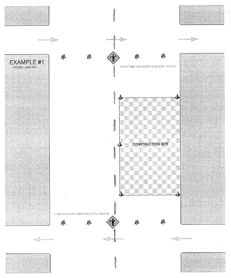
NYC DOT Highway Specifications 422
5/16/2022
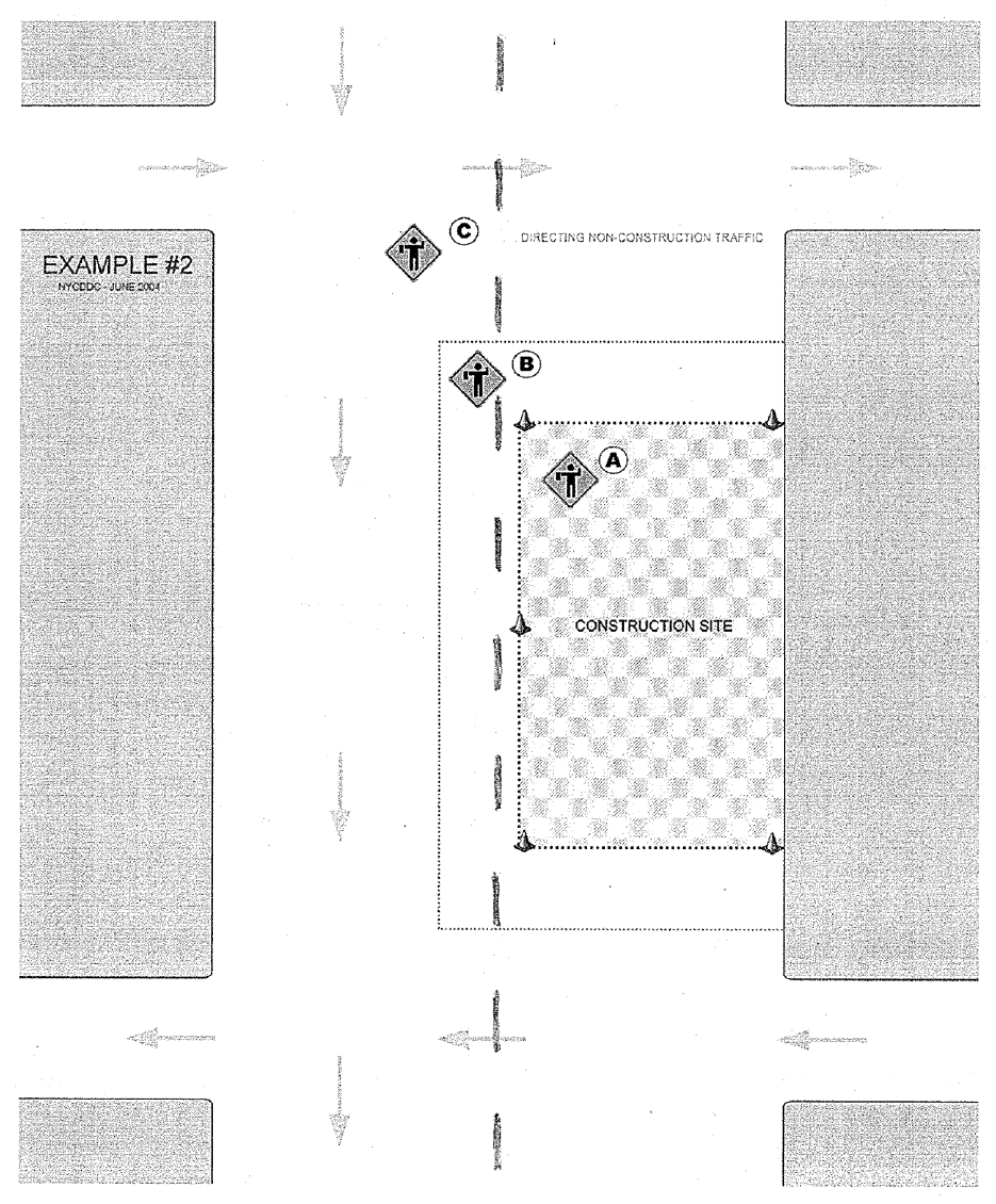
NYC DOT Highway Specifications 423
5/16/2022

NYC DOT Highway Specifications 424
5/16/2022
SECTION 6.53 – Remove Existing Lane Markings
6.53.1. INTENT. This section describes the removal of existing lane markings.
6.53.2. DESCRIPTION. The work shall include the obliterating of designated lane markings on
streets, where shown on the Contract Drawings and as directed by the Engineer.
6.53.3. METHODS. The Contractor shall remove, as soon as practicable, existing pavement
markings where indicated on the Contract Drawings or where ordered by the Engineer. This shall include
any pavement markings that are added during the course of the work. If darkness or inclement weather
interferes with removal operations, such operations should be accomplished during the next daylight period
or as soon thereafter as weather conditions permit.
The method of removal is subject to the approval of the Engineer. Painting out pavement markings will
only be approved for very short term use. Grinding, scraping, sandblasting, etc., must be conducted in
such a manner that the finished pavement surface is not damaged or left in a pattern that will mislead or
misdirect the motorist.
6.53.4. MEASUREMENT. The quantity to be measured for payment shall be the actual number
of linear feet of existing 4” wide lane markings actually removed. Payment for removed markings wider than
4” will be made at the contract price per linear foot of the 4” wide markings removed multiplied by the factor:
Actual Width of Marking Removed (Inches)
4
6.53.5. PRICE TO COVER. The contract price bid per linear foot shall cover the cost of all labor,
plant, materials, equipment, insurance, and incidentals necessary to obliterate designated lane markings,
as shown on the Contract Drawings and as directed, and do all incidental work, all in accordance with the
Contract Drawings, the specifications and the directions of the Engineer.
Payment will be made under:
Item No. Item Pay Unit
6.53 REMOVE EXISTING LANE MARKINGS (4” WIDE) L.F.

NYC DOT Highway Specifications 425
5/16/2022
SECTION 6.54 (NO TEXT)
SECTION 6.55 – Sawcutting Existing Pavement
6.55.1. INTENT. This section describes the full depth sawcutting of the existing pavement at the
locations shown on the Contract Drawings, and as and where directed by the Engineer.
6.55.2. METHODS. Where directed, or shown on the Contract Drawings, the Contractor shall
sawcut through the full depth of the existing pavement with a straight sawcut edge, and do all work as
shown on the detail drawing. All work must be done in a workmanlike manner, to the satisfaction of the
Engineer.
6.55.3. MEASUREMENT. The quantity to be measured for payment shall be the number of linear
feet of existing pavement actually full depth sawcut.
No measurement for payment will be made for any partial depth sawcutting of bituminous pavement, the
cost of which shall be deemed included in the price bid for this item.
The following table summarizes which pavement sawcuts are payable under Item 6.55, and which sawcuts
are included in the costs of other items. Please note that the table is a guide, and the specifications
referenced in the table below govern.
Description
Pay
under
Item
6.55
No
Separate
Payment
Specifications
WATER MAIN TRENCHES:
Full-depth saw cutting of pavements along the initial
opening limits of all water main trenches and
excavations.
☐
☒
NYCDEP
71.11.3.A
Full-depth saw cutting of pavements along the edges of
all trenches and excavations for cutbacks of trenches and
excavations required for water mains 24-Inches and
larger in diameter and appurtenant structures.
☐
☒
NYCDEP
71.11.3.A
Full-depth saw cutting of pavements along the edges of
all trenches and excavations for cutbacks of trenches and
excavations required in streets protected by New York
City Administrative Code §19-144 (Local Law No. 14) for
water mains 20-inches and less in diameter.
☒
☐
NYCDEP
71.11.3.A
Full-depth saw cutting of asphaltic top course along the
edges of all water main trenches and excavations for
cutbacks of asphaltic top course.
☐
☒
NYCDEP
71.11.3.A
Full-depth saw cutting of pavements across the widths of
all water main trenches, excavations and cutbacks.
☐
☒
NYCDEP
71.11.3.A
SEWER TRENCHES:
Full-depth saw cutting of pavements along the initial
opening limits of all sewer trenches and excavations
☐
☒
NYCDEP
71.11.3.B
Full-depth saw cutting of pavements along the edges of
all trenches and excavations for cutbacks of trenches and
excavations required for sewer conduits and appurtenant
structures.
☐
☒
NYCDEP
71.11.3.B

NYC DOT Highway Specifications 426
5/16/2022
Description
Pay
under
Item
6.55
No
Separate
Payment
Specifications
Full-depth saw cutting of asphaltic top course along the
edges of all sewer trenches and excavations for cutbacks
of asphaltic top course.
☐
☒
NYCDEP
71.11.3.B
Full-depth saw cutting of pavements across the widths of
all sewer trenches, excavations and cutbacks.
☐
☒
NYCDEP
71.11.3.B
CATCH BASINS:
Saw cutting of existing sidewalk and curb 1’ from the
perimeter of the catch basin where sidewalk and curb
restoration is not called for under the contract.
☐
☒
NYCDEP
51.41.3.B.3
MICROTRENCHING:
Saw cutting of sidewalks and/or streets for
microtrenching.
☐
☒
NYCDOT
8.00MT.2
OTHER TRENCHES AND PAVEMENT RESTORATION AREAS:
Full-depth saw cutting of all sidewalks and curbs along the
limits of all sewer and water main trenches and
excavations.
☐
☒
NYCDEP
71.11.3.C
Full-depth saw cutting and/or partial-depth saw cutting of
all pavement keys, and pavement adjustment and
transition sections.
☐
☒
NYCDEP
71.11.3.C
Partial-depth precutting or scoring of existing pavement.
☐
☒
NYCDEP
71.11.6
PAVEMENTS, SIDEWALKS, AND CURBS:
Saw cutting construction joints for concrete pavement.
☐
☒
NYCDOT
4.05.5
Saw cutting construction joints for integral concrete curb
and gutter.
☐
☒
NYCDOT
4.08.9
Saw cutting existing sidewalk for new sidewalk
installation.
☐
☒
NYCDOT
4.13.4.(A)
Saw cutting sidewalks to remain for replacement of curbs
(cut existing sidewalk 2’ parallel from the curb).
☐
☒
NYCDOT
1.06.48 (T)
Full depth saw cutting of existing pavement to be
removed by lifting from the adjacent pavement as part of
special care work methods near transit facilities
☐
☒
NYCDOT
6.02 XSCW.5
Saw cutting the existing joint lines prior to removal of
existing bluestone flags.
☐
☒
NYCDOT
6.07.6
Saw cutting the existing asphaltic wearing course
pavement 1-1/2" deep prior to milling.
☐
☒
NYCDOT
6.75.2.(D)
Saw cutting of curb and sidewalk to be removed by hand
demolition as part of special care excavation.
☐
☒
NYCDOT
8.02.3

NYC DOT Highway Specifications 427
5/16/2022
Description
Pay
under
Item
6.55
No
Separate
Payment
Specifications
NEW SIDEWALK TREE PITS:
Saw cutting existing sidewalk to install new tree pits.
☐
☒
NYCDOT
4.16.5.D.9
The planting of trees requires saw cutting and removal of
existing sidewalks, the cost of such work shall be
deemed included in the prices bid for the respective Tree
Planting items of the contract.
☐
☒
NYCDEP
10.06.C
TEST PITS:
Saw cutting for test pits.
☐
☒
NYCDOT
7.16.2
Saw cutting for exploratory test pits for vaults.
☐
☒
NYCDOT
9.00.4
SAWCUTS SHOWN TO BE PAID OR AS DIRECTED:
Full depth sawcuts shown to be paid under Item 6.55 or
as directed by the Engineer.
☒
☐
NYCDOT
6.55
6.55.4. PRICE TO COVER. The contract price per linear foot shall cover the cost of all labor,
materials, plant, equipment, insurance, and incidentals necessary to cut existing pavement with sawcuts,
do all necessary chiseling, tack coating of edges, etc., and do all other necessary incidental work, all in
accordance with the Contract Drawings, the specifications and the directions of the Engineer.
Sawcutting of sidewalk, to allow for curb reconstruction, shall be deemed included in the contract prices bid
for curb construction.
Sawcutting of pavement for test pits in pavements designated to be removed under other contract items
and to install sewer and water main pipe and/or their facilities shall be deemed included in the contract
prices bid for those items, unless otherwise specified.
Payment will be made under:
Item No. Item Pay Unit
6.55 SAWCUTTING EXISTING PAVEMENT L.F.
NYC DOT Highway Specifications 428
5/16/2022
SECTIONS 6.56 AND 6.57 (NO TEXT)
SECTION 6.58 – Tack Coat
6.58.1. WORK TO INCLUDE. Under this section, the Contractor shall apply an approved tack
coat to areas designated by the Engineer.
6.58.2. MATERIALS. Liquid Asphalt (RC-70), Emulsified Asphalt (RS-1), or Asphalt Cement (AC-
20) complying with the requirements of Sections 2.03, 2.04, and 2.05 respectively, shall be furnished and
applied.
6.58.3. EQUIPMENT. The Contractor shall provide a distributor for applying tack coat.
The distributor shall be self-propelled of an approved type designed, equipped, maintained and operated
so that the tack coat can be heated and applied uniformly on variable widths of surface up to 15 feet at
readily determined and controlled rates from 0.03 to 2.0 gallons per square yard, with uniform pressure,
and with an allowable variation from any specified rate not to exceed 0.02 gallons per square yard.
Distributor equipment shall include a tachometer capable of registering the rate of travel in feet per minute,
an accurate continuous metering device certified by an approved testing laboratory, and a certified
thermometer for measuring the temperature of tank contents. Distributors shall be equipped with a power
unit for the pump, and full circulation spray bars adjustable laterally and vertically.
The distributor may be equipped with an attached bristle broom designed such that it drags on the pavement
behind the spray bars. If the broom is used, it shall be adjustable laterally and vertically so that the full
width of the applied tack coat is broomed uniformly into the pavement surface.
Distributor shall be equipped with an approved bituminous material sampling valve capable of producing
representative samples of all material in the tank.
Hand held power spray units or manual hand spray equipment will not be permitted except where
specifically approved by the Engineer and only in areas where the Engineer determines that the use of a
self-propelled distributor is impractical. Where hand operated units are approved it shall be understood
that an approved material metering procedure shall be provided.
6.58.4. METHODS.
(A) SURFACE PREPARATION
Surfaces to be tack coated shall be thoroughly swept and cleaned, as often as required, to remove all dirt,
loose and foreign matter, and be free of standing water. Street sweeping equipment shall be a power
operated sweeper/broom in combination with a vacuum debris lifter and shall be of a type approved by the
Engineer. No tack coat shall be applied unless the surface on which it is to be applied is in a condition
acceptable to the Engineer.
All structures such as manhole, basin, valve box, and electrical box frames and covers, joints, and steel
faced curbs within areas to be tack coated shall be masked with tar paper, polyethylene film or other
approved material. A splash board may be substituted to protect the curb face from being stained with tack
coat spray.
(B) TACK COAT APPLICATION
Tack coat shall be uniformly applied by a pressure distributor to a prepared clean pavement. The tack coat
shall be applied as approved by the Engineer to offer the least inconvenience to traffic and to prevent pickup
or tracking of the bituminous material.
No tack coat shall be applied on a wet or frozen pavement surface. RS-1 shall not be applied when the
surface temperature is below 45 degrees F. RC-70 and AC-20 shall not be applied when the surface
temperature is below 35 degrees F.
Tack coat material should be heated to the proper temperature so that it is fluid enough to be sprayed from
the distributor nozzles. The Contractor shall furnish to the Engineer a temperature-viscosity chart for the
material to be used.
NYC DOT Highway Specifications 429
5/16/2022
Tack Coat
Material Spray Temp. Application Rate
(Deg. F.) (Gal./Sq. Yd.)
Liquid Asphalt
(RC-70) 120-190 0.0– - 0.08
Emulsified Asphalt
(RS-1) 70-140 0.0– - 0.06
Asphalt Cement
(AC-20) 275-400 0.0– - 0.06
Within the above specified tack coat application rate, the actual amount used will be dependent upon the
existing surface texture. An open texture or milled surface will require more tack coat than a tight surface
or one that is “fat” or flush because of the increased surface area. In general, the correct amount of tack
coat sprayed on the surface will leave some of the existing surface still visible through the tack coat.
The application rate shall be 0.03 to 0.07 gallons/yard
2
as approved by the Engineer. Table 6.58-I contains
recommended application rates for tack coat on various surfaces:
TABLE 6.58-I
TACK COAT APPLICATION RATES
Surface Type
Application Rate
(gallons/yard
2
)
New Hot Mix Asphalt
0.03 - 0.04
Milled Surfaces
0.05 - 0.06
Existing Hot Mix Asphalt
0.05 - 0.06
Portland Cement Concrete
0.04 - 0.07
Vertical Surfaces (curbs, concrete
drainage structures and appurtenances)
0.06 - 0.07
Application rate of tack coat shall be constantly controlled by the Contractor and monitored by the Engineer
in job segments using the tachometer and distributor metering gauges, not by the total quantity of tack coat
used averaged over the entire project area applied.
Tack coat shall be uniformly distributed, without atomization, over the areas designated by the Engineer by
means of a pressure distributor and in such manner as not to defile or discolor adjacent curbs or other
structure surfaces. Approximately 50 gallons of tack coat should be left in the distributor to prevent air from
entering the applicator, causing insufficient application in the end area of the spread.
Contractor shall be required to keep on hand an adequate supply of sand or other approved absorbent
material at the job site when applying tack coat. Where the application rate of tack coat exceeds that
required by more than 0.02 gallons per square yard, as determined by the Engineer, the Contractor shall
be required to immediately soak up the excess material with an application of sand or other absorbent
material before the tack coat cures. The absorbed tack coat shall then be removed and disposed in an
appropriate manner away from the site. No additional payment will be made for this work, including but not
limited to removal of sand, additional sweeping, and cleaning.
Prior to paving, the tack coat shall be allowed to cure to a condition where it is tacky to the touch. No
greater area shall be treated in any one day than is planned to be covered by asphaltic concrete during the
same day, unless otherwise authorized in writing by the Engineer.
All vehicular traffic must be kept off the tack coat at all times. Under unusual circumstances, if traffic must
travel over the tack coat before the overlay is placed, a light layer of sand shall be spread on top of the
Liquid Asphalt (RC-70) or Emulsified Asphalt (RS-1) tack coats, to prevent the pickup of tack coat material
by traffic. Excess sand should be broomed from the pavement surface before the overlay is placed to
assure proper bond between the overlay and the existing surface.
All pedestrian traffic shall be blocked from entering areas of newly applied tack coat using suitable traffic
control devices and procedures under the appropriately scheduled contract items.
Failure to comply with the above requirements shall result in a shutdown of both the tack coat and paving
operations until remedial actions are taken by the Contractor to bring the tack coat application within the
NYC DOT Highway Specifications 430
5/16/2022
permitted tolerance. In addition, any asphaltic concrete wearing course material placed on improperly
applied tack coat shall be removed and replaced by the Contractor at no additional cost to the City.
6.58.5. MEASUREMENT. The quantity to be measured for payment shall be the number of square
yards of surface actually tack coated.
6.58.6. PRICE TO COVER. The contract price per square yard shall cover the cost of all labor,
materials, plant, equipment, insurance, and incidentals necessary to prepare the surfaces, spray tack coat,
and do all other incidental work, all in accordance with the Contract Drawings, the specifications, and the
directions of the Engineer.
When there is no scheduled item provided therefore, the cost of furnishing and placing Tack Coating shall
be deemed included in the prices bid for the various asphaltic concrete wearing course and/or macadam
pavement items, as appropriate.
Payment will be made under:
Item No. Item Pay Unit
6.58 TACK COAT S.Y.

NYC DOT Highway Specifications 431
5/16/2022
SECTION 6.59 – Concrete Barrier
6.59.1. INTENT. This section describes the construction of concrete barriers.
6.59.2. DESCRIPTION. The Contractor shall construct concrete barriers of the types and
conforming to the various details shown on the New York State Department of Transportation Standard
Sheet for Concrete Barrier.
6.59.3. MATERIALS.
(A) Concrete shall be Class B-32, Type IA, conforming to the requirements of Section 3.05.
An approved air-entraining agent shall be added at the time concrete ingredients are mixed with water, to
achieve an air content of 7% (5% Min., 9% Max.). Cement shall be White Portland Type I; light colored
sand-Type IA; light colored coarse aggregate Type I, Grade B, or Type 2, Size No. 57. Slump shall be 4
inches + 1 inch.
(B) Joint filler shall comply with the requirements of Section 2.15, Type IV, Bituminous Fiber.
(C) Joint sealer shall comply with the requirements of Federal Specification TT-S-230, Sealing
Compound, Synthetic-Rubber Base, Single Component, Chemically Curing. The color of the compound
shall be white.
6.59.4. METHODS.
(A) The Contractor shall pour each type of concrete barrier in monolithic form, in lengths not
exceeding 60 linear feet. Transverse joints shall extend through the entire section. Joints shall be filled
with premolded joint filler, placed flush with a recess of 1/2” from the face and top of the barrier, and caulked
with joint sealer.
When the ambient temperature falls below 40 degrees F., no pouring of concrete will be permitted.
(B) All forms, including forms for curved sections, shall be made of metal and of such
construction that there will be minimum interference to inspection for grade and alignment. Forms shall be
braced and secured adequately so that no discernible displacement from alignment or grade will occur
during placement of concrete. Where radii are less than 40 feet, forms shall be curved to the design radius.
(C) Concrete Placing and Vibrating: Concrete shall be compacted by means of approved
immersion type mechanical vibrators. The vibrator shall be inserted into the concrete at one foot intervals.
The vibrator shall be of a size and weight sufficient to thoroughly vibrate the entire concrete mass without
damaging or misaligning the forms and reinforcement.
(D) Removal of Forms and Finishing Surfaces: Forms shall be left in place for 24 hours or until,
in the judgment of the Engineer, the concrete has sufficiently set so the forms may be removed without
injury to the barrier. Immediately after the forms have been removed, surfaces exposed to view shall have
all projections and irregularities carefully removed and all cavities neatly filled with mortar of the proportion
used in the concrete. The same brand of cement and the same kind of aggregate shall be used for filling
cavities as was used in the original concrete mix. Plastering of repaired surfaces will not be allowed. The
surface film of all such repaired surfaces shall be carefully removed before setting occurs.
The finished surface of the barrier shall be smooth, dense, unpitted and free from air bubble pockets,
depressions and honey combs. If the Engineer deems it necessary, the barrier shall be given a wood float
finish in order to obtain the above mentioned finish.
(E) Concrete Curing: Curing of concrete barrier shall conform to the requirements specified
therefor under Subsection 4.06.10.
(F) Where the Contractor chooses to precast the concrete barrier, it shall be constructed in
accordance with the following requirements:
Precast Concrete Barrier:
1. Fabrication: Precast concrete barrier shall be fabricated to conform to the shapes and sizes shown
on the Contract Drawings. The length of precast concrete barrier shall be 30 foot maximum. All
surfaces exposed after installation shall be cast in steel forms.

NYC DOT Highway Specifications 432
5/16/2022
The Contractor shall provide the Engineer with shop drawings and detailed construction procedures
of the barrier. The shop drawings shall show the form dimensions and location and type of
reinforcement in the precast concrete barrier. The drawings shall be delivered to the Engineer for
approval ten (10) working days before fabrication is to begin. No work shall begin until the drawings
are approved.
The tolerance on placement of reinforcing steel in the barrier shall be + 1 inch. The chairs, spacers
or other devices used to maintain the reinforcement in position shall have rust resistant tips so that
no spots will show on the finished faces. The cost of any steel reinforcement required to transport
the precast barrier shall be included in the cost of these items.
Concrete shall be consolidated in the forms by internal vibrators. Exposed surfaces shall be free
from objectionable imperfections, such as honeycomb and air voids as determined by the Engineer.
If air voids collect at the interface of the concrete and forms, the forms shall be tapped on the
outside with rubber mallets or similar devices to displace the entrapped air.
2. Curing: The precast barrier sections may be cured by means of quilted covers which shall be kept
wet, or by using polyethylene coated burlap blankets which will not require wetting. Polyethylene
coated blankets shall be laid dry with the burlap side against the concrete, and adjoining blankets
shall be lapped sufficiently to provide a moisture seal. Retention of moisture for curing by any of
the above methods shall be continued for a minimum of 7 days.
If the precast concrete barrier sections are steam cured, the sections shall be cured in an enclosure
free from outside drafts, and cured in a moist atmosphere. The temperature shall be maintained
at a temperature between 125 degrees and 160 degrees F. by the injection of steam for a period
of not less than 12 hours. Steam curing shall not begin in less than 2 hours from the time that the
last concrete was placed. Care shall be taken by the Contractor to prevent localized “hot spots”
caused by the steam lines. A continuous temperature time recorder is required for each enclosure.
The temperature of the curing atmosphere for any method shall not be increased or decreased at
a greater rate than 40 degrees F. per hour.
3. Repair: Where approved by the Engineer, occasional imperfections in manufacture or those
caused by mishandling may be repaired. The repairs shall be properly finished and cured. The
color of the repaired area shall match as closely as possible with the rest of the barrier color. The
repairs may be made with a mixture of sand and Portland cement. The repairs shall be made to
the satisfaction of the Engineer.
4. Sampling and Testing: The concrete in the precast concrete barrier shall be sampled and tested
by an approved testing laboratory. Costs for testing and sampling shall be paid by the Contractor.
5. Basis of Acceptance: The precast barrier sections shall be accepted at the job site.
6.59.5. MEASUREMENT. The quantity to be measured for payment shall be the number of linear
feet of each type of concrete barrier actually constructed, including transition sections, measured along the
centerline of the top surface of each barrier.
6.59.6. PRICES TO COVER. The contract price bid per linear foot for each type of concrete barrier
shall cover the cost of all labor, materials, equipment, insurance, and incidentals necessary to complete the
work, including forms, joint materials of any type, finishing, curing, and any other work or materials required
to satisfactorily complete the work, all in accordance with the Contract Drawings, the specifications and the
directions of the Engineer.
Payment will be made under:
Item No. Item Pay Unit
6.59 A CONCRETE BARRIER, TYPE A L.F.
6.59 B CONCRETE BARRIER, TYPE B L.F.
6.59 C CONCRETE BARRIER, HALF SECTION L.F.
NYC DOT Highway Specifications 433
5/16/2022
SECTION 6.59 P – Temporary Concrete Barrier
6.59P.1. INTENT. This section describes the work to be done in connection with temporary concrete
barriers.
6.59P.2. DESCRIPTION. The Contractor shall furnish, install, move, maintain and remove lighted
temporary concrete barriers. Except as otherwise shown on the Contract Drawings, specified or directed
by the Engineer, the material, manufacture, fabrication and installation or erection of temporary concrete
barrier shall be in compliance with current New York State Department of Transportation (NYSDOT)
Standard Sheets for Temporary Concrete Barrier.
6.59P.3. MATERIALS. Temporary concrete barriers shall conform to the dimensions, joint
connection, material details, and anchoring details shown on the NYSDOT’S Standard Sheet 619-01,
except as otherwise shown on the Contract Drawings. The barrier sections shall be precast portable
concrete units. The Manufacturer shall certify that the temporary concrete barrier units conform to the
details shown on the aforementioned NYSDOT’S Standard Sheet or approved drawing.
The Engineer will inspect the temporary concrete barrier sections upon delivery to the project site for
conformance to specifications. Any barrier sections having damage and/or defects in the concrete and/or
joint connections will be rejected by the Engineer when in the Engineer’s judgment the performance of the
barriers will be affected.
The temporary concrete barrier sections shall form a smooth and continuous barrier when joined together.
Any sections damaged or misaligned while in service shall be corrected or replaced to the satisfaction of
the Engineer.
Unless otherwise directed, all barricades shall be striped on the roadway side of the barricade with reflective
sheet material in accordance with the Contract Drawings, the National Manual on Uniform Traffic Control
Devices for Streets and Highways (National MUTCD), 2009 or latest Edition, or as directed by the Engineer.
The reflective sheet material shall conform to photometric and color (Orange and White) requirements of
Subsection 730-05.02, Reflective Sheeting (Class B), of the State of New York, Department of
Transportation, Standard Specifications.
Where indicated on the Contract Drawings, concrete barricades shall be supplemented by approved low
intensity steady burning yellow lights in accordance with the requirements of Subsection 619.3.03 of the
NYSDOT Standard Specifications.
For temporary concrete barrier with fence, the barrier shall be modified to accommodate a chain link fence
with posts. Top and bottom rails will not be required for the fence. The Contractor shall be required to
provide a solid, secure chain link fence system consisting of posts, post embedment, fence fabric, and all
other incidentals as may be required. Fence posts shall be embedded in the concrete barrier and the chain
link fence shall extend from the barrier to a height of at least six (6) feet above grade. Maximum spacing of
fence posts shall be eight (8) feet from center to center. Minimum embedment of fence posts into the
barrier shall be four (4) inches deep. Fence fabrication shall be continuous for the length of the concrete
barrier; however, at joints between concrete barriers, the gap between fence sections shall not be more
than four (4) inches.
6.59P.4. METHODS. The Contractor shall furnish, erect, move, and remove temporary concrete
barriers where and as indicated on the Contract Drawings or as directed by the Engineer.
Where indicated on the Contract Drawings or in the proposal, temporary concrete barriers shall be
supplemented by approved steady burning lights.
Each run, or bay, of temporary concrete barrier unit shall be fastened together to form a continuous chain.
After placement, each successive unit shall be moved longitudinally to remove the slack in the joint between
units. The units at each end of a run or bay shall be anchored as shown on the Standard Sheet. Where
shown on the Contract Drawings or directed by the Engineer, the ends of the barrier run shall be fitted with
a tapered end section, flared back.
6.59P.5. MEASUREMENT. The quantity to be measured for payment shall be the number of linear
feet of temporary concrete barrier actually placed including transition sections, measured along the
centerline of the top surface of each barrier.
NYC DOT Highway Specifications 434
5/16/2022
Payment will be made for temporary concrete barrier only for the initial installation at any location.
Whenever temporary concrete barriers are moved to a new location, as required by the Contract Drawings
or directed by the Engineer, payment will be made in the same manner as if it were an initial installation.
Whenever the Contractor proposes to move curb to a new location, it is subject to approval of the Engineer
and must be in accordance with the latest approved progress schedule. Minor movement of the temporary
concrete barrier within a work area will not be considered as a movement to a new location and will not
entitle the Contractor to additional payment. Minor movement within a work area includes, but is not limited
to:
• Movement from one side of the roadway to the other side
• Movement to adjust the roadway or work zone width
• Movement required to access the work zone or to secure the work zone
• Linear movement of less than one block within an established work zone
• Rearrangement within a work area
6.59P.6. PRICE TO COVER. The contract price bid per linear foot for each type of concrete barrier
shall cover the cost of all labor, materials, equipment, insurance, and incidentals necessary to erect,
maintain, and remove the required barrier, including any required connection devices, orange and white
reflective stripes on the faces of the barriers, steady burning yellow lights, delineation or guiding devices,
all in accordance with the Contract Drawings, the specifications and the directions of the Engineer.
Payment will be made under:
Item No. Item Pay Unit
6.59 P TEMPORARY CONCRETE BARRIER L.F.
6.59 PF TEMPORARY CONCRETE BARRIER WITH FENCE L.F.
6.59 PH TEMPORARY CONCRETE BARRIER, HALF SECTIONS L.F.
NYC DOT Highway Specifications 435
5/16/2022
SECTION 6.60 – Asphalt Block Pavers
6.60.1. WORK TO INCLUDE. Under this section, the Contractor shall furnish and install new
asphalt block pavers and relay existing asphalt block pavers. Pavers shall be installed on a three-quarter
(3/4”) inch thick bituminous setting bed, laid on a three (3”) inch foundation course of screenings, unless
otherwise shown on the Contract Drawings.
6.60.2. MATERIALS.
(A) NEW ASPHALT BLOCK PAVERS
New Asphalt Blocks shall be hexagonal and/or rectangular, of the type(s) shown on the Contract Drawings
and in compliance with the requirements of Section 3.04, unless otherwise specified herein or indicated on
the Contract Drawings.
Color, size, texture, and surface appearance of new asphalt block pavers shall match that of the existing
adjacent pavers, unless otherwise specified on the Contract Drawings.
(B) WATER BOUND STONE SCREENINGS BASE
Stone screening shall be either limestone or traprock and shall consist of hard, durable, sharp angled
fragments, free from dirt or other deleterious, matter, graded within the following limits:
100% passing 1/2” square opening screen
20% to 40% passing 20 mesh sieve
5% to 15% passing 200 mesh sieve
Material substitutions will not be approved under any circumstances. All recycled materials will be rejected.
(C) BITUMINOUS SETTING BED
Asphalt cement to be used in the bituminous setting bed shall conform to ASTM Designation D 946 with a
Penetration Grade of 85 - 100.
The fine aggregate to be used in the bituminous setting bed shall be clean, hard sand with durable particles
and free from adherent coatings, lumps of clay, alkali salts, and organic matter. It shall be uniformly graded
from “coarse” to “fine” and all passing the No. 4 sieve and meet the gradation requirements when tested in
accordance with the standard method of test for sieve or screen analysis of fine and coarse aggregates
ASTM Designation C136.
The dried fine aggregate shall be combined with hot asphalt cement, and the mix shall be heated to
approximately 300 degrees Fahrenheit at an asphalt plant. The approximate proportion of materials shall
be seven and one-half (7-1/2%) percent cement asphalt, eighty-seven and one-quarter (87-1/4%) percent
sand, and five and one-quarter (5-1/4%) percent mineral filler. Each ton shall be apportioned by weight in
the approximate ratio of 150 lbs. asphalt to 1,745 lbs. sand and 105 lbs. mineral filler. The Contractor shall
determine the exact proportions to produce the best possible mixture for construction of the bituminous
setting bed to meet construction requirements.
(D) NEOPRENE-MODIFIED ASPHALT ADHESIVE
Neoprene-Modified Asphalt Adhesive shall consist of two (2) percent neoprene (Grade WM 1) oxidized
asphalt with a 155 degree softening point (80 penetration).
(E) JOINT FILLER
Joint Filler shall be clean, hard sand with durable particles free from adherent coatings, lumps of clay, alkali
salts, and organic matter.
6.60.3. METHODS. Prior to Commencement of Work, the Contractor shall submit the name of the
block manufacturer(s) and installer proposed to use and upon which the Contractor’s bid is based, along
with their respective work history experience, and at least one sample of each different block which will be
used in the project. The manufacturer and installer shall have a minimum of five (5) years of documented
experience in block paver work.
NYC DOT Highway Specifications 436
5/16/2022
UNDER NO CIRCUMSTANCE SHALL ANY EXISTING ASPHALT PAVERS BE EXCAVATED OR
REMOVED WITHOUT WRITTEN PERMISSION AND DIRECTION BY THE ENGINEER AS TO WHICH
PAVERS ARE TO BE RESET IN THE NEW WORK.
Existing pavers designated to be removed and reset shall be carefully removed, cleaned of all adherent
material, and stored for resetting by the Contractor.
(A) PREPARATION OF SURFACE
The Contractor shall trim subgrade to smooth uniform lines to the satisfaction of the Engineer. The
subgrade shall be compacted with equipment that will yield the following density:
Cohesive Subgrade – Minimum of 95% of AASHTO T180 Method density.
Cohesionless Subgrade – Minimum of 100% of AASHTO T180 Method D density.
The Contractor shall remove from the subgrade all debris, foreign and other undesirable material which
interferes with satisfactory construction. The fine grade shall not be muddy or otherwise unsatisfactory
when the base course material is placed upon it. If the fine grade becomes rutted or displaced, due to any
cause whatsoever, the Contractor shall regrade same without additional payment. The Contractor shall
trim subgrade to smooth uniform lines to the satisfaction of the Engineer.
(B) SPREADING OF STONE SCREENING BASE
The spreading of stone screenings shall be done from suitable spreading equipment or from piles dumped
along the edge of the proposed pavement. Screening shall be evenly spread so that the foundation course
will have, after rolling, the required thickness of three (3”) inches, unless otherwise shown on the Contract
Drawings. No segregation of large or fine materials will be allowed, but the screening as spread shall be
well graded with no pockets of fine material.
(C) ROLLING OF STONE SCREENINGS
After the screenings have been properly spread, they shall be thoroughly compacted by rolling with an
approved roller weighing not less than ten (10) tons except in tree pit area. The stone screenings shall be
sprinkled and saturated immediately before being rolled, the sprinkler being followed by the roller. If the
material becomes wet to such an extent that the pavement becomes unstable and waves under the roller,
the roller shall be taken off and this portion left to dry out before it is resumed.
More screenings shall be added where necessary, and the sprinkling and rolling shall continue until the
foundation has been properly compacted. If necessary to secure satisfactory results in the opinion of the
Engineer, the foundation shall be sprinkled and backrolled on succeeding days. The Contractor shall
maintain and repair the foundation courses until the blocks have been placed.
(D) PLACING BITUMINOUS SETTING BED
The bituminous setting bed cushion shall be placed to proper elevation and grade by the use of depth
control bars (3/4” thickness) placed directly over the stone screenings. If grades must be adjusted, set
wood chocks under depth control bars to proper grade. Set two bars parallel to each other approximately
eleven (11’) feet apart to serve as guides for striking board (12’ long 2” x 6” board). The depth control bars
must be set carefully to bring the pavers, where laid, to proper grade.
Place some bituminous bed between the parallel depth control bars. Pull this bed with the striking board
over these bars several times. After each passage, low porous spots must be showered with fresh
bituminous material to produce a smooth, firm and even setting bed. As soon as this initial panel is
completed, advance the first bar to the next position in readiness for striking the next panel. Carefully fill
up any depressions that remain after removing the depth control bars and wood chocks.
The bed shall be spread in a continuous workmanlike manner. Installation of bed in spotted, different and
isolated areas will not be accepted. Bed depth greater than one and one-eighth (1-1/8”) inch will not be
acceptable. The Contractor shall remove and replace stone screening base required to maintain specified
bed thickness. Minimum replacement thickness of stone screening base shall be two (2”) inches.
After the bed has cooled, it shall be rolled by hand with a one hundred (100 lb.) pound roller to eliminate
sponginess and to prepare the surface for the installation of the tack coat. The setting bed shall be
protected against all pedestrian traffic and construction equipment to insure a level surface for setting
pavers.
NYC DOT Highway Specifications 437
5/16/2022
In tree pit areas after trees have been planted and topsoil placed, a layer of stone screenings shall be
placed and tamped.
The Sand Cushion around tree pits shall consist of clean, hard durable uncoated stone particles free from
lumps of clay and all deleterious substances and shall be so graded when dry, one hundred per cent shall
pass a one-quarter (1/4”) inch square opening sieve: not more than thirty-five (35) percent by weight shall
pass a No. 50 sieve. Sand Cushion may be rejected if it contains more than ten per cent by weight of loam
and silt.
(E) NEOPRENE-MODIFIED ASPHALT ADHESIVE
The neoprene-modified asphalt adhesive tack coat shall be applied by mopping, squeegeeing or troweling
over the top of the setting bed to a uniform thickness of approximately 1/16” so as to provide a bond between
the bituminous setting bed and the paver. If it is troweled, the trowel shall be serrated with serrations not
to exceed one-sixteenth (1/16) of an inch.
(F) LAYING ASPHALT BLOCK PAVERS
When the modified asphalt adhesive is dry to the touch, carefully place the pavers by hand, ground finish
side up unless otherwise specified, in straight courses, with hand tight joints and uniform top surfaces,
keeping full alignment according to the patters shown on the Contract Drawings. Block shall be laid on the
bed before it has set. The blocks shall be carefully laid with the best face up, in straight courses at right
angles to the line of the street or at such other angles as may be directed. Joints shall be hand tight and
read from zero (0) to one-eighth (1/8”) inch maximum.
All blocks shall be clean when placed in the pavement. Blocks which in the opinion of the Engineer are not
satisfactorily clean shall be washed before placing.
Pavers may vary slightly in shade and tonality. Where four or more pallets of pavers are required to be laid
in the project, the installer shall work from at least four (4) pallets at a time in order to create a uniform blend
of paver shades.
All blocks shall be clean when placed in the pavement. Blocks which in the opinion of the Engineer are not
satisfactorily clean shall be washed before placing. Cutting of blocks shall be clean, straight and smooth
and performed in strict accordance with the manufacturer’s recommendations. All cut block that is chipped,
cracked or otherwise flawed shall be discarded as directed by the Engineer, at no additional cost to the
City.
In no case shall the bituminous setting bed in front of the pavement be disturbed or walked on during the
laying of the blocks.
After a sufficient number of blocks have been laid, all broken or misshapen blocks shall be marked by the
Engineer and removed and replaced by the Contractor at no additional cost to the City.
When all objectionable blocks have been removed from the pavement and all replacements made, the
pavement shall be swept clean and shall be tested with straightedge laid parallel with the center line and
any depression exceeding one-quarter (1/4”) inch shall be corrected and brought to proper grade. All blocks
disturbed in making replacements or correcting depressions shall be settled into place by ramming, and the
filler shall then be applied.
Each section of pavement must be acceptable to the Engineer before the application of filler.
In no case shall the setting bed in front of the pavement be disturbed or walked on during the laying of
blocks.
Cutting of blocks shall be clean, straight, and smooth and performed in strict accordance with the
manufacturer’s recommendations. All cut blocks that are chipped, cracked, or otherwise flawed shall be
discarded and replaced, as directed by the Engineer, at no additional cost to the City.
Existing asphalt block pavers may be rejected by the Engineer for re-use because of excessive roundness
or other objectionable characteristics.
Any shortage in block to be relaid due to the Contractor’s negligence as determined by the Engineer shall
be supplied and incorporated in the work by the Contractor at the Contractor’s own expense.
After a sufficient number of blocks have been laid, all broken or misshapen blocks shall be marked by the
Engineer and removed and replaced by the Contractor.
NYC DOT Highway Specifications 438
5/16/2022
When all objectionable blocks have been removed from the pavement and all replacements made, the
pavement shall be swept clean and shall be tested with an approved straight-edge ten (10’) feet long or
with an approved surface testing machine laid parallel with the center line and any depression exceeding
one-quarter (1/4”) inch shall be corrected and brought to proper grade. All blocks disturbed in making
replacements or correcting depressions shall be settled into place by ramming, and the filler shall then be
applied.
Each section of pavement must be acceptable to the Engineer before the application of filler.
(G) JOINT FILLER
Upon the completion of the work of laying the blocks in each section to the satisfaction of the Engineer, the
surface of the blocks shall be swept clean, and the joints filled with dry sand.
All joints shall be filled the same day as the blocks are laid. In no case shall a wearing course be left
overnight or when work is stopped without the joint filling being completed. Filler shall not be applied if the
blocks are wet or if the air conditions are such that the filler does not readily enter the joints.
Filler shall be well worked into the joints by means of squeegees or other approved devices operating slowly
backward and forward. Squeegeeing shall continue until the joints are full, flush with the top surface..
Immediately after the joints are filled, the pavement shall be swept clean, fog lightly with water and clean
of all stains.
(H) SUFFICIENCY OF APPARATUS
The apparatus for agitating the filler shall be sufficient in numbers and efficiency to permit the filler gang to
closely follow the pavers or rammers, as the case may be.
(I) TRIAL INSTALLATION
The Contractor shall install approximately 400 sq. ft. area of pavers in a location to be determined by the
Engineer for the purpose of establishing a standard of comparison for the remaining work. Said area shall
include a typical corner quadrant with pedestrian ramp areas. The Engineer shall inspect and approve the
trial area for overall appearance and joint spacing before proceeding with the remainder of the work.
(J) TRAFFIC
No traffic of any kind will be allowed on the wearing course until permitted by the Engineer.
Newly laid pavers must be protected at all times by panels of plywood on which the installer stands. These
panels can be advanced as work progresses. However, the plywood protection must be kept in areas
which will be subjected to continued movement of materials and equipment. These precautions must be
taken in order to avoid depressions and protect paver alignment.
(K) DEFECTIVE WEARING COURSE
Such portions of the completed wearing courses as are defective in finish, compression, composition, or
that do not comply with the requirements of these specifications, shall be taken up, removed and replaced
with suitable materials, properly laid in accordance with these specifications at the Contractor’s own
expense.
6.60.4. SUBMITTALS.
Prior to ordering pavers, the Contractor shall submit four (4) samples of each type of paver they propose
to use for approval by the Engineer. The samples shall be clearly labeled with the Contract No.,
manufacturer, and finish. All pavers used in the work shall conform to the approved samples. A three (3)
pound bag of stone screenings shall be submitted to the Engineer for approval, with a sieve analysis and
the name of the supplier attached.
6.60.5. MEASUREMENT.
(A) ASPHALT BLOCK PAVERS RELAID
The quantity to be measured for payment shall be the number of square yards of asphalt block pavers
relaid on the site, measured in place, to the satisfaction of the Engineer.
NYC DOT Highway Specifications 439
5/16/2022
(B) FURNISH AND INSTALL ASPHALT BLOCK PAVERS
The quantity to be measured for payment shall be the number of square yards of new asphalt block pavers
installed on the site, measured in place, to the satisfaction of the Engineer.
6.60.6. PRICES TO COVER.
(A) ASPHALT BLOCK PAVERS RELAID
The contract price bid shall be a unit price per square yard and shall cover the cost of all labor, materials,
plant, equipment, insurance, and necessary incidentals required to remove, clean, store, and relay existing
asphalt block pavers on the site, including but not limited to stone screenings, bituminous setting bed,
neoprene-modified adhesive and sand, in accordance with the Contract Drawings, the specifications, and
the directions of the Engineer.
(B) FURNISH AND INSTALL ASPHALT BLOCK PAVERS
The contract price bid shall be a unit price per square yard and shall cover the cost of all labor, materials,
plant, equipment, insurance, and necessary incidentals required to furnish, deliver and install new asphalt
block pavers in place on the site, including but not limited to stone screenings, bituminous setting bed,
neoprene-modified adhesive, asphalt block pavers and sand, all in accordance with the Contract Drawings,
the specifications, and directions of the Engineer.
Payment will be made under:
Item No. Item Pay Unit
6.60 A ASPHALT BLOCK PAVERS RELAID S.Y.
6.60 B FURNISH AND INSTALL ASPHALT BLOCK PAVERS S.Y.
NYC DOT Highway Specifications 440
5/16/2022
SECTIONS 6.61 THRU 6.65 (NO TEXT)
SECTION 6.66 – Brick Pavers
6.66.1. WORK TO INCLUDE. Under this section the Contractor shall furnish and install brick
pavers in the appropriate design pattern(s), sizes, shades and colors as shown on the Contract Drawings.
6.66.2. MATERIALS.
(A) BRICK PAVERS
Brick pavers shall be of the sizes, colors and patterns as shown on the Contract Drawings and shall comply
with the requirements of ASTM Designation C 902, “Pedestrian and Light Traffic Paving Brick”, Class SX,
Type I Application PX, except that they shall be fired to produce a dense paver with an absorption of less
than 6% (in a 24-hour cold water absorption test), have a Modulus of Rupture of at least 2,000 psi, and a
compressive strength of not less than 8,000 lbs. per square inch. Brick pavers must be capable of
withstanding at least the equivalent of 50 cycles of freeze-thaw conditions, with no visible deterioration,
have a straight wire-cut finish, be dimensionally stable, and all colors shall be as approved by the Design
Engineer. Circular wire cut pavers will not be allowed. The Contractor shall provide certification from an
approved testing laboratory attesting to the brick’s compliance with the aforementioned water absorption,
compressive strength, Modulus of Rupture, and freeze-thaw requirements as defined under ASTM
Designation C 67.
Prior to commencement of Work, the Contractor shall submit the name of the brick manufacturer and
installer proposed to use and upon which the Contractor’s bid is based, along with their respective work
history experience, and at least one sample of each different brick which will be used in the project. The
manufacturer and installer shall have a minimum of five (5) years of documented experience in brick paver
work. Roadway and sidewalk pavers shall be a standard product of a single manufacturer.
Brick pavers shall be produced by any of the manufactures shown on the Contract Drawings or an approved
equivalent.
(B) BITUMINOUS SETTING BED
Asphalt cement to be used in the bituminous setting bed shall conform to ASTM Designation D 946 with a
penetration at 77 degrees F, 100 G., 5 Sec. of minimum 85 millimeters and maximum of 100 millimeters.
The fine aggregate to be used in the bituminous setting bed shall be clean, hard sand with durable particles
and free from adherent coatings lumps of clay, alkali salts, and organic matter. It shall be uniformly graded
from “coarse” to “fine” and all passing the No. 4 sieve and meet the gradation requirements when tested in
accordance with the standard method of test for sieve or screen analysis of fine and coarse aggregates
ASTM Designation C136.
The dried fine aggregate shall be combined with hot asphalt cement, and the mix shall be heated to
approximately 300 degrees F. at an asphalt plant. The approximate proportion of materials shall be seven
and one-half (7-1/2%) percent cement asphalt, eighty-seven and one-quarter (87-1/4%) percent sand, and
five and one-quarter (5-1/4%) percent mineral filler. Each ton shall be apportioned by weight in the
approximate ratio of 150 lbs. asphalt to 1,745 lbs. sand and 105 lbs. mineral filler. The Contractor shall
determine the exact proportions to produce the best possible mixture for construction of the bituminous
setting bed to meet construction requirements.
(C) NEOPRENE-MODIFIED ASPHALT ADHESIVE
Neoprene-Modified Asphalt Adhesive shall consist of two (2%) percent neoprene (Grade WM 1) oxidized
asphalt with a 155 degree softening point (80 penetration).
(D) JOINT FILLER
Joint Filler shall meet the applicable requirements of Section 3.06 Type 2, and shall be pigmented with
brick dust to match the color of the brick pavers.
(E) CUT BACK ASPHALT
The Contractor shall use an approved cut back asphalt placed on the concrete base for roadway pavers
prior to setting of bituminous setting bed.

NYC DOT Highway Specifications 441
5/16/2022
6.66.3. METHODS.
(A) PLACING BITUMINOUS SETTING BED
The concrete base, which shall be furnished and installed under another contract item, shall be sufficiently
cured prior to installation of the bituminous setting bed as approved by the Engineer. To install the setting
bed over the surface of the base, place three-quarter (3/4”) inch deep control bars directly over the base.
If grades must be adjusted, set wood chocks under depth control bars to proper grade. Set two bars parallel
to each other approximately eleven (11’) feet apart to serve as guides for striking board (12’ long 2” x 6”
board). The depth control bars must be set carefully to bring the pavers, where laid, to proper grade.
Place some bituminous bed between the parallel depth control bars. Pull this bed with the striking board
over these bars several times. After each passage, low porous spots must be showered with fresh
bituminous material to produce a smooth, firm and even setting bed. As soon as this initial panel is
completed, advance the first bar to the next position in readiness for striking the next panel. Carefully fill
up any depressions that remain after removing the depth control bars and wood chocks.
The bed shall be spread in a continuous workmanlike manner. Installation of bed in spotted, different and
isolated areas will not be accepted. Bed depth greater than one and one-eight (1-1/8”) inch will not be
acceptable. The Contractor shall remove and replace the concrete required to maintain specified bed
thickness. Minimum concrete replacement repair thickness shall be two (2”) inches.
After the bed has cooled, it shall be rolled by hand with a one hundred (100 lb.) pound roller to eliminate
sponginess and to prepare the surface for the installation of the tack coat. The setting bed shall be
protected against all pedestrian traffic and construction equipment to insure a level surface for setting
pavers.
The neoprene-modified asphalt adhesive tack coat shall be applied by mopping, squeegeeing or troweling
over the top of the setting bed to a uniform thickness of approximately 1/16” so as to provide a bond between
the bituminous setting bed and the paver. If it is troweled, the trowel shall be serrated with serrations not
to exceed one-sixteenth (1/16) of an inch.
(B) INSTALLATION OF BRICK PAVERS
All brick pavers shall be laid in the pattern shown on the Contract Drawings or as directed by the Engineer
to provide a uniformly even surface. No brick pavers shall be laid or grouted in freezing weather.
Prior to installation of brick pavers, all steel plates required to be installed adjacent to tree pits as shown on
the plan shall have been installed and painted with a shop coat of epoxy primer, an epoxy intermediate coat
and a polyurethane topcoat in accordance with the requirement specified under Subsection 2.13.4., for
the painting of steel facing for concrete curb.
When the modified asphalt adhesive is dry to the touch, carefully place the pavers, best side up, by hand
in straight courses with hand tight joints and uniform top surface. Good alignment must be kept, and the
pattern(s) shall be that shown on the Contract Drawings. All straight patterns shall be straight and all curved
patterns shall be smooth curved. Pavers shall be set flush with a top surface elevation tolerance of 1/16”
between adjacent pavers but not more than +1/32” at perimeters between pavers and adjacent curb or
sidewalk surfaces. Where bricks are to be cut, only machine full depth diamond saw-cut bricks will be
accepted in the work. Brick pavers in corner quadrant or curvilinear patterns shall be cut on a radial. Brick
pavers for meter posts shall be cored through as directed by the Engineer. Brick shall not be cut to less
than one (1”) inch in the least dimension. Areas with dimensions less than 1” shall be wet grouted.
One half inch weep holes at bituminous base shall be provided through curb joints and/or concrete base as
shown on the Contract Drawings.
Newly laid pavers must be protected at all times by panels of plywood on which the installer stands. These
panels can be advanced as work progresses. However, the plywood protection must be kept in areas
which will be subjected to continued movement of materials and equipment. These precautions must be
taken in order to avoid depressions and protect paver alignment.
(C) JOINT TREATMENT
Hand tight joints shall read from 0” to maximum 1/8”. Sweep a dry mixture of joint filler until joints are
completely filled. Fog lightly with water. Brick pavers shall be cleaned of excess grout and joints finished
prior to the grout setting up. All brick paving shall be kept moist for 4 days after filling the joints with grout.
NYC DOT Highway Specifications 442
5/16/2022
Cement stains that remain after the 4 day curing period shall be cleaned with a 10% solution of muriatic
acid or mortar cleaner, or sweep with moist sand, followed by flushing clean with water. Care shall be taken
to avoid the use of acid in areas where runoff could damage trees or other vegetation.
(D) BRICK DELIVERY & TEST STRIPS
Pavers shall be suitably packaged, delivered and unloaded at the site to minimize breakage and chipping
of bricks. Bricks shall be delivered to site prior to installation of concrete base and adjacent sidewalk.
Sample test width strip shall be laid out prior to pouring of concrete base and adjacent sidewalk to conform
to exact number and unit width of selected pavers. Test strip shall be minimum 3 brick courses from curb
to concrete sidewalk and as directed by the Engineer. Test strip locations shall be as shown on the Contract
Drawings and as directed by the Engineer.
(E) TRIAL INSTALLATION
The Contractor shall construct approximately 400 sq. ft. area of brick pavers in a location to be determined
by the Engineer, for the purpose of establishing a standard of comparison for the remaining work. Said
area shall include a typical corner quadrant with pedestrian ramp areas. The Engineer shall inspect and
approve the trial area for color, overall appearance and joint spacing before proceeding with the remainder
of the work.
6.66.4. SAMPLES. A sample of the brick paver(s) of the color, range and dimensions shown on
the Contract Drawings shall be furnished to the Engineer for the Engineer’s written approval prior to delivery
and installation, and after approval shall be used as a Standard for all pavers incorporated into the work.
Samples shall be approved for surface texture, color variations, dimensional stability, color contrast (where
more than one brick or pattern is indicated) and shall generally be equal to sample(s) on display for the
project, and written approval will be required prior to installation.
6.66.5. TRAFFIC CONTROL. The Contractor shall provide suitable traffic and pedestrian control
during the paver installation until all work is completed. Traffic of other trades, while installation is in
progress, will not be approved and damaged work shall be removed and replaced as directed by the
Engineer, at the Contractor’s own expense.
6.66.6. MEASUREMENT.
(A) FURNISH BRICK PAVERS
The quantity to be measured for payment shall be the number of square feet of brick for brick pavement
delivered to the site, measured in place. This area shall be equal to the area of installed brick pavers.
(B) INSTALL BRICK PAVERS
The quantity to be measured for payment shall be the number of square feet of brick pavers actually
installed on site, measured in place, to the satisfaction of the Engineer.
(C) FURNISH AND INSTALL BRICK PAVERS FOR PARKING METERS
The quantity to be measured for payment shall be the actual number of square feet of brick pavers installed
for parking meters on site, measured in place, to the satisfaction of the Engineer.
6.66.7. PRICES TO COVER.
(A) FURNISH BRICK PAVERS
The contract price bid shall be a unit price per square foot and shall cover the cost of all labor, materials,
plant, equipment, and incidentals necessary to furnish and deliver brick pavers to the work site, including
the cost of all samples and testing required for certification of the brick pavers.
(B) INSTALL BRICK PAVERS
The contract price bid shall be a unit price per square foot and shall cover the cost of all labor, materials,
plant, equipment, insurance, and incidentals necessary to install brick pavers, including the cost of
furnishing and installing the bituminous setting bed, neoprene modified asphalt adhesive, and joint filler,
installing weep holes, all cleaning, cutting, and other incidental work, all in accordance with the Contract
Drawings, the specifications, and the directions of the Engineer.
NYC DOT Highway Specifications 443
5/16/2022
(C) FURNISH AND INSTALL BRICK PAVERS FOR PARKING METERS.
The contract price bid shall be a unit price per square foot and shall cover the cost of all labor, materials,
plant, equipment, insurance, and incidentals necessary to furnish, deliver and install brick pavers for parking
meters, all in accordance with the Contract Drawings, the specifications, and the direction of the Engineer.
Payment will be made under:
Item No. Item Pay Unit
6.66 AA FURNISH BRICK PAVERS (4”X 8” X 2-1/4”) S.F.
6.66 AB INSTALL BRICK PAVERS (4”X 8” X 2-1/4”) S.F.
6.66 BA FURNISH AND INSTALL BRICK PAVERS (FOR PARKING METERS) S.F.
6.66 DA FURNISH BRICK PAVERS (4”X 4” X 2-1/4”) S.F.
6.66 DB INSTALL BRICK PAVERS (4”X 4” X 2-1/4”) S.F.

NYC DOT Highway Specifications 444
5/16/2022
SECTION 6.67 – Subbase Course, Select Granular Material
6.67.1. INTENT. This section describes the work to be done in connection with the construction
of a subbase course, of the thickness specified.
6.67.2. DESCRIPTION. Under this section, the Contractor shall furnish, place and compact a
subbase course of granular material in conformity with the lines, grades, thickness and typical sections
indicated on the Contract Drawings, or as determined by field conditions and ordered in writing by the
Engineer.
Unless otherwise specified, the Contractor shall, at the Contractor’s option, furnish and place material
conforming to any of the following types: Material A, Material B, Material C, Material D, or Material E (Milled
Asphaltic Concrete Aggregate). However, only one material shall be used on a project, unless the
Contractor has received written permission from the Engineer to use more than one material, and Milled
Asphalt Concrete Aggregate may not be used less than three (3) feet above the highest seasonal high
groundwater table.
6.67.3. MATERIALS. All granular material acceptable under this section shall be sound, hard,
durable stone, gravel, glass, blast furnace slag, mechanically crushed recycled concrete (broken asphalt
will not be accepted), or milled asphalt concrete aggregate. It shall be well graded from coarse to fine and
may contain no more than thirty (30) percent by weight of glass. Material tests and quality control methods
pertaining to the work of this section will be performed in conformance with the procedures contained in the
appropriate New York State Department of Transportation publications in effect on the advertisement date
of the project. These publications are available upon request to the N.Y.S. Department of Transportation
Regional Director or the Director, Geotechnical. Of the particles retained on the one-quarter (1/4”) inch
square sieve, not more than thirty (30%) percent by weight, shall consist of flat or elongated pieces. A flat
or elongated piece is defined herein as one where the greatest dimension of which is more than three times
the least dimension. Aggregate gradation shall be tested in accordance with ASTM C33. The Plasticity
Index shall be tested in accordance with ASTM D4318.
The above material requirements shall apply along with the additional requirements below.
Should, at any time during work and for any reason, the material fail to conform to the specified quality and
gradation requirements of the type chosen by the Contractor, addition of selected acceptable material
and/or satisfactory manipulation of the material is required to produce a material meeting the requirements
of the type selected by the Contractor.
Deleterious material shall be defined as any material that does not consist of concrete, asphalt, glass, brick,
stone, sand, gravel or blast furnace slag, when these materials are used in the subbase in conformance
with the specifications requirements, or any material which in the opinion of the Engineer may adversely
affect the performance of this product during handling, during construction, or in its final application.
Recycled Portland cement concrete material may be used for Material A and Material D, below.
MATERIAL A
All of this material shall consist solely of Recycled Portland Cement Concrete Aggregate (RPCCA)
the product of mechanical crushing or at least 95 percent of the material by weight shall be
mechanical crushed RPCCA mixed with Stone or Sand Gravel, and be free from organic and other
deleterious material. This material may contain up to 5% by weight asphalt and/or brick.
The quality of Material A shall be determined by the Magnesium Sulphate Soundness Test. The
maximum percent loss, by weight, after 4 cycles shall be 20.
This material shall conform to the following gradation:
Passing Sieve Percent by Weight
2” 100
1/4” 30-45
No. 100 5-40
No. 200 0-10
The Plasticity Index of the material passing the 40 mesh sieve shall not exceed 5.0.

NYC DOT Highway Specifications 445
5/16/2022
MATERIAL B
All of this material shall consist solely of Stone which is the product of mechanical crushed ledge
rock.
The quality of Material B particles shall be determined by the Magnesium Sulphate Soundness
Test. The maximum percent loss after 4 cycles, by weight, shall be 20.
This material shall conform to the following gradation:
Passing Sieve Percent by Weight
1/2” 100
1/4” 70-100
No. 10 40-75
No. 40 15-40
No. 200 5-15
The Plasticity Index of the material passing the 40 mesh sieve shall not exceed 5.0.
MATERIAL C
This material shall consist of a granular soil or a mixture of granular soil and crushed stone.
The quality of Material C particles shall be determined by the Magnesium Sulphate Soundness
Test. The maximum percent loss after 4 cycles, by weight, shall be 20.
This material shall conform to the following gradation:
Passing Sieve Percent by Weight
2” 100
1” 80-100
1/4” 50-85
No. 10 30-70
No. 40 15-40
No. 200 6-12
The Plasticity Index of this material passing the 40 mesh sieve shall not exceed 5.0.
MATERIAL D
All of this material shall consist solely of Recycled Portland Cement Concrete Aggregate (RPCCA)
the product of mechanical crushing or at least 95 percent of the material by weight shall be
mechanical crushed RPCCA mixed with Stone or Sand Gravel, and be free from organic and other
deleterious material. This material may contain up to 5% by weight asphalt and/or brick.
The quality of Material D shall be determined by the Magnesium Sulphate Soundness Test. The
maximum percent loss, by weight, after 4 cycles shall be 20.
This material shall conform to the following gradation:
Passing Sieve Percent by Weight
1” 100
3/4” 65-90
3/8” 45-75
1/4” 30-55
No. 100 4-15
The Plasticity Index of the material passing the 40 mesh sieve shall not exceed 5.0.
MATERIAL E
MILLED ASPHALTIC CONCRETE AGGREGATE
All of this material shall consist of asphaltic concrete millings to be furnished by the Contractor.
Areas to be milled shall be cleared of all debris, soil and vegetation, and power broomed to remove
fine particles prior to milling to prevent contaminating the milled material. Milling equipment shall
be operated in such a manner as to produce milled material which passes a two (2”) inch sieve.
The presence of any added material to each truck load of millings will be cause for rejection of the
NYC DOT Highway Specifications 446
5/16/2022
entire truck load. No soundness or Plasticity Index testing will be required for this alternate. Field
compaction of millings should be conducted using moisture contents from 3% to 7%.
6.67.4. METHODS.
(A) STRIPPING THE SOURCE. The source of material shall be stripped of all sod, topsoil,
overburden and other objectionable material before the excavation operations for the material are started,
and shall be kept stripped at a minimum thirty (30’) feet from the top of the working face of the source at all
times.
(B) STOCKPILING AND SAMPLING. All material shall be stockpiled, unless otherwise
directed. Stockpile construction requirements, sampling, testing and acceptance/rejection procedures shall
be as stipulated in the appropriate New York State Department of Transportation publication in affect at the
time of advertisement.
After excavation from the source, and processing and blending, if necessary, the material shall be
stockpiled. Stockpiles shall be located at a distance of not less than fifty (50’) feet from the outside bottom
edge of the conical stockpile built up under the processing plant conveyor, or not less than 50 feet from the
toe of the working face of the source. Unless otherwise approved, in writing, these stockpiles shall be
formed in layers having a maximum thickness of two (2’) feet and to a height not exceeding twelve (12’)
feet, and shall contain not less than one thousand (1,000) cubic yards or the amount needed for the job,
whichever is smaller. Removal of material from stockpiles for placement on the grade shall be by side
excavation along nearly vertical faces for the full depth of stockpile. The use of a clam shell type bucket
for loading the removal trucks or the use of pan type scrapers for moving the stockpile material to its final
position as subbase course will not be permitted. No material shall be added to a stockpile after the
stockpile has been sampled for approval. Only material from approved stockpiles shall be placed on the
grade for this section. The presence of any oversize particles in the stockpile will be cause for rejection of
the entire stockpile. No material shall be removed for use from any stockpile until the stockpile has been
sampled, tested, and approved in writing, by the Engineer, for placement on the grade. It shall be the duty
of the Contractor to furnish suitable and approved excavating equipment for such sampling. Approval of a
stockpile for placement on the grade shall not relieve, in any degree, the full responsibility of the Contractor
to furnish, in its compacted position, a subbase course of select granular materials, the final condition of
which conforms to all the requirements of the specifications for this section. In the event the Contractor
shall have a plant or procedure resulting in subbase course material of uniform quality, at a rate satisfactory
to the Engineer, and such that satisfactory samples for tests can be obtained, the requirement for stockpiling
may be waived. Prior approval of the Engineer must be obtained and the work must be done in accordance
with such conditions as may be imposed in the approval. Such waiver shall remain in force only so long as
a satisfactory material is produced.
The stockpiling of the milled asphaltic concrete aggregate is not required.
(C) PLACING. Prior to placing the subbase course, the finished subgrade surface shall not
extend above the design elevation at any location and filter fabric material shall be furnished and installed
under Item No. 6.68, on the prepared subgrade surface.
Do not place materials blended with glass in contact with geotextile filter fabric. Ensure that glass
incorporated into subbase is thoroughly mixed so that glass constitutes not more than thirty (30%) percent
by weight anywhere in the subbase.
The spreading of any layer of subbase material shall be done with spreader equipment approved by the
Engineer and shall be spread to such thickness that the maximum depth of the layer, after compaction, will
be six (6”) inches, unless otherwise specified in the Contract Documents. The minimum loose lift thickness
is 1.5 times the maximum particle size. Spreading from piles dumped on the roadway will not be permitted.
No segregation of large or fine particles will be allowed. The material, as spread, shall be well graded with
no pockets of fine material. Water shall be added in such amounts as the Engineer may consider necessary
to obtain satisfactory compaction.
When the moisture content of the layer is within the limits for proper compaction, the entire surface shall be
rolled with a pneumatic tired roller, having an operating weight of between one thousand (1,000) and two
thousand five hundred (2,500) pounds per tire, or smooth steel wheel roller having a minimum weight of
ten (10) tons. Each portion of the layer shall be covered by a minimum of eight (8) passes of the roller.
NYC DOT Highway Specifications 447
5/16/2022
For heavier, vibratory or more efficient types of approved compaction equipment, the minimum number of
passes required on all portions of each layer shall be determined by the Engineer after appropriate field
tests to evaluate the efficiency of such equipment. In limited areas, where the use of a roller is impractical,
approved vibrating plate compactors or impact rammers shall be used to compact the material.
After compaction, the top surface of this course shall not extend above nor more than one-quarter (1/4”)
inch below true grade and surface at any location. The subbase course, at any location, shall be
compacted, finished and completed to the above tolerance and approved by the Engineer, before any forms
for concrete pavement or succeeding pavement course is placed at that location. Any depressions or holes
that develop during rolling shall be filled with the material used for the subbase course and re-rolled.
In all cases, the subbase course must be so thoroughly compacted that it will not weave under the roller.
The width of the layer of subbase course shall be restricted to that required for placement of the lane being
paved and shall not be laid in excess of five hundred (500) linear feet without being compacted. No traffic
or hauling, other than that necessary for bringing material for the next course, shall be permitted over this
course. Should the subgrade, subbase, or any other material become churned up into or mixed with this
subbase course for any reason whatsoever, the Contractor shall at the Contractor’s own expense remove
such mixtures and replace it with material acceptable for this item.
The Contractor shall assume full responsibility for any contamination and/or degradation of any part of this
course during construction and shall, at the Contractor’s own expense, remove any and all portions of this
course which do not conform to the requirements of these specifications and replace those portions with
acceptable material.
6.67.5. TRAFFIC AND CONTAMINATION. No highway or construction equipment traffic shall be
permitted over the final finished subbase course surface except as necessary for the construction of the
overlying course at that location. Prior to final finishing of the course, however, traffic over the course may
be permitted at locations designated by and under such restrictions as may be imposed by the Engineer.
In locations where permission is given to route construction equipment over the subbase course, the
Contractor shall place the course to not less than two (2) inches above the design subbase course grade,
to form a temporary protective layer. After traffic in these locations has been terminated, the protective
layer shall be removed and the surface of the course fine-graded to the proper grade.
Contamination of the subbase course with any deleterious material, such as silt, clay, mud or organic
material, through any cause whatsoever, shall be corrected by the Contractor by excavation and
replacement of the subbase material in the affected areas.
6.67.6. FINE GRADE TOLERANCE. The final surface of the subbase course shall be fine graded
so that, after final compaction and just prior to placement of base or pavement courses, the surface
elevation shall not vary above nor more than one-quarter (1/4”) inch below the design line and grade at any
location. The surface shall be completed to the above tolerance and approved by the Engineer prior to any
work at a given location to place an overlying course. If, after approval, the subbase course becomes
displaced or disturbed in any way for any reason, the Contractor shall repair and regrade the damage to
the satisfaction of the Engineer prior to placing the overlying course.
6.67.7. MEASUREMENT. The quantity of subbase course to be measured for payment shall be
the number of cubic yards of subbase course material, of the type specified, placed in the final compacted
position computed from payment lines indicated on the Contract Drawings or, where changes have been
ordered, from payment lines established by the Engineer.
No deductions shall be made for the volumes occupied by manholes, catch basins and other such objects.
6.67.8. PRICE TO COVER. The unit price bid per cubic yard shall include the cost of furnishing
all labor, plant, material, equipment, and insurance necessary to satisfactorily complete the work. The cost
of adding water as may be required shall also be included in the price bid. No direct payment will be made
for losses of material which may result from compaction, foundation settlement, erosion or any other cause;
the cost of such losses shall be deemed included in the price bid for this item.
Progress payments will be made after the subbase course has been properly placed and compacted.
Payment will be made at the unit price bid for seventy-five (75%) percent of the quantity. The balance of
the quantity will be paid for after the final finishing to the required tolerance and just prior to the placing of
the next course.
NYC DOT Highway Specifications 448
5/16/2022
No separate payment will be made for furnishing, placing, removing and disposing of protective layers
where traffic is permitted, for fine grading to specified tolerances, corrective work, or losses of material.
Payment will be made under:
Item No. Item Pay Unit
6.67 SUBBASE COURSE, SELECT GRANULAR MATERIAL C.Y.
NYC DOT Highway Specifications 449
5/16/2022
SECTION 6.67MAC – Subbase Course, Milled Asphaltic Concrete Aggregate
6.67MAC.1. INTENT. This section describes the work to be done in connection with the construction
of a subbase course, of the thickness specified.
6.67MAC.2. DESCRIPTION. Under this section, the Contractor shall construct a subbase course, of
the thickness specified, consisting of milled asphaltic concrete aggregate. Milled asphaltic concrete
aggregate will be furnished to the Contractor at a designated City yard. The Contractor shall be required
to pick-up, transport, place and compact asphaltic concrete aggregate millings to form a subbase course in
conformity with the lines, grades, thickness and typical sections indicated on the Contract Drawings, or as
determined by field conditions and ordered in writing by the Engineer.
6.67MAC.3. MATERIALS.
Asphaltic concrete aggregate millings for the subbase course shall be furnished by the City to the Contractor
at a designated City yard.
6.67MAC.4. CONSTRUCTION METHODS.
(A) PICKING UP AND DELIVERING
The Contractor shall be required to pick up asphaltic concrete millings at the City’s Hamilton Avenue asphalt
plant (the “Yard”). At least (7) days prior to requiring millings, and also the day before each arranged pickup
date, the Contractor shall be required to contact the City’s Yard to arrange for the City’s personnel to be
available at the Yard to load the Contractor’s trucks.
Yard Address: 448 Hamilton Ave, Brooklyn, NY 11232
Primary Contact: Mr. David Sterman at (212) 839-2072 or (212) 839-2355
Yard Hours: 8:00 AM to 3:00 PM
Millings will be loaded on to Contractor’s trucks, by the Yard’s personnel, for delivery by the Contractor to
the site. No material shall be added to the millings supplied by the City. Only millings from the City’s yard
shall be placed on the subgrade under this Section. The presence of any added material by the Contractor
will be cause for rejection of the entire truck load. The Contractor agrees and warrants that each truck load
of such asphaltic concrete aggregate milling picked up from the designated City’s yard has originated only
from that City yard and has not been mixed with material from any other site.
Protection of the vehicles used by the Contractor is the sole responsibility of the Contractor and the cost of
repairs or towing is deemed to be the Contractor's responsibility. The New York City Departments of
Transportation and their Representatives or employees, shall be held harmless for any damages incurred
to the Contractor's vehicles while on City property.
(B) PLACING
Prior to placing the subbase course, the finished sub-grade surface shall not extend above the design
elevation at any location. The spreading of subbase course material shall be done with spreader equipment
approved by the Engineer. Each subbase course shall be constructed in layers not to exceed four (4”)
inches in thickness after compaction. Spreading from piles dumped on the roadway will not be permitted.
No segregation of large or fine particles will be allowed, but the material, as spread, shall be well graded,
with no pockets of fine material. Water shall be added in such amounts as the Engineer may consider
necessary to obtain satisfactory compaction.
When the moisture content of the course is within the limits for proper compaction, the entire surface shall
be rolled with a pneumatic tired roller, having an operating weight of between 1,000 and 2,500 pounds per
tire, or a smooth steel wheel roller, having a minimum weight of ten (10) tons. Each portion of the course
shall be covered by a minimum of eight (8) passes of the roller.
For heavier, vibratory or more efficient types of approved compaction equipment, the minimum number of
passes required on all portions of each course shall be determined by the Engineer. In limited areas, where
the use of a roller is impractical, approved vibrating plate compactors or impact rammers shall be used to
compact the material.

NYC DOT Highway Specifications 450
5/16/2022
6.67MAC.5. TRAFFIC AND CONTAMINATION. No highway or construction equipment traffic shall be
permitted over the final finished subbase course surface except as necessary for the construction of the
overlying course at that location. Prior to final finishing of the course, however, traffic over the course may
be permitted at locations designated by and under such restrictions as may be imposed by the Engineer.
In locations where permission is given to route construction equipment over the subbase course, the
Contractor shall place the course to not less than 2 inches above the design subbase course grade, to form
a temporary protective layer. After traffic in these locations has been terminated, the protective layer shall
be removed and the surface of the course fine-graded to the proper grade.
Contamination of the subbase course with any deleterious material, such as silt, clay, mud or organic
material, through any cause whatsoever, shall be corrected by the Contractor by excavation and
replacement of the subbase material in the affected areas.
6.67MAC.6. FINE GRADE TOLERANCE. The final surface of the subbase course shall be fine graded
so that, after final compaction and just prior to placement of base or pavement courses, the surface
elevation shall not vary more than one-quarter (1/4”) inch above or below the design line and grade at any
location. The surface shall be completed to the above tolerance and approved by the Engineer prior to any
work at a given location to place an overlying course. If after approval, the course becomes displaced or
disturbed in any way for any reason, the Contractor shall repair and regrade the damage to the satisfaction
of the Engineer prior to placing the overlying course.
6.67MAC.7. MEASUREMENT. The quantity of subbase course to be measured for payment will be the
number of cubic yards of milled asphaltic concrete aggregate subbase course material placed in the final
compacted position computed from payment lines indicated on the Contract Drawings, or, where changes
have been ordered, from payment lines established by the Engineer.
6.67MAC.8. PRICE TO COVER. The contract unit price bid per cubic yard shall cover the cost of
furnishing all materials, labor, equipment, insurance, and incidentals required to satisfactorily complete the
work. No separate payment will be made for furnishing, placing, removing, and disposing of protective
layers where traffic is permitted, for fine grading to specified tolerances, corrective work, or losses of
material.
Payment will be made under:
Item No. Item Pay Unit
6.67 MAC SUBBASE COURSE, MILLED ASPHALTIC CONCRETE AGGREGATE C.Y.
NYC DOT Highway Specifications 451
5/16/2022
SECTION 6.68 – Plastic Filter Fabric
6.68.1. WORK TO INCLUDE. Under this section, the Contractor shall furnish and install plastic
filter fabric in the manner shown on the Contract Drawings. The purpose of the plastic filter fabric is to
provide a permeable layer which allows water but not soil particles to pass through. The plastic filter fabric
shall be installed in accordance with the Contract Drawings, the specifications and the directions of the
Engineer.
6.68.2. MATERIALS. The filter fabric shall be composed of a strong polymer type fiber, resistant
to both rot and insects, and formed into a non-woven fabric with the following minimum requirements:
Grab Tensile Strength, ASTM D 4632 180 lbs.
Trapezoid Tear Strength, ASTM D 4533 50 lbs.
Puncture Strength (5/16”), ASTM D 3787 modified
(with 5/16” dia. flat tip with 1/32” x 45
o
chamfer) 75 lbs.
The fabric shall be free of any treatment which might significantly alter its physical properties. During all
periods of shipment and storage, the fabric shall be wrapped in a heavy-duty protective covering to protect
it from direct sunlight, mud, dirt, dust and other debris.
The manufacturer shall submit certified test data to cover each shipment of material.
6.68.3. CONSTRUCTION DETAILS. Plastic filter fabrics which are subject to deterioration by
ultraviolet rays shall be protected from sunlight during transport and storage. For those fabrics which are
subject to damage from sunlight, the information on the packaging material shall warn against exposing the
filter fabric to sunlight.
The filter fabric shall be spread on a prepared surface as called for on the Contract Drawings or as directed
by the Engineer. The fabric shall be laid loosely, so that placement of overlaying materials will not stretch
or tear it. Stone placement shall be done in a manner that will not prove injurious to the fabric. Should the
fabric become torn or otherwise damaged by any cause, it shall be patched by placing an additional section
of plastic filter fabric over the tear with a three-foot overlap on all sides.
The overlaying material shall be placed within a period of two (2) weeks whether the fabric is subject to
damage from sunlight or not. Fabric shall be anchored in an approved manner that will hold it in position.
Adjacent sheets shall be overlapped by at least thirty-six (36”) inches. No traffic or Contractor’s equipment
will be permitted to travel directly on the plastic filter fabric.
Should the roadway be done one-half at a time, the Contractor shall excavate three (3’) feet further on the
first half to allow for 36-inch overlap at the center of pavement. This overlap shall be rolled and covered
over with temporary fill to protect fabric from sunlight and the cost of this temporary fill shall be included in
the price bid for the plastic filter fabric.
Filter fabric installed in sidewalk and curb areas shall be placed transverse to the street so as to avoid
overlapping at critical points (such as under curb, etc.). The Engineer will determine the method of
placement.
The Contractor is required to maintain the integrity of the filter fabric around new catch basins by draping
lengths of filter fabric over basin excavation that will provide enough slack so that overlap does not occur
in the basin cavity or on the slope but rather at the subgrade level. Slack should allow for load dispersal of
stone aggregate about the catch basin.
6.68.4. MEASUREMENT. The quantity of Plastic Filter Fabric to be measured for payment shall
be the number of square yards computed between the limits shown on the Contract Drawings or within the
limits established in writing by the Engineer prior to performing the work. No quantity will be included for
material used for repair of tears or for material used to provide the overlaps.
6.68.5. PRICE TO INCLUDE. The unit price bid per square yard for this item shall include the cost
of furnishing all labor, materials, plant, equipment, insurance, samples, and incidentals necessary to
complete the work including the cost of preparing the surface upon which the plastic filter fabric is placed,
all in accordance with the Contract Drawings, the specifications and the directions of the Engineer.
NYC DOT Highway Specifications 452
5/16/2022
Payment will be made under:
Item No. Item Pay Unit
6.68 PLASTIC FILTER FABRIC S.Y.
NYC DOT Highway Specifications 453
5/16/2022
SECTION 6.69 (NO TEXT)
SECTION 6.70 – Maintenance and Protection of Traffic
6.70.1. DESCRIPTION. Under this section the Contractor shall be required to complete the work
of maintaining and protecting all pedestrian and vehicular traffic within the limits of the contract. This shall
include, but not be limited to furnishing, placing, relocating and removing, when directed, all necessary
temporary warning and regulatory signs and temporary traffic control devices to re-route and protect traffic
- all in accordance with an approved Maintenance and Protection of Traffic (MPT) Plan, the Contract
Drawings, the specifications and directions of the Engineer.
Prior to performing any work in the Contract, if there are no MPT plans provided in the Contract Documents
or the Contractor is proposing a change to the contract MPT plan, the Contractor shall prepare and submit
an MPT Plan for the work required under the contract. The MPT Plan shall be prepared by a New York
State Licensed Professional Engineer who is qualified and experienced in Traffic Engineering and Work
Site Safety. The MPT Plan shall include all necessary and required legal precautions for the protection of
traffic and for the safety of the public, and shall be subject to approval by the New York City Department of
Transportation’s Office of Construction Mitigation and Coordination (OCMC) and the Engineer.
The provisions of this section are supplementary to and do not abrogate the General Conditions (Section
1.06), the General Notes on the Contract Drawings relating to maintenance and protection of traffic or the
OCMC Traffic Stipulations. Furthermore, any conditions pertaining to the maintenance and protection of
traffic during the life of the contract which are addressed in the General Conditions and in the General
Notes on the Contract Drawings, whether or not addressed under this Section, shall be deemed as having
been addressed under this Section.
6.70.2. GENERAL. The Contractor shall adhere to the following requirements and to any
additional maintenance of traffic requirements that are included in the Contract Drawings. If there are any
discrepancies between the following requirements and the requirements shown on the Contract Drawings,
then the Contract Drawings shall take precedence.
(A) The Contractor shall observe the laws and ordinances of the City in relation to obstructing
the streets, keeping open passageways, and protecting the same where they are exposed and would be
dangerous to the public travel.
(B) The Contractor shall provide for a clear demarcation between the work area and the
remainder of the right-of-way that is open to traffic. This includes sidewalk areas open to pedestrians on
streets that are permitted to be closed except to Local and Emergency Traffic. However, under no
circumstances shall the Contractor discriminate against an individual with a disability, as defined in the
Americans with Disabilities Act, in providing services, programs or activities pursuant to the contract.
(C) Unless otherwise shown on the Contract Drawings or approved by the Engineer, the
Maintenance and Protection of Traffic (MPT) Plan shall conform to the Specifications set forth in the
National Manual on Uniform Traffic Control Devices for Streets and Highways (National MUTCD), 2009 or
latest Edition, and shall also conform with the directions of the OCMC and the Engineer.
(D) Access for local and emergency vehicular traffic shall be provided at all times in
construction work areas. The Contractor shall move and restore barrels, barricades and other traffic control
devices as ordered by the Engineer for local and emergency access at no additional compensation.
(E) Throughout the course of the work, the health and welfare of people shall be provided for.
The Contractor shall, at least one (1) week prior to start of work, ascertain the specific needs of individuals
whose homes or place of business may require special consideration for access while required construction
work is in progress. In all such cases, the Contractor shall make all arrangements with health, safety and
protective agencies to ensure that any and all emergency or incidental needs of seriously ill and/or
handicapped people will be cared for. One (1) week advance notification of construction shall be given to
affected residents.
The Contractor shall maintain traffic at all times at all highway ramps, hospital emergency entrances,
subway stations, schools (and for school busses), fire houses, police precincts and major institutions within
the project locations as directed by the Engineer. Suitable ingress and egress shall be provided at all times
NYC DOT Highway Specifications 454
5/16/2022
for all abutting properties, residences and businesses. The Contractor shall, where required, provide travel
lanes and pedestrian passageways. Travel lanes and pedestrian passageways shall be drained and kept
reasonably smooth, safe and in suitable condition at all times and shall cause a minimum interference to
traffic consistent with the proper prosecution of the work. Unless otherwise specified or stipulated by the
OCMC, construction work on streets which must be completely closed to traffic shall be performed during
the normal work week (Monday thru Friday).
(F) Where the Contractor is specifically ordered to perform night work between the hours of
6:00 P.M. and 6:00 A.M. or to work on weekends, the Contractor will, in addition to the non-conformance
clause included herein, be subject to liquidated damages of the amount specified in Schedule A for each
and every hour, or any part thereof, that the entire width of roadway and sidewalk are not available to traffic
after 7:00 A.M. the morning following this night or weekend work operations. The Contractor shall be
required to clear the sidewalk of all the Contractor’s materials, equipment, etc., for the entire width of
roadway and sidewalk to be available for traffic, except for excavated or freshly poured concrete sidewalk.
(G) All excavated material shall be loaded directly into dump trucks. No debris shall be allowed
to accumulate.
(H) The Contractor is placed on notice that the maintenance and protection of traffic during
construction is considered as important as is the actual construction.
(I) Pursuant to Article 7 of the Standard Construction Contract and the requirements stipulated
hereinabove, the Contractor shall provide personnel to patrol the work site, as necessary, to ensure that
conditions on the site are adequate for public safety and convenience at all times.
6.70.3. MAINTENANCE AND PROTECTION OF TRAFFIC PLANS.
(A) The Contractor shall notify the Mayor’s Traffic and Construction Coordinating Council
(OCMC), in writing, at least twenty (20) days prior to the start of construction in order that preconstruction
meetings can be scheduled to finalize measures needed to control traffic flow. The notice must include the
Contract Number, Name of Contract and OCMC File Number. The Contractor shall prepare and submit
Preliminary Maintenance and Protection of Traffic (MPT) Plans a minimum of fourteen (14) days prior to
the OCMC’s preconstruction meeting for review by the OCMC and the Department’s Assistant
Commissioner for Construction. The Preliminary MPT Plans shall outline the Contractor’s proposed
staging, sequence and schedule of construction operations; and proposed traffic lanes configuration, traffic
routing and detours. All stipulations provided by the OCMC shall be in writing.
(B) The Contractor is advised that other contractors may be working in the general area during
the term of the project. In such cases, the Contractor may be required to modify and coordinate the MPT
Plans with that of any other contractor who may be operating within the contract limits or adjacent areas as
directed by the Engineer.
(C) When MPT Plans have not been provided to the Contractor as part of the Contract
Documents or if the Contractor proposes to modify the provided MPT Plans, the Contractor shall be required
to prepare and furnish, to the Engineer, MPT Plans that have been approved by the OCMC. The MPT
Plans submitted to the Engineer shall be subject to further review and approval by the Department’s
Assistant Commissioner for Construction. The MPT Plans shall include, but not be limited to, the following:
(1) Proposed stages, sequence and schedule of construction operations;
(2) Maximum size and extent of Contractors work area for each stage of construction;
(3) Proposed signage, application and removal of pavement markings, methods and devices
for traffic lane(s) delineation and channelization, placement and maintenance of devices,
lighting, traffic regulations, and surveillance and inspection. All drawings are to be drawn
to scale as applicable to the various street systems. The use of not to scale schematic
MPT drawings shall be subject to approval by the Engineer;
(4) Size, depth and location of construction (trench and excavation) as it relates to street
usage;
(5) Width of roadways, traffic lanes and sidewalks;
(6) Existing and proposed direction of traffic, proposed traffic routing and detours;
(7) Land use - i.e. commercial, residential, schools, churches, hospitals, etc.;
(8) Bus routes, truck routes, temporary bus stop relocations;
(9) Existing street furniture - i.e., meters, traffic signals, lampposts, etc.;
(10) Traffic regulations - i.e., curbside (No Parking Anytime, etc.); regulatory (Stop Sign, etc.);
NYC DOT Highway Specifications 455
5/16/2022
(11) All relevant existing street and traffic conditions and proposed conditions.
As the project advances, the Contractor shall update and/or submit new MPT Plans for review and approval
by the OCMC and the Department’s Assistant Commissioner for Construction.
6.70.4. TRAFFIC ROUTING AND DETOURS.
(A) Where the MPT Plans, the Specifications and/or the directions of the Engineer call for the
closing of a street (curb to curb), the Contractor shall obtain a “Street Closure Permit” from the OCMC.
(B) The Contractor shall contact the OCMC, local Police Precinct, Fire Department,
Community Board, Borough President’s Office - Chief Engineer, and Emergency Medical Services, (also
New York City Transit Authority, Metropolitan Transportation Authority, and Long Island Railroad when
applicable) forty eight (48) hours prior to the implementation of any roadway closure or the setting up of
any detour.
(C) Where directed by the Engineer, the Contractor shall have the detour roadway stabilized
and paved prior to setting up any detour. Detour route(s) developed as a requirement for the Maintenance
and Protection of Traffic must be maintained throughout the duration of the detour. Maintenance by the
Contractor shall include, but not be limited to, repairs of potholes or depressions, and the installation,
maintenance and removal of all the necessary pavement markings, detour signs, and regulatory and/or no
parking signs required for the detour. The Contractor shall be required to restore all original signs and
pavement markings when the detour is no longer required, as directed by the Engineer. All such work shall
be done in accordance with these Standard Highway Specifications.
6.70.5. TRAFFIC CONTROLS. The Contractor shall maintain and protect all existing traffic control
devices, traffic and street name signs and sign posts, etc., throughout the project area. Where existing
traffic control devices of any type are disturbed, whether by the construction operation or by the Contractor’s
negligence, the Contractor shall restore or replace same, as soon as possible, to the satisfaction of the
Engineer and at no additional cost to the City, unless otherwise provided for in the contract. Should a traffic
signal or street light be damaged, the Contractor shall immediately contact the New York City Department
of Transportation, Division of Traffic Operations, Signals Engineering and Street Lighting, to report the
damage.
The Contractor shall provide, place, and maintain all temporary traffic control devices, barricades, lights,
flags, flashers, barrels, flashing arrow boards, variable message boards, safety orange construction fence,
pedestrian steel barricades, construction signs, flagpersons and warning signals in accordance with the
National MUTCD; unless otherwise shown on the Contract Drawings; required in the specifications and/or
ordered by the Engineer. The use of unauthorized or unapproved signs, barricades, lights, barrels, flags
and other temporary traffic control devices will not be permitted. Any damaged or defective temporary
traffic control devices must be immediately removed and replaced.
Notwithstanding the provisions contained herein, it remains the Contractor’s responsibility to provide for
and implement minor additional measures that are necessary to maintain the safety of vehicular traffic and
pedestrians during construction. The provision and use of supplies such as traffic cones, high visibility
ribbons and flags where needed or directed by the Engineer shall be considered as minor and incidental
items.
(A) SIGNS:
(1) The Contractor shall develop an inventory of traffic signs along the construction
route by taking an adequate number of preconstruction photographs.
(2) The Contractor shall install temporary signs, as per the requirements of Section
6.25, prior to the start of each phase of construction and shall cover each temporary sign
to the satisfaction of the Engineer until the start of construction. The exact location, size,
wording and details of sign panels and mountings shall be subject to approval by the
Engineer.
(3) The Contractor may be directed by the Engineer to install additional construction
signs and markings where it is deemed necessary for proper maintenance and protection
of traffic.
(4) The Contractor shall keep all signs in proper position, clean and legible at all times.
Care shall be taken to ensure that weeds, shrubbery, soil, and construction materials and
NYC DOT Highway Specifications 456
5/16/2022
equipment are not allowed to obscure any sign, light, warning signal or other traffic control
device.
(5) The backside of all temporary signs to be furnished under the contract shall be
clearly labeled with the Contractor’s Company Logo, the Agency’s name (NYCDDC) and
the Contract Number, with lettering from 1-1/2 to 2 inches in height, and at a location where
this information will not be obstructed by sign supports, as approved by the Engineer. A
sample of each type of proposed signs must be submitted to the Engineer for the
Engineer’s approval, prior to any signs being posted.
(6) The Contractor shall provide, install and maintain all regulatory construction signs,
as required. These regulatory signs shall conform to the standards and specifications of
the New York City Department of Transportation Bureau of Traffic.
(7) Unless otherwise approved by the Engineer, the Contractor shall remove all
temporary advanced warning signs and temporary traffic control devices that pertain to a
specific roadway, immediately after construction has been completed on that roadway,
and/or from the detour routes or locations where advisory signs may have been required.
(8) The Contractor is advised that the New York City Department of Transportation
has special standards for regulatory and “No Parking Construction” signs and that the
details of these new signs and information concerning the option of purchasing them from
the NYC Department of Transportation can be obtained through the OCMC Borough
Coordinator.
(B) BARRICADES AND BARRIERS: To permit adequate visibility at intersections, all
barricades shall be placed so as not to hinder pedestrian or vehicular sight lines. Similarly, no sheeting
shall extend more than twenty-four (24”) inches above the existing pavement grade within forty (40’) feet of
an intersection.
(1) TEMPORARY PEDESTRIAN STEEL BARRICADES:
Temporary Pedestrian Steel Barricades shall be furnished, installed, maintained, and
removed in accordance with the requirements of Section 7.36.
Temporary pedestrian steel barricades are to be used to delineate work areas from
pedestrian areas, within the sidewalk area as specified or directed by the Engineer.
(2) TYPE III BREAKAWAY BARRICADES:
Type III Breakaway Barricades shall be furnished, installed, maintained, and removed in
accordance with the requirements of Section 6.28B and, unless otherwise approved by
the Engineer, are to be used on Federal Highway Administration (FHWA) Funded Projects
only.
(3) LIGHTED TIMBER BARRICADES:
Lighted Timber Barricades shall be furnished, installed, maintained, and removed in
accordance with the requirements of Section 6.28A.
(4) TEMPORARY CONCRETE BARRIERS:
Temporary Concrete Barriers shall be furnished, installed, maintained, and removed in
accordance with the requirements of Section 6.59 P.
(C) BARRELS: Plastic Barrels, including flashers where required, shall be furnished, installed
and maintained in accordance with the requirements of Section 6.87.
(D) PAVEMENT MARKINGS: The Contractor shall obliterate or remove, by scarification, all
permanent lane markings and install all temporary lane markings, as shown on the MPT plans unless
otherwise directed by the Engineer. The Contractor shall remove all temporary lane markings and reinstall
permanent lane markings within forty-eight (48) hours of permanent pavement restoration. All permanent
markings shall be thermoplastic reflectorized (unless directed otherwise by OCMC), regardless of the
conditions and type of markings prior to construction. Thermoplastic Reflectorized Pavement Markings
shall meet the requirements of Section 6.44.
NYC DOT Highway Specifications 457
5/16/2022
(E) TIMBER CURBS: Timber Curb shall be in accordance with Section 6.26.
(F) BRIDGING AND STEEL PLATES: Bridging and/or steel plates shall be provided over all
excavations in front of driveways and excavations over which pedestrian or vehicular traffic is to be
maintained. Plates shall be of a thickness sufficient for the loads to be carried and shall have not less than
two (2’) feet of bearing on either side of an excavation. Width of bridging or plates for vehicular traffic shall
not be less than ten (10’) feet, and for pedestrian traffic not less than four (4’) feet. Bridging or plates for
pedestrian traffic shall be equipped with approved dismountable handrails on both sides, for the full length
of bridging or plates. The Contractor shall be responsible for the adequacy of all bridging and/or plates.
The Contractor shall provide and maintain bridging and/or steel roadway plates over any and all excavations
not backfilled and restored at the end of the work period. Open excavations, within street limits, shall not
be permitted at the close of each work period excepting sewer trenches and trenches for water mains that
are 20 inches in diameter or larger, where approved by the Engineer. Bridging and/or steel plates shall be
provided as directed by the Engineer.
(G) UNIFORMED FLAGPERSONS: Uniformed Flagpersons shall be furnished in accordance
with the requirements of Section 6.52.
(H) FLASHING ARROW BOARDS: Flashing Arrow Boards with or without impact attenuators,
as may be required, shall be furnished, installed, maintained, and removed in accordance with the
requirements of Section 9.99.
(I) VARIABLE MESSAGE BOARDS: Variable Message Boards, as may be required, shall be
furnished, installed, maintained, and removed in accordance with the requirements of Section 8.08.
6.70.6. PROVISIONS FOR VEHICULAR TRAFFIC.
(A) Unless otherwise shown on the Contract Drawings or specified herein, the minimum level
of demarcation between the work area and a lane open to vehicular traffic shall be by the use of Plastic
Barrels. Plastic barrel spacing for demarcating work areas shall not exceed ten (10’) feet on centers.
(B) Plastic barrels may be used for cut-and-cover operations (e.g., laying distribution water
mains) or for other operations where the work area is in the same location for less than two (2) days (e.g.,
curb/sidewalk work).
(C) Where trenches will not be backfilled and temporarily restored with asphaltic concrete or
binder mixture, or plated at the end of the work day, timber curb with fence or concrete barrier shall be used
in lieu of barrels. Timber curb must be placed according to the specifications (either staked or overlapped).
The only exception to this is where it may be physically impossible to maintain a through or local/emergency
lane as per OCMC stipulations due to limited roadway width; in such cases the contractor may be permitted
to omit the timber curb or concrete barrier provided that the trench sheeting is maintained a minimum of
two (2’) feet above the pavement.
(D) Pedestrian Steel Barricades and Class 2 (sawhorses) Barricades are not acceptable MPT
devices in the roadway, and shall not be used in the roadway. The use of cones may be permitted only for
short-term routing of traffic and/or to delineate lanes, but not to divide the work area from the right-of-way.
(E) Motorists must be given advance notice of a lane/street closure and/or changed lane
patterns to safely channel traffic through the work zone. This notification shall include the use of Type III
Barricades or concrete barriers, plastic barrels, signage, lane tapers, and flashing arrow boards as
appropriate.
Unless otherwise directed by the Engineer the taper length and barrel spacing in traffic lane transitions
approaching construction work areas in City Streets shall be as follows:
Along the project street - 150 feet taper length with barrels spaced 10 feet on centers
Along intersecting streets - 50 feet taper length with barrels spaced 10 feet on centers.
(F) In the event the Contractor is required to maintain two way traffic on a street that is not
wide enough to accommodate two separate traffic lanes, or where heavy machinery or trucks are being
operated immediately adjacent to vehicular or pedestrian traffic, uniformed flagperson(s) shall be used to
assist in maintaining traffic as directed by the Engineer.
NYC DOT Highway Specifications 458
5/16/2022
(G) Commercial driveway access shall be maintained, unless otherwise directed or approved
by the Engineer. Unless otherwise specified in the Contract Documents or directed by the Engineer, the
Contractor shall not be required to provide residential driveway access.
6.70.7. PROVISIONS FOR PEDESTRIAN TRAFFIC.
(A) Sidewalks may be occupied or closed only as provided for in the contract, or as otherwise
approved by the New York City Department of Transportation (NYCDOT).
(B) Where permission is granted to the Contractor to close a sidewalk, provisions must always
be made for a clearly signed pedestrian passage on at least one side of the street and for pedestrian
crossing at each intersection.
(C) The Contractor shall maintain at least one (1) pedestrian crossing in each direction at each
intersection or as otherwise directed by the Engineer. Designated pedestrian crossings shall be protected
from all excavation areas through the use of an approved barrier, temporary fence or other temporary
devices, and in a manner approved by the Engineer. Pedestrian crossings over excavations shall be
constructed with timber decking or steel plates lined with temporary fence attached to timber curbs on both
sides.
(D) Pedestrian passageways must be separated from the work area using pedestrian steel
barricades. The only exception to this is during the installation of final asphalt pavement at locations where
pedestrian traffic density is low, in which case plastic barrels and caution tape may be approved as a
substitute. If the pedestrian passageway is moved into the street, then the pedestrian passage should be
separated from traffic using timber curb with orange plastic fence, or concrete barrier.
(E) If the traffic stipulations provide for the street to be closed except for Local and Emergency
(L&E) Traffic, then pedestrian steel barricades shall be placed on both sides of the street (i.e., the entire
street is considered to be the work area). If there are driveways, then after working hours the pedestrian
fence shall be removed from each driveway opening on the side of the street abutting the L&E lane.
(F) Pedestrians must be notified of closed sidewalks by appropriate signage (“Sidewalk
Closed/Use Other Side) at the corners of street intersections.
(G) Maintenance of pedestrian access to all abutting properties and pedestrian usage of the
sidewalk areas, both new and existing, shall be continued at all times unless otherwise directed by the
Engineer. Access may be provided by the use of planks with handrails and/or metal ramps and/or binder
mixture ramps, for properties with residential usage (3-family or less) or, additionally, with an aluminum
pedestrian bridge for higher density residential and/or commercial frontages. If the entrance is a double-
wide entrance, access may be provided by working on only half of the width of entranceway at a time.
(H) Where any crosswalk is permitted to be closed, pedestrian steel barricades and a sign
indicating “Crosswalk Closed” with an arrow pointing in the direction of the nearest open crosswalk shall be
placed at the closure. In no case shall all parallel crosswalks be closed at two consecutive intersections
(i.e., no pedestrian should have to walk more than one block to find an open crosswalk across the same
street).
(I) The Contractor shall construct and maintain, as directed, suitable temporary walks and
bridges for pedestrians. Temporary walks must be installed across trenches at all hydrant locations, and
at crosswalks and commercial establishments as required or specified and as directed by the Engineer.
(J) Excavations shall be completely enclosed with timber curbs and/or lighted barricades
and/or temporary fence as shown on the Contract Drawings, the Contractor’s approved MPT Plans, and as
directed by the Engineer.
6.70.8. PROVISIONS FOR BUSES AND PASSENGERS.
(A) The Contractor is required to contact OCMC and New York City Transit Authority -
Transportation Planners at least six (6) weeks in advance of the projected start of construction work that
may result in any bus stop relocation and/or bus rerouting (detour).
(B) The Contractor shall maintain access to and egress from buses along existing and
proposed routes at all times during the execution of the work by temporarily relocating bus stops as shown
in the MPT Plan - Temporary Relocation Plan for Bus Stops, and as directed and approved by the Engineer.
NYC DOT Highway Specifications 459
5/16/2022
(C) The Contractor shall not commence working in the area of any existing bus stop until the
Contractor has temporarily relocated the bus stop as required and has received the approval of the
Engineer.
(D) The Contractor shall keep the area, to which a bus stop is relocated, free from and
undisturbed by any construction activity or other impediment during the period of its use as a bus stop.
(E) The Contractor shall not work within an area to which a bus stop has been temporarily
located until work within the area of the permanent bus stop (including work on its adjacent curb and/or
sidewalk) has been substantially completed and until the area of the permanent bus stop has been restored
for public use to the satisfaction and approval of the Engineer.
6.70.9. FIRE DEPARTMENT REQUIREMENTS.
(A) The preferred access for emergency vehicles shall be for two-way traffic; however, a
minimum of one (1) eleven (11’) feet lane will be acceptable if two-way access cannot be provided.
(B) Free access must be maintained to every fire hydrant, fire alarm box and standpipe
connection. Hydrants shall be retained in service and shall be maintained accessible to the fullest extent
feasible during construction. If a trench is located between the lane designated for emergency traffic and
a hydrant(s), a walkway must be provided over the trench for access to each such hydrant location.
(C) The Fire Department shall be notified in advance by the Contractor whenever water mains
and/or hydrants are to be placed in or out of service.
(D) When fire alarm boxes or fire alarm facilities will be affected by the construction work, the
Contractor shall notify the Bureau of Facilities Management in advance of work.
(E) During the course of the work the Contractor may be required to relocate and/or support,
protect and maintain existing Fire Department subsurface facilities within the limits of construction. The
approximate location of Fire Department Facilities can be obtained by contacting the Bureau of Facilities
Management. Base maps will be furnished to the Contractor upon request, in accordance with the
requirements of Subsection 1.06.23.(D).
6.70.10. STORAGE OF MATERIALS AND EQUIPMENT.
(A) Storage of equipment and materials within the right-of-way is a privilege granted to the
Contractor, and is not a right, and shall be done in accordance with the requirements of Sections 1.06 and
7.13, herein.
6–0.11. STIPULATIONS.
(A) GENERAL:
(1) These stipulations shall become part of the New York City Department of
Transportation’s Permit for the subject project. To be valid such permit must be issued
within three (3) months of the effective day thereof, otherwise permission to proceed after
this time is contingent on review.
(2) The Contractor shall initiate the work in each stage within the limits of a
defined work area as shown on the approved MPT Plan. The Contractor shall not advance
the work area without the approval of the Engineer. The Contractor will be permitted to
advance a work area only when work within the existing work area has been substantially
completed. Substantial completion is hereby defined as including temporary pavement
restoration and the return of such completed work area to public use as approved by the
Engineer.
(3) All Contractor’s vehicles, equipment and personnel must be kept within
the limits of the designated work areas.
(4) The Contractor shall work in one half (1/2) the width of intersecting streets
at a time and shall maintain the other half open to traffic during construction by either
decking over open trenches or limiting trench construction, unless otherwise directed or
approved by the Engineer.
NYC DOT Highway Specifications 460
5/16/2022
(B) FOR SEWER AND WATER MAIN WORK:
(1) Unless otherwise specified in the Contract Documents or ordered in writing
by the Engineer, there shall not be more than six hundred (600) linear feet of open trench
in a roadway at any one time. Trenches backfilled but not yet temporarily paved, are
considered open trenches.
(2) At all construction locations where traffic approaches sewer and trunk
water main trenches, flashing lights shall be installed and maintained on the trench fencing
at five (5’) feet intervals along the entire length of the construction fencing. The appropriate
large left/right arrows shall be installed on the approach face of the construction fencing.
(3) In addition, at all construction locations where traffic approaches
perpendicular to the sewer and water main trench fencing, a Type lll timber barricade (or
Type III breakaway barricade for FHWA Funded projects) with two (2) flashing lights shall
be installed and maintained. The barricade shall also have the appropriate large left/right
arrows installed.
(4) Fill shall be provided, placed and compacted as directed by the Engineer
at no direct payment.
(5) Asphaltic Concrete Mixture and/or Temporary Binder Mixture shall be
provided and laid where directed by the Engineer. Cold patch will not be permitted.
(6) Final pavement restoration shall commence in a reasonable and timely
manner as required in the Specifications and/or as stipulated by the Department and
OCMC.
(7) The Contractor shall notify the Engineer prior to the installation of
temporary or permanent paving in each location. Failure to send such notification promptly
may result in rejection of the work.
(8) For Distribution Water Mains:
(i) Barrels shall be used to separate the work area from the vehicular
lanes that are open to traffic.
(ii) Pedestrian steel barricades shall be placed along the sidewalk to
separate pedestrian passage from the work area.
(iii) These provisions shall be maintained for each water main
operation including excavation, main installation, backfill,
temporary paving, and installation of concrete base, but excluding
final asphalt paving.
(iv) For maintenance and protection of traffic in low pedestrian density
areas MPT can be provided by using barrels and caution tape
during laying of permanent asphaltic wearing course only, subject
to approval by the Engineer.
(9) For Sewers/Trunk Water Mains:
(i) Timber Curb shall be used to divide the work area from the lanes
that are open to traffic. The only exception to this shall be that if
it is physically impossible to maintain a through or
local/emergency lane according to OCMC stipulations due to
insufficient roadway width, then in such cases the Contractor may
be permitted to omit the timber curb so long as the sheeting is at
least 2 feet above the pavement, and that the area outside the
sheeting is properly backfilled.
(ii) Pedestrian steel barricades shall be placed along the sidewalk if
there is no open traffic lane maintained along the curb line. If the
street is closed except to Local and Emergency Traffic, then
pedestrian steel barricades shall be placed on both sides of the
street.
NYC DOT Highway Specifications 461
5/16/2022
(C) FOR CURB AND/OR SIDEWALK WORK:
(1) The Contractor will be permitted to occupy one (1) ten (10’) feet wide traffic
lane immediately adjacent to the curb as a part of the work area for conducting construction
operations during work periods. The work area shall be separated from the portion of the
street that is open to traffic by the use of plastic barrels.
(2) For Maintenance and Protection of Traffic along sidewalks, pedestrian
traffic density shall be rated as follows:
High Density Location: Where a pedestrian passageway provides less than fifteen
(15) square feet of area per pedestrian during a continuous period of one or more
hours during the Contractor’s working day.
Low Density Location: Where a pedestrian passageway provides not less than
fifteen (15) square feet of area per pedestrian during any continuous period of one
or more hours during the Contractor’s working day.
Pedestrian density shall be determined by dividing an area of passageway having
a minimum length of one hundred (100’) feet by the pedestrian count within that area.
(3) For Sidewalk Work:
(i) Case I: Low Pedestrian Density Areas
- Sidewalk may be closed
- Plastic barrels shall be used to separate the work area, [generally ten
(10’) feet wide parking lane and the width of sidewalk] from the
vehicular driving lanes.
- Pedestrian steel barricades shall be placed at each corner, with a sign
indicating “Sidewalk Closed/Use Other Side”
(ii) Case II: High Pedestrian Density Areas
- Maintain Pedestrian Pathway [four (4) to five (5’) feet wide] in the
Street
- Timber Curb shall be used to separate the vehicular lanes from the
pedestrian pathway.
- Pedestrian steel barricades shall be used to separate the pedestrian
pathway from the work area (which will be in the parking lane and
width of sidewalk).
(4) One “PLEASE EXCUSE INCONVENIENCE, WE ARE INSTALLING
SIDEWALK” sign, with two (2”) inch lettering, shall be posted on a temporary pedestrian
steel barricade at the end of each block on which sidewalk work is in progress.
Two cardboard or metal signs stating “PLEASE EXCUSE INCONVENIENCE, D.D.C. IS
INSTALLING PEDESTRIAN RAMPS” sign, with two (2”) inch lettering, shall be posted on
temporary steel barricades at every intersection at which pedestrian ramps are being
installed.
Signs are to be furnished by the Contractor and shall be installed where directed by the
Engineer. Signs shall be installed prior to the start of sidewalk work at each location and
removed immediately at the completion of the work at that location.
(5) Straight curb and its adjacent sidewalk areas are not to be disturbed
simultaneously with corner curb and its adjacent sidewalk areas in the same block. One
or the other must be in acceptable condition to be utilized by pedestrians.
(6) The Contractor may occupy and install pedestrian ramps at a maximum of
two corners of any intersection at a time and shall complete and restore pedestrian ramps
to service on one side of a street before disturbing curb and/or sidewalk on the other side
of the street.
NYC DOT Highway Specifications 462
5/16/2022
(7) A pathway having a minimum width of five (5’) feet shall be provided at
each work site for the maintenance of pedestrian traffic at all times, unless otherwise
directed by the Engineer.
When sidewalk width, measured from back of curb, is fifteen (15’) feet or greater, the
pedestrian pathway may be provided in the sidewalk area. This will necessitate two
separate excavation and concrete pouring operations and the use of flagperson to control
pedestrian traffic while the Contractor’s equipment is being operated across pedestrian
pathways.
When sidewalk width is less than fifteen (15’) feet, the Engineer will determine if sidewalk
may be closed, and the location of the pedestrian pathway, if required. The surface of the
pedestrian pathway, where required, shall be made safe and maintained by removing
debris and by the use of temporary wooden bridging and ramps.
(8) All boundaries between construction work areas and pedestrian routes
along sidewalks shall be clearly and continuously delineated with temporary pedestrian
steel barricades.
(9) All boundaries between construction work areas and pedestrian pathways
in the roadways must be protected by Type III Lighted Timber Barricades facing traffic, with
a sign in two (2”) inch lettering reading “Pedestrian Pathway”, and demarcated by barrels,
and heavy duty orange safety construction fencing. Fencing shall be orange in color and
be of heavy duty construction grade flexible plastic (light duty plastic screening will not be
accepted). Fencing shall have a minimum height of three (3’) feet, of a type approved by
the Engineer, and shall be held vertically in place for its full length. The Contractor shall
securely attach fencing to barricades, barrels or other traffic control devices as may be
directed.
(10) The Contractor shall provide adequate barricades lights and warning signs
to demarcate and protect vehicular traffic and pedestrians from work areas and unoccupied
work sites.
(11) When the Engineer permits a sidewalk to be closed, a sign reading
“Sidewalk Closed-Use Other Side” with two (2”) inch lettering shall be posted on a
Temporary Pedestrian Steel Barricade, at points of closure.
(12) “NO PARKIN– - CONSTRUCTION” signs are to be furnished by the
Contractor and shall be installed where directed by the Engineer. Where cardboard signs
are used they shall have a minimum of 18 points and one side coated. Signs shall be
installed at least twenty-four (24) hours prior to the start of work in each section and
removed within twenty-four (24) hours after completion of the work in that section. At any
section and during periods between construction phases (curbing and sidewalk) when no
work is being performed, the Contractor shall remove these signs appropriately to permit
normal parking until work is resumed in that section, all as directed by and to the
satisfaction of the Engineer.
In addition, the Contractor shall furnish and display notification signs at each work site or
at least one per block as directed along a series of or continuous work sites indicating
thereon the name of the Contractor doing the work and the name of the agency for whom
the work is being done. The names of subcontractors, when employed, shall be indicated
thereon. Signs shall also include the permit number, the purpose of the street opening
(e.g. installation of sidewalks), the start and scheduled completion dates of the work, and
the Engineer’s Field Office telephone number for receiving complaints. Signs shall be
conspicuously displayed and of sufficient size to contain appropriate text. Such signs shall
be clean, readable and in letters at least one and one-half (1-1/2”) inches in height and
shall conform to the Department of Transportation’s specifications.
With approval of the Engineer, the Contractor may combine both required notification and
no parking signs together.
NYC DOT Highway Specifications 463
5/16/2022
(13) The Contractor shall make the full width of roadways, excluding a three
(3’) feet width adjacent to curb excavation or newly installed curb, available for traffic during
non-working hours.
(14) Work on any corner from start of excavation to completion of sidewalk
pavement shall not be more than seven (7) working days, except for corners requiring reset
granite curb where completion of sidewalk pavement shall be extended to not more than
fifteen (15) working days.
(15) The Contractor shall complete curb and/or sidewalk work on one side of
street before disturbing curb and/or sidewalk on the other side of the street.
(16) All curb and sidewalk work shall be completed on a block prior to the start
of pavement work along that block.
(17) Reconstruction of new sidewalks at each location shall be completed
within seventy-two (72) hours of the start of excavation at that location. Failure to comply
with this requirement shall be deemed a failure to maintain the site, thereby making the
Contractor subject to the assessment of liquidated damages under the “Nonconformance”
article of this Section.
(D) FOR ISOLATED OPERATIONS (e.g., Basins, Street Lights, etc.)
(1) Pedestrian steel barricades shall be used in sidewalk areas to separate
pedestrian passageways from work areas.
(2) Barrels shall be used to separate the work area from vehicular lanes that
are open to traffic.
(3) Open excavations shall be plated over at the end of each workday.
(E) FOR ROADWAY BASE
(1) Timber Curb shall be used to separate the work area from the remainder
of the street.
(2) Pedestrian steel barricades shall be placed along the sidewalk abutting
the work area. If the operation is in the full-width of roadway, then pedestrian steel
barricades shall be placed on both sides of the street.
(F) FOR PAVEMENT MILLING (GRINDING) CONTRACTS
(1) Pavement milling on any block shall be completed within two (2) working
days from the start of such work.
(2) Immediately after milling, the Contractor shall construct temporary ramps
of Binder Mixture or Asphaltic Concrete Mixture (Item 4.02 CA or 4.02 CB) as provided in
the Bid Schedule, around and to the top of all City owned and privately owned street
hardware that protrude above adjacent pavement areas, that have been milled, as directed
by the Engineer; and, the Contractor shall maintain said ramps until they have been
removed by others to permit laying of the new wearing course but not beyond a period of
fifteen (15) days after completion of all the Contractor’s work within that City block, as
approved by the Engineer. After this period of fifteen (15) days, maintenance of those
ramps shall be the responsibility of others.
(3) The Contractor shall, likewise, immediately construct and maintain
temporary ramps of binder mixture or asphaltic concrete mixture, as provided in the Bid
Schedule, at pedestrian ramps, transition areas, and at driveways as deemed necessary
and directed by the Engineer. The use of binder mixture or asphaltic concrete mixture at
driveways shall be limited to a width of not more than eight (8’) feet for single driveways
and not more than twelve (12’) feet for double driveways. The slope of temporary ramps
at street hardware shall range between 1:10 and 1:6 (rise:run). The use of binder mixture
or asphaltic concrete mixture at pedestrian ramps shall be limited to a width of not more
than four (4’) feet and a slope of approximately 1:12. The slope of temporary ramps at
driveways and transition areas shall be approximately 25% [approx. a three (3”) inch rise
in one (1’) feet]. Where there is no existing concrete, binder or stabilized soil base the
NYC DOT Highway Specifications 464
5/16/2022
milling of the wearing course shall be limited to a six (6’) feet wide pavement key adjacent
to curbs. Where soil base is exposed, the use of binder mixture or asphaltic concrete
mixture is limited to a depth of one and one-half (1-1/2”) inches.
(4) Plastic barrels shall be used to divide the work area from the vehicular
lanes that are open to traffic. Barrels and caution tape shall be placed on the sidewalk
abutting the work area; if the milling/paving is full-width, then the barrels and tape shall be
placed on both sides of the street.
(5) The Contractor shall furnish, install and maintain a plastic barrel, with a
battery operated flasher unit mounted on it, to be placed on every street casting that
requires temporary asphaltic ramp under the contract while it is unsafe, in the opinion of
the Engineer, for motor vehicles to pass over the casting. No direct payment will be made
for the provision of plastic barrels at such unramped street hardware. In addition, no street
casting shall remain in that unsafe condition for more than forty-eight (48) hours or through
a weekend or holiday period without being temporarily ramped with binder mixture.
(6) Maintenance of temporary ramps is deemed included under Item 6.70-R,
MAINTENANCE AND PROTECTION OF TRAFFIC, except that asphalt will be paid for
under other scheduled contract item. Therefore, the Contractor shall be subject to the
“NONCONFORMANCE” provisions of this Section for each hardware ramp not installed or
maintained by the Contractor as directed by the Engineer.
(7) Pavement grinding in all streets shall be executed along one curb line at a
time in each block and traffic shall be maintained as indicated for each case in the sketch
titled “MAINTENANCE OF TRAFFIC TYPICAL SCHEMES DURING GRINDING
OPERATIONS” included at the end of this Section.
(8) When grinding pavement in mainly residential, low traffic volume streets
narrower than thirty (30’) feet wide, the Contractor may be permitted to close the roadway
but shall be required to maintain access for local and emergency traffic at all times.
(9) Where the pavement being ground in a two way roadway is not wide
enough to maintain two separate traffic lanes, flagpersons shall be used to maintain traffic
as directed by the Engineer.
(10) The full width of all roadways shall be available for traffic during non-
working hours.
(11) Not more than one-quarter (1/4) of any intersection may be ground at a
time where two-way traffic is being maintained. For one-way streets crossing one-way
streets, up to one-half of the intersections may be ground at a time. The Contractor shall
install Plastic Barrels [six (6’) feet on center] at the perimeter of ground intersections until
the grinding is completed, and binder mixture or asphaltic concrete mixture has been
installed.
(12) A minimum of one sign shall be installed for each direction of traffic at
streets crossing the grinding operations, which shall notify vehicular traffic of “bump ahead”
and shall be installed fifty (50’) feet away from the edge of grinding at the intersections.
The signs shall remain while the Contractor is responsible for street maintenance.
(G) FOR RESURFACING CONTRACTS
(1) The work on any block from start of curb and sidewalk work to completion
of final roadway pavement shall not be more than thirty (30) calendar days.
(2) The Contractor shall occupy not more than one lane in the roadway when
adjusting street hardware, replacing or resetting curb, or performing milling at the curb.
(3) In addition to notification signs, the Contractor shall furnish and display no
parking signs. These signs shall have a white glossy finish with black one (1”) inch block
lettering. Where cardboard signs are used they shall have a minimum of eighteen (18)
points and one side coated. Each of these signs shall be a minimum of fourteen (14”)
inches wide by eighteen (18”) inches high and contain the following text:

NYC DOT Highway Specifications 465
5/16/2022
NO PARKING
THIS STREET IS SCHEDULED FOR RESURFACING WORK STARTING
ON (insert specific date). YOUR COOPERATION IS REQUESTED.
DEPARTMENT OF DESIGN AND CONSTRUCTION
CONTRACT NO. (insert Contract No.)
The Contractor shall post these no parking signs on all street lampposts for a
spacing of at least one sign every one hundred (100’) feet on streets to be milled or
resurfaced, a minimum of forty-eight (48) hours prior to the start of any work by the
Contractor. Where lampposts are not available for the posting of at least one sign every
one hundred (100’) feet of curb on each side of the street, signs may be posted on trees,
traffic posts, wood posts, etc., as directed, to obtain a sign spacing of not more than one
hundred (100’) feet on each side of the street. The Contractor will not be allowed to
advance the Contractor’s work in any street unless said signs have been posted or a written
waiver is secured from the Assistant Commissioner, Infrastructure Construction prior to
start of work. Where such waiver has been granted, a credit of fifty ($50) dollars will be
taken for each block not posted; however, a credit of one thousand ($1,000.00) dollars will
be taken for each block not posted where such waiver has not been granted.
With approval of the Engineer, the Contractor may combine both required
notification and no parking signs together.
Where resurfacing work does not occur immediately after the milling operation,
new signs with the new dates shall be installed at least forty-eight (48) hours prior to the
resurfacing work. As the resurfacing work progresses, the Contractor shall remove and
dispose of the cardboard signs.
(4) Roadway Preparation Work for Paving.
(i) Roadway preparation work on any block, which shall include but not be
limited to all curb, milling, pavement key, and hardware adjustment work,
shall be completed within seven (7) calendar days from the start of
preparation work.
(ii) Contractor shall delineate the area of work in progress at the curb line for
pedestrians by installing orange safety tape on plastic barrels [ten (10’)
feet o.c.]. Some of these plastic barrels may be eliminated when the tape
can be supported on poles, trees, etc., providing support at ten (10’) feet
intervals.
(iii) At the ends of work areas and at street crossings the Contractor shall
install plastic barrels at eight (8’) feet + o.c. At partial street closings the
Contractor shall separate the work area and the traffic by installing plastic
barrels at ten (10’) feet + o.c.
(iv) Installation of plastic barrels and orange safety tape must be completed
prior to start of work within any city blocks, and be removed within twenty-
four (24) hours after completion of milling or paving, etc.
(v) The Contractor shall construct temporary safety ramps around adjusted
roadway hardware, as ordered by the Engineer, and shall maintain these
ramps prior to placement of the wearing course. Ramps shall not exceed
a 1:10 slope and shall be installed to the top of hardware under Item 4.02
BA-R, PRE-IDENTIFIED BINDER MIXTURE. The Contractor shall
remove the temporary ramp material immediately prior to placing the
finished pavement. The cost of removing temporary ramp material shall
be included in the price bid for the appropriate Grinding Existing Asphaltic
Concrete Wearing Course.
(vi) Maintenance of temporary ramps is deemed included under Item 6.70-R,
MAINTENANCE AND PROTECTION OF TRAFFIC. Therefore, the
Contractor shall be subject to the “NONCONFORMANCE” provisions of

NYC DOT Highway Specifications 466
5/16/2022
this Section for each hardware ramp not installed or maintained by the
Contractor as directed by the Engineer.
(vii) The Contractor shall furnish, install and maintain a plastic barrel, with a
battery operated flasher unit mounted on it, to be placed on every street
casting that projects above the roadway surface while it is unsafe, in the
opinion of the Engineer, for motor vehicles to pass over the casting.
(H) PAVING WORK.
(1) Unless otherwise directed by the Engineer or prescribed in the Contract,
all streets shall be paved one-half their width at a time while maintaining traffic on the other
half.
(2) During resurfacing of all roadways, access must be made available for
emergency vehicles at all times. All local thru traffic shall be detoured and signs indicating
“Street Closed to Thru Traffic” and detour signs shall be posted by the Contractor in
accordance with the National MUTCD.
(3) When paving mainly residential, low traffic volume streets narrower than
thirty (30’) feet wide, the Contractor will be permitted to close the roadway but shall be
required to maintain access for local and emergency traffic at all times.
(4) The full width of all roadways shall be available for traffic during
non-working hours.
(5) Unless otherwise noted, one-half width or three-quarters of all
intersections shall be maintained for traffic, during working hours, in order to maintain traffic
in all directions.
(6) Where adjustment of street hardware is required, the Contractor shall
complete the paving operations within fifteen (15) working days of the start of roadway
preparation work (milling of pavement, adjusting manholes and catch basins, etc.) within
each block.
(7) Where adjustment of street hardware is not required, the Contractor shall
complete the paving operations within six (6) working days of the start of roadway
preparation work (milling of pavement, etc.) within each block.
(8) Pavement marking on any block shall be completed within ten (10)
calendar days after completion of the paving work.
(I) FIVE BOROUGH BIKE TOUR, NYC MARATHON ROUTE AND OTHER SCHEDULED
EVENT LOCATIONS:
In order to accommodate the Five Borough Bike Tour and the New York City Marathon
Race, the Contractor shall be required to open the full width of streets along the routes of
the Five Borough Bike Tour/NYC Marathon, as applicable, at least fifteen (15) days prior
to the date of the scheduled event. Also, the Contractor shall be required to complete all
work started within a half mile radius of the marathon route. Generally, the Five Borough
Bike Tour occurs the first Sunday of May and the New York City Marathon occurs the first
Sunday in November. For date and route information of these events, see the following:
Five Borough Bike Tour: Bike New York, 891 Amsterdam Avenue, New York, NY
10025 · 212 932 BIKE · info@bikenewyork.org
New York City Marathon: New York City Sports Commission, 2 Washington Street,
15
th
Fl., New York, NY 10004 / Toll Free: 877.NYC.SPORTS / Fax: 212.788.7514
The Contractor shall be required to perform the following work within the project
limits along the Five Borough Bike Tour/NYC Marathon route, as applicable, at least fifteen
(15) days prior to the date of the scheduled event:
• All stored materials shall be removed.

NYC DOT Highway Specifications 467
5/16/2022
• All excavations and trenches which cannot be permanently restored shall be
backfilled (no plates allowed) and temporarily paved with Asphaltic Concrete
Mixture [two (2”) inches thick in sidewalk areas and four (4”) inches thick in
roadway areas].
A temporary overlay of the existing pavement designated to be reconstructed shall
consist of 1-1/2 inches of Asphaltic Concrete Wearing Course laid on a leveling
course of asphaltic concrete mixture or binder mixture, as provided in the Bid
Schedule, from curb to curb. Likewise, the Contractor will not be
permitted to proceed with work at any location where any civic parade or other
official activity is scheduled and where the Contractor cannot complete such work
fifteen (15) days prior to the date of the scheduled activity.
Payment for all work required herein above, including removing of stored materials,
backfilling, removal of plates, removal of temporary asphaltic concrete overlay, and all
other work required to meet these requirements, shall be deemed to be included in cost of
the item for MAINTENANCE AND PROTECTION OF TRAFFIC, except that the cost of
providing a temporary one and one-half (1-1/2”) inches asphaltic concrete wearing course
overlay and leveling course shall be paid under the applicable items.
6.70.12. NONCONFORMANCE. No payment will be made under Maintenance and Protection of
Traffic for each calendar day during which there are deficiencies in compliance with the foregoing
requirements that last more than 1-hour, as determined by the Engineer.
The amount of such calendar day non-payment will be determined by dividing the lump sum amount bid for
Maintenance and Protection of Traffic by the number of calendar days between the date the Contractor
commences work and the date of completion as designated in the proposal, without regard to any extension
of time.
If the Contractor fails to maintain and protect traffic adequately and safely for a period of three (3) hours,
the Engineer may correct the adverse conditions by any means deemed appropriate, and shall deduct the
cost of the corrective work from any monies due the Contractor. The cost of this work shall be in addition
to the non-payment for Maintenance and Protection of Vehicular & Pedestrian Traffic stated above.
However, where major nonconformance with the requirements of this specification is noted by the Engineer,
and prompt Contractor compliance is deemed not to be obtainable, all contract work may be stopped by
direct order of the Engineer, regardless of whether corrections are made by the Engineer as stated in the
paragraph above.
Furthermore, in addition to the remedies specified above, in the event the Contractor fails to comply, within
three (3) consecutive hours after written notice from the Engineer, with the requirements of the contract and
the specifications in the matter of providing facilities and services for the maintenance and protection of
traffic, the Contractor shall pay to the City of New York, until such notice has been complied with or
rescinded, the sum specified in Schedule A per calendar day, for each instance of such failure, as liquidated
damages and not as a penalty, for such default.
Any money due the City of New York under this provision shall be deducted from the amounts due or to
become due to the Contractor for work performed under the contract.
6.70.13. PRICE TO INCLUDE. The lump sum price bid shall cover the cost of all labor, materials,
plant, equipment, insurance, and incidentals required to maintain and protect pedestrian and vehicular
traffic, including furnishing, installing, relocating and maintaining lighted barricades, plastic barrels with
flashers, temporary timber curbs, construction signs, flashing arrow boards, variable message signs, safety
orange construction fencing, temporary pedestrian steel barricades, warning devices, cones, flags, lights,
temporary ribbon, temporary pavement markings, etc., unless otherwise provided for under other scheduled
contract bid items; providing and maintaining roadway plates; constructing and maintaining temporary
ramps; and all incidentals necessary for completing the work, all in accordance with the Contract Drawings,
approved MPT Plans, the specifications, and the directions of the Engineer.
Payment will be made in proportion to the percentage of actual contract completion. The final payment for
this item will be in direct proportion (whether higher or lower) to the final contract value (minus all change
orders of any kind and any overruns for Traffic Enforcement Agents, Crossing Guards, Uniformed
Flagpersons, Tree Consultants, BMP items, clean fill, contaminated/hazardous materials and other bid item
NYC DOT Highway Specifications 468
5/16/2022
overruns that do not require MPT as determined by the Engineer) as compared to the original contract
value.
Providing and placing of Asphaltic Concrete Mixture and/or Binder Mixture for temporary ramps and
temporary pavement and trench restorations will be paid for under the appropriate scheduled contract
items.
Where there is no scheduled Lump Sum item provided for this work, all MPT work shall be done in
compliance with the requirements of this section and payment will be made under the unit price items bid
for the various MPT devices provided in the bid schedule. Any additional MPT devices not provided for in
the bid schedule but shown on the Contract Drawings, specified herein this Section 6.70, or specified in the
OCMC Traffic Stipulations shall be deemed to be included in the unit prices bid for all of the scheduled
contract items.
Payment will be made under:
Item No. Item Pay Unit
6.70 MAINTENANCE AND PROTECTION OF TRAFFIC
(for Construction and Reconstruction type Contracts) LUMP SUM
6.70 -G MAINTENANCE AND PROTECTION OF TRAFFIC
(for Grinding type Contracts) LUMP SUM
6.70 -P MAINTENANCE AND PROTECTION OF TRAFFIC
(for Installation of Pedestrian Ramp type Contracts) LUMP SUM
6.70 -R MAINTENANCE AND PROTECTION OF TRAFFIC
(for Resurfacing type Contracts) LUMP SUM
6.70 -S MAINTENANCE AND PROTECTION OF TRAFFIC
(for Installation of Sidewalk type Contracts) LUMP SUM

NYC DOT Highway Specifications 469
5/16/2022

NYC DOT Highway Specifications 470
5/16/2022
SECTIONS 6.71 AND 6.72 (NO TEXT)
SECTION 6.73 – Removing, Furnishing and Installing Parking Meter Posts
6.73.1. DESCRIPTION. Under this section, the Contractor shall remove existing parking meter
posts where they interfere with new construction, and furnish and install new parking meter posts in the
new work at locations designated by the New York City Department of Transportation’s Division of Traffic
Operations, Parking Operations, all in accordance with the Contract Drawings, the specifications and the
directions of the Engineer.
6.73.2. MATERIALS. Posts shall consist of 2 inch Nominal Schedule 40 (ASTM A 53) hot-dipped
galvanized, continuous welded steel pipe.
6.73.3. METHODS. The Contractor shall notify Parking Operations, Meter Maintenance section
fourteen (14) days prior to start of work to remove the parking meters from the posts which are required to
be removed. The following information must be given: (1) parking meter numbers; (2) location of meters;
and, (3) date when meters can be re-installed. The posts shall then be removed from their foundations and
discarded away from the site by the Contractor.
Within 24 hours of being directed by the Engineer, in writing, and following the installation of Parking Signs
in accordance with Section 6.83, Subsection 3.(G)2, the Contractor shall be required to install new posts
in the new work at the locations designated by Parking Operations and in compliance with their standards.
Under no circumstances are posts to be installed without first installing parking signs. New additional posts
may be required by Parking Operations to be furnished and installed by the Contractor at locations where
existing posts are missing or at other locations on the site designated by that agency. The Contractor shall
promptly notify Parking Operations, Meter Maintenance section to reinstall the parking meters on the
installed posts. Failure to install all specified parking meter posts within 24 hours of being notified to do so
will result in the Contractor being assessed $300 per day as Liquidated Damages and not as a penalty for
each post not in place within 24 hours of receiving written notification from the Engineer to have it installed.
Any money due to the City of New York under this provision shall be deducted from the amounts due or to
become due to the Contractor for work performed under the contract.
Meter posts are to be installed vertically plumb. The Contractor shall be responsible for selecting the proper
meter post installation type (Type – - standard in-ground, Type – - bumper pipe, Type – - vault anchor base,
or Type – - in-ground dirt) and corresponding meter pipe fabrication (Bureau of Parking Standard Drawings
SK-1A, SK-2A, SK-3A, and SK-4A) based upon field conditions and installation type originally removed
from the specific location, in accordance with the applicable Bureau of Parking Standard Drawings.
6.73.4. MEASUREMENT.
(A) The quantity to be measured for payment under Removing Existing Parking Meter Posts
shall be the number of posts actually removed from their present locations.
(B) The quantity to be measured for payment under Furnishing and Installing Parking Meter
Posts shall be the number of new posts required by Parking Operations that were actually installed in the
new work by the Contractor, to the satisfaction of the Engineer. Payment under this item will only be made
following the issuance of a Letter of Acceptance by Parking Operations, Meter Maintenance section, to the
Engineer.
6.73.5. PRICES TO COVER.
(A) The contract price for Removing Existing Parking Meter Posts shall be the unit price bid
per each post removed and shall cover the cost of all labor, materials, plant, equipment, insurance, and
incidentals necessary to remove and dispose of the existing parking meter posts, all in accordance with the
Contract Drawings, the specifications and the directions of the Engineer.
(B) The contract price for Furnishing and Installing Parking Meter Posts shall be the unit price
bid per each post satisfactorily furnished and installed and shall cover the cost of all labor, materials, plant,
equipment, insurance, and incidentals necessary to furnish and install new parking meter posts, all in
accordance with the Contract Drawings, the specifications and the directions of the Engineer.
NYC DOT Highway Specifications 471
5/16/2022
Payment will be made under:
Item No. Item Pay Unit
6.73 A REMOVING EXISTING PARKING METER POSTS EACH
6.73 B FURNISHING AND INSTALLING PARKING METER POSTS EACH
NYC DOT Highway Specifications 472
5/16/2022
SECTION 6.74 – Steel Plate at Tree Wells
6.74.1. INTENT. This section describes the construction and installation of steel plate for tree
wells.
6.74.2. DESCRIPTION. Under this section, the Contractor shall fabricate and install steel plate for
tree wells as shown on the Contract Drawings, and in accordance with specifications and the directions of
the Engineer.
6.74.3. MATERIAL. Steel plate shall comply with requirements of ASTM Designation A36 and be
of the dimensions shown on the Contract Drawings.
Stud anchors, furnished in the dimensions shown on the Contract Drawings, shall conform to the
specification for Cold-Finished Carbon Steel Bars and Shafting, ASTM A 108, Grade 1015 or 1020.
Galvanized coating shall be in accordance with the requirements of ASTM A 123.
Primer shall be a zinc dust-zinc oxide primer conforming to Federal Specifications TT-P-641d.
Paint shall meet the requirements of Federal Specification TT-P-37C and shall be of an approved black
color.
6.74.4. CONSTRUCTION METHODS. The Contractor shall fabricate and install steel plate at the
tree wells as shown on the Contract Drawings and to the satisfaction of the Engineer.
Steel plates shall be cut to the lengths shown on the Contract Drawings. Where joints are required, plates
shall be welded together at the corners to form the tree well perimeters.
Prior to welding, all surfaces that are to be welded shall be cleaned for all rust, dirt, paint and other adhering
material to bright bare metal. The cleaning shall be done with wire brush, sandblasting, or other approved
means.
After welding, all welds shall be ground smooth, all steel surfaces shall be galvanized, and a coat of primer
shall be applied to all surfaces of the steel plates.
The Contractor shall shop weld four (4) stud anchor bars equally spaced to each steel plate, for a total of
sixteen (16) studs per tree well frame.
Studs shall be end-welded by the electric-arc method. Welding operators shall have had previous
experience and proficiency in the application of studs by the use of automatic end-welding electric-arc
equipment, and shall be licensed by the State of New York.
The stud itself shall serve as the electrode in an electromechanical circuit which automatically controls the
arc, welding time, and final plunging home of the stud. Equipment shall include a stud welding tool, control
for welding time and current, the prefluxed stud, a ceramic ferrule, and a DC power source. All equipment
that the Contractor proposes to use shall be subject to the approval of the Engineer.
The welding procedures shall be in accordance with those as recommended by the stud manufacturer.
After the studs have been welded to the plates, they shall be visually inspected and given a light blow with
a hammer. Any stud which does not have a complete end weld and any stud which does not emit a ringing
sound when given a light blow with a hammer shall be struck and bent towards the nearest end of the steel
member until it is about twenty (20) degrees from its normal position. Studs which fail under this test shall
be replaced at the Contractor’s expense.
Fabricated steel plates shall be set in place prior to placement of new trees and adjacent concrete base to
be placed under other contract items, at the grades and locations as shown on the Contract Drawings and
as directed by the Engineer.
Then after embedment in the concrete base but before placement of the adjacent paving blocks or other
paving materials, the Contractor shall apply two (2) coats of finish paint to all exposed surfaces of the plates.
6.74.5. MEASUREMENT. The quantities to be measured for payment shall be the total number
of linear feet of steel plate actually installed to the satisfaction of the Engineer.
NYC DOT Highway Specifications 473
5/16/2022
6.74.6. PRICE TO COVER. The contract price bid per linear foot for Steel Plate at Tree Wells
shall cover the cost of all labor, material, plant, equipment, insurance, and incidentals required to furnish
and install steel plate frames at tree wells, all in accordance with the Contract Drawings, the specifications
and the directions of the Engineer.
Payment will be made under:
Item No. Item Pay Unit
6.74 STEEL PLATE AT TREE WELLS L.F.

NYC DOT Highway Specifications 474
5/16/2022
SECTION 6.75– - Grinding Existing Asphaltic Concrete Wearing Course
6.75.1. WORK TO INCLUDE. Under this section, the Contractor shall be required to grind (mill)
and remove a portion of the existing asphaltic wearing course and granular base to contour the roadway to
the required grade, depth, elevations and limits specified by the Engineer and shall dispose of all asphaltic
millings and other material; all in accordance with the specifications, the Contract Drawings, and the
directions of the Engineer.
6.75.2. METHODS.
(A) GENERAL. Grinding of existing asphaltic concrete wearing course, under this Section,
shall be used in the following situations as ordered by the Engineer: to eliminate high points in the existing
pavement prior to resurfacing; to maintain clearances under bridges or structures when additional pavement
thickness would hamper clearances; to achieve appropriate curb reveal; and, to remove poor wearing
course or correct ponding situations.
The Contractor shall fully grind these areas down to the required depth, from curb to curb or along the curb
line, to contour the roadway pavement as directed by the Engineer. All grinding operations shall be done
using an acceptable milling method, taking care not to damage the pavement to remain and in a manner
that prevents dust and other particulate matter from escaping into the air.
For Item 6.75, the intent is to grind to an average depth of 1-1”2" to”2", as directed by the Engineer, except
as noted in the attached sketch.
For Item 6.75 A, the intent is to grind to the limits shown on the drawings or as directed by the Engineer.
Where the Contractor exceeds the intended grinding limits, without prior approval from the Engineer, it shall
restore the roadway with Binder Mixture to the intended elevation, at no cost to the City. In addition, no
payment will be made for any additional grindings made beyond the intended grinding limits specified
above. (B) EQUIPMENT. All grinding equipment shall be as approved by the Engineer. Any teeth in
the milling drum that become dislodged, broken or unevenly worn shall be replaced immediately with teeth
of the same length as the remaining teeth in that row.
(C) ASBESTOS TESTING. Prior to performing any grinding operations at any site location,
the Contractor shall be required to take two 2” diameter pavement core sample of the existing asphaltic
concrete wearing course for every 5,000 linear feet of roadway, or portion thereof, to be tested for the
presence or absence of asbestos by the Contractor’s independent testing laboratory. The exact location
of each pavement core sample shall be as directed by the Engineer. This work shall be performed and the
test results known to both the Contractor and the Engineer at least two (2) weeks prior to performing
grinding operations under this Section.
The Contractor’s independent testing laboratory shall be an approved N.Y.S. licensed testing laboratory
certified to test for the presence of asbestos in an asphaltic concrete material mix. The testing laboratory
shall be required to take immediate chain-of-custody of the core samples as they are taken in the field,
transport the samples to their laboratory for testing, and dispose of them at the end of the work. Under no
circumstance shall core samples be taken without the direct supervision of the testing laboratory. The
testing laboratory shall then notify both the Contractor and the Engineer of the results.
Should the presence of asbestos be found to exist within the asphalt pavement designated to be removed
under this item, the Contractor shall immediately stop all grinding operations until otherwise directed by the
Engineer and the limits of asbestos contamination has been determined by subsequent sampling. Asbestos
contaminated asphaltic concrete wearing course shall not be removed under this item but if it is required to
be removed, said work shall be done as “Extra Work” under Article 26 of the Standard Construction
Contract.
No additional payment will be made for this work.
(D) PREPARATION WORK. Where new proposed asphaltic concrete pavement is to meet
existing asphalt pavement, the Contractor shall saw-cut a joint line in the existing asphaltic wearing course,
for a depth of 1-1”2" for milling performed under Item 6.75, or to the milling depth specified by the Engineer
for milling performed under Item 6.75 A. The joint line shall cross the full width of roadway pavement or
where directed by the Engineer for localized areas. Asphaltic concrete material adjacent to these sawcut
lines shall be removed to a depth of 1-1”2" for milling performed under Item 6.75, or to the milling depth

NYC DOT Highway Specifications 475
5/16/2022
specified by the Engineer for milling performed under Item 6.75 A to form a squared out joint for the
proposed of keying the new asphalt pavement to the existing asphalt pavement. Rounded transition areas
will not be acceptable.
At all street hardware the asphaltic concrete material shall be removed for a depth of 1-1”2" for milling
performed under Item 6.75, or to the milling depth specified by the Engineer for milling performed under
Item 6.75 A by grinding and cutting out the asphaltic material to expose existing frames of street hardware.
Any remaining material, within that depth, around and adhering to street hardware shall be completely
removed by hand and/or hand held cleaning equipment. Rounded transition areas will not be acceptable.
Where snow plowable raised pavement markers exist in the roadway pavement, the Contractor shall be
required to carefully remove and dispose of said markers in a manner approved by the Engineer and at no
additional cost to the City.
(E) MILLING (GRINDING) OPERATIONS. The Contractor shall grind the specified areas
down to the required depth and grades in the existing asphaltic concrete wearing course and/or granular
base using an acceptable milling and dust control methods and equipment. Care shall be taken to minimize
dust pollution and damage to the pavement to remain. For dust control methods and equipment, the
Contractor shall employ dust collection and/or watering devices, as approved by the Engineer, without
which no milling will be allowed.
All grindings shall be removed and the remaining surface immediately swept, mechanically, so that the
surface of the remaining pavement is free of loose asphaltic concrete, to the satisfaction of the Engineer.
The grindings shall be loaded directly into dump trucks and shall be satisfactorily disposed of away from
the site as excavated material by the Contractor. Each truck load shall be hand leveled by raking prior to
measurement and covering for removal.
Furthermore, grinding in streets without a formal base is limited to a’6' wide pavement key adjacent to curbs,
otherwise milling is only permitted within the asphaltic concrete wearing course. Where dirt base is
exposed, the use of binder mixture is limited to a depth of 1-1”2".
The Contractor shall exercise care during the grinding operations to avoid damaging any concrete base or
granite block pavers existing beneath the asphaltic wearing course. Where concrete base or granite blocks
are encountered during the grinding operations, the Contractor shall immediately halt operations and notify
the Engineer. The Contractor is not permitted to grind into granite blocks.
The City may require the Contractor to perform additional grinding at locations ground previously under the
contract to correct any deficiency, or at areas where resurfacing has been completed by others.
Provisions shall be made for removal of any water that may be trapped due to the milling operation and
surface of milled areas shall be swept clean prior to being opened to traffic and prior to the subsequent
resurfacing operation.
6.75.3. MEASUREMENT.
Item 6.75: The quantity to be measured for payment shall be the number of cubic yards of existing asphaltic
concrete wearing course millings removed, from within the designated limits specified above, calculated as
either the number of square yards of pavement surface milled divided by eight (8) or the volume obtained
by vehicle measurement, whichever is less.
In determining a vehicle measurement, only water level loads that have been raked by the Contractor to a
flat exposed surface will be accepted by the Engineer and no allowance will be made for any crown or peak
of the load.
No measurement or payment will be made for any additional grindings made beyond the intended grinding
limits specified above, unless the Contractor is specifically ordered, in writing, by the Engineer; to grind
below the above specified limits.
Item 6.75 A: The quantity to be measured for payment shall be the number of tons of existing asphaltic
concrete wearing course millings removed, from within the designated limits specified above, as verified by
certified truck scale tickets.
No measurement or payment will be made for any additional grindings made beyond the intended grinding
limits specified above, unless the Contractor is specifically ordered, in writing, by the Engineer to grind
below the above specified limits.
NYC DOT Highway Specifications 476
5/16/2022
6.75.4. PRICE TO COVER. The contract price per cubic yard of Grinding Existing Asphaltic
Concrete Wearing Course shall cover the cost of furnishing all labor, plant, equipment, insurance, and
necessary incidentals required and completing the work, including, but not limited to, sawcutting joints,
grinding and cutout of existing asphaltic material at street hardware and at sawcut joints, removing
pavement markers where applicable, loading said material into dump trucks, and disposing of ground
materials (millings); all in accordance with the Contract Drawings, the specifications, and the directions of
the Engineer.
Installation of binder mixture for temporary ramps will be measured and paid for under other items.
Payment will be made under:
Item No. Item Pay Unit
6.75 GRINDING EXISTING ASPHALTIC CONCRETE WEARING COURSE C.Y.
6.75 A GRINDING EXISTING ASPHALTIC CONCRETE WEARING COURSE TONS

NYC DOT Highway Specifications 477
5/16/2022

NYC DOT Highway Specifications 478
5/16/2022
SECTION 6.76 (NO TEXT)
SECTION 6.77 – Public Space Receptacle Bins
6.77.1. DESCRIPTION. This section describes public space receptacle bins which shall be
furnished and installed, all in accordance with the Contract Drawings, the Specifications and directions of
the Engineer.
6.77.2. MATERIALS. Public Space Receptacle Bins shall be of similar design and construction
to the following manufacturers:
MANUFACTURER:
1- FOR CITY FUNDED PROJECTS
A- Landscape Forms, Inc., #SF 1288 series model receptacles
431 Lawndale Avenue,
Kalamazoo, Michigan 49048.
Phone: (800) 521-2546
Fax: (269) 381-3455
Email: specify@landscapeforms.com
Suppliers:
a. Landscape Forms, Inc
431 Lawndale Avenue,
Kalamazoo, Michigan 49048.
Phone: (800) 521-2546
b. Arenson,
1115 Broadway, New York, NY 10010.
Phone: (212) 633-2400.
c. AFD Contract Furniture, Inc.
810 7th Avenue #2,
New York, NY 10019
Phone: (212) 721-7100.
d. Empire Office
105 Madison Avenue, New York, NY 10016
Phone: (212) 607-5500.
B- Maglin, #MLWR600-32 series model receptacles
Maglin Site Furniture
6-27 Bysham Park Drive
Woodstock, ON.
Phone: 800-716-5506
Fax: 877-260-9393
Email: corporate@maglin.com
C- JGW Machine Limited, #NYC-PS-32G-LTRRECP series model receptacles
259 Third Concession Rd
Princeton, Ont. N0J 1V0
Phone: 519-458-4882
Fax: 519-458-8087
Email: sales@jgwmachine.com
D- Approved Equivalent

NYC DOT Highway Specifications 479
5/16/2022
2- FOR FEDERALLY FUNDED (FHWA or FTA) PROJECTS (BUY AMERICA)
A- Landscape Forms, Inc., #SF 1288 series model receptacles
431 Lawndale Avenue,
Kalamazoo, Michigan 49048.
Phone: (800) 521-2546
Fax: (269) 381-3455
Email: specify@landscapeforms.com
Suppliers:
a. Landscape Forms, Inc
431 Lawndale Avenue,
Kalamazoo, Michigan 49048.
Phone: (800) 521-2546
b. Arenson,
1115 Broadway, New York, NY 10010.
Phone: (212) 633-2400.
c. AFD Contract Furniture, Inc.
810 7th Avenue #2,
New York, NY 10019
Phone: (212) 721-7100.
d. Empire Office
105 Madison Avenue, New York, NY 10016
Phone: (212) 607-5500.
(A) CLASSIFICATION:
Receptacles shall conform to the style, size and type as specified in this Contract and installation shall be
ADA compliant.
(B) SALIENT CHARACTERISTICS:
The Contractor shall furnish public space receptacles for Recycling Bottles & Cans, for Mixed Paper, and
for Litter.
(C) EXTERIOR MATERIAL:
The exterior frame shall be manufactured utilizing 333 or 319 cast aluminum, tubular steel, 11 GA Hot rolled
carbon steel, galvanneal steel, or a combination of comparable materials. The receptacles shall incorporate
a decorative configuration or perforated pattern designed and marked with the manufactured date,
warranted to withstand outdoor use for a minimum of five (5) years. All exterior and interior frame
components shall be (electro coated) rustproofed and/or powder coated as directed. The exterior
receptacle color shall be RAL 9023.
(D) FLOOR:
The floor of the outside receptacle is to be solid A36 Hot Rolled Steel, Ductile Cast-iron or comparable
material capable of supporting the weight of the inner receptacle. The floor shall have 3/8” weep holes, as
well as a triangulated pattern of holes that support leveling provisions.
(E) FRAME/SWING DOOR/LID:
The frame shall be designed to accommodate the insertion of either a plastic liner basket with a minimum
capacity of either 32 gallons for a smaller receptacle option or 44 gallons for the larger receptacle option.
The 44 gallon receptacle must have a swing door and the 32 gallon receptacle must have a removable lid
that allow for easy access and removal of inner liner can.
The swing door on the 44 gallon receptacle shall be of a simple latch mechanism to secure the door and
prevent scavenging. A door stop provision is required to regulate the full open position and to allow full
NYC DOT Highway Specifications 480
5/16/2022
access to the inner liner while preventing the receptacle from tipping over. Hinges and latch must be fully
welded while leaving provisions to replace the door if damaged. The swing door should also have an
installed locking mechanism to prevent scavenging. The locking mechanism shall be both simple and easy
for anyone authorized to service the container to use, but at the same time prohibits access to anyone not
authorized (to prevent poaching of the receptacle's contents). All such mechanisms shall be keyed alike.
The 32 gallon receptacle shall be serviced through the lid without a swing door. The lid shall be
manufactured from 16 gauge hot rolled steel, or spun aluminum, or comparable strength. The lid shall be
attached to the receptacle using a vinyl coated steel chain in order to ensure the lid remains attached and
to prevent the steel chain from damaging the rest of the receptacle. The steel chain must attach from the
interior of the receptacle to the underside of the lid. The lid shall also have an installed locking mechanism.
One that is both simple and easy for anyone authorized to service the container to use, but at the same
time prohibits access to anyone not authorized (to prevent poaching of the receptacle's contents).
All such mechanisms shall be keyed alike.
All fasteners, screws, rivets used in construction of the receptacles shall be non-corrosive stainless steel.
All Metal materials held by rivets or hex bolts must be fully secured to prevent dislodging and separation.
(F) EDGES & SEAMS:
The receptacle shall have no sharp edges or seams which a user or someone authorized to service the
receptacle could come into contact with.
(G) WEIGHT:
The weight of outer receptacle shall be substantial to prevent it from easily being blown away or moved (32
gallons 115 to 150 pounds; 44 gallons 115 to 175 pounds).
The outer receptacle shall not move or tip when the side door is opened to remove or replace the inner
receptacle.
Top lid must have an opening aligned precisely in the center of the slightly domed top. The shape of the
lid must be slightly convex to act as a watershed so that litter cannot accumulate on it.
(H) TOP LID PAPER RECYCLING RECEPTACLES:
Top lid must have a 3.5 x 12 inch slot in the exact center of the domed top and must be part of the outer
receptacle - not removable if it has the swing door or removable if there is no swing door. The shape must
be convex to act as a watershed so that precipitation and litter cannot accumulate on it.
The color of the lid shall be RAL 6018 Green for the Paper Receptacle.
(I) TOP LID METAL/GLASS/PLASTICS RECEPTACLES:
The top lid must have a 5-inch diameter round opening in the exact center of the domed top and must be
part of the outer receptacle - not removable if it has the swing door or removable if there is no swing door.
Color shall be RAL 5015 Blue for "Metal/Glass/Plastic" receptacle.
(J) TOP LID LITTER RECEPTACLES:
The top lid must have a minimum of a 9-inch diameter round opening in the exact center of the domed top
and must be part of the outer receptacle - not removable if it has the swing door or removable if there is no
swing door.
Color shall be RAL 9011 Black for "Litter" receptacle.
(K) DECALS:
Lid labels shall have a clear background. The material icons and text shall be white, except for multi-color
graphics. Decal designs are shown at the end of this Section and will be provided by the Engineer to the
manufacturer in an Adobe *.pdf file. The file is not to be altered for composition, type font or image from
the version provided by the Engineer. The digital file shall be provided by the Engineer to the Contractor
(on a CD or via E-mail) for printing.
NYC DOT Highway Specifications 481
5/16/2022
For the 44 gallon receptacles to be directly serviced by the New York City Department of Sanitation (DSNY):
A label shall be placed on the outer bin between the lid top and the beginning of the perforated area, with
a decal that is approximately ”2" high. The length of this label shall be exactly 1/2 the circumference of the
receptacle at the point of placement such that two decals can be placed around the receptacle and just
meet each other. The decals shall have a clear background and the colored lettering as indicated.
For the 32 gallon receptacles to be serviced initially by partner or sponsoring group: Four decals shall be
placed on the outer bin between the lid top and the beginning of the perforated area, with a decal that is
approximately ”2" high. Two decals, approximately ”2"x”2" are to be placed on opposite sides of the
receptacle, and are for sponsoring groups. The other two decals shall be ”2" high and the length determined
in order to fill the space between the two sponsor decals. All four of the decals shall have a clear background
and the colored lettering as indicated. If a sponsorship decal is needed, it will be indicated at the time of
ordering.
Decals for the top of the lid of the receptacles shall be circular and have the same diameter as the lid.
There shall be an appropriate cutout for the decal, accommodating the hole for placing items into the
receptacle. All of the decals shall have a clear background and the colored lettering as indicated.
Decals for the side edge of the lid of the receptacles shall be a rectangular repeated graphic and lettering
around the circumference of the lid. All of the decals shall have a clear background and the colored lettering
as indicated.
All decals are to be coated with "Tedlar" or other compound of equal composition and are to have a sticky
back (adhesive glue) which is weatherproof in order to withstand the impact of precipitation, heat, cold, and
wind without dislodging. All lettering is also to be weatherproof, i.e. is not to degrade due to precipitation,
heat, cold, or the effects of the sun's UV rays.
(L) INTERIOR RECEPTACLE:
The receptacle must not weigh more than 30 pounds.
The receptacle must fit into the outer shell.
The receptacle shall be constructed of durable plastic material, formed polyethylene with 3– - 100% post-
consumer content and be UV resistant.
The receptacle must have 3”8" weep/drain holes in bottom and the outer rim of the bottom to allow for
rainwater and liquids to drain.
The receptacle shall have a minimum capacity of either 32 or 44 gallons.
The receptacle shall be easily removed or replaced into the outer shell.
The receptacle shall have hand grips or openings on two sides.
(M) RECYCLED CONTENT:
A recycled content certification from the manufacturer shall be provided upon the request of the City of New
York.
6.77.3. METHODS. The Contractor shall furnish and install receptacles of the types specified at
locations shown on the contract drawings or as directed by the Engineer. Attachment of each receptacle
to the sidewalk pavement shall be done using three (3) 3”8" x”4" minimum length, noncorrosive, concrete
expansion anchors.
Immediately prior to installation of each receptacle the Contractor shall be required to sweep clean the area
of sidewalk and remove all debris to the satisfaction of the Engineer.
6.77.4. SUBMITTALS. The Contractor shall submit the following to the Engineer, for the
Engineer’s approval, in advance of ordering receptacle:
• Manufacturer’s shop drawings.
• Catalog cut of receptacle(s) with manufacturer name and features included.
• Submit color samples upon request.
NYC DOT Highway Specifications 482
5/16/2022
6.77.5. MEASUREMENT. The quantities of PUBLIC SPACE RECEPTACLE BINS to be
measured for payment shall be the number of receptacle of each type actually installed at the site as
specified, to the satisfaction of the Engineer.
6.77.6. PRICES TO COVER. The contract prices bid shall be a Unit Price per EACH type of Public
Space Receptacle Bin installed complete, and shall include the cost of furnishing all labor, material,
equipment, insurance, and incidentals necessary to complete the work including, but not limited to,
anchoring receptacle to the pavement and providing one plastic liner, all in accordance with the Contract
Drawings, the Specifications and directions of the Engineer.
Payment will be made under:
Item No. Item Pay Unit
6.77 PSR-L32G PUBLIC SPACE RECEPTACLE BIN FOR LITTER, 32 GALLON EACH
6.77 PSR-L44G PUBLIC SPACE RECEPTACLE BIN FOR LITTER, 44 GALLON EACH
6.77 PSR-MGPC32G PUBLIC SPACE RECEPTACLE BIN FOR METAL, GLASS, PLASTIC
& CARTONS, 32 GALLONS EACH
6.77 PSR-MGPC44G PUBLIC SPACE RECEPTACLE BIN FOR METAL, GLASS, PLASTIC
& CARTONS, 44 GALLONS EACH
6.77 PSR-MP32G PUBLIC SPACE RECEPTACLE BIN FOR MIXED PAPER, 32 GALLON EACH
6.77 PSR-MP44G PUBLIC SPACE RECEPTACLE BIN FOR MIXED PAPER, 44 GALLON EACH

NYC DOT Highway Specifications 483
5/16/2022
Decals:
Top View:
Front View:
NYC DOT Highway Specifications 484
5/16/2022
SECTIONS 6.78 THRU 6.81 (NO TEXT)
SECTION 6.82 – Removing Existing Traffic and Street Name Signs and Sign Posts
6.82.1. DESCRIPTION. Under this section, the Contractor shall be required to remove those
existing traffic and street name signs and traffic and street name sign posts designated by the Engineer.
6.82.2. METHODS. Prior to the removal operations, the Contractor shall notify the Engineer to
have the location surveyed. The Contractor shall remove the designated signs and posts and accessories
at the locations as directed by the Engineer. Care shall be exercised in the operation so as not to damage
the materials to be removed.
All existing regulatory, informational, directional, and street name signs designated to be removed and
replaced with new or temporary regulatory, informational, directional, and street name signs, shall remain
in place until immediately prior to their replacements, as directed by the Engineer, so as to avoid any
disruption to vehicular and pedestrian traffic and the community. No sign location shall remain unsigned
for any period of time beyond the working hours of the day of sign removal at that location.
All removed materials shall be delivered to the New York City Department of Transportation’s Division of
Traffic Operations (D.T.O) Yard designated by the Engineer. For each delivery, the Contractor shall
prepare a list of all materials returned to the D.T.O Yard. Each list shall be signed off at the yard by an
authorized D.T.O representative, as verification of the Contractor’s delivery. The original and one (1) copy
of the verified list shall be submitted to the Engineer for the Engineer’s records. Payment for any removed
and delivered materials will not be made without an accompanying verified list.
After the removal of the existing sign posts, the Contractor shall restore the disturbed sidewalk or pavement
with materials approved by and to the satisfaction of the Engineer.
6.82.3. MEASUREMENT. The quantity to be measured for payment shall be the actual number
of square foot area of existing traffic and street name signs removed and delivered to the Division of Traffic
Operations Yard.
The quantity to be measured for payment shall be the actual number of linear foot length of existing traffic
and street name sign posts removed and delivered to the Division of Traffic Operations Yard.
6.82.4. PRICE TO COVER. The contract price per square foot of existing traffic and street name
signs removed, shall cover the costs of all labor, materials, plant, equipment, and incidentals required to
remove the designated signs including accessories and delivering them to the Division of Traffic Operations
Yard, all as shown on Contract Drawings and in accordance with the specifications and directions of the
Engineer.
The contract price per linear foot of existing traffic and street name sign posts removed shall cover the costs
of all labor, materials, plant, equipment, insurance, and incidentals required to remove the designated sign
posts including accessories and deliver to the Division of Traffic Operations Yard, all as shown on Contract
Drawings and in accordance with the specifications and directions of the Engineer. The costs shall also
include repairing the sidewalk disturbed by the removal of the posts.
Payment will be made under:
Item No. Item Pay Unit
6.82 A REMOVING EXISTING TRAFFIC AND STREET NAME SIGNS S.F.
6.82 B REMOVING EXISTING TRAFFIC AND STREET NAME SIGN POSTS L.F.

NYC DOT Highway Specifications 485
5/16/2022
SECTION 6.83 – Furnishing and Installing Traffic Signs and Posts
6.83.1. DESCRIPTION. Under this section, the Contractor shall be required to furnish new
regulatory, informational, or directional signs, and new traffic sign posts, including all accessories; to install
traffic signs and traffic sign posts, including footings, at locations as directed by the Engineer; all in
accordance with the specifications, the New York City Department of Transportation’s Division of Traffic
Operations (D.T.O) Standard Drawings and Work Orders, and directions of the Engineer.
6.83.2. MATERIALS.
(A) Signs shall be made of flat unpainted Aluminum, Alloy 6061-T6 or approved equivalent, of
the thickness indicated on the appropriate Bureau of Traffic Standard Drawing. Each sign blank shall be
cut from one piece of aluminum and shall be free from wind, buckle, dents, or twist, and the face shall be
substantially a plane surface. All edges and corners shall be filed or ground smooth, leaving the entire
blank free from sharp edges and burrs. Welded or jointed sign blanks will not be accepted. The blank shall
be cut and drilled in accordance with the appropriate drawings. The distances between holes must be
accurately maintained to permit interchangeability of signs on existing sign brackets or sign posts.
(B) Posts shall be of the steel rail type, furnished with a baked green alkyd resin, without anchor
plates and shall be rolled from material meeting the requirements of ASTM Designation A 499.
(C) Concrete for footings shall be Class B-32, Type IIA; cement - Type II Portland; sand - Type
1A; coarse aggregate Type 1, Grade B, or Type 2, Size No. 57; and an approved air-entraining agent shall
be added at the time that concrete is mixed. Concrete, cement and aggregate shall comply with the
requirements of Section 3.05.
(D) All other unspecified materials shall be approved by the Engineer.
6.83.3. METHODS.
(A) PARKING SIGNS (e.g.: R7 or SP SERIES)
1. General. Parking signs shall be either Type I or Type II Signs. Type I signs shall be aluminum
signs with white enamel paint and Type II signs shall be aluminum signs with white vinyl sheeting.
The appropriate legends shall be silk screened on the white sign blanks.
Each sign blank shall be thoroughly cleaned of all grease, dirt, and other foreign matter and then
treated with Alodine, Bonderite 710, Bonderite 170, or an approved equivalent, in accordance with
manufacturer’s recommendations. After treatment, gloves shall be used in handling sign blanks
until painted.
Sign layouts shall be in accordance with the appropriate D.T.O drawings.
2. Type I Signs.
(a) Construction Requirements. The finished signs shall be able to withstand two years of
accelerated naval weathering tests without appreciable loss of legibility or change in color,
in accordance with Federal paint, varnish and lacquer Specification TP-141B on file with
the inspection sampling and testing Department of U.S. Navy.
The finished surface shall be a true color tone, free from iridescent undertones. White
backgrounds that are yellowish or creamy will not be accepted. All colors must be
satisfactory to the Division of Traffic Operations.
The finish shall have such adhesion and elasticity that it shall not crack, chip, flake or
separate from the undersurface when the sign is struck with a hammer or scratched with
the point of a knife.
The finished designs shall be clear and sharp, with the lines of all details true, regular and
free from waviness, unevenness or furry edges. The surface of the finished sign shall be
clear of cracks, scale, pits, blisters, pin holes, runs, gaps, dirt particles, skins and blemishes
of any kind.
All signs and blank signs shall be constructed in accordance with the details as shown on
the Division of Traffic Operations Standard Drawings. In the event a particular detail or

NYC DOT Highway Specifications 486
5/16/2022
sketch is not shown, construction shall be as directed by the Division of Traffic Operations
and the Engineer.
(b) Painting. A primer coat, at least 0.8 mil dry film thickness shall be sprayed on both sides
of the treated sign blank. The paint shall be DeLux Baking Sign Primer 64-907, or approved
equivalent. Baking time and temperature shall be specified by the paint manufacturer.
After the primer is thoroughly dry, a finish coat, at least 1.2 mil dry film thickness, shall be
sprayed on both sides, and all edges of the sign. The paint shall be DeLux Sign
Background Finish 86-805 White, or approved equivalent. Baking time and temperature
shall be as specified by the paint manufacturer.
(c) Lettering & Placement of Legends. After the background is thoroughly dry, the signs shall
be inscribed by means of the silk screen process with the borders and lettering indicated
on the appropriate drawing.
All lettering for “Guide” type signs shall be in accordance with the Clearview fonts. All
lettering for “Regulatory” and “Warning” type signs shall be in accordance with the Federal
Highway Administration (FHWA) “Standard Alphabets for Traffic Control Devices”. The
paint shall be DeLux 24 line Baking Stencil Paste or approved equivalent, of color
satisfactory to the Division of Traffic Operations. Baking time and temperature shall be as
specified by the paint manufacturer.
The legends on signs shall be in accordance with the D.T.O work orders to be furnished
by the Engineer to the Contractor. The sign numbers with the suffix “A” shall have a right
arrow on one face, and a left arrow on the other face. These signs are to be used where
the regulation changes at the sign location, and the arrows are to point in the direction
where the regulation is in effect. The column headed “Arrow Points” shall be used for all
signs with the suffix “A” and the cardinal direction of the arrow shall be as shown in this
column.
3. Type II Signs.
(a) Construction Requirements. The sign shall be weather resistant and following cleaning
shall show no appreciable discoloration, cracking, crazing, blistering, or dimensional
change when exposed to accelerated weathering for either 175,000 Langleys
(approximately 1 year) south facing, unprotected at 45 degrees in Miami Florida, or 1,200
Atlas Twin arc weathering in accordance with ASTM D 822.
The sign surface shall be readily refurbished by cleaning and clear overcoating in
accordance with the manufacturer’s recommendations.
(b) Application of Vinyl Sheeting. The sheeting shall be applied to the treated sign in
accordance with the manufacturer’s specifications.
(c) Acceptable Brands of Vinyl Sheeting. Vinyl sheeting furnished by the following
manufacturers, or approved equivalent, are acceptable for use in the contract:
Avery Dennison Reflective Films Division
65-65 West Howard Street
Niles, LI 60714
3M Company
PO Box 33225
St. Paul, MN. 55133-3225
Nippon Carbide Industries
12981 East Florence Ave.
Santa Fe Spring, CA 90670
(d) Lettering & Placement of Legends. The signs shall be inscribed by means of the silk screen
process with the borders and lettering indicated on the appropriate drawing and/or
directions of the Engineer. All lettering shall be in conformance with the current edition of
the FHWA “Standard Alphabets for Traffic Control Devices”. The paint shall be as specified

NYC DOT Highway Specifications 487
5/16/2022
by the manufacturer of the vinyl sheeting and of a color satisfactory to the Division of Traffic
Operations.
The legends on signs shall be in accordance with the work orders to be furnished by the
Engineer. The sign numbers with suffix “A” shall have a right arrow on one face, and a left
arrow on the other face. These signs are to be used where the regulation changes at the
sign location and the arrows are to point in the direction where the regulation is in effect.
The column headed “Arrow Points” shall be used for all signs with the suffix “A” and the
cardinal direction of the arrow shall be as shown in this column.
(B) SCHOOL CROSSING SIGNS (W9-1 AND W9-2)
1. Treatment. Each sign blank shall be thoroughly cleaned of all grease, dirt, and other foreign matter
and then treated by the Alodine Method, in accordance with manufacturer’s recommendations.
After treatment, gloves shall be used in handling sign blank until the vinyl sheeting is applied.
2. Screening. The signs shall be inscribed by means of a silk screen process on yellow vinyl sheeting.
The paint shall be black, and compatible with the vinyl sheeting.
3. Sign Layout. The sign shall be laid out in accordance with Division of Traffic Operations Drawings
SG-145, SG-146, and SG-147.
4. Application of Vinyl Sheeting. The sheeting shall be applied to the treated sign in accordance with
the manufacturer’s specifications.
5. Finish. The finished sign shall be clear coated with a Finishing Clear in accordance with the
specifications of the manufacturer of the vinyl sheeting.
6. Acceptable Brands of Vinyl Sheeting. Vinyl sheeting furnished by the following manufacturers, or
approved equivalent, are acceptable for use in the contract:
Avery Dennison Reflective Films Division
65-65 West Howard Street
Niles, LI 60714
3M Company
PO Box 33225
St. Paul, MN. 55133-3225
Nippon Carbide Industries
12981 East Florence Ave.
Santa Fe Spring, CA 90670
7. Requirements. The sign shall be weather resistant and, following cleaning, shall show no
appreciable discoloration, cracking, crazing, blistering, or dimensional change, and not less than
80% of the specified minimum brightness values when exposed to accelerated weathering for either
175,000 Langleys (approximately 1 year) south facing, unprotected at 45 degree in South Florida,
or 1,200 hours Atlas Twin arc weathering (E42-64 Type D) in accordance with ASTM D 822.
The sign surface shall be readily refurbished by cleaning and clear overcoating in accordance with
the manufacturer’s recommendations.
(C) ALL OTHER REGULATORY & WARNING SIGNS
1. Treatment. Each sign blank shall be thoroughly cleaned of all grease, dirt, and other foreign matter
and then treated by the Alodine method, in accordance with the manufacturer’s recommendations.
After treatment, gloves shall be used in handling the sign blank until the reflective sheeting is
applied.
2. Lettering. The signs shall be inscribed by means of a silk screen process on white reflective
sheeting. The paints shall be transparent red and opaque black, and shall be compatible with the
reflective sheeting. The colors shall be approved by the Engineer.
All lettering shall be in conformance with the current edition of the FHWA “Standard Alphabets for
Traffic Control Devices”.

NYC DOT Highway Specifications 488
5/16/2022
3. Sign Layout. The sign shall be laid out in accordance with the appropriate Division of Traffic
Operations drawings.
4. Application of Reflective Sheeting. The sheeting shall be applied to the treated sign in accordance
with the manufacturer’s specifications.
5. Finish. The finished sign shall be clear coated with a Finishing Clear, unless the manufacturer of
the sheeting recommends that the sign not be coated. The Finishing Clear shall be compatible
with the sheeting and applied in accordance with the specifications of the manufacturer of the
reflective sheeting.
6. Sheeting. Reflective sheeting shall be either Prismatic Sheeting Type III or IX, and shall conform
to the Federal Highway Administration’s standard specifications for construction of roads and
bridges on Federal Highway Projects (FP 79).
Reflective sheeting furnished by the following manufacturers, or approved equivalent, are
acceptable for use in the contract:
MANUFACTURER PRODUCT
Avery Dennison Reflective Films Division Engineer Grade, High Intensity, Prismatic
3M Company Engineer Grade, High Intensity, Prismatic
Nippon Carbide Industries Engineer Grade, High Intensity, Prismatic
7. Requirements. The sign shall be weather resistant and following cleaning shall show no
appreciable discoloration, cracking, crazing, blistering, or dimensional change, and not less than
80% of the specified minimum brightness values when exposed to accelerated weathering for either
175,000 Langleys (approximately 1 year), south facing, unprotected at 45 degree in South Florida,
or 1,200 hours Atlas Twin Arc Weathering (E42-64 Type D) in accordance with ASTM D 822).
The sign surface shall be readily refurbished by cleaning and clear overcoating in accordance with
the manufacturer’s recommendations.
(D) DELIVERY AND PACKING OF SIGNS & POSTS
All signs and sign posts furnished, but not installed shall be delivered to the designated Division of Traffic
Operations Sign Shop.
The signs and posts shall be packed and delivered in such manner that no injury or defacement may occur
to the finished unit. Approved corrugated cardboard boxes containing not more than twelve signs shall be
used for shipping, delivering and storing of signs.
The Contractor is required to deliver, unload, and stack at a site accessible to truck delivery inside the
Bureau of Traffic Operation Sign Shop, as directed by the Shop Superintendent. Delivery shall be effected
between the hours of 9 AM and 3 PM only, Monday thru Friday, inclusive.
(E) SAMPLING
The Contractor shall submit for approval, to the Division of Traffic Operations, the number and type of
samples listed below, as appropriate, before commencing production. The samples shall be fabricated in
accordance with the appropriate Division of Traffic Operations Standard drawings. The sample shall be
shipped to the Bureau of Traffic Sign Shop, in the Borough of Queens, as directed by the Division of Traffic
Operations.
Item Quantity
Steel Rail -12 ft. 2
Elastic Stop Nut 2
Machine Bolts 2
Stainless Steel Strap 12” Long 2
Stainless Steel Strap 3” Long 2
2 Pc. Stainless Steel Bracket 2
Stainless Steel Buckle 2
Sign Post 2
Signs 2 Parking and 2 Traffic Control
(Message & Type to be
Selected by the Engineer.)

NYC DOT Highway Specifications 489
5/16/2022
(F) TRAFFIC SIGN POSTS
All traffic sign posts of the steel rail type furnished shall be of a uniform, modified, flanged channel section
such that the area of contact between the post and the sign is symmetrical with the vertical axis of sign and
posts.
The minimum dimensions of posts shall be as follows:
Width of Flange Face Width of Back Depth from Face of Flange to Back
3-1/2” 1-7/8” 1-3/4”
The minimum weight of each post before holes are punched shall be 3.0 pounds per foot. There may be a
weight tolerance of plus or minus 5%.
The length shall be 12’- 0” with a tolerance of plus or minus one inch.
All posts shall be punched with 3/8” diameter holes on the centerline spaced at 1” centers beginning 1” from
top of post for the entire length.
The finished posts shall be machine straightened and have a smooth uniform finish free from cracks, flaws,
injurious seams, laps, blisters, ragged, sharp and imperfect edges, or other defects affecting strength,
durability, or appearance. Bolt holes of the diameter specified shall be accurately spaced vertically and
centered horizontally, so that the holes will register for back to back application. All holes and sheared
ends shall be free from burrs.
All posts shall be painted with a weather-resistant, rust-inhibitive, high-quality, dark green enamel, which
shall produce hard, mar-resistant coating, free from paint cracks, blisters or other defects. Before painting,
all posts shall be thoroughly cleaned of all dirt, rust, loose scale, oil or grease. The quality of the paint and
prior preparation shall be such that when the finished post is struck a light blow with a sharp tool, the paint
shall not crack or chip, and if scratched with a knife, shall not powder. The minimum thickness of the dry
film enamel shall be one mil. It shall pass a standard 100 hour salt spray test (20% solution by spray or fog
at 70 degrees). Painting shall be the final process after fabrication and punching has been completed.
(G) INSTALLATION OF TRAFFIC SIGNS
1. General. All signage in each block shall be installed within fourteen (14) calendar days of
completion of final pavement within that block. Failure to meet this requirement shall be deemed
a substantial deficiency in compliance with the specification requirements of Subsection 6.70.12,
and will be cause for assessment of liquidated damages stipulated therein.
The erection of a sign shall include all work necessary to secure the sign to the sign post, lamppost,
traffic signal posts, or traffic signal mast arms, including the furnishing and installation of clamps,
brackets, and all necessary appurtenances and the attachment of the sign in the prescribed location
and alignment, as indicated on the Contract Drawings, Division of Traffic Operations Work Orders
and Standard Drawings, or as directed by the Engineer.
Where the Contractor is required to install signs other than those to be furnished by him, the Bureau
of Traffic will furnish to the Contractor the appropriate signs. These signs shall be made available
to the Contractor at the designated Bureau of Traffic Operation’s Sign Shop.
2. Parking Sign Installation. The installation of parking signs shall include all work necessary to
secure the signs in the prescribed positions on the supporting posts. The most restrictive regulation
sign shall be mounted on the top, with top of sign 10’ above the sidewalk or as directed by the
Engineer. The proper stacking of signs will be shown on each Work Order by listing the signs at
each installation in order with the top sign first, and each additional sign below in proper sequence.
The traffic signs shall be mounted on “EL” columns, street light posts, traffic signal posts, or sign
posts of the steel rail type in accordance with the locations and types as shown on Contract
Drawings, D.T.O’s Work Orders, or as directed by the Engineer.
For signs mounted on “EL” columns, street light posts, or traffic signal posts, a two-piece bracket
of aluminum fabricated in accordance with Division of Traffic Operations Standard Dwg. No. SG-22,
and fastened with stainless steel strapping, as shown on Division of Traffic Operations Standard
Dwg. SG-30, shall be used.

NYC DOT Highway Specifications 490
5/16/2022
For signs mounted on post of the steel rail type, cadmium-plated 5/16”-18NC 2” x 3/4” hex head,
1/2” across flats and elastic stop nuts cadmium-plated 5/16”-18T 9/16” across flats shall be used.
Two machine bolts and nuts shall be used for each sign in accordance with D.T.O’s Standard
Drawings SG-104 and SG-105.
All signs shall be installed in such a manner that the sign faces are plumb, and at 45 degree angle
with the curb facing the direction of traffic with the top of sign to be 10’- 0” high or as directed by
the Engineer.
3. School Crossing Signs. Installation of School Crossing sign on a sign post of the steel rail type
comprises the installation of the appropriate sign in accordance with Division of Traffic Operations
Drawing No. SD-225B.
Installation of a School Crossing sign on a lamppost or traffic signal post comprises the installation
of the appropriate sign on a lamppost or traffic signal post in accordance with Division of Traffic
Operations Drawing No. SD-225B.
4. All Other Regulatory & Warning Signs. Installation of a sign on a sign post of the steel rail type
comprises the installation of the appropriate sign in accordance with Division of Traffic Operations
Drawing No. SD-225B.
Installation of a sign on a lamppost or traffic signal post comprises the installation of the appropriate
sign on a lamppost or Traffic Signal Post in accordance with Division of Traffic Operations Drawing
No. SD-225B.
Installation of a sign on a traffic signal mast arm comprises the installation of the appropriate sign,
including the drilling of any necessary holes in the sign blank, on a traffic signal mast arm, in
accordance with Division of Traffic Operations Drawing SD-225D, using a unibrace adjustable, self-
leveling overhead sign bracket, as manufactured by Lyle Signs, Inc., “Model MFS”, or an approved
equivalent.
(H) INSTALLATION OF TRAFFIC SIGN POSTS
1. General. The work to be done shall be the installation of traffic sign posts of the steel rail type only.
The posts shall be installed in new sidewalk, existing sidewalk, or earth. The work shall include
excavation, backfilling, the restoration of the sidewalk, and the placement of concrete footing for
the posts.
2. Installation Method. The installation of steel rail type sign posts shall be done in accordance with
the details shown on the appropriate Division of Traffic Operations Standard Drawings Nos.
SG-104, SG-105, SG-104B, or SG-105B. The Contractor may elect to set the sign post in concrete
foundation as shown on the Standard Drawings, as modified by the Engineer.
For parking regulatory sign posts, the installation shall be in accordance with D.T.O Drawing Nos.
SG-104 or SG-105, and as directed by the Engineer. The sign posts shall be plumb and the vertical
plane of the back of the sign posts shall be at 45
o
angle to the curb line facing the direction of the
traffic.
For all other type regulatory and warning sign posts, the installation shall be in accordance with
D.T.O drawing Nos. SG-104B or SG-105B, and as directed by the Engineer.
3. Concrete Footing for Posts. The Contractor shall cut a neat hole in the sidewalk or earth, and
excavate to the required depth, then pour the concrete and install the sign post in the fresh
concrete, as shown on the D.T.O Standard Drawings. Where the sidewalk is made of brick paver,
the concrete footings shall be poured prior to installation of the brick paver sidewalk. The concrete
mix and placement shall meet the requirements of Section 3.05 and 4.06 respectively. The
exposed surface shall be troweled to a neat, smooth finish, sloped to provide drainage away from
the post.
The Contractor shall dispose of all unused fill and other materials, leaving the site in a clean and
neat condition. The Contractor shall also restore sidewalk areas which have been disturbed, in a
neat and workmanlike manner, to the satisfaction of the Engineer.
NYC DOT Highway Specifications 491
5/16/2022
To protect the restored sidewalk areas from mutilation, the Contractor shall use a temporary
protective disc of cardboard, of sheetmetal, or other satisfactory method, and remove same when
concrete is cured as determined by the Engineer.
6.83.4. MEASUREMENT. The quantity to be measured for payment for each of the items is as
follows:
Number of square feet of new non-reflectorized traffic signs (Type I or Type II) furnished.
Number of square feet of new reflectorized traffic signs furnished.
Number of square feet of traffic signs installed.
Number of linear feet of new traffic sign posts furnished.
Number of linear feet of traffic sign posts installed.
6.83.5. PRICES TO COVER. The contract prices per square foot of new non-reflectorized traffic
signs (Type I or Type II) furnished and new reflectorized traffic signs furnished shall cover the costs of all
labor, materials, plant, equipment, insurance, and incidentals necessary to fabricate the signs, including
painting, sheeting, lettering, placement of legends, packing and delivering extra signs to designated Division
of Traffic Operations Sign Shop, and to provide samples to Division of Traffic Operations for approval, all
as shown on Contract Documents and in accordance with the specifications and directions of the Engineer.
There will be no additional payment for double-faced signs.
The contract price per square foot of traffic signs installed shall cover the costs of all labor, materials, plant,
equipment, and incidentals necessary to mount the signs on supporting posts (EL columns, street light
poles, traffic light posts and mast arms, and sign posts of the steel rail type) at locations as directed and in
accordance with the specifications and directions of the Engineer. The costs shall also include the
supplying and sampling of bolts, nuts, clamps, brackets, and all necessary appurtenances as required and,
where applicable, picking up signs furnished by the Division of Traffic Operations at their designated Sign
Shop.
The contract price per linear foot of new steel rail type traffic sign posts furnished shall cover the costs of
all labor, materials, plant, equipment, and incidentals necessary to fabricate the posts and to deliver the
posts to locations designated by Division of Traffic Operations, all as shown on Contract Documents and
in accordance with the specifications and directions of the Engineer. The cost shall also include samples
and extra posts required to be delivered to designated Division of Traffic Operations Sign Shops.
The contract price per linear foot of steel rail type traffic sign posts installed shall cover the costs of all labor,
materials, plant, equipment, and incidentals necessary to install the post on sidewalk or earth, to excavate
and backfill for footing, to place the concrete footing and to restore all disturbed areas, all as shown on
Contract Documents, and in accordance with the specifications and directions of the Engineer.
Payment will be made under:
Item No. Item Pay Unit
6.83 AA FURNISHING NEW NON-REFLECTORIZED TRAFFIC SIGNS S.F.
6.83 AR FURNISHING NEW REFLECTORIZED TRAFFIC SIGNS S.F.
6.83 BA INSTALLING TRAFFIC SIGNS S.F.
6.83 AB FURNISHING NEW TRAFFIC SIGN POSTS L.F.
6.83 BB INSTALLING TRAFFIC SIGN POSTS L.F.
NYC DOT Highway Specifications 492
5/16/2022
SECTION 6.84 –Bus Signs
6.84.1. DESCRIPTION. Under this item, the Contractor shall be required to pay New York City
Department of Transportation (NYCDOT) for them to furnish, install, remove, store, and/or reinstall existing
bus signs (including bus stop no standing signs, bus stop information panels, bus layover signs, bus parking
signs, and related supports), as may be required, during construction under the project. Payment for said
work shall be made to NYCDOT at least thirty (30) calendar days prior to any removal or installation of bus
signs.
6.84.2. MATERIALS. (Not applicable)
6.84.3. CONSTRUCTION DETAILS. At least forty five (45) calendar days prior to the date of any
required diversion of buses, the Contractor shall be required to: 1) contact the General Superintendent,
Special Operations, NYC Transit, 2 Broadway, Room B17.123, Telephone Number (646) 252-5517 to
arrange for diversion of buses; 2) make arrangements with the NYCDOT’s Bus Stop Management Division,
Telephone Number (646) 892-1252, to have them remove, store and reinstall their existing bus signs and/or
remove existing bus signs and furnish and install new bus signs, as may be required; and, 3) to pay
NYCDOT their fee to remove, store and reinstall or furnish and install new bus signs, as may be required.
6.84.4. METHOD OF MEASUREMENT. The fixed price lump sum shown in the Bid Schedule for
this item shall be included in the total bid price; however, actual payment to the Contractor will be based on
the actual billing cost submitted by NYCDOT to the Contractor for payment. The fixed sum is not to be
altered in any manner by the bidder.
It is agreed that all work shall be based on the actual number of bus signs that are removed and installed.
6.84.5. BASIS OF PAYMENT. The Contract price for this item shall be the total price for the work
performed by NYCDOT under this item. Payment shall be equal to the sum total of all vouches submitted
to the Contractor by NYCDOT, as approved by the Engineer, for payments made by the Contractor to
NYCDOT for the cost to remove, store, and re-install existing bus signs and/or remove existing bus signs
and furnish and install new bus signs.
Payment under this item shall be made by the City on a reimbursement basis only, for payments made by
the Contractor to the NYCDOT for providing the materials and services required to remove, store, and re-
install existing bus signs and/or remove existing bus signs and furnish and install new bus signs, as
required. Said payments shall be equal the total amount of invoices submitted by the NYCDOT to the
Contractor during the period for which a requisition is submitted. The Contactor shall be required to submit
to the Engineer satisfactory evidence of payment to NYCDOT. No retainage will be withheld by the
Department on such payments made under this section.
The total estimated cost of this item is the “fixed sum” amount shown for this item in the Bid Schedule. No
guarantee is given that the actual lump sum cost for this item will in fact be the “fixed sum” amount. The
“fixed sum” amount is included in the total bid solely to insure that sufficient monies will be available to pay
the Contractor for the work performed under this item.
The Contractor shall maintain separate books of accounts and shall not charge any portion of the cost for
removing, storing, reinstalling and/or furnishing new bus signs to another part of the work. Payment and
partial payments under this item shall be treated separately from the rest of the contract items.
The voucher for payment shall be submitted to the Engineer on a monthly basis.
The “fixed sum” is for bidding purposes only and shall not be varied in the bid. The Contractor will be paid
for the actual amount regardless of the fixed sum, which may be more or less than the fixed amount.
Payment will be made under:
Item No. Item Pay Unit
6.84 B LOLLIPOP TYPE BUS STOP SIGNS F.S.
NYC DOT Highway Specifications 493
5/16/2022
SECTION 6.85 – Traffic Enforcement Agents
6.85.1. DESCRIPTION. Under this item, professionally trained NYC Traffic Enforcement Agents
(TEAs) from the Police Department shall be provided in order to properly maintain the flow of traffic in the
vicinity of the construction site, as specified in the Contract Documents and as ordered by the Engineer.
6.85.2. MATERIALS. The Contractor shall arrange for TEAs to be provided by the New York City
Police Department (NYPD) with a uniform readily identifiable to the traveling public. It is understood that
the Contractor is not responsible for providing the "professionally trained" agents. Each TEA will be
equipped with all items necessary to carry out their assigned duties. Bookkeepers assigned to the Police
Department will provide administrative support related to the reimbursement procedure for the NYPD for
the duration of the project in processing the TEA timesheets.
6.85.3. METHODS. The TEAs will be deployed to provide adequate traffic control throughout the
construction site. The location, hours and days to be worked by the TEAs shall be jointly evaluated and
determined by the Resident Engineer and the Office of Construction Mitigation and Coordination, Streets
(OCMC) before the start of the contract and reevaluated with modifications made if necessary at regular
meetings. Emergency situations, as determined by the New York City Department of Transportation
(NYCDOT) Commissioner or a designee, may be cause for deviation from the previously determined TEA
locations, hours or days.
Each TEA will be required on a daily basis to sign a time sheet prepared by NYPD showing date, time and
the hours worked at each assigned location. These time sheets along with the report which shall contain
the name of the agent, badge number and in-out time will be submitted to the Engineer, on a monthly basis,
for the Engineer’s verification.
6.85.4. METHOD OF MEASUREMENT. The fixed price lump sum shown in the bid proposal for
this item shall be considered the price bid, although actual payment will be based on the work performed.
The fixed sum is not to be altered in any manner by the bidder.
It is agreed that all work shall be based on the actual number of hours that each TEA performs at a post in
addition to travel time. Travel time will not exceed two hours per day. Furthermore, it is understood that
the total estimated costs shall include a fringe/leave allowance equal to no more than 60% of the hours
worked by the TEAs, supervisory personnel and administrative personnel (bookkeepers).
For every four (4) TEAs on duty there shall be one (1) relief TEA. Relief TEAs are required to provide
coverage for regularly posted TEAs during lunch or dinner period and breaks. They shall be paid at the
same rate as the agents they are relieving that day.
The hours for supervisory personnel will be based on a percentage basis of man-hours worked by TEAs
including travel time. Supervision will consist of level I, level II, and level III supervisors. Payment for the
supervisory personnel will be made based on work as follows: level I at 12.50%, level II at 2.50%, and level
III at 1.33% of all hours worked by TEAs. Supervisory personnel hours are not subject to audit.
Bookkeeper reimbursements will be based on the percentage of time spent preparing time sheets for the
duration of the project. This will not exceed 5% of the TEA agreement and will not be subject to audit.
The hourly rate paid shall be the T’A's actual yearly salary, including uniform allowance, divided by the
number of normal hours paid per year, including leave and holiday hours for TEAs, Bookkeepers and all
levels of supervision. Those TEAs, Bookkeepers and supervisors working overtime, including weekends
and holidays, will be paid one and one-half (1-1/2) times their regular hourly rate. In addition, those TEAs,
Bookkeepers and supervisors starting work prior to 8:00 AM and/or working beyond 6:00 PM shall be
entitled to a 10% night shift differential.
6.85.5. BASIS OF PAYMENT. The Contract price for this item shall be a lump sum price for the
work performed under this item and shall be equal to the sum total of all vouchers submitted to the
Contractor by the New York City Police Department (NYPD), as approved by the Engineer, for payment by
the Contractor for the cost incurred, in providing the services of TEAs, Bookkeepers and supervisors.
Payment under this item shall be made by the City on a reimbursement basis only for payments made by
the Contractor to the NYPD for providing the services of TEAs, Bookkeepers and supervisors and shall
equal the total amount of invoices submitted by the NYPD and paid by the Contractor during the period for
which a requisition is submitted. The Contactor shall be required to submit to the Engineer satisfactory
NYC DOT Highway Specifications 494
5/16/2022
evidence of payment for all TEA, Bookkeeper and supervisor services being requisitioned. No retainage
will be withheld by the Department on such payments made under this section.
The total estimated cost of this item is the “fixed sum” amount shown for this item in the Bid Schedule. No
guarantee is given that the actual lump sum cost for this item will in fact be the “fixed sum” amount. The
“fixed sum” amount is included in the total bid solely to insure that sufficient monies will be available to pay
the Contractor for these services.
The Contractor shall maintain separate books of accounts and shall not charge any portion of the cost of
Traffic Enforcement Services to another part of the work. Payment and partial payments under this item
shall be treated separately from the rest of the contract items.
The voucher for payment shall be submitted to the Engineer on a monthly basis and shall include the signed
copies of the daily report.
The “fixed sum” is for bidding purposes only and shall not be varied in the bid. The Contractor will be paid
for the actual amount regardless of the fixed sum, which may be more or less than the fixed amount.
Payment will be made under:
Item No. Item Pay Unit
6.85 A TRAFFIC ENFORCEMENT AGENTS F.S.

NYC DOT Highway Specifications 495
5/16/2022
SECTION 6.86 – Furnishing and Installing Street Name Signs and Posts
6.86.1. DESCRIPTION. Under this section, the Contractor shall be required to furnish new street
name signs, and new street name sign posts, including all accessories; to install street name signs and
street name sign posts, including footings, at locations as directed; all in accordance with the specifications,
the New York City Department of Transportation’s Division of Traffic Operations (D.T.O) Standard Drawings
and Work Orders, and directions of the Engineer.
6.86.2. MATERIALS.
(A) Sign blanks for Type II street name signs shall be made of flat unpainted aluminum, Alloy
6061-T6 or approved equivalent. Each sign blank shall be cut from one piece of aluminum and shall be
free from wind, buckle, dents, or twist, and the face shall be substantially a plane surface. All edges and
corners shall be filed or ground smooth, leaving the entire blank free from sharp edges and burrs. Welded
or jointed sign blanks will not be accepted. The blank shall be cut and drilled in accordance with Division
of Traffic Operations Drawing SG-123B. Sign blanks shall be 9-1/2 inches wide, furnished in lengths of 24,
30, 36 and 42 inches, and shall be 0.080 inches thick. The distances between holes must be accurately
maintained to permit interchangeability of signs on existing sign brackets or sign posts.
(B) Sign posts shall be 2-1/2” inside diameter, 2-7/8” outside diameter steel pipe, 14 feet long.
A force fit cast iron pipe end closure shall be installed at one end. The cost of the enclosure shall be
included in the cost of the pipe. The pipe and pipe end closure shall be galvanized in accordance with
ASTM Designation A 123, and conform with D.T.O Drawing SG-125A.
(C) Concrete for footings shall be Class B-32, Type IIA; cement - Type II Portland; sand - Type
1A; coarse aggregate Type 1, Grade B, or Type 2, Size No. 57; and an approved air-entraining agent shall
be added at the time that concrete is mixed. Concrete, cement and aggregate shall comply with the
requirements of Section 3.05.
(D) All other unspecified materials shall be approved by the Engineer.
6.86.3. METHODS.
(A) TREATMENT
Each sign blank shall be thoroughly cleaned of all grease, dirt, and other foreign matter and then treated
with Alodine, or an approved equivalent, in accordance with the manufacturer’s recommendations. After
treatment, clean gloves shall be used in handling sign blanks until the reflective sheeting is applied.
Sign layouts shall be in accordance with the appropriate D.T.O Drawings.
(B) LETTERING
The street name shall be reversed silk screened on reflective sheeting, using transparent paint compatible
with the sheeting, and of the colors conforming to that specified by the Division of Traffic Operations.
The Contractor may apply reflective sheeting cut out letters on reflective sheeting.
All lettering shall be in accordance with the Clearview fonts.
(C) SIGN LAYOUT
The street name sign shall be laid out using the following rules:
1. All suffixes as st, rd, th and nd after numbered streets shall be omitted.
2. Cardinal directions used as prefixes shall be abbreviated as directed by the Division of Traffic
Operations. Cardinal directions used as a suffix shall not be abbreviated, unless authorized by the
Engineer.
3. 24” and 30” signs. The Street Name is to be 6” Capital and Lower Case Letters, Clearview Series
1-W, 2-W or 3-W, as indicated on D.T.O Dwg. SG-124. Street, Avenue, Place, etc., shall be
abbreviated as listed in Article D, below, in 3” Capital and Lower Case Letters, Clearview Series 3-
W, aligned with the top of the street name. The sign is to be laid out using the largest possible
letter series, and conform with D.T.O Drawing No. SG-124.

NYC DOT Highway Specifications 496
5/16/2022
4. 36” Sign. The Street Name is to be 6” Capital and Lower Case Letters, Clearview Series 1-W, 2-
W or 3-W, as indicated on D.T.O Dwg. SG-124. Street, Avenue, Place, etc., shall be abbreviated
as listed in Article D, below, in 3” Capital Letters, Clearview Series 3-W, aligned with the top of the
street name.
If the legend cannot be accommodated within the designated area in 6” letters on a 42” sign, the street
name shall be reduced to 4” Capital and Lower Case Letters, Clearview Series 1-W, 2-W or 3-W, and
Street, Avenue, Place, etc., shall be placed below in 2” Capital and Lower Case Letters, Clearview Series
3-W. Street, Avenue, Place, etc., shall not be abbreviated when on second line, unless authorized by the
Engineer. The sign is to be laid out using the largest possible letter height and series, and conform with
D.T.O Drawing SG-124.
(D) STANDARD ABBREVIATIONS
NAME ABBREVIATION
Avenue Av
Avenue* Ave * Ave shall be used for streets where prefix is Avenue, i.e. Ave B
Boulevard Blvd
Court Ct
Drive Dr
Crescent Cres
Expressway Expwy
Highway Hwy
Lane La
Place Pl
Parkway Pkwy
Road Rd
Terrace Terr
Turnpike Tpke
Street St
Square Sq
North N
South S
East E
West W
Words not listed above shall not be abbreviated without written permission of the Engineer. The period
after the abbreviation shall be omitted.
(E) APPLICATION OF REFLECTIVE SHEETING
The reflective sheeting shall be applied in accordance with the specifications of the manufacturer, in a neat,
workmanlike manner. Signs with air pockets, wrinkling, or other defects will not be accepted.
(F) FINISH
The finished sign shall be clear coated, using a Finishing Clear, compatible with the sheeting, and applied
in accordance with the manufacturer’s specifications.
(G) SHEETING
Reflective sheeting shall conform to the Federal Highway Administration’s standard specifications for
construction of roads and bridges on Federal Highway Projects.
Reflective sheeting furnished by the following manufacturers, or approved equivalent, are acceptable for
use in the contract:
MANUFACTURER PRODUCT
Avery Dennison Reflective Films Division Engineer Grade, High Intensity, Prismatic
3M Company Engineer Grade, High Intensity, Prismatic
Nippon Carbide Industries Engineer Grade, High Intensity, Prismatic

NYC DOT Highway Specifications 497
5/16/2022
(H) REQUIREMENTS
The sign shall be weather resistant and following cleaning shall show no appreciable discoloration,
cracking, crazing, blistering, or dimensional change, and not less than 80% of the specified minimum
brightness values when exposed to accelerated weathering for either 175,000 Langleys (approximately 1
year), south facing, unprotected at 45 degree in Miami Florida, or 1,200 hours Atlas Twin Arc Weathering
(E42-64 Type D) in accordance with ASTM D 822.
The sign surface shall be readily refurbished by cleaning and clear overcoating in accordance with the
manufacturer’s recommendations.
(I) STREET NAME SIGN POSTS
The Contractor shall furnish sign posts in accordance with D.T.O Drawing SG-125A.
(J) INSTALLATION OF STREET NAME SIGNS
1. General. All signage in each block shall be installed within fourteen (14) calendar days of
completion of final pavement within that block. Failure to meet this requirement shall be deemed
a substantial deficiency in compliance with the requirements of Subsection 6.70.12, and will be
cause for assessment of liquidated damages stipulated therein.
The Contractor shall perform all necessary work to secure street name signs in the prescribed
position on the supports, specified on the work order, and as indicated on D.T.O Drawings
SG-123A, SG-123B, and SG-125A, including: the attachment of the sign to the sign brackets; the
installation of clamps and brackets; the attachment of the sign to the supports; any work necessary
to locate the sign in the prescribed location; the furnishing of sign brackets, bolts, nuts, strapping
and any other appurtenances, except filler blocks. Filler blocks will be furnished by the Division of
Traffic Operations.
Where the Contractor is required to install signs other than those to be furnished by him, the Bureau
of Traffic will furnish to the Contractor the appropriate signs. These signs shall be made available
to the Contractor at the designated Bureau of Traffic Operation’s Sign Shop and may be either or
both Type I and Type II Street Name signs.
2. Type I Street Name Signs. The cross-section shall be similar to Alcoa Section 83779 Type A, and
conform to D.T.O Drawing No. SG-123A.
Type I Street Name sign bracket shall be extruded Aluminum Alloy 6062-T6.
The bracket cross-section shall be Alcoa Aluminum 74845 Type A, or approved equivalent, and
conform to D.T.O Drawing SG-123A.
Two (2) shims 1-1/2” x 7/8” Aluminum Alloy 6063 or 6061, 0.0875” thick (US Standard Sheet metal
gage #14 Nominal 0.0781”) are required for each Type I sign installation. Holes in the shims shall
be as indicated on D.T.O Drawing SG-123A.
Three (3) aluminum bolts with self locking nuts and washers are required for each Type I sign
installation as indicated on D.T.O Drawing SG-123A.
3. Type II Street Name Signs. Type II Street Name sign bracket shall be a Stainless Steel Type 304,
Universal Cantilever bracket, with a Double “T” Aluminum Alloy 6061-T6 extruded section riveted
to the brackets as manufactured by Signfix of North America, Inc. (Item #SF-30 CA, 30 inches long,
and #SF-42CA, 42 inches long), or approved equivalent, as indicated on D.T.O Drawing SG-123B.
Two (2) sign brackets are required for each Type II sign installation.
Pop rivets, as specified on D.T.O Drawing SG-123B are required to attach the sign blank to the
sign bracket.
(K) INSTALLATION OF STREET NAME SIGN POSTS
The work to be done shall be the installation of street name sign posts, including excavation, backfilling,
the restoration of the sidewalk, and the placement of concrete footing for the posts, in accordance with
D.T.O Drawings SG-125A and SG-127, and the following specifications.
The Contractor shall cut a neat hole in the sidewalk or earth, and excavate to the required depth, then pour
the concrete and install the sign post in the fresh concrete, as shown on the D.T.O Standard Drawing.

NYC DOT Highway Specifications 498
5/16/2022
Where the sidewalk is made of brick paver, the concrete footing shall be poured prior to installation of the
brick paver sidewalk. The concrete mix and placement shall meet the requirements of Section 3.05 and
4.06 respectively. The exposed surface shall be troweled to a neat, smooth finish, sloped to provide
drainage away from the post.
The Contractor shall dispose of all unused fill and other materials, leaving the site in a clean and neat
condition. The Contractor shall also restore sidewalk areas which have been disturbed, in a neat and
workmanlike manner, to the satisfaction of the Engineer.
To protect the restored sidewalk areas from mutilation, the Contractor shall use a temporary protective disc
of cardboard, of sheet metal, or other satisfactory method, and remove same when concrete is cured as
determined by the Engineer.
(L) SAMPLING
The Contractor shall submit for approval, before commencing production, to the Division of Traffic
Operations, the number and type of samples listed below, as appropriate. The samples shall be shipped
to the Bureau of Highway Control, at the Division of Traffic Operations Main Office, 28-11 Queens Plaza
North, Long Island City, N.Y. 11101, 7th Floor.
ITEM QUANTITY
Type I Bracket, Shims for Type I Bracket 2 Sets
Nuts & Bolts for Type I Bracket 8 Sets
Type II Bracket 2 Sets
Rivets for Type II Bracket 20
Stainless Steel Strapping, 12” Length 2
Buckles for Strapping 2
Sign Post 2
Cast Iron Pipe End Closure 2
Signs 2 (Message & Type to be Selected
by the Engineer.)
6.86.4. MEASUREMENT. The quantity to be measured for payment for each of the items is as
follows:
Number of square feet of new reflectorized street name signs furnished.
Number of square feet of street name signs installed.
Number of linear feet of new street name sign posts furnished.
Number of linear feet of street name sign posts installed.
6.86.5. PRICES TO COVER. The contract prices per square foot of new reflectorized street name
signs furnished, shall cover the costs of all labor, materials, plant, equipment, insurance, and incidentals
necessary to fabricate the signs, including painting, sheeting, lettering, placement of legends, and to provide
samples to Division of Traffic Operations for approval, all as shown on Contract Documents and in
accordance with the specifications and directions of the Engineer. There will be no additional payment for
double-faced signs.
The contract price per square foot of street name signs installed shall cover the costs of all labor, materials,
plant, equipment, and incidentals necessary to mount the signs on supporting posts (EL columns, street
light poles, traffic light posts and sign posts of the steel pipe type) at locations as directed and in accordance
with the specifications and direction of the Engineer. The costs shall also include the supplying and
sampling of bolts, nuts, clamps, brackets, and all necessary appurtenances as required and, where
applicable, picking up signs furnished by the Division of Traffic Operations at their designated Sign Shop.
The contract price per linear foot of new steel pipe type street name sign posts furnished shall cover the
costs of all labor, materials, plant, equipment, and incidentals necessary to fabricate the posts and to deliver
the posts to locations designated by Division of Traffic Operations, all as shown on Contract Documents
and in accordance with the specifications and directions of the Engineer. The cost shall also include
samples required to be delivered to a designated Division of Traffic Operations Sign Shops.
The contract price per linear foot of steel pipe type street name sign posts installed shall cover the costs of
all labor, materials, plant, equipment, and incidentals necessary to install the posts on sidewalk or earth, to
excavate and backfill for footing, to place the concrete footing and to restore all disturbed areas, all as
shown on Contract Documents, and in accordance with the specifications and directions of the Engineer.
NYC DOT Highway Specifications 499
5/16/2022
Payment will be made under:
Item No. Item Pay Unit
6.86 AA FURNISHING NEW STREET NAME SIGNS S.F.
6.86 BA INSTALLING STREET NAME SIGNS S.F.
6.86 AB FURNISHING NEW STREET NAME SIGN POSTS L.F.
6.86 BB INSTALLING STREET NAME SIGN POSTS L.F.

NYC DOT Highway Specifications 500
5/16/2022
SECTION 6.87 – Plastic Barrels
6.87.1. INTENT. This section describes the work of furnishing and installing Plastic Barrels for the
purpose of traffic lane delineation during construction.
6.87.2. DESCRIPTION. The work shall include the furnishing and installing of plastic barrels, sand
ballast, and flashers (for every fourth barrel). The barrels are to be placed as indicated on the Contract
Drawings and as directed by the Engineer. The barrels shall be maintained and replaced as required during
the various stages of construction.
6.87.3. MATERIALS. Barrels and flashers shall be in accordance with New York City Department
of Transportation’s Standard Details of Construction Standard Drawing H-1049.
6.87.4. METHODS. The barrels shall be placed in a straight line ten (10’) feet apart, within the
work area, unless otherwise shown on the Contract Drawings or directed by the Engineer. A flashing light
shall be affixed to every fourth barrel. The barrels shall be stabilized with sand bags or approved rubber
collars
At the completion of the work or when directed by the Engineer, the plastic barrels shall be removed and
disposed of away from the work site.
6.87.5. MEASUREMENT. The quantity to be measured for payment shall be the actual number
of plastic barrels placed in the work.
Payment will be made only for the initial installation at any location. Whenever barrels are moved to a new
location, as required by the Contract Drawings or directed by the Engineer, payment will be made in the
same manner as if it were an initial installation. Minor movement of the barrels from one side of the roadway
to the other side, or rearrangement within a work area will not be considered as a movement to a new
location and will not entitle the Contractor to additional payment.
No payment will be made for movements of barrels made for the Contractor’s convenience; for movement
of barrels at a given location at the end of a work period and subsequent replacement at the same location
at the beginning of the next work period; for movement of barrels at a given location during a work period
and subsequent replacement at the same location during the same work period; or for the interchanging of
barrels between initial installations.
6.87.6. PRICE TO COVER. The contract price bid for each plastic barrel shall cover the cost of
furnishing all labor, materials, plant, equipment, insurance, and necessary incidentals required and
completing the work in accordance with the Contract Drawings, the specifications and the directions of the
Engineer.
Where there is no scheduled item for Plastic Barrels, the cost of furnishing, installation, maintenance,
relocation, and subsequent removal of Plastic Barrels as required shall be deemed included in the unit price
bid for the Maintenance and Protection of Traffic item.
Payment will be made under
Item No. Item Pay Unit
6.87 PLASTIC BARRELS EACH

NYC DOT Highway Specifications 501
5/16/2022
SECTIONS 6.88 THROUGH 6.90 (NO TEXT)
SECTION 6.91 – Reflective Cracking Membrane (18” Wide)
6.91.1. DESCRIPTION. Under this section, the Contractor shall furnish and install a membrane
over the joints of new concrete base as shown on New York City Department of Transportation’s Standard
Details of Construction Standard Drawings H-1034 and H-1040, prior to the placement thereon of asphaltic
concrete overlay in order to inhibit reflective cracking from the pavement to the overlay. The membrane
shall be installed where required, in accordance with the specifications and the directions of the Engineer.
6.91.2. MATERIALS. The membrane shall be a pavements fabric system at least eighteen (18”)
inches wide. The following types, or approved equivalents, are acceptable:
Type Manufacturer Product
Glass fiber Owens-Corning Fiberglas Roadglas reinforcement,
woven fabric, Corp., Granville, Roadbond X-100 primer,
primer, and Ohio 43023 and Roadbond binder
binder system
Non-woven Phillips Fibers Corp., Petrotac
polypropylene Engineered Products
fabric precoated Marketing, P.O. Box 66,
with a rubberized Greenville, S.C. 29602
adhesive base
W.R. Grace & Co. Bituthene S-5300
Construction Products Div.
Cambridge, Mass. 02140
6.91.3. METHODS. The surface on which the membrane is to be placed shall be dry and free
from dust, dirt, mud, oil, grease, vegetation and other contaminants.
All joints greater than one-eight (1/8) inch wide shall be cleaned by pneumatic means and filled with
Asphaltic Cement (A.C.) filler, as directed by the Engineer.
The membrane shall be placed over the joints in strict accordance with the manufacturer’s instructions and
the Standard Drawings. Roll ends shall be overlapped four (4) to six (6) inches.
Placement of the asphaltic concrete overlay shall closely follow membrane laydown. No more membrane
than can be overlaid on the same working day shall be placed.
6.91.4. MEASUREMENT. The quantity of Reflective Cracking Membrane to be measured for
payment shall be the number of linear feet of membrane, eighteen (18) inches wide, actually and
satisfactorily installed, excluding overlaps.
6.91.5. PRICE TO COVER. The unit price bid per linear foot for this item shall include the cost of
furnishing all labor, materials, plant, equipment, insurance, and incidentals necessary to complete the work,
including the cost of preparing the surface upon which the membrane is placed, all in accordance with the
specifications and the directions of the Engineer.
Payment will be made under:
Item No. Item Pay Unit
6.91 REFLECTIVE CRACKING MEMBRANE (18” Wide) L.F.
NYC DOT Highway Specifications 502
5/16/2022
SECTIONS 6.92 THRU 6.93 (NO TEXT)
SECTION 6.94 – Cast Iron Under-Sidewalk
6.94.1. INTENT. This section describes the work of constructing new cast iron under-sidewalk
drains from existing roof drains to curb face.
6.94.2. DESCRIPTION. New cast iron under-sidewalk drains shall be furnished and installed at
the locations as shown on the Contract Drawings and in accordance with the Contract Drawings, the
specifications and the directions of the Engineer.
6.94.3. MATERIALS. All cast iron pipes and fittings shall comply with Section 2.03, “CAST IRON
PIPE”, of the Department of Environmental Protection, Bureau of Water and Sewer Operations, Standard
Sewer Specifications.
Cast iron pipes shall be four (4”) inches in diameter without hubs. Fittings shall be as required to connect
pipes to existing roof drain.
Wire fabric shall comply with Section 2.25.
Concrete shall comply with Section 4.06.
Expansion Joint shall comply with Section 2.15, Type IV.
6.94.4. METHODS. Installation of under-sidewalk drains shall comply with the Department’s
Standard Details of Construction for Highways H-1037, or as otherwise shown on the Contract Drawings.
The cast iron pipes shall be cut to the lengths required, installed in the locations, and laid true to the lines
and grades, all as shown on the Contract Drawings or ordered by the Engineer.
Holes required for the cast iron pipe shall be cut in the face of the curb steel facing at the locations shown
on the Contract Drawings.
Connections to existing roof drains shall be made as required by existing field conditions and as directed
by the Engineer.
After the installation of the cast iron pipe, the pipe end that protrudes the new curb face shall be cut flush
with the curb face and ground smooth.
Prior to the placement of concrete for cradle and sidewalk, the drain pipe shall be secured in place and all
connections shall be tested for water drainage and leaks.
6.94.5. MEASUREMENT. The quantity to be measured for payment shall be the number of linear
feet of cast iron under-sidewalk drains placed in the completed work.
6.94.6. PRICE TO COVER. The contract price per linear foot of cast iron under-sidewalk drains
shall cover the cost of all labor, materials, plant, equipment, insurance, and incidentals necessary to furnish
and install cast iron under-sidewalk drains, complete with connections, concrete and wire fabric, all in
accordance with the Contract Drawings, the specifications and the directions of the Engineer.
Payment will be made under:
Item No. Item Pay Unit
6.94 CAST IRON UNDER-SIDEWALK DRAINS L.F.
NYC DOT Highway Specifications 503
5/16/2022
SECTION 6.95 – Stabilization of Subgrade
6.95.1. INTENT. This section describes the work of treating existing in place subgrade soil with
cement or lime to stabilize the subgrade prior to paving.
6.95.2. DESCRIPTION. Under this section, the Contractor shall be required to stabilize the
subgrade at locations indicated on the Contract Drawings or where directed by the Engineer. Stabilized
subgrade shall consist of in-place subgrade soil for a depth of six (6”) inches being mixed uniformly with
either hydrated lime or cement, and compacted and cured in accordance with the Contract Drawings, the
specifications, and the directions of the Engineer.
6.95.3. MATERIALS.
(A) Cement shall meet the requirements of Section 2.10 for a Type II Portland Cement.
(B) Hydrated Lime shall meet the requirements of ASTM C 207, Hydrated Lime for Masonry
Purpose– - Type N. Hydrated Lime which has slaked prior to mixing, for any reason, shall not be
incorporated in the work. The Contractor is cautioned to obtain only freshly manufactured hydrated lime
and to store it after delivery under conditions which will prevent moisture absorption and slaking.
6.95.4. METHODS.
(A) EQUIPMENT
No work will be permitted until all necessary equipment is on hand, inspected and approved by the
Engineer.
(1) Mixers. A rotary pulverizing mixer or heavy plow shall be used for all mixing of the Portland
cement or hydrated lime with the subgrade soil. The use of a heavy plow will be permitted
only if the rotary pulverizing mixer is not capable of adequately mixing the cement or
lime-soil mixture to the full depth of treatment. Rotary mixers shall be equivalent to the
seaman Duo-Stabilizer Model DS730 or the Brothers Master Mixer Model LSPRM84A.
(2) Compactors. Compaction equipment shall be a pneumatic tired or smooth steel wheel
roller type.
(3) Graders. Grading equipment shall be of a type approved by the Engineer.
(B) WEATHER LIMITATIONS
Stabilization of the subgrade shall not be done when the subgrade temperature is below forty (40) degrees
F., except by written permission of the Engineer. Portland cement or hydrated lime shall not be mixed with
frozen subgrade soil or when the subgrade contains frost.
Portland cement or lime shall not be applied when wind conditions, as determined by the Engineer, are
such that blowing Portland cement or lime becomes objectionable or hazardous to traffic, workmen, and
adjacent property owners.
(C) PREPARATION OF FOUNDATION
Prior to the addition of any Portland cement or lime to the subgrade, the area to be stabilized shall be
compacted, graded and shaped in close conformity to the typical sections, lines and grades as shown on
the Contract Drawings or as specified by the Engineer.
(D) APPLICATION OF PORTLAND CEMENT OR LIME
Portland cement or hydrated lime shall be applied to the prepared subgrade materials by an approved
method and at the rate of twenty-two (22) pounds of Portland cement or lime per square yard of subgrade
(4% by weight of compacted stabilized subgrade), unless otherwise specified or directed by the Engineer.
Spreading equipment shall uniformly distribute the Portland cement or lime without excess loss. No
equipment, except that used for spreading and mixing, shall be permitted to pass over the spread Portland
cement or lime until it is mixed. The Engineer may require the spread Portland cement or lime to be
sprinkled with water to reduce dusting.
Where application of Portland cement or lime is done by bags, the bags shall be delivered to the project
and spotted by hand on the roadbed to be stabilized. Spacing between bags shall be such to obtain the
NYC DOT Highway Specifications 504
5/16/2022
specified mixture with the soil for the given depth of six (6”) inches. The bags shall then be split open,
emptied and spread uniformly by hand before mixing.
Where additional Portland cement or lime is ordered by the Engineer, in writing, in addition to that specified
above, the City will pay for the additional Portland cement or lime at the actual (material) cost per additional
bag. The Contractor’s attention is called to the fact that the use of this Item is contingent upon field
conditions at the time of construction; therefore, no claim shall be made against the City for loss of
anticipated profit due to the reduction of work under this item or the deletion of this item in its entirety.
(E) MIXING, COMPACTION AND SHAPING
After the required amount of Portland cement or lime has been uniformly spread, it shall be mixed into the
subgrade to the full depth of six (6”) inches using a traveling rotary mixing machine or heavy plow. A
minimum of three passes will be required to assure uniform incorporation of the Portland cement or
hydrated lime. The mixing operation shall be completed within four hours after application of the Portlan
cement or lime. At this time, all of the Portland cement or lime shall be thoroughly mixed in such a manner
that the result is a homogeneous, friable mixture of subgrade soil and Portland cement or lime, free from
clods or lumps exceeding two (2”) inches in size.
Immediately after the mixing operations are completed, the surface of the subgrade shall be rough graded,
rolled, finish graded, and rerolled in order to obtain a compacted surface that is ready for the placement of
the base or subbase pavement course. The surface of the finished subgrade course shall not extend above
design grade at any location.
Thickness of the completed stabilized subgrade will be determined from measurements made in test holes
located at random intervals not to exceed 500 feet. The measured thickness shall not deviate from the six
(6”) inch compacted depth specified by more than plus 1-1/2 inches or minus 1 inch.
Areas of Portland cement or hydrated lime stabilized subgrade not meeting the specified thickness
requirements shall be reconstructed when and where directed by the Engineer.
(F) CURING
Following mixing operations, the stabilized course shall be allowed to cure for at least 24 hours plus any
additional time required for the Portland cement or lime to properly react with the subgrade soil. Curing
periods in excess of 24 hours shall be as determined and specified by the Engineer. During the curing
period, the surface of the material shall be kept moist up to the time of pavement material placement to
prevent drying and cracking.
(G) PROTECTION OF UNDERGROUND FACILITIES
Extreme care shall be exercised by the Contractor while performing the work prescribed herein to insure
that continuing service to all underground facilities will be maintained, without incurring damage to any of
these facilities.
6.95.5. MEASUREMENT. The quantity of Cement Stabilization of Subgrade or Lime Stabilization
of Subgrade to be paid for will be the number of square yards of 6” deep subgrade material treated with
Portland cement or hydrated lime, respectively, and satisfactorily stabilized within the payment lines shown
on the Contract Drawings or otherwise specified in writing by the Engineer.
6.95.6. PRICES TO COVER. The unit prices bid per square yard for Cement Stabilization of
Subgrade, for Lime Stabilization of Subgrade, and for Cement or Lime Stabilization of Subgrade shall cover
the cost of all labor, materials, plant, equipment, insurance, and incidentals necessary to complete the work
under this section.
No payment will be made for any maintenance, repairs, or reconstruction of the stabilized subgrade made
before acceptance.
Payment will be made under:
Item No. Item Pay Unit
6.95 A CEMENT STABILIZATION OF SUBGRADE S.Y.
6.95 B LIME STABILIZATION OF SUBGRADE S.Y.
6.95 AB CEMENT OR LIME STABILIZATION OF SUBGRADE S.Y.

NYC DOT Highway Specifications 505
5/16/2022
SECTION 6.96 (NO TEXT)
SECTION 6.97 – Extra High-Early Strength Concrete
6.97A.1. DESCRIPTION. This Section describes the construction of an extra-high-early strength
(XHE) concrete.
In intersections where the street must be fully opened to traffic by the end of each work period, in
accordance with the Contract Drawings, the Specifications, the traffic stipulations, and the directions of the
Engineer, the concrete shall be laid with XHE concrete.
The Contractor will be subject, under Section 6.70 of the Standard Highway Specifications, to liquidated
damages in the amount shown on Schedule “A” for each and every hour, or any part thereof, that the entire
width of pavement designated to be reconstructed with XHE concrete base is not available to traffic one (1)
hour after the end of each work period.
6.97A.2. MATERIALS AND METHODS. All materials and methods for the concrete base shall
comply with the requirements specified for Item 4.04 H and Section 5.06, except for the following
modifications and additions:
(A) Concrete shall be XHE meeting the strengths in the table below. Contractor shall provide a
sufficient size work crew in the working time before initial set to allow for proper placement of the concrete.
Modification of concrete shall be with increased cement factor (up to 10-bag mix of Portland cement),
reduced water content, superplasticizer, high-range water reducer, or accelerator. Pozzolans (Fly ash,
Slag, and/or Microsilica) shall be used.
Maximum time to achieve
minimum compressive
strength
Item
Type
2,800 psi
3,200 psi
6.97 A
XHE Concrete
(6) Hours
(3) Days
6.97 BA
XHE Concrete for Roadway Base
(12) Hours
(3) Days
6.97 BB
XHE Reinforced Concrete for Bus Stop
(12) Hours
(3) Days
6.97 BC
XHE Reinforced Concrete for Bus Stop (Pigmented)
(12) Hours
(3) Days
6.97 C
XHE Concrete for Roadway Base
(24) Hours
(3) Days
6.97 D
XHE Concrete for Roadway Base
(48) Hours
(3) Days
(B) Contractor shall be required to provide a mix design meeting the requirements of Section 5.06.3,
MIX DESIGN, including maturity-strength curves.
(C) All materials and equipment to be used by the Contractor shall be as approved by the Engineer.
(D) The earth subgrade, immediately before the concrete is laid, shall be thoroughly compacted by an
approved method to the satisfaction of the Engineer. It shall be smooth, finished to the bottom elevation of
the adjacent concrete pavement, and be dampened with water sufficient only to be absorbed by the
subgrade. The subgrade shall not be in a muddy or frozen condition and unsuitable material shall be
removed and replaced with acceptable material, thoroughly compacted.
(E) All constituents of concrete shall be delivered to the project site each work period as required. The
Contractor shall supply concrete at a rate consistent with placement operations as determined by the
Engineer. Concrete must be batched in sufficient quantity to prevent cold joints from being formed during
placement. The Engineer may discontinue the use of any type of concrete mixing or transporting units
when unsatisfactory results are obtained.
(F) All concrete shall be discharged directly into the forms or into approved conveyance equipment
while fresh and before there is evidence of initial set. Concrete shall be deposited before the initial set has
taken place, in as nearly a continuous operation as practical, and with approved tools which will prevent
segregation. Concrete shall not be deposited in standing water and shall be thoroughly compacted by use
of external vibration (poker nose of screed). No retampering of the concrete will be permitted. Retampering
is defined as the addition of water after the mix has attained its desired initial slump.
NYC DOT Highway Specifications 506
5/16/2022
(G) Concrete cylinders shall be taken at each location of work, as directed by the Engineer, to be tested
at 28 days by the City.
(H) No traffic is to be permitted on newly placed XHE concrete until it has obtained the minimum 2,800-
psi compressive strength specified, as estimated by the embedded maturity sensors and the approved
maturity curve per Section 5.06.
6.97A.3. MEASUREMENT. The quantity to be measured for payment under this item shall be the
volume, in cubic yards, of XHE concrete laid where directed by the Engineer, measured in place, and
adjusted for strength deficiencies in accordance with Section 5.04 of the Standard Highway Specifications.
In determining the volume of concrete to be paid for, the spaces occupied by bases of columns, manhole
heads, gate boxes, road boxes, and similar structures will be deducted when their surface areas measure
more than one (1) square foot and will not be deducted when they measure one (1) square foot or less.
6.97A.4. PRICE TO COVER. The contract price per cubic yard of XHE concrete shall cover the
cost of all labor, materials, equipment, insurance, and incidentals necessary to furnish, lay and cure the
concrete, complete in place, in full compliance with the requirements of the specifications, to furnish such
samples and cores for testing and to provide such testing equipment, laboratory space and facilities as may
be required, to maintain the concrete in good condition as specified in Section 5.05 of the Standard Highway
Specifications, and completing the work in accordance with the contract drawings, the specifications and
the directions of the Engineer.
Payment will be made under:
Item No.
Item Description
Pay Unit
6.97 A
EXTRA-HIGH-EARLY STRENGTH CONCRETE
C.Y.
6.97 BA
EXTRA-HIGH-EARLY STRENGTH CONCRETE BASE PAVEMENT, VARIABLE
THICKNESS (12 HOURS TRAFFIC-READY)
C.Y.
6.97 BB
EXTRA-HIGH-EARLY STRENGTH REINFORCED CONCRETE PAVEMENT
(BUS STOP) (12 HOURS TRAFFIC-READY)
C.Y.
6.97 BC
EXTRA-HIGH-EARLY STRENGTH REINFORCED CONCRETE PAVEMENT
(BUS STOP) (12 HOURS TRAFFIC-READY) (PIGMENTED)
C.Y.
6.97 C
EXTRA-HIGH-EARLY STRENGTH CONCRETE BASE PAVEMENT, VARIABLE
THICKNESS (24 HOURS TRAFFIC-READY)
C.Y.
6.97 D
EXTRA-HIGH-EARLY STRENGTH CONCRETE BASE PAVEMENT, VARIABLE
THICKNESS (48 HOURS TRAFFIC-READY)
C.Y.
NYC DOT Highway Specifications 507
5/16/2022
SECTION 6.98 (NO TEXT)
SECTION 6.99 – Audio and Video Documentation Survey
6.99.1. DESCRIPTION. Under this section, the Contractor shall provide color video taping of
surface features located within the scope of the project, supported by simultaneous audio description of
said features.
Such coverage shall include, but not be limited to, all existing sidewalks and driveways. Of particular
concern are any existing faults, fractures or defects.
6.99.2. METHODS. The location of the sidewalks and driveways shall be identified visually by
house or building number, and through the commentary of the electrographer on the audio portion of the
tape.
The person performing this work shall be a fully qualified, professional electrographer, actively engaged in
pre-construction color audio-video tape documentation and survey projects. Prior to commencing work,
the contractor shall provide the following:
(A) A sworn and notarized statement identifying all pertinent equipment owned or controlled,
which is available to perform the work herein specified by the contract.
(B) A sworn statement outlining the firm’s experience in performing the work covered by the
contract.
(C) Three (3) letters of reference from Municipalities or Authorities where the firm’s
pre-construction documentation service has been performed on the same/similar types of projects.
(D) Sample tape submitted to the electrographer at the firm’s expense, covering a specific
sample route prescribed by the Engineer. Such sample tape shall cover at least fifteen hundred
(1,500) linear feet, and a minimum of thirty (30) minutes surveying time.
Audio-video tape shall be XHG Professional Grade, one-half inch (1/2”) color video cassette (VHS format)
and shall be recorded on at “Standard” speed. Reprocessed tapes will not be acceptable. Video output
from camera(s) used must be capable of producing NTSC-500 lines. Resolution in the Y channel, minimum
500 TV lines at center. Geometric distortion shall not exceed 2% of picture height at any point in picture
area.
The audio-video tape shall have the potential to convey one (1) video track and one (1) audio track. The
video and one audio track (audio track 1) shall be recorded simultaneously as original live recordings and
shall not be copies of other audio or video recordings. These recordings shall consist of a video record of
all curbs and sidewalks within the limits of construction, and the commentary of the electrographer making
the video record.
All video recordings shall, by electronic means, display continuously and simultaneously generated
transparent digital information to include the date and time of recording, the name of the street location
within the project limits, the project name, direction of travel and the viewing side. The date and time shall
appear in the upper left hand corner of the picture--example:
Time 8:35:15
Date 9/20/79
The project name, name of street location within project limits, direction of travel and viewing side shall
appear on the lower half of the screen - example:
N. on First Ave. W/S
33rd St. to 34th St.
All taping shall be done during times of good visibility. Adequate lighting shall be provided, where
necessary. Written authorization by the Engineer to proceed with video documentation shall be done with
consideration of existing seasonal climate conditions. The Contractor will not be responsible for the removal
of snow, leaves, debris or parked vehicles.
Coverage of the sidewalk areas may be obtained by use of conventional wheeled vehicles and/or by
walking. The tape quality and content requirements, as specified, apply for both methods of conveyance.
NYC DOT Highway Specifications 508
5/16/2022
The speed in the general direction of travel of the conveyance used during taping shall be of a slow enough
rate to ensure the proper coverage and clarity. Panning and zooming rates shall be controlled sufficiently
that the playback will produce optimum clarity of the sidewalk being viewed.
All tapes produced under the contract shall be turned over to the Engineer on an every other day basis in
order for the Engineer to review and monitor quality and progress. Any portion of the tape coverage deemed
unacceptable by the Engineer shall be retaped by the Contractor at the Contractor’s own expense.
All tapes (cassettes and cases) shall be properly identified by tape number, location, project name, and
shall become the property of the Engineer. A record of the contents of each tape shall be supplied by a
run sheet identifying each segment in the tape by location, i.e., roll number, street or easement viewing,
tape counter number, viewing side, point starting from, traveling direction and ending point.
The audio-video taping, as specified herein, shall be conducted prior to construction. No construction work
which might affect the area to be videotaped shall commence until such taping has been completed and
accepted by the Engineer.
The work described herein is in addition to the photographs required by Item 6.43, Photographs, if
scheduled in the contract.
6.99.3. PRICE TO COVER. The lump sum price bid for Audio/Video Documentation Survey shall
cover the cost of furnishing all labor, materials, equipment, insurance, and necessary incidentals required
and completing the work, in accordance with the specifications and the directions of the Engineer.
Payment will be made under:
Item No. Item Pay Unit
6.99 AUDIO AND VIDEO DOCUMENTATION SURVEY L.S.
NYC DOT Highway Specifications 509
5/16/2022
SECTION 7.00 (NO TEXT)
SECTION 7.01 – Subway Sidewalk Frames and Gratings
7.01.1. INTENT. This section describes the replacement and/or reset of existing subway sidewalk
gratings and frames where directed.
7.01.2. DESCRIPTION. Under this section, the Contractor shall reset existing and/or replace
existing worn or damaged subway sidewalk frames and gratings where directed; all in accordance with the
Contract Drawings, the specifications, and the directions of the Engineer.
7.01.3. MATERIALS. Standard Frames and Gratings shall be of a Press-Locked rectangular
design, similar to “X-Bar” grating, Type DD, as manufactured by IKG Industries, Division of Harsco Corp.,
50-09 27th Street, L.I.C., N.Y. 11101, or an approved equivalent, and shall comply with the following
requirements:
(A) Material to be steel.
(B) Main bars to be 2-1/2” x 3/16” spaced 15/16 inches center to center, except for heavy gratings
which shall be 4” x 1/4” spaced 1-3/16 inches center to center.
(C) Cross bars to be of rectangular cross section having a depth of 1”, flush top, and spaced 2 inches
center to center, except for heavy gratings which shall be 1-1/2” x 3/16” spaced 2 inches center to
center.
(D) Main bars and cross bars to be slotted at their intersections so as not to remove excessive material
from the load sustaining members.
(E) Main bars to be “dovetail” slotted and have their slots solidly filled by the cross bars.
(F) Grating and Frames shall be hot dipped galvanized after fabrication.
(G) Removable grating panels shall be one (1) panel wide and provided with NYC Transit Authority
(NYCTA) Standard locking device.
(H) Grating frame supports shall be of 2-1/2” x 2-1/2” x 1/4” angles with 1/2” diameter welded studs
spaced 3 inches center to center.
(I) Overall dimensions, details, directions of bearing bars, and number of panels shall be in
accordance with the Contract Drawings and the requirements of the NYCTA.
Cement grout shall comply with the requirements of Section 3.06, Type 2.
Concrete shall be Class B-32, Type IIA, in accordance with the requirements for concrete under Section
4.13, and pigmented where indicated and where required to match adjoining sidewalk.
7.01.4. CONSTRUCTION METHODS.
(A) GENERAL
A– work shall be done in accordance with the requirements of the NYCTA and the directions of the
Engineer.
Existing frames and gratings designated to be removed shall become the property of the Contractor and
shall be removed and disposed of away from the site.
Existing subway construction designated to remain shall be maintained and protected. Damage caused by
the Contractor’s operations shall be repaired or replaced at the Contractor’s own expense, to the
satisfaction of the Engineer.
The Contractor shall provide shields as required in the vent opening to prevent debris from entering the
subway. Shop drawings showing the type and construction of shields shall be submitted by the Contractor
to the Engineer for approval.
Removable grating panels shall be installed in the same location as existing panels.
Except for the removable grating panels, all other grating panels shall have their ends grouted in place to
their frame angles.
NYC DOT Highway Specifications 510
5/16/2022
Where the Contractor is required to install gratings and/or frames that are provided by the NYC Transit
Authority, the gratings and frames will be made available to the Contractor at a designated NYC Transit
Authority Storage Yard.
(B) FURNISHING AND INSTALLING SUBWAY SIDEWALK GRATING
The Contractor shall, where indicated on the Contract Drawings or ordered by the Engineer, carefully
remove existing subway sidewalk gratings and replace them with new gratings.
Where the concrete in the periphery of the gratings is spalled or damaged, it shall be repaired by the
Contractor with epoxy mortar as shown on the Contract Drawings or as directed by the Engineer.
(C) FURNISHING AND INSTALLING SUBWAY SIDEWALK FRAMES & GRATINGS
The Contractor shall carefully remove both existing subway sidewalk frames and gratings that are
designated to be replaced and replace them with new frames and gratings.
New frames shall be set true to line and grade, flush with the adjoining pavement, and cast in a concrete
collar as indicated on the Contract Drawings or as directed by the Engineer.
7.01.5. MEASUREMENT. The quantities to be measured for payment under each item shall be
the number of square feet of sidewalk subway gratings satisfactorily installed, new or reset, measured
within the frame perimeter.
7.01.6. PRICES TO COVER.
(A) INSTALL NEW OR RESET EXISTING SIDEWALK SUBWAY FRAMES AND GRATES
The contract price bid shall be a unit price per square foot and shall cover the cost of all labor, material,
plant, equipment, and incidentals necessary to remove and dispose of existing sidewalk subway frames
and gratings, and install new frames and grates, or remove and reset existing frames and gratings, all in
accordance with the Contract Drawings, the specifications, and the directions of the Engineer.
Epoxy mortar repairs, when required, shall be paid for under Item 7.0– - Epoxy Mortar Repairs.
(B) PICK-UP & DELIVER SIDEWALK SUBWAY FRAMES AND GRATES
The contract price bid shall be a unit price per square foot and shall cover the cost of all labor, material,
plant, equipment, and incidentals necessary to pick-up sidewalk subway grates, with or without frames,
from a designated NYC Transit Authority Storage Yard and deliver them to the site, in accordance with the
specifications and the directions of the Engineer.
(C) FURNISH NEW SIDEWALK SUBWAY FRAMES AND GRATES
The contract price bid shall be a unit price per square foot and shall cover the cost of all labor, material,
plant, equipment, insurance, and incidentals necessary to furnish new frames and gratings, complete with
shop drawings, all in accordance with the Contract Drawings, the specifications, and the directions of the
Engineer.
Payment will be made under:
Item No. Item Pay Unit
7.01 AB INSTALL NEW OR RESET EXISTING SIDEWALK SUBWAY FRAMES &
GRATINGS S.F.
7.01 B PICK-UP & DELIVER SIDEWALK SUBWAY GRATINGS S.F.
7.01 C FURNISH NEW SIDEWALK SUBWAY FRAMES AND GRATINGS S.F.
NYC DOT Highway Specifications 511
5/16/2022
SECTION 7.02 – Epoxy Mortar Repairs
7.02.1. DESCRIPTION. Under this Section, the Contractor shall remove deteriorated concrete
and apply epoxy mortar in areas prepared for patching on the existing wall, in accordance with the Contract
Drawings, the specifications and the directions of the Engineer.
7.02.2. MATERIALS. Epoxy mortar shall consist of a mix of one (1) part, by volume, of binder
compound, and one (1) part, by volume, of sand.
Binder compound shall be a two-component epoxy-resin system in compliance with the requirements of
Subsection 721-01 Epoxy Resin System, of the State of New York, Department of Transportation,
Standard Specifications. The two components of the binder compound shall be mixed in the proportion as
specified by the manufacturer.
Sand shall average 20 to 40 mesh fineness and shall be bagged, clean, hard, high grade silica sand, free
of all foreign, deleterious or other objectionable materials.
7.02.3. METHODS. The Contractor shall remove the deteriorated concrete on the repair surface
to a depth where sound concrete is reached. The location and limits of repair area shall be as designated
by the Engineer. In no case will payment be made for repair extending beyond the designated limits, unless
directed by the Engineer.
All surfaces to be patched with epoxy mortar shall be thoroughly cleaned to the satisfaction of the Engineer.
After cleaning and just prior to the application of epoxy mortar, the surface shall be air blown.
Epoxy mortar shall be applied only to clean and dry surface and shall be applied at a surface temperature
range of 40 degrees F to 85 degrees F. The method of application shall be in accordance with the binder
manufacturer’s instructions.
The epoxy mortar shall completely fill the patched area to its full depth. Edges shall be flush with the
existing concrete. The finished surface shall be smooth and shall show no bumps, ridges, depressions,
sags or other blemishes and shall not be out of line with respect to the existing concrete surface at the
periphery of the patched area. The surface of the existing concrete shall be primed with a light brush coat
of binder immediately prior to application of the epoxy mortar to assure complete wetting of the existing
surface.
7.02.4. MEASUREMENT. The quantity to be measured for payment shall be the number of cubic
feet of epoxy mortar actually used to repair the wall to the satisfaction of the Engineer.
7.02.5. PRICE TO COVER. The unit price bid per cubic foot for Epoxy Mortar Repairs shall cover
the cost of all labor, materials, plant, equipment, insurance, and incidentals necessary to remove the
deteriorated concrete, to clean and prepare the designated surfaces for patching, and to apply the epoxy
mortar, all in accordance with the Contract Drawings, the specifications and the directions of the Engineer.
Payment will be made under:
Item No. Item Pay Unit
7.02 EPOXY MORTAR REPAIRS C.F.
NYC DOT Highway Specifications 512
5/16/2022
SECTION 7.03 (NO TEXT)
SECTION 7.04 – Painting Handrailing
7.04.1. WORK TO INCLUDE. Under this Section the Contractor shall prime and paint handrailing
all in accordance with the Contract Drawings, the specifications and the directions of the Engineer.
7.04.2. MATERIALS. The primer coat for galvanized surfaces shall be zinc dust-zinc oxide,
conforming to Federal Specifications TT-P 641G as shown on Contract Drawings. The finish coat shall
match Pantone Color Specifier #350. Apply three (3) coats of paint (Epoxy Primer, Epoxy Intermediate,
and Polyurethane Top Coat) in compliance with the requirements of Subsection 2.13.4.
7.04.3. METHODS. New galvanized steel handrailing shall be primed as specified above and shall
receive three (3) coats as specified above.
Surfaces to be painted shall be cleaned of all dirt, grime, oil, or other materials which will affect the proper
application and bonding of paint to the surface which is to be painted in accordance with the
recommendations of the paint manufacturer.
The Contractor shall take all necessary measures to insure that all paint is applied to dry surfaces. Costs
incurred for corrective actions required as a result of failure to comply with this provision shall be borne by
the Contractor and such corrective measure shall be taken by him at the Contractor’s own expense.
7.04.4. PRICE TO INCLUDE. The price bid for painting new handrailing shall be a lump sum price
and shall include the cost of furnishing all labor, materials, plant, equipment, insurance, and necessary
incidentals required; and completing the work in accordance with the Contract Drawings, the specifications
and the directions of the Engineer.
Payment will be made under:
Item No. Item Pay Unit
7.04 PAINTING HANDRAILING L.S.

NYC DOT Highway Specifications 513
5/16/2022
SECTIONS 7.05 THRU 7.06 (NO TEXT)
SECTION 7.07 – Martello Bollard
7.07.1. DESCRIPTION.
Under these items, the Contractor shall furnish and install the Martello Bollard, in accordance with the
Contract Drawings, the pecifications, and directions of the Engineer.
7.07.2. MATERIALS.
(A) Bollard shall be manufactured by:
Reliance Foundry Co. Ltd.
6450 148 Street #207
Surrey, BC V3S 7G7
Phone: 1-888-735-5680
Fax (604) 590-8875
Website: www.reliance-foundry.com
E-mail info@reliance-foundry.com
(B) Description:
1. Model: Reliance Foundry; R-7651-EM-V4, consisting of:
a. Bollard base, to be embedded in and filled with concrete;
b. Bollard cap with reflective striping, ready for permanent installation on top of base once
concrete has been poured into body;
2. Drawing: R7651V4LPW Rev A1;
3. Size:
a. 22-1/2 inches high above grade;
b. 25-1/2 inch base diameter;
c. 3”5" high overall;
4. Design: Low profile, sloped-sided oval;
5. Material: Steel meeting ASTM A36;
6. Coating shall be black textured semi-gloss polyester powder coat over epoxy primer.
7. Reflective stripe must be white or yellow, matching the adjacent line striping color.
(C) Concrete used for embedding bollards shall comply with the requirements of Section 4.13.3.(B) in
the NYCDOT Standard Highway Specifications.
7.07.3. INSTALLATION AND SITE STORAGE.
(A) DELIVERY, STORAGE, AND HANDLING: Bollard shall be protected from the elements
with a waterproof and ventilated covering to avoid condensation. Protect steel from corrosion, deformation,
and other damage during delivery, storage, and handling. Store bollards on platforms or pallets sloped to
provide drainage. Box and plastic wrapping of bollard shall not be removed until just prior to installation.
(B) BOLLARD PLACEMENT: Bollards to be placed where shown on Contract Drawings and
directed by Engineer.
(C) INSTALLATION: Installation shall be performed as described here and as shown on the
Contract Drawings.
1. Excavate to required depth and width needed to form for concrete foundation to the size
as shown on the Reliance Foundry Drawing. Concrete shall be placed a minimum of 3”
below and a minimum of 6” around the perimeter of the embedded bollard.
2. Place bollard in correct location using rebar and tie downs such that the bollard is plumb
and true to the satisfaction of the Engineer.
3. Pour concrete to level just below embedding hole in bollard embedding steel; ensure that
the bollard does not move laterally, upward, downward due to buoyancy of concrete.
NYC DOT Highway Specifications 514
5/16/2022
4. Proceed to open bollard cap and pour concrete into bollard embedment and bollard itself.
Be sure to fill bollard and bollard embedment entirely, checking for voids, to the satisfaction
of the Engineer.
5. When the bollard is entirely filled and concrete extrudes from embedding hole, fill the rest
of the form up to grade. Replace bollard cap.
7.07.4. FIELD QUALITY CONTROL.
(A) Engineer shall verify model and color of product and also verify that the product is built to
dimensions specified in Subsection 7.07.2, above.
7.07.5. SUBMITTALS.
All submittals shall be as per Section 1.06.13 of the NYCDOT Standard Highway Specifications and in
accordance with the following requirements:
(A) CATALOG CUTS: Bollard manufacturers’ catalogue and supporting literature shall be
submitted for approval along with color sample.
(B) SHOP DRAWINGS: All Shop Drawing submittals shall be as per section 1.06.13 of the
NYCDOT Standard Highway Specifications. Before the work is started, the Contractor shall submit shop
drawings for approval.
7.07.6. MEASUREMENT.
The quantity of Martello Bollards to be paid for under this item shall be the number of bollards actually
installed to the satisfaction of the Engineer.
7.07.7. PRICE TO COVER.
The price bid shall be unit price for each Martello Bollard and shall include the cost for all labor, materials,
hardware, equipment, insurance, and incidentals necessary to complete the work including, but not limited
to, excavation, furnishing and installing the bollard, cap, concrete foundation and fill, reflective tape, and
any rebar or other necessary items required to set and install the Martello Bollard; all in accordance with
the Contract Drawings, the Specifications and the directions of the Engineer.
Payment will be made under:
Item No. Item Pay Unit
7.07 MB2 MARTELLO BOLLARD, VERSION 2.0 EACH
NYC DOT Highway Specifications 515
5/16/2022
SECTIONS 7.08 THRU 7.11 (NO TEXT)
SECTION 7.12 – Soil Density Testing
7.12.1. INTENT. This section describes the performance of Proctor analyses of designated soils
and the testing of designated soils for in-place density, to ensure that soil compaction requirements for the
project are met. The Contractor shall retain the services of an independent Soils Testing Laboratory,
approved in accordance with Section 5.01 and subject to the pre-qualification requirements hereinafter
specified, to perform the work under this section.
7.12.2. APPROVAL OF TESTING LABORATORY AND QUALIFICATION OF THE
TECHNICIANS. The testing laboratory used by the Contractor must be independent of the Contractor and
any subsidiary. All proposed testing laboratories shall be duly licensed by the NYC Department of
Buildings. Only laboratories approved by the NYCDDC QA Director shall be used for all work performed
and technicians qualified by NYCDDC QA shall be used for field work. Laboratory technicians used for
field work who are not applying for renewal of the NYCDDC QA Qualification cards (new entrants) shall
have current NICET Level 2 certification. Field technicians must present their current NYCDDC QA
Qualification Cards if so requested by authorized NYCDDC staff. Staff used for laboratory testing must
have current NICET Level 2 certification. Exceptions granted to any of the above requirements must be in
writing by the NYCDDC QA Director.
It is understood that no subcontract for the performance of required soil testing work will release the
Contractor from the Contractor’s responsibility under the contract to execute all work in conformance with
the Contract Drawings and specifications.
7.12.3. SCOPE OF WORK. Under this section, the Contractor and approved Laboratory shall
furnish all labor, materials, plant, equipment, and necessary incidentals required to: obtain soil samples
from the site or other locations, transport samples to Laboratory, perform Proctor analysis of soil samples,
and submit written documentation of results; perform in-place soil density tests and submit written
documentation of results; and perform all work incidental thereto, all in accordance with these specifications
and the directions of the Engineer.
(A) Proctor Analysis of Soil Samples.
Soils for which in-place density tests are to be performed shall undergo a Proctor analysis in order to
determine the maximum dry density and optimum moisture content of the soil material to be tested. Soils
designated for Proctor analysis may include existing subbase materials as well as proposed fill material, as
directed. The number and location of soil samples to undergo Proctor analyses shall be as directed by the
Engineer.
Each soil sample designated for Proctor analysis shall be recovered from the site or other location
(stockpile, etc.) and transported to the Laboratory, in a manner acceptable to the Laboratory and the
Engineer.
The maximum dry density and the optimum moisture content of each soil sample shall be determined by
the Standard Proctor Test in accordance with AASHTO T 99 (ASTM D 698). If, in the opinion of the
Laboratory, a soil sample is too granular to achieve realistic maximum density/optimum moisture readings
by the Standard Proctor Test method, other appropriate test methods (Vibratory Table, etc.) may be
substituted, subject to the approval of the Engineer.
Written documentation on Laboratory stationery of the results of each Proctor analysis shall be furnished
to the Engineer, such documentation to include the following:
1. Date sample was tested.
2. Location and date sample was obtained.
3. Brief description of sample (Soil type, color,
consistency, etc.) or other identification.
4. Maximum Dry Density (lbs. per cu. ft.).
5. Optimum Moisture Content (%).
6. Test method (if other than Standard Proctor).
7. Signature and seal of qualified Laboratory Representative.

NYC DOT Highway Specifications 516
5/16/2022
Distribution of copies of Proctor analysis results shall be as directed by the Engineer.
(B) In-Place Soil Density Tests.
In-place soil density tests will be required to ensure that soil compaction requirements for the project are
met.
Test locations may include: existing subbase material upon which fill material is to be placed, or upon
which water/sewer pipe, catch basins, basin connection pipe or other structures are to be constructed;
compacted fill material for pavement construction or for backfill of water/sewer pipe, catch basins, basin
connection pipe or other structures; and other locations directed by the Engineer. The number and location
of in-place soil density tests shall be as directed by the Engineer.
The Contractor’s attention is directed to the fact that it will be necessary, in some cases, to excavate through
temporary pavements in order to test the compaction of backfill over water mains, etc., and upon completion
of the test, backfill and place new temporary pavement as necessary. No direct payment will be made for
such excavation, backfill or replacement of temporary pavement.
The preferred test method for determining the in-place dry density and moisture content of the soil is the
Sand Cone Test, in accordance with AASHTO T 191, T 205. Other approved types of density tests (nuclear,
etc.) are permitted, provided that density values corresponding to those obtained by the Sand Cone Test
method are established to the satisfaction of the Engineer. Such alternate density test methods shall be
checked at least once every fifty (50) tests against the Sand Cone Test method, as directed, to minimize
equipment calibration errors. No direct payment will be made for additional density tests taken solely for
calibration purposes.
After the in-place dry density of the soil is determined, the Degree of Compaction shall be computed by the
following formula:
Degree of Compaction (%) = In-Place Dry Density(lbs./cu.ft.) X 100
Maximum Dry Density (lbs./cu.ft.)
Written documentation on Laboratory stationery of the results of each in-place soil density test shall be
furnished to the Engineer, such documentation to include the following:
1) Date of Field Test.
2) Location of Field Test.
3) Brief Description of Tested Soil (Soil Type, Color, Consistency, etc.) or other identification.
4) In-Place Dry Density (lbs. per cu.ft.).
5) In-Place Moisture Content (%).
6) Density Test Method (if other than Sand Cone).
7) Maximum Dry Density (lbs. per cu.ft.) from corresponding Proctor analysis of same soil
type.
8) Degree of Compaction (%).
9) Signature and seal of Qualified Laboratory Representative.
Distribution of copies of Density Test results shall be as directed by the Engineer.
7.12.4. EVALUATION OF SOIL TEST RESULTS. All natural earth sub-grade, fill and backfill
material under the contract shall be compacted to a minimum of 95 per cent of Standard Proctor Maximum
Dry Density.
The Degree of Compaction, as determined above, will be used for control purposes in determining
compliance with project compaction requirements. However, it will be the responsibility of the Engineer to
evaluate the results of the soil tests performed and determine the acceptability of subbase preparation and
fill construction.
7.12.5. ESTIMATED QUANTITIES. The number of Proctor analysis and in-place density tests, as
listed under Item Nos. 7.12 A and 7.12 B of the BID SCHEDULE, are estimated quantities. No guarantee
or assurance of these quantities is given by the Department. The Commissioner reserves the right to
reduce the quantities stated and neither the Contractor nor the laboratory shall have any claim for damages
for anticipated profits or loss of profits due to any disparity between estimated quantities and “as-built”
quantities.
NYC DOT Highway Specifications 517
5/16/2022
The NYCDDC QA Director reserves the right to arrange for other testing laboratories to perform a portion
of the work contemplated herein. In such instance, neither the Contractor nor the Laboratory shall have
any right to damages for anticipated profits or loss of profits for the work performed by others.
7.12.6. MEASUREMENT. The quantity to be measured for payment under Item No. 7.12 A shall
be the actual number of Proctor Analyses completed, for which results have been documented in writing
and furnished to the Engineer, as described herein for testing roadway subbase. Protector analyses to test
backfill for sewer and water main structures and trenches will not be measured for payment under this item
but will be deemed included in the unit prices bid for all scheduled sewer and water main work items.
The quantity to be measured for payment under Item No. 7.12 B shall be the actual number of In-Place Soil
Density Tests performed, for which results have been documented in writing and furnished to the Engineer,
as described herein for testing roadway subbase. In-place soil density testing for backfilling sewer and
water main structures and trenches will not be measured for payment under this item but will be deemed
included in the unit prices bid for all scheduled sewer and water main work items.
No direct payment will be made for in-place density tests performed for the sole purpose of checking
equipment calibration when alternate density test methods are used.
7.12.7. PRICES TO COVER. The contract price per each Proctor Analysis, under Item No. 7.12 A,
shall include the cost of all labor, materials, plant, equipment, insurance, and necessary incidentals to obtain
soil samples, transport samples to the Laboratory, perform Proctor analyses, provide written documentation
of the results, and perform all work incidental thereto, all in accordance with these specifications and the
directions of the Engineer.
The contract price per each In-Place Soil Density Test, under Item No. 7.12 B, shall include the cost of all
labor, materials, plant, equipment, insurance, and necessary incidentals to perform density tests, provide
written documentation of the results, and perform all work incidental thereto, all in accordance with these
specifications and the directions of the Engineer.
Payment will be made under:
Item No. Item Pay Unit
7.12 A PROCTOR ANALYSIS EACH
7.12 B IN-PLACE SOIL DENSITY TEST EACH
NYC DOT Highway Specifications 518
5/16/2022
SECTION 7.13 – Maintenance of Site
7.13.1. DESCRIPTION. This section describes the maintenance, protection and cleanup of the
construction site. The Contractor is placed on notice that a safe and clean site throughout all phases of the
work and during all operations must be provided by the Contractor, and further that the monitoring by the
City of the Contractor’s site maintenance, site protection and site cleanup is considered for the purposes of
the contract to be a Project objective necessary to eliminate and/or mitigate public disruption and
inconvenience, and to insure public health and safety. The Contractor shall therefore, at all times, conduct
this operation in a manner which promotes a clean site and insures the convenience, safety and health of
general users consisting of, but not limited to, the motorist, the pedestrian and the abutting property
owners/tenants, as well as those of the Contractor’s employees. This includes compliance with the
Contractor Code of Conduct in Section 1.06.19.
The provisions of this section are supplementary to and do not abrogate the General Conditions (Section
1.06) or the General Notes on the Contract Drawings relating to the protection and cleanup of the site, and
the delivery and storage of materials at the site. Furthermore, any conditions pertaining to the maintenance,
protection and cleanup of the construction site during the life of the contract which are addressed in the
General Conditions and in the General Notes on the Contract Drawings, whether or not addressed under
this Section, shall be deemed as having been addressed under this Section.
7.13.2. METHODS.
(A) GENERAL
Work under this Item shall start from the date of written notice to commence work or from the actual start
of construction work at the site, whichever is later.
The Contractor shall be responsible for the maintenance of the contract streets or portions of streets
pursuant to Article 7 of the Standard Construction Contract.
The Contractor shall provide the necessary personnel and equipment for adequate site maintenance within
and adjacent to the contract site and all detour routes. The Contractor shall keep the work site and adjacent
areas free and clean from all rubbish, debris, dust, idle construction equipment, discarded or leftover
construction material and excavated material as outlined below. The Contractor shall also keep all haul
routes outside the work site free and clean from all rubbish, debris and dust resulting from the Contractor’s
operations.
The Contractor shall protect the public from damage to persons and property, which may result directly or
indirectly from any construction operation. Such protection shall include, but not be limited to, providing
proper street drainage and diversion of runoffs from private properties by such means as sandbagging or
pumping, controlling soil erosion and/or soil migration.
All existing Fire Department Communication facilities shall be protected and provisions made for their
continuous operation during construction. ALL ALARM BOXES AND POSTS MUST REMAIN
ACCESSIBLE. If, due to the Contractor’s operations, Fire Alarm Service is inadvertently interrupted or Fire
Communication System equipment or facilities are damaged, the Contractor will be held responsible and
shall replace them at its own expense and in accordance with Fire Department requirements.
The Contractor shall be fully responsible for maintaining the completed work in an acceptable condition and
protecting the completed work until relieved of such responsibility by acceptance of the contract or the
completed items of work. Upon completion of each phase of work, or when ordered by the Engineer, and
before acceptance and final payment are made, the Contractor shall remove all surplus and discarded
material, rubbish, equipment, debris, and temporary structures from the site, and restore the working site
as directed by and to the satisfaction of the Engineer. All sewers, water mains, appurtenant structures,
etc., shall be clean, free from debris and deposits.
(B) MAINTENANCE OF STREETS
Maintenance of streets and detours for vehicles shall include any repairs, as directed, including the filling
of pre-existing and new potholes that may be necessary due to usage of streets by traffic. This repair work
will be paid for under Item No. 4.02 CB - ASPHALTIC CONCRETE MIXTURE, or 4.02 CA - BINDER
MIXTURE, as provided in the Bid Schedule.
NYC DOT Highway Specifications 519
5/16/2022
Also, the Contractor shall provide reasonably safe and convenient walkways and passageways for
pedestrian traffic. Where required by the Contract Documents or when ordered by the Engineer, the
Contractor shall construct and maintain, as directed, temporary asphalt walkways and ramps in accordance
with the requirements of Subsection 7.13.2.(G)(1), below, temporary wood plank or steel plate ramps or
other configurations and materials, as may be required, and provide temporary pedestrian passageways
(as per the NYC Department of Transportation’s Standard Details of Construction, Standard Drawing
H-1004, or as otherwise approved). The Contractor shall make the surface(s) of the pedestrian pathway(s)
safe by eliminating ponding conditions, removing debris, sweeping, and wetting for dust control. All
walkways and passageways must be in compliance with all ADA requirements.
The Contractor shall maintain access to all abutting properties and pedestrian usage of sidewalk areas,
both old and new, at all times, as directed by the Engineer and as shown on the Contract Drawings, except
at "Sidewalk Closings" as designated or as directed.
The Contractor shall maintain the traveled way in such a condition and conduct operations in such a manner
that snow and ice may be readily removed by others as and when necessary, and in such a manner that
proper drainage is provided for the melting of snow in the banks resulting from normal plowing. However,
the Contractor will not be responsible for snow or ice removal on the pavement or traveled way opened for
public usage, except within the limits of the work zone(s) which may include, but is not limited to, stairway,
promenades, esplanade areas, and sidewalk, including those fronting the Contractor’s office and the
Engineer's field office all of which will be the responsibility of the Contractor. In order to minimize the amount
of salts entering the storm sewer system, snow melt must not be used in place of shoveling, but must be
used after all standing snow is removed. This does not prohibit applying reasonable amounts of snow melt
prior to snowfall.
(C) CONTROL OF DUST AND DEBRIS
The Contractor shall control dust and debris within the work area and the traveled way. The Contractor
shall mitigate material spilling from trucks with the use of tarpaulin covers. All dust producing materials
shall be wet down with water to the extent necessary to minimize dust. When public or local inconvenience
is caused by dust occasioned by the sweeping and cleaning operations, the Contractor shall furnish and
sprinkle water onto the affected surfaces during the sweeping and cleaning operations; however, the
application of water shall not be used as a substitute for sweeping.
The Contractor shall perform all work operations so that dust and debris is minimized within the work zone
and mitigated before any of it leaves the work zone. Movement of dust and debris by wind, vehicles,
persons, and the Contractor's operations shall be cause for sweeping and watering to be implemented
immediately as directed by the Engineer. Also, should dust and dirt cover over all or portions of the work
site it shall also be cause for immediate sweeping and watering by the Contractor.
All water furnished and applied under this item shall be free from harmful materials and shall be reasonably
clean. Water shall be delivered in tanks or tank trucks, or by use of hydrants as permitted by the Department
of Environmental Protection; however, no guarantee is made by the City as to the availability of suitable
hydrants at the site. Where no suitable hydrants exist at the site, the Contractor shall be required to furnish
water in tanks or tank trucks at no additional cost to the City.
(D) CLEANING OF SITE AND WASTE DISPOSAL
The Contractor shall be responsible for the removal of all rubbish and debris from the site of the project.
The Contractor shall remove all piles of rubbish, debris, waste material and wood cratings as a result of the
Contractor’s operations as they accumulate. When directed by the Engineer the Contractor shall cart them
away from the site. The Contractor shall employ and keep engaged for this purpose an adequate force of
laborers.
The Contractor shall at the beginning and end of each day be required to pick up all litter, trash and debris
(excluding garbage and recycled material set to be picked up by scheduled private and/or public sanitation
pickups) adjacent to and within the work zone on a daily basis, seven (7) days a week. The Contractor
shall also during the day keep clean all roadways, sidewalks and other places in which the work is being
performed or which are to be used in connection therewith.
The Contractor shall protect the site against unauthorized dumping of waste materials by patrolling the site
and reporting violations to the Engineer, and should any unauthorized dumping occur, it shall be
immediately remove by the Contractor to the Engineer's satisfaction.

NYC DOT Highway Specifications 520
5/16/2022
While performing the above site cleaning work, the Contractor shall have available an approved mechanical
street sweeper, with operator, suitable for removing dirt, debris, dust and loose stones; a sprinkler truck;
adequate size pick-up truck with driver and laborers; an adequate supply of brooms, sixteen (16) inch wide
or larger; and necessary hand tools and materials. The Contractor shall arrange to have necessary persons
and equipment assigned to satisfy concerns relating to required clean up and restoration work. These
persons with equipment shall be available to correct all matters requiring attention and shall be immediately
available to respond to directives issued by the Engineer regarding specified problems of maintenance and
cleaning.
The Contractor shall perform this work during the normal or extended working days. However, when
required in accordance with the approved schedule or directed, the Contractor shall be prepared to extend
this work beyond the normal work day, including weekends.
The Contractor shall provide trash receptacles for use by its construction staff. The trash shall be
periodically removed and disposed of in compliance with local ordinances.
(E) DISPOSAL OF REMOVED MATERIALS
Except as may be otherwise specified herein or in the General Conditions, all materials which are
permanently removed from the existing construction by the Contractor in accordance with the Contract
Documents shall become the Contractor’s property and shall be disposed of by him away from the site.
In addition, it is the intent of NYCDDC to have all metals that are excavated and removed from the site,
such as iron castings street hardware (i.e. manhole frames and cover, valve box covers, hydrants, etc.),
ductile iron sewer pipe, steel and ductile iron water main pipe, trolley track rails, etc. (excluding steel
reinforcement embedded in concrete), recycled provided that they are not deemed contaminated or
hazardous. Therefore, the Contractor shall agree to make every effort possible to recycle said metals
removed from the site. As a record of such compliance, the Contractor shall be required to keep an accurate
log of said materials that are excavated and removed from the site and where and how said materials are
either processed for reuse or disposed of away from the site. A copy of said log shall be submitted to the
Engineer along with the invoice submitted by the Contractor for payment each month.
(F) REMOVAL OF SURPLUS PLANT AND EQUIPMENT
When ordered by the Engineer, the Contractor shall be required to promptly move from any location within
the contract area all such items of plant and equipment determined to be no longer necessary for the
effective prosecution of the work at such point, to other locations to be designated by the Engineer. If, in
the opinion of the Engineer, plant and equipment are no longer required on any portion of the work, they
shall be removed from the site when so ordered.
Where access to regularly scheduled private and/or public sanitation pickups, such as garbage and
recycled materials, is blocked due to the Contractor’s operations, the Contractor shall coordinate a schedule
for collection of said materials, and/or shall collect and transport garbage and recycled materials to
collection points, as directed by the Engineer, for disposal by public or private collections, as appropriate.
Waste material shall not be dumped in or on any part of the City's property except by special permission of
the Engineer. Concrete mixing trucks shall not be washed on City streets nor shall the waste material from
the washing out of concrete mixing trucks be discharged to any street, public property, sewer manhole,
catch basin, sewer, street gutter, or other above or below ground structures. All excavated materials falling
on roadways and sidewalks shall be promptly swept up and removed.
(G) MAINTAINING ACCESS TO PROPERTIES AT CUT AND FILL LOCATIONS
When it is necessary to cut or fill at abutting properties in accordance with the contract requirements, the
Contractor shall immediately commence construction to provide entrance to and egress from said
properties as shown on the Contract Drawings and/or by one of the following methods, or modifications
made thereto, when so ordered by the Engineer:
(1) "Asphalt Ramps"
Temporary access ramps shall be made hard and smooth surfaced with asphaltic material (to be
paid for under Item No. 4.02 CB or 4.02 CA, as provided in the Bid Schedule) The slope of
temporary ramps at driveways and transition areas shall be approximately 25% [approximately a
three (3”) inch rise in one (1’) foot] and be limited to a width of not more than eight (8’) feet for single
driveways and not more than twelve (12’) feet for double driveways. The slope of temporary ramps

NYC DOT Highway Specifications 521
5/16/2022
at street hardware shall range between 1:10 and 1:6 (rise:run). The slope of temporary pedestrian
ramps shall be limited to a width of not less than four (4’) nor more than five (5’) feet and a slope of
approximately 1:12.
(2) "Benching"
In locations where embankments are to be constructed on existing slopes or against existing
embankments with slopes steeper than 1 (vertical) on 3 (horizontal), slopes shall be benched as
shown on the Contract Drawings. Benches shall be constructed as a "Temporary Retaining Wall"
(Item No. 8.12). Access to abutting properties shall be provided as shown on the Contract Drawings
or as per the details shown on the NYC Department of Transportation’s Standard Details of
Construction, Standard Drawing for Temporary Wooden Steps (Item No. 7.15).
(3) "Specified"
By methods specified and detailed on the Contract Drawings.
(H) FINAL CLEARANCE OF SITE
Immediately after the completion of the contract and before final acceptance of the Work by the Department,
the Contractor shall remove all surplus material, temporary structures, and debris resulting from the
Contractor’s operations. Any painted markings (layout survey, etc.), excluding utility markings made under
16 NYCRR Part 753 (utility markings made under Part 753 shall not be removed), that have been placed
by the Contractor and which are still remaining at the end of the contract shall be removed. Removal of
painted markings shall be done using an approved power-washing method. The entire area shall be cleared
and left in a neat presentable manner satisfactory to the Commissioner.
If as a result of the Contractor's operations, obstructions have fallen into a navigable waterway, they must
be removed and the waterway and channel cleared; and the Contractor must obtain a release from the
United States Coast Guard.
7.13.3. STORAGE OF MATERIALS AND EQUIPMENT. Roadways, sidewalks, gutters,
crosswalks, and driveways shall at all times be kept clear and unobstructed unless a permit has been
obtained from NYC Department of Transportation authorizing encumbrance of the roadway and/or sidewalk
with equipment and/or material, provided it is in a manner which will not prevent the safe passage of
vehicular traffic on such roadway designated to remain open, or the safe passage of pedestrians on such
sidewalk and crosswalks, or block the normal drainage flow within the streets.
(A) DELIVERED MATERIALS NOT TO OBSTRUCT TRAFFIC
All materials delivered upon but not placed in the work shall be neatly piled so as not to obstruct public
travel and shall be removed from the line of the work, at the direction of the Engineer, at no additional cost
to the City. Unless the materials are so removed by the Contractor upon notice from the Engineer, the
materials may be removed by the Commissioner and the expense thereof charged to the Contractor.
(B) PILING OF MATERIALS DELIVERED TO WORK SITE
Materials placed on the sidewalk or roadway shall be piled or stacked in a satisfactory and safe manner,
enclosed with plastic barrels (Section 6.87) or barricades (Section 6.28 AA or 6.28 BA), and with pedestrian
steel barricades (Section 7.36), “WARNING: KEEP OUT” signs (Section 6.25), and heavy duty safety
orange construction fencing. The heavy duty safety orange construction fencing shall be safety orange in
color, of heavy duty construction grade flexible plastic (light duty plastic screening fence will not be
accepted), have a minimum height of four (4’) feet, and shall be of a type approved by the Engineer. The
heavy duty safety orange construction fencing shall be held vertically in place for its full length and shall be
securely attached to barrels, utility poles, or a combination thereof, or other traffic control devices shown
on the Contract Drawings or directed, in a manner approved by the Engineer. Loose materials shall be
covered with tarpaulins, suitably held down. Areas adjacent to stored materials shall be kept clean and
watered as required and as directed by the Engineer. When such materials are removed, the sidewalks
and roadways must be immediately swept clean by the Contractor and control of dust shall be mitigated in
accordance with the requirements of Subsection 7.13.2.(C), above.
Materials to be used in the work shall be compactly piled within limits to be designated by the Engineer.
Sand and coarse aggregate may be piled within the roadway area. All old and such new material as has
been approved, except sand and coarse aggregate, shall be neatly piled by the Contractor on the front half
of the sidewalk, on planks or plates, if the same be flagged or otherwise improved.

NYC DOT Highway Specifications 522
5/16/2022
Stored material shall be neatly stacked, placed at locations designated by the Engineer, and suitably
enclosed or covered, protected, and wet down, as stipulated above. Streets under such construction
material or equipment shall be shielded by wooden planking, skids or other protective covering approved
by the Engineer. All pipes, fittings and appurtenances must be carefully stored, as approved by the
Engineer, so as to prevent surface drainage, excavation material or other foreign matter from entering into
the pipes, fittings and appurtenances.
Waste material and excavated material will under no conditions be permitted to remain on the work site or
Provisions must be made by the Contractor to maintain curb-line drainage through storage areas. Stored
materials shall not block the normal drainage flow or cause ponding conditions within streets, and shall not
be placed within fifteen (15’) feet of any fire hydrant (working or not), at bus stops, within tree root zone
areas, or any other areas as set forth in the rules of the department the obstruction of which would impair
the safety or convenience of the public (also see General Notes on Contract Drawings for any additional
information). In a street upon which there is a surface railroad, construction materials or equipment shall
not be placed nearer to the track than five (5) feet.
The Contractor shall not be permitted to store, stockpile or lay down any construction material within the
boundaries of tree pits or critical root zone (CRZ) of existing trees. This material includes but is not limited
to: lumber, fuel and oil containers, pipes, pipe fittings, barricades, hand tools, hoses, hardware, bricks,
salvaged stone or granite, trash receptacles, or asphalt. Bulk material, equipment, or vehicles shall not be
stockpiled or parked within the CRZ of any tree, or within ten (10’) feet of the trunk (whichever is greater).
This is done to minimize surface and subsurface root and soil compaction. This applies to all CRZs within
or outside the project limit line. CRZ is calculated as (DBH x 1.5 ft = Radius). The radius calculation is
equal to the critical root zone.
When no work is in progress, at least one half of the roadway must be left clear at all times.
The Contractor must remove any stored materials/equipment from the project street(s), as directed by the
Engineer, within forty-eight (48) hours’ notice, at no additional cost to the City. Payment for compliance
with such a directive shall be deemed included in the unit price bid for this “Maintenance of Site” item.
(C) ILLUMINATION OF BUILDING MATERIAL AND EQUIPMENT ON STREETS
Pursuant to Section 19-121 of the Administrative Code of the City of New York, the Contractor's attention
is directed to the following:
1. Whenever a permit is issued for any construction material or equipment, the outer
surface of such construction material or equipment shall be clearly marked with
high intensity fluorescent paint, reflectors, or other marking which is capable of
producing a warning glow when illuminated by the headlamps of a vehicle or other
source of illumination.
2. Each approved storage area shall have at least one (1) sign identifying the
Contractor’s name, Project ID/Name, and the phone number of the Engineer’s
Field Office.
3. Violations. Any person who shall violate any of the above provisions, upon
conviction thereof, shall be subject to the Criminal penalties pursuant to Section
19-149 of the Administrative Code of the City of New York or Civil penalties
pursuant to Section 19-150 of the Administrative Code of the City of New York, or
both such fines and imprisonment.
(D) STORAGE WITHIN THE PROJECT LIMITS
The Contractor will not be permitted to store construction equipment, construction material or excavated
material within the project limits, except where specifically approved by the Engineer and only under the
following conditions:
The Contractor will not be permitted to allow the personal vehicles of the Contractor’s work force to be
stored, parked, or to stand within the limits of any designated work area or in "no parking", "no standing",
and/or other restricted zones; vehicles so stored, parked, or found standing may be ticketed and/or towed
at the owner's expense. This restriction shall exclude Contractor owned vehicles transporting and/or storing
specialized equipment and/or materials necessary for the execution of ongoing contract work, as approved
NYC DOT Highway Specifications 523
5/16/2022
by the Engineer. The Contractor shall be responsible for properly notifying the Contractor’s work force of
these restrictions.
Payment for traffic control devices such as plastic barrels, barricades, pedestrian steel barricades, and
warning signs used to enclose stored materials and equipment within the project limits will be paid for under
the appropriately scheduled items; however, when no appropriately scheduled item or items are provided
in the bid schedule, the cost of those items shall be deemed included under all scheduled items.
Materials stored on site shall be "Installed in Place" within two (2) consecutive working days of delivery to
the job site, unless otherwise specified or permitted by the Engineer. (Construction supervisor will be
required to maintain accurate records of all delivery dates.) No material shall be stored on site during
construction shutdowns and/or stoppages scheduled to last more than five (5) consecutive working days.
(E) STORAGE OUTSIDE THE PROJECT LIMITS
The Contractor may be permitted to occupy off site street/roadway areas for material storage, subject to
their availability and conformance with City wide permitting requirements for storage of materials; however,
this neither implies nor guaranties the Contractor the availability and/or approval of any off site
street/roadway areas.
Materials and/or equipment must be stored safely and neatly as specified above, with appropriate
Maintenance and Protection of Traffic devices separating the storage area from vehicular traffic and
pedestrians. Loose materials must be properly and neatly stored. .
No separate payment will be made for providing off site storage site(s) where approved or for providing any
traffic control devices used for off site storage, the cost of which shall be deemed included under all
scheduled items.
7.13.4. NONCONFORMANCE. No payment will be made under Maintenance of Site for each
calendar day during which there are deficiencies in compliance with the foregoing specification
requirements, as determined by the Engineer and made evident by the Engineer’s failure to sign documents
each day approving payment to be made under this item.
The amount of such calendar day non-payment will be determined by dividing the unit price bid per month
by thirty (30).
If the Contractor fails to maintain and protect the site, or any portion thereof, adequately and safely for a
period of three (3) or more consecutive hours, the Engineer may correct the adverse conditions by any
means deemed appropriate, including, but not limited to, “outside services,” and shall deduct the cost of
the corrective work from any monies due the Contractor. The cost of this work shall be in addition to the
nonpayment for site maintenance listed above.
However, where continued nonconformance with the requirements of this specification is noted by the
Engineer, and prompt Contractor compliance is deemed not to be obtainable, all contract work may be
stopped by direct order of the Engineer, regardless of whether corrections are made by the Engineer as
stated in the paragraph above.
Furthermore, in addition to the remedies specified above, in the event the Contractor shall fail to comply,
within three (3) consecutive hours after written notice from the Engineer, with the requirements of the
contract and the specifications in the matter of providing facilities and services for the maintenance,
protection and cleanup of the construction site, the Contractor shall pay to the City of New York, until such
notice has been complied with or rescinded, the sum shown per calendar day in Schedule A, for each
instance of such failure, as liquidated damages and not as a penalty, for such default.
Any money due the City of New York under this provision shall be deducted from the amounts due or to
become due to the Contractor for work performed under the contract.
7.13.5. MEASUREMENT.
(A) MAINTENANCE OF SITE (LUMP SUM)
Payment will be made by lump sum.
(B) MAINTENANCE OF SITE (PER MONTH)
The quantity to be measured for payment under this item shall be the number of months (to the nearest 1/4
month increment) that the Contractor satisfactorily provides for the Maintenance of Site in accordance with
NYC DOT Highway Specifications 524
5/16/2022
these specifications, including winter shut down, holiday embargo, and other work suspension periods for
which the Contractor remains responsible for site maintenance. Measurement for this item shall not begin
until actual construction work is started at the site.
7.13.6. PRICE TO COVER.
(A) MAINTENANCE OF SITE (LUMP SUM)
The lump sum price bid for Maintenance of Site shall include the cost of furnishing all labor, materials, plant,
equipment, insurance and incidentals required to maintain, protect and clean up the site, all in accordance
with the Contract Drawings, these specifications, and the directions of the Engineer. Payment will be made
in proportion to the percentage of actual contract completion. The final payment for this item will be in direct
proportion (whether higher or lower) to the final contract value as compared to the original contract value.
(B) MAINTENANCE OF SITE (PER MONTH)
The unit price bid per month for Maintenance of Site shall include the cost of furnishing all labor, materials,
plant, equipment, insurance and incidentals required to maintain, protect and clean up the site, all in
accordance with the Contract Drawings, these specifications, and the directions of the Engineer.
Where no separate item is provided for this work, the cost thereof shall be deemed to be included under all
scheduled items.
Payment will be made under:
Item No. Item Pay Unit
7.13 A MAINTENANCE OF SITE L.S.
7.13 B MAINTENANCE OF SITE MONTH
NYC DOT Highway Specifications 525
5/16/2022
SECTION 7.14 (NO TEXT)
SECTION 7.15 - Temporary Wooden Steps
7.15.1. INTENT. This section describes the construction and maintenance of temporary wooden
steps.
7.15.2. DESCRIPTION. Under this section, the Contractor shall construct and maintain temporary
wooden steps where shown on the Contract Drawings, and shall furnish all labor, materials, plant,
equipment and incidentals required to complete the work as specified and to the satisfaction of the
Engineer.
7.15.3. MATERIALS. All timber shall be Douglas Fir Grade No. 1, with full depth penetration of
wood preservative.
Wood Preservative shall be either water-borne or oil-borne, at the Contractor’s option, and shall conform
to the following applicable requirements:
Wood Preservative-Water Borne. Water-borne wood preservatives shall be Ammoniacal Copper Arsenite
conforming to the requirements of American Wood Preservers’ Association Standard P5. Water-borne
wood preservatives shall be applied in conformance with American Wood-Preservers’ Association
Standards C1, C2, C5 and C14. Minimum net retention shall be as required for material in contact with
soil.
Wood Preservative-Oil Borne. Pentachlorophenol for pressure treatment shall conform to American
Wood-Preservers’ Association Standard P8. Oil-borne wood preservative shall be applied in conformance
with American Wood-Preservers’ Association Standards C1, C2, C5 and C14. The net retention of
pentachlorophenol shall be as required for material in contact with soil.
Fasteners, such as nails, shall meet the standard industrial fastener specifications for the intended
application, and galvanized in conformance with ASTM Designation A 123.
7.15.4. METHODS. The construction of temporary wooden steps where shown on the Contract
Drawings, and all work related thereto, shall be performed in compliance with the details shown on the
Contract Drawings and as directed by the Engineer.
All work shall conform with National Design Specifications for Stress Grade Lumber and its Fastenings.
All timber at the site of the work shall be stored in piles on supports at least 12” above the ground surface,
and so piled as to prevent warping and to shed water. When required by the Engineer, it shall be protected
from the weather by suitable covering. The treated timber shall be close-stacked. The ground under and
in the vicinity of all stacks shall be cleared of weeds and rubbish and shall be drained to prevent
accumulation of water.
Workmanship shall be first class and only competent carpenters shall be employed. All timber shall be
accurately cut and framed to a close fit in such manner that the joints will have even bearing over the entire
contact surfaces. No blocking or shimming will be allowed in joints. Timber shall be cut off with a saw; no
axe is to be used. Unless otherwise specified, heads of nails and spikes shall be driven with just sufficient
force to set the heads flush with the surface of the wood. Deep hammer marks in wood surfaces shall be
considered evidence of poor workmanship and sufficient cause for rejection of the pieces affected.
The timber shall be carefully handled, without sudden dropping, breaking of outer fibers, bruising, or
penetrating the surface with tools. The timber may be handled with rope slings. Cant hooks, peaveys,
pikes, or hooks shall not be used.
Temporary wooden steps shall be maintained for the duration of the contract in a condition safe to the
public and satisfactory to the Engineer.
7.15.5. MEASUREMENT. The quantity of Temporary Wooden Steps to be measured for payment
shall be the number of linear feet of wood steps actually constructed, measured along the toe of each step,
between the limits of payment set at each location by the Engineer.
7.15.6. PRICE TO COVER. The contract price per linear foot for Temporary Wooden Steps shall
cover the cost of furnishing all labor, materials, plant, equipment, insurance, and incidentals required to
NYC DOT Highway Specifications 526
5/16/2022
construct and maintain temporary wooden steps where shown on the Contract Drawings, in accordance
with the Contract Drawings, the specifications and the directions of the Engineer.
Payment will be made under:
Item No. Item Pay Unit
7.15 TEMPORARY WOODEN STEPS L.F.
NYC DOT Highway Specifications 527
5/16/2022
SECTION 7.16 - Test Pits
7.16.1. DESCRIPTION. Under this section, the Contractor shall be required to excavate test pits
for the purpose of ascertaining the location of proposed catch basins, inlets, and pipe connections to be
installed under other contract items; for vault investigation purposes; for locating NYC Transit Authority
(NYCTA) facilities; and, for investigation of trolley tracks and their yokes, vaults and structures as directed
by the Engineer
All test pits shall be covered with steel plates during non-working hours and uncovered only as required for
excavation and inspection work.
7.16.2. METHODS.
(A) GENERAL
Test pits shall be any excavation in sidewalk, pavement, soil, hardpan, weathered rock or other
unconsolidated or partially consolidated overburden which has an open cross-sectional area large enough
to permit the installation of the proposed inlet, catch basin, or pipe connection and as directed by the
Engineer for other subsurface investigation. The maximum depth of each test pit will be to the depth of the
proposed catch basin, inlet, or pipe connection to be installed under other contract items. The approximate
dimensions of the test pits shall be five feet by six feet for inlets and basins, and four feet by the length of
the trench for pipe connections, unless otherwise directed by the Engineer.
(B) EXCAVATION
Excavation of test pits shall be performed in conformance with the requirements of Section 6.02 for
Unclassified Excavation, and as modified herein.
Existing pavements and sidewalks to be removed shall be neatly cut along the lines of removal with a saw
or other approved equipment which will leave a neat straight joint line along the juncture with subsequently
replaced pavement and sidewalk. Where excavation through curbs is required, the existing curbs shall be
left in place wherever possible or carefully removed and stored for subsequent resetting in the restoration
work. All excavation work for test pits shall be performed using hand tools. Use of hand operated
pneumatic and electric jack hammers will be permitted only for breaking pavements and removal of
masonry, concrete, and boulders or as otherwise directed by the Engineer. Pavement and sidewalk above
the NYCTA structures shall be broken by hand where directed by the Engineer.
The Contractor shall be required to excavate all material of whatsoever nature encountered, including large
masses of concrete, cemented masonry, and boulders, until the buried utility ducts, foundations, structures,
etc. have been exposed as directed by the Engineer.
All materials excavated from each test pit shall be immediately removed from the site by the Contractor.
Test pits shall be excavated at the locations shown on the Contract Drawings for special shallow catch
basins and inlets and where directed by the Engineer.
Additional test pits may be required and shall be excavated where and as required by the Engineer. Care
shall be taken that no existing utility or structure is broken or damaged. All broken or damaged facilities
due to the Contractor’s operations shall be immediately repaired or replaced by the Contractor at the
Contractor’s own cost, to the satisfaction of the Engineer and the owner of the utility or structure, at no
additional cost to the City.
Temporary timber sheeting will be required for depth of pits greater than five (5} feet and may be required
for pits of depth less than five (5’) feet depending on site conditions. However, the Contractor shall be held
accountable and responsible for the sufficiency of all sheeting and bracing used and for all damage to
persons or property resulting from the improper quality, strength, placement, maintenance, or removal of
the same.
Regardless of the type of excavation protection used, it shall be provided to satisfy the following:
1) Rule 23 of the New York State Industrial Code.
2) To prevent injury to workmen and the public or to avoid damage to existing water
and sewer pipes or other structures, or to pavements and their foundations,
through caving or sliding of the bank of the excavation.
NYC DOT Highway Specifications 528
5/16/2022
Should it become necessary as determined by the Engineer, to enlarge the test pit in any dimension after
sheeting has been placed, the Contractor shall remove portions of the sheeting as necessary, enlarge the
test pit as directed and replace the sheeting without additional compensation for this work, other than for
the additional volume of material excavated.
(C) MAINTENANCE OF THE PIT
The excavated test pit shall be maintained free of debris and kept dry by the Contractor in order to permit
the inspection of structures and utilities by the Engineer and representatives of the Department. The
Contractor shall, upon completion of excavation and inspection each day, immediately backfill the test pit
and place a temporary pavement of 4” (unless otherwise specified) Asphaltic Concrete Mixture over the
excavated area to meet the existing pavement. Where the Contractor cannot complete the required
excavation, inspection by the Engineer, and backfilling that same day, the Contractor shall be required to
provide steel plates to cover the excavation and open the full width of street to traffic during non-working
hours as directed by the Engineer, at no additional cost. To assist the Engineer in making the Engineer’s
inspection, all labor, ladders, electric lamps, etc., as maybe required, shall be furnished by the Contractor.
At all times when work is being performed and the pits are not covered with steel bridging, the Contractor
shall provide construction barricades and maintain traffic as shown on the Contract Drawings and as
directed by the Engineer.
(D) BACKFILL
Immediately upon completion of each test pit and when directed by the Engineer, the Contractor shall
backfill each test pit, as specified under Section 4.11, to a depth of four (4”) inches (unless otherwise
specified) below the top of the adjacent existing pavement in the roadway area and to a depth of two (2”)
inches below the top of the adjacent sidewalk in the sidewalk area.
(E) PAVEMENT AND SIDEWALK RESTORATION
After backfilling each test pit, the Contractor shall cover the filled test pits with adequate steel plates. Steel
plates shall be maintained until they are replaced with a temporary pavement or sidewalk placed to match
the adjacent grade. In the roadway, the temporary pavement shall consist of four (4”) inch thick (unless
otherwise specified) asphaltic concrete. In the sidewalk, the temporary sidewalk shall consist of a two (2”)
inch thick layer of asphaltic concrete.
7.16.3. MEASUREMENT. The quantity of Test Pits to be measured for payment under this item
shall be the number of cubic yards of material removed from within the limits of the test pit dimensions as
directed by the Engineer. Volume occupied by existing pipes, utility lines, foundation, or other structures
remaining within the maximum payment lines will not be deducted from the total volume measured except
where the cross sectional area of these facilities exceeds four (4) square feet.
7.16.4. PRICE TO COVER. The unit price bid per cubic yard for Test Pits shall include the cost of
all labor, materials, equipment, insurance, and appliances required to excavate test pits, including cutting
existing pavement, removal of all materials regardless of their nature; removing and disposing of surplus
and unsuitable excavated materials off the site; remove, store, and reset curb when necessary; sheeting
and re-sheeting; steel bridging and posting; and furnishing and depositing fill material as required; all in
accordance with the Contract Drawings, the specifications and the directions of the Engineer.
Payment for temporary pavement and sidewalk will be made under Item 4.02 CB - Asphaltic Concrete
Mixture or 4.02 CA – Binder Mixture. Payment for providing traffic control devices will be made under the
appropriately scheduled contract items.
Payment will be made under:
Item No. Item Pay Unit
7.16 D TEST PITS C.Y.

NYC DOT Highway Specifications 529
5/16/2022
SECTION 7.17 (NO TEXT)
SECTION 7.18 - Controlled Low Strength Material (CLSM)
7.18.1. DESCRIPTION. The work consists of mixing and placing Controlled Low Strength Material
(CLSM) or Controlled Low Strength Material (CLSM) with slag/fly ash (fly ash may not be used without the
written approval of the NYCDDC’s Assistant Commissioner of Infrastructure Design) at the locations shown
on the Contract Drawings or where ordered by the Engineer.
7.18.2. MATERIALS.
(A) GENERAL
The Contractor shall provide CLSM containing aggregate, Portland cement and water. It may also contain,
at the Contractor’s option, slag/fly ash* or chemical admixtures in any proportions such that the final product
meets the strength and flow consistency requirements included in this specification.
Materials used in this work shall conform to the following requirements of the NYS Department of
Transportation, Standard Specifications:
Portland Cement, Type 1 or Type 2: § 701-01
Aggregates: § 703-01
Chemical Admixtures: § 711-08 (The mix may include high air
generators manufactured for CLSM)
Fly Ash*: § 711-10 (Waive the loss on ignition requirement)
Slag: § 712-12
Water: § 712-01
* The use of fly ash shall be in strict compliance with the requirements of Subsection 7.18.3(B),
herein, and the Contractor must obtain written approval from NYCDDC’s Assistant Commissioner
of Infrastructure Design prior to its use.
(B) TESTS AND CONTROL METHODS
Certification from an approved testing laboratory that the CLSM will have a 28 day compressive strength
between 40 PSI and 150 PSI shall be furnished by the Contractor and provide to the Engineer prior to
delivery of any materials.
Hardened mixtures shall reach a minimum compressive strength of 15 PSI within 48 hours; a long term
density between 90 to 110 PCF; and, a minimum of 20% and a maximum of 40% Air, when measured in
accordance with ASTM D 6023. In order to allow for future manual excavation the 28 days density shall be
90 to 110 PCF.
Design the CLSM mix so that it sets within the time stated in the Contract Documents. If no set time is
required by the Department, the set time shall conform with the Maintenance and Protection of Traffic
scheme and requirements of the project.
The CLSM shall have a minimum diameter spread of 8” as determined by the following procedure to be
performed by the Engineer:
Fill a hollow plastic or metal cylinder 8” in length and 3” inside diameter with the CLSM and strike off the
surface.
Raise the flow cylinder in a continuous motion without rotation.
Immediately measure the spread of the CLSM along two diameters which are perpendicular to each other.
The Contractor shall cast four (4) specimens (cylinders) for each batch in accordance with the Department’s
Materials Method 9.2 - Field Inspection of Portland Cement Concrete, and deliver them to a NYCDDC QA
approved Material Testing Laboratory within seven days of the pour date for evaluation.
NYC DOT Highway Specifications 530
5/16/2022
For each 50 Cubic Yard or portion thereof, the following Field Testing shall be performed to confirm the
material conformance with the approved design mix:
ASTM D 6023 Unit Weight, Yield Cement Content & Air Content
ASTM D 5971 Sampling Freshly Mixed CLSM
ASTM D 4832 Preparation and Testing of CLSM
ASTM D 6103 Flow Consistency of CLSM
Prior to proceeding with subsequent construction operations, either one of the following Field Tests shall
be performed on the surface of the in-place CLSM to estimate its surface bearing value and its suitability
for load application.
ASTM D 6024 Ball Drop on CLSM
ASTM D 3441 Cone and Friction Cone Penetration Tests
A minimum of three (3) tests shall be performed for each 200 Square Feet or portion thereof, and evaluated
against the following criteria:
ASTM D 6024 Inspect the indentations for visible water or sheen
brought to the surface by the dropping action of the ball.
If the diameter of the indentation is equal or less than 3 inches, than the CLSM is suitable for load
application, provided that:
a. The surface looks similar to that before the test with the exception of the indentation, and;
b. There is no visible surface water or sheen visible in the indentation.
ASTM D 3441 The average value of the three (3) tests shall be
not less than Four (4) Tons/Square Foot.
The minimum value per individual test shall not be less than Three (3) Tons/Square Foot.
7.18.3. CONSTRUCTION DETAILS.
(A) GENERAL.
The Contractor shall provide all equipment for this work subject to approval of the Engineer. Mix the
materials at a stationary mixing plant which is either a continuous or a batch type plant, designed to
accurately proportion either by volume or by weight, so that when the materials are incorporated in the mix,
a thorough and uniform mix will result.
The mix may be transported in open haul units provided the material is placed within 30 minutes of the end
of mixing. Use a rotating drum unit capable of 2 - 6 rpm to transport material that cannot be placed within
30 minutes after the end of mixing. In cases where placement cannot take place within 30 minutes from
the end of mixing, the material shall be transported in a rotating drum capable of 2 – 6 rpm.
Provide a mixer capable of mixing CLSM that has the specified compressive strength and flow consistency.
Mix all components so as to produce a uniform product. For work involving CLSM quantities of less than
two (2) cubic yards, the Engineer may permit the Contractor to use a small construction mixer.
Narrower trench widths can be employed when using CLSM due to the self-compacting properties of the
material. Construction personnel and equipment are not required to be in the trench for compaction
operations. Refer to the current NYSDOT Metric Standard Sheet No. M204-1, issued under EB 02-003, for
Controlled Low Strength Material (CLSM) Installation Details for Circular and Elliptical Corrugated Metal
Pipes, Structural Plate Pipes and Pipe Arches, and Reinforced Concrete and Other “Rigid” Pipes for
additional requirements.
For installations that require construction personnel to temporarily occupy the trench, the Contractor shall
follow all OSHA requirements.
(B) FILL AND BACKFILL AT STRUCTURES, CULVERTS, PIPES, CONDUITS AND
DIRECT BURIAL CABLES.
The Contractor shall place the CLSM using a method approved by the Engineer, in accordance with the
appropriate NYSDOT Standard Sheet for additional guidance on the use of CLSM as backfill material.
When placing CLSM for pipe backfill, discharge the material onto the top of the pipe at the center.

NYC DOT Highway Specifications 531
5/16/2022
Do not place CLSM in contact with aluminum pipe, including connections, fixtures, etc., unless the
aluminum has been coated with an approved primer.
Do not place CLSM containing fly ash in contact with cast iron or ductile iron pipes, fittings or
appurtenances, or in contact with steel reinforcement bars, wires, metal conduits, etc.
CLSM should be kept encapsulated with soil, as it is highly erodible and disintegrates when left exposed to
the environment
In situations where CLSM is used as backfill around lightweight pipe, take precautions to counteract the
pipe’s buoyancy.
7.18.4. MEASUREMENT.
For 7.18 CM: The quantity to be measured for payment shall be the number of Cubic Yards of satisfactorily
placed CLSM computed between the payment lines shown on the Contract Documents or from payment
lines established in writing by the Engineer.
A deduction shall be made for pipes (based on nominal diameters) and other payment items when the
combined cross-sectional area exceeds one (1) sq. ft.
Unless otherwise shown, no deduction will be made for the cross-sectional area of an existing facility. No
additional quantity shall be measured for payment to make up losses due to foundation settlement,
compaction, erosion, or any other cause.
Cross sectioning, for the purpose of determining quantities for payment, shall be employed only where
payment lines are not shown on the Contract Documents and drawings, and cannot be reasonably
established by the Engineer.
For 7.18 CM-V: The quantity to be measured for payment shall be the number of Cubic Yards of CLSM
furnished and placed in the work, complete, as determined by (a) truck delivery tickets form an approved
concrete batching plant, or (b) the volume of CLSM batched and mixed on the site, specified and approved
by the Engineer.
7.18.5. BASIS OF PAYMENT. The unit price bid per cubic yard of CLSM shall include the costs
of furnishing all labor, materials, equipment, insurance, and incidentals necessary to complete the work,
except where specific costs are designated or included in another pay item of work.
Payment will be made under:
Item No. Description Pay Unit
7.18 CM CONTROLLED LOW STRENGTH MATERIAL (CLSM) C.Y.
7.18 CM-V CONTROLLED LOW STRENGTH MATERIAL (CLSM) (VEHICLE
MEASUREMENT) C.Y.

NYC DOT Highway Specifications 532
5/16/2022
SECTION 7.19 - Load Transfer Joint
7.19.1. INTENT. This section describes the construction of Load Transfer Joints.
7.19.2. DESCRIPTION. Load Transfer Joints shall consist of the installation of steel dowels to be
placed between existing concrete base for pavement and new concrete base for pavement to be placed
under another contract item.
7.19.3. MATERIALS.
(A) DOWELS shall be of the types, sizes and placement shown on the Contract Drawings.
Epoxy coating of bars shall be furnished, applied, sampled, tested, repaired, handled and stored in
accordance with the requirements of Section 709-04, EPOXY-COATED BAR REINFORCEMENT, of the
State of New York, Department of Transportation, Standard Specifications. Acceptance of epoxy coated
joint tie bars and dowels shall be based on: the names and locations of the reinforcing bar manufacturer,
the epoxy reinforcing bar applicator, and the epoxy coating material appearing on the NYS Department of
Transportation’s Material and Equipment Approved List; and, certifications from the steel manufacturer, the
coating manufacturer, and the coating applicator as to their compliance with these specifications. These
certifications shall accompany the material delivered to the job site.
(B) GROUT shall be a quick-setting, non-shrinking mortar of a type approved by the Engineer.
It shall contain no ferrous metals, nor rust or corrosion promoting agents. The material shall show no
shrinkage on setting but may exhibit slight expansion of no more than 0.002 inch per linear inch. The
compressive strength (two inch cubes cast from this material) shall have a minimum strength of 4,500 psi
at age one (1) hour and 5,000 psi at age twenty-four (24) hours.
7.19.4. METHODS. The load transfer joint shall be constructed as shown on the Contract
Drawings.
Holes shall be drilled into the existing concrete base at the longitudinal spacing and depth shown on the
Contract Drawings for the placement of dowel bars. A frame, as approved by the Engineer, must be used
to hold the drill in a horizontal position at the correct height and provide the means to force the bit into the
concrete by lever action.
Dowel bars shall then be grouted into the holes drilled in existing slab. Care must be taken to insure good
coverage of the grout in the hole. The longitudinal axis of the dowel must be perpendicular to the joint line
and parallel to the surface of the pavement slab when the grout has set. Tolerance of placement shall be
+1/4” inch from end to end of bar.
Concrete shall be furnished and placed under the appropriate “Concrete Base for Pavement” item.
After the concrete base for pavement has hardened, all joints shall be cleaned of all loose and undesirable
materials before sealing the joints with the reflective cracking membrane under Item 6.91.
7.19.5. MEASUREMENT. The quantity to be measured for payment shall be the number of linear
feet of Load Transfer Joint constructed, measured in place, in accordance with the Contract Drawings, the
specifications, and the directions of the Engineer.
7.19.6. PRICE TO COVER. The contract price bid per linear foot of Load Transfer Joint shall cover
the cost of all labor, materials, plant, equipment, insurance, and incidentals required to furnish and install
the load transfer expansion joint complete in place, including all steel dowel bars, grout, etc., to furnish such
samples for testing as may be required and to maintain the pavement in good condition as specified in
Section 5.05, and completing the work in accordance with the Contract Drawings, the specifications and
the directions of the Engineer.
The cost of concrete placed at the joint shall be paid for under the appropriate “Concrete Base for
Pavement” item.
Payment will be made under:
Item No. Item Pay Unit
7.19 LOAD TRANSFER JOINT L.F.
NYC DOT Highway Specifications 533
5/16/2022
SECTION 7.20 - Reset Basement Access
7.20.1. INTENT. This section describes the work to be done in new sidewalk areas to reset
existing access doors and hatches leading to the basement areas of adjacent buildings.
7.20.2. DESCRIPTION. The work shall consist of the removal, storage and resetting of existing
access doors and frames to the new sidewalk elevations, including any required alterations to the
supporting walls and all other walls under the frame. If, in the opinion of the Engineer, the existing doorway
is in an unsafe physical condition, it shall not be reset and a steel safety closure plate shall instead be
placed over the doorway opening to maintain the security of the basement.
7.20.3. MATERIALS. The existing frame and doors or hatches shall be reused wherever possible.
Brick shall meet the requirements for manhole brick, ASTM C 32, Grade MS.
Concrete shall be Class B-32, Type IIA;
Cement shall be Type II Portland;
Sand shall be Type 1A;
Coarse Aggregate shall be Type 1, Grade B, or Type 2 Size No. 57;
Air Entraining Agent shall be as approved and added at the time the concrete ingredients are mixed
with water.
Steel Safety Closure Plate shall be capable of supporting pedestrian loading over the required span and
shall have a safety tread anti-slip finish acceptable to the Engineer.
All other unspecified materials required for the work shall be as approved by the Engineer.
7.20.4. METHODS. The Contractor shall not remove or in any way disturb an existing basement
access doorway or hatch until approved by the Engineer.
The Contractor shall, to the satisfaction of the Engineer, indicate at each basement access the locations of
new sidewalk elevations. When directed by the Engineer that a specific basement access is to be reset,
the Contractor shall progress the work generally as follows:
(A) Carefully remove the existing doors and/or hatch covers and frame. Removal shall be done in a
manner approved by the Engineer and shall not damage the existing material to be reused. If, in
the opinion of the Contractor, the existing frame and doors are of a physical condition not permitting
damage-free removal or resetting, this must be made known to the Engineer.
(B) The frame shall be cleaned of all loose concrete and other materials as may be existent, to the
satisfaction of the Engineer.
(C) The Contractor shall store the frame and doors in a secure location.
(D) All existing walls around the opening shall be broken down or built up the minimum height required
to meet the new sidewalk elevations, and any required frame pocket, anchors and supports shall
be provided.
(E) The existing frame and doors shall be reset on the rebuilt walls to the satisfaction of the Engineer.
(F) At all times, the Contractor shall maintain the security of the basement area in a manner approved
by the Engineer.
When the work of removing, rebuilding and resetting of the existing doors extends beyond the working
period and the entrance is left in an unfinished open state until the next working period, the Contractor shall
do the following and as directed by the Engineer:
(A) At sidewalk level, the area shall be fully enclosed and/or barricaded to prevent accidental entry by
pedestrian traffic.
(B) At basement level, the entrance shall be sealed against entry by the construction of a corrugated
metal enclosure. When directed by the Engineer, the enclosure provided shall be constructed so
as to permit authorized entrance to the basement area.
(C) During all non-working periods that the basement entrance remains incomplete, the Contractor
shall provide continuous Security Guard Service.
NYC DOT Highway Specifications 534
5/16/2022
When directed by the Engineer, due to the original condition of the frame and doors or due to other
conditions, the Contractor shall remove and dispose of the existing frame and cover, rebuild the walls to
the proper elevations and then place a steel safety closure plate over the entire basement entrance to
maintain security of the area. The steel safety closure plate shall be securely held in place in a manner
approved by the Engineer, which will permit only authorized access to the basement areas. However, if
the owner at the Owner’s own expense supplies the replacement frame and doors or hatch covers the
Contractor shall install the replacement frame and doors or hatch covers under this Item 7.20, as a
basement access reset, in lieu of the steel safety closure plate.
7.20.5. MEASUREMENT. The quantity of Reset Basement Access to be measured for payment
shall be the perimeter in linear feet of the doorway or hatch reset, measured along the outside of the frame
at the elevation of the top of new sidewalk. Any basement access reset without the prior approval of the
Engineer will not be measured for payment.
Steel Safety Closure Plate installed at approved locations, in conformance with the orders of the Engineer,
will be measured for payment under Item 6.22 F, Additional Hardware. Closures required due to the need
for maintaining security during the work of this Section will not be measured for payment.
Resetting of vault covers, manhole covers, etc., owned by private utility companies will not be a part of the
work of this Section and will not be measured for payment.
7.20.6. PRICE TO COVER. The contract price per linear foot for Reset Basement Access shall
cover the cost of all labor, materials, plant, equipment, insurance, and incidentals needed to remove, clean,
store and rebuild supports, maintain security (including enclosures and Security Guard) and reset the
basement access doors as directed by the Engineer. Any damage to the frames, doors or any part thereof
caused by the Contractor’s operations shall be replaced to the satisfaction of the Engineer, at no additional
cost to the City.
Payment will be made under:
Item No. Item Pay Unit
7.20 RESET BASEMENT ACCESS L.F.
NYC DOT Highway Specifications 535
5/16/2022
SECTION 7.21 (NO TEXT)
SECTION 7.22 - Slope Protection
7.22.1. INTENT. This section describes the work of providing slope protection throughout the
project where there are sloped areas to be graded steeper than 1 vertical on 2 horizontal. These slopes
must be protected from erosion until such time as the topsoiled and seeded areas can permanently
establish themselves.
7.22.2. DESCRIPTION. The work under this item shall consist of preparing the ground surface,
furnishing and placing jute mesh on designated areas, and caring for the work as specified.
7.22.3. MATERIALS. The material to be used for slope protection shall meet the following
requirements:
(A) JUTE MAT
Jute mat shall be cloth of a uniform plain weave of undyed and unbleached single jute yarn, 48 inches plus
or minus 1 inch in width and weighing an average of 0.9 pounds per linear yard of cloth with a tolerance of
plus or minus 5 percent, with approximately 60 warp ends per yard width of cloth and forty weft ends per
linear yard of cloth. The yarn shall be of a loosely twisted construction having an average twist of not less
than 1.6 turns per inch and shall not vary in thickness by more than one half its normal diameter.
(B) STAKES
Stakes for pinning mats shall be approximately 1” by 3” lumber cut in a triangular shape with a minimum
length of 18 inches of sound, unsplit wood with no defects that may impair their usefulness.
7.22.4. METHODS.
(A) TIME OF PLACEMENT
The slope protection material shall be applied as soon as possible but not more than 24 hours after
application of topsoil. In the event of impending inclement weather, rain, high winds, or other adverse
conditions, the Contractor shall be directed to place the slope protection immediately after the topsoil
operations. At no time shall the jute mesh be placed on frozen ground. Any erosion or damage due to the
Contractor’s tardiness or improper application of slope protection shall be repaired, as directed by the
Engineer, at the Contractor’s own expense.
(B) GROUND PREPARATION AND INSTALLATION
Areas to receive jute mesh shall be shaped, graded, and compacted to the lines and grades shown on the
Contract Drawings or as directed by the Engineer.
Jute mesh shall be placed without stretching on the freshly prepared surface so that it lays loosely on the
soil and in contact with the soil at all points and then rolled or tamped firmly into the soil surface. The upper
end of each roll of jute shall be turned down and buried to a depth of 6 inches with the soil firmly tamped
against it.
Check slots shall be constructed at 50 ft. intervals unless otherwise approved. The construction procedure
shall consist of placing a fold of jute 6 inches vertically into the ground and tamping soil firmly against it.
Jute mesh shall be placed so that all edges shall have a minimum overlap of 6 inches. The ends of rolls
shall be placed with the upgrade section on top.
Jute mesh shall be held tightly to the soil by wooden pegs driven firmly into the ground. Wooden pegs shall
be spaced not more than 3 feet apart along the sides of the jute mesh and not more than 1 foot apart at roll
ends, check slots, and other critical areas as determined by the Engineer.
Areas of jute mesh shall be fertilized and seeded in accordance with the specifications for the seeding item
in the contract.
(C) CARE AND REPAIR
The Contractor shall care for the areas of jute mesh installation until acceptance of the contract. Such care
shall consist of providing approved warning signs or barricades for protection against traffic, and repairing
NYC DOT Highway Specifications 536
5/16/2022
areas damaged by vehicles, erosion, fire or other causes, to re-establish the grade and conditions of the
area as specified.
In addition, until acceptance of the contract, grass shall be moved to a height of three inches when growth
reaches six inches or when the growth tends to smother seedlings or as directed.
7.22.5. MEASUREMENT. The quantity to be measured for payment shall be the number of square
yards of the surface area acceptably treated with slope protection.
7.22.6. PRICE TO COVER. The contract price for Slope Protection shall be the unit price per
square yard and shall cover the cost of all labor, material (including stakes), equipment, excavation and
backfill for anchorage, insurance, and all other incidentals required to complete the work in accordance with
the Contract Drawings, specifications, and directions of the Engineer.
The cost of furnishing and placing of topsoil and seeds with fertilizer will be paid for under the topsoil and
seeding items in the contract.
Payment will be made under:
Item No. Item Pay Unit
7.22 SLOPE PROTECTION S.Y.
NYC DOT Highway Specifications 537
5/16/2022
SECTIONS 7.23 THRU 7.28 (NO TEXT)
SECTION 7.29 – Security Guards
7.29.1. SCOPE. Under this section, the Contractor shall furnish all personnel, materials,
equipment, and incidentals required to provide uniformed unarmed security guards to continuously patrol
the work site in accordance with the specifications and the directions of the Engineer.
7.29.2 PERSONNEL. Each unarmed security guard shall be employees of a firm bonded and
licensed by the State of New York to provide security and protective services. The Contractor shall provide
security guards as specified.
7.29.3. PATROL SERVICE. The Contractor shall provide the services of a security guard for the
continuous patrol of the contract site and facilities during non-working hours.
It shall be the responsibility of the security guard to assure that all barricades, lights, advance warning
signs, construction signs and all other temporary traffic control devices are erect, in good condition, and
performing their intended function which shall include, but not be limited to, the prevention of unauthorized
cars being parked within the work site area.
In the event that the security guard cannot physically take care of a hazardous or unsafe condition, the
Contractor shall make arrangements for emergency assistance to the security guard, upon notice from the
guard or the Engineer.
During sewer work, the security guard shall also assure that all pollution control devices are functioning
properly.
7.29.4. PROCEDURES. The Contractor shall submit to the Engineer for the Engineer’s approval
proposed patrol station layouts for the areas to be patrolled (as designated by the Engineer). Each patrol
station and the base station shall be supplied with a protective housing and key for a watchmen’s clock
system. The Contractor shall also provide a tape model watchman's clock for use of the guard. The
Contractor shall furnish an enclosed base location with a toilet and cellular telephone for use by the guard.
The security guard shall patrol the designated areas at least once every half hour, proceeding from patrol
station to patrol station in the proper sequence and punching in at each patrol station and the base station.
The security guard shall report by telephone to the guard’s home office at the beginning and end of the
guard’s shift. If the guard fails to call, a relief guard shall be dispatched to determine the cause and take
over patrol duties if necessary. At the end of each patrol period, the clock tape shall be removed in the
presence of an authorized Department representative and submitted to said representative for time record
purposes.
Security guards will be required to prepare a daily report on the condition of all barricades, delineators,
flares, markers, lights, advance warning signs, etc., and shall also note any deficiencies. All hazardous
conditions along with reporting of any accidents shall also be included in this report. Reports shall be hand
delivered on a daily basis to the Engineer.
7.29.5. MEASUREMENT. The quantity to be measured for payment under each item shall be the
actual number of person hours worked by each approved person rendering security guard services.
The minimum hours of payment for any period of security guard service in any one (1) day shall be four (4)
hours.
7.29.6. PRICE TO COVER. The contract prices bid per person hour shall cover the cost of
furnishing all personnel, materials, guard uniforms, equipment, insurance, and incidentals required to
complete the work in accordance with the specifications and the directions of the Engineer.
It shall be noted that the Contractor is responsible for the security of the Contractor’s own materials and
equipment, at the Contractor’s own expense.
Payment will be made under:
Item No. Item Pay Unit
7.29 SECURITY GUARDS PERSON-HOURS
NYC DOT Highway Specifications 538
5/16/2022
SECTION 7.30 - Removal of Tracks
7.30.1. DESCRIPTION. Under this section, the Contractor shall be required to remove and
dispose of existing trolley tracks, which may include, but not be limited to, rails, creosoted ties, yokes, “I”
beams, concrete ducts, main conduit, rail and yoke footings and foundations where they exist, all of which
are outside the limits of roadway vaults, in accordance with the Contract Drawings, the specifications, and
the directions of the Engineer. Each set of tracks shall include a pair of rails; associated electrical ducts,
ties and tie foundations and/or yokes spaced approximately five (5’) feet apart and their concrete
foundations. The existing rail size and weight is indeterminate.
The removal of trolley tracks within the limits of roadway vaults shall be paid for under Item 7.31 A,
Demolition of Roadway Vaults.
7.30.2. METHOD. The Contractor shall be required to excavate and dispose of trolley tracks which
may include, but not be limited to, rails, creosoted ties, yokes, “I” beams, concrete ducts, main conduit, rail
and yoke footings and foundations. The work shall also include any cutting of trolley tracks and their
appurtenances as required to accommodate their removal. Width of excavation shall be as shown on the
Contract Drawings. Length of excavation shall be limited to length of track located within the pavement
designated to be reconstructed. Depth of excavation shall be to the bottom of existing track foundation or
to the bottom of the proposed street concrete base, whichever is lower, unless otherwise specified.
A section of existing trolley rail shall be exposed for a more accurate determination of existing conditions.
The method of splicing rails, the method of fastening rails to ties or yokes, and the materials and dimensions
of the rails and yokes shall be noted. A written sequence of operations shall be submitted by the Contractor
for approval of the Engineer.
All material removed hereunder shall become the property of the Contractor, unless otherwise provided,
and shall be disposed of away from the site by him.
7.30.3. MEASUREMENT.
(A) PER CUBIC YARD
The quantity to be measured for payment shall be the number of cubic yards of track and their
appurtenances actually removed and disposed of, inclusive of rails, ties, yokes, concrete ducts, main
conduit, rail and yoke foundations, measured within the limits shown on the Contract Drawings.
(B) PER LINEAR FOOT
The quantity to be measured for payment shall be the number of linear feet of tracks removed and disposed
of, inclusive of rails, ties, yokes, concrete ducts, main conduit, rail and yoke foundations, measured along
the center line of each pair of rails.
7.30.4. PRICES TO COVER. The contract prices bid per linear foot or per cubic yard of track
removed shall cover the cost of all labor, plant, material, equipment, insurance, and necessary incidentals
required for completing the work in accordance with the Contract Drawings, the specifications, and the
directions of the Engineer.
Payment will be made under:
Item No. Item Pay Unit
7.30 A REMOVAL OF TRACK C.Y.
7.30 B REMOVAL OF TRACK L.F.
NYC DOT Highway Specifications 539
5/16/2022
SECTION 7.31 - Demolition of Roadway Vaults and Truss Blocks
7.31.1. WORK TO INCLUDE. Under this section, the Contractor shall be required to demolish,
remove, and dispose of concrete, steel rails, concrete reinforcement, brick walls, and debris in roadway
vaults and concrete and reinforcement in truss blocks for curved sections of trolley tracks as indicated on
the Contract Drawings or directed by the Engineer.
7.31.2. GENERAL.
(A) DISPOSAL
The Contractor shall remove all debris from within the vaults. No debris arising from the demolition of the
vaults or otherwise deposited therein will be allowed to remain in the vaults.
Material resulting from the demolition will not be accepted as fill. All materials resulting from demolition
operations or required to be excavated in connection with such operations, except as otherwise provided
or directed, shall be disposed of by the Contractor away from the demolition site and the site of the contract
work. Said materials shall not be dumped, placed, stored or disposed of within the limits of any existing or
projected public street or road. The burning of debris or other demolition materials will not be permitted.
(B) DAMAGES
The Contractor shall be responsible for all damages resulting from and due to the Contractor’s demolition
operations. No additional payment or compensation will be made or allowed the Contractor for costs
incurred for repairs and replacements required to satisfactorily remedy the aforesaid damages.
(C) PROTECTION OF UTILITIES
The Contractor shall seal or plug all storm sewers leading from the structures to be demolished. The
Contractor shall maintain and preserve all utilities traversing the structures to be demolished.
7.31.3. METHODS. Within the limits shown or directed, all structures and appurtenances shall be
completely removed except that walls shall be removed to a depth of two (2’) feet below new subgrade of
pavement. Vault floors shall be broken up to prevent accumulation of water. No piece of masonry or
concrete when broken, shall exceed eighteen (18”) inches in its greatest dimension.
All material demolished hereunder shall become the property of the Contractor, unless otherwise provided,
and shall be disposed of away from the site by him, including all debris of every kind which has accumulated
in the vaults.
7.31.4. MEASUREMENT. The quantity to be measured for payment under Item 7.31 A, Demolition
of Roadway Vaults, shall be the total number of cubic yards of material demolished, removed, and disposed
of from the specified vaults, measured in place before demolition.
The quantity to be measured for payment under Item 7.31 B, Demolition of Trolley Track Truss Blocks, shall
be the total number of cubic yards of material demolished, removed, and disposed of from the specified
truss blocks, measured in accordance with Section 4.11.7.(B), Rock Excavation.
7.31.5. PRICES TO COVER.
(A) DEMOLITION OF ROADWAY VAULTS
The contract price bid for Demolition of Roadway Vaults shall be a unit price per cubic yard and shall cover
the cost of all labor, plant, equipment, insurance, and necessary incidentals required to demolish, remove,
and dispose of concrete, steel rails, concrete reinforcement, brick walls, and debris in roadway vaults in
accordance with the Contract Drawings, the specifications, and the directions of the Engineer.
(B) DEMOLITION OF TROLLEY TRACK TRUSS BLOCKS
The contract price bid for Demolition of Trolley Track Truss Blocks shall be a unit price per cubic yard and
shall cover the cost of all labor, plant, equipment, insurance, and necessary incidentals required to
demolish, remove, and dispose of concrete and reinforcement in trolley track truss blocks in accordance
with the Contract Drawings, the specifications, and the directions of the Engineer.
Backfill for Demolished Roadway Vaults will be provided for under the item for “Fill, Place Measurement”,
unless otherwise specified.
NYC DOT Highway Specifications 540
5/16/2022
Payment will be made under:
Item No. Item Pay Unit
7.31 A DEMOLITION OF ROADWAY VAULTS C.Y.
7.31 B DEMOLITION OF TROLLEY TRACK TRUSS BLOCKS C.Y.
NYC DOT Highway Specifications 541
5/16/2022
SECTIONS 7.32 THRU 7.33 (NO TEXT)
SECTION 7.34 - Tow Truck Service
7.34.1. DESCRIPTION. Under this item, the Contractor shall provide tow service for any disabled
vehicles within the contract limits that affects the flow of traffic during the hours specified elsewhere in the
Contract Documents or directed by the Engineer. The intent is to remove the disabled vehicle to a location
off the traveled way.
7.34.2. MATERIALS. The Contractor shall provide tow trucks capable of handling a gross weight
of 18,000 pounds. Each truck shall be equipped with an amber cab mounted flashing light, two-way radio
capable of operating on an assigned frequency, tow rig, cushioned bumper and rear pintle hooks.
7.34.3. SERVICE REQUIREMENTS. The Contractor, in providing Tow Truck Service, shall utilize
only tow trucks and tow truck drivers licensed by the New York City Department of Consumer Affairs as per
City Code.
7.34.4. CONSTRUCTION DETAILS. Stationed Towing Service:
A. The Tow Truck Service shall be stationed at the location specified by the Engineer. The Tow Truck
shall expedite removal of disabled vehicles and shall be on duty during periods specified elsewhere
in the Contract Documents.
B. The Tow Truck Service may also be required to provide towing service during other periods of
anticipated heavy traffic flow as determined by the Engineer. Notification requiring this service
shall be given to the Contractor 24 hours in advance.
Disabled vehicles shall be towed to the nearest acceptable location approved by the Engineer. The location
shall be selected such that the operators of the disabled vehicles may readily obtain or arrange to obtain
further service at their own expense. Upon delivery of the disabled vehicle to the approved location, the
tow truck shall be required to immediately return to its assigned duty station thus providing maximum towing
coverage during the specified duty hours. The operators of disable vehicles shall not be charged for the
Towing Service provided under this item.
In the case of serious vehicular accidents, the tow truck must not remove the disabled vehicle or vehicles
until authorized by the police or by the Engineer.
7.34.5. MEASUREMENT. The quantity to be measured for payment shall be the number of hours
that a tow truck and operator are on duty as ordered by the Engineer.
7.34.6. PRICE TO COVER. The unit price bid per hour shall include the cost of all labor, insurance,
tools, equipment, materials, insurance, and necessary incidentals to provide the towing service. The hourly
rate price bid shall include the cost of a fully functional tow truck and operator.
No payment will be made for any hour of required duty that the tow truck is not on duty.
Should the Contractor not provide the specified Tow Truck during the required hours of duty, the Engineer
shall arrange for towing of all disabled vehicles from the project site to an approved location and such
towing charges shall be deducted from monies owed to the Contractor by the City.
Payment will be made under:
Item No. Item Pay Unit
7.34 H TOW TRUCK SERVICE HRS
NYC DOT Highway Specifications 542
5/16/2022
SECTION 7.35 (NO TEXT)
SECTION 7.36 - Pedestrian Steel Barricades
7.36.1. INTENT. This section describes the work of providing temporary pedestrian steel
barricades between pedestrian and construction work areas.
7.36.2. DESCRIPTION. The work shall consist of furnishing, maintaining, relocating, and
removing temporary pedestrian steel barricades in sidewalk areas as shown on the Contract Drawings or
where otherwise directed by the Engineer.
7.36.3. MATERIALS. Temporary pedestrian steel barricades shall consist of pedestrian barricade
units having a geometry similar to that shown on the New York City Department of Transportation’s
Standard Details of Construction Standard Drawing No. H-1014 and complying with the following
requirements:
Size: For straight runs of barricade each unit shall range in length from seven (7) to nine (9’) feet.
For curved runs of barricade each unit shall range in length from three (3) to four (4’) feet.
Height of barricades shall range from 41 to 45 inches; however, all barricades in the project
shall be of the same height.
Components: Outside perimeter (main frame) shall be of 1-1/2 inch O.D., 16 gauge (minimum)
steel tubing.
Inside vertical members shall be of 5/8 inch O.D., 16 gauge (minimum), steel tubing extend
into the main frame tubing, both top and bottom, for a minimum of 3/4 inch. The spacing
between inside vertical members shall not exceed 4-3/4 inches.
Weight: Each unit shall not exceed 60 pounds in weight.
Interlock: Each barricade unit shall be equipped with interlocking ends for attachment to adjacent
units for stability.
Feet: Flat steel feet, of sufficient dimension for stability, shall be welded to each end of barricade.
These feet shall be capable of accommodating stabilizing weights to be placed upon them
in order to secure barricades in place.
Finish: Fabricated steel barricades shall be hot dipped galvanized, then prime coated with a paint
compatible with galvanized steel surface, and then surface coated with a safety orange
colored paint compatible with the prime coating.
7.36.4. METHODS. Temporary pedestrian steel barricade units of the various sizes required shall
be furnished to the site, complete, ready to use. All units shall be in good condition and acceptable to the
Engineer.
The Contractor shall install the barricades by placing them where shown on the Contract Drawings or where
otherwise directed by the Engineer. Adjacent units shall be interlocked. Weights (sandbags, concrete
blocks, etc.) shall then be placed, as directed, on each work area side footing only, for stability. The
minimum number of interlocked barricade units in a given run shall be two, unless otherwise approved by
the Engineer. Where less than three units are required and approved by the Engineer, additional measures
shall be taken by the Contractor to stabilize the shorter length of interlocking barricade and prevent
overturning.
At corners, three (3’) to four (4’) foot long units shall be used to form smooth curved runs of barricade.
Contractor shall continuously maintain the temporary pedestrian steel barricades, where shown on the
Contract Drawings or directed by the Engineer, until ordered by the Engineer to remove the barricades at
the completion of a work stage. Should a unit or units of barricades become damaged or otherwise
unacceptable to the Engineer, the Contractor shall replace said units within twenty-four (24) hours of notice
by the Engineer, at no additional cost to the City.

NYC DOT Highway Specifications 543
5/16/2022
7.36.5. MEASUREMENT. The quantity to be measured for payment shall be the number of linear
feet of temporary pedestrian steel barricades constructed and placed, complete, based upon the summation
of the lengths of the individual units so constructed and placed.
Payment will be made for only the initial installation at any location. Whenever pedestrian steel barricades
are moved to a new location, as required by the Contract Drawings or directed by the Engineer, payment
will be made in the same manner as if it were an initial installation. Whenever the Contractor proposes to
move temporary pedestrian steel barricades to a new location, it is subject to approval of the Engineer and
must be in accordance with the latest approved progress schedule. Minor movement of the temporary
pedestrian steel barricades within a work area will not be considered as a movement to a new location and
will not entitle the Contractor to additional payment. Minor movement within a work area includes, but is not
limited to:
• Movement from one side of the roadway to the other side
• Movement to adjust the roadway or work zone width
• Movement required to access the work zone or to secure the work zone
• Linear movement of less than one block within an established work zone
• Rearrangement within a work area
No payment will be made: for non-interlocked units of barricade; for barricade units greater than four (4’)
feet in length used in corner quadrants; for movements of barricades made for the Contractor’s
convenience; for movement of barricades at a given location at the end of a work period and subsequent
replacement at the same location at the beginning of the next work period; for movement of barricades at
a given location during a work period and subsequent replacement at the same location during the same
work period; or for the interchanging of barricades between initial installations.
7.36.6. PRICE TO COVER. The contract price bid per linear foot for temporary Pedestrian Steel
Barricades shall cover the cost of furnishing all labor, materials, plant, equipment, insurance, and necessary
incidentals required to furnish, install, maintain, relocate, and remove temporary pedestrian steel
barricades, complete with weights for stability, in accordance with the Contract Drawings, the specifications,
and the directions of the Engineer.
Where there is no scheduled item for temporary Pedestrian Steel Barricades, the cost of furnishing,
installation, maintenance, relocation, and subsequent removal of Temporary Pedestrian Steel Barricades
as required shall be deemed included in the unit price bid for the Maintenance and Protection of Traffic
Item.
Payment will be made under:
Item No. Item Pay Unit
7.36 PEDESTRIAN STEEL BARRICADES L.F.

NYC DOT Highway Specifications 544
5/16/2022
SECTIONS 7.37 THRU 7.49 (NO TEXT)
SECTION 7.50 – City Bench
7.50.1. INTENT. This section describes the furnishing and installation of a City Bench. This
specification includes the backed and backless bench types.
7.50.2. DESCRIPTION. Under these items, the Contractor shall furnish and install each bench in
accordance with the Contract Drawings, the specifications and directions of the Engineer.
7.50.3. MATERIALS.
(A)
Bench shall be manufactured by Landscape Forms, Inc., 431 Lawndale Avenue,
Kalamazoo, Michigan 49048.Toll Free: (800) 521-2546. Phone: (269) 381-0396. Fax: (269) 381-3455.
Website: www.landscapeforms.com
(B)
Bench Distributors:
1. Landscape Forms, Inc.,
431 Lawndale Avenue
Kalamazoo, Michigan
49048.
Phone (269) 381-0396
3. AFD Contract Furniture Inc.
810 7th Avenue
New York NY, 10019
Phone (212) 721- 7100
2. Arenson Furniture Rental
1115 Broadway
New York, 10010
Phone (212) 633-2400
4. Empire Office Inc.
105 Madison Ave. #15
New York, NY 10016
Phone (212) 607-5566
5. Or other manufacturer’s approved
distributor
(C)
STYLE
For quantities of 25 units or less:
Chelsea Bench, Backed, QASF0886-035
Chelsea Bench, Backless, QASF0886-036
For quantities of 26 units or more:
Chelsea Bench, Backed, QASF0886-030
Chelsea Bench, Backless, QASF0886-031
7.50.4. METHODS.
(A)
DELIVERY, STORAGE, AND HANDLING
Deliver materials to site in manufacturer's original, unopened containers and packaging, with labels clearly
identifying product name and manufacturer. All material shall be bundled and fully supported during
shipping and storage to prevent creep. Material manufacturer's directions for storage and use shall be
adhered to. Material surfaces shall be protected during shipment so as to arrive mar and scratch free in the
field. Keep materials in manufacturer’s original, unopened containers and packaging until installation. Any
damage or excessively scratched will be rejected and replaced with new at no additional cost to the City.
All material must be straight and true when placed in the construction. Store any and all tooling, fixtures,
process drawings and project files until last project phase is complete.
Deliver all tooling, fixtures and documentation to the Engineer upon completion of the work.
(B)
INSTALLATION
Benches shall be uniquely fabricated and pre-assembled before being installed in their final location in the
work. Benches shall be installed in their final position and properly secured in place, as indicated on the
Contract Drawings. Protect installed product to ensure that, except for normal weathering, benches will be
without damage or deterioration at time of Substantial Completion.
Note: Do not drag bench across concrete or other rough surfaces. This could damage the powder coat on
the bottom of the base plate.
NYC DOT Highway Specifications 545
5/16/2022
(C)
TOUCHUP AND REPAIR
For all bolted connections and minor damage caused by transportation and installation of metal powder
coated surface, the touch-up finish shall be in conformance with powder coating manufacturer's
recommendations. Provide touch-up such that the repair is not visible from a distance of six feet (6’) under
bright sunlight. The touch up color shall match the color of the powder coat.
(D)
FOUNDATION
If directed by the Engineer due to the condition of the sidewalk or where drilling will crack distinctive
pavements, two unreinforced concrete footings, 12 "x 12" in plan and 18" deep shall be provided. Concrete
shall be Class B-32 per Section 3.05. Foundation shall be centered under the bench leg base. Where
footings are required, the openings for the footings are to be sawcut and the joints are to be finished per
Section 4.13.4 (F), EXPANSION JOINTS.
(E)
ANCHORING
Benches shall be anchored using sleeve anchors. Sleeve anchors shall be zinc-plated, ½" diameter, 2-1/2"
length. An additional 3/4'' zinc-plated flat washer shall be used under the ½" zinc-plated washer that comes
with the sleeve anchor.
Anchoring Details are as follows:
1. Holes shall be drilled using a full-size template, not by drilling through the bench. Place
template in desired position, and drill anchor holes in the desired locations. Hole depth shall be at
least 2-1/2'" to allow for full engagement of sleeve anchors.
2. Remove template and clean the holes per the anchor manufacturer's requirements.
3. Place bench in desired position and install anchors. Tighten as recommended by anchor
manufacturer. After anchors are properly tightened, mar the threads with a center punch in two
places on each anchor to prevent removal of the nuts.
7.50.5. SUBMITTALS. All submittals shall be as per Section 1.06.31 of the NYCDOT’s Standard
Highway Specifications, and in accordance with the following requirements:
WARRANTY: The manufacturer guarantees a standard warranty that the products will be free from defects
in material and/or workmanship for a period of three years from the date of invoice.
7.50.6. MEASUREMENT. The quantity of City Bench to be paid for under this item shall be the
number of City Bench(es) of each type installed at the site to the satisfaction of the Engineer.
7.50.7. PRICE TO COVER. The unit price bid for EACH type City Bench shall include the cost of
furnishing all labor, materials, equipment, insurance, and incidentals necessary to furnish, assemble and
install benches including, but not limited to, bench arm rests and hardware; all in accordance with the
Contract Drawings, the specifications and the directions of the Engineer.
The unit price bid for this item shall also include the cost of concrete footings, saw cutting, sleeve anchors
with nuts and washers, touch-up and repair.
Payment with be made under:
Item No.
Item
Pay Unit
7.50 CB2
CITYBENCH WITH BACK (V 2)
EACH
7.50 CBB2
CITYBENCH BACKLESS (V 2)
EACH

NYC DOT Highway Specifications 546
5/16/2022
SECTION 7.50 FLB - Allowance for Furnishing DOT Leaning Bar
7.50 FLB.1. WORK. Under this allowance, the Contractor must furnish each DOT leaning bar in
accordance with the prototype plans, the specifications, and directions of the Engineer, in consultation with
the Landscape Architecture unit in DDC Infrastructure Design.
7.50 FLB.2. MATERIALS. DOT leaning bars or leaning bar items furnished by the following
manufacturer will be used in this contract:
Edsal Machine Products, Inc.
126 56 Street
Brooklyn, New York 11220-2575
Tel: 718 439 9163
Fax: 718 748 4984
email: edsalny@aol.com
NOTE: The Contractor must inform the Engineer prior to ordering the DOT leaning bar. The Engineer, in
consultation with NYCDOT, will provide the unit price to the contractor. The Contractor must
present vouchers of its purchase to the Engineer. Price will be same as the agreed contract unit
price between NYCDOT and the specified vendor.
7.50 FLB.3. SUBMITTALS.
(A) CERTIFICATES
The Contractor must furnish certificates from the Manufacturer certifying the stainless steel and aluminum
used in the DOT leaning bar fabrication meets the above standards.
(A) WARRANTY
The manufacturer guarantees a standard warranty. Products will be free from defects in material and/or
workmanship for a period of three years from the date of invoice. The warranty does not apply to damage
resulting from accident, alteration, misuse, tampering, negligence, or abuse. Product, at the option of
manufacturer, repair, replace, or refund the purchase price of any items found defective upon inspection by
an authorized service representative. Purchasers should be aware that normal use of these high-quality
products can result in superficial damage affecting the finish. Scratches, nicks, and dents are to be
considered normal wear and tear, and are not the responsibility of the manufacturer.
7.50 FLB.4. INSTALLATION. Fully assembled DOT leaning bars must be installed in their final position
and properly secured in place in accordance with SECTION 7.50 ILB, as directed by the Engineer and as
indicated on the plans.
(A) DELIVERY, STORAGE, AND HANDLING
The Contractor must pick up and deliver to the project site the DOT leaning bars. Delivered materials to
site as instructed by NYCDDC Construction must be in manufacturer’s original, unopened containers and
packaging, with labels clearly identifying product name and manufacturer. Protect installed product to
ensure that, except for normal weathering, DOT leaning bar assemblies will be without damage or
deterioration at time of Substantial Completion. All material must be bundled and fully supported during
shipping and storage to prevent creep. Keep materials in manufacturer’s original, unopened containers and
packaging until installation.
Any damage or excessively scratched will be rejected and replaced with new. All material must be straight
and true when placed in the construction.
7.50 FLB.5. METHOD OF MEASUREMENT. The fixed price lump sum shown in the Bid Schedule for
this item will be included in the total bid price; however, actual payment to the Contractor will be based on
the actual invoices submitted for the DOT leaning bar by the Contractor.
7.50 FLB.6. PRICE TO COVER. The fixed sum for DOT leaning bar will be considered the price bid
for this item. The fixed sum is not to be altered in any manner by the bidder. Should the amount shown be
altered, the new figures will be disregarded and the original price will be used to determine the total amount
bid for the contract.
NYC DOT Highway Specifications 547
5/16/2022
The fixed sum payment made under this item will be equal to the sum of all invoices submitted for the DOT
leaning bars as proof of work performed for this item, as approved by the Engineer.
The total estimated cost of this item is the "fixed sum" amount shown for this item in the Bid Schedule and
must not be varied in the bid. The "fixed sum" amount is included in the bid solely to ensure that sufficient
monies will be available to pay the Contractor for this work, which may be more or less than the fixed sum
amount.
The unit price will cover the cost of all labor, materials, equipment, insurance, and incidentals necessary to
complete the work under this section in accordance with the Contract Drawings, the specifications and the
directions of the Engineer.
Furnishing Anchor Bolts, Epoxy, and foundation materials, and delivery & storage of DOT leaning bars will
be paid separately and are not included in the cost of this item.
Payment will be made under:
Item No. Item Pay Unit
7.50 FLB ALLOWANCE FOR FURNISHING DOT LEANING BAR F.S.
NYC DOT Highway Specifications 548
5/16/2022
SECTION 7.50 ILB - Installation of the DOT Leaning Bar
7.50 ILB.1. WORK. Under these items, the Contractor must install each DOT leaning bar in
accordance with the plans, the specifications, and directions of the Engineer, in consultation with the
Landscape Architecture unit in DDC Infrastructure Design.
7.50 ILB.2. MATERIALS. DOT leaning bars or leaning bar items furnished in accordance to SECTION
7.50 FLB. Delivery and storage of DOT leaning bars is included in this item.
Anchor Bolts must be 3/4” dia. x 8” 316 stainless steel or equivalent L-hook with conical tamper proof nuts.
Concrete must meet with the requirements of Section 3.05, Concrete, and be of the class, type and mixing
specified and will be done in accordance with Section 4.06.
Steel bars for concrete reinforcement must comply with the requirements of Section 2.23. Kind of
reinforcement, size and placement must be as specified and as shown on Contract Drawings.
Reinforcement must be installed in accordance with the requirements of Section 4.14.
Subbase material must be of the type, grade, size number and nominal size specified and must be done in
accordance with Section 6.67; Type MATERIAL B.
Plastic Filter fabric must be done in accordance with Section 6.68.
7.50 ILB.3. INSTALLATION. Fully assembled DOT leaning bars furnished by the Contractor in
accordance with Section 7.50 FLB, must be installed in their final position and properly secured in place,
as indicated on the plans. The leaning bar assembly must be anchor bolted into a solid concrete foundation
base, with embedment as indicated on plans.
(A) TOUCHUP AND REPAIR
For all clean welds, bolted connections, and aluminum seats, the touch-up must be in conformance with
manufacturer's recommendations. Provide touch-up such that the repair is not visible from a distance of six
feet (6’). The touch up color must match the color of the material being repaired. Material manufacturer's
directions for storage and use must be adhered to. Material surfaces must be protected during shipment to
arrive mar and scratch free in the field.
(B) FOUNDATION
Three reinforced concrete footings, 12 "x 12" in plan and 18" deep must be provided. Foundation must be
centered under the DOT leaning bar leg base. Where footings are placed, expansion joints must be finished
per Section 4.13.4 (F), EXPANSION JOINTS.
7.50 ILB.4. MEASUREMENT. The quantity of DOT leaning bar to be paid for under this item will be
the number of complete leaning bars installed in accordance with the plans, the specifications and to the
satisfaction of the Engineer.
7.50 ILB.5. PRICE TO COVER. The price bid shall be a unit price per each DOT leaning bar and will
include the cost of all labor, materials, plant, equipment, and incidentals necessary, including, but not limited
to, all finishes, hardware, anchors, delivery and storage, all in accordance with the plans, the specifications,
and the directions of the Engineer.
Excavation, concrete foundation, steel bars for concrete reinforcement, subbase and plastic filter fabric will
be paid for separately under their respective Contract Items.
Payment will be made under:
Item No. Item Pay Unit
7.50 ILB INSTALLATION OF DOT LEANING BAR EACH

NYC DOT Highway Specifications 549
5/16/2022
SECTIONS 7.51 THRU 7.87 (NO TEXT)
SECTION 7.88 - Rodent and Waterbug Pest Control
7.88.1. DESCRIPTION. The Contractor shall provide all labor, materials, plant and equipment,
and incidentals required to survey and monitor rodent activity and control any infestation or outbreak of
rodents and waterbugs (cockroaches) within the project limit.
New York City (“NYC”) Local Law 37 of 2005 requires that the Contractor, or any subcontractor that the
Contractor hires, shall comply with Chapter 12 of Title 17 of the NYC Administrative Code with respect to
the application of pesticides to any property owned or leased by the City of New York.
The use of rodenticide, poisoned bait, or pesticides for waterbugs inside of catch basins and sewers within
the area served by the City’s Municipal Separate Storm Sewer System (“MS4 area”) is strictly prohibited.
The term “MS4 area” means those portions of the city of New York served by separate storm sewers and
separate stormwater outfalls owned or operated by the city of New York and areas in which municipal
operations and facilities drain by overland flow to waters of the state, as determined by the New York City
Department of Environmental Protection (“DEP”) and described on maps of the MS4 area set forth in the
rules of DEP. The MS4 area includes parts of the City with two separate systems of sewer pipes-- sanitary
sewers that carry wastewater from buildings to treatment plants and Municipal Separate Storm Sewer
System (MS4), which carry water from the streets to local waterways. This prohibition does not apply to
monitoring blocks, such as “Detex Blox,” that do not contain pesticide active ingredients.
7.88.2. MATERIALS. All materials shall be Registered by the New York State Department of
Environmental Conservation (“NYSDEC”) and comply with the NYC Health Code for the intended usage.
Materials classified as Toxicity Category I, carcinogenic to humans by the US Environmental Protection
Agency (“USEPA”), or classified as a developmental toxin by the State of California’s Office of
Environmental Health Hazard Assessment shall not be used. The Contractor shall verify that materials are:
• “NOT PROHIBITED” by the NYC Department of Health and Mental Hygiene (“NYC-DOHMH”) using
the NYC-DOHMH’s Pesticide Product Search, available at:
< https://a816-healthpsi.nyc.gov/ll37/ProductTestPesticide.aspx >.
• On the NYSDEC’s list of Currently Registered Pesticides, available at:
< http://pims.psur.cornell.edu/ >.
o Not applied in catch basins or sewers within the MS4 area.
Rodenticide weatherproof (wax based) bait blocks shall be multiple dose anticoagulants such as
Chlorophacinone, or single feed anticoagulants such as Brodifacoum (Weatherblok XT, Final All-Weather
Blox), Bromadiolone (Contrac Blox), or an approved equivalent, registered by NYSDEC and not prohibited
by NYC-DOHMH. Loose rodenticide meal or rodenticide pellet bait shall not be used.
Tamper proof bait station boxes shall be designed to exclude other mammals and shall be used with
poisoned bait to attract rats. Information on “tamper proof bait station boxes” is available from the NYC-
DOHMH Office of Pest Control Services (646-632-6600).
Live traps shall be of proper dimensions for trapping rats and mice, and shall not be used with poisoned
bait.
Insecticide bait shall be a residual type registered by NYSDEC and not prohibited by NYC-DOHMH.
(A) SUBMITTALS
Prior to commencement of construction activities the Contractor shall submit to the Engineer manufacturer’s
installation instructions for all materials required for rodent and waterbug pest control work and product
data which shall include illustrations, catalog data, pesticide labels, product characteristics, typical use,
performance and limitation criteria of all rodent and waterbug pest control materials required. All pesticides
and rodenticide submittals shall be accompanied by a printout from the NYC-DOHMH Pesticide Product
Search showing that the specific brand of pesticide and rodenticide is “NOT PROHIBITED.”
7.88.3. PERSONNEL. The Contractor shall employ two independent licensed exterminators: one
to engage in survey and monitoring work to establish the level of infestation of rodents and insects and

NYC DOT Highway Specifications 550
5/16/2022
provide recommendations for specific Integrated Pest Management (“IPM”) actions, and one to execute the
rodent and waterbug pest control work to deal with such infestations. All pest control personnel employed
by each exterminator company shall be licensed by NYSDEC as a Commercial Pesticide Applicator,
Commercial Pesticide Technician or Commercial Pesticide Apprentice and must be supervised by an
exterminator licensed by NYSDEC as a Commercial Applicator in categories 7A (“Structural & Rodent
Control”) & 8 (“Public Health Pest Control”). It is recommended (but not required) that all personnel
engaged in survey and monitoring work or rodent control work possess a certificate of completion from the
NYC-DOHMH’s half-day or three-day “Rodent Academy.” The Contractor shall submit the names and
license credentials of the two exterminator companies to the Engineer for approval prior to the
commencement of any work under this section.
7.88.4. METHODS. Application and dosage of all materials shall be done in strict compliance with
the manufacturer’s recommendations. All surveying, monitoring, baiting, and/or live trapping work shall be
performed in the presence of the Engineer, without which no payment will be made under this Section.
(A) GENERAL
The Contractor’s construction activity is expected to disturb any established rodent and/or waterbug
population that may exist within the project limits, possibly causing their dispersion. The Contractor shall
take all appropriate action to eliminate and/or control these populations within the construction corridor: the
construction corridor shall be defined as being the full width of streets under the contract and intersecting
streets up to the limits of construction, from property line to property line, excluding buildings and under
sidewalk building vaults.
Under the Maintenance of Site requirements for the contract, any unsanitary conditions, such as uncollected
garbage or debris, resulting from the Contractor’s activities which will provide food and shelter to the
resident rodent population shall be corrected by the Contractor immediately after notification of such
condition by the Engineer. Non-compliance shall be subject to the application of the “Nonconformance”
provisions of the Item for Maintenance of Site, and no payment will be made for any additional application
of rodenticide or insecticide needed to control resultant infestations.
(B) SURVEY AND MONITORING WORK
(1) Prior to Construction - The Contractor’s designated survey and monitoring
exterminator shall execute a survey of the project area and estimate the level of rodent
(Norway rat, House mouse) infestation and the waterbug population within the construction
corridor. An appropriate sample of utility manholes (sewer, electrical, telephone, etc.) and
catch basins should be opened and surveyed to the satisfaction of the Engineer.
Contractor shall maintain all survey records in the manner described in 7.88.6., Records
and Reports.
(2) During Construction - The Contractor shall monitor the rodent activity through
trapping (snap, glue traps or live traps), fecal count methods, and inspection of the
conditions of all installed baits every week during construction activity or as otherwise
directed by the Engineer. Monitoring during construction shall cover Contractor’s plant and
temporary facilities. Contractor shall maintain all monitoring records in the manner
described in Section 7.88.6. on “Records and Reports” of this specification.
(C) RODENT CONTROL WORK
The “Buffer Zone” around a body of water is defined as one hundred feet (100’) for fresh
water or one hundred twenty five feet (125’) for tidal waters.
(1) Wetlands, Woodlands and Areas Within the Buffer Zone around a body of water:
In wetlands, woodlands and areas adjacent to a body of water, special precautions must
be taken to protect water quality and to ensure the safety of other wildlife. To prevent
poisoned bait from entering a body of water, no poisoned bait shall be used in areas within
the Buffer Zone around the body of water. Live traps must be used within the Buffer Zone
and within wetland and woodland areas.
(2) Outside Wetland Areas, Woodland Areas and Beyond the Buffer Zone around a
body of water: In areas outside the Buffer Zone around a body of water, and areas outside
wetlands and woodlands, tamper proof bait stations with poisoned bait shall be established

NYC DOT Highway Specifications 551
5/16/2022
during the period of construction and any consumed or decomposed bait shall be
replenished as directed.
(3) Storm Sewers and Combined Sewers: No poisoned bait shall be used in any sewer
that flows to a body of water. No poisoned bait or pesticides shall be used in sewers or
catch basins located within the MS4 area.
Rodent control shall be achieved in two stages as follows:
Stage I. At least one month prior to initiation of the construction work, and periodically
thereafter, live traps and/or rodenticide bait, as directed above, shall be placed at
locations [e.g., burrows, utility manholes (sewer, electrical, phone, etc.), and catch
basins] that are inaccessible to pets, human beings, children and other non-target
species, particularly wildlife (e.g., birds) in the construction corridor. Locations of
initial bait placement and quantities of bait shall be determined by the survey and
monitoring exterminator’s written report of his survey and monitoring results, or as
otherwise directed by the Engineer.
Stage II. During Construction - Infested sites as determined by the survey and monitoring
exterminator’s monitoring report shall be baited and/or rebaited, and live traps shall
be collected and replaced, the rates and quantities of which shall be determined
by the written monitoring reports submitted weekly or as otherwise directed by the
Engineer in consultation with the City’s Office of Pest Control.
Bait may be placed in dry utility or sanitary sewer manholes without a tamper-proof bait station box,
if the manhole configuration does not permit the use of a bait station box. If a sanitary sewer
manhole has a concrete invert platform of sufficient size, a bait box shall be used. Bait placed in a
manhole outside of a tamper-proof box shall be strung on a stainless-steel wire, and secured to the
manhole structure. No separate payment shall be made for the wire or securing the wire to the
manhole, and shall be deemed included in the bid price for Baiting of Rodent Base Stations. Rodent
control personnel entering manholes shall comply with the confined space requirements required
by the Occupational Safety and Health Administration (“OSHA”) 29 CFR 1929 - Subpart AA –
Confined Spaces in Construction.
Poisoned bait and pesticides shall not be used in catch basins or sewers located within the MS4
area.
The use of tamper proof bait station boxes shall be used with rodenticide in all other cases.
The baiting exterminator shall be responsible for collecting and disposing of all trapped and
poisoned rodents found in live traps and tamper proof bait stations. Non-target species captured in
live traps shall be released by the baiting exterminator within twenty-four (24) hours after notification
by the Engineer. The baiting exterminator shall also be responsible for posting and maintaining
signs announcing the baiting of each particular location. The signs shall be placed at least twenty-
four (24) hours prior to the application of any pesticide or rodenticide, and shall meet the
requirements of Local Law 37 of 2005. This requirement does not apply to monitoring blocks, such
as “Detex Blox,” that do not contain pesticide active ingredients. NYC-DOHMH provides a sample
template sign for pesticide notification purposes in compliance with the law at:
http://www1.nyc.gov/assets/doh/downloads/pdf/pesticide/notification-sign.pdf.
The Contractor, under his maintenance of site operations, shall be responsible for the immediate
collection and disposal of any visible rodent remains found on streets or sidewalk within the project
limits. Any visible remains shall be placed into double plastic bags. No more than five (5) carcasses
shall be placed into each bag. Each bag shall be a minimum of three (3) mils thick, black plastic.
The bag shall have a note taped on with the contents (e.g., “dead rat”), and disposed as required
by the NYC Department of Sanitation. No additional payment will be made for this work.
It is anticipated that public complaints will be addressed to the Engineer’s Field Office. The Contractor,
where directed by the Engineer, shall take appropriate Integrated Pest Management (“IPM”) actions, such
as baiting, trapping, proofing, etc., to remedy the source of a complaint within the next six (6) hours of
normal working time, which is defined herein, for the purposes of this section, as 7 A.M. to 6 P.M. on
Mondays through Saturdays.

NYC DOT Highway Specifications 552
5/16/2022
(D) WATERBUG CONTROL
Waterbugs shall include American Cockroaches, Oriental Cockroaches, Smoky Brown Cockroaches,
Madeira Cockroaches, and other similar species.
Infested sites (e.g., sewers) shall be baited at least two (2) times per month with insecticides, or as directed
by the Engineer in consultation with the exterminator monitoring the work and the NYC-DOHMH Office of
Pest Control Services.
No poisoned bait or pesticides shall be used in sewers or catch basins located within the MS4 area.
7.88.5. EDUCATION & TRAINING. The Contractor shall post notices in all Construction Bulletin
Boards advising workers, employees, and residents to call the Engineer’s Field Office to report rodent and
waterbug infestations. The Contractor shall provide and distribute literature pertaining to IPM techniques
of rodent control to affected businesses and superintendents of nearby residential buildings to ensure their
participation in maintaining their establishments free of unsanitary conditions, harborage removal and
rodent proofing.
Prior to application of any chemicals, the Contractor shall furnish copies or sample labels for each pesticide,
antidote information and Material Data Safety Sheets (“MSDS”) for each chemical used.
7.88.6. RECORDS AND REPORTS.
(A) GENERAL
The Contractor shall be responsible for assigning within the construction corridor an identifying number to
each manhole, catch basin, and other location where bait and/or live trap placement and/or waterbug
control work is proposed by the survey and monitoring exterminator. The Contractor shall then provide that
list of locations and corresponding reference numbers along with a drawing showing the locations, as a
reference for the exterminator(s) performing the work, to indicate locations of bait placement and waterbug
control work and rodent and waterbug activity (droppings, bait consumed, dead rodents, etc.)
(B) SURVEY AND MONITORING WORK
1) Prior to Construction – Contractor shall submit to the Engineer, for approval, a written survey report
including proposed IPM procedures, including specific materials, quantities, locations, methods and
time schedule for the implementation of the exterminating work. The written report shall also include
a survey with a drawing (provided by the Contractor) marked with locations indicating all signs of
rodent (Norway rat, House mouse) infestation and waterbug activity discovered during the
execution of the survey indicating that rodent and waterbug pest control work is necessary. The
report will be developed with input from the NYC-DOHMH Rat Information Portal at:
http://maps.nyc.gov/doitt/nycitymap/template/?applicationName=DOH_RIP
(2) During Construction - Based on monitoring results, Contractor shall submit to the Engineer a weekly
written monitoring report identifying all locations and conditions of installed bait and/or other rodent
control work. The monitoring report shall also include any other recommended IPM techniques,
such as baiting, trapping, proofing, etc., proposed for rodent and waterbug pest control.
The survey and monitoring exterminator shall keep a record of all rodent and waterbug infestation surveys
that have been conducted. The Contractor shall be required to submit a copy of all survey and monitoring
reports to the Engineer each week, prior to payment.
(C) RODENT AND WATERBUG CONTROL WORK
The baiting exterminator shall maintain records using the NYC Pesticide Use Reporting System
(“NYCPURS”). These records will be kept by the Engineer. A weekly report from NYCPURS shall be
prepared, signed and certified by the approved licensed exterminator, and such reports shall be submitted
to the Engineer each week, prior to payment.
7.88.7. NONCONFORMANCE. If the Contractor fails to perform as directed to control the rodent
and/or waterbug population at any location within the project limits for a period of more than one week, the
Engineer will correct the adverse conditions by any means deemed appropriate, including but not limited
to, the use of “outside services” and shall deduct the cost of the corrective work from any monies due to
NYC DOT Highway Specifications 553
5/16/2022
the Contractor. The deducted cost of this work shall be in addition to the non-payment for rodent and
waterbug pest control.
7.88.8. MEASUREMENT.
(A) RODENT INFESTATION SURVEY AND MONITORING
The quantity to be measured for payment under Item No. 7.88 AA, RODENT INFESTATION SURVEY AND
MONITORING, shall be a Lump Sum measurement.
(B) RODENT BAIT STATIONS
The quantity to be measured for payment under Item No. 7.88 AB, RODENT BAIT STATIONS, shall be the
number of tamper-proof rodent bait station boxes and/or live traps satisfactorily installed or reinstalled after
inspection within the construction corridor, as approved by the Engineer. However, the initial baiting, and
subsequent rebaiting as may be required, of any bait station will be paid for under Item No. 7.88 AC.
(C) BAITING OF RODENT BAIT STATIONS
The quantity to be measured for payment under Item No. 7.88 AC, BAITING OF RODENT BAIT STATIONS,
shall be the number of tamper-proof rodent bait station boxes, utility manholes, catch basins, or other
locations approved by the Engineer, satisfactorily baited or rebaited to replenish consumed or decomposed
bait within the construction corridor, as approved by the Engineer.
(D) WATERBUG BAIT APPLICATION
The quantity to be measured for payment under Item No. 7.88 AD, WATERBUG BAIT APPLICATIONS,
shall be the number of blocks satisfactorily treated with insecticide bait within the construction corridor, as
approved by the Engineer. A block shall be defined as the area of street, measured between property lines,
from intersection to intersection. Each rebaiting of any block shall be considered as a new block for
measurement purposes.
7.88.9. PRICES TO COVER.
(A) RODENT INFESTATION SURVEY AND MONITORING
Payment will be made at the lump sum price bid for RODENT INFESTATION SURVEY AND MONITORING
which shall include the cost of furnishing all the labor, materials, plant, equipment (traps, etc.), insurance,
and other incidentals required, including but not limited to providing all required maintenance of traffic
equipment, to perform a rodent infestation survey of the project area and then monitor the site each week
for rodent activity, all in accordance with the specifications and the directions of the Engineer.
Ten (10%) percent of the lump sum price bid will be paid when the initial survey of the project area has
been completed and the written survey report has been submitted to the satisfaction of the Engineer. The
remainder will be paid in proportion to the percentage of contract completion.
(B) RODENT BAIT STATIONS
The Contract price bid for RODENT BAIT STATIONS shall be a unit price per each tamper proof bait station
box and/ or live trap installed or reinstalled after inspection and shall cover the cost of furnishing all labor,
materials, plant, equipment (bait stations, etc.), insurance, and other incidentals, including but not limited
to providing all required maintenance of traffic equipment, required to control the rodent population found
within the project limits in accordance with the specifications and the directions of the Engineer.
In addition to the payment for Rodent Bait Stations installed or reinstalled under this Item No. 7.88 AB, the
Contractor will also be paid for each baiting or rebaiting, when required, of each bait station, under Item No.
7.88 AC.
(C) BAITING OF RODENT BAIT STATIONS
The Contract price bid for BAITING OF RODENT BAIT STATIONS shall be a unit price per each bait station,
utility manhole, catch basin or other location approved by the Engineer satisfactorily baited or rebaited,
when required, and shall cover the cost of furnishing all labor, materials, plant, equipment (bait), insurance,
NYCPURS recordkeeping, and other incidentals, in accordance with the specifications and directions of the
Engineer. Installation or resetting of the bait station will be paid for under Item No. 7.88 AB.
NYC DOT Highway Specifications 554
5/16/2022
(D) WATERBUG BAIT APPLICATION
The Contract price bid for WATERBUG BAIT APPLICATION shall be a unit price per block treated by the
exterminator and shall include the cost of furnishing all the labor, materials, plant, equipment (bait, etc.),
insurance, NYCPURS recordkeeping, and other incidentals, including but not limited to providing all
required maintenance of traffic equipment, necessary to control the waterbug population found within the
project limits for the duration of the contract in accordance with the specifications and the directions of the
Engineer.
Payment will be made under:
Item No. Item Pay Unit
7.88 AA RODENT INFESTATION SURVEY AND MONITORING L.S.
7.88 AB RODENT BAIT STATIONS EACH
7.88 AC BAITING OF RODENT BAIT STATIONS EACH
7.88 AD WATERBUG BAIT APPLICATION BLOCK
7.88 AD WATERBUG BAIT APPLICATION BLOCK

NYC DOT Highway Specifications 555
5/16/2022
SECTIONS 7.89 THRU 7.95 (NO TEXT)
SECTION 7.96 - Anti-Graffiti Coating
7.96.1. DESCRIPTION. Under this item, the Contractor shall clean, furnish and apply a Graffiti-
Resistant Coating to exterior stone, concrete, wood, or other surfaces in accordance with OSHA guidelines,
the manufacturer’s recommendations, in accordance with the Contract Drawings, the specifications, and
directions of the Engineer.
The Contractor shall apply the protective coating on selected surfaces specified in the Contract Documents.
7.96.2. MATERIALS. THE PROTECTIVE COATING SHALL BE A BREATHABLE, ONE
COMPONENT CLEAR NON-SACRIFICIAL URETHANE OR ACRYLIC WATER BASED FORMULATION
DESIGNED AS AN ANTI-GRAFFITI SOLUTION.
THE CONTRACTOR SHALL PROVIDE THE MANUFACTURER’S PRODUCT LITERATURE
INCLUDING SURFACE PREPARATION DATA, MIXING, APPLICATION, SPREAD RATES, STORAGE
AND VOLATILE ORGANIC COMPOUNDS (VOC) COMPLIANCE CERTIFICATION.
ALL MATERIALS ARE TO BE APPROVED BY THE ENGINEER, IN CONSULTATION WITH THE
AGENCY OR DEPARTMENT FOR WHOM THIS WORK IS BEING PERFORMED, BEFORE ANY WORK
CAN BEGIN.
7.96.3. METHODS.
(A) QUALITY CONTROL
Graffiti-Resistant Coating shall be applied only by an approved installer and in accordance with the coating
manufacturer’s instructions. The approved installer shall be trained by the manufacturer of the product and
shall be certified by the manufacturers as qualified to install their graffiti-resistant coating materials. Only
qualified Contractors or Subcontractors and their trades persons, meeting the above requirements shall be
deemed approved. Submit a copy of current Society of Protective Coatings (SSPC) Certificate if applicable.
(B) PRODUCT DELIVERY, STORAGE AND HANDLING
1. THE CONTRACTOR SHALL DELIVER MATERIALS IN SUFFICIENT QUANTITY TO
ALLOW FOR CONTINUITY OF WORK. PROTECT ALL MATERIALS AND EQUIPMENT
DURING TRANSIT, DELIVERY, STORAGE AND HANDLING TO PREVENT DAMAGE
AND DETERIORATION.
2. AVOID FIRE: OPEN FLAME AND SPARKS. CONTAINER CONTENTS, EVEN WHEN
EMPTY, MAY IGNITE EXPLOSIVELY WHEN EXPOSED TO HEAT, WELDING, CUTTING
TORCH, PILOT LIGHTS AND OTHER FLAMES AND IGNITION SOURCES AT
LOCATIONS DISTANT FROM THE MATERIAL STORAGE AND HANDLING POINT.
3. AVOID INHALATION, INGESTION, SKIN CONTACT, AND EYE CONTACT.
4. PROTECT SHRUBS, PLANTS AND GRASS DURING APPLICATION. AVOID WIND
DRIFT WHICH MAY INJURE PASSERSBY OR DAMAGE VEHICLES AND ADJACENT
PROPERTIES.
5. FOR ADDITIONAL CAUTIONS, HUMAN HEALTH DATA AND PROTECTIVE
EQUIPMENT TO BE USED (INCLUDING RESPIRATORY) REFER TO MATERIAL
SAFETY DATA SHEETS.
6. CONTAINERS SHALL BE KEPT CLOSED WHEN NOT IN USE.
7. DISPOSE OF EXCESS WASTE MATERIALS AND EMPTY CONTAINERS IN
ACCORDANCE WITH ALL LOCAL, STATE AND FEDERAL REGULATIONS. EMPTY
CONTAINERS AS MAY BE CLASSIFIED AS HAZARDOUS; THEY RETAIN PRODUCT
RESIDUES SUCH AS VAPOR, LIQUID OR SOLID. DO NOT TRANSFER CONTENTS
INTO OTHER CONTAINERS FOR STORAGE.

NYC DOT Highway Specifications 556
5/16/2022
(C) EXECUTION
1. Surface Preparation. The Contractor shall be required to make surfaces, to be coated
under this item, thoroughly dry, cleaned and free of dust, surface dirt, oil, grease and other
contaminants that might prevent penetration of the coatings. Newly constructed surfaces,
repointed surfaces and concrete shall be cured for at least 28 days before application. Glossy,
glazed and slick troweled surfaces should be lightly etched before application of coatings. Surface
defects, voids, joints or cracks must be properly sealed or filled, allowing any patching compounds
to be completely cured before application. Cleaning may be accomplished by high pressure
washing or chemical cleaning. No sandblasting will be allowed. When chemicals are used, they
should be removed by high pressure water cleaning before application of the sealant. Use of raw
acids shall not be permitted. Allow cleaned surfaces to dry completely. A test must always be
made prior to application using the same cleaning and application procedures as to be used on the
project. This test area shall remain available to be inspected by the Engineer.
Anti-graffiti coating shall be applied as soon as practicable after cleaning is completed. If
in the opinion of the Engineer, the surface has become soiled, or otherwise contaminated, prior to
the application of the protective coating; the surface shall be re-cleaned at no additional cost to the
City.
2. Application Procedures. .
a) General product application must not be initiated during inclement weather, or
when precipitation appears imminent. Application should be completed at least
four (4) hours before precipitation begins. Surface and material temperatures shall
be a minimum of 40
o
F or as recommended by the manufacturer.
b) Material shall be applied by brush, roller or low-pressure spray. The rolling shall
be done only on smooth surfaces and at such a pace that no spinning of the roller
or throwing off of protective coating material occurs when the roller is lifted from
the surface. Coverage rate shall be as recommended by the manufacturer and as
approved by the Engineer.
c) The protective coating shall be applied in a uniform manner to evenly coat all pores
and textured areas. Extremely textured or porous surfaces will require a second
coat. Unless otherwise designated by the Engineer, the protective coating shall
be applied from joint to joint or scoremark to scoremark and from bottom to a height
of eight (8’) feet for abutments, walls or other surfaces.
d) Avoid high wind and rain, prolonged exposure in summer sunlight, and keep from
freezing 12 hours after application.
e) A test panel 5 foot x 5 foot shall be provided and coated to insure suitability,
number of coats required, and desired results. The test panel application and
results shall be inspected and approved by the Engineer.
f) All work must conform to the OSHA standards referred to in the Information for
Bidders, Section 41. DDC SAFETY REQUIREMENTS.
g) No dilution can happen of solution or cleaner.
(D) CLEAN UP INSTRUCTIONS
Clean application equipment immediately after each use as per the manufacturer’s directions.
(F) GRAFFITI REMOVAL
The Contractor shall remove any graffiti which may accumulate until final completion as directed by the
Engineer.
For graffiti removal procedures, see manufacturer’s literature and instructions. Use of chemicals which are
not included in manufacturer’s list of components for remover will not be permitted.

NYC DOT Highway Specifications 557
5/16/2022
7.96.4. SUBMITTALS.
(A) The Contractor shall submit manufacturer’s technical data sheets, vapor transmission
testing results, and applicable OSHA regulations for storage, handling, and application of both the Graffiti
Resistant Coating and the Graffiti Remover products to the Engineer for approval.
(B) The Contractor shall submit manufacturer’s product guarantee/warranty for a period of ten
(10) years from the date of purchase, stating that the coatings will allow for the removal of all types of paint
and other graffiti materials when same manufacturer’s removal product has been used subject to listing of
manufacturer’s limitations which shall be included with the submittal. Should the product fail, the
Manufacturer and/or its Certified Applicator shall remove the graffiti and recoat the surface at their own
expense. The Graffiti Coating Contractor/Subcontractor shall provide, sealed in plastic, a statement of the
warranty with the name, telephone number, and address of the manufacturer of the product to be contacted
in the event that the product fails. The Contractor shall forward two (2) copy of the warranty to the Engineer
at the time of final acceptance, one copy of which shall be delivered to the Borough President’s Office.
(C) The Contractor shall submit written certification from the respective manufacturers of
coatings, certifying that installers have been properly trained and are currently approved by the
manufacturers to install the specified graffiti resistant coatings. Provide copy of certification to the Engineer
prior to start of Contract work.
7.96.5. MEASUREMENT. The quantity of Anti-Graffiti Coating to be measured for payment shall
be the number of square feet of surface to which an approved graffiti resistant coating has been applied to
the satisfaction of the Engineer.
7.96.6. PRICE TO COVER. The price bid shall be a unit price per square foot of Anti-Graffiti
Coating shall include the cost of all labor, materials, equipment, insurance, and incidentals necessary to
complete the work of furnishing and installing a graffiti resistant coatings. This work shall include, but not
be limited to, surface preparation, application and proper curing of coating, and maintenance of surfaces
coated for the duration of the contract, all in accordance with the Contract Drawings, the specifications, and
the directions of the Engineer. The cost of providing necessary test panels shall also be included in the
price bid for this item.
Payment will be made under:
Item No. Item Pay Unit
7.96 A ANTI-GRAFFITI COATING S.F.

NYC DOT Highway Specifications 558
5/16/2022
SECTIONS 7.97 THRU 7.99 (NO TEXT)
SECTION 8.00 MT – Microtrenching
8.00MT.1. INTENT. This section describes Microtrenching.
8.00MT.2. DESCRIPTION. Microtrenching involves the placement of shallow depth microduct
systems in street and sidewalk applications. This process includes the saw cutting of sidewalks and/or
streets, installation of microduct systems and fiber optic wiring, restoration of sidewalks and/or streets and
disposal of all unused debris. Locations of saw-cut can be from manhole (if necessary) in street to curb
entrance; either at curb seam or below curb; and then in sidewalk expansion joint between flag and curb.
All microduct systems must be placed at a minimum depth of 4” below sidewalk grade and 6” in depth below
street grade locations. If manhole entrance is necessary the excavation to enter manhole system shall be
the minimum required to gain entrance to said manhole.
8.00MT.3. GENERAL REQUIREMENTS.
(A) DISPOSAL OF MATERIALS
1. All materials that are not reused pursuant to Subsection 6.02.3 of the NYC Department of
Transportation, Standard Highway Specifications shall be disposed of in compliance with the applicable
requirements of Sections 1.06.47 and 1.06.48 in General Conditions.
(B) EXPOSED STRUCTURES TO BE PROTECTED
1. All exposed sewers, manholes, receiving basins, water mains and other hardware and structures
shall be carefully protected.
8.00MT.4. MICROTRENCHING CONSTRUCTION METHODS.
All trenching/excavations shall be carried to the required depths in such a manner as to produce a pathway
that produces an undisturbed subgrade and allows for standard restoration.
1. Cutting expansion joints in Sidewalks: Expansion joints shall be cut using a wet-cut methodology
to reduce damage to adjacent sidewalk flags. All cuts shall be approximately 1” wide to
approximately 9”-12” in depth to allow for the microduct system to be placed at a minimum of 4”
below sidewalk grade. The depth of the cut will depend upon the depth of the existing flags,
pathway required and existing sidewalk furniture and fixtures (including but not limited to tree pits,
roots, parking meters, mailboxes, bike racks, etc.).
2. Sidewalk flags and placement of utility handholes and/or grade-level boxes: All handholes/grade-
level boxes shall be centered in a sidewalk flag. This flag will be removed in whole, sub-grade
access placed and sidewalk flag restored. At no time will handhole or grade-level box be in the
corner of a sidewalk flag to ensure concrete integrity of the flag. In the event of the removal of a
sidewalk flag, the flag should be removed in its entirety and replaced in accordance with all
applicable sidewalk restoration rules and regulations.
a. All handholes and/or grade-level boxes must meet weight bearing requirements for the
application and comply with ANSI / SCTE 77 2007:
Application
Loading Requirements
Design Load
(lbs)
Test Load w/
F.S. 1.5 (lbs)
Design Load
(psf)
Test Load w/
F.S. 1.5 (psf)
Tier 5 – Sidewalk applications with a
safety factor for occasional non-
deliberate vehicular traffic
5,000
7,500
600
900
Tier 8 – Sidewalk applications with a
safety factor for non-deliberate
vehicular traffic
8,000
12,000
600
900

NYC DOT Highway Specifications 559
5/16/2022
Application
Loading Requirements
Design Load
(lbs)
Test Load w/
F.S. 1.5 (lbs)
Design Load
(psf)
Test Load w/
F.S. 1.5 (psf)
Tier 15 – Driveway, parking lot, and off
roadway applications subject to
occasional non-deliberate heavy
vehicular traffic
15,000
22,500
800
1,200
Tier 22 – Driveway, parking lot and off
roadway applications subject to
occasional non-deliberate heavy
vehicular traffic
22,500
33,750
800
1,200
AASHTO H-20 - Deliberate vehicular
traffic applications
Certified pre-cast concrete, cast iron, or AASHTO recognized
materials
b. Minimum handhole size is 17”x30”x24”
c. Grade-level Box minimum size is 3’x5’x3’
d. All handholes/grade-level boxes must be composite to negate slippage due to
environmental factors
3. Manhole entrance: Manholes are generally located within the street/vehicular pathway. Access to
any manhole shall be kept to a minimum to gain entrance for microduct pathway, unless other
obstructions exist which would make it necessary to continue the pathway in the roadway.
Entrances to manhole shall be via pit directly adjacent to manhole and in direct line with pathway
direction to minimize vehicular and pedestrian impact. All manhole related activities shall be
performed in accordance with applicable rules and regulations.
4. Duct pathway placement: All microducts shall be placed vertically into the saw-cut trench, and the
microduct should always be covered with requisite backfill material
8.00MT.5. RESTORATION.
1. Sidewalk expansion joint restoration:
a. Sidewalk expansion joints are to be restored using only NYCDOT approved materials. All
expansion joints shall be recessed 1/2” below finished sidewalk surface and sealed with sealer,
on an approved bond breaker, as soon as practical.
b. All expansion joints shall be sealed with a sealant meeting ASTM C 920, Type M, Grade P,
Class 25, Use T
1,
, and color to match to that of the adjacent sidewalk. The sealant shall be a
rapid-setting, polyurethane-based joint sealant and shall be a self-leveling compound that
provides for elongation. The sealant should be applied to avoid spillage onto sidewalk surface
area.
i. Joints are to be recessed 1/2” with the finished surface.
ii. Joints should not be sealed during inclement weather.
iii. Application of sealant shall be as per the manufacturer’s written instructions.
2. Sidewalk flag restoration:
a. Any flags that need to be restored must be done in accordance with the NYCDOT Standard
Highway Specifications.
b. Any flags that are below the standards set forth in the NYCDOT Standard Highway
Specifications, and are directly adjacent to the original flag being replaced shall be replaced in
accordance with Section 2(a) above.
3. Street/Asphalt restoration:
a. All street/asphalt restoration must be done according to Section 2.22, Type 1 – Hot poured
sealer as outlined in the Standard Highway Specifications Volumes I and II, latest version and
as currently amended. Joints are to be finished flush with the pavement.
NYC DOT Highway Specifications 560
5/16/2022
4. Street/Concrete restoration:
a. All street/concrete pavement restoration shall be done in accordance with the requirements for
sidewalk expansion joint restoration, above.

NYC DOT Highway Specifications 561
5/16/2022
SECTION 8.01 Handling, Transporting, and Disposal of Potential and Identified
Contaminated and Hazardous Materials
8.01.1. DESCRIPTION. This Section provides common references and requirements for Sections
8.01 C1, 8.01 C2, 8.01H, 8.01S, 8.01W1, and 8.01 W2.
8.01.2. MATERIALS. None.
8.01.3. METHODS.
(A) NYCDEP Limitations for Discharge to Sewer
NYCDEP Bureau of Wastewater Treatment – Limitations for Effluent to Sanitary or Combined Sewers
Parameter
1
Daily Limit
Units
Sample Type
Monthly Limit
Non-polar material
2
50
mg/l
Instantaneous
---
pH
5-11
SU’s
Instantaneous
---
Temperature
< 150
Degree F
Instantaneous
---
Flash Point
> 140
Degree F
Instantaneous
---
Cadmium
2
0.69
mg/l
mg/l
Instantaneous
Composite
---
---
Chromium (VI)
5
mg/l
Instantaneous
---
Copper
5
mg/l
Instantaneous
---
Lead
2
mg/l
Instantaneous
---
Mercury
0.05
mg/l
Instantaneous
---
Nickel
3
mg/l
Instantaneous
---
Zinc
5
mg/l
Instantaneous
---
Benzene
134
ppb
Instantaneous
57
Carbontetrachloride
---
---
Composite
---
Chloroform
---
---
Composite
---
1,4 Dichlorobenzene
---
---
Composite
---
Ethylbenzene
380
ppb
Instantaneous
142
MTBE (Methyl-Tert-Butyl-Ether)
50
ppb
Instantaneous
---
Naphthalene
47
ppb
Composite
19
Phenol
---
---
Composite
---
Tetrachloroethylene (Perc)
20
ppb
Instantaneous
---
Toluene
74
ppb
Instantaneous
28
1,2,4 Trichlorobenzene
---
---
Composite
---
1,1,1 Trichloroethane
---
---
Composite
---
Xylenes (Total)
74
ppb
Instantaneous
28
PCB’s (Total)
3
1
ppb
Composite
---
Total Suspended Solids (TSS)
350
4
mg/l
Instantaneous
---
CBOD
5
---
---
Composite
---
Chloride
5
---
---
Instantaneous
---
Total Nitrogen
5
---
---
Composite
---
Total Solids
5
---
---
Instantaneous
---
Notes for table above:
1 All handling and preservation of collected samples and laboratory analyses of samples must be
performed in accordance with 40 C.F.R. pt. 136. If 40 C.F.R. pt. 136 does not cover the pollutant
in question, the handling, preservation, and analysis must be performed in accordance with the
latest edition of “Standard Methods for the Examination of Water and Wastewater.” All analyses
must be performed using a detection level less than the lowest applicable regulatory discharge
limit. If a parameter does not have a limit, then the detection level is defined as the least of the
Practical Quantitation Limits identified in NYSDEC’s Analytical Detectability and Quantitation
Guidelines for Selected Environmental Parameters, December 1988
NYC DOT Highway Specifications 562
5/16/2022
2 Analysis for non-polar materials must be done by USEPA method 1664 Rev. A. Non-Polar
Material will mean that portion of the oil and grease that is not eliminated from a solution containing
N–Hexane, or any other extraction solvent the USEPA will prescribe, by silica gel absorption.
3 Analysis for PCBs is required if both conditions listed below are met:
1) if proposed discharge 10,000 gpd;
2) if duration of a discharge > 10 days.
Analysis for PCBs must be done by USEPA method 608 with MDL=<65 ppt. PCB’s (total) is the
sum of PCB-1242 (Arochlor 1242), PCB-1254 (Arochlor 1254), PCB-1221 (Arochlor 1221), PCB-
1232 (Arochlor 1232), PCB-1248 (Arochlor 1248), PCB-1260 (Arochlor 1260) and PCB-1016
(Arochlor 1016).
4 For discharge 10,000 gpd, the TSS limit is 350 mg/l. For discharge < 10,000 gpd, the limit is
determined on a case by case basis.
5 Analysis for Carbonaceous Biochemical Oxygen Demand (CBOD), Chloride, Total Solids and Total
Nitrogen are required if proposed discharge 10,000 gpd.
(B) Applicable Regulations
Applicable regulations include, but are not limited to:
1. 49 CFR 100 to 179 - DOT Hazardous Materials Transport and Manifest System Requirements
2. 6 NYCRR 375-6 - NYSDEC Remedial Program Soil Cleanup Objectives
3. 6 NYCRR 360-1 NYSDEC Solid Waste Management Facilities
4. 6 NYCRR 364- Waste Transporter permits
5. Local restrictions on transportation of waste/debris
6. 40 CFR 260 to 272 - Hazardous Waste Management (RCRA)
7. 6 NYCRR 371 - Identification and Listing of Hazardous Wastes
8. 6 NYCRR 372 - Hazardous Waste Manifest System and Related Standards for Generators,
Transporters and Facilities
9. 6 NYCRR 373-1 - Hazardous Waste Treatment, Storage and Disposal Facility Permitting
Requirements
10. 6 NYCRR 376 - Land Disposal Restrictions
11. Posted weight limitations on roads or bridges
12. Transportation Skills Programs, Inc. 1985 - Hazardous Materials and Waste Shipping Papers
and Manifests
13. Other local restrictions on transportation of waste/debris
14. Occupational Safety and Health Administration (OSHA), Standards and Regulations, 29 CFR
1910 (General Industry)
15. OSHA 29 CFR 1910.120 Hazardous Waste Operations and Emergency Response
16. OSHA Safety and Health Standards 29 CFR 1926 (Construction Industry)
17. OSHA 29 CFR 1910.146 Confined Space Entry Standard
18. Standard Operating Safety Guidelines, USEPA Office of Emergency and Remedial Response
Publication, 9285.1-03
19. NIOSH / OSHA / USCG / USEPA Occupational Safety and Health Guidance Manual for
Hazardous Waste Site Activities (1986)
20. U.S. Department of Health and Human Services (DHHS) "NIOSH Sampling and Analytical
Methods," DHHS (NIOSH) Publication 84-100
21. ANSI, Practice for Respiratory Protection, Z88.2 (1980)
22. ANSI, Emergency Eyewash and Shower Equipment, Z41.1 (1983)
23. ANSI, Protective Footwear, Z358.1 (1981)
24. ANSI, Physical Qualifications for Respirator Use, Z88.6 (1984)
25. ANSI, Practice for Occupational and Educational Eye and Face Protection, Z87.1 (1968)
26. Water Pollution Control Federation "Manual of Practice No. 1, Safety in Wastewater Works"
27. NFPA No. 327 "Standard Procedures for Cleaning and Safeguarding Small Tanks and
Containers"
28. Occupational Safety and Health Act Confined Space Entry Standard 29 CFR 1910.146.87
29. Department of Transportation 49 CFR 100 through 179
30. Department of Transportation 49 CFR 387 (46 FR 30974, 47073)
31. Environmental Protection Agency 40 CFR 136 (41 FR 52779)

NYC DOT Highway Specifications 563
5/16/2022
32. Environmental Protection Agency 40 CFR 262 and 761
33. Resource Conservation and Recovery Act (RCRA)
34. Any transporter of hazardous or non-hazardous materials must be licensed in the State of New
York and all other states traversed in accordance with all applicable regulations.
(C) Definitions
Contaminated Groundwater and Decontamination Fluids: Groundwater within the excavation trench or
decontamination water that contains regulated compounds above the NYCDEP Discharge to Sewer
Effluent limits.
Disposal or Treatment Facility: A facility licensed to accept either non-hazardous regulated waste or
hazardous waste for either treatment or disposal.
Exclusion Zone: Work area that will be limited to access by Contractor personnel specifically trained to
enter the work area only. The exclusion zone will be set up to secure the area from the public and untrained
personnel. The project health and safety program will apply to all construction personnel including persons
entering the work area.
Hazard Assessment: An assessment of any physical hazards that may be encountered on a work site.
Hazardous Soils: Soils that exhibit any of the characteristics of a hazardous waste, namely ignitability,
corrosivity, reactivity, and toxicity, as defined in 6 NYCRR Part 371, Section 371.3 and 40 CFR Section
261.
Hazardous Substance Evaluation: An evaluation of the possible or known presence of any hazardous
substances that may be encountered on a job site. This evaluation is included in the Health and Safety
Plan and will include the identification and description of any hazardous substances expected to be
encountered. Material Safety Data Sheets (MSDS) will be included for each substance.
Health and Safety Plan: A plan employed at a work site that describes all the measures that will be taken
to assure that all work is conducted in a safe manner, and that the health of the workers and the public will
be insured.
Material Handling Plan: A plan outlining the methods that will be employed to handle, transport and dispose
of contaminated materials.
Non-Hazardous Contaminated Soils: Soils which exhibit a distinct chemical or petroleum odor, or exhibit
elevated photoionization detector readings but are not classified as hazardous waste under 6 NYCRR Part
371, Section 371.3 and 40 CFR Section 261.
New York State Health Department’s Environmental Laboratory Approval Program: A program by which
the state of New York approves and accredits environmental testing laboratories.
PCBs: Polychlorinated biphenyls are a group of toxic compounds commonly used as a coolant in
transformers and other electrical components.
Photoionization Detector: A hand held instrument used to measure volatile organic compounds in air. The
instrument ionizes the organic molecules through the use of an ultraviolet lamp.
RCRA Hazardous Waste Characteristics: Characteristics of a material which may indicate the material is
hazardous. These include: ignitability corrosivity, reactivity, and toxicity.
Total Petroleum Hydrocarbons: An analytical procedure used to determine the total amount of petroleum
compounds in a material.
(D) Phase I and Phase II Investigation Reports
If Phase I and / or Phase II investigation reports have been prepared for the Project, they will be included
in the HAZ-Pages in Volume 3 of the Contract.
If there are no Phase I and / or Phase II investigation reports in the HAZ-Pages in Volume 3 of the Contract,
but 8.01 bid items are included in the Bid Schedule, the Contractor is to assume the excavated soil is
contaminated and bid on the quantities listed. The Contractor must use the Contractor’s engineering
judgement for pricing those items.
NYC DOT Highway Specifications 564
5/16/2022
8.01.4. MEASUREMENT AND PAYMENT. No separate payment will be made for complying with
the requirements of this Section.
NYC DOT Highway Specifications 565
5/16/2022
SECTION 8.01 C1 – Handling, Transportation, and Disposal of Non-
Hazardous Contaminated Soil
8.01 C1.1. WORK TO INCLUDE
(A) General
This work will consist of the handling, transportation, and disposal of contaminated soils. The materials
covered by this specification are soils that are contaminated with petroleum or chemical products but cannot
be classified as hazardous waste. For the purpose of this specification, soil will be defined as any material
excavated below the pavement (concrete and/or asphalt) and pavement base (concrete and/or asphalt).
Soil to be excavated can be classified as non-contaminated, contaminated, or hazardous soil. Non-
contaminated soils are defined as soils not exhibiting any of the following characteristics.
• Exceedances of New York State Department of Environmental Conservation (NYSDEC) Part 375-
6 Restricted Commercial Soil Cleanup Objectives (SCOs) for street work, Restricted Residential
SCOs for work areas in parkland, or Residential SCOs for housing projects.
• Elevated Photo-Ionization Detector (PID) readings, subsequently confirmed by laboratory analysis
and showed exceedances of applicable SCOs.
• Visual evidence of contamination, such as the presence of staining, discoloration.
• Petroleum and/or chemical odors, subsequently confirmed by laboratory analysis and showed
exceedances of applicable SCOs.
• Physical evidence of coal ash, municipal solid waste, construction and demolition debris, or
dredged spoils.
Contaminated soils are defined as soils exhibiting one or more of the above characteristics. Contaminated
soils must be handled, transported, and disposed of in accordance with the specifications for Section 8.01.
Hazardous soils are defined as soils showing exceedances of Toxicity Characteristic Leaching Procedure
(TCLP) Regulatory Levels for Hazardous Waste published in Resource Conservation and Recovery Act
(RCRA), 6 New York Codes, Rules, and Regulations (NYCRR) Part 371, or 40 Code of Federal Regulations
(CFR) Section 261. Hazardous soils must be handled, transported, and disposed of in accordance with the
specifications of this section.
This entire specification 8.01 covers the handling, transportation, and disposal of contaminated soils and
hazardous soils only. Non-contaminated soil can be reused at the project site, provided it meets other
contract requirements. Excess non-contaminated soil becomes the property of the Contractor.
The Contractor must ensure that all operations associated with the handling, sampling, loading,
transportation, and disposal of contaminated soils are in compliance with all applicable Federal, State, and
City statutes and regulations.
The Contractor must supply all equipment, material and labor required to conduct the specified work of this
Section. The Contractor must document the excavation, handling, transportation and disposal of
contaminated soils.
(B) Request for Approval of Subcontractors
A subcontractor/subconsultant, such as the independent Environmental Consultant and the waste hauler,
is not permitted to start work until approved by the Engineer. If the Contractor performs work using a
subcontractor/subconsultant prior to approval, the Contractor will not be paid for the work performed by that
subcontractor/subconsultant and the Contractor may be subject to sanctions including, but not limited to,
initiation of default proceedings.
The Contractor must submit a completed original Request for Approval of Subcontractors (RFAS) form and
all required documents, such as legal identity, project reference list, Corporate Health and Safety Plan
(HASP), waste transporter permits, Occupational Safety and Health Administration (OSHA) 10 certification,
Hazardous Waste and Emergency Response (HAZWOPER) certification, etc., to the Engineer at least 30
days prior to the scheduled subcontract work start date. The Engineer must then submit the original RFAS
to DDC Safety and Site Support, Office of Environmental and Geotechnical Services (OEGS) for review
and approval. If the RFAS is denied by OEGS, OEGS will issue the final denial and return the original RFAS
to the Engineer. If the RFAS is approved by OEGS, OEGS will forward the original RFAS package and an
approval memo to the DDC ACCO for further review and approval. The ACCO’s Vendor Integrity Unit and
NYC DOT Highway Specifications 566
5/16/2022
Office of Contract Opportunity (OCO) will review the subcontractor/subconsultant’s overall business
integrity and compliance with Vendor Exchange System (VENDEX), Executive Order 50, Local Law 1, and
Minority- and Women-Owned Business Enterprise/ Disadvantaged Business Enterprise (MWBE/DBE)
participation as per the contract. ACCO will issue the final Approval or Denial. The original RFAS will be
returned to the Engineer, who will subsequently notify and return the original RFAS to the Contractor.
(C) Independent Environmental Consultant
The Contractor must retain an independent Environmental Consultant to obtain all permits, prepare the
plans required in the specification 8.01, and perform all field screening, sampling, air monitoring, and other
health and safety services. The independent Environmental Consultant must be approved under the RFAS
process and must demonstrate the minimum requirements as set forth below:
1. The independent Environmental Consultant project supervisor on site and other designated key
personnel must have a minimum of three (3) years of experience in the environmental field dealing
with issues associated with contaminated soils. Such experience must include oversight on
environmental, specifically volatile organic compounds and dust monitoring services as a routine
part of its daily operations.
2. The independent Environmental Consultant must be experienced in work of similar nature, size,
and complexity and must have previous experience in working with DDC.
3. The independent Environmental Consultant must furnish a project listing identifying the location,
nature of services provided, owner, owner’s contact, contact’s working telephone number, project
duration and value for at least five (5) projects within the last 3 years.
(D) Sampling and Analysis
Prior to the performance of soil sampling, the Contractor will submit a Field Sampling Plan (FSP). Soil
sampling must not be conducted until OEGS has approved the FSP. The Contractor must conduct sampling
and analysis of the impacted soils as specified under Section 8.01 C2. The laboratory results must be
forwarded to OEGS for review to determine if the soils would be handled and disposed of as contaminated
soils or hazardous soils.
(E) Material Handling Plan
At least 45 days prior to the commencement of work, the Contractor must submit to the OEGS for review a
Material Handling Plan (MHP). The MHP must be approved by the OEGS prior to the Contractor beginning
any soil excavation work. The MHP must, at a minimum, consist of:
1. The Contractor’s procedures for identifying contaminated soils during excavation, including the
specific model and manufacturer of intended organic vapor monitoring equipment and calibration
procedures to be used. It should also include the training and experience of the personnel who will
operate the equipment.
2. The Contractor’s procedures for safely handling contaminated soils. The procedures must include
personnel safety and health as well as environmental protection considerations.
3. For the proposed laboratory for analysis of representative soil samples, provide the following: (a)
name, (b) address, (c) telephone number, and (d) New York State Department of Health’s
(NYSDOH) Environmental Laboratories Accreditation Program (ELAP) status.
4. Identification of the Contractor’s proposed waste transporter(s) (hauler). This information must
include:
1. Name and Waste Transporter Permit Number
2. Address
3. Name of responsible contact for the waste transporter
4. Telephone number for the contact
5. All necessary permit authorizations for each type of waste transported
6. Previous experience in performing the type of work specified herein
5. The name and location of the facility where an off-site scale is located. The Contractor must outline
the procedures on controlling trucks leaving the work site and en-route to the off-site scale.
NYC DOT Highway Specifications 567
5/16/2022
6. All staging/stockpiling areas (if stockpiling areas are intended and available), or alternate
procedures that will be used. Alternate procedures may include, but are not limited to, agreements
from the intended disposal facilities to accept boring data and/or analytical data previously obtained
during the site characterization so that materials may be directly loaded into vehicles for shipment
to the disposal facility.
7. A backup facility must be provided, should the staging/stockpile areas become unavailable,
insufficient in area or presented by some other unforeseen difficulty.
8. Identification of the Contractor’s two proposed Treatment Storage or Disposal (TSD) facilities for
contaminated soils (primary and back-up) for final disposal of the soils. Both primary and backup
TSD facilities must be currently state-licensed disposal facilities approved to receive contaminated
soil. The information required for each facility must include:
a. General Information
1. Facility name and the State identification number
2. Facility location
3. Name of responsible contact for the facility
4. Telephone number for contact
5. Signed letter of agreement to accept waste as specified in this contract. The letter must
indicate agreement to handle and accept the specified estimated quantities and types of
material during the time period specified in the project schedule and any time extension as
deemed necessary.
6. Unit of measure utilized at disposal facility for costing purposes
b. A listing of all permits, licenses, letters of approval, and other authorizations to operate, which
are currently held and valid for the proposed facility.
c. A listing of all permits, licenses, letters of approval, and other authorizations to operate which
have been applied for by the proposed facility but not yet granted or issued.
d. The Contractor must specify and describe the disposal/containment unit(s) that the proposed
facility will use to manage the waste. The Contractor must identify the capacity available in the
units and the capacity reserved for the subject waste.
e. The Contractor must provide the date of the proposed facility’s last compliance inspection.
f. A list of all active (unresolved) compliance orders (or agreements), enforcement notices, or
notices of violations issued to the proposed facility must be provided. The source and nature
of the cause of violation must be stated, if known.
9. Description of all sampling and field/laboratory analyses that will be needed to obtain disposal
facility approval.
8.01 C1.2. MATERIALS
(A) The Contractor must provide containers as specified in the United State Department of
Transportation (USDOT) regulations.
(B) The Contractor must provide polyethylene sheeting, which is to be placed under (20 mil.
thickness minimum) and over (10 mil. thickness minimum) soil piles.
(C) The Contractor must assure that the waste transporter’s appropriate choice of vehicles and
operating practices are fitted to prevent spillage or leakage of contaminated material during transportation.
(D) The Contractor must provide, install, and maintain any temporary stockpiling or loading
facilities on site as required until completion of material handling activities. The location and design of any
such facilities must be included in the MHP.
8.01 C1.3. CONSTRUCTION DETAILS
(A) Material Handling
1. Immediately after excavation of non-hazardous contaminated soil the Contractor must:
a. Load material directly onto trucks/tankers/roll offs for disposal off site; or
b. If interim stockpiling is required, place contaminated soil on a minimum of 20 mil. polyethylene
sheeting and cover it securely by minimum of 10 mil. polyethylene sheeting to protect against
cross contamination, airborne dust, leaching or runoff of contaminants into the subsurface,
NYC DOT Highway Specifications 568
5/16/2022
groundwater, or stormwater. Weight or secure the sheeting by appropriate means and seal
seams as approved by the DDC to prevent tearing or removal by wind or weather. Grade
surrounding surface to provide for positive drainage away from pile. Each stockpile must not
exceed 500 cubic yards. Contaminated soils must be stockpiled separately from
uncontaminated and hazardous soil at an off-site location approved by DDC or secured on-site
by the Contractor, meeting all required Federal, State and Local stipulations. Stockpiles must
be at least 800 feet away from any sensitive receptors, such as schools, daycare center,
hospitals, nursing homes, etc., and at least 100 feet away from any water body.
2. Institute appropriate procedures and security measures to ensure the protection of site personnel
and the public from contaminated materials as described in the approved MHP, Site HASP, and
Section 8.01 S - Health and Safety.
3. Any soil encountered that appears to contain unknown contaminants (based on visual, odor, or
other observation), or that vary substantially from the material originally identified must be
segregated in stockpiles and the independent Environmental Consultant promptly notified to collect
soil samples for analysis. Construct stockpiles to the same requirements as stated in subsection
(A).(1).(b) above.
4. Provide any dewatering that is necessary to complete the work. Contaminated water must be
disposed of in accordance with Section 8.01 W1.
5. Provide and operate field organic vapor test equipment, a photoionization detector (PID) or a flame
ionization detector (FID), to detect general organic vapor levels at intervals of approximately 50
cubic yards of soil excavated, when visual or odor observations indicate the material may
substantially differ from the soil previously excavated and/or as directed by the independent
Environmental Consultant.
(B) Off-Site Transportation to Disposal Facility
1. General
a. The Contractor must furnish all labor, equipment, supplies and incidental costs required to
transport contaminated material from the work area to the off-site disposal facility, and any
other items and services required for transporting contaminated material for disposal at an off-
site facility.
b. The Contractor will be responsible for tracking all materials and vehicles from the site to the
off-site scale.
c. The Contractor must submit to the Engineer the certified tare and gross weight slips for each
load received at the accepted facility which must be attached to each returned manifest. These
documents must be maintained and kept with project field records.
d. Contaminated soils must be delivered to the disposal or treatment facility within 30 calendar
days after excavation.
e. The Contractor must coordinate the schedule for truck arrival and material deliveries at the job
site to meet the approved project schedule.
f. The Contractor must inspect all vehicles leaving the project site to ensure that contaminated
soils adhering to the wheels or undercarriage are removed prior to the vehicle leaving the site.
g. The Contractor must obtain letters of commitment from the waste haulers and the TSD facility
to haul and accept shipments.
h. The Contractor must provide waste profile forms to OEGS for review and approval before
transporting contaminated soil to the approved TSD facility.
2. Hauling
a. The Contractor must coordinate manifesting, placarding of shipments, and vehicle
decontamination. All quantities must be measured and recorded upon arrival at the disposal
facility. If any deviation between the two (2) records occurs, the matter is to be reported
immediately to the Engineer and to be resolved by the Contractor to the satisfaction of the
Engineer.
NYC DOT Highway Specifications 569
5/16/2022
b. The Contractor will be held responsible, at its own cost for any and all actions necessary to
remedy situations involving material spilled in transit or mud and dust tracked off-site.
c. The Contractor must ensure that trucks are protected against contamination by properly
covering and lining them with polyethylene sheeting or by decontaminating them prior to and
between acceptances of loads. Trucks with loaded contaminated soil must be covered
securely with tarps before leaving the project site to prevent generation of airborne dust during
hauling.
d. The Contractor will be responsible for inspecting the access routes for road conditions,
overhead clearance, and weight restrictions.
e. The Contractor must only use the transporter(s) identified in the approved MHP for the
performance of work. A revised MHP or an addendum to the original approved MHP must be
submitted to OEGS for review and approval at no additional cost to the City for any use of
substitute or additional transporters.
f. The Contractor must develop, document, and implement a policy for accident prevention.
g. The Contractor must not combine contaminated materials from other projects with material
from this project.
h. No material will be transported until approval by the Engineer is obtained.
3. Off-Site Disposal
a. The Contractor must use only the disposal facility(ies) identified in the approved MHP for the
performance of the work. A revised MHP or an addendum to the original approved MHP must
be submitted to OEGS for review and approval at no additional cost to the City for any use of
substitutions or additions of disposal facility.
b. The Contractor must be responsible for acceptance of the materials at an approved facility, for
ensuring that the facility is properly permitted to accept the stated materials, and for ensuring
that the facility provides the stated treatment and/or disposal services.
c. The City reserves the right to contact and visit the TSD facility and regulatory agencies to verify
the agreement to accept the stated materials and to verify any other information provided.
d. In the event that the identified and approved facility ceases to accept the stated materials or
the facility ceases operations, it is the Contractor’s responsibility to locate an alternate
approved and permitted facility(ies) for accepting materials. The alternate facility(ies) must be
approved in writing by the Engineer in the same manner and with the same requirements as
for the original facility(ies). This must be done at no extra cost or delay to the City.
e. The Contractor must obtain manifest forms, and complete the shipment manifest records
required by the appropriate regulatory agencies for verifying the material and quantity of each
load in unit of volume and weight. Copies of each manifest must be submitted to the Engineer
within four (4) business days following shipment, and within three (3) business days after
notification of receipt of the facility. The signed manifests must be maintained and kept with the
project field records. Any manifest discrepancies must be reported immediately to the Engineer
and be resolved by the Contractor to the satisfaction of the Engineer.
4. Equipment and Vehicle Decontamination
a. The Contractor must design and construct a portable decontamination station to be used to
decontaminate equipment and vehicles that have been used to handle contaminated soil. The
cost for this work will be paid under Item 8.01 S.
b. Water generated during the decontamination process must be disposed of in accordance with
Section 8.01 W1.
8.01 C1.4 METHOD OF MEASUREMENT
Quantities for contaminated soils will be measured in tons. The tonnage will be determined by off-site truck
scales, as per Subsection 8.01 C1.(3).(B).(1), that are capable of generating load tickets.
NYC DOT Highway Specifications 570
5/16/2022
8.01 C1.5 PRICE TO COVER
(A) The unit bid price per ton for Item 8.01 C1 must include the cost of furnishing all labor,
materials, equipment, plan, and insurance for excavation, handling, transportation, disposal,
documentation, fees, permits, loading, stockpiling, hauling, and any other incidentals necessary to complete
all the work as specified herein for handling, transporting, and disposal of non-hazardous contaminated
soil.
(B) Final disposal of hazardous soil will be paid for under Item 8.01 H – Handling, Transporting
and Disposal of Hazardous Soils. Disposal of decontamination water will be paid for under Item 8.01 W1
– Removal, Treatment and Discharge/Disposal of Contaminated Water.
(C) Backfill will be paid for under its respective item as specified in the contract document.
(D) The independent Environmental Consultant will be paid under Item 8.01 S – Health and
Safety.
Payment will be made under:
Item No. Description Pay Unit
8.01 C1 HANDLING, TRANSPORTING, AND DISPOSAL OF NON-HAZARDOUS
CONTAMINATED SOIL TONS
NYC DOT Highway Specifications 571
5/16/2022
SECTION 8.01 C2 – Sampling and Testing of Contaminated / Potentially
Hazardous Soil for Disposal Purposes
8.01 C2.1 WORK TO INCLUDE
(A) Description
The work will consist of collecting and analyzing representative samples of soil to be excavated in-situ
and/or ex-situ from stockpiles for parameters typically requested by the disposal facilities to determine if
the soil to be excavated is suitable for reuse, or to be hauled off-site for disposal purposes as contaminated
and/or hazardous soil.
(B) Sampling and Laboratory Analysis
1. At least forty-five (45) days prior to the commencement of work, the Contractor’s independent
Environmental Consultant must submit an FSP and an Investigation Health and Safety Plan
(Investigation HASP) to OEGS for review and approval, prior to conducting the field sampling. The
FSP must include, at a minimum, the following information:
a. Project information
b. Description of sample collection methodology for soil to be excavated and soil which appears
to contain unknown contaminants based on field observation
c. Type of analyses
d. Sample preservation and handling
e. Training and experience of the personnel who will collect the samples
f. Equipment Decontamination
g. Analytical laboratory’s name, address, New York State Department of Health’s ELAP
certification number, and telephone number
h. Map of the project area
i. Sample location plan
j. Chain of Custody
The Investigation HASP must identify actual and potential hazards associated with planned
sampling field activities and stipulate appropriate health and safety procedures, so as to minimize
field personnel exposures to physical, biological, and chemical hazards that may be present in the
sampling media. The Investigation HASP must include, at a minimum, the following information:
a. Project information
b. Description of work to be performed
c. Names of responsible health and safety personnel
d. Worker training
e. Job hazard analysis
f. Confined Space Entry Plan (if applicable)
g. Personal monitoring (if applicable)
h. Community Air Monitoring Plan (CAMP, if applicable)
i. Personnel Protection Equipment (PPE)
j. Decontamination
k. Safety rules
l. Spill prevention and control, dust control, vapor/odor suppression procedures
m. Identification of nearest hospital and route
n. Emergency Incident Reporting
2. The Contractor’s Environmental Consultant must collect one (1) grab and one (1) composite
sample per 500 cubic yards of soil to be excavated in-situ and/or ex-situ from stockpiles. Sample
locations must be placed throughout along the project area. For in-situ sampling, each grab soil
sample must be collected from either the 6-inch interval above the water table (when encountered)
or the 6-inch interval above the bottom of the proposed excavation depth (where recovery allowed),
or from the 6-inch interval showing the highest potential for contamination based on field
observation. For composite soil sampling, grid sampling must be performed for projects with
excavation depth deeper than six (6) feet below grade. Each composite sample must consist of
five (5) grab samples collected from various intervals along the depth of excavation at each
sampling location. For stockpiled soils, each composite sample must consist of five (5) grab
NYC DOT Highway Specifications 572
5/16/2022
samples collected from various depths within each soil stockpile, at least two feet below the soil
surface. For drummed soil, one (1) composite sample per 10 drums must be collected. Each
composite soil sample must consist of one (1) grab sample from each of the 10 drums.
3. The quality of the data from the sampling program is the Contractor’s responsibility. The Contractor
must furnish all qualified personnel, materials, equipment and instruments necessary to carry out
the sampling. Unless directed otherwise, all sampling procedures must follow the NYSDEC
sampling guidelines and protocols. All sampling must be conducted by a qualified person trained
in sampling protocols using standard accepted practices for obtaining representative samples.
4. Each grab and composite sample must be analyzed for all parameters required by disposal facilities
accepting contaminated and hazardous soil.
5. All sample containers must be marked and identified with legible sample labels, which must indicate
the project name, sample location and/or container, the sample number, the date and time of
sampling, preservatives utilized and other information that may be useful in determining the
character of the sample. Chain-of-custody must be tracked from laboratory issuance of sample
containers through laboratory receipt of the samples.
6. The Contractor must maintain a bound sample logbook. The Contractor must provide the Engineer
access to it at all times and must turn it over to the Engineer in good condition at the completion of
the work. The following information, at a minimum, must be recorded to the log:
a. Sample identification number
b. Sample location
c. Field observation
d. Sample type
e. Analyses
f. Date/time of collection
g. Collector’s name
h. Sample procedures and equipment utilized
i. Date sent to laboratory and name of laboratory
7. The City reserves the right to direct the Contractor to conduct alternative sampling in lieu of the
parameters described in subsection 8.01 C2(1)(B)(4), if the situation warrants. The substitute
sampling parameters will be of equal or lesser monetary value than those described in subsection
8.01 C2(1)(B)(4), as determined by industry laboratory pricing standards.
8. Only dedicated sampling equipment may be used to collect these samples. All equipment involved
in field sampling must be decontaminated before being brought to the sampling location, and must
be properly disposed after use.
9. The Contractor’s Environmental Consultant must prepare a Field Sampling Result Report (FSSR),
tabulate the analytical results, and compare the data to the applicable NYSDEC Part 375.6 Soil
Cleanup Objectives, and TCLP for Hazardous Waste published in RCRA and 6 NYCRR Part 371,
or 40 CFR Section 261. If the soil is to be disposed of in a disposal facility outside of the State of
New York, the soil sampling data must also be compared to the applicable regulatory criteria
established by the state in which the disposal facility is located. The FSSR, with the tabulated
tables and laboratory analytical data, must be submitted to OEGS for review and approval prior to
any soil reuse or disposal activities.
10. Soils exceeding any of the hazardous characteristic criteria meet the legal definition of hazardous
soils (rather than non-hazardous contaminated soils) and must be transported or disposed of under
Section 8.01 H. All analyses must be done by a laboratory that has received approval from the
ELAP for the methods to be used. The Contractor must specify the laboratory in the MHP.
11. The Contractor must contact the disposal facility where the waste will be sent for permanent
disposal, and arrange to collect any additional samples required by the facility. The cost associated
with additional sampling and testing must be included in the bid price of this Item.
NYC DOT Highway Specifications 573
5/16/2022
8.01 C2.2 METHOD OF MEASUREMENT
Quantities for samples must be measured as the number of sets of samples that are tested. A set will be
defined as one (1) grab and one (1) composite samples per 500 cubic yards to be analyzed for the full
range of parameters as specified in subsection 8.01 C2(1).(B).(4).
8.01 C2.3 PRICE TO COVER
The unit price bid per set for Item 8.01 C2 will include the cost of furnishing all labor, materials, equipment,
plan, and insurance necessary for sampling, handling, transporting, testing, documentation, fees, permits,
and any other incidentals necessary to complete the work as specified herein for in-situ and ex-situ soil
sampling and analysis for waste disposal parameters.
Payment will be made under:
Item No. Description Pay Unit
8.01 C2 SAMPLING AND TESTING OF CONTAMINATED/POTENTIALLY
HAZARDOUS SOIL FOR DISPOSAL PURPOSES SETS
NYC DOT Highway Specifications 574
5/16/2022
SECTION 8.01 H – Handling, Transportation, and Disposal of Hazardous Soil
8.01 H.1 WORK TO INCLUDE
(A) General
This work will consist of the handling, transportation, and disposal of hazardous soils, which are defined as
soils showing exceedances of TCLP for Hazardous Waste published in RCRA, 6 NYCRR Part 371, or 40
CFR Section 261. Hazardous soil can also be contaminated soils, as defined in Section 8.01 C1, but must
be handled, transported, and disposed of as hazardous soil under Section 8.01 H, in accordance with the
specifications herein. For the purpose of this specification, soils will be defined as any materials excavated
below the pavement and base for pavement.
The Contractor must ensure that all operations associated with the handling, sampling, loading,
transportation, and disposal of hazardous materials are in compliance with the applicable Federal, State,
and Local statutes and regulations. The Contractor must supply all equipment, material and labor required
to conduct the specified work under this section.
The Contractor must document the excavation, handling, sampling, and testing, transportation, and
disposal of hazardous soils. The City must be listed in the disposal documents as the waste generator.
The Contractor must decontaminate all equipment prior to its removal from the exclusion zone and/or
following contact with hazardous materials, as detailed in Section 8.01 S. Water generated during the
decontamination process must be disposed of as detailed in Section 8.01 W1.
The Contractor must retain an independent Environmental Consultant, meeting the requirements specified
in Section 8.01 C1. The independent Environmental Consultant must conduct sampling for laboratory
analysis of soil to be excavated to determine whether the soil is contaminated and/or hazardous.
All work under this section must be performed under the direct supervision of the Contractor’s
Environmental Consultant, as approved by the OEGS.
(B) Material Handling Plan
At least 45 days prior to the commencement of work, the Contractor must submit to the OEGS for review a
MHP. The MHP must be approved by the OEGS prior to the Contractor beginning any soil excavation work.
The MHP must, at a minimum, consist of:
1. The Contractor’s procedures for identifying hazardous soils during excavation, including the
specific model and manufacturer of intended organic vapor monitoring equipment and calibration
procedures to be used. It should also include the training and experience of the personnel who will
operate the equipment.
2. The Contractor’s procedures for safely handling hazardous soils or soils which have not yet been
tested but are believed to be potentially hazardous. The procedures must include personnel safety
and health as well as environmental protection considerations.
3. Name, address, NYSDOH ELAP status and telephone number of the proposed laboratory for
analysis of representative soil samples.
4. Identification of the Contractor’s proposed waste transporter(s). This information must include:
a. Name and Waste Transporter Permit Number
b. Address
c. Name of responsible contact for the waste transporter
d. Telephone number for the contact
e. All necessary permit authorizations for each type of waste transported
f. Previous experience in performing the type of work specified herein
5. The name and location of the facility where an off-site scale is located. The Contractor must outline
the procedures on controlling trucks leaving the work site and en-route to the off-site scale.
6. All staging/stockpiling areas (if stockpiling areas are intended and available), or alternate
procedures that will be used. Alternate procedures may include, but are not limited to, agreements
from the intended disposal facilities to accept boring data and/or analytical data previously obtained
NYC DOT Highway Specifications 575
5/16/2022
during the site characterization so that materials may be directly loaded into vehicles for shipment
to the disposal facility.
7. A backup facility must be provided, should the staging/stockpile areas become unavailable,
insufficient in area or not be present by some other unforeseen difficulty.
8. Identification of the Contractor’s two proposed Treatment Storage or Disposal (TSD) facilities for
hazardous soils (primary and back-up) for final disposal of the hazardous soils. Both primary and
backup TSD facilities must be currently USEPA or State-approved RCRA TSD facilities for
hazardous soils. The information required for each facility must include:
a. General Information
1. Facility name and the USEPA identification number
2. Facility location
3. Name of responsible contact for the facility
4. Telephone number for contact
5. Signed letter of agreement to accept waste as specified in this contract. The letter must
indicate agreement to handle and accept the specified estimated quantities and types of
material during the time period specified in the project schedule and any time extension as
deemed necessary.
6. Unit of measure utilized at disposal facility for costing purposes
b. A listing of all permits, licenses, letters of approval, and other authorizations to operate, which
are currently held and valid for the proposed facility.
c. A listing of all permits, licenses, letters of approval, and other authorizations to operate which
have been applied for by the proposed facility but not yet granted or issued.
d. The Contractor must specify and describe the disposal/containment unit(s) that the proposed
facility will use to manage the waste. The Contractor must identify the capacity available in the
units and the capacity reserved for the subject waste.
e. The Contractor must provide the date of the proposed facility’s last compliance inspection
under RCRA.
f. A list of all active (unresolved) compliance orders (or agreements), enforcement notices, or
notices of violations issued to the proposed facility must be provided. The source and nature
of the cause of violation must be stated, if known.
9. Description of all sampling and field/laboratory analyses that will be needed to obtain disposal
facility approval.
8.01 H.2 MATERIALS
(A) The Contractor must provide containers as specified in the USDOT regulations.
(B) The Contractor must provide polyethylene sheeting, which is to be placed under (20 mil.
thickness minimum) and over (10 mil. thickness minimum) soil piles.
(C) The Contractor must assure that the waste transporter’s appropriate choice of vehicles and
operating practices are fitted to prevent spillage or leakage of contaminated material during transportation.
(D) The Contractor must provide, install, and maintain any temporary stockpiling or loading
facilities on site as required until completion of material handling activities. The location and design of any
such facilities must be included in the MHP.
8.01 H.3 CONSTRUCTION DETAILS
(A) Material Handling
1. Immediately after excavation of hazardous soil the Contractor must:
a. Load material directly onto drums/trucks/tankers/roll offs for disposal off site. Containers must
be labeled as hazardous soil while being held for disposal; or
b. If interim stockpiling is required, place hazardous soil on a minimum of 20 mil. polyethylene
sheeting and cover it securely by minimum of 10 mil. polyethylene sheeting to protect against
cross contamination, airborne dust, leaching or runoff of contaminants into the subsuface,
groundwater, or stormwater. Weight or secure the sheeting by appropriate means and seal
seams as approved by the Engineer to prevent tearing or removal by wind or weather. Grade
NYC DOT Highway Specifications 576
5/16/2022
surrounding surface to provide for positive drainage away from pile. Each stockpile must not
exceed 500 cubic yards. Hazardous soils must be stockpiled separately from uncontaminated
and contaminated soil at an off-site location approved by the Engineer or secured on-site by
the Contractor, meeting all required Federal, State and Local stipulations. Stockpiles must be
labelled as hazardous soil and situated at least 800 feet away from any sensitive receptors,
such as schools, daycare center, hospitals, nursing homes, etc., and at least 100 feet away
from any water body.
2. Institute appropriate procedures and security measures to ensure the protection of site personnel
and the protection of the public from hazardous soils as described in the approved MHP, Site
HASP, and Section 8.01 S.
3. Any soil encountered that appears to contain unknown contaminants (based on visual, odor, or
other observation), or that vary substantially from the material originally identified must be
segregated in stockpiles and the independent Environmental Consultant promptly notified to collect
soil samples for analysis. Construct stockpiles to the same requirements as stated in subsection
(A)(1)(b) above.
4. Provide any dewatering that is necessary to complete the work. Contaminated water must be
disposed of in accordance with Section 8.01 W1.
5. Provide and operate field organic vapor test equipment, a PID or a FID, to detect general organic
vapor levels at intervals of approximately 50 cubic yards of soil excavated, when visual or odor
observations indicate the material may substantially differ from the soil previously excavated and/or
as directed by the independent Environmental Consultant.
(B) Off-Site Transportation to Disposal Facility
1. General
a. The Contractor must furnish all labor, equipment, supplies and incidental costs required to
transport contaminated material from the work area to the off-site disposal facility, and any
other items and services required for transporting hazardous material for disposal at an off-site
facility.
b. The Contractor is responsible for obtaining the USEPA hazardous waste generator
identification number for the City. The application must be submitted to OEGS for review and
approval prior to submission to USEPA. The Contractor must prepare the annual hazardous
waste report for the project and submit to the NYSDEC and USEPA.
c. The Contractor will be responsible for tracking all material/vehicles from the site to the off-site
scale and to the approved disposal facility.
d. The Contractor must provide to the Engineer certified tare and gross weight slips for each load
received at the accepted facility which must be attached to each returned manifest. These
documents must be maintained and kept with project field records.
e. Hazardous soils must be delivered to the disposal or treatment facility within 30 calendar days
after excavation.
f. The Contractor must coordinate the schedule for truck arrival and material deliveries at the job
site to meet the approved project schedule.
g. The Contractor must inspect all vehicles leaving the project site to ensure that hazardous soils
adhering to the wheels or undercarriage are removed prior to the vehicle leaving the site.
h. The Contractor must obtain letters of commitment from the waste haulers and the TSD facility
to haul and accept shipments.
i. The Contractor must provide waste profile forms to OEGS for review and approval before
transporting hazardous soil to the approved TSD facility.
2. Hauling
a. The Contractor must coordinate manifesting, placarding of shipments, and vehicle
decontamination. All quantities must be measured and recorded upon arrival at the disposal
facility. If any deviation between the two records occurs, the matter is to be reported
NYC DOT Highway Specifications 577
5/16/2022
immediately to the Engineer and to be resolved by the Contractor to the satisfaction of the
Engineer.
b. The Contractor will be responsible, at its own cost for any and all actions necessary to remedy
situations involving material spilled in transit or mud and dust tracked off-site.
c. The Contractor must ensure that trucks are protected against contamination by properly
covering and lining them with polyethylene sheeting or by decontaminating them prior to and
between acceptances of loads. Trucks with loaded contaminated soil must be covered
securely with tarp before leaving the project site to prevent generation of airborne dust during
hauling.
d. The Contractor will be responsible for inspecting the access routes for road conditions,
overhead clearance, and weight restrictions.
e. The Contractor must only use the transporter(s) identified in the approved MHP for the
performance of work. Only a transporter with a current Part 364 Waste Transporter Permit
from NYSDEC may transport hazardous soil. A revised MHP or an addendum to the original
approved MHP must be submitted to OEGS for review and approval at no additional cost to
the City for any use of substitute or additional transporters.
f. The Contractor must develop, document, and implement a policy for accident prevention.
g. The Contractor must not combine hazardous materials from other projects with material from
this project.
h. No material will be transported until approval by the Engineer is obtained.
3. Off-Site Disposal
a. The Contractor must use only the disposal facility(ies) identified in the approved MPH for the
performance of the work. A revised MHP or an addendum to the original approved MHP must
be submitted to OEGS for review and approval at no additional cost to the City for any use of
substitutions or additions of disposal facility.
b. The Contractor will be responsible for acceptance of the materials at an approved facility, for
ensuring that the facility is properly permitted to accept the stated materials, and for ensuring
that the facility provides the stated treatment and/or disposal services.
c. The City reserves the right to contact and visit the TSD facility and regulatory agencies to verify
the agreement to accept the stated materials and to verify any other information provided.
d. In the event that the identified and approved facility ceases to accept the stated materials or
the facility ceases operations, it is the Contractor’s responsibility to locate an alternate
approved and permitted facility(ies) for accepting materials. The alternate facility(ies) must be
approved in writing by the Engineer in the same manner and with the same requirements as
for the original facility(ies). This must be done at no extra cost or delay to the City.
e. The Contractor must obtain manifest forms, and complete the shipment manifest records
required by the appropriate regulatory agencies for verifying the material and quantity of each
load in unit of volume and weight. Copies of each manifest must be submitted to the Engineer
within four (4) business days following shipment, and within three (3) business days after
notification of receipt of the facility. The signed manifests must be maintained and kept with the
project field records. Any manifest discrepancies must be reported immediately to the Engineer
and be resolved by the Contractor to the satisfaction of the Engineer.
f. The Contractor must submit all results and weights to the Engineer.
g. The Contractor is responsible to pay all fees associated with the generation and disposal of all
excavated hazardous waste. These fees include, but are not limited to, the New York State
Department of Finance and Taxation (DFT) quarterly fees for hazardous waste and the
NYSDEC annual hazardous waste regulatory fee program. The Contractor must submit a copy
of proof of payment to the Engineer and OEGS.
4. Equipment and Vehicle Decontamination
NYC DOT Highway Specifications 578
5/16/2022
a. The Contractor must design and construct a portable decontamination station to be used to
decontaminate equipment and vehicles that have been used to handle contaminated soil. The
cost for this work will be paid under Item 8.01 S.
b. Water generated during the decontamination process must be disposed of in accordance with
Section 8.01 W1.
8.01 H.4 METHOD OF MEASUREMENT
Quantities for hazardous soils will be measured in tons. The tonnage will be determined by off-site truck
scales, as per Subsection 8.01 H1.3.B, that are capable of generating load tickets.
8.01 H.5 PRICE TO COVER
B. The unit bid price bid per ton for Item 8.01 H will include the cost of furnishing all labor, materials,
equipment, plan, and insurance for excavation, handling, transportation, disposal, documentation, fees,
permits, loading, stockpiling, hauling, and any other incidentals necessary to complete all the work as
specified herein for handling, transporting, and disposal of hazardous soil.
B. Final disposal of contaminated soil will be paid for under Item 8.01 C1 – Handling, Transporting
and Disposal of Non-Hazardous Contaminated Soils. Disposal of decontamination water will be paid for
under Item 8.01 W1 – Removal, Treatment and Discharge/Disposal of Contaminated Water.
C. Backfill will be paid for under its respective item as specified in the contract document.
D. The independent Environmental Consultant will be paid under Item 8.01 S – Health and Safety.
Payment will be made under:
Item No. Description Pay Unit
8.01 H HANDLING, TRANSPORTING, AND DISPOSAL OF HAZARDOUS SOIL TONS
NYC DOT Highway Specifications 579
5/16/2022
SECTION 8.01 S – Health and Safety
8.01 S.1 WORK TO INCLUDE
Health and Safety Requirements for work related to contaminated and / or hazardous soil:
(A) Scope of Work
It is the Contractor’s responsibility to stage and conduct the Contractor’s work in a safe manner. The
Contractor must implement a Health and Safety Plan (HASP) for contaminated/hazardous soil intrusive
activities as set forth in OSHA Standards 1910.120 and 1926.650-652. The Contractor must ensure that all
workers have at a minimum hazard awareness training. The Contractor must segregate contaminated work
area in secured exclusion zones. These zones must limit access to Contractor personnel specifically
trained to enter the work area. The exclusion zone must be set up to secure the area from the public and
untrained personnel. The project health and safety program will apply to all construction personnel
including persons entering the work area. In addition, the Contractor must protect the public from on-site
hazards, including subsurface contaminants associated with on-site activities. The HASP must be signed
off by a Certified Industrial Hygienist and reviewed and approved by OEGS.
Work must include, but not be limited to:
1. Implementation of a baseline medical program.
2. Providing safety equipment and protective clothing for site personnel, including maintenance of
equipment on a daily basis; replacement of disposable equipment as required; decontamination of
clothing, equipment and personnel; and providing all other health and safety measures.
3. Providing, installing, operating and maintaining on-site emergency medical first aid equipment as
specified in this section for which payment is not provided under other pay items in this Contract.
4. Providing, installing, operating, maintaining and decommissioning all equipment and personnel
decontamination facilities specified within this section, including, but not limited to, the
decontamination pad, decontamination water supply, decontamination water collection equipment
and all other items and services required for the implementation of the health and safety
requirements for which pay items are not provided elsewhere in this Contract.
5. Provide the minimum health and safety requirements for excavation activities within the limits of
this Contract.
6. Implement and enforce a HASP: The HASP as presented in these specifications is dynamic with
provisions for change to reflect new information, new practices or procedures, changing site
environmental conditions or other situations which may affect site workers and the public. The
HASP will also address measures for community protection, accident prevention, personnel
protection, emergency response/contingency planning, air monitoring, odor control and hazardous
chemicals expected on site. Providing a Confined Space Entry Program as defined in the
Occupational Safety and Health Act, Confined Space Entry Standard, 29 CFR 1910.146.
(B) Environmental Consulting Services
The Contractor must retain an independent Environmental Consultant to obtain all permits and perform all
field screening, air monitoring, community air monitoring, soil and water sampling, and health and safety
services.
1. If conditions within the exclusion zone are deemed hazardous, then the Contractor and its
independent Environmental Consultant must ensure that all personnel working within identified
exclusion zones and/or involved (direct contact) with the handling, storage or transport of
hazardous and contaminated materials must have completed a minimum of forty (40) hours of
Health and Safety Training on Hazardous Waste Sites in accordance with 29 CFR 1910.120(e).
The training program must be conducted by a qualified safety instructor. If conditions in the
exclusion zone are deemed to be non-hazardous, the independent Environmental Consultant must
provide site specific training.
2. The Contractor must ensure that on-site management and supervisors directly responsible for or
who supervise employees engaged in hazardous waste operations must receive the training
NYC DOT Highway Specifications 580
5/16/2022
specified in above and at least eight (8) additional hours of specialized training on managing such
operations at the time of job assignment.
(C) Submittals
1. The Contractor must submit a written HASP, as specified herein, to OEGS for review and approval.
The written HASP must be submitted, within thirty (30) calendar days after the availability of
analytical results of the soil and groundwater testing, as required under Section 8.01 C2 and
Section 8.01 W2. The Contractor must make all necessary revisions required by OEGS and
resubmit the HASP to OEGS for acceptance. Start-up work for the project will not be permitted
until written acceptance has been issued by OEGS.
2. Daily safety logs must be maintained by the Contractor and must be submitted to the Engineer
either on request or on completion of the work. Training logs must be maintained by the Contractor
and submitted to the Engineer either on request or on completion of the work. Daily logs on air
monitoring during excavation activities must be prepared and maintained by the Contractor and
submitted to the Engineer either on request or upon completion of the work.
3. A closeout report must be submitted by the Contractor to the Engineer upon completion of the work
within the defined exclusion zones. This report must summarize the daily safety and monitoring
logs and provides an overview of the Contractor's performance regarding environmental and safety
issues. The report must carefully document all areas where contamination has been found
including pictures, addresses of locations, and potential sources.
4. Medical Surveillance Examinations: The Contractor must submit to the Engineer the name, office
address and telephone number of the medical consultant utilized. Evidence of baseline medical
examinations together with the evidence of the ability to wear National Institute for Occupational
Safety and Health (NIOSH) approved respirators (as specified in American National Standards
Institute (ANSI) Z88.6) must be provided to the Engineer for all construction personnel who are to
enter the exclusion zones.
5. Accident Reports: All accidents, spills, or other health and safety incidents must be reported to the
Engineer.
(D) Health and Safety Plan
The HASP must comply with OSHA regulations 29 CFR 1910.120/1926.65. This document must at a
minimum contain the following:
1. Description of work to be performed
2. Site description
3. Key personnel
4. Worker training procedures
5. Work practices and segregation of work area
6. Hazardous substance evaluation
7. Hazard assessment
8. Personal and community air monitoring procedures and action levels
9. Personal protective equipment
10. Decontamination procedures
11. Safety rules
12. Emergency procedures
13. Spill prevention and control, as well as spill reporting procedures
14. Dust control, vapor/odor suppression procedures
15. Identification of the nearest hospital and route
16. Confined space procedures
17. Excavation safety procedures
8.01 S.2 MEASUREMENT
Health and Safety Requirements
A. 25% of the lump sum price will be paid when the following items are implemented or mobilized:
1. Medical surveillance program
2. Health and safety training
NYC DOT Highway Specifications 581
5/16/2022
3. Health and safety plan
4. Environmental and personnel monitoring
5. Instrumentation
6. Spill control
7. Dust control
8. Personnel and equipment decontamination facilities
9. Personnel protective clothing
10. Communications
11. Mobilization
B. 50% will be paid in proportional monthly amounts over the period of work.
C 25% will be paid when the operation is demobilized and removed from the project site.
8.01 S.3 PRICE TO COVER
Health and Safety Requirements
The lump sum price bid for the health and safety requirements will include all labor, materials, equipment,
and insurance necessary to complete the work in accordance with these specifications. The price bid will
include, but not be limited to, the following:
A. Providing training, safety personnel, air monitoring and medical examinations as specified.
B. Providing safety equipment and protective clothing for site personnel, including maintenance of
equipment on a daily basis; replacement of disposable equipment as required; decontamination of
clothing, equipment and personnel; and all other health and safety activities or costs not paid for
under other pay items in this Contract.
C. Providing, installing, operating and maintaining on-site emergency medical and first aid equipment.
This includes all furnishings, equipment, supplies and maintenance of all medical equipment, and
all other health and safety items and services for which payment is not provided under other pay
items in this Contract.
D. Providing, installing, operating, maintaining, and decommissioning all personnel and equipment
decontamination facilities, including decontamination pad, decontamination water supply, and all
other items and services required for the implementation of the health and safety requirements for
which pay items are not provided elsewhere in this Contract. Vehicle decontamination pads will be
included in the price of this item. Disposal of decontamination fluid will be paid for under Item 8.01
W1.
E. Spill Control
1. Payment will account for furnishing, installing, and maintaining all spill control equipment and
facilities. Payment will include equipment and personnel to perform emergency measures
required to contain any spillage and to remove spilled materials and soils or liquids that become
contaminated due to spillage during work within the exclusion zones and handling of excavated
soils and liquids from these areas. This collected spill material will be properly disposed of.
2. Payment under this item will not include testing, handling, transportation or disposal of
petroleum-contaminated/potentially hazardous soils excavated during construction. The price
for this work will be paid for under Items 8.01 C1, 8.01 C2, or 8.01 H, as appropriate.
F. Dust Control
Payment will account for furnishing, installing, and maintaining dust control equipment and facilities
to be used whenever applicable dust levels are exceeded. Payment will include all necessary
labor, equipment, clean water, foam, and all other materials required by the Dust Control Plan. The
NYSDOH Community Air Monitoring Plan (CAMP) may be used as guidance.
G. Vapor/Odor Suppression
Payment will account for furnishing, installing and maintaining vapor/odor control equipment and
facilities to be used whenever organic vapor monitoring or the presence of odors indicates that
vapor suppression is required to protect workers or the public. Payment will include all necessary
NYC DOT Highway Specifications 582
5/16/2022
labor, equipment, clean water, foam and all other materials required by the Vapor/Odor
Suppression Plan.
H. Mobilization/Demobilization
1. Mobilization
Payment will include the following, but not be limited to:
a. All work required to furnish, install and maintain all signs, fencing, support zone facilities,
parking areas and all temporary utilities;
b. All work required to furnish, install, and maintain an office space with phone and utilities for
health and safety personnel;
c. All work required for complete preparation of lay down area for roll-off containers, including
sampling, and any required fencing;
d. All direct invoiced cost from bonding companies and government agencies for permits and
costs of insurance; and
e. All other items and services required for mobilization and site preparation.
2. Demobilization
Payment will include but not be limited to: All work required to sample the area; remove from
the site all equipment, temporary utilities and supporting facilities; performance of necessary
decontamination and repairs; disposal of disposable equipment and protective gear and other
items and services required for complete demobilization.
Payment will be made under:
Item No. Description Pay Unit
8.01 S HEALTH AND SAFETY LUMP SUM
NYC DOT Highway Specifications 583
5/16/2022
SECTION 8.01 W1 – Removal, Treatment, and Disposal / Discharge of
Contaminated Water
8.01 W1.1 WORK TO INCLUDE
General: This work must consist of the proper removal and disposal of all contaminated groundwater and
decontamination water generated during construction operations. The Contractor must be solely
responsible for the proper disposal or discharge of all contaminated water generated at the job site. The
Contractor will have the option of treating water on-site for discharge to the sewer system or removing
contaminated water for off-site disposal. The Contractor must be responsible to choose a method
compatible to the construction work and will be compensated on a per day basis regardless of method
employed. The Contractor will be compensated for only those days where the system is in full operation.
The Contractor must retain a dewatering/water treatment Specialist (hereinafter the “Specialist”) and
laboratory as specified under Section 8.01 W2, to conduct any testing that may be required for disposal of
impacted water.
The dewatering/water treatment Specialist is responsible to obtain all permits; perform all water sampling,
testing; and provide ancillary services related to dewatering and water treatment. The Specialist must at a
minimum provide documentation to OEGS demonstrating the minimum requirements as set forth below:
1. The Specialist must demonstrate that it has, at a minimum, three (3) years’ experience in the design
of dewatering plans. The Specialist should demonstrate expertise dealing with issues associated
with contaminated water. During that three (3) year period, the Specialist must demonstrate that it
provided dewatering and water treatment systems as a routine part of its daily operations.
2. The Specialist must be experienced in work of this nature, size, and complexity and must have
previous experience in working with the NYSDEC.
3. The Specialist must furnish a project listing identifying the location, nature of services provided,
owner, owner’s contact, contact’s telephone number, project duration and value for at least five (5)
projects within the last three (3) years of a similar nature, size, and complexity to this one.
4. If conditions within the exclusion zone are deemed hazardous, then the Contractor and its
independent Environmental Consultant must ensure that all personnel working within identified
exclusion zones and/or involved (direct contact) with the handling, storage or transport of
hazardous and contaminated material must have completed a minimum of forty (40) hours of Health
and Safety Training on Hazardous Waste Sites in accordance with 29 CFR 1910.120(e). The
training program must be conducted by a qualified safety instructor. If conditions in the exclusion
zone are deemed to be non-hazardous, the Specialist will be responsible to provide site-specific
training to its employees and other affected personnel.
5. The Contractor must ensure that on-site management and supervisors directly responsible for or
who supervise employees engaged in hazardous waste operations must receive the training
specified in above and at least eight (8) additional hours of specialized training on managing such
operations at the time of job assignment.
The Contractor must document all operations associated with the handling, sampling and disposal of
contaminated water, and ensure that they are in compliance with applicable Federal, State and Local
statutes and regulations.
The Contractor must supply all labor, equipment, transport, plant, material, treatment, and other incidentals
required to conduct the specified work of this section.
If water will be disposed of into the sewer system, the Contractor must ensure the Specialist treats the
water to comply with the New York City Department of Environmental Protection (NYCDEP) Sewer Effluent
Limit concentrations prior to discharge. The Contractor is responsible for providing settling or filtering tanks
and any other apparatus required by NYCDEP. Alternatively, the Contractor can provide a plan for transport
and disposal at an off-site waste disposal facility.
Within forty-five (45) calendar days after award of Contract, the Contractor must submit to OEGS for review
and approval, a Water Handling Plan (WHP). The WHP must be approved by OEGS prior to the
Contractor’s commencement of work. The minimum requirements for the WHP are specified in Section
NYC DOT Highway Specifications 584
5/16/2022
8.01W 1.2, for each type of disposal (disposal into the sewer or off-site disposal). The Contractor must
maintain a complete, up to date copy of the WHP on the job site at all times.
8.01 W1.2 CONSTRUCTION DETAILS
For each disposal method the Contractor proposes to utilize (disposal to sewer or off-site disposal), the
WHP must include the information required in paragraphs A and B below, as appropriate.
A. On-site treatment and discharge into New York City sewers.
1. Regulations: The Contractor must comply with all applicable regulations. This includes but
may not be limited to:
Title 15-New NYCDEP Sewer Use Regulations.
2. Permits: The Contractor is solely responsible to obtain all necessary and appropriate Federal,
State and Local permits and approvals. The Contractor will be responsible for performing all
and any system pilot tests required for permit approval. This includes but may not be limited
to:
a. Industrial waste approval for the New York City sewer system.
b. Groundwater discharge permit for the New York City sewer system (NYCDEP Division of
Sewer Regulation and Control), if discharge to sewer exceeds 10,000 gallons per day.
c. The Contractor must comply with NYSDEC State Pollutant Discharge Elimination System
(SPDES) Permit Number GP-0-10-001, General Permit for Stormwater Discharges.
d. Long Island well point permit for Brooklyn and Queens sites, if well points are used for
dewatering.
e. Wastewater quality control application, NYCDEP.
3. The WHP for this portion of the work must include the following at a minimum:
a. Identification and design of Contractor’s proposed treatment to assure that the water meets
the NYCDEP sewer use guidelines prior to discharge to the sewer, including identification
of all materials, procedures, settling or filtering tanks, filters and other appurtenances
proposed for treatment and disposal of contaminated water.
b. The name, address and telephone number of the contact for the Contractor’s proposed
chemical laboratory, as well as the laboratory’s certifications under Federal, State or non-
governmental bodies.
c. The name, address and telephone number of the contact for the Contractor’s proposed
independent Environmental Consultant.
d. Copies of all submitted permit applications and approved permits the Contractor have
received.
4. Materials
The Contractor must supply all settling or filtering tanks, pumps, filters, treatment devices and other
appurtenances for treatment, temporary storage and disposal of contaminated water. All equipment
must be suitable for the work described herein.
5. Execution
a. The Contractor is solely responsible for disposal of all water, in accordance with all Federal,
State and Local regulations.
b. The Contractor is solely responsible for any treatment required to assure that water
discharged into the sewer is in compliance with all permits and Federal, State and Local
statutes and regulations.
c. The Contractor is solely responsible for the quality of the water disposed of into the sewers.
d. The Contractor is responsible for sampling and testing of water for the NYCDEP Sewer
Effluent Limit concentrations. The quality of the data is the Contractor’s responsibility. Any
sampling and testing must be conducted and paid in accordance with Section 8.01 W2.
NYC DOT Highway Specifications 585
5/16/2022
e. The Contractor will be responsible to maintain the discharge rate to the sewer such that all
permit requirements are met, the capacity of the sewer is not exceeded and no surcharging
occurs downstream due to the Contractor’s actions. Dewatering by means of well points
or deep wells will not be allowed in the Boroughs of Brooklyn or Queens where the rate of
pumping exceeds forty-five (45) gallons per minute unless the appropriate permit has been
secured from the NYSDEC.
f. Disposal of Treatment Media
(1) The Contractor will be responsible for disposal or recycling of treatment media in
accordance with all Federal, State and Local regulations.
(2) The Contractor must provide the Engineer with all relevant documentation concerning
the disposal of treatment media, including manifests, bills of lading, certificates of
recycling or destruction and other applicable documentation.
(3) Disposal of treatment media will not be considered as a separate pay item; instead it
will be considered as incidental work thereto and included in the unit price bid.
B. Off-Site Disposal
1. Regulations: The Contractor must conform to all applicable Federal, State and Local
regulations pertaining to the transportation, storage and disposal of any hazardous and/or non-
hazardous materials as listed in Attachment 2.
2. The following must be submitted to the Engineer prior to initiating any off-site disposal:
a. (1) Name and waste transporter permit number
(2) Address
(3) Name of responsible contact for the waste transporter
(4) Any and all necessary permit authorizations for each type of waste transported
(5) Previous experience in performing the type of work specified herein
b. General information for each proposed treatment/disposal facility and at least one backup
treatment/disposal facility
(1) Facility name and USEPA identification number
(2) Facility location
(3) Name of responsible contact for the facility
(4) Telephone number for contact
(5) Unit of measure utilized at facility for costing purposes
c. A listing of all permits, licenses, letters of approval and other authorizations to operate,
which are currently held and valid for the proposed facility as they pertain to receipt and
management of the wastes derived from this Contract.
d. A listing of all permits, licenses, letters of approval and other authorizations to operate
which have been applied for by the proposed facility but not yet granted or issued. Provide
dates of application(s) submitted. Planned submittals must also be noted.
e. The Contractor must specify and describe the disposal/containment unit(s) that the
proposed facility will use to manage the waste and provide dates of construction and
beginning of use, if applicable. Drawings may be provided. The Contractor must identify
the capacity available in the units and the capacity reserved for the subject waste.
f. The Contractor must provide the date of the proposed facility’s last compliance inspection.
g. A list of all active (unresolved) compliance orders, agreements, enforcement notices or
notices of violations issued to the proposed facility must be submitted. The source and
nature of the cause of violation must be stated, if known. If groundwater contamination is
noted, details of the facility’s groundwater monitoring program must be provided.
NYC DOT Highway Specifications 586
5/16/2022
h. Description of all sampling and field/laboratory analyses that will be needed to obtain
disposal facility approval.
3. Materials
All vessels for temporary storage and transport to an off-site disposal facility must be as required
in DOT regulations.
4. Execution
a. General
(1) The Contractor must organize and maintain the material shipment records/manifests
required by Federal, State and Local laws. The Contractor must include all bills of
lading, certificates of destruction, recycling or treatment and other applicable
documents.
(2) The Contractor must coordinate the schedule for truck arrival and material deliveries
at the job site to meet the approved project schedule. The schedule must be
compatible with the availability of equipment and personnel for material handling at the
job site.
(3) The Contractor must inspect all vehicles leaving the project site to ensure that
contaminated liquids are not spilling and are contained for transport.
(4) The Contractor must obtain letters of commitment from the waste haulers and the
treatment, disposal or recovery facility to haul and accept shipment. The letter must
indicate agreement to handle and accept the specified estimated quantities and types
of material during the time period specified in the project schedule and any time
extension as deemed as necessary.
(5) The Contractor must verify the volume of each shipment of water from the site.
(6) The Contractor is responsible for sampling and testing of water for off-site disposal.
The quality of the data is the Contractor’s responsibility. Any sampling and testing
must be conducted and paid in accordance with Section 8.01 W2.
(7) The Contractor is responsible for any additional analyses required by the TSD facility,
and for the acceptance of the water at an approved TSD facility.
b. Hauling
(1) The Contractor must not deliver waste to any facility other than the TSD facility(ies)
listed on the shipping manifest.
(2) The Contractor must coordinate manifesting, placarding of shipments, and vehicle
decontamination. All quantities must also be measured and recorded upon arrival at
the TSD facility(ies). If any deviation between the two records occurs, the matter is to
be reported immediately to the Engineer and must be resolved by the Contractor to the
satisfaction of the Engineer.
(3) The Contractor will be responsible for any and all actions necessary to remedy
situations involving material spilled in transit or mud and dust tracked off-site. This
cleanup must be accomplished at the Contractor’s expense.
(4) The Contractor will be responsible for inspecting the access routes for road conditions,
overhead clearance and weight restrictions.
(5) The Contractor must only use the transporter(s) identified in the WHP for the
performance of work. Only a transporter with a current Part 364 Waste Transporter
Permit from NYSDEC may transport this material. Any use of substitute or additional
transporters must have previous written approval from the Engineer at no additional
cost to the City.
(6) The Contractor must develop, document, and implement a policy for accident
prevention.
NYC DOT Highway Specifications 587
5/16/2022
(7) The Contractor must not combine waste materials from other projects with material
from this project.
(8) The Contractor must obtain for the City a hazardous waste generator identification
number and will sign the manifest as the generator, if necessary.
(9) No material must be transported until approved by the Engineer.
c. Disposal Facilities
(1) The Contractor must use only the TSD facility(ies) identified in the WHP for the
performance of the work. Substitutions or additions must not be permitted without prior
written approval from OEGS, and, if approved, must be at no extra cost to the City.
(2) The Contractor will be responsible for acceptance of the material at an approved TSD
facility, for ensuring that the facility is properly permitted to accept the stated material,
and that the facility provides the stated storage and/or disposal services.
(3) The City reserves the right to contact and visit the disposal facility and regulatory
agencies to verify the agreement to accept the stated material and to verify any other
information provided. This does not in any way relieve the Contractor of the
Contractor’s responsibilities under this Contract.
(4) In the event that the identified and approved facility ceases to accept the stated
materials or the facility ceases operations, it is the Contractor’s responsibility to locate
an alternate approved and permitted facility(ies) for accepting materials. The
Contractor is responsible for making the necessary arrangements to utilize the
facility(ies), and the alternate facility(ies) must be approved in writing by the Engineer
in the same manner and with the same requirements as for the original facility(ies).
This must be done with no extra cost or delay to the City.
d. Equipment and Vehicle Decontamination
(1) The Contractor must design and construct a portable decontamination station to be
used to decontaminate equipment and vehicles exiting the exclusion zone. The cost
for this work will be paid under Item 8.01 S.
8.01 W1.3 METHOD OF MEASUREMENT
The quantity for on-site treatment and discharge or off-site disposal will be on a per day basis.
8.01 W1.4 PRICE TO COVER
(A) The per day price bid for Item 8.01 W1 will include the cost of furnishing all labor, materials,
equipment, plan, and insurance for handling, transportation, disposal, documentation, permits, hauling,
mobilization and demobilization, and any other incidentals thereto to complete the work.
(B) The Contractor will not be paid for water that is within the NYCDEP Sewer Discharge
Limits.
Payment will be made under:
Item No. Description Pay Unit
8.01 W1 REMOVAL, TREATMENT AND DISCHARGE/DISPOSAL OF
CONTAMINATED WATER DAY
NYC DOT Highway Specifications 588
5/16/2022
SECTION 8.01 W2 –Sampling and Testing of Contaminated Water
8.01 W2.1 WORK TO INCLUDE
(A) Description
The work will consist of sampling and testing of potentially contaminated groundwater, surface runoff within
the excavated area and all contaminated water generated during the decontamination process.
(B) Sampling and Testing
1. The Contractor is responsible, at a minimum, for sampling and testing of contaminated water for
the NYCDEP Sewer Effluent Limit concentrations as listed in Section 8.01, and in accordance with
the Engineer-approved SSP/FSP and the Investigation HASP, as specified in Section 8.01 C2. The
quality of the data is the Contractor’s responsibility. Any additional testing required by the Federal,
State and/or disposal facilities must be included in the bid price of this Item.
2. All sampling and testing must be conducted by a person trained in sampling protocols using
accepted standard practices and/or the NYSDEC sampling guidelines and protocols.
3. All sample containers must be marked with legible sample labels which must indicate the project
name, sample location and/or container, the sample number, the date and time of sampling,
preservatives utilized, how the sample was chilled to 4 degrees Celsius, and other information that
may be useful in determining the character of the sample.
4. Chain-of-custody must be tracked from laboratory issuance of sample containers through receipt
of the samples.
5. The Contractor must maintain a bound sample log book. The Contractor must provide the Engineer
access to it at all times and must turn it over to the Engineer in good condition at the completion of
the work. The following information, as a minimum, must be recorded to the log:
a. Sample identification number
b. Sample location
c. Field observation
d. Sample type
e. Analyses
f. Date/time of collection
g. Collector’s name
h. Sample procedures and equipment used
i. Date sent to laboratory/name of laboratory
6. Only dedicated sampling equipment may be used to collect these samples. All equipment involved
in field sampling must be decontaminated before being brought to the site, and must be properly
disposed of after use.
7. Samples must be submitted to the Contractor’s laboratory within the holding times for the
parameters analyzed.
8. All analyses must be done by a laboratory that has received approval from the NYSDOH’s ELAP
for the methods to be done. The Contractor must specify the laboratory in the WHP.
9. Analytical results for water discharged to the sewer and for off-site disposal must be submitted to
the Engineer no later than five (5) days after sample collection.
10. The City reserves the right to direct the Contractor to conduct alternative sampling in lieu of the
parameters described above, if the situation warrants. The substitute sampling parameters will be
of equal or lesser monetary value than those described above, as determined by industry laboratory
pricing standards.
8.01 W2.2 METHOD OF MEASUREMENT
Quantities for samples will be measured as the number of sets of samples that are tested for the NYCDEP
Sewer Effluent Limit concentrations. A set will be defined as one (1) representative sample analyzed for
the full range of NYCDEP parameters as specified in Section 8.01.
NYC DOT Highway Specifications 589
5/16/2022
8.01 W2.3 PRICE TO COVER
The unit price bid per set for Item 8.01 W2 will include the cost of furnishing all labor, materials, equipment,
plan, and insurance for handling, transport, sampling, testing, documentation, permits, other incidentals
necessary to complete the work of sampling and testing of contaminated water. Any additional costs
incurred by the Contractor for sampling and testing of contaminated water will be included in the bid price
of this Item.
Payment will be made under:
Item No. Description Pay Unit
8.01 W2 SAMPLING AND TESTING OF CONTAMINATED WATER SETS

NYC DOT Highway Specifications 590
5/16/2022
SECTION 8.02 – Special Modification of Work for Installation of
New Curb and Sidewalks
8.02.1. DESCRIPTION. Under this Section, the Contractor shall be required to modify work
methods of installing new curb and sidewalk in order to maintain, protect and accommodate the integrity of
NYC Transit Authority (NYCTA) facilities, trees, under-sidewalk building vaults, and existing sidewalk
encroachments to remain (such as brick and/or masonry walls and fences) located within a zone of
protection immediately beneath or adjacent to the existing sidewalk and curb designated to be replaced
under other contract items. The zone of protection shall define an area of curb and sidewalk where: work
is within three (3’) feet of NYCTA facilities or under-sidewalk building vault facilities, and/or work is within
one (1’) foot of existing sidewalk encroachments to remain in place, and/or work is within the vicinity of
existing tree roots. Work in the vicinity of tree roots shall be as directed by the Engineer, in consultation
with the Tree Consultant, for a minimum length of five (5’) feet on each side of a tree’s centerline.
This section is not intended to cover sidewalk replacement of monolithic vault roof/sidewalk slabs, where
there is no separation between the vault roof and sidewalk slabs.
8.02.2. MATERIALS. - Not applicable.
8.02.3. METHOD OF OPERATION/CONSTRUCTION: Once clearances have been verified by
available records, and/or information obtained from test pits (excavated under other contract items), to the
satisfaction of the Engineer in consultation with the Transit Authority/Tree Consultant, the Contractor shall
exercise extreme caution to install new curb and sidewalks within zoned areas of protection. Exercising
extreme caution shall mean utilizing appropriate methods of operation/construction, special operations and
sequencing, and by employing hand labor, using hand held tools only, under the personal direction of the
Engineer in consultation with the appropriate Transit Authority or Tree Consultant. Zoned areas of
protection requiring special care shall be defined as being, at a minimum, within the dripline of an existing
tree; within three (3’) feet in any direction of NYCTA facilities or under-sidewalk building vault; and, within
one (1’) feet of existing sidewalk encroachments to remain. The work shall incorporate, but not be limited
by, the following restrictions:
1) Removal of Existing Curb and Sidewalk. Removal of existing curb and sidewalk material shall
be performed by sawcutting of curb and sidewalk, for a depth of not less than 2", to assist the
Contractor in breaking up the concrete curb and sidewalk for removal by hand. Curb and sidewalk
removal shall be done with hand labor, using hand held tools only, working from adjacent
undisturbed sidewalk and/or pavement. It shall be understood to mean that digging and/or
excavating directly with power mechanized earth moving equipment will not be permitted; any
materials removed from the critical root zone must be hand and/or pneumatically excavated.
Further, the base should be reused when roots are encountered in proximity to the drip line of trees,
when reconstructing sidewalks and/or resetting pavers. New sidewalks shall be ramped over the
roots of existing trees and remain as close to the original grade as possible.
Power mechanized earth moving equipment may only be used as a depository of material removed
from the excavation by hand as described above. All equipment, methods, and maintenance and
protection provisions shall require full authorization by the Engineer in consultation with the facility
operator(s)/Tree Consultant.
No excavation work will be allowed adjacent to existing trees without the Tree Consultant personally
witnessing and directing the work. Every reasonable effort shall be taken so as not to cut or
damage tree roots, particularly roots larger than 2”, during removal work. Exposed tree roots shall
be covered and protected with clean damp topsoil and/or wet burlap, as approved by the Tree
Consultant, immediately after exposure to keep the roots from drying out. Topsoil or burlap shall
be kept damp with applications of water, as directed by the Engineer and/or the Tree Consultant.
Any fill or backfill placed within the immediate vicinity of existing tree root zones shall be hand
firmed only. No separate payment will be made for any topsoil or burlap used to cover and protect
tree roots.
2) Preparation & Installation of New Curb and Temporary & New Sidewalk. Backfilling, filling,
grading of subbase, and installation of new curb and both temporary and new sidewalk, as required
under other Contract Items, shall be performed utilizing materials, equipment and methods of
construction that will insure the integrity of the NYCTA under-sidewalk building vaults, existing

NYC DOT Highway Specifications 591
5/16/2022
street trees, existing sidewalk encroachments to remain, and at the same time meet all
requirements for this work as specified in other sections of the contract.
3) Compaction. The Contractor shall compact all subgrade and new subbase materials in areas
designated as being within the specified zones of protection by utilizing native and/or blended fill
material, equipment and methods of construction that will ensure integrity of the NYCTA under-
sidewalk building vaults, and existing sidewalk encroachments to remain, and at the same time
meet all requirements for compaction as specified in Section 4.11.
In unpaved areas where heavy equipment or vehicles must operate within the critical root zone of
a tree (under the drip line), a 12” layer of wood chips must be spread to prevent soil compaction
and root loss. Steel plates or construction mats should be added if requested by the Tree
Consultant and approved by the Engineer, to further abate soil compaction. Such covering shall
be maintained during the course of construction and removed by hand or as specified by the
contracted Tree Consultant inspector with associated photos reported accordingly. Heat sources,
flames, ignition sources, and smoking are prohibited within the critical root zone (CRZ) and within
the above mentioned mulched area.
4) Powered Excavating Equipment Limitations. The Contractor shall not employ powered or
mechanical excavating equipment within the zone of protection as shown on the Contract
Drawings, closer than three (3’) feet in any direction from NYCTA facilities and/or under-sidewalk
building vaults, closer than one (1’) foot in any direction from the existing encroachment to remain
in place, or within the vicinity of tree roots as directed by the Tree Consultant. Powered or
mechanical excavating equipment may only be used as a depository for material removed from the
excavation by hand as described above.
The Contractor shall not be permitted to store, stand and/or travel equipment/vehicles on specified
unpaved zoned protection areas.
The Contractor will not be permitted to operate auxiliary equipment that generates exhaust or other
heat upward under the branches of trees less than 25 feet above the ground, unless approved by
the Engineer, in consultation with the NYCDPR and the Tree Consultant.
8.02.4. MEASUREMENT.
(A) ITEM NO. 8.02 A. The quantity of “Special Care Excavation and Restoration for Sidewalk
Work” to be measured for payment shall be equal to the number of square feet (S.F.) of new sidewalk
actually installed under other contract items within the zone of protection area.
(B) ITEM NO. 8.02 B. The quantity of “Special Care Excavation and Restoration for Curb
Work” to be measured for payment shall be equal to the number of linear feet (L.F.) of new curb actually
installed under other contract items within the zone of protection area.
(C) ITEM NO. 8.02 AB-S. The quantity of “Special Care Excavation and Restoration for Curb
and Sidewalk Work” to be measured for payment shall be equal to the number of square feet (S.F.) of new
curb and sidewalk actually installed under other contract items within the zone of protection area.
(D) For payment purposes, the horizontal limits for a zone of protection area shall be defined,
for the purpose of this section, as: the area designated on the Contract Drawings or an area equal to the
length of the designated facility multiplied by its width plus three feet on either side; an area equal to the
length of the existing encroachment to remain multiplied by a width of one (1’) foot adjacent thereto; or, the
area within the vicinity of existing tree roots as directed by the Tree Consultant for a minimum length of five
(5’) feet on each side of a tree’s centerline. Where overlapping of the zones occur due to multiple facilities
and trees, the area will be modified to one zone measured from the outside limits. Where the zone of
protection area falls beyond the curb line the outside boundary shall be the curb line.
8.02.5. PRICE TO COVER.
(A) ITEM NO. 8.02 A. The contract price per square foot for "Special Care Excavation and
Restoration for Sidewalk Work" shall be the incremental cost difference of all labor, materials, equipment,
insurance, and incidentals required for excavation and disposal of pavement, base and all other material to
new subgrade within and adjacent to zone of protection areas; sawcutting, grading, preparation of
subgrades, backfilling, and compaction within zone of protection areas; all in accordance with the Contract
Drawings, the specifications and the directions of the Engineer in consultation with the facility
NYC DOT Highway Specifications 592
5/16/2022
operator(s)/Tree Consultant. The price bid shall further include the cost of maintaining, protecting, and
accommodating the integrity of existing NYCTA facilities, existing sidewalk encroachments to remain, and
existing street trees during the performance of sidewalk reconstruction (under other Contract Items) within
zone of protection areas designated on the Contract Drawings or as directed by the Engineer in consultation
with the NYC Transit Authority/Tree Consultant.
(B) ITEM NO. 8.02 B. The contract price per linear foot for "Special Care Excavation and
Restoration for Curb Work" shall be the incremental cost difference of all labor, materials, equipment,
insurance, and incidentals required to install new curbs and temporary restoration material under other
Contract items, within and adjacent to zone of protection areas; all in accordance with the Contract
Drawings, the specifications and the directions of the Engineer in consultation with the NYCTA /Tree
Consultant. The price bid shall further include the cost of maintaining, protecting, and accommodating the
integrity of the existing Transit Authority facilities, existing sidewalk encroachments to remain, and existing
street trees during the performance of sidewalk reconstruction (under other Contract Items) within zone of
protection areas designated on the Contract Drawings or as directed by the Engineer in consultation with
the NYCTA /Tree Consultant.
(C) ITEM NO. 8.02 AB-S. The contract price per square foot for "Special Care Excavation and
Restoration for Curb and Sidewalk Work" shall be the incremental cost difference of all labor, materials,
equipment, insurance, and incidentals required to install curb and sidewalk under other contract items within
zone of protection areas; all in accordance with the Contract Drawings, the specifications and the directions
of the Engineer in consultation with the railroad facility operator/Tree Consultant. The price bid shall further
include the cost of maintaining, protecting, and accommodating the integrity of railroad facilities and existing
street trees during the performance of sidewalk and curb reconstruction (under other Contract Items) within
zone of protection areas designated on the Contract Drawings or as directed by the Engineer in consultation
with the railroad facility operator/Tree Consultant.
(D) Payment for all work specified herein shall be made on a one-time basis only; no payment
will be made for the same area of sidewalk or length of curb more than one time.
Payment for Tree Consultant will either be made under Item No. 4.21 or will be furnished directly by the
City where no Tree Consultant item is provided.
Payment will be made under:
Item No. Item Pay Unit
8.02 A SPECIAL CARE EXCAVATION AND RESTORATION FOR SIDEWALK WORK S.F.
8.02 B SPECIAL CARE EXCAVATION AND RESTORATION FOR CURB WORK L.F.
8.02 AB-S SPECIAL CARE EXCAVATION AND RESTORATION FOR CURB AND
SIDEWALK WORK S.F.

NYC DOT Highway Specifications 593
5/16/2022
SECTIONS 8.03 THRU 8.06 (NO TEXT)
SECTION 8.07 – Temporary Aluminum Pedestrian Bridge
8.07.1. SCOPE. Under this section, the Contractor shall fabricate, construct, maintain, relocate
and remove temporary aluminum bridges over sidewalk work areas to provide pedestrian access to the
existing buildings and other areas of the properties, as directed by the Engineer.
8.07.2. DESCRIPTION. The bridge shall be fabricated of aluminum construction framing and deck
surfacing. Deck surface of ramps shall be textured to create a non-skid or high traction surface. Bridge
ramps shall have a clear usable width which is at least equal in dimension to the size of door to which
access is being provided, but in no instance less than a usable width of four (4) feet. Each bridge shall be
provided with side guide rails composed of wire stays, posts, and rope. No sharp or adverse projections
are to be permitted.
8.07.3. METHOD. Bridges shall be capable of supporting pedestrian traffic including intermittent
hand carts.
Shop Drawing and design calculations under the seal of a licensed N.Y.S. Professional Engineer, shall be
submitted by the Contractor to the Engineer for approval. The shop drawing shall show framing and other
details, including, but not limited to, structural calculations verifying the adequacy of the design to support
the loading conditions and handling.
Should the Contractor use a commercially manufactured bridge, the Contractor is to submit the
manufacturer’s specifications and requirements to the Engineer for approval. Bridges are to be installed in
accordance with manufacturer’s requirements.
Temporary pedestrian bridge shall remain securely in place during sidewalk work as directed by the
Engineer. The Contractor shall repair broken or loose members, remedy any deficiency as required or as
directed by the Engineer. Bridge shall not be removed without approval of the Engineer.
8.07.4. MEASUREMENT. The quantity to be measured for payment shall be the actual number
of (each) Temporary Aluminum Pedestrian Bridge actually furnished and installed.
Payment will be made for Temporary Aluminum Pedestrian Bridge only for the initial installation at a given
location. Where a temporary pedestrian bridge is moved to a new location, as required or directed by the
Engineer, payment will be made in the same manner as if it were an initial installation. Minor movement,
removal and subsequent reinstallation at the same site, or rearrangement of the temporary pedestrian
bridge within a work area will not be considered as a movement to a new location and will not entitle the
Contractor to additional payment.
No payment will be made for movements of the temporary pedestrian bridge made for the Contractor’s
convenience.
8.07.5. PRICE TO COVER. The contract price bid per each Temporary Aluminum Pedestrian
Bridge shall cover the cost of all labor, materials, plant, equipment, insurance, and incidentals required to
complete the work in accordance with the Contract Drawings, specifications, and the directions of the
Engineer.
Payment will be made under:
Item No. Item Pay Unit
8.07 TEMPORARY ALUMINUM PEDESTRIAN BRIDGE EACH
NYC DOT Highway Specifications 594
5/16/2022
SECTION 8.08 – Variable Message Boards
8.08.1. DESCRIPTION. Under this item the Contractor shall furnish, install, maintain and remove
Variable Message Board (VMB) warning devices for the duration of the contract in accordance with the
specifications, the National Manual on Uniform Traffic Control Devices for Streets and Highways (National
MUTCD), 2009 or latest Edition, and the directions of the Engineer. Message Boards are intended for use
as temporary traffic warning devices during construction and obstruction periods. The number of Message
Boards required to be installed and the locations at which they are to be used shall be as directed by the
Engineer.
8.08.2. MATERIALS. Variable Message Boards shall be in accordance with the National Manual
on Uniform Traffic Control Devices for Streets and Highways (National MUTCD) plus the New York State
Supplement (NYS Supplement). They may be either the reflectorized dot matrix type, electric lamp matrix
type, or other approved type. The board shall have a minimum of three lines of display with a minimum of
eight 18-inch high bright yellow characters per line. The unit shall have a programmable memory with
self-contained keyboard control, and shall be capable of displaying up to six messages in a cyclical
sequence. The control console shall include a screen for the operator to preview message content, flash
rate and message sequence. The control console shall be mounted in a lockable compartment. Each
Message Board shall be capable of displaying various texts applicable to road reconstruction work.
Illumination intensity shall be automatically adjustable for various day and nighttime ambient conditions.
The message board shall be trailer mounted. The board shall be solar powered and/or may be energized
from utility company service, with battery backup for continuous 24 hour use, unattended.
8.08.3. METHODS. Variable Message Boards shall be placed and programmed by the Contractor
as directed by the Engineer. Message boards shall be mounted so that the base of the panel is at least
seven (7’) feet above the pavement surface and properly aligned to provide optimum viewing by
approaching motorists. Variable Message Boards may be relocated or reoriented on a daily basis or more
frequently as ordered by the Engineer, at no additional cost to the City.
The Contractor shall be responsible for maintenance, repair, and continuous operation of each Variable
Message Board until progress of work no longer requires their use, as directed by the Engineer.
8.08.4. NONCONFORMANCE. Failure to repair or replace an out-of-order Variable Message
Board within twenty-four (24) hours of written notice by the Engineer shall be deemed a failure to maintain
the site, thereby making the Contractor subject to the assessment of liquidated damages under the
“Nonconformance” Article of the Maintenance of Site item.
8.08.5. MEASUREMENT. The quantity to be measured for payments shall be the number of
Variable Message Boards satisfactorily installed where specified.
8.08.6. PRICE TO COVER. The unit price bid for each Variable Message Board shall include the
cost of all materials, equipment and labor necessary to furnish, install, maintain and remove, when directed,
a variable message board in accordance with the Contract Drawings, the specifications, and the directions
of the Engineer.
Payment for each Variable Message Board will be made as follows:
40% payable upon equipment installation and satisfactory completion of installation
tests to verify that the unit is operational.
60% payable in monthly installments for the remainder of the Contract duration following
the project acceptance of the variable message board. Monthly payments will be
dependent upon the Contractor performing all maintenance duties as may be required.
Payment will be made under:
Item No. Item Pay Unit
8.08 VARIABLE MESSAGE BOARD EACH
NYC DOT Highway Specifications 595
5/16/2022
SECTION 8.09 (NO TEXT)
SECTION 8.10 – Survey Monuments
8.10.1. DESCRIPTION. Under this section, the Contractor shall furnish and place permanent
survey monuments of the Order specified at locations indicated on the Contract Drawings or as directed by
the Engineer, and in accordance with these specifications and the details shown on the following Sketch
No. 8.10A, titled “DETAILS - NEW SURVEY MONUMENT”, for standard monuments to be use in the
Boroughs of Brooklyn, Queens and Staten Island; and Sketch Nos. 8.10B and 8.10C, titled “NEW SURVEY
MONUMENT” and “STANDARD BOROUGH MONUMENTS”, respectively, for monuments to be used in
the Borough of Manhattan. For monuments in the Borough of The Bronx, the Contractor shall furnish and
place survey monuments in accordance with the requirements of Section 8.10M.
8.10.2. MATERIALS. Concrete shall be Class A-40 and shall comply with the requirements of
Section 3.05, Concrete, except that the requirements for inspection facilities, automated batching controls
and recordation do not apply. The batching, mixing and curing methods, and the inspection facilities shall
meet the approval of the Department or its representative. Concrete shall have a minimum compressive
strength of 4,000 PSI at 28 days.
The monument plate shall be a 3” diameter, bronze or brass, domed top marker similar to U.S. Army Corps
of Engineers “Concrete Marker Disk”. The plate shall have a top thickness and stem diameter as shown
on Sketch No. 8.10A, titled “DETAILS – NEW SURVEY MONUMENT”, or Sketch No. 8.10B, titled “NEW
SURVEY MONUMENT”, as applicable, and shall have a three (3”) inch long stem with a one (1”) inch long
flare.
Each plate shall carry the following inscriptions: "BOROUGH PRESIDENT OF (insert borough name) –
TOPOGRAPHICAL BUREAU", the appropriate Borough President’s Topographical Bureau plate reference
numbers, cross hairs centered on the plate, “PENALTY FOR REMOVAL” or “DO NOT DAMAGE”, as shown
in the sketches, and “TOPOGRAPHICAL BUREAU”. The inscription shall be raised or embossed or cast
into the plate to a height or depth of not less than 1/16”.
8.10.3. CONSTRUCTION METHODS. Prior to construction of the monuments, the Contractor
shall submit, for the Engineer’s review and approval, shop drawings showing monument locations,
construction details, plate marker design or monument cover design as applicable, a description of the
proposed survey procedure, and information on equipment to be used.
The Contractor shall neatly sawcut and excavate the pavement and subbase, as required, and construct
and install survey monuments at the locations shown on the Contract Drawings or as directed by the
Engineer, at such time as the Engineer directs them to be placed. However, in no case shall monuments
be installed prior to construction of the corner sidewalk quadrants at monument locations.
Each new survey monument to be installed in Brooklyn, Queens and Staten Island shall be installed by
constructing a sheet metal form at least four (4’) feet long and of the dimensions and shape shown on
Sketch No. 8.10A. The form shall be filled with concrete and the plate marker or copper bar, as required,
embedded at the top, as shown in the monument sketch.
Each new survey monument to be installed in Manhattan shall consist of a precast concrete monument 3’-
8” long tapering from a 10” x 10” square base to a 5” x 5” square top, with an embedded plate marker at
the top. Each precast concrete monument shall then be set in place in a two (2’) foot square by four (4’)
feet deep hole, with the bottom of the monument embedded one foot six inches (1’- 6”) deep into a one foot
ten inch (1’- 10”) deep concrete foundation, such that the monument plate will be set flush with the
surrounding sidewalk pavement, as shown in Sketch No. 8.10C.
The remaining excavated area surrounding the monument shall be backfilled with compacted sand, or other
approved granular material, up to the base of the adjacent sidewalk pavement and the sidewalk pavement
restored with concrete to match the existing pavement as directed by the Engineer.
The monument shall remain undisturbed during the required setting and curing period. Thereafter, the
Contractor shall be responsible for the monument’s maintenance, keeping them in their proper location and
condition at all times, until the final acceptance of the contract work.

NYC DOT Highway Specifications 596
5/16/2022
8.10.4. MONUMENT REFERENCING. Monuments shall be referenced to the New York State
Geocoordinate System and their location shall be certified by a New York State Licensed Surveyor.
Horizontal coordinates of survey monuments shall be referenced to the New York State Geocoordinate
System as follows:
(A) For Order B Surveys. The horizontal coordinates of the Order B survey monument shall be
established using the Global Position System (GPS) and shall be referenced to the New York State
Geocoordinate System using an Order B survey in accordance with the Federal Geodetic Control
Committee publication Geometric Geodetic Accuracy Standards and Specifications for using GPS
Relative Positioning Techniques, Version 5.0, dated August 1, 1989, except as otherwise noted
herein.
(B) For Order C-1 Surveys. The horizontal coordinates of the Order C-1 survey monument shall be
established using Ground Survey Methods and shall be referenced to the New York State
Geocoordinate System using an Order C-1 survey in accordance with the Standards and
Specifications for Geodetic Control Networks published by the Federal Geodetic Control
Committee.
Elevations of monuments shall be provided. Elevations shall be referenced to an existing benchmark or
monument to be furnished by the Borough President’s Topographical Bureau at the time of transmittal of
the monument locations. Such benchmark or monument shall be no further than seven (7) City blocks or
2,500 feet (whichever is less) from the limits of the contract. If no such existing benchmark is available, the
Surveyor shall furnish elevations of new monuments relative to each other.
The precision of horizontal and vertical control for the establishment and for the referencing of the new
monuments shall be in accordance with the standards and limits for Order B or Order C-1 surveys as shown
in the Federal Geodetic Control Committee standards cited above. The Contractor shall furnish the
information on the new monument locations and their coordinates to the Borough President’s Topographical
Bureau and to the Survey Coordination Group of the New York State Department of Transportation.
Full documentation shall be provided by the Surveyor in the form of a report under the Seal of the Surveyor.
The report shall include, but not be limited to, the following: a detailed site plan, coordinates, computations
(including all field notes), computer tapes and computer print outs.
8.10.5. SUBMITTALS. The Contractor shall submit the following for review and approval by the
Engineer and additional sets for the records of the Borough President’s Topographical Bureau, the Survey
Coordination Group of the New York State Department of Transportation, and the Technical Support Office
of the Department of Design and Construction:
(A) Shop drawings of monument locations, construction materials and procedures, and plate design.
(B) Information on the equipment and labor to be used in installing and surveying the new monuments.
(C) A description of the proposed survey procedures.
(D) A complete set of survey notes, plans, computer tapes, computer print outs and computations.
(E) A notarized certification by a New York State licensed Surveyor that the survey results comply with
the specified accuracy of an Order B survey or an Order C1 survey, as applicable.
8.10.6. MEASUREMENT. The number of permanent survey monuments, of each type and Order,
to be paid for under this section shall be the number of fully documented permanent survey monuments
furnished and installed in accordance with these specifications and to the satisfaction of the Engineer.
8.10.7. PRICES TO COVER. The unit price bid per each New Survey Monument, of each type
and Order, shall cover the cost of all labor, materials, equipment, insurance, and accessories necessary to
furnish and install approved survey monuments complete with excavation, backfill, sidewalk pavement
restoration, monument plates or copper bars and covers, as specified, and a fully documented survey, plan
and report, all in accordance with the Contract Drawings, the specifications, and the directions of the
Engineer.
Payment will be made under:
Item No. Item Pay Unit
8.10 B NEW SURVEY MONUMENTS, TYPE “B” EACH

NYC DOT Highway Specifications 597
5/16/2022
8.10 C-1 NEW SURVEY MONUMENTS, TYPE “C” CLASS 1 EACH

NYC DOT Highway Specifications 598
5/16/2022
Sketch No. 8.10B

NYC DOT Highway Specifications 599
5/16/2022
Sketch 8.10C
NYC DOT Highway Specifications 600
5/16/2022
SECTION 8.10M - Survey Monuments
8.10M.1. DESCRIPTION. Under this section, the Contractor shall furnish and place permanent
survey monuments of the Order specified at locations indicated on the Contract Drawings or as directed by
the Engineer, and in accordance with these specifications and the details shown on the following Sketch
Nos. 8.10MA, 8.10MB, and 8.10MC, titled “STANDARD CONCRETE MONUMENT”, “SETTING OF
STANDARD CONCRETE MONUMENTS FOR BOROUGH SURVEY”, and “STANDARD-MONUMENT-
COVER”, respectively, for monuments to be used in the Borough of The Bronx.
8.10M.2. MATERIALS. Concrete shall be Class A-40 and shall comply with the requirements of
Section 3.05, Concrete, except that the requirements for inspection facilities, automated batching controls
and recordation do not apply. The batching, mixing and curing methods, and the inspection facilities shall
meet the approval of the Department or its representative. Concrete shall have a minimum compressive
strength of 4,000 PSI at 28 days.
All other materials required shall be as shown on the attached sketches and be as approved by the
Engineer.
8.10M.3. CONSTRUCTION METHODS. Prior to construction of the monuments, the Contractor
shall submit, for the Engineer’s review and approval, shop drawings showing monument locations,
construction details, monument cover design, a description of the proposed survey procedure, and
information on equipment to be used.
The Contractor shall construct and install survey monuments at the locations shown on the Contract
Drawings or as directed by the Engineer, at such time as the Engineer directs them to be placed. However,
in no case shall monuments be installed prior to construction of the corner sidewalk quadrants at monument
locations.
Each new survey monument shall be installed by constructing a sheet metal form at least 4-1/3 feet long
and of the dimensions and shape shown on the following Sketches. The form shall be filled with concrete
and the plate marker embedded at the top, as shown in the following Sketch No. 8.10MA - Standard
Concrete Monument.
The monument shall remain undisturbed during the required curing period. Thereafter, the Contractor shall
be responsible for the monument’s maintenance, keeping them in their proper location and condition at all
times, until the final acceptance of the contract work.
8.10M.4. MONUMENT REFERENCING. Monument referencing shall be provided as specified
under Subsection 8.10.4.
8.10M.5. SUBMITTALS. Submittals shall be provided as specified under Subsection 8.10.5.
8.10M.6. MEASUREMENT. The number of permanent survey monuments, of each type and Order,
to be paid for under this section shall be the number of fully documented permanent survey monuments
furnished and installed in accordance with these specifications and to the satisfaction of the Engineer.
8.10M.7. BASIS OF PAYMENT. The unit price bid per each New Survey Monument, in each Order,
shall cover the cost of all labor, materials, equipment, insurance, and accessories necessary to furnish and
install approved survey monuments complete with monument plates and a fully documented survey, plan
and report, all in accordance with the Contract Drawings, the specifications, and the directions of the
Engineer.
Payment will be made under:
Item No. Item Pay Unit
8.10 BM NEW SURVEY MONUMENTS, TYPE “B” (WITH MONUMENT COVER) EACH
8.10 C-1M NEW SURVEY MONUMENTS, TYPE “C” CLASS 1 (WITH
MONUMENT COVER) EACH

NYC DOT Highway Specifications 601
5/16/2022
Sketch No. 8.10MA

NYC DOT Highway Specifications 602
5/16/2022
Sketch No. 8.10MB

NYC DOT Highway Specifications 603
5/16/2022
Sketch No. 8.10MC

NYC DOT Highway Specifications 604
5/16/2022
SECTION 8.11 (NO TEXT)
SECTION 8.12 - Temporary Retaining Wall
8.12.1. INTENT. This section describes the work required for construction of Temporary Retaining
Walls.
8.12.2. DESCRIPTION. Under this section, the work shall consist of furnishing and installing new
precast concrete block retaining walls in accordance with the Contract Drawings, the specifications, and
the direction of the Engineer.
8.12.3. MATERIALS.
(A) WALL BLOCKS
Concrete blocks shall be similar to KEYSTONE retaining wall units as manufactured by Anchor Products,
Inc., or an approved equivalent. Concrete modular blocks shall be manufactured in accordance with the
requirements of ASTM designation C 90. Only aggregates complying with ASTM C33 shall be used in the
retaining wall units. Concrete modular units shall be free of cracks, depressions, and spalled, patched, or
plastered surfaces or edges, or any other defect that may impair their strength, durability, and appearance.
The minimum unit weight of the in-place filled blocks is to be 130 pounds per cubic foot, including fill.
(B) WALL CAP
Wall cap is to be the same composition as the wall blocks.
(C) COLOR
The entire wall system is to be a gray color as approved by the Engineer.
(D) CONNECTING PINS AND ATTACHMENTS
Connecting pins and attachments required for erection of the wall are to be compatible with the wall block
and tie back system, and shall comply with the block manufacturer’s recommendations. Pins shall be
thermoset isophthalic polyester resin-pultruded fiberglass reinforcement rods or an approved equivalent
and shall have a minimum flexural strength of 128,000 psi and short beam shear of 6,400 psi.
(E) TIE BACK SYSTEM
The geogrid tie back system shall be as shown on the Contract Drawings. It shall be a two directional grid
composed of 100% polyester multifilament yarns, interlocked into a stable network such that the yarns retain
their relative positions. The grid is to have ultraviolet-resistant finish and be inert to biological degradation.
Also, it must be resistant to naturally encountered chemicals, alkalis, and acids.
Tie back grids are to be continuous from the wall block to its back end without splices. The geogrid shall
have all properties at least equivalent to those of the MIRAGRID 5T by MIRAFI INC. The geogrid is to
conform to the following:
Minimum
Average Roll
Grid Property Unit Test Method Value
Warp Fill`
Long Term Allowable lb/ft Calculated 1000 600
Design Load (LTADL) Per TF-27
Maximum Allowable (%) Tension 5 5
Total Strain at LTADL Creep
after 2000 hours
Tensile Strength lb/ft *ASTM D 4632 2900 1700
Elongation (%) *ASTM D 4632 20 25
Wide Width Tensile Strength lb/ft **ASTM D 4595 2600 1500
Wide Width Elongation (%) **ASTM D 4595 15 20
Retained Modulus (lb/ft) Calculated 20,000 12,000
Open Area % COE Method 65

NYC DOT Highway Specifications 605
5/16/2022
Ph Resistant Range 2 12
Grid Aperture Size inch Measured 1.2 1.3
Thickness Mils ASTM D 1777 80
Weight Oz/yd ASTM D 3776 8
*Modified for geogrid using sample size; 1 strand by 4 junctions with two junctions between jaws.
**Modified for geogrids using an approximate 8-inch wide x 4-inch gauge length sample.
TF-27 is Task Force 27, advisory committee to FHWA.
The Contractor shall submit certified test data for each shipment of material.
(F) GRANULAR DRAINAGE MATERIAL
Used for Unit Fill and Drainage Material wrapped in Plastic Filter Fabric behind the wall. Material shall be
gravel with a maximum size of 3/4” with the following gradation:
Sieve Size Percent Passing by Weight
3/4” 100
3/8” 70 - 90
No. 4 60 - 80
No. 16 30 - 60
No. 40 10 - 35
No. 200 0 - 3
(G) SELECT GRANULAR MATERIAL
Used for wall bedding. Material shall be a natural sand or stone, 1/2” maximum aggregate with the following
gradation:
Sieve Size Percent Passing by Weight
1/2” 100
1/4” 30 - 100
No. 4 0 - 50
No. 200 0 - 10
(H) PLASTIC FILTER FABRIC
The purpose of the plastic filter fabric is to provide a permeable layer which allows water but not soil particles
to pass through.
The plastic filter fabric shall be composed of a strong polymer type fiber, resistant to both rot and insects,
and formed into a non-woven fabric with the following minimum requirements:
Grab Tensile Strength, ASTM D 4632 180 lbs.
Trapezoid Tear Strength, ASTM D 4533 50 lbs.
Puncture Strength (5/16”), ASTM D 3787 modified
(with 5/16” diameter flat tip with 1/32” x 45
o
Chamfer) 75 lbs.
The fabric shall be free of any treatment which might significantly alter its physical properties. During all
periods of shipment and storage, the fabric shall be wrapped in a heavy-duty protective covering to protect
it from direct sunlight, mud, dirt, dust and other debris.
The Contractor shall submit certified test data to cover each shipment of material.
(I) TILE DRAIN
To be concrete, or plastic with perforations as shown on the Contract Drawings.
8.12.4. PRE-CONSTRUCTION.
(A) SAMPLES
Contractor is to submit samples of all materials in the proposed color to be used on the project including
wall blocks, wall cap, connections, and tie back system.
(B) COLOR
The color of the wall and the cap is to be submitted to the Engineer for approval.
NYC DOT Highway Specifications 606
5/16/2022
(C) SHOP DRAWINGS
Prior to manufacturing precast modular blocks, the Contractor shall furnish five (5) copies of shop drawings
and supporting calculations to the Engineer for approval. Retaining walls shall be designed for a
superimposed load of 600 psf and an overturning load caused by pedestrians leaning over a chain link
fence anchored at the top of the retaining wall. Shop drawings shall show typical blocks layouts for
fabrication and erection purposes. Shop Drawings showing the entire wall system with tie backs and footing
pads, and anchor details for fence post shall be prepared and certified by the contractor’s Professional
Engineer, registered in the State of New York and shall be submitted to the Engineer for approval.
Representative cross sections of the wall system are to show that the back-slope of the walls does not
exceed 1 on 2. The pattern of stepping of the top of the wall is to be shown on the drawings.
The shop drawings shall also reflect all information needed to fabricate and erect the walls including, but
not limited to, the proposed footing elevations; the shape and dimensions of blocks; the size and details of
the joint fillers; the size of the concrete (Class B-32) leveling pad; and any additional details necessary.
Also, shop drawings shall clearly show the layout and connection details of geogrid tie back system. Shop
drawings shall show installation of Cap Units in compliance with the manufacturer’s recommendations
including, but not limited to, the joint details at the sidewalks.
(D) MANUFACTURERS REQUIREMENTS AND RECOMMENDATIONS
All documents which pertain to erection of the wall which are provided by manufacturers of the individual
components are to be submitted to the Engineer.
Only after all the above mentioned items have been submitted and approved, as well as the Contractor
meeting all other requirements of the contract will the Contractor be permitted to begin work.
8.12.5. METHODS.
(A) GENERAL
Contractor is to perform required operations including sawcutting of pavements, removal of existing walls,
and other excavation (Item 6.02 AAD or 6.02 AAN, as applicable), preparation of foundation, constructing
new walls, placing tie backs, backfilling with Select Granular Fill (Item 4.11 CC or 4.11 CD, as applicable),
grading and Sodding (Item 4.19).
(B) FOUNDATION
Excavation of any existing walls and for the foundation of the new replacement wall shall comply with the
requirements of Section 6.02. Special care shall be taken so that the foundation bearing material key at
the base of the wall is not disturbed during the site preparation. All material resulting from excavation shall
be removed from the site immediately.
Bed course material of Select Granular Material shall be placed and compacted to form a bed course of the
required thickness.
Both the prepared foundation and bedding for the new retaining wall shall be firm and normal to the face of
the proposed wall and shall have been approved by the Engineer before any of the wall is placed. In areas
where foundation materials are not acceptable to the Engineer, that material shall be excavated to the depth
and width as directed by the Engineer, and backfilled with Select Granular Material, and compacted to a
density of at least 95% of the Standard Proctor Maximum Density.
(C) ERECTION
The wall members shall be erected as shown on the Contract Drawings and in accordance with approved
shop drawings.
Wall members shall be carefully handled and erected in a manner to avoid any damage. Any members
which become creaked or otherwise damaged during erection shall be completely removed and replaced
at the Contractor’s expense.
All necessary connections, clips or incidental hardware is to be furnished and installed by the Contractor.

NYC DOT Highway Specifications 607
5/16/2022
(D) BACKFILLING WALLS
The cells formed by the wall members shall be backfilled with granular drainage material. Granular
drainage material shall also be placed in back of each retaining wall, wrapped in plastic filter fabric as shown
on the Contract Drawings.
Filling of the interior of the walls or cells may progress simultaneously with the erection of the walls or cells.
The granular drainage material shall be placed in approximately six (6”) inch layers and tampered or
compacted. Each layer shall be compacted to a density of at least 95% of the Standard Proctor Maximum
Density.
Backfilling of the area behind the wall (Item 4.11 CC or 4.11 CD, as applicable) is to progress simultaneously
with the erection of the wall and placement of the tie back system and placing granular drainage material
and plastic filter fabric. Tie back system is to be pulled taut and staked. Backfilling is to progress with the
geogrid taut. Materials excavated from the project site will not be permitted as backfill for walls.
Contractor is to schedule the Contractor’s operations so that construction of the wall and backfilling is
performed as rapidly as practical after excavation.
Wall cap is to be securely attached to the top of the wall using a high strength adhesive compound in
compliance with the manufacturer’s recommendations.
Grading, Sodding (Item 4.19) to be performed in accordance with Contract Drawings and specifications.
8.12.6. MEASUREMENT. The quantity to be measured for payment shall be the number of square
feet of exposed outside facial area of masonry block Temporary Retaining Wall, actually incorporated into
the work, complete in place and accepted. End returns and side returns are to be included in areas to be
measured. Measurement will be made on the plane of the face and will be made to the outermost elements
of the structure. Wall cap is not to be measured for payment.
8.12.7. PRICE TO COVER. The contract price bid per square foot of Temporary Retaining Wall
shall cover the cost of furnishing all labor, materials, plant, equipment, insurance, and all other incidentals
required to complete the work, in accordance with the Contract Drawings, the specifications and the
directions of the Engineer.
Payment will be made under:
Item No. Item Pay Unit
8.12 TEMPORARY RETAINING WALL S.F.
NYC DOT Highway Specifications 608
5/16/2022
SECTIONS 8.13 THRU 8.21 (NO TEXT)
SECTION 8.22 Three Ply Membrane Waterproofing
8.22.1. WORK TO INCLUDE. Under this section, the Contractor shall furnish and apply three ply
membrane waterproofing, in accordance with the Contract Drawings, the specifications, and the directions
of the Engineer. Three ply membrane waterproofing, except as otherwise specified herein, shall consist of
a membrane of minimum three layers of treated fiberglass fabric mopped with asphalt, applied to the
structure as indicated on the Contract Drawings. Where required, free drainage shall be provided by pipe
drains, hollow tile, or broken stone.
8.22.2 MATERIALS.
A. General.
1. Materials shall be delivered to the Site in the manufacturer's sealed containers,
marked with the manufacturer's name and brand indicating the grade and quality of the
materials.
2. Materials showing evidence of damage, deterioration, or having been opened will
be rejected.
3. Rejected materials shall be removed from the Site before the application of
Membrane Waterproofing is started.
4. Materials shall be stored so that they will not be subject to physical damage or
contamination. These materials shall be protected from oils, greases, waxes and solvents.
B. Material Properties.
1. Fabric Requirement.
a. The fabric to be used shall be a fiberglass asphalt treated fabric
conforming to ASTM D 1668, Type I which shall have been treated before being
brought to the Site. The untreated fabric shall weigh not less than 1.4 ounces per
square yard, which when treated shall weigh not less than 2.0 ounces per square
yard. The thread count shall be between 20 and 24 per linear inch in each
direction. The strength of the fabric shall not be less than 75 pounds in either
direction by the Strip Method (ASTM D 5035).
b. The material used in treating the fabric shall have the same
general characteristics as that used in cementing the layers on the work. The
melting point of the asphalt used for treating fabric shall be between 135 degrees
and 170 degrees Fahrenheit.
2. Asphalt Primer Requirements.
a. The waterproofing system shall be used with a cold applied primer
conforming to ASTM D 41.
3. Asphalt Requirements.
a. Asphalt for waterproofing shall consist of fluxed natural asphalt, or
asphalt prepared by the careful steam distillation of asphaltic petroleum, or by the
careful steam distillation and air-blowing of asphaltic petroleum conforming to
ASTM D 449. The samples of asphalt, the materials used in its preparation, and
the documents related to the method of manufacture shall be maintained for the
inspection of the Engineer. The asphalt shall comply with the following
requirements:
(1) The melting point of fluxed natural asphalt shall
be between 115 degrees and 140 degrees Fahrenheit, as determined by
the Ring and Ball method. The melting point of steam distilled asphalt shall
be between 125 degrees and 140 degrees Fahrenheit as determined by
the Ring and Ball method. The melting point of steam-distilled and
NYC DOT Highway Specifications 609
5/16/2022
airblown asphalt shall be between 125 and 140 degrees Fahrenheit as
determined by the Ring and Ball method.
(2) The consistency of the asphalt shall be
determined by the penetration, which shall be between 50 and 100 at 77
degrees Fahrenheit, and not less than 5 at 32 degrees Fahrenheit.
Penetration shall be the depth of 0.0039 inch of a No. 2 cambric needle.
At 77 degrees Fahrenheit, the needle shall be weighted to 3.527 oz. and
shall act for 5 seconds. At 32 degrees Fahrenheit the needle shall be
weighted to 7.054 oz. and shall act for one minute.
(3) A briquette of the asphalt of cross-section of
0.155 square inch shall have ductility of not less than 11.81 inch at 77
degrees Fahrenheit, the material being elongated at the rate of 1.97 inch
per minute. (Dow molds).
(4) The specific gravity of the asphalt shall be not
less than 1.00 at 77 degrees Fahrenheit.
(5) Fluxed natural asphalt shall be not less than
ninety-five (95) percent soluble in cold carbon disulphide. Steam-distilled
asphalt shall be not less than 99 percent soluble in cold carbon disulphide.
Steam-distilled and airblown asphalt shall be not less than 99 percent
soluble in cold carbon disulphide.
(6) When a fifty gram sample of the asphalt is heated
for 5 hours at a temperature of 325 degrees Fahrenheit in a tin box
approximately 2-3/16 inches in diameter it shall not lose over one percent
by weight.
(7). The penetration of the residue of the asphalt at
77 degrees Fahrenheit after heating as specified in the preceding
paragraph shall be not less than 60 percent of the original penetration.
(8) Temperature of asphalt at time of application
shall be in accordance with the manufacturer's recommendations.
4. Waterproofing Protection Board.
a. Waterproofing protection shall be 1/4-inch thick asphalt-
impregnated glass fiber rigid board conforming to ASTM D 6506 “Asphalt Based
Protection Board for Below Grade Waterproofing”.
5. Asphalt Mastic Waterproofing.
a. Where indicated on the Contract Drawings, asphalt mastic of the
quality specified in Subsection 8.22.2.B.3., “Asphalt Requirements”, shall be
used.
8.22.3. METHODS.
A. Preparation of Surface.
1. Existing concrete surfaces to which membrane waterproofing is to be applied shall
be thoroughly cleaned, all projections removed and all voids made smooth by applying a
mortar bed to the existing concrete. Bevels or fillets shall be provided where surfaces
intersect. The asphalt primer shall be applied to a dry substrate and in no case shall it be
applied until at least 7 days after concrete placement, or longer if so recommended by the
manufacturer.
2. All surfaces to which waterproofing is to be applied shall, if practicable, be made
dry before applying the waterproofing. If it is impractical to make such surfaces dry then
there shall be first laid a dry ply consisting of a layer of asphalt-treated felt of approved
quality on the upper surface of which shall be spread the first layer of asphalt. The dry ply
shall be held in place with thumbtacks. The membrane shall be applied when the weather
is dry and the temperature in the shade is above 40 degrees F (5 degrees C).
NYC DOT Highway Specifications 610
5/16/2022
3. The substrate shall be free of dust, oil, grease and loose, weak and unsound
materials. In order to insure a suitable surface, one of the following blast cleaning methods
shall be used:
a. dry sandblasting
b. wet sandblasting
c. high-pressure water jetting
B. Application
1. Heating.
a. The kettles in which the asphalt is heated on the Site shall be
equipped with thermometers.
b. The asphalt shall be heated to a temperature of approximately 250
degrees Fahrenheit, but in no case shall asphalt be heated to a temperature of
more than 350 degrees Fahrenheit. Asphalt heated above 350 degrees
Fahrenheit shall not be used in the Work. Asphalt overheated by more than 50
degrees Fahrenheit for more than 1 hour shall be removed from the Site.
c. The fuel for heating the asphalt shall be as nearly as practicable
non-smoke-producing. Depending upon local conditions, portable or non-portable
heating containers may be used.
C. Membrane Waterproofing; How Laid.
1. The membrane waterproofing shall not be laid unless concrete is cured for seven
days. On smooth surfaces there shall be spread hot melted asphalt in a uniformly thick
layer; on this layer of asphalt shall be laid a treated fiberglass fabric; this process shall be
repeated until such number of layers as indicated on the Contract Drawings have been
placed and a final coat of asphalt shall then be applied. Waterproofing shall not be applied
if frothing or bubbling occurs when hot asphalt is applied to the surface. Flat asphalt must
stick tightly to the surface.
2. The fabric shall be rolled out into the asphalt while the asphalt is still hot, and
pressed against the asphalt so as to insure the fabric being completely stuck over its entire
surface and free from air pockets.
3. To prevent cooling of the asphalt, only an area of the size to be determined by trial
shall be mopped before rolling the fabric into place.
4. Asphaltic Waterproofing shall be laid over compatible Waterproofing type. If the
Waterproofing types are not compatible, metal flashing shall be used to physically separate
two incompatible types.
5. Special care shall be taken to lay Waterproofing Membrane over vertical surface
during warm weather. Concrete shall be placed as soon as possible. Waterproofing which
has sagged or cracked due to water build-up shall be replaced. When the structural wall
or slab is placed against Waterproofing, special efforts are needed to avoid honeycomb in
the concrete.
D. Asphalt to Completely Cover Surface.
1. Each layer of asphalt shall completely and entirely cover the surface on which it is
spread without cracks or blowholes.
E. Joints.
1. Membrane waterproofing shall be so laid that at any cross-section through the
fabric there shall be at least the full number of plies required. In order to insure this result
there shall be an overlap of at least two inches at the ends and edges of each strip of fabric.
The joints shall be staggered between plies.
NYC DOT Highway Specifications 611
5/16/2022
2. All joints in membrane waterproofing not laid in a continuous operation shall be
lapped so as to secure a full lap of at least one foot at the ends and edges.
3. In joining membrane waterproofing to asphaltic waterproofing in place, the
surfaces of the waterproofing in place shall be cleaned and heated before joining the new
waterproofing to that previously laid.
F. Leaks To Be Stopped.
1. Any membrane waterproofing that is found to leak at any time prior to the
completion of the Work and final acceptance thereof by the Authority shall be made
watertight and any masonry, to which membrane waterproofing is not applied, that is found
to leak at any time prior to the completion of the Work and final acceptance thereof shall
be made watertight. In order to make the masonry watertight, portions shall be cut out and
replaced if necessary, or the Contractor shall use such other means as may be required to
make the masonry or membrane waterproofing watertight. In exceptional cases, leaks may
be diverted or otherwise disposed of.
G. Use of Asphalt Mastic.
1. Asphalt mastic shall be, poured in place, for seals between existing and new
waterproofing.
H. Precautions After Laying Membrane Waterproofing.
1. When concrete is laid against the membrane waterproofing material, care shall be
taken not to break, tear or injure in any way the outer surface of the asphalt. The concrete
shall be placed as soon as practicable after the membrane waterproofing is laid. No loads
shall be placed upon exposed membrane waterproofing and no walking over or working
upon exposed membrane waterproofing will be allowed.
2. Where membrane waterproofing is applied to concrete of inverts, said
waterproofing shall be protected with a one-inch thick mortar (or pea gravel aggregate
concrete) layer, which shall be placed on top of the waterproofing within 24 hours after
installation of waterproofing. The mortar layer shall not be placed until waterproofing has
been inspected. Mortar protection shall be omitted if a structural slab is placed within 24
hours after installation of waterproofing.
3. Waterproofing protection board shall be placed over membrane waterproofing if
indicated on the Contract Drawings. Such protection shall be placed in accordance with
manufacturer's recommended procedures. Particular attention is called to the Contractor
that the intent is to protect the membrane waterproofing from damage during construction
and therefore, the protection must be placed immediately upon completion of the
placement of membrane waterproofing and prior to subsequent work that may result in
damage thereto.
a. Waterproofing protection board shall be pressed into the final
application of asphalt while the asphalt is still hot, with edges of boards brought
into moderate contact and joints staggered. Waterproofing protection shall be
carefully and neatly fitted around pipes and projections and shall cover the entire
surface of the waterproofing.
I. Rehabilitation of Waterproofing.
1. Where protection concrete is removed from an existing structure, extreme care
shall be taken to insure that the existing membrane waterproofing is protected and portions
that are disturbed or damaged shall be patched and repaired by the application of asphalt,
fabric or any other materials deemed necessary to restore the membrane waterproofing
and provide the surface necessary for proper lapping.
8.22.4. MEASUREMENT AND PAYMENT.
A. Payment for multiple-ply membrane waterproofing will be made at the unit price bid for ITEM
8.22 D, which price shall include the cost of all labor, materials, insurance, and incidental work.
NYC DOT Highway Specifications 612
5/16/2022
B. Measurement for membrane waterproofing will be made on the basis of the area in square feet
covered with 3-plies of waterproofing with no account being taken of laps.
C. At joints where membrane waterproofing having any number of plies is lapped over membrane
waterproofing having a different number of plies, payment for membrane waterproofing over the
area covered by the overlap will be made under the item for the membrane waterproofing having
the greater number of plies, to which the lesser number of plies is joined. In no case will payment
be made for the laps of membrane waterproofing.
D. Payment for 6-ply membrane waterproofing ordered to be used when severe water conditions are
encountered will be made at 200 percent of the price stipulated in the PRICE SCHEDULE for 3-ply
membrane waterproofing.
E. Mortar protection layer and protective concrete for membrane waterproofing in place, as required
for precaution after laying membrane waterproofing shall be deemed included in the cost of all
work, labor and materials necessary therefore or incidental thereto.
Payment will be made under:
Item No. Item Pay Unit
8.22 D THREE PLY MEMBRANE WATERPROOFING S.F.
NYC DOT Highway Specifications 613
5/16/2022
SECTIONS 8.23 THRU 8.31 (NO TEXT)
SECTION 8.32 – BARK CHIP MULCH
8.32.1. DESCRIPTION. Under this section, the Contractor shall furnish and place Bark Chip Mulch
in accordance with the plans and specifications and as directed by the Engineer.
8.32.2. MATERIAL. Bark Chip Mulch shall be a natural forest product composed of shredded bark
or wood not exceeding three inches (3”) in length and one inch (1”) in width. Mulch must be derived from
tree materials, not from wood waste or byproducts like sawdust, shredded pallets, or other debris. It must
be natural in color and not died, with no additives or any other treatment. Mulch with leaves, twigs, and/or
debris will not be acceptable. The pH factor should range from 5.8 to 6.2.
8.32.3. METHODS. Bark Chip Mulch shall be applied where required on the plans or directed by
the Engineer as a ground cover. Mulch shall be applied to a uniform depth of three (3”) inches and shall
be so distributed as to create a smooth, level cover over the exposed soil.
8.32.4. MEASUREMENT. The quantity of Bark Chip Mulch to be paid for will be the number of
square yards of ground surface area that has been satisfactorily covered with bark chip mulch as indicated
on the plans and where directed by the Engineer.
8.32.5. PRICE TO COVER. The unit price bid per square yard for Bark Chip Mulch shall cover the
cost of all labor, materials, plant, equipment, insurance, and incidentals necessary to complete the work
under this section in accordance with the plans, the specifications and the directions of the Engineer.
No payment will be made under this item for furnishing and placing mulch in tree pits around newly planted
or transplanted trees, shrubs, grasses, or perennials.
Payment will be made under:
Item No. Item Pay Unit
8.32 BARK CHIP MULCH S.Y
NYC DOT Highway Specifications 614
5/16/2022
SECTIONS 8.33 THRU 8.51 (NO TEXT)
SECTION 8.52 – Allowance for Wayfinding Totems
8.52.1. DESCRIPTION. Under this item, the Contractor will be required to pay to the NYCDOT
Totem sign contractor(s) for furnishing and installing new Wayfinding Totems. NYCDOT may have separate
Totem sign contractors for furnishing and installing totems.
8.52.2. CONSTRUCTION DETAILS. The NYCDOT Totem sign installation contractor will only
install Wayfinding Totems signs once the foundation (including paving tray and steel foundation plate) has
been installed by the Contractor. The Contractor must pick up from NYCDOT, deliver to the project site and
install the paving tray and steel foundation plate in accordance with plans, specifications and as directed
by the Engineer. All costs for pick up, delivery to the project site and installation of the paving tray and steel
foundation plate will be deemed to be included in all scheduled items for foundation work pertinent to
Wayfinding Totems signs.
8.52.3. METHOD OF MEASUREMENT. The fixed price lump sum shown in the Bid Schedule for
this item must be included in the total bid price; however, actual payment to the Contractor will be based
on the actual invoices submitted by the NYCDOT Totem sign contractor.
For payment of paving tray and steel foundation plates, it is agreed that all work will be based on the actual
number of paving trays and steel foundation plates delivered to the project site by the Contractor to the
satisfaction of the Engineer.
For payment of Wayfinding Totems, it is agreed that all work will be based on the actual number of
Wayfinding Totem signs that are installed by the NYCDOT Totem sign contractor to the satisfaction of the
Engineer.
Partial payments for materials fabricated specifically for the contract and stored at a NYCDOT facility may
be made in accordance with Section 1.06.35, provided that the materials are identified, set aside, and
marked as only for use only for use on this Project.
8.52.4. BASIS OF PAYMENT. The fixed sum shown in the proposal for the Wayfinding Totems
sign will be considered the price bid for this item. The fixed sum is not to be altered in any manner by the
bidder. Should the amount shown be altered, the new figures will be disregarded and the original price will
be used to determine the total amount bid for the contract.
The fixed sum payment made under this item will be equal to the sum of all invoices submitted by the
NYCDOT Totem sign contractor as proof of work performed for this item, as approved by the Engineer.
The total estimated cost of this item is the "fixed sum" amount shown for this item in the Bid Schedule and
must not be varied in the bid. The "fixed sum" amount is included in the bid solely to ensure that sufficient
monies will be available to pay the Contractor for this work, which may be more or less than the fixed sum
amount.
The unit price will cover the cost of all labor, materials, equipment, insurance, and incidentals necessary to
complete the work under this section in accordance with the Contract Drawings, the specifications and the
directions of the Engineer.
No separate payment will be made for the Contractor to pick up, deliver to the project site, and install the
paving tray and steel foundation plate. The cost shall be deemed to be included in all scheduled items for
foundation work pertinent to Wayfinding Totem signs.
No separate payment will be made for furnishing and installing metal conduit, reinforcing bar, or plastic filter
fabric. The cost shall be deemed to be included in all scheduled items for foundation work pertinent to
Wayfinding Totem signs.
Payment will be made under:
Item No. Item Pay Unit
8.52 ALLOWANCE FOR WAYFINDING TOTEMS F.S.
NYC DOT Highway Specifications 615
5/16/2022
SECTION 8.52 FP – Steel Foundation Plate
8.52FP.1. INTENT. This section describes the furnishing of the Steel Foundation Plate.
8.52FP.2. DESCRIPTION. The Steel Foundation Plate shall be embedded in the poured concrete
footing to the nominal dimensions as indicated on the contract drawings and specifications.
8.52FP.3. MATERIALS. Steel Foundation Plates shall comply with the requirements of the NYCDOT
Standard Highway Specifications Sections 2.35, Structural Steel and shall be galvanized in accordance
with Section 2.34. Steel Foundation Plates must be procured from the NYCDOT Totem sign contractor, as
specified in Section 8.52.
8.52FP.4. PRICE TO COVER. No separate payment will be made for Steel Foundation Plates, which
will be paid for under item 8.52.

NYC DOT Highway Specifications 616
5/16/2022
SECTION 8.52 PT – Paving Tray
8.52PT.1. INTENT. This section describes the furnishing of the ground level Paving Tray.
8.52PT.2. DESCRIPTION. Fabricated steel plate frame, angle and flat textured cover plate assembly,
configured and to nominal dimensions as indicated on the contract drawings and specifications. Paving
Trays must be procured from the NYCDOT Totem sign contractor, as specified in Section 8.52.
Paving Tray Dimensions
Type
Item
Length
Width
A
Paving Tray (Pathway Totem)
1’-7¼”
8½”
B
Paving Tray (Area Totem)
2’-11¼”
8½”
C
Paving Tray (Neighborhood Totem)
4’-3¼”
8½”
D
Paving Tray (SBS Sign)
2’-1½ “
8½”
8.52FP.3. PRICE TO COVER. No separate payment will be made for the Paving Trays, which will be
paid for under item 8.52.

NYC DOT Highway Specifications 617
5/16/2022
SECTION 8.52 WSF – Wayfinding Sign Footing
8.52 WSF.1. INTENT. Under this section, the Contractor must furnish concrete footing for the
Wayfinding sign and all necessary incidentals in accordance with the Contract Drawings, the specifications
and the directions of the Engineer.
8.52 WSF.2 MATERIALS.
(A) Saw cut must be done in accordance with Section 6.55 and price must be deemed
included in the price of this item.
(B) Excavation must be done in accordance with Section 6.02 and its Item No. 6.02 AAN and
price must be deemed included in the price of this item.
Special care excavation must be done in accordance with Section 8.02 and Item No. 8.02 A and must be
paid accordingly under its respective pay item number in the BID SCHEDULE.
(C) Concrete must meet with the requirements of Section 3.05, Concrete, and be of the class,
type and mixing specified and will be done in accordance with Section 4.06; price must be deemed included
in the price of this item.
Subbase material must be of the type, grade, size number and nominal size specified and must be done in
accordance with Section 6.67; Type MATERIAL B, price must be deemed included in the price for this for
this item.
(D) Concrete reinforcement must comply with the requirements of the following sections:
Steel Bars--Section 2.23. Kind of reinforcement, size and placement must be as specified and as shown
on Contract Drawings. Reinforcement must be installed in accordance with the requirements of Section
4.14 and price is deemed included in the price of this item.
(E) Joint Sealer and pre-molded joint filler as shown on Contract Drawings must comply with
the requirements of Section 2.22 and Section 2.15 respectively type as specified and price is deemed
included in the price of this item.
(F) Anchor Bolt ASTM A240, Grade 304, ½” dia., to be drilled and installed with epoxy filler as
shown on Contract Drawings or as directed by the Engineer.
(G) Galvanized Steel Footing Plate to be installed as per Contract Drawings and Section 8.52
FP, cost of installation is deemed included in the price of this item. Furnishing of this plate must be made
under Section 8.52.
Paving tray and temporary cover plate to be installed as per drawing and Section 8.52 PT, cost of
installation is deemed included in the price of this item. Furnishing paving tray and temporary cover plate
must be made under Section 8.52.
Galvanized rigid metal conduit and Schedule 40 HDPE pipe, where required, must be in accordance with
Chapter 5 of the NYCDOT Specifications for Traffic Signals; as directed by the Engineer and as shown in
the drawings.
Plastic Filter fabric must be done in accordance with Section 6.68 and price must be deemed included in
the price of this item.
8.52 WSF.3. DESIGN AND CONSTRUCTION OF FORMS
Forms must accurately conform to the shape, lines and dimensions of the footing for which they
are required, be substantial and sufficiently tight to prevent leakage of mortar, and have, unless otherwise
specified by the Engineer, moldings or chamfer strips at angles. They must be of adequate strength and be
braced or tied together with approved ties and spacers, to maintain position and shape, and to insure the
safety of workmen and passersby, be clean and free from sawdust, chips, dirt, ice and other objectionable
materials. Forms must present smooth, true surfaces to the concrete placed against them, having
temporary openings where necessary, to facilitate cleaning and inspection immediately before concrete is
deposited. Forms must be coated with non-staining oil before the reinforcement is placed, or be wetted
except in freezing weather.

NYC DOT Highway Specifications 618
5/16/2022
8.52 WSF.4. MEASUREMENT. The quantity measured for payment shall be the number of footings of
type specified, installed in accordance with the Contract Drawings, the specifications and to the satisfaction
of the Engineer.
8.52 WSF.5 BASIS OF PAYMENT. The contract price for each way finding sign footing of the type
specified must cover the cost of labor, materials, equipment, insurance, and incidentals required to
construct respective wayfinding footings, including but not limited to, the furnishing and incorporation of all
concrete; reinforcement; curing; finishing; samples; testing equipment and facilities for testing; all, in
accordance with the Contract Drawings, the specifications and the directions of the Engineer.
The cost of all items referenced in this Section, with the exception of Items 4.13 AAS, 6.05 DP and 8.02 A,
must be deemed included in the contract price of wayfinding sign footings of type specified.
Payment will be made under:
Item No. Item Pay Unit
8.52 WSF-A WAYFINDING SIGN FOOTING TYPE A EACH
8.52 WSF-B WAYFINDING SIGN FOOTING TYPE B EACH
8.52 WSF-C WAYFINDING SIGN FOOTING TYPE C EACH
8.52 WSF-D WAYFINDING SIGN FOOTING TYPE D EACH
NYC DOT Highway Specifications 619
5/16/2022
SECTIONS 8.53 THRU 8.99 (NO TEXT)
SECTION 9.00 - Exploratory Test Pits
9.00.1. DESCRIPTION. This section describes the work of performing Exploratory Test Pits, at corners
suspected of having vaults as directed by the Engineer, for the purpose of:
(A) Identifying the outline and roof elevation of possible building vaults, subway vaults, and utility
structures (hereinafter referred to as vaults) which extend under the sidewalk area and/or curb line.
(B) Determining if elevation and construction type of vault roofs interfere with construction of standard
pedestrian ramps.
9.00.2. METHODS. Work to be performed by the Contractor, or the Contractor’s agent, shall consist of
excavating exploratory test pits to determine the depth of vault roofs and establish the vault roof envelope
where other inspection methods of identifying vault roof structures have failed.
A typical test pit shall be twelve (12”) inches square by twelve (12”) inches deep. The surface perimeter of
test pits shall be sawcut to a depth of at least one (1”) inch. The remaining test pit area shall be broken out
and removed by chipping/digging carefully performed with hand labor without the use of any heavy power
tools. Use of hand operated small electric jack hammers will be permitted for breaking sidewalks or
pavements in test pits as approved by the Engineer.
The Contractor shall be required to excavate all materials of whatsoever nature encountered, until the
underground structures have been located, as directed by the Engineer, or to a depth of approximately
twelve (12”) inches, whichever comes first. All materials excavated from each test pit shall be immediately
removed from the site by the Contractor.
Excavated test pits shall be maintained free of debris and kept dry by the Contractor in order to permit
inspection and observations to be made by the Engineer.
Test pits shall be covered with steel plates during non-working hours and uncovered only as required for
excavation and observation work. The steel plate covers will then be allowed to remain on the test
pits/cores/holes for up to three (3) working days for the Project Engineer to inspect the test pits/core holes.
Immediately after inspection of each test pit by the Engineer, the test pit shall be backfilled as specified
under Section 4.11 and capped with two (2”) inches of (cold) asphaltic binder mixture.
Should a test pit encounter a vault or a void the restoration and backfill is to be as directed by the Engineer.
Where a test pit is not included in the new pedestrian ramp work area, then it shall be permanently restored
with 4" or 7" concrete sidewalk under the appropriate sidewalk item.
9.00.3. MEASUREMENT. The quantity of Exploratory Test Pits to be measured for payment shall be the
number of cubic feet of material actually removed from within the limits of the test pit as prescribed herein.
9.00.4. PRICE TO COVER. The contract price per cubic foot for Exploratory Test Pits shall include the
cost of all labor, materials, equipment, appliances, insurance, and all other incidentals required to excavate
test pits including removal of all materials; sawcutting of sidewalk pavement; assisting the Engineer in
inspecting analyzing the excavated area; steel plating; backfilling and temporary restoration; and
maintaining pedestrian traffic; all in accordance with these specifications and the directions of the Engineer.
Payment will be made under:
Item No. Item Pay Unit
9.00 C EXPLORATORY TEST PITS CUBIC FEET
NYC DOT Highway Specifications 620
5/16/2022
SECTIONS 9.01 THRU 9.03 (NO TEXT)
SECTION 9.04 - Allowance for Anti-freeze Additive in Concrete
9.04.1. DESCRIPTION. Under this Section, the Contractor shall be required to furnish an
accelerator admixture in the amount and type as directed by the Engineer, in consultation with the admixture
manufacturer. Said accelerator addmixture must permit the placement of concrete base, curb and
sidewalks during cold weather conditions, and must be a Non-Chloride Accelerator, per Section 2.09. Cold
weather conditions shall be defined as when, for more than three (3) consecutive days, the following
conditions exist:(1) the average daily air temperature is less than 40
o
F (4
o
C) and (2) the air temperature
is not greater than 50
o
F (10
o
C) for more than one-half of any 24 hour period. The average daily air
temperature is the average of the highest and lowest temperatures occurring during the period from
midnight to midnight.
9.04.2. MEASUREMENT AND PAYMENT. Payment made under this item shall be equal to the
sum total of all vouchers submitted by the material supplier to the Contractor as proof of payment for the
cost of furnishing and delivering the approved admixture to the Contractor’s concrete supplier. All other
direct or indirect cost of using the admixture are be deemed included in the bid prices for installing concrete
curb, sidewalk and roadway base. Payment under this item, including partial payments, will not be made
until the Contractor has furnished satisfactory evidence to the Engineer that the Contractor has reimbursed
the supplier for said costs in providing the approved admixture. Payment and partial payments under this
item will be treated separately from the rest of the contract items.
Payment will be made under:
Item No. Item Pay Unit
9.04 HW ALLOWANCE FOR ANTI-FREEZE ADDITIVE IN CONCRETE FIXED SUM
NYC DOT Highway Specifications 621
5/16/2022
SECTION 9.05 – Allowance for New Electrical and Gas Service Connections
9.05.1. DESCRIPTION. Under this Section, the Contractor will be required to pay for electrical
and / or gas utility companies (such as Con Edison / National Grid) for furnishing and installing new electrical
and / or gas services (including meters) for plazas, kiosks and similar items. This item will only be used for
services that are installed by the electrical and/or gas utility companies on behalf of the City of New York
and will be paid for by the City of New York.
Filing the application for the utility service, including preparing Load Letters if required, will be the
responsibility of the Engineer.
9.05.2. MEASUREMENT AND PAYMENT. The fixed sum shown in the proposal for the new
electrical and gas service connections will be considered the price bid for this item. The fixed sum is not to
be altered in any manner by the bidder. Should the amount shown be altered, the new figures will be
disregarded and the original price will be used to determine the total amount bid for the contract.
The fixed sum payment made under this item will be equal to the sum of all invoices submitted by the
electrical and/or gas utility company as proof of work performed for this item, as approved by the Engineer,
with no markup for overhead, profit, or other fees allowed.
The fixed sum amount is included in the bid solely to ensure that sufficient monies will be available to pay
the Contractor for this work, which may be more or less than the fixed sum amount.
The unit price will cover the cost of all labor, materials, equipment, insurance and incidentals necessary to
complete the work under this section in accordance with the Contract Drawings, the specifications and the
directions of the Engineer.
Payment will be made under:
Item No. Item Pay Unit
9.05 ALLOWANCE FOR NEW ELECTRICAL AND GAS SERVICE
CONNECTIONS FIXED SUM
NYC DOT Highway Specifications 622
5/16/2022
SECTION 9.06 – Allowance for Decorative Mesh Fabric
9.06.1. DESCRIPTION. Under this Section, the Contractor will be paid to furnish and install panels
of breathable mesh fabric upon which art work is printed in a maximum of 4-colors, as directed by the
Engineer. Each panel shall also contain metal grommets installed at a 1’ maximum spacing around the
perimeter of the fabric for mounting on TEMPORARY CHAIN LINK FENCE, 8’-0” HIGH (WITH TOP AND
BOTTOM RAILS AND POSTS MOUNTED ON STEEL PLATES) (Item No. 6.34 ADTP), unless an
alternate method of mounting the fabric is proposed by the Contractor and approved by the Engineer. All
art work to be printed on the fabric will be provided to the Contractor by the City.
If directed by the Engineer, the Contractor will replace the mesh fabric with new panels, reimbursable under
this item.
At the completion of the work the panels shall remain the property of the City and shall be delivered to the
Engineer, unless otherwise directed.
The lump sum payment made under this item shall be equal to the sum total of all invoices submitted by
the Contractor, as approved by the Engineer, for furnishing and installing decorative mesh fabric materials,
to the satisfaction of the Engineer, plus an allowance of 12% overhead and 10% profit.
The total estimated cost of this item is the "fixed sum" amount shown for this item in the Bid Schedule and
shall not be varied in the bid. No guarantee is given that the actual lump sum cost for this item will in fact
be the "fixed sum" amount. The "fixed sum" amount is included in the bid solely to insure that sufficient
monies will be available to pay the Contractor for this work, which may be more or less than the fixed
amount. This "fixed sum" amount shall be included with the other amounts bid by the Contractor for all the
other items under this contract.
The unit price shall cover the cost of all labor, materials, equipment, insurance, and incidentals necessary
to complete the work under this section in accordance with the Contract Drawings, the specifications and
the directions of the Engineer
Payment will be made under:
Item No. Item Pay Unit
9.06 HW ALLOWANCE FOR DECORATIVE MESH FABRIC F.S.

NYC DOT Highway Specifications 623
5/16/2022
SECTION 9.07 – Non-Woven Geotextile
9.07.1. INTENT. This section describes the installation of the non-woven geotextile that is to be
furnished and installed as part of this project.
9.07.2. DESCRIPTION. Under these Items, the Contractor shall furnish and install non-woven
geotextile to separate landscape materials in accordance with the plans and specifications, as directed by
the Engineer.
9.07.3. MATERIALS. All non-woven geotextile shall be synthetic and rot proof. It shall be
manufactured for the purpose of separating two different materials.
(A) Definition: Separation application is defined as the placement of a flexible porous geotextile
between dissimilar materials so that the integrity and functioning of both materials can be maintained or
improved.
(B) Non-woven geotextile used in separation applications shall be US 160NW as manufactured by US
Fabrics, FX-60HS manufactured by Carthage Mills, or 160N (non-woven) as manufactured by Mirafi, Inc.,
or an approved equivalent with the following minimum requirements:
Non-woven geotextile used shall conform to the following AASHTO-M-288 Class 2 properties for
separation geotextiles:
ASTM TEST
TYPE
Application
Separation
Elongation
D 4595
≥50%
Grab Strength
D 4632
157 LBF
Tear Strength
D 4533
56 LBF
Puncture Strength
D 4833
85 LBF
Permittivity (minimum)
D 4491
0.02 sec
-1
Maximum Apparent Opening
Sieve Size/Sieve Designation
D 4751
0.0234 in./No. 30
(C) Submittals: All submittals shall be submitted in accordance with the requirements of the contract.
The Contractor shall submit the following for the Engineer’s review and approval prior to purchase.
Manufacturer’s Data: The Contractor shall submit manufacturer’s data with sufficient detail to demonstrate
compliance with the requirements of this specification.
Samples: The Contractor shall furnish the required number of samples of the non-woven geotextile
intended for use in the work for approval by the Engineer. The label shall include the manufacturer’s product
name, the type of fabric, and the weight of grade of the material. Non-woven geotextile used in the work
shall conform to the approved samples.
9.07.4. METHOD.
(A) Delivery, Storage and Handling:
Delivery: Deliver materials to site in manufacturer's original, unopened packaging, with labels clearly
identifying product name and manufacturer.
Storage: Store materials in clean, dry area in accordance with manufacturer's instructions.
Handling: Protect materials during handling and installation to prevent damage.
(B) Examination:
Examine subgrade areas to receive non-woven geotextile. Notify Engineer if areas are not acceptable. Do
not begin installation until unacceptable conditions have been corrected.
(C) Installation:
NYC DOT Highway Specifications 624
5/16/2022
Install non-woven geotextile in accordance with manufacturer's instructions at locations indicated on the
Drawings.
The non-woven geotextile shall be rolled directly on the ground. All seams shall be overlapped a minimum
of six (6”) inches.
No equipment, materials or machinery shall be placed on or be transported over exposed geotextile.
Topsoil as shown on the plans and as directed by the Engineer shall then be carefully placed to prevent
dislocation of the fabric. If the fabric is damaged during installation, the rupture shall be removed and the
damaged area shall be covered with a patch of new fabric that will overlap the undamaged fabric by at least
six (6”) inches in all directions. All repaired fabric surface costs shall be done at no additional cost to the
City. Cost of the Topsoil shall be pay separately under Item No.4.15.
9.07.5. MEASUREMENT. The quantity of Non-Woven Geotextile to be paid for shall be the
number of SQUARE YARDS, measured in its final position, installed to the satisfaction of the Engineer. No
additional measurement will be made for overlaps of material.
9.07.6. PRICE TO COVER. The price bid shall be a unit price per SQUARE YARD of Non-Woven
Geotextile and shall include the cost of furnishing all labor, material, equipment, insurance, submittals, and
incidental expenses necessary to complete the work; all in accordance with the plans and specifications
and to the satisfaction of the Engineer.
Payment will be made under:
Item No. Item Pay Unit
9.07 NON-WOVEN GEOTEXTILE S.Y.

NYC DOT Highway Specifications 625
5/16/2022
SECTIONS 9.08 THRU 9.29 (NO TEXT)
SECTION 9.30 - Storm Water Pollution Prevention
9.30.1. INTENT. The intent of this section is to address erosion and sediment control as well as
control of pollutants generated during construction activities that disturb an area of one acre or more. It
also includes activities involving soil disturbances of less than one acre where the Department has
determined that a SPDES permit is required for Stormwater discharges based on the potential for
contribution to a violation of a water quality standard or for significant contribution of pollutants to surface
waters of the state. The objective is to develop and implement a Storm Water Pollution Prevention Plan
(SWPPP) that will minimize the pollutants entering the storm sewer systems in compliance with the New
York’s State Pollutant Discharge Elimination System (SPDES) General Permit for Storm Water Runoff from
Construction Activity, GP-0-15-002, issued pursuant to Article 17, Titles 7, 8 and Article 70 of the
Environmental Conservation Law (ECL).
Copies of the General Permit and the Notice of Intent (NOI) for New York are available by calling (518) 402-
8109 or at any New York State Department of Environmental Conservation (NYSDEC) regional office, or
at the following website: http://www.dec.ny.gov/
9.30.2. MATERIALS AND METHODS. The Contractor shall retain the services of an independent
Licensed/Certified Professional with practical experience in the principles and practices of erosion and
sediment control and Stormwater management, to prepare and certify a site specific Storm Water Pollution
Prevention Plan (SWPPP), along with all necessary shop drawings. The “Licensed/Certified Professional”
hereinafter referred to as the “Qualified Inspector” shall be a Professional Engineer or a Landscape
Architect licensed to practice in New York State, or a Soil and Water Conservation Society Certified
Professional in Erosion and Sediment Control (CPESC) who is independent from the Contractor. The
Licensed/Certified Professional must verify that the SWPPP has been developed in a manner that will
assure compliance with water quality standards and with the substantive intent of the Construction General
Permit GP-0-15-002.
The SWPPP must be prepared taking into account the topography of the subject area. It shall also identify
potential sources of pollution at the project site that may reasonably be expected to affect the quality of
stormwater discharges. The plan shall describe the specifics of Stormwater Management Practices (SMPs)
that are to be used to reduce the pollutants in stormwater discharges, their sequence of implementation
and associated design details of the SMPs to be installed. All practices included in the SWPPP shall be
designed in conformance with the most current version of the New York State Standard and Specifications
for Erosion and Sediment Control. Furthermore, the Plan shall ensure that the implementation of the
prescribed SMPs will meet all applicable water quality standards. The SWPPP shall at a minimum include,
but not limited to, the following control measures:
1. Staked Straw Bales (Appendix A)
2. Reinforced Silt Fence (Appendix B)
3. Temporary Sediment Trap with Filter (Appendix C)
4. Temporary Sediment Filter (Appendix D)
5. Portable Sediment Tank (Appendix E)
6. Storm Drain Inlet Protection Measures (Appendix F)
7. Temporary Seeding of Disturbed Areas (Appendix G)
8. Stabilized Construction Entrance (See the NYSDEC Standard Specifications)
9. Turbidity Curtain (See the NYSDEC Standard Specifications)
At a minimum, the Erosion and Sediment Control Plan of the SWPPP shall include the following:
a. Background information about the scope of the project, including the location, type and size of the
project;
b. A site map/construction drawing(s) for the project, including a general location map. At a minimum,
the site map shall show the total site area, all improvements, areas of disturbance, areas that will
not be disturbed, existing vegetation, the specific locations, sizes and length of each erosion and
sediment control practice, on-site and adjacent off-site surface waters, wetlands and drainage
patterns that could be affected by the construction activity, existing and final slopes, locations of

NYC DOT Highway Specifications 626
5/16/2022
different soil types with boundaries, equipment storage areas and locations of the stormwater
discharge;
c. A description of the soil(s) present at the site including an identification of the Hydrologic Soil Group
(HSG);
d. A Construction phasing plan and sequence of operations describing the intended order of
construction activities, including clearing and grubbing, excavation and grading, utility and
infrastructure installation and any other activity at the site that results in soil disturbance;
e. A description of the minimum erosion and sediment control practices to be installed or implemented
for each construction activity that will result in soil disturbance. Include a schedule that identifies
the timing of initial placement or implementation of each erosion and sediment control practice and
the minimum time frames that each practice should remain in place or be implemented;
f. A temporary or permanent soil stabilization plan that meets the requirements of the most current
version of the New York Standards and Specifications for Erosion and Sediment Control, for each
stage of the project, including initial land clearing and grubbing to project completion and
achievement of final stabilization;
g. The dimensions, material specifications, installation details, and operation and maintenance
requirements for all sediment control practices;
h. An inspection schedule for the Contractor and Sub-Contractor(s) identified in the SWPPP, to
ensure continuous and effective operation of the erosion and sediment control practices; and,
i. A description of the pollution prevention measures that will be used to control litter, construction
chemicals and construction debris from becoming a pollutant source in the stormwater discharges.
Within thirty (30) days after the contract is registered, the Contractor shall submit a complete SWPPP and
NOI to the NYCDDC Infrastructure-Engineering Support Unit for review and comments. The Contractor
through the Contractor’s Qualified Inspector shall make all necessary revisions required and resubmit the
SWPPP and the NOI for acceptance and signature. Work shall not begin until a permit identification number
is issued by the NYSDEC, and an initial inspection is conducted by the Qualified Inspector certifying that
the appropriate control measures specified in the SWPPP have been adequately implemented to the
satisfaction of the Resident Engineer and the Project Manager of the Engineering Support Unit.
9.30.3. DEVIATIONS AND AMENDMENTS. SWPPP that deviates from the NYSDEC technical
standard shall have a section justifying any non-conformance. The justification must include, but not be
limited to, the following:
a. Statement of each deviation from State requirements;
b. Statement of the reasons for each deviation and reasons for supporting adopted alternatives;
c. Provide information which demonstrates that the deviation or alternative design is equivalent to the
Technical Standards; and,
d. Analysis of the water quality impacts.
The Contractor shall maintain the SWPPP current and have the Qualified Inspector amend the SWPPP
whenever:
1. There is a significant change in construction or operation which may have a significant effect on
the potential for the discharge of pollutants to the waters of the New York State and which has not
otherwise been addressed in the SWPPP; or,
2. The SWPPP proves to be ineffective in:
a) Eliminating or significantly minimizing pollutants generated from sources identified in the
SWPPP as required by this general permit, or
b) Achieving the general objectives of controlling pollutants in stormwater discharges from
permitted construction activities.
Additionally, the SWPPP shall be amended to identify any new Contractor or Sub-contractor that will
implement any measures of the SWPPP.
9.30.4. CERTIFICATION. The SWPPP must clearly identify the Contractor and Sub- contractors
that will implement each measure identified in the SWPPP. The Contractor and all Subcontractors identified

NYC DOT Highway Specifications 627
5/16/2022
in the SWPPP and who perform professional services at the site shall implement the provisions of the plan
and provide certification of the SWPPP in accordance with the provisions of the general permit GP-0-15-
002. The Contractor shall also certify in the SWPPP that all appropriate stormwater and erosion control
measures will be in place before commencement of construction of any segment of the project that requires
such measures. Such certifications shall become part of the SWPPP for the construction activity covered
under this general permit. The Certification must include the name and title of the person providing
signature of this permit; the name address and telephone number of the contracting firm; the address or
other identifying description of the site; and, the date the certification is made.
9.30.5. SITE ASSESSMENT, INSPECTION AND MAINTENANCE. The Contractor shall have the
Qualified Inspector conduct an assessment of the site prior to commencement of construction and certify
in an inspection report that the appropriate erosion and sediment controls described in the SWPPP have
been adequately installed or implemented to ensure overall preparedness of the site before the
commencement of construction. Following the commencement of construction, site inspections shall be
conducted by the Qualified Inspector at least every seven (7) calendar days and within twenty four (24)
hours of the end of each rainfall event of 0.5 inches or greater. For construction sites where soils
disturbance is greater than five (5) acres at one time, the Qualified Inspector shall conduct at least two (2)
site inspections every seven (7) calendar days and within twenty-four (24) hours of the end of each rainfall
event of 0.5 inches or greater. The two inspections shall be separated by a minimum of two (2) full calendar
days. Subsequent to each inspection, the Qualified Inspector shall prepare an inspection report and submit
the original to the Resident Engineer and one copy to the Infrastructure-Engineering Support Unit. At a
minimum, the inspection report shall include, but not limited to, the following information:
1. Date and Time of inspection;
2. Name and Title of person performing the inspection;
3. A description of the weather and soil conditions (e.g. dry, wet, saturated) at the time of the
inspection;
4. A description of the condition runoff at all points of discharged from the construction site. This shall
include identification of any discharges of sediment from the construction site;
5. A description of the condition of all natural surface waterbodies located within or immediately
adjacent to the properties boundaries of the construction site which receive runoff from disturbed
areas. This shall include identification of any discharges of sediment to the surface waterbody;
6. Record of any evidence of soil erosion on the site, potential for pollutants entering the drainage
systems, problems at discharge points (such as turbidity in receiving water) and signs of soil and
mud transport from the site to the public road at the limits of the project;
7. Identification of all erosion and sediment control practices that need repair or maintenance;
8. Identification of all erosion and sediment practices that were not installed properly or are not
functioning as designed and need to be reinstalled or replaced;
9. Description and sketch of areas that are disturbed at the time of the inspection and areas that have
been stabilized (temporary and/or final) since the last inspection;
10. Corrective actions that must be taken to install, repair, replace or maintain erosion and sediment
control practices; and to correct deficiencies identified with the construction of post-construction
stormwater management practices;
11. Digital photographs, with date stamp, that clearly show the condition of all practices that have been
identified as needing corrective actions. The Qualified Inspector shall attach paper color copies of
the digital photographs to the inspection report. The Qualified Inspector shall also take digital
photographs with date stamp, that clearly show the conditions of the practice(s) after the corrective
actions has been completed;
12. Within one business day of the completion of an inspection, the Qualified Inspector shall notify the
Contractor and the Resident Engineer of any corrective actions that need to be taken. The
Contractor shall begin implementing the corrective actions within one business day of this
notification; and,
13. All the inspection reports shall be signed by the Qualified Inspector.
The Contractor shall retain a signed copy of the General Permit GP-0-15-002, NOI, SWPPP, signed
Municipal Separate Sewer System (MS4) SWPPP Acceptance form, NOI Acknowledgment Letter and all
original inspection reports required by this general permit at the construction site in a prominent place for
public viewing from the date of initiation of construction activities to the date of final stabilization and the
Notice of Termination (NOT) has been submitted to the NYSDEC. These documents must be made
available to the permitting authority upon request. Prior to starting construction, the Contractor shall certify

NYC DOT Highway Specifications 628
5/16/2022
in the site logbook that the SWPPP was prepared in accordance with the requirements of the permit and it
meets all federal, state and local erosion and sediment control requirements.
In addition, the Contractor and Subcontractors shall identify at least one person who is an employee of the
company that will be responsible for a day to day implementation of the SWPPP. The name and telephone
number of this person should be listed in the SWPPP. This person shall be known as the Trained Contractor
and shall have received a DEC-endorsed four (4) hours of Erosion and Sediment Control training. After
receiving the initial training, the Trained Contractor shall attend a four (4) hours training every three (3)
years. The Contractor shall ensure that at least one Trained Contractor is on site on a daily basis when
soil disturbance activities are being performed.
Performing implementation of a SWPPP on a permitted construction project without a Trained Contractor
on site daily is a violation of Part III.A.6 of the SPDES General Permit. Stormwater controls must be
maintained in good operating condition until all disturbed soils are permanently stabilized. Control devices
in need of repair should be repaired promptly after identification.
Prior to filing of the Notice of Termination (NOT), or at the end of the permit term, the Contractor shall have
the Qualified Inspector perform a final site inspection. The Qualified Inspector shall certify that the site has
undergone final stabilization using either vegetative or structural stabilization methods and that all
temporary erosion and sediment controls (such as silt fencing) not needed for long term erosion control
have been removed. Subsequently, the Contractor shall submit a complete NOT to the Engineering
Support Unit to terminate the permit coverage.
Additionally, the Qualified Inspector must identify all permanent Stormwater management structures that
have been constructed, and provide the owner(s) of such structures with a manual describing the operation
and maintenance practices that will be necessary in order for the structures to function as designed after
the site has been stabilized.
The Qualified Inspector must also certify that the permanent structures have been constructed as described
in the SWPPP.
9.30.6. STABILIZATION. The Contractor shall initiate stabilization measures by the end of the
next business day in areas of the site where construction activities have temporarily or permanently ceased,
and completed within fourteen (14) days from the date the current soil disturbance activity ceased. For
construction sites that directly discharge to one of the 303(d) segments listed in the Appendix E of the
General SPDES permit, the application of soil stabilization measures must be initiated by the end of the
next business day and completed within seven (7) days from the date the current soil disturbance ceased.
9.30.7. CONTRACTOR’S LIABILITY. The Contractor shall be liable for any discharge that either
causes or contributes to a violation of water quality standards as contained in Parts 700 through 705 of Title
6 of the Official Compilation of Codes, Rules and Regulations of the State of New York. Should any storm
water runoff from the site violate the water quality standards, the Contractor will be directed to take
immediate steps, at the Contractor’s own expense, to rectify the situation and prevent any further sediment
from entering the storm sewer system.
In the event that pollutants are discharged to the storm water system due to the Contractor’s negligence,
the Resident Engineer will direct the Contractor to cease any or all construction activities contributing to the
release of these pollutants. The Contractor shall be held responsible, at the Contractor’s own cost, for any
and all necessary actions to remedy the damage.
Furthermore, failure of the Contractor and Sub-contractor(s) to strictly adhere to any permit requirements
shall constitute a permit violation that could result in substantial criminal, civil, and administrative penalties.
It is the Contractor’s responsibility to pay all the SPDES permit fees which shall consist of the yearly
regulatory fee, the initial authorization fee per acre of land disturbed and per acre of future impervious area.
The Contractor shall be liable for all penalties incurred due to the Contractor’s failure to pay these fees on
time.
9.30.8. MEASUREMENT AND PAYMENT. Payment will be made at the lump sum price bid for
the item Storm Water Pollution Prevention, which shall include, but not be limited to, the cost of furnishing
all the labor, materials, fees, permits and testing required to provide and construct all erosion and sediment
control devices in accordance with the approved SWPPP; providing a Qualified Inspector to design, report,
inspect and monitor the work; comply with NYSDEC permitting requirements and all necessary incidentals
to complete the work all in accordance with the specifications and the directions of the Engineer.

NYC DOT Highway Specifications 629
5/16/2022
Ten percent (10%) of the lump sum price bid will be paid when the SWPPP is “satisfactorily” furnished by
the Licensed/Certified Professional and accepted by the Department.
Seventy percent (70%) will be paid in proportion to the percentage of construction completion.
Twenty percent (20%) will be paid when the operation is demobilized and removed from the site, the Notice
of Termination (NOT) is filed with NYSDEC and all SPDES permit fees have been paid.
Payment will be made under:
Item No. Item Pay Unit
9.30 STORM WATER POLLUTION PREVENTION L.S.
NYC DOT Highway Specifications 630
5/16/2022
SECTIONS 9.31 (NO TEXT)
SECTION 9.32 – Reinforced Silt Fence
9.32.1. DESCRIPTION OF WORK. The Contractor shall furnish all materials, labor, equipment and
incidentals necessary to construct a reinforced silt fence, comprised of a construction (limiting) fence, filter
fabric, and staked hay bales, as specified herein.
Upon furnishing and installing the approved reinforced silt fence but prior to commencing any other work
on-site, the Contractor shall notify the Engineer and arrange for an on-site inspection.
The reinforced silt fence shall be maintained in good condition and repaired as necessary by the Contractor
during the construction and post-construction/site stabilization phases as directed by the Engineer.
9.32.2. MATERIALS AND METHODS.
(1) Construction (Limiting) Fence: The construction (limiting) fence shall be a welded wire fence with
a minimum height of six (6) feet. The fence shall be constructed of wire fabric fastened to the middle rails
and to vertical line posts.
Wire fabric shall be of No. 6 gauge wire with a mesh of approximately 2-inches. The upper edge of the
fabric shall be twisted and barbed. The fabric shall be securely fastened to vertical line posts and middle
rails by means of ties and spaced not more than 12-inches apart on rails and not more than 14 inches apart
on line posts.
Post shall have the following nominal outside diameters and minimum weights per linear foot:
(a) Line posts 2-1/2-inches @ 3.7-lbs.
(b) End and corner posts 3-inches @ 5.8-lbs.
(c) Middle rails 1-5/8-inches @ 2.3-lbs.
The construction (limiting) fence shall be located where directed. The fence shall be adjusted to avoid
interference with trees and to maintain access.
Line posts shall be spaced not more than 6-feet on centers. Posts shall be securely set in the ground. Line
posts shall extend at least 4-feet below finished grade. Post locations shall be adjusted to avoid tree roots
as appropriate.
(2) Filter Fabric: Filter fabric shall be securely attached to the vertical line posts and wire fabric, and
shall be situated between the wire fabric and staked hay bales.
The filter fabric shall be purchased and delivered in a continuous roll and cut on-site to the length of the
barrier(s) to avoid the use of joints. Dimensions of the roll shall be thirty-six (36) inches by one hundred
(100) feet in length. When joints are necessary, filter cloth shall be spliced together only at a line post, with
a minimum 6-inch overlap, and securely sealed. The filter fabric shall meet NYSDOT specifications on
same, and shall be on the NYSDOT approved list Geotextiles, ”silt fence” application.
A trench shall be excavated approximately 4-inches wide and 4-inches deep along the line of posts and up
slope from the barrier. The filter fabric shall be extending into the trench, the trench backfilled, and the soil
compacted over the filter fabric.
Siltation fences shall be removed when they have served their useful purpose, but not before the up slope
area has been permanently stabilized.
(3) Hay Bales: All hay bales shall be of straw, and shall be standard sized bales. Bales shall be placed
in a single row, with ends of adjacent bales tightly abutting one another. Bales shall be placed up slope of
the filter fabric, and shall at all times run parallel to the construction (limiting) fence and abut the filter fabric.
All bales shall be fiber-bound. No string bound hay bales are accepted. Hay bales shall be installed so
that bindings are oriented around the sides rather than along the tops and bottoms of the bales in order to
prevent deterioration of the bindings.
The hay bale barrier shall be entrenched and backfilled. A trench shall be excavated the width of a bale
and the length of the proposed barrier to a depth of 4-inches. After the bales are staked and chinked, the
NYC DOT Highway Specifications 631
5/16/2022
excavated soil shall be backfilled against the barrier. Backfill soil shall conform to the ground level on the
downhill side and shall be built up to 4-inches against the uphill side of the hay bale barrier.
Each bale shall be securely anchored by at least two stakes or steel reinforcing bars driven through the
bale. The first stake in each bale shall be driven toward the previously laid bale to force the bales together.
Stakes or reinforcing bars shall be driven deep enough into the ground to securely anchor the bales.
The gaps between bales shall be chinked (filled by wedging) with straw to prevent water from escaping
between the bales. The Contractor shall scatter loose hay over the area immediately uphill from the straw
bale barrier to increase barrier efficiency.
Hay bale barriers shall be removed when they have served their usefulness, but not before the up slope
areas have been permanently stabilized.
9.32.3. MAINTENANCE. The reinforced silt fence shall be inspected periodically (at least once per week),
or as directed by the Engineer. Any required repairs shall be made immediately.
Filter fabric shall be inspected at least once per week and immediately after each rainfall and at least daily
during prolonged rainfall. Any required repairs shall be made immediately. Should the fabric decompose
or become ineffective prior to the end of the expected usable life while the barrier is still necessary, the
fabric shall be replaced promptly.
Hay bales shall be inspected at least once per week and immediately after each rainfall and at least daily
during prolonged rainfall. Close attention shall be paid to the repair of damaged bales, end runs and
undercutting beneath bales. Necessary repairs to barriers or replacement of bales shall be accomplished
promptly. Sediment deposits should be removed after each rainfall. They must be removed when the level
of deposition reaches approximately one-half foot deep in front of the hay bale. Any sediment deposits
remaining in place after the hay bale barrier is no longer required shall be dressed to conform to the existing
grade.
9.32.4. MEASUREMENT. The quantity to be measured for payment under this section shall be the total
number of linear feet of Reinforced Silt Fence installed and maintained in accordance with the plans,
specifications and directions of the Engineer. Each linear foot of Reinforced Silt Fence shall be comprised
of the following three elements: a construction (limiting) fence, filter fabric and staked hay bales.
9.32.5. PRICE TO COVER. The contract prices bid per linear foot for reinforced silt fence shall cover the
cost of furnishing all labor, materials, equipment, insurance and necessary incidentals required and
completing the work in accordance with the Contract Drawings, specifications and the direction of the
Engineer.
Payment will be made under:
Item No.
Item Description
Pay Unit
9.32
REINFORCED SILT FENCE WITH STAKED HAY BALES
L.F.
NYC DOT Highway Specifications 632
5/16/2022
SECTIONS 9.33 THRU 9.94 (NO TEXT)
SECTION 9.95 - Dimensioned Granite Masonry
9.95.1. WORK TO INCLUDE. Under this section, the Contractor shall furnish and install granite
block masonry in accordance with the details indicated on the Contract Drawings, specified, or directed by
the Engineer.
9.95.2. MATERIALS. Granite masonry, to be cut and installed, shall be free of cracks, seams, or
starts which may impair its structural integrity. All exposed surfaces shall be finished as shown on the
Contract Drawings. Each color of granite masonry specified shall be uniform and equivalent to that shown
on the Contract Drawings.
Prior to Commencement of Work and the ordering of any granite work, the Contractor shall submit for
approval of the Engineer the name of the installer proposed for use and upon which the Contractor’s bid is
based, along with their respective work history experience, and at least one sample of each different color
granite masonry that will be used in the project. The installer shall have a minimum of five (5) years of
documented experience in setting stone. Each different color of granite masonry shall be a product of a
single quarry.
All anchors, cramps, dowels and other anchoring devices shall be Type 304 stainless steel or suitable non-
ferrous metal of the types and sizes shown on approved shop drawings.
Mortar for setting and pointing shall be one part Portland cement and one part plastic lime hydrate to three
parts of clean, non-staining sand. It shall be mixed in small batches, using clean, non-alkaline water, until
it is thoroughly homogeneous, stiff and plastic. After mixing, the mortar shall set for not less than one hour
or more than two hours before being used.
Concrete for cradles shall comply with the requirements specified under Subsection 4.07.3.(B).
9.95.3. METHODS. The Contractor shall furnish and submit detailed shop drawings for approval
by the Engineer, showing accurately the dimensions, sections, and joining of granite work. Shop drawing
shall show the setting number of each piece and each piece shall bear the corresponding number in a non-
staining paint.
All granite shall be cut to shape in strict accordance with approved shop drawings. Jointed surfaces shall
be cut full square from the face at least two-thirds of the piece thickness. From that point the bed may fall
under square not more than 1”.
Maximum variation in the dimensions of any piece shall be 1/2 of the specified bed and joint width.
Variation from true plane of flat surfaces shall be determined by use of a 4’ foot long straightedge applied
in any direction on the surface. The maximum variation from true plane shall not exceed 1/4 of the specified
joint width.
Pieces shall be bedded and jointed as shown on the approved shop drawings and bed and joint surfaces
shall be cut as follows: 1/4” beds and 1/4” joints.
Moldings, washes and drips shall be constant in profile throughout their length, in strict conformity with
details shown on approved shop drawings.
Holes and sinkages for anchors, cramps, and dowels shall be provided in accordance with approved shop
drawings.
Lifting clamps of sufficient strength shall be used to handle and install pieces weighing more than 100
pounds.
All setting shall be done by competent stone setters in accordance with approved shop drawings. Before
setting, all granite shall be free of ice and frost.
All granite shall be anchored and/or doweled as shown on approved shop drawings, the anchor and dowels
being inserted in mortar filled holes provided in the granite and the concrete foundations.
NYC DOT Highway Specifications 633
5/16/2022
Where dimensioned granite masonry is shown on the Contract Drawings to be set in a concrete cradle, the
Contractor shall set the granite in a concrete cradle in accordance with the applicable requirements of
Subsection 4.07.5.
Except where otherwise specified or directed by the Engineer, all joints and beds previously raked shall be
brushed clean and pointed with mortar to a flat cut joint. When thumb print hard, the joints and beds shall
be tooled with a round jointer having a diameter 1/8” larger than the width of the joint.
After being pointed the granite work shall be carefully cleaned starting at the top, removing all dirt, excess
mortar, stains and other defacements. Stainless steel wire brushes or wool may be used, but the use of
other wire brushes, or of acid or other solutions which may cause discoloration is expressly prohibited.
Where shown on the Contract Drawings or directed by the Engineer, the Contractor shall be required to
sandblast or chisel “V” cut letters, as specified, in to granite blocks in accordance with full-size details to be
furnished by the Engineer.
9.95.4. MEASUREMENT.
(A) DIMENSIONED GRANITE MASONRY
The quantity of Dimensioned Granite Masonry to be measured for payment shall be the number of cubic
yards of granite blocks installed, in place, to the satisfaction of the Engineer.
(B) LETTER
The quantity of Sandblasted Letters or “V” Cut Letters, as specified, to be measured for payment shall be
the number of units sandblasted or cut, as specified, into the granite masonry to the satisfaction of the
Engineer. A unit shall consist of one letter or one symbol. (Example: “ABCDEF” would be measured as
six units.)
9.95.5. PRICES TO COVER.
(A) DIMENSIONED GRANITE MASONRY
The unit price bid per cubic yard of Dimensioned Granite Masonry shall cover the cost of all labor, materials,
plant, equipment, insurance, and necessary incidentals as required to furnish and install dimensioned
granite masonry in accordance with the Contract Drawings, the specifications, and the directions of the
Engineer.
(B) LETTERS
The unit price bid per each Sandblasted Letter or “V” Cut Letter, as specified, shall cover the cost of all
labor, materials, plant, equipment, insurance, and necessary incidentals as required to complete the work
of inscribing letters into the granite masonry in accordance with the Contract Drawings, the specifications,
and the directions of the Engineer.
Payment will be made under:
Item No. Item Pay Unit
9.95 DIMENSIONED GRANITE MASONRY C.Y.
9.95 L SANDBLASTED LETTERS EACH
9.95 LV V- CUT LETTERS EACH
NYC DOT Highway Specifications 634
5/16/2022
SECTIONS 9.96 THRU 9.98 (NO TEXT)
SECTION 9.99 - Flashing Arrow Boards
9.99.1. DESCRIPTION. Under this item, the Contractor shall furnish, install, maintain and remove
Flashing Arrow Board warning devices and Flashing Arrow Board with Impact Attenuator warning devices
made necessary by the Contractor’s operations in accordance with the Contract Drawings, the
specifications, the National Manual on Uniform Traffic Control Devices for Streets and Highways (National
MUTCD), 2009 or latest Edition, and the directions of the Engineer. Flashing arrow boards, with or without
impact attenuators, are intended for use as temporary traffic warning devices during construction and
obstruction periods. The number required shall be the number necessary in accordance with criteria given
below, to satisfactorily guide traffic through the construction. The actual number will depend upon the
Contractor’s sequence of operations.
9.99.2. MATERIALS.
(A) FLASHING ARROW BOARDS.
Flashing Arrow Boards shall be a transportable self-contained unit with a flashing symbol consisting of
flashing amber lights arranged on a panel to form an arrow. The arrow panel shall consist of a 4’ x 8’
rectangular solid panel finished in non-reflective black. The arrow indication shall cover the entire area of
the panel and be composed of lamp units with 5 lamps in the arrowhead and 5 lamps in the shaft. Lamps
shall be arranged and controlled to provide the following mode selections: Left Arrow, Right Arrow, Left and
Right Arrow, and Caution. In the three directional modes, the lamps in the shaft next to the arrow point
shall not illuminate. The caution mode shall consist of four or more lamps arranged in a pattern which will
not indicate direction. The rear face of the arrow panel shall contain one or more clear lamps to indicate
that the arrow board is operating properly. Arrow panel operating controls shall be mounted in a lockable
enclosure.
The arrow shall be visible at a minimum distance of one mile on a bright sunny day or a clear night. The
lamps shall flash at a rate of 25 to 40 flashes per minute with the period of flash at least 50 percent of the
cycle.
Lamps shall be equipped with an automatic solar cell controlled dimming switch. Activation will be at a
level of approximately 5 candelas. The solar cell shall be located and equipped with a delay to prevent
undesirable actuation from car lights. The dimming voltage to the lamps shall be manually controllable over
a 5 to 12 volts effective range.
Arrow panels shall be trailer mounted, or with the permission of the Engineer, truck mounted. All Flashing
Arrow Boards shall be solar powered with battery backup for continuous 24 hour use, unattended. Flashing
Arrow Boards also may be energized from utility company service, in addition to the solar power.
(B) FLASHING ARROW BOARD, TRUCK MOUNTED TYPE, WITH IMPACT ATTENUATOR
The Flashing Arrow Board shall be as specified in Subsection 9.99.2.(A), above, except that it shall be
mounted on a truck equipped with an impact attenuator, all of which shall be as approved by the Engineer.
Design criteria and submittals for the truck and impact attenuation system shall be as follows:
1) Maximum deceleration rate of 6 G’s over (10 milliseconds average) for impacts of
15 degrees or less.
2) Design Vehicle Weight 1800 - 4500 lbs.
3) Design Speed - 60 MPH
4) The impact attenuator and truck shall be of such design so as not to reduce the
width of adjacent travel lanes beyond the limits specified on the Contract Drawings.
5) Submittals - The Contractor shall have the manufacturer of the Impact Attenuation
System submitted to the Engineer for review and approval of the following material:
a) A copy of the manufacturer’s recommendation for an impact attenuation
device meeting the above criteria.
b) A plan view of the system showing its placement and relationship to the
fixed object being protected
c) Complete set of material specification.
NYC DOT Highway Specifications 635
5/16/2022
d) Complete installation procedure and repair methods.
9.99.3. METHODS. The Contractor shall provide Flashing Arrow Boards, with or without impact
attenuators as specified, on multilane highways whenever a lane is closed to traffic and vehicles are
required to merge with traffic in adjacent lanes. One Flashing Arrow Board will be required for each lane
closed to traffic regardless of the duration.
Flashing Arrow Boards, with or without impact attenuators, will not be required where they would interfere
with the operation controlled by a signal or flagperson. Flashing Arrow Boards will not be required for
detours where the number of through traffic lanes is not reduced unless specifically indicated on the
Contract Drawings.
Flashing Arrow Boards shall be placed in accordance with the National Manual on Uniform Traffic Control
Devices for Streets and Highways (National MUTCD), 2009 or latest Edition. They shall be used as a
substitute for the W7 or W7A large arrow sign located nearest the beginning of the taper. The arrow boards
shall be mounted so that the base of the panel is at least seven feet above the pavement surface and
properly aligned to provide optimum viewing by approaching motorists. Flashing Arrow Boards may be
relocated or reoriented on a daily basis or more frequently as ordered by the Engineer.
The Contractor shall be responsible for maintenance, repair and continuous operation of the Flashing Arrow
Board until progress of work no longer requires its use, as directed by the Engineer.
9.99.4. MEASUREMENT.
(A) PER EACH Payment for Flashing Arrow Boards or Flashing Arrow Boards with Impact
Attenuators, as specified, will be made at the unit price bid per each flashing arrow board actually installed
at the job site to the satisfaction of the Engineer.
(B) PER DAY Payment for Flashing Arrow Boards or Flashing Arrow Boards with Impact
Attenuators, as specified, will be made at the unit price bid per day that each flashing arrow board is actually
installed at the job site to the satisfaction of the Engineer.
(C) PER MONTH Payment for Flashing Arrow Boards or Flashing Arrow Boards with Impact
Attenuators, as specified, will be made at the unit price bid per month that each flashing arrow board is
actually installed at the job site to the satisfaction of the Engineer.
9.99.5. PRICE TO COVER. The contract price per bid for Flashing Arrow Board or Flashing Arrow
Board with Impact Attenuator, as specified, shall include the cost of all materials, equipment, labor,
insurance, and incidentals necessary to complete the work as required in a manner approved by the
Engineer, in accordance with the Contract Drawings, the specifications and the directions of the Engineer.
Payment will be made for Flashing Arrow Boards or Flashing Arrow Boards with Impact Attenuators only
for the initial installation at the job site. No additional payment will be made for: movements of Flashing
Arrow Boards to a new location, as required by the Contract Drawings or directed by the Engineer;
movements of Flashing Arrow Boards made for the Contractor’s convenience; movement of Flashing Arrow
Boards at a given location at the end of a work Period and subsequent replacement at the same location
at the beginning of the next work period; movement of Flashing Arrow Boards at a given location during a
work period and subsequent replacement at the same location during the same work period; or,
interchanging of Flashing Arrow Boards between initial installations.
Payment will be made under:
Item No. Item Pay Unit
9.99 FLASHING ARROW BOARD EACH
9.99 A FLASHING ARROW BOARD WITH IMPACT ATTENUATOR EACH
9.99 D FLASHING ARROW BOARD DAY
9.99 AD FLASHING ARROW BOARD WITH IMPACT ATTENUATOR DAY
9.99 M FLASHING ARROW BOARD MONTH
9.99 AM FLASHING ARROW BOARD WITH IMPACT ATTENUATOR MONTH

NYC DOT Highway Specifications 636
5/16/2022
APPENDIX A – STAKED STRAW BALES
A. Description of Work
The Contractor shall furnish all materials, labor and equipment necessary to install staked straw
bales specified herein and as shown on the detail, including all incidental and appurtenant work
required for a complete job.
Upon furnishing and installing the above sedimentation and erosion control device, but prior
to commencing any other work on-site, the Contractor shall notify the Department and arrange
for an on-site inspection.
The staked straw bales shall be maintained in good condition and repaired as necessary by the
Contractor during both construction and post-construction/site stabilization phases as directed
by the Engineer.
B. Materials and Methods
1. Straw Bales: All straw bales shall be of straw and shall be standard sized bales.
Bales shall be placed in a single row, with ends of adjacent bales tightly abutting
one another.
All bales shall be fiber-bound. No string-bound straw bales are acceptable. Straw
bales shall be installed so that bindings are oriented around the sides rather than
along the tops and bottoms of the bales in order to prevent deterioration of the
bindings.
The straw bale barrier shall be entrenched and backfilled. A trench shall be
excavated the width of a bale and the length of the proposed barrier to a depth of
4 inches. After the bales are staked and chinked, the excavated soil shall be
backfilled against the barrier. Backfill soil shall conform to the ground level on the
downhill side and shall be built up to 4 inches against the uphill side of the straw
bale barrier.
2. Stakes: Each bale shall be securely anchored by at least two stakes driven
through the bale. The first stake in each bale shall be driven toward the previously
laid bale to force the bales together. Stakes shall be driven deep enough into the
ground to securely anchor the bale as shown on the details.
C. Maintenance
Straw bales shall be inspected at least once per week and immediately after each
rainfall of 0.5 inches or greater. Close attention shall be paid to the repair of damaged
bales, end runs and undercutting beneath bales. Necessary repairs to barriers or
replacement of bales shall be accomplished promptly. Sediment deposits should be
removed after each rainfall and when the level of deposition reaches approximately
one-half foot deep in front of the straw bales. Any sediment deposits remaining in
place after the straw bale barrier is no longer required shall be dressed to conform to
the existing grade.

NYC DOT Highway Specifications 637
5/16/2022
STAKED STRAW BALES DETAILS
1. BALES SHALL BE SECURELY ANCHORED IN PLACE BY TWO STAKES DRIVEN
THROUGH THE BALE. THE FIRST STAKE IN EACH BALE SHALL BE DRIVEN TOWARD
THE PREVIOUSLY LAID BALE AT AN ANGLE TO FORCE THE BALES TOGETHER. STAKES
SHALL BE DRIVEN FLUSH WITH THE BALES.
2. STAKES SHALL BE DRIVEN TO AN 18” MINIMUM DEPTH OR UNTIL SECURE AS
DETERMINED BY NYCDDC FIELD REPRESENTATIVE.

NYC DOT Highway Specifications 638
5/16/2022
APPENDIX B – REINFORCED SILT FENCE
A Description of Work
The Contractor shall furnish all materials, labor, and equipment necessary to construct reinforced
silt fence specified herein and as shown on the detail, including all incidental and appurtenant
work required for a complete job. The purpose of the silt fence is to reduce runoff velocity and
effect deposition of transported sediment load.
Upon furnishing and installing the approved reinforced silt fence but prior to commencing any
other work on-site, the Contractor shall notify the Engineer and arrange for an on-site inspection.
The reinforced silt fence shall be maintained in good condition and repaired as necessary by the
Contractor during the construction and post-construction/site stabilization phases as directed by
the Engineer.
B. Materials and Methods
The Reinforced Silt Fence shall consist of a construction (limiting) fence with filter fabric and straw bales
constructed as shown on the details.
1. Construction (Limiting) Fence: The construction (limiting) fence shall be a welded
wire fence with a minimum height of six (6) feet. The fence shall be constructed of wire fabric
fastened to the middle rails and to vertical line posts.
Wire fabric shall be of No. 6 gauge wire with a mesh of approximately 2 inches. The upper edge
of the fabric shall be twisted and barbed. The fabric shall be securely fastened to vertical line
posts and middle rails by means of ties and spaced not more than 12 inches apart on rails and
not more than 14 inches apart on line posts.
Post shall have the following nominal outside diameters and minimum weights per linear foot;
(a) Line posts 2 1/2 inches @ 3.7 lbs.
(b) End and corner posts 3 inches @ 5.8 lbs.
(c) Middle rails 1 5/8 inches @ 2.3 lbs.
The construction (limiting) fence shall be located as indicated on the SWPPP and as directed by
the Resident Engineer. The fence shall be adjusted to avoid interference with trees and to
maintain access to houses.
Line posts shall be spaced not more than 6 feet on centers. Posts shall be securely set in the
ground. Line posts shall extend at least 4 feet below finished grade. Post locations shall be
adjusted to avoid tree roots as appropriate.
2. Filter Fabric: Filter fabric shall be securely attached to the vertical line posts and
wire fabric, and shall be situated between the wire fabric and staked hay bales.
The filter fabric shall be purchased and delivered in a continuous roll and cut on-site to the length
of the barrier(s) to avoid the use of joints. Dimensions of the roll shall be thirty-six (36) inches by
one hundred (100) feet in length. When joints are necessary, filter cloth shall be spliced together
only at a line post, with a minimum 6-inch overlap, and securely sealed. The filter fabric shall
meet NYSDOT specifications and shall be fabric MUTUAL MISF 1776 as manufactured by Mutual
Industries Inc., 707 W. Grange Street, Philadelphia, PA 19120; Tel # (215) 927-6000; Fabric #
GTF190 as manufactured by Linq Industrial Fabric, 2550 West 5
th
North Street, Sommerville, S.
Carolina, 29483, Tel # (800) 543-9966; Fabric # 2130 as manufactured by Propex, 260 Bluffs,
Austell, Georgia, 30168, Tel # (770) 944-4579, or an approved equivalent.
A trench shall be excavated approximately 4 inches wide and 4 inches deep along the line of
posts and upslope from the barrier. The filter fabric shall be extending into the trench, the trench
backfilled, and the soil compacted over the filter fabric.

NYC DOT Highway Specifications 639
5/16/2022
Siltation fences shall be removed when they have served their useful purpose, but not before the
upslope area has been permanently stabilized.
3. Straw Bales: Straw bales shall be as specified in the detailed specification in
Appendix A- staked Straw Bales. Bales shall be placed upslope of the filter fabric, and shall at all
times run parallel to the construction (limiting) fence and abut the filter fabric.
Straw bale shall be removed when they have served their usefulness, but not before the upslope
areas have been permanently stabilized.
C. Maintenance
The reinforced silt fence shall be inspected periodically (at least once per week), or as directed
by the Engineer. Any required repairs shall be made immediately.
Filter fabric shall be inspected at least once per week and immediately after each rainfall event of
0.5 inches or greater. Any required repairs shall be made immediately. Should the filter fabric
decompose or become ineffective prior to the end of the expected usable life while the barrier is
still necessary, the fabric shall be replaced promptly.

NYC DOT Highway Specifications 640
5/16/2022
APPENDIX C – TEMPORARY SEDIMENT TRAP WITH FILTER
A. Description of Work
The Contractor shall furnish all materials, labor, and equipment necessary to construct the
Sediment Trap specified herein and as shown on the detail, including all incidental and
appurtenant work required for a complete job. A Sediment Trap is typically intended to serve a
drainage area of three acres or less. Therefore, it is not as large as a sediment basin.
Upon furnishing and installing the approved sediment trap but prior to commencing dewatering
operations, the Contractor shall notify the Engineer and arrange for an on-site inspection.
The sediment trap shall be maintained in good condition and repaired as necessary by the
Contractor during the construction and post-construction/site stabilization phases as directed by
the Engineer.
B. Materials
1. Rip-Rap: The rip-rap shall have a median rip rap diameter (d50) of 6".
2. Staked Hay Bales. All Straw Bales shall be of straw and shall be standard sized
bales as shown on the detail in Appendix A.
3. Perforated Corrugated Pipe. A six-inch diameter pipe shall be used as shown on
the detail.
4. Sand bags. The bags shall be of coarse heavy woven fabric (burlap). The sand
shall meet ASTM C33 concrete specifications.
5. Filter Cloth. The filter cloth used for wrapping the corrugated pipe shall meet the
following specifications:
Property Test Method Unit Criteria
Material Non-woven geotextile fabric
Unit Weight ASTM D1777 oz./sq. yd. 4.3 (min)
Flow Rate Falling Head Test gpm/sq.ft. 120 (min)
Puncture ASTM D751 lbs. 60 (min)
Thickness in. 0.8 (min)
UV Resistance ASTM D4355 % 90 (min)
6. Reinforced Silt Fence as described in Appendix B.
C. Construction Method
1. The area under embankment shall be cleared, grubbed and stripped of any
vegetation and root mat. The pool area shall be cleared.
2. Place the filter cloth in the bottom of the pool.
3. Place the rip- rap over the cloth as shown on the detail.
4. Place the straw bales and sand bags in a single row, with ends of adjacent bales
and bags tightly abutting one another.
5. Wrap the perforated, corrugated pipe with the filter cloth and place it where is
shown on the detail.
6. The structure shall be inspected after each rain and repaired as needed.

NYC DOT Highway Specifications 641
5/16/2022

NYC DOT Highway Specifications 642
5/16/2022
APPENDIX D – TEMPORARY SEDIMENT FILTER
A. Description of Work
The Contractor shall furnish all materials, labor and equipment necessary to construct the
sediment filter specified herein and as shown on the detail. A sediment filter is intended as a
small device to "polish" sediment laden water before final discharge. Therefore, it may be used
in conjunction with larger erosion control devices such as a sediment trap and sediment basin.
Upon furnishing and installing the approved sediment filter but prior to commencing dewatering
operations, the Contractor shall notify the Engineer and arrange for an on-site inspection.
The sediment filter shall be monitored in good condition and repaired as necessary by the
Contractor during the construction and post-construction/site stabilization phases directed by the
Engineer.
B. Materials
1. Reinforced Silt Fence. The fence shall be as specified in this Detailed
Specification in Appendix B - Reinforced Silt Fence.
2. Straw Bales. All Straw bales shall be standard sizes bales as shown in the detail
in Appendix A.
3. Crushed Stones. Stones shown on the detail shall conform to the following
gradation and shall be compacted to 98 percent density as determined by ASTM D698.
Percentage of Dry Weight
Sieve Size Passing Designated Sieve Size
1" 100
1/2" 90-100
1/4" 0-15
C. Construction Method
1. Clear the area where the sediment filter is to be constructed.
2. Place the crushed stone as shown on the detail.
3. Place the straw bales in a single row, with ends of adjacent bales tightly abutting
one another as shown on the detail.
4. The structure shall be inspected after each rainfall and repaired as needed

NYC DOT Highway Specifications 643
5/16/2022

NYC DOT Highway Specifications 644
5/16/2022
APPENDIX E – PORTABLE SEDIMENT TANK
A. Description of Work
The Contractor shall furnish all materials, labor and equipment necessary to install the portable
sediment tank specified herein and as shown on the detail. A sediment tank is a compartmented
tank container through which sediment laden water is pumped to trap and retain the sediment.
The purpose of the portable sediment tank is to trap and retain sediment prior to pumping the
water to drainageways, adjoining properties and rights-of-way below the sediment tank site. The
sediment tank shall be located for ease of cleanout and disposal of the trapped sediment and to
minimize the interference with construction activities and pedestrian traffic. The temporary
relocation of the tank(s) during clean-out shall be included in the cost of this item. Relocating the
tank(s) from one work area to another before, during and after construction shall be included in
the cost of this item.
B. Design Criteria
The following formula should be used in determining the storage volume of the sediment tank:
pump discharge (gpm) x 16 = cubic foot storage.
Certified pump curves are to provide to ensure that the pump provided can meet the hydraulic
requirements.
C. Tank Specifications
The Contractor shall use steel containers or a steel drum to provide that the volume requirements
necessary.
Steel drums previously used for oil storage are not acceptable.
D. Maintenance
The Contractor shall be responsible to clean out the sediment tank when one third (1/3) is filled
with silt. All sediment collected in the tank shall be disposed of off-site.

NYC DOT Highway Specifications 645
5/16/2022

NYC DOT Highway Specifications 646
5/16/2022
APPENDIX F – STORM DRAIN INLET PROTECTION MEASURES
A. Description of Work
The Contractor shall furnish all materials, labor and equipment necessary to install the storm drain
- inlet protection measures. Storm drain inlet protection measure consists of a sediment filter,
sediment control device or an excavated impounding area around a storm drain drop inlet, curb
inlet or catch basin. The purpose of the storm drain - inlet protection measures is to prevent
sediment from entering storm drainage systems prior to permanent stabilization of the disturbed
area.
B. Conditions Where Practice Applies
Where storm drain inlets are or are to be made operational before permanent stabilization of the
corresponding disturbed drainage area.
C. Planning Considerations
Storm sewers which are, or become operational prior to stabilization of the associated drainage
areas can convey large amounts of sediment to natural drainageways. In case of extreme
sediment loading, the storm sewer itself may clog and lose a major portion of its capacity. To
avoid these problems, it is necessary to prevent sediment from entering the system at the inlets
or capturing it in the storm drain inlet.
This practice contains several types of inlet filters and traps which have different applications
dependent upon site conditions and type of inlet. Other innovative techniques for accomplishing
the same purpose are encouraged, but only after specific plans and details are submitted to and
approved by the Engineer, and NYCDDC Field Representatives.
Care shall be taken when choosing a specific type of inlet protection. Field experience has shown
that inlet protection which causes excessive ponding in an area of high construction activity may
become so inconvenient that it is removed or bypassed, thus transmitting sediment-laden flows
unchecked. In such situations, a structure with an adequate overflow mechanism should be
utilized.
The best way to prevent sediment from entering the storm sewer system is to stabilize the site as
quickly as possible, preventing erosion and stopping sediment at its source. Stone is utilized as
the chief ponding/filtering agent in most of the inlet protection types described in this specification.
The various types of "coarse aggregates" which are depicted are able to filter out sediment mainly
through slowing down flows directed to the inlet by creating an increased flow path for the
stormwater (through void space in the respective stone). The stone filtering medium by no means
slows stormwater flow rate as does filter cloth and therefore cannot provide the same degree of
filter efficiency when smaller silt and clay particles are introduced into stormwater flows. However,
as mentioned earlier, excessive ponding in busy areas adjacent to stormwater inlets is in many
cases unacceptable - that is why stone must be utilized with many installations.
Fortunately, in most instances, inlet protection utilizing stone should not be the sole control
measure. At the time that storm sewer inlet and associated appurtenances become operational,
areas adjacent to the structures are most likely at final grade or will not be altered for extended
periods; this is the time when temporary seeding and other appropriate controls should be
implemented to enhance sediment-loss mitigation. In addition, by varying stone sizes used in the
construction of inlet protection, a greater degree of sediment removal can be obtained. As an
option, filter cloth can be used with the stone in these devices to further enhance sediment
removal. Notably, the potential inconvenience of excessive ponding must be examined with these
choices, especially the latter. In addition to sediment filtering options a sediment control device
can be installed. A sediment control device is installed inside the storm drain thereby catching
sediment that was not removed by the inlet filters while allowing water to pass through. A
sediment control device is a secondary device to be used in conjunction with other storm drain
inlet protection.

NYC DOT Highway Specifications 647
5/16/2022
D. Design Criteria
1. The drainage area shall be no greater than 1 acre.
2. The inlet protection device shall be constructed in a manner that will facilitate
cleanout and disposal of trapped sediment and minimize interference with
construction activities.
3. The inlet protection devices shall be constructed in such a manner that any
resultant ponding of stormwater will not cause excessive inconvenience or damage
to adjacent areas or structures.
4. For the inlet protection devices which utilize stone as the chief ponding/filtering
medium, a range of stone sizes is offered; New York State Department of
Transportation (NYSDOT) #2 or #3A Coarse Aggregate shall be used (See
NYSDOT Specification Section 703-02).
5. In all designs which utilize stone with a wire-mesh support as a filtering
mechanism, the stone can be completely wrapped with the wire mesh to improve
stability and provide easier cleaning.
6. Filter Fabric is added to any of the devices which utilize "coarse aggregate" stone
to significantly enhance sediment removal. The fabric shall be secured between
the stone and the inlet (on wire-mesh if it is present). As a result of the significant
increase in filter efficiency provided by the fabric, a larger range of stone sizes
NYSDOT #3 or #4A Coarse Aggregate may be utilized with such a configuration.
The larger stone will help keep larger sediment masses from clogging the cloth.
Notably, significant ponding may occur at the inlet if filter cloth is utilized in this
manner.
7. Sediment Control Device is a woven polypropylene bag which is inserted into a
catch basin or drop inlet to capture sediment. The sediment control devices are
equipped with lifting loops or lugs to allow the devices to be removed, cleaned and
reinserted back into catch basin or drop inlet.
E. Construction Specifications
1. Gravel and Wire Mesh Drop Inlet Sediment Filter
a. Wire mesh shall be laid over the drop inlet so that the wire extends a
minimum of 1 foot beyond each side of the inlet structure. Wire mesh with
2-inch openings shall be used. If more than one strip of mesh is necessary,
the strips shall be overlapped.
b. Coarse aggregate shall be placed over the wire mesh as indicated on Plate
B. The depth of stone shall be at least 12 inches over the entire inlet
opening. The stone shall extend beyond the inlet opening at least 18
inches on all sides.
c. If the stone filter becomes clogged with sediment so that it no longer
adequately performs its function, the stones must be pulled away from the
inlet, cleaned and/or replaced.
Note: This filtering device has no overflow mechanism; therefore, ponding is likely especially if
sediment is not removed regularly. This type of device must never be used where overflow may
endanger an exposed fill slope. Consideration should also be given to the possible effects of
ponding on traffic movement, nearby structures, working areas, adjacent property, etc.
2. Block and Gravel Curb Inlet Sediment Filter
a. Two concrete blocks shall be placed on their sides abutting the curb at
either side of the inlet opening.
b. A 2-inch x 4-inch stud shall be cut and placed through the outer holes of
each spacer block to help keep the front blocks in place.

NYC DOT Highway Specifications 648
5/16/2022
c. Concrete blocks shall be placed on their sides across the front of the inlet
and abutting the spacer blocks as depicted in Plate A.
d. Wire mesh shall be placed over the outside vertical face (webbing) of the
concrete blocks to prevent stone from being washed through the holes in
the blocks. Wire mesh with 2-inch openings shall be used.
e. Coarse aggregate shall be piled against the wire to the top of the barrier as
shown in Plate A.
f. If the stone filter becomes clogged with sediment so that it no longer
adequately performs its function, the stone must be pulled away from the
blocks, cleaned and/or replaced.
Sediment Control Devices
The sediment control device shall be manufactured from woven polypropylene and sewn using
high strength nylon thread.
The sediment control device should be sized to fit a standard catch basin or drop inlet.
The sediment control device should include dumping straps and a visual means to indicate when
the device needs to be emptied.
The sediment control device should be manufactured by ACF Environmental Inc. (800) 448-3636;
Price and Company (800) 248- 8230 and Transpo Industries (914) 636-100 or approved
equivalent.
The fabric shall be woven polypropylene fabric with the following properties:
Property
Test Method
Test Result
Grab Tensile
ASTM D-4632
265 lb to 300 lbs.
Grab Elongation
ASTM D-4632
20%
Puncture
ASTM D-4833
120 lbs.
Min. Mullen Burst
ASTM D-3786
420 lbs
Min. Trapezoid Tear
ASTM D-4533
120 lbs.
Min. UV Resistance
ASTM D-4355
80%
Apparent Opening
ASTM D-4751
20 to 40 US Sieve
Min. Flow Rate
ASTM D-4491
40 Gal/Min/Ft
2
Permittivity
ASTM D-4491
0.55 sec.
-1
F. Maintenance
1. The structure shall be inspected after each rain and repairs made as needed.
2. Sediment shall be removed and the trap restored to its original dimensions when
the sediment has accumulated to one half the design depth of the trap. Removed
sediment shall be deposited in a suitable area and in such a manner that it will not
erode.
3. Structures shall be removed and the area stabilized when the remaining drainage
area has been properly stabilized.
4. To empty the sediment control device place a #8 rebar through the lifting straps
and lift out of the catch basin. This will lift and turn the device inside out thereby
dumping its contents. Clean out and wash with water. Reinstalled when clean.
Dispose sediment off site.

NYC DOT Highway Specifications 649
5/16/2022
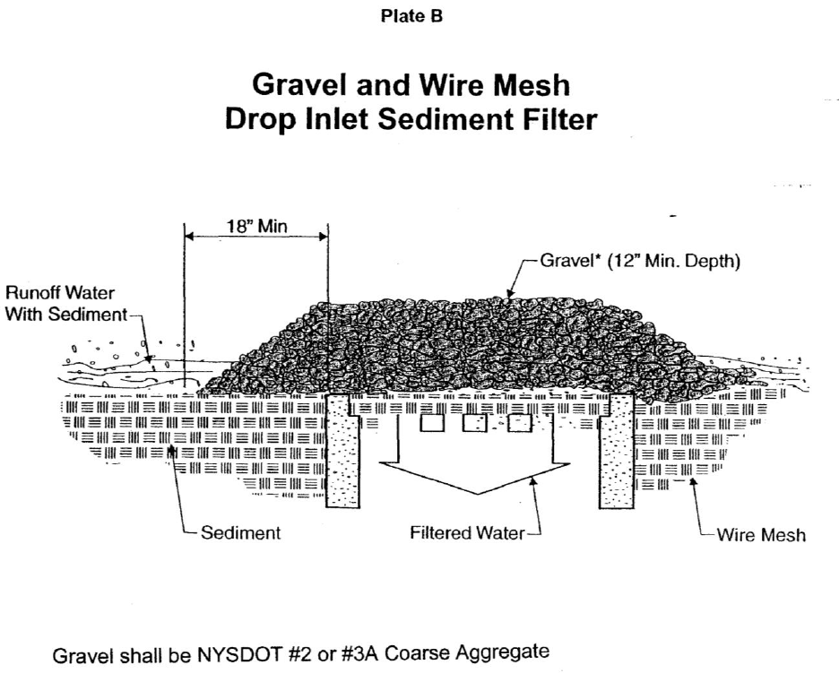
NYC DOT Highway Specifications 650
5/16/2022

NYC DOT Highway Specifications 651
5/16/2022
APPENDIX G – TEMPORARY SEEDING FOR DISTURBED AREAS
A. Description of Work
The Contractor shall furnish all materials, labor and equipment necessary to apply the temporary
seeding mixture to stabilize all areas to be cleared and graded unless they are to be landscaped
or planted in less than thirty 30 days.
B. Materials
1. Seed Mixture. Temporary seeding shall be Ryegrass (annual or perennial) at a
rate of 30 lbs per acre of 0.7 lbs per 1,000 square feet. If area is seeded during
the months of October and November, certified “Aroostook” winter rye (cereal rye)
shall be used at a rate of 100 lbs. per acre of 2.5 lbs per 1,000 square feet.
2. Temporary seeding shall be made within 24 hours of construction/disturbance. If
not, the soil must be scarified prior to seeding.
3. Method of seeding – seed shall be evenly applied with broadcast seeder, drill or
cultipack seeder.
4. If temporary seeding is made under favorable soil and site conditions during the
optimum seeding dates (March 21 – May 20 or August 25 – October 15) mulch is
not required. Any temporary seeding outside of those dates shall be mulched with
salt hay mulch at a rate of 2 tons per acre (100-200 bales/acre).
5. Any area that fails to establish vegetative cover adequate to prevent rill erosion
shall be reseeded as soon as such areas are identified.
