
Compella™ Bariatric Bed System
User Manual
Product No. P7800A
178951 REV 1
Compella™ Bariatric Bed System User Manual (178951 REV 1) i
QUICK VIEW™ LIST OF FEATURES
For more information about a feature, go to the page number shown for the feature in the
tables below.
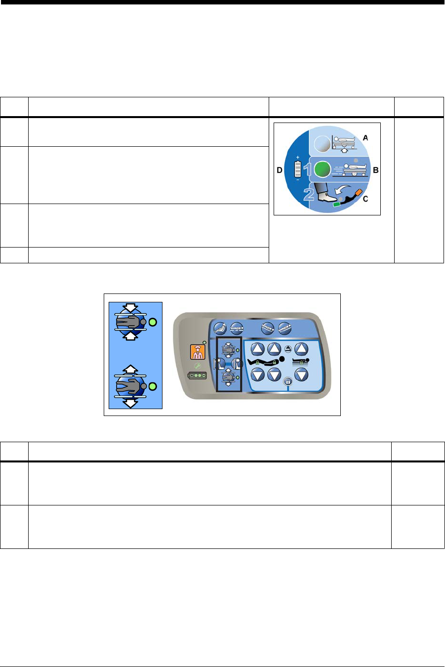
INTELLIDRIVE® XL TRANSPORT SYSTEM—TRANSPORT POD
POWERED WIDTH CONTROLS
Item Feature Page
A Disengage Transport Position—press this
control to raise the drive wheels off the ground.
42
B Transport Position—press this control to lower
the bed to the transport position. Press and hold
this control until the control’s indicator is green
and you hear a single beep.
C Steer Pedal indicator— when this indicator is
green, the bed is in steer mode and can be
moved.
D Battery Charge indicator
Item Feature Page
A Retract—with the siderails raised, press and hold this control to retract
the width of the bed. Press and hold the control until the control’s
indicator is green and you hear a single beep.
39
B Extend—press and hold this control to extend the width of the bed.
Press and hold the control until the control’s indicator is green and you
hear a single beep.
39
A
B

ii Compella™ Bariatric Bed System User Manual (178951 REV 1)
Quick View™ List of Features
CAREGIVER CONTROL POD
NOTE:
There are two scale systems available for the bed, refer to the images and page numbers
shown below to determine which instructions apply to your scale system:
Item Feature Page
A Weigh—press this control to take a weight reading. 53 or 56
B Zero—with the Enable key active, press this control to zero the bed. 52 or 55
C Raise the Bed—the indicator on this control flashes when you attempt
to use a scale control while the bed is in transport position (power drive
wheels on the ground). Press and hold the control until the bed is no
longer in the transport position (the indicator will turn off, and you will
hear a single beep).
52 or 54
D Enable key—when active lets you zero the bed, set the Bed Exit alert, set
the 30° Head Angle alert, and adjust the alert volume and tone.
53
E Bed Exit: Patient Position mode—with the Enable key active, press this
control to set the Bed Exit alert to notify you when the patient begins to
move.
60
F Bed Exit: Bed Exiting mode—with the Enable key active, press this
control to set the Bed Exit alert to notify you when the patient attempts
to get out of the bed.
60
G Bed Exit: Out-of-Bed mode—with the Enable key active, press this
control to set the Bed Exit alert to notify you when the patient has left the
bed.
57 or 60
H Alert Silence—when a Bed Exit alert is armed, press this control to stop
monitoring the patient movement temporarily (30 seconds).
58 or 60
I Alert Volume—with the Enable key active, a patient on the bed, and a
Bed Exit mode armed, press and release this control to adjust the volume
of the alert.
59 or 62
J 30° Head Angle Alert—with the Enable key active, press this control to
be notified when the bed’s head section goes below 30°.
38
K Digital display—shows the head section angle or patient weight. 51 or 54
Scale A Scale B
Refer to page 51. Refer to page 54.

Compella™ Bariatric Bed System User Manual (178951 REV 1) iii
Quick View™ List of Features
L Magnification (Mag) mode—shows the weight in the nearest 0.5 kg. 56
M Frame Setup—puts the bed in the correct position to zero the scale or
weigh the patient.
54
N Release Brake—this indicator flashes if the brakes are set and you
attempt to zero the scale.The brakes need to be released to accurately
zero the scale.
54
O Scale Reference—this indicator comes on solid when the bed is
correctly in the Scale Reference Position.
54
P Zero instructions—shows the sequential steps to zero the scale. 55
Item Feature Page

iv Compella™ Bariatric Bed System User Manual (178951 REV 1)
Quick View™ List of Features
AIR SUPPLY UNIT
The air supply unit has these controls:
• Menu—selects the Menu options.
• Enter—moves to and from the Patient Setup screen.
• Help—shows the Help screen.
• Arrows—select settings on the Patient Setup screen.
Set Up the Air Surface for the Patient (Refer to page 70)
1. At the Pressure Redistribution screen,
press Enter.
2. Use the arrow keys on the right-side of
the display to select Height or Weight.
3. Press Increase or Decrease as applicable
to enter the correct height or weight.
4. The unit automatically adjusts the pressures for the set height and weight. If necessary,
use the arrow keys to move the cursor to the applicable pressure setting: head, seat, or
foot, and use the Increase and Decrease controls to adjust the settings. To return all
pressure settings to the pressures automatically set by the unit for the set height and
weight, press Default.
5. Press Enter to save the pressure settings and return to the Pressure Redistribution
screen.
Menu
Enter Help
Arrows

Compella™ Bariatric Bed System User Manual (178951 REV 1) v
© 2015 by Hill-Rom Services, Inc. ALL RIGHTS RESERVED.
Authorized European Union Representative:
HILL-ROM SAS
B.P. 14 - Z.I. DU TALHOUET
56330 PLUVIGNER
FRANCE
TEL: +33 (0)2 97 50 92 12
Authorized Brazilian Representative:
VR MEDICAL – MEDICAL DEVICES IMPORTER & DISTRIBUTOR, LTDA.
391 BATATAES STREET
CJ 11-13, 8TH FLOOR
SÃO PAULO, SP- BRAZIL
CNPJ: 04.718.143/0001-94
No part of this text shall be reproduced or transmitted in any form or by any means,
electronic or mechanical, including photocopying, recording, or by any information or
retrieval system without written permission from Hill-Rom Services, Inc. (Hill-Rom).
The information in this manual is confidential and may not be disclosed to third parties
without the prior written consent of Hill-Rom.
The information in this manual is subject to change without notice. Hill-Rom makes no
commitment to update or keep current, the information in this manual.
Hill-Rom reserves the right to make changes without notice in design, specifications, and
models. The only warranty Hill-Rom makes is the express written warranty extended on the
sale or rental of its products.
The Compella™ Bariatric Bed product may be covered by one or more patents. For a list of
applicable patents, go to www.hill-rom.com/patents.
This manual (178951) was originally released and supplied in English. For a list of available
translations, contact Hill-Rom Technical Support.
First Edition, March 2015
First Printing, 2015
The UL logo is registered trademark of Underwriter’s Laboratories, Inc.
System Manufactured by:
Bed Frame and Foam Surface
HILL-ROM, INC.
1069 STATE ROUTE 46 E
BATESVILLE, IN 47006-9167 USA
Therapy Surface and Air Supply Unit
TRIDIEN MEDICAL
4200 NW 120 AVENUE
CORAL SPRINGS, FL 33065 USA

vi Compella™ Bariatric Bed System User Manual (178951 REV 1)
Auto Contour™, Compella™, FlexAfoot™, and Quick View™ are trademarks of Hill-Rom
Services, Inc.
Advanced MicroClimate®, Enhancing Outcomes for Patients and Their Caregivers®,
Hill-Rom®, IntelliDrive®, Line-of-Site®, Point-of-Care®, SideCom®, and SlideGuard® are
registered trademarks of Hill-Rom Services, Inc.
Replace this manual (178951) if it is damaged and/or can not be read.
For product support or to order additional copies of this manual (178951), contact your
distributor, local Hill-Rom representative, or go to www.hill-rom.com.
Reference Documents
Compella™ Bariatric Bed System Service Manual (178952)
Compella™ Bariatric Bed Unpacking Instructions (187122)

Compella™ Bariatric Bed System User Manual (178951 REV 1) vii
Table of Contents
Quick View™ List of Features . . . . . . . . . . . . . . . . . . . . . . . . . . . . . . . . . . . . . . . . . . . . . . . . . . . . . i
IntelliDrive® XL Transport System—Transport Pod . . . . . . . . . . . . . . . . . . . . . . . . . . . . i
Powered Width controls . . . . . . . . . . . . . . . . . . . . . . . . . . . . . . . . . . . . . . . . . . . . . . . . . . . . . i
Caregiver Control Pod . . . . . . . . . . . . . . . . . . . . . . . . . . . . . . . . . . . . . . . . . . . . . . . . . . . . . . .ii
Air Supply Unit. . . . . . . . . . . . . . . . . . . . . . . . . . . . . . . . . . . . . . . . . . . . . . . . . . . . . . . . . . . . . . iv
Set Up the Air Surface for the Patient (Refer to page 70) . . . . . . . . . . . . . . . . . . iv
Intended Use. . . . . . . . . . . . . . . . . . . . . . . . . . . . . . . . . . . . . . . . . . . . . . . . . . . . . . . . . . . . . . . . . . . .1
Symbols. . . . . . . . . . . . . . . . . . . . . . . . . . . . . . . . . . . . . . . . . . . . . . . . . . . . . . . . . . . . . . . . . . . . . . . . .2
Product Symbols. . . . . . . . . . . . . . . . . . . . . . . . . . . . . . . . . . . . . . . . . . . . . . . . . . . . . . . . . . . . .2
Acronyms . . . . . . . . . . . . . . . . . . . . . . . . . . . . . . . . . . . . . . . . . . . . . . . . . . . . . . . . . . . . . . . . . . . . . 17
Safety Information. . . . . . . . . . . . . . . . . . . . . . . . . . . . . . . . . . . . . . . . . . . . . . . . . . . . . . . . . . . . . 18
Quick View™ List of Bed Features. . . . . . . . . . . . . . . . . . . . . . . . . . . . . . . . . . . . . . . . . . . . . . . 21
Information Indicators . . . . . . . . . . . . . . . . . . . . . . . . . . . . . . . . . . . . . . . . . . . . . . . . . . . . . . . . . 22
Audible Indicators . . . . . . . . . . . . . . . . . . . . . . . . . . . . . . . . . . . . . . . . . . . . . . . . . . . . . . . . . 22
Brake Not Set . . . . . . . . . . . . . . . . . . . . . . . . . . . . . . . . . . . . . . . . . . . . . . . . . . . . . . . . . . 22
Visual Indicators . . . . . . . . . . . . . . . . . . . . . . . . . . . . . . . . . . . . . . . . . . . . . . . . . . . . . . . . . . . 23
Battery Charge Indicator (for Bed Frame Articulations). . . . . . . . . . . . . . . . . . . 23
Service Required . . . . . . . . . . . . . . . . . . . . . . . . . . . . . . . . . . . . . . . . . . . . . . . . . . . . . . . 23
Bed Not Down . . . . . . . . . . . . . . . . . . . . . . . . . . . . . . . . . . . . . . . . . . . . . . . . . . . . . . . . . 24
Hip Position Locator. . . . . . . . . . . . . . . . . . . . . . . . . . . . . . . . . . . . . . . . . . . . . . . . . . . . 24
Line-of-Site® Head Angle Indicator . . . . . . . . . . . . . . . . . . . . . . . . . . . . . . . . . . . . . . 24
No Equipment Zone. . . . . . . . . . . . . . . . . . . . . . . . . . . . . . . . . . . . . . . . . . . . . . . . . . . . 24
Standard Features . . . . . . . . . . . . . . . . . . . . . . . . . . . . . . . . . . . . . . . . . . . . . . . . . . . . . . . . . . . . . 25
CPR Controls. . . . . . . . . . . . . . . . . . . . . . . . . . . . . . . . . . . . . . . . . . . . . . . . . . . . . . . . . . . . . . . 25
Use the CPR Controls . . . . . . . . . . . . . . . . . . . . . . . . . . . . . . . . . . . . . . . . . . . . . . . . . . . 25
To Deflate an Air Surface . . . . . . . . . . . . . . . . . . . . . . . . . . . . . . . . . . . . . . . . . . . . 25
To Lower the Head of the Bed . . . . . . . . . . . . . . . . . . . . . . . . . . . . . . . . . . . . . . . 25
To Inflate the Air Surface after CPR . . . . . . . . . . . . . . . . . . . . . . . . . . . . . . . . . . 26
Power Cords . . . . . . . . . . . . . . . . . . . . . . . . . . . . . . . . . . . . . . . . . . . . . . . . . . . . . . . . . . . . . . . 26
Cord Hooks . . . . . . . . . . . . . . . . . . . . . . . . . . . . . . . . . . . . . . . . . . . . . . . . . . . . . . . . . . . . . . . . 27
Head and Intermediate Siderails. . . . . . . . . . . . . . . . . . . . . . . . . . . . . . . . . . . . . . . . . . . . 27

viii Compella™ Bariatric Bed System User Manual (178951 REV 1)
Table of Contents
Line-of-Site® Angle Indicators . . . . . . . . . . . . . . . . . . . . . . . . . . . . . . . . . . . . . . . . . . . 28
To Lower a Siderail. . . . . . . . . . . . . . . . . . . . . . . . . . . . . . . . . . . . . . . . . . . . . . . . . . . . . . 28
To Raise a Siderail . . . . . . . . . . . . . . . . . . . . . . . . . . . . . . . . . . . . . . . . . . . . . . . . . . . . . . .28
Point of Care® Bed Controls . . . . . . . . . . . . . . . . . . . . . . . . . . . . . . . . . . . . . . . . . . . . . . . . . 29
Standard Patient Controls . . . . . . . . . . . . . . . . . . . . . . . . . . . . . . . . . . . . . . . . . . . . . . . 29
Head Up/Down . . . . . . . . . . . . . . . . . . . . . . . . . . . . . . . . . . . . . . . . . . . . . . . . . . . . . 29
Knee Up/Down. . . . . . . . . . . . . . . . . . . . . . . . . . . . . . . . . . . . . . . . . . . . . . . . . . . . . . 30
Standard Caregiver Controls on the Siderails. . . . . . . . . . . . . . . . . . . . . . . . . . . . . 30
Lockout. . . . . . . . . . . . . . . . . . . . . . . . . . . . . . . . . . . . . . . . . . . . . . . . . . . . . . . . . . . . .31
Bed Up/Down. . . . . . . . . . . . . . . . . . . . . . . . . . . . . . . . . . . . . . . . . . . . . . . . . . . . . . . 32
Head Up/Down . . . . . . . . . . . . . . . . . . . . . . . . . . . . . . . . . . . . . . . . . . . . . . . . . . . . . 33
Knee Up/Down. . . . . . . . . . . . . . . . . . . . . . . . . . . . . . . . . . . . . . . . . . . . . . . . . . . . . . 33
Tilt and Reverse Tilt. . . . . . . . . . . . . . . . . . . . . . . . . . . . . . . . . . . . . . . . . . . . . . . . . . 33
Bed Flat . . . . . . . . . . . . . . . . . . . . . . . . . . . . . . . . . . . . . . . . . . . . . . . . . . . . . . . . . . . . .34
Cardiac Chair. . . . . . . . . . . . . . . . . . . . . . . . . . . . . . . . . . . . . . . . . . . . . . . . . . . . . . . . 34
Battery Back-Up. . . . . . . . . . . . . . . . . . . . . . . . . . . . . . . . . . . . . . . . . . . . . . . . . . . . . . . . .34
Brake and Steer Controls . . . . . . . . . . . . . . . . . . . . . . . . . . . . . . . . . . . . . . . . . . . . . . . . 35
To Activate. . . . . . . . . . . . . . . . . . . . . . . . . . . . . . . . . . . . . . . . . . . . . . . . . . . . . . . . . . 36
Patient Restraint and Drainage Bag Holders. . . . . . . . . . . . . . . . . . . . . . . . . . . . . . 36
Patient Restraints . . . . . . . . . . . . . . . . . . . . . . . . . . . . . . . . . . . . . . . . . . . . . . . . . . . 36
Drainage Bag Holders . . . . . . . . . . . . . . . . . . . . . . . . . . . . . . . . . . . . . . . . . . . . . . . 37
Equipment Sockets . . . . . . . . . . . . . . . . . . . . . . . . . . . . . . . . . . . . . . . . . . . . . . . . . . . . . 37
Night Light . . . . . . . . . . . . . . . . . . . . . . . . . . . . . . . . . . . . . . . . . . . . . . . . . . . . . . . . . . . . . 38
Head Angle Digital Display . . . . . . . . . . . . . . . . . . . . . . . . . . . . . . . . . . . . . . . . . . . . . . 38
30° Head Angle Alert. . . . . . . . . . . . . . . . . . . . . . . . . . . . . . . . . . . . . . . . . . . . . . . . . . . . 38
Set the Alert. . . . . . . . . . . . . . . . . . . . . . . . . . . . . . . . . . . . . . . . . . . . . . . . . . . . . . . . . 38
Respond to the Alert . . . . . . . . . . . . . . . . . . . . . . . . . . . . . . . . . . . . . . . . . . . . . . . . 38
Deactivate the Alert . . . . . . . . . . . . . . . . . . . . . . . . . . . . . . . . . . . . . . . . . . . . . . . . . 38
Bed Width Adjustment . . . . . . . . . . . . . . . . . . . . . . . . . . . . . . . . . . . . . . . . . . . . . . . . . . 39
Powered Width Controls. . . . . . . . . . . . . . . . . . . . . . . . . . . . . . . . . . . . . . . . . . . . . 39
Manual Width Control . . . . . . . . . . . . . . . . . . . . . . . . . . . . . . . . . . . . . . . . . . . . . . . 40
FlexAfoot™ Bed Length Adjustment . . . . . . . . . . . . . . . . . . . . . . . . . . . . . . . . . . . . . 41
Equipotential Ground . . . . . . . . . . . . . . . . . . . . . . . . . . . . . . . . . . . . . . . . . . . . . . . . . . . 42
Patient Transport . . . . . . . . . . . . . . . . . . . . . . . . . . . . . . . . . . . . . . . . . . . . . . . . . . . . . . . . . . . . . . 42

Compella™ Bariatric Bed System User Manual (178951 REV 1) ix
Table of Contents
Intellidrive® XL Transport System . . . . . . . . . . . . . . . . . . . . . . . . . . . . . . . . . . . . . . . . . . . 42
Transport Pod . . . . . . . . . . . . . . . . . . . . . . . . . . . . . . . . . . . . . . . . . . . . . . . . . . . . . . . . . . . . . 42
To Prepare the Bed for Transport. . . . . . . . . . . . . . . . . . . . . . . . . . . . . . . . . . . . . . . . 44
Engage Transport Mode . . . . . . . . . . . . . . . . . . . . . . . . . . . . . . . . . . . . . . . . . . . . . . . . 46
Transport . . . . . . . . . . . . . . . . . . . . . . . . . . . . . . . . . . . . . . . . . . . . . . . . . . . . . . . . . . . . . . 46
Disengage Transport Mode . . . . . . . . . . . . . . . . . . . . . . . . . . . . . . . . . . . . . . . . . . . . . 47
Non-Powered Transport. . . . . . . . . . . . . . . . . . . . . . . . . . . . . . . . . . . . . . . . . . . . . . . . . . . . 48
Transport a Patient . . . . . . . . . . . . . . . . . . . . . . . . . . . . . . . . . . . . . . . . . . . . . . . . . . . . . 49
Scale Systems . . . . . . . . . . . . . . . . . . . . . . . . . . . . . . . . . . . . . . . . . . . . . . . . . . . . . . . . . . . . . . . . . 51
Scale “A” Display . . . . . . . . . . . . . . . . . . . . . . . . . . . . . . . . . . . . . . . . . . . . . . . . . . . . . . . . . . 51
Bed Setup. . . . . . . . . . . . . . . . . . . . . . . . . . . . . . . . . . . . . . . . . . . . . . . . . . . . . . . . . . . . . . 52
To Zero the Scale . . . . . . . . . . . . . . . . . . . . . . . . . . . . . . . . . . . . . . . . . . . . . . . . . . . 52
Weigh the Patient . . . . . . . . . . . . . . . . . . . . . . . . . . . . . . . . . . . . . . . . . . . . . . . . . . . . . . 53
Changing the Scale Units . . . . . . . . . . . . . . . . . . . . . . . . . . . . . . . . . . . . . . . . . . . . . . . 53
Scale “B” Display . . . . . . . . . . . . . . . . . . . . . . . . . . . . . . . . . . . . . . . . . . . . . . . . . . . . . . . . . . . 54
Bed Setup. . . . . . . . . . . . . . . . . . . . . . . . . . . . . . . . . . . . . . . . . . . . . . . . . . . . . . . . . . . . . . 54
Scale Reference Position. . . . . . . . . . . . . . . . . . . . . . . . . . . . . . . . . . . . . . . . . . . . . . . . 54
To Zero the Scale . . . . . . . . . . . . . . . . . . . . . . . . . . . . . . . . . . . . . . . . . . . . . . . . . . . 55
Weigh the Patient . . . . . . . . . . . . . . . . . . . . . . . . . . . . . . . . . . . . . . . . . . . . . . . . . . . . . . 56
Magnification (Mag) Mode. . . . . . . . . . . . . . . . . . . . . . . . . . . . . . . . . . . . . . . . . . . . . . 56
Unstable Weight . . . . . . . . . . . . . . . . . . . . . . . . . . . . . . . . . . . . . . . . . . . . . . . . . . . . . . . 56
Single Mode Bed Exit Alert System . . . . . . . . . . . . . . . . . . . . . . . . . . . . . . . . . . . . . . . . . . . . . 57
To Activate the Bed Exit Alert System . . . . . . . . . . . . . . . . . . . . . . . . . . . . . . . . . . . . . . . 57
To Silence the Bed Exit Alert System without Deactivating the System . . . . . . . 58
To Deactivate the Bed Exit Alert System . . . . . . . . . . . . . . . . . . . . . . . . . . . . . . . . . . . . 59
To Adjust the Alert Volume. . . . . . . . . . . . . . . . . . . . . . . . . . . . . . . . . . . . . . . . . . . . . . . . . 59
To Change the Alert Tone . . . . . . . . . . . . . . . . . . . . . . . . . . . . . . . . . . . . . . . . . . . . . . . . . . 59
Three-Mode Bed Exit Alert System . . . . . . . . . . . . . . . . . . . . . . . . . . . . . . . . . . . . . . . . . . . . . 60
To Activate the Bed Exit Alert System . . . . . . . . . . . . . . . . . . . . . . . . . . . . . . . . . . . . . . . 61
To Silence the Bed Exit Alert System without Deactivating the System . . . . . . . 61
To Deactivate the Bed Exit Alert System . . . . . . . . . . . . . . . . . . . . . . . . . . . . . . . . . . . . 62
To Adjust the Alert Volume. . . . . . . . . . . . . . . . . . . . . . . . . . . . . . . . . . . . . . . . . . . . . . . . . 62
To Change the Alert Tone . . . . . . . . . . . . . . . . . . . . . . . . . . . . . . . . . . . . . . . . . . . . . . . . . . 62
SideCom® Communication System. . . . . . . . . . . . . . . . . . . . . . . . . . . . . . . . . . . . . . . . . . . . . 63

x Compella™ Bariatric Bed System User Manual (178951 REV 1)
Table of Contents
Nurse Call Control . . . . . . . . . . . . . . . . . . . . . . . . . . . . . . . . . . . . . . . . . . . . . . . . . . . . . . . . . . 63
To Activate. . . . . . . . . . . . . . . . . . . . . . . . . . . . . . . . . . . . . . . . . . . . . . . . . . . . . . . . . . 63
Surface Features and Controls . . . . . . . . . . . . . . . . . . . . . . . . . . . . . . . . . . . . . . . . . . . . . . . . . .64
Safety Information. . . . . . . . . . . . . . . . . . . . . . . . . . . . . . . . . . . . . . . . . . . . . . . . . . . . . . . . . . 64
Support Surface Options. . . . . . . . . . . . . . . . . . . . . . . . . . . . . . . . . . . . . . . . . . . . . . . . . . . . 66
Install the Surface and Air Supply Unit. . . . . . . . . . . . . . . . . . . . . . . . . . . . . . . . . . . . . . . 66
Air Supply Unit . . . . . . . . . . . . . . . . . . . . . . . . . . . . . . . . . . . . . . . . . . . . . . . . . . . . . . . . . . . . . 69
Compella™ Therapy Surface. . . . . . . . . . . . . . . . . . . . . . . . . . . . . . . . . . . . . . . . . . . . . . . . . 70
Set Up the Unit for the Patient. . . . . . . . . . . . . . . . . . . . . . . . . . . . . . . . . . . . . . . . . . . 70
Surface Options. . . . . . . . . . . . . . . . . . . . . . . . . . . . . . . . . . . . . . . . . . . . . . . . . . . . . . . . .71
Max Inflate Mode. . . . . . . . . . . . . . . . . . . . . . . . . . . . . . . . . . . . . . . . . . . . . . . . . . . . 71
Fowler Boost Mode. . . . . . . . . . . . . . . . . . . . . . . . . . . . . . . . . . . . . . . . . . . . . . . . . . 71
Lock or Unlock the Control Panel . . . . . . . . . . . . . . . . . . . . . . . . . . . . . . . . . . . . . . . .72
Turn Assist Mode . . . . . . . . . . . . . . . . . . . . . . . . . . . . . . . . . . . . . . . . . . . . . . . . . . . . . . . 72
Deflate and Inflate the Seat Section for Patient Exit or Entry . . . . . . . . . . . . . . 74
Continuous Lateral Rotation Therapy (CLRT) Mode . . . . . . . . . . . . . . . . . . . . . . . 74
Deflate and Inflate the Side Bolsters and Foot Section . . . . . . . . . . . . . . . . . . . . 76
Automatically (using the Caregiver Width Adjust controls). . . . . . . . . . . . 76
Manually (using the Air Supply Unit) . . . . . . . . . . . . . . . . . . . . . . . . . . . . . . . . . 76
Deflate the Side Bolsters and Foot Section for Patient Transport . . . . . . . . . . 78
Compella™ Foam Surface with Inflatable Side Bolsters . . . . . . . . . . . . . . . . . . . . . . . 79
Deflate and Inflate the Side Bolsters and Foot Section . . . . . . . . . . . . . . . . . . . . 79
Automatically (using the Caregiver Width Adjust controls). . . . . . . . . . . . 79
Manually (using the Air Supply Unit) . . . . . . . . . . . . . . . . . . . . . . . . . . . . . . . . . 79
Deflate and Inflate the Side Bolsters and Foot Section for
Patient Transport . . . . . . . . . . . . . . . . . . . . . . . . . . . . . . . . . . . . . . . . . . . . . . . . . . . . . . . 81
Air Supply Unit—Informational Tones . . . . . . . . . . . . . . . . . . . . . . . . . . . . . . . . . . . 81
Accessories . . . . . . . . . . . . . . . . . . . . . . . . . . . . . . . . . . . . . . . . . . . . . . . . . . . . . . . . . . . . . . . . . . . . 82
Accessories for North America . . . . . . . . . . . . . . . . . . . . . . . . . . . . . . . . . . . . . . . . . . . . . . 83
IV Pole (P2217A) . . . . . . . . . . . . . . . . . . . . . . . . . . . . . . . . . . . . . . . . . . . . . . . . . . . . . . . .83
To Install . . . . . . . . . . . . . . . . . . . . . . . . . . . . . . . . . . . . . . . . . . . . . . . . . . . . . . . . . . . .83
To Remove. . . . . . . . . . . . . . . . . . . . . . . . . . . . . . . . . . . . . . . . . . . . . . . . . . . . . . . . . . 83
Oxygen Tank Holder, Vertical (P27601) . . . . . . . . . . . . . . . . . . . . . . . . . . . . . . . . . . 83
To Install . . . . . . . . . . . . . . . . . . . . . . . . . . . . . . . . . . . . . . . . . . . . . . . . . . . . . . . . . . . .83

Compella™ Bariatric Bed System User Manual (178951 REV 1) xi
Table of Contents
To Remove . . . . . . . . . . . . . . . . . . . . . . . . . . . . . . . . . . . . . . . . . . . . . . . . . . . . . . . . . 84
Patient Helper (P7802A) . . . . . . . . . . . . . . . . . . . . . . . . . . . . . . . . . . . . . . . . . . . . . . . . 84
To Install . . . . . . . . . . . . . . . . . . . . . . . . . . . . . . . . . . . . . . . . . . . . . . . . . . . . . . . . . . . 85
To Remove . . . . . . . . . . . . . . . . . . . . . . . . . . . . . . . . . . . . . . . . . . . . . . . . . . . . . . . . . 85
Patient Pendant (P7803A01/02). . . . . . . . . . . . . . . . . . . . . . . . . . . . . . . . . . . . . . . . . 85
To Install . . . . . . . . . . . . . . . . . . . . . . . . . . . . . . . . . . . . . . . . . . . . . . . . . . . . . . . . . . . 85
To Remove . . . . . . . . . . . . . . . . . . . . . . . . . . . . . . . . . . . . . . . . . . . . . . . . . . . . . . . . . 86
Pressure Transducer Holder (P3670A05) and Respiratory Circuit
Holder (P3670A01) . . . . . . . . . . . . . . . . . . . . . . . . . . . . . . . . . . . . . . . . . . . . . . . . . . . . . 86
To Install . . . . . . . . . . . . . . . . . . . . . . . . . . . . . . . . . . . . . . . . . . . . . . . . . . . . . . . . . . . 86
Infusion Support System (P158A) . . . . . . . . . . . . . . . . . . . . . . . . . . . . . . . . . . . . . . . 87
Headboard (P7801A01). . . . . . . . . . . . . . . . . . . . . . . . . . . . . . . . . . . . . . . . . . . . . . . . . 87
To Remove . . . . . . . . . . . . . . . . . . . . . . . . . . . . . . . . . . . . . . . . . . . . . . . . . . . . . . . . . 87
To install . . . . . . . . . . . . . . . . . . . . . . . . . . . . . . . . . . . . . . . . . . . . . . . . . . . . . . . . . . . 87
Line Managers (P7512A) . . . . . . . . . . . . . . . . . . . . . . . . . . . . . . . . . . . . . . . . . . . . . . . . 88
Accessories for International . . . . . . . . . . . . . . . . . . . . . . . . . . . . . . . . . . . . . . . . . . . . . . . 88
IV Pole Adapter (71438). . . . . . . . . . . . . . . . . . . . . . . . . . . . . . . . . . . . . . . . . . . . . . . . . 88
Oxygen Tank Holders (AC959A, AD101A, and AD102A) . . . . . . . . . . . . . . . . . . 88
Pivoting 3-Liter Cylinder holder (AC962A) . . . . . . . . . . . . . . . . . . . . . . . . . . . . . . . 89
Telescopic IV Poles (AD165A and AD148A) . . . . . . . . . . . . . . . . . . . . . . . . . . . . . . 89
To Use the IV Pole with Four Hooks (AD165A). . . . . . . . . . . . . . . . . . . . . . . . 90
To Use the IV Pole with Two Hooks (AD148A) . . . . . . . . . . . . . . . . . . . . . . . . 90
Syringe-Driver Holder (AC963A) . . . . . . . . . . . . . . . . . . . . . . . . . . . . . . . . . . . . . . . . 90
To Adjust the Holder Position . . . . . . . . . . . . . . . . . . . . . . . . . . . . . . . . . . . . . . . 91
Cleaning/disinfecting. . . . . . . . . . . . . . . . . . . . . . . . . . . . . . . . . . . . . . . . . . . . . . . . . . . . . . . . . . 91
support Surface Component Identification . . . . . . . . . . . . . . . . . . . . . . . . . . . . . . . . . 91
Recommendations. . . . . . . . . . . . . . . . . . . . . . . . . . . . . . . . . . . . . . . . . . . . . . . . . . . . . . . . . 92
Clean and Disinfect the Bed, Air Supply unit, and support Surface . . . . . . . . . . . 93
Machine Wash the Topper . . . . . . . . . . . . . . . . . . . . . . . . . . . . . . . . . . . . . . . . . . . . . . . . . 94
Clean the Air Supply Unit Filters . . . . . . . . . . . . . . . . . . . . . . . . . . . . . . . . . . . . . . . . . . . . 95
Preventive Maintenance . . . . . . . . . . . . . . . . . . . . . . . . . . . . . . . . . . . . . . . . . . . . . . . . . . . . . . . 96
Batteries. . . . . . . . . . . . . . . . . . . . . . . . . . . . . . . . . . . . . . . . . . . . . . . . . . . . . . . . . . . . . . . . . . . 96
Bed Frame . . . . . . . . . . . . . . . . . . . . . . . . . . . . . . . . . . . . . . . . . . . . . . . . . . . . . . . . . . . . . 97
IntelliDrive® XL Transport System . . . . . . . . . . . . . . . . . . . . . . . . . . . . . . . . . . . . . . . 97

xii Compella™ Bariatric Bed System User Manual (178951 REV 1)
Table of Contents
Air Supply Unit—Filters Replacement . . . . . . . . . . . . . . . . . . . . . . . . . . . . . . . . . . . . . . . 97
Troubleshooting . . . . . . . . . . . . . . . . . . . . . . . . . . . . . . . . . . . . . . . . . . . . . . . . . . . . . . . . . . . . . . . 98
Solve a System Alarm Condition on a Compella™ Therapy Surface. . . . . . . . . . . . 98
Solve a System Alarm Condition on a Compella™ Foam Surface . . . . . . . . . . . . . . 99
Surface and Air Supply Unit—Power Failure and Alarm Conditions. . . . . . . . . .100
Power Failure . . . . . . . . . . . . . . . . . . . . . . . . . . . . . . . . . . . . . . . . . . . . . . . . . . . . . . . . . .100
Alarm/Alert System . . . . . . . . . . . . . . . . . . . . . . . . . . . . . . . . . . . . . . . . . . . . . . . . . . . .100
Notification Priority . . . . . . . . . . . . . . . . . . . . . . . . . . . . . . . . . . . . . . . . . . . . . . . .100
Powered Width Extensions will Not Extend or Retract. . . . . . . . . . . . . . . . . . . . . . .102
The Head section will not Rise or lower. . . . . . . . . . . . . . . . . . . . . . . . . . . . . . . . . . . . .103
The bed CPR handle does not return to the disengaged Position . . . . . . . . . . . .103
Service Calls . . . . . . . . . . . . . . . . . . . . . . . . . . . . . . . . . . . . . . . . . . . . . . . . . . . . . . . . . . . . . . . . . .103
Specifications . . . . . . . . . . . . . . . . . . . . . . . . . . . . . . . . . . . . . . . . . . . . . . . . . . . . . . . . . . . . . . . . .104

Compella™ Bariatric Bed System User Manual (178951 REV 1) 1
Intended Use
INTENDED USE
WARNING:
Do not use the Compella™ Bariatric Bed System with patients who weigh less than 113 kg
(250 lb) or more than 454 kg (1000 lb). Patient injury or equipment damage could occur.
WARNING:
CONTRAINDICATION: Use of powered air surfaces for patients with unstabilized spinal
cord injury could cause serious injury to the patient.
The Compella™ Bariatric Bed System is for bariatric patients of all age groups with varying
medical and physical conditions. The Compella™ Bariatric Bed System is intended to be
used to treat or prevent pulmonary or other complications associated with immobility; to
treat or prevent pressure ulcers; or for any other use where medical benefits may be
derived from Continuous Lateral Rotation Therapy (CLRT). The bed has an expandable
surface and supports patient weights between 113 kg and 454 kg (250 lb and 1000 lb).
The intended users of the Compella™ Bariatric Bed System are healthcare employees who
have the physical strength and cognitive skills to operate and control the bed. Follow
facility safety protocols if an intended user does not have the physical strength or cognitive
skills to operate and control the bed.
This manual contains information necessary for normal operation of the Compella™
Bariatric Bed, Compella™ Therapy Surface, and Compella™ Foam Surface from Hill-Rom.
Before you operate the bed, make sure you read and understand in detail the contents of
this manual. It is important that you read and obey the aspects of safety contained in this
manual.
Any reference to a side of the bed is from the patient’s view lying in the bed on his or her
back.
The bed is equipped with a scale intended to weigh the patient in the bed.
To identify which model of bed you have, look at the serial number label. The label is under
the foot end of the bed.
For example, PXXXXMXXXX identifies an M model bed.

2 Compella™ Bariatric Bed System User Manual (178951 REV 1)
Symbols
SYMBOLS
This manual contains different typefaces and symbols to make the content easier to read
and understand:
• Standard text—used for regular data.
• Boldface text—emphasizes a word or phrase.
• NOTE:—sets apart special data or important instruction clarification.
• WARNING or CAUTION
– A WARNING identifies situations or actions that may have an effect on patient or
user safety. To ignore a warning could cause patient or user injury.
– A CAUTION identifies special procedures or precautions that persons must obey
to help prevent equipment damage.
PRODUCT SYMBOLS
Symbol Description
CPR
CPR instruction label—shows how to operate the CPR
function on the air supply unit (1) and bed frame (2)
(page 25)
CPR mechanism label for the air surface—shows the
direction to turn the CPR mechanism to deflate the
surface (page 25)
CPR control label for the bed frame—shows how to
operate the CPR control to lower the head section (page
25)

Compella™ Bariatric Bed System User Manual (178951 REV 1) 3
Symbols
Caregiver Control Panel
Nurse Call control (page 63)
Service Required indicator (page 23)
Bed battery charge status (page 23)
Chair position control (page 34)
Bed flat control (page 34)
Tilt control (page 33)
Reverse tilt control (page 33)
Width retract control and indicator (page 39)
Symbol Description

4 Compella™ Bariatric Bed System User Manual (178951 REV 1)
Symbols
Width extend control and indicator (page 39)
FlexAfoot™ bed length adjustment (page 41)
Bed Up and Down controls (page 32)
Bed Not Down indicator—comes on when the upper
frame is not in the lowest position (page 24)
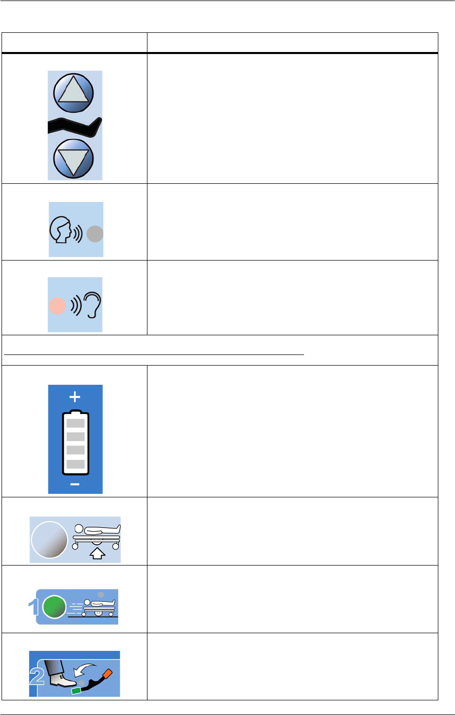
Head Up and Down controls (page 33)
Knee Up and Down control (page 33)
Symbol Description

Compella™ Bariatric Bed System User Manual (178951 REV 1) 5
Symbols
Lockout control—Lock out articulation controls (page
31)
Caregiver Control Pod
Scale Weigh control (page 53 and page 56)
Zero control (page 52)
Zero control—Scale B (page 55)
Magnification Mode control—Scale B (page 56)
Frame Setup control and indicator—Scale B (page 54)
Raise Bed control and indicator—Scale B (page 54)
Scale Reference indicator—Scale B (page 54)
Symbol Description

6 Compella™ Bariatric Bed System User Manual (178951 REV 1)
Symbols
Release Brake indicator—Scale B (page 54)
30° Head Angle Alert control (page 38)
Raise Bed control and indicator (page 52)
Alert Silence control and indicator (page 58 and page 60)
Enable key (page 51, page 57, and page 60)
Bed Exit Alert System—Patient Position mode (page 60)
Bed Exit Alert System—Bed Exiting mode (page 60)
Bed Exit Alert System—Out-of-Bed mode (page 57 and
page 60)
Symbol Description

Compella™ Bariatric Bed System User Manual (178951 REV 1) 7
Symbols
Bed Exit Alert System Volume and Tone Control (page 59
and page 62)
Indicators on the Siderails
Hip Position Locator (page 24)
Tilt/Reverse Tilt angle (page 24)
Head angle (page 24)
Patient Controls
Nurse Call control (page 63)
Head Up and Down controls (page 33)
Symbol Description
8 Compella™ Bariatric Bed System User Manual (178951 REV 1)
Symbols
Knee Up and Down controls (page 33)
Nurse Call Voice indicator (page 63)
Nurse Call Listening indicator (page 63)
IntelliDrive® XL Transport System Transport Pod
IntelliDrive Battery Charge indicator (page 42)
Disengage Transport Position control—raises the bed so
the drive wheels raise off the ground (page 42)
Transport Position control and indicator—lowers the bed
to the transport position (the drive wheels are on the
ground) (page 42)
Steer pedal indicator (page 42)
Symbol Description

Compella™ Bariatric Bed System User Manual (178951 REV 1) 9
Symbols
Bed Frame
Shows how to raise the push handles (page 42 or 48)
Shows how to stow the push handles (page 42 or 48)
Before Transport sequence (page 42)
After Transport sequence (page 42)
Identifies the manual width adjustment control (page 40)
Identifies patient restraint location—chest (page 36)
Identifies patient restraint location—waist/wrist (page
36)
Identifies patient restraint location—ankle (page 36)
Head-end brake pedal (page 35)
Head-end steer pedal (page 35)
Symbol Description

10 Compella™ Bariatric Bed System User Manual (178951 REV 1)
Symbols
Do not use the IV pole in this location
Do not store cords here
Crush warning: must consult accompanying documents
Identifies battery installation location
Identifies mains fuse
Refer to the bed manufacturer’s user manual for
compatible support surfaces (page 64)
Warning: No equipment storage
Do Not Use with Oxygen Tents (green background -
North America; blue background - International)
Symbol Description

Compella™ Bariatric Bed System User Manual (178951 REV 1) 11
Symbols
Identifies the bed power cord (North America)
Identifies the bed power cord (International)
No Equipment Zone
Safe Working Load for the bed (this includes the weight
of the patient, support surface, and accessories that are
on the bed)
Patient minimum and maximum weight range
Patient minimum and maximum weight range
Total bed weight (including the safe working load) (the
bed weight excluding the safe working load is 450 kg
(992 lb) minimum)
Support Surface
Shows the support surface dimensions
Do not iron
Symbol Description

12 Compella™ Bariatric Bed System User Manual (178951 REV 1)
Symbols
Hand wash only
Bleach with specification
Bleach as needed
Do not dry clean
Do not tumble dry
Tumble dry no heat
Drip dry
Machine wash
Symbol Description

Compella™ Bariatric Bed System User Manual (178951 REV 1) 13
Symbols
Safe working load
Air Supply Unit
Identifies the unit as a continuous lateral rotation therapy
unit (page 70)
Air supply unit controls (page 69)
Alarm paused
Product weight
Other
Model number
Serial number
Authorized representative in the European Community
(Therapy surface and air supply unit only) Conforms to
European Medical Device Directive (The BSI CE mark was
first applied in 2015)
Symbol Description
SN

14 Compella™ Bariatric Bed System User Manual (178951 REV 1)
Symbols
(Compella™ Bariatric Bed System) Conforms to European
Medical Device Directive 93/42/EEC (The UL CE mark was
first applied in 2015)
Conforms to European Medical Device Directive
93/42/EEC (NAWI EN45501scale) (XX identifies the date of
manufacture) (The CE mark was first applied in 2015)
Black M on green background—signifies the scale
(NAWI EN45501 only) is certified to weigh in approved
positions)
Scale class identifier—identifies the scale as EN45501
Class III
(Bed only) Medical Electrical Equipment Classified By
Underwriters Laboratories Inc. with respect to Electric
Shock, Fire, Mechanical and other specified Hazards only
in accordance with ES60601-1, IEC/EN60601-1,
IEC/EN60601-2-52, and CAN/CSA C22.2 No. 60601-1
(Therapy surface and air supply unit only) Medical
Electrical Equipment Classified By Underwriters
Laboratories Inc. with respect to Electric Shock, Fire,
Mechanical and other specified Hazards only in
accordance with ES60601-1, IEC/EN60601-1, and
CAN/CSA C22.2 No. 60601-1
Type B applied part according to IEC 60601-1
(Support surface only) Type BF applied part
Symbol Description
III
4PR9
11JR

Compella™ Bariatric Bed System User Manual (178951 REV 1) 15
Symbols
(Bed and patient pendant only) According to IEC 60529,
Rating for protection against fluid ingress and identified
as equipment that is protected against spraying and
splashing water
(Therapy surface and air supply unit only) According to
IEC 60529, Rating for protection against access to
hazardous parts by a finger
ATTENTION: Consult accompanying documents
Manufacturer
Do not dispose as Unsorted Municipal Waste
WARNING (yellow and black)
CAUTION (white and black)
Must consult the accompanying documents
Symbol Description
16 Compella™ Bariatric Bed System User Manual (178951 REV 1)
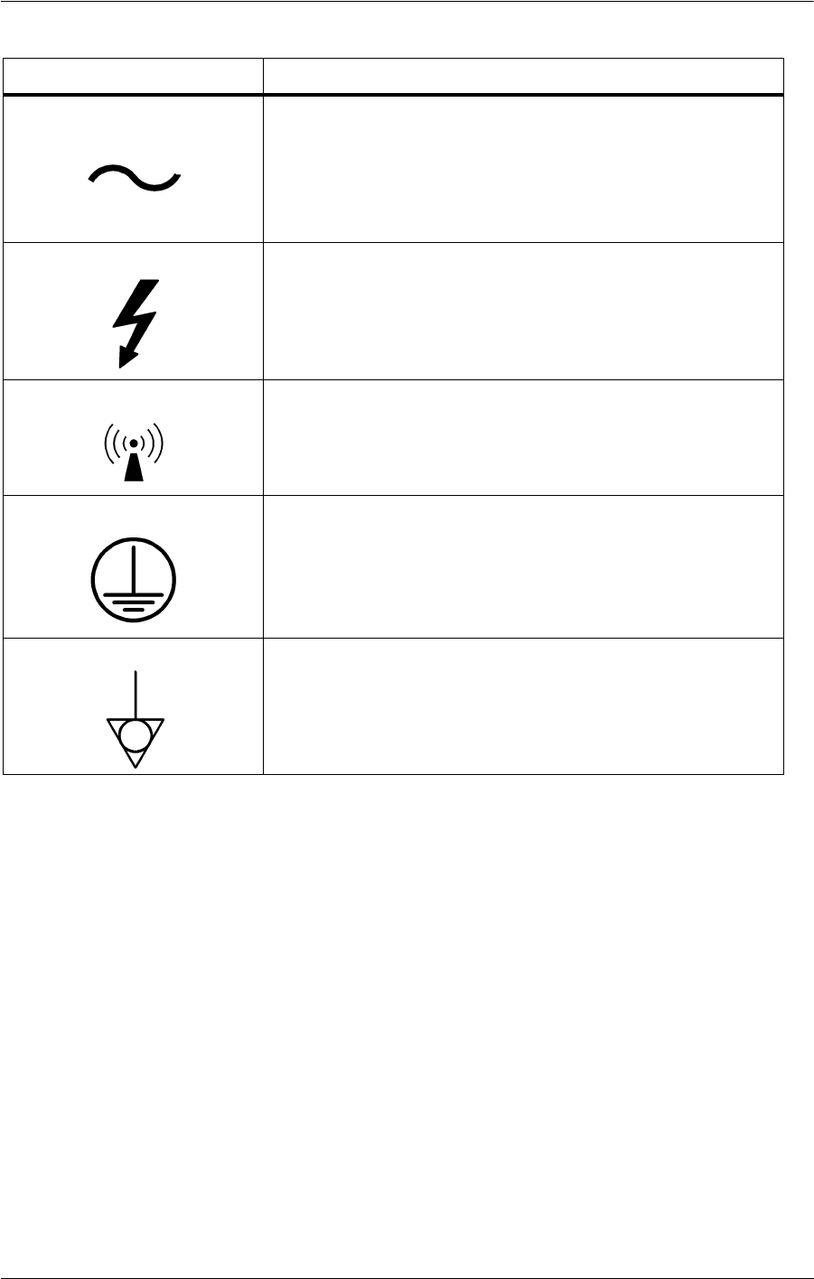
Symbols
Alternating current
Dangerous voltage
Equipment emits electromagnetic energy
Protective Earth
Equipotentiality
Symbol Description

Compella™ Bariatric Bed System User Manual (178951 REV 1) 17
Acronyms
ACRONYMS
Acronym Description
BSI British Standards Institute
CLRT Continuous Lateral Rotation Therapy
CPR Cardio Pulmonary Resuscitation
EPA Environmental Protection Agency
HOB Head of Bed
IFP Interface Pressure (between surface and patient)
LAL Low Airloss
NAWI Non-Automatic Weighing Instrument
PM Preventive Maintenance
RoHS Hazardous Substances Regulation
SWL Safe Working Load
UL Underwriter’s Laboratories, Inc.
WEEE Waste Electrical and Electronic Equipment

18 Compella™ Bariatric Bed System User Manual (178951 REV 1)
Safety Information
SAFETY INFORMATION
For additional warnings and cautions in regard to the therapy surface and air supply unit,
see “Surface Features and Controls” on page 64.
WARNING:
Obey all warnings and cautions throughout the manual and also the safety information
below to help prevent injury and/or equipment damage:
• Read and understand the instructions and safety precautions in this manual and on
the unit itself prior to use with a patient.
• CONTRAINDICATION: Use of active therapy surfaces for patients with unstabilized
spinal cord injury could cause serious injury to the patient.
• Monitor the patient and the patient’s skin condition at regular intervals according
to established clinical assessment protocols.
• A sound risk assessment and protocol is necessary to determine the appropriate
surface for the patient’s condition.
•Do not use the bed with patients who weigh more than 454 kg (1000 lb) or are
wider than the fully-extended surface width. Injury or damage could occur.
• Air pressure in the support surface is controlled automatically and may adjust
without notice. Use care when you perform medical procedures on the patient.
• Do not use the support surface on a bed frame other than the Compella™ Bed
frame. The surface may not fit as intended and could cause a risk of patient
entrapment.
• The hose sleeve on the air supply unit is a safety feature. Do not operate the device
without the hose sleeve installed.
• There is a risk of entanglement that could cause risk of asphyxiation if the hose
sleeve is removed from the hoses.
• Do not transfer the patient from one bed frame to another using the support
surface with a patient on it.
• Use a minimum of two caregivers to transfer a patient on to the support surface.
The caregivers must be in positions where they can control the patient’s position.
• When you put a patient on to the support surface, make sure that the opposite
siderails are raised or that another caregiver is present on the opposite side.
• Do not operate the bed in the presence of flammable gas or vapors.
• Do not operate the bed in the presence of flammable anesthetics or nitrous oxide.
• Do not use the bed in an oxygen rich environment or with oxygen tents.
• Operate the bed within the stated environmental conditions; see “Environmental
Conditions for Use” on page 105.
• Use care when you handle or transport the air supply unit. If the unit is dropped or
receives a sudden impact, equipment damage could occur.

Compella™ Bariatric Bed System User Manual (178951 REV 1) 19
Safety Information
• After exposure to extreme high or low temperatures, let the air supply unit
equilibrate for at least one hour before use.
• The air supply unit circulates room air when it operates. Exposure to smoke may
cause the unit to fail. Do not permit patients or visitors to smoke cigarettes or other
substances while using this device.
• Make sure that the area around the device is free from pests that could cause
damage to the device.
• Do not put objects on the surface of the air supply unit.
• The device is not compatible for use in Magnetic Resonance Imaging (MRI).
• The power cord for the air supply unit is equipped with magnets to hold the cord in
position on the bed frame. Exposure to magnetic fields may alter the functioning of
implanted devices such as pacemakers and defibrillators.
• The air supply unit must be plugged in to provide therapy. If power is lost, the
Pressure Redistribution and Low Airloss therapies will stop, but the surface will stay
inflated. Make sure that the power ratings of the AC power supply are sufficient to
power the air supply unit.
• To help prevent the risk of hospital bed fires, make sure facility persons follow the
safety tips in the FDA Public Health Notification: Safety Tips for Preventing Hospital Bed
Fires. (US only)
• The potential for electrical shock exists with electrical equipment. Failure to follow
facility protocols may cause death or serious injury.
• Before you plug the power cords in, make sure they are not damaged (cuts,
exposed wires, worn insulation, etc.). If either power cord is damaged, do not use
the bed. Contact your facility-authorized maintenance person or Hill-Rom Technical
Support.
• Connect the power cords to hospital grade receptacles only.
• To avoid the risk of electrical shock, connect the bed system to a supply mains with
protective earth.
• Make sure the power cords are in a location where they will not cause trip or
strangulation hazards and in locations where they can be easily disconnected from
the power supply.
• Incorrect use or handling of the power cords may cause damage to the power
cords. If damage has occurred to either power cord or any of its components,
immediately remove the bed from service, and contact your facility-authorized
maintenance person or Hill-Rom Technical Support.
• Fluid spills on to the bed electronics could cause a hazard. If such a spill occurs,
unplug the bed and remove it from service. When fluid spills occur outside that
seen in normal use, immediately do as follows:
a. Unplug the bed from its power source.
b. Remove the patient from the bed.
c. Clean the fluid spill from the bed system.
d. Have maintenance examine the system completely.

20 Compella™ Bariatric Bed System User Manual (178951 REV 1)
Safety Information
e. Do not put the bed back into service until it is completely dry, tested, and found
to be safe to operate.
• If the battery backup does not operate correctly (the bed does not articulate when
you press an articulation control), plug the bed into AC power so that you can use
the bed controls if necessary.
• Do not connect the power cord to an extension cord or multiple outlet strip. There
is a risk of overheating and fire may cause injury or damage.
• Whenever a bed is being cleaned or serviced, it should be unplugged from its
power source.
• Use only parts and accessories from Hill-Rom. Do not modify or change the bed
system without approval from Hill-Rom.
• The bed has no user serviceable parts. Only authorized maintenance persons
should service the bed system.
• Connect only items that have been specified as part of the device or compatible
with the device.
• The communication cable connection on the patient-right side of the air supply
unit is to be used to connect to a Compella™ Bariatric Bed frame only. Connecting
any other device could cause patient or operator injury and/or cause severe
damage to the air supply unit as well as any other incompatible device.
• Report to bed authorized maintenance persons any unusual sounds, burning odors,
or movement deviations observed in the controls, motors, or limit switch functions.
• Consult your local regulations to safely discard or recycle electronic equipment and
batteries.
• Do not discard as unsorted municipal waste. See your local distributor for collection
and/or recycling systems available in your country.

Compella™ Bariatric Bed System User Manual (178951 REV 1) 21
Quick View™ List of Bed Features
QUICK VIEW™ LIST OF BED FEATURES
Item Feature Page Item Feature Page
A CPR frame and surface controls 25 E IntelliDrive® XL Transport
System transport pod
42
B Caregiver controls 30 F Equipment sockets 37
C Scale, bed exit, and head of bed
alert controls
51,
57,
60,
38
G Patient controls 29
D Surface controls 64 H Brake and steer controls 35

22 Compella™ Bariatric Bed System User Manual (178951 REV 1)
Information Indicators
The Compella™ Bariatric Bed System has these features:
• CPR controls at patient right foot
• Powered width adjustment (with manual override)
• Integrated scale
• Foot section length adjustment
• Battery backup
• Central braking with heavy duty 6" (15 cm) casters
• Integrated caregiver and patient siderail controls
• One-button cardiac chair position
• Bed exit alert
• Four corner bumpers
• Head angle indicators
• Patient restraint and drainage bag holders
• Night light
INFORMATION INDICATORS
The Information Indicators provide the caregiver with audible indicators and these visual
indicators: Battery Status, Service Required, Bed Not Down, Hip Position Locator, Head
Section Angle, and Lift Position Locator.
NOTE:
There must be either AC or battery power to the bed for the indicators to operate.
AUDIBLE INDICATORS
A single beep will sound when an activity is successful.
A triple beep will sound when there is an error or caregiver attention is needed.
Brake Not Set
The Brake Not Set is an audible alert only. When the bed is plugged into AC power, and you
release the brakes, the alert will sound. To silence the alert, either unplug the bed (for
transport) or set the brakes.
WARNING:
Unless you are to transport a patient, always set the brakes when the bed is occupied.
Make sure the brakes are set before any patient transfer on to or off the bed. Failure to do
so may cause patient or caregiver injury.

Compella™ Bariatric Bed System User Manual (178951 REV 1) 23
Information Indicators
VISUAL INDICATORS
Battery Charge Indicator (for Bed Frame
Articulations)
This indicator is on the caregiver control panel.
Charged—the Charged (+) indicator comes on when the
battery is charged.
NOTE:
To activate the battery when the bed is unplugged from AC power, press and hold any
articulation control until the articulation starts. There will be a delay of 1-2 seconds before
the articulation control activates the battery.
Low—the Low (-) indicator flashes when the battery is low. An intermittent tone sounds
every 2 minutes when the battery reaches a low charge and the bed is unplugged from AC
power.
Off—no lights will show on the indicator if the battery charge is too low to operate the
bed.
NOTE:
There will be a double beep if the battery has gone to sleep and you press a bed
articulation control. This is the only time you will hear a double beep.
CAUTION:
For transport, a fully-charged battery is preferred; however, if the battery charge is low,
before you unplug the bed, put the bed in the correct position before any transport, and
connect the bed to AC power as soon as possible.
If the Battery Indicator changes from Charged to Low consistently within four hours of
being disconnected from AC power, replace the battery.
While on battery power, the bed will operate as follows:
• All of the bed functions will operate except for width adjustment. For manual width
adjustment,
see “Manual Width Control” on page 40.
• The integrated air surface will stay inflated, but it will not adjust pressures.
• The Bed Exit and Scale functions will not operate.
Service Required
The Service required indicator, on the caregiver control panel, flashes when
the bed detects a malfunction. Contact your facility-authorized maintenance
person or Hill-Rom Technical Support for assistance.
Full Charge
Low Charge

24 Compella™ Bariatric Bed System User Manual (178951 REV 1)
Information Indicators
Bed Not Down
When the bed is not in its lowest position, the Bed Not Down indicator
comes on.
Hip Position Locator
The hip position label on the intermediate siderails identifies the
correct position of the patient's hips while on the bed.
Correct placement of the patient increases the effectiveness of the
SlideGuard® Technology. This is designed to minimize patient migration to the foot end of
the bed when you raise the head section.
Line-of-Site® Head Angle Indicator
The head angle indicators on the outside of the head siderails
mechanically show the approximate angle of the head section from -8° to
+56° with respect to the floor. The degree where the indicator ball rests is
the approximate angle.
No Equipment Zone
WARNING:
Do not put equipment in the No Equipment Zone area. Equipment damage could occur
when the power drive wheels lower into the Transport position. The damaged equipment
could cause the patient to be injured.
The no equipment zone label identifies the location to
avoid when you put equipment, such as a patient lift
device or overbed table, under the bed.
Refer to this label to make it easier to put the legs of the
equipment under the bed.

Compella™ Bariatric Bed System User Manual (178951 REV 1) 25
Standard Features
STANDARD FEATURES
CPR CONTROLS
NOTE:
CPR is a two-step process if the bed is equipped
with an air surface.
There is a CPR label on the patient right-hand side
of the footboard that shows the locations of the
CPR controls for the air surface and the bed frame.
1. The air surface CPR mechanism is on the
patient right-hand side of the surface at the foot
end.
2. The bed frame CPR control is a red handle that
is under the sleep deck on the patient right-
hand side of the bed at the foot end.
The CPR controls for the bed and air surface can be activated without AC or battery power.
When CPR is activated, any controls that are locked out will become unlocked.
NOTE:
With the foam surface, the use of a CPR board may increase the effectiveness of the CPR.
Use the CPR Controls
WARNING:
Failure to start the deflation of the surface before you start CPR could cause CPR to be
ineffective.
To Deflate an Air Surface
Turn the air surface CPR mechanism clockwise until it stops and you hear air being
released. The surface will start to deflate.
NOTE:
When the air surface is completely deflated, the bed's sleep deck can be used as a
backboard.
To Lower the Head of the Bed
Pull and hold the red CPR handle until the head section is in a flat position. You must
hold the CPR handle until the head section reaches the flat position. If you release the
handle during its operation, the head section will stop lowering. The rate of descent

26 Compella™ Bariatric Bed System User Manual (178951 REV 1)
Standard Features
depends on the weight of the patient, but on average it takes approximately 5 to 10
seconds for the head section to lower.
NOTE:
The headboard and/or patient helper can be removed for patient access for patient
intubation or to insert a central line.
To Inflate the Air Surface after CPR
1. Turn the air surface CPR mechanism counter-clockwise until it locks into position.
2. On the air supply unit, press Max Inflate to quickly inflate the surface.
3. After the surface is fully inflated, press Max Inflate again to toggle it off.
NOTE:
If the CPR mechanism is not fully closed when the unit is in Max Inflate mode, an alert will
sound to let you know of the air loss through the CPR valve.
POWER CORDS
There are two power cords:
• The power cord on the patient-right side of the
bed supplies power to the bed frame
articulation controls and charges the built-in
battery back-up and IntelliDrive® XL Transport
System batteries.
NOTE:
The bed power cord should be plugged into AC power
whenever possible to help keep the batteries charged.
• The power cord on the patient-left side of the
bed is attached to the air supply unit and
supplies power to the air surface. The air surface does not operate on battery
power.
North America
International

Compella™ Bariatric Bed System User Manual (178951 REV 1) 27
Standard Features
CORD HOOKS
There are two blue hooks on the inside of the head-end
frame to stow the power cords for transport. Wrap the
cords around the hooks so that they do not drag on the
floor.
HEAD AND INTERMEDIATE SIDERAILS
WARNING:
Evaluate patients for entrapment and fall risk according to facility protocol, and monitor
patients appropriately. Make sure that all siderails are fully latched when in the raised
position. Failure to do either of these could result in serious injury or death.
NOTE:
Siderails are intended to be a reminder to the patient of the bed's edges, not a patient-
restraining device. When appropriate, Hill-Rom recommends that medical persons
determine the correct methods necessary to make sure a patient stays safely in bed.
Siderails in the raised position are intended to make the patient aware of the proximity of
the edge of the support surface and to assist in patient entry and exit.

28 Compella™ Bariatric Bed System User Manual (178951 REV 1)
Standard Features
Line-of-Site® Angle Indicators
1. The Line-of-Site® Head Angle Indicators on the head siderails
mechanically show the approximate angle of the head section from -8°
to +56° with respect to the floor. The degree where the indicator ball
rests is the approximate angle.
2. The digital head angle display on the control pods that are on
the intermediate siderails gives a more accurate degree of head
elevation.
3. The Line-of-Site® Tilt/Reverse Tilt Angle Indicators on the
intermediate siderails give an estimated degree of bed tilt.
To Lower a Siderail
Lift up on the recessed blue release handle that is on
the lower part of the main siderail support. The
siderail has a dampening mechanism that slowly
lowers the siderail.
NOTE:
Gently leaning into the siderail may make it easier to
latch and unlatch in some situations. For example,
this may be helpful immediately after you have fully
retracted the bed width.
To Raise a Siderail
1. Pull the siderail up, and push it in until it latches into the locked position. You will hear a
click when the siderail latches into the locked position.
2. After you hear the click, gently pull on the siderail to make sure it is latched correctly.
NOTE:
Because siderails are reinforced for the patient environment, the intermediate siderail may
seem heavy.
CAUTION:
Do not use the siderails to move the bed. Always push or pull from the headboard or
footboard. Otherwise, equipment damage could occur.

Compella™ Bariatric Bed System User Manual (178951 REV 1) 29
Standard Features
POINT OF CARE® BED CONTROLS
WARNING:
Follow these safety instructions when you use the bed articulation controls; otherwise,
personal injury or equipment damage could occur:
• Mechanical parts under the bed pose a risk of serious injury. Exercise control over
visitors, especially children, to keep people out from under the bed and prevent
unauthorized access to the bed articulation controls.
• Before you press a bed articulation control, make sure that objects and devices are
away from the bed’s articulating sections.
• Make sure to always lock out the articulations controls during traction.
Monitor lines closely during articulations. Always use good line management techniques,
particularly as the head section rises.
NOTE:
During bed articulation, a static buildup may occur.
Standard Patient Controls
The patient controls are on the patient side of the
intermediate siderails.
The standard patient controls include: Head Up/Down
and Knee Up/Down.
NOTE:
The patient head up/down control includes the Auto Contour™ feature. When the patient
raises or lowers the head section, the head and knee sections raise or lower at the same
time to help prevent the patient from sliding down in the bed.
The Auto Contour™ feature does not activate when both the head section and the knee
section are locked out. If only the head section is locked out, you can use the patient
control to adjust the knee section. If only the knee section is locked out, you can use the
patient controls to adjust the head section.
If the bed is equipped with Nurse Call, the patient can use these controls to call the nurse.
Head Up/Down
To raise—press and hold the Head Up control until the bed is at the desired
height.
To lower—press and hold the Head Down control until the bed is at the
desired height.

30 Compella™ Bariatric Bed System User Manual (178951 REV 1)
Standard Features
Knee Up/Down
To raise—press and hold the Knee Up control until the bed is at the desired
height.
To lower—press and hold the Knee Down control until the bed is at the
desired height.
NOTE:
If the caregiver has locked out a bed function, that same function is locked out on the
patient controls.
NOTE:
The caregiver should take time to familiarize the patient with the correct use of the
controls.
Standard Caregiver Controls on the Siderails
Caregiver controls are on the outside of the head and intermediate siderails.
There are three sets of controls:
1. The bed position control panel on the head
siderail includes: bed up/down, head up/down,
and knee up/down.
2. The bed position control panel on the
intermediate siderail includes: bed up/down,
head up/down, and knee up/down, tilt/reverse
tilt, bed flat, chair, foot length adjust, width
adjust, and nurse call.
3. The second set of controls on the intermediate
siderail are on a flip-up control pod. The pod
includes controls for Scale, Three-Mode or
Single Mode Bed Exit Alert System, Head-of-
Bed Alert and Alert Silence, and alert volume.
Instruct visitors not to operate the caregiver controls.
They may assist the patient with the patient controls.

Compella™ Bariatric Bed System User Manual (178951 REV 1) 31
Standard Features
Lockout
The Lockout control (padlock icon) disables the bed articulating function (for
both patient and caregiver). The lockout of any bed articulating function will
also lock out the Chair control and the Bed Flat control. The Tilt and Reverse
Tilt controls and the Transport Pod hi/lo controls are locked out if the bed up/down control
is locked out.
To activate—at the same time, press the Lockout control and the Up or Down control of
the applicable function. Both patient and caregiver controls are locked out. A single beep
sounds and the applicable indicator light comes on to let you know that the function is
locked out.
NOTE:
If you press the Lockout control and do not press an Up or Down control within a few
seconds, or if you do not complete the lockout procedure correctly, the bed will sound a
triple beep to let you know that the function is not locked out.
To deactivate —at the same time, press the Lockout control and the Up or Down control
of the applicable function. Both patient and caregiver controls are unlocked. A single beep
Caregiver Controls on the Intermediate Siderail
Controls
A Chair
B Bed flat
C Tilt
D Reverse tilt
E Width retract with indicator
F Width extend with indicator
G Foot longer
H Foot shorter
I Knee up/down with lockout indi-
cator
J Head up/down with lockout indi-
cator
K Bed up/down with lockout indica-
tor
L Lockout
Indicators
M Nurse call
N Service required
O Battery charge level
P Bed not down
Q Lockout indicators

32 Compella™ Bariatric Bed System User Manual (178951 REV 1)
Standard Features
sounds and the applicable indicator light turns off to let you know that the function is no
longer locked out.
NOTE:
If you attempt to use a locked-out control, a triple beep will sound to notify you to check
the lockouts.
When the bed CPR is activated, any controls that are locked out will become unlocked.
Follow your facility’s protocols for lockouts to reduce the likelihood of unauthorized use of
the bed controls.
Bed Up/Down
WARNING:
It is recommended that the bed be in the low position when the patient is unattended. This
may reduce the severity of any resultant injuries from patient falls.
WARNING:
Make sure no person or stored equipment is under the bed when you lower it.
Failure to do so could cause the person or equipment to be crushed.
The caregiver can adjust the bed height from a low position for patient exit to a
high position for examination.
To raise—press and hold the Bed Up control until the bed is at the desired
height. You will hear a single beep when the bed is at its highest position.
To lower—press and hold the Bed Down control until the bed is at the desired
height. You will hear a single beep when the bed is at its lowest position.
NOTE:
The Bed Not Down indicator comes on when the bed is not at the lowest bed
height.

Compella™ Bariatric Bed System User Manual (178951 REV 1) 33
Standard Features
Head Up/Down
The caregiver can adjust the head section to specific angles. The maximum
travel for the head section is 50°.
To raise—press and hold the Head Up control until the bed is at the desired
height.
To lower—press and hold the Head Down control until the bed is at the
desired height.
NOTE:
The Auto Contour™ feature is not active when you use the caregiver controls; it is only
active when you use the patient controls. See “Standard Patient Controls” on page 29.
Knee Up/Down
The caregiver can raise or lower the knee section. The knee section has a
maximum travel of 30°.
To raise—press and hold the Knee Up control until the bed is at the desired
height.
To lower—press and hold the Knee Down control until the bed is at the
desired height.
NOTE:
To put the bed in an auto contour position, press the Head Up and Knee Up controls at the
same time.
Tilt and Reverse Tilt
You can use the Tilt and Reverse Tilt controls at any bed height. These controls
are on the control panel that is on the intermediate siderails.
For head -down Tilt—press and hold the Tilt control until the foot end of the
bed raises relative to the head end.
For head-up Reverse Tilt—press and hold the Reverse Tilt control until the
head end of the bed raises relative to the foot end.
NOTE:
If the bed is locked in the lowest height position, the Tilt or Reverse Tilt control will not
operate.
To return to the flat position—press the opposite control, Tilt or Reverse Tilt, or press
the Bed Flat control (see below) until the bed is at the desired position.
Tilt
Reverse
Tilt

34 Compella™ Bariatric Bed System User Manual (178951 REV 1)
Standard Features
Bed Flat
The caregiver can easily return the sleep deck and bed to the flat and level
position (head and knee section down, and foot section up if it is down) from
any articulated position. The Bed Flat control is on the control panel that is on
the intermediate siderails.
To activate—press and hold the Bed Flat control until the system stops its articulations.
When all sections are flat and the bed is level, the system stops and sounds one beep.
NOTE:
If any frame function is locked, the Bed Flat control will not operate.
Cardiac Chair
CAUTION:
Do not transport a patient with the bed in the Chair position. Equipment
damage could occur.
The caregiver can adjust the bed to a cardiac chair position. When you press the chair
positioning control, the bed will articulate the head section to its highest position, the
thigh section to its highest position, and the reverse tilt to its limit.
NOTE:
The bed will not articulate into chair position if any of the articulation controls are locked
out.
To Activate
1. Set the brake.
2. Press and hold the Chair control. The patient deck transitions into the chair position.
To further adjust the chair position for dining or patient comfort, use the Head, Knee, or
Foot Shorter controls.
Battery Back-Up
The bed has an automatic battery back-up feature. When AC power is not being supplied
to the bed and there is sufficient battery power, the battery permits the bed articulation
functions (except for powered width adjustment) to be engaged from any of the caregiver
siderail controls except the Lockout control. The battery also powers the nurse call
function.

Compella™ Bariatric Bed System User Manual (178951 REV 1) 35
Standard Features
NOTE:
The battery does not support these: powered width adjustment, Scale, Bed Exit Alert
System, Head of Bed Alert, or the air support system. For manual width adjustment of the
bed, see “Manual Width Control” on page 40.
The battery stays engaged for 1 minute after the last control is pressed, then goes to ‘sleep.’
The battery back-up indicator shows the battery status:
• All lights on GREEN = Battery is engaged.
• FLASHING = Battery needs to be charged.
• OFF = Battery is not engaged or is discharged below the level necessary to operate
the motors.
NOTE:
To activate the battery, press and hold any function control until the function starts.
There will be a delay of 1-2 seconds before the function control activates the battery.
If the battery has been completely discharged, it may take up to 24 hours to charge to
operational status.
To make sure the battery is always charged, plug the bed into an AC power outlet
whenever possible.
Brake and Steer Controls
WARNING:
Unless you are to transport a patient, always set the brakes when the bed is occupied.
Make sure the brakes are set before any patient transfer on to or off the bed. Failure to do
so may cause injury or equipment damage.
The Point-of-Care® brake and steer controls are above both foot-end casters and at the
head-end of the bed. There is a label for the Brake and Steer mechanism at the head-end of
the bed. There are three brake positions for beds without the Power Drive system: Brake,
Steer, and Neutral.
Brake—to prevent the bed from moving, step down on the orange brake pedal until it is
in the full downward position.
Steer—to move the bed in a straight line and guide it through hallways, step down on the
green steer pedal until it is in the full downward position.
Neutral—to move the bed in any direction, move the pedal to the level position. The
neutral position helps with sideway movements in a room or a small enclosed area, or to
align the bed with another surface.

36 Compella™ Bariatric Bed System User Manual (178951 REV 1)
Standard Features
To Activate
NOTE:
If the bed has the powered drive option and is in the Transport Mode, the drive wheels
will be on the ground and you will not be able to use the neutral position. To make small
lateral movements or to get around tight corners, raise the bed so that the drive wheels are
off the floor.
When the bed is plugged into AC power, and you release the brakes, the Brake not Set
alert will sound to let you know that the bed is in an unsafe position. To silence the alert,
either unplug the bed (for transport) or set the brakes.
Patient Restraint and Drainage Bag Holders
Patient Restraints
WARNING:
Restraints must be attached to the
articulating sections of the bed at
the correct attachment points.
Otherwise, patient injury could
occur.
WARNING:
Do not adjust the width of the bed
while restraints are in use. To do so
could cause patient injury.
Foot-End Pedals
NeutralBrake (orange pedal)
Step down on the orange
brake pedal until it stops.
Move the brake or steer
pedal to the level position.
.
Steer (green pedal)
Step down on the green
steer pedal until it stops.
Head-End Pedals

Compella™ Bariatric Bed System User Manual (178951 REV 1) 37
Standard Features
The bed facilitates the use of ankle, waist/wrist, and chest restraints.
Hill-Rom makes no recommendation in regard to the use of physical restraints. Users
should refer to legal restrictions and appropriate facility protocols before physical
restraints are used.
Drainage Bag Holders
WARNING:
Use caution when you position the drainage bag tubing. Keep it away from moving parts.
Otherwise, injury or equipment damage could occur.
CAUTION:
Do not hang drainage bags on the siderails during transport.
The ankle restraint holders at the foot end of the bed can be used as
drainage bag holders.
The holders accommodate any combination of the following drainage
devices:
• Fecal incontinence bag
• 250/2000 ml Foley collection bag
• Chest drainage device on foot-end holders
Make sure drainage bags and hoses are placed so they will not touch the floor during bed
articulations.
Equipment Sockets
There are four equipment sockets for the attachment of
accessories. They are at each corner of the bed.
The equipment sockets can be used to mount IV poles and
oxygen tank holders.
NOTE:
Everything on or attached to the bed will be included in the
scale reading. This includes IV poles and items attached to
the poles; pumps and drainage bags; the patient
helper/trapeze; and items attached to the headboard, footboard, and siderails.
For use with the International accessories, remove the black plastic inserts—pry or slide
the inserts out of the socket.

38 Compella™ Bariatric Bed System User Manual (178951 REV 1)
Standard Features
Night Light
The night light is on the base frame, near the hip section.
There is one night light on each side of the bed.
The light is on continuously when the bed is plugged into
AC power.
Head Angle Digital Display
When the bed is plugged into AC power, the head angle display is
always on. It shows the head angle of the bed unless a weight
reading is being taken.
30° Head Angle Alert
The Head Angle Alert control is on the caregiver pod next to the display.
When set, if the head section goes below 30°, these will occur:
• The display will flash five times.
• An audible alert will come on.
• The alert indicator will flash.
Set the Alert
1. Raise the head section to the applicable position above 30°.
2. Press the Enable key.
3. Press the Alert control. The alert indicator will come on and you will hear
a single beep.
NOTE:
When the bed operates on battery power the display will be off and the alert
disabled.
Respond to the Alert
Raise the head section above 30° or deactivate the alert through the control pod.
Deactivate the Alert
1. Press the Enable key.

Compella™ Bariatric Bed System User Manual (178951 REV 1) 39
Standard Features
2. Press the Alert control. The alert indicator will go off and you will hear a
single beep.
Bed Width Adjustment
When plugged into AC power, the sleep deck width can be adjusted to either 40"or 50"
(102 cm or 127 cm). This automated adjustment control adjusts both the bed frame and
the surface. The communication cable that connects the air supply unit to the bed frame
must be fully connected and the four thumbscrews tightened for the powered width
controls to operate. See “Install the Surface and Air Supply Unit” on page 66.
WARNING:
Make sure there are no objects or devices near or under the bed, especially when the bed
width is extended, that may interfere with or contact the bed when lowering. Injury or
damage may occur.
WARNING:
Keep the patient within the surface perimeter during width adjustments. Otherwise, injury
could occur.
Powered Width Controls
To retract the patient surface and bed frame—raise the siderails.
Press and hold the width retraction control until the motors stop. You
will hear a single beep, and the indicator will turn green.
To extend the patient surface and bed frame—press and hold the
width extend control until the motors stop. You will hear a single
beep, and the indicator will turn green.
If the bed does not reach the fully extended or retracted position,
these will occur:
• Both indicators next to the Retract and Extend controls will flash amber until the
bed is fully extended or retracted.
• A continuous triple beep will sound until the bed is adjusted to the fully extended
or retracted position.
• Once the bed is fully extended or retracted, the control’s indicator will come on
green and a single beep will sound.
NOTE:
If the bed is not fully retracted or extended, you will not be able to raise the head of the
bed; you will only be able to lower it.
Retract
Extend

40 Compella™ Bariatric Bed System User Manual (178951 REV 1)
Standard Features
Manual Width Control
The bed width can be adjusted manually when the
bed is not connected to AC power, such as during a
transport. Each siderail has its own blue release
lever to use to manually adjust the bed width.
To manually retract the bed—do these steps in
this order:
1. If the air supply unit is connected to AC
power, you can use the controls on the air supply unit to deflate the side bolsters:
• Therapy surface—see “Deflate and Inflate the Side Bolsters and Foot Section”
on page 76.
• Foam surface—see “Deflate and Inflate the Side Bolsters and Foot Section” on
page 79.
2. If the air supply unit is not connected to AC power, manually release air from the
surface before you adjust the siderails.
• Therapy surface—use the CPR deflate mechanism to release enough air from
the surface to retract the side bolsters.
• Foam surface—disconnect the air hoses from the air supply unit to release
enough air from the side bolsters.
3. Pull the release lever below the head siderail toward you as you push inward on
the head siderail until it stops.
4. Pull the release lever below the intermediate siderail toward you as you push
inward on the intermediate siderail until it stops.
5. Repeat steps 2 and 3 on the other side of the bed.
NOTE:
After you have manually retracted the bed width, gently pull on each siderail to make sure
that the slide plates are locked in position.
To manually extend the bed—do these steps in this order:
CAUTION:
Immediately after you manually extend the bed width, use the air supply unit to inflate the
side bolsters to fill in the gap between the siderails and the surface.
See “Deflate and Inflate
the Side Bolsters and Foot Section” on page 76.
1. Pull the release lever below the intermediate siderail toward you as you pull
outward on the intermediate siderail as far as it will go.

Compella™ Bariatric Bed System User Manual (178951 REV 1) 41
Standard Features
2. Pull the release lever below the head siderail toward you as you pull outward on
the head siderail as far as it will go.
3. Repeat steps 1 and 2 on other side of bed.
NOTE:
After you have manually extended the bed width, gently push each siderail inward to make
sure that the slide plates are locked in position.
If power is restored to the bed, and you have not completed all width adjustments, these
will occur:
• Both indicators next to the Retract and Extend Width controls will flash if the bed is
not in the correct position and will continue to flash until the bed is fully extended
or retracted.
• A triple beep will sound every 10 seconds until the bed is adjusted to the fully
extended or retracted position.
• If after 2 minutes the bed width has not been fully adjusted, a continuous triple
beep will sound until the bed reaches the fully extended or retracted position.
• Once the bed is fully extended or retracted, the indicator will come on solid and a
single confirmation beep will sound.
NOTE:
If the bed is not fully retracted or extended, you will not be able to raise the head of the
bed; you will only be able to lower it.
NOTE:
When power is restored, you can use the powered width controls to make the final
adjustments.
FlexAfoot™ Bed Length Adjustment
CAUTION:
When you lengthen or shorten the foot end of the bed, make sure that the magnets on the
surface power cord do not interfere with the movement. Equipment damage could occur.
CAUTION:
Do not adjust the bed length when traction equipment is in use. To do so could cause
equipment damage.
The caregiver can lengthen the foot section approximately 7" (18 cm) to accommodate
various patient heights.
During adjustment, the foot section can be stopped in the fully retracted or extended
position, or at any distance between the two.

42 Compella™ Bariatric Bed System User Manual (178951 REV 1)
Patient Transport
To lengthen the foot section—press and hold the Foot Longer
control until the foot section is at the desired length.
To shorten the foot section—press and hold the Foot Shorter
control until the foot section is at the desired length.
Equipotential Ground
The Equipotential Ground is at the head end of the bed, near the
bed power cord.
PATIENT TRANSPORT
INTELLIDRIVE® XL TRANSPORT SYSTEM
The IntelliDrive® XL Transport System option is a permanently attached power driven
mechanism built into the bed. This mechanism deploys or stows based on the bed height.
The system is activated when the bed brake is set to steer, the bed is disconnected from AC
power, the bed is in Transport mode, and the caregiver presses an enable switch and
applies pressure to the push handles that are at the head end of the bed. This allows the
caregiver to propel the bed during patient transport with minimally applied force.
For beds without the powered transport option, see “Non-Powered Transport” on page 48.
TRANSPORT POD
The Transport Pod is at the head end of the bed, on
the right-side push handle. The battery charge
indicator on the transport pod is on when the
battery is charged. The indicator flashes when the
battery is low. The indicator will be off if the battery
is too low to operate the drive system.
Foot
Longer
Foot
Shorter

Compella™ Bariatric Bed System User Manual (178951 REV 1) 43
Patient Transport
WARNING:
To help prevent personal injury or equipment damage, follow these warnings and cautions
when you use the IntelliDrive® XL Transport System:
• Do not use the powered drive system if the bed moves forward or reverse when one
of these occur. Contact your facility-authorized maintenance person or Hill-Rom
Technical Support.
– You press one of the enable switches, but do not apply pressure to one of the
handles.
– You apply pressure to one of the handles, but do not press one of the enable
switches.
• If the bed is stopped on a ramp, set the brake to avoid unwanted bed movement.
• Do not transport a patient with the bed in the Chair position. Equipment damage
could occur.
• The powered transport system is intended for indoor use only. Outdoor use may
cause temporary or permanent damage to the powered drive mechanism.
• Before you transport the bed, make sure that the power cord, hoses, and other
equipment are correctly stowed.
• For transport, a fully-charged bed battery is preferred; however, if the
bed battery charge is low, put the bed in the correct position before
any transport, and connect the bed to AC power as soon as possible.
• Do not attempt a transport unless there is a minimum of a single bar
on the battery indicator that is on the Transport Pod.Do not push or
pull the bed by IV poles, siderails, or other equipment. Use the push
handles, headboard, or footboard. Failure to do so could cause
equipment damage.
There are push handles at the head end of the bed that can be used during
transport. These handles can be stowed when they are not in use.
To stow the push handles—pull the them upward to unlock
them, and then swing them inward (toward center of bed) into the
stowed position.

44 Compella™ Bariatric Bed System User Manual (178951 REV 1)
Patient Transport
To use the push handles for transport—lift the handles up, and
drop them into the locked position.
Before transport, make sure that the Bed Up/Down controls are not
locked out and operate correctly. You will need to use these controls when the transport is
complete.
In the event that the system loses power during a transport, do as follows:
1. Set the brake.
2. Get additional persons to help manually transport the bed.
3. Use the Bed Up control to raise the bed so that the drive wheels are off the floor.
4. Continue with the transport.
NOTE:
Additional people are recommended for transport when the powered drive system is not
used.
To Prepare the Bed for Transport
1. Raise all four siderails to the up and locked position.
2. With the bed still connected to AC power, press and hold the powered Width Retract
control until you hear the single confirmation beep to indicate that the retracted
position has been reached. Refer to “Bed Width Adjustment” on page 39 for additional
information.
3. If you need to shorten the length of bed, press and hold the Foot Shorter control until
the foot section is at the desired length.
CAUTION:
When you lengthen or shorten the foot end of the bed, make sure that the magnets on the
surface power cord do not interfere with the movement. Equipment damage could occur.
NOTE:
The powered width adjustment control does not operate on battery power. Refer to
“Manual Width Control” on page 40 to adjust the width of the bed if AC power is not
available.

Compella™ Bariatric Bed System User Manual (178951 REV 1) 45
Patient Transport
NOTE:
It takes approximately 2 minutes for the side bolsters to deflate. There must be power to
the bed and surface during this time.
4. When the side bolsters have deflated, turn the air supply unit off.
NOTE:
The air surface will stay inflated during transport. To help with lateral transfers, Max Inflate
the surface before you disconnect it from the AC power; the surface will then stay firm.
CAUTION:
Before you transport the bed, make sure to remove the air supply unit from the footboard.
Failure to do so could cause equipment damage.
5. Unplug the power cord from the air supply unit.
6. Attach the magnet that is closest to the plug end of the cord on to the equipment
socket to keep the cord off the floor.
7. Disconnect the three color-coded air hoses from the patient left-hand side of the air
supply unit.
8. Lift the unit and its hoses over the footboard, and set the unit and hoses on the foot or
side section of the bed.
9. At the head end of the bed, unplug the power cords for both the bed and the air supply
unit. Use the blue cord hooks at the head section to store cords during transport.
10. Adjust the head position to make sure the view is not obstructed from the head end of
the bed.
11. Secure all equipment being transported with the bed such as monitors, oxygen tanks,
and IV poles.
12. Make sure the push handles are up and locked in position.

46 Compella™ Bariatric Bed System User Manual (178951 REV 1)
Patient Transport
Engage Transport Mode
1. Access the Transport Pod at the patient head-
right corner of the bed.
2. Adjust the transport pod into a position for easy
access.
3. Press the green Transport control (1) to lower
the bed to the transport position (the power drive wheels on
the ground). When the bed reaches the Transport position,
you will hear a single beep, and the amber Transport indicator
on the transport pod will turn green.
NOTE:
If the Bed Up/Down function is locked out, you will hear a triple
beep. Deactivate the lockout so that you can lower the bed height
from the transport pod.
4. Step down on the green Steer pedal to release the brake and
activate steer. The amber brake/steer pedal indicator (2) on
the transport pod will turn green.
Transport
WARNING:
To help prevent personal injury or equipment damage, follow these warnings and cautions
when you transport the bed:
• When you transport the bed without the IntelliDrive® XL Transport System
engaged, make sure the bed is at a sufficient height for the drive wheels to clear
ramps and inclines that are greater than 3°.
• During the transport, use caution so that the bed does not tip or overbalance.
1. Grip one or both of the push handles that are at the head end of the bed.

Compella™ Bariatric Bed System User Manual (178951 REV 1) 47
Patient Transport
2. Press and hold at least one of the enable switches that
are on the underside of the blue push handles.
• When pressed, the enable switch prepares the
transport system to move the bed when pressure is
applied to the handles.
• The bed will not move until pressure is applied to
the handles.
3. To move the bed, push the push handles forward to
start forward movement or pull them backward to start
reverse movement:
• The amount of pressure applied to the handles will regulate the speed of the bed.
Increasing the forward applied pressure will move the bed forward faster.
Increasing the reverse applied pressure will move the bed in reverse faster.
• A gradual decrease of pressure on the push handles will slow the bed.
NOTES:
• When the bed is moving at full speed, a sudden release of the enable switches will
cause the bed to stop abruptly.
• A sudden change in direction of the push handles (push/pull; forward/backward)
will cause the bed to stop abruptly.
• If the bed is difficult to move, it may be that the powered drive system is not
correctly engaged. Make sure that the bed has been completely lowered into the
transport position, the brake pedal is in steer, and the battery indicator has a
minimum of one (1) bar.
• If you need to align the bed into position with fine, small side-to-side movements,
raise the bed so that the drive wheels are no longer on the ground. Once the bed is
in the correct position, set the brakes.
Disengage Transport Mode
After the transport, do as follows:
1. Press the Disengage control at the top of the transport pod to
raise the bed out of the transport position. The drive wheels
will raise off the ground. The bed will stop moving, and you
will hear a single beep to confirm that the process is complete.
NOTE:
You can also use the Bed Up control on any siderail to raise the
bed out of the transport position or higher.
2. Move the bed sideways in the room, if necessary.
3. When the bed is in the correct position, set the brake.

48 Compella™ Bariatric Bed System User Manual (178951 REV 1)
Patient Transport
4. Plug the power cords for both the bed and air supply unit into AC power.
5. Replace the air supply unit:
a. Move the unit from the foot end of the bed to the footboard.
b. Connect the power cord and air hoses. Use the magnets on the power cord to keep
the power cord attached to the metal frame of the bed and off the floor. Make sure
that the magnets will not interfere with the movement of the foot end section
when the foot section is lengthened or shortened.
c. Turn the unit on.
6. After the transport, adjust the bed width and length as necessary for patient comfort
and safety.
7. Optional: To stow the push handles, pull them upward to
unlock them, and then swing them inward (toward the center
of the bed) into the stowed position.
NOTE:
The batteries get charged only when the bed power cord is
plugged into an AC power outlet; therefore, we recommend that
you plug the bed into a power outlet whenever possible.
NON-POWERED TRANSPORT
WARNING:
To help prevent personal injury or equipment damage, follow these warnings and cautions
when you transport the bed:
• Use care when you move the bed on to or off of inclines or ramps above 3°. The bed
is heavy and may not move correctly.
• During the transport, use caution so that the bed does not tip or overbalance.
• Before you transport the bed, make sure that the power cord, hoses, and other
equipment are correctly stowed.
• Do not transport a patient with the bed in the Chair position.
• When you lengthen or shorten the foot end of the bed, make sure that the magnets
on the surface power cord do not interfere with the movement.
• Do not push or pull the bed by IV poles, siderails, or other equipment. Use the push
handles, headboard, or footboard.
There are push handles at the head end of the bed that can be used during transport.
These handles can be stowed when they are not in use.

Compella™ Bariatric Bed System User Manual (178951 REV 1) 49
Patient Transport
To stow the push handles—pull the them upward to unlock
them, and then swing them inward (toward center of bed) into the
stowed position.
To use the push handles for transport—lift the handles up, and
drop them into the locked position.
NOTE:
Additional persons are recommended for transport when the bed
does not have a powered transport system.
Transport a Patient
1. Adjust the bed height to a comfortable height for transport.
2. Adjust the patient’s position for transport as required.
3. Retract the width extensions fully (see “Bed Width Adjustment” on page 39).
CAUTION:
When you lengthen or shorten the foot section of the bed, make sure that the magnets on
the surface power cord do not interfere with the movement. Equipment damage could
occur.
4. Shorten the foot section as necessary (see “FlexAfoot™ Bed Length Adjustment” on
page 41).
CAUTION:
Before you transport the bed, remove the air supply unit from the footboard. Failure to do
so could cause equipment damage.
5. Turn the air supply unit Off.
6. Unplug the air supply unit from the AC power source.
NOTE:
The air surface will stay inflated during transport. To help with lateral transfers, Max Inflate
the surface before you disconnect it from the AC power; the surface will then stay firm.
7. Unplug the power cord from the air supply unit.
8. Use the magnets on the power cord to keep the power cord attached to the metal
frame of the bed and off the floor.

50 Compella™ Bariatric Bed System User Manual (178951 REV 1)
Patient Transport
NOTE:
Make sure that the magnets do not interfere with the movement of the foot end section
when the foot section is lengthened or shortened.
9. Disconnect the three color-coded air hoses from the patient left-hand side of the air
supply unit.
10. Lift the unit and its hoses over the footboard, and set the unit and hoses on the foot or
side section of the bed.
11. At the head end of the bed, unplug the power cords for both the bed and the air supply
unit. Use the blue cord hooks at the head section to store cords during transport.
12. Put the brake/steer pedals in the Steer or Neutral position as necessary.
13. Transport the patient.
After the transport, do as follows:
1. When the bed is in the correct position, set the brake.
2. Plug the power cords for both the bed and air supply unit into AC power.
3. Replace the air supply unit:
a. Move the unit from the foot or side section of the bed to the footboard.
b. Connect the power cord and air hoses. Use the magnets on the power cord to keep
the power cord attached to the metal frame of the bed and off the floor. Make sure
that the magnets will not interfere with the movement of the foot end section
when the foot section is lengthened or shortened.
c. Turn the unit on.
4. After the transport, adjust the bed width and length as necessary for patient comfort
and safety.
5. Optional: To stow the push handles, pull them upward to
unlock them, and then swing them inward (toward the center
of the bed) into the stowed position.

Compella™ Bariatric Bed System User Manual (178951 REV 1) 51
Scale Systems
SCALE SYSTEMS
There are two scale systems available for the bed (see the images below). Scale System A
has an accuracy of 0.99 kg (2.2 lb) or 1% of the patient weight, whichever is greater. Scale
System B has an accuracy of 0.5 kg. The operating range for both scale systems is 0 kg to
454 kg (0 lb to 1000 lb). The display and controls for the scale systems are on the flip-up
control pod on the intermediate siderails.
Refer to the images and page numbers shown below to determine which instructions
apply to your scale system:
NOTE:
Everything on or attached to the bed will be included in the scale reading. This includes
items on the headboard, footboard, siderails, IV poles, and drainage bag/restraint holders.
SCALE “A” DISPLAY
The scale system continuously weighs the patient; however, the weight does not
continuously show on the display. You must press the Weigh control to view the patient’s
weight.
NOTE:
Unless you activate a scale function, the display continuously shows the head angle of the
bed.
Refer to page 51. Refer to page 54.
Scale A Scale B

52 Compella™ Bariatric Bed System User Manual (178951 REV 1)
Scale Systems
Bed Setup
NOTE:
Everything on or attached to the bed will be included in the scale reading. This
includes IV poles and items attached to the poles; pumps and drainage bags; the patient
helper/trapeze; and items attached to the headboard, footboard, and siderails.
1. Make sure the bed is plugged into AC power.
2. Put all standard linens, blankets, and pillows on the bed. A list of these items posted
near the bed may be helpful for future reference.
3. The scale is very sensitive. Make sure the bed is not touching anything that could affect
the patient weight (other beds or carts, headwall, miscellaneous drainage lines, etc.).
The scale system is now ready for you to zero the scale or weigh the patient.
WARNING:
Zero the scale before a new patient is put on the bed. Make sure to include standard linens
on the bed during the zero process. Failure to do so could cause an inaccurate weight
reading; patient injury could occur.
NOTE:
• If the bed is equipped with the IntelliDrive® XL Transport System, you can not zero
the scale or weigh a patient when the bed is in Transport Mode because the weigh
frame will be off-loaded by the drive wheels making contact with the floor.
• If you attempt to use the scale while the bed is in Transport Mode,
the Raise Bed control indicator on the control pod will flash 5 times
and you will hear a triple beep. To raise the bed, press and hold the
Raise Bed control until its indicator turns off and you hear the single
confirmation beep.
To Zero the Scale
1. Press the Enable key.
2. Press and hold the Zero control until 00.0 shows on the display (HOLD
will show until 00.0 shows).
3. Release the control when 00.0 shows.
4. After you release the Zero control, the display will flash CALC. Do not
touch the bed until the display stops flashing CALC and shows 00.0. You
will hear a single beep when the zero process is complete.

Compella™ Bariatric Bed System User Manual (178951 REV 1) 53
Scale Systems
NOTE:
If you attempt to zero the scale, but do not press the Enable key, you will hear a triple beep
and the Enable key indicator will flash 5 times.
Weigh the Patient
Before you weigh the patient, make sure of these:
• All items on the list defined in the “Bed Setup” section are accounted for (see “Bed
Setup” on page 52).
• Remove drainage bags, excess linens, and equipment that has been added since
the scale was zeroed.
• The patient is lying still and is centered on the support surface.
• The bed is not in Transport Mode.
To weigh—press and release Scale Weigh. On release of the Weigh control,
the bed gets the current patient weight. The default configured is to show kg.
NOTE:
The scale display will flash if the maximum weight is exceeded.
Changing the Scale Units
The default units shown on the scale display is kilograms (kg). To change the units to
pounds (lb), do as follows:
1. Make sure the Enable key indicator is off.
2. Press and hold the Zero control. After approximately five seconds, as you
continue to press the Zero control, press and hold the Weigh control.
When you hear a beep, release both controls. The display will be in
configuration mode with the current unit setting highlighted: lb or kg.
3. Press and release the Scale Weigh control to move through the settings.
When you reach the applicable setting, release the control and wait until
you hear a beep (approximately ten seconds). The display will store the
new configuration and exit the configuration mode.
NOTE:
If you do not press the Scale Weigh control within ten seconds, you will hear a
beep to let you know that the selected configuration will be stored and the display is
exiting configuration mode.

54 Compella™ Bariatric Bed System User Manual (178951 REV 1)
Scale Systems
SCALE “B” DISPLAY
Bed Setup
NOTE:
Everything on or attached to the bed will be included in the scale reading. This
includes IV poles and items attached to the pole; pumps and drainage bags; the patient
helper/trapeze; and items attached to the headboard, footboard, and siderails.
1. Make sure the bed is plugged into AC power.
2. Put all standard linens, blankets, and pillows on the bed. A list of these items posted
near the bed may be helpful for future reference.
3. Make sure the bed is not touching anything that could affect the patient weight (other
beds or carts, headwall, miscellaneous drainage lines, etc.).
Scale Reference Position
WARNING:
Before you weigh the patient or zero the scale,
make sure the bed is in the Scale Reference
position as defined below. Failure to do so
could cause an inaccurate weight reading;
patient injury could occur.
1. Press and hold the Frame Setup control until you hear a single beep.
These will occur:
a. The head section will flatten.
b. The foot section will fully lengthen.
c. The bed will lower to its lowest position.
2. Release the brake. The Brake Not Set alert will sound, so we recommend
that you do this step last to minimize the alert sound.

Compella™ Bariatric Bed System User Manual (178951 REV 1) 55
Scale Systems
When the bed is correctly in the Scale Reference position, the Scale
Reference indicator will come on solid.
If you attempt to zero the scale when the bed is not in the Scale Reference
position, you will hear a triple beep to let you know that the bed is not in the correct
position. Look for a flashing Frame Setup or Release Brake indicator. Repeat step 1 or 2 as
identified by the flashing indicator.
NOTE:
If the Brake Not Set alert is sounding, you will not hear the triple beep, so we recommend
that you release the brake last.
The scale system is now ready for you to zero the scale or weigh the patient.
WARNING:
Zero the scale before a new patient is put on the bed and whenever additional equipment
is added to the bed. Make sure to include standard linens on the bed during the zero
process. Failure to do so could cause an inaccurate weight reading; patient injury could
occur.
NOTE:
• If the bed is equipped with the IntelliDrive® XL Transport System, you can not zero
the scale or weigh a patient when the bed is in Transport Mode because the weigh
frame will be off-loaded by the drive wheels making contact with the floor.
• If you attempt to use the scale while the bed is in Transport Mode,
the Raise Bed control indicator on the control pod will flash 5 times
and you will hear a triple beep. To raise the bed, press and hold the
Raise Bed control until its indicator turns off and you hear the single
confirmation beep.
To Zero the Scale
1. Press the Enable key.
2. Make sure that the bed is in the Scale Reference position (see “Scale
Reference Position” on page 54). When you release the brake for this
position, the Brake Not Set alert will sound and the Scale Reference
indicator will come on solid.
3. Press and hold the 0/T control; Hold will show on the display.
4. Release the control when 00.0 shows.
5. After you release the control, the display will flash CALC. Do not touch the bed until the
display stops flashing CALC.

56 Compella™ Bariatric Bed System User Manual (178951 REV 1)
Scale Systems
When CALC stops flashing, you will see 0.0 on the display, the 0/T control indicator will
be green, and you will hear a single beep. The zero process is complete. You can engage
the brake at this time.
Weigh the Patient
Before you weigh the patient, make sure of these:
• All items on the list defined in the “Bed Setup” section are accounted for (see “Bed
Setup” on page 52).
• Remove drainage bags, excess linen, and equipment that has been added since the
scale was zeroed.
• The patient is lying still and is centered on the support surface.
• The bed is not in Transport Mode.
• The bed is in the Scale Reference position (see “Scale Reference Position” on page
54).
NOTE:
For maximum scale accuracy when you weigh the patient, the bed should be in the Scale
Reference position; however, if necessary, you can weigh the patient when the bed in not
in this position.
To weigh—press and release the Scale control. On release of the Scale
control, the display shows the current patient weight in kilograms. At this
time, you may set the Brake.
Magnification (Mag) Mode
As a reminder, when you a weigh a patient, the weight is shown in increments
of 1 whole kilogram. If you need to see the weight to the nearest 0.5 kg (half
kilogram), press the Mag Mode control. An indicator will come on to let you
know that the Mag Mode is active and the previous weight will now be
shown to the nearest 0.5 kg. The Mag Mode is only active for 5 seconds; after
which time, the indicator will turn off and the weight display will show its original value.
Unstable Weight
If the patient starts to move after a weight is shown, the weight on the display may adjust
up or down and will flash. This indicates that the weight readout is unstable. Once the
patient lies still, the weight will stabilize and the weight shown on the display will no
longer flash.

Compella™ Bariatric Bed System User Manual (178951 REV 1) 57
Single Mode Bed Exit Alert System
SINGLE MODE BED EXIT ALERT SYSTEM
NOTE:
The Bed Exit Alert System should be used in conjunction with a sound falls-risk assessment
and facility approved protocol.
The Bed Exit Alert System controls are on the flip-up control pod that is on each
intermediate siderail.
If your bed is equipped with the Compella™ Low Air Loss Surface with Turn Assist and CLRT
(Continuous Lateral Rotation Therapy), Bed Exit should be used in the Normal mode only. It
should not be used with the CLRT mode active as it may cause false alerts.
NOTE:
If the bed is in Transport Mode (the power drive wheels are on the ground),
and you attempt to arm the Bed Exit system, the Raise Bed control indicator
on the control pod will flash 5 times and you will hear a triple beep. To remove
the bed from the Transport Mode, press and hold the Raise Bed control until
its indicator turns off and you hear a single beep; the bed is ready to arm Bed
Exit.
The Single Mode Bed Exit System has only one mode: Out-of-Bed.
Out-of-Bed Mode—this mode sounds an alert when the patient's weight shifts
significantly off the frame of the bed. This mode is most useful when a caregiver wants the
patient to move freely within the bed, but to be notified when the patient leaves the bed.
When the system is armed and it detects an Out-of-Bed alert condition, the following occur
even if the patient returns to the bed:
• An audible alert comes on.
• The indicator for the Out-of-Bed mode flashes.
• A priority nurse call is sent to the nurses station (for beds equipped with Nurse Call).
TO ACTIVATE THE BED EXIT ALERT SYSTEM
1. Make sure the patient is centered on the bed.
2. Make sure the bed is not in the Transport Mode.

58 Compella™ Bariatric Bed System User Manual (178951 REV 1)
Single Mode Bed Exit Alert System
3. Press the Enable key until its indicator comes on.
4. Press the Out-of-Bed control. When the system beeps one time and
the indicator stays on solid, the system is armed.
NOTE:
The indicator flashes until the system is armed.
If the system does not arm, the system will beep rapidly for a few seconds
and the Out-of-Bed mode indicator will flash. This means the patient weighs
less than 113 kg (250 lb) or more than 454 kg (1000 lb), the patient is not in the correct
position, or the system has malfunctioned.
NOTE:
It is important to remember that the patient needs to be in the center of the bed;
otherwise, when the bed re-arms itself, the system may sound an alert.
NOTE:
If the Bed Exit mode was not deactivated before the bed was put into Transport Mode,
upon restoring power after the transport, the previously-set Bed Exit mode will re-arm.
TO SILENCE THE BED EXIT ALERT SYSTEM WITHOUT DEACTIVATING THE
SYSTEM
When a Bed Exit mode is armed, you can silence the alert system. During this Silence Mode,
the system stops monitoring the patient movement; therefore, the system does not turn
on the audible alert or send a nurse call alert. While the system is in the Silence Mode,
you can change the position of the patient or assist the patient out of the bed. Alert Silence
can be used during Turn Assist.
• To silence the alert system before it sounds—press the Enable key
until its indicator is on solid, and then press the Alert Silence control
until its indicator is on solid.
• To silence the alert system after it sounds—press the Alert Silence
control until its indicator is on solid.
Once the alert silence is activated, you have 30 seconds to either have the
patient exit the bed or return to the correct position for Bed Exit to arm.
• If the patient does not exit the bed, the patient must be returned to
the correct position for the Bed Exit mode to re-arm.
• If the patient exits the bed, the alert will not sound. The Bed Exit mode will not re-
arm until the patient returns to the bed.
• After the patient has returned to the bed, the patient must be returned to the
correct position for the Bed Exit mode to re-arm. If the patient is not in the correct
position, the system will sound an alert.

Compella™ Bariatric Bed System User Manual (178951 REV 1) 59
Single Mode Bed Exit Alert System
TO DEACTIVATE THE BED EXIT ALERT SYSTEM
Press the Enable key until its indicator is on solid, and then press Out-of-Bed
control until the indicator goes off.
TO ADJUST THE ALERT VOLUME
1. The patient must be on the bed.
2. The system must be armed.
3. Press the Enable key until its indicator is on solid.
4. Press and release the Volume control until the indicator that is next to
the desired volume setting comes on.
TO CHANGE THE ALERT TONE
NOTE:
We recommend that you use the same tone on all beds of a particular unit or floor, and do
not change the tone without facility authorization.
1. Activate one of Bed Exit modes. It is recommended to use another caregiver instead of
a patient to activate the Bed Exit mode.
NOTE:
To activate a Bed Exit mode, a minimum of 113 kg (250 lb) must be on the bed.
2. Activate the alert by having the caregiver exit the bed.
3. Press and hold the Volume control.
4. While you press the Volume control, press the Out-of-Bed control.
5. Press and release the Out-of-Bed control until the desired tone is reached.
6. Clear the alert condition.
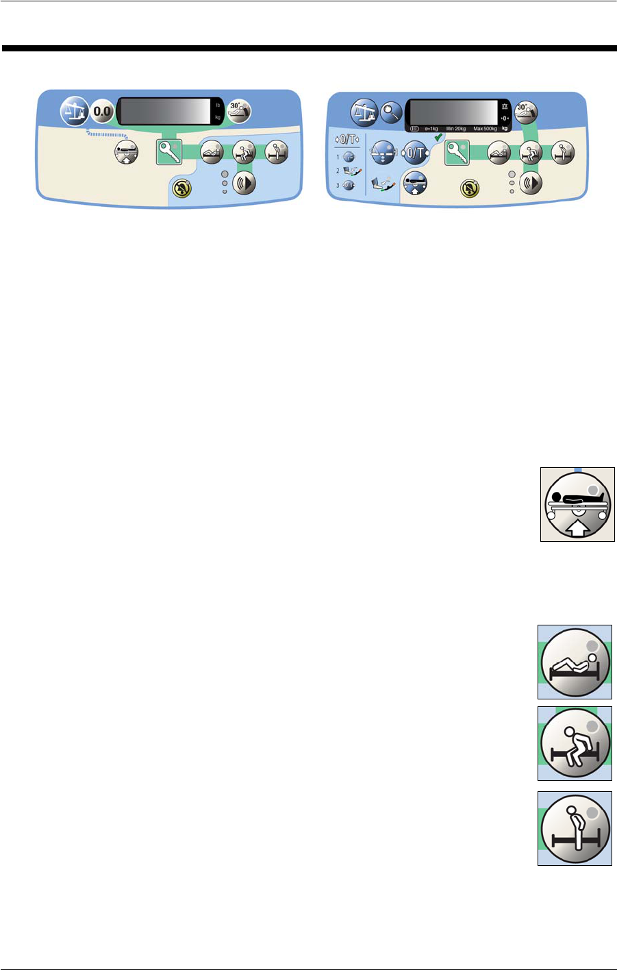
60 Compella™ Bariatric Bed System User Manual (178951 REV 1)
Three-Mode Bed Exit Alert System
THREE-MODE BED EXIT ALERT SYSTEM
NOTE:
The Bed Exit Alert System should be used in conjunction with a sound falls-risk assessment
and facility approved protocol.
The Bed Exit Alert System controls are on the flip-up control pod that is on the
intermediate siderails.
If your bed is equipped with the Compella™ Low Air Loss Surface with Turn Assist and CLRT
(Continuous Lateral Rotation Therapy), Bed Exit should be used in the Normal mode only. It
should not be used with the CLRT mode active as it may cause false alerts.
NOTE:
If the bed is in Transport Mode (the power drive wheels are on the ground)
and you attempt to arm the Bed Exit system, the Raise Bed control indicator
on the control pod will flash 5 times and you will hear a triple beep. To remove
the bed from the Transport Mode, press and hold the Raise Bed control until
its indicator turns off and you hear a single beep; the bed is ready to arm Bed
Exit.
Bed Exit has three modes: Patient Position, Bed Exiting, and Out-of-Bed.
• Patient Position Mode—this mode sounds an alert when the patient
moves towards either siderail, moves away from the head section, or
sits up in bed. This mode should be used when a caregiver wants to
be notified when the patient begins to move.
• Bed Exiting Mode—this mode sounds an alert when a patient moves
away from the center of the bed towards an egress point. This mode
should be used when a caregiver wants to be notified when a
potential egress is attempted.
• Out-of-Bed Mode—this mode sounds an alert when the patient's
weight shifts significantly off the frame of the bed. This mode should
be used when a caregiver wants the patient to move freely within the
bed, but to be notified when the patient leaves the bed.

Compella™ Bariatric Bed System User Manual (178951 REV 1) 61
Three-Mode Bed Exit Alert System
When the system is armed and it detects an alert condition for the set Bed Exit mode, the
following occur even if the patient returns to the bed:
• An audible alert comes on.
• The indicator for the applicable Bed Exit mode flashes.
• A priority nurse call is sent to the nurses station (for beds equipped with Nurse Call).
TO ACTIVATE THE BED EXIT ALERT SYSTEM
1. Make sure the patient is centered on the bed.
2. Make sure the bed is not in the Transport Mode.
3. Press the Enable key until its indicator comes on.
4. Press the desired Bed Exit mode control. When the system beeps one
time and the indicator stays on solid, the system is armed.
NOTE:
The indicator flashes until the system is armed.
If the system does not arm, the system will beep rapidly for a few seconds and the
selected mode indicator will flash. This means the patient weighs less than 113 kg (250 lb)
or more than 454 kg (1000 lb), the patient is not correctly positioned, or the system has
malfunctioned.
NOTE:
It is important to remember that the patient needs to be in the center of the bed;
otherwise, when the bed re-arms itself, the system may sound an alert.
NOTE:
If the Bed Exit mode was not deactivated before the bed was put into Transport Mode,
upon restoring power after the transport, the previously-set Bed Exit mode will re-arm.
TO SILENCE THE BED EXIT ALERT SYSTEM WITHOUT DEACTIVATING THE
SYSTEM
When a Bed Exit mode is armed, you can silence the alert system. During this Silence Mode,
the system stops monitoring the patient movement; therefore, the system does not turn
on the audible alert or send a nurse call alert. While the system is in the Silence Mode,
you can change the position of the patient or assist the patient out of the bed. Alarm
Silence can be used during Turn Assist.
• To silence the alert system before it sounds—press the Enable key
until its indicator is on solid, and then press the Alert Silence control
until its indicator is on solid.
62 Compella™ Bariatric Bed System User Manual (178951 REV 1)
Three-Mode Bed Exit Alert System
• To silence the alert system after it sounds—press the Alert Silence
control until its indicator is on solid.
Once the alert silence is activated, you have 30 seconds to either have the
patient exit the bed or return to the correct position for Bed Exit to arm.
• If the patient does not exit the bed, the patient must be returned to the correct
position for the Bed Exit mode to re-arm.
• If the patient exits the bed, the alert will not sound. The Bed Exit mode will not re-
arm until the patient returns to the bed.
• After the patient has returned to the bed, the patient must be returned to the
correct position for the Bed Exit mode to re-arm. If the patient is not in the correct
position, the system will sound an alert.
TO DEACTIVATE THE BED EXIT ALERT SYSTEM
Press the Enable key until its indicator is on solid, and then press any Bed Exit mode control
until the indicator goes off.
TO ADJUST THE ALERT VOLUME
1. The patient must be on the bed.
2. The system must be armed.
3. Press the Enable key until its indicator is on solid.
4. Press and release the Volume control until the indicator that is next
to the desired volume setting comes on.
TO CHANGE THE ALERT TONE
NOTE:
We recommend that you use the same tone on all beds of a particular unit or floor, and do
not change the tone without facility authorization.
1. Activate one of Bed Exit modes. It is recommended to use another caregiver instead of
a patient to activate the Bed Exit mode.
NOTE:
To activate a Bed Exit mode, a minimum of 113 kg (250 lb) must be on the bed.
2. Activate the alert by having the caregiver exit the bed.
3. Press and hold the Volume control.
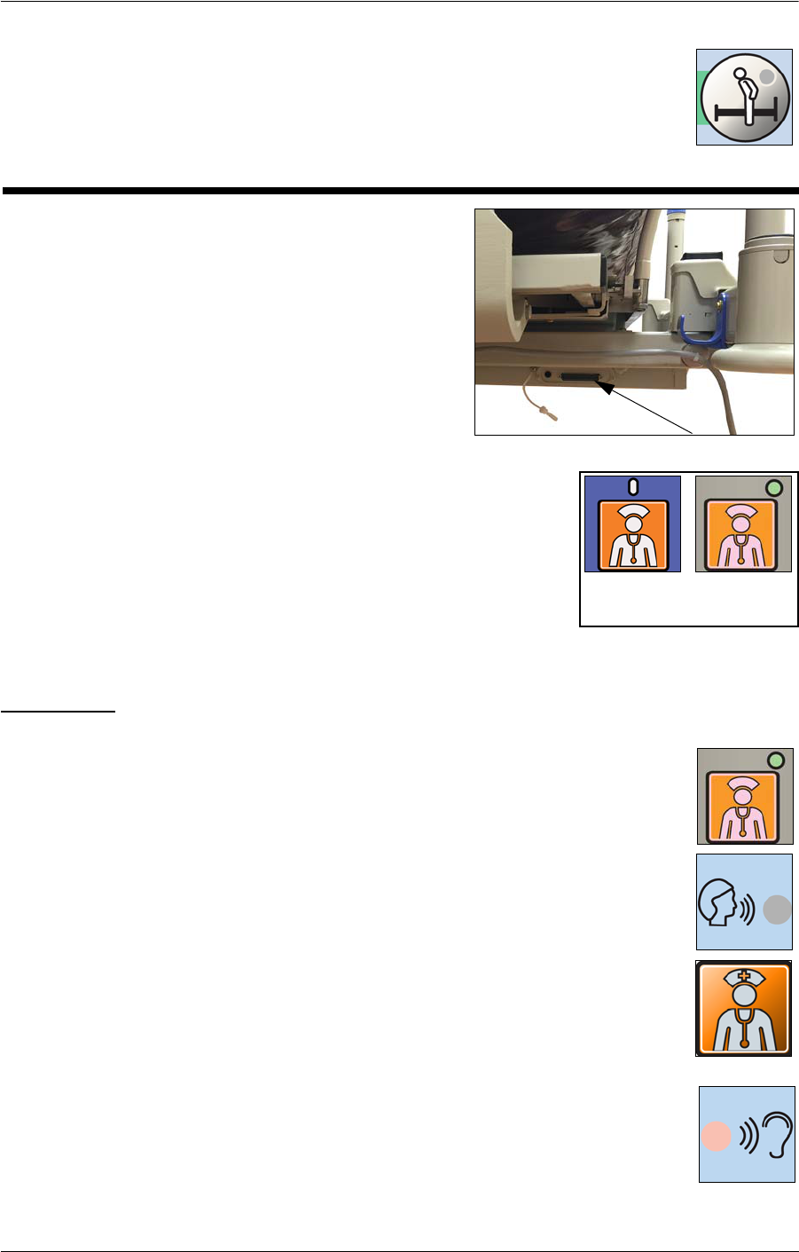
Compella™ Bariatric Bed System User Manual (178951 REV 1) 63
SideCom® Communication System
4. While you press the Volume control, press the Out-of-Bed control.
5. Press and release the Out-of-Bed control until the desired tone is reached.
6. Clear the alert condition.
SIDECOM® COMMUNICATION SYSTEM
The SideCom® Communication System provides a
control for Nurse Call.
The SideCom® Communication System connector is
on the left side of the bed at the head end.
NURSE CALL CONTROL
A Nurse Call control is on the caregiver and patient control
panels and the patient pendant (if installed).
When a Nurse Call control is activated, a signal is sent to the
nurses’ station. Voice communication is provided through a
speaker/microphone that is on the inside of both head-end siderails.
To Activate
Press a Nurse Call control. When the nurses’ station acknowledges the call,
these will occur:
• The Nurse Call indicator on the caregiver control panel will come on.
• The Voice indicator on the patient pendant will come on. The nurses’
station is ready for you to speak.
• When the call is acknowledged, the Nurse Call indicator on the patient
pendant is amber. The Nurse Call indicator on the caregiver control
panel is off.
NOTE:
If the Voice indicator or Nurse Call indicator on the patient pendant is
flashing, the Nurse Call has not yet been acknowledged.
When the Listening indicator comes on, the nurses’ station is speaking.
NOTE:
The Nurse Call controls are always active and their indicators are green when
a Nurse Call has not been initiated. The Nurse Call controls can not be locked
out.
SideCom Connector
Patient
Control
Caregiver
Control

64 Compella™ Bariatric Bed System User Manual (178951 REV 1)
Surface Features and Controls
SURFACE FEATURES AND CONTROLS
The therapy surface and air supply unit are manufactured by Tridien Medical,
and BSI is the notified body for these components of the Compella™ Bariatric
Bed System.
SAFETY INFORMATION
WARNING:
Obey all warnings and cautions throughout the manual and also the safety information
below to help prevent injury and/or equipment damage:
General
• Use of the therapy surface and air supply unit with a bed frame other than the
Compella™ Bariatric Bed could substantially reduce the effectiveness of the safety
features incorporated into the system. Patient injury could occur.
• Evaluate patients for entrapment risk according to facility protocol, and monitor
patients appropriately. Failure to do so could result in serious injury or death
• Children, pets, and pests may damage the device and may cause bodily harm to
themselves and/or the patient. Keep children, pets, and pests away from this device.
• The system is design and intended to be used with a specific Compella™ Bariatric
Bed frame. Using the air supply unit or the support surface on any other frame
could result in patient or operator injury.
Support Surface
• To avoid risk of severe injury, properly secure mattress to the frame according to the
instruction for use.
• Risk of asphyxiation due to entanglement with hoses. Make sure the hose sleeve is
correctly installed.
• Support surface handles are not intended to be used to carry patients. Using the
handles in such a manner could result in serious injury or death.
• To avoid risk of entrapment, use a correctly sized support surface for the bed frame.
• The hose sleeve is a risk mitigation, do not operate equipment without it in place.
• Make sure that all siderails are fully latched when the bed is in the raised position.
Failure to do this could result in serious injury or death including patient falls.
NOTE:
Siderails are intended to be a reminder to the patient of the unit’s edges, not a patient
restraining device.

Compella™ Bariatric Bed System User Manual (178951 REV 1) 65
Surface Features and Controls
• Smoking or improper use of radiant heaters may result in a mattress fire and injury
to the patient.
• Caregivers should be instructed to avoid punctures caused by incorrect use of x-ray
cassette holders, mobile CT, and/or needle sticks. Failure to do so could cause cross-
infection and injury.
• Examine the support surface and optional topper for damage such as punctures,
rips, or tears between patients and during cleaning cycles.
• Do not use surfaces (mattresses), mattress overlays, mattress replacements, or
specialty mattress products that have not been designed by Hill-Rom for the
Compella™ Bariatric Bed System. Use of surface products other than those designed
for the Compella™ Bariatric Bed System could substantially reduce the effectiveness
of the safety features incorporated into the system. Patient injury could occur.
Air Supply Unit
• There is a risk of asphyxiation due to entanglement with cords. Route the power
cord under the bed frame.
• There are no user serviceable parts inside. Service is to be done by facility-
authorized maintenance persons only.
• To avoid risk of electric shock use an approved power cord only.
• To avoid risk of electric shock, examine the product for damage prior to use.
• To avoid risk of burns or asphyxiation, Do not use the device in a flammable
anesthetic, O
2
, or NO
2
environment.
• AC mains power must be active to provide therapy. If power is lost, the therapy
provided will be reduced.
• To avoid risk of injury, do not place objects on the air supply unit.
• Power cord may cause tripping hazard. Route the cord under bed frame.
• Pressure in the mattress is under automated control and may adjust without notice.
Use care when performing medical procedures on a patient.
• Failure to clean the filter may result in inadequate therapy causing harm to the
patient or damage to the unit.
• To avoid unintended changes to the device settings, visitors should be made aware
that changes made to the settings may cause harm to the patient.
• Only connect the air supply unit to an approved support surface.
• To avoid the risk of electric shock, the air supply unit must only be connected to a
supply mains with protective earth.
• If the unit displays unintelligible information, stop using the device immediately
and call for service. May cause patient injury.
• During CLRT and Turn Assist, risk of a patient fall is present if the siderails are
retracted. Carefully monitor the patient when siderails are retracted.
• The power cord for the air supply unit is equipped with magnets to hold the cord in
position on the bed frame. Exposure to magnetic fields may alter the functioning of
implanted devices such as pacemakers and defibrillators.

66 Compella™ Bariatric Bed System User Manual (178951 REV 1)
Surface Features and Controls
• Do not use device in conjunction with flammable agents.
• Do not connect the power cord to an extension cord or multiple outlet strip. There
is a risk of overheating and fire may cause injury or damage.
• Only connect items that have been specified as part of the device or specified as
being compatible with the device.
• Check that the power ratings of the supply mains are sufficient to power the air
supply unit.
• Use of accessories, transducers, and cables other than those specified, with the
exception of transducers and cables sold by the manufacturer of the device as
replacement parts for internal components, may result in increased emission
and/or decreased immunity of the device.
• Observe precautions regarding EMC; install and put into service according to the
EMC information provided in the accompanying documents.
SUPPORT SURFACE OPTIONS
The bed has two support surface options:
• Compella™ Therapy Surface with Turn Assist or Turn Assist with CLRT (see
“Compella™ Therapy Surface” on page 70)—the therapy surface system consists of
the air supply unit, therapy surface, power cord, and communication cable
• Compella™ Foam Surface with inflatable side bolsters and foot section (see
“Compella™ Foam Surface with Inflatable Side Bolsters” on page 79)—the foam
surface system consists of the air supply unit, foam surface, power cord, and
communication cable
For assistance with setup, use, or maintenance of the support surface and air supply unit or
to report issues with the system, contact your facility authorized maintenance person or
Hill-Rom Technical Support.
INSTALL THE SURFACE AND AIR SUPPLY
UNIT
WARNING:
Make sure the surface is correctly connected to the
bed frame. Otherwise, patient injury could occur.
1. Raise the head end of the bed to
approximately 30°.
2. Turn the surface so that the hoses are at the
foot end of the bed.

Compella™ Bariatric Bed System User Manual (178951 REV 1) 67
Surface Features and Controls
3. Use the surface straps on the bottom of the surface to attach the surface to the
mounting slots at the head, seat, and foot sections of the bed frame. Make sure the
mounting brackets correctly attach the surface straps to the mounting slots.
4. Raise the siderails, and then gently pull on the siderails to make sure they are fully
latched in position. Make sure there are no gaps between the surface and the siderails.
CAUTION:
When you hang the air supply unit on the footboard, make sure that the mounting bracket
is installed on the footboard correctly. Otherwise, equipment damage could occur if the air
supply unit becomes dislodged.
5. Hang the air supply unit on the mounting bracket on the footboard.
CAUTION:
Make sure that the surface being connected is correctly matched to the air supply unit to
make sure that all functions operate correctly.
6. For a therapy surface, connect the
hoses from the surface to their
respective color-coded connectors on
both sides of the air supply unit:
• On the patient right-hand side of
the air supply unit, connect the red,
blue, green, white, black, and
yellow hoses.
• On the patient left-hand side of the
air supply unit, connect the white,
black, and yellow hoses.
NOTE:
The yellow hose on the left-hand side is the low airloss hose from the top cover of the
surface.
7. For a foam surface, connect the white, black, and red hoses from the surface to the
color-coded connectors on the patient right-hand side of the air supply unit.
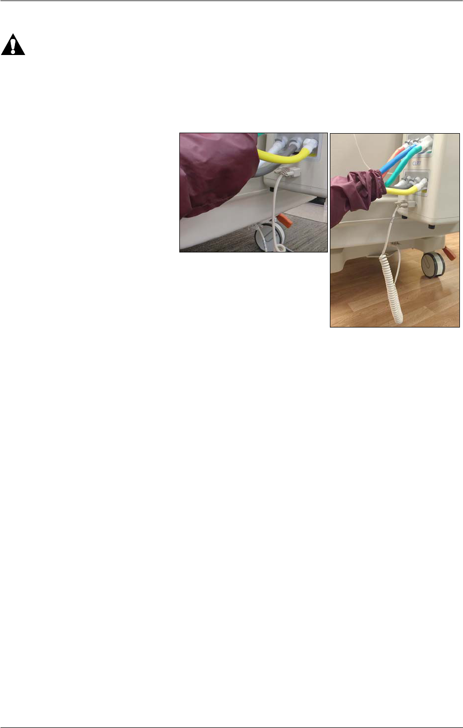
68 Compella™ Bariatric Bed System User Manual (178951 REV 1)
Surface Features and Controls
WARNING:
Incorrect use or handling of the power cord may cause damage to the power cord. If
damage has occurred to the power cord, immediately remove the bed from service, and
contact your facility-authorized maintenance person or Hill-Rom Technical Support. Failure
to do so could cause injury or damage.
8. At the foot end of the bed,
connect the surface
communication cable to the
air supply unit and to the
bed.
9. Connect the power cord to the patient left-hand side of the air supply unit.
10. Use the magnets to attach the power cord to these locations along the bed and to a
correctly grounded AC power outlet:
• Under the patient left-foot corner of the bed.
• Along the side of the intermediate frame on the patient left-hand side of the bed.
• At the patient head-left corner of the bed.
11. Plug the air supply unit power cord into the AC power outlet. Do not put the air supply
unit in a position that makes it difficult to unplug the power cord.
NOTE:
The Power switch on the caregiver’s right-side of the air supply unit turns the unit On and
Off.
12. At the same time, press and hold the Help (?) control and the Power switch. Listen for a
notification tone to make sure the audio alarm system is operating correctly. If you do
not hear a tone, do not use the air supply unit.

Compella™ Bariatric Bed System User Manual (178951 REV 1) 69
Surface Features and Controls
13. The Select Attached Mattress Model
screen shows. Select the correct surface.
14. For an air surface, set up the unit for the
patient (see page 70).
AIR SUPPLY UNIT
For air surfaces, the air supply unit shows a real-time display of air pressure for the head,
seat, and foot sections of the surface assembly.
For a Compella™ Therapy Surface, the amount of pressure to support a patient is based
on the patient’s height and weight that is entered during setup. This provides custom
weight-based pressure redistribution. All settings are stored in non-volatile memory. If
power is interrupted, the air supply unit automatically returns to the previous settings
when the power returns.
The air supply unit has these controls:
• Menu—selects the Menu options.
• Enter—moves to and from the Patient Setup screen.
• Help—shows the Help screen.
• Arrows—selects settings on the Patient Setup screen.
Without CLRT
With CLRT
Menu
Enter Help
Arrows

70 Compella™ Bariatric Bed System User Manual (178951 REV 1)
Surface Features and Controls
COMPELLA™ THERAPY SURFACE
The Compella™ Therapy Surface is a therapeutic system that supplies three zone, constant
pressure redistribution, microclimate management, Turn Assist and Continuous Lateral
Rotation Therapy (CLRT). The Compella™ Bariatric Therapy Surface consists of either:
• Therapy Surface with Turn Assist
• Therapy Surface with Turn Assist and CLRT
The Compella™ Therapy Surface supports a patient weight up to 454 kg (1000 lb). The air
supply unit has a maximum weight input of 455 kg or 995 lb.
NOTE:
The weight is entered in 5 kg or 5 lb increments.
Set Up the Unit for the Patient
1. At the Pressure Redistribution screen,
press the Enter control on the air supply
unit. The Patient Setup screen shows.
2. Enter the patient’s height and weight as
follows:
a. Use the arrow keys on the right-side
of the display to select Height or
Weight.
b. Enter the patient’s height and weight as follows:
• To increase the shown height or weight, press Increase.
• To decrease the shown height or weight, press Decrease.
3. The unit automatically adjusts the pressures for the set height and weight. If necessary,
use the arrow keys to move the cursor to the applicable pressure setting: head, seat, or
foot, and adjust the settings as follows:
•To increase the pressure, press Increase.
•To decrease the pressure, press Decrease.
•To return all pressure settings to the pressures automatically set by the unit for the
set height and weight, press Default.
NOTE:
To make sure that the patient is getting the proper therapy, periodically check that the
support surface is properly inflated for patient support.
4. Press Enter to save the pressure settings and return to the Pressure Redistribution
screen.

Compella™ Bariatric Bed System User Manual (178951 REV 1) 71
Surface Features and Controls
NOTE:
If you do not press Enter, the settings will not be saved.
Surface Options
Max Inflate Mode
Max Inflate mode inflates the surface assembly to its maximum pressures.
NOTE:
The surface goes into Hyper-Inflate mode to inflate the surface after Seat Deflate and Bed
Deflate modes; it does not go into Max Inflate mode.
To turn Max Inflate mode on, do as follows:
1. At the Pressure Redistribution screen,
press Max Inflate:
The Max Inflate (65 mm Hg) screen
shows the 30-minute countdown.
2. To turn Max Inflate mode off when it has
been on for less than 30 minutes, press
Max Inflate again.
If the unit is in Max Inflate mode for 29
minutes, the alarm sounds, and the 1-minute
countdown screen shows:
•Press Max Inflate Off to stop Max
inflate mode.
•Press Continue Max Inflate to continue Max Inflate mode for 10 minutes.
• Do nothing—Max Inflate mode ends at the end of the 1-minute countdown and
the surface returns to the previous mode.
If the 10-minute extension is selected, then a
10-minute counter screen shows:
• Press the highlighted Max Inflate
option to stop Max inflate mode
immediately.
• Select any of the other options.
Fowler Boost Mode
When the unit is turned on, it automatically defaults to Fowler Boost
mode. For patients in an inclined position, Fowler Boost mode increases
support in the seat zone.
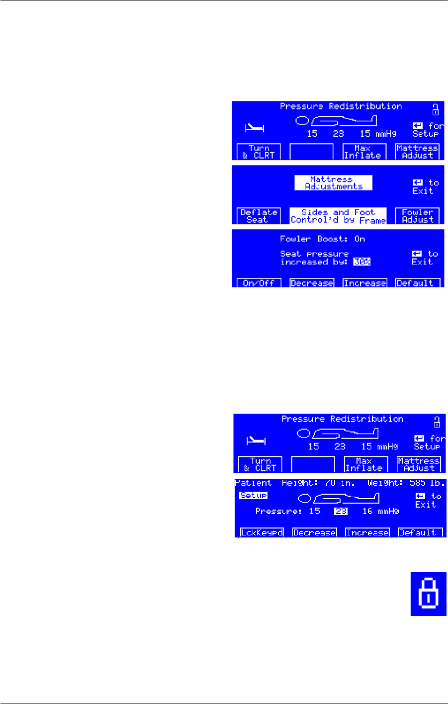
72 Compella™ Bariatric Bed System User Manual (178951 REV 1)
Surface Features and Controls
NOTE:
When the unit is in Fowler Boost mode, the Fowler Boost indicator is on.
To turn Fowler Boost mode on or off, do as follows:
1. At the Pressure Redistribution screen,
press Mattress Adjust. The Mattress
Adjustments screen shows.
2. Press Fowler Adjust. The Fowler Boost
screen shows.
3. Press On/Off to turn Fowler Boost mode
On or Off.
4. If necessary, adjust the setting as follows:
• To increase the pressure, press
Increase.
• To decrease the pressure, press
Decrease.
•Press Default to return to the standard Fowler Boost setting of 30% more than the
seat section’s set pressure.
5. Press Enter to return to the previous therapy screen.
Lock or Unlock the Control Panel
1. At the Pressure Redistribution screen,
press Enter. The Patient Setup screen
shows.
2. Press Lck Keypd. The control panel’s
lockout status changes, and the previous
therapy screen shows.
NOTE:
When the control panel is locked, the Lockout indicator shows in the upper right-
hand corner of the screen.
Turn Assist Mode
Turn Assist mode helps the caregiver to turn the patient to the left or the right.
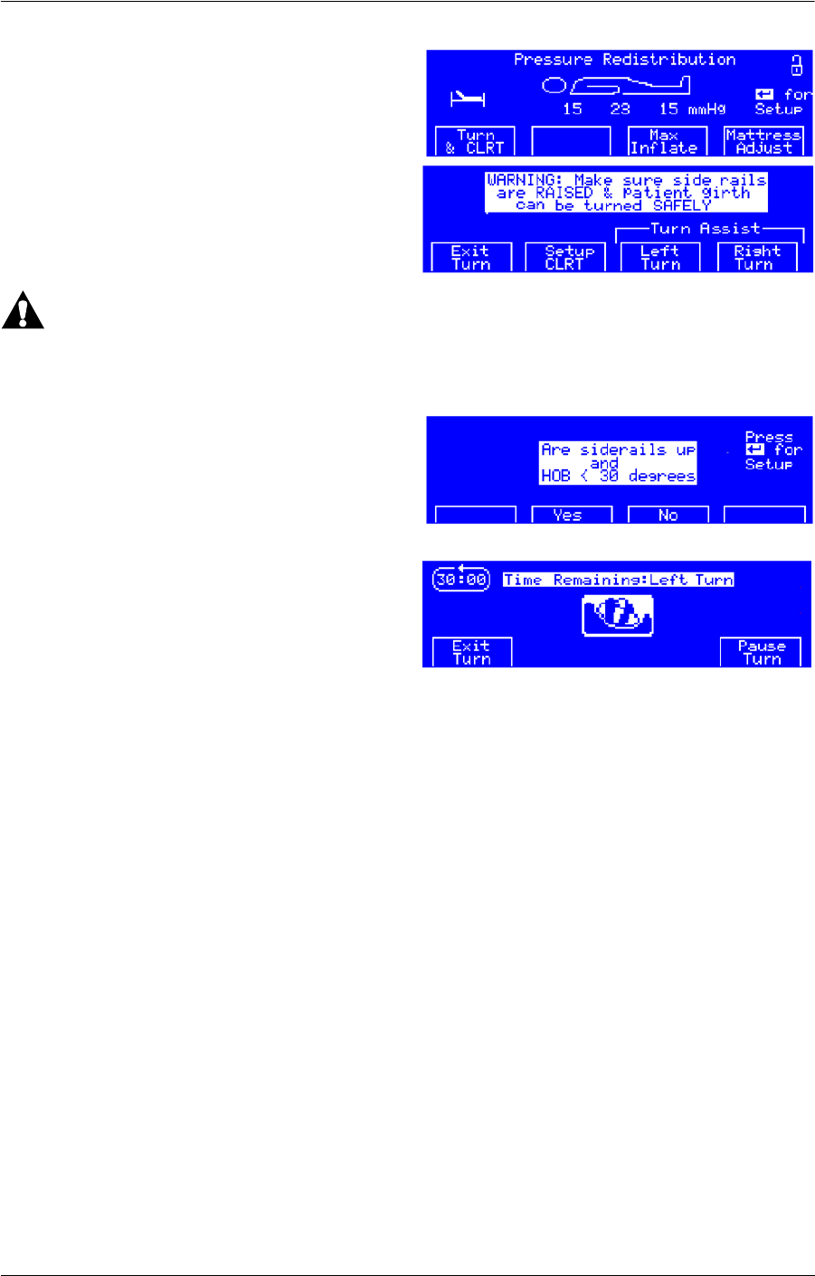
Compella™ Bariatric Bed System User Manual (178951 REV 1) 73
Surface Features and Controls
To start the Turn Assist mode, do as follows:
1. At the Pressure Redistribution screen,
press Turn & CLRT.
2. The next screen shows the Turn Assist
Left Turn, Right Turn or Exit Turn
options. Select one.
WARNING:
Do not start a turn in either of these instances: the head section (HOB) angle is greater than
30°; the siderails are not in the Up position. To do so could cause patient injury.
3. At the Turn Assist Warning screen, make
sure the siderails are in the up position
and the head section is less than 30°.
4. Press Ye s .
5. The selected turn starts and a 30-minute
countdown screen shows with two menu
options:
•Pause Turn—this option stops the
turn at the current angle. Pause will
then change to Resume, which permits the turn to continue until completion, as
indicated by one long beep.
• Exit Turn—this option brings the patient back to a flat position.
NOTE:
If you retract or extend the bed width during the Turn Assist mode, the Pause function will
activate to permit the bolsters to deflate or inflate, then the Turn Assist mode will resume.
6. 1 minute before the Turn mode times out, an audible alarm sounds with menu options
to Exit the turn and thus return the patient to a flat position, or Extend the turn for
another 30 minutes.
7. When the 30 minutes lapse, the patient returns to the flat position and the display goes
back to the Main screen.

74 Compella™ Bariatric Bed System User Manual (178951 REV 1)
Surface Features and Controls
Deflate and Inflate the Seat Section for Patient Exit or Entry
1. At the Pressure Redistribution screen,
press Mattress Adjust.
2. At the Mattress Adjust screen, press
Deflate Seat. The Do you want to
deflate seat section? screen shows.
3. Press Ye s . The seat section fully deflates
within 4 minutes as shown on the Seat
Deflating countdown screen.
4. If the seat section is deflated for 30
minutes, the alarm sounds. To continue
with the Deflate Seat mode, press Audio
Pause to mute the alarm for 10 minutes.
To inflate the seat section and exit the
Deflate Seat mode, do as follows:
1. Press Inflate and Exit. The Surface
Inflating screen flashes for 10 seconds.
2. The unit goes into Hyper-Inflate mode to inflate the surface to 55 mm Hg for 10
minutes:
If the unit is in Pressure Distribution
mode, the Hyper-Inflate screen shows
and highlights Hyper Inflate.
Continuous Lateral Rotation Therapy (CLRT) Mode
The rotation mode provides gentle, side-to-side, continuous lateral rotation therapy (CLRT)
to help prevent and treat pulmonary complications related to immobility. Patients can be
positioned laterally on the right or left side with varying amounts of turn and pause times
to match each individual patient’s condition. Pressure relief is provided when the rotation
mode is active.

Compella™ Bariatric Bed System User Manual (178951 REV 1) 75
Surface Features and Controls
To start CLRT mode, do as follows:
1. At the Pressure Redistribution screen,
press Turn & CLRT.
2. Make sure the siderails are raised. Press
Setup CLRT.
3. At the Setup CLRT screen, use the
Decrease and Increase buttons to
increase or decrease the highlighted %
of turn (10% increments) or hold times
(30-second increments).
NOTE:
Use the arrow keys on the right side of the control panel (inside the diamond) to highlight
what you need to adjust.
4. After the parameters are set, press the Enter key to continue.
WARNING:
Do not start a turn in either of these instances: the head section (HOB) angle is greater than
30°; the siderails are not in the Up position. To do so could cause patient injury.
5. At the Siderail warning screen, press Ye s
or No.
6. The CLRT Mode screen shows.
7. CLRT begins. During therapy you have
the option to Exit CLRT, Pause, or Max
Inflate
.
NOTE:
If you retract or extend the bed width during
CLRT, the Pause function will activate to permit the bolsters to deflate or inflate.
Menu Enter Help
Arrows

76 Compella™ Bariatric Bed System User Manual (178951 REV 1)
Surface Features and Controls
8. If Pause is selected, the patient will stop
rotating and stay at the current angle for
10 minutes and then resume. From
Pause you can Exit CLRT and return to
the Pressure Redistribution screen or
Resume CLRT.
9. If Max Inflate is selected, the patient is
centered and cushions inflated to
maximum pressure. From there you can
Exit CLRT and return to the main screen
or you can Resume CLRT.
10. If Exit CLRT is selected, the patient is centered, CLRT stops and the surface goes into
pressure redistribution mode. The main screen appears.
Deflate and Inflate the Side Bolsters and Foot Section
Automatically (using the Caregiver Width Adjust controls)
The side bolsters and foot section automatically adjust to the frame
width and/or length as long as the bed is plugged into AC power and
the air supply unit is correctly connected to the frame (see “Bed
Width Adjustment” on page 39).
Side Bolsters
• The side bolsters will inflate anytime the
frame width extensions are all fully
extended.
• The side bolsters will deflate for 2
minutes anytime some or all of the frame
width extensions are partially or fully
retracted.
Foot Section
The foot section will automatically inflate or deflate sufficiently to accommodate any
adjustment to the foot extension of the frame.
Manually (using the Air Supply Unit)
The side bolsters and foot section can be operated manually only when the frame is
disconnected from AC power or the air supply unit loses communication with the frame.
Retract
Extend

Compella™ Bariatric Bed System User Manual (178951 REV 1) 77
Surface Features and Controls
Side Bolsters
To deflate the side bolsters, do as follows:
1. At the Pressure Redistribution screen,
press Mattress Adjust.
2. Press Deflate Sides. The Sides Deflating
screen shows.
NOTE:
During the Deflate Sides mode, you may use
Seat Deflate mode, Foot Deflate mode, Max
Inflate mode, or Transport Deflate mode as
necessary.
3. If the side bolsters are deflated for 30
minutes, an alarm sounds, and the
Warning: Sides Deflated screen shows:
• To mute the alarm for 10 minutes,
press Extend Deflate.
• The Side Deflate, 10-minute
countdown screen shows.
To inflate the side bolsters, do as follows:
1. At the Side Deflate screen, press
Mattress Adjust. The Mattress
Adjustments screen shows.
2. Press Inflate Sides. The side bolsters
inflate, and the unit goes into Pressure
Redistribution mode in 10 seconds.
Foot Section
To deflate the foot section, do as follows:
1. At the Pressure Redistribution screen,
press Mattress Adjust. The Mattress
Adjustments screen shows.

78 Compella™ Bariatric Bed System User Manual (178951 REV 1)
Surface Features and Controls
2. Press Deflate Foot. The foot section
deflates, the Foot Deflating screen
shows for 2 minutes, and then the main
therapy screen shows.
To cancel Foot Deflate prior to completion
press Inflate and Exit. The foot section
inflates, the Foot Inflating screen flashes for
10 seconds, and then the main therapy
screen shows.
After the foot section has been deflated, the
Deflated Foot indicator shows on the main
therapy screen. To inflate the foot section, do
as follows:
1. Press Mattress Adjust. The Mattress
Adjustments screen shows.
2. Press Inflate Foot. The foot section
inflates, the Foot Inflating screen flashes
for 10 seconds, and then the main
therapy screen shows.
Deflate the Side Bolsters and Foot Section for Patient Transport
To deflate the side bolsters and foot section for patient transport, do as follows:
1. At the Pressure Redistribution screen,
press Patient Transpt. The Do you want
to deflate for transport? screen shows.
2. Press Ye s . The side bolsters and foot
section of the surface start to deflate, and
the Deflating for Transport screen
shows.
NOTE:
If you press No, the display returns to the main therapy screen.

Compella™ Bariatric Bed System User Manual (178951 REV 1) 79
Surface Features and Controls
3. When the side bolsters and foot section
are deflated, the Ready for Transport
screen shows.
4. If the surface is deflated for more than 30
minutes, the alarm sounds. To mute the
alarm for 10 minutes, press Audio Pause.
To inflate the side bolsters and foot section,
press Inflate and Exit. The Surface Inflating
screen flashes, the side bolsters and foot
section inflate, and the unit goes into
Pressure Distribution mode in 10 seconds.
COMPELLA™ FOAM SURFACE WITH INFLATABLE SIDE BOLSTERS
The foam surface with inflatable side bolsters
and foot section is for patient weights up to
454 kg (1000 lb). The width of the foam
surface is adjustable from 40" to 50" (102 cm
to 127 cm).
Deflate and Inflate the Side Bolsters and Foot Section
Automatically (using the Caregiver Width Adjust controls)
The side bolsters and foot section automatically adjust to the frame
width and/or length as long as the bed is plugged into AC power and
the air supply unit is correctly connected to the frame (see “Bed
Width Adjustment” on page 39).
Side Bolsters
• The side bolsters will inflate any time the
frame width extensions are all fully
extended.
• The side bolsters will deflate for 2
minutes any time some or all of the frame
width extensions are partially or fully
retracted.
Manually (using the Air Supply Unit)
The side bolsters and foot section can be operated manually only when the frame is
disconnected from AC power or the air supply unit loses communication with the frame.
Retract
Extend
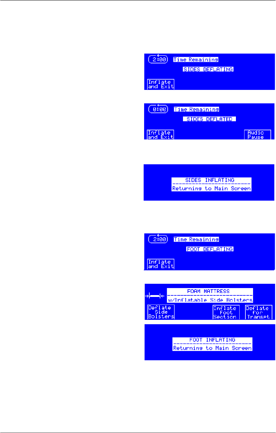
80 Compella™ Bariatric Bed System User Manual (178951 REV 1)
Surface Features and Controls
Side Bolsters
To deflate the side bolsters, do as follows:
1. At the Foam Mattress screen, press
Deflate Side Bolsters. The Sides
Deflating screen shows, a 2-minute
countdown starts, and the side bolsters
deflate.
2. If the side bolsters remain deflated for 30
minutes, an alarm sounds. To mute the
alarm for 10 minutes, press Audio Pause.
To inflate the side bolsters on the foam surface, do as follows:
At the Deflate Sides screen, press Inflate
and Exit. The Sides Inflating screen
shows, the side bolsters inflate, and then
the Foam Mattress screen shows.
Foot Section
To deflate the foot section of the surface, do as follows:
At the Foam Mattress screen, press
Deflate Foot Section. The foot section
deflates, and the Foot Deflating screen
shows for 2 minutes.
NOTE:
After 2 minutes of Deflate Foot mode, the
Foam Mattress screen shows.
To inflate the foot section, do as follows:
If the Deflate Foot mode has been on for
less than 2 minutes, press Inflate and
Exit at the Foot Deflating screen.
or
If the Deflate Foot mode has been on for
more than 2 minutes, press Inflate Foot
Section at the Foam Mattress screen.
The Foot Inflating screen shows, the foot section inflates, and then the Foam Mattress
screen shows.

Compella™ Bariatric Bed System User Manual (178951 REV 1) 81
Surface Features and Controls
Deflate and Inflate the Side Bolsters and Foot Section for Patient
Transport
To deflate the side bolsters and foot section for patient transport, do as follows:
1. At the Foam Mattress screen, press
Deflate for Transpt. The Do you want to
deflate for transport? screen shows.
2. Press Ye s . The side bolsters and foot
section of the surface start to deflate, and
the Deflating for Transport screen
shows.
NOTE:
If you press No, the display shows the Foam
Mattress screen.
3. When the side bolsters and foot section
are deflated, the Ready for Transport
screen shows.
4. If the surface is deflated for more than 30
minutes, the alarm sounds. To mute the
alarm for 10 minutes, press Audio Pause.
To inflate the side bolsters and foot section,
do as follows:
Press Inflate and Exit. The Surface
Inflating screen flashes, the side bolsters
and foot section inflate.
Air Supply Unit—Informational Tones
The unit generates informational tones to let the caregiver know the system status during
its operation. This includes single beeps that let the caregiver know these:
• Input is necessary to change the functionality of the system.
• A full turn has been completed.
• Communications with the bed frame has been lost.

82 Compella™ Bariatric Bed System User Manual (178951 REV 1)
Accessories
ACCESSORIES
WARNING:
Zero the scale before a new patient is put on the bed and whenever additional equipment
is added to the bed. Failure to do so could cause an inaccurate weight reading; patient
injury could occur.
After you install an accessory on the bed, zero the scale. See “Scale Systems” on page 51.
Part Number Description
Accessories for North America
P2217A IV Pole
P27601 Oxygen tank holder, vertical
P7802A Patient Helper
P7803A01 Pendant
P7803A02 Pendant, with Nurse Call
P3670A01 Respiratory circuit holder
P3670A05 Pressure transducer holder
P158A
a
a. Adapter bracket P163 must be installed for use of P158A.
Infusion Support System (ISS)
P163 ISS socket adapter
P7801A01 Headboard, capital
P7512A Line Managers
Accessories for International
71438 Adapter, IV pole
AC959A Oxygen tank holder 150 mm
AD101A Oxygen tank holder 110 mm (D size)
AD102A Oxygen tank holder 110 mm (E size)
AC962A Pivoting 3-liter cylinder holder
AD148A Telescopic IV pole
AD165A Telescopic IV pole
AC963A Syringe-driver holder

Compella™ Bariatric Bed System User Manual (178951 REV 1) 83
Accessories
ACCESSORIES FOR NORTH AMERICA
IV Pole (P2217A)
WARNING:
To help prevent personal injury or equipment
damage, follow these warnings and cautions:
• Do not exceed the 11 kg (25 lb) load
capacity of the IV pole.
• Correctly attach the IV pole; otherwise, it
may fall.
• Uneven loading of the IV pole could cause the contents to fall.
• When you lower the upper section of an IV pole, always hold the upper section of
the pole before you pull the release knob.
• Install the IV pole in an equipment socket only. See “Equipment Sockets” on page
37.
The IV pole is a removable, telescopic pole that installs in any of the equipment sockets.
To Install
Insert the IV pole vertically into any of the equipment sockets at either the head end or foot
end of the bed.
To Remove
Pull the IV pole out from the equipment socket.
Oxygen Tank Holder, Vertical (P27601)
WARNING:
Failure to correctly attach the oxygen tank holder could cause it to drop. Injury or
equipment damage could occur.
The oxygen tank holder holds one E size oxygen tank with a regulator. The mount location
lets the affixed oxygen tank holder pivot. The safe working load of the oxygen tank holder
is 14 kg (30 lb).
To Install
1. Install the mounting bar vertically into any of the equipment sockets at either the head
end or foot end of the bed.
2. Put the oxygen tank in the oxygen tank holder.
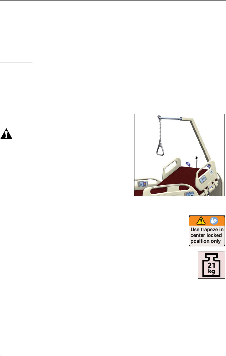
84 Compella™ Bariatric Bed System User Manual (178951 REV 1)
Accessories
3. Tighten the holder thumbscrew to keep the oxygen tank in position.
NOTE:
Make sure that when you put an oxygen tank in the holder that the tank does not interfere
with the head section articulation.
To Remove
1. Loosen the thumbscrew that holds the oxygen tank tight in the oxygen tank holder.
2. Lift the oxygen tank out of the oxygen tank holder.
3. Lift up on the oxygen tank holder, and remove it from the equipment sockets.
Patient Helper (P7802A)
WARNING:
To help prevent personal injury or equipment
damage, follow these warnings and cautions:
• Do not exceed the 227 kg (500 lb) load
capacity of the Patient Helper arm assembly.
• Correctly attach the Patient Helper arm
assembly; otherwise, it may fall.
• Do not remove or install the Patient Helper
arm assembly while it is in a position over a
patient.
• For use, the Patient Helper trapeze must be locked in the center
position.
• The complete Patient Helper weighs 21 kg (46.3 lb). Use correct
lifting techniques and/or ask for assistance when you install or remove
the Patient Helper.
The Patient Helper can be used to help assist patients with mobility. It can be
rotated to either the left or right for better access to the patient during
nursing care, or for positioning an X-Ray machine over the patient.
To rotate the arm, pull the T-handle that is on the Patient Helper mount while you turn the
arm assembly to the left or right.

Compella™ Bariatric Bed System User Manual (178951 REV 1) 85
Accessories
To Install
1. Remove the cover from the Patient Helper mount on the bed. Keep
the cover.
2. Turn the arm assembly so that it is towards the left or right side of the
bed, and install the arm assembly into the Patient Helper mount.
3. Pull the T-handle that is on the Patient Helper mount until the arm
assembly lowers into position.
4. Install the horizontal arm into the arm assembly, and insert the pull
pin to hold the horizontal arm in position.
5. Install the clamp of the trapeze handle assembly on to the horizontal
arm, and tighten the clamp to attach the trapeze handle assembly to
the horizontal arm.
6. Turn the arm weldment so the trapeze handle is centered over the
bed and the T-handle locks into position.
To Remove
1. Pull the T-handle that is on the Patient Helper mount, and turn the
arm assembly so that the trapeze handle is over the side of the bed.
2. Loosen the clamp that attaches the trapeze handle assembly to the
horizontal arm, and remove the trapeze handle assembly from the
horizontal arm.
3. Remove the pull pin and horizontal arm from the arm assembly.
4. Remove the arm assembly from the Patient Helper mount.
5. Install the cover on to the Patient Helper mount.
Patient Pendant (P7803A01/02)
To Install
1. Put the pendant into position in the opening
from the patient side of a head-end siderail.
2. Set the top edge of the pendant into the siderail
so it engages the upper section of the siderail.
3. Rotate the lower edge of the pendant inward
until it clicks into position inside the siderail.

86 Compella™ Bariatric Bed System User Manual (178951 REV 1)
Accessories
When the pendant is not in use, we recommend that you keep it stored in its slot in the
siderail.
To Remove
Gently pull the pendant out from the siderail.
Pressure Transducer Holder
(P3670A05) and Respiratory Circuit
Holder (P3670A01)
WARNING:
To help prevent personal injury or equipment
damage, follow these warnings and cautions:
• After you raise or lower the head section,
make sure the holder is in the correct
position.
• When the holder is installed, use caution when you move around the bed, move the
bed, or transfer a patient in or out of the bed.
• Use the holder for medical equipment only.
• During rotation, monitor the patient rotation angle and make sure that the patient
stays centered on the surface with shoulders correctly aligned, and that there is
sufficient slack in lines for patient movement and surface rotation.
• Do not attach height sensitive devices or transducers with drainage capacity.
• Do not exceed the 2.2 lb (1 kg) load capacity of each holder.
• Do not use a holder to move the bed.
The pressure transducer holder and respiratory circuit holder are used to hold respiratory
ventilator circuits and pressure transducers and keep them in position. The P3670A01 is the
tube holder configuration, and the P3670A05 is the transducer configuration. The holders
can be mounted on either or both corners of the head section. Refer to the manufacturer’s
instructions for operation.
To Install
1. Loosen the knob on the bottom of the holder bracket.
2. Slide the holder bracket on to the bed mount bracket until it stops.
3. Tighten the knob.
4. Put the holder in the applicable position.

Compella™ Bariatric Bed System User Manual (178951 REV 1) 87
Accessories
Infusion Support System (P158A)
WARNING:
To help prevent personal injury or equipment damage, follow these
warnings and cautions:
• Do not exceed the 9 kg (20 lb) load capacity of the infusion
support system (ISS) pole.
• When you lower the upper section of an ISS pole, always hold
the upper section of the pole before you pull the release knob.
NOTE:
Make sure when you mount infusion pumps on an IV pole that they do
not interfere with the head section articulation.
The ISS consists of a movable and adjustable IV pole. The pole
supports IV pumps or bags in a vertical orientation and raises or lowers the pumps or bags
with respect to the system frame.
The head end of the system has attaching points for two mobile ISS poles. Each pole can
support one infusion pump plus two liters of intravenous solution.
Before you install the ISS pole (P158A), it is necessary to install the P163 ISS socket adapter.
Headboard (P7801A01)
The headboard is available with or without a user
manual holder.
The headboard attaches to the head end of the
frame.
The headboard can be removed for increased access
to the patient’s head.
A caregiver can quickly remove or attach the
headboard in a single step without the use of tools.
To Remove
Lift the headboard straight up.
To install
Align the headboard pins with the sockets in the frame and then lower the headboard into
the sockets. Push the headboard down until the bottom rests on the frame.

88 Compella™ Bariatric Bed System User Manual (178951 REV 1)
Accessories
Line Managers (P7512A)
WARNING:
To help prevent personal injury or
equipment damage, follow these warnings
and cautions:
•Do not use the line managers to
secure ventilator tubing; use only
approved ventilator tubing devices.
•Do not wrap power cords around the line managers.
The line managers help keep lines such as IVs, suction tubing, and monitor cables together
and away from the articulation of the frame.
ACCESSORIES FOR INTERNATIONAL
IV Pole Adapter (71438)
The IV pole adapter needs to be removed from the equipment
sockets so that the International accessories fit into the
sockets.
Oxygen Tank Holders (AC959A, AD101A, and AD102A)
WARNING:
Do not exceed the load capacity of the oxygen tank holders; refer to the value shown on
the holder. To do so could cause personal injury or equipment damage.
The oxygen tank holders are designed to hold an oxygen tank. Each holder is designed to
hold a specific-sized oxygen tank and must never be used with a different size oxygen tank.

Compella™ Bariatric Bed System User Manual (178951 REV 1) 89
Accessories
When you use one of the oxygen tank holders, follow these recommendations:
• Make sure that the oxygen tank holder is correctly inserted into one of the
equipment sockets at any of the four corners of the bed.
• Make sure that the oxygen tank is correctly inserted in the holder.
• Do not use a different oxygen tank model from the model specified. The tank could
fall or interfere with other operations.
• Make sure that the holder is in a safe position before you adjust the tilt of the bed or
lower the bed.
• If the holder does not permit the bed to pass through a doorway, adjust the holder
so that it is at the front of the bed or put the holder and cylinder on the bed
(remember to return the holder to its normal location after the transport).
Pivoting 3-Liter Cylinder holder (AC962A)
We recommend that you install the cylinder holder at the foot end of the bed.
WARNING:
Do not exceed the load capacity of the cylinder holder; refer to the value shown on the
holder. To do so could cause personal injury or equipment damage.
When you use the cylinder holder, follow these recommendations:
• Make sure that the holder is correctly inserted in either equipment socket at the
foot end of the bed.
• Make sure that the 3-liter cylinder is correctly inserted in the holder.
• Do not use a different sized cylinder from the size specified. The cylinder could fall
or interfere with other operations.
• Make sure that the holder is in a safe position before you adjust the tilt of the bed or
lower the bed.
• If the holder does not permit the bed to pass through a doorway, adjust the holder
so that it is at the foot of the bed or put the holder and cylinder on the bed
(remember to return the holder to its normal location after the transport).
Telescopic IV Poles (AD165A and AD148A)
WARNING:
To help prevent personal injury or equipment damage, follow these warnings and
cautions:
• Do not exceed the load capacity of the IV poles; refer to the value shown on the IV
pole.
• Make sure the IV pole is installed so that it is toward the bed and not outward.

90 Compella™ Bariatric Bed System User Manual (178951 REV 1)
Accessories
To Use the IV Pole with Four Hooks (AD165A)
1. Insert the IV pole vertically into any of the equipment sockets at either the head end or
foot end of the bed.
2. To adjust the height of the pole, do these:
a. Loosen the knob on the pole as you hold the lower section of the pole.
b. Hold the upper section of the pole, just below the plastic sleeve.
c. Push the sleeve upwards, and adjust the pole to applicable height.
d. Tighten the knob.
3. To adjust the angle of the pole, do these:
a. Loosen the knob on the pole as you hold the lower section of the pole.
b. Adjust the upper section of the pole to the applicable angle. Make sure that the
pole is in a safe position.
c. Tighten the knob.
To Use the IV Pole with Two Hooks (AD148A)
1. Insert the IV pole vertically into any of the equipment sockets at either the head end or
foot end of the bed.
2. To adjust the height or angle of the pole, do these:
a. Loosen the knob on the pole as you hold the upper section of the pole.
b. As you hold the lower section of the pole, adjust the pole to the applicable height
or angle. Make sure that the pole is in a safe position.
c. Tighten the knob.
Syringe-Driver Holder (AC963A)
WARNING:
To help prevent personal injury or equipment damage, follow these warnings and
cautions:
• Do not exceed the load capacity of the syringe-driver holder; refer to the value
shown on the holder.
• Do not install the holder so that it is towards the bed. To do so could cause
interference with the bed and siderail articulations.
The holder is designed to hold syringe-drivers and is to be installed in the equipment
sockets on either side of the head end of the bed.

Compella™ Bariatric Bed System User Manual (178951 REV 1) 91
Cleaning/disinfecting
To Adjust the Holder Position
1. Hold the table as you loosen the knob.
2. Adjust the table as applicable, and then tighten the knob.
CLEANING/DISINFECTING
WARNING:
When you clean and disinfect the bed, air supply unit, and support surface, follow these
safety instructions; otherwise, personal injury or equipment damage could occur:
• Hill-Rom recommends that you clean and disinfect the bed, air supply unit, and
support surface between patient use and when servicing.
• The potential for electrical shock exists with electrical equipment. Failure to follow
facility protocol could cause death or serious injury.
• Always follow the cleaning product manufacturer’s instructions.
• Do not steam clean or power wash the bed, air supply unit, or support surface.
Pressure and excessive moisture can damage the protective surfaces and electrical
components.
• Do not autoclave the air supply unit or the hose assembly.
• Do not use harsh cleansers/detergents, heavy duty grease removers, solvents such
as toluene, xylene, or acetone, and do not use scouring pads (you may use a soft
bristle brush).
•Do not use high temperatures to dry the topper. Air dry or select a low or non-heat
dry cycle such as air fluff. High temperatures could impact the impermeability of
the topper.
•Do not spray disinfectant directly on the air supply unit, or immerse the air supply
unit in any type of liquid.
• Do not put the support surface on the bed until the surface and bed are completely
dry.
• Keep the air filters clean. See “Clean the Air Supply Unit Filters” on page 95.
SUPPORT SURFACE COMPONENT IDENTIFICATION
Term Description
Topper Advanced MicroClimate® Technology or low airloss surfaces
(mattresses) have a topper. The topper zips on to the top of the
surface above the cover. The topper is wipeable and machine
washable.

92 Compella™ Bariatric Bed System User Manual (178951 REV 1)
Cleaning/disinfecting
RECOMMENDATIONS
Hill-Rom recommends cleaning and disinfecting the bed, air supply unit, and support
surface between patient use and regularly during extended patient stays. Refer to your
facility’s cleaning and disinfection policies, as well as the recommendations below.
• Wipe up fluid spills as soon as possible. Always unplug the unit from its power
sources before you clean up major fluid spills. Some fluids used in the hospital
environment, such as iodophor and zinc oxide creams, can cause permanent stains.
Remove temporary stains by wiping vigorously with a lightly-dampened sponge or
cloth.
• Use an EPA registered hospital-grade disinfectant and a soft bristle brush to remove
difficult spots or stains.
• Follow facility protocols in regard to patient allergies to cleaning and disinfectant
solutions.
• Follow facility protocols for the use of personal protective equipment when
cleaning and disinfecting the system.
• If there are no signs of heavy soil such as body fluids and/or substances, use a mild
detergent and warm water to clean the bed or support surface. For disinfection, we
recommend that you use a tuberculocidal disinfectant. See the cleaning and
disinfectant solutions in the table below. (For customers in the US, use a hospital-
grade disinfectant that is registered with the Environmental Protection Agency.)
Refer to the manufacturer’s label for use instructions.
Cover This is the top cover of the surface: low airloss or foam. This layer
encases the internal components of the support surface and is
directly under the topper. Although you may remove the cover to
examine the internal components of the support surface, it is
recommended that you wipe the cover and do not launder it by
machine.
Mattress/Surface These terms are used interchangeably and are used to describe
the complete support surface/mattress assembly.
Chemical Class Active Ingredient
Quaternary
ammonium
chloride
Didecyl dimethyl ammonium chloride
Alkyl dimethyl benzyl ammonium chloride
Quaternary
ammonium
chloride
Alkyl dimethyl benzyl ammonium chloride
Alkyl dimethyl ethylbenzyl ammonium chloride
Term Description

Compella™ Bariatric Bed System User Manual (178951 REV 1) 93
Cleaning/disinfecting
CLEAN AND DISINFECT THE BED, AIR SUPPLY UNIT, AND SUPPORT
SURFACE
1. Unplug the bed and air supply unit.
2. Remove all linens.
3. If it is necessary to remove the support surface, go to “Install the Surface and Air Supply
Unit” on page 66, and do the installation steps in reverse order.
4. Use these to clean the bed:
• A soft cloth soaked with warm water and a mild detergent. Make sure the cloth is
not so wet as to cause the solution to pool or flood the support surface or other bed
components.
• A soft bristle brush to remove stains and resistant soil. Do not use harsh or abrasive
cleansers, solvents, or scouring pads.
5. Clean the air supply unit (include the power cord and hose assembly) and bed. Give
special attention to these areas:
• Headboard and footboard—thoroughly clean as these are high-touch areas
• Siderails—thoroughly clean the high-touch areas (such as the upper and under
sides of siderail releases, pendants, and patient controls) and the latch areas and
latch pins of the mount brackets
• Bed frame
•Casters
• Fully-extended IV pole
• Bed accessories
• All other bed components
6. Disinfect the air supply unit (include the power cord and hose assembly) and bed—
wipe down all surfaces with an EPA registered hospital-grade disinfectant, used in
accordance with the manufacturer's instructions. Give special attention to high-touch
areas such as the siderails, upper and under sides of siderail releases, pendants, patient
controls, and head and footboards.
Phenolic Ortho-Phenylphenol
Ortho-Benzyl-para-Chlorophenol
Chlorine releasing
agent
Hypochlorite
Alcohol Isopropyl alcohol
Quaternary
ammonium
n-Alkyl dimethyl benzyl ammonium chlorides
n-Alkyl dimethyl ethylbenzyl ammonium chlorides
Chemical Class Active Ingredient

94 Compella™ Bariatric Bed System User Manual (178951 REV 1)
Cleaning/disinfecting
7. Wipe down the support surface and topper with chlorine bleach (50 ppm to 150 ppm)
or a recommended cleaning solution and warm water followed by an EPA registered
hospital-grade disinfectant. (2.5 oz of bleach per 10 gal of water is approximately 100
ppm of available chlorine.)
NOTE:
The topper can be either wiped down or machine washed. For machine washing, see
“Machine Wash the Topper” on page 94.
NOTE:
If you turn the surface to clean it, make sure the cleaner/disinfectant solution does not pool
or flow on to the other side or edges of the surface. This may permit fluid to get into the
surface air outlets and zipper closures that ordinarily are protected by flaps.
8. Let the bleach or disinfectant remain in contact with the surface as instructed in the
manufacturer’s instructions.
9. Remove the bleach or disinfectant, and rinse with warm water.
10. Let the surface and topper completely air dry.
11. Examine the condition of the surface. If there are holes, tears, or other signs of damage
or deterioration, replace the surface.
12. Make sure the bed frame is dry, and if the surface was removed, install it on the bed.
See “Install the Surface and Air Supply Unit” on page 66.
13. Put the linens on the bed.
14. Plug the bed into an applicable power outlet.
MACHINE WASH THE TOPPER
For a lightly soiled topper, you may wipe it clean as described above. However, when there
are signs of heavy soil such as body fluids and/or substances, machine wash the topper as
follows:
1. Remove the topper from the support surface.
2. Machine wash the topper with chlorine bleach (50 ppm to 150 ppm) or detergent and
an EPA registered hospital-grade disinfectant solution. (2.5 oz of bleach per 10 gal of
water is approximately 100 ppm of available chlorine.) The topper can be washed at a
maximum water temperature of 90°C (194°F).
• Use the bleach or disinfectant as instructed in the manufacturer’s instructions.
• To determine the amount of bleach or disinfectant to use, determine the amount of
water in the washer, and follow the manufacturer’s dilution instructions.
• During the wash cycle, soak the topper in the disinfectant or bleach.
• Let the topper rinse thoroughly in clean water.

Compella™ Bariatric Bed System User Manual (178951 REV 1) 95
Cleaning/disinfecting
3. Either air dry the topper, or use the lowest temperature setting of the dryer to dry the
topper; do not exceed 70°C (158°F).
CLEAN THE AIR SUPPLY UNIT FILTERS
For correct operation of the Compella™
Therapy Surface, keep the filters clean. After
800 hours of operation, when the air supply
unit is turned on, the Replace Filter screen
shows as a reminder to replace the filters. To
replace the filters later, press Remind me
later. When the air supply unit is turned on again, the Replace Filter screen will show.
1. Unplug the air supply unit from its power source.
2. At the bottom of the air supply unit, open the two filter grill covers, and remove the
filters. Do not unscrew the filter assembly from the air supply unit.
NOTE:
The white filter housing is the air intake filter. The black filter housing is the cooling fan
filter.
3. Wash the filters in mild detergent, and let them air dry.
4. If the filters can not be cleaned, or if the filters are damaged, replace them.
5. Set the clean or new filters in the filter housings, and close the filter grill covers.
6. Install the white filter housing under the side with three connectors.
7. Install the black filter housing under the side with six connectors.
8. If you have replaced the filters, press
Filter has been replaced. This resets the
filter counter for another 800 hours
.

96 Compella™ Bariatric Bed System User Manual (178951 REV 1)
Preventive Maintenance
PREVENTIVE MAINTENANCE
WARNING:
Only facility-authorized persons or Hill-Rom service technicians should service the
Compella™ Bariatric Bed System. Service by unauthorized persons could cause injury or
equipment damage.
The Compella™ Bariatric Bed System requires an effective maintenance program. We
recommend that you do annual preventive maintenance (PM) for Joint Commission
certification. PM not only meets Joint Commission requirements but can help make sure of
a long, operative life for the Compella™ Bariatric Bed System. PM will help minimize
downtime due to excessive wear. For a preventive maintenance schedule, refer to the
Compella™ Bariatric Bed System Service Manual (178952).
For service and/or technical information other than that specified in this manual, including
fuse replacement, circuit diagrams and isolation of mains power, refer to the Compella™
Bariatric Bed System Service Manual (178952).
Do annual preventive maintenance procedures to make sure the Compella™ Bariatric Bed
System operates as originally designed. The procedures include examinations of these:
• Overall condition
• Siderails
• Controls and motors
• Battery Backup
• Brakes and casters
• Electrical checks
• Scale system
• Head angle display
• Communication system
• Transport system
• Transport system batteries
• Air supply unit
• Support surface
• Accessories
BATTERIES
NOTE:
The expected life of the batteries is 3 years.
Refer to the Compella™ Bariatric Bed System Service Manual (178952) for battery
replacement procedures.

Compella™ Bariatric Bed System User Manual (178951 REV 1) 97
Preventive Maintenance
Consult your local regulations to safely discard or recycle the batteries.
Bed Frame
Replace the batteries if any of these conditions occur (refer to the Compella™ Bariatric Bed
System Service Manual):
• The battery indicator does not come on within 3 minutes of bed connection to AC
mains.
• The battery indicator does not stop flashing (low condition) within 12 hours of bed
connection to AC mains.
• Successive transports of 4 hours or less cause the batteries to discharge to low
condition as indicated by a flashing battery indicator.
IntelliDrive® XL Transport System
Contact your facility-authorized maintenance person or Hill-Rom Technical Support if the
transport system automatically shuts down power before the final battery charge indicator
flashes. The batteries will need to be replaced.
After the batteries are replaced, charge them for a minimum of 20 hours before use.
AIR SUPPLY UNIT—FILTERS REPLACEMENT
WARNING:
Failure to clean the filters may cause damage to the air supply unit which could prevent the
unit from supplying the correct support surface pressures. Patient injury could occur
Excessive lint, dust, and/or smoke can clog
the filter. To keep the air supply unit
operating at its best, good filter maintenance
is critical. After 800 hours of operation, when
the air supply unit is turned on, the Replace
Filter screen shows as a reminder to replace
the filters. To replace the filters later, press Remind me later. When the air supply unit is
turned on again, the Replace Filter screen will show.
For filter replacement and cleaning, see “Clean the Air Supply Unit Filters” on page 95.

98 Compella™ Bariatric Bed System User Manual (178951 REV 1)
Troubleshooting
TROUBLESHOOTING
WARNING:
Only facility-authorized persons or Hill-Rom service technicians should service the bed.
Service done by unauthorized persons could cause injury or equipment damage.
NOTE:
If the troubleshooting information shown below does not fix the problem, contact your
facility-authorized maintenance person or Hill-Rom Technical Support.
SOLVE A SYSTEM ALARM CONDITION ON A COMPELLA™ THERAPY
SURFACE
If the unit detects an alarm condition in the
surface, the System Alarm screen shows.
Solve a system alarm condition as follows:
1. Press Audio Pause to mute the alarm
for 10 minutes.
2. Refer to the System Alarm screen to
determine the alarm condition:
NOTE:
The System Alarm screen shows the
extended set of pressures: the patient-right
and patient-left side bolsters show in the top row; the head, seat, and foot show in the
bottom row.
•If no pressures settings are highlighted on the System Alarm screen, examine
the side bolsters.
• If a pressure setting is highlighted, do as follows:
– Refer to the highlighted pressure on the System Alarm screen to determine
which section and air cell row of the surface caused the alarm condition.
– Refer to the table below to find which air cells and hose(s) caused the alarm
condition.

Compella™ Bariatric Bed System User Manual (178951 REV 1) 99
Troubleshooting
NOTE:
The air cells are numbered #1 through #22 and start at the head end of the bed.
Air Cell Connections to Hoses
3. Make sure the hoses are firmly connected and the air cells are free from leaks. If
necessary, contact your facility-authorized maintenance person or Hill-Rom
Technical Support.
4. When the problem is solved, press Reset Alarm.
SOLVE A SYSTEM ALARM CONDITION ON A COMPELLA™ FOAM SURFACE
If the unit detects an alarm condition in the air cells of the surface, an alarm screen shows.
Solve a system alarm condition as follows:
1. Press Audio Pause to mute the alarm
for 10 minutes.
2. Refer to the alarm screen to
determine the alarm condition.
3. Make sure the hoses are firmly
connected to the air supply unit, and
the air cells are free from leaks. If
necessary, contact your facility-authorized maintenance person or Hill-Rom
Technical Support.
4. When the problem is solved, press Reset Alarm.
Air Supply Unit
Right-Hand Side
Air Supply Unit
Left-Hand Side
Top
Row
Zone Head Left Bolster Left Turn Foot Foot LAL Topper
Hose Color Red Blue Green White Black Yellow
Air Cells 1 - 6 1 - 18
Left Turn
Bladder
15 - 17 18 - 20 Topper
Bottom
Row
Zone Seat Right Bolster Right Turn
Hose Color White Black Yellow
Air Cells
7 - 14 &
Topper
1 – 18
Right Turn
Bladder

100 Compella™ Bariatric Bed System User Manual (178951 REV 1)
Troubleshooting
SURFACE AND AIR SUPPLY UNIT—POWER FAILURE AND ALARM
CONDITIONS
NOTE:
The air supply unit must be plugged into AC power to operate.
Power Failure
A power failure can occur under these three conditions:
• The air supply unit power cord was disconnected from the AC power outlet.
• A power outage has occurred.
• A fuse has blown.
During a power failure condition, the display is Off, and the air cells in the support surface
will not inflate, but will hold air.
When power is restored, these occur:
• The unit will resume operation in Pressure Redistribution mode.
• The pressure settings that were stored in memory are restored.
• The alarm settings will be restored automatically for a power loss that lasts 30
seconds or less.
NOTE:
The states of the Max Inflate, Audio Pause, and Lock buttons are not saved in memory
during a power failure.
Alarm/Alert System
Different alarms are generated by the air supply unit to notify the caregiver of potentially
hazardous conditions. The intended position of the caregiver to respond to alarms or alerts
is standing in front of the air supply unit at the foot of the bed.
Notification Priority
Only one alarm will show on the display. The alarm list is processed in the order shown in
the table below, and the first active alarm that occurs will show on the display. If more than
one alarm condition is active, the highest priority alarm will show on the display. If the
alarm conditions present are the same priority, only the first one will show on the display.
• Internal Hardware Failure (medium priority alarm)—upon detection of an internal
malfunction, the system will sound an alarm. This may coincide with a visual
indication, depending upon the malfunction.
• Max Inflate Timeout (medium priority alarm)—1 minute prior to timing out, the
system sounds a warning alarm and shows a message that permits the caregiver to

Compella™ Bariatric Bed System User Manual (178951 REV 1) 101
Troubleshooting
extend or end the Max Inflate mode. If no action is taken, Max Inflate will
automatically revert to the previous selected therapy mode in 1 minute.
• Side Deflate Timeout (medium priority alarm)—the system will sound an alarm if
the sides are left deflated for more than 30 minutes. During this alarm, the operator
is permitted to extend side deflate or inflate the sides.
NOTE:
The Side Deflate Timeout alarm is only operational when the system is operated in manual
mode.
• Turn Failed (medium priority alarm)—turns are permitted 5 minutes to complete. If
a maximum turn has not been achieved after 5 minutes the system will sound a
Turn Failed alarm.
• High Pressure/Low Pressure (medium priority alarm)—if one or more zones fail to
maintain pressure for 15 consecutive minutes, the system will sound a Low/High
Pressure alarm. The display will show which zone(s) has failed. You can silence this
alarm for 10 minutes for troubleshooting.
Priority Condition Indication
Visual
Warning
Alarm
Condition
Delay
Resolution
1 Low/High
Pressure
Alarm
Pressure
Zone(s) failed
to reach the
target
pressure.
Yes,
warning on
the display.
Occurs
after 15
minutes of
not
achieving
the target
pressure.
• Examine the surface
connections.
• Examine for leaks in
the failed bladder(s).
• Remove from service.
2 Turn Failed The turn
bladder did
not reach the
target
pressure.
Yes,
warning on
the display.
Occurs 5
minutes
after the
turn
started.
• Examine the surface
connections.
• Examine the Turn
Bladder for leaks.
• Remove from service.
3 Internal
Hardware
Failure
Internal
malfunction
Yes, if not
affected by
an internal
error.
Immediate Remove from service.
3 Max Inflate
Timeout
Max Inflate is
about to
timeout.
Yes,
warning on
the display.
Occurs 29
minutes
after Max
Inflate
started.
Do one of these:
•Extend Max Inflate.
• Stop Max Inflate.
• Let Max Inflate
timeout.

102 Compella™ Bariatric Bed System User Manual (178951 REV 1)
Troubleshooting
POWERED WIDTH EXTENSIONS WILL NOT EXTEND OR RETRACT
NOTE:
The bed and air supply unit must be plugged into AC power for the extensions to operate.
Make sure of these:
• The bed and the air supply unit are plugged into AC power.
• The communication cable is connected to the bed and the air supply unit.
• The air supply unit is turned on.
If the air supply unit is plugged in, but the
bed is not plugged in and/or the
communication cable is not connected, then
the Communication Lost message will show
to allow you to operate the system in Manual
mode until the bed is plugged into AC power
and the communication cable is connected.
If the system meets the three bulleted
conditions above and the powered width
extensions still do not operate, the air supply
unit may have an internal communication
board error. If so, the Communication Error
message will show.
If you have pressed the Enter button, and you need to see the error message or confirm
that there is still an issue, turn the air supply unit off, and then turn it on. If there is still an
issue, the Communication Error message will show. If there is an internal communication
board error, the system will continue to operate in the Manual mode until the air supply
unit can be serviced or replaced.
3 Side Deflate
Timeout
The system
was left with
its sides
deflated
(Manual
mode only).
Yes,
warning on
the display.
Occurs 30
minutes
after Side
Deflate
completes.
Do one of these:
• Extend Side Deflate.
• Inflate the sides.
Priority Condition Indication
Visual
Warning
Alarm
Condition
Delay
Resolution

Compella™ Bariatric Bed System User Manual (178951 REV 1) 103
Service Calls
THE HEAD SECTION WILL NOT RISE OR LOWER
Make sure of these:
• The Head Up and Down controls are not locked out.
• The bed has battery charge or is plugged into AC power.
• The bed CPR release handle is in the fully returned position.
• The bed width extensions are in the fully extended or fully retracted positions.
THE BED CPR HANDLE DOES NOT RETURN TO THE DISENGAGED
POSITION
If the CPR handle does not fully return to the disengaged position, the head section may
not rise and hold the patient weight. To return the CPR handle to the disengaged position,
make sure of these:
• The CPR handle is free from bed linens and other equipment that could prevent its
return.
• The CPR handle is not damaged such that it drags excessively. To determine this,
slightly push the handle to see if it completely returns.
• The CPR cable does not have a kink or other damage that may prevent the handle
from fully returning. You may need to contact your facility-authorized maintenance
person or Hill-Rom Technical Support to do this inspection.
SERVICE CALLS
WARNING:
Only facility-authorized persons or Hill-Rom service technicians should service the bed.
Service done by unauthorized persons could cause injury or equipment damage.
When you call Hill-Rom about your unit, be prepared to give the serial number from the
product identification label. You will find the serial numbers in these locations:
• Bed—as shown in the illustration
• Air supply unit—on the patient-left side of
the unit.
• Therapy surface—on the patient- right foot
corner of the cover
– Topper—on the inside seam, on the
patient-right foot corner
• Foam surface—on the bottom of the cover,
toward the foot end, in the center.
Bed Serial Number

104 Compella™ Bariatric Bed System User Manual (178951 REV 1)
Specifications
SPECIFICATIONS
Bed Specifications
Surface and Air Supply Unit Specifications
Feature Dimension
Overall width
a
Maximum (width extenders extended)
Minimum (width extenders retracted)
a. Measured from the outermost points (bumpers), excluding air supply unit and mounting bracket.
53" (135 cm)
43" (109 cm)
Overall length
a
Maximum (foot section extended)
Minimum (foot section retracted)
98" (249 cm)
91" (231 cm)
Sleep deck width 40" to 50" (102 cm to 127 cm)
Sleep deck length 85" to 92" (216 cm to 234 cm)
Hi-Lo
b
Maximum
Minimum
Transport
b. Measured from the top of the seat section outer edge to the floor.
26.8" (68 cm)
18.5" (47 cm)
17" (43 cm)
Patient weight range 113 kg to 454 kg (250 lb to 1000 lb)
Patient height range 50" to 78" (127 cm to 198 cm)
Safe Working Load (including patient,
support surface, and accessories)
500 kg (1100 lb)
Total bed weight (including the Safe
Working Load)
950 kg (2094 lb)
Total bed weight (excluding the Safe
Working Load)
380 kg (838 lb), without the IntelliDrive® XL
Transport System
430 kg (948 lb), with the IntelliDrive® XL
Transport System
Head section angle 0° to 50°
Knee section angle 0° to 30°
Tilt angle 0° to 9°
Reverse Tilt angle 0° to 9°
Caster size 6" (15 cm)
Roller bumper size 4" (10 cm)
Feature Dimension
Air supply unit model number P7810
Air supply unit height 12.1" (30.7 cm)
Air supply unit width 14.5" (36.8 cm)
Air supply unit depth 6.0" (15.2 cm)

Compella™ Bariatric Bed System User Manual (178951 REV 1) 105
Specifications
Environmental Conditions for Transport and Storage
NOTE:
We recommend that you fully charge the batteries before the bed is subjected to cold
temperature situations. This will help the bed to acclimate more quickly when you prepare
it for use. It may take up to 12 hours to fully charge the batteries.
Environmental Conditions for Use
Air supply unit weight 10 kg (21 lb)
Therapy surface model number P642
Foam surface model number P641
Surface height—inflated 8" (20 cm), foam surface
8.5" (21.5 cm), therapy surface
Surface width 40" to 50" (102 cm to 127 cm)
Surface length—inflated 80" to 88" (203 cm to 224 cm)
Surface weight 17 kg (38 lb), foam surface
23.6 kg (52 lb), therapy surface
Latex content User accessible parts (surface, pumps, and
accessories) are not made with natural rubber
latex
Operating weight range 113 kg to 454 kg (250 lb to 1000 lb)
Operating height range 50" to 78" (127 cm to 198 cm)
Air supply unit—range of pressures
shown
0 to 99 mmHg
Accuracy of shown pressures +/- 2 mmHg
Condition Range
Temperature (frame and surface only) -40°F to 158°F (-40°C to 70°C)
Temperature (air supply unit only) -4°F to 158°F (-20°C to 70°C)
Relative humidity 10% to 95% non-condensing
Pressure 50 kPa to 106 kPa
Condition Range
Temperature (frame only) 50°F to 104°F (10°C to 40°C) ambient
temperature
Temperature (surface and air supply
unit only)
50°F to 94°F (10°C to 35°C) ambient
temperature
Relative humidity range 20% to 85% non-condensing
Atmospheric pressure 70 kPa to 106 kPa
Altitude 3000 m to -330 m (9842.5 ft to -1082.7 ft)
Feature Dimension

106 Compella™ Bariatric Bed System User Manual (178951 REV 1)
Specifications
Bed and Surface Air Supply Unit AC Power Requirements (120 V Model)
Bed and Surface Air Supply Unit AC Power Requirements (230 V Model)
Air Supply Unit Fuse Specifications
1
Applied Parts (in accordance with IEC 60601-1)
Condition Range
Rated Voltage
Bed 100/110/115/120/127 V AC
Air supply unit 110/115/120 V AC
Maximum Current
Bed 12 A
Air supply unit 1.2 A
Frequency
Bed 50/60 Hz
Air supply unit 50/60 Hz
Condition Range
Rated Voltage
Bed 220/230/240 V AC
Air supply unit 220/230/240 V AC
Maximum Current
Bed 6 A
Air supply unit 0.6 A
Frequency
Bed 50/60 Hz
Air supply unit 50/60 Hz
Fuse Type
120 V and 230 V models 3.15 A, 250 V, fast acting
1. There are no user accessible fuses for the bed. Refer to the Compella™ Bariatric Bed System Service
Manual (178952) for fuse ratings and replacement procedures.
Applied Parts
Siderail Headboard
Footboard Patient pendant
Sleep deck Support surface

Compella™ Bariatric Bed System User Manual (178951 REV 1) 107
Specifications
Bed Classification and Standards
Technical and quality assurance
standards
IEC /EN 60601-1 Ed 3.1
CAN/CSA C22.2 No. 60601-1:08
IEC /EN 60601-2-52
IEC/EN 60601-1-2
IEC/EN 60601-1-6
EN ISO 9001 and EN 13485
Equipment classification per IEC 60601-1 Class I equipment, internally powered
equipment
Degree of protection against electric
shock
Type B
Classification according to Directive
93/42/EEC
Class Im for foam surface
Class IIa for air surface
Degree of protection against ingress of
water
IPX4 for the bed and patient pendant
Degree of protection against the
presence of flammable anesthetic
mixtures
Not for use with flammable anesthetics
Mode of operation Continuous operation with intermittent
loading, 2 minutes ON / 18 minutes OFF
Sound level 52 dBA (patient resting continuous
operation)—measured from patient’s
perspective with siderails up
65 dBA (patient alert continuous
operation)—measured 1 m (39.4") from the
bed centered in a longitudinal direction with
siderails up
85 dBA (patient alert short term operation)—
measured 1 m (39.4") from the bed centered in
a longitudinal direction with siderails up
Application environments Intensive/critical care
Acute care
Long term care
Outpatient/ambulatory care

108 Compella™ Bariatric Bed System User Manual (178951 REV 1)
Specifications
Surface and Air Supply Unit Classification and Standards
Flammability Codes—United States, Canada, and Europe
All recommended support surfaces meet the applicable United States, Canadian, and
European flammability specifications.
Electromagnetic Emissions Guidance
CAUTION:
This device meets all requirements for electromagnetic compatibility per IEC 60601-1-2. It
is unlikely that the user will encounter problems with this device because of inadequate
electromagnetic immunity. However, electromagnetic immunity is always relative, and
standards are based on anticipated environments of use. If the user observes unusual
device behavior, particularly if such behavior is intermittent and associated with nearby
use of radio or TV transmitters, cell phones, or electro-surgical equipment, this could be an
indication of electromagnetic-interference. If such behavior occurs, the user should try to
move the interfering equipment further from this device.
Technical and quality assurance
standards
IEC/EN/ANSI/AAMI ES60601-1
IEC/EN 60601-1-2:2007
IEC 60601-1-6
REACH Directive 1907/2006
RoHS Directive 2002/95/EC
WEEE Directive 2002/96/EC
Degree of protection against electric
shock for equipment classification per
IEC 60601-1
Class I
Classification according to Directive
93/42/EEC
Class IIa
Degree of protection against ingress of
water
IP20 for the air supply unit
Degree of protection against electric
shock for Applied Parts per IEC 60601
Type BF
Degree of protection against the
presence of flammable anesthetic
mixtures
Not for use with flammable anesthetics
Mode of operation Continuous
Sound level 62 dBA, alarm signal

Compella™ Bariatric Bed System User Manual (178951 REV 1) 109
Specifications
WARNING:
The P7800 should not be used adjacent to or stacked with other electrical equipment. If
adjacent or stacked use is necessary, observe the P7800 and the other electrical equipment
to make sure they operate as intended.
Make sure the P7800 operates correctly when it is used near other electronic devices.
Portable and mobile radio frequency (RF) communications equipment can affect electrical
equipment.
Medical equipment needs special precautions in regard to electromagnetic compatibility
(EMC) and needs to be installed and put into service according to the EMC information
supplied in the tables that follow.
Electromagnetic Immunity Guidance
Guidance and Manufacturer's Declaration—Electromagnetic Emissions
The P7800 is intended for use in the electromagnetic environment specified below. The customer or the user
of the model P7800 should make sure it is used in such an environment.
Emissions Test Compliance Electromagnetic Environment—Guidance
RF emissions
CISPR 11
Group 1 The P7800 uses RF energy only for its internal functions.
Therefore, its RF emissions are low and are not likely to
cause any interference in nearby electronic equipment.
RF Emissions
CISPR 11
Class A The P7800 is suitable for use in all establishments other than
domestic establishments and those directly connected to
the public low-voltage power supply network that supplies
buildings used for domestic purposes.
Harmonic Emissions
IEC 61000-3-2
Class A
Voltage Fluctuations/
Flicker Emissions
IEC 61000-3-3
Complies
Guidance and Manufacturer's Declaration - Electromagnetic Immunity
The P7800 is intended for use in the electromagnetic environment specified below. The customer or the user
of the P7800 should make sure it is used in such an environment.
Immunity Test
IEC 60601
Test Level
Compliance Level
Electromagnetic
Environment—
Guidance
Electrostatic
Discharge (ESD)
IEC 61000-4-2
± 6 kV Contact
± 8 kV Air
± 6 kV Contact
± 8 kV Air
Floors should be wood,
concrete, or ceramic tile.
If floors are covered with
synthetic material, the
relative humidity should
be at least 30%.
Electrical Fast
Transient/Burst
IEC 61000-4-4
± 2 kV for Power Supply
Lines
± 1 kV for Input/ Output
Lines
± 2 kV for Power Supply
Lines
± 1 kV for Input/ Output
Lines
Mains power quality
should be that of a typi-
cal commercial or hospi-
tal environment.

110 Compella™ Bariatric Bed System User Manual (178951 REV 1)
Specifications
Surge
IEC 61000-4-5
± 1 kV Line(s) to Line(s)
± 2 kV Line(s) to Earth
± 1 kV Line(s) to Line(s)
± 2 kV Line(s) to Earth
Mains power quality
should be that of a typi-
cal commercial or hospi-
tal environment.
Voltage Dips, Short Interrup-
tions, and Variations on
Power Supply Lines
IEC 61000-4-11
< 5% U
T
(> 95% dip in U
T
) for 0.5
cycles
40% U
T
(60% dip in U
T
) for 5
cycles
70% U
T
(30% dip in U
T
) for 25
cycles
< 5% U
T
(>95% dip in U
T
) for 5
seconds
(See Note 1)
< 5% U
T
(> 95% dip in U
T
) for 0.5
cycles
< 40% U
T
(60% dip in U
T
) for 5
cycles
70% U
T
(30% dip in U
T
) for 25
cycles
< 5% U
T
(> 95% dip in U
T
) for 5
seconds
Mains power quality
should be of a typical
commercial or hospital
environment. If the user
of the P7800 requires
continued operation
during power mains
interruption, it is recom-
mended that the P7800
be powered from an
uninterruptible power
supply or a battery.
Power Frequency (50/60hz)
Magnetic Fields
IEC 61000-4-8
3 A/m 3 A/m Power frequency mag-
netic fields should be at
levels characteristic of a
typical location in a typi-
cal commercial or hospi-
tal environment.
Note 1: U
T
is the AC mains voltage prior to application of the test level.
Guidance and Manufacturer's Declaration - Electromagnetic Immunity
The P7800 is intended for use in the electromagnetic environment specified below. The customer or the user
of the P7800 should make sure it is used in such an environment.
Immunity Test
IEC 60601
Test Level
Compliance Level
Electromagnetic
Environment—
Guidance

Compella™ Bariatric Bed System User Manual (178951 REV 1) 111
Specifications
Electromagnetic Immunity Guidance
Guidance and Manufacturer's Declaration - Electromagnetic Immunity
The P7800 is intended for use in the electromagnetic environment specified below. The customer or the user
of the P7800 should make sure it is used in such an environment.
Immunity Test
IEC 60601
Test Level
Compliance
Level
Electromagnetic Environment—Guidance
Conducted RF
IEC 61000-4-6
Radiated
RF IEC 61000-4-
3
3 Vrms
150 kHz to 80
MHz
3 V/m
80 MHz to 2.5
GHz
3 V
3 V/m
Portable and mobile RF communications equipment
should be used no closer to any part of the P7800, includ-
ing cables, than the recommended separation distance
calculated from the equation applicable to the frequency
of the transmitter.
Recommended separation distance
Where P is the maximum output power rating of the trans-
mitter in watts (W) according to the transmitter manufac-
turer and d is the recommended separation in meters (m).
Field strengths from fixed RF transmitters, as determined
by an electromagnetic site survey
a
, should be less than the
compliance level in each frequency range
b
.
Interference may occur in the vicinity of equipment
marked with this symbol.
a. Field strengths from fixed transmitters, such as base stations for radio (cellular/cordless) telephones and land mobile radios, amateur
radio, AM and FM radio broadcast and TV broadcast cannot be predicted theoretically with accuracy. To assess the electromagnetic
environment due to fixed RF transmitters, an electromagnetic site survey should be considered. If the measured field strength in the
location in which the P7800 is used exceeds the applicable RF compliance level above, the P7800 should be observed to verify normal
operation. If abnormal performance is observed, additional measures may be necessary, such as reorienting or relocating the P7800.
b. Over the frequency range of 150 kHz to 80 MHz, field strength should be less than 3 V/m.
Note 1: At 80 MHZ and 800 MHz, the higher the frequency range applies.
Note 2: These guidelines may not apply in all situations. Electromagnetic propagation is affected by absorp-
tion and reflection from structures, objects and people.
80 MHz to
800 MHz
800 MHz to
2.5 GHz

112 Compella™ Bariatric Bed System User Manual (178951 REV 1)
Specifications
Recommended Separation Distances between Portable and Mobile RF
Communications Equipment and the P7800 Model
The P7800 is intended for use in an electromagnetic environment in which radiated RF disturbances are con-
trolled. The customer or the user of the P7800 can help prevent electromagnetic interference by maintain-
ing a minimum distance between portable and mobile RF communications equipment (transmitters) and
the P7800 as recommended below, according to the maximum output power of the communications equip-
ment.
Rated maximum output
power of transmitter,
W
Separation distance according to frequency of transmitter, m
150 kHz to 80 MHz
d = 1.2 P
80 MHz to 800 MHz
d = 1.2 P
800 MHz to 2.5 GHz
d = 2.33
P
0.01 0.12 0.12 0.23
0.1 0.38 0.38 0.73
1 1.2 1.2 2.3
10 3.8 3.8 7.3
100 121223
For transmitters rated at a maximum output power not listed above, the recommended separation distance
d in meters (m) can be estimated using the equation applicable to the frequency of the transmitter, where P
is the maximum output power rating of the transmitter in watts (W) according to the transmitter manufac-
turer.
NOTE 1: At 80 MHz and 800 MHz, the separation distance for the higher frequency range applies.
NOTE 2: These guidelines may not apply in all situations. Electromagnetic propagation is affected by absorp-
tion and reflection from structures, objects and people.


