
SWIFT GROUP
OWNER’S
HANDBOOK
COACHBUILT MOTORHOMES
Issued September 2022
Part No. 1446829


Paint Protection Upholstery and Carpet Protection
The only Swift Partner for Paint
and Upholstery Protection
®
The only
one with the
Lifetime
Guarantee
Tel 01622 815679
Email [email protected]
MADE IN UK
3 41 2
HOW DOES IT WORK?
You will also receive a complimentary After Care pack including the fabulous Waterless Wash, plus a range of other professional cleaning products.
www.jewelultra.com
1. EXTERIOR
• Nano-Ceramic Technology
• Fade Resistant
• Never Polish Again!
2. INTERIOR
• Easy to Clean
• Stain Resistant
• Lifetime Guarantee
®
If your paintwork was
magnified it would
reveal small pores in
the surface.
Road traffic dirt
gathers in the pores
and attacks
paintwork.
Your first Paint Protection
application cleanses and
fills pores in the vehicles
paintwork leaving a smooth
finish that cannot be
penetrated.
Your second application
bonds with the first to create
a hard protective skin. It
leaves a high lustre finish that
rain and dirt cannot penetrate.
Jewelultra Ltd. Diamondbrite House, Ewell Lane,
West Farleigh, MAIDSTONE. ME15 ONG.
From the Makers of Diamondbrite
Diamondbrite Leisure
The ultimate Paint and Upholstery Protection
for your Swift Motorhome
Diamondbrite Leisure is a two-step protection system for
your Swift Motorhome with a Lifetime Guarantee*
*Lifetime Guarantee applies for the length of time that the purchaser owns the vehicle and is non-transferable.


1
INTRODUCTION
Dear owner
Thank you for deciding to buy one of our new
motorhomes.
We are sure you will enjoy many happy hours in
it and we hope the information and hints in
this handbook will heighten your enjoyment.
The handbook has been designed to give you a
general guide to the care, use and maintenance
of your motorhome. Whether you are a new or
an experienced motorhomer the hints will help
to protect your investment.
The information contained will answer most of
your queries, but if there are any aspects which
are not covered please consult your appointed
dealer. We would suggest you make a note of
your dealers name and contact information
below.
Throughout the season, specifications and
equipment details contained within this
handbook may change. Please refer to our
online handbooks (www.swiftgroup.co.uk) for
the most up-to-date version of your handbook.
Customers should note that this handbook,
contains general information for the use and
care of your product and the technical handbook
contains the technical information, weights and
dimensions of all products.
Dealer Name:
.........................................
Telephone Number:
.........................................
E-mail:
.........................................
VIN:
.........................................
Sales Tel:
.........................................
Service Centre Tel:
.........................................
Parts Tel:
.........................................
First Service Due:
.........................................

2
CONTENTS

3
CONTENTS
Contents
1. Warranty . . . . . . . . . . . . . . . . . . . . . . . . . . . . . . . . . . . . . . . . . . . . . . . . . . . . . . . . . . . . . 5
2. Motorhome Code . . . . . . . . . . . . . . . . . . . . . . . . . . . . . . . . . . . . . . . . . . . . . . . . . . . . 15
3. Preparing for the road . . . . . . . . . . . . . . . . . . . . . . . . . . . . . . . . . . . . . . . . . . . . . . . 19
4. En Route . . . . . . . . . . . . . . . . . . . . . . . . . . . . . . . . . . . . . . . . . . . . . . . . . . . . . . . . . . . . 31
5. Safety and Security . . . . . . . . . . . . . . . . . . . . . . . . . . . . . . . . . . . . . . . . . . . . . . . . . . 39
6. Arrival at the site . . . . . . . . . . . . . . . . . . . . . . . . . . . . . . . . . . . . . . . . . . . . . . . . . . . . . 45
7. Services . . . . . . . . . . . . . . . . . . . . . . . . . . . . . . . . . . . . . . . . . . . . . . . . . . . . . . . . . . . . 47
8. Electrics . . . . . . . . . . . . . . . . . . . . . . . . . . . . . . . . . . . . . . . . . . . . . . . . . . . . . . . . . . . . 69
9. Fitted Equipment . . . . . . . . . . . . . . . . . . . . . . . . . . . . . . . . . . . . . . . . . . . . . . . . . . . 123
10. Maintenance . . . . . . . . . . . . . . . . . . . . . . . . . . . . . . . . . . . . . . . . . . . . . . . . . . . . . . 163
11. Useful Information . . . . . . . . . . . . . . . . . . . . . . . . . . . . . . . . . . . . . . . . . . . . . . . . 173
Index . . . . . . . . . . . . . . . . . . . . . . . . . . . . . . . . . . . . . . . . . . . . . . . . . . . . . . . . . . . . . . . . . 176

4

5
WARRANTY INFORMATION
1. Warranty
1.1 Motorhome Warranty . . . . . . . . . . . . . . . . . . . . . . . . . . . . . . . . . . . . . . . . . . . . . . . . 6
1.2 Change of ownership . . . . . . . . . . . . . . . . . . . . . . . . . . . . . . . . . . . . . . . . . . . . . . . . 9
1.3 My Swift Life . . . . . . . . . . . . . . . . . . . . . . . . . . . . . . . . . . . . . . . . . . . . . . . . . . . . . . . . 9
1.4 What to do if you require assistance . . . . . . . . . . . . . . . . . . . . . . . . . . . . . . . . . . 9
1.5 Annual service/ inspection record . . . . . . . . . . . . . . . . . . . . . . . . . . . . . . . . . . . 10
1.6 Annual service / inspection record stamps . . . . . . . . . . . . . . . . . . . . . . . . . . . 11
1.7 Supplier contacts . . . . . . . . . . . . . . . . . . . . . . . . . . . . . . . . . . . . . . . . . . . . . . . . . . . 13

6
WARRANTY INFORMATION
1.1 Motorhome Warranty
All the illustrations and descriptive matter in
this handbook are intended to give a general
idea of the motorhome. Changing market and
supply situations and our policy of continuous
product development may prevent us from
maintaining the exact specifications detailed in
this handbook. We therefore reserve the right to
alter specifications as materials and conditions
demand.
Dealers are not agents of Swift Group Limited
(“Swift”) and have absolutely no authority to
bind the manufacturer by any express or implied
undertaking or representation.
Your Coach-built motorhome has four
warranties:
Base Vehicle Warranty – provided by Ford or
Fiat
Your vehicle is a coach-built motorhome
which utilises a Ford or Fiat base vehicle.
Swift takes a flat bed chassis supplied by Ford
or Fiat and adds the coach-built habitation
part of the motorhome. Ford or Fiat provide a
manufacturer’s warranty for the base vehicle
as supplied to Swift by them. For any issues
with the base vehicle warranty please contact
your local Ford or Fiat dealer. This Motorhome
Warranty does not cover any parts of your
motorhome that are covered by the Ford or Fiat
manufacturer’s warranty. Your base vehicle
warranty is subject to the terms and conditions
contained in the Ford or Fiat handbook supplied
with the base vehicle and the vehicle must be
serviced in accordance with Ford’s or Fiat’s
requirements.
SuperSure Warranty – provided by Swift
For all parts or fittings of your coach-built
motorhome other than the habitation body
shell and the Ford or Fiat base vehicle, Swift
will repair (or at it’s option, replace) any
defective parts or fittings for 3 years from the
date of purchase (or hire purchase) subject to
conditions, terms and exclusions below.
Body Shell Warranty – provided by Swift
Swift will repair (or at its option, replace) any
defects with the habitation body shell for 6 years
from the date of purchase (or hire purchase),
subject to the conditions, terms and exclusions
below.
Extended Body Shell Warranty – provided by
Swift
For the first owner, Swift will repair (or at its
option, replace) any defects with the habitation
body shell for 10 years from the date of purchase
(or hire purchase), subject to the conditions,
terms and exclusions below. The SuperSure
Warranty, the Body Shell warranty and/or the
Extended Body Shell Warranty provided by Swift
do not cover any parts of the motorhome that
are covered by the Ford or Fiat warranty.
Conditions for the SuperSure, Body Shell and
Extended Body Shell Warranties
1. You must ensure that the habitation part of
your coach-built motorhome has an Annual
Service (see clause 2 below) within 90 days
before or 60 days after each anniversary
of the original date of purchase. In order to
preserve your SuperSure Warranty the third
Annual Service must, however, be carried
out before the expiry of the 36 month period
from the original date of purchase. In order
to preserve your Body Shell Warranty, the
sixth Annual Service must be carried out
before the expiry of the 72 month period
from the original date of purchase. In order
to preserve your Extended Body Shell
Warranty, the tenth Annual Service must
be carried out before the expiry of the 120
month period from the original date of
purchase. If you have not performed an
Annual Service then Swift will not be obliged
to perform any work under the applicable
warranty. Original VAT invoices must be
retained as proof that Annual Service have
been carried out.
2. The Annual Service on the body shell
and habitation area must be carried out
in accordance with the requirements in
this handbook. You will be responsible for
any charges made for an Annual Service.
If the Annual Service is performed by an
authorised Swift Group Service Centre then
Swift warrants that the Annual Service has
been performed correctly. If the Annual
Service is performed by an unauthorised
repairer or service centre then if the
Annual Service has not been performed in
accordance with the requirements in this
handbook and/or work has been performed
on your motorhome that is defective or
faulty, then Swift will not be obliged to
perform any work under this Warranty
(insofar as it relates to defective or faulty
work or defective Annual Service).

7
3. All new motorhomes must be registered with
Swift within 6 weeks of purchase as new.
4. The benefit of the SuperSure and Body Shell
Warranties may be transferred to a new
owner if the motorhome is re-sold, provided
that the motorhome has been serviced in
accordance with the requirements of this
handbook, and details of the change of
ownership have been supplied to Swift using
the change of ownership form set out in this
handbook as soon as reasonably practicable
after the change.
5. The benefit of the Extended Body Shell
Warranty is non transferable to new owners
and applies only to the original registered
keeper of the vehicle.
6. If any repairs are identified as being
necessary to the body shell or habitation
areas during an Annual Service or otherwise,
Swift will only pay for Warranty work
performed by an authorised Swift Group
Service Centre. The motorhome must be
made available to an authorised Swift Group
Service Centre within 6 weeks of the date
the repair need was identified for the work
to be carried out. The cost of transporting,
towing or moving the motorhome by any
means to or from the place of repair is the
responsibility of the owner.
7. The SuperSure, Body Shell and Extended
Body Shell Warranties only apply to
motorhomes purchased and used primarily
within the UK. Please refer to the Fiat
handbook for us.
Terms
8. The Body Shell Warranty and Extended
Body Shell Warranty covers any defect with
the panels and seams of the coachbuilt
habitation part of the motorhome. This
includes body leaks, delamination of
panels or floor, water ingress through any
permanently sealed seam joints. NB: The
Extended Body Shell Warranty is non
transferable and only applies to the original
registered owner.
9. In the first 12 months the SuperSure
Warranty will cover any defect other than
those specified in the Exclusions below.
10. In the years 2 and 3 the SuperSure Warranty
will only cover any defect with the following
components:
• Electrical System: PSU, battery charger,
Smart Command and interior lighting units
(excluding bulbs).
• Water system: water heater, fresh water tank,
water pump, water gauges, taps and shower
head.
• Cooker: the cooker unit including grill, oven,
burners, igniter and flame failure device.
• Refrigerator: gas igniter, flame failure device,
door seal condenser, gas control valve, 12V
and 230V heater elements, gas thermostat,
230V thermostat and 230V temperature
control switch.
• Cassette toilet: the casstte toilet (excluding
seals, valves and glands)
• Heating system: thermostat, motor, switches,
control unit, gas heater, flame failure device
and igniter (excluding ducting and fittings)
• Windows: the functionality of the opening and
closing sytem (stays, handles and catches)
and a warranty against the cracking of the
acrylic. Excludes fading.
• Upholstery: zips, seams and colour fastness.
WARRANTY INFORMATION

8
In years 2 and 3, any defect specified in the
Exclusions will not be covered.
11. Swift shall not be liable under the SuperSure,
Body Shell and Extended Body Shell
Warranties for any defect related to or
arising from the following:
• The failure of a component for reasons of fair
wear and tear;
• Damage resulting from freezing, fire,
overheating or accidents (whether caused by
the user or a third party);
• Misuse of any component;
• Normal deterioration, corrosion, intrusion of
foreign or harmful bodies, lack of servicing
or negligence of any person other than Swift
which causes stoppage of or impairment to the
function of any component of the motorhome;
• Replacement of parts which have reached the
end of their effective working life because of
age and/or usage; Cleaning or adjustment of
any assemblies;
• Cosmetic finishes to kitchen sinks, cooker
tops, vanity units, shower trays; and/or
• Routine maintenance items which are part of
the annual service including lubricants, rubber
gas hose, the cleaning of the heater and
fridge flues, the replacement of gas jets, the
resealing and/or replacement of shower room
sealant, and the adjustment and lubrication
of locks.
• Damage caused by any abrasive cleaners
12. In addition to the exclusions above, in years
2 and 3 of the SuperSure Warranty Period,
Swift Group Limited shall not be liable under
this Warranty for any defects related to:
• Any audio equipment
• Any microwave
• Wall and Roof GRP sheeting material: after 24
months from date of purchase
• Plastoform window system (Edge, Ascari,
Voyager, Escape): after 24 months from date
of purchase
• Factory fitted leisure battery: after 12 months
from date of purchase
• Factory fitted Thule awning (where fitted):
after 24 months from date of purchase
13. Swift shall also not be liable under the
SuperSure, Body Shell and Extended Body
Shell Warranties if the Motorhome has been
neglected, misused, modified or used for
hire or reward or if the identification marks
(chassis/VIN numbers) have been removed
or defaced. The motorhome will be deemed
to have been neglected if it has not been
serviced and maintained as stated in this
handbook or any repairs being identified as
necessary at an Annual Service or by a Swift
Group Service Centre have not been carried
out in a reasonable time.
You have legal rights under UK law governing
the sale of consumer goods. This Warranty
does not affect your legal rights.
The name and address of the Warranty provider
is:
Swift Group Limited, Dunswell Road,
Cottingham, East Yorkshire, HU16 4JX
To make a claim under this Warranty, contact
the Swift Group Dealer which supplied your
motorhome. Alternatively, details of your
nearest authorised Swift Group Service Centre
can be found on our website, however please
note that only your supplying dealer is obliged to
carry out warranty work. Alternatively you can
contact the Swift Group via the Swift Customer
Portal “My Swift Life”, please visit our website to
register: www.swiftgroup.co.uk
WARRANTY INFORMATION

9
WARRANTY INFORMATION
1.2 Change of ownership
You can transfer the remainder of any 3 year
‘Supersure’ warranty’ and the 6 year ‘Body Shell’
warranty, details of how to do this can be found
at the rear of this handbook. The ‘Extended 10
Year Body Shell Warranty’ is non transferable.
1.3 My Swift Life
You have access to an online system which is
for all Swift models. Please register via our
website www.swiftgroup.co.uk
Once registered please log in and create
your own profile. Should you have issues
with accessing My Swift Life, please contact
our Customer Experience Team, via email:
enquiries@swiftleisure.co.uk
iNote: You will need to inform Ford or Fiat
UK of any change of ownership relating to the
base vehicle warranty.
1.4 What to do if you require
assistance
Should you have an enquiry or require
assistance with a problem, we hope that this
guide will be of assistance to you.
Please follow these steps:
1. Check the Owners Handbook, paying
particular attention to the fault finding advice
at the back of the book.
2. Contact your supplying dealer for assistance.
If you need to contact the Swift Group, please
be aware of the following:
1. The best way to contact the Swift Customer
Experience team is via the My Swift Life
portal, if you are contacting us via, email or
phone please quote your name, postcode
and VIN (Vehicle Identification Number).
This can be found at the bottom of the front
windscreen, on the plate on the front cross
member within the engine compartment
(Fiat) or on the inside of the door pillar
(Ford).
The Swift manufacturers plate also contains
the VIN and is situated on the inside of the
passenger door pillar.
2. In most instances, the Customer Experience
Team will involve your dealer in resolving
the issue you are experiencing and will be in
touch within 5 working days..
3. Please be aware that the Swift Group cannot
send parts direct from the factory. In all
cases, without exception, your dealer must
place the order for you and if your dealer
quotes your chassis number, this will enable
you to view your order in the My Swift Life
portal.

10
1.5 Annual service/ inspection record
In order to comply with the warranty, you must
have the habitation area of your motorhome
inspected and serviced at least once per year.
iNote: The base vehicle servicing
requirements are found in the Ford or Fiat
handbooks.
We highly recommend that you have your
Motorhome serviced by a Swift Group Approved
Service Centre who have direct access to our
online Customer Service system, Connect. This
system provides them with the ability to order
approved parts and ensure that any product
upgrades which may be available for your
Motorhome can be offered to you and carried
out as part of the service. In the unfortunate
event that an issue requires attention under
warranty then Swift Group Approved Service
Centres are able to submit a warranty claim to
the Swift Group for processing, and deal with
the issue for you from start to finish. All of our
Swift Group Approved Service Centres are
provided with up to date technical information
and have access to current repair methods
giving you peace of mind that any defect has
been repaired effectively.
It is important that the Owner’s Handbook
is stamped on the appropriate page by the
authorised Swift Group Service Centre. Failure
to do this will invalidate the warranty and
the transfer of the warranty on the change of
ownership.
The inspection should take approximately two
to four hours and will cover the areas dealt
with in the annual service check list. Any areas
requiring service and/or maintenance will be
highlighted by your dealer and we recommend
that you authorise any necessary work to be
carried out.
iNote: It is essential, to validate the
warranty, that an annual inspection be carried
out by an authorised Swift Group Service
Centre covering the items listed.
1. Damp and lamination test
2. Chassis and chassis to body security
3. Motorhome step
4. Road lights, wiring and reflectors
5. Internal lights and 12V DC system
6. Water heater - gas and 230V AC (if fitted)
7. Hob, grill and oven
8. Refrigerator 230V AC, 12V DC and gas
9. Gas system
10. Water pump, taps and water system
11. Mains 230V AC system
12. Windows and fittings
13. Smoke alarm and battery
14. Carbon Monoxide detector and Battery
15. Roof lights
16. Furniture hinges/stays etc
17. Exterior locks and hinges
18. All internal vents
19. Seals
20. Blinds and fly screens (if fitted)
21. Blown air heating and gas fire systems
22. Drop down bed operation
WARRANTY INFORMATION

11
WARRANTY INFORMATION
1.6 Annual service / inspection
record stamps
Motorhome model:
Year:
Chassis VIN:
1st service
DATE:
DEALER’S STAMP
We certify that an annual service has been
carried out in accordance with the handbook.
2nd service
DATE:
DEALER’S STAMP
We certify that an annual service has been
carried out in accordance with the handbook.
3rd service
DATE:
DEALER’S STAMP
We certify that an annual service has been
carried out in accordance with the handbook.
4th service
DATE:
DEALER’S STAMP
We certify that an annual service has been
carried out in accordance with the handbook.
5th service
DATE:
DEALER’S STAMP
We certify that an annual service has been
carried out in accordance with the handbook.
6th service
DATE:
DEALER’S STAMP
We certify that an annual service has been
carried out in accordance with the handbook.
7th service
DATE:
DEALER’S STAMP
We certify that an annual service has been
carried out in accordance with the handbook.

12
WARRANTY INFORMATION
8th service
DATE:
DEALER’S STAMP
We certify that an annual service has been
carried out in accordance with the handbook.
9th service
DATE:
DEALER’S STAMP
We certify that an annual service has been
carried out in accordance with the handbook.
10th service
DATE:
DEALER’S STAMP
We certify that an annual service has been
carried out in accordance with the handbook.
11th service
DATE:
DEALER’S STAMP
We certify that an annual service has been
carried out in accordance with the handbook.

13
WARRANTY INFORMATION
1.7 Supplier contacts
A number of Swift Group suppliers manage their own Technical and Warranty related queries. Where
a customer has a question relating to a product manufactured by a company listed below, we would
advise that the first contact should be directly with them.
Sargent Electrical Services
Unit 39, Tokenspire Business Park,Beverley,
East Yorkshire, HU17 0TB
Phone: 01482 678981
Fax: 01482 678987
E-mail: suppor[email protected]
https://sargentltd.co.uk
AL-KO Kober Limited
South Warwickshire Business Park
Kineton Road, Southam,
Warwickshire, CV47 0AL
Fax: 01926 818562
Email: [email protected]
http://www.al-ko.co.uk
Truma UK Ltd.
Park lane, Dove Valley Park,
South Derbyshire, DE65 5BG
Phone: 01283 586020
Fax: 01283 586029
technical@trumauk.com
https://www.truma.com/uk/en/home
Thetford Ltd.
Unit 6, Brookfields Way, Manvers,
Dearne Valley, Rotherham,
South Yorkshire, S63 5DL
Phone - 0844 997 1960
Fax - 0844 997 1961
Email - [email protected]
https://www.thetford-europe.com
Alde International (UK) Ltd
Huxley Close, Park Farm South,
Wellingborough, Northants, NN8 6AB
Phone: 01933 677765
Fax: 01933 674975
Email: [email protected]
https://www.alde.co.uk/
Dometic (UK) Ltd
Dometic House, The Brewery,
Blandford St Mary, Dorset, DT11 9LS
Phone: 0844 626 0133
Email: technical@dometic.co.uk
https://www.dometic.com/en-gb/uk

14

15
MOTORHOME CODE
2. Motorhome Code
2.1 Code of conduct . . . . . . . . . . . . . . . . . . . . . . . . . . . . . . . . . . . . . . . . . . . . . . . . . . . . 16
2.2 Wild camping . . . . . . . . . . . . . . . . . . . . . . . . . . . . . . . . . . . . . . . . . . . . . . . . . . . . . . 17
2.3 Environment . . . . . . . . . . . . . . . . . . . . . . . . . . . . . . . . . . . . . . . . . . . . . . . . . . . . . . . 17
2.4 The Country Code . . . . . . . . . . . . . . . . . . . . . . . . . . . . . . . . . . . . . . . . . . . . . . . . . . 17
2.5 Coastal code . . . . . . . . . . . . . . . . . . . . . . . . . . . . . . . . . . . . . . . . . . . . . . . . . . . . . . . 18
2.6 Handbooks (chassis & converter) . . . . . . . . . . . . . . . . . . . . . . . . . . . . . . . . . . . 18

16
2.1 Code of conduct
Camp sites
Arrivals
Report to reception immediately on arrival.
Vehicle Movement
Keep to roadways unless otherwise directed.
Adhere to speed limits. Note that these are
generally 10 mph. (Remember that the stopping
distance on grass is considerably greater than
on tarmac.)
Only a person in possession of a current driving
licence may drive on the site.
Park correctly as advised on your pitch. Where
possible leave 20 feet of free space around your
vehicle.
Use of Site Appliances
Use the electrical mains hook-up in the correct
manner and with caution. Ensure that all fresh
water taps/connections are turned off after
use. Have care and consideration when using
all facilities (toilets and showers etc) and
leave clean and tidy. Young children should be
supervised.
Waste Disposal
If the vehicle is not fitted with a waste water
tank, a suitable receptacle should be placed
below all waste water outlet pipes. Do not let
these containers overflow. Dispose of all waste
water where instructed. Empty effluent from
chemical toilets where instructed.
To avoid possible damage to sewage purification
works, only approved chemical fluids must be
used. Under no circumstances should coal tar,
phenol or caustic-based fluids be used.
Disposable nappies and similar bulky items
must not be put into chemical closet emptying
points but should be wrapped in a polythene bag
and placed in the container provided. Place all
litter in containers marked for the purpose.
Noise
Do not make excessive noise.
Children should be restrained from making
excessive noise.
Flying kites and model aircraft/drones and the
use of items like catapults or air-guns, as well as
ball games, should not be permitted among, or
close to other vehicles.
Musical instruments, record players, radios
and televisions should not be used to the
inconvenience of other people on the site.
Open and close doors quietly.
Power generators must be adequately silenced
and used with consideration.
Dogs and other Pets
All dogs and other pets should be kept under
control. Unless permission has been granted,
no animal should be allowed loose on the site
and leads must not exceed 10ft.
No animals should be allowed in the shower/
toilet blocks.
Do not let dogs foul the site.
Fire Precautions
Adhere to and take note of fire precautions
noting the whereabouts of the fire points.
WARNING: Provide one dry powder fire
extinguisher of an approved type or complying
with EN3-7 or ISO 7165, of at least 1kg
capacity, by the main exterior door and a fire
blanket next to the cooker. Familiarise yourself
with the operating instructions on your fire
extinguisher and the local fire precaution
arrangements.
When using a dry powder extinguisher it is
suggested that the motorhome be evacuated
until the powder has settled, to avoid inhalation.
MOTORHOME CODE

17
MOTORHOME CODE
Unless permission has been granted, barbecues
should not be used. If permission is given,
consideration should be given to the annoyance
that can be caused to other users of the site.
Open fires are not allowed.
Awnings and Tents
Awnings and tents should only be used when
permission has been obtained. When on grass
and staying for more than a few days, the ground
sheet and/or side flaps of awnings should be
periodically raised in order to avoid damage to
the ground.
Departure
Leave the pitch clean and tidy.
On leaving, check out with reception paying the
required fees.
2.2 Wild camping
Camping away from licensed sites, without the
permission from the land owner or his agents, is
not allowed in the United Kingdom.
When permission has been granted, all aspects
of this Code should be adhered to.
On no account should:
• Litter be disposed of other than in the
receptacles provided.
• Water be allowed to escape from the vehicle.
• Chemical toilets be emptied except into the
disposal places agreed with the land owner.
• Washing or similar be hung outside the
vehicle.
Parking
Motorhomes should only be parked in approved
places.
When using the facilities of a motorhome, care
and consideration should be given to those
around them.
Driving
Before moving off, elevated rooflights and
aerials should be lowered and correctly secured,
and top hinged windows closed. Likewise all
doors and access lockers for gas containers and
chemical toilets must be properly secured.
Exterior steps should be properly retracted
and secured. When the vehicle is in motion it is
compulsory for all front seat passengers and
rear seat passengers to wear seat belts, where
fitted.
When using a motorhome on either the public
highway or private roads the Highway Code
should be complied with and full consideration
given to other road users. In the event of a
motorhome travelling slowly the driver of the
motorhome should, where possible, pull over in
order to let other traffic pass.
WARNING: When refuelling or on a ferry
ensure the gas system is fully isolated at
source.
2.3 Environment
Care and consideration should be taken to
protect the environment. Observe the Country
and Coastal Codes.
2.4 The Country Code
Enjoy the countryside but respect its life and
work.
More people than ever before are exploring
the countryside, interested in farming, plant
life, bird watching or just observing the general
wildlife. Whatever your interest, there is a lot to
learn, but please observe the following code:
1. Guard against all risk of fires. Hay and
heathland catch alight easily and once
ablaze are very difficult to put out.
Remember: fire spreads quickly.
2. Fasten all gates.
3. Keep your dog under proper control.
4. Keep to the paths across farm land.
5. Avoid damaging fences, hedges and walls.
6. Leave no litter.
7. Safeguard water supplies.
8. Protect wildlife, wild plants and trees.
9. Go carefully on country roads.
10. Respect the life of the countryside. The

18
MOTORHOME CODE
2.5 Coastal code
As our coastlines are increasingly used for
recreation and education, the following
suggestions are made to enable us to enjoy our
inheritance and preserve it for posterity.
Disturbance may mean DEATH.
Do not trample about, or move rocks
unnecessarily.
Do not frighten seals or seabirds.
Do not spill detergents, solvents or fuel from
boats as these can kill marine life.
When sailing, moderate your speed - the wash
from a fast boat can destroy banks and nests.
Live molluscs and crustaceans need not be
collected as souvenirs - dead shells can usually
be found.
Shellfish can take years to grow and fines can be
imposed for not observing national regulations.
Do not pull up seaweeds unnecessarily. Make
your visit instructive - not destructive.
Look at material - don’t remove it. Take notes
and photographs, not specimens.
Observe by-laws and be considerate to others.
National Trust property and Country Parks have
regulations to protect the wildlife. Follow these
and the Country and Coastal Codes.
2.6 Handbooks (chassis & converter)
Before using a motorhome all aspects of
the handbooks, produced by the chassis
manufacturer and the converter, must be read
and adhered to.
The separate chassis manufacturer handbook
refers to your motorhome chassis and base
vehicle including care and maintenance.
Fiat handbook
https://bit.ly/3OUP7vT
Ford handbook
https://bit.ly/3JpAkrN
If you are unable to view the documents on line,
please contact the supplier, your dealer or Swift
for an electronic or paper copy.

19
PREPARING FOR THE ROAD
3. Preparing for the road
3.1 Before moving off . . . . . . . . . . . . . . . . . . . . . . . . . . . . . . . . . . . . . . . . . . . . . . . . . . 20
3.2 Motorhome terms . . . . . . . . . . . . . . . . . . . . . . . . . . . . . . . . . . . . . . . . . . . . . . . . . . 20
3.3 Loading of vehicle . . . . . . . . . . . . . . . . . . . . . . . . . . . . . . . . . . . . . . . . . . . . . . . . . . 21
3.4 Large storage areas . . . . . . . . . . . . . . . . . . . . . . . . . . . . . . . . . . . . . . . . . . . . . . . . 22
3.5 Roof loading . . . . . . . . . . . . . . . . . . . . . . . . . . . . . . . . . . . . . . . . . . . . . . . . . . . . . . . 22
3.6 Tyres . . . . . . . . . . . . . . . . . . . . . . . . . . . . . . . . . . . . . . . . . . . . . . . . . . . . . . . . . . . . . . 22
3.7 Tyre Pressures . . . . . . . . . . . . . . . . . . . . . . . . . . . . . . . . . . . . . . . . . . . . . . . . . . . . . 23
3.8 Dedicated travelling passenger seating . . . . . . . . . . . . . . . . . . . . . . . . . . . . . . 23
3.9 Child seats . . . . . . . . . . . . . . . . . . . . . . . . . . . . . . . . . . . . . . . . . . . . . . . . . . . . . . . . . 23
3.10 ISOFix Child Seat Restraint . . . . . . . . . . . . . . . . . . . . . . . . . . . . . . . . . . . . . . . . 25
3.11 Three point seat belts . . . . . . . . . . . . . . . . . . . . . . . . . . . . . . . . . . . . . . . . . . . . . 27
3.12 Driving licence . . . . . . . . . . . . . . . . . . . . . . . . . . . . . . . . . . . . . . . . . . . . . . . . . . . . 28
3.13 Advice on towing . . . . . . . . . . . . . . . . . . . . . . . . . . . . . . . . . . . . . . . . . . . . . . . . . . 28
3.14 European Touring . . . . . . . . . . . . . . . . . . . . . . . . . . . . . . . . . . . . . . . . . . . . . . . . . 29

20
PREPARING FOR THE ROAD
3.1 Before moving off
Check:
• Gas cylinders are correctly positioned,
secured and turned off unless using en-route
• Heating. all gas operated appliances have
been isolated, except the en-route heating
system if fitted.
• Loose articles including bed and luton ladders
are stowed securely. Do not stow tins, bottles
or heavy items in overhead lockers.
• All lockers and cupboard doors are closed and
secured.
• Tables are stored or locked in their transit
position.
• Fridge is on 12V operation and door lock s set.
• 230V mains input socket flap is securely
closed.
• All drain valves are closed
• Tyre pressures and wheel nuts.
• Rear corner steadies (if fitted) are raised.
• Exterior roof rack ladder is raised and secured.
• All windows/doors/rooflights are closed and
secured.
• TV aerial is lowered and locked into position
(where fitted).
• Exterior step (where fitted) is retracted /
folded in.
• Ensure exterior service locker is closed and
locked (where fitted).
• Drop down bed is in upper stowed position.
Special attention must be taken to ensure all top
hinged windows as well as the Luton windows,
Skyviews and rooflights are closed when in
transit. All units should be fully closed and
latched to prevent damage. The motorhome
exterior door should also be locked.
WARNING: Large and/or voluminous items
should be stored securely before travelling.
WARNING: Vehicles over 3m high have a
maximum vehicle height label affixed to the
drivers sunblind. When planning your route
take your vehicle height into consideration.
Central locking (if fitted)
Central locking features vary between type
of base vehicle (Fiat or Ford), base vehicle
manufacturer changes and updates, and in
some cases adjustable settings on the base
vehicle dashboard. In addition, the presence of
a central locking link from the base vehicle to
the habitation door is dependent on range and
model.
The base vehicle central locking typically will
not activate unless the cab doors are closed, and
depending on base vehicle the habitation door
may also need to be closed. Care is needed to
understand the central locking features on your
motorhome, to prevent being locked out, for
instance:
It is possible that after un-locking doors using
the supplied keyfob, if no door is opened, or if
only the habitation door is opened, the central
locking may automatically re-lock after a short
period of time.
If a habitation door is open when central locking
is activated, the habitation door lock when that
door is closed may engage and become locked.
To open the habitation door from inside the
motorhome when locked, pull the internal door
handle twice.
3.2 Motorhome terms
Mass in Running Order:
The mass of the motorhome equipped to
the motorhome manufacturers standard
specification, as stated by the manufacturer.
The MRO comprises the ex-works weight of
the motorhome, including the driver, 90%
fuel capacity, 1 x LPG gas cylinder @10kg and
standard fixtures & fittings in compliance with
European Regulation No. 1230/2012 (Masses
& Dimensions)
iNote: The mass of the motorhome in
running order contains provision for the
masses of liquids, gas etc. (see Mass in
Running Order in the Technical Section).
Part of this provision can also be utilised as
additional payload, if for example, you wish to
travel with no gas cylinders.
iNote: If you travel with water in the fresh
water tank or waste tank, the payload will be
reduced accordingly
iNote: Quoted MRO is subject to tolerance,
due to weight variation of materials used in
Motorhome construction.

21
Maximum User Payload:
The maximum allowable weight to be put into
the motorhome whilst it is being driven. This is
made up of 4 sections:
Personal effects, conventional load, optional
equipment and essential habitation equipment.
The Maximum User Payload is the difference
between the Maximum Technically Permissible
Laden Mass and the Mass in Running Order.
Personal Effects:
Those items which a user can choose to carry
in a motorhome and which are not included as
Essential Habitation Equipment or Optional
equipment.
Conventional Load:
A mass allowance for each designated
passenger seat.
Optional Equipment:
Items made available by the manufacturer over
and above the standard specification of the
motorhome.
Essential Habitation:
A mass allowance for liquids in systems not
accounted for within the MRO.
Maximum Technically Permissible Laden
Mass:
The maximum weight for which the motorhome
is designed for normal use when being driven on
a road, laden.
This mass takes into account specific operating
conditions including factors such as the strength
of materials, loading capacity of tyres etc.
WARNING: Under no circumstances should
the axle loadings or the Maximum Technically
Permissible Laden Mass of the motorhome be
exceeded.
Nose weight of Towed Trailers:
The static mass of the trailer towing device on
the rear of the towing vehicle.
Notes:
When measuring the noseweight it is important
that the trailer is loaded.
The trailer is intended to be towed slightly
nose heavy. The nose weight can be adjusted
by distribution of the load. The nose weight
should be approximately 7% of the actual laden
weight (but not greater than the hitch capacity)
and at the same time suit the motorhome
requirements.
See ‘Advice on Towing’
3.3 Loading of vehicle
WARNING: The driver is responsible for
arranging the loads so that they comply with
the technical weight limits of the specific
motorhome model.
Correct weight distribution is an important
factor in ensuring your vehicle is well balanced
and easy to drive. It is therefore necessary to
load your motorhome carefully making sure all
heavy articles are evenly distributed and are
preferably placed in the lower lockers or bed
boxes.
WARNING: Do not travel with televisions
or microwaves in overhead lockers unless
the appliance was supplied fitted to your
motorhome by the manufacturer.
Although it is essential to ensure that the total
weight of your motorhome does not exceed the
stipulated Maximum Technically Permissible
Laden Mass, (MTPLM), it is important to
remember that the front and rear axles also have
individual maximum weights which must not be
exceeded.
PREPARING FOR THE ROAD

22
See your Technical Handbook for MTPLM and
maximum axle loads.
iNote: To ensure adequate road holding the
load on the front axle, under all conditions,
must not be less than 40% or more than 70%
of the total weight.
Ensure you distribute the payload equally on
each side of the vehicle to avoid an imbalance.
These weights, together with the MTPLM, can
be found on the Statutory plate adhered to the
bulkhead behind the right hand cab seat.
iNote: Please take care to ensure you
have allowed for the masses of all the items
you intend to carry in your motorhome e.g.
passengers, optional equipment, essential
habitational equipment and personal effects
such as clothing, food, pets, bicycles,
sailboards, sports equipment etc.
3.4 Large storage areas
The large storage areas provided in some
motorhome layouts are designed solely for
the purpose of carrying personal possessions,
these areas must not be used;
• as a habitation area (eg living, sleeping or
cooking).
• to carry passengers, animals or livestock.
• for the installation (or use) of any LPG gas
operated appliances, (unless supplied fitted
by the manufacturer).
• for carrying LPG gas bottle cylinders.
• to carry any flammable liquids, unless
properly stored, sealed and secured.
• for the operation of an electrical generator.
• in such a way that the load exceeds the MTPLM
or maximum axle loads.
Care must be taken to ensure that exterior doors
are closed, locked and that all possessions are
properly stored and secured before setting off
on any journey.
3.5 Roof loading
Some motorhome roofs can be fitted with a roof
rack (optional).
A maximum load of 50kgs can be evenly
distributed on the roof rack system.
This figure MUST NOT be exceeded.
iNote: When loading the roof rack, make
sure the load is spread evenly and do not allow
sharp objects to come into contact with the
roof surface.
iNote: Ensure items loaded on the roof rack
do not act as a sail (i.e. deck chairs).
WARNING: Do not apply excessive load to
the rear suspension of your motorhome
or allow the vehicle to reverse with the roof
rack access ladder in the down position,
touching the ground. This may cause excessive
strain on the ladder fixing points.
The flat roof areas, up to the over cab section,
are capable of withstanding an average person’s
weight (13 stone or 82.5kg).
iNote: Do not walk on the formed over cab
roof section.
WARNING: The roof may become
slippery in adverse conditions, wipe dry before
attempting to walk on roof section. Extreme
care should be taken to avoid
falling from the vehicle.
WARNING: When walking on the roof, deck
type shoes should be worn – not leather sole.
3.6 Tyres
iNote: If a wheel or tyre fitted to a vehicle is
changed any replacement must be of the same
type of construction and size.
The law requires that the tyres and pressures
must be suitable for the use to which they
are being put. The minimum tread depth
must be 1.6mm throughout a continuous
band comprising the centre three-quarters
of the breadth of the tread and around the
circumference of the tyre.
Please refer to base vehicle manufacturer’s
handbook (Fiat/Ford or AL-KO AMC conversion
handbook) for tyre pressure information.
PREPARING FOR THE ROAD

23
This may also be displayed in the driver’s or
passenger’s door aperture.
Fiat Based Motorhome Tyre Specifications
You should note Motorhomes using a Fiat base
vehicle are fitted with “Camper Tyres”. Camper
tyres meet a specific “CP” (Camping Pneu)
standard for tyres on Motorhomes. The Camper
tyres on a Motorhome (unlike a commercial
van) are designed to carry a significantly higher
load for the majority of their life and even when
stationery for greater periods of time unlike
a van which typically loads and unloads. As a
result Camper tyres have stiffened side walls to
withstand the increased payloads and pressure
on them, this extra reinforcement also gives
better vehicle stability on the rear with the
heavier rear axle loads typical on a Motorhome.
The tyres are also designed to improve mileage
(wear) and offer better grip off road.
When replacing your tyres we only recommend
the fitment of CP or Camper Tyres.
3.7 Tyre Pressures
The motorhome tyre pressures noted in the
Fiat/Ford handbook are the pressures stated
by Fiat/Ford for your vehicle and are calculated
in a fully laden condition. If you are not running
fully laden, reduced pressures could be used
but please seek clarification from the Tyre
manufacturer.
3.8 Dedicated travelling passenger
seating
Seat belts are fitted to all travelling seats.
Travelling seats are designated by the
manufacturer and vary according to the layout
you have purchased. Each seat is homologated
i.e. tested to all relevant safety requirements.
NEVER travel in or attempt to install a seatbelt to
a non-designated seat.
WARNING: Side facing seats are designed
for habitational use only, not for use when the
vehicle is in motion.
Seat belts and legislation
Designated driver and passenger seats are
fitted with seat belts and MUST be worn when
travelling.
Children, aged up to 3 years of age, must wear
an appropriate child restraint suitable for their
age and weight. Children from 3 years of age
and up to 135cm (4’5”) in height, or 12 years of
age, whichever is reached first must use a child
car seat or booster seat suitable for their age.
Children over 135cm (4’5”) in height or aged 12
years and over must wear a seat belt.
iNote: It is the legal responsibility of the
driver to ensure children aged up to 14 years
old are suitably restrained. For passengers
aged 14 and over, it is their responsibility (not
the driver) that a seat belt is worn.
Seat belts are fitted for your safety and must be
worn unless a ‘Certificate of Exemption from
Compulsory Seat Belt Wearing’ is held. This
Certificate must be produced if asked for by the
Police – seat belt offences can result in a fine.
3.9 Child seats
Choosing/Buying
Go to a reputable retailer such as Halford’s or
John Lewis etc. Most reputable retailers will
have trained child seat advisers on site and
will offer a fitting service. Ask the advisor to fit
various seats to the vehicle. Once a correctly
fitting seat has been installed, satisfy yourself
on its suitability for your child and the vehicle
before buying as it is important to use a correctly
fitting seat in your motorhome.
WARNING: The child seat you use in your
car may not be suitable for mounting on a
motorhome seat.
Choose the right seat for your child’s height and
weight.
PREPARING FOR THE ROAD

24
PREPARING FOR THE ROAD
Height-based seats
Height-based seats are known as ‘i-Size’ seats.
They must be rear-facing until your child is over
15 months old. Your child can use a forward-
facing child car seat when they’re over 15
months old.
You must check the seat to make sure it’s
suitable for the height of your child.
Only EU-approved height-based child car
seats can be used in the UK. These have a label
showing a capital ‘E’ in a circle and ‘R129’.
Weight-based seats
The seat your child can use (and the way they
must be restrained in it) depends on their
weight.
Only EU-approved weight-based child car
seats can be used in the UK. These have a label
showing a capital ‘E’ in a circle and ‘ECE R44’.
You may be able to choose from more than one
type of seat in the group for your child’s weight.
For more information visit www.gov.uk
Never fit or use a second hand car seat. It could
have been damaged and may not meet modern
standards. The fitting instructions may also be
missing.
Positioning/ Fitting
Dependant upon the child seat type, the most
suitable position for the child seat to be fitted
may be the front passenger seat of the cab
(NOTE airbag advice below) or the window
seat of the forward facing rear seat, advice
should always be taken from the retailer on
the suitability and security of the seat in the
motorhome. The aisle seat is not recommended
unless an ISOFIX point is present (Escape,
Voyager or Kon-Tiki only).
Read and follow the child seat manufacturer’s
instructions for fitting the seat.
All Swift Motorhomes are fitted with inertia reel
seat belts, however, the child seat must be tight
in the adult seat. Push all your weight into the
child seat as you tighten the belt.
Keep a copy of the child seat fitting instruction in
the motorhome for easy reference.
Any doubts, ask an advisor to show you how to
correctly install the seat.
Airbag
Never fit a rear-facing child restraint in a seat
with an active airbag in front of it.
Forward-facing child restraints should be
positioned as far back from the airbag as
possible. Check the base vehicle handbook.
WARNING: Extreme Hazard! Never use
a rearward facing child restraint on a seat
protected by an active airbag in front of it.
Death or serious injury to the child can occur.
WARNING: You must switch the passenger
airbag off when using a rearward facing child
restraint on the front seat.
WARNING: You must switch the passenger
airbag on following the removal of the child
restraint.
WARNING: Do not modify child restraints
in any way.
WARNING: Do not hold a child on your lap
when your vehicle is moving.
WARNING: Do not leave children or pets
unattended in your vehicle. Failure to follow
this instruction could result in personal injury
or death.
WARNING: If your vehicle has been
involved in a crash, have the child restraints
checked.
WARNING: Do not put the shoulder section
of the seatbelt or allow the child to put the
shoulder section of the seatbelt under their
arm or behind their back. Failure to follow this
instruction could reduce the effectiveness of
the seatbelt and increase the risk of injury or
death in a crash.
WARNING: Do not use pillows, books or
towels to boost your child’s height. Failure to
follow this instruction could result in personal
injury or death.
WARNING: Always make sure your child is
secured properly in a device that is appropriate
for their height, age and weight. Child
safety restraints must be bought separately
from your vehicle. Failure to follow these
instructions and guidelines may result in an
increased risk of serious injury or death to your
child.

25
3.10 ISOFix Child Seat Restraint
WARNING: Use a top tether anti-rotation
device when using the ISOFIX system.
Do not use a child restraint with a support leg.
Top tethers must be used.
WARNING: Only child restraints certified to
ECE-R129 or ECE-R44.03 (or later) have been
tested and approved for use in your motor
home.
The Escape, Voyager and Kon-Tiki models
are fitted with ISOFIX anchor points that
accommodate universally approved ISOFIX
child seats. Top tether anchorage points are
also provided. The seats are not suitable for
child restraints that require a support leg as the
seats are too high above the floor. Only use child
restraints provided with top tethers.
Kon-Tiki 900 series
The Isofic anchorage points are located on the
forward facing rear seats with 2x fixed positions
provided.
The ISOFIX system comprises two rigid
attachment arms on the child seat that attach
to anchor points on the rear seat frame, located
where the cushion and backrest meet. Positions
are marked on the cushions.
Top tether anchor points are fitted on the
upper seatbelt stanchion and are accessed by
removing an insert on the backrest cushion.
General Seat Installation Method:
1. Place the child seat on the seat cushion.
2. Remove the top tether insert.
3. Route the tether strap to the anchor point and
secure.
4. Push the child seat back firmly to engage the
ISOFIX lower anchor points.
5. Tighten the tether strap in line with the child
seat manufacturer’s instructions.
WARNING: Please consult with the child
seat manufacturer’s instructions for full
installation instructions. If in doubt please
consult the child seat manufacturers technical
support team for further guidance on the
installation.
WARNING: Do not attach the top tether
strap to anything other than the correct top
tether strap anchor point.
WARNING: Make sure that the top tether
strap is not slack or twisted and is properly
located on the anchor point.
WARNING: Make sure the child restraint
rests tightly against the vehicle seat.
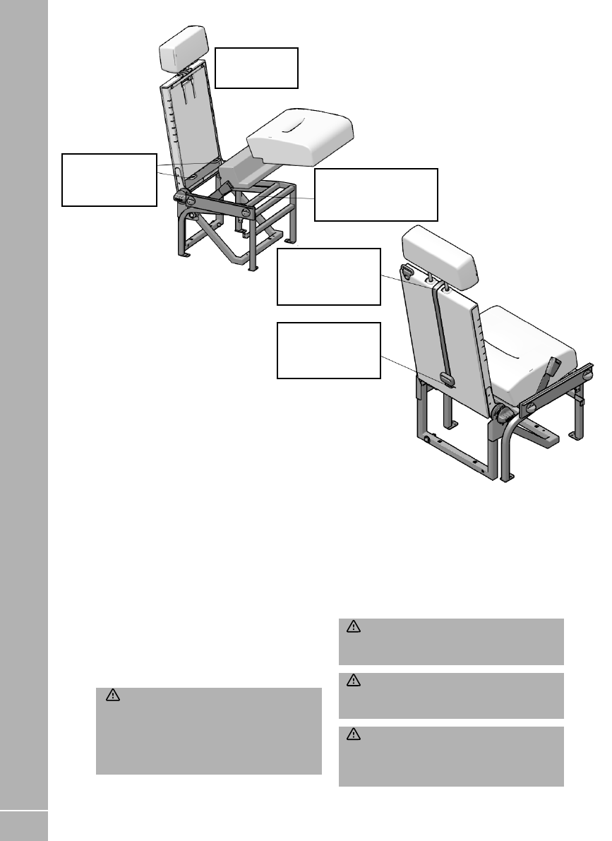
Voyager, Escape, Kon-Tiki 700 & 800 Series
ISOFIX anchorage points are provided on the
Aguti rear fold up seats. Top tether anchorage
points are located on the rear of the seat back.
To install a child restraint unfold the rear seat
until the back of the seat is between 10° and 15°.
Fit the base cushions ensuring that Velcro on the
cushion engages on the Velcro on the seat base
frame. Do not fit the seat back cushion.
PREPARING FOR THE ROAD
26
Follow the child restraint manufacturer’s
instructions for connecting the restraint to the
lower anchorage points and attaching the top
tethers. The top tethers must be routed over the
top of the seat but under the head rest.
WARNING: Please consult with the child
seat manufacturer’s instructions for full
installation instructions. If in doubt please
consult the child seat manufacturers technical
support team for further guidance on the
installation.
WARNING: Do not attach the top tether
strap to anything other than the correct top
tether strap anchor point.
WARNING: Make sure that the top tether
strap is not slack or twisted and is properly
located on the anchor point.
WARNING: Make sure the child restraint
rests tightly against the vehicle seat. You may
need to adjust the seats to properly secure the
child restraint.
PREPARING FOR THE ROAD
Location of child
restraint top tether
anchorage.
Top tether routed
over seat back but
under headrest.
Do not fit back
cushion.
Ensure Velcro® on
cushion engages with
Velcro® on frame.
Location of child
restraint lower
anchorages.

27
3.11 Three point seat belts
This section refers to the seat belts located in
the habitation area of your motorhome.
Fastening the seat belt:
Insert tongue into buckle; a positive ‘click’
indicates correct assembly.
Releasing the seat belt:
Press the red release button, the tongue will be
ejected from the buckle.
• The belt is designed for use by one person and
must not be put around a child seated on a
person’s lap.
• The belt is suitable for restraining most child
seats and boosters.
• The belt should at all times be adjusted and
used in accordance with the instructions. No
excessive slackness should be present.
• Once installed the diagonal should pass across
the centre of the shoulder and the buckle
should lie just on or below the hip.
Avoid twisting the webbing during use. Webbing
must not be allowed to chafe against sharp
edges.
• Do not make alterations or additions to the
belt.
• Belts that have been cut, frayed, damaged or
stressed through impact should be replaced.
After impact the motorhome anchorage points
should also be checked.
• To clean use warm soapy water only.
• Periodic inspection of the installation will
ensure reliability of the seat belt.
PREPARING FOR THE ROAD
Seating Position
Lateral
Facing
Rearward
Facing
Rearward
Facing
Forward
Facing
Rearward
Facing
0 - 10 kg 0 - 10 kg 0 - 13 kg 9 – 18 kg 9 – 18 kg
Front
Passenger
Size class
1
No ISOFIX
Fixture
1
2nd row RH
rear Seat
Size class X E C, D, E A, B, B1 C, D
Fixture X R1 R1, R2, R3 F2, F2X, F3 R2, R3
2nd row LH
rear seat
Size class X E C, D, E A, B, B1 C, D
Fixture X R1 R1, R2, R3 F2, F2X, F3 R2, R3
3rd row RH
rear seat
674, 774 &
874 only
Size class X X X A, B, B1 X
Fixture X X X F2, F2X, F3 X
ESCAPE, VOYAGER AND KON-TIKI 700 & 800 series ISOFIX CHILD RESTRAINT POSITION INFORMATION
1
The size class and fixture are defined for both universal and semi-universal child restraint systems.
You can see the identification letters on ISOFIX child restraints.
X Seat is not suitable for use with this size class of child restraint system.

28
PREPARING FOR THE ROAD
3.12 Driving licence
Licences issued to drivers who passed their car
driving test before 1st January 1997 include
categories B+E and C1+E which gives them
entitlement to drive motor vehicles up to 7500kg
MTPLM.
Drivers who passed their test on or after this
date have category B entitlement only, which
restricts the entitlement to motor vehicles with
up to 8 passenger seats and an MTPLM of up
to 3500kg with trailers up to 750kg MTPLM
(4250kg combined) or larger trailers providing
the combination of the trailer and towing vehicle
does not exceed 3500kg and the MTPLM of the
trailer does not exceed the unladen weight of
the towing vehicle.
Drivers who passed their test on or after the
1st January 1997 will need to take an additional
test(s) to gain the B+E and C1+E entitlement.
A number of Swift Group motorhomes have
an MTPLM greater than 3500kg, therefore you
must check you have the correct driving licence
entitlement for the vehicle you drive.
3.13 Advice on towing
The towing capability of each motorhome
differs depending on the specific chassis and
engine types, (see ‘Towing Capabilities’ in your
specification handbook).
This takes account of the maximum front and
rear axle loadings as well as the minimum front
axle loading in two conditions, MRO and MTPLM
condition.
Towing in these, and any other condition
requires sensible loading and distribution of
payloads to ensure the requirements of the
towing capability table are met.
When towing, the demands on both the
vehicle and driver increase. A trailer reduces
manoeuvrability, the ability to climb hills,
acceleration and braking capacity and makes
the vehicle handle and corner differently.
It will also increase the fuel consumption of
the vehicle.
Always brake in good time. Special care must
be taken when descending gradients. Change
down before going down a steep hill so the
engine can act as a brake. Ensure that the
towing vehicle tyre pressures are correct and
adjusted for full load conditions and that the
trailer tyre pressures are as recommended by
the trailer manufacturer. Regularly check the
operation of trailer brakes and lights.
For maximum stability, when loading the trailer
ensure that the loads are properly secured
during transit. Position loads so that most of
the weight is placed close to the floor and,
where possible, immediately above or close
to the axle(s). Where the load can be divided
between trailer and tow vehicle, loading more
weight into the vehicle will generally improve
the stability of the combination. After loading
the trailer, check that the nose weight and axle
loads are in accordance with the manufacturer’s
recommendations, also check the rear and front
axle loads on the motorhome. When calculating
the laden weight of the trailer, remember to
include the weight of the trailer PLUS THE
LOAD.
iNote: Towing regulations vary from country
to country. It is very important to ensure
that national regulations governing towing
weights and speed limits are observed (refer
to the relevant national motoring organisation
for information). The stated maximum
permissible towing weights refer to the

29
EN ROUTE
vehicle’s design limitations and NOT to any
specific territorial restrictions.
WARNING: The AL-KO extensions
fitted to the Edge vehicles are not suitable
for supporting a tow bar. Any tow bar and
supporting structure fitted must be connected
directly to the Fiat chassis. If a tow bar is
required we recommend that the Al-Ko tow
bar assembly, designed specifically for these
vehicles, is purchased and fitted by your Swift
motor home dealer.
WARNING: The chassis extensions fitted
to the Voyager vehicles are not suitable
for supporting a tow bar. Any tow bar and
supporting structure fitted must be connected
directly to the Ford chassis. Due to payload
restrictions Swift do not recommend towing
with the Voyager vehicles.
Notes:
1. Do not exceed the motorhome gross vehicle
train weight.
2. Do not exceed the maximum front & rear
axle loads on the motorhome.
3. Ensure the motorhome front axle load is
never less than 40% or more than 70% of the
total weight.
4. Motorhomes with an MTPLM up to 3500kg
which have European Type approval can
only be fitted with a type approved towbar
complying to ECE R55.
5. The limit for towing an un-braked trailer
is 750kg (based on VIN plate not actual
weight), this applies to a towed car.
6. A car dolly with a car with a GVW over
750kg in place is considered as two trailers,
these are legal for use for recovery but
under the Road Traffic Regulations Act
1984 the combination is limited to 40 mph
on motorways and dual carriageways
and 20 mph elsewhere. A car dolly is not
legal for transportation (there is a very
specific difference between recovery and
transportation. Recovery is defined as the
removal of a broken down vehicle to a place
of safety).
7. The maximum permitted vehicle
combination length is 18.75m, however
any combination must ensure compliance
with the turning circle requirements of
Construction and Use regulations 1986 &
(EU) No. 1230/2012.
3.14 European Touring
Please note there are a number of requirements
placed on a driver when driving on European
roads. Carrying a warning triangle, high
visibility jacket, first aid kit and spare bulb is
now compulsory in many EU states but some
EU countries are now introducing further
regulations such as carrying a breathalyser kit
and not being able to use satellite navigation
systems with speed camera warnings.
We would advise customers to check on the
many web-sites available to ensure you are
carrying the correct equipment when touring in
those EU countries.

30

31
4. En Route
4.1 Motorhome National Speed Limits . . . . . . . . . . . . . . . . . . . . . . . . . . . . . . . . . . 32
4.2 Cruise control . . . . . . . . . . . . . . . . . . . . . . . . . . . . . . . . . . . . . . . . . . . . . . . . . . . . . . 33
4.3 Parking sensors (where fitted) . . . . . . . . . . . . . . . . . . . . . . . . . . . . . . . . . . . . . . 33
4.4 Removal of spare wheel on ALKO conversion (where fitted) . . . . . . . . . . 33
4.5 Removal of Fiat spare wheel (where fitted) . . . . . . . . . . . . . . . . . . . . . . . . . . 34
4.6 Fiat Fix & Go Repair Kit (where fitted) . . . . . . . . . . . . . . . . . . . . . . . . . . . . . . . 35
4.7 Inflation Procedure (FIAT)(Where fitted) . . . . . . . . . . . . . . . . . . . . . . . . . . . . 36
4.8 Bottle Replacement Procedure (FIAT)(where fitted) . . . . . . . . . . . . . . . . . 37
4.9 Tyre Sealant and lnflator Kit (FORD)(where fitted) . . . . . . . . . . . . . . . . . . . 37
EN ROUTE

32
4.1 Motorhome National Speed Limits
The national speed limit for your motorhome
depends on the unladen weight of the vehicle
and whether or not the vehicle is towing a trailer.
The unladen weight of the vehicle is the weight
of the vehicle as delivered from the factory with
the fuel tank empty. It does not include any LPG
cylinders, water in the water tanks, personal
possessions or driver and passengers.
The unladen weight for your vehicle can be
found in the technical data handbook.
National Speed Limits
Vehicle Built-up
areas mph
Single
carriageways
mph
Dual
carriageways
mph
Motorways
mph
Motorhomes with an unladen weight of
3050 kg or less
30 60 70
70
Motorhomes with an unladen weight
greater than 3050 kg
30 50 60 70
All Motorhomes when towing a trailer
30 50 60 60
The speed limits given are national speed limits
for motorhomes and motor caravans being
used for their intended purpose. Be aware that
if the motorhome is being used to carry goods
for exhibition and sale, used as a workshop
or used for storage then it is classed as goods
vehicle and goods vehicle speed limits will apply
irrespective of the unladen weight.
WARNING: Local speed restrictions that
differ from the above may apply and must be
observed. These local restrictions will be
clearly signed.
EN ROUTE

33
4.2 Cruise control
The driver of the vehicle should always remain
seated and in control of the vehicle when cruise
control has been engaged. Never leave the
driving seat for any reason when the vehicle is
underway.
4.3 Parking sensors (where fitted)
Parking sensors (and camera based systems)
are fitted to some vehicles. Please use the
information provided. Use the sensors as a
guide only. It is the responsibility of the driver to
ensure it is safe to reverse the vehicle.
4.4 Removal of spare wheel on ALKO
conversion (where fitted)
WARNING: Exercise care when lowering
the wheel and frame due to its weight.
Removal
a. Spare wheel in the stowed position
(Fig. 1).
b. Remove the securing pins (a) from the
supports (b) at each side of the spare wheel
carrier frame (c) (Fig. 2).
c. Lift the wheel carrier frame (c) slightly and
move the frame supports (b) forward and
clear of the carrier frame (Fig. 3).
d. Lower the carrier frame and wheel to the
ground (Fig. 4).
e. Remove the spare wheel.
Replacement
Replacement is a reversal of the removal
procedure. Ensure the securing pins (a) are
correctly located in the frame supports (b).
Fig.1
Fig.2 Fig.3
Fig. 4
a
b
c
EN ROUTE

34
4.5 Removal of Fiat spare wheel
(where fitted)
a. The ground should be flat and adequately
firm.
b. Turn the engine off and engage the
handbrake.
c. Engage first gear or reverse.
Removal
a. Wheel restraining device screw (fig 1) – rear
right side of vehicle
b. Use the extension and wrench provided to
operate the wheel restraining device screw
(fig 2).
c. When the wheel is fully lowered (fig 3) and
the restraining device screw can turn no
more, use the wrench to pull the wheel out
d. (fig 4). Loosen the knob and remove the
support to release the wheel (fig 5 & 6).
Fig. 1
Fig. 2
iNote: It is possible that a transit zip tie may
still be in place. If wheel does not drop freely
check for zip tie.
Fig. 3
Fig. 4
Fig. 5
Fig. 6
Replacement
Replacement is a reversal of the removal
procedure.
WARNING: Exercise care when handling
the wheel due to its weight.
EN ROUTE
35
EN ROUTE
4.6 Fiat Fix & Go Repair Kit (where
fitted)
CAUTION: Before use please read the user
instructions supplied with your Fix & Go repair
kit.
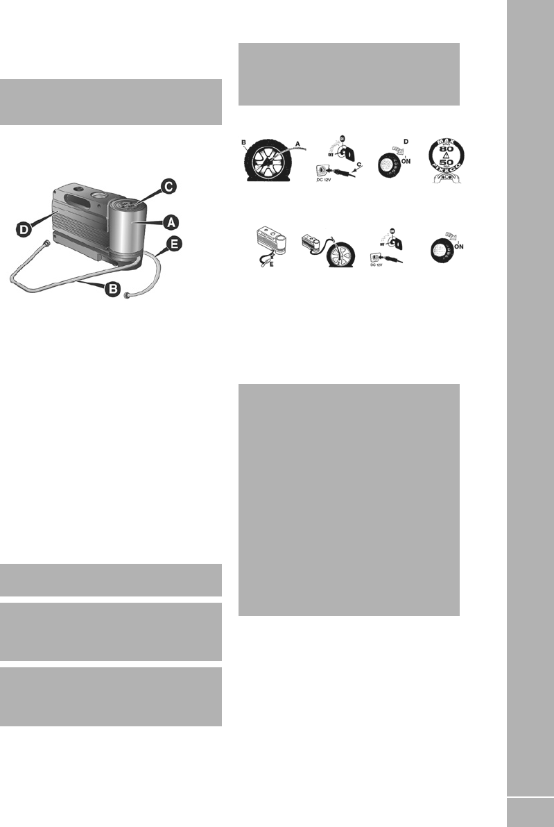
The Fix & Go automatic quick tyre repair kit is
positioned at the front of the vehicle assenger
compartment and includes Fig. A:
Fig.A
• Bottle A containing sealer and fitted with:
– a transparent filler pipe B;
– a black pressure restoring pipe E;
– sticker C bearing the notice “max. 80 km/h”, to
be placed in a position visible to the driver (on
the instrument panel) after fixing the tyre;
• Instruction brochure (see fig. b), to be used for
prompt and correct use of the quick tyre repair
kit and then to be handed to the personnel
charged with handling the tyre treated with
the tyre repair kit;
• A compressor D complete with pressure
gauge and connectors; a pair of protective
gloves located in the side compartment of the
compressor;
• Adaptors for inflating different elements
CAUTION: Give the instruction booklet to the
tyre repair workshop personnel.
CAUTION: Punctures on the sides of the tyre
cannot be repaired. Do not use the quick tyre
repair kit if the damage is due to running with
flat tyre.
CAUTION: If the wheel rim has been damaged
(bent so as to cause air to leak), the wheel
cannot be repaired. Do not remove the foreign
body (screws or nails) from the tyre.
iNote: Punctures caused by foreign bodies
can be repaired if the damage does not exceed
4 mm on the tread and on the shoulder of the
tyre.
Fig.B
Important Information:
The sealing fluid of the quick tyre repair kit is
effective at external temperatures of between
-20 °C and +50 °C. The sealant has an expiry
date.
CAUTION: The bottle contains ethylene glycol.
It contains latex that might cause allergic
reactions. It is harmful if swallowed. It is
irritant for the eyes. It may cause sensitisation
if inhaled or on contact. Avoid contact with
eyes, skin and clothes. In the event of contact,
wash immediately with plenty of water. Do
not induce vomiting if swallowed. Rinse your
mouth and drink plenty of water. Call a doctor
immediately. Keep out of the reach of children.
The product must not be used by asthmatics.
Do not breathe in the vapours during insertion
and suction. Call a doctor immediately if
allergic reactions are noted. Store the bottle
in its proper compartment, away from sources
of heat. The sealant has an expiry date on the
base of the bottle. Replace the bottle.

36
EN ROUTE
4.7 Inflation Procedure (FIAT)(Where
fitted)
CAUTION: Wear the protective gloves
provided together with the quick tyre repair kit.
CAUTION: Affix the adhesive label in an easy-
to-see position for the driver as a reminder
that the tyre has been treated with the quick
tyre repair kit. Drive carefully, particularly
on bends. Do not exceed 80 km/h. Do not
accelerate or brake suddenly.
CAUTION: If the pressure falls below 3
bars, do not drive any further: the Fix &
Go automatic quick tyre repair kit cannot
guarantee proper hold because the tyre is too
much damaged. Contact a Fiat Dealership.
CAUTION: You must inform the dealership that
the tyre has been repaired using the quick tyre
repair kit. Give the booklet to the personnel
who will be handling the tyre treated with the
repair kit.
CAUTION: If different tyres from the ones
supplied with the vehicle are used, it may
not be possible to carry out the repair. If the
tyres are replaced, it is advisable to use those
approved by the manufacturer. Consult a Fiat
Dealership.
• Pull the handbrake. Unscrew the tyre valve
cap, take out the filler hose A (Fig. C) and
tighten the ring nut B on the tyre valve;
• Insert the plug E (Fig. E) in the nearest 12V
power socket and start the engine. Turn the
selector D (Fig. D) anti-clockwise to the repair
position. Activate the kit by pressing the on/
off switch. Inflate the tyre to the pressure
specified in the “Inflation pressure” paragraph,
in the “Technical Data” chapter;
For a more accurate reading, it is advisable to
check the pressure reading on the pressure
gauge F (Fig. D) with the compressor off and
without moving the centre selector from the
repair position
Fig C
Fig D
• If after 10 minutes it is still impossible to reach
at least 3 bar, release the transparent filler
pipe from the valve and take out the 12 V plug,
then move the vehicle forwards by about 10
metres in order to distribute the sealing fluid
inside the tyre evenly, then repeat the inflation
operation;
• If after this operation you still cannot reach at
least 3 bar after 10 minutes, do not resume
driving because the tyre is too damaged and
the quick tyre repair kit cannot guarantee
suitable sealing. Contact a Fiat Dealership;
• If the tyre reaches the pressure specified
in “Inflation pressure” paragraph in the
“Technical Data” section of the Fiat user
manual start driving immediately;
Fig
E

37
EN ROUTE
After having driven for about 10 minutes, stop
and recheck the tyre pressure; remember to
apply the handbrake;
If a pressure value of at least 3 bar is detected,
inflate to the correct pressure, resume driving
and drive with care to nearest Fiat Dealership.
4.8 Bottle Replacement Procedure
(FIAT)(where fitted)
To replace the bottle, proceeds follows:
Fig. F
Press button A (Fig. F) to release the part;
Fit the new bottle and press until it is
automatically engaged.
CAUTION: Replace the bottle containing the
sealant after the expiry date. Expiry date is
shown on the base of the bottle. Dispose of
the bottle and the sealant properly. Have
the sealing fluid and the bottle disposed
of in compliance with national and local
regulations.
4.9 Tyre Sealant and lnflator Kit
(FORD)(where fitted)
What is the tyre sealant and inflator kit
The kit consists of an a air compressor to
re-inflate the tyre and a canister of sealing
compound that effectively seals most
punctures. This kit provides a temporary tyre
repair allowing you to drive your vehicle up to
200km (120 mi) at a maximum speed of 80 km/h
(50 mph) to reach a tyre service location.
Tyre sealant and inflator kit precautions
WARNING: Depending on the type and
extent of tyre damage, some tyres can only
be partially sealed or not sealed at all. Loss
of tyre pressure can affect vehicle handling,
leading to loss of vehicle control.
WARNING: Do not use the kit on a
previously damaged tyre. For example, when
it has been driven under-inflated. This when it
could has cause been loss of vehicle control,
personal injury or even death.
Do not attempt to repair punctures larger than
6mm (0.24 in) or damage to the tyre’s sidewall.
Only punctures located within the tyre tread can
be sealed with the kit.
Only use the kit supplied with your vehicle.
The temporary mobility kit contains enough
sealant compound in the canister for one tyre
repair only.
After using the sealant, an authorised dealer
needs to replace the tyre pressure monitoring
system sensor and valve stem on the wheel.

38
EN ROUTE
B
E146784
A) Protective cap
B) Pressure relief valve
C) Hose
D) Pressure gauge
E) Power plug with cable
F) Compressor switch
G) Label
H) Sealant bottle
iNote: Make sure you regularly check the
expiry date on the sealant bottle.
Using the tire sealant and inflator kit
WARNING: The sealant contains natural
rubber latex. Avoid contact with skin and
clothing. If this happens. rinse the affected
areas immediately with plenty of water and
consult a physician.
WARNING: Do not leave the kit unattended
when it is in use. Failure to follow this
instruction could result in personal injury or
death.
WARNING: Check the sidewall of the
tyre prior to inflation. If there are any cracks.
bumps or similar damage, do not attempt to
inflate the tyre. This could cause personal
injury.
1. Check for a punctured tyre.
iNote: Do not remove objects. For example,
nails or screws from a punctured tyre.
2. Open the lid of the tyre sealant and inflater
kit.
3. Peel off the label G showing the maximum
permissible speed of 50 mph (80 km/h) from
the casing and attach it to the instrument
panel in the driver’s field of view. Make
sure the label does not obscure anything
important.
4. Take the hose C and the power plug with
cable E out of the temporary mobility kit.
5. Screw the hose C onto the sealant bottle.
6. Remove the valve cap from the damaged
tyre.
7. Remove the protective cap A from the
sealant bottle hose and screw the hose
firmly onto the valve of the damaged tyre.
8. Make sure that the compressor switch F is in
position O.
9. Insert the power plug E into the auxiliary
power point.
10. Start the engine.
WARNING: Do not stand directly beside the
tyre while the compressor is operating. This
could cause personal injury if the tyre bursts.
11. Move the compressor switch F to position 1.
12. After a minimum of two minutes, move
the compressor switch F to position 0 and
unscrew the hose C from the sealant bottle.
Unscrew the sealant bottle hose from the
tyre valve.
13. Screw the hose C onto the tyre valve and
move the compressor switch F to position 1.
WARNING: Watch the sidewall of the tyre
when inflating. If any cracks, bumps or similar
damage appears, switch the compressor off
and let the air out by means of the pressure
relief valve. Do not continue driving with this
tyre. This could cause loss of vehicle control.
WARNING: Do not keep the compressor
operating for more than 10 minutes. This could
cause the compressor to malfunction causing
serious personal injury.

39
SAFETY AND SECURITY
5. Safety and Security
5.1 Fire . . . . . . . . . . . . . . . . . . . . . . . . . . . . . . . . . . . . . . . . . . . . . . . . . . . . . . . . . . . . . . . . 40
5.2 Fire Extinguisher . . . . . . . . . . . . . . . . . . . . . . . . . . . . . . . . . . . . . . . . . . . . . . . . . . . 40
5.3 Escape paths . . . . . . . . . . . . . . . . . . . . . . . . . . . . . . . . . . . . . . . . . . . . . . . . . . . . . . . 40
5.4 Children . . . . . . . . . . . . . . . . . . . . . . . . . . . . . . . . . . . . . . . . . . . . . . . . . . . . . . . . . . . 40
5.5 Ventilation . . . . . . . . . . . . . . . . . . . . . . . . . . . . . . . . . . . . . . . . . . . . . . . . . . . . . . . . . 41
5.6 CO alarm . . . . . . . . . . . . . . . . . . . . . . . . . . . . . . . . . . . . . . . . . . . . . . . . . . . . . . . . . . . 41
5.7 Security . . . . . . . . . . . . . . . . . . . . . . . . . . . . . . . . . . . . . . . . . . . . . . . . . . . . . . . . . . . . 41
5.8 Swift Command Tracker by Sargent (where fitted) . . . . . . . . . . . . . . . . . . . 42
5.9 VIN CHIP™ . . . . . . . . . . . . . . . . . . . . . . . . . . . . . . . . . . . . . . . . . . . . . . . . . . . . . . . . . 43

40
5.1 Fire
iNote: Your attention is drawn to the notice
affixed inside the wardrobe advising on fire
precaution, ventilation and what to do in case
of fire.
In case of fire
Get everyone out of the motorhome as quickly
as possible using whichever exit is the quickest,
including windows. Do not stop to collect any
personal items.
Raise the Alarm. Call the Fire Brigade.
Turn off the gas supply valve if it is safe to do so.
Turn off the electricity supply at supply point.
Smoke Alarm Operation
Your motorhome is fitted with a Fire Angel SB1
smoke alarm. Please read the user instructions
for the smoke alarm, which are available at the
following location:
https://www.fireangel.co.uk/products/sb1-t
If you are unable to view the documents on line,
please contact the supplier, your dealer or Swift
for an electronic or paper copy.
WARNING: Never use portable cooking or
heating equipment other than electric heaters
that are not of the direct radiant type, as it is a
fire and asphyxiation hazard.
WARNING: Appliances such as cookers
must not be used for heating.
5.2 Fire Extinguisher
It is recommended that a dry powder fire
extinguisher be carried inside your motorhome
at all times.
When using a dry powder extinguisher it is
suggested that the motorhome be evacuated
until the powder has settled, to avoid inhalation.
A fat pan fire should not have a fire extinguisher
aimed at it. It should be smothered with a fire
blanket.
WARNING: Provide one dry powder fire
extinguisher of an approved type or complying
with EN3-7 or ISO 7165, of at least 1kg
capacity, by the main exterior door and a fire
blanket next to the cooker. Familiarise yourself
with the instructions on your fire extinguisher
and the local fire precaution arrangements.
5.3 Escape paths
It is important that you do not block escape
paths to emergency exits with obstructions or
hazards.
5.4 Children
Do not leave children alone in the motorhome in
any event. Keep potentially dangerous items out
of reach, as at home e.g. matches, medicine etc.
SAFETY AND SECURITY

41
SAFETY AND SECURITY
5.5 Ventilation
All motorhomes comply with BS EN 721. The
ventilation points on your motorhome are fixed
points of ventilation which are required by the
European Standards.
All motorhomes have ventilation at high level
and low level which have been calculated to suit
the individual needs of your motorhome.
High level ventilation is achieved by means of
the roof lights and washroom roof ventilators
(where applicable). The low level ventilators are
positioned under sink units/fridge cupboards.
Under no circumstances must these vents be
blocked or obstructed in any manner as this
could lead to insufficient fresh air. In this case
the confined atmosphere becomes depleted of
oxygen which could lead to dangerous levels of
carbon dioxide (CO2) build up leading to the risk
of asphyxiation.
The risks of carbon monoxide (CO) build up,
which is a colourless, odourless and tasteless
gas, will also be reduced with ventilation.
Carbon monoxide is produced from incomplete
combustion and should the CO detector
be activated the cause of the incomplete
combustion must be investigated prior to
reusing the appliance in question.
It is advised that fixed ventilation points are
checked and cleaned (if necessary) on a regular
basis using a small brush and a domestic
vacuum cleaner.
Additional night time ventilation is obtained by
releasing the window catches and placing them
in the second groove. Note the windows are not
sealed from rain in this position.
As the ventilation levels are calculated to suit
each model requirements no modifications
should be made which may result in reduced
ventilation levels.
WARNING: Do not obstruct ventilation.
5.6 CO alarm
Your motorhome is fitted with a Fireangel CO-
9XT-FF Carbon Monoxide Alarm. To activate
the alarm, you will need to pull the disabling
tab as shown in the above image. For further
information, please read the instructions for
the alarm, which are available at the following
location:
https://www.fireangel.co.uk/product/co-9xt-ff/
If you are unable to view the documents on line,
please contact the supplier, your dealer or Swift
for an electronic or paper copy.
5.7 Security
Motorhome theft:
The theft of a motorhome can occur in the
most unlikely circumstances; from a motorway
service area or even an owner’s driveway.
Secure all windows and doors when your
motorhome is unoccupied even if only for a short
length of time.
VIN (Vehicle Identification Number)
Record your motorhome VIN. This can be found
at the bottom of the windscreen, on the Swift
and Ford plates on the passenger cab door B
pillar or on the Fiat plate on front cross member
within the engine compartment.
Make a note of these numbers in the space
provided at the front of this handbook and make
a separate note of the numbers to keep safe at
home.

42
SAFETY AND SECURITY
Additional security
Consider fitting any device which might deter
intrusion by thieves. Customers are advised
to identify their motorhome with a method
for subsequent identification if other forms of
identification have been altered or removed.
Free crime prevention advice about securing
your motorhome, protecting your valuables,
property marking either at home or whilst on
site, can be obtained from the Crime Prevention
Officer through your local Police station.
5.8 Swift Command Tracker by
Sargent (where fitted)
A Swift Command Tracker when built into
your vehicle forms part of the Swift Command
system.
The unit is Thatcham Category S7 certified and
is monitored by an approved monitoring centre
which operates 24 hours a day 7 days a week
and provides European coverage and direct
police liaison.
This system is ready for use, all you need to do
is purchase a tracking subscription by visiting
www.swiftcommand.co.uk or calling Sargent on
01482 881655.
For more information including subscription
costs please visit:
www.swiftcommand.co.uk
Operation
The Swift Command Tracker is easy to operate
as it is controlled by the vehicle systems.
In a motorhome the tracker is armed / disarmed
by the ignition key.
When the ignition is turned off the tracker
is armed. When the ignition is turned on the
tracker is disarmed.
Event of a Theft
If the vehicle is moved whilst the tracker is
armed the geo-fence monitoring will trigger a
theft event.
The monitoring station will now contact you
to confirm the theft or false alarm. You will be
required to confirm your identity against the
information you provided when you subscribed.
If a genuine theft is confirmed the monitoring
station will liaise with the police and keep you
informed of progress.
iNote; during a theft event to comply with
legislation you will not be able to manually
locate your vehicle using the Swift Command
locate feature.
Contact
Before contacting any of the following please
ensure you know your caravan or motorhome
serial number. For motorhomes this is the
unique MH number (like MH01234).
The Swift Command Tracker monitoring station
can be contacted on 0345 6027302. The stations
operates 24 hours a day 7 days a week.
Sargent customer support can be contacted on
01482 678981 or via support@ swiftcommand.
co.uk
Telephone lines are manned during normal
office hours.
Swift customer support can be contacted on
01482 875740 during normal office hours.
Precautions
The Swift Command Tracker monitors the
leisure battery supply and if the voltage falls
below a set level or the battery is removed this
will trigger a fault event.
If you plan to remove your battery for
maintenance or external charging please
contact the monitoring station BEFORE
removing the battery.
If you lose an ignition key you will need to visit a
Fiat dealer for key replacement and removal of
the ‘lost’ key.

43
SAFETY AND SECURITY
5.9 VIN CHIP™
Your motorhome has been securely marked and
the VIN recorded with VIN CHIP™.
VIN CHIP™ is the industry standard security
marking system for touring caravans and
motorhomes.
Shortly after purchasing this motorhome.
you will receive via email your VIN CHIP™
registration document. This document will
include the 17 digit VIN (vehicle identification
number) and other relevant details about
your motorhome. If you sell your motorhome,
please follow the instructions on the VIN CHIP
motorhome document.
VIN CHIP identification
The motorhome’s unique 17 character VIN will
be incorporated into VIN CHIP tamper evident
labels;
The master VIN CHIP label is situated on the
front near side window to aid police checking,
another in the gas locker and a maximum of 10
placed on the inside of the windows (with the
exception of opaque windows).
Three electronic RFID chips containing the
individual identity of your motorhome are
concealed within the vehicle and can only be
read by using a specially programmed RFID
scanner.
Your local police can obtain the use of a VIN
CHIP™ scanner by contacting VIN CHIP on
tel: 0333 2124746.
For help, support and advice, contact:
VIN CHIP
PO Box 445
Aldershot
GU11 9SF
Tel 0333 2124746
www.vinchip.co.uk

44
SAFETY AND SECURITY

45
ARRIVAL AT SITE
6. Arrival at the site
6.1 Positioning the motorhome . . . . . . . . . . . . . . . . . . . . . . . . . . . . . . . . . . . . . . . . . 46
6.2 Awnings and Tents . . . . . . . . . . . . . . . . . . . . . . . . . . . . . . . . . . . . . . . . . . . . . . . . . 46

46
ARRIVAL AT SITE
6.1 Positioning the motorhome
iNote: Check and observe site regulations.
Keep to roadways unless otherwise directed.
Adhere to speed limits. Note that these are
generally 10mph.
(Remember that the stopping distance on grass
is considerably greater than on tarmac.)
Only a person in possession of a current driving
licence may drive on the site.
Selecting a pitch
Do not pitch in such a position that your
motorhome will obstruct others coming in.
Try to choose an area which is dry, reasonably
level and preferably with a hard base.
If you have no alternative but to pitch on a slope
try to ensure that you are facing down the slope,
for when you leave.
Levelling the motorhome
Levelling must be carried out in both directions
for the refrigerator and other equipment to
function correctly. Stepped levelling boards
(Fig. A) or proprietary ramps are ideal for this
purpose. Levelling pads or boards should be
used under the wheels where the ground is soft
or uneven.
Fig. A Stepped levelling board
6.2 Awnings and Tents
Awnings and tents should only be used when
permission has been obtained. When on grass
and staying for more than a few days the ground
sheet and/or side flaps of awnings should be
periodically raised in order to avoid damage to
the ground.

47
SERVICES
7. Services
7.1 Water system - Introduction . . . . . . . . . . . . . . . . . . . . . . . . . . . . . . . . . . . . . . . . 48
7.2 Fresh water system . . . . . . . . . . . . . . . . . . . . . . . . . . . . . . . . . . . . . . . . . . . . . . . . . 49
7.3 Priming the Water System . . . . . . . . . . . . . . . . . . . . . . . . . . . . . . . . . . . . . . . . . . 50
7.4 Cleaning water system . . . . . . . . . . . . . . . . . . . . . . . . . . . . . . . . . . . . . . . . . . . . . 51
7.5 Pressure switch . . . . . . . . . . . . . . . . . . . . . . . . . . . . . . . . . . . . . . . . . . . . . . . . . . . . 52
7.6 Waste water system . . . . . . . . . . . . . . . . . . . . . . . . . . . . . . . . . . . . . . . . . . . . . . . . 53
7.7 Tank heaters . . . . . . . . . . . . . . . . . . . . . . . . . . . . . . . . . . . . . . . . . . . . . . . . . . . . . . . 53
7.8 Water level sensor & cleaning . . . . . . . . . . . . . . . . . . . . . . . . . . . . . . . . . . . . . . . 54
7.9 Water fault finding . . . . . . . . . . . . . . . . . . . . . . . . . . . . . . . . . . . . . . . . . . . . . . . . . . 55
7.10 Gas . . . . . . . . . . . . . . . . . . . . . . . . . . . . . . . . . . . . . . . . . . . . . . . . . . . . . . . . . . . . . . . 59
7.11 Types of gas . . . . . . . . . . . . . . . . . . . . . . . . . . . . . . . . . . . . . . . . . . . . . . . . . . . . . . . 60
7.12 En-route heating (where fitted) . . . . . . . . . . . . . . . . . . . . . . . . . . . . . . . . . . . . 61
7.13 Gas safety advice . . . . . . . . . . . . . . . . . . . . . . . . . . . . . . . . . . . . . . . . . . . . . . . . . . 62
7.14 Gas fault finding . . . . . . . . . . . . . . . . . . . . . . . . . . . . . . . . . . . . . . . . . . . . . . . . . . . 64
7.15 The electrical system . . . . . . . . . . . . . . . . . . . . . . . . . . . . . . . . . . . . . . . . . . . . . . 65
7.16 230V mains electrical equipment power consumption . . . . . . . . . . . . . . . 66
7.17 Wiring of connecting cable and motorhome mains inlet . . . . . . . . . . . . . 67
7.18 Typical appliance consumption figures . . . . . . . . . . . . . . . . . . . . . . . . . . . . . 68

48
SERVICES
7.1 Water system - Introduction
General advice
All Swift Group motorhome water systems
have been designed around a pump fitted
within the motorhome. This pump draws water
from an under floor or internal water tank,
to provide water pressure within the water
system, whenever it is switched on and water is
available.
The schematic below shows the basic
configuration of the water system:
When power is supplied to the pump, it will draw
water from the water tank, and pump it to the
motorhome taps, shower and water heater.
The pump is fitted with its own pressure switch,
and will continue to pump water, until the
pressure of water on the output of the pump
reaches a pre-set level. For this pressure to be
achieved, the taps must be closed.
When the taps are opened, water will leave the
tap via the spout, and the pressure in the pipes
between the pump and the taps will reduce.
Because of this reduction in pressure, the
pressure switch on the pump will switch back
on and the pump will again run to pump more
water.
Close to the pump, the water under pressure is
split into two paths:
Through blue water pipes routed directly to the
cold connection of each tap.
To the water heater.
Water from the pump enters the bottom of the
water heater. Once the water fills the water
heater (typically 10 litres), water then leaves
the water heater via a connection at the top of
that water heater. This water, which is still under
pressure, then routes to the hot connection of
each tap via the red pipes.
To winterise the system please see separate
details later in this handbook.

49
SECURITY
7.2 Fresh water system
All fittings, including the holding tank, water
pipes, taps and connections are of food quality
material (to BS6920) and therefore, should
not affect the quality of the water used. It is
recommended however, that the system is
flushed through twice before it is used for the
first time, and always cleaned/flushed after it
has stood unused for a period of time (eg over
the winter period). Care has been taken (using
smooth bore pipes etc) to eliminate as many
water traps as possible.
When filling the fresh water system remember
to check that the water source is suitable for use
as drinking water. If possible avoid using water
sources which use desalination or other similar
processing, as they may contain chemicals that
could damage the stainless steel components
within your motorhome water system. If in
doubt, check locally before using a water supply.
If you are using a hose pipe or water carrier,
ensure this is made from nontoxic materials
(preferably food grade material)
Motorhome Water Tank Drains
Depending on the specification, the fresh water
tank will be fitted with either a bung in the
bottom of the tank, or a manually or electrically
operated drain valve. Check the bung is in place,
or the valve is closed, before filling the fresh
tank:
Edge models
To remove the bung, first remove the tank
lid and then carefully pull on the chain which
secures the bung to the inside of the tank. Keep
the bung clear of the drain hole until the tank is
empty, and replace before re-filling the tank.
Voyager models
Locate the blue plastic drain valve on the rear
offside of the vehicle under the side skirt and
turn the tap to open or close the valve.
Escape and Ascari models
Controls for the electrically operated drain
valves are present in the upper kitchen
cupboard, valves on the fresh and waste tanks
can be controlled separately.
An LED indication on each switch will show
whether the drain valve is open (Amber LED) or
closed (Green LED).
Kon-Tiki models
The electrically operated drain valves are
normally closed. On the control panel above
the door, it is possible to check this: The ‘empty
fresh’ and ‘empty waste’ buttons will be flashing
if the valve is open, and will not flash if the
valve is closed. Press the button on the touch
screen to open or close the valve. See the Swift
Command instructions later in this handbook for
further details.
Boiler / Water System Drain
The boiler / water system drain valve is located
close to Alde or Truma heating appliance. To
drain the system lift the yellow handle to the
vertical position (f) The drain is closed when the
handle is in the horizontal position (e).

50
SERVICES
WARNING: The fresh water system is
pressurised by a pump which will continue to
operate until it senses a pre-set pressure in
the system.
If the fresh water tank is completely empty the
pump will be unable to pressurise the system
and will operate continuously. In this situation
it is essential that, in order to avoid damage
to the pump, it is switched off using the pump
isolator switch on the distribution panel until
such time as the water tank has been filled.
Fresh Water Tank
Your motorhome is fitted with a water tank filled
from the outside via a lockable water filler cap.
When filling, use a hose manufactured from non
toxic material, to prevent tainting of the water.
Remember, if the water heater has been drained
it will require 10 litre (0.2 gal) of water to fill it.
External 12v Fill Socket
Depending on specification your motorhome
may be fitted with an external 12v socket which
can be used to attach an external 12v tank filling
pump.
7.3 Priming the Water System
When water is first introduced, or the water
supply in the internal tank, runs out, air will be
present in the pipework. It is important that
every tap is run to remove any air in the system
before, for instance, the shower is used. Air
left in pipework local to a tap can act as an
accumulator and affect the ratio of hot and cold
water flowing from other taps or shower mixers
in the system.
1. Close the fresh water tank drain valve.
2. Fill the water tank with water.
3. Close the water heater drain valve (see
boiler instructions in the fitted equipment
section)
4. Open all the taps except the shower tap.
Mixer taps should be opened in the central
position so that both the hot and cold pipes
are purged of air. Ensure the tap spouts are
over the sinks.
5. Turn on the pump using the button on the
control panel above the entrance door.
6. Turn each tap off in turn as and when the air
is expelled and the water runs smoothly from
each tap. Move the mixer taps to hot and then
cold to check that the air is out of both the hot
and cold pipes before turning them off.
7. Whilst holding the shower head down
towards the shower drain, open the shower
tap and shower head tap until all the air is
expelled and the water runs smoothly. Turn
the shower taps off.
8. Top up the fresh tank with water.
Please note that priming the system will
automatically fill the water heater with water.
Please ensure all taps are fully turned off when
not in use (except when winterising).
iNote: All tanks are fitted with a breather
which acts as an overflow. Overfilling a tank
will result in water being expelled from the
overflow outside the vehicle.

51
7.4 Cleaning water system
Clean the water system at the start and end of
the season with sterilising fluid.
Sterilising
When cleaning the water system at the start
or the end of the season it is advisable to use
a suitable sterilising fluid available from your
motorhome dealer. The fluid must be suitable
for use with stainless steel components
Flush the system thoroughly to remove the
effective fluid traces.
When water is first introduced, or the water
supply in the internal tank, runs out, air will be
present in the pipework. It is important that
every tap is run to remove any air in the system
before, for instance, the shower is used. Air
left in pipework local to a tap can act as an
accumlator and affect the ratio of hot and cold
water flowing from other taps or shower mixers
in the system.
Edge fresh water tank showing central
cleaning hatch
System care
Allowing water to freeze in the system may
result in damage to the pump and plumbing
system.
Non-Toxic antifreeze for potable water may be
used with Truma pumps. Follow manufacturers
recommendations.
Do not use automotive antifreeze to winterize
potable water systems.
These solutions are highly toxic and may cause
serious injury or death if ingested.
Sanitising
The water systems, and in particular storage
tanks, in motorhomes are susceptible to
contamination by bacteria if care is not taken
with their use and cleaning. The symptoms
caused by bacterial contamination are not
purely limited to gastro-intestinal diseases,
but may also manifest themselves as ear, nose,
throat, eye or skin infections. It is therefore
important that you carry out the following
procedure prior to using the motorhome each
time, even if you boil or filter all water you use
for drinking.
Separate Water Containers
1. All water remaining in the container should
be disposed of so that the container is empty.
2. The outside of the container should be
thoroughly cleansed and washed down to
remove any dirt, dust or other contaminant.
Water at a suitably hot temperature
containing an appropriate detergent is
recommended for this purpose.
3. Water should be put in the container, swirled
around, then emptied out.
4. The container should then be totally filled
with water containing an appropriate
sterilant solution and allowed to stand for
the recommended contact time.
5. The solution should be emptied from the
container.
6. The opening of the container should be
cleaned thoroughly with an appropriate
prepared wipe impregnated with a sterilant.
SERVICES
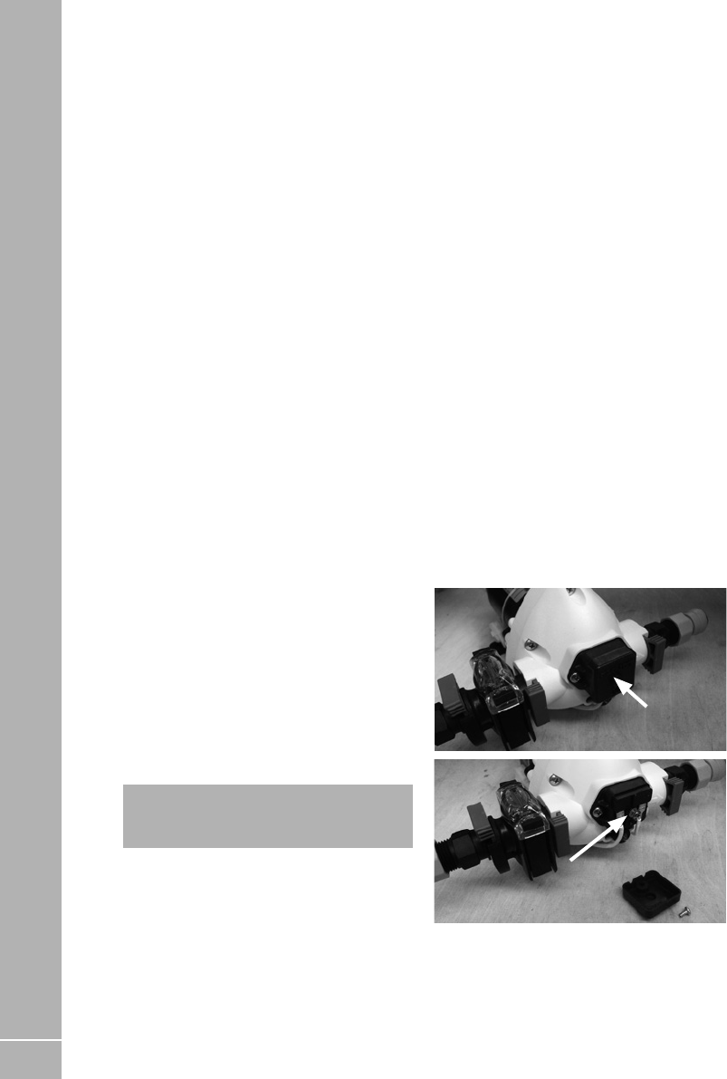
52
7. The container should be inverted whilst
stored overnight (if possible).
8. The container must be filled with mains
water only and mains water only should be
used for the above cleaning procedure.
9. On no account should garden hoses be used
to fill water tanks.
For Systems:
1. Drain down the system (open all taps to
allow air in, enabling the system to drain
quickly).
2. Remove any water filters fitted, and replace
with a short length of hose or empty filter
cartridge (this will ensure the filter is not
affected by the disinfectant/ sterilant
solution).
3. Fill the water system with a disinfectant/
sterilant solution (check that the solution at
full strength appears at all taps/showers).
Allow to stand for the recommended period
of time.
4. Drain the system completely.
5. Thoroughly clean the outside of all taps/
connectors with a cloth soaked in the
disinfectant/sterilant.
6. Flush the system through with clean drinking
water until no traces of disinfectant/sterilant
can be detected at any tap.
Suitable sterilising chemicals are available
from your motorhome dealer, accessory shop,
chemist or home-brew shops. It is not, however,
recommended to use bleach or sodium
metabisulphite.
Sterilising
Do not use products that contain aggressive
agents for sterlising the water system. Always
use products designed for stainless steel tanks
available from your motorhome dealer.
iNote: Never use the water heating system
when disinfectant/sterilising fluid is present.
Doing so may damage the system.
7.5 Pressure switch
The purpose of a pressure switch is to monitor
the pressure on the outlet side of the pump.
When a tap is closed, and the pump continues
to run, there is an increase of pressure in the
system, and when that pressure reaches a
pre-set limit, the pressure switch will turn the
pump off.
Pressure switch adjustment
Pressure Switch Adjustment, Truma/Flo-Jet
pump. (Normally Grey upper section with White
lower section/valve housing)
• All of the Truma/Flo-Jet pumps used by Swift
are pre-set at 25psi - 31psi.
• To further adjust the pressure switch setting,
a cover cap must be first be removed from the
end of the pump to reveal a pressure adjusting
screw, as shown in the photos. A maximum
of 1/4 turn clockwise or anti-clockwise, from
the factory setting, is advised. Turning the
screw clockwise 1/4 turn will increase the
pressure switch cut-out pressure, turning the
screw anti-clockwise will reduce the pressure
setting.
• Please note a second screw mounted below
the cover cap is set in position with threadlock,
this should not be disturbed.
Cover cap
Pressure switch
adjusting screw
The pump may have to be removed to gain
access to the adjusting screw. Drain the water
system before removing the pump.
To remove the pump pull the blue taps at right
angles to the pipe work and lift the pump out.
SERVICES

53
7.6 Waste water system
1. The waste water holding tank is secured
below the floor of the motorhome, and is
gravity fed.
iNote: Should the waste water tank be
overfilled, it is possible that waste water will
backfill the pipes until it eventually appears
in the shower tray. In order to prevent this,
please monitor the water level gauges on the
motorhome control panel. It is also possible
to to enable a ‘waste tank full’ alarm, on the
control panel.
2. Depending on the specification, the waste
water tank will be fitted with either a
manually or electrically operated drain valve.
Edge and Voyager models
A grey manually operated drain valve will be
located externally, close to the motorhome skirt.
Escape and Ascari models
Controls for the electrically operated drain
valves are present in the upper kitchen
cupboard.
An LED indication on each switch will show
whether the drain valve is open (Amber LED) or
closed (Green LED).
Kon-Tiki models
The electrically operated drain valves are
normally closed. On the control panel above
the door, it is possible to check this: The ‘empty
waste’ button will be flashing if the valve is open,
and will not flash if the valve is closed. Press the
button on the touch screen to open or close the
valve. See the Swift Command instructions later
in this handbook for further details.
7.7 Tank heaters
Depending on specification, your motorhome
may be fitted with 12v tank heaters, designed to
prevent or reduce instances of freezing water in
fitted water tanks.
If tank heaters are fitted, they can be turned on
via the control panel above the entrance door.
For Edge, Ascari and Escape the control is a
button on the fascia of the EC400+ control panel.
For Kon Tiki the control is in the water system
page of the EC800 touch screen control panel.
Turn the feature on when external temperatures
are low, and the tank heaters will then provide
heat automatically, and only when required.
Before heating each tank the system will check
that the water level in each tank is at the 1/4
level or higher (the heaters will not operate
if the tank is ‘empty’). If the water level is
appropriate, the heaters will then switch on and
off depending on temperature.
As the tank heaters check the water level in each
tank, the fresh and waste water tank heaters
can operate independently, for instance use of
frost protect feature while the fresh tank is full,
but waste tank is empty, would only result in the
operation of the fresh tank heater.
It is also possible to use the tank heaters en-
route, i.e. while driving. With the control panel
ON, turn on the tank heaters as described above.
While the engine is running the control panel
cannot be operated, however, the tank heater
circuits will remain ON.
Please note that the heating elements use a 12V
supply. With the engine off, and if used without
a mains hook up and charger operating, then
leisure battery power consumption will be
increased (see consumption table on page 64
for more information).
SERVICES

54
7.8 Water level sensor & cleaning
Principle
The sensor, fitted to Swift Group motorhomes
are pre-fitted to water tanks, and link to the
control unit, via a pre-fitted wiring harness. The
sensors, which consist of a number of stainless
steel rods or probes, at different lengths, are
immersed in the fresh or waste water, and use
the conductivity of water, between the probes,
to provide a reading to the control unit.
The sensors are ‘digital’, in that while the
conductivity (resistance) value can vary, the
fusebox will register any conductivity between
the reference probe and the various different
length probes, indicating water present.
Normally, even if the rods are dirty, and
providing the rods have not bridged by a foreign
object, a circuit will still be delivered back to the
control unit and a water level displayed.
Sensor cleaning
The first step, in case of fault diagnosis, is
to clean the sensor rods. False water level
readings at the control unit can be caused by
calcium build-up or foreign objects within the
tank bridging the probes. (Especially with waste
tanks).
To clean sensor:
WARNING: Only use food safe plastic mesh
scourers, which are suitable for domestic use,
for cleaning the sensor studs.
1. Remove the sensor from the tank
2. Check the probes for build up of
contamination
3. Use clean, soapy water
4. Place scourer in water to dampen
5. Apply scourer to the sensor probes with
limited pressure
6. Rub sensor probes, removing contamination
7. Swill sensor probes with fresh, clean water
8. Replace sensor into tank.
iNote: Tank levels are measured in
increments of 25%
SERVICES

55
SERVICES
Fault Cause Remedy
Water not flowing from
any tap when operated
but pump runs
Freshwater tank empty
Water system not primed
Pump wired in reverse
Pipe inlet or outlet pipe disconnected
Pump pipes restricted by kinking
Blocked pump filter
Air leak in suction line to pump
Frozen pipes
Low voltage
Check
Ensure water system has been primed
correctly, (see priming the water system
section 7.3), and there are no air-locks
present
Check wiring, refer to pump
manufacturer’s instructions
Check connections
Check pipe runs
Check, starting at the freshwater tank
Dismantle and clean filter. See pump
manufacturer’s instructions.
Check condition of pipe and pipe joints
between the water tank and the pump.
Defrost pipes
Using a multimeter check that the voltage
is between 10 and 14.5 volts. If it is, refer
to your dealer.
Pump does not run No electrical power
Pump fuse blown
Pump incorrectly wired
Low voltage
Pump seized or overheated
Pressure pump sensing switch may have
failed or requires adjusting
Check battery is connected and charged
or electrical hook up connected
Check wiring connection and then
replace with fuse of correct rating
Refer to pump manufacturers
instructions
Using a multimeter check that the voltage
is between 10 and 14.5 volts. If it is, refer
to your dealer.
Allow to cool before retrying and if still
not working refer to pump manufacturers
servicing instructions
Refer to pump manufacturers servicing
instructions and section 7.5 for adjusting
the pressure switch
7.9 Water fault finding

56
SERVICES
Fault Cause Remedy
Water flows from hot
tap but has reduced
flow from cold
Cold water pipe kinked preventing flow
Blockage in cold pipe line
Cold tap not connected
Cold tap failed or blocked
Check and re-route if necessary
Disconnect pipes after 1st connector and
check up to tap
Refer to installation instructions
Disconnect and inspect
Water Fault Finding
Pump does not run Contacts may be faulty
Wiring connections may be faulty
Frost damage to pump due not draining
overwinter
Check contacts in plug and socket are
clean and making contact
Check wiring connections
Replace pump
Water flows from cold
tap but not from hot
Blockage in hot pipeline
Heater inlet or outlet pipes kinked
preventing flow
Hot tap failed or blocked
Heater
non-return valve jammed
Disconnect pipes and inspect
Check and re-route if necessary.
Disconnect and inspect
Seek service attention

57
Fault Cause Remedy
SERVICES
Reduced flow from both
hot and cold taps
Battery condition low causing pump to
run slowly
If new taps have been fitted they may be
restricting flow
Pump needs servicing
Partially blocked pump filter or in-line
filter, if fitted
Pump outlet pipe kinked restricting flow
Water leak
Check battery state of charge, refer to
electrical supply note
Disconnect and check that they have at
least 1/4” (6.3mm) bore
Refer to pump servicing instructions
Dismantle and clean if necessary
Check and re-route if necessary
Check all water connections
Reduced flow from
either tap
Pipe kinking restricting flow
Bore size difference in taps
Check and re-route if necessary
Use taps of equal bore size
If pump motor runs
steadily and will not
stop
Battery voltage may be too low (below
10.5 volts)
Check that there is water in the container
Adjust switch and/or re-charge battery.
Check all connections in pipework

58
SERVICES
BBQ (when fitted)
Fridge
Hob and Grill
Or
Hob/Grill/Oven
Manifold
Alde or Truma
heating Appliance
Regulator
Typical gas schematic drawing with
Combi or Alde Boiler
Gas Cylinder
Oven / Hob

59
7.10 Gas
General information
Gas Cylinders
Bottled Liquified Petroleum Gas (LPG) is the
most convenient portable source of fuel for your
vehicle.
The gas cylinder, cooking and heating
appliances should be isolated when travelling
unless your motorhome is fitted with en-route
heating.
Regularly check flexible gas hose, joints and
connections for tightness. Finally make sure
that each gas appliance is working efficiently
to the recommendations of the appliance
manufacturers.
The LPG system should be inspected annually
by a competent person.
Only use gas cylinders that are located within
their dedicated position within the gas bottle
housing, never extend the hose - hose lengths
must not exceed 400mm.
Your vehicle is supplied with a wall mounted
gas regulator plumbed inside the gas bottle
compartment. The regulator and all appliances
work at a harmonised 30mb pressure, which
work with Butane and Propane gas.
Pressure regulation system in this vehicle
has a fixed working pressure of 30 mbar with
a flow rate of 1.5 kg/H and complies with the
requirements of EN 12864 annex D.
We do not recommend the use of an inline LPG
BBQ with the 1.5kg/H regulator when other LPG
appliances are in use.
Motorhomes with external barbeque point
Models equipped with an external barbeque
point can be used to power any gas appliance
suitable for the gas used in the motorhome, at
the working pressure shown on the label in the
barbeque outlet box. Please note when using
the outlet that the fitted regulator will allow a
maximum of 1.5kg per hour of gas to be taken
from the gas bottle. Therefore the consumption
of gas from both the appliances within the
motorhome and the appliance connected to the
barbeque point cannot exceed a total of 1.5kg
per hour at any one time. If you are in any doubt
please consult your dealer for advice. To use the
barbeque point proceed as follows:
1. Fit male tail connector from despatch kit to
your barbeque or appliance ensuring a gas
tight joint. The work should be carried out by
a competent person; if in any doubt consult
your dealer.
2. Open box lid by pulling tab on bottom edge
and lifting, while pressing on centre of flap.
3. Insert tail connector on appliance into
female coupling, twist to engage and lock.
4. Open gas locker on motorhome, ensure gas
bottle tap is open and supply is connected to
regulator.
5. Light and operate appliance to its
instructions.
Please note that you cannot open the gas supply
until the nozzle has been inserted. In the interest
of safety all external hose lengths should be
kept to a minimum and attachments secured
correctly.
WARNING: Care should be taken when
using the external barbeque point. Never
barbeque next to an awning or tent.
WARNING: The motorhome barbeque
point should only be used as an outlet point for
gas, never connect a gas bottle direct to the
outlet.
WARNING: Unless en-route heating is in
use the LPG cylinder valve should be closed
when driving.
WARNING: Switch off all gas appliances
when driving unless the motorhome has an
en-route heating regulator fitted
Gas Hoses
High-pressure hoses or pigtails as they
are called must be used with the new style
regulator.
High-pressure hoses incorporate a safety shut
off valve for the use of the en-route heating
system.
LPG cylinder i.e. Propane, Butane, BP and
Camping Gaz cylinders all have unique bottle
adaptor connections.
SERVICES

60
It is important to check you have the correct
hose and adaptor to suit your gas cylinders.
Push on hoses are no longer permitted under
the latest regulations.
The new high-pressure hoses have threaded
connections and must be securely attached to
the regulator and to the gas cylinder.
The hose connection to the pressure regulator
relies upon a sealing washer(s) to maintain a
gas tight joint, and it is essential to check that
the washer is present, sound and correctly
positioned prior to making the connection.
The gas cylinder connection relies on a metal
seating or bull nose connection to obtain a
gas tight joint, therefore it is essential that the
mating surfaces are clean and undamaged. In
no case should a damaged valve or connection
be used.
Ensure that there is a constant rise in the flexible
gas hose between the gas cylinder outlet and
the regulator elbow.
WARNING: Inspect flexible gas hose(s)
regularly for deterioration and renew as
necessary with the approved type, in any
case no later than 5 years after the date of
manufacture marked on the hose. When
replacing the en-route hose ensure the new
hose incorporates a safety shut off valve (Hose
rupture protection).
WARNING: Ensure that the high pressure
hose is not excessively twisted or under stress
when connected to the LPG cylinders and
regulator.
WARNING: Always ensure the gas supply
is isolated at the LPG cylinder (and not at the
regulator) whilst the vehicle is in storage for
any period. It is important to ensure that the
high pressure gas hose has a continuous rise
from the bottle cylinder to the regulation to
allow any condensate to fall back into the gas
bottle cylinder.
Cylinder compartment
All cylinder compartments have four plastic
mouldings per cylinder position fitted to the
floor of the compartment that are designed to
fit both steel and BP Gas Light cylinders. Two
straps are provided for retaining the bodies of
the cylinders at mid to high level.
7.11 Types of gas
Propane
Propane is supplied in red, or partly red
cylinders which have a female left hand
threaded connector.
Scandinavian countries use the same connector.
Germany and Austria supply propane with a
male connection.
Propane will work at temperatures as low as
-40°C and is therefore suitable for all winter
motorhoming.
iNote: Swift recommend that 6kg Calor
propane cylinders are used (except Ascari
which can hold 3.9kg propane cylinders).
However the cylinder compartments can also
house various cylinders dependant on model.
Edge (1 x 6kg +1 x 13kg)
Ascari (2 x 3.9kg)
Voyager / Escape / Kon-Tiki 700/800 (1 x 6kg
+ 1 x 13kg)
Kon-Tiki 900 2 x 13kg
Butane
Butane is supplied in the U.K. in green or blue
cylinders.
All these have a male left hand thread
EXCEPT for Camping Gaz which has a special
female right hand thread and Calor 7kg and
15kg and aluminium bottles which have a
special clip-on connection.
Continental cylinders usually have a male left
hand thread similar to but not identical with U.K.
butane.
Butane is only suitable for use at temperatures
down to 2°C and will not work below that.
iNote: If an en-route heating regulator is
fitted, a hose suitable for use with propane will
have been supplied with your motorhome.
SERVICES
SERVICES

61
7.12 En-route heating (where fitted)
If your motorhome is equipped with an LPG
en-route heating system, it comes installed with
additional safety features.
WARNING: When re-fuelling your
motorhome, switch off the heater and close
the cylinder valve.
Safety features
• MonoControl CS regulator or DuoControl CS
regulator on some models incorporating a
crash sensor which stops the gas flow in the
event of the motorhome being involved in a
traffic collision.
• Gas flow monitor
• Hose rupture protection is installed.
• The full system is Homologated in compliance
with UN ECE regulation 122
Operating instructions
1. Open cylinder valve
2. Firmly press the hose rupture protection
(green button) on the high pressure hose for
about 5 seconds (fig 1 item 1)
3. If the Yellow reset button (fig 2, item 7) is not
pressed (“not ready for operation” position),
reset the crash sensor. To reset, press the
Yellow reset button (fig 2, item 7) firmly turn
it slightly clock-wise, hold it for 5 seconds
and ensure that it stays in the “ready for
operation” position (figure 2). If the re-set
is not successful, use the Torx (T20) screw
aid (fig 3, item 12) to support the clockwise
rotation.
iNote: The regulator should be replaced no
more than ten years after manufacture.
Changing a gas cylinder
Please use the correct size spanner for the gas
hose connectors as this will prevent damage
to the screw fittings and ensure that the fitting
is tightened sufficiently. Also ensure that the
replacement gas cylinder is of the correct type
& size.
• Turn off all gas appliances
• Close the empty gas cylinder’s valve
• Remove the high pressure hose from the gas
cylinder.
• Attach the high pressure hose to the full gas
cylinder.
• Open the full cylinder’s valve.
• Press the hose-break safety device
Check the hose connection to the cylinder valve
for leaks.
Fig. 1
Fig. 2
Fig. 3
WARNING: To ensure the safe working of
the en-route heating any replacement high
pressure hoses must be of the same type as
originally fitted. They must have the safety
valve to ensure that the gas does not leak out
in the event of damage to the gas pipe work in
the event of a traffic collision.
WARNING: When travelling using the en-
route system all other LPG appliance shut off
valves must be in the closed position including
the fridge, cooker, water heater etc.
iNote: It is dangerous and illegal to operate
other LPG appliances whilst travelling.
WARNING: Never allow modifications
or repairs of electrical or LPG systems and
appliances except by qualified persons.
WARNING: When leaving the motorhome
for any period of time or storage always turn
off the gas at the gas cylinder.
SERVICES

62
7.13 Gas safety advice
WARNING: : If you smell gas or suspect a
leak or in the event of a fire and if it is safe to
do so, isolate the gas appliances and turn off
the gas bottles at the regulator. Evacuate the
motorhome and ventilate. Seek professional
advice as to the cause of the leak.
Facts about LPG
LPG is not poisonous.
• Bi-products are harmless.
• There is danger if all air and oxygen were
excluded.
• (Ventilation holes must be kept clear at all
times).
• LPG has been given a smell by the
manufacturers in order to identify leaks.
Awning Spaces LPG Appliance Exhaust
There is no danger of pollution of an enclosed
awning space by the LPG exhaust from a
refrigerator venting into it, as awning spaces are
generally well ventilated.
Space heaters may produce sufficient exhaust to
pollute the awning space, if it is totally enclosed,
from a general comfort, smell and hygiene point
of view. In the extreme case there could be a
build up of carbon dioxide to a dangerous level.
Motorhome owners are advised to allow some
fresh air circulation in the awning space when
such appliances are in use.
General Safety Notes
In the event of leaks in the gas system or if there
is a smell of gas:
• Extinguish all naked flames.
• Do not smoke.
• Switch off the appliance and gas cylinder.
• Open the windows.
• Do not operate any electrical switches.
• Have the entire system checked by an expert.
Precautions
a. Never look for a leak with a flame. Always
use a soap solution or its equivalent when
testing connections. Do not operate any
electrical apparatus whatsoever, especially
light switches. If the leak is not obvious,
the motorhome should be evacuated and
qualified personnel consulted.
b. Avoid naked lights when connecting or
changing a cylinder.
c. Check the flexible hose frequently.
d. The gas is heavier than air and therefore
sinks to the lowest point.
e. Keep bottle gas containers outside (and
protected against frost). If they must be kept
inside make sure they are well away from
heat.
WARNING: Do not use appliances with a
different working pressure to 30mbar.
WARNING: Maintain adequate spacing of
combustible materials from sources of heat.
WARNING: Do not use independent
portable gas appliances inside the vehicle.
Cookers shall not be used as heaters.
WARNING: A BBQ point inlet valve, if
fitted, must only be used for the connection of
portable LPG appliances.
WARNING: Always read individual
appliance instructions.
WARNING: If in doubt, ask for advice from a
competent person.
SERVICES
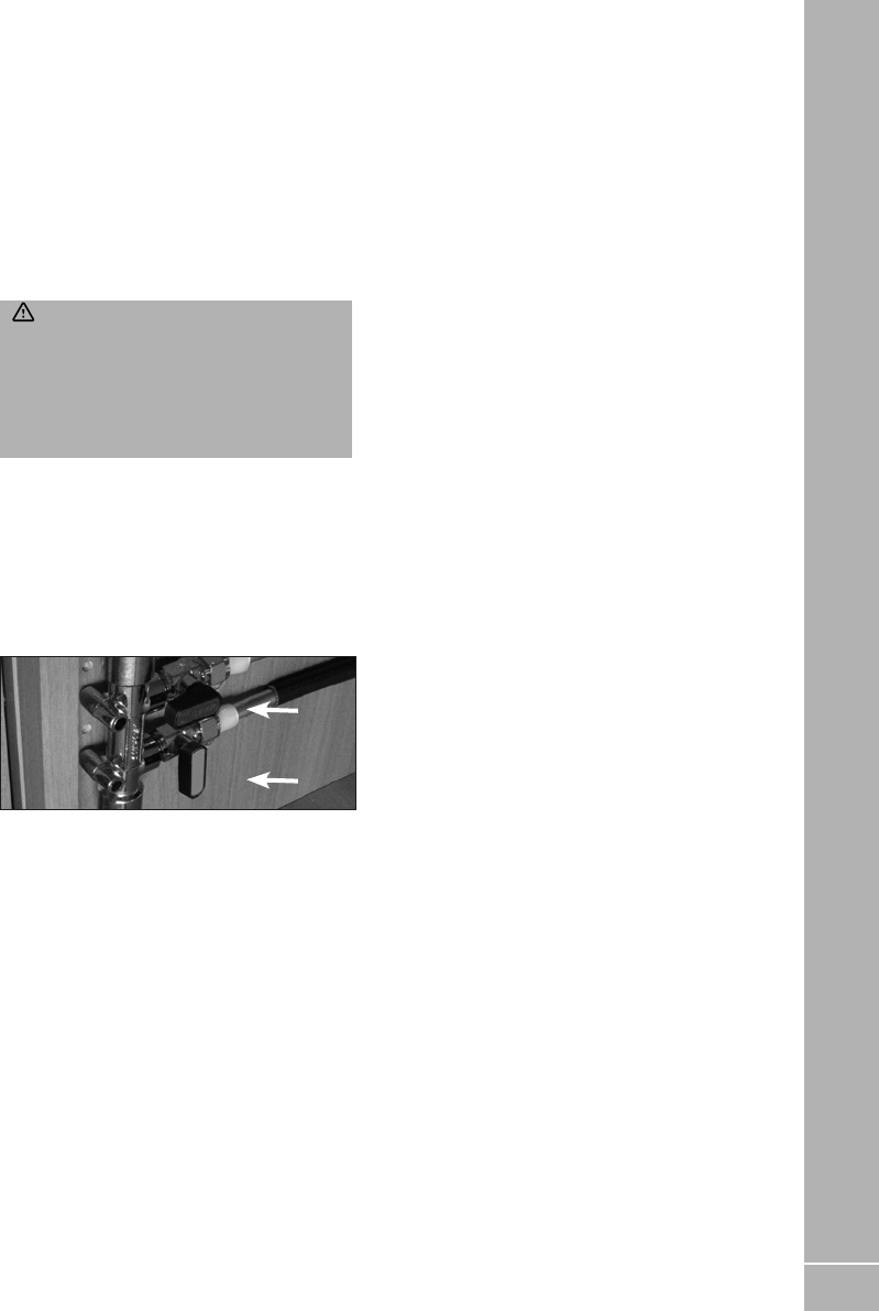
63
Connection
Ensure that the gas regulator hose is correctly
connected to the gas cylinder in gas bottle
compartment and that the hose connection is
tight.
Gas cylinders must be fully located, seated at
the base of the bottles and restrained by the
straps provided in the dedicated compartment
position. Straps are positioned to suit 6kg, 7kg
and 13kg bottles.
WARNING: If using cylinders other
than those recommended, the user must
ensure these are adequately supported,
ventilation openings must not be obstructed
and the cylinders must not cause damage
to other fixtures and fittings located in the
compartment.
Open ended gas hoses must always be
protected from dirt and insects.
Before turning on the gas supply at the
regulator, ensure that all gas operated
equipment in the motorhome is turned off.
All gas equipment is supplied through a Gas
Manifold System which has individual isolation
taps for each appliance (Fig A), as follows:
Fig. A
ON
OFF
YELLOW - Hob
GREEN - Oven / Grill
BLUE - Fridge
RED - Water Heater
WHITE - Heater / Combination Boiler
Flue installations
All flue installations should be inspected once a
year throughout their length for corrosion. Flues
should be replaced if any sign of perforation
is found. Ensure that the replacement is of an
approved type.
Thermal insulation heating
Your motorhome has been designed to achieve a
thermal insulation and heating level for specific
climatic conditions when tested according to the
procedure in EN1646-1.
See the motorhome technical book for the
classification of your motorhome. All Swift
Group motorhomes achieve a Grade 3
classification.
The classifications are as follows:
Grade 1
A motorhome with an average thermal
transmittance (u) that does not exceed 1.7w/
(m2k).
Grade 2
A motorhome with an average thermal
transmittance (u) that does not exceed 1.7w/
(m2k) and which can achieve an average
temperature difference of at least 20°C between
inside and outside temperatures when the
outside temperature is 0°C.
Grade 3
A motorhome with an average thermal
transmittance (u) that does not exceed 1.2w/
(m2k) and which can achieve an average
temperature difference of at least 35°C between
inside and outside temperatures when the
outside temperature is -15°C.
SERVICES

64
SERVICES
Fault Cause Remedy
Hob does not light No gas
Air in pipe
Check level of gas in cylinder
Check gas cylinder valve is on
Check gas taps are on
Purge system
Refer to hob manufacturers instructions
Oven does not light No gas
Air in pipe
Check level of gas in cylinder
Check gas cylinder valve is on
Check gas taps are on
Purge system
Refer to oven manufacturers instructions
BBQ does not light No gas
Over gassed
Air in pipe
Check level of gas in cylinder
Check gas cylinder valve is on
Check gas taps are on
Turn off appliance, wait 2 minutes and try
again
Purge system
Fridge does not light No gas
Air in pipe
Check level of gas in cylinder
Check gas cylinder valve is on
Check gas taps are on
Purge system
Refer to fridge manufacturers instructions
Combination Heater
does not light
No gas
Air in pipe
Check level of gas in cylinder
Check gas cylinder valve is on
Check gas taps are on
Purge system
Refer to water heater manufacturers
instructions
7.14 Gas fault finding
SERVICES

65
7.15 The electrical system
General Information
It is strongly advised that the mains installation
is inspected periodically to ensure safe use. The
IET (BS7671) wiring regulations recommend
that mains installations in motorhomes are re-
inspected every 3 years or annually if the van is
used frequently. The National Caravan Council
lists the qualifications necessary to perform this
inspection, but an NICEIC approved contractor is
probably the first choice.
On arrival at the campsite
• Check the suitability of the supply, is it AC or
DC, is the voltage and frequency correct.
• Ensure that there is a proper earth (3 pin
socket outlet).
• If in doubt consult site staff.
• Make sure that the supply from the site is
switched off.
• Make sure that the charger switch on the PSU
is switched off.
• Lift the cover on the electricity inlet on the
motorhome, and insert the connector on the
flexible supply cable.
• At the site supply point, connect the other end
of the supply cable to this using the socket
provided.
• Switch on the main switch at the site supply
point.
iNote: It is good practice to test the RCD
(Residual Current Device) in the PSU before
switching on. There is a test button on the
RCD. To test the lever, put the lever in the up
position (on) before testing.
iNote: As with the RCD it is good practice
to check the Miniture Circuit Breaker (MCB)
in the PSU. Switch all to the on position (lever
up). If any do not stay up then there is a fault.
On departure from the campsite
• Switch off supply from the site, disconnect the
cable at both ends.
• Switch off RCD.
iNote: Never use a mains supply lead whilst
coiled. Always uncoil the full length before
connecting to the supply and remember to
protect the cable from traffic.
WARNING: Current consumption in the
motorhome must not exceed 16 amps or the
pitch permitted maximum if this is less than
16 amps.
Overseas connection
• Connection to a mains voltage overseas
requires particular attention.
• Overseas supplies can be of reverse polarity.
• Reverse polarity results in equipment not
necessarily being isolated when turned off,
reverse polarity indicator on the PSU will light
in the event of reverse polarity.
• The only sure way to make equipment safe is
to unplug it.
• It is useful to have a means of checking polarity
when overseas.
• If it can be achieved then connect live to live,
and neutral to neutral to achieve full electrical
protection.
WARNING: Never allow modifications
or repairs of electrical or LPG systems and
appliances except by qualified persons.
SERVICES

66
7.16 230V mains electrical equipment
power consumption
Please note: It is possible that the 230v mains
electrical equipment may not all operate
simultaneously. A typical UK site mains hook up
point provides a maximum output of 10 amps
and on some continental sites the available
output may be as low as 5 amps. If your loading
exceeds the site supply it may trip the site circuit
breaker. Please check the available mains
supply with your site operator.
Similarly loadings on each circuit breaker
within the motorhome should be observed. A
label positioned close to the MCB’s (Miniture
Circuit Breakers will identify which appliances
within the motorhome are fed from which MCB.
Consulting the typical appliance consumption
figures table in conjunction with this label, will
give an indication of which appliances can, and
cannot, (site supply allowing), be operated
simultaneously.
SERVICES
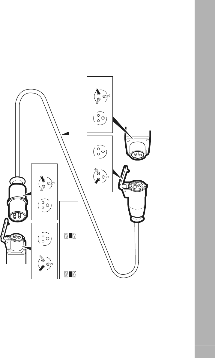
67
SERVICES
SERVICES
PITCH SUPPLY
OUTLET
CABLE COUPLER
MOTORHOME MAINS INLET
VIEW OF
FLEXIBLE 3 CORE CABLE 2.5mm
2
TERMINALS
FLEXIBLE WIRING FIXED WIRING
VIEW OF VIEW OF
SOCKET TUBES PINS
VIEW OF
TERMINALS
BLACK
NEUTRAL
EARTH
GREEN &YELLOW
NEUTRAL BLUE
LIVE BROWN
NEUTRAL BLACK
EARTH GREEN & YELLOW
LIVE RED
RED
LIVE
EARTH GREEN & YELLOW
LIVE
LIVE
EARTH EARTH
BROWN
LIVE
BLUE
NEUTRAL
EARTH
YELLOW & GREEN
NEUTRAL NEUTRAL
VIEW OF
TERMINALS
VIEW OF VIEW OF
SOCKET TUBES
VIEW OF
PINS TERMINALS
BLUE
NEUTRAL
EARTH
BROWN
GREEN &YELLOW
LIVE
LIVE
LIVE
EARTH
BROWN
EARTH
LIVE
BLUE
NEUTRAL
EARTH
YELLOW & GREEN
NEUTRAL NEUTRAL
Wiring of connecting cable and motorhome mains inlet
The legal length of the mains inlet cable is 25 ± 2 metres. When in use it must be fully uncoiled and protected from traffic.
7.17 Wiring of connecting cable and motorhome mains inlet

68
7.18 Typical appliance consumption figures
SERVICES
23 0 Vo lt 12 Vol t LP G as
Appliance/ Item Watts Amperes Watts Amperes grams/hour
Dometic Refrigerator 190 W 0.8 amp Only when driving 16 g/h
Truma Combi 4kw Heating System
900 / 1800 W 3.9 / 7.8 amp 13 w 1.1 amp (avg) 320 g/h
Truma Combi 6kw Heating System
900 / 1800 W 3.9 / 7.8 amp 13 w Up to 6.5 amps 480 g/h
Alde Heating System
1050 / 2100 / 3150 W 4.6 / 9.1 / 13.7 amp Up to 23w Up to 1.9 amps 245 - 460 g/h
Microwave (Factory fit) Up to 1270w Up to 5.5 amp Not Applicable
Not Applicable
Cooker - Hob burners Not applicable Not applicable 70 – 161 g/h each
Cooker – Electric Hotplate 800 w 3.5 amp Not applicable Not applicable
Grill Not applicable
0 - 14.4w
(Cooling fan)
0 - 1.2amp
(Cooling fan)
117 g/h
Oven Not applicable
0 - 14.4w
(Cooling fan)
0 - 1.2amp
(Cooling fan)
125 – 146 g/h
Battery Charger
690 W 3.0 amp Not applicable Not applicable
Omnivent Not applicable
2 w – 3 0 w
0.2 amp – 2.5 amp Not applicable
Powered bed mechanism Not applicable
M a x 2 4 0 w
Max 20amp Not applicable
Powered table mechanism Not applicable
U p t o 6 3 w
Up to 5amps Not applicable
12v LED lights (each, depending in size of light) Not applicable
0 . 4 w - 6 . 1 w
0.05 amp – 0.5 amp Not applicable
USB socket or USB charging socket within light Not applicable
U p t o 1 8 w
Up to 1.5 amps Not applicable
Water tank frost element (Winter pack) Not applicable
3 0 W
2.5 amp each Not applicable
Note: These are approximate figures for guidance only, and are subject to changes in specification. The figures show energy consumption when an item or
a
ppliance is operating – i.e. a light is illuminated, or a heating system is providing space heating or water heating. Appliances which feature LCD or
i
lluminated control panels can have a low current consumption when in stand by mode, or have a constant low current draw in the background to run their
d
isplays and electronic systems - these figures are typically 0.4 amps or less, for each applicable item. These electronic items can in most cases be switched
off individually, or, use of the System Shutdown button on the power supply unit isolates all of these items.

69
ELECTRICS
8. Electrics
8.1
EC400+ Motorhome Power Control System (Edge, Ascari, Voyager and Escape)
. . 70
8.2 Using the System . . . . . . . . . . . . . . . . . . . . . . . . . . . . . . . . . . . . . . . . . . . . . . . . . . . . . . . 71
8.3 EC400 + Control Panel Component Layout . . . . . . . . . . . . . . . . . . . . . . . . . . . . . . . 72
8.4 System Warnings . . . . . . . . . . . . . . . . . . . . . . . . . . . . . . . . . . . . . . . . . . . . . . . . . . . . . . . 74
8.5 Water System Operation . . . . . . . . . . . . . . . . . . . . . . . . . . . . . . . . . . . . . . . . . . . . . . . . 75
8.6 Frost Protection Operation (where fitted) . . . . . . . . . . . . . . . . . . . . . . . . . . . . . . . . 75
8.7 Solar Charge Management (where fitted) . . . . . . . . . . . . . . . . . . . . . . . . . . . . . . . 75
8.8 Smart Charging . . . . . . . . . . . . . . . . . . . . . . . . . . . . . . . . . . . . . . . . . . . . . . . . . . . . . . . . . 76
8.9 Electric Step Operation (where fitted) . . . . . . . . . . . . . . . . . . . . . . . . . . . . . . . . . . . 76
8.10 System Technical Information . . . . . . . . . . . . . . . . . . . . . . . . . . . . . . . . . . . . . . . . . . 77
8.11 Generator Usage . . . . . . . . . . . . . . . . . . . . . . . . . . . . . . . . . . . . . . . . . . . . . . . . . . . . . . 78
8.12 Battery Charger . . . . . . . . . . . . . . . . . . . . . . . . . . . . . . . . . . . . . . . . . . . . . . . . . . . . . . . 78
8.13 Leisure Battery . . . . . . . . . . . . . . . . . . . . . . . . . . . . . . . . . . . . . . . . . . . . . . . . . . . . . . . . 79
8.14 12 Volt DC Fuses . . . . . . . . . . . . . . . . . . . . . . . . . . . . . . . . . . . . . . . . . . . . . . . . . . . . . . . 81
8.15 Common Fault Table . . . . . . . . . . . . . . . . . . . . . . . . . . . . . . . . . . . . . . . . . . . . . . . . . . . 82
8.16 Contact details . . . . . . . . . . . . . . . . . . . . . . . . . . . . . . . . . . . . . . . . . . . . . . . . . . . . . . . . 84
8.17 Technical Data . . . . . . . . . . . . . . . . . . . . . . . . . . . . . . . . . . . . . . . . . . . . . . . . . . . . . . . . 85
8.18 Approvals . . . . . . . . . . . . . . . . . . . . . . . . . . . . . . . . . . . . . . . . . . . . . . . . . . . . . . . . . . . . . 86
8.19 Declaration of Conformity . . . . . . . . . . . . . . . . . . . . . . . . . . . . . . . . . . . . . . . . . . . . . . 86
8.20 Swift Command Power Control System (Kon-Tiki) . . . . . . . . . . . . . . . . . . . . . . . . . . 87
8.21 Control System Operation . . . . . . . . . . . . . . . . . . . . . . . . . . . . . . . . . . . . . . . . . . . . . . 88
8.22 EC800 Control Panel . . . . . . . . . . . . . . . . . . . . . . . . . . . . . . . . . . . . . . . . . . . . . . . . . . . 89
8.23 System Warnings . . . . . . . . . . . . . . . . . . . . . . . . . . . . . . . . . . . . . . . . . . . . . . . . . . . . . . 99
8.24 System Technical Information . . . . . . . . . . . . . . . . . . . . . . . . . . . . . . . . . . . . . . . . . 101
8.25 Common Fault Table . . . . . . . . . . . . . . . . . . . . . . . . . . . . . . . . . . . . . . . . . . . . . . . . . . 105
8.26 Remote Access & Control . . . . . . . . . . . . . . . . . . . . . . . . . . . . . . . . . . . . . . . . . . . . . 108
8.27 Technical Data & Approvals . . . . . . . . . . . . . . . . . . . . . . . . . . . . . . . . . . . . . . . . . . . 109
8.28 Motorhome battery . . . . . . . . . . . . . . . . . . . . . . . . . . . . . . . . . . . . . . . . . . . . . . . . . . . 111
8.29 Solar panel connection point or Solar panel fitment . . . . . . . . . . . . . . . . . . . . 115
8.30 Accessory harnessing . . . . . . . . . . . . . . . . . . . . . . . . . . . . . . . . . . . . . . . . . . . . . . . . 116
8.31 Generator usage . . . . . . . . . . . . . . . . . . . . . . . . . . . . . . . . . . . . . . . . . . . . . . . . . . . . . 117
8.32 Habitation relay . . . . . . . . . . . . . . . . . . . . . . . . . . . . . . . . . . . . . . . . . . . . . . . . . . . . . . 117
8.33 Fault Finding . . . . . . . . . . . . . . . . . . . . . . . . . . . . . . . . . . . . . . . . . . . . . . . . . . . . . . . . . 118

70
8.1 EC400+ Motorhome Power
Control System (Edge, Ascari,
Voyager and Escape)
1. Introduction
This section of the handbook will guide you
through the operation of the electrical system.
All details are correct at the time of going to
press. Please also see the online version which
will include any later updates or amendments.
Further technical details are contained in
section 3 or in the supporting technical manual
available from www.sargentltd.co.uk
For the safe operation of all electrical equipment
within your Leisure Vehicle it is important
that you read and fully understand these
instructions. If you are unsure of any point,
please contact your dealer / distributor for
advice before use.
The system has a number of key components
that you will need to be familiar with before
attempting to use the system, these are:
• The EC454PSU or EC456PSU Power Supply
Unit - a combined mains consumer unit and
12V controller usually located in a storage area
(lower bed box, wardrobe or similar).
• The EC463 Control Panel - a remotely located
user control panel used to turn circuits on and
off and to display battery, water tank and other
system information.
• The PX300 Intelligent 300W Battery charger.
ELECTRICS

71
8.2 Using the System
Power Supply Unit - Component Layout (see
image on previous page)
The PSU is located in the front offside bed box
area.
Activating the System
The system has a shutdown feature that can be
used when the vehicle is in storage. This allows
the leisure electronics to be turned off when not
required to save battery power. When in the off
state the alarm and tracking system supplies are
still active, all other supplies are turned off.
Before using the system, please ensure the
system shutdown switch is in the on position
(button in) the system is now active.
Connecting to the Mains 230V supply and
Safety checks
For your safety it is IMPORTANT that you follow
these connections instructions each time
your Leisure Vehicle is connected to a mains
supply. This section assumes that the system
is complete and that a Leisure battery has been
installed (see 3.4).
A) Ensure suitability of the Mains Supply.
Your Leisure Vehicle should only be connected
to an approved supply that meets the
requirements of BS7671 or relevant harmonised
standards. In most cases the site warden will
hold information regarding suitability of supply.
If using a generator, you also need to comply
with the requirements / instructions supplied
with the generator. Please note that some
electronic generators may not be compatible
with your leisure system. Further generator
operational information is contained in section
3.2.
B) Switch the PSU Battery Charger / Power
Converter OFF.
Locate the green ‘Charger’ power switch on the
PSU and ensure the switch is in the off position
(button out) before connection to the mains
supply.
C) Connect the Hook-up Lead.
Firstly, connect the supplied hook-up lead
(orange cable with blue connectors) to the
Leisure Vehicle and then connect to the mains
supply.
D) Check Residual Current Device operation.
Locate the RCD within the PSU and ensure the
RCD is switched on (lever in up position). Press
the ‘Test’ button and confirm that the RCD turns
off (lever in down position). Switch the RCD
back to the on position (lever in up position). If
the test button failed to operate the RCD see
section 3.1.
E) Check Miniature Circuit Breakers
Locate the MCB’s within the PSU (adjacent to
the RCD) and ensure they are all in the on (up)
position. If any MCB’s fail to ‘latch’ in the on
position see section 3.1.
F) Turn the PSU ON.
Locate the black ‘Shutdown’ button and ensure
it is in the on position (press button in). Locate
the green ‘Charger’ switch on the PSU and turn
to the on position (press button in). The charger
switch will illuminate when turned on.
G) Check correct Polarity.
Locate the ‘Reverse polarity’ indicator on
the PSU and ensure that the indicator is NOT
illuminated. If the indicator is illuminated see
section 3.2.
H) Check operation of equipment.
It is now safe to operate the 12V and 230V
equipment.
Operation while driving
The power control system is designed to
shutdown parts of the system while the engine
is running. This is to meet Electro Magnetic
Compatibility (EMC) regulations and to ensure
the safe operation of the motorhome. With
the engine running the control panel will flash
the leisure battery and vehicle battery LEDs to
indicate that the batteries are being charged.
Please ensure the system shutdown switch
on the PSU is in the on (button in) position
before driving (see 2.2). This will ensure the
electronic system is active and will therefore be
able to control the charging process, supply the
refrigerator and monitor other system circuits.
If / when fitted, designated 12V sockets, en-
route reading lights and en-route heating will
remain operational while the engine is running.
ELECTRICS

72
8.3 EC400 + Control Panel Component
Layout
Your control panel will have an appearance as
below, but depending on your specification of
the vehicle the control panel features will vary.
Not all features are present in all vehicles.
Power Button. Press the power button to turn the leisure power on. Press
the button again to turn the power off. The adjacent indicator will illuminate
when the power is on, and also the voltage of the selected battery will be
displayed on the voltage gauge.
Pump Button. With the power on, press the pump button to turn the water
pump on. Press the button again to turn the pump off. The adjacent indicator
will illuminate when the pump is on, and also the level of the water tank will
be displayed on the water gauge (if a tank with level sensor is fitted)
View Levels Button. To display the battery voltage levels and the water tank
levels on the control panel gauges, press the levels button. The display
will remain illuminated for 10 seconds. It is possible to lock the display ‘on’
to allow continuous display. This can be achieved by pressing and holding
the view levels button for 2-3 seconds until you hear a beep. To turn this
locked feature off, either press and hold the view levels button again for 2-3
seconds or turn the power off and back on.
Leisure Battery Button. To select the Leisure battery as the source of power,
press the leisure battery select button. The Leisure battery indicator with
then illuminate, confirming the selected battery. Note: By default, the leisure
battery is selected as the source of power (if no mains supply is available), or
as the battery to be charged (when a mains supply is available).
Control Panel - Key Features
EC463 Control Panel
ELECTRICS

73
Further information relating to the control panel features can be found in the following sections.
Vehicle Battery Button. To select the Vehicle battery as the source of power,
press the vehicle battery select button. The Vehicle battery indicator with then
illuminate, confirming the selected battery.
Mains On Indicator. When connected to a 230V supply and the battery charger
is turned on this indicator will illuminate.
Charging when the vehicle engine is running. When the vehicle engine is
running both the vehicle battery and the leisure battery indicators will flash in
unison to indicate that they are connected together and are being charged by
the vehicle.
Internal Lights Button. With the power on, press the internal lights button to
turn the main lighting supply on or off.
Awning Light Button. With the power on, press the awning light button to turn
the awning light on or off.
Frost Protection Button (if fitted). With the power on, press the frost protect
button to turn on the water tank heating system. The adjacent indicator will
illuminate to show that the tank heating system is on.
ELECTRICS

74
Warning When Type
Fresh water
level low
With pump turned on and fresh
water level low (less than 25% full)
Only available when an on-board
tank is fitted
Audible beep and the Fresh gauge empty
indicator will flash
(To cancel press Levels Button)
Waste water
level full
With pump turned on and waste
water level full.
Only available when an on-board
tank is fitted
Audible beep and the Waste gauge empty
indicator will flash
(To cancel press Levels Button)
Leisure battery
voltage low
With control panel power on and
leisure battery selected (as active
battery) and the voltage level falls
below 10V
Audible beep and the Leisure battery
gauge 10V indicator will flash
(To cancel press Levels Button)
With control panel power on and
leisure battery selected (as active
battery) and the voltage level is
below 9V
Audible beep and Leisure battery gauge
10V indicator will flash. If the warning is
not cancelled the control panel will be
turned off.
(To cancel press Levels Button)
Note: This is an emergency cut off level to protect the battery from severe
damage. You should not rely on this cut off level during normal operation, but
manage your power consumption to a discharge level of 11.5V or above.
This cut off only applies to power drawn from the battery by the leisure
equipment that is controlled by the control panel power switch; it will not
protect the battery from discharge by permanently connected equipment.
Leisure battery
voltage high
With control panel power on or off
and leisure battery is selected (as
active battery) and the voltage
level rises above 15V
Audible beep, the Leisure battery gauge
14V indicator will flash, and the control
panel power will be turned off.
(To cancel remove the high voltage
source)
8.4 System Warnings
The system incorporates a number of warnings that are active at specific times. These are
summarised below, and also covered by relevant sections of this manual.
When a warning is active a warning box will appear on the control panel screen containing a
description of the warning along with an audible beeping sound.
ELECTRICS

75
Warning When Type
Vehicle battery
warnings
If the vehicle battery is selected instead of the leisure battery, then similar
warnings to those described above are applied to the vehicle battery. The
vehicle battery low warning level is 10.9V
Vehicle battery
warnings
If the vehicle battery is selected instead of the leisure battery, then similar
warnings to those described above are applied to the vehicle battery. The
vehicle battery low warning level is 10.9V
Engine running
When the engine is started the system power will be turned off
Engine running,
Step extended
Step extended and engine started Short warning beeps before the step is
automatically retracted
Step jammed or obstructed Continuous warning beeps
Engine running,
Mains lead
(hook-up
cable) still
connected /
plugged in
When the engine is started and the
mains cable is still plugged in and
the charger is switched on
Continuous warning beeps
8.5 Water System Operation
The control panel pump button operates the
internal (onboard) water pump.
The system also incorporates a separate
powered water inlet that can be used with an
external filler pump to fill the internal (onboard)
water tank.
The water tanks (fresh & waste) incorporate a
level warning feature to warn the user when the
fresh water level drops below 25% or when the
waste water level reaches 100%.
If the water pump power is turned on and the
fresh water level drops to below 25% a warning
beep will be heard and the fresh gauge empty
indicator will flash. To cancel the warning, press
the levels button.
If the water pump power is turned on and the
waste water level rises to full (100%) a warning
beep will be heard and the waste gauge full
indicator will flash. To cancel the warning, press
the levels button.
These warnings will not be repeated unless the
water pump power switch is turned off and on
again. This is to ensure the warning does not
become a nuisance.
8.6 Frost Protection Operation
(where fitted)
On vehicles fitted with water tank frost
protection, the control panel frost protect switch
can be used to turn the feature on or off.
With protection on, the system monitors the
external temperature and will control the tank
heaters accordingly. The heaters will switch on
at 4-5 Deg C and off at 8-10 Deg C. If the fresh
or waste water levels are less than 25% the
appropriate heater will be turned off to prevent
overheating or damage to the element.
8.7 Solar Charge Management
(where fitted)
The Power Supply Unit incorporates a built-in
solar charge management feature, which will
control the input from a separate solar panel and
regulator. Depending on the charge state of the
batteries, the solar power will be directed to the
required battery, and continuously monitored
to ensure optimum operation. For this system
to operate intelligently, the shutdown button
should be left switched on. If the shutdown
button is turned off then the solar panel will
charge the vehicle battery only.
ELECTRICS

76
8.8 Smart Charging
The Power Supply Unit incorporates a smart
charge feature, which monitors both leisure and
vehicle batteries and automatically adjusts and
directs the charger power (and solar power if a
solar panel is installed) to maintain the leisure
and vehicle batteries at an optimal level.
iNote: If the vehicle battery is isolated using
the Fiat ignition key isolator or similar, some
smart charging functionality will be lost, and
the available charge will be directed to the
leisure battery.
8.9 Electric Step Operation (where
fitted)
On vehicles fitted with an electric step, this is
operated by a button near the entry door. Press
and release the button to move the step in or
out. One press of the button will move the step
out; a further press will move the step in again.
If the engine is started the step will move in
automatically, after a short warning buzzer. If
this operation fails due to an obstacle a buzzer
will sound continuously to warn that the step is
still out, and therefore requires your attention.
ELECTRICS

77
MCB Rating Output Wire Colour Description
1 10 Amps White 230V Sockets
2 16 Amps White (Yellow for heater) Extra 230V Sockets / Heating System
3 10 Amps Black (Blue for Whale
water heater)
Fridge / Charger / Auxiliary devices / Whale
Water Heater
8.10 System Technical Information
The following section provides further technical
information relating to the electrical system.
You can also access the supporting technical
manual from www.sargentltd.co.uk
Residual Current Device & Miniature Circuit
Breakers
The Residual Current Device (RCD) is basically
provided to protect the user from lethal electric
shock. The RCD will turn off (trip) if the current
flowing in the live conductor does not fully
return down the neutral conductor, i.e. some
current is passing through a person down to
earth or through a faulty appliance.
To ensure the RCD is working correctly, the test
button should be operated each time the vehicle
is connected to the mains supply (see section
2.3)
The Miniature Circuit Breakers
(MCB’s) operate in a similar way to traditional
fuses and are provided to protect the wiring
installation from overload or short circuit. If
an overload occurs the MCB will switch off the
supply. If this occurs you should investigate
the cause of the fault before switching the MCB
back on.
The following table shows the rating and circuit allocation for the three MCB’s
ELECTRICS

78
8.11 Generator Usage
Caution should be used before connecting a
generator to your motorhome.
WARNING: Never start or stop the
generator while electrical loads are connected
and switched on. Start the engine, let it
stabilise and then connect the electrical load.
When stopping the generator, disconnect the
electrical load and let engine stabilise before
switching off.
Whilst some generators use electronic inverter
technology, others use a more basic principle to
generate the 230V supply. Preference should
be to choose a generator which produces a
consistent sinusoidal wave form with accurate
voltage control.
The Reverse Polarity warning light on the PSU
may illuminate when using a Generator. This is
a normal side effect when using some types of
generator. Instead of connecting the neutral
conductor to earth, some generators centre-tap
the earth connection making both neutral and
live conductors 110V above earth. This 110V
difference causes the neon polarity indicator to
illuminate.
In most cases it is safe to use a generator, but
please consult the generator handbook for
further information.
8.12 Battery Charger
The system incorporates an intelligent three-
stage battery charger.
During stage 1 the battery voltage is increased
gradually while the current is limited to start the
charging process and protect the battery. At
stage 2 the voltage rises to 14.4V to deliver the
bulk charge to the battery. When the battery
is charged, the voltage is decreased at stage
3 to 13.6V to deliver a float charge to maintain
the battery in the fully charged state. The
charger can be left switched on continuously as
required.
The battery charger / power converter also
provides power to the leisure equipment when
the mains supply is connected. This module
supplies DC to the leisure equipment up to a
maximum of 25 Amps (300 Watts), therefore
the available power is distributed between the
leisure load and the battery, with the leisure load
taking priority as per the following example:
Leisure
Load
Available power for battery
charging
5A 20A
10A 15A
15A 10A
20A 5A
WARNING: Under heavy loads the Battery
Charger case may become hot. ALWAYS
ensure the ventilation slots have a clear flow of
air. Do not place combustible materials against
/ adjacent to the charger.
ELECTRICS

79
8.13 Leisure Battery
A) Type / Selection
For optimum performance and safety, it is
essential that only a proprietary brand LEISURE
battery is used and it is suggested to select a
battery from the NCC Verified Battery Scheme
with a typical capacity of 75 to 120 Ah
(Ampere / hours). Depending on the
prospective use of the vehicle, the correct type
should be selected (A, B or C, according to the
NCC Verified Battery Scheme). A normal car
battery is NOT suitable. This battery should
always be connected when the system is in use.
The PSU is configured to work with standard
lead acid leisure batteries, and in most cases
is also compatible with the latest range of
Absorbed Glass Matt (AGM) batteries. The
system is also suitable for Lithium batteries with
built-in Battery Management Systems BMS.
Before fitting non-standard batteries, please
check that the charging profile described in 3.3
is suitable for the type of battery by referring
to the battery documentation or battery
manufacturer.
Some vehicle installations can cater for two
leisure batteries connected in parallel. In these
cases, it is recommended that two identical
batteries are used.
The battery feed is fitted with an inline fuse
between the battery and the electrical harness,
and is usually located immediately outside the
battery compartment or within 500mm of the
battery. The maximum rating of this fuse is 40A
per battery.
B) Installation & Removal
Always disconnect the 230V mains supply
and turn the PSU green charger switch to the
off position (button out) before removing or
installing the battery.
When connecting the battery, ensure that the
correct polarity is observed (black is negative
[-] and red is positive [+]) and that the terminals
are securely fastened. Crocodile clips must not
be used.
WARNING: Explosive gases may be
present at the battery. Take care to prevent
flames and sparks in the vicinity of the battery
and do not smoke.
C) Operation / Servicing
Under normal circumstances it should not be
necessary to remove the battery other than for
routine inspection of the terminals and “topping
up” of the battery fluid where applicable. Please
see instructions supplied with the battery.
iNote: Do not over discharge the battery.
One of the most common causes of battery
failure is when the battery is discharged below
the recommended level of approximately 10V.
Discharging a battery below this figure can
cause permanent damage to one or more of
the cells within the battery.
To prevent over discharge, the power control
system incorporates a battery protect circuit
that warns the users and then disconnects the
batteries when they fall below set values.
If a warning is active a beep will be emitted by
the control panel. To cancel the warning, press
the Levels Button. These warnings will not be
repeated unless the power switch is turned off
and on again. This is to ensure the warning does
not become a nuisance.
ELECTRICS

80
Battery Voltage
cut off
Action after
cut off
Notes
Vehicle 10.9V Battery selection is
changed from Vehicle
battery to Leisure
battery. If the leisure
battery is below 9V then
a further warning will
occur (see below).
This cut off level is designed to protect the
vehicle battery from over discharge. The
10.9V level ensures there is sufficient power in
the battery to run the vehicle electronics and
start the vehicle. This cut off only applies to
power drawn from the battery by the leisure
equipment; it will not protect the battery if you
leave vehicle circuits switched on, such as the
road lights.
Leisure 9V Power is turned off This is an emergency cut off level to protect
the battery from severe damage. You
should not rely on this cut off level during
normal operation, but manage your power
consumption to a discharge level of about
11.5V.
This cut off only applies to power drawn from
the battery by the leisure equipment that is
controlled by the control panel power switch;
it will not protect the battery from discharge
by permanently connected equipment.
ELECTRICS

81
Fuse Rating Fuse
Colour
Description
Battery 1 40 Amps Orange Fuse remotely located near battery
Battery 2 40 Amps Orange Fuse remotely located near battery 2 (where fitted)
8.14 12 Volt DC Fuses
WARNING: When replacing fuses always replace a fuse with the correct value. NEVER replace
with a higher value / rating as this could damage the wiring harness. If a replacement fuse ‘blows’
do not keep replacing the fuse as you could damage the wiring harness. Please investigate the
fault and contact your dealer.
Fuse Rating Fuse Colour Description
1 25 Amps White Battery Charger
2 7.5 Amps Brown Fridge Controls / Alarm
3 10 Amps Red 12V & USB Sockets / TV Amp
4 10 Amps Red Extractor, Cooker hood, Heki powered skylight. Alde or Truma
Combi Heating (Not En-Route), Whale Water Heater
5 10 Amps Red Appliances, Cooker, Toilet, Whale Space Heater, Locker
Mount USB, Tank Valves
6 10 Amps Red Water Pumps / Tank Heaters
7 7.5 Amps Brown Main lighting (not including spotlights with USB), Rear
ambient lighting, Offside awning light
8 7.5 Amps Brown Entry lights, Front ambient lighting
9 10 Amps Red Alde or Truma En-Route Heating, Marker Lights, En-Route
lighting, 12V Sockets, WiFi & Satellite supply
10 10 Amps Red Awning Light (Doorside) / Electric Step
11 15 Amps /
20 Amps
Blue/Yellow Fridge 12V: 15A for undercounter fridge, 20A for tall fridge
freezer
12 15 Amps Blue Towing 12V
13 15 Amps /
20 Amps
Blue/Yellow Fridge D+: 15A for undercounter fridge, 20A for tall fridge
freezer
The following table shows the fuse allocation for the 13 fuses fitted to the PSU. Please note that fuses
are dependant on PSU versions, so not all fuses may be present.
iNote: Fuses (2-13) have a Red LED below them which provides indication that the fuse has
blown. The charger fuse has a green LED which Indicates that the charger is working.
ELECTRICS

82
Fault Possible Cause Proposed Fix
No 230 Volt
output from
PSU
Connecting lead between the site
and Leisure Vehicle not connected
Check and connect lead as per 2.3C
RCD switched off Reset RCD as per 2.3D
RCD not operating correctly Check supply polarity; if the RCD
continues to fail contact your Dealer as
there is probably an equipment or wiring
fault.
MCB switched off Reset MCB by switching OFF (down
position) then back ON (up position), if
the MCB continues to fail contact your
Dealer as there is probably an equipment
or wiring fault.
No or deficient supply from site Contact site Warden for assistance.
Another fault Contact your Dealer
Reverse
Polarity light is
illuminated on
PSU
Mains Supply reversed? The reverse polarity light is designed
to illuminate when the Live and Neutral
supply has been reversed / crossed
over. If the light illuminates there is a
problem with the site supply or the cable
connecting the supply to your vehicle. The
light is designed to work on UK electrical
supplies (where the neutral conductor
is connected to earth at the substation).
If you are using your vehicle outside the
UK this light may illuminate when no fault
exists. In these cases, consult the site
warden for advice.
Generator being used ‘The Reverse Polarity warning light is on
when using my Generator’.
This is a normal side effect when using
some types of generator. Instead of
connecting the neutral conductor to
earth, some generators centre-tap the
earth connection making both neutral and
live conductors 110V above earth. This
110V difference causes the neon polarity
indicator to illuminate. In most cases it is
still safe to use the generator, but please
consult the generator handbook for
further information.
8.15 Common Fault Table
ELECTRICS

83
Fault Possible Cause Proposed Fix
Control Panel
Problems
Control Panel has no display Check batteries and fuses, turn PSU
isolate switch and charger switch on and
ensure mains supply is connected.
Check control panel connecting lead at
PSU and behind Control Panel.
Contact your Dealer.
12V Power turns off Battery protect feature has operated to
protect the Vehicle battery and or the
Leisure battery. See 3.4C
Over voltage protection has been
activated, control panel is beeping, 14V
LED is flashing (leisure or vehicle). A
number of things can cause this but
the most common is the solar panel,
it is worth checking the regulator is
connected correctly and operating within
the correct parameters.
Engine has been started; all equipment
has been disconnected to meet EMC
requirements. See 2.4
Control Panel locked / erratic
function
Observe control panel handling
instructions.
Control panel software may have
crashed. Reboot control panel by turning
off the PSU isolate switch. Wait 30
seconds then turn the switch back on.
Check with your dealer that your system
has the latest software installed, as an
update may be available.
No 12 volt
output from
PSU
No 230V supply Check all above
Charger not switched on Turn charger switch on, switch will
illuminate
Battery not connected and / or
charged
Install charged battery as per 3.4
Power button on control panel not
switched to on
Turn power on at control panel
Battery flat / Battery fuse blown Recharge battery, check fuses, check
charging voltage is present at battery.
Fuse blown Check all fuses are intact and the correct
value fuse is installed as per fuse table.
Equipment switched off /
unplugged
Check equipment is switched on and
connected to the 12V supply
Other fault Contact your Dealer
ELECTRICS

84
Fault Possible Cause Proposed Fix
Pump not
working
Fuse blown Replace fuse with correct value as per
fuse table
Pump turned off Turn pump on by pressing the pump
button at the control panel
Lights not
working
Fuse/s blown Replace fuse with correct value as per
fuse table.
Lights turned off Turn Lights on by pressing the lights
button, use dimmer at the control panel.
8.16 Contact details
Sargent Electrical Services Limited provide a
technical help line during office hours. Please
contact 01482 678981 if you require technical
help.
For out of hour support please refer to the
support section of the Sargent web site
www.sargentltd.co.uk
ELECTRICS

85
Outline Specification
Input 230V 230 Volts / 0 to 16 Amps + / - 10%
Output 230V
RCD protected, 2 x MCB outputs of 10A & 1 x MCB
output of 16A
Separate switched channels for heating system and
charger
Input 12V 2 x 20A battery inputs via 2 x 4-way connectors
Solar Input
1 x Dedicated solar panel input capable of supporting
10A of solar power input (typically 180 to 200W) via a
2-way connector
Check the solar panel
rating plate to ensure
the maximum current is
<= 10A
Output 12V
25A total output via multiple switched channels
protected by 13 fused outputs
Battery Charger
Input 220-240 Volts AC +/- 10%, Frequency 50 Hz +/-
6%, Current 3A max.
DC Output 13.6 to 14.4 Volts nominal, Current 25
Amps max (300 Watts).
Signal Input
4 x Fresh water level, 4 x Waste water level, 1 x
Engine running, plus multiple vehicle connections,
sensor inputs for temperature & humidity
Fresh water negative
sensed Waste water
negative sensed
Data In / Out
CANBUS Data communication and power to
Control Panel via 6 way connector CI-Bus Data
communication to CI-Bus enabled devices via
RJ11/12 connector
IP rating IP31
Operating
temperature
Ambient 0 to 35° Celsius Charger case temperature
with full load 65° C Max
Automatic shutdown
and restart if
overheated /overloaded
Dimensions
EC454PSU,
EC456PSU
Power Supply
Unit
Overall size (HxWxD) 180 x 305 x 135mm Clearances
75mm above, 50mm left & right
Weight 3.8 Kg
EC463 Control
Panel
Overall size (HxWxD) 87 x 250 x 15mm Cut-out size
(HxWa) 70 x 233mm
Fixing centres
130*75mm Weight
114 g
8.17 Technical Data
Equipment – EC652, EC653, EC800, EC635 & PX300
ELECTRICS

86
8.18 Approvals
System: BSEN 1648-1, BSEN1648-2 compliant,
BS7671: 2018 compliant
Residual Current Device: RCD 40A 30mA trip to
BS EN 61008
Miniature Circuit Breakers: MCB’s type C 4500A
breaking capacity to BSEN 60898
Electro Magnetic Compatibility (EMC) directive
2014/30/EU Certificate CE20071224-1
Battery Charger: BS EN 60335-2.29
CB, UL60950-1 Approved, IEC61000-4-
2,3,3,4,5,6,8,11, EN55024, Light industry
level, Criteria A, EN55022 (CISPR22) Class B,
EN61000-3-2,3
Low Voltage Directive: 2014/35/EU TUV-
014900-A1
8.19 Declaration of Conformity
Equipment: Leisure Power Control System
Model name: EC454, EC463 CP, EC652, EC643,
EC800 CP & PX300
I hereby declare that the equipment named
above has been designed to comply with the
relevant sections of the above referenced
approvals. The unit complies with all essential
requirements of the Directives.
Signed Name Position Manufacturer
I L Sargent Managing Director Sargent Electrical Services Ltd
Unit 35, Tokenspire Business
Park Woodmansey, Beverley East
Yorkshire, United Kingdom
Date:
25/08/2021
Whilst every effort has been made to ensure the
accuracy and completeness of this document, no
guarantee is given against errors or omissions.
This document may be updated / improved over
time therefore please check with your dealer /
supplier for update information or visit
www.sargentltd.co.uk
ELECTRICS

87
ELECTRICS
8.20 Swift Command Power Control
System (Kon-Tiki)
This section of the handbook will guide you
through the operation of the electrical system.
All details are correct at the time of going to
press. Please also see the online version which
will include any later updates or amendments.
Further technical details are contained in
section 3 or in the supporting technical manual
available from www.sargentltd.co.uk
For the safe operation of all electrical
equipment within your Leisure Vehicle it is
important that you read and fully understand
these instructions. If you are unsure of any
point please contact your dealer / distributor for
advice before use.
The system has a number of key components
that you will need to be familiar with before
attempting to use the system, these are:
• The EC652 or EC653 Power Supply Unit (PSU)
is a combined mains consumer unit and 12V
controller usually located in a storage area
(lower bed box, wardrobe or similar).
• The control panel is used to turn circuits on
and off and to display battery, water tank and
other system information.
• The EC800 control panel uses a graphical
touchscreen.
• The PX300 Intelligent Battery charger 300W.
Fig 1

88
ELECTRICS
8.21 Control System Operation
Power Supply Unit - Component
Layout (see image on previous page)
The PSU is located in the lower bed box,
wardrobe or similar area.
Activating the System
The system has a shutdown feature that can be
used when the vehicle is in storage. This allows
the leisure electronics to be turned off when not
required to save battery power. When in the off
state the alarm and tracking system supplies are
still active, all other supplies are turned off.
Before using the system please ensure the
system shutdown switch is in the on position
(button in) the system is now active.
iNote: if you plan to use the Swift Command
remote features the system needs to be active.
Connecting to the Mains 230V supply
and Safety checks
For your safety it is IMPORTANT that you follow
these connections instructions each time
your Leisure Vehicle is connected to a mains
supply. This section assumes that the system is
complete and that a Leisure battery has been
installed (see 3.4).
A) Ensure suitability of the Mains Supply.
Your Leisure Vehicle should only be connected
to an approved supply that meets the
requirements of BS7671 or relevant harmonised
standards. In most cases the site warden will
hold information regarding suitability of supply.
If using a generator you also need to comply with
the requirements / instructions supplied with
the generator. Please note that some electronic
generators may not be compatible with your
leisure system. Further generator operational
information is contained in section 4.2.
B) Switch the PSU Battery Charger / Power
Converter OFF.
Locate the green ‘Charger’ power switch on the
PSU and ensure the switch is in the off position
(button out) before connection to the mains
supply.
C) Connect the Hook-up Lead.
Firstly connect the supplied hook-up lead
(orange cable with blue connectors) to the
Leisure Vehicle and then connect to the mains
supply.
D) Check Residual Current Device operation.
Locate the RCD within the PSU and ensure the
RCD is switched on (lever in up position). Press
the ‘Test’ button and confirm that the RCD turns
off (lever in down position). Switch the RCD
back to the on position (lever in up position).
If the test button failed to operate the RCD see
section 3.1.
E) Check Miniature Circuit Breakers
Locate the MCB’s within the PSU (adjacent to
the RCD) and ensure they are all in the on (up)
position. If any MCB’s fail to ‘latch’ in the on
position see section 3.1
F) Turn the PSU ON.
Locate the black ‘Shutdown’ button and ensure
it is in the on position (press button in). Locate
the green ‘Charger’ switch on the PSU and turn
to the on position (press button in). The charger
switch will illuminate when turned on.
G) Check correct Polarity.
Locate the ‘Reverse polarity’ indicator on
the PSU and ensure that the indicator is NOT
illuminated. If the indicator is illuminated see
section 3.2.
H) Check operation of equipment. It is now safe
to operate the 12V and 230V equipment.
Operation while driving
The power control system is designed to
shutdown parts of the system while the engine
is running. This is to meet Electro Magnetic
Compatibility (EMC) regulations and to ensure
the safe operation of the motorhome. With the
engine running the screen will show a warning
‘ENGINE RUNNING’.
Please ensure the system shutdown switch
on the PSU is in the on (button in) position
before driving (see 2.2). This will ensure the
electronic system is active and will therefore be
able to control the charging process, supply the
refrigerator and monitor other system circuits.
If / when fitted, designated 12V sockets, enroute
reading lights and en-route heating will remain
operational while the engine is running.

89
ELECTRICS
8.22 EC800 Control Panel
Component Layout (see image below)
Your control panel will have an appearance as
below, but depending on your specification of the
vehicle the control panel features will vary. Not all
features are present in all vehicles.
‘Swift’ Power Button. Press the ‘Swift’ power button to turn the leisure power on, the
panel will beep twice and show the Swift start-up logo. The control panel screen will
illuminate when the power is on, but the screen will go to sleep after a pre-determined
time. Pressing the power button or touching the screen while the screen is asleep will
wake the screen without turning the power on or off. To turn the power off press and
hold the power button to turn the power off, the panel will beep once.
Pump Button. Press the pump button to turn the water pump on. Press the button
again to turn the pump off. The button border will illuminate when the pump is on. To
view the water tank levels and other controls press the water button.
Awning Light Button. Press the awning light button to turn the awning light on or off.
The border of the button will illuminate when the awning light is on. Note the awning
light may also be controlled by the motorhome locking system.
Lighting Button. Press the lighting button to show the lighting control screen. Here
you can turn on / off or adjust the dimmable lighting levels. Press the home button to
return to the main screen.
EC800 Control Panel - Key Features
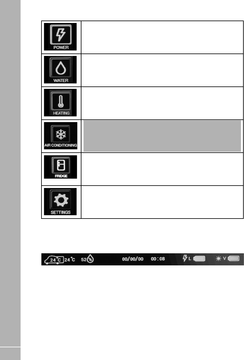
90
ELECTRICS
EC800 Control Panel ‘Header’ Information
At the top of the control panel screen there is a header or information bar which remains visible on all
screens. This is designed to provide quick reference information available at all times
* When a battery is not being charged a % remaining figure will be displayed. This figure is calculated from the battery voltage and
therefore should be used for guidance only.
Power Button. Press the power button to show the power information and
control screen. Here you can view battery levels, view charger and solar
current and press the more button (right arrow) to view 230V current. Press
the home button to return to the main screen.
Water Button. Press the water button to show the water tank information and
control screen. Here you can view tank levels and control related features.
Press the home button to return to the main screen.
Heating Button. Press the heating button to show the heating control screen.
Here you can control the heating system, select energy and temperature and
by pressing the more button (right arrow) you can set related timers. Press the
home button to return to the main screen.
Air-Conditioning Button. Press the Aircon button to show the aircon control
screen. Here you can select the operating mode, set the target temperature
and adjust the fan speed. Press the home button to return to the main screen.
Note: this button will only be visible if a CI-Bus equipped air conditioner is
installed, connected and enabled within the system.
Fridge Button. Press the fidge button to show the fridge control screen.
Here you can select the operating mode, set the cooling setting and view the
temperature status. Press the home button to return to the main screen.
Settings Button. Press the settings button to show the general settings screen.
Here you can set the date & time, screen brightness and screen on time. There
are also buttons on this screen to pair a Bluetooth device, delete Bluetooth
devices, or turn the key beep on / off. Press the home button to return to the
main screen.
Internal and
external
temperature in
degrees Celsius
The internal
temperature is
shown inside the
vehicle symbol.
Relative humidity
range
1 to 100%
Current date Current time *Leisure battery
status
Green = good,
Orange = fair, Red
= poor. Lightning
symbol indicates
charging from
the 230V battery
charger. *Vehicle
*Vehicle
battery status
Green = good,
Orange = fair,
Red = poor. Sun
symbol indicates
charging from the
solar panel.

91
ELECTRICS
Temperature Readings
The system uses two sensors to measure
internal temperature and humidity, and external
temperature. The internal temperature and
humidity sensor is furniture mounted within
the motorhome, and the external sensor is
mounted below the motorhome floor. The
figures displayed are for information only, and
it is hoped the information will be useful, for
example when checking temperatures remotely
during cold weather.
For vehicles fitted with Alde or Truma heating
systems, this sensor is not used to control the
heating temperature as it is measured above
the door by the Alde or Truma room sensor.
The readings on the heating system may vary
relative to the one shown on the control panel.
Water System Operation
The control panel pump button operates the
internal water pump drawing water from an on-
board water tank.
The water tanks (fresh & waste) incorporate
a level warning feature to warn the user when
the fresh water level drops below 25% or when
the waste water level reaches 100%. These
warnings can be enabled / disabled on the
control panel water screen.
If the water pump power is turned on and the
fresh water level drops to below 25% a warning
beep will be heard and a message will be
displayed on the control panel. To cancel the
warning, press the confirm button.
If the water pump power is turned on and the
waste water level rises to full (100%) a warning
beep will be heard and a message will be
displayed on the control panel. To cancel the
warning, press the confirm button.
These warnings will not be repeated unless the
water pump power switch is turned off and on
again. This is to ensure the warning does not
become a nuisance.

92
ELECTRICS
Water Tank Heaters (frost
protection) Operation
The EC652/653 features the ability to switch on
water tank heater to provide frost protection for
the fresh and waste tanks. The tank heaters will
only operate if there is over 25% in the relevant
water tank and the external temperature sensor
detects that the temperature falls below 2
degrees C. If the temperature rises above this
level the heaters will be switched off but the
feature will remain on.
If the tank heaters are turned on before starting
a journey, when the engine is started the tank
heaters will remain on for the duration of the
journey. When the engine is stopped the tank
heaters will remain on for a further 15 minutes.
If the engine is restarted within this 15 minute
period the tank heaters will remain on, again for
the duration of the journey.
When the engine is stopped the tank heaters will
turn off after a 15 minute period. To turn them
back on you will need to turn the control panel
on and then use the tank heaters button on the
water screen.
EC800 Water Tank Screen
Here you can view the on-board water tank
levels and control water tank related features.
Tank Heaters
Press the tank heaters button to turn on / off the water tank
heaters.
Level Alerts
Press the level alerts button turn on / off the water tank empty
/ full warnings.
Frost Alerts
Press the frost alerts button turn on / off the frost warnings.
Empty Fresh
Press this button to empty the fresh water tank (the press is
followed by a confirm button to avoid accidental operation)
Empty Waste
Press this button to empty the waste water tank (the press is
followed by a confirm button to avoid accidental operation)
iNote: Tank valves are normally closed and
will automatically close if the power is switched
off or if they have been open for more than 10
minutes.
iNote: When either tank is emptying the level
gauge and the related button will flash. Press
the empty button again and confirm if you wish
to cancel the emptying process.
iNote: Tank levels are measured in
increments of 25%
iNote: For fault finding please refer to the
water level sensor and cleaning page in the
services section

93
ELECTRICS
Lighting & Dimming Operation
The system contains up to two dimming
channels for groups of lights which can be
dimmed, turned on and turned off by this screen,
and can also be turned on and off by furniture
mounted switches.
The awning light on a motorhome can again
be controlled by a number of items, the control
panel awning light button, the App and the
lock and unlock system (dependant on system
setting being set to do so). Each item can toggle
the light on or off.
The Swift Command App can be used to both
configure and adjust the lighting and dimming.
EC800 Lighting Screen
Here you can turn on / off or adjust the
dimmable lighting levels.
On / Off
Press the centre of either dial to turn the dimmer channel on
or off. In the off state the centre of the dial shows the word
OFF. In the on state the level value is shown.
Up/ Down
Press the (+) or (-) buttons to increase ordecrease the
dimming level.
Solar Charge Management
The EC652/653 PSU incorporates a built-in
solar charge management feature, which will
monitor the input from a separate solar panel
and regulator. The Solar Active symbol will be
displayed on the control panel when there is
an amount of energy available to charge the
battery.
The voltage and current produced from the
regulator can be viewed on the control panel
display by selecting the Power menu item.
Depending on the charge state of the batteries,
the solar power will be directed to the required
battery and continuously monitored to ensure
optimum operation.
Power Screen (12V)
Here you can view battery levels, view charger
and solar current and press the more button
(right arrow) to view 230V current.
Smart Charging
Selected Battery
Use the selected battery button to select which battery you
wish to use or charge with the 230V charger.
230V Charging
If a battery is being charged by the 230V charger a ‘lightning’
symbol will be shown below the dial and adjacent to the
relevant battery in the header area.
Solar Charging
If a battery is being charged by the solar panel a ‘sun’ symbol
will be shown below the dial and adjacent to the relevant
battery in the header area.

94
ELECTRICS
Selected Battery
Use the selected battery button to select which battery you
wish to use or charge with the 230V charger.
230V Charging
If a battery is being charged by the 230V charger a ‘lightning’
symbol will be shown below the dial and adjacent to the
relevant battery in the header area.
Solar Charging
If a battery is being charged by the solar panel a ‘sun’ symbol
will be shown below the dial and adjacent to the relevant
battery in the header area.
Leisure Dial
The leisure dial shows the voltage of the leisure battery. Press
the centre of the dial to change to showing the leisure battery
current (+ positive value is charging and - negative value is
discharging)
Vehicle Dial
The leisure dial shows the voltage of the leisure battery. Press
the centre of the dial to change to showing the leisure battery
current (+ positive value is charging and - negative value is
discharging)
Solar Dial
The solar dial shows the current being supplied to the system
from the solar panel (if fitted).
The EC653/653 PSU incorporates a smart
charge feature, which monitors both leisure and
vehicle batteries and automatically adjusts and
directs the charger power (and solar power if a
solar panel is installed) to maintain the leisure
and vehicle batteries at an optimal level.
iNote: If the vehicle battery is isolated using
the Fiat ignition key isolator or similar, some
smart charging functionality will be lost, and
the available charge will be directed to the
leisure battery.
AC Current Limiter Operation
The power control system features a 230V
current monitoring system which allows
the mains hook up current to be displayed
on the control panel. The resolution of this
reading is 0.5A. A current limit setting can be
activated which if reached will switch off the
electric elements in the heating system (and
airconditioning if fitted and enabled), until such
time as the current drops and the elements will
be switched back on.
An example of this is if a kettle was to be
operated whilst the heating was on and the
current limit was reached then the heater
electric element would be temporarily
switched off, when the kettle had boiled then
the heater element would be switched back on
automatically.
This feature is particularly useful when abroad
on a low current supply. Setting the value to OFF
will disable this feature.
EC800 Power screen (230V)
Here you can view the 230V current and set the
230V current limiter.
AC Current
The dial on the left shows the 230V AC current being used by
the vehicle (from the site hook-up).
Set Limit
Press the centre of the dial to turn the AC current limiter on or
off. Press the (+) or (-) buttons to increase or decrease the
limit level. When on, the system will monitor the incoming
AC current and if the set limit is reached the 230V heating
element within the heating system will be temporarily turned
off until the current falls below the set limit.
iNote: For this feature to work correctly the
Heating mode must be set to Timer so that the
system can control the heating appliance.

95
ELECTRICS
EC800 Heating Controls
There are a number of heating systems that
can be controlled by the power control system.
The system will be preconfigured by the
manufacturer or supplying dealer. The related
control panel screens are shown below.
Heating screen
Here you can control the heating system, select
energy and temperature and by pressing the
more button (right arrow) you can set related
timers.
Mode
Set the mode to Manual to use the controls supplied by the
heating appliance manufacturer. Set the mode to Timer to
control the appliance by the EC800 control panel.
Note: The mode will automatically change
to App when you control the appliance by the
Swift Command app.
Status Temp Water
The status box shows you which timer is currently active, and
the temp and water boxes show the target room temperature
and water heater setting for the active timer.
Override
When operating in timer mode you can temporarily ‘override’
the timer room temperature by using the override feature.
Press the centre of the dial to turn the override on / off. Press
the (+) or (-) buttons to increase or decrease the required
emperature.
iNote: You can also override the room
temperature by making a change using
the appliance control panel (Alde & Truma
only). If you make a change the override
will automatically activate. The override
temperature will continue until the next timer
event time.
Truma CP+ Energy
Truma CP+ Energy
The energy, gas or electric setting will vary depending on the
appliance type.
For Truma Combi+ heating press the energy button to step
through the available settings. Gas is indicated by the flame
symbol and electric indicated by the lightning symbol.
Possible combinations are GAS, MIX1, MIX2, EL1 or EL2. One
electric symbol=1KW and two=2KW.
Alde 3030 Gas / Electric
Alde 3030 Gas / Electric
For Alde 3030 heating system press the gas button to enable
or disable the use of gas. Press the electric button to step
through the available electric settings. Gas is indicated by the
flame symbol and electric indicated by the lightning symbol.
Possible combinations are electric OFF, 1KW, 2KW or 3KW
and gas ON or OFF. One electric symbol=1KW, two=2KW and
three=3KW.

96
ELECTRICS
EC800 Refrigerator Controls
The main refrigerator settings can be set /
controlled by the EC800 control panel or the
Swift Command app. These controls work in
parallel with the ones on the fridge control
panel, so the settings cab be changed by either
method.
The related control anel sceens are shown
below.
For information in using the fridge from the Swift
Command app, please see the Swift Command
User Guide.
Fridge Screen. Here you can select the operating mode, set the cooling setting and view the
temperature status.
Mode Press mode button to select the required operating mode.
Select off to turn the fridge off.
Setting Use the setting (+) or (-) buttond to increase or decrease
the cooling setting. 1 is low and 5 is maximum
Temperature The temperature status display shows the temperature
state of the fridge, with the optimal (central) position
being the ideal. If the fridge is too warm, incease the
cooling setting to reduce the temperature. If the fridge is
too cold, reduce the cooling setting accordingly.
Note that the fridge will take time to react to a setting change so please allow sufficient time for the
status to update after changing a setting or adding food.
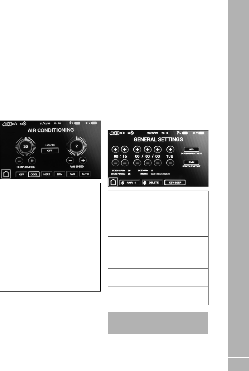
97
ELECTRICS
Air-conditioning
If your vehicle has been fitted with a compatible
air-conditioning unit then the settings can be set
/ controlled by the EC800 control panel, the air-
conditioner infrared remote control or the Swift
Command app.
The unit must be turned on with its power switch
before it can be controlled. The related control
panel screens are shown below. For information
in using the airconditioning from the Swift
Command app, please see the Swift Command
User Guide
EC800 Air-conditioning screen
Here you can select the operating mode, set the
target temperature and adjust the fan speed.
Lights
Press the lights button to control the LED light built into the
air-conditioning unit. Select on or off to turn the light on or off,
or select dimmed to allow the light to be controlled with other
dimmable lighting in the vehicle.
Mode
Press mode button to select the required operating mode.
Select off to turn the airconditioner off. Note that available
modes vary according to the model of air-conditioner fitted.
Temperature
Use the temperature setting (+) or (-) buttons to increase or
decrease the temperature setting. Available settings range
from 5 degrees to 30 degrees Celsius.
Fan Speed
Use the fan speed setting (+) or (-) buttons to increase or
decrease the fan setting.
Note that available settings vary according to the model of
air-conditioner fitted.
EC800 Bluetooth Pairing & Other
Controls
The EC800 control panel can display the
software version number of the Control Panel,
the PSU and the communicator / tracking unit.
Press the settings button to view the setting
screen which contains the related information.
The Bluetooth pairing process is covered
below. Further help with Bluetooth pairing is
available in the form of a help video which can
be viewed on the Sargent website in the Support
Information section.
EC800 General settings screen
Here you can set the date & time, screen
brightness and screen on time.
Time, Date & Day
Press the (+) or (-) buttons above or below each item to
adjust the value. Note that the system uses the 24 hour clock.
Screen settings
Press on the screen brightness button to adjust the screen
backlight level. Press on the screen timeout button to select
the time that the screen will stay illuminated for after a press
or touch.
Bluetooth Pair
Press the pair button to start pairing with your compatible
Bluetooth device. The pair button border will illuminate when
pairing is active. You can now pair your device to the system
following the devices instructions. Pairing remains active for
1 minute and is then turned off automatically.
Bluetooth Delete
Press the delete button to delete any Bluetooth pairings from
the system.
Key Beep
Use the key beep button to turn on / off the beep sound when
a button is pressed.
iNote: Setting changes are saved when you
press the home button to return to the main
screen.

98
ELECTRICS
Electric Step Operation
On vehicles fitted with an electric step, this is
operated by a button near the entry door. Press
and release the button to move the step in or
out. One press of the button will move the step
out; a further press will move the step in again.
If the engine is started the step will move in
automatically, after a short warning buzzer. If
this operation fails due to an obstacle a buzzer
will sound continuously to warn that the step is
still out, and therefore requires your attention.

99
99
ELECTRICS
8.23 System Warnings
The system incorporates a number of warnings that are active at specific times. These are
summarised below, and also covered by relevant sections of this manual.
When a warning is active a warning box will appear on the control panel screen containing a
description of the warning along with an audible beeping sound.
Warning When Type
Fresh water
level low
With pump turned on and fresh
water level low (less than 25% full)
Only available when an on-board
tank is fitted.
Message on screen and 60 second
audible beep
Waste water
level full
With pump turned on and waste
water level full. Only available
when an on-board tank is fitted
Message on screen and 60 second
audible beep
Leisure battery
voltage low
With control panel power on and
leisure battery selected (as active
battery) and the voltage level falls
below 10V
Message on screen and 60 second
audible beep
With control panel power on and
leisure battery selected (as active
battery) and the voltage level is
below 9
Message on screen and 60 second
audible beep. If no action taken after 30
seconds then the system will switch the
power off to prevent severe discharge of
the battery
Note: This is an emergency cut off level to protect the battery from severe
damage. You should not rely on this cut off level during normal operation, but
manage your power consumption to a discharge level of 11.5V or above. This
cut off only applies to power drawn from the battery by the leisure equipment
that is controlled by the control panel power switch; it will not protect the
battery from discharge by permanently connected equipment.
Leisure battery
voltage high
With control panel power on or off
and leisure battery is selected (as
active battery) and the voltage
level rises above 15V
Message on screen and repeated beeps
from the control panel. The power is
automatically turned off. The beeping will
not stop until the fault is cleared.
Vehicle battery
warnings
If the vehicle battery is selected instead of the leisure battery, then similar
warnings to those described above are applied to the vehicle battery. The
vehicle battery low warning level is 10.9V
Engine running When the engine is started the
system power will be turned off
Message on screen stating ‘engine
running’.
Step extended
Step extended and engine
started
Message on screen and warning buzzer
Step jammed or obstructed

100
ELECTRICS
Warning When Type
Mains lead
(hook-up
cable) still
connected /
plugged in
When the engine is started and the
mains cable is still plugged in and
the charger is switched on
Message on screen and repeated beeps
from the control panel. The beeping
will not stop until the hook-up lead is
removed.
Heating system When set to control the heating
system, the EC800 control panel
will show related heating system
warnings, which will include the
error number and error description
Message on screen and 60 second
audible beep. Additional descriptive
information is available when using the
Swift Command App.
Refrigerator /
Fridge Freezer
When set to control the
refrigerator, the EC800 control
panel will show related warnings
which will include the error number
and error description
Message on screen and 60 second
audible beep. Additional descriptive
information is available when using the
Swift Command App.
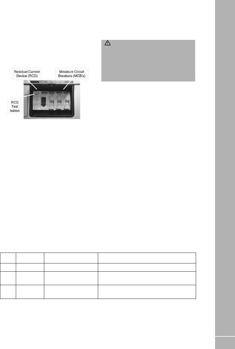
101
ELECTRICS
MCB Rating Output Wire Colour Description
1 10 Amps White 230V Sockets
2 16 Amps White (Yellow for heater) Extra 230V Sockets / Heating System
3 10 Amps Black (Blue for Whale
water heater)
Fridge / Charger / Auxiliary devices / Whale
Water Heater
8.24 System Technical Information
The following section provides further technical
information relating to the electrical system. You
can also access the supporting technical manual
from www.sargentltd.co.uk
Residual Current Device & Miniature
Circuit Breakers
The Residual Current Device (RCD) is basically
provided to protect the user from lethal electric
shock. The RCD will turn off (trip) if the current
flowing in the live conductor does not fully
return down the neutral conductor, i.e. some
current is passing through a person down to
earth or through a faulty appliance.
To ensure the RCD is working correctly, the test
button should be operated each time the vehicle
is connected to the mains supply.
The Miniature Circuit Breakers (MCB’s) operate
in a similar way to traditional fuses and are
provided to protect the wiring installation from
overload or short circuit. If an overload occurs
the MCB will switch off the supply. If this occurs
you should investigate the cause of the fault
before switching the MCB back on.
The following table shows the rating and circuit
allocation for the three MCB’s
Generator Usage
Caution should be used before connecting a
generator to your motorhome.
WARNING: Never start or stop the
generator while electrical loads are connected
and switched on. Start the engine, let it
stabilise and then connect the electrical load.
When stopping the generator, disconnect the
electrical load and let engine stabilise before
switching off.
Whilst some generators use electronic inverter
technology, others use a more basic principle
to generate the 230V supply. Preference should
be to choose a generator which produces a
consistent sinusoidal wave form with accurate
voltage control.
The Reverse Polarity warning light on the PSU
may illuminate when using a Generator. This
is a normal side effect when using some types
of generator. Instead of connecting the neutral
conductor to earth, some generators centre tap
the earth connection making both neutral and
live conductors 110V above earth. This 110V
difference causes the neon polarity indicator to
illuminate.
In most cases it is safe to use a generator, but
please consult the generator handbook for
further information.

102
ELECTRICS
Battery Charger
The system incorporates an intelligent
threestage battery charger.
During stage 1 the battery voltage is increased
gradually while the current is limited to start
the charging process and protect the battery.
At stage 2 the voltage rises to 14.4V to deliver
the bulk charge to the battery. When the battery
is charged, the voltage is decreased at stage
3 to 13.6V to deliver a float charge to maintain
the battery in the fully charged state. The
charger can be left switched on continuously as
required.
The battery charger / power converter also
provides power to the leisure equipment when
the mains supply is connected. This module
supplies DC to the leisure equipment up to a
maximum of 25 Amps (300 Watts), therefore
the available power is distributed between the
leisure load and the battery, with the leisure load
taking priority as per the following example:
Leisure
Load
Available power for battery
charging
5A 20A
10A 15A
15A 10A
20A 5A
WARNING: Under heavy loads the Battery
Charger case may become hot. ALWAYS
ensure the ventilation slots have a clear flow of
air. Do not place combustible materials against
/ adjacent to the charger.
Leisure Battery
A) Type / Selection
For optimum performance and safety it is
essential that only a proprietary brand LEISURE
battery is used and it is suggested to select a
battery from the NCC Verified Battery Scheme
with a typical capacity of 75 to 120 Ah (Ampere /
hours). Depending on the prospective use of the
vehicle the correct type should be selected (A, B
or C). A normal car battery is NOT suitable. This
battery should always be connected when the
system is in use.
The PSU is configured to work with standard
lead acid leisure batteries, and in most cases
is also compatible with the latest range of
Absorbed Glass Matt (AGM) batteries. The
system is also suitable for Lithium batteries with
built-in Battery Management Systems BMS).
Before fitting non-standard batteries please
check that the charging profile described in 3.3
is suitable for the type of battery by referring
to the battery documentation or battery
manufacturer.
Some vehicle installations can cater for two
leisure batteries connected in parallel. In these
cases it is recommended that two identical
batteries are used.
The battery feed is fitted with an inline fuse
between the battery and the electrical harness,
and is usually located immediately outside
the battery compartment or within 500mm of
the battery. The maximum rating of this fuse
is 20A per battery. If a single battery is fitted
to a motorhome, this fuse could be up to 40A,
however if two batteries are fitted each battery
should be fused at a maximum of 20A.

103
ELECTRICS
B) Installation & Removal
Always disconnect the 230V mains supply
and turn the PSU green charger switch to the
off position (button out) before removing or
installing the battery.
When connecting the battery, ensure that the
correct polarity is observed (black is negative
[-] and red is positive [+]) and that the terminals
are securely fastened. Crocodile clips must not
be used.
WARNING: Explosive gases may be
present at the battery. Take care to prevent
flames and sparks in the vicinity of the battery
and do not smoke.
C) Operation / Servicing
Under normal circumstances it should not be
necessary to remove the battery other than for
routine inspection of the terminals and “topping
up” of the battery fluid where applicable. Please
see instructions supplied with the battery.
iNote: Do not over discharge the battery.
One of the most common causes of battery
failure is when the battery is discharged below
the recommended level of approximately 10V.
Discharging a battery below this figure can
cause permanent damage to one or more of
the cells within the battery.
To prevent over discharge, the power control
system incorporates a battery protect circuit
that warns the users and then disconnects the
batteries when they fall below set values.
If a warning is active a beep will be emitted by
the control panel and information will be shown
on the screen. To cancel the warning, press
the select button. These warnings will not be
repeated unless the power switch is turned off
and on again. This is to ensure the warning does
not become a nuisance.
Battery Voltage
cut off
Action after
cut off
Notes
Vehicle 10.9V Battery selection is
changed from Vehicle
battery to Leisure
battery. If the leisure
battery is below 9V then
a further warning will
occur (see below).
This cut off level is designed to protect the
vehicle battery from over discharge. The 10.9V
level ensures there is sufficient power in the
battery to run the vehicle electronics and
start the vehicle. This cut off only applies to
power drawn from the battery by theleisure
equipment; it will not protect thebattery if you
leave vehicle circuits switched on, such as the
road lights.
Leisure 9V Power is turned off This is an emergency cut off level to protect
the battery from severe damage. You
should not rely on this cut off level during
normal operation, but manage your power
consumption to a discharge level of about
11.5V. This cut off only applies to power drawn
from the battery by the leisure equipment
that is controlled by the control panel
power switch; it will not protect the battery
from discharge by permanently connected
equipment.

104
ELECTRICS
12 Volt DC Fuses
WARNING: When replacing fuses
always replace a fuse with the correct value.
NEVER replace with a higher value / rating
as this could damage the wiring harness. If a
replacement fuse ‘blows’ do not keep replacing
the fuse as you could damage the wiring
harness. Please investigate the fault and
contact your dealer.
The following table shows the fuse allocation for the 13 fuses fitted to the PSU. Please note that fuses
are dependant on PSU versions, so not all fuses may be present.
Fuse Rating Fuse
Colour
Description
1 25 Amps White Battery Charger
2 7.5 Amps Brown Fridge Controls / Alarm
3 10 Amps Red 12V & USB Sockets / TV Amp
4 10 Amps Red Extractor, Cooker hood, Heki powered skylight. Aide or Truma Combi
Heating (Not En-Route), Whale Water Heater
5 10 Amps Red Appliances, Cooker, Toilet, Whale Space Heater, Locker Mount USB,
Tank Valves
6 10 Amps Red Water Pumps / Tank Heaters
7 7.5 Amps Brown Main lighting (not including spotlights with USB), Rear ambient
lighting, Offside awning light
8 7.5 Amps Brown Entry lights, Front ambient lighting
9 10 Amps Red Aide or Truma En-Route Heating, Marker Lights, En-Route lighting,
12V Sockets, WiFi & Satellite supply
10 10 Amps Red Awning Light (Doorside) / Electric Step
11 15/20 Amps Blue/
Yellow
Fridge 12V: 15A for undercounter fridge, 20A for tall fridge freezer
12 15 Amps Blue Towing 12V
13 15/20
Amps
Blue/
Yellow
Fridge D+: 15A for undercounter fridge, 20A for tall fridge freezer
The following table shows details of the fuse(s) located at the Leisure battery.
Fuse Rating Fuse Colour Description
Battery 1 40 Amps White Fuse remotely located near battery
Battery 2 40 Amps Brown Fuse remotely located near battery 2 (where fitted)
iNote: Fuses (2-13) have a Red LED below them which provides indication that the fuse has
blown. The charger fuse has a green LED which Indicates that the charger is working.

105
ELECTRICS
Fault Possible Cause Proposed Fix
No 230 volt
output from
PSU
Connecting lead between the site
and Leisure Vehicle not connected
Check and connect lead
RCD switched off Reset RCD
RCD not operating correctly Reset MCB by switching OFF (down
position) then back ON (up position), if
the MCB continues to fail contact your
Dealer as there is probably an equipment
or wiring fault.
No or deficient supply from site Contact site Warden for assistance.
Other fault Contact your Dealer
Reverse
Polarity light is
illuminated on
PSU
Mains Supply reversed? The reverse polarity light is designed
to illuminate when the Live and Neutral
supply has been reversed / crossed
over. If the light illuminates there is a
problem with the site supply or the cable
connecting the supply to your vehicle. The
light is designed to work on UK electrical
supplies (where the neutral conductor
is connected to earth at the sub station).
If you are using your vehicle outside the
UK this light may illuminate when no fault
exists. In these cases consult the site
warden for advice.
Generator being used ‘The Reverse Polarity warning light is on
when using my Generator’.
This is a normal side effect when using
some types of generator. Instead of
connecting the neutral conductor to
earth, some generators centre tap the
earth connection making both neutral and
live conductors 110V above earth. This
110V difference causes the neon polarity
indicator to illuminate. In most cases it is
still safe to use the generator, but please
consult the generator handbook for
further information.
8.25 Common Fault Table

106
ELECTRICS
Fault Possible Cause Proposed Fix
Control Panel
Problems
Control Panel has no display Check batteries and fuses, turn PSU
isolate switch and charger switch on and
ensure mains supply is connected.
Check control panel connecting lead at
PSU and behind Control Panel.
Contact your Dealer.
12V Power turns off Battery protect feature has operated to
protect the Vehicle battery and or the
Leisure battery.
Over voltage protection has been
activated, the control panel will display
a warning. A number of things can cause
this but the most common is the solar
panel, it is worth checking the regulator is
connected correctly and operating within
the correct parameters.
Engine has been started, all equipment
has been disconnected to meet EMC
requirements.
Control Panel locked / erratic
function
Observe control panel handling
instructions. Control panel software may
have crashed. Reboot control panel by
turning off the PSU isolate switch. Wait
30 seconds then turn the switch back on.
Check with your dealer that your system
has the latest software installed, as an
update may be available.
No 12 volt
output from
PSU
No 230V supply Check all above
Charger not switched on Turn charger switch on, switch will
illuminate
Battery not connected and / or
charged
Install charged battery
Power button on control panel not
switched to on
Turn power on at control panel
Battery flat / Battery fuse blown Recharge battery, check fuses, check
charging voltage is present at battery.
Fuse blown Check all fuses are intact and the correct
value fuse is installed as per fuse table.
Equipment switched off /
unplugged
Check equipment is switched on and
connected to the 12V supply
Other fault Contact your Dealer

107
ELECTRICS
Fault Possible Cause Proposed Fix
Pump not
working
Fuse blown Replace fuse with correct value as per
fuse table
Pump turned off Turn pump on by pressing the pump
button at the control panel
Comms not
working
Fuse/s blown Replace fuse with correct value as per
fuse table.
Lights turned off Turn Lights on by pressing the lights
button, use dimmer at the control panel.
Comms not
working
Bluetooth not paired Using System Settings menu, select
Bluetooth Pair option
Bluetooth not active on Device Ensure that the handheld device has
Bluetooth switched on and that the device
supports the Bluetooth 4 standard (BLE)
Bluetooth out of range Ensure the handheld device is within 7M
of the middle of the motorhome
Contact details
Sargent Electrical Services Limited provide a
technical help line during office hours. Please
contact 01482 678981 if you require technical
help.
For out of hour support please refer to the
support section of the Sargent web site
www.sargentltd.co.uk

108
ELECTRICS
8.26 Remote Access & Control
Swift Command App
The Swift Command app can be down loaded
from the Apple App Store or the Google Play
store.
A separate Swift Command User Guide is
available which covers the operation of the app.
Before you can use the App with your
motorhome you will need to create an account
and sign up to the free communication service.
This is a simple process and will be explained
further by your dealer at the vehicle handover.
Additional information is available at
www.swiftcommand.co.uk
Swift Command Web usage &
Description
In addition to the mobile App, you can also use
the same account and login details to access the
Swift Command web site.
Here you can update and amend your details,
look at location information and history, review
system information and historical data as well
as changing some system options and settings.
Swift Command SIM Coverage &
Usage information
The EC600 system contains Mobile SIM with
36 month contract, which commences upon
activation at the Dealership when your vehicle is
linked to your account.
Below is a list of the countries covered by the
SIM under a fair usage policy, a complete list is
available at request.
Austria, Belgium, Bulgaria, Cyprus, Czech
Republic, Denmark, Estonia, Finland, France,
Germany, Greece, Hungary, Iceland, Ireland,
Italy, Latvia, Liechtenstein, Lithuania,
Luxembourg, Netherlands, Malta, Norway,
Poland, Portugal, Romania, Slovakia, Slovenia,
Spain, Sweden, United Kingdom.
For vehicles shipping direct to Australia or New
Zealand a special world-wide SIM is fitted at the
Swift factory.
Please note that if a UK specification vehicle is
shipped to these countries the remote features
will not operate.
Replacement parts
The Control panel contains a small lithium
battery to maintain the clock when no other
energy supplies are available this will last in
excess of 5 years under normal conditions. The
battery is a CR2032 3.0V
The EC630 Communication module contains a
special backup battery pack which should last
in excess of 3 years under normal conditions.
The pack part number is 16308 available from
Sargent.
Updates
From time to time there may be updates to the
system firmware; these updates will be done at
service intervals by your dealership.
iNote:
Subscriptions:
Once the 3-year data subscription supplied
with your motorhome has expired, please
see www.swiftcommand.co.uk for renewal
details. The same website contains details
for the Tracking facility subscription, which is
purchased separately to the data subscription.

109
ELECTRICS
Outline Specification
INPUT 230V 230 Volts / 0 to 16 Amps + / - 10%
OUTPUT 230V
RCD protected, 2 x MCB outputs of 10A & 1 x MCB
output of 16A
Separate switched channels for heating system and
charger
Turn pump on by
pressing the pump
button at the control
panel
INPUT 12V 2 x 20A battery inputs via 2 x 4 way connectors
SOLAR INPUT
1 X Dedicated solar panel input capable of supporting
10A of solar power input (typically 180 to 200W) via a
2 way connector
Check the solar panel
rating plate to ensure
the maximum current is
<= 10A
OUTPUT 12V
25A total output via multiple switched channels
protected by 13 fused outputs
Integrated
CHARGER
Input 220-240 Volts AC +/- 10%, Frequency 50 Hz +/-
6%, Current 3A max.
DC Output 13.6 to 14.4 Volts nominal, Current 25
Amps max (300 Watts).
Signal INPUT
4 x Fresh water level, 4 x Waste water level, 1 x
Engine running, plus multiple vehicle connections,
sensor inputs for temperature & humidity
Fresh water negative
sensed Waste water
negative sensed
Data IN / OUT
CANBUS Data communication and power to
Control Panel via 6 way connector CI-Bus Data
communication to CI-Bus enabled devices via
RJ11/12 connector
IP rating IP31
Operating
temperature
Ambient 0 to 35° Celsius Charger case temperature
with full load 65° C Max
Automatic shutdown
and restart if
overheated /
overloaded
Dimensions
EC601, EC602,
EC652 & EC653
PSU
Overall size (HxWxD) 180 x 305 x 135mm Clearances
75mm above, 50mm left & right
Weight 3.8 Kg
EC800 Control
Panel
Overall size (HxWxD) 125 x 279 x 25mm Cut-out size
(HxW) 108 x 173mm + switch area
Fixing centres 250mm X
74mm Weight 380g
EC635 Comms
Module
Overall size (HxWxD) 55 x 116 x 85mm Weight 550g
EC840 Sensor Overall size (HxWxD) 20 x 35 x 38mm Weight 10g
8.27 Technical Data & Approvals
Equipment – EC652, EC653, EC800, EC635 & PX300

110
ELECTRICS
Approvals
System: BSEN 1648-1, BSEN1648-2 compliant,
BS7671: 2018 compliant
Residual Current Device: RCD 40A 30mA trip to
BS EN 61008
Miniature Circuit Breakers: MCB’s type C 4500A
breaking capacity to BSEN 60898
Electro Magnetic Compatibility (EMC) directive
2014/30/EU Certificate CE20071224-1
Battery Charger: BS EN 60335-2.29
CB, UL60950-1 Approved, IEC61000-4-
2,3,3,4,5,6,8,11, EN55024, Light industry
level, Criteria A, EN55022 (CISPR22) Class B,
EN61000-3-2,3
Low Voltage Directive: 2014/35/EU TUV-
014900-A1
Declaration of Conformity
Equipment: Leisure Power Control System
Model name: EC454, EC463 CP, EC652, EC643,
EC800 CP & PX300
I hereby declare that the equipment named
above has been designed to comply with the
relevant sections of the above referenced
approvals. The unit complies with all essential
requirements of the Directives.
Signed Name Position Manufacturer
I L Sargent Managing#
Director
Sargent Electrical Services Ltd
Unit 35, Tokenspire Business
Park Woodmansey, Beverley East
Yorkshire, United Kingdom
Date:
25/08/2021
Whilst every effort has been made to ensure the
accuracy and completeness of this document, no
guarantee is given against errors or omissions.
This document may be updated / improved over
time therefore please check with your dealer /
supplier for update information or visit
www.sargentltd.co.uk

111
ELECTRICS
8.28 Motorhome battery
WARNING: Use precaution when removing
or replacing the battery, as batteries contain
acid liquids which can cause severe injuries
and damage when handled incorrectly. Refer
to the cleaning and maintenance section.
Please also take into consideration when
manoeuvring a battery, that the weight may be
in excess of 20kg.
Your motorhome has been fitted with one or two
leisure batteries depending on size of vehicle
and expected electrical loads. The battery will
be housed in one of two ways:
Within a floor mounted compartment
Retained beneath the drivers seat or rear
seating
Floor mounted compartments are designed
to hold the battery securely and to contain any
electrolyte (acid) spillage. They are sealed from
the habitation compartment and a breather
pipe is fitted to ensure any build up of explosive
gases (hydrogen) is vented to the outside. If a
breather pipe is fitted it is important to ensure
that any replacement batteries are also fitted
with a breather pipe. The battery or batteries
should only be positioned in the appropriate
compartment, and be properly secured before
travelling.
iNote: The batteries fitted to your
motorhome in floor mounted compartments
must be kept upright.
When a leisure battery has been factory
installed below the driver’s seat or under a seat
base, the battery type used is specific to that
installation, and is of a type (Sealed AGM) that
allows a battery to be installed in a vertical or
horizontal orientation. Due to the construction
of this type of battery, it is not necessary to
vent the battery to the outside, and there is no
requirement to check and maintain electrolyte
levels.
WARNING: For your own safety, do not
store anything other than the leisure battery
in the battery compartment under the drivers
seat.
Battery removal
Step one
Remove the lower front seat fascia by pulling on
the clip feature located centrally on the upper
edge of the fascia. Using a small amount of
the force the fascia can be pulled in upwards
direction to fully detach it from the two lower
clip positions.
Step two
Release the battery harness by carefully
cutting the zip ties which are securing it to the
lower seat frame. Then disconnect the battery
harness connector by pulling firmly on each of
the large black connector plugs.
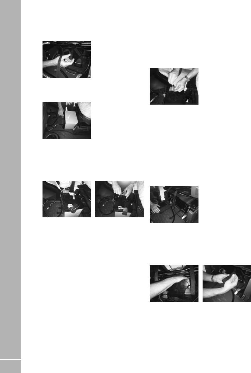
112
ELECTRICS
Step three
Remove the two fabric straps by loosening the
straps through the buckles.
Step four
Pull the battery forward out from under the seat
frame.
Step five
Carefully cut through the zip ties which are
securing the battery terminal covers in place
and remove the covers. Demount the battery
terminals using a 10mm spanner taking care not
to short the terminals.
Battery replacement
Step one
Place the new battery on the cab floor and
remount the battery terminals using a 10mm
spanner, taking care to observe the positive and
negative terminals. Refit the terminal covers
and secure in place using new zip ties.
Step two
Ensuring that the buckle are face down. Feed
the two fabric straps under the lower front and
back bars. Hook the rear of the strap over the
front top bar – this will prevent the strap being
dragged backwards when sliding the battery
into place.
Step three
Lie the battery on its side with the terminals
closest to the floor. Slide the battery into
position taking care not to drag the straps
backward.
Step four
Reach up above the battery and up through the
centre of the seat base to draw the strap back
from the top bar. Now the strap is located on top
of the battery re-secure the straps through the
buckles.
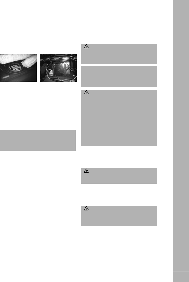
113
ELECTRICS
Step five
Tighten the strap as far as possible then slide
the seat forward and passing the tails through
the hole in the seat base. Then fully tighten the
straps and place the tail straps under the seat
when fully tightened. Ensure that the straps
are located next to the battery terminals to limit
movement of the battery.
Step six
Reattached the battery harness by firmly
pushing the electrical connector back together,
stow cable and secure using zip ties across the
front the seat frame.
Step seven
Reattach the lower front seat fascia by pushing
into lower clip positions first then rotating the
fascia until the upper central clip engages.
iNote: If an AGM battery is replaced, it must
be replaced by an equivalent AGM battery
which is suitable for a horizontal installation,
and does not require venting to the outside.
It is recommended that a good quality leisure
battery is always connected when the motor
home electrical system is in use. Leisure
batteries are a deep cycling rechargeable heavy
duty 12v battery designed to provide power for
lights and other electrical appliances. It should
be remembered that batteries suitable for the
electrical demands of a motorhome differ in
design from those for use with a car, and whilst
the system may operate with a car battery it is
strongly recommended that only a rechargeable
leisure type battery, maintained in good
condition, is used. The battery should be kept
topped up (charged) at all times. If two leisure
batteries are fitted additional care is needed,
as one battery deteriorates this can reduce the
lifespan of the other.
Replacement batteries should be a proprietary
brand leisure battery with a minimum 75Ah
capacity. Replacement batteries should be
checked dimensionally before purchasing, to
ensure fitment within the battery compartment,
as brands vary in size.
WARNING: When connecting the battery,
ensure that the correct polarity is observed
(black is negative and red/brown is positive)
and that the terminals are securely fastened.
iNote: Any replacement of an auxiliary
battery shall be of the same type and
specification as that originally fitted or
specified by Swift.
WARNING: If your motorhome is fitted
with Swift Command Tracker (by Sargent)
which monitors battery voltage. If you plan to
disconnect or remove your leisure battery for
maintenance or external charging, then please
contact the monitoring station before you
remove or disconnect the battery. If a leisure
battery is not fitted, please also contact the
Tracker monitoring station before removing
the mains hook up. The Swift Command
Tracker monitoring station can be contacted
on 0345 6027302.
Under normal circumstances it should not be
necessary to remove the battery other than for
routine inspection of terminals and (for non-
AGM batteries) ‘topping up’.
WARNING: Explosive gases may be
present at the battery. Take care to prevent
flames and sparks in the vicinity.
Your motorhome has been fitted with an in-line
fuse between the battery terminal and the
power supply unit. Do not use a higher rated fuse
as this may cause damage to your motorhome.
WARNING: Switch off all appliances and
lamps before connecting or disconnecting
the battery. Open flames and smoking are
prohibited around the battery compartment.

114
ELECTRICS
To preserve the life of your leisure battery and
charger please observe the following:
1. Do not leave all 12v lights powered at the
same time as this will drain your leisure
battery more rapidly.
2. If all 12v lights must be powered together,
ensure the battery is ‘in-circuit’ and that the
battery charger is turned on.
3. For optimum performance use the
transformer/charger unit with a leisure
battery attached.
4. Please note the auxiliary battery or batteries
supplied with your motorhome may not be
fully charged and should be charged for a
minimum of 24 hours before use. Battery
performance may be affected by a number
of things such as ambient temperature, age,
state of charge etc.
Cleaning and maintenance (Driver and rear
seating mounted batteries (AGM) and floor
mounted battery components).
• Always remove the battery and the power
cable before carrying out any maintenance of
the product.
• Before removing the clamps switch off all
electrical and gas appliances.
• Use a soft cloth or sponge and a non-acid/
abrasive detergent when cleaning the battery
tray and area.
• Before the camping season or extensive
travelling, check the under seat area for wear
on fitting and cables and replace if necessary.
• The cleaning of the battery area should only
be done after all power sources have been
switched off, in order to prevent a hazardous
situations.

115
ELECTRICS
8.29 Solar panel connection point or
Solar panel fitment
Depending on specification, a solar panel
connection point, or a solar panel and regulator,
may be installed in the motorhome.
Solar Panel Connection Point
If a connection point only is present, a solar
panel using this provision must provide a
fused and regulated output. From the provided
connection, the regulated output is taken to the
Power Supply Unit (PSU). This connection is
designed to be used with a maximum solar panel
size of up to 200W - if a solar panel or array of
greater than 200W is required, please contact
your dealer, Sargent Electrical or the Swift
Group for advice.
Solar panel installations should be undertaken
by trained technicians who are familiar with
the systems involved. Particular care should be
taken when making connections to solar panels,
which can generate high voltages ahead of a
regulator when exposed to light.
Motorhomes without factory fit solar energy
systems will have a two way connector present
at a high level within furniture (i.e within
wardrobe, either visible or behind a removable
cover). The output from a regulator, rated to suit
the chosen solar panel, should be connected to
this point.
Factory fitted Solar Energy System
Depending on specification, your motorhome
may be fitted with a solar panel of up to 200W,
and if a solar panel is fitted then a suitable solar
regulator will also be installed. This solar panel
and regulator may provide additional 12V power
whenever sunlight is available to the panel, and
this will be directed to the PSU.
Regulator operation
The regulator operates automatically, turning on
and off as required to charge and operate. When
the solar panel is exposed to a source of sunlight
the regulator starts to operate, and the indictors
on the solar regulator will indicate the regulator
is operating. See the instructions supplied
with the regulator for the full description of
indications.
Control Panel
When the solar panel is operating the leisure
battery voltage display value on the control
panel may increase, however this does depend
on the amount of load placed on the system and
the amount of power being generated by the
solar panel at that time.
Charging from Solar Panels
Solar charge directed to the PSU can be
distributed to the leisure battery, vehicle
battery, or each battery in turn. For further
details of selecting which battery receives the
solar charge, please see the EC800 or EC400+
instructions. Please note that solar charge can
only be directed to both leisure and vehicle
batteries, if the System Shutdown button is ON.
If System Shutdown is OFF, any available solar
charge will be directed to the vehicle battery
only.
If the vehicle battery is isolated, for instance via
the Fiat battery isolation feature, that battery
will not receive charge.

116
ELECTRICS
iNote: When the PSU System Shutdown
button is ON, there will be a small electrical
current draw, twenty-four hours a day, on
the selected battery - by default this is the
leisure battery. Similarly, if the Fiat or Ford
base vehicle battery is connected, there will
be a further small electrical current draw
on the vehicle battery from the Fiat or Ford
systems, twenty-four hours a day. Depending
on weather conditions and similar factors, the
solar panel and regulator may only be able to
provide charge for a few hours a day, which
may not be sufficient to maintain the condition
of leisure and vehicle batteries. Monitoring
of battery state of charge should be done
periodically.
Maintenance and cleaning
The solar panel will require cleaning periodically
in order to maintain the performance of the
panel. A caravan, car shampoo or simple soap
can be used, but do not use abrasive cleaners.
8.30 Accessory harnessing
Alarm Power Supply
A connection exists within the motorhome
harness, which can be used as a power supply
for an alarm or tracking system. For security
reasons, information regarding this is not
published; please contact your dealer for further
information.
Satellite Power Supply
Dependant on specification, in many
motorhomes a power supply harness is included
for use with roof mounted satellite systems. This
power supply is terminated in a 4-way connector
marked ‘SATELLITE’, and carries 12v positive,
12v negative, and a signal which can be used to
detect when the vehicle engine is running. (The
engine run signal is required by some systems to
automatically retract satellite dishes.
Tow Bar Connection
The addition of a tow bar requires an electronic
interface to ensure compatibility between the
combined road lighting on the motorhome and
the trailer, and the road light monitoring system
on the Fiat base vehicle.
Your motorhome already features an interface
which enables the use of LED road lighting on
the motorhome body, and there is connectivity
on this device for the addition of a tow bar. It is
important that the correct tow bar electrical
harness is used, and your Swift Group dealer can
order and fit this part for you. If a motorhome is
fitted with reverse sensors and a tow bar, these
reverse sensors will be disabled when a trailer
is connected.

117
ELECTRICS
8.31 Generator usage
Caution should be used before connecting a
generator to your motorhome.
WARNING: Never start or stop the
generator while electrical loads are connected
and switched on. Start the engine, let it
stabilise, then connect the electrical load. To
stop engine, disconnect the electrical load and
let engine stabilise before switching off.
Whilst some generators use invertor
technology, others use a more basic principle
to generate the 230v supply. Preference should
be to choose a generator which produces a
consistent sinusoidal wave form with accurate
voltage control.
The reverse polarity warning light may
illuminate when using a generator. This is a
normal side effect when using some types of
generator. Instead of connecting the neutral
and live conductors 110v above earth. This 110v
difference causes the neon polarity indicator to
illuminate.
In most cases it is safe to use a generator, but
please consult the generator handbook for
further information.
8.32 Habitation relay
Habitation relays are fitted to motorhomes by
manufacturers to comply with the following
legislation:
The Road Vehicles (Construction and Use)
Regulations 1986 Regulation 60 - Radio
interference suppression
European Community Whole Vehicle Type
Approval (ECWVTA) framework directive
2007/46/EC and EU Regulation 661/2009
(General Safety) mandates UNECE Regulation
10 (Vehicles with regard to Electromagnetic
compatibility).
A habitation relay must be fitted by
manufacturers, safe guarding the consumer,
the purpose of the relay is to disable
nonhomologated appliances/components
whilst the vehicle is in transit.
Unintentional electromagnetic energy can be
created by non-homologated devices within
the habitation compartment, which could cause
a malfunction of the base vehicles electronic
systems/components, including safety critical
items such as air bags, ABS braking etc.
In your motorhome the habitational relay is
within the power supply unit.

118
ELECTRICS
8.33 Fault Finding
The Swift Group recommends that electrical
fault finding is undertaken by a trained
Technician familiar with the systems involved.
The basic checks below are therefore limited
to items that can be checked without the use of
tools etc. If in any doubt please consult a Swift
dealer.
Power Supply
Fault Remedy
No 230v output from PSU See EC400+ or Swift Command information as appropriate
Reverse Polarity light illuminated See EC400+ or Swift Command information as appropriate
Reverse Polarity light illuminated See EC400+ or Swift Command information as appropriate
Control Panel Problems See EC400+ or Swift Command information as appropriate
Appliance Not Operating
Fault Remedy
Error code or fault light displayed
on appliance (eg fridge LCD
display)
Check appliance specific information for next steps
No display at appliance controls Check power supplies are available (electric hook up,
charger operating, battery in good state of charge). Majority
of appliances will not be operational when engine is running.
Ensure control panel is ON.
Check appropriate fusing in Power Supply unit
Internal Lighting
Fault Remedy
Lighting not operational Check power supplies are available Check control panel is ON
Locate furniture mounted switches, where appropriate
Check fuses on Power Supply Unit
Determine if light is LED or Tungsten / Halogen bulb, or
Fluorescent tube – check and replace bulb, or entire fitting as
appropriate

119
ELECTRICS
Road Lighting
Fault Remedy
Dashboard warning light
illuminated / groups of road lights
inoperative
If Tow Bar fitted check trailer lighting / disconnect trailer to
determine if this is the cause of the fault.
Check fuses in base vehicle dashboard or engine bay, see Fiat
or Ford handbook for details of which fuses are relevant
Check fuse in Power Supply Unit for auxiliary marker lights
(Amber side markers, Luton / upper rear markers)
Electric Step Operation (When fitted)
Fault Remedy
Step will not automatically retract
with engine start
Check fuses in Power Supply Unit.
Check mechanical condition of step – clean / lubricate if
appropriate.
Check other functions that are linked to the running of the
vehicle engine (i.e. fridge 12v operation). If these are also
inoperative contact dealer.
Step does not respond to furniture
switch
Check fuses in power supply unit
Check mechanical condition of step – clean / lubricate if
appropriate.
It is possible to link the operation of the step to the lock/
unlock commands from the central locking keyfob. If this
feature is enabled on your motorhome, check if operation of
the step via the central locking keyfob is possible. To enable /
disable the keyfob feature contact your dealer.
VLM Fusebox
Your motorhome is fitted with a secondary VLM interface, which is designed to work in conjunction
with the Fiat base vehicle. The secondary VLM allows the base vehicle to function with the LED rear
lights and still inform the user if the directional indicators are functioning or not, via the base vehicle
dash.
If a towed trailer is attached to this motorhome then the VLM fusebox will still allow the status of the
vehicle directional indicators to be relayed to the user along with informing the user if the directional
indicator on the towed trailer are functioning correctly.

120
ELECTRICS
Power Supply
Fault Remedy
Fresh water level sensor gives
incorrect readings
Use floor hatch within motorhome to access top of water
tank, or top of tank in bed box if internal (Escape), remove
sensor (4-screws) and clean probes
If problems persist, dealer assistance required for further
fault finding.
Waste water level sensor gives
incorrect readings
If possible, from below motorhome remove level sensor
from top of waste tank, and clean probes. Alternatively, clean
waste tank internal surfaces by flushing through with water
or cleaning agent.
If problems persist, dealer assistance required for further
fault finding.
Battery Discharge
Fault Remedy
Leisure battery discharging earlier
than anticipated
Have condition of leisure battery checked by dealer or tyre/
exhaust/battery specialist
If motorhome is not in use, ensure ‘SYSTEM SHUTDOWN’
button on Power Supply Unit is being used to isolate all
circuits
If motorhome is in use, see consumption table in handbook –
are several items perating simultaneously / is total load likely
to cause discharge.
Check charger is operational when mains hook up is present,
and that the charger is allowed sufficient time to replenish
battery / batteries.
Vehicle battery discharging earlier
than anticipated
If appropriate to battery, check condition and top-up battery
fluid if required
Have condition of leisure battery checked by dealer or tyre/
exhaust/battery specialist
If motorhome is not in use, see base vehicle handbook
section headed ‘periods of inactivity’. Consider use of vehicle
battery isolator
If motorhome is in use, check Power Supply Unit is configured
to charge / maintain both leisure and vehicle batteries.
(Contact dealer for further assistance if unsure)

121
ELECTRICS
Audiovisual Equipment
Fault Remedy
Rear view camera system
inoperative when reversing (if
fitted)
Check if camera system can be switched on manually, using
power button on rear view mirror, or dash mounted screen.
Check Reverse Lights are operational on rear of motorhome.
(Check base vehicle fuses if reverse lights are inoperative.)
Rear view camera system
inoperative whether moving
forward or reversing (if fitted)
Check fuses in habitation area fusebox (Power Supply Unit)
Radio switches off intermittently Radio will not remain on indefinitely when vehicle ignition is
switched off. Please see below or the Fiat handbook.

122
ELECTRICS

123
9. Fitted Equipment
9.1 Truma Combination Boiler . . . . . . . . . . . . . . . . . . . . . . . . . . . . . . . . . . . . . . . . . . . . . . . . . 124
9.2 Alde Compact 3030 Boiler . . . . . . . . . . . . . . . . . . . . . . . . . . . . . . . . . . . . . . . . . . . . . . . . . . 130
9.3 Alde Zonal Control . . . . . . . . . . . . . . . . . . . . . . . . . . . . . . . . . . . . . . . . . . . . . . . . . . . . . . . . . 131
9.4 Dometic absorption refrigerator . . . . . . . . . . . . . . . . . . . . . . . . . . . . . . . . . . . . . . . . . . . . 131
9.5 Edge / Voyager / Escape / Ascari Thetford Triplex Cooker . . . . . . . . . . . . . . . . . . . . 132
9.6 Using the Grill . . . . . . . . . . . . . . . . . . . . . . . . . . . . . . . . . . . . . . . . . . . . . . . . . . . . . . . . . . . . . 134
9.7 Maintenance & servicing . . . . . . . . . . . . . . . . . . . . . . . . . . . . . . . . . . . . . . . . . . . . . . . . . . 136
9.8 Kon-Tiki Thetford K1520 . . . . . . . . . . . . . . . . . . . . . . . . . . . . . . . . . . . . . . . . . . . . . . . . . . . 137
9.9 Microwave owner general user instructions . . . . . . . . . . . . . . . . . . . . . . . . . . . . . . . . . 138
9.10 Care of the microwave . . . . . . . . . . . . . . . . . . . . . . . . . . . . . . . . . . . . . . . . . . . . . . . . . . . . 140
9.11 Thetford Toilet . . . . . . . . . . . . . . . . . . . . . . . . . . . . . . . . . . . . . . . . . . . . . . . . . . . . . . . . . . . 140
9.12 Windows . . . . . . . . . . . . . . . . . . . . . . . . . . . . . . . . . . . . . . . . . . . . . . . . . . . . . . . . . . . . . . . . 142
9.13 Horrex Window Blinds . . . . . . . . . . . . . . . . . . . . . . . . . . . . . . . . . . . . . . . . . . . . . . . . . . . . 143
9.14 Blind Advice . . . . . . . . . . . . . . . . . . . . . . . . . . . . . . . . . . . . . . . . . . . . . . . . . . . . . . . . . . . . . 144
9.15 Skyview operating instructions . . . . . . . . . . . . . . . . . . . . . . . . . . . . . . . . . . . . . . . . . . . 144
9.16 Escape, Ascari and Voyager cab roof window . . . . . . . . . . . . . . . . . . . . . . . . . . . . . . 145
9.17 Roof lights . . . . . . . . . . . . . . . . . . . . . . . . . . . . . . . . . . . . . . . . . . . . . . . . . . . . . . . . . . . . . . . 145
9.18 Omni-vent . . . . . . . . . . . . . . . . . . . . . . . . . . . . . . . . . . . . . . . . . . . . . . . . . . . . . . . . . . . . . . . 150
9.19 Omni step single step (where fitted) . . . . . . . . . . . . . . . . . . . . . . . . . . . . . . . . . . . . . . 151
9.20 Thule T4200 / 8000 Omnistor Awning . . . . . . . . . . . . . . . . . . . . . . . . . . . . . . . . . . . . . . 151
9.21 Reverse Camera System . . . . . . . . . . . . . . . . . . . . . . . . . . . . . . . . . . . . . . . . . . . . . . . . . . 153
9.22 Cycle racks . . . . . . . . . . . . . . . . . . . . . . . . . . . . . . . . . . . . . . . . . . . . . . . . . . . . . . . . . . . . . . 154
9.23 Seat swivel (Driver/Passenger) . . . . . . . . . . . . . . . . . . . . . . . . . . . . . . . . . . . . . . . . . . . 155
9.24 Heated seats . . . . . . . . . . . . . . . . . . . . . . . . . . . . . . . . . . . . . . . . . . . . . . . . . . . . . . . . . . . . . 155
9.25 Side lockers . . . . . . . . . . . . . . . . . . . . . . . . . . . . . . . . . . . . . . . . . . . . . . . . . . . . . . . . . . . . . . 155
9.26 Aguti Smart Lounge (Escape, Voyager and Kon-Tiki) . . . . . . . . . . . . . . . . . . . . . . . 155
9.27 Bunk and luton bed safety . . . . . . . . . . . . . . . . . . . . . . . . . . . . . . . . . . . . . . . . . . . . . . . . 156
9.28 Powered Bed Mechanism (model specific) . . . . . . . . . . . . . . . . . . . . . . . . . . . . . . . . 156
9.29 Lippert Rise and Fall Island Bed (Kon-Tiki) . . . . . . . . . . . . . . . . . . . . . . . . . . . . . . . . 157
9.30 Tables . . . . . . . . . . . . . . . . . . . . . . . . . . . . . . . . . . . . . . . . . . . . . . . . . . . . . . . . . . . . . . . . . . . 158
9.31 Care of laminate tops, tables, furniture and doors . . . . . . . . . . . . . . . . . . . . . . . . . . 159
9.32 TV inlet . . . . . . . . . . . . . . . . . . . . . . . . . . . . . . . . . . . . . . . . . . . . . . . . . . . . . . . . . . . . . . . . . . 159
9.33 Status 570 Digital antenna system . . . . . . . . . . . . . . . . . . . . . . . . . . . . . . . . . . . . . . . . . 159
9.34 TV Brackets . . . . . . . . . . . . . . . . . . . . . . . . . . . . . . . . . . . . . . . . . . . . . . . . . . . . . . . . . . . . . . 160
9.35 Motorhome Wifi (where fitted) . . . . . . . . . . . . . . . . . . . . . . . . . . . . . . . . . . . . . . . . . . . 160
9.36 Cab Radios . . . . . . . . . . . . . . . . . . . . . . . . . . . . . . . . . . . . . . . . . . . . . . . . . . . . . . . . . . . . . . . 160
9.37 Shower . . . . . . . . . . . . . . . . . . . . . . . . . . . . . . . . . . . . . . . . . . . . . . . . . . . . . . . . . . . . . . . . . . 161
9.38 Motorhomes with external BBQ point . . . . . . . . . . . . . . . . . . . . . . . . . . . . . . . . . . . . . 161
9.39 The External Shower Point . . . . . . . . . . . . . . . . . . . . . . . . . . . . . . . . . . . . . . . . . . . . . . . . 162
9.40 Colour reference . . . . . . . . . . . . . . . . . . . . . . . . . . . . . . . . . . . . . . . . . . . . . . . . . . . . . . . . . 162
FITTED EQUIPMENT

124
FITTED EQUIPMENT
iNote: The instructions covering fitted
equipment to your motorhome were correct at
the time of going to print, and where possible,
hyperlinks and QR codes have been used,
which provide links to online versions of user
instructions. Owners handbooks are updated
annually and we take great care to try and
ensure their accuracy. However, the Swift
Group Limited cannot accept responsibility for
any changes that may be made in specification
or operating instructions to the equipment
described in this section after the time of going
to press.
Every care is taken to ensure that the
information provided in this handbook is correct
and easy to understand.
Separate manufacturers’ leaflets on many of the
components are also included in the
Owner’s Pack provided with this motorhome
and we recommend that you compare the
instructions provided via the handbook with the
component manufacturers literature,
to ensure the information provided is as
accurate as possible.
If you are in any doubt as to how to operate
the equipment in your motorhome, please
contact the component manufacturer’s service
department on the telephone number shown
on their component leaflet. If you remain in any
doubt, please contact your supplying dealer.
iNote: In the interest of safety, replacement
parts for an appliance shall conform to the
appliance manufacturer’s specifications and
should be fitted by them or their authorised
agents.
9.1 Truma Combination Boiler
The Truma Combination Boiler can be used in
the following ways:
To provide combined room heating and water
heating.
• Simultaneous heating of the room, and water
contained within the appliance. Often referred
to as Winter Mode.
To provide water heating only.
• Heating of the water within the appliance,
without room heating. Often referred to as
Summer Mode.
To provide room heating only, without water
heating.
• If the water system has not been primed,
meaning that there is no water within the
appliance, it is still possible to use the
Combination Boiler to heat the room.
Dual Fuel operation
The Truma Combination boiler has been
designed to run on gas or electric power, and the
optimum performance is obtained when used
in dual fuel mode, that is running on gas and
electric at the same time.
Running in dual mode has the following
benefits:
• The fastest possible heat up time, as the gas
burner combines with an electric element to
provide energy to heat your hot water and
warm your motorhome.
• The intelligent heat management system
automatically senses when the water and
room are nearing the required temperature
and then automatically turns off your gas
burner and operates solely on electric power,
conserving your gas.

125
• As hot water is used or the room cools the
Truma combination heater will continue to
operate on electric only, until a point where
the demands necessitate that additional gas
power is also required. An example for such
a demand could be for instance if the exterior
door was left open and the room temperature
dropped by 10 degrees in the space of a few
minutes, in this case the intelligent heat
management system would decide the best
way to get the room back to the required
temperature, would be to use both gas and
electric at the same time.
Operating the Truma Combination system on
electric or gas only will result in longer heat up
times for hot water, and room temperature, in
comparison to operating on dual fuel.
Operating on electric only may not in all cases
maintain a comfortable room temperature
especially in colder conditions.
Whilst taking energy consumption and the
environment into account, consider using the
Combi in Summer mode (water heating only)
when room or space heating is not required, but
may be needed in the near future. This ensures
the appliance is held at the same temperature
as the hot water setting chosen, and this can
reduce the time taken to provide warm air into
the living area, when room or space heating is
then selected.
Truma Heating System and Air Flow
The Swift Group undertakes considerable
testing of our products in cold chambers to
ensure they meet the BS EN 1646 Grade 3
standard and are usable in cold temperatures.
Butterfly outlets
The majority of air ducting outlets on models
equipped with Truma Combi heating systems,
are of the butterfly type. These may be opened
or closed by moving the flap within the fitting,
to adjust the balance of the heating output
throughout the motorhome. This can help offset
differences in blown air output, between outlets
close to the heating appliance, and those greater
distance away from the heating appliance.
This can also help adjust the temperature of the
bathroom, relative to the temperature of the
main living area and/or bedroom.
When these butterflies are closed in conjunction
with a high heating system output, and therefore
a high fan speed, a slight whistling sound can
occur. In this case, opening the outlet slightly
will reduce or remove the noise.
Closing too many outlets when the heating
system is producing a high output, can
cause the appliance to reach high operating
temperatures. This does not in general terms
effect the appliance, but can cause the appliance
to automatically shut down. This can cause an
interruption of the heating of the motorhome,
however heating will resume when the
appliance temperatures have reduced to a lower
level.
The output of the appliance, and therefore the
output of the blown air outlets, will generally be
higher when using Gas or Duel Fuel operation.
Electric only operation of the heating is rated
at up to 1.8kW , whereas Gas (or Dual Fuel)
operation is rated up to 4kW (3.8kW) or 6kW
(6.9kW), depending which model or Combi is
fitted.
The blown air fittings can also be rotated to
adjust the direction of air leaving the outlet, as
shown in the photo.
Truma Combination Boiler Control Panel and
Appliance Instructions
Please read the user instructions before using
the heating system. The instructions include
warnings regarding the safe use of the system,
and no liability whatsoever can be accepted
for damage or injury resulting from failure to
observe the instructions.
FITTED EQUIPMENT

126
FITTED EQUIPMENT
The heating system can be controlled by the
Truma CP+ controller above the entrance
door, or, if Swift Command is fitted, the Swift
Command control panel, App and remote
control features.
For Swift Command functions please see the
Swift Command literature and details within this
handbook.
For use of the CP Plus controller, and general
user instructions for the heating system
appliance, please read the Truma information
available at the following locations:
CP Plus Controller
https://bit.ly/3vPoHoD
Combi 4 Gas/Electric and Combi 6 Gas/ Electric
appliances
https://bit.ly/3p5H1pG
https://bit.ly/3SC9Sja
Electrical Operation of Truma Combination
Boiler
Before the heating system is used for heating
using electrical (230v) energy, the 230v
isolation button on the Sargent Power Supply
Unit must be switched ON, as shown in the
image below. To confirm a supply is available,
the button will be illuminated when a power
supply (mains hook up) is connected and the
button is ON.
Troubleshooting instructions (Combi heater)
In the event of a problem occurring, a warning
or error code will be displayed on the Truma
CP Plus control panel, along with a warning
triangle. Further warning information will also
be displayed on the Swift Command control
panel.
The Truma combi boiler (heater and water) has
two styles of error code warnings which are
shown on the CP+ display panel. Depending
on the nature of the fault, the boiler will
require resetting in a slightly different manner,
depending on the fault.
• Solid error warning code
• Flashing error warning code
Before trying to reset any faults please check
that the 12v supply is on, and depending on
which energy source is going to be used for
heating, either mains electricity is available and
switched on, and/or that the gas bottle is open
and ready to dispense gas.
The following table on the next page describes
causes and remedies to the various fault codes
that may be displayed on the Truma control
panel.
Once the fault has been rectified the fault can be
reset via the control panel
SOLID CODE
Using the control dial on the cp+ panel scroll
down to the bottom line where the triangle
appears.
• Press this button to acknowledge the error
• The error code and triangle should disappear
if the fault has been rectified
FLASHING CODE
• Scroll round (as above) to acknowledge the
error on the panel
• Leave the panel UNTOUCHED for 15 minutes –
This allows the user to check that fuel sources
are available, and is a regulatory time frame
• After 15 minutes the triangle will become solid
• The panel can be reset as per the above
process for SOLID

127
FITTED EQUIPMENT
Error
code
Cause Remedy
#17 Summer mode with empty
water container
Switch heater off and allow to cool. Fill boiler with
water
#18 Warm air temperature exceeded:
Not all warm air ducts are
connected
Check whether the 4 warm air ducts are connected
Circulated air intake blocked Remove the circulated air intake blockage
#21 Room temperature sensor or
cable faulty
Inspect the room temperature sensor cable, replace
if faulty
Check the resisitance of the room temperature sensor.
15°C - 16.2 kOhm / 20°C - 12,6 kOhm / 25°C
- 10.0 kOhm
Replace room temperature sensor if faulty
#24 Risk of low voltage. Battery
voltage is too low < 10.4V
Charge battery
#29 Frost Control heating element
has a short circuit
Disconnect heating element plug from electronic
control unit. Replace heating element
#42 Open window above cowl
(window switch)
Clode window
#43 Overvoltage > 16.4V Check battery voltage / voltage sources such as the
charger
#44 Low voltage. Battery voltage is
too low <10.0V
Charge battery. If necessary replace old battery
#45 No 230 V operating voltage Restore 230 V operating voltage
230 V fuse defective Replace 230 V fuse (see Combi operating instructions)
Overheating protection has
been triggered
Reset overheating protection (see Combi operating
instructions)
If the CP+ panel is reset 5 times, without the
fault being rectified the fault will become a
‘FLASHING’ CODE and will be locked for 15
minutes. If the control panel (cp+) is touched
within 15 minutes, the 15 minute ‘count’ will
restart. It is imperative that the panel is left
untouched during this time.
Truma Customer Service can be contacted on
01283 587960 or technical@trumauk.com if you
require further assistance.

128
FITTED EQUIPMENT
#255 Heater has no 12 V power
supply
Ensure 12 V power supply
No connection between heater
and control
panel
Make connection between heater and control
panel
#301
#417
Overvoltage > 16.4 V Check battery voltage / voltage sources such as the
charger
#303
#411
Risk of low voltage. Battery
voltage is too low < 10.4V
Charge battery
#401 Summer mode with empty
water container
Switch heater off and allow to cool. Fill boiler with
water
# 402 Open window above cowl
(window switch)
Clode window
# 407 Overvoltage > 16.4V Check battery voltage / voltage sources such as the
charger
# 408 Low voltage. Battery voltage is
too low <10.0V
Charge battery. If necessary replace old battery
# 412 No 230 V operating voltage Restore 230 V operating voltage
230 V fuse defective Replace 230 V fuse (see Combi operating instructions)
Overheating protection has
been triggered
Reset overheating protection (see Combi operating
instructions)
# 419 Gas cylinder empty Wait 15 minutes and reset fault
Error
code
Cause Remedy
#112
#121
#122
#202
#211
#212
Gas cylinder empty Replacing a gas cylinder
Gas cylinder or quick-acting
valve in the gas supply line
closed
Check gas supply and open valves
Gas pressure regulation
system iced up
Use regulator heater (EisEx)
Butane content in the gas
cylinder too high
Use propane. Butane is unsuitable for heating,
particularly at temperatures lower than 10 °C.
Combustion air infeed or
exhaust outlet is sealed
Inspect openings for obstructions (slush, ice, leaves,
etc.) and remove any obstructions
Gas pressure regulation
system faulty
Inspect / replace gas pressure regulation system
Truma Combi Heating fault codes 507, 516 or
517.
This fault will appear in the display of the Truma
Combi digital display in the Truma CP Plus
control panel. This is a preventative measure
to stop the heater constantly trying to restart if
there is no gas and is referred to as ‘gas lockout’.
iNote: If the fault 507, 516 or 517 is
displayed in the heater’s control panel,
switching the control panel on and off does not
help. This does not delete the fault, but blocks
the heater for 15 minutes. The heater is also
blocked for 15 minutes if the fault 507, 516
or 517 is deleted four times without the gas
supply being established.

129
FITTED EQUIPMENT
# 514 The 12V supply has been
interupted
Ensure the control panel of caravan / motorhome is
switched on. Ensure charger is switched on and / or
battery is connected
# 507
# 516
# 517
Gas cylinder empty Replacing a gas cylinder
Gas cylinder or quick-acting
valve in the gas supply line
closed
Check gas supply and open valves
Gas pressure regulation
system iced up
Use regulator heater (EisEx)
Butane content in the gas
cylinder too high
Use propane. Butane is unsuitable for heating,
particularly at temperatures lower than 10 °C.
Gas pressure regulation
system faulty
Inspect / replace gas pressure regulation system
Gas pressure regulation
system faulty
Inspect / replace gas pressure regulation system
Gas supply interupted
Remedying flashing fault
507 / 516 / 517 (gas supply
interrupted)
Restore the gas supply, for example by connecting a
full gas cylinder.
Then confirm or delete the fault code by tapping the
rotary push button. Please note that the first tap might
only activate the backlighting of the control panel.
The heating then starts automatically if there is a
heating requirement.
The fault code 507, 516 or 517 flashes because the
heater is still in a 15-minute blocking time. This was
possibly caused by the heater control panel being
switched off or because the heater’s 12-Volt supply
was interrupted. The heater is also blocked for 15
minutes if the displayed fault is deleted four times
without the gas supply being restored.
• Wait out the 15-minute blocking time for the heater.
During this time, do not switch off the heater’s
control panel and also do not interrupt the power
supply.
• As soon as the heater’s blocking time has expired,
the fault is then displayed permanently rather than
flashing. It can now be deleted as described in the
point above
# 607 Max. number of fault resets
reached
Wait 15 minutes and reset fault
# 621 Room temperature sensor or
cable faulty
Inspect the room temperature sensor cable, replace
if faulty
Check the resistance of the room temperature sensor.
15 °C – 16.2 kOhm / 20 °C – 12.6 kOhm / 25
°C – 10.0 kOhm
Replace room temperature sensor if faulty
# 624 FrostControl heating element
has a short circuit
Disconnect heating element plug from electronic
control unit. Replace heating element
If these measures do not remedy the fault or if fault codes are displayed that you cannot find in the
troubleshooting guide, contact Truma Service.

130
FITTED EQUIPMENT
9.2 Alde Compact 3030 Boiler
The Alde Boiler can be used in the following
ways:
To provide combined room heating and water
heating.
• Simultaneous heating of the room, and water
contained within the appliance.
To provide water heating only.
• Heating of the water within the appliance,
without room heating.
To provide room heating only, without water
heating.
• If the water system has not been primed,
meaning that there is no water within the
appliance, it is still possible to use the Alde
3030 to heat the room.
Alde 3030 Control Panel and Appliance
Instructions
Please read the user instructions before using
the heating system. The instructions include
warnings regarding the safe use of the system,
and no liability whatsoever can be accepted
for damage or injury resulting from failure to
observe the instructions.
The heating system can be controlled by the
Alde 3030 colour touch screen controller fitted
above the entrance door, or, if fitted, the Swift
Command control pane, App and remote control
features.
For Swift Command functions please see the
Swift Command literature and details within this
handbook.
For use of the 3030 colour touch screen control
panel, and the 3030 system appliance, please
read the information available at the following
locations:
3030 Alde Heating System
https://bit.ly/3QfBlpg
Electrical Operation of Alde 3030 Heating
System
Before the heating system is used for heating
using electrical (230v) energy, the 230v isolation
button on the Sargent Power Supply Unit must
be switched ON, as shown in the image below.
To confirm a supply is available, the button will
be illuminated when a power supply (mains
hook up) is connected and the button is ON.
Heating/Hot
water

131
FITTED EQUIPMENT
9.3 Alde Zonal Control
The Kon-Tiki range of motorhomes is fitted
with a second thermostat, which can be used to
control the heating system.
In normal use (and on other ranges), the room
temperature is measured by a sensor within the
Alde touch screen control panel. With the Zonal
control, it is possible to select room temperature
measurement at this control panel position, or,
via the secondary temperature sensor fitted in
the rear lounge or sleeping area.
Typical 2nd thermostat and switch installation
The 2nd sensor is a circular furniture mounted
device, which has the word ‘Alde’ embossed on
its surface. Next to the sensor, a Black round
switch will feature ‘0’ and ‘1’ markings.
With the switch in the ‘0’ position, the room
temperature will be measured at the Alde touch
screen control panel.
With the switch in the ‘1’ position, the room
temperature will be measured at the 2nd
temperature sensor position.
9.4 Dometic absorption refrigerator
Before you start using the refrigerator, please
read the operating instructions carefully.
These instructions provide you with the
necessary guidance for the proper use of your
refrigerator. Observe in particular the safety
instructions. Observation of the instructions
and handling recommendations is important
for dealing with the refrigerator safely and for
protecting you from injury and the refrigerator
from damage. You must understand what you
have read before you carry out a task.
Keep these instructions in a safe place close to
the refrigerator so they may be referred to at
any time.
Your motorhome is fitted with an absorption
refrigerator from the Dometic range. The exact
model fitted varies, and the model fitted can
be confirmed by the data label fixed within the
fridge compartment. This label will feature a
model number in the format RM8406, RMS8556,
RML9336L, RMD8556 or similar.
Using this model number, please read the user
instructions for the refrigerator, which are
available from the following location:
http://td.dometicgroup.com/swift.php
If you are unable to view the documents on line,
please contact the supplier, your dealer or Swift
for an electronic or paper copy.
iNote: Gas operation of fridges – gas
lockout
If the fridge makes three unsuccessful
attempts to switch to gas mode, further
action may be required before gas operation
is possible. This could occur if a gas bottle is
empty, or if the fridge is switched on before the
valve on the gas bottle is opened. The display
on the fridge will show flashing LED’s against
the gas symbol and the warning symbol.
If this does happen, first check that a gas
supply is available: After checking the valve on
the gas bottle is open, and that the taps on the
gas manifold are in the correct position, light
one of the gas burners on the hob for a few
seconds to confirm gas is available.
Next, at the fridge, press the power ON/
OFF button for 2-3 seconds until the fridge
beeps, this will clear the warning, and normal
automatic selection of energy sources will
resume. If the button is pressed for slightly
longer, the fridge will switch off. In the event
of this happening, simply use the same power
button to turn the fridge back on, then press
again for 2-3 seconds to clear the warning.
Please note the fridge also has a TANK STOP
feature, which prevents gas operation for 15
minutes immediately after 12v operation, this
prevents the fridge from attempting to light
the gas while re-fuelling mid journey. Please
take this 15 minute delay into account if the
fridge switches from 12v operation to gas
operation.

132
FITTED EQUIPMENT
9.5 Edge / Voyager / Escape / Ascari
Thetford Triplex Cooker
Cooker 3 burner with combined grill
and oven / cooker 3 burner + electric
hotplate with separate grill and oven
Burner operation
Important
• Although each burner will support pans
from 10 to 22cm, care should be taken not to
overload the appliance as performance may
be reduced.
• The following pan sizes are the maximum:
• Auxiliary Burner:- Ø200mm Semi-Rapid
Burner:- 2x Ø200mm or 1x Ø220mm with 1x
Ø180mm
Electric Hotplate:- Ø180mm
• When using small pans the flames should not
spread beyond the base of the pan as this will
reduce the efficiency of the burner.
• Avoid old or misshapen pans as these may
cause instability.
• The lid must be opened fully prior to using the
hotplate burners.
Using the Hotplate Gas Burners
1. Ensure gas cylinder is connected and turned
on and the shut off valve at the manifold is
open. In the event of a gas smell turn off at
gas cylinder and contact supplier.
2. Flame supervision: Each burner is
controlled individually and is monitored
by a thermocouple probe. In the event
of the burner flames being accidentally
extinguished, turn off the burner control and
do not attempt to re-ignite the burner for at
least one minute.
3. To light: Push in the control knob and turn
to full rate – see Fig.1. Hold a lighted match
or taper to the burner and push the control
knob in and hold. It is necessary to hold
the knob depressed after the burner has
ignited for approximately 10 - 15 seconds,
to allow the thermocouple probe to reach
temperature, before releasing the knob.
Should the flame go out when the knob is
released, the procedure should be repeated
holding the knob depressed for slightly
longer.
4. For models fitted with Spark Ignition the
procedure is similar except that the burner
can be ignited by depressing the ignition
button, which is located on the fascia. If
the burner has not lit within 15 seconds the
control knob should be released and the
burner left for at least 1 minute before a
further attempt to ignite the burner.
5. For simmering, turn the knob further anti-
clockwise to the low rate position.
6. To turn off: Turn the control knob until the
line on the control knob is aligned with the
dot on the control panel. Always make sure
the control knob is in the off position when
you have finished using the hotplate burners.

133
FITTED EQUIPEMNT
WARNING:
Glass lids may shatter when heated. Turn off
the hotplate and allow it to cool before closing
the glass lid
Remove all spillage from the surface of the
glass lid before opening.
The glass lid has the tendency to snap shut
towards the end of lowering.
This is caused by the travel lock action of the
hinges as it is activated.
Make sure all fingers are removed from
appliance when closing the lid.
WARNING: The use of the gas hobs will
generate heat. We recommend, to avoid
excess build-up of heat around the cooker
area, the window is left opened when cooking
to allow for additional ventilation.
WARNING (Select Compact C404 / Ascari
344):
Do not use the hob unless the bed is lifted to
the highest stowage position.
IMPORTANT
• Depending on specification, your appliance
may be fitted with a glass lid shut-off system,
which cuts off the power to all hotplate
burners (gas and electric) if the lid is closed.
• Ensure the glass lid is in the open and upright
position before turning on the hotplate
burners.
• Not all models are fitted with the shut-off
system.
iNote: The cooker has a glass lid safety shut
off switch that turns off the gas hob burners
and electrical hotplate, when the glass lid is
placed down on the hob. The grill and oven
functions will still operate as normal, with lid
up or down.
Operation
WARNING: The grill must only be used with
the door open.
On combined grill and oven cookers the heat
deflector below the fascia should be pulled
out prior to lighting the grill. Never adjust the
heat deflector position without using hand
protection i.e. oven gloves. See Fig. 2
On separate grill and oven cookers the grill
area can get hot when the oven is in use, even
if the grill is switched off.
Care should be taken when removing pans
from the grill, i.e. use of oven gloves, and by
making use of the removal grill pan handle.
Important
• The grill pan supplied is multi functional, for
use in grill or oven.
• The handle design allows removal or insertion
whilst the pan is in use.
• Always remove the handle when the pan is in
use.
• The grill MUST only be used with the door
open.

134
FITTED EQUIPEMNT
9.6 Using the Grill
Fig. 2
1. Ensure gas cylinder/supply is connected and
turned on. In the event of a gas smell turn off
at gas cylinder/mains and contact supplier.
2. To light: Open door, pull out heat shield (Fig.
2) push in the control knob and turn to full
rate – see Fig 1 (page 132). Hold a lighted
match or taper to the burner and push the
control knob in and hold. The burner should
ignite and the control knob should be held in
for 10 -15 seconds before release.
If the burner goes out, repeat procedure holding
control knob for slightly longer.
3. For models fitted with Spark Ignition the
procedure is similar except that the burner
can be ignited by depressing the ignition
button, which is located on the fascia.
Ignition must be carried out with the door
open, and if the burner has not lit within 15
seconds the control knob should be released
and the grill left for at least 1 minute before a
further attempt to ignite the burner.
iNote: the grill must only be used with the
door open.
4. On first use of the grill, it should be heated
for about 20 minutes to eliminate any
residual factory lubricants that might impart
unpleasant smells to the food being cooked.
A non-toxic smoke may occur when using for
the first time so open any windows and turn
on mechanical ventilators to help remove
the smoke.
5. Although the grill does heat up quickly, a few
minutes preheat is recommended.
6. Flame Failure Device (FFD): the grill burner
is fitted with a flame sensing probe, which
will automatically cut off the gas supply in
the event of the flame going out. In the event
of the burner flames being accidentally
extinguished, turn off the burner control and
do not attempt to re-ignite the burner for at
least one minute.
7. It is normal for the flames on this burner to
develop yellow tips as it heats up.
8. A reversible grill pan trivet enables the
correct grilling height to be achieved.
Fast Toasting
trivet in high position
Grilling Sausages
trivet in high position
Grilling Steak/Bacon
trivet in high position
Grilling Chops, etc
trivet in low position
Slow Grilling
trivet removed
9. To turn off: turn the control knob until the line
on the control knob is aligned with the dot
on the control panel. Always make sure the
control knob is in the off position when you
have finished grilling.
Important:
• The pan supplied with the appliance is multi
functional, for use either whilst grilling or
when using the oven.
• The handle design allows removal or insertion
whilst the pan is in use.
WARNING: Pans must not touch the
glass lid.
iNote: To avoid heat build up around the hob
open the kitchen window slightly to allow the
heat to dissipate.
Operation
Important
• If the appliance is fitted with a cooling system.
The cooling fans should automatically switch
on a couple of minutes after the grill and/or
oven is turned on, and will remain on even
after the appliance has been switched off.
• The fans should automatically switch off a few
minutes after the appliance has been switched
off, when the front of the appliance has cooled
sufficiently.
• A constant 12V supply is necessary at all
times to ensure the cooling system operates
correctly.

135
FITTED EQUIPEMNT
Using the Oven
1. Ensure gas cylinder/supply is connected and
turned on. In the event of a gas smell turn off
at gas cylinder/mains and contact supplier.
2. To light: Open door, push in the control knob
and turn to full rate (240°C). Hold a lighted
match or taper to the burner and push the
control knob in and hold. The burner should
ignite and the control knob should be held
in for 10 -15 seconds before release. If the
burner goes out, repeat procedure holding
control knob for slightly longer.
3. For models fitted with Spark Ignition the
procedure is similar except that the burner
can be ignited by depressing the ignition
button, which is located on the fascia.
Ignition must be carried out with the door
open, and if the burner has not lit within 15
seconds the control knob should be released
and the oven left for at least 1 minute before
a further attempt to ignite the burner.
4. Place the oven shelf in the required
position and close the door. Set control
knob to approximately 200°C and heat the
oven for about 30 minutes to eliminate
any residual factory lubricants that might
impart unpleasant smells to the meals being
cooked. A non-toxic smoke may occur when
using for the first time so open any windows
and turn on mechanical ventilators to help
remove the smoke.
5. Although the oven does heat up quickly, it
is recommended that a 10 minute preheat
be allowed. The oven should be up to full
temperature in about 15-20mins.
6. To turn off: turn the control knob until the line
on the control knob is aligned with the dot on
the control panel.
7. Shelf: the shelf has been designed to allow
good circulation at the rear of the oven and is
also fitted with a raised bar to prevent trays
or dishes making contact with the back of the
oven. To remove a shelf, pull forward until it
stops, raise at front and remove.
WARNING: The pans and trays supplied
with this appliance are the maximum sizes
recommended for use. Larger pans and
trays may restrict good circulation of heat,
increasing cooking times.
Oven Temperature Control
The temperature in the oven is controlled
by a thermostatic gas tap and is variable
over the range 130°C to 240°C. Approximate
temperatures for the settings on the control
knob are shown in the table below. The
temperatures indicated refer to the centre of
the oven and at any particular setting the oven
will be hotter at the top and cooler towards the
base.
The variation between top and centre, and
centre to bottom is approximately equivalent to
one gas mark. Good use can be made
of the temperature variation in several dishes
requiring different temperatures may be cooked
at the same time. In this way maximum benefit
can be obtained from the gas used to heat the
oven. Care should be taken not to overload the
oven, adequate spacing being used to allow free
circulation for heat.
Operation
Cooking Guidelines
Best results will be obtained by the shelf
positions in this guide. It is not necessary to
preheat the oven but advisable for a range of
dishes. The oven is capable of full temperature
in 15-20 minutes.
Most cookery books give details of the shelf
positions and gas mark settings for each recipe.
If in doubt about a recipe you intend to use, study
the recipe carefully then find a similar dish in our
guide and use our shelf position and gas mark
setting recommendation.

136
FITTED EQUIPEMNT
When roasting with aluminium foil care must be
taken that the foil does not impair circulation or
block the oven flue outlet.
Gas Mark Temperature
(Centre - Shelf Pos. 2)
1/4 - 1/2 265 - 275°F 130-135°C
1 285 140
2 300 150
3 330 165
4 355 180
5 385 195
6 410 210
7 430 220
8 445 230
9 465 240
iNote: Shelf positions are from the top
down.
Do’s and don’ts
Do read the user instructions carefully before
using the appliance for the first time.
Do allow the oven to heat before using for the
first time, in order to expel any smells before the
introduction of food.
Do clean the appliance regularly.
Do remove spills as soon as they occur.
Do always use oven gloves when removing food
shelves and trays from the oven.
Do check that controls are in the off position
when finished.
Don’t allow children near the cooker when in
use. Turn pan handles away from the front so
that they cannot be caught accidentally.
Don’t allow fats or oils to build up in the oven
trays or base.
Don’t use abrasive cleaners or powders that will
scratch the surfaces of the appliance.
Don’t under any circumstances use the oven as
a space heater.
Don’t put heavy objects onto open grill and oven
doors.
Leaks
If a smell of gas becomes apparent, the
supply should be turned off at the cylinder
IMMEDIATELY.
WARNING: Extinguish naked lights
including cigarettes and pipes. Do not
operate electrical switches. Open all doors
and windows to disperse any gas escape.
LPG gas is heavier than air; any escaping
gas will therefore collect at a low level. The
strong unpleasant smell of gas will enable the
general area of the leak to be detected. Check
that the gas is not escaping from an unlighted
appliance. Never check for leaks with a naked
flame, leak investigation should be carried out
using a leak detector spray.
9.7 Maintenance & servicing
Important
• Shut off gas supply at isolating valve, switch
off electric supply and ensure all parts are cool
before cleaning or servicing
• All servicing must be carried out by an
approved competent person.
• After each service the appliance must be
checked for gas soundness
• This appliance must not be modified or
adjusted unless authorized and carried out by
the manufacturer or his representative.
• No parts other than those supplied by
the manufacturer should be used on this
appliance.
• If the supply cord is damaged, it must only
be replaced by the manufacturer or his
representative in order to avoid a hazard.
This appliance needs little maintenance other
than cleaning. All parts should be cleaned
using warm soapy water. Do not use abrasive
cleaners, steel wool or cleansing powders.
When cleaning the burner ring it is essential to
ensure that the holes do not become blocked.
The control knobs are a push fit and can be
removed for cleaning. They areinterchangeable
without affecting the sense of operation.

137
FITTED EQUIPEMNT
9.8 Kon-Tiki Thetford K1520
iNote: Before using the Hob, Grill or
Oven for the first time carefully read the
cooking appliance manufacturer’s operating
instructions supplied with your motorhome.
These instructions provide you with the
necessary guidance for the proper use of
your Hob, Grill or Oven. Observe in particular
the safety instructions. Observation of the
instructions and handling recommendations
is important for dealing with the appliance
safely and for protecting you from injury and the
appliance from damage. You must understand
what you have read before you carry out a task.
Keep these instructions in a safe place close
to the appliance so they may be referred to at
any time. For the latest version of the Thetford
Manual, please visit:
https://bit.ly/3BVxIQI
WARNING:
Appliances and accessible parts become hot
during use.
Always use hand protection, e.g. oven gloves,
when loading items into or removing them
from the oven or grill.
Avoid touching heating elements.
Children less than 8 years of age shall be kept
away unless continuously supervised.
Children shall not play with the appliances.
Unattended cooking on a hob with fat or oil can
be dangerous and may result in fire.
Never extinguish a fire with water, switch off
the appliance and cover flame with lid or fire
blanket.
Danger of Fire: Do not store items on the
cooking surface.
CAUTION:
• Do not use harsh abrasive cleaners or sharp
metal scrapers to clean the hob glass lid or
oven door glass since they can scratch the
surface, which may result in shattering of
the glass.
• Never use a steam cleaner to clean
appliance.
WARNING: Before using the appliances
for the first time, remove all accessories and
packing in the grill and oven, including any
surface protection film, i.e. plastic coating.
Gas Operation
Ensure the gas cylinder is turned on and the
oven / hob gas isolation valve is open at the
manifold. The burners on these appliances have
fixed aeration and no adjustment is required.
Depending on the gas being used, the burners
should flame as follows:
Propane - The flames should burn quietly with a
blue/green colour with no sign of yellow tips.
Butane - Normally on initial lighting, as small
amount of yellow tipping will occur and then
slightly increases as the burner heats up.
iNote: For safe use of gas see gas safety
advice on page 59
WARNING: The grill must only be used with
the door open.
Glass Lids
Depending on specification, your appliance may
be fitted with a glass lid shut-off system, which
cuts off the power to all hotplate burners (gas
and electric) if the lid is closed.
• Ensure the glass lid is in the open and upright
position before turning on the hotplate
burners.
WARNING:
• Glass lids may shatter when heated. Turn
off the hotplate and allow it to cool before
closing the glass lid
• Remove all spillage from the surface of the
glass lid before opening.
• The glass lid on some models has the
tendency to snap shut towards the end of
lowering. This is caused by the travel lock
action of the hinges as it is activated. Make
sure all fingers are removed from appliance
when closing the lid.

138
FITTED EQUIPEMNT
Do’s and Don’ts
Do read the user instructions carefully
before using the appliance for the first
time.
Do allow the oven to heat before using
for the first time, in order to expel any
smells before the introduction of food.
Do clean the appliance regularly.
Do remove spills as soon as they occur.
Do always use oven gloves when removing
food shelves and trays from the oven.
Do check that controls are in the off
position.
Don’t allow children near the cooker when
in use. Turn pan handles away from
the front so that they cannot be caught
accidentally.
Don’t allow fats or oils to build up in the oven
tray or base.
Don’t use abrasive cleaners or powders
that will scratch the surfaces of the
appliance.
Don’t under any circumstances use the oven
as a space heater.
Don’t put heavy objects onto open grill and
oven doors.
WARNING: The use of the electric
hotplate and gas hobs will generate heat. We
recommend, to avoid excess build-up of heat
around the cooker area, the window is left
opened when cooking to allow for additional
ventilation.Microwave oven general
user instructions.
Ascari Hob and Oven
The kitchen of the Ascari models includes
the Dometic CVH1700G Hob and the Dometic
OG2000 Oven and Grill. Before you start using
these appliances, please read the operating
instructions carefully. These instructions
provide you with the necessary guidance for
the proper use of your appliances. Observe in
particular the safety instructions. Observation of
the instructions and handling recommendations
is important for dealing with the appliances
safely and for protecting you from injury and the
appliances from damage. You must understand
what you have read before you carry out a task.
Keep these instructions in a safe place so they
may be referred to at any time.
Using this model number, please read the
user instructions for the appliance, which are
available from the following location:
http://td.dometicgroup.com/swift.php
If you are unable to view the documents on line,
please contact the supplier, your dealer or Swift
for an electronic or paper copy.
9.9 Microwave owner general user
instructions
iNote: Always refer to the microwave
operating instructions supplied with the
vehicle.
iNote: Take precautions to avoid possible
exposure to excessive microwave energy
WARNING:
Do not attempt to operate this oven with the
door open since open door operation can
result in harmful exposure to microwave
energy. It is important not to defeat or tamper
with the safety interlocks.
WARNING:
Do not place any objects between the oven
front face of the door or allow soil or cleaner
residue to accumulate on sealing surfaces.
WARNING:
If the door or door seals are damaged, the oven
must not be operated until it has been repaired
by a competent person.
WARNING:
It is hazardous for anyone other than a
competent person to carry out a service or
repair operation.
WARNING:
Liquids or other foods must not be heated
in sealed containers since they are liable to
explode.
WARNING:
Only allow children to use the oven without

139
FITTED EQUIPEMNT
supervision when adequate instruction has
been given so that the child is able to use
the oven in a safe way and understands the
hazards of improper use.
WARNING:
When the appliance is operated in the
combination mode, children should only use
the oven under adult supervision due to the
temperature generated (if provided).
Important safety guidance
WARNING: To prevent fire, burns, electric
shock and other warnings. Listed below are,
as with all appliances, certain rules to follow
and safeguards to assure high performance
from this oven.
Important instructions
1. Do not use the oven for any reason other
than food preparation, such as for drying
clothes, paper, or any other non food items or
for sterilizing purposes.
2. Do not use the oven when empty, this could
damage the oven.
3. Do not use the oven cavity for any type
of storage, such as papers, cookbook,
cookware etc.
4. Do not operate the oven without the glass
tray in place. Be sure it is sitting properly on
the rotating base.
5. Make sure you remove caps or lids prior
to cooking when you cook food sealed in
bottles.
6. Do not put foreign material between the
oven surface and door. It could result in
excessive leakage of microwave energy.
7. Do not use recycled paper products for
cooking. They may contain impurities which
could cause sparks and/or fires when used
during cooking.
8. Do not pop popcorn unless popped in a
microwave approved popcorn popper or
unless it’s commercially packaged and
recommended especially for microwave
ovens. Microwave popped corn produces
a lower yield than conventional popping;
there will be a number of unpopped kernels.
Do not use oil unless specified by the
manufacturer.
9. Do not cook any food surrounded by a
membrane, such as egg yolks, potatoes,
chicken livers, etc., without first piercing
them several times with a fork.
10. Do not pop popcorn longer than the
manufacturer’s directions. (Popping time is
generally below 3 minutes). Longer cooking
does not yield more popped corn it can cause
scorching and fire. Also, the cooking tray can
become too hot to handle or may break.
11. If smoke is observed, switch off or unplug the
appliance and keep the door closed in order
to stifle any flames.
12. When heating food in plastic or paper
containers, keep an eye on the oven due to
the possibility of ignition.
13. The contents of feeding bottles and baby
food jars shall be stirred or shaken and the
temperature checked before consumption,
in order to avoid burns.
14. Always test the temperature of food or drink
which has been heated in a microwave oven
before you give it to somebody, especially to
children or elderly people. This is important
because things which have been heated in
a microwave oven carry on getting hotter
even though the microwave oven cooking
has stopped.
15. Eggs in their shell and whole hard-boiled
eggs should not be heated in microwave
ovens since they may explode, even after
microwave heating has ended.
16. Keep the waveguide cover clean at all times.
Wipe the oven interior with a soft damp
cloth after each use. If you leave grease or
fat anywhere in the cavity it may overheat,
smoke or even catch fire when next using
the oven.
17. Never heat oil or fat for deep frying as you
cannot control the temperature and doing so
may lead to overheating and fire.
18. Liquids, such as water, coffee, or tea are
able to be overheated beyond the boiling
point without appearing to be boiling due to
surface tension of the Iiquid. Visible bubbling
or boiling when the container is removed
from the microwave oven is not always
present.
This could result in very hot liquid suddenly
boiling over when a spoon or other utensil is
inserted into the liquid.

140
FITTED EQUIPEMNT
To reduce the risk of Injury to persons:
a. Do not overheat the liquid.
b. Stir the Iiquid both before and halfway
through heating it.
c. Do not use straight-sided containers with
narrow necks.
d. After heating, allow the container to stand in
the microwave oven for a short time before
removing the container
e. Use extreme care when inserting a spoon or
other utensil into the container.
9.10 Care of the microwave
1. Turn the oven off before cleaning
2. Keep the inside of the oven clean. When food
spatters or spilled liquids adhere to oven
walls, wipe with a damp cloth.
3. Mild detergent may be used if the oven gets
very dirty. The use of harsh detergent or
abrasives is not recommended.
4. The outside oven surface should be cleaned
with soap and water, rinsed and dried
with a soft cloth. To prevent damage to
the operating parts inside the oven, water
should not be allowed to seep into the
ventilation openings. If the Control Panel
becomes wet, clean with a soft dry cloth. Do
not use harsh detergents or abrasives on the
Control Panel.
5. If steam accumulates inside or around
the outside of the oven door, wipe with
a soft cloth. This may occur when the
microwave oven is operated under high
humidity conditions and in no way indicates
malfunction of the unit.
6. It is occasionally necessary to remove the
glass tray for cleaning. Wash the tray in
warm sudsy water or in a dishwasher.
7. The oven cavity floor should be cleaned
regularly to avoid excessive noise. Simply
wipe the bottom surface of the oven with
mild detergent water or window cleaner and
dry. The roller guide may be washed in mild
sudsy water.
8. The oven should be cleaned regularly and
any food deposits removed;
9. Failure to maintain the oven in a clean
condition could lead to deterioration of the
surface that could adversely affect the life
of the appliance and possibly result in a
hazardous situation.
9.11 Thetford Toilet
Your motorhome is fitted with a Thetford
C260 toilet, which is plumbed directly into the
motorhome water system, and does not have its
own flush tank. Using the C260 model number,
please read the user instructions for the toilet,
which are available from the following location:
https://bit.ly/3vQc24X
If you are unable to view the documents on line,
please contact the supplier, your dealer or Swift
for an electronic or paper copy.

141
Fault Remedy
Bowl does not
drain when
toilet is flushed.
Cassette is
overfilled
DO NOT REMOVE CASSETTE. While inside the motorhome turn flush knob anti-clockwise to
open valve blade and leave it in the open position. Open access door on side of motorhome.
Rotate pour-out spout outward. Place appropriate size container under spout cap. Remove
cap carefully. Allow bowl contents to drain into container. This will lower the water level in the
bowl.
Replace cap and return pour-out spout to stored position. DO NOT REMOVE CASSETTE.
Go inside the motorhome and turn the flush knob clockwise to close valve blade. Now, the
cassette may be removed following the normal removal and emptying procedure.
Odours Use proper amount of holding tank deodorant specified on bottle.
Toilet tissue
does not fit into
compartment.
Since some tissues are supplied on larger rolls, it may be necessary to use some tissue before
storing into compartment.
Soiled bowl
after flushing
Partially fill bowl to cover soiled portion of bowl. Next flush will dissolve waste. Tip: Leave
valve blade open during use.
No power to
add water to
toilet bowl
Check cassette safety sensor switch and fuse-holder for proper engagement and operation.
Note: Cassette has to be removed to reach switch and fuse. Insert cassette and
try adding water to toilet bowl.
Toilet can be flushed manually. Add water. Add water to bowl from a separate container. Turn
flush knob anti-clockwise to open valve blade. Turn clockwise to close valve blade.
Cassette cannot
be removed
Check for obstacles under retaining clip. Depress retaining clip several times to check
operation. Remove cassette. Flush knob and valve blade in partial open position. Close valve
blade by moving knob clockwise.
CAUTION: If valve blade is open during cassette removal, severe damage to system can
occur. Never force insertion or removal of the cassette tank.
Valve blade
mechanism
sticks or is hard
to open
Spray light film of silicone on blade.
Major unit
malfunction
Contact your original Motorhome Dealer.
Cassette Toilet Faults
FITTED EQUIPEMNT

142
FITTED EQUIPEMNT
9.12 Windows
Seitz Window Systems
To open, depress the button on the handle
and turn the handle, the majority rotate anti-
clockwise with one handle on the right stay that
will rotate clockwise.
Once all catches are open swivel the window
pane open to the desired position.
These positions are set by a ratchet on the stay,
it has 3 pre-set positions. To close, open the
window all the way past the last position and it
will then close.
All opening windows have two catch positions.
The first position is for ventilation the second
seals the window from ventilation and rain.
Window Friction Stays
Friction stays allow for positioning of window at
any point through its opening angle.
Catcher enables three positions of the window.
Open position is where the handle is open
placed on the outer part of the catcher. If the
handle is placed in the middle of the catcher,
this is position for ventilating. Closed position is
position where the handle is closed on the inner
part of the catcher.
Window Condensation
Some windows are not vacuum sealed. Instead
the double panes of acrylic plastic are fitted with
a breathable plug on the inner pane.
It is possible, in weather where extremes in
temperatures occur between night and day, that
customer will notice condensation between the
panes.
The same phenomenon may also occur when
washing your vehicle on a hot day.
The condensation should clear itself when
the ambient conditions return to normal and
the air between the panes dries. However, if
this is taking a longer time than required, the
breathable plug (normally located in the top
corner of the window) can be removed, with
a pin or sharp object, and replaced when the
panes are dry. Care should be taken when doing
this.
Acrylic (Plastic) Window Cleaning
The material used to produce most motorhome
windows is acrylic plastic. While the acrylic used
is very durable, it is able to be scratched with
relative ease and therefore,
care must be taken when cleaning your vehicle
not to use aggressive cleaning products.
Equally, care should be taken when using a
drying cloth that it is clean and free from grit.
Plastoform Window System
Within these instructions you will be able to
find information to most common questions
about correct usage of PLASTOFORM Blanca
windows.
While Driving
When vehicle is in motion all windows must be
fully closed.
Sun blinds
Never use blind on direct sunlight. If you use the
blind on direct sunlight, also for a shorter period,
heat will accumulate between window and
blind and window may get damaged (will start
bending, ballooning).

143
FITTED EQUIPEMNT
Cleaning
Never use abrasive and corrosive substances
or solvents on windows, such as turpentine,
spirit, dishwasher detergents, as they will
damage acrylic and/or print. We recommend
cleaning with generous amount of water or
mild cleaner intended for use on acrylic. Even
cleaning with dry cloth can damage the acrylic
and leave scratches; always use moist sponge
or moist soft cloth. Never clean windows
with high pressure washer. Also carwash can
damage windows and cause scratches or other
damages.
iNote: Acrylic material can get scratched
very easily, please consider above instructions
for cleaning, so that you will not cause
scratches or other damages while cleaning.
Condensation
Condensation can appear on the window or
between both panes. This is a normal
occurrence that appears because of different
temperatures inside and outside and properties
of acrylic itself. Condensation will disperse
after some time. This doesn’t mean that there
is something wrong with the window or that
it is leaking. With properly ventilating the
vehicle, you can in most cases prevent also
condensation.
Opening and closing the windows
Your windows are equipped with either handles
with button or handles without button and stays.
Consider the following instruction to avoid the
most common damages that can occur:
Handles with button: Always push the button
when opening/closing handle.
Stays with knob screw: Always make sure to
unscrew the knob before closing the window.
1.1 Open position
1.2 Ventilation
1.3 closed position
Plastoform Blanca windows are top quality
windows from acrylic material. If you consider
above instructions, your windows can stay
in good shape for a long time. Windows also
require periodic maintenance and check by your
dealer at least once per year.
9.13 Horrex Window Blinds
To operate, pull down or up by holding the finger
bar.
• The blind will come up from the bottom of
the cassette to close and the flynet will come
down from the top
• Only operate by holding the fingergrip(s) -
pulling on one side will cause uneven running
and snagging.
• It is not recommended that blinds and/or
flyscreens are left in the down position for long
periods, or when travelling, as this can result
in fatigue of the spring.
• Clean the cassette, side track and fabrics with
mild detergent and water.
• Lubrication of mechanism or spring is not
required or recommended.
For more detailed information, see
manufacturer’s instructions.

144
FITTED EQUIPEMNT
9.14 Blind Advice
In case of prolonged exposure to the sun roller
blinds should not be completely closed as this
could cause excessive heat concentration at
the top of the window, due to characteristics
of the glazing material the windows could be
adversely affected.
Blinds that shade from the bottom upwards it is
necessary to leave a gap of a few centimetres
open at the top, this way the heat between
window and blind can escape. A fly screen does
not cause an obstruction.
Blinds that shade from the top downwards must
be kept completely open, or be opened regularly
to allow the heat to escape.
Keeping the windows in ventilation position
allows heat to escape.
Never fully close a roller blind system when
storing the vehicle or when not in use for longer
periods!
For vehicles containing blinds from the top
downwards or with other types of reflective
blinds / curtains, please make sure that these
blinds are also ventilated or not fully closed.
Ensure that all windows and roof vents are
closed when the vehicle travels on the road.
To adjust the tension of the Horrex blind:
In each corner piece there is an cord tensioner
(see photo). By unscrewing the hexagon screw,
the cord can move through the cord tensioner.
When you pull the cord, the tension will get
higher, when you let it move back the tension
will get less.
Care instructions:
• Clean the blind only with a damp sponge.
Clean on a regular basis to avoid dirt particle
build up as this can damage the blind material.
• Use only water or with mild suds or a vacuum
cleaner.
• In order to avoid material fatigue, do not leave
the flynet closed for a long time.
9.15 Skyview operating instructions
Safety and care instructions
iNote: Before opening the dome please
check if all handles are disengaged and no
objects are in the opening area of the rooflight.
For Manual Skyviews
To open, turn the handle anti-clockwise to the
required opening position.
To close, turn the handle clockwise until
the dome lies on the seal and a resistance is
noticeable.
iNote: Before you start your journey, close
the rooflight by turning the handles to the
closed position and engage catches.
Opening/closing the
blind and fly net
Pull the end rod from
the recessed part and
push it in a position
you desire. You can
adjust the incidence of
light with the second
operating bar.
Safety precautions
Repairs should be
carried out only by
trained personnel.
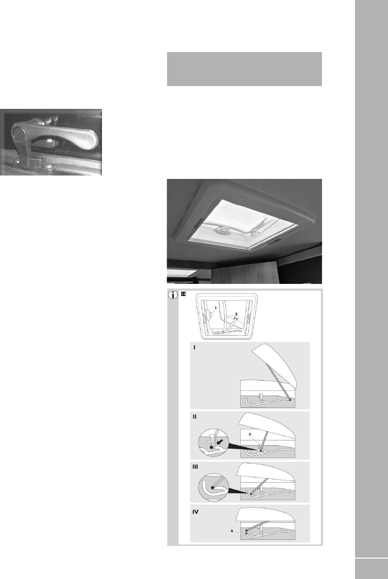
145
FITTED EQUIPEMNT
Inform an approved dealer in case of defects
and malfunctions.
9.16 Escape, Ascari and Voyager cab
roof window
The roof window on the Escape, Ascari and
Voyager is retained in position with window
catches.
The retaining catches are as previously
described on side window catches and can also
be positioned to night vent.
To open the window fully, open all four window
catches and push the window up to the required
opening height. Tighten the knob screw on the
arm of both stays. Close the window if the wind
becomes strong or when travelling.
All roof windows and Skyviews
Before starting off, check the roof light for
damage in the dome (tension cracks) and the
opening mechanism which could arise owing to,
for example, branches and other natural causes.
Do not put weight on the screen.
Do not leave the vehicle with the roof light open
(danger of burglary and water penetration).
Do not open in strong wind, rain or snowfall.
Before opening, remove snow, ice, dirt etc. from
the dome.Malfunctions must be repaired by
an approved dealer at once. Do not use caustic
detergents (danger of tension cracks in the
dome).
Before setting off close the glazed panel dome
and check the locking mechanism.
Avoid high speed (maximum speed
recommended is 130 km/h). Do not close the
blind more than 2/3 during the day (danger of
heat build up). Before starting off, open the
blind.
Care instructions
Clean the dome with the Seitz acrylic cleaner.
Opaque spots and light scratches on the dome
can be removed with the Seitz Acrylic Polish and
the Seitz Special Polishing cloth.
Use talcum powder regulary (4 times yearly) to
care for the rubber seals.
Clean the blinds only with water and mild soap
suds or a vacuum cleaner.
iNote: The guarantee becomes null and
void if the care and safety instructions are not
followed.
9.17 Roof lights
When opening the roof lights, care must be
taken to release the locking mechanism as the
unit is raised.
Roof lights must be fully closed when driving.
Roof lights provide essential fixed levels of
ventilation.
Dometic Mini Heki

146
FITTED EQUIPEMNT
Opening and closing the Mini Heki
Press the release button (1) and open the roof
hood with the bracket at the same time (2).
Opening the roof light completely
Slide the bracket (2) into the I position.
Opening the roof light to the half-way position
Slide the bracket (2) into the II position.
You can push down the sliders (3) on the left and
right to lock it.
Opening the roof light to the ventilation
position
Slide the bracket (2) into the Ill position.
Closing the roof light
Slide the bracket (2) into the IV position.
Guide the bracket (2)with slight pressure to
the left and right via the catches (4), so that the
roof hood is locked and the bracket (2) is on the
release button (1)
Mini and Micro Heki rooflight
(when fitted)
To open depress the button (Fig. A).
Pull the bar down and forwards (Fig. B).
By pushing the bar in to the marked rest
positions (Fig. C).
Two extra opening angles apart from the one in
which the dome is fully opened can be chosen.
The intermediate position can be fixed with a
slide marked with the arrows. Care should be
taken to ensure the dome is closed and locked
for transit with the bar located behind the
locking button (Fig. D).
The blind flynet operate together and engage via
the clips in the bar, then slide to gain the desired
blackout or ventilation (Fig. E).

147
FITTED EQUIPEMNT
Midi Heki
Opening the Dome
Intermediate position for the dome
By pushing the bar into the marked rest position,
two extra opening angles, apart from the one in
which the dome is fully opened, can be chosen.
Closing the Dome (drive and rest position)
Push the bar with both hands on the right and
the left side in such a way that the hook bolt
1. The dome on the left and the right side and
the bar lies on the push button
2. Check if the dome is locked.
WARNING: The retaining catches are
designed to hold the skylight open to the
selected position. In gusty or windy conditions
the Skylight should be closed to prevent it
from being blown fully open or slamming shut.

148
FITTED EQUIPEMNT
With crank
To open, rotate the crank until a resistance is
noticeable during the operation.
To close, reverse the operation and then check if
locked into position
Electric version
To open, push button until desired position is
reached or the electric motor switches off.
To close, reverse the operation and then check if
locked into position.Care instructions:
Care instructions:
Please clean the acrylic panes with the Seitz
Acrylic Cleaner.
Stains and light scratches on the acrylic pane
can be removed by using the Seitz Acrylic Polish
and the Seitz special polishing cloth.
Use talcum powder (4 times yearly) to care for
the rubber seals
Clean the blinds only with water and mild soap
suds
The guarantee becomes null and void if these
instructions are not followed.Omnistep single
step (where fitted)
MPK Rooflight
(when fitted)
VisionStar M pro ll
Operation
To open the rooflight, both pleated blinds must
be open.
Grip the crossbar in the middle and turn it
towards the opening side. Now the rooflight
can be opened by pushing the crossbar. As
soon as you release the crossbar the opening
mechanism snaps into this position.
To close the rooflight, turn it again and push it
back in the opposite direction. When the end
position is reached, the rooflight is locked
automatically.
WARNING:
• Keep the pleated blinds open while driving
to avoid driving noise and damage from the
airstream.
• To avoid heat accumulation do not close
blind completely during the day. Open both
pleats when not using the vehicle.
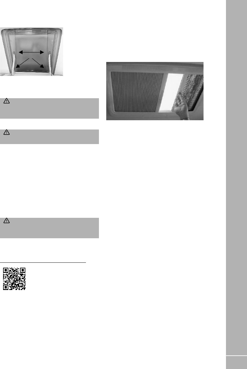
149
FITTED EQUIPEMNT
Cleaning
For easier cleaning , the dome can be removed
from the inner frame by releasing the four
plastic split pins.
WARNING:Do not loosen any screws that
are used to fasten the dome or the opening
mechanism.
Use only clear water and a soft sponge.
WARNING:Solvents may attack the plastic
and make it brittle.
After cleaning, maintain the sliding surfaces
with a thin layer of Vaseline or WD40.
This makes the extension mechanism glide
more easily. The rubber seals can be maintained
with talcum powder.
Pay attention that the pins positively click into
the locked position when re-installing the dome.
The lever arm pins should be re-installed with
the flat side towards the dome.
Clean the pleated blinds with a soft brush, dry
cloth or feather duster.
WARNING: We strongly advise against wet
cleaning, as this can damage the insect screen
and blackout pleated blind.
Warranty
The legal warranty applies.
https://www.mpk-kierspe.de/Downloads
Care instructions:
The rooflight should only be washed by hand,
using a sponge with plenty of clean water
to avoid scratching. Caustic detergents and
solvents may attack the plastic and make it
brittle or disintegrate.
Heki care instructions
Clean the blind only with a damp sponge. Clean
on a regular basis to avoid dust/ dirt particle
build up as this can damage the blind material.
Use only water or with mild suds or a vacuum
cleaner.
In order to avoid material fatigue, do not leave
the flynet closed for a long time.
Roof light blind and flyscreen
The blind and flyscreen operate independently
of each other and are engaged by connecting to
each other and sliding.
Safety precautions:
1. Repairs should be carried out only by trained
personnel.
2. Inform an approved dealer in case of defects
and malfunctions.
3. Before starting off, check the rooflight for
damage in the acrylic dome (tension cracks)
and the winding mechanism which could
arise owing to, for example, branches and
other natural causes.
4. Do not step on the acrylic dome.
5. Close the roof light before starting off (check
whether it is locked).
6. Do not leave the vehicle with the rooflight
open (danger of burglary or from rain).
7. Do not open in strong wind or rain.
8. Before opening, remove snow, ice, dirt, etc.
from the acrylic dome.
9. Malfunctions are to be repaired by an
approved dealer at once.
10. Do not use caustic detergents (danger of
tension cracks in the acrylic dome).
11. Do not operate whilst the vehicle is moving.
Midi-Heki rooflight

150
FITTED EQUIPEMNT
9.18 Omni-vent
(when fitted)
To open the roof cover turn the knob in the
Omni-vent surround clockwise. Turn anti-
clockwise to lower the cover.
CAUTION: The lid must always be closed
when travelling.
Fan operation
The fan is turned on by touching the on/off soft
touch button S2. The middle LED light lights up
and the ventilator starts in comfort mode, this is
the lowest speed (extract). See fig 18.
By pushing on the switch S1 (extract) or S3
(intake), the airflow can be adjusted in 6 steps.
See table below.
*MIN = 3,7 m3/min (2 W - 0,17 A)
*MAX = 24 m3/min (86 W - 7,20 A)
In order to save the battery, the speed drops
from position 6 to the lowest position after one
hour of use.
• It is possible to allow the ventilator to work
for 5 minutes on the highest speed (boost).
To do this push for 3 seconds on the button S1
(extraction) or S2 (intake). After 5 minutes the
ventilator returns to its previous speed setting.
See table below.
For reasons of security, the ventilator, the
ventilator stops when the tension is too high
(19,5 V) or too low (11,1 V) or when the fan is
blocked. For trouble shooting see fig 21.
Maintenance
The ventilator grid can be removed for cleaning.
Also the mosquito screen can be taken out for
cleaning.

151
FITTED EQUIPEMNT
9.19 Omni step single step (where
fitted)
When an Omni step is present, depending on
specification, your motorhome is fitted with
either a manual or electrically operated step.
Manual operation
When a manual step is fitted, it is operated by
manually pulling out or pushing in the step to the
desired position.
Electric Operation
The OMNISTEP is operated by the lever switch.
Important: when extending the step, hold the
switch until the step is completely extended.
Never mount the step if retracted of if not fully
extended, because then the blocking is not
working and the motor can be damaged.
Check if the step is retracted before departure.
Maintenance
Dirt and frost can prevent the step from
operating properly. In this case the moving parts
should be cleaned or defrosted.
All points of movement are layered in
maintenance-free bearings.
In case of electrical failure
If the step does not retract by motor: Loosen the
square connection according to fig. 5 (actions
1, 2 and 3), push the footboard in (4) and tie it to
the frame.
Current drawn
5 A. When fully extended or retracted: 14-18 A
Fig. 4
Fig. 5
9.20 Thule T4200 / 8000 Omnistor
Awning
• For the mounting height of the bottom
mounting brackets ask your dealer.
• An awning is a sun and not an all-weather
protection. The awning should be closed in
case of storm, snow or heavy rain fall (avoid
formation of a water pocket)

152
FITTED EQUIPEMNT

153
FITTED EQUIPEMNT
9.21 Reverse Camera System
Depending on the specification of your
motorhome, a reverse camera system may be
installed. This uses a single or twin lens camera
system mounted at high level on the rear of the
motorhome.
The camera, or cameras, will be connected to
either
1. An LCD screen which forms part of the
windscreen mounted rear view mirror (Fiat
based motorhomes).
2. A dashboard mounted screen (Ford based
motorhomes)
The reverse camera system is powered when
the vehicle engine is running.
Single lens camera system
The single lens camera is mounted at high
level on the rear of the motorhome. While the
engine is running, the image from the camera
can be displayed using the controls on either
the rear view mirror with LCD screen (Fiat),
or dashboard mounted screen (Ford). If
Reverse gear is selected, the relevant screen
will automatically display the image from the
camera.
Twin lens camera system
Two cameras are mounted at high level on
the rear of the motorhome. While the engine
is running, the image from either camera can
be displayed using the controls on either the
rear view mirror with LCD screen (Fiat), or
dashboard mounted screen (Ford). If Reverse
gear is selected, the relevant screen will
automatically display the image from the close
range camera.
Use of cameras
The rear view camera image may be distracting
or disorientating to some drivers and as such
extra care and awareness must be observed
at all times when using the camera. When
reversing a responsible adult should assist
in guiding the driver into confined spaces
particularly where obstacles or pedestrians may
be present or when visibility or lighting levels
are reduced.
The mandatory required rear view door mirrors
must be maintained and used as the primary
rear visibility aid.
The image quality available from the cameras
can be affected by dirt, road spray, rain droplets,
snow and ice and as such the camera lens will
require regular inspection and cleaning. Image
quality will be reduced at night-time or by bright
lights shone in low level lighting conditions.

154
FITTED EQUIPEMNT
Reverse Sensor System
If a reverse sensor system is fitted to your
motorhome, this will use a row of sensors
fitted at low level on the motorhome, to detect
obstacles. The system will automatically switch
on when Reverse gear is selected.
A buzzer located close to the driver’s seat
(within a bed base) will then sound when an
obstacle has been detected and is close to the
rear of the motorhome. An intermittent tone
indicates an obstacle at the maximum distance
of the sensors range, and the time interval
between tones will reduce as the distance to the
obstacle reduces, until a constant tone is heard.
Please consider that the distance is measured
from the rear bumper of the motorhome – if
an accessory such as a cycle rack is added, the
driver must take into account the additional
clearance required beyond the bumper, when
reversing toward an obstacle.
If a tow bar is installed, this should include a
facility to disable the reverse sensor system
when a trailer is connected. A tow bar
installation featuring this facility can be installed
by your Swift Group dealer.
There is a volume control on the buzzer with
three settings ON, LOW and OFF.
9.22 Cycle racks
The Swift Group allows the fitment of a two
cycle rack carrier and we have made provision
for this pre positioned mounting rails fitted to
the rear of your motorhome.
These are spaced at various heights as shown
on the table on the previous page.
The Swift Group only recommends a Thule cycle
rack which will conveniently clip in to the pre
installed mounting rail. The maxiumum weight
which can be mounted on the carrier is 50kg.
Please be aware a cycle rack can not be fitted
onto a model where there is a rear escape
window. Contact your dealer for clarification if
your van has a rear window.
Other lifting variants are also available. Please
review with your dealer and Thule for the
available options.
Thule Bike carrier type Thule Excellent
standard version
Thule Elite G2
standard version
Thule Sport G2
standard version
6 Thule reference 309821 306560 307126
Capacity (# bikes) 2+1+1 2+1+1 2+1
Max load (kg) 50 50 50
Max bike weight (kg) 30 30 19
Range Models
Edge
All
✓ ✓ ✓
Ascari
All
✓ ✓ ✓
Escape &
Voyager
All (except 674)
✓ ✓ ✓
Kon-Tiki
All (except 774, 874, 984
and 994)
✓ ✓ ✓
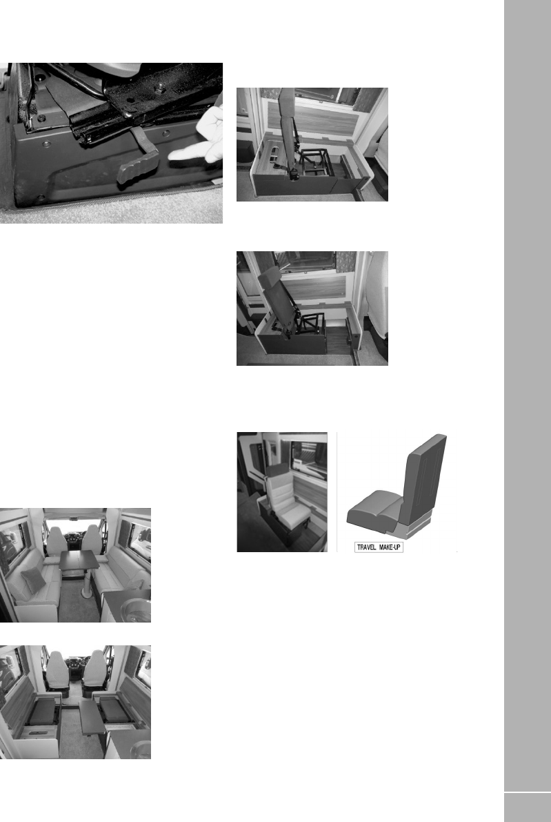
155
FITTED EQUIPEMNT
9.23 Seat swivel (Driver/Passenger)
To turn the swivel, slide the BLACK lever
rearwards and adjust to the required angle.
Before driving off ensure the locking mechanism
is fully secure.
9.24 Heated seats
Your motorhome may be fitted with heated
driver and passenger seats in the Fiat cab area.
For further details of the operation of these
seats, please see the Fiat base vehicle manual.
9.25 Side lockers
Some models are provided with exterior access
locker doors. These are suitable for storing
external equipment.
9.26 Aguti Smart Lounge (Escape,
Voyager and Kon-Tiki)
The front of the Escape, Voyager and Kon-Tiki
models, includes the Aguti Smart Lounge with
fold-up travelling seats.
The lounge in daytime position
Remove all the cushions. Fold away and lower
the table to the bottom position. Slide the table
top to rear to allow access in to the seat.
Turn the handle on the side of the seat and
lift the seat backrest to the upright travelling
position. Repeat on the other side of the van.
Open the front flap by disengaging the turn
button catch and retain open by ensuring
the magnetic catch is located on to the metal
support frame.
Place the infill make-up cushion on the seat
base hard up to the seat back. Place the seat
base cushion onto the seat base ensuring that it
overlaps the infill make-up cushion and that the
Velcro strips engage.
Separate the two halves of the backrest cushion
by peeling apart the Velcro strips and place the
thicker section against the seat backrest. Route
the seatbelt over the top of the backrest cushion
and pull out the seatbelt buckle from the base
of the seat.
Safely store away all the remaining cushions
ready for travel.

156
FITTED EQUIPEMNT
To return to the lounge set up the process is
reversed.
When folding away the travelling seat ensure
the seat is returned to its horizontal position.
Do not rotate past the horizontal.
9.27 Bunk and luton bed safety
Where the sleeping surface is over one metre
above floor level the following notices apply.
WARNING: Always ensure safety boards
are located before entering the bunk.
WARNING: Use upper bunks for sleeping
only, with the provided protection against fall
out in position.
WARNING: Care shall be taken against the
risk of fall out when the upper bunks are being
used by children, especially under 6 years of
age, these bunks are not suitable for use by
infants without supervision.
Layouts with an over-cab bed (luton bed),
access may be restricted when the lower bed
(model specific) is fully extended at night time.
9.28 Powered Bed Mechanism (model
specific)
If fitted to your motorhome, the bed control
panel will be positioned next to the main control
panel located above the habitation entrance
door.
Control Panel Operation
Activate the panel by inserting the supplied key
and turning to the ‘ON’ position. To raise or lower
the bed, press the corresponding arrow; UP
(arrow up), DOWN (arrow down).
iNote: The bed can only be operated when
the engine ignition is turned off.
The bed will continue to move while the switch
is being pressed. It will stop either when the
button is released, or the pre-set stop position
is reached or the end of the stroke position is
reached.
Before lowering, unfasten the safety belts
and ensure the bunk net catches have been
released.
After raising, fasten the safety belts to secure
the bed for transit. Ensure the bed is at the
highest position before fastening the belts. The
safety belts must always be fastened when the
vehicle is in transit.
When the bed is not in use turn the key to the
‘OFF’ position and remove the key to deactivate
the control panel.
WARNING: The bed operating mechanism
should only be operated by a responsible
adult. Take care to ensure that all persons,
pets and loose items are clear of the top and
underside of the bed before operating the
lifting mechanism. Do not operate the lifting
mechanism with a person or heavy object on
the bed. Always remove the key when the bed
lifting mechanism is not in use.
WARNING: Do not touch the lifting system
while the bed is being operated. Safety straps
must always be fastened when performing
maintenance on the lifting system.

157
FITTED EQUIPEMNT
Manual Operation
In the event of power failure or an emergency
the bed can be operated manually. To access
the motor a Pozidriv screw driver is required to
remove the screws on the access panel located
behind the locker door under the bed. A 5mm
Allen key is also required to operate the motor.
Insert the Allen key into the motor as indicated
in the diagram and turn to lift or lower the bed
as required.
WARNING: Always ensure the power is
disconnected before performing any operation
on the bed lifting system.
Care points
Care must be taken to remove obstructions
which will restrict the full range of movement of
the motorised drop-down bed, in particular the
safety belts and bunk net catches. If an object is
left in the way when the bed is being lowered the
motor will continue to run unwinding the belts. If
this occurs, immediately stop the operation and
remove the obstruction. Once the obstruction is
removed raise the bed to re-tension the belts.
Once the belts have been re-tensioned the bed
can be lowered again.
WARNING: (ASCARI):
Do not use the hob unless the bed is lifted to
the highest stowage position.
9.29 Lippert Rise and Fall Island Bed
(Kon-Tiki)
WARNING: Before using the bed always
ensure the safety locking pin is inserted into
the use position (fig.a).
On some layouts we have the facility to increase
the garage storage area under the rear Island
Bed. The bed can be raised or lowered in order
to store and remove objects from the storage
compartment.
To adjust the height of the bed insert the crank
handle into the winding mechanism located
underneath the bed in the garage area. It can
be accessed through the offside garage door.
Ensure there is nothing obstructing the path of
the bed and no excess weight on top of the bed
before moving.
To allow the bed to move, the safety locking pin
must be extracted first (fig. b). Then turn the
crank handle clockwise to raise the bed height
or anti-clockwise to lower the bed height. When
the required height is reached insert the safety
locking pin (fig. a) and remove the crank handle.
WARNING: Before using the bed always
ensure the safety locking pin is inserted into
the use position (fig.a).

158
FITTED EQUIPEMNT
9.30 Tables
iNote: The free standing table legs have
a positive locking mechanism. Care must be
taken to ensure that, when folded, the leg
which is closed first locks into the second
position.
When engaging legs in down position the
mechanism must be positively locked down.
WARNING: When erecting the free
standing table, be careful to avoid trapping
fingers.
Mapa Electric Telescopic Table leg
iNote: Some layouts have a folding table
that incorporates an extension leaf to support
the table once extended. Slide the extension
out before unfolding the table top in order to
support it.
The electric retractable table is controlled by
a switch on the kitchen pattress. The table top
unfolds and has the ability to slide and rotate in
to the required position
Ensuring there are no objects blocking its path
and with the table top folded away in its storage
position, press the table power switch (located
on the kitchen pattress) to the up position and
hold until the desired height is reached.
Pull out the metal support arm from under the
table and unfold the table leaf.
WARNING:Ensure the leaf support is
pulled out, before unfolding the table.
To rotate and slide the table top, lift the lever
underneath the table and move to the desired
position.
The storage of the table is the reverse of the
above.
WARNING:When travelling the table must
be stowed in the lowest position. The table will
not function with the engine running.
WARNING:Should the table be forced to
move when it is obstructed by something, the
fuse may blow and the table will be unable to
move. The fuse is located next to the switch in
the Kitchen pattress.
Table storage
Tables stored in the table storage compartment
must be securely clipped into place whilst in
transit.
To avoid damage care must be taken when
removing tables from their stored position.
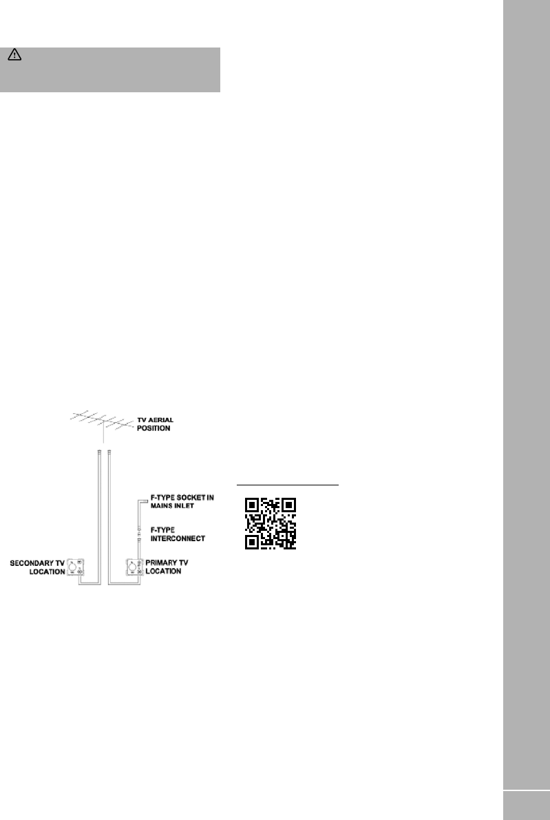
159
FITTED EQUIPEMNT
WARNING: All non-fixed tables must
be stowed in the storage position when the
vehicle is moving.
9.31 Care of laminate tops, tables,
furniture and doors
Do not use abrasives, chemically treated cloths
or aggressive detergents as these may cause
damage
Do not place hot objects on laminated surfaces
i.e. tops, tables. Any temperatures 70°C and over
will cause permanent damage.
Clean worktop surfaces, furniture and door
fascias with a soft, slightly damp cloth, dry off
with a soft cloth.
9.32 TV inlet
Depending on specification, the motorhome
may be fitted with an external co-ax connection
and/or a roof mounted TV aerial. When fitted,
the external co-ax connection point will be
within the mains inlet enclosure.
Co-ax connection point within the mains Inlet
enclosure
A short co-ax lead featuring a screw on co-ax
connection will be present behind the Blue
mains inlet connector. A co-ax cable will be
fitted and connected within the motorhome,
from the back of this connection, to the primary
TV position within the motorhome.
At the same time, further co-ax cable or cables
will be fitted which route from the TV aerial
position (i.e. within the wardrobe) to each of the
TV positions within the motorhomes.
The primary TV position will feature a socket
marked 12v, TV, and SAT. The co-ax from the
external connection point will route to the socket
output marked SAT, whilst the co-ax from the TV
aerial will route to the socket output marked TV.
At any secondary TV positions (if present) co-ax
from the TV aerial will be fitted, and routed to
the socket output marked TV.
An external TV aerial or site TV feed can be
connected to the external connection point;
signals from that connection will then be
available at the primary TV position within
the motorhome. As the connections are of the
screw-on type, it is also possible to use this
co-ax to route from an external satellite dish,
for instance a tripod mounted dish, to a satellite
receiver.
9.33 Status 570 Digital antenna
system
Travelling
Do not travel:
• with the antenna raised
• with the antenna set for vertical signals
To reduce the possibility of damage when
travelling, point the antenna backwards.
The RED SPOT on the bottom of the mast
indicates the front of the Antenna.
Your motorhome may be fitted with a Status
570 TV aerial. Please read the user instructions
for the TV aerial, which are available from the
following location:
https://bit.ly/3bFoq0L
If you are unable to view the documents on line,
please contact the supplier, your dealer or Swift
for an electronic or paper copy.
After performing any of the ‘Actions’ above you
must re-tune your TV.

160
FITTED EQUIPEMNT
9.34 TV Brackets
In some models a bulkhead mounted bracket is
supplied to mount the TV on. Whilst the bracket
has a travel lock it is good practise to unclip
the TV from the bracket and store securley for
transit.
9.35 Motorhome Wifi (where fitted)
In some models, a 3G/4G/5G antenna is pre-
fitted, which is connected to a MiFi (My Wifi)
device. This system connects to the cellular
network, and provides a Wifi connection inside
your motorhome for up to 10 devices to connect
to.
Please check with your dealer whether the MiFi
device is fully installed in your motorhome, and
whether the SIM card supplied with the device
has been pre-installed. The position within the
motorhome is layout specific, but typically in
a wardrobe or in a cupboard above a fridge/
freezer.
Once the SIM card is installed and components
are connected, basic operation is as follows:
• Turn on the power to the device, using the
switch on the base of the unit, at the left hand
side. A red LED will illuminate, and a charging
/ battery symbol will appear in the display on
the front of the unit.
• Press the power button on the front of the
unit. The display will change while the device
starts, and once the unit is ready, a network
name and passkey will appear on that display.
• Search for Wifi on your mobile phone / tablet
/ laptop, looking for the network name as
displayed on the device. Connect, and when
prompted for the passkey/password, use the
code as displayed on the screen.
Complete user instructions, including how to fit
the SIM card and mount and connect the MIFI
device if still required, can be located at the
address below. Please read these instructions
before using the system.
http://www.motorhomewifi.com/swift/
If you are unable to view the documents on line,
please contact the supplier, your dealer or Swift
for an electronic or paper copy.
9.36 Cab Radios
Fiat based motorhomes
For full details of the features within the Fiat
entertainment system, please see the paper
copy literature supplied with your vehicle.
The Fiat radio antenna is housed within the
passenger wing mirror. Any issues with your
radio reception should be referred back to your
Fiat dealer.
While specifications are subject to change,
power to the Fiat entertainment system is
typically turned OFF 20 minutes after the vehicle
ignition is switched off.
It is possible to fit an aftermarket radio to the
base vehicle, customers should note this may
affect steering wheel controls and increase
power consumption
Ford based motorhomes
For full details of the Zenec Xzent F-285
entertaiment system, please see paper copy
literature supplied with your vehicle.
Power to the Xzent unit will be switched OFF,
when the vehicle ignition is switched OFF.
An additional switch is located forward of the
Xzent unit on the dashboard to supply power to
the radio which defaults to the leisure battery
as its primary source of power with the ignition
switched off.

161
FITTED EQUIPEMNT
9.37 Shower
When using the shower, always ensure that the
shower door is fully closed thus avoiding water
spray on unprotected areas.
Trigger head shower
• Squeeze trigger to release water. Release
trigger to stop. Twist trigger up to gain
permanent water flow, lower to stop.
• Orbit shower heads are also provided with a
button at the side of the head to allow users to
control the flow.
• Care should be taken as water may become
hot temporarily when switched on until it
mixes and regulates.
• Small children should be surpervised at all
times when using the shower.
• We recommend unfastening the trigger
shower head before travelling and storing
safely to prevent it becoming detached whilst
travelling.
9.38 Motorhomes with external BBQ
point
Models equipped with an external barbeque
point can be used to power any gas appliance
suitable for the gas used in the motorhome,
at the working pressure shown on the label
in the barbeque outlet box. Please note when
using the outlet that the fitted regulator will
allow a maximum of 1.5kg per hour of gas to
be taken from the gas bottle. Therefore the
consumption of gas from both the appliances
within the motorhome and the appliance
connected to the barbeque point cannot exceed
a total of 1.5kg per hour at any one time. If you
are in any doubt please consult your dealer for
advice. To use point proceed as follows.
When external gas equipment is being
connected, the operating pressure of the gas
supply of 30 or 50 mbar must correspond with
the operating pressure of the equipment that is
being connected (see data plate).
The plug-in connection can only be made if the
quick-acting valve is closed. The safety locking
mechanism can be released by sliding back the
coupling sleeve.
The coupling K-valve is designed such that the
quick-acting valve can only be opened if the
connection is being made via the plug-in
connection. The connection is made by inserting
the plug-in connection into the safety coupling.
This operation can be carried out using one
hand. After uncoupling the equipment, seal off
the valve opening using the protection cap.
iNote: The external gas socket is only
suitable for removing gas, not for feeding gas
into the gas system.

162
FITTED EQUIPEMNT
WARNING: Care should be taken when
using the external barbeque point. Never
barbeque next to an awning or tent.
WARNING: The barbeque point should
only be used as an outlet point for gas, never
connect a gas bottle direct to the outlet.
9.39 The External Shower Point
The external shower point if fitted, will be
supplied with a separate shower head and hose
assembly.
To connect the shower, simply align the plug
with the socket and push into position.
To remove, pull the lower trigger and pull the
plug from the socket.
9.40 Colour reference
The colour codes for touch ups or resprays for
Fiat cabs are Fiat White 249, Lanzarote Grey
385, Metallic Iron Grey 691, Metallic Black 632
and Expedition Grey 676. For the Ford cab the
colour is Magnetic Grey FM6EWHA. The white
Swift coach built habitational body components
are Fiat White 249.
Please be aware that colours can fade over
time, and therefore, if the vehicle is more than
a few years old, it is suggested a colour match
be obtained. If these are small areas that do not
require a full respray of the entire panel you can
use an over the counter polishing compound
to return the original finish. We would always
recommend that an inconspicuous area of the
motorhome is tested beforehand.

163
10. Maintenance
10.1 Vehicle modifications & non-standard parts . . . . . . . . . . . . . . . . . . . . . . . 164
10.2 Motorhome exterior . . . . . . . . . . . . . . . . . . . . . . . . . . . . . . . . . . . . . . . . . . . . . . 164
10.3 Condensation . . . . . . . . . . . . . . . . . . . . . . . . . . . . . . . . . . . . . . . . . . . . . . . . . . . . 164
10.4 Changing Exterior Bulbs . . . . . . . . . . . . . . . . . . . . . . . . . . . . . . . . . . . . . . . . . . 166
10.5 Motorhome Interior Care . . . . . . . . . . . . . . . . . . . . . . . . . . . . . . . . . . . . . . . . . 166
10.6 Swift Shield Fabric (model specific) . . . . . . . . . . . . . . . . . . . . . . . . . . . . . . . 167
10.7 LED Replacement . . . . . . . . . . . . . . . . . . . . . . . . . . . . . . . . . . . . . . . . . . . . . . . . 168
10.8 Winterisation . . . . . . . . . . . . . . . . . . . . . . . . . . . . . . . . . . . . . . . . . . . . . . . . . . . . 169
10.9 Chassis and rear axle . . . . . . . . . . . . . . . . . . . . . . . . . . . . . . . . . . . . . . . . . . . . . 171
10.10 AL-KO exhaust system . . . . . . . . . . . . . . . . . . . . . . . . . . . . . . . . . . . . . . . . . . . 171
10.11 Caring for the environment . . . . . . . . . . . . . . . . . . . . . . . . . . . . . . . . . . . . . . 171
MAINTENANCE

164
MAINTENANCE
10.1 Vehicle modifications & non-
standard parts
As the owner of a Swift Group Product, you are
able to make any modifications you wish, either
by yourself or through a dealer, without affecting
the Swift 3/6 Year Warranty.
However, please be aware that any issues,
resulting directly or indirectly, from a
modification or fitment of a non-standard
part, will not be covered by The Swift Group
Warranty.
WD40 is not recommended for external or
internal use
WD40 attacks paintwork and sealants.
If a lubricant is required for Interior hinges,
Sliding door tracks, Exterior door hinges,
Plastic tracking etc. We recommend “Ambersil
40+” this is readily available from most DIY/
Automotive spare part retailers
Before carrying out any DIY work within the
warranty period (3/6) years please check with
your Swift Group dealer.
10.2 Motorhome exterior
Cleaning
1. Wash the motorhome regularly with mild
detergent. Rinse with cold water and leather
off.
2. For better protection a similar coloured good
quality car wax may be applied.
For sealed areas a mild soap is the best way to
clean without affecting the sealant.
Acid or alkaline based cleaners or solvents
should not be used.
WARNING: Under no circumstances use
any abrasive cleaning agents or solvents on
the exterior. Do not wash your motorhome
with a high pressure washer as these can
permanently damage the seals of your
motorhome.Care should be taken as the
silicon in some polishes can attack the rubber
used on the exterior for seals and gaskets.
Acrylic Windows
Wash windows carefully, as you would with the
paintwork of your car, do not scrub windows
prior to removing surface dirt and film with a
hose pipe - trapped dirt could cause scratching.
Wash with a solution of warm soapy water,
windows can then be dried off with a leather
shammy.
Small scratches can be removed, consult your
dealer.
Catches and stays do not require any special
attention or lubrication.
Acrylic (Plastic) Window Cleaning
The material used to produce most caravan and
motorhome windows is acrylic plastic. While
the acrylic used is very durable, it is able to be
scratched with relative ease and therefore, care
must be taken when clearing your vehicle not to
use aggressive clearing products. Equally, care
should be taken when using a drying cloth that it
is clean and free from grit.
10.3 Condensation
What is condensation
Condensation is the process of change of water
from its gaseous form (water vapour) into
liquid water when it comes into contact with a
surface that is cold. Condensation generally
occurs when warm air cools quickly and loses
its capacity to hold water vapour, and as a result
water vapour condenses to form droplets.
Why condensation occurs
Condensation occurs when warm moist air
meets a cold surface. The level of condensation
will depend upon humidity levels, how moist the
air is and how cold the surfaces are they come
into contact with.

165
MAINTENANCE
If the temperature falls below the dew point
temperature, it is quite normal for condensation
to occur on any material within the motorhome
that is cold, for example the external walls,
plastic windows etc.
When condensation occurs
Condensation occurs usually in winter months,
because ambient temperatures are colder
(leading to cold surfaces) and windows and roof
vents are opened less so the moist air cannot
escape.
Where condensation occurs
Condensation will occur where warm moist air
is put into the atmosphere in areas such as in
bathrooms (during showering) and in kitchen
areas (during cooking).
In the enclosed space of a motorhome, the
moist air from the kitchen or bathroom areas
will inevitably transfer to the rest of the vehicle,
which in turn condenses on cold surfaces
leading to visible water droplets. This issue
is compounded by warm moist air being
generated from normal breathing.
Condensation will also form in cold areas where
air movement and ventilation is restricted (e.g.
cupuboards, wardrobes, under beds, etc.)
What is important
It is important to provide ventilation and air
flow, so that warm moist air can escape, or
be externally cooled, and to use the heating
reasonably by not making the motorhome too
warm such that people perspire, as this will only
serve to generate more moist air and therefore
more condensation.
However, in particularly cold periods, where
the external ambient temperatures are low,
condensation may still form on external walls as
the insulation levels may well not be thermally
able to cope with the difference between the
internal and external temperatures.
How can you prevent condensation
Provide ventilation so that moist air can
escape.
a. Good ventilation of the vehicle when cooking
or when drying clothes, footwear or pets
is essential. Observe when windows begin
to show signs of misting and increase
ventilation by opening slightly by 1cm or
opening a roof vent, as these will help, but
keep the habitation door closed as much as
possible to retain heat.
b. If drying damp clothes or towels, open a
window to ventilate the area and allow the
moist air to escape.
c. Try to make sure that the motorhome is
partially heated. It can take a long time for a
cold motorhome to warm up, so it is better to
have a small amount of heat for a long period
than a lot of heat for a short time.
d. After showering, keep the bathroom window
or skylights open, and shut the bathroom
door long enough to dry off the room.
e. In all other areas provide some ventilation.
Fixed ventilation is provided in accordance
with BS EN 721: 1998 this is through
skylights and ‘Heki roof lights’ in the roofs
and from ventilators through the floor
under cookers, doors and in bed boxes. It is
important not to block these.
f. Electrical heating is dryer than gas heating,
and introduces less moisture into the
atmosphere. Do not use additional portable
paraffin or flue-less gas heaters at all.
g. If left unoccupied and unheated for long
periods of time the temperatures can soak
down thermally into the entire product and
become very cold. Whenever possible, put
the heating on at a low level before use by
pre heating in cold weather.
h. Even with reasonable ventilation it is likely
if the temperature is less than 5°C and the
humidity is high that condensation will occur.
Ideally the temperature should be kept about
20°C when occupied.
Too much ventilation in cold weather is
uncomfortable and wastes heat. All that is
needed is a very slightly opened window or
skylights. Opening a skylight or ‘Heki; rooflights
partially or windows opened to about 1cm will
usually be sufficient.

166
Provide reasonable heating
a. Do not use portable paraffin or flueless gas
heaters at all.
b. If drying damp clothes or towels, open a
window enough to ventilate the area and
turn on the electric element of the space
heater but do not hang items over the heater.
c. Try to make sure that all areas are at least
partially heated. Condensation most often
occurs in unheated areas.
d. To prevent condensation, the heat has to
keep room surfaces reasonably warm. It
can take a long time for a cold motorhome
to warm up, so it is better to have a small
amount of heat for a long period than a lot of
heat for a short time.
Motorhomes use only carefully selected
insulation materials but unlike most rooms at
home all walls are exterior walls, so they lose
heat through all walls as well as the roof and
floor.
Even in a well insulated motorhome with
reasonable ventilation, it is likely that during
cold weather (less than 10°C) condensation will
occur. Ideally the temperature should be kept
about 20°C although this is not always possible.
Mould Growth
Any sign of mould growth is an indication of
the presence of moisture and if caused by
condensation gives warning that heating or
ventilation may require improving.
New vehicles
New products take a long time before they are
fully ‘dried out’ because of the moisture in the
materials used during manufacture. While this
is happening extra heat and ventilation will be
required.
Corrosion
Your motorhome has been designed and built
using the corrosion resistant materials (e.g.
GRP (Glass Reinforced Plastic) panels, stainless
steel fixings, hot dip galvanised chassis and
powder coated extrusions), which if looked
after will extend the life and aesthetics of the
product in normal service. In certain conditions,
for example, if sited for extended periods in
close proximity to sea and sand spray, you may
experience premature ageing and/or corrosion
of the vehicle than under normal conditions.
To help prevent this, we advise regular cleaning
and application of a good quality external car
polish. For extended periods (where the vehicle
is not in use), we recommend the use of well
fitted breathable vehicle cover as protection
from harsh coastal elements.
10.4 Changing Exterior Bulbs
Always replace like for like.
The road lights and awning light fitted to the
coachbuilt part of your motorhome are LED and
contain no user serviceable parts, in the event
of a failure or damage the entire light would
need to be replaced. For the road lighting on the
Fiat/Ford base vehicle, please see the Fiat/Ford
handbook supplied as Fiat/Ford specifications
are subject to change.
10.5 Motorhome Interior Care
Follow these guidelines to ensure your
investment is receiving the very best attention.
Side Walls, Roof Lining
A simple wipe over with a damp cloth and a very
mild detergent is all that is needed.
Soft Furnishings
Should be vacuumed occasionally to remove grit
and sand and help to keep its smart appearance
over the lifetime of the upholstery. The
upholstery can be cleaned with a mild, reputable
upholstery cleaner. It is recommended that the
curtains and pelmets are specialist cleaned only.
The foam used
in cushions is manufactured to meet fire
regulations. It requires time to return to its
normal position after prolonged use.
Cupboard Catches
It is advisable to lubricate all cupboard catches,
sliding bolts and hinges from time to time.
We recommend “Ambersil 40+” this is readily
available from most DIY/ Automotive spare part
retailers.
MAINTENANCE

167
MAINTENANCE
Doors
In order to provide customers with the latest
designs of door furniture it is possible, due
to the use of natural wood, that warping may
occur. This should not detract from the correct
functioning of items fitted in the motorhome.
Information
During the normal travelling vehicle vibration
and flexing may cause some of the furniture
doors to become out of alignment.
For your convenience many hinges are
adjustable.
Leather care
Leather furniture, in a normal contract
and domestic environment, requires little
maintenance, although obviously leather in
lighter shades will need more attention.
Regular care of leather does ensure its lasting
quality and some general rules for regular
cleaning and maintenance are:
• Clean the leather with a soft damp cloth taking
care not to soak the leather.
• For a more thorough clean, use the Bridge
of Weir Leather Cleaning and Protection kit
available directly from the distribution centre.
• Do not use saddle soap, wax polishes or spray
polishes.
• Do not use any product or any method
of cleaning not recommended by the
manufacturer.
• Avoid letting any buckles, studs and zips come
into direct contact with the furniture.
• Avoid drying out the leather by taking extra
care where there is heating or an open
fireplace.
iNote: The above cleaning instructions
DO NOT apply to Nubuck Suede or any other
uncoated leather.
10.6 Swift Shield Fabric (model
specific)
The Swift Shield fabric fitted to some Swift
Group products is a luxury stain resistant
durable fabric using Aquaclean® technology.
This is a revolutionary fabric treatment that
allows you to clean stains using water only. This
provides you with simple fabric maintenance in
the minimum amount of time.
Cleaning Instructions
Aquaclean® helps to remove the majority of
household stains (wine, ink, sauce, fat, mud,
chocolate, cream, etc.) in three simple steps:
Remove any excess residue
on the upholstery.
Apply water over the stain,
either directly or using a
damp cloth. Wait a few
seconds.
Press down over the stain
with a damp cloth and
rub gently over the fabric
in circular movements. If
the stain does not come
off completely, repeat the
process as required.
For further details and stain cleaning demo
videos visit the Cleaning Gallery on the
Aquaclean® web site: http://www.aquaclean.
com/ES_en/home.
Aquaclean fabrics cannot accept any
responsibility for misuse of the fabric by
allowing bleach or dissolvent substances
coming into contact with it.

168
MAINTENANCE
Stainless Steel Bowl Care Instructions
After use always remove any plastic bowl or
mat, rinse down the surface and dry with a soft
cloth to prevent spotting. For more stubborn
dirt or grease a non-abrasive multi-purpose
cream cleaner, such as CIF, may be used. To
preserve the appearance of your appliance we
recommend plastic bowls or mats are not stored
in the sink during transit.
The quality of water can affect your bowl's
appearance. If the water has high iron content, a
brown surface stain can form on the bowl giving
the appearance of rust. Additionally, in areas
with a high concentration of minerals, or with
over-softened water, a white film may develop
on the sink. To combat these problems, towel
dry the sink after use, and clean at least once
every week .
Surface scratching will be most noticeable on
highly polished components. These marks are
usually only superficial and can be removed with
a proprietary stainless steel cleaner/polish.
If the surface has a directional polished grain
always clean along the grain and NOT across.
Never use wire wool pads to clean the surface.
Cleaning agents containing bleach should
NOT be left in contact with stainless steel. This
includes many of the new “trigger-dispense”
products and some multi purpose cream
cleaners. Also leaving rubber mats or dishpans
in the sink can lead to surface rust or pitting,
always remove them after use.
Work Surfaces
You should not stand very hot items on any
of the work surfaces, especially models with
polycarbonate moulded sinks and drainers.
Kitchen Equipment
All the thermoplastic parts in these areas have
easy clean surfaces. To ensure long life and to
prevent damage you must not use any cleaning
materials at all and ensure water temperatures
do not exceed 70ºC (putting cold water in first is
suggested). After every use it is essential that
you rinse with clean water only and wipe with a
soft damp cloth. Failure to follow these simple
instructions may result in premature failure
or cracking which will not be covered by any
guarantees (including extended warranties).
Bathroom/Shower
These products should be cleaned immediately
after use. Apply a warm, mild soapy water
solution with a soft cloth and rinse with clean
water immediately. Abrasive materials must
never be used.
Washroom bi-fold doors
• Panels should be cleaned with warm soapy
water and a non-abrasive cloth/sponge.
• An abrasive or aggressive cleaning agent is
never to be used
• A proprietary plastic cleaner Vuplex®, can also
be used. This can be obtained from outlets
such as Amazon, ebay etc.
Furniture
A simple wipe over with a damp cloth should be
all that is required. Polishing with a proprietary
brand of wax polish enhances and maintains
furniture in showroom condition.
Kitchen Drainer and Cutting Board
You should not stand hot items on to the
removable plastic kitchen drainer. To wash use
only warm soapy water, do not use chemicals
and bleach.
Changing interior bulbs / LED Lights
For non LED lights remove the lens or
lampshade to access the bulb.
Always replace like for like
10.7 LED Replacement
In many applications LED lights are fitted which
contain no user serviceable parts. In the unlikely
event of failure of one of theselamps, the entire
lamp will need to be replaced – several types
of LED light are intended for semi-permanent
installations using self adhesive mounts etc,
and dealer assistance may be required should
damage or other need for replacement occur.

169
MAINTENANCE
10.8 Winterisation
The Swift Group recommends the following
winterisation points for customers:
Servicing
Arrange (in advance) the yearly service and
habitation check, if the motorhome's next
service is due while the vehicle is stored.
Plumbing
Water expands as it is frozen, and so trapped
water, when it expands, can damage the tap /
valve /pump or pipe it is trapped within. For this
reason, (in addition to reasons of hygiene), the
water system should be fully drained when not
in use, particularly in colder weather.
• Open both the fresh tank and waste water
tank drain valves (via the control panel above
the entrance door, the switches in the China
Locker or by the manual valve under the skirt
(Edge and Voyager) or remove the bung in the
bottom of the fresh tank (Edge).
• Open the drain valve (yellow handle) next to
water heater, and leave open. See section 7.2.
• Fully open all the taps and shower mixer, move
mixer position to the middle, and leave all taps
in the open position.
• Unscrew the shower head and shower hose,
shake out remaining water and allow water to
drain. It is advised to leave the shower head
and hose disconnected.
• Run pump for a short time, until all water is
expelled.
• After a short while the majority of water will
have left the plumbing system. At this point
however it is still important to ensure that
the pump itself is ‘dry’. During this part of the
winterisation, a suitable absorbent cloth or
container should be used to catch a small
amount of spilled water that will result.
Disconnect the pipe work from the pump by
pulling the blue quick release tabs, at either side
of the pump, at right angles to the pipe work,
then pulling the pipe and connectors from the
pump. See Fig.1 Run the pump for a short while
to expel any remaining water within the pump.
Pull pipe out
Pull quick
release tabs
Fig.1

170
MAINTENANCE
Electrical
If vehicle is being stored while connected to
230v Mains Hook-up:
• Ensure that the leisure battery is connected,
and the leisure battery fuse or fuses are in
place.
• The isolator switch on PSU should be in the
'ON' position, however. the control panel
should be switched 'OFF'.
• If Alde system is installed, there is a frost
protection setting, which can be used. See
Alde user instruction manual.
• Vehicles can be left in this condition for
extended periods, with the charger operating
to maintain the battery. However, periodic
maintenance and inspection is recommended,
this should include the battery condition.
If vehicle is being stored not connected to 230v
Mains Hook-up:
• Charge the leisure battery for 24 hours prior to
placing motorhome in storage.
• Ensure the isolation button on PSU is in the
'OFF' position.
• The battery should not be adversely affected
by winter temperatures but the level of charge
should be maintained to maximise the life span
of the battery. This can be achieved using an
automotive type battery charger as and when
required.
• Disconnect the vehicle battery negative
terminal. Check the charge of the battery
every three months. (See Vehicle Inactivity
section in the Fiat handbook). Alternatively put
the ignition into the 'Isolation Mode'
WARNING: If your motorhome is fitted
with Swift Command Tracker (by Sargent)
which monitors battery voltage. If you plan to
disconnect or remove your leisure battery for
maintenance or external charging, then please
contact the monitoring station before you
remove or disconnect the battery. If a leisure
battery is not fitted, please also contact the
Tracker monitoring station before removing
the mains hook up. The Swift Command
Tracker monitoring station can be contacted
on 0345 6027302 Gas system.
Gas system
• Ensure the gas supply is isolated at the gas
bottle, and ensure that the gas manifold taps
are off.
• Check the age and condition of the high
pressure gas hose and regulator, and replace
if required.
Appliances
Check the battery expiry date on the smoke
alarm and CO detector and replace or remove as
required.
• Ensure the fridge is turned off.
• Clean the inside of the fridge.
• Prop the fridge door open, and if possible,
the internal freezer compartment door for
ventilation.
• Fit fridge vent winter covers (if available).
• Ensure all hob / oven / microwave surfaces
are clean.
• If the motorhome is going to be left connected
to 230v supply while not in use, ensure the
microwave is unplugged.
• Clean the toilet and empty the cassette and
lubricate the seals with an acid free lubricant
such as Thetford High Grade Seal Lubricant.
See Thetford toilet Users manual.
Exterior (Body / Chassis)
• Ensure that all windows, skylights and access
doors are closed and secured.
• Ensure all fixed ventilation points (high and
low) are clear from debris and obstructions.
• Ensure the vehicle is not parked where falling
debris (i.e. leaves, tree sap) could cause
damage.
• Avoid leaving the vehicle parked in soft
ground, long grass or a potential area where
standing water may form.
• Lubricate relevant points on the chassis.

171
MAINTENANCE
Wheels and Tyres
• Do not store in one position with partially
deflated tyres. The tyre walls will suffer
and do present a real danger of blow outs,
especially when travelling at faster speeds
than are allowed in the UK. The wheels
should be turned every couple of weeks.
If you are removing the wheels, follow the
jacking procedure for changing a wheel.
Check your tyres regularly for signs of age and
deterioration, particularly wear, cracking and
blistering. If in doubt consult a reputable tyre
fitter.
• A purpose made cover maybe used, but please
ensure the cover is a good fit, breathable and
securely fitted.
iNote: A poorly fitted cover can rub and
damage the bodywork. Non-breathable
covers will encourage mould to grow.
Interior (Furniture / furnishings)
• Open all lockers and internal doors, to ensure
good circulation.
• Remove cushions and store them in a dry
location or ensure all cushions are placed in a
well ventilated area.
• Close all blinds and curtains. Customers are
reminded to check the tension on blinds after
storage if left closed for long periods.
• Thoroughly ventilate the motorhome by
opening doors or windows periodically.
• Placing water absorbent crystals in the van
during the winter months, will help reduce
moisture levels and mould growth.
• We do not recommend leaving portable
heaters in the van unattended.
Recomissioning the water system
Re-connect the water pump by positioning
the pipe connectors into the pump housing
and pushing the blue tabs into position. it is
advisable, after a period of non-use, to flush
the water system with a sterilising solution
suitable for stainless steel containers and
components. Fill the fresh water tank with water
and sterilising fluid (refer to sterilising fluid
instructions for the amount to use). Turn the
pump on and open all the taps, ensuring that the
water drains away safely to the waste tank.
When the waste tank is full empty the fluid into
a designated waste water area. Re-fill the tank
with fresh water and flush through the system
as described above; repeat this until all traces
of the sterilising fluid have been flushed out.
(See sections 7.3, 7.4 and 7.6)
Prepare the toilet system by adding water and
Thetford fluid to the toilet waste tank.
(See section 9.11)
Appliances
Before starting motor caravanning after
storage, check all gas appliances and electrical
points.
iNote: Preferably not less than once a year,
the electrical installation should be inspected
and tested by a qualified electrician.
After storage it is advisable to air the Motorhome
and clean throughout, especially cooking
appliances and the refrigerator.
Replace the bedding if they were removed for
storage.
WARNING: Always follow the
manufacturers recommended procedures
after use of fitted equipment in the
Motorhome, before storing for any length of
time.
10.9 Chassis and rear axle
Some models are built on a Fiat base vehicle,
the chassis of which has been converted by
AL-KO. This conversion provides a hot dipped
galvanised steel chassis coupled with a wide
track rear axle utilising steel torsion bar
suspension, imparting vastly improved stability
and road holding.
10.10 AL-KO exhaust system
A standard Fiat exhaust system is fitted, utilising
an AL-KO modified tail pipe, available through
your approved dealer. A standard Fiat/Ford
exhaust system is fitted to all other models, with
the addition of a Swift Group tail pipe.
10.11 Caring for the environment
After many years of service you may decide that
your motorhome has become beyond economic
repair and should be disposed of. Please ensure
that you comply with the end of life vehicle
legislation and take it to an authorised treatment
facility where it will be properly dealt with to
minimise any negative environmental impact.
The transaction will be logged at the DVLA,
identifying that you are no longer the owner of
the vehicle.

172
MAINTENANCE

173
11. Useful Information
11.1 Owners club . . . . . . . . . . . . . . . . . . . . . . . . . . . . . . . . . . . . . . . . . . . . . . . . . . . . . 174
11.2 Spares and after sales customer service . . . . . . . . . . . . . . . . . . . . . . . . . . 174
11.3 Repair facilities . . . . . . . . . . . . . . . . . . . . . . . . . . . . . . . . . . . . . . . . . . . . . . . . . . . 174
11.4 Caravan Clubs . . . . . . . . . . . . . . . . . . . . . . . . . . . . . . . . . . . . . . . . . . . . . . . . . . . 175
11.5 Motoring Associations . . . . . . . . . . . . . . . . . . . . . . . . . . . . . . . . . . . . . . . . . . . . 175
11.6 Trade Association . . . . . . . . . . . . . . . . . . . . . . . . . . . . . . . . . . . . . . . . . . . . . . . . 175
11.7 Index . . . . . . . . . . . . . . . . . . . . . . . . . . . . . . . . . . . . . . . . . . . . . . . . . . . . . . . . . . . . 161
11.8 Change of ownership . . . . . . . . . . . . . . . . . . . . . . . . . . . . . . . . . . . . . . . . . . . . . 180
USEFUL INFORMATION

174
USEFUL INFORMATION
11.1 Owners club
The Owners Club is a completely independent
organisation run for the benefit of the
motorhome owners. They have numerous rallies
during the year in various parts of the country.
Apart from the friendliness and companionship
the Club generates it is also actively engaged
in charity work for those less fortunate than
ourselves. The address of the Secretary of the
Owners Club can be obtained from the Swift
Group website.
11.2 Spares and after sales customer
service
A catalogue of spare parts are available through
our Swift Group Dealer Network, from door
catches through to spare wheels. Please note,
all parts enquiries must be directed through
your dealer, as the Swift Group does not operate
a direct retail service.
We endeavour to supply parts for vehicles up
to 8 years old. If the original part is no longer
available your dealer should be able to source a
suitable alternative.
iNote: Please remember to quote chassis
VIN (Vehicle Identification Number) when
ordering any items from your dealer. This can
be found at the bottom of the windscreen, on
the Swift and Ford plates on the passenger cab
door B pillar or on the Fiat plate on front cross
member within the engine compartment.
11.3 Repair facilities
Should you be unfortunate to encounter damage
to your vehicle, we have a number of approved
workshops and dealerships with workshop
facilities to undertake such repairs.
Details of which can be found via our website:
www.swiftgroup.co.uk/find-a-dealer

175
USEFUL INFORMATION
The enjoyment of motorhoming can be greatly
enhanced by membership of one or more of the
various motorhome/caravanning, motoring and
holiday clubs. Here are some useful addresses:
11.4 Caravan Clubs
The Caravan Club,
East Grinstead House, East Grinstead
West Sussex, RH19 IUA
Tel: 01342 326944
www.caravanclub.co.uk
The Camping and Caravanning Club,
Greenfields House,
Westwood Way,
Coventry,
West Midlands.
Tel: 0845 130 7631 or 024 7647 5448
www.campingandcaravanningclub.co.uk
11.5 Motoring Associations
Automobile Association (AA)
Fanum House,
Basingstoke,
Hants. RG1 2EA
Tel: 08705 448866
www.theaa.co.uk
e-mail: customer.serv[email protected]
RAC Motoring Services
RAC Motoring Services
8 Surrey St
Norwich Norfolk NR1 3NG
Tel: 01922 437000
www.rac.co.uk
The Society of Motor Manufacturers and
Traders Limited (SMMT)
Forbes House,
Halkin Street,
London SW1X 7DS
Tel: 020 7235 7000
www.smmt.co.uk
Green Flag
Tel: 0845 246 1557
www.greenflag.com
RBS Insurance
Churchill Court
Westmoreland Road
Bromley
Kent BR1 1DP
Tel: 0800 158 2493
11.6 Trade Association
NCC
Catherine House,
Victoria Road,
Aldershot,
Hampshire, GU11 1SS
Tel: 01252 318251
www.thencc.org.uk
www.motorhomeinfo.co.uk
e-mail: [email protected]
© 2022 SWIFT GROUP LTD

176
INDEX
Index
Symbols
12 Volt DC Fuses . . . . . . . . . . . . . . . . . . . . 81, 104
230V mains electrical equipment power
consumption . . . . . . . . . . . . . . . . . . . . . . . . . . . . . 66
3030 Alde Heating System . . . . . . . . . . . . . . 130
A
Accessory harnessing . . . . . . . . . . . . . . . . . . 116
AC Current Limiter Operation . . . . . . . . . . . . . 94
Acrylic (Plastic) Window Cleaning . . . . . . 142
Additional security . . . . . . . . . . . . . . . . . . . . . . . 42
Advice on towing . . . . . . . . . . . . . . . . . . . . . . . . . 28
Aguti Smart Lounge (Escape, Voyager and Kon-
Tiki) . . . . . . . . . . . . . . . . . . . . . . . . . . . . . . . . . . . 155
Airbag . . . . . . . . . . . . . . . . . . . . . . . . . . . . . . . . . . . 24
Air-conditioning . . . . . . . . . . . . . . . . . . . . . . . . . . 97
Alarm Power Supply . . . . . . . . . . . . . . . . . . . . 116
Alde 3030 Control Panel and Appliance
Instructions . . . . . . . . . . . . . . . . . . . . . . . . . . . . 130
Alde Compact 3030 Boiler . . . . . . . . . . . . . . 130
Alde Zonal Control . . . . . . . . . . . . . . . . . . . . . 131
AL-KO exhaust system . . . . . . . . . . . . . . . . . . 171
All roof windows and Skyviews . . . . . . . . . 145
Annual service/ inspection record . . . . . . . . . 10
Ascari Hob and Oven . . . . . . . . . . . . . . . . . . . 138
Awnings and Tents . . . . . . . . . . . . . . . . . . . 17, 46
Awning Spaces LPG Appliance Exhaust . . . . 62
B
Base Vehicle Warranty . . . . . . . . . . . . . . . . . . . . . 6
Bathroom/Shower . . . . . . . . . . . . . . . . . . . . . 168
Battery Charger . . . . . . . . . . . . . . . . . . . . . 78, 102
Battery replacement . . . . . . . . . . . . . . . . . . . 112
Before moving off . . . . . . . . . . . . . . . . . . . . . . . . 20
Blind Advice . . . . . . . . . . . . . . . . . . . . . . . . . . . 144
Body Shell Warranty . . . . . . . . . . . . . . . . . 6, 7, 9
Boiler / Water System Drain . . . . . . . . . . . . . . . 49
Bottle Replacement Procedure . . . . . . . . . . . 37
Bunk and luton bed safety . . . . . . . . . . . . . . 156
Butane . . . . . . . . . . . . . . . . . . . . . . . . . . . . . . . . . . . 60
Butterfly outlets . . . . . . . . . . . . . . . . . . . . . . . . 125
C
Cab Radios . . . . . . . . . . . . . . . . . . . . . . . . . . . . . 160
Camp sites . . . . . . . . . . . . . . . . . . . . . . . . . . . . . . . 16
Caravan Clubs . . . . . . . . . . . . . . . . . . . . . . . . . 175
Care of laminate tops, tables, furniture and
doors . . . . . . . . . . . . . . . . . . . . . . . . . . . . . . . . . . 159
Care of the microwave . . . . . . . . . . . . . . . . . . 140
Caring for the environment . . . . . . . . . . . . . 171
Cassette Toilet Faults . . . . . . . . . . . . . . . . . . . 141
Central locking . . . . . . . . . . . . . . . . . . . . . . . . . . . 20
Change of ownership . . . . . . . . . . . . . . . . . 9, 180
Changing a gas cylinder . . . . . . . . . . . . . . . . . . 61
Changing Exterior Bulbs . . . . . . . . . . . . . . . . 166
Changing interior bulbs / LED Lights . . . . 168
Charging from Solar Panels . . . . . . . . . . . . . 115
Chassis and rear axle . . . . . . . . . . . . . . . . . . . 171
Children . . . . . . . . . . . . . . . . . . . . . . . . . . . . . . . . . 40
Child seats . . . . . . . . . . . . . . . . . . . . . . . . . . . . . . . 23
Cleaning water system . . . . . . . . . . . . . . . . . . . 51
CO alarm . . . . . . . . . . . . . . . . . . . . . . . . . . . . . . . . 41
Coastal code . . . . . . . . . . . . . . . . . . . . . . . . . . . . . 18
Code of conduct . . . . . . . . . . . . . . . . . . . . . . . . . . 16
Combi 4 Gas/Electric and Combi 6 Gas/ Electric
appliances . . . . . . . . . . . . . . . . . . . . . . . . . . . . . 126
Common Fault Table . . . . . . . . . . . . . . . . 82, 105
Condensation . . . . . . . . . . . . . . . . . . . . . . . . . . 164
Connecting to the Mains 230V supply and Safety
checks . . . . . . . . . . . . . . . . . . . . . . . . . . . . . . . 71, 88
Conventional Load . . . . . . . . . . . . . . . . . . . . . . . 21
Cooker 3 burner with combined grill and oven /
cooker 3 burner + electric hotplate with separate
grill and oven . . . . . . . . . . . . . . . . . . . . . . . . . . 132
Cooking Guidelines . . . . . . . . . . . . . . . . . . . . . 135
Corrosion . . . . . . . . . . . . . . . . . . . . . . . . . . . . . . 166
CP Plus Controller . . . . . . . . . . . . . . . . . . . . . . 126
Cruise control . . . . . . . . . . . . . . . . . . . . . . . . . . . . 33
Cupboard Catches . . . . . . . . . . . . . . . . . . . . . 166
Cycle racks . . . . . . . . . . . . . . . . . . . . . . . . . . . . 154
Cylinder compartment . . . . . . . . . . . . . . . . . . . 60
D
Dedicated travelling passenger seating . . . 23
Dogs and other Pets . . . . . . . . . . . . . . . . . . . . . . 16
Dometic absorption refrigerator . . . . . . . . 131

177
INDEX
Doors . . . . . . . . . . . . . . . . . . . . . . . . . . . . . . . . . . 167
Driving . . . . . . . . . . . . . . . . . . . . . . . . . . . . . . . . . . 17
Driving licence . . . . . . . . . . . . . . . . . . . . . . . . . . . 28
E
EC400 + Control Panel Component Layout . 72
EC400+ Motorhome Power Control System 70
EC800 Air-conditioning screen . . . . . . . . . . . . 97
EC800 Bluetooth Pairing & Other Controls . 97
EC800 Control Panel . . . . . . . . . . . . . . . . . . . . . 89
EC800 Heating Controls . . . . . . . . . . . . . . . . . . 95
EC800 Power screen (230V) . . . . . . . . . . . . . . 94
EC800 Refrigerator Controls . . . . . . . . . . . . . . 96
EC800 Water Tank Screen . . . . . . . . . . . . . . . . . 92
Electrical Operation of Alde 3030 Heating
System . . . . . . . . . . . . . . . . . . . . . . . . . . . . . . . . 130
Electrical Operation of Truma Combination
Boiler . . . . . . . . . . . . . . . . . . . . . . . . . . . . . . . . . . 126
Electric Step Operation . . . . . . . . . . . . . . . 76, 98
En-route heating . . . . . . . . . . . . . . . . . . . . . . . . . 61
Environment . . . . . . . . . . . . . . . . . . . . . . . . . . . . . 17
Escape, Ascari and Voyager cab roof window
. . . . . . . . . . . . . . . . . . . . . . . . . . . . . . . . . . . . . . . . . . 145
Escape paths . . . . . . . . . . . . . . . . . . . . . . . . . . . . . 40
Essential Habitation . . . . . . . . . . . . . . . . . . . . . . 21
European Touring . . . . . . . . . . . . . . . . . . . . . . . . 29
Event of a Theft . . . . . . . . . . . . . . . . . . . . . . . . . . 42
Extended Body Shell Warranty . . . . . . . . . . . 6, 7
External 12v Fill Socket . . . . . . . . . . . . . . . . . . . 50
F
Factory fitted Solar Energy System . . . . . . 115
Facts about LPG . . . . . . . . . . . . . . . . . . . . . . . . . . 62
Fault Finding . . . . . . . . . . . . . . . . . . . . . . . . . . . 118
Fiat Based Motorhome Tyre Specifications 23
Fiat Fix & Go Repair Kit . . . . . . . . . . . . . . . . . . . 35
Fiat handbook . . . . . . . . . . . . . . . . . . . . . . . . . . . . 18
Fire . . . . . . . . . . . . . . . . . . . . . . . . . . . . . . . . . . . . . . 40
Fire Extinguisher . . . . . . . . . . . . . . . . . . . . . . . . . 40
Fire Precautions . . . . . . . . . . . . . . . . . . . . . . . . . . 16
Ford handbook . . . . . . . . . . . . . . . . . . . . . . . . . . . 18
Fresh water system . . . . . . . . . . . . . . . . . . . . . . 49
Fresh Water Tank . . . . . . . . . . . . . . . . . . . . . . . . . 50
Frost Protection Operation . . . . . . . . . . . . . . . . 75
Furniture . . . . . . . . . . . . . . . . . . . . . . . . . . . . . . 168
G
Gas . . . . . . . . . . . . . . . . . . . . . . . . . . . . . . . . . . . . . . 59
Gas Cylinders . . . . . . . . . . . . . . . . . . . . . . . . . . . . 59
Gas fault finding . . . . . . . . . . . . . . . . . . . . . . . . . . 64
Gas Hoses . . . . . . . . . . . . . . . . . . . . . . . . . . . . . . . 59
Gas Operation . . . . . . . . . . . . . . . . . . . . . . . . . . 137
Gas safety advice . . . . . . . . . . . . . . . . . . . . . . . . . 62
Generator usage . . . . . . . . . . . . . . . . . . . . . . . 117
Generator Usage . . . . . . . . . . . . . . . . . . . . 78, 101
H
Habitation relay . . . . . . . . . . . . . . . . . . . . . . . . 117
Handbooks (chassis & converter) . . . . . . . . . 18
Heated seats . . . . . . . . . . . . . . . . . . . . . . . . . . . 155
Height-based seats . . . . . . . . . . . . . . . . . . . . . . 24
Horrex Window Blinds . . . . . . . . . . . . . . . . . . 143
How can you prevent condensation . . . . . 165
I
Inflation Procedure . . . . . . . . . . . . . . . . . . . . . . . 36
Interior (Furniture / furnishings) . . . . . . . . 171
ISOFix Child Seat Restraint . . . . . . . . . . . . . . . 25
K
Kitchen Drainer and Cutting Board . . . . . . 168
Kitchen Equipment . . . . . . . . . . . . . . . . . . . . . 168
Kon-Tiki Thetford K1520 . . . . . . . . . . . . . . . . 137
L
Large storage areas . . . . . . . . . . . . . . . . . . . . . . 22
Leaks . . . . . . . . . . . . . . . . . . . . . . . . . . . . . . . . . . 136
Leather care . . . . . . . . . . . . . . . . . . . . . . . . . . . 167
LED Replacement . . . . . . . . . . . . . . . . . . . . . . 168
Leisure Battery . . . . . . . . . . . . . . . . . . . . . . 79, 102
Levelling the motorhome . . . . . . . . . . . . . . . . . 46
Lighting & Dimming Operation . . . . . . . . . . . . 93
Lippert Rise and Fall Island Bed (Kon-Tiki)
. . . . . . . . . . . . . . . . . . . . . . . . . . . . . . . . . . . . . . . . . . 157
Loading of vehicle . . . . . . . . . . . . . . . . . . . . . . . . 21
M
Maintenance & servicing . . . . . . . . . . . . . . . 136
Mapa Electric Telescopic Table leg . . . . . . 158

178
INDEX
Mass in Running Order . . . . . . . . . . . . . . . . . . . 20
Maximum Technically Permissible Laden Mass
. . . . . . . . . . . . . . . . . . . . . . . . . . . . . . . . . . . . . . . . . . . . 21
Maximum User Payload . . . . . . . . . . . . . . . . . . 21
Microwave owner general user instructions
. . . . . . . . . . . . . . . . . . . . . . . . . . . . . . . . . . . . . . . . . . 138
Midi Heki . . . . . . . . . . . . . . . . . . . . . . . . . . . . . . . 147
Mini and Micro Heki rooflight . . . . . . . . . . . . 146
Motorhome battery . . . . . . . . . . . . . . . . . . . . 111
Motorhome exterior . . . . . . . . . . . . . . . . . . . . 164
Motorhome Interior Care . . . . . . . . . . . . . . . 166
Motorhome National Speed Limits . . . . . . . . 32
Motorhomes with external barbeque point 59
Motorhomes with external BBQ point . . . 161
Motorhome terms . . . . . . . . . . . . . . . . . . . . . . . . 20
Motorhome theft . . . . . . . . . . . . . . . . . . . . . . . . . 41
Motorhome Warranty . . . . . . . . . . . . . . . . . . . . . 6
Motorhome Water Tank Drains . . . . . . . . . . . . 49
Motorhome Wifi (where fitted) . . . . . . . . . 160
Motoring Associations . . . . . . . . . . . . . . . . . . 175
Mould Growth . . . . . . . . . . . . . . . . . . . . . . . . . . 166
MPK Rooflight . . . . . . . . . . . . . . . . . . . . . . . . . 148
My Swift Life . . . . . . . . . . . . . . . . . . . . . . . . . . . . . . 9
N
National Speed Limits . . . . . . . . . . . . . . . . . . . . 32
Noise . . . . . . . . . . . . . . . . . . . . . . . . . . . . . . . . . . . . 16
Nose weight of Towed Trailers . . . . . . . . . . . . 21
O
Omni step single step . . . . . . . . . . . . . . . . . . . 151
Omni-vent . . . . . . . . . . . . . . . . . . . . . . . . . . . . . 150
Optional Equipment . . . . . . . . . . . . . . . . . . . . . . 21
Oven Temperature Control . . . . . . . . . . . . . . 135
Owners club . . . . . . . . . . . . . . . . . . . . . . . . . . . 174
P
Parking . . . . . . . . . . . . . . . . . . . . . . . . . . . . . . . . . . 17
Parking sensors . . . . . . . . . . . . . . . . . . . . . . . . . . 33
Personal Effects . . . . . . . . . . . . . . . . . . . . . . . . . 21
Plastoform Window System . . . . . . . . . . . . 142
Plumbing . . . . . . . . . . . . . . . . . . . . . . . . . . . . . . 169
Positioning the motorhome . . . . . . . . . . . . . . . 46
Powered Bed Mechanism (model specific)
. . . . . . . . . . . . . . . . . . . . . . . . . . . . . . . . . . . . . . . . . . 156
Power Supply Unit - Component Layout . . 71,
88
Pressure switch . . . . . . . . . . . . . . . . . . . . . . . . . . 52
Pressure switch adjustment . . . . . . . . . . . . . . 52
Priming the Water System . . . . . . . . . . . . . . . . 50
Propane . . . . . . . . . . . . . . . . . . . . . . . . . . . . . . . . . 60
Provide reasonable heating . . . . . . . . . . . . . 166
R
Recomissioning the water system . . . . . . . 171
Remote Access & Control . . . . . . . . . . . . . . 108
Removal of Fiat spare wheel . . . . . . . . . . . . . . 34
Removal of spare wheel on ALKO conversion
. . . . . . . . . . . . . . . . . . . . . . . . . . . . . . . . . . . . . . . . . . . . 33
Repair facilities . . . . . . . . . . . . . . . . . . . . . . . . . 174
Replacement parts . . . . . . . . . . . . . . . . . . . . . 108
Residual Current Device & Miniature Circuit
Breakers . . . . . . . . . . . . . . . . . . . . . . . . . . . . . . . 101
Reverse Camera System . . . . . . . . . . . . . . . . 153
Roof lights . . . . . . . . . . . . . . . . . . . . . . . . . . . . . 145
Roof loading . . . . . . . . . . . . . . . . . . . . . . . . . . . . . 22
S
Sanitising . . . . . . . . . . . . . . . . . . . . . . . . . . . . . . . . 51
Satellite Power Supply . . . . . . . . . . . . . . . . . 116
Seat belts and legislation . . . . . . . . . . . . . . . . . 23
Seat swivel (Driver/Passenger) . . . . . . . . . 155
Security . . . . . . . . . . . . . . . . . . . . . . . . . . . . . . . . . 41
Seitz Window Systems . . . . . . . . . . . . . . . . . 142
Selecting a pitch . . . . . . . . . . . . . . . . . . . . . . . . . 46
Sensor cleaning . . . . . . . . . . . . . . . . . . . . . . . . . . 54
Separate Water Containers . . . . . . . . . . . . . . . 51
Servicing . . . . . . . . . . . . . . . . . . . . . . . . . . . . . . 169
Shower . . . . . . . . . . . . . . . . . . . . . . . . . . . . . . . . 161
Side lockers . . . . . . . . . . . . . . . . . . . . . . . . . . . . 155
Side Walls, Roof Lining . . . . . . . . . . . . . . . . . 166
Single lens camera system . . . . . . . . . . . . . 153
Skyview operating instructions . . . . . . . . . 144
Smart Charging . . . . . . . . . . . . . . . . . . . . . . . . . . 76
Smoke Alarm Operation . . . . . . . . . . . . . . . . . . 40
Soft Furnishings . . . . . . . . . . . . . . . . . . . . . . . 166
Solar Charge Management . . . . . . . . . . . 75, 93
Solar panel connection point or Solar panel

179
fitment . . . . . . . . . . . . . . . . . . . . . . . . . . . . . . . . 115
Spares and after sales customer service 174
Stainless Steel Bowl Care Instructions . . 168
Status 570 Digital antenna system . . . . . . . 159
Sterilising . . . . . . . . . . . . . . . . . . . . . . . . . . . . 51, 52
SuperSure Warranty . . . . . . . . . . . . . . . . . . 6, 7, 8
Supplier contacts . . . . . . . . . . . . . . . . . . . . . . . . 13
Swift Command App . . . . . . . . . . . . . . . . . . . . 108
Swift Command Power Control System . . . . 87
Swift Command SIM Coverage & Usage
information . . . . . . . . . . . . . . . . . . . . . . . . . . . . 108
Swift Command Tracker by Sargent . . . . . . . 42
Swift Command Web usage & Description
. . . . . . . . . . . . . . . . . . . . . . . . . . . . . . . . . . . . . . . . . . 108
Swift Shield Fabric (model specific) . . . . . 167
System Technical Information . . . . . . . . . . . 101
System Warnings . . . . . . . . . . . . . . . . . . . . 74, 99
T
Tables . . . . . . . . . . . . . . . . . . . . . . . . . . . . . . . . . 158
Table storage . . . . . . . . . . . . . . . . . . . . . . . . . . 158
Tank heaters . . . . . . . . . . . . . . . . . . . . . . . . . . . . . 53
Technical Data . . . . . . . . . . . . . . . . . . . . . . . . . . . 85
Technical Data & Approvals . . . . . . . . . . . . . 109
Temperature Readings . . . . . . . . . . . . . . . . . . . 91
The Country Code . . . . . . . . . . . . . . . . . . . . . . . . 17
The electrical system . . . . . . . . . . . . . . . . . . . . . 65
Thermal insulation heating . . . . . . . . . . . . . . . 63
Thetford Toilet . . . . . . . . . . . . . . . . . . . . . . . . . 140
Thetford Triplex Cooker . . . . . . . . . . . . . . . . . 132
Three point seat belts . . . . . . . . . . . . . . . . . . . . 27
Thule T4200 / 8000 Omnistor Awning . . . . 151
Tow Bar Connection . . . . . . . . . . . . . . . . . . . . 116
Trade Association . . . . . . . . . . . . . . . . . . . . . . 175
Truma Combination Boiler . . . . . . . . . . . . . . 124
Truma Combination Boiler Control Panel and
Appliance Instructions . . . . . . . . . . . . . . . . . . 125
Truma Heating System and Air Flow . . . . . 125
TV Brackets . . . . . . . . . . . . . . . . . . . . . . . . . . . . 160
TV inlet . . . . . . . . . . . . . . . . . . . . . . . . . . . . . . . . 159
Twin lens camera system . . . . . . . . . . . . . . . 153
Types of gas . . . . . . . . . . . . . . . . . . . . . . . . . . . . . . 60
Tyre Pressures . . . . . . . . . . . . . . . . . . . . . . . . . . . 23
Tyres . . . . . . . . . . . . . . . . . . . . . . . . . . . . . . . . . . . . 22
Tyre Sealant and lnflator Kit . . . . . . . . . . . . . . . 37
U
Use of cameras . . . . . . . . . . . . . . . . . . . . . . . . 153
Use of Site Appliances . . . . . . . . . . . . . . . . . . . . 16
Using the Grill . . . . . . . . . . . . . . . . . . . . . . . . . . 134
Using the Hotplate Gas Burners . . . . . . . . . 132
Using the Oven . . . . . . . . . . . . . . . . . . . . . . . . . 135
V
Vehicle modifications & non-standard parts
. . . . . . . . . . . . . . . . . . . . . . . . . . . . . . . . . . . . . . . . . . 164
Vehicle Movement . . . . . . . . . . . . . . . . . . . . . . . . 16
Ventilation . . . . . . . . . . . . . . . . . . . . . . . . . . . . . . . 41
VIN CHIP identification . . . . . . . . . . . . . . . . . . . 43
VIN CHIP™ . . . . . . . . . . . . . . . . . . . . . . . . . . . . . . . 43
VIN (Vehicle Identification Number) . . . . . . . 41
W
Washroom bi-fold doors . . . . . . . . . . . . . . . . 168
Waste Disposal . . . . . . . . . . . . . . . . . . . . . . . . . . 16
Waste water system . . . . . . . . . . . . . . . . . . . . . . 53
Water fault finding . . . . . . . . . . . . . . . . . . . . . . . 55
Water level sensor & cleaning . . . . . . . . . . . . 54
Water system . . . . . . . . . . . . . . . . . . . . . . . . . . . . 48
Water System Operation . . . . . . . . . . . . . . 75, 91
Water Tank Heaters . . . . . . . . . . . . . . . . . . . . . . 92
Weight-based seats . . . . . . . . . . . . . . . . . . . . . . 24
What to do if you require assistance . . . . . . . . 9
Wheels and Tyres . . . . . . . . . . . . . . . . . . . . . . 171
Wild camping . . . . . . . . . . . . . . . . . . . . . . . . . . . . 17
Window Friction Stays . . . . . . . . . . . . . . . . . . 142
Windows . . . . . . . . . . . . . . . . . . . . . . . . . . . . . . 142
Winterisation . . . . . . . . . . . . . . . . . . . . . . . . . . 169
Work Surfaces . . . . . . . . . . . . . . . . . . . . . . . . . 168
INDEX

180
All Swift Group models have been certified by
the NCC for compliance with stringent European
Standards, British Legislation and industry SET
Codes of Practice specifically relating to health
and safety issues.
The approval process covers the testing and
inspection of critical areas of the product from
fire safety, weights and dimensions, to gas,
electrics and ventilation. Every motorhome
carries the “NCC Approved Motorhome” badge.
The NCC also conduct unannounced inspections
at the Swift factory to ensure continued
compliance. NCC Approval gives you peace of
mind that your motorhome is legal and safe.
All Swift Group motorhomes are UK and
European Whole Vehicle Type Approved.
This is your assurance that these motorhomes
meet all European regulations, and have been
constructed and conform to approved safety,
environmental and manufacturing control
standards.
11.8 Change of ownership
Notification of change of ownership
As the new second hand owner, please notify
the Swift Group of the change of ownership by
emailing your details to
enquiries@swiftleisure.co.uk, please also
provide a telephone number, date of purchase
and a copy of your V5 document. We will confirm
that you records have been updated via an email
and you will be invited to join the “My Swift Life”
portal, which will enable you to access your
vehicle details.
If you do not have access to email, you can
complete the form below and send the
completed form with a copy of your V5 to the
following address:
Customer Services
Swift Group Limited,
Dunswell Road,
Cottingham,
East Yorkshire,
HU16 4JX.
iNote: Warranties are only transferable
providing the terms and conditions of the
warranty have been met by the previous
owner(s). Please see warranty information at
the beginning of this handbook for full details.
The ‘Extended Body shell warranty’ is a non-
transferable warranty.
USEFUL INFORMATION

181
Details of
motorhome:
Model:
Chassis No:
New owner:
Name:
Address:
Email:
Telephone:
Mobile:
Date of purchase:
Previous
Name:
owner:
Name:
Address:
Email:
Telephone:
Mobile:
Date of purchase:
USEFUL INFORMATION

182
NOTES

SWIFT GROUP
Dunswell Road
Cottingham
East Yorkshire
HU16 4JX
Tel: 01482 875740
Fax: 01482 840082
Customer Experience Team
enquiries@swiftleisure.co.uk
FIND OUT MORE AT SWIFTGROUP.CO.UK
