U.S. Consumer Product Safety Commission
Saving Lives and Keeping Families Safe
Public Playground
Safety Handbook

December 29, 2015
The U.S. Consumer Product Safety Commission’s (“CPSC” or “Commission”) Public Playground
Safety Handbook was first published in 1981 under the name A Handbook for Public Playground Safety.
The recommendations in the Handbook are focused on playground-related injuries and mechanical
mechanisms of injury; falls from playground equipment have remained the largest single hazard pattern
associated with playground use. Since the first edition, the Commission has included recommendations
that playgrounds not be installed over concrete, asphalt, or paved surfaces to address serious head injuries
due to falls from the equipment. Additionally, the Commission has made suggestions for commonly
used loose-fill and unitary surfacing materials (e.g., wood mulch, pea gravel, sand, gym mats, and
shredded/recycled rubber mulch) that provide head impact attenuation and can mitigate the hazard
presented by falls from playground equipment. Maintaining the focus on falls, the Handbook’s surfacing
recommendations are based on the surfacing material’s energy absorbing effectiveness.
During the past 35 years, innovations in technology have led to new playground equipment and surfacing
practices. Voluntary standards for equipment and impact attenuation for protective surfacing have
evolved. The 2010 edition of the Handbook, the most recent version, still discusses common materials,
but also covers new surfacing systems that are specifically designed and tested to comply with ASTM
F1292, the voluntary standard for measuring impact attenuation of surfacing. Maintaining that focus,
Section 2.4 of the Handbook identifies shredded/recycled rubber mulch as an “Appropriate Surfacing”
product, given that this product can meet the impact attenuation requirements of ASTM F1292, as long
as minimum depths of the material are maintained, as specified in Table 2 of Section 2.5. This notation is
solely focused on the impact attenuation to minimize serious head injuries, and not on other aspects that
may pose other risks, such as chemical exposure or ingestion.
U.S. CONSUMER PRODUCT SAFETY COMMISSION
4330 EAST WEST HIGHWAY
BETHESDA, MD 20814

TABLE OF CONTENTS
P
age No.
1. Introduction . . . . . . . . . . . . . . . . . . . . . . . . . . . . . . . . . . . . . . . . . . . . . . . . . . . . . . . . . . . . . . . . . . . . . . . . . . . . . . 1
1.1 Scope . . . . . . . . . . . . . . . . . . . . . . . . . . . . . . . . . . . . . . . . . . . . . . . . . . . . . . . . . . . . . . . . . . . . . . . . . . . . . . . . . 1
1.2 Intended Audience . . . . . . . . . . . . . . . . . . . . . . . . . . . . . . . . . . . . . . . . . . . . . . . . . . . . . . . . . . . . . . . . . . . . . . 1
1.3 What is a Public Playground? . . . . . . . . . . . . . . . . . . . . . . . . . . . . . . . . . . . . . . . . . . . . . . . . . . . . . . . . . . . . . . 1
1.4 Public Playground Safety Voluntary Standards and CPSC Handbook History . . . . . . . . . . . . . . . . . . . . . . . . 1
1.4.1 ASTM playground standards . . . . . . . . . . . . . . . . . . . . . . . . . . . . . . . . . . . . . . . . . . . . . . . . . . . . . . . . . . . 2
1.5 Significant Revisions for 2008 . . . . . . . . . . . . . . . . . . . . . . . . . . . . . . . . . . . . . . . . . . . . . . . . . . . . . . . . . . . . . . 2
1.5.1 Equipment guidelines . . . . . . . . . . . . . . . . . . . . . . . . . . . . . . . . . . . . . . . . . . . . . . . . . . . . . . . . . . . . . . . . . 2
1.5.2 Surfacing guidelines . . . . . . . . . . . . . . . . . . . . . . . . . . . . . . . . . . . . . . . . . . . . . . . . . . . . . . . . . . . . . . . . . . 2
1.5.3 General guidelines . . . . . . . . . . . . . . . . . . . . . . . . . . . . . . . . . . . . . . . . . . . . . . . . . . . . . . . . . . . . . . . . . . . 2
1.5.4 Other revisions . . . . . . . . . . . . . . . . . . . . . . . . . . . . . . . . . . . . . . . . . . . . . . . . . . . . . . . . . . . . . . . . . . . . . . 2
1.6 Background . . . . . . . . . . . . . . . . . . . . . . . . . . . . . . . . . . . . . . . . . . . . . . . . . . . . . . . . . . . . . . . . . . . . . . . . . . . . 2
1.7 Playground Injuries . . . . . . . . . . . . . . . . . . . . . . . . . . . . . . . . . . . . . . . . . . . . . . . . . . . . . . . . . . . . . . . . . . . . . . 3
1.8 Definitions . . . . . . . . . . . . . . . . . . . . . . . . . . . . . . . . . . . . . . . . . . . . . . . . . . . . . . . . . . . . . . . . . . . . . . . . . . . . . 3
2 General Playground Considerations . . . . . . . . . . . . . . . . . . . . . . . . . . . . . . . . . . . . . . . . . . . . . . . . . . . . . . . . . . . 5
2.1 Selecting a Site . . . . . . . . . . . . . . . . . . . . . . . . . . . . . . . . . . . . . . . . . . . . . . . . . . . . . . . . . . . . . . . . . . . . . . . . . 5
2.1.1 Shading considerations . . . . . . . . . . . . . . . . . . . . . . . . . . . . . . . . . . . . . . . . . . . . . . . . . . . . . . . . . . . . . . . 5
2.2 Playground Layout . . . . . . . . . . . . . . . . . . . . . . . . . . . . . . . . . . . . . . . . . . . . . . . . . . . . . . . . . . . . . . . . . . . . . . . 5
2.2.1 Accessibility . . . . . . . . . . . . . . . . . . . . . . . . . . . . . . . . . . . . . . . . . . . . . . . . . . . . . . . . . . . . . . . . . . . . . . . . 6
2.2.2 Age separation . . . . . . . . . . . . . . . . . . . . . . . . . . . . . . . . . . . . . . . . . . . . . . . . . . . . . . . . . . . . . . . . . . . . . . 6
2.2.3 Age group . . . . . . . . . . . . . . . . . . . . . . . . . . . . . . . . . . . . . . . . . . . . . . . . . . . . . . . . . . . . . . . . . . . . . . . . . . 6
2.2.4 Conflicting activities . . . . . . . . . . . . . . . . . . . . . . . . . . . . . . . . . . . . . . . . . . . . . . . . . . . . . . . . . . . . . . . . . 6
2.2.5 Sight lines . . . . . . . . . . . . . . . . . . . . . . . . . . . . . . . . . . . . . . . . . . . . . . . . . . . . . . . . . . . . . . . . . . . . . . . . . . 6
2.2.6 Signage and/or labeling . . . . . . . . . . . . . . . . . . . . . . . . . . . . . . . . . . . . . . . . . . . . . . . . . . . . . . . . . . . . . . . 6
2.2.7 Supervision . . . . . . . . . . . . . . . . . . . . . . . . . . . . . . . . . . . . . . . . . . . . . . . . . . . . . . . . . . . . . . . . . . . . . . . . . 7
2.3 Selecting Equipment . . . . . . . . . . . . . . . . . . . . . . . . . . . . . . . . . . . . . . . . . . . . . . . . . . . . . . . . . . . . . . . . . . . . . 8
2.3.1 Equipment not recommended . . . . . . . . . . . . . . . . . . . . . . . . . . . . . . . . . . . . . . . . . . . . . . . . . . . . . . . . . . 8
2.4 Surfacing . . . . . . . . . . . . . . . . . . . . . . . . . . . . . . . . . . . . . . . . . . . . . . . . . . . . . . . . . . . . . . . . . . . . . . . . . . . . . . 8
2.4.1 Equipment not covered by protective surfacing recommendations . . . . . . . . . . . . . . . . . . . . . . . . . . . . . 8
2.4.2 Selecting a surfacing material . . . . . . . . . . . . . . . . . . . . . . . . . . . . . . . . . . . . . . . . . . . . . . . . . . . . . . . . . . 9
2.5 Equipment Materials . . . . . . . . . . . . . . . . . . . . . . . . . . . . . . . . . . . . . . . . . . . . . . . . . . . . . . . . . . . . . . . . . . . . 10
2.5.1 Durability and finish . . . . . . . . . . . . . . . . . . . . . . . . . . . . . . . . . . . . . . . . . . . . . . . . . . . . . . . . . . . . . . . . 10
2.5.2 Hardware . . . . . . . . . . . . . . . . . . . . . . . . . . . . . . . . . . . . . . . . . . . . . . . . . . . . . . . . . . . . . . . . . . . . . . . . . 11
2.5.3 Metals . . . . . . . . . . . . . . . . . . . . . . . . . . . . . . . . . . . . . . . . . . . . . . . . . . . . . . . . . . . . . . . . . . . . . . . . . . . . 12
2.5.4 Paints and finishes . . . . . . . . . . . . . . . . . . . . . . . . . . . . . . . . . . . . . . . . . . . . . . . . . . . . . . . . . . . . . . . . . . 12
2.5.5 Wood . . . . . . . . . . . . . . . . . . . . . . . . . . . . . . . . . . . . . . . . . . . . . . . . . . . . . . . . . . . . . . . . . . . . . . . . . . . . 12
2.6 Assembly and Installation . . . . . . . . . . . . . . . . . . . . . . . . . . . . . . . . . . . . . . . . . . . . . . . . . . . . . . . . . . . . . . . . 13
3 Playground Hazards . . . . . . . . . . . . . . . . . . . . . . . . . . . . . . . . . . . . . . . . . . . . . . . . . . . . . . . . . . . . . . . . . . . . . . . 14
3.1 Crush and Shearing Points . . . . . . . . . . . . . . . . . . . . . . . . . . . . . . . . . . . . . . . . . . . . . . . . . . . . . . . . . . . . . . . 14
3.2 Entanglement and Impalement . . . . . . . . . . . . . . . . . . . . . . . . . . . . . . . . . . . . . . . . . . . . . . . . . . . . . . . . . . . . 14
3.2.1 Strings and ropes . . . . . . . . . . . . . . . . . . . . . . . . . . . . . . . . . . . . . . . . . . . . . . . . . . . . . . . . . . . . . . . . . . . 14
3.3 Entrapment . . . . . . . . . . . . . . . . . . . . . . . . . . . . . . . . . . . . . . . . . . . . . . . . . . . . . . . . . . . . . . . . . . . . . . . . . . . 15
3.3.1 Head entrapment . . . . . . . . . . . . . . . . . . . . . . . . . . . . . . . . . . . . . . . . . . . . . . . . . . . . . . . . . . . . . . . . . . . 15
3.3.2 Partially bound openings and angles . . . . . . . . . . . . . . . . . . . . . . . . . . . . . . . . . . . . . . . . . . . . . . . . . . . . 16
3.4 Sharp Points, Corners, and Edges . . . . . . . . . . . . . . . . . . . . . . . . . . . . . . . . . . . . . . . . . . . . . . . . . . . . . . . . . . 16
3.5 Suspended Hazards . . . . . . . . . . . . . . . . . . . . . . . . . . . . . . . . . . . . . . . . . . . . . . . . . . . . . . . . . . . . . . . . . . . . . 16
PUBLICATION #325 • NOVEMBER 2010

Handbook for Public Playground Safety
3.6 Tripping Hazards . . . . . . . . . . . . . . . . . . . . . . . . . . . . . . . . . . . . . . . . . . . . . . . . . . . . . . . . . . . . . . . . . . . . . . . 16
3
.7 Used Tires . . . . . . . . . . . . . . . . . . . . . . . . . . . . . . . . . . . . . . . . . . . . . . . . . . . . . . . . . . . . . . . . . . . . . . . . . . . . 17
4
Maintaining a Playground . . . . . . . . . . . . . . . . . . . . . . . . . . . . . . . . . . . . . . . . . . . . . . . . . . . . . . . . . . . . . . . . . . 18
4.1 Maintenance Inspections . . . . . . . . . . . . . . . . . . . . . . . . . . . . . . . . . . . . . . . . . . . . . . . . . . . . . . . . . . . . . . . . 18
4.2 Repairs . . . . . . . . . . . . . . . . . . . . . . . . . . . . . . . . . . . . . . . . . . . . . . . . . . . . . . . . . . . . . . . . . . . . . . . . . . . . . . . 18
4.3 Maintaining Loose-Fill Surfacing . . . . . . . . . . . . . . . . . . . . . . . . . . . . . . . . . . . . . . . . . . . . . . . . . . . . . . . . . . 18
4.4 Recordkeeping . . . . . . . . . . . . . . . . . . . . . . . . . . . . . . . . . . . . . . . . . . . . . . . . . . . . . . . . . . . . . . . . . . . . . . . . . 19
5 Parts of the Playground . . . . . . . . . . . . . . . . . . . . . . . . . . . . . . . . . . . . . . . . . . . . . . . . . . . . . . . . . . . . . . . . . . . . 20
5.1 Platforms, Guardrails and Protective Barriers . . . . . . . . . . . . . . . . . . . . . . . . . . . . . . . . . . . . . . . . . . . . . . . . 20
5.1.1 Platforms . . . . . . . . . . . . . . . . . . . . . . . . . . . . . . . . . . . . . . . . . . . . . . . . . . . . . . . . . . . . . . . . . . . . . . . . . 20
5.1.2 Stepped platforms . . . . . . . . . . . . . . . . . . . . . . . . . . . . . . . . . . . . . . . . . . . . . . . . . . . . . . . . . . . . . . . . . . 20
5.1.3 Guardrails and protective barriers . . . . . . . . . . . . . . . . . . . . . . . . . . . . . . . . . . . . . . . . . . . . . . . . . . . . . . 20
5.2 Access Methods to Play Equipment . . . . . . . . . . . . . . . . . . . . . . . . . . . . . . . . . . . . . . . . . . . . . . . . . . . . . . . . 22
5.2.1 Ramps, stairways, rung ladders, and step ladders . . . . . . . . . . . . . . . . . . . . . . . . . . . . . . . . . . . . . . . . . . 23
5.2.2 Rungs and other hand gripping components . . . . . . . . . . . . . . . . . . . . . . . . . . . . . . . . . . . . . . . . . . . . . 24
5.2.3 Handrails . . . . . . . . . . . . . . . . . . . . . . . . . . . . . . . . . . . . . . . . . . . . . . . . . . . . . . . . . . . . . . . . . . . . . . . . . 24
5.2.4 Transition from access to platform . . . . . . . . . . . . . . . . . . . . . . . . . . . . . . . . . . . . . . . . . . . . . . . . . . . . . 24
5.3 Major Types of Playground Equipment . . . . . . . . . . . . . . . . . . . . . . . . . . . . . . . . . . . . . . . . . . . . . . . . . . . . . . 24
5.3.1 Balance beams . . . . . . . . . . . . . . . . . . . . . . . . . . . . . . . . . . . . . . . . . . . . . . . . . . . . . . . . . . . . . . . . . . . . . 24
5.3.2 Climbing and upper body equipment . . . . . . . . . . . . . . . . . . . . . . . . . . . . . . . . . . . . . . . . . . . . . . . . . . . 24
5.3.3 Log rolls . . . . . . . . . . . . . . . . . . . . . . . . . . . . . . . . . . . . . . . . . . . . . . . . . . . . . . . . . . . . . . . . . . . . . . . . . . 30
5.3.4 Merry-go-rounds . . . . . . . . . . . . . . . . . . . . . . . . . . . . . . . . . . . . . . . . . . . . . . . . . . . . . . . . . . . . . . . . . . . 30
5.3.5 Seesaws . . . . . . . . . . . . . . . . . . . . . . . . . . . . . . . . . . . . . . . . . . . . . . . . . . . . . . . . . . . . . . . . . . . . . . . . . . . 31
5.3.6 Slides . . . . . . . . . . . . . . . . . . . . . . . . . . . . . . . . . . . . . . . . . . . . . . . . . . . . . . . . . . . . . . . . . . . . . . . . . . . . 32
5.3.7 Spring rockers . . . . . . . . . . . . . . . . . . . . . . . . . . . . . . . . . . . . . . . . . . . . . . . . . . . . . . . . . . . . . . . . . . . . . 36
5.3.8 Swings . . . . . . . . . . . . . . . . . . . . . . . . . . . . . . . . . . . . . . . . . . . . . . . . . . . . . . . . . . . . . . . . . . . . . . . . . . . 37
5.3.9 Fall height and use zones for composite structure . . . . . . . . . . . . . . . . . . . . . . . . . . . . . . . . . . . . . . . . . 41
5.3.10 Fall height and use zones not specified elsewhere . . . . . . . . . . . . . . . . . . . . . . . . . . . . . . . . . . . . . . . . . 41
APPENDICES
A Appendix A: Suggested General Maintenance Checklist . . . . . . . . . . . . . . . . . . . . . . . . . . . . . . . . . . . . . . . . . . . . . 43
B Appendix B: Playground Testing . . . . . . . . . . . . . . . . . . . . . . . . . . . . . . . . . . . . . . . . . . . . . . . . . . . . . . . . . . . . . . . . . 45
B.1 Templates, Gauges, and Testing Tools . . . . . . . . . . . . . . . . . . . . . . . . . . . . . . . . . . . . . . . . . . . . . . . . . . . . . . . 45
B.2 Test Methods . . . . . . . . . . . . . . . . . . . . . . . . . . . . . . . . . . . . . . . . . . . . . . . . . . . . . . . . . . . . . . . . . . . . . . . . . . 49
B.2.1 Determining whether a projection is a protrusion . . . . . . . . . . . . . . . . . . . . . . . . . . . . . . . . . . . . . . . . . 49
B.2.2 Projections on suspended members of swing assemblies . . . . . . . . . . . . . . . . . . . . . . . . . . . . . . . . . . . . . 49
B.2.3 Projections on slides . . . . . . . . . . . . . . . . . . . . . . . . . . . . . . . . . . . . . . . . . . . . . . . . . . . . . . . . . . . . . . . . 49
B.2.4 Entrapment . . . . . . . . . . . . . . . . . . . . . . . . . . . . . . . . . . . . . . . . . . . . . . . . . . . . . . . . . . . . . . . . . . . . . . . 51
B.2.5 Test fixtures . . . . . . . . . . . . . . . . . . . . . . . . . . . . . . . . . . . . . . . . . . . . . . . . . . . . . . . . . . . . . . . . . . . . . . . 52

1. INTRODUCTION
In recent years, it is estimated that there were more than
200,000 injuries annually on public playgrounds across
the country that required emergency room treatment. By
following the recommended guidelines in this handbook,
you and your community can create a safer playground
environment for all children and contribute to the reduc-
tion of playground-related deaths and injuries.
1.1 Scope
This handbook presents safety information for public play-
ground equipment in the form of guidelines. Publication of
this handbook is expected to promote greater safety aware-
ness among those who purchase, install, and maintain public
playground equipment. Because many factors may affect
playground safety, the U.S. Consumer Product Safety
Commission (CPSC) staff believes that guidelines, rather
than a mandatory rule, are appropriate. These guidelines are
not being issued as the sole method to minimize injuries
associated with playground equipment. However, the
Commission believes that the recommendations in this
handbook along with the technical information in the
ASTM standards for public playgrounds will contribute to
greater playground safety.
Some states and local jurisdictions may require compliance
with this handbook and/or ASTM voluntary standards.
Additionally, risk managers, insurance companies, or others
may require compliance at a particular site; check with
state/local jurisdictions and insurance companies for specific
requirements.
1.2 Intended Audience
This handbook is intended for use by childcare personnel,
school officials, parks and recreation personnel, equipment
purchasers and installers, playground designers, and any
other members of the general public (e.g., parents and school
groups) concerned with public playground safety and inter-
ested in evaluating their respective playgrounds. Due to the
wide range of possible users, some information provided may
be more appropriate for certain users than others. The
voluntary standards listed in 1.4.1 contain more technical
requirements than this handbook and are primarily intended
for use by equipment manufacturers, architects, designers,
and any others requiring more technical information.
1.3 What is a Public Playground?
“Public” playground equipment refers to equipment for use
b
y children ages 6 months through 12 years in the play-
ground areas of:
• Commercial (non-residential) child care facilities
• Institutions
• Multiple family dwellings, such as apartment and condo-
minium buildings
• Parks, such as city, state, and community maintained
parks
• Restaurants
• Resorts and recreational developments
• Schools
• Other areas of public use
These guidelines are not intended for amusement park
equipment, sports or fitness equipment normally intended
for users over the age of 12 years, soft contained play equip-
ment, constant air inflatable play devices for home use, art
and museum sculptures (not otherwise designed, intended
and installed as playground equipment), equipment found
in water play facilities, or home playground equipment.
Equipment components intended solely for children with
disabilities and modified to accommodate such users also are
not covered by these guidelines. Child care facilities, espe-
cially indoor, should refer to ASTM F2373 — Standard
Consumer Safety Performance Specification for Public Use Play
Equipment for Children 6 Months Through 23 Months, for
more guidance on areas unique to their facilities.
1.4 Public Playground Safety Voluntary
Standards and CPSC Handbook
History
• 1981 – First CPSC Handbook for Public Playground Safety
was published, a two-volume set.
• 1991 – Standard Specification for Impact Attenuation of
Surface Systems Under and Around Playground Equipment,
ASTM F1292, was first published.
• 1991 – Two-volume set was replaced by a single-volume
handbook, which contained recommendations based on a
COMSIS Corporation report to the CPSC (Development
of Human Factors Criteria for Playground Equipment Safety).
Handbook for Public Playground Safety
1

2
Handbook for Public Playground Safety
• F2049 Standard Guide for Fences/Barriers for Public,
C
ommercial, and Multi-Family Residential Use Outdoor Play
Areas.
• F1148 Standard Consumer Safety Performance Specification
for Home Playground Equipment.
• F1918 Standard Safety Performance Specification for Soft
Contained Play Equipment.
1.5 Significant Revisions for 2008
1.5.1 Equipment guidelines
• Age ranges expanded to include children as young as 6
months based on ASTM F2373
• Guidelines for track rides and log rolls added
• Exit zone requirements for slides harmonized with ASTM
F1487
1.5.2 Surfacing guidelines
• Critical height table revised
• Suggestions for surfacing over asphalt added
1.5.3 General guidelines
• Suggestions on sun exposure added
1.5.4 Other revisions
• Editorial changes to make the Handbook easier to under-
stand and use
1.6 Background
The safety of each individual piece of playground equipment
as well as the layout of the entire play area should be consid-
ered when designing or evaluating a playground for safety.
Since falls are a very common playground hazard pattern,
the installation and maintenance of protective surfacing
under and around all equipment is crucial to protect chil-
dren from severe head injuries.
Because all playgrounds present some challenge and because
children can be expected to use equipment in unintended
and unanticipated ways, adult supervision is highly recom-
mended. The handbook provides some guidance on supervi-
sory practices that adults should follow. Appropriate equip-
ment design, layout, and maintenance, as discussed in this
• 1993 – First version of voluntary standard for public play-
g
round equipment, ASTM F1487 — Standard Consumer
Safety Performance Specification for Playground Equipment
for Public Use, was published (revisions occur every 3 to 4
years).
• 1994 – Minor revisions to the Handbook.
• 1997 – Handbook was updated based on (1) staff review
of ASTM F1487, (2) playground safety roundtable meet-
ing held October 1996, and (3) public comment received
to a May 1997 CPSC staff request.
• 2005 – First version of voluntary standard for playground
equipment intended for children under two years old,
ASTM F2373 — Standard Consumer Safety Performance
Specification for Public Use Play Equipment for Children 6
Months Through 23 Months, was published.
• 2008 – Handbook was updated based on comments
received from members of the ASTM F15 Playground
Committees in response to a CPSC staff request for sug-
gested revisions. Significant revisions are listed below.
1.4.1 ASTM playground standards
Below is a list of ASTM technical performance standards
that relate to playgrounds.
• F1487 Standard Consumer Safety Performance Specification
for Playground Equipment for Public Use.
• F2373 Standard Consumer Safety Performance Specification
for Public Use Play Equipment for Children 6 Months through
23 Months.
• F1292 Standard Specification for Impact Attenuation of
Surface Systems Under and Around Playground Equipment.
• F2075 Standard Specification for Engineered Wood Fiber for
Use as a Playground Safety Surface Under and Around
Playground Equipment.
• F2223 Standard Guide for ASTM Standards on Playground
Surfacing.
• F2479 Standard Guide for Specification, Purchase,
Installation and Maintenance of Poured-In-Place Playground
Surfacing.
• F1951 Standard Specification for Determination of
Accessibility of Surface Systems Under and Around
Playground Equipment.
• F1816 Standard Safety Specification for Drawstrings on
Children's Upper Outerwear.

1
O’Brien, Craig W.; Injuries and Investigated Deaths Associated with Playground Equipment, 2001–2008. U.S. Consumer Product Safety Commission:
Washington DC, October, 2009.
3
Handbook for Public Playground Safety
1.7 Playground Injuries
The U. S. Consumer Product Safety Commission has long
r
ecognized the potential hazards that exist with the use of
playground equipment, with over 200,000 estimated emer-
gency room-treated injuries annually. The most recent study
of 2,691 playground equipment-related incidents reported to
the CPSC from 2001-2008 indicated that falls are the most
common hazard pattern (44% of injuries) followed by
equipment-related hazards, such as breakage, tip over,
design, and assembly (23%).
1
Other hazard patterns involved
entrapment and colliding other children or stationary
equipment. Playground-related deaths reported to the
Commission involved entanglement of ropes, leashes, or
clothing; falls; and impact from equipment tip over or struc-
tural failure.
The recommendations in this handbook have been devel-
oped to address the hazards that resulted in playground-
related injuries and deaths. The recommendations include
those that address:
• The potential for falls from and impact with equipment
• The need for impact attenuating protective surfacing
under and around equipment
• Openings with the potential for head entrapment
• The scale of equipment and other design features related
to user age and layout of equipment on a playground
• Installation and maintenance procedures
• General hazards presented by protrusions, sharp edges,
and crush or shear points
1.8 Definitions
Barrier — An enclosing device around an elevated platform
that is intended to prevent both inadvertent and deliberate
attempts to pass through the device.
Composite Structure — Two or more play structures
attached or functionally linked, to create one integral unit
that provides more than one play activity.
Critical Height — The fall height below which a life-threat-
ening head injury would not be expected to occur.
handbook, are also essential for increasing public playground
s
afety.
A
playground should allow children to develop gradually and
test their skills by providing a series of graduated challenges.
The challenges presented should be appropriate for age-
related abilities and should be ones that children can per-
ceive and choose to undertake. Toddlers, preschool- and
school-age children differ dramatically, not only in physical
size and ability, but also in their intellectual and social skills.
Therefore, age-appropriate playground designs should
accommodate these differences with regard to the type,
scale, and the layout of equipment. Recommendations
throughout this handbook address the different needs of tod-
dlers, preschool-age, and school-age children; “toddlers”
refers to children ages 6 months through 2 years of age,
“preschool-age” refers to children 2 through 5 years, and
“school-age” refers to children 5 through 12 years. The over-
lap between these groups is anticipated in terms of play-
ground equipment use and provides for a margin of safety.
Playground designers, installers and operators should be
aware that the Americans with Disabilities Act of 1990
(ADA) is a comprehensive civil rights law which prohibits
discrimination on the basis of disability. Titles II and III of
the ADA require, among other things, that newly construct-
ed and altered State and local government facilities, places
of public accommodation, and commercial facilities be readi-
ly accessible to and usable by individuals with disabilities.
Recreation facilities, including play areas, are among the
types of facilities covered by titles II and III of the ADA.
The Architectural and Transportation Barriers Compliance
Boards – also referred to as the “Access Board” – has devel-
oped accessibility guidelines for newly constructed and
altered play areas that were published October 2000. The
play area guidelines are a supplement to the Americans with
Disabilities Act Accessibility Guidelines (ADAAG). Once
these guidelines are adopted as enforceable standards by the
Department of Justice, all newly constructed and altered
play areas covered by the ADA will be required to comply.
These guidelines also apply to play areas covered by the
Architectural Barriers Act (ABA).
Copies of the play area accessibility guidelines and further
technical assistance can be obtained from the U.S. Access
Board, 1331 F Street, NW, Suite 1000, Washington, DC
20004-1111; 800-872-2253, 800-993-2822 (TTY),
www.access-board.gov.

Designated Play Surface — Any elevated surface for stand-
ing, walking, crawling, sitting or climbing, or a flat surface
greater than 2 inches wide by 2 inches long having an angle
l
ess than 30° from horizontal.
Embankment Slide — A slide that follows the contour of the
ground and at no point is the bottom of the chute greater
than 12 inches above the surrounding ground.
Entanglement — A condition in which the user’s clothes or
something around the user’s neck becomes caught or
entwined on a component of playground equipment.
Entrapment — Any condition that impedes withdrawal of a
body or body part that has penetrated an opening.
Fall Height — The vertical distance between the highest
designated play surface on a piece of equipment and the pro-
tective surfacing beneath it.
Footing — A means for anchoring playground equipment to
the ground.
Full Bucket Seat Swing — A swing generally appropriate for
children under 4 years of age that provides support on all
sides and between the legs of the occupant and cannot be
entered or exited without adult assistance.
Geotextile (filter) Cloth — A fabric that retains its relative
structure during handling, placement, and long-term service
to enhance water movement, retard soil movement, and to
add reinforcement and separation between the soil and the
surfacing and/or sub-base.
Guardrail — An enclosing device around an elevated plat-
form that is intended to prevent inadvertent falls from the
elevated surface.
Infill — Material(s) used in a protective barrier or between
decks to prevent a user from passing through the barrier
(e.g., vertical bars, lattice, solid panel, etc.).
Loose-Fill Surfacing Material — A material used for protec-
tive surfacing in the use zone that consists of loose particles
such as sand, gravel, engineered wood fibers, or shredded
rubber.
Preschool-Age Children — Children 2 years of age through 5
years of age.
Projection — Anything that extends extends outward from a
surface of the playground equipment and must be tested to
determine whether it is a protrusion or entanglement hazard,
or both.
Protective Barrier — See Barrier.
Protective Surfacing — Shock absorbing (i.e., impact atten-
u
ating) surfacing material in the use zone that conforms to
the recommendations in §2.4 of this handbook.
Protrusion — A projection which, when tested, is found to
be a hazard having the potential to cause bodily injury to a
user who impacts it.
Roller Slide — A slide that has a chute consisting of a series
of individual rollers over which the user travels.
School-Age Children — Children 5 years of age through 12
years of age.
Slide Chute — The inclined sliding surface of a slide.
Stationary Play Equipment — Any play structure that has a
fixed base and does not move.
Supervisor — Any person tasked with watching children on
a playground. Supervisors may be paid professionals (e.g.,
childcare, elementary school or park and recreation person-
nel), paid seasonal workers (e.g., college or high school stu-
dents), volunteers (e.g., PTA members), or unpaid caregivers
(e.g., parents) of the children playing in the playground.
Toddlers — Children 6 months through 23 months of age.
Tube Slide — A slide in which the chute consists of a totally
enclosed tube or tunnel.
Unitary Surfacing Material — A manufactured material
used for protective surfacing in the use zone that may be
rubber tiles, mats, or a combination of energy absorbing
materials held in place by a binder that may be poured in
place at the playground site and cures to form a unitary
shock absorbing surface.
Upper Body Equipment — Equipment designed to support a
child by the hands only (e.g., horizontal ladder, overhead
swinging rings).
Use Zone — The surface under and around a piece of
equipment onto which a child falling from or exiting from
the equipment would be expected to land. These areas are
also designated for unrestricted circulation around the
equipment.
Handbook for Public Playground Safety
4

2.1.1 Shading considerations
According to the American Academy of Dermatology,
research indicates that one in five Americans will develop
some form of skin cancer during their lifetime, and five or
more sunburns double the risk of developing skin cancer.
Utilizing existing shade (e.g., trees), designing play structures
as a means for providing shading (e.g., elevated platforms
with shaded space below), or creating more shade (e.g., man-
made structures) are potential ways to design a playground
to help protect children’s skin from the sun. When trees are
used for shade, additional maintenance issues arise, such as
the need for cleaning up debris and trimming limbs.
2.2 Playground Layout
There are several key factors to keep in mind when laying
out a playground:
• Accessibility
• Age separation
• Conflicting activities
• Sight lines
• Signage and/or labeling
• Supervision
Handbook for Public Playground Safety
5
Site Factor
Travel patterns of children to and
f
rom the playground
Nearby accessible hazards such
as roads with traffic, lakes,
ponds, streams, drop-offs/cliffs,
etc.
Sun exposure
Slope and drainage
Questions to Ask
Are there hazards in the way?
Could a child inadvertently run
into a nearby hazard?
Could younger children easily
wander off toward the hazard?
Is sun exposure sufficient to heat
exposed bare metal slides, plat-
forms, steps, & surfacing enough
to burn children?
Will children be exposed to the
sun during the most intense part
of the day?
Will loose fill materials wash
away during periods of heavy
rain?
If yes, then…Mitigation
Clear hazards.
Provide a method to contain chil-
dren within the playground. For
example, a dense hedge or a
fence. The method should allow
for observation by supervisors. If
fences are used, they should
conform to local building codes
and/or ASTM F-2049.
Bare metal slides, platforms, and
steps should be shaded or locat-
ed out of direct sun.
Provide warnings that equipment
and surfacing exposed to intense
sun can burn.
Consider shading the playground
or providing shaded areas near-
by.
Consider proper drainage re-
grading to prevent wash outs.
2. GENERAL PLAYGROUND CONSIDERATIONS
2.1 Selecting a Site
T
he following factors are important when selecting a site for a new playground:

2.2.1 Accessibility
Special consideration should be given to providing accessible
surfaces in a play area that meets the ASTM Standard
Specification for Determination of Accessibility of Surface Systems
U
nder and Around Playground Equipment, ASTM F1951.
Equipment selection and location along with the type of pro-
tective surfacing are key components to ensuring the oppor-
tunity for children with disabilities to play on the playground.
2.2.2 Age separation
For playgrounds intended to serve children of all ages, the
layout of pathways and the landscaping of the playground
should show the distinct areas for the different age groups.
The areas should be separated at least by a buffer zone, which
could be an area with shrubs or benches. This separation and
buffer zone will reduce the chance of injury from older, more
active children running through areas filled with younger
children with generally slower movement and reaction times.
2.2.3 Age group
In areas where access to the playground is unlimited or
enforced only by signage, the playground designer should
recognize that since child development is fluid, parents and
caregivers may select a playground slightly above or slightly
below their child's abilities, especially for children at or near
a cut-off age (e.g., 2-years old and 5-years old). This could
be for ease of supervising multiple children, misperceptions
about the hazards a playground may pose to children of a dif-
ferent age, advanced development of a child, or other rea-
sons. For this reason, there is an overlap at age 5.
Developmentally a similar overlap also exists around age 2;
however, due to the differences in ASTM standards and
entrapment testing tools, this overlap is not reflected in the
handbook. Playgrounds used primarily by children under the
supervision of paid, trained professionals (e.g., child-care
centers and schools) may wish to consider separating play-
grounds by the facility's age groupings. For example, a child-
care facility may wish to limit a playground to toddlers under
2 exclusively and can draw information from this guide and
ASTM F2373. A school, on the other hand, may have no
children under 4 attending, and can likewise plan appropri-
ately. Those who inspect playgrounds should use the intend-
ed age group of the playground.
2.2.4 Conflicting activities
The play area should be organized into different sections to
prevent injuries caused by conflicting activities and children
running between activities. Active, physical activities should
b
e separate from more passive or quiet activities. Areas for
playground equipment, open fields, and sand boxes should
be located in different sections of the playground. In addi-
tion, popular, heavy-use pieces of equipment or activities
should be dispersed to avoid crowding in any one area.
Different types of equipment have different use zones that
must be maintained. The following are general recommenda-
tions for locating equipment within the playground site.
Specific use zones for equipment are given in §5.3.
• Moving equipment, such as swings and merry-go-rounds,
should be located toward a corner, side, or edge of the
play area while ensuring that the appropriate use zones
around the equipment are maintained.
• Slide exits should be located in an uncongested area of
the playground.
• Composite play structures have become increasingly
popular on public playgrounds. Adjacent components on
composite structures should be complementary. For
example, an access component should not be located in
a slide exit zone.
2.2.5 Sight lines
Playgrounds that are designed, installed, and maintained in
accordance with safety guidelines and standards can still pre-
sent hazards to children. Playgrounds should be laid out to
allow parents or caregivers to keep track of children as they
move throughout the playground environment. Visual barri-
ers should be minimized as much as possible. For example, in
a park situation, playground equipment should be as visible
as possible from park benches. In playgrounds with areas for
different ages, the older children’s area should be visible from
the younger children’s area to ensure that caregivers of mul-
tiple children can see older children while they are engaged
in interactive play with younger ones.
2.2.6 Signage and/or labeling
Although the intended user group should be obvious from
the design and scale of equipment, signs and/or labels posted
in the playground area or on the equipment should give
some guidance to supervisors as to the age appropriateness of
the equipment.
Handbook for Public Playground Safety
6

2.2.7 Supervision
The quality of the super-
vision depends on the
quality of the supervisor’s
k
nowledge of safe play
behavior. Playground
designers should be
aware of the type of supervision most likely for their given
playground. Depending on the location and nature of the
playground, the supervisors may be paid professionals (e.g.,
childcare, elementary school or park and recreation person-
nel), paid seasonal workers (e.g., college or high school stu-
dents), volunteers (e.g., PTA members), or unpaid caregivers
(e.g., parents) of the children playing in the playground.
Parents and playground supervisors should be aware that not
all playground equipment is appropriate for all children who
may use the playground. Supervisors should look for posted
signs indicating the appropriate age of the users and direct
c
hildren to equipment appropriate for their age. Supervisors
may also use the information in Table 1 to determine the
suitability of the equipment for the children they are super-
vising. Toddlers and preschool-age children require more
attentive supervision than older children; however, one
should not rely on supervision alone to prevent injuries.
Supervisors should understand the basics of playground
safety such as:
• Checking for broken equipment and making sure children
don’t play on it.
• Checking for and removing unsafe modifications, especial-
ly ropes tied to equipment, before letting children play.
• Checking for properly maintained protective surfacing.
• Making sure children are wearing foot wear.
Handbook for Public Playground Safety
7
Toddler — Ages 6-23 months
• Climbing equipment under 32”
high
• Ramps
• Single file step ladders
• Slides*
• Spiral slides less than 360°
• Spring rockers
• Stairways
• Swings with full bucket seats
* See §5.3.6
Preschool — Ages 2-5 years
• Certain climbers**
• Horizontal ladders less than or
equal to 60” high for ages 4 and
5
• Merry-go-rounds
• Ramps
• Rung ladders
• Single file step ladders
• Slides*
• Spiral slides up to 360°
• Spring rockers
• Stairways
• Swings – belt, full bucket seats
(2-4 years) & rotating tire
** See §5.3.2
Grade School — Ages 5-12 years
• Arch climbers
• Chain or cable walks
• Free standing climbing events
with flexible parts
• Fulcrum seesaws
• Ladders – Horizontal, Rung, &
Step
• Overhead rings***
• Merry-go-rounds
• Ramps
• Ring treks
• Slides*
• Spiral slides more than one
360° turn
• Stairways
• Swings – belt & rotating tire
• Track rides
• Vertical sliding poles
*** See §5.3.2.5
TABLE 1. EXAMPLES OF AGE APPROPRIATE EQUIPMENT

• Watching and stopping dangerous horseplay, such as chil-
d
ren throwing protective surfacing materials, jumping
from heights, etc.
• Watching for and stopping children from wandering away
from the play area.
2.3 Selecting Equipment
When selecting playground equipment, it is important to
know the age range of the children who will be using the
playground. Children at different ages and stages of develop-
ment have different needs and abilities. Playgrounds should
be designed to stimulate children and encourage them to
develop new skills, but should be in scale with their sizes,
abilities, and developmental levels. Consideration should
also be given to providing play equipment that is accessible
to children with disabilities and encourages integration with-
in the playground.
Table 1 shows the appropriate age range for various pieces of
playground equipment. This is not an all-comprehensive list
and, therefore, should not limit inclusion of current or newly
designed equipment that is not specifically mentioned. For
equipment listed in more than one group, there may be some
modifications or restrictions based on age, so consult the
specific recommendations in §5.3.
2.3.1 Equipment not recommended
Some playground equipment is not recommended for use on
public playgrounds, including:
• Trampolines
• Swinging gates
• Giant strides
• Climbing ropes that are not secured at both ends.
• Heavy metal swings (e.g., animal figures) – These are not
recommended because their heavy rigid metal framework
presents a risk of impact injury.
• Multiple occupancy swings – With the exception of tire
swings, swings that are intended for more than one user are
not recommended because their greater mass, as compared
to single occupancy swings, presents a risk of impact injury.
• Rope swings – Free-swinging ropes that may fray or other-
wise form a loop are not recommended because they pre-
sent a potential strangulation hazard.
• Swinging dual exercise rings and trapeze bars – These are
r
ings and trapeze bars on long chains that are generally
considered to be items of athletic equipment and are not
recommended for public playgrounds. NOTE: The recom-
mendation against the use of exercise rings does not apply to
overhead hanging rings such as those used in a ring trek or ring
ladder (see Figure 7).
2.4 Surfacing
The surfacing under and
around playground equip-
ment is one of the most
important factors in reducing
the likelihood of life-threat-
ening head injuries. A fall
onto a shock absorbing sur-
face is less likely to cause a
serious head injury than a fall onto a hard surface. However,
some injuries from falls, including broken limbs, may occur
no matter what playground surfacing material is used.
The most widely used test method for evaluating the shock
absorbing properties of a playground surfacing material is to
drop an instrumented metal headform onto a sample of the
material and record the acceleration/time pulse during the
impact. Field and laboratory test methods are described in
ASTM F1292 Standard Specification for Impact Attenuation of
Surface Systems Under and Around Playground Equipment.
Testing using the methods described in ASTM F1292 will
provide a “critical height” rating of the surface. This height
can be considered as an approximation of the fall height
below which a life-threatening head injury would not be
expected to occur. Manufacturers and installers of play-
ground protective surfacing should provide the critical
height rating of their materials. This rating should be greater
than or equal to the fall height of the highest piece of equip-
ment on the playground. The fall height of a piece of equip-
ment is the distance between the highest designated play
surface on a piece of equipment and the protective surface
beneath it. Details for determining the highest designated
play surface and fall height on some types of equipment are
included in §5 Parts of the Playground.
2.4.1 Equipment not covered by protective
surfacing recommendations
The recommendations for protective surfacing do not apply
to equipment that requires a child to be standing or sitting at
ground level. Examples of such equipment are:
Handbook for Public Playground Safety
8

• Sand boxes
• Activity walls at ground level
• Play houses
• Any other equipment that children use when their feet
remain in contact with the ground surface
2.4.2 Selecting a surfacing material
There are two options available for surfacing public play-
grounds: unitary and loose-fill materials. A playground
should never be installed without protective surfacing of
some type. Concrete, asphalt, or other hard surfaces should
never be directly under playground equipment. Grass and dirt
are not considered protective surfacing because wear and
environmental factors can reduce their shock absorbing effec-
tiveness. Carpeting and mats are also not appropriate unless
they are tested to and comply with ASTM F1292. Loose-fill
should be avoided for playgrounds intended for toddlers.
2.4.2.1 Unitary surfacing materials
Unitary materials are generally rubber mats and tiles or a
combination of energy-absorbing materials held in place by a
binder that may be poured in place at the playground site
and then cured to form a unitary shock absorbing surface.
Unitary materials are available from a number of different
manufacturers, many of whom have a range of materials with
differing shock absorbing properties. New surfacing materi-
als, such as bonded wood fiber and combinations of loose-fill
and unitary, are being developed that may also be tested to
ASTM F1292 and fall into the unitary materials category.
When deciding on the best surfacing materials keep in mind
that some dark colored surfacing materials exposed to the
intense sun have caused blistering on bare feet. Check with
the manufacturer if light colored materials are available or
provide shading to reduce direct sun exposure.
Persons wishing to install a unitary material as a playground
surface should request ASTM F1292 test data from the manu-
facturer identifying the critical height rating of the desired sur-
face. In addition, site requirements should be obtained from
the manufacturer because some unitary materials require
installation over a hard surface while others do not.
Manufacturer’s instructions should be followed closely, as some
unitary systems require professional installation. Testing should
be conducted in accordance with the ASTM F1292 standard.
Handbook for Public Playground Safety
9
Appropriate Surfacing
• Any material tested to ASTM F1292, including
unitary surfaces, engineered wood fiber, etc.
• Pea gravel
• Sand
• Shredded/recycled rubber mulch
• Wood mulch (not CCA-treated)
• Wood chips
Inappropriate Surfacing
• Asphalt
• Carpet not tested to ASTM F1292
• Concrete
• Dirt
• Grass
• CCA treated wood mulch

2.4.2.2 Loose-fill surfacing materials
Engineered wood fiber (EWF) is a wood product that may
look similar in appearance to landscaping mulch, but EWF
products are designed specifically for use as a playground
s
afety surface under and around playground equipment.
EWF products should meet the specifications in ASTM
F2075: Standard Specification for Engineered Wood Fiber and
be tested to and comply with ASTM F1292.
There are also rubber mulch products that are designed
specifically for use as playground surfacing. Make sure they
have been tested to and comply with ASTM F1292.
When installing these products, tips 1-9 listed below should
be followed. Each manufacturer of engineered wood fiber
and rubber mulch should provide maintenance requirements
for and test data on:
• Critical height based on ASTM F1292 impact attenuation
testing.
• Minimum fill-depth data.
• Toxicity.
• ADA/ABA accessibility guidelines for firmness and stabil-
ity based on ASTM F1951.
Other loose-fill materials are generally landscaping-type
materials that can be layered to a certain depth and resist
compacting. Some examples include wood mulch, wood
chips, sand, pea gravel, and shredded/recycled rubber mulch.
Important tips when considering loose-fill materials:
1. Loose-fill materials will compress at least 25% over time
due to use and weathering. This must be considered when
planning the playground. For example, if the playground
will require 9 inches of wood chips, then the initial fill
level should be 12 inches. See Table 2 below.
2. Loose-fill surfacing requires frequent maintenance to
ensure surfacing levels never drop below the minimum
depth. Areas under swings and at slide exits are more sus-
ceptible to displacement; special attention must be paid
to maintenance in these areas. Additionally, wear mats
can be installed in these areas to reduce displacement.
3. The perimeter of the playground should provide a
method of containing the loose-fill materials.
4. Consider marking equipment supports with a minimum
fill level to aid in maintaining the original depth of
material.
5. Good drainage is essential to maintaining loose-fill
s
urfacing. Standing water with surfacing material reduces
effectiveness and leads to material compaction and
decomposition.
6. Critical height may be reduced during winter in areas
where the ground freezes.
7. Never use less than 9 inches of loose-fill material except
for shredded/recycled rubber (6 inches recommended).
Shallower depths are too easily displaced and compacted
8. Some loose-fill materials may not meet ADA/ABA acces-
sibility guidelines. For more information, contact the
Access Board (see §1.6) or refer to ASTM F1951.
9. Wood mulch containing chromated copper arsenate
(CCA)-treated wood products should not be used; mulch
where the CCA-content is unknown should be avoided
(see §2.5.5.1).
Table 2 shows the minimum required depths of loose-fill
material needed based on material type and fall height. The
depths shown assume the materials have been compressed
due to use and weathering and are properly maintained to
the given level.
2.4.2.3 Installing loose-fill over hard surface
CPSC staff strongly recommends against installing play-
grounds over hard surfaces, such as asphalt, concrete, or
hard packed earth, unless the installation adds the following
layers of protection. Immediately over the hard surface there
should be a 3- to 6-inch base layer of loose-fill (e.g., gravel
for drainage). The next layer should be a Geotextile cloth.
On top of that should be a loose-fill layer meeting the speci-
fications addressed in §2.4.2.2 and Table 2. Embedded in the
loose-fill layer should be impact attenuating mats under high
traffic areas, such as under swings, at slide exits, and other
places where displacement is likely. Figure 1 provides a visual
representation of this information. Older playgrounds that
still exist on hard surfacing should be modified to provide
appropriate surfacing.
2.5 Equipment Materials
2.5.1 Durability and finish
• Use equipment that is manufactured and constructed only
of materials that have a demonstrated record of durability
in a playground or similar setting.
Handbook for Public Playground Safety
10

• Finishes, treatments, and preservatives should be selected
carefully so that they do not present a health hazard to
users.
2.5.2 Hardware
When installed and maintained in accordance with the
manufacturer’s instructions:
• All fasteners, connectors, and covering devices should not
loosen or be removable without the use of tools.
• All fasteners, connectors, and covering devices that are
exposed to the user should be smooth and should not be
likely to cause laceration, penetration, or present a cloth-
ing entanglement hazard (see also §3.2 and Appendix B).
• Lock washers, self-locking nuts, or other locking means
should be provided for all nuts and bolts to protect them
from detachment.
• Hardware in moving joints should also be secured against
unintentional or unauthorized loosening.
Handbook for Public Playground Safety
11
Table 2. Minimum compressed loose-fill surfacing depths
Inches Of (Loose-Fill Material) Protects to Fall Height (feet)
6* Shredded/recycled rubber 10
9 Sand 4
9 Pea Gravel 5
9 Wood mulch (non-CCA) 7
9 Wood chips 10
* Shredded/recycled rubber loose-fill surfacing does not compress in the same manner as other loose-fill
materials. However, care should be taken to maintain a constant depth as displacement may still occur.
Layer 3: Geotextile cloth
Layer 1: Hard surface (asphalt, concrete, etc.)
Layer 2: 3- to 6-inches of loose fill (e.g., gravel for drainage)
Layer 5: Impact mats under swings
Layer 4: Loose-fill surfacing material
Figure 1. Installation layers for loose-fill over a hard surface

2
Ammoniacal copper quat (ACQ), copper boron azole (CBA), copper azole type B (CA-B), etc.
3
CPSC Staff Recommendations for Identifying and Controlling Lead Paint on Public Playground Equipment; U.S. Consumer Product Safety Commission:
Washington, DC, October 1996.
12
Handbook for Public Playground Safety
• Older playgrounds with lead based paints should be iden-
t
ified and a strategy to control lead paint exposure should
be developed. Playground managers should consult the
October 1996 report, CPSC Staff Recommendations for
Identifying and Controlling Lead Paint on Public
Playground Equipment, while ensuring that all paints and
other similar finishes meet the current CPSC regulation.
3
2.5.5 Wood
• Wood should be either naturally rot- and insect-resistant
(e.g., cedar or redwood) or should be treated to avoid
such deterioration.
• Creosote-treated wood (e.g., railroad ties, telephone poles,
etc) and coatings that contain pesticides should not be
used.
2.5.5.1 Pressure-treated wood
A significant amount of older playground wood was pres-
sure-treated with chemicals to prevent damage from insects
and fungi. Chromated copper arsenate (CCA) was a chemi-
cal used for decades in structures (including playgrounds).
Since December 31, 2003, CCA-treated wood is no longer
processed for use in playground applications. Other rot- and
insect-resistant pressure treatments are available that do not
contain arsenic; however, when using any of the new treated
wood products, be sure to use hardware that is compatible
with the wood treatment chemicals. These chemicals are
known to corrode certain materials faster than others.
Existing playgrounds with CCA-treated wood
Various groups have made suggestions concerning the appli-
cation of surface coatings to CCA-treated wood (e.g., stains
and sealants) to reduce a child’s potential exposure to
arsenic from the wood surface. Data from CPSC staff and
EPA studies suggest that regular (at least once a year) use of
an oil- or water-based, penetrating sealant or stain can
reduce arsenic migration from CCA-treated wood. Installers,
builders, and consumers who perform woodworking opera-
tions, such as sanding, sawing, or sawdust disposal, on pres-
sure-treated wood should read the consumer information
sheet available at the point of sale. This sheet contains
important health precautions and disposal information.
• All fasteners should be corrosion resistant and be selected
t
o minimize corrosion of the materials they connect. This
is particularly important when using wood treated with
ACQ/CBA/CA-B
2
as the chemicals in the wood preserva-
tive corrode certain metals faster than others.
• Bearings or bushings used in moving joints should be easy
to lubricate or be self-lubricating.
• All hooks, such as S-hooks and C-hooks, should be closed
(see also §5.3.8.1). A hook is considered closed if there is
no gap or space greater than 0.04 inches, about the thick-
ness of a dime.
2.5.3 Metals
• Avoid using bare metal for platforms, slides, or steps.
When exposed to direct sunlight they may reach tempera-
tures high enough to cause serious contact burn injuries
in a matter of seconds. Use other materials that may
reduce the surface temperature, such as but not limited to
wood, plastic, or coated metal (see also Slides in §5.3.6).
• If bare or painted metal surfaces are used on platforms,
steps, and slide beds, they should be oriented so that the
surface is not exposed to direct sun year round.
2.5.4 Paints and finishes
• Metals not inherently corrosion resistant should be paint-
ed, galvanized, or otherwise treated to prevent rust.
• The manufacturer should ensure that the users cannot
ingest, inhale, or absorb potentially hazardous amounts
of preservative chemicals or other treatments applied to
the equipment as a result of contact with playground
equipment.
• All paints and other similar finishes must meet the
current CPSC regulation for lead in paint.
• Painted surfaces should be maintained to prevent
corrosion and deterioration.
• Paint and other finishes should be maintained to prevent
rusting of exposed metals and to minimize children play-
ing with peeling paint and paint flakes.

13
Handbook for Public Playground Safety
2.6 Assembly and Installation
• Strictly follow all instructions from the manufacturer
w
hen assembling and installing equipment.
•
After assembly and before its first use, equipment should
be thoroughly inspected by a person qualified to inspect
playgrounds for safety.
• The manufacturer’s assembly and installation instructions,
and all other materials collected concerning the equip-
ment, should be kept in a permanent file.
• Secure anchoring is a key factor to stable installation, and
the anchoring process should be completed in strict accor-
dance with the manufacturer’s specifications.
When selecting wood products and finishes for public play-
g
rounds, CPSC staff recommends:
•
Avoid “film-forming” or non-penetrating stains (latex
semi-transparent, latex opaque and oil-based opaque
stains) on outdoor surfaces because peeling and flaking
may occur later, which will ultimately have an impact on
durability as well as exposure to the preservatives in the
wood.
• Creosote, pentachlorophenol, and tributyl tin oxide are
too toxic or irritating and should not be used as preserva-
tives for playground equipment wood.
• Pesticide-containing finishes should not be used.
• CCA-treated wood should not be used as playground
mulch.

3. PLAYGROUND HAZARDS
T
his section provides a broad overview of general hazards
that should be avoided on playgrounds. It is intended to
raise awareness of the risks posed by each of these hazards.
Many of these hazards have technical specifications and tests
for compliance with ASTM F1487 and F2373. Some of these
tests are also detailed in Appendix B.
3.1 Crush and Shearing Points
Anything that could crush or shear limbs should not be
accessible to children on a playground. Crush and shear
points can be caused by parts moving relative to each other
or to a fixed part during a normal use cycle, such as a seesaw.
To determine if there is a possible crush or shear point,
consider:
• The likelihood a child could get a body part inside the
point, and
• The closing force around the point.
Potential crush/shear hazards specific to certain pieces of
equipment are identified in §5.3 Major Types of Playground
Equipment.
3.2 Entanglement and Impalement
Projections on playground equipment should not be able to
entangle children’s clothing nor should they be large enough
to impale. To avoid this risk:
• The diameter of a projection should not increase in the
direction away from the surrounding surface toward the
exposed end (see Figure 2).
• Bolts should not expose more than two threads beyond
the end of the nut (see Figure 3).
• All hooks, such as S-hooks and C-hooks, should be closed
(see also §5.3.8.1). A hook is considered closed if there is
no gap or space greater than 0.04 inches, about the thick-
ness of a dime.
– Any connecting device containing an in-fill that com-
pletely fills the interior space preventing entry of cloth-
ing items into the interior of the device is exempt from
this requirement.
• Swings and slides have additional recommendations for
p
rojections detailed in §5.3.
•
See Appendix B for testing recommendations.
3.2.1 Strings and ropes
Drawstrings on the hoods of jackets, sweatshirts, and other
upper body clothing can become entangled in playground
equipment, and can cause death by strangulation. To avoid
this risk:
• Children should not wear jewelry, jackets or sweatshirts
with drawstring hoods, mittens connected by strings
through the arms, or other upper body clothing with
drawstrings.
• Remove any ropes, dog leashes, or similar objects that
have been attached to playground equipment. Children
can become entangled in them and strangle to death.
Handbook for Public Playground Safety
14
Diameter has
increased
Figure 2. Example of a hazardous projection that
increases in diameter from plane of initial surface
and forms an entanglement hazard and may also
be an impalement hazard.
Figure 3. Example of a hazardous projection that
extends more than 2 threads beyond the nut and
forms an impalement/laceration hazard and may
also be an entanglement hazard.

• Avoid equipment with ropes that are not secured at both
e
nds.
•
The following label, or a similar sign or label, can be
placed on or near slides or other equipment where poten-
tial entanglements may occur.
3.3 Entrapment
3.3.1 Head entrapment
Head entrapment is a serious concern on playgrounds, since
it could lead to strangulation and death. A child’s head may
become entrapped if the child enters an opening either feet
first or head first. Head entrapment by head-first entry gen-
erally occurs when children place their heads through an
opening in one orientation, turn their heads to a different
o
rientation, then are unable to get themselves out. Head
entrapment by feet first entry involves children who general-
ly sit or lie down and slide their feet into an opening that is
large enough to permit their bodies to go through but is not
large enough to permit their heads to go through. A part or
a group of parts should not form openings that could trap a
child’s head. Also, children should not wear their bicycle
helmets while on playground equipment. There have been
recent head entrapment incidents in which children wearing
their bicycle helmets became entrapped in spaces that would
not normally be considered a head entrapment.
Certain openings could present an entrapment hazard if the
distance between any interior opposing surfaces is greater
than 3.5 inches and less than 9 inches. These spaces should
be tested as recommended in Appendix B. When one
dimension of an opening is within this range, all dimensions
of the opening should be considered together to evaluate the
possibility of entrapment. Even openings that are low
enough for children’s feet to touch the ground can present a
risk of strangulation for an entrapped child. (See Figure 4).
Younger children may not have the necessary intellectual
ability or motor skills to reverse the process that caused their
heads to become trapped, especially if they become scared or
panicked.
Handbook for Public Playground Safety
15
WARNING
Figure 4. Examples of entrapment below a barrier and between the vertical bars of a barrier.
C
hildren have died when drawstrings
on their clothing caught on slides or
other playground equipment.
Remove hood and neck drawstrings
from children’s clothing before
children play on a playground.
R
emove scarves and mittens
c
onnected through the sleeves.

Figure 5. Example of entrapment in an angle
less than 55 degrees on a fort.
16
Handbook for Public Playground Safety
• There should be no sharp edges on slides. Pay special
a
ttention to metal edges of slides along the sides and at
the exit (see also §5.3.6.4).
• If steel-belted radials are used as playground equipment,
they should be closely examined regularly to ensure that
there are no exposed steel belts/wires.
• Conduct frequent inspections to help prevent injuries
caused by splintered wood, sharp points, corners, or edges
that may develop as a result of wear and tear on the
equipment.
3.5 Suspended Hazards
Children using a playground may be injured if they run into
or trip over suspended components (such as cables, wires,
ropes, or other flexible parts) connected from one piece of
the playground equipment to another or hanging to the
ground. These suspended components can become hazards
when they are within 45 degrees of horizontal and are less
than 7 feet above the protective surfacing. To avoid a sus-
pended hazard, suspended components:
• Should be located away from high traffic areas.
• Should either be brightly colored or contrast with the sur-
rounding equipment and surfacing.
• Should not be able to be looped back on themselves or
other ropes, cables, or chains to create a circle with a 5
inch or greater perimeter.
• Should be fastened at both ends unless they are 7 inches
or less long or attached to a swing seat.
These recommendations do not apply to swings, climbing
nets, or if the suspended component is more than 7 feet
above the protective surfacing and is a minimum of one inch
at its widest cross-section dimension.
3.6 Tripping Hazards
Play areas should be free of tripping hazards (i.e., sudden
change in elevations) to children who are using a play-
ground. Two common causes of tripping are anchoring
devices for playground equipment and containment walls for
loose-fill surfacing materials.
• All anchoring devices for playground equipment, such as
concrete footings or horizontal bars at the bottom of
flexible climbers, should be installed below ground level
3.3.2 Partially bound openings and angles
Children can become entrapped by partially bound openings,
such as those formed by two or more playground parts.
• Angles formed by two accessible adjacent parts should be
greater than 55 degrees unless the lowest leg is horizontal
or below horizontal.
• Use the partially-bound opening test in Appendix B to
identify hazardous angles and other partially-bound
openings.
3.4 Sharp Points, Corners, and Edges
Sharp points, corners, or edges on any part of the playground
or playground equipment may cut or puncture a child’s skin.
Sharp edges can cause serious lacerations if protective
measures are not taken. To avoid the risk of injury from
sharp points, corners and edges:
• Exposed open ends of all tubing not resting on the ground
or otherwise covered should be covered by caps or plugs
that cannot be removed without the use of tools.
• Wood parts should be smooth and free from splinters.
• All corners, metal and wood, should be rounded.
• All metal edges should be rolled or have rounded capping.

17
Handbook for Public Playground Safety
• Steel-belted radials should be closely examined regularly
t
o ensure that there are no exposed steel belts/wires.
•
Care should be taken so that the tire does not collect
water and debris; for example, providing drainage
holes on the underside of the tire would reduce water
collection.
• Recycled tire rubber mulch products should be inspected
before installation to ensure that all metal has been
removed.
In some situations, plastic materials can be used as an alter-
native to simulate actual automobile tires.
and beneath the base of the protective surfacing material.
T
his will also prevent children from sustaining additional
injuries from impact if they fall on exposed footings.
• Contrasting the color of the surfacing with the equipment
color can contribute to better visibility.
• Surfacing containment walls should be highly visible.
• Any change of elevation should be obvious.
• Contrasting the color of the containment barrier with the
surfacing color can contribute to better visibility.
3.7 Used Tires
Used automobile and truck tires are often recycled as play-
ground equipment, such as tire swings or flexible climbers, or
as a safety product such as cushioning under a seesaw or
shredded as protective surfacing. When recycling tires for
playground use:

Table 3. Routine inspection and
maintenance issues
Broken equipment such as loose bolts, missing
end caps, cracks, etc.
Broken glass & other trash
Cracks in plastics
Loose anchoring
Hazardous or dangerous debris
I
nsect damage
Problems with surfacing
Displaced loose-fill surfacing (see Section 4.3)
Holes, flakes, and/or buckling of unitary
surfacing
User modifications (such as ropes tied to parts
or equipment rearranged)
Vandalism
Worn, loose, damaged, or missing parts
Wood splitting
Rusted or corroded metals
Rot
18
Handbook for Public Playground Safety
inspections will depend on the type and age of equipment,
the amount of use, and the local climate.
• Consult the manufacturer for maintenance schedules for
each piece of equipment. Based on these schedules, a
maintenance schedule for the entire playground can be
created. This routine maintenance schedule should not
replace regular inspections.
4.3 Maintaining Loose-Fill Surfacing
Loose-fill surfacing materials require special maintenance.
High-use public playgrounds, such as child care centers and
schools, should be checked frequently to ensure surfacing
has not displaced significantly, particularly in areas of the
playground most subject to displacement (e.g., under swings
and slide exits). This can be facilitated by marking ideal
surfacing depths on equipment posts. Displaced loose-fill
4. MAINTAINING A
PLAYGROUND
Inadequate maintenance of equipment has resulted in injuries
on playgrounds. Because the safety of playground equipment
and its suitability for use depend on good inspection and
maintenance, the manufacturer’s maintenance instructions
and recommended inspection schedules should be strictly fol-
lowed. If manufacturer’s recommendations are not available,
a maintenance schedule should be developed based on actual
or anticipated playground use. Frequently used playgrounds
will require more frequent inspections and maintenance.
4.1 Maintenance Inspections
A comprehensive maintenance program should be developed
for each playground. All playground areas and equipment
should be inspected for excessive wear, deterioration, and
any potential hazards, such as those shown in Table 3. One
possible procedure is the use of checklists. Some manufactur-
ers supply checklists for general or detailed inspections with
their maintenance instructions. These can be used to ensure
that inspections are in compliance with the manufacturer’s
specifications. If manufacturer-provided inspection guide-
lines are not available, a general checklist that may be used
as a guide for frequent routine inspections of public play-
grounds is included at Appendix A. This is intended to
address only general maintenance concerns. Detailed inspec-
tions should give special attention to moving parts and other
parts that can be expected to wear. Maintenance inspections
should be carried out in a systematic manner by personnel
familiar with the playground, such as maintenance workers,
playground supervisors, etc.
4.2 Repairs
Inspections alone do not constitute a comprehensive mainte-
nance program. Any problems found during the inspection
should be noted and fixed as soon as possible.
• All repairs and replacements of equipment parts should be
completed following the manufacturer’s instructions.
• User modifications, such as loose-ended ropes tied to
elevated parts, should be removed immediately.
• For each piece of equipment, the frequency of thorough

19
Handbook for Public Playground Safety
solid no longer functions as protective surfacing. Even if
t
he first few inches may be loose, the base layer may be
frozen and the impact attenuation of the surfacing may be
significantly reduced. It is recommended that children not
play on the equipment under these conditions.
4.4 Recordkeeping
Records of all maintenance inspections and repairs should be
retained, including the manufacturer’s maintenance instruc-
tions and any checklists used. When any inspection is per-
formed, the person performing it should sign and date the
form used. A record of any accident and injury reported to
have occurred on the playground should also be retained.
This will help identify potential hazards or dangerous design
features that should be corrected.
surfacing should be raked back into proper place so that a
c
onstant depth is maintained throughout the playground.
Impact attenuating mats placed in high traffic areas, such as
under swings and at slide exits, can significantly reduce
displacement. They should be installed below or level with
surfacing so as not to be a tripping hazard.
The following are key points to look for during regular
checks of surfacing:
• Areas under swings and at slide exits. Activity in these
areas tends to displace surfacing quickly. Rake loose-fill
back into place.
• Pooling water on mulch surfacing. For example, wet
mulch compacts faster than dry, fluffy mulch. If puddles
are noticed regularly, consider addressing larger drainage
issues.
• Frozen surfacing. Most loose-fill surfacing that freezes

5. PARTS OF THE
PLAYGROUND
5.1 Platforms, Guardrails and Protective
Barriers
5.1.1 Platforms
• Platforms should be generally flat (i.e., within ± 2° of
horizontal).
• Openings in platforms should be provided to allow for
drainage.
• Platforms should minimize the collection of debris.
• Platforms intended for toddlers should be no more than
32 inches from the ground.
5.1.2 Stepped platforms
On some composite structures, platforms are layered or
tiered so that a child may access the higher platform without
steps or ladders. Unless there is an alternate means of
access/egress, the maximum difference in height between
stepped platforms should be:
• Toddlers: 7 inches.
• Preschool-age: 12 inches.
• School-age: 18 inches.
An access component (such as a rung) is needed if the
difference in height is more than 12 inches for preschool-age
and 18 inches for school-age children.
The space between the stepped platforms should follow the
recommendations to minimize entrapment hazards in
enclosed openings:
• Toddlers: if the space is less than 7 inches, infill should
be used to reduce the space to less than 3.0 inches.
• Preschool-age: if the space exceeds 9 inches and the
height of the lower platform above the protective
surfacing exceeds 30 inches, infill should be used to
reduce the space to less than 3.5 inches.
• School-age: if the space exceeds 9 inches and the height
of the lower platform above the protective surfacing
exceeds 48 inches, infill should be used to reduce the
space to less than 3.5 inches.
5.1.2.1 Fall height
• The fall height of a platform is the distance between the
top of the platform and the protective surfacing beneath
it.
5.1.3 Guardrails and protective barriers
Guardrails and protective barriers are used to minimize the
likelihood of accidental falls from elevated platforms.
Protective barriers provide greater protection than guardrails
and should be designed to discourage children from climbing
over or through the barrier. Guardrails and barriers should:
• Completely surround any elevated platform.
• Except for entrance and exit openings, the maximum
clearance opening without a top horizontal guardrail
should be 15 inches.
• Prevent unintentional falls from the platform.
• Prevent the possibility of entrapment.
• Facilitate supervision.
For example:
• Guardrails may have a horizontal top rail with infill
consisting of vertical bars having openings that are greater
than 9 inches. These openings do not present an entrap-
ment hazard but do not prevent a child from climbing
through the openings.
• A barrier should minimize the likelihood of passage of a
child during deliberate attempts to defeat the barrier. Any
openings between uprights or between the platform sur-
face and lower edge of a protective barrier should prevent
passage of the small torso template (see test in B.2.5).
Guardrails or protective barriers should be provided on
elevated platforms, walkways, landings, stairways, and transi-
tional surfaces. In general, the younger the child, the less
coordination and balance they have, therefore the more vul-
nerable they are to unintentional falls. Toddlers are the most
vulnerable, and equipment intended for this age should use
barriers on all elevated walking surfaces above 18 inches.
Physical skills develop further in preschool-age children and
then more with school-age children; therefore, minimum
elevation recommendations for guardrails and barriers
increase with each age group.
Handbook for Public Playground Safety
20

Guardrails and barriers should be high enough to prevent
t
he tallest children from falling over the top. For guardrails,
the lower edge should be low enough so that the smallest
children cannot walk under it. Barriers should be low
enough to prevent the smallest child from getting under the
barrier in any way. This is generally done by designing the
barrier so that the small torso probe (see test methods in
Appendix B) cannot pass under or through the barrier.
Vertical infill for protective barriers may be preferable for
younger children because the vertical components can be
grasped at whatever height a child chooses as a handhold.
Guardrail and barrier recommendations are shown in Table
4
. However, the recommendations do not apply if the
guardrail or barrier would interfere with the intended use of
the equipment, such as:
• Climbing equipment
• Platforms layered so that the fall height is:
– Toddlers: 7 inches or less.
– Preschool-age: 20 inches or less.
– School-age: 30 inches or less.
Handbook for Public Playground Safety
21
Table 4. Guardrails and Barriers
Guardrail Barrier
Protects against accidental falls from platform Yes Yes
Discourages climbing over No Yes
Protects against climbing through No Yes
Toddlers
A Top edge distance from platform Not recommended A = 24” or higher
B Bottom edge distance from platform Not recommended B < 3”
H Recommended when platform fall height is: Not recommended H = 18” or higher
Preschool-age
A Top edge distance from platform A = 29” or higher A = 29” or higher
B Bottom edge distance from platform 9” < B ≤ 23” B < 3.5”
H Recommended when platform fall height is: 20” < H ≤ 30” H > 30”
School-age
A Top edge distance from platform A = 38” or higher A = 38” or higher
B Bottom edge distance from platform 9” < B ≤ 28” B < 3.5”
H Recommended when platform fall height is: 30” < H ≤ 48” H > 48”
A
B
H
B
H
A

5.2 Access Methods to Play Equipment
Access to playground equipment can take many forms, such
as conventional ramps, stairways with steps, and ladders with
steps or rungs. Access may also be by means of climbing
components, such as arch climbers, climbing nets, and tire
climbers (see Figure 6).
As children develop, they gain better balance and coordina-
tion, so it is important to pick appropriate access methods
based on the age group. Table 5 shows the most common
methods of access and the youngest appropriate age group.
Access to platforms over 6 feet high (except for free-stand-
ing slides) should provide an intermediate standing surface
so that the child can pause and make a decision to keep
going up or find another way down. Children generally mas-
ter access before egress, that is, they can go up before they
can get back down a difficult component. Therefore, if there
are more difficult access methods, it is important to have
easier components for egress.
Handbook for Public Playground Safety
22
Arch Climber
Chain Net Climber
Tire Climber
Figure 6. Examples of More Challenging Modes of Access
Table 5. Methods of access
and egress
Method of Challenge Appropriate
Access Level for
Ramps Easiest Toddlers +
Straight stairways Easy Toddlers +
Spiral stairways Moderate Toddlers* +
Step ladders Moderate 15 months* +
Rung ladders Moderate Preschool* +
Arch climbers Difficult Preschool* +
Flexible climbers Difficult Preschool* +
(nets, tires)
* only if an easy egress method is also provided

5.2.1 Ramps, stairways, rung ladders, and step
l
adders
R
amps, stairways, rung ladders, and step ladders each have
different recommendations for slope and tread dimension,
but the steps or rungs always should be evenly spaced - even
the spacing between the top step or rung and the surface of
the platform. Table 6 contains recommended dimensions for:
access slope; tread or rung width; tread depth; rung diame-
ter; and vertical rise for rung ladders, step ladders, and stair-
ways. Table 6 also contains slope and width recommenda-
tions for ramps. However, these recommendations are not
intended to address ramps designed for access by wheel-
chairs.
• Openings between steps or rungs and between the top
step or rung and underside of a platform should prevent
entrapment.
• When risers are closed, treads on stairways and ladders
s
hould prevent the accumulation of sand, water, or other
materials on or between steps.
• Climbing equipment should allow children to descend as
easily as they ascend. One way of implementing this rec-
ommendation is to provide an easier, alternate means of
descent, such as another mode of egress, a platform, or
another piece of equipment. For example, a stairway can
be added to provide a less challenging mode of descent
than a vertical rung ladder or flexible climbing device (see
Table 5).
• For toddlers and preschool-age children, offering an easy
way out is particularly important since their ability to
descend climbing components develops later than their
ability to climb up the same components.
Handbook for Public Playground Safety
23
Table 6. Recommended dimensions for access ladders, stairs, and ramps*
AGE OF INTENDED USER
Type of Access Toddler Preschool-age School-age
Ramps (not intended to meet ADA/ABA specifications)
Slope (vertical:horizontal) < 1:8 ≤ 1:8 ≤ 1:8
Width (single) ≥ 19” ≥ 12” ≥ 16”
Width (double) ≥ 30” ≥ 30” ≥ 36”
Stairways
Slope ≤ 35º < 50º < 50º
Tread width (single) 12-21” ≥ 12” ≥ 16”
Tread width (double) ≥ 30” ≥ 30” ≥ 36”
Tread depth (open riser) Not appropriate ≥ 7” ≥ 8”
Tread depth (closed riser) ≥ 8” ≥ 7” ≥ 8”
Vertical rise ≤ 7” ≤ 9” ≤ 12”
Step ladders
Slope 35≤65º 50-75º 50-75º
Tread width (single) 12-21” 12-21” ≥ 16”
Tread width (double) Not appropriate Not appropriate ≥ 36”
Tread depth (open riser) Not appropriate ≥ 7” ≥ 3”
Tread depth (closed riser) 8” ≥ 7” ≥ 6”
Vertical rise > 5 ”and ≤ 7” ≤ 9” ≤ 12”
Rung ladders
Slope Not appropriate 75-90º 75-90º
Rung width Not appropriate ≥ 12” ≥ 16”
Vertical rise Not appropriate ≤ 12” ≤ 12”
Rung diameter Not appropriate 0.95-1.55” 0.95-1.55”
* entrapment recommendations apply to all openings in access components

5.2.4 Transition from access to platform
Handrails or handholds are recommended at all transition
p
oints (the point where the child must move from the access
component to the play structure platform).
• The handhold should provide support from the access
component until the child has fully achieved the desired
posture on the platform.
• Any opening between a handrail and an adjacent vertical
structure (e.g., vertical support post for a platform or ver-
tical slat of a protective barrier) should not pose an
entrapment hazard.
• Access methods that do not have handrails, such as rung
ladders, flexible climbers, arch climbers, and tire climbers,
should provide hand supports for the transition between
the top of the access and the platform.
5.3 Major Types of Playground
Equipment
5.3.1 Balance beams
• Balance beams should be no higher than:
• Toddlers: not recommended.
• Preschool-age: 12 inches.
• School-age: 16 inches.
5.3.1.1 Fall height
The fall height of a balance beam is the distance between
the top of the walking surface and the protective surfacing
beneath it.
5.3.2 Climbing and upper body equipment
Climbing equipment is generally designed to present a
greater degree of physical challenge than other equipment
on public playgrounds. This type of equipment requires the
use of the hands to navigate up or across the equipment.
“Climbers” refers to a wide variety of equipment, such as but
not limited to:
• Arch climbers
• Dome climbers
• Flexible climbers (usually chain or net)
• Parallel bars
• Sliding poles
5.2.2 Rungs and other hand gripping components
Unlike steps of stairways and step ladders that are primarily
f
or foot support, rungs can be used for both foot and hand
support.
• Rungs with round shapes are easiest for children to grip.
• All hand grips should be secured in a manner that pre-
vents them from turning.
• Toddlers:
– Handrails or other means of hand support should have
a diameter or maximum cross-section between 0.60 and
1.20 inches.
– A diameter or maximum cross-section of 0.90 inches is
preferred to achieve maximal grip strength and benefit
the weakest children.
• Preschool- and school-age:
– Rungs, handrails, climbing bars, or other means of hand
support intended for holding should have a diameter or
maximum cross-section between 0.95 and 1.55 inches.
– A diameter or maximum cross-section of 1.25 inches is
preferred to achieve maximal grip strength and benefit
the weakest children.
5.2.3 Handrails
Handrails on stairways and step ladders are intended to pro-
vide hand support and to steady the user. Continuous
handrails extending over the full length of the access should
be provided on both sides of all stairways and step ladders,
regardless of the height of the access. Rung ladders do not
require handrails since rungs or side supports provide hand
support on these more steeply inclined accesses.
5.2.3.1 Handrail height
Handrails should be available for use at the appropriate
height, beginning with the first step. The vertical distance
between the top front edge of a step or ramp surface and the
top surface of the handrail above it should be as follows:
• Toddlers: between 15 and 20 inches.
• Preschool-age: between 22 and 26 inches.
• School-age: between 22 and 38 inches.
Handbook for Public Playground Safety
24

Handbook for Public Playground Safety
25
Figure 7. Examples of climbers
Simple Arch Climber
Geodesic Dome Climber
Overhead Horizontal Ladder
Overhead Loop Ladder
• Spiral climbers
• Upper body equipment (horizontal overhead ladders,
o
verhead rings, track ride).
School-age children tend to use climbing and upper body
equipment more frequently and more proficiently than
preschool children. Young preschool children may have diffi-
culty using some climbers because they have not yet devel-
oped some of the physical skills necessary for certain climb-
ing activities (balance, coordination, and upper body
strength). Older preschool children (i.e., 4- and 5-year-olds)
are beginning to use flexible climbers, arch climbers, and
upper body devices.
5.3.2.1 Design considerations
5.3.2.1.1 Layout of climbing components
When climbing components are part of a composite struc-
ture, their level of challenge and method of use should be
compatible with the traffic flow from nearby components.
Upper body devices should be placed so that the swinging
movement generated by children on this equipment cannot
interfere with the movement of children on adjacent struc-
tures, particularly children descending on slides. The design
of adjacent play structures should not facilitate climbing to
the top support bars of upper body equipment.
5.3.2.1.2 Fall Height
Climbers:
• Unless otherwise specified in this section, the fall height
for climbers is the distance between the highest part of
the climbing component and the protective surfacing
beneath it.
• If the climber is part of a composite structure, the fall
height is the distance between the highest part of the
climber intended for foot support and the protective
surfacing beneath it.
– Toddlers: The maximum fall height for free standing
and composite climbing structures should be 32 inches.
Upper Body Equipment:
• The fall height of upper body equipment is the distance
between the highest part of the equipment and the pro-
tective surface below.
5.3.2.1.3 Climbing rungs
Some of the access methods discussed in §5.2 are also con-
sidered climbing devices; therefore, the recommendations for
the size of climbing rungs are similar.

6 ’
6 ’
6 ’
6 ’
Figure 8. Use zone surrounding a freestanding arch climber
Figure 9: Climber with rigid structural components
that DOES NOT meet 5.3.2.1.5
26
Handbook for Public Playground Safety
which a child may fall from a height of greater than 18
inches. See Figure 9 for an example of a climber that
DOES NOT follow this consideration.
• Rungs should be generally round.
• All rungs should be secured in a manner that prevents
them from turning.
• Climbing rungs should follow the same diameter recom-
mendations as in §5.2.2.
5.3.2.1.4 Use zone
• The use zone should extend a minimum of 6 feet in all
directions from the perimeter of the stand alone climber.
See Figure 8.
• The use zone of a climber may overlap with neighboring
equipment if the other piece of equipment allows
overlapping use zones and
– There is at least 6 feet between equipment when
adjacent designated play surfaces are no more than
30 inches high; or
– There is at least 9 feet between equipment when
adjacent designated play surfaces are more than
30 inches high.
5.3.2.1.5 Other considerations
• Climbers should not have climbing bars or other rigid
structural components in the interior of the climber onto
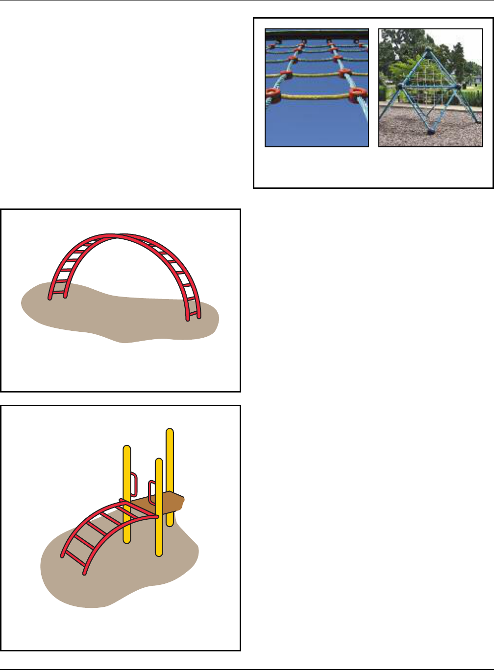
Figure 10. Freestanding arch climber
Figure 11. Arch climber access
Figure 12. Examples of two- and three-dimensional
flexible climbers
27
Handbook for Public Playground Safety
5.3.2.3 Flexible climbers
Flexible climbers use a grid of ropes, chains, cables, or tires
for climbing. Since the flexible parts do not provide a steady
means of support, flexible climbers require more advanced
balance abilities than rigid climbers.
Rope, chain, and cable generally form a net-like structure
that may be either two or three dimensional. See Figure 12.
Tire climbers may have the tires secured tread-to-tread to
form a sloping grid, or the tires may be suspended individual-
ly by chains or other means.
• Flexible climbers that provide access to platforms should
be securely anchored at both ends.
• When connected to the ground, the anchoring devices
should be installed below ground level and beneath the
base of the protective surfacing material.
• Connections between ropes, cables, chains, or between
tires should be securely fixed.
• Flexible climbers are not recommended as the sole means
of access to equipment intended for toddlers and
preschool-age children.
• Free-standing flexible climbers are not recommended on
playgrounds intended for toddlers and preschool children.
• Spacing between the horizontal and vertical components
of a climbing grid should not form entrapment hazards.
• The perimeter of any opening in a net structure should be
less than 17 inches or greater than 28 inches (see Figure
13).
5.3.2.2 Arch climbers
Arch climbers consist of rungs attached to convex side sup-
p
orts. They may be free standing (Figure 10) or be provided
as a more challenging means of access to other equipment
(Figure 11).
• Arch climbers should not be used as the sole means of
access to other equipment for preschoolers.
• Free standing arch climbers are not recommended for tod-
dlers or preschool-age children.
• The rung diameter and spacing of rungs on arch climbers
should follow the recommendations for rung ladders in
Table 6.

E
ntrapment hazard:
when the perimeter
of the net openings
is between 17 inches
and 28 inches
Should be less
than 17 inches
or greater than
28 inches
Figure 13. Entrapment hazards in flexible climbers
28
Handbook for Public Playground Safety
• The space between adjacent rungs of overhead ladders
should be greater than 9 inches to prevent entrapment.
• Horizontal ladders intended for preschool-age children
should have rungs that are parallel to one another and
evenly spaced.
• The maximum height of a horizontal ladder (i.e., mea-
sured from the center of the grasping device to the top of
the protective surfacing below) should be:
– Preschool-age (4 and 5 years): no more than 60 inches.
– School-age: no more than 84 inches.
• The center-to-center spacing of horizontal ladder rungs
should be as follows:
– Preschool-age (4 and 5 years): no more than 12 inches.
– School-age: no more than 15 inches.
• The maximum height of the take-off/landing platform
above the protective surfacing should be:
– Preschool-age (4 and 5 years): no more than 18 inches.
– School-age: no more than 36 inches.
5.3.2.4 Horizontal (overhead) ladders
Horizontal (overhead) ladders are a type of climber designed
to build upper body strength. They are designed to allow
children to move across the ladder from end to end using
only their hands.
Four-year-olds are generally the youngest children able to
use upper body devices like these; therefore, horizontal lad-
ders should not be used on playgrounds intended for toddlers
and 3-year-olds. The recommendations below are designed
to accommodate children ages 4 through 12 years.
• The first handhold on either end of upper body equip-
ment should not be placed directly above the platform
or climbing rung used for mount or dismount. This
minimizes the risk of children impacting rigid access
structures if they fall from the first handhold during
mount or dismount.
• The horizontal distance out to the first handhold should be:
– No greater than 10 inches but not directly above the
platform when access is from a platform.
– At least 8 inches but no greater than 10 inches when
access is from climbing rungs.

29
Handbook for Public Playground Safety
• Sliding poles should be continuous with no protruding
w
elds or seams along the sliding surface.
•
The pole should not change direction along the sliding
portion.
• The horizontal distance between a sliding pole and any
structure used for access to the sliding pole should be
between 18 inches and 20 inches.
• The pole should extend at least 60 inches above the level
of the platform or structure used for access to the sliding
pole.
• The diameter of sliding poles should be no greater than
1.9 inches.
• Sliding poles and their access structures should be located
so that traffic from other events will not interfere with the
users during descent.
• Upper access should be on one level only.
• The upper access area through the guardrail or barrier
should be 15 inches wide at most.
5.3.2.6.1 Fall height
• For sliding poles accessed from platforms, the fall height is
the distance between the platform and the protective sur-
facing beneath it.
• For sliding poles not accessed from platforms, the fall
height is the distance between a point 60 inches below
the highest point of the pole and the protective surfacing
beneath it.
• The top of the sliding pole’s support structure should not
be a designated play surface.
5.3.2.7 Track rides
Track rides are a form of upper body equipment where the
child holds on to a handle or other device that slides along a
track above his or her head. The child then lifts his or her
feet and is carried along the length of the track. Track rides
require significant upper body strength and the judgment to
know when it is safe to let go. These are skills not developed
until children are at least school-age; therefore, CPSC staff
recommends:
• Track rides should not be used on playgrounds for toddlers
and preschool-age children.
• Track rides should not have any obstacles along the path
of the ride, including anything that would interfere in the
take-off or landing areas.
5.3.2.5 Overhead rings
Overhead rings are similar to horizontal ladders in terms of
t
he complexity of use. Therefore, overhead rings should not
be used on playgrounds intended for toddlers and 3-year-
olds. The recommendations below are designed to accommo-
date children 4 through 12 years of age.
Overhead rings differ from horizontal ladders because, dur-
ing use, the gripped ring swings through an arc and reduces
the distance to the gripping surface of the next ring; there-
fore, the spacing distance recommendations for horizontal
ladders do not apply.
• The first handhold on either end of upper body equipment
should not be placed directly above the platform or climb-
ing rung used for mount or dismount. This minimizes the
risk of children hitting rigid access structures if they fall
from the first handhold during mount or dismount.
• The horizontal distance out to the first handhold should be:
– No greater than 10 inches but not directly above the
platform when access is from a platform.
– At least 8 inches but no greater than 10 inches when
access is from climbing rungs.
• The maximum height of overhead rings measured from
the center of the grasping device to the protective surfac-
ing should be:
– Preschool-age (4 and 5 years): 60 inches.
– School-age: 84 inches.
• If overhead swinging rings are suspended by chains, the
maximum length of the chains should be 7 inches.
• The maximum height of the take-off/landing platform
above the protective surfacing should be:
– Preschool-age (4 and 5 years): no more than 18 inches.
– School-age: no more than 36 inches.
5.3.2.6 Sliding poles
Vertical sliding poles are more challenging than some other
types of climbing equipment. They require upper body
strength and coordination to successfully slide down the
pole. Unlike other egress methods, there is no reverse or
stop, so a child cannot change his or her mind. Children
who start a sliding pole must have the strength to slide the
whole way or they will fall.
• Sliding poles are not recommended for toddlers or
preschool-age children since they generally don't have the
upper body and/or hand strength to slide.

Figure 14. Log roll
30
Handbook for Public Playground Safety
5.3.4 Merry-go-rounds
Merry-go-rounds are the most common rotating equipment
found on public playgrounds. Children usually sit or stand on
the platform while other children or adults push the merry-
go-round to make it rotate. In addition, children often get on
and off the merry-go-round while it is in motion. Merry-go-
rounds may present a physical hazard to preschool-age chil-
dren who have little or no control over such products once
they are in motion. Therefore, children in this age group
should always be supervised when using merry-go-rounds.
The following recommendations apply when the merry-go-
round is at least 20 inches in diameter.
• Merry-go-rounds should not be used on playgrounds
intended for toddlers.
• The standing/sitting surface of the platform should have a
maximum height of:
– Preschool: 14 inches above the protective surface.
– School-age: 18 inches above the protective surface.
• The rotating platform should be continuous and
approximately circular.
• The surface of the platform should not have any openings
between the axis and the periphery that permit a rod hav-
ing a diameter of 5/16 inch to penetrate completely
through the surface.
• Two track rides next to each other should be at least 4
f
eet apart.
•
The handle should be between 64 inches and 78 inches
from the surfacing and follow the gripping recommenda-
tions in §5.2.2.
• Nothing should ever be tied or attached to any moving
part of a track ride.
• Rolling parts should be enclosed to prevent crush hazards.
5.3.2.7.1 Fall height
• The fall height of track ride equipment is the distance
between the maximum height of the equipment and the
protective surface beneath it.
• Equipment support posts with no designated play surfaces
are exempt from this requirement.
5.3.3 Log rolls
Log rolls help older children master balance skills and
increase strength. Children must balance on top of the log as
they spin it with their feet. See Figure 14.
• Log rolls are not recommended for toddlers and
preschool-age children. These children generally do not
possess the balance, coordination, and strength to use a
log roll safely.
• Log rolls should have handholds to assist with balance.
• The handholds should follow the guidelines in §5.2.2.
• The highest point of the rolling log should be a maximum
of 18 inches above the protective surface below.
• When not part of a composite structure, the use zone may
overlap with neighboring equipment if the other piece of
equipment allows overlapping use zones (see §5.3.9) and
– There is at least 6 feet between equipment when
adjacent designated play surfaces are no more than
30 inches high; or
– There is at least 9 feet between equipment when
adjacent designated play surfaces are more than
30 inches high.
5.3.3.1.1 Fall height
The fall height of a log roll is the distance between the
highest portion of the rolling log and the protective
surfacing beneath it.
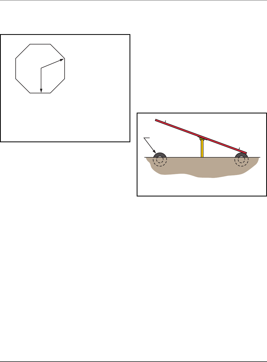
The difference between dimensions AC
and AB should not exceed 2.0 inches.
A = Axis of Rotation
AB = Minimum Radius
AC = Maximum Radius
A
B
Base
C
Figure 15. Minimum and maximum radii of a
merry-go-round platform
Automobile Tire
Figure 16. Typical Fulcrum Seesaw
31
Handbook for Public Playground Safety
5.3.4.2 Fall height
The fall height for a merry-go-round is the distance between
t
he perimeter of the platform where a child could sit or
stand and the protective surfacing beneath it.
5.3.5 Seesaws
5.3.5.1 Fulcrum seesaws
The typical seesaw (also known as a “teeter totter”) consists
of a board or pole with a seat at each end supported at the
center by a fulcrum. See Figure 16. Because of the complex
way children are required to cooperate and combine their
actions, fulcrum seesaws are not recommended for toddlers
or preschool-age children.
• The fulcrum should not present a crush hazard.
• Partial car tires, or some other shock-absorbing material,
should be embedded in the ground underneath the seats,
or secured on the underside of the seats. This will help
prevent limbs from being crushed between the seat and
the ground, as well as cushion the impact.
• The maximum attainable angle between a line connecting
the seats and the horizontal is 25°.
• There should not be any footrests.
5.3.5.2 Spring-centered seesaws
Preschool-age children are capable of using spring-centered
seesaws because the centering device prevents abrupt con-
tact with the ground if one child dismounts suddenly.
Spring-centered seesaws also have the advantage of not
requiring two children to coordinate their actions in order to
play safely. Spring-centered seesaws should follow the recom-
mendations for spring rockers including the use of footrests
(§5.3.7).
• The difference between the minimum and maximum radii
o
f a non-circular platform should not exceed 2.0 inches
(Figure 15).
• The underside of the perimeter of the platform should be
no less than 9 inches above the level of the protective
surfacing beneath it.
• There should not be any accessible shearing or crushing
mechanisms in the undercarriage of the equipment.
• Children should be provided with a secure means of hold-
ing on. Where handgrips are provided, they should con-
form to the general recommendations for hand gripping
components in §5.2.2.
• No components of the apparatus, including handgrips,
should extend beyond the perimeter of the platform.
• The rotating platform of a merry-go-round should not
have any sharp edges.
• A means should be provided to limit the peripheral speed
of rotation to a maximum of 13 ft/sec.
• Merry-go-round platforms should not have any up and
down (oscillatory) motion.
5.3.4.1 Use zone
• The use zone should extend a minimum of 6 feet beyond
the perimeter of the platform.
• The use zone may not overlap other use zones, unless the
rotating equipment is less than 20 inches in diameter and
the adjacent equipment allows overlap.

Exit close to horizontal
Slide chute
Platform
Hood or other means to channel
user into sitting position
Access ladder
or stairway
Figure 17. Typical Free-Standing Straight Slide
32
Handbook for Public Playground Safety
5.3.6 Slides
Children can be expected to
d
escend slide chutes in many dif-
ferent positions, rather than
always sitting and facing forward
as they slide. These other posi-
tions should be discouraged at all
times to minimize injuries.
Slides may provide a straight, wavy, or spiral descent either
by means of a tube or an open slide chute. They may be
either free-standing (Figure 17), part of a composite struc-
ture, or built on the grade of a natural or man-made slope
(embankment slide). Regardless of the type of slide, avoid
using bare metals on the platforms, chutes, and steps. When
exposed to direct sunlight the bare metal may reach temper-
atures high enough to cause serious contact burn injuries in
a matter of seconds. Provide shade for bare metal slides or
use other materials that may reduce the surface temperature
such as, but not limited to, plastic or coated metal.
5.3.6.1 Slide access
Access to a stand-alone slide generally is by means of a
ladder with rungs, steps, or a stairway with steps. Slides may
also be part of a composite play structure, so children will
gain access from other parts of the structure. Embankment
slides use the ground for access.
5.3.5.3 Use zone for fulcrum and spring-centered
s
eesaws
• The use zone should extend a minimum of 6 feet from
each outside edge of the seesaw.
• The use zone may overlap with neighboring equipment if
the other piece of equipment allows overlapping use zones
and
– There is at least 6 feet between equipment when
adjacent designated play surfaces are no more than
30 inches high; or
– There is at least 9 feet between equipment when
adjacent designated play surfaces are more than
30 inches high.
5.3.5.4 Handholds
• Handholds should be provided at each seating position
for gripping with both hands and should not turn when
grasped.
• Handholds should not protrude beyond the sides of the
seat.
5.3.5.5 Fall height
The fall height for a seesaw is the distance between the
highest point any part of the seesaw can reach and the
protective surfacing beneath it.

5.3.6.2 Slide platform
All slides should be provided with a platform with sufficient
l
ength to facilitate the transition from standing to sitting at
the top of the inclined sliding surface. Embankment slides
are exempt from platform requirements because they are on
ground level; however, they should not have any spaces or
gaps as noted below.
The platform should:
• Be at least 19 inches deep for toddlers.
• Be at least 14 inches deep for preschool-age and
school-age children.
• Be horizontal.
• Be at least as wide as the slide chute.
• Be surrounded by guardrails or barriers.
• Conform to the same recommendations as general
platforms given in §5.1.1.
• Not have any spaces or gaps that could trap strings,
clothing, body parts, etc. between the platform and the
start of the slide chute.
• Provide handholds to facilitate the transition from
standing to sitting and decrease the risk of falls (except
tube slides where the tube perimeter provides hand
support). These should extend high enough to provide
hand support for the largest child in a standing position,
and low enough to provide hand support for the smallest
child in a sitting position.
• Provide a means to channel a user into a sitting position
at the entrance to the chute, such as a guardrail, hood, or
other device that discourages climbing.
5.3.6.3 Slide chutes
5.3.6.3.1 Embankment slides
• The slide chute of an embankment slide should have a
maximum height of 12 inches above the underlying
ground surface. This design basically eliminates the hazard
of falls from elevated heights.
• Embankment slides should follow all of the recommenda-
tions given for straight slides where applicable (e.g., side
height, slope, use zone at exit, etc.).
• There should be some means provided at the slide chute
entrance to minimize the use of embankment slides by
children on skates, skateboards, or bicycles.
5.3.6.3.2 Roller slides
• Roller slides should meet applicable recommendations for
o
ther slides (e.g., side height, slope, use zone at exit, etc.).
• The space between adjacent rollers and between the ends
of the rollers and the stationary structure should be less
than 3/16 inch.
• Frequent inspections are recommended to insure that
there are no missing rollers or broken bearings and that
the rollers roll.
5.3.6.3.3 Spiral slides
• Spiral slides should follow the recommendations for
straight slides where applicable (e.g., side height, slope,
use zone at exit, etc.).
• Special attention should be given to design features which
may present problems unique to spiral slides, such as
lateral discharge of the user.
• Toddlers and preschool-age children have less ability to
maintain balance and postural control, so only short spiral
slides (one 360° turn or less) are recommended for these
age groups.
5.3.6.3.4 Straight slides
• Flat open chutes should have sides at least 4 inches high
extending along both sides of the chute for the entire
length of the inclined sliding surface.
• The sides should be an integral part of the chute, without
any gaps between the sides and the sliding surface. (This
does not apply to roller slides).
• Slides may have an open chute with a circular, semicircu-
lar or curved cross section provided that:
A. The vertical height of the sides is no less than 4 inches
when measured at right angles to a horizontal line
that is 8 inches long when the slide is intended for
toddlers, 12 inches long when the slide is intended for
preschool-age children, and 16 inches long when the
slide is intended for school-age children (Figure 18);
or
B. For any age group, the vertical height of the sides is no
less than 4 inches minus two times the width of the
slide chute divided by the radius of the slide chute
curvature (Figure 19).
33
Handbook for Public Playground Safety

Slide Chute Width
Chute Radius
H
2 x Slide Chute Width
Slide Chute Radius
H = 4 -
Figure 19. Formula for Minimum Vertical Side Height for Slide with Curved Chute
4 in. min.
Slide Chute
8 in. min. (toddler)
12 in. min. (preschool-age)
16 in. min. (school-age)
Bottom of slide. Subject only to general
requirements for protrusions in §3.2
90° 90°
Figure 18. Minimum Side Height for Slide with Circular Cross Section
34
Handbook for Public Playground Safety

Height (H)
of platform
above exit
Horizontal distance (D) of exit
from beginning of slide chute
Platform
Figure 20. Slide Slope
35
Handbook for Public Playground Safety
5.3.6.4 Chute exit region
All slides should have an exit region to help children main-
t
ain their balance and facilitate a smooth transition from sit-
ting to standing when exiting. The chute exit region should:
• Be between 0 and -4° as measured from a plane parallel to
the ground.
• Have edges that are rounded or curved to prevent lacera-
tions or other injuries that could result from impact with a
sharp or straight edge.
• For toddlers the chute exit region should:
– Be between 7 and 10 inches long if any portion of the
chute exceeds a 24° slope.
– Be no more than 6 inches above the protective
surfacing.
– Have a transition from the sliding portion to the exit
region with a radius of curvature of at least 18 inches.
• For preschool- and school-age the chute exit region
should:
– Be at least 11 inches long.
– Be no more than 11 inches above the protective
surfacing if the slide is no greater than 4 feet high.
– Be at least 7 inches but not more than 15 inches above
the protective surfacing if the slide is over 4 feet high.
• For toddlers:
– The average incline of a slide chute should be no more
t
han 24° (that is, the height to horizontal length ratio
shown in Figure 20 does not exceed 0.445).
– No section of the slide chute should have a slope
greater than 30°.
– The slide chute should be between 8 and 12 inches wide.
• For preschool- and school-age children:
– The average incline of a slide chute should be no more
than 30° (that is, the height to horizontal length ratio
shown in Figure 20 does not exceed 0.577).
– No section of the slide chute should have a slope
greater than 50°.
5.3.6.3.5 Tube slides
• Tube slides should meet all the applicable recommenda-
tions for other slides (e.g., side height, slope, use zone at
exit, etc.).
• Means, such as barriers or textured surfaces, should be
provided to prevent sliding or climbing on the top
(outside) of the tube.
• The minimum internal diameter of the tube should be no
less than 23 inches.
• Supervisors should be aware of children using tube slides
since the children are not always visible.

6 ft.
Slide
Exit
Zone
H
Denotes Use Zone with Protective Surfacing
6 ft.
6 ft.
min,
8 ft.
max
Figure 21. Use zone for stand-alone slides
36
Handbook for Public Playground Safety
• Projections up to 3 inches in diameter should not stick up
more than 1/8 inch from the slide.
• There should be no gaps at the tops of slides where the
slide chute connects with the platform that can entangle
clothing or strings.
• See Appendix B for full recommendations and details of
the protrusion test procedure.
5.3.6.8 Other sliding equipment
Equipment where it is foreseeable that a primary use of the
component is sliding should follow the same guidelines for
entanglement that are in 5.3.6.7.
5.3.7 Spring rockers
Toddlers and preschool-age children enjoy the bouncing and
rocking activities presented by spring rockers, and they are
the primary users of rocking equipment. See Figure 22. Older
children may not find it challenging enough.
• Seat design should not allow the rocker to be used by
more than the intended number of users.
5.3.6.5 Slide use zone
Toddlers:
• In a limited access environment
– The use zone should be at least 3 feet around the
perimeter of the slide.
– The area at the end of the slide should not overlap with
the use zone for any other equipment.
• In public areas with unlimited access
– For a stand-alone slide, the use zone should be at least
6 feet around the perimeter.
– For slides that are part of a composite structure, the
minimum use zone between the access components and
the side of the slide chute should be 3 feet.
– The use zone at the end of the slide should be at least 6
feet from the end of the slide and not overlap with the
use zone for any other equipment.
Preschool- and school-age (see Figure 21):
• The use zone in front of the access and to the sides of a
slide should extend a minimum of 6 feet from the perime-
ter of the equipment. This recommendation does not
apply to embankment slides or slides that are part of a
composite structure (see §5.3.9).
• The use zone in front of the exit of a slide should never
overlap the use zone of any other equipment; however,
two or more slide use zones may overlap if their sliding
paths are parallel.
• For slides less than or equal to 6 feet high, the use zone in
front of the exit should be at least 6 feet.
• For slides greater than 6 feet high, the use zone in front of
the exit should be at least as long as the slide is high up to
a maximum of 8 feet.
5.3.6.6 Fall height
The fall height for slides is the distance between the transi-
tion platform and the protective surfacing beneath it.
5.3.6.7 Entanglement hazard
Children have suffered serious injuries and died by getting
parts of their clothing tangled on protrusions or gaps on
slides.
To reduce the chance of clothing entanglement:

Figure 22. Example of spring rocker
37
Handbook for Public Playground Safety
– There is at least 9 feet between equipment when
a
djacent designated play surfaces are more than 30
inches high; and
– The spring rocker is designed to be used from a seated
position.
5.3.7.1 Fall height
The fall height of spring rockers is the distance between
either (1) the highest designated playing surface or (2) the
seat, whichever is higher, and the protective surfacing
beneath it.
5.3.8 Swings
Children of all ages generally enjoy the sensations created
while swinging. Mostly they sit on the swings; however, it
is common to see children jumping off swings. Younger
children also tend to swing on their stomachs, and older
children may stand on the seats. To prevent injuries, these
behaviors should be discouraged.
Swings may be divided into two distinct types:
• Single axis: Sometimes called a to-fro swing. A single-axis
swing is intended to swing back and forth in a single plane
and generally consists of a seat supported by at least two
suspending members, each of which is connected to a
separate pivot on an overhead structure.
• Multi-axis: A multi-axis swing consists of a seat (generally
a tire) suspended from a single pivot that permits it to
swing in any direction.
5.3.8.1 General swing recommendations
• Hardware used to secure the suspending elements to the
swing seat and to the supporting structure should not be
removable without the use of tools.
• S-hooks are often part of a swing’s suspension system,
either attaching the suspending elements to the overhead
support bar or to the swing seat. Open S-hooks can catch
a child’s clothing and present a strangulation hazard. S-
hooks should be pinched closed. An S-hook is considered
closed if there is no gap or space greater than 0.04 inches
(about the thickness of a dime).
• Swings should be suspended from support structures that
discourage climbing.
• A-frame support structures should not have horizontal
cross-bars.
• For toddlers:
– The seat should be between 12 and 16 inches high.
– Spring rockers with opposing seats intended for more
than one child should have at least 37 inches between
the seat centers.
• For preschoolers:
– The seat should be between 14 and 28 inches high.
• Each seating position should be equipped with handgrips
and footrests. The diameter of handgrips should follow
the recommendations for hand gripping components in
§5.2.2.
• The springs of rocking equipment should minimize the
possibility of children crushing their hands or their feet
between coils or between the spring and a part of the
rocker.
• The use zone should extend a minimum of 6 feet from the
“at rest” perimeter of the equipment.
• The use zone may overlap with neighboring equipment if
the other piece of equipment allows overlapping use zones
and
– There is at least 6 feet between equipment when
adjacent designated play surfaces are no more than
30 inches high; or

D1
D2
D1
D3
60"
D4 D4
Figure 23. Minimum Clearances for Single-Axis Swings
Table 7. Minimum clearance dimensions for swings
Reason Dimension Toddler Preschool-age School-age
Full bucket Belt Belt
Minimizes collisions between D1 20 inches 30 inches 30 inches
a swing and the supporting
structure
Minimizes collisions between D2 20 inches 24 inches 24 inches
swings
Allows access D3 24 inches 12 inches 12 inches
Reduces side-to-side motion D4 20 inches 20 inches 20 inches
38
Handbook for Public Playground Safety
5.3.8.2 Fall height
The fall height for swings is the vertical distance between
the pivot point and the protective surfacing beneath it.
5.3.8.3 Single-axis swings
5.3.8.3.1 Belt seats used without adult assistance
• The use zone to the front and rear of single-axis swings
should never overlap the use zone of another piece of
equipment.
• To minimize the likelihood of children being struck by a
moving swing, it is recommended that no more than two
single-axis swings be hung in each bay of the supporting
structure.
• Fiber ropes are not recommended as a means of suspend-
ing swings since they may degrade over time.
• Swing structures should be located away from other
equipment or activities to help prevent young children
from inadvertently running into the path of moving
swings. Additional protection can be provided by means
of a low blockade such as a fence or hedge around the
perimeter of the swing area. The blockade should not be
an obstacle within the use zone of a swing structure or
hamper supervision by blocking visibility.

Figure 24. Example of full bucket seat swings
39
Handbook for Public Playground Safety
• The full bucket seat materials should not present a stran-
g
ulation hazard, such as might be presented with a rope or
chain used as part of the seat.
• Openings in swing seats should conform to the entrap-
ment criteria in §3.3.
• Full bucket seat swings should be suspended from
structures that are separate from those for other swings,
or at least suspended from a separate bay of the same
structure.
• Full bucket seat swings should not allow the child to enter
and exit alone.
• Pivot points should be more than 47 inches but no more
than 96 inches above the protective surfacing.
5.3.8.3.3 Use zone for single-axis swings – belt and full
bucket
The use zone in front of and behind the swing should be
greater than to the sides of such a swing since children may
deliberately attempt to exit from a single-axis swing while it
is in motion. See Figure 25.
• The use zone for a belt swing should extend to the front
and rear of a single-axis swing a minimum distance of
twice the vertical distance from the pivot point and the
top of the protective surface beneath it.
• The use zone for a full bucket swing should extend to the
front and rear a minimum of twice the vertical distance
from the top of the occupant’s sitting surface to the pivot
point.
• The use zone in front of and behind swings should never
overlap with any other use zone.
• The use zone to the sides of a single-axis swing should
extend a minimum of 6 feet from the perimeter of the
swing. This 6-foot zone may overlap that of an adjacent
swing structure or other playground equipment structure.
5.3.8.4 Multi-axis (tire) swings
Tire swings are usually suspended in a horizontal orientation
using three suspension chains or cables connected to a single
swivel mechanism that permits both rotation and swinging
motion in any axis.
• A multi-axis tire swing should not be suspended from a
structure having other swings in the same bay.
• Attaching multi-axis swings to composite structures is not
recommended.
• Swings should not be attached to composite structures.
• Swing seats should be designed to accommodate no more
t
han one user at any time.
• Lightweight rubber or plastic swing seats are recommend-
ed to help reduce the severity of impact injuries. Wood or
metal swing seats should be avoided.
• Edges of seats should have smoothly finished or rounded
edges and should conform to the protrusion recommenda-
tions in 5.3.8.5.
• If loose-fill material is used as a protective surfacing, the
height recommendations should be determined after the
material has been compressed.
5.3.8.3.2 Full bucket seat swings
Full bucket seat swings are similar to single-axis swings since
they move in a to-fro direction. However, full bucket seat
swings are intended for children under 4 years of age to use
with adult assistance.
• The seats and suspension systems of these swings, includ-
ing the related hardware, should follow all of the criteria
for conventional single axis swings.
• Full bucket seats are recommended to provide support on
all sides of a child and between the legs of the occupant
(see Figure 24).

Denotes Use Zone with Protective Surfacing
2H
H
2H
6 ft.
6 ft.
6 ft.
6 ft.
Figure 25. Use Zone for Single-Axis Belt Swings
Denotes Use Zone with Protective Surfacing
L
6 ft.
L+6 ft.
6 ft.
Figure 27. Use Zone for Multi-Axis Swings
30" Min.
Figure 26. Multi-Axis Swing Clearance
40
Handbook for Public Playground Safety
5.3.8.4.1 Multi-axis swing use zones
• The use zone should extend in any direction from a point
d
irectly beneath the pivot point for a minimum distance
of 6 feet plus the length of the suspending members (see
Figure 27). This use zone should never overlap the use
zone of any other equipment.
• To minimize the hazard of impact, heavy truck tires
s
hould be avoided. Further, if steel-belted radials are used,
they should be closely examined to ensure that there are
no exposed steel belts or wires that could be a potential
protrusion or laceration hazard. Plastic materials can be
used as an alternative to simulate actual automobile tires.
Drainage holes should be provided in the underside of the
tire.
• Pay special attention to maintenance of the hanger mech-
anism because the likelihood of failure is higher for tire
swings due to the added stress of rotational movement
and multiple occupants.
• The hanger mechanisms for multi-axis tire swings should
not have any accessible crush points.
• The minimum clearance between the seating surface of a
tire swing and the uprights of the supporting structure
should be 30 inches when the tire is in a position closest
to the support structure (Figure 26).
• The minimum clearance between the bottom of the seat
and the protective surface should not be less than 12
inches.

Denotes Use Zone with
Protective Surfacing
6 ft.
6 ft.
6 ft.
6 ft.
6 f
t
.
6 f
t
.
6 ft. MIN
8 ft. MAX
STEPPING
FORMS
SLIDE
Figure 28. Use Zones for Composite Structure
41
Handbook for Public Playground Safety
5.3.10 Fall height and use zones not specified
e
lsewhere
Most playground equipment belongs in one of the categories
listed above. If it does not, the following general recommen-
d
ations should be applied:
• The fall height of a piece of playground equipment is the
distance between the highest designated playing surface
and the protective surface beneath it.
• The use zone should extend a minimum of 6 feet in all
directions from the perimeter of the equipment.
• The use zones of two stationary pieces of playground
equipment that are positioned adjacent to one another
may overlap if the adjacent designated play surfaces of
each structure are no more than 30 inches above the pro-
tective surface and the equipment is at least 6 feet apart.
• If adjacent designated play surfaces on either structure
exceed a height of 30 inches, the minimum distance
between the structures should be 9 feet.
• Use zones should be free of obstacles.
• The use zone should extend a minimum of 6 feet from the
p
erimeter of the supporting structure. This 6-foot zone
may overlap that of an adjacent swing structure or other
playground equipment structure.
5.3.8.5 Protrusions on suspended members of
swing assemblies
Protrusions on swings are extremely hazardous because of
the potential for impact incidents. Nothing, including bolts
or other parts, on the front, back, or underside of a swing
should stick out more than 1/8 of an inch. See test proce-
dures in Appendix B.
5.3.9 Fall height and use zones for composite
structure
When two or more complementary play components are
linked together in a composite structure (e.g., combination
climber, slide, and horizontal ladder), the use zone should
extend a minimum of 6 feet from the external perimeter of
the structure (see Figure 28). Where slides are attached to a
platform higher than 6 feet from the protective surfacing, the
use zone may need to extend further in front of the slide (see
§5.3.6.5).
Figure adapted from
ASTM F1487

S
urfacing (§2.4)
Adequate protective surfacing under and around the
equipment.
Install/replace surfacing
Surfacing materials have not deteriorated.
Replace surfacing
Other maintenance: __________________________
Loose-fill surfacing materials have no foreign
objects or debris.
Remove trash and debris
Loose-fill surfacing materials are not compacted.
Rake and fluff surfacing
Loose-fill surfacing materials have not been dis-
placed under heavy use areas such as under swings
or at slide exits.
Rake and fluff surfacing
Drainage (§2.4)
The entire play area has satisfactory drainage, espe-
cially in heavy use areas such as under swings and
at slide exits.
Improve drainage
Other maintenance: __________________________
General Hazards
There are no sharp points, corners or edges on the
equipment (§3.4).
There are no missing or damaged protective caps or
plugs (§3.4).
There are no hazardous protrusions (§3.2 and
Appendix B).
There are no potential clothing entanglement haz-
ards, such as open S-hooks or protruding bolts
(§2.5.2, §3.2, §5.3.8.1 and Appendix B).
There are no crush and shearing points on exposed
moving parts (§3.1).
There are no trip hazards, such as exposed footings
or anchoring devices and rocks, roots, or any other
obstacles in a use zone (§3.6).
Security of Hardware (§2.5)
There are no loose fastening devices or worn con-
nections.
Replace fasteners
Other maintenance: _________________________
M
oving parts, such as swing hangers, merry-go-
round bearings, and track rides, are not worn.
Replace part
Other maintenance: _________________________
Durability of Equipment (§2.5)
There are no rust, rot, cracks, or splinters on any
equipment (check carefully where it comes in con-
tact with the ground).
There are no broken or missing components on the
equipment (e.g., handrails, guardrails, protective
barriers, steps, or rungs).
There are no damaged fences, benches, or signs on
the playground.
All equipment is securely anchored.
Leaded Paint (§2.5.4)
Paint (especially lead paint) is not peeling, cracking,
chipping, or chalking.
There are no areas of visible leaded paint chips or
accumulation of lead dust.
Mitigate lead paint hazards
General Upkeep of Playgrounds (§4)
There are no user modifications to the equipment,
such as strings and ropes tied to equipment, swings
looped over top rails, etc.
Remove string or rope
Correct other modification
The entire playground is free from debris or litter
such as tree branches, soda cans, bottles, glass, etc.
Clean playground
There are no missing trash receptacles.
Replace trash receptacle
Trash receptacles are not full.
Empty trash
APPENDIX A: SUGGESTED GENERAL MAINTENANCE CHECKLISTS
NOTES:
DATE OF INSPECTION: INSPECTION BY:
43
Handbook for Public Playground Safety

Handbook for Public Playground Safety
44
Routine Inspection and Maintenance Issues
Broken equipment such as loose bolts, missing end caps,
cracks, etc.
Broken glass & other trash
Cracks in plastics
Loose anchoring
Hazardous or dangerous debris
Insect damage
Problems with surfacing
Displaced loose-fill surfacing (see Section 4.3)
Holes, flakes, and/or buckling of unitary surfacing
User modifications (such as ropes tied to parts or
equipment rearranged)
Vandalism
Worn, loose, damaged, or missing parts
Wood splitting
Rusted or corroded metals
Rot

Handbook for Public Playground Safety
45
APPENDIX B: PLAYGROUND TESTING
3.0 inch interior
diameter
1.5 inch interior
diameter
0.50 inch interior
diameter
0.25 inch
thick
1.0
inch exterior
diameter
0.75 inch
thick
2.0
inch exterior
diameter
1.5 inch thick
3.5
inch exterior
diameter
Figure B1. Projection test gauges
1.25 inch max
1/8 inch max.
2 inch max.
Note: gauge made of any rigid material
Figure B2. Projection test gauge for suspended swing assemblies and slides
B.1 Templates, Gauges, and Testing Tools
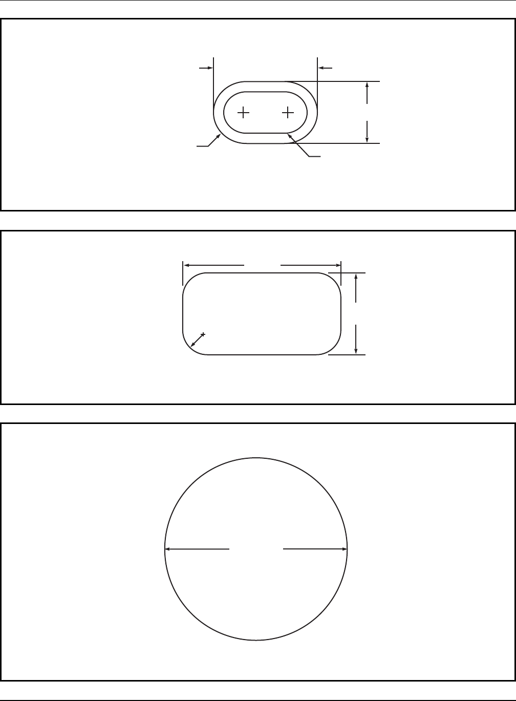
Handbook for Public Playground Safety
46
9
.0 in
. dia
.
Figure B5. Large head template
6.2 in.
3.5 in.
1.2 in. rad
Figure B4. Preschool- and school-age small torso template
3.0 in. (76 mm)
5.0 in. (130 mm)
R1.5 in. (R38 mm)
R1.0 in. (R25 mm)
Figure B3. Toddler small torso template

Handbook for Public Playground Safety
47
1.0 in.
6.2 in.
5.2 in.
4.0 in.
3.5 in.
1.2 in. Rad. 0.7 in. Rad.
0.5 in.
Figure B7. Preschool- and school-age small torso probe
1.0 in.
3.0 in.
5.0 in.
Radius = 1.5 in.
Radius = 1.0 in.
3.0 in.
Figure B6. Toddler small torso probe
1.0 in.
4.0 in.
8.0 in.
9.0 in.
dia.
Figure B8. Large head probe
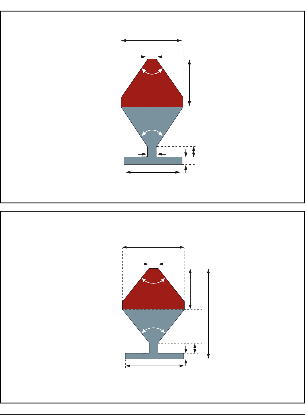
Handbook for Public Playground Safety
48
1.4
75°
Section A
8.2
6.7
5.0
1.0
0.8
11.2
75°
Section B
Figure B10. Toddler partially bound probe (dimensions in inches, template is 0.60 inches thick)
Section A
Section B
6.1
8.5
0.75
3.0
55°
55°
4.75
1.875
1.875
Figure B9. Preschool/School-age partially bound probe (dimensions in inches, template is 0.75 inches thick)
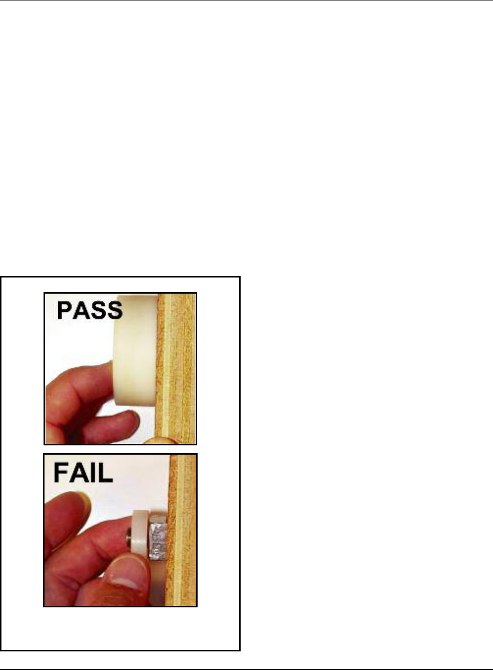
Handbook for Public Playground Safety
49
B.2 Test Methods
B.2.1 Determining whether a projection is a
protrusion
B.2.1.1 Test procedure
Step 1: Successively place each projection test gauge (see
Figure B1) over any projection
Step 2: Visually determine if the projection penetrates
through the hole and beyond the face of the gauge
(see Figure B11 below).
Pass: A projection that does not extend beyond the
face of the gauge passes.
Fail: A projection that extends beyond the face of
any one of the gauges is considered a haz-
ardous protrusion and should be eliminated.
B.2.2 Projections on suspended members of swing
assemblies
Given the potential for impact incidents, projections on
swings can be extremely hazardous. A special test gauge (see
Figure B2) and procedure are recommended. When tested,
no bolts or components in the potential impact region on
suspended members should extend through the hole beyond
the face of the gauge.
B.2.2.1 Test procedure
Step 1: Hold the gauge (Figure B2) vertically with the axis
through the hole parallel to the swing’s path of
travel.
Step 2: Place the gauge over any projections that are
exposed during the swing’s path of travel.
Step 3: Visually determine if the projection penetrates
through the hole and beyond the face of the gauge.
Pass: A projection that does not extend beyond the
face of the gauge passes.
Fail: A projection that extends beyond the face of
the gauge is considered a hazardous protrusion
and should be eliminated.
B.2.3 Projections on slides
To minimize the likelihood of clothing entanglement on
slides, projections that (1) fit within any one of the three
gauges shown in Figure B1 and (2) have a major axis that
projects away from the slide bed should not have projections
greater than 1/8 inch perpendicular to the plane of the sur-
rounding surface (Figure B12).
B.2.3.1 Test procedure
Step 1: Identify all projections within the shaded area
shown in Figure B13.
Step 2: Determine which, if any, fit inside the projection
test gauges (Figure B1).
Step 3: Place the swing and slide projection gauge (Figure
B2) next to the projection to check the height of
the projection.
APPENDIX B: PLAYGROUND TESTING
Figure B11. Determining whether a
projection is a protrusion

Step 4: Visually determine if the projection extends beyond
t
he face of the slide projection gauge.
P
ass: A projection that does not extend beyond the
face of the gauge passes.
Fail: A projection that extends beyond the face of
the gauge is considered a hazardous protrusion
and should be eliminated.
NOTE: This test procedure is not applicable to the underside of
a slide chute. For a slide chute with a circular cross section, the
portion of the underside not subject to this projection recommen-
dation is shown in Figure 18. The general recommendations for
projections in §B.2.1 are applicable to the underside of the slide.
Handbook for Public Playground Safety
50
SLIDING SURFACE
21" R
21" R
42"
19" Toddlers/
14" Preschool/School
SHADED AREA REPRESENTS
NON-ENTANGLEMENT/PROTRUSION
ZONES
EXIT
SECTION
SIDEWALL
60"
STANDING
HEIGHT
21" R
PERPENDICULAR
SURFACE
1
/8 Inch maximum
Figure B13. Recommended areas to test for slide entanglement protrusions
HORIZONTAL PLANE
1/8 inch maximum
Figure B12. Upward facing projection

B.2.4 Entrapment
B.2.4.1 General
Any completely-bounded opening (Figure B14) that is not
bounded by the ground may be a potential head entrapment
hazard. Even those openings which are low enough to permit
a child’s feet to touch the ground present a risk of strangula-
tion to an entrapped child, because younger children may
not have the necessary intellectual ability and motor skills to
withdraw their heads, especially if scared or panicked. An
opening may present an entrapment hazard if the distance
between any interior opposing surfaces is greater than 3.5
inches and less than 9 inches. If one dimension of an open-
ing is within this potentially hazardous range, all dimensions
of the opening should be considered together to fully evalu-
ate the possibility of entrapment. The most appropriate
method to determine whether an opening is hazardous is to
test it using the following fixtures, methods, and perfor-
mance criteria.
These recommendations apply to all playground equipment,
i.e., toddler, preschool-age, and school-age children. Fixed
equipment as well as moving equipment (in its stationary
position) should be tested for entrapment hazards. There are
two special cases for which separate procedures are given:
(1) completely-bounded openings where depth of penetra-
tion is a critical issue (see Figure B15) and (2) openings
formed by flexible climbing components.
Handbook for Public Playground Safety
51
Ground-bounded: Not subject to entrapment recommendations.
Low entrapment
High entrapment
Figure B14. Examples of completely
bounded openings
Limiting Depth
Figure B15. Completely bounded opening with
limited depth

B.2.5 Test fixtures
Two templates are required to determine if completely
bounded openings in rigid structures present an entrapment
hazard. These templates can easily be fabricated from card-
b
oard, plywood, or sheet metal.
B.2.5.1 Small torso template
The dimensions (see Figure B3 and Figure B4) of this tem-
plate are based on the size of the torso of the smallest user at
risk (5th percentile 6-month-old child for Figure B3 and 2-
year-old child for Figure B4). If an opening is too small to
admit the template, it is also too small to permit feet first
entry by a child. Because children’s heads are larger than
their torsos, an opening that does not admit the small torso
template will also prevent head first entry into an opening by
a child.
B.2.5.2 Large head template
The dimensions (see Figure B5) of this template are based
on the largest dimension on the head of the largest child at
risk (95th percentile 5-year-old child). If an opening is large
enough to permit free passage of the template, it is large
enough to permit free passage of the head of the largest child
at risk in any orientation. Openings large enough to permit
free passage of the large head template will not entrap the
chest of the largest child at risk.
B.2.5.3 Completely bounded openings with
unlimited depth
B.2.5.3.1 Test procedure
Step 1: Select the appropriate small torso template based
on the intended users of the playground (Figure B3
for toddler playgrounds, Figure B4 for preschool-
and school-age playgrounds).
Step 2: Identify all completely bounded openings.
Step 3: Attempt to place the small torso template in the
opening with the plane of the template parallel to
the plane of the opening. While keeping it parallel
to the plane of the opening, the template should be
rotated to its most adverse orientation (i.e., major
axis of template oriented parallel to the major axis
of the opening.)
Step 4: Determine if the small torso template can freely
p
ass through the opening.
N
o: Pass. Stop Yes: Continue
Step 5: Place the large head template in the opening, again
with the plane of the template parallel to the plane
of the opening, and try to insert it through the
opening.
Pass: The large head template can be freely insert-
ed through the opening
Fail: The opening admits the small torso template
but does not admit the large head template.
Handbook for Public Playground Safety
52

B.2.5.4 Completely bounded openings with
l
imited depth of penetration
The configuration of some openings may be such that the
depth of penetration is a critical issue for determining the
e
ntrapment potential. For example, consider a vertical wall
or some other barrier behind a step ladder. The entrapment
potential depends not only on the dimensions of the opening
between adjacent steps but also on the horizontal space
between the lower boundary of the opening and the barrier.
A child may enter the opening between adjacent steps feet
first and may proceed to pass through the space between the
rear of the lower step and the barrier and become entrapped
when the child’s head is unable to pass through either of
these two openings. In effect, there are openings in two dif-
ferent planes, and each has the potential for head entrap-
ment and should be tested.
Figure B16 illustrates these two planes for a step ladder as
well as for a generic opening. Plane A is the plane of the
completely bounded opening in question, and Plane B is the
plane of the opening encompassing the horizontal space
between the lower boundary of the opening in Plane A and
the barrier that should also be tested for entrapment hazards.
B.2.5.4.1 Test procedure
Step 1: Select the appropriate small torso template based
on the intended users of the playground (Figure B3
for toddler playgrounds, Figure B4 for preschool-age
and school-age playgrounds).
Step 2: Identify all completely bounded openings with lim-
i
ted depth of penetration.
S
tep 3: Place the small torso template in the opening in
Plane A with its plane parallel to Plane A; rotate
the template to its most adverse orientation with
respect to the opening while keeping it parallel to
Plane A.
Step 4: Determine if the opening in Plane A admits the
small torso template in any orientation when rotat-
ed about its own axis.
No: Pass. The opening is small enough to prevent
either head first or feet first entry by the
smallest user at risk and is not an entrapment
hazard.
Yes: Continue.
Step 5: Place the small torso template in the opening in
Plane B with its plane parallel to Plane B; rotate the
template to its most adverse orientation with
respect to the opening while keeping it parallel to
Plane B.
Step 6: Determine if the opening in Plane B admits the
small torso template.
No: Pass. The depth of penetration into the open-
ing in Plane A is insufficient to result in
entrapment of the smallest user at risk.
Yes: Continue.
Step 7: Place the large head template (Figure B5) in the
opening in Plane A with its plane parallel to Plane
A. Determine if the opening in Plane A admits the
large head template.
No: Fail. A child, whose torso can enter the open-
ing in Plane A as well as the opening in Plane
B, may become entrapped by the head in the
opening in Plane A.
Yes: Continue.
Step 8: With the plane of the large head template parallel
to the opening in Plane B, determine if the opening
in Plane B admits the large head template.
No: Fail. The largest user at risk cannot exit the
opening in Plane B.
Yes: Pass. The openings in Plane A and Plane B do
not pose an entrapment risk.
Handbook for Public Playground Safety
53
Plane
B
Plane A
Plane A
Plane B
Figure B16. Example of a completely bounded
opening with limited depth of penetration

Handbook for Public Playground Safety
54
Step 6: Place the large head probe (Figure B8) in the open-
i
ng with the plane of its base parallel to the plane of
the opening.
Step 7: Determine if the large head probe can be pushed or
pulled completely through the opening by a force
no greater than 30 pounds on toddler playgrounds
or 50 pounds on preschool-age and school-age play-
grounds.
Yes: Pass. Stop.
No: Fail.
B.2.5.5 Flexible openings
Climbing components such as flexible nets are also a special
c
ase for the entrapment tests because the size and shape of
openings on this equipment can be altered when force is
applied, either intentionally or simply when a child climbs on
or falls through the openings. Children are then potentially
at risk of entrapment in these distorted openings.
The procedure for determining conformance to the entrap-
ment recommendations for flexible openings requires two
three-dimensional test probes which are illustrated in Figure
B6, Figure B7, and Figure B8 are applied to an opening in a
flexible component with a force of up to 50 pounds.
B.2.5.5.1 Test procedure
Step 1: Select the appropriate small torso template based
on the intended users of the playground (Figure B3
for toddler playgrounds, Figure B4 for preschool-age
and school-age playgrounds).
Step 2: Identify all completely bounded openings with flexi-
ble sides.
Step 3: Place the small torso probes (Figures B6 and B7) in
the opening, tapered end first, with the plane of its
base parallel to the plane of the opening.
Step 4: Rotate the probe to its most adverse orientation
(major axis of probe parallel to major axis of open-
ing) while keeping the base parallel to the plane of
the opening.
Step 5: Determine if the probe can be pushed or pulled
completely through the opening by a force no
greater than 30 pounds on toddler playgrounds or
50 pounds on preschool-age and school-age play-
grounds.
No: Pass. Stop Yes: Continue.
PASS
FAIL
PASS

Handbook for Public Playground Safety
55
Examples of partially bound openings. Note, these examples are intended to illustrate the principle
of partially bound openings and may or may not require testing.
Identifying partially bound openings varies depending on the
a
ge range of the playground. Openings that should be tested
include any opening where:
For toddlers:
• The perimeter of the opening is not closed
• The lowest leg of the opening is tilted upward (i.e. above
horizontal) or 45 degrees below horizontal.
For preschool- and school-age:
• The perimeter of the opening is not closed
• The lowest leg of the opening is tilted upward (i.e. above
horizontal)
B.2.5.6 Partially bound openings
A partially bound opening is any opening which has at least
one side or portion open, such as a U- or V-shaped opening.
These openings can still pose an entrapment hazard by
a
llowing the neck to enter but not allowing the head to slip
out. A partially bound opening can be any part of the play-
ground equipment where a child could get his or her neck
caught, so it includes not only two- or three-sided openings,
but also areas of large openings (large enough for the head
template to enter) that have the characteristics that can
entrap a child’s neck. Several examples outlines of this situa-
tion are shown in the figures below. Openings that have an
outline similar to these figures are often found when two
parts of a playground meet, for example, the top of a slide
and the side of a guardrail.

Handbook for Public Playground Safety
56
Step 6: While still inserted as far as possible, determine if
t
here is simultaneous contact between both of the
angled sides of section A and the sides of the
opening.
Yes: Note the points No: Pass. The narrow
on the sides of tip should be
opening where resting on the
contact was made lower boundary of
and continue the opening with
no contact with
the sides of the
opening. Stop
Step 7: Remove the template and turn the template so that
the face of the template is perpendicular to the
opening.
Step 8: Following the plane of the opening, insert the B
portion of the template into the opening so that the
narrow part of the B portion is between the sides of
the opening.
B.2.5.6.1 Test procedure
Step 1: Select the appropriate Partially Bound Template
b
ased on the intended users of the playground
(Figure B10 for toddler playgrounds, Figure B9 for
preschool and school-age playground).
Step 2: Identify partially bound openings.
Step 3: Align the template so that the face of the template
is parallel to the plane of the opening and the nar-
row tip of the A section is pointing toward the
opening.
Step 4: Insert the A portion of the template into the open-
ing following the centerline of the opening.
Step 5: Once inserted as far as possible, determine if there
is simultaneous contact between the sides of the
opening and both of the top corners at the narrow
tip of section A.
Yes: Pass. Stop No: continue
56
Openings shown are
for example purposes
only. Yours may be
shaped or oriented
differently.
Side View
A
B
Side View
A
B
Side View Top View
A
B
PASS
PASS

Step 9: Once inserted as far as possible, determine if the B
p
ortion is completely past the points where contact
was made on the sides of the opening with the A
portion.
No: Pass. Stop Yes: Toddlers:
Fail. Stop
Preschool and
School-age:
Continue
Step 10: Determine if the B portion can reach a point where
the opening increases in size.
No: Fail. Stop Yes: continue
Step 11: Determine if the Large Head Template passes freely
t
hrough the larger opening.
Y
es: Pass No: Fail
Handbook for Public Playground Safety
57
PASS
PASS
FAIL
FAIL
U.S. CONSUMER PRODUCT
SAFETY COMMISSION
4330 EAST WEST HIGHWAY
BETHESDA, MD 20814
OFFICIAL BUSINESS
PENALTY FOR PRIVATE USE, $300
AN EQUAL OPPORTUNITY EMPLOYER
