
Cisco Identity Services Engine Installation Guide, Release 3.1
First Published: 2021-08-03
Americas Headquarters
Cisco Systems, Inc.
170 West Tasman Drive
San Jose, CA 95134-1706
USA
http://www.cisco.com
Tel: 408 526-4000
800 553-NETS (6387)
Fax: 408 527-0883
THE SPECIFICATIONS AND INFORMATION REGARDING THE PRODUCTS IN THIS MANUAL ARE SUBJECT TO CHANGE WITHOUT NOTICE. ALL STATEMENTS,
INFORMATION, AND RECOMMENDATIONS IN THIS MANUAL ARE BELIEVED TO BE ACCURATE BUT ARE PRESENTED WITHOUT WARRANTY OF ANY KIND,
EXPRESS OR IMPLIED. USERS MUST TAKE FULL RESPONSIBILITY FOR THEIR APPLICATION OF ANY PRODUCTS.
THE SOFTWARE LICENSE AND LIMITED WARRANTY FOR THE ACCOMPANYING PRODUCT ARE SET FORTH IN THE INFORMATION PACKET THAT SHIPPED WITH
THE PRODUCT AND ARE INCORPORATED HEREIN BY THIS REFERENCE. IF YOU ARE UNABLE TO LOCATE THE SOFTWARE LICENSE OR LIMITED WARRANTY,
CONTACT YOUR CISCO REPRESENTATIVE FOR A COPY.
The Cisco implementation of TCP header compression is an adaptation of a program developed by the University of California, Berkeley (UCB) as part of UCB's public domain version of
the UNIX operating system. All rights reserved. Copyright
©
1981, Regents of the University of California.
NOTWITHSTANDING ANY OTHER WARRANTY HEREIN, ALL DOCUMENT FILES AND SOFTWARE OF THESE SUPPLIERS ARE PROVIDED “AS IS" WITH ALL FAULTS.
CISCO AND THE ABOVE-NAMED SUPPLIERS DISCLAIM ALL WARRANTIES, EXPRESSED OR IMPLIED, INCLUDING, WITHOUT LIMITATION, THOSE OF
MERCHANTABILITY, FITNESS FOR A PARTICULAR PURPOSE AND NONINFRINGEMENT OR ARISING FROM A COURSE OF DEALING, USAGE, OR TRADE PRACTICE.
IN NO EVENT SHALL CISCO OR ITS SUPPLIERS BE LIABLE FOR ANY INDIRECT, SPECIAL, CONSEQUENTIAL, OR INCIDENTAL DAMAGES, INCLUDING, WITHOUT
LIMITATION, LOST PROFITS OR LOSS OR DAMAGE TO DATA ARISING OUT OF THE USE OR INABILITY TO USE THIS MANUAL, EVEN IF CISCO OR ITS SUPPLIERS
HAVE BEEN ADVISED OF THE POSSIBILITY OF SUCH DAMAGES.
Any Internet Protocol (IP) addresses and phone numbers used in this document are not intended to be actual addresses and phone numbers. Any examples, command display output, network
topology diagrams, and other figures included in the document are shown for illustrative purposes only. Any use of actual IP addresses or phone numbers in illustrative content is unintentional
and coincidental.
All printed copies and duplicate soft copies of this document are considered uncontrolled. See the current online version for the latest version.
Cisco has more than 200 offices worldwide. Addresses and phone numbers are listed on the Cisco website at www.cisco.com/go/offices.
The documentation set for this product strives to use bias-free language. For purposes of this documentation set, bias-free is defined as language that does not imply discrimination based on
age, disability, gender, racial identity, ethnic identity, sexual orientation, socioeconomic status, and intersectionality. Exceptions may be present in the documentation due to language that
is hardcoded in the user interfaces of the product software, language used based on standards documentation, or language that is used by a referenced third-party product.
Cisco and the Cisco logo are trademarks or registered trademarks of Cisco and/or its affiliates in the U.S. and other countries. To view a list of Cisco trademarks, go to this URL:
https://www.cisco.com/c/en/us/about/legal/trademarks.html. Third-party trademarks mentioned are the property of their respective owners. The use of the word partner does not imply a
partnership relationship between Cisco and any other company. (1721R)
©
2021 Cisco Systems, Inc. All rights reserved.

CONTENTS
Network Deployments in Cisco ISE 1
CHAPTER 1
Additional References 1
Communications, Services, and Additional Information 1
Cisco Bug Search Tool 2
Documentation Feedback 2
Cisco ISE Network Architecture 2
Cisco ISE Deployment Terminology 2
Node Types and Personas in Distributed Deployments 3
Administration Node 3
Policy Service Node 3
Monitoring Node 3
pxGrid Node 4
Standalone and Distributed ISE Deployments 4
Distributed Deployment Scenarios 4
Small Network Deployments 4
Split Deployments 5
Medium-Sized Network Deployments 6
Large Network Deployments 7
Centralized Logging 7
Using Load Balancers in Centralized Networks 7
Dispersed Network Deployments in Cisco ISE 8
Considerations for Planning a Network with Several Remote Sites 9
Cisco ISE Deployment Sizing Guidelines 9
Switch and Wireless LAN Controller Configuration Required to Support Cisco ISE Functions 10
Cisco Secured Network Server Series Appliances and Virtual Machine Requirements 11
CHAPTER 2
Cisco Identity Services Engine Installation Guide, Release 3.1
iii

Hardware and Virtual Appliance Requirements for Cisco ISE 11
Cisco Secured Network Server Hardware Appliances 12
Support for Cisco Secure Network Server 3700 Series Appliance 12
VMware Virtual Machine Requirements for Cisco ISE 14
Linux KVM Requirements for Cisco ISE 18
Microsoft Hyper-V Requirements for Cisco ISE 20
Nutanix AHV Requirements for Cisco ISE 21
Cisco ISE on VMware Cloud Solutions 23
Virtual Machine Appliance Size Recommendations for Cisco ISE 23
Disk Space Requirements for VMs in a Cisco ISE Deployment 24
Disk Space Guidelines for Cisco ISE 25
Install Cisco ISE 29
CHAPTER 3
Install Cisco ISE Using CIMC 29
Run the Setup Program of Cisco ISE 31
Verifying the Cisco ISE Installation Process 34
Cisco ISE on Amazon Web Services 37
CHAPTER 4
Cisco ISE on Amazon Web Services 37
Cisco ISE Evaluation Instance on AWS 39
Prerequisites to Create a Cisco ISE AWS Instance 39
Known Limitations of Using Cisco ISE on AWS 40
Launch a Cisco ISE CloudFormation Template Through AWS Marketplace 41
Launch Cisco ISE With CloudFormation Template 44
Launch a Cisco ISE AMI 46
Postinstallation Notes and Tasks 49
Compatibility Information for Cisco ISE on AWS 50
Password Recovery and Reset on AWS 50
Change Cisco ISE GUI Password via Serial Console 50
Create New Public Key Pair 51
Password Recovery 51
Additional Installation Information 53
CHAPTER 5
Tools Used to Create Bootable USB Device from Installation ISO File 53
Cisco Identity Services Engine Installation Guide, Release 3.1
iv
Contents

SNS Appliance Reference 54
Create a Bootable USB Device to Install Cisco ISE 54
Create a Bootable USB Device Using Rufus 55
Reimage the Cisco SNS Hardware Appliance 56
VMware Virtual Machine 56
Virtual Machine Resource and Performance Checks 56
Install Cisco ISE on VMware Virtual Machine Using the ISO File 57
Prerequisites for Configuring a VMware ESXi Server 57
Connect to the VMware Server Using the Serial Console 58
Configure a VMware Server 59
Increase Virtual Machine Power-On Boot Delay Configuration 60
Install Cisco ISE Software on a VMware System 60
VMware Tools Installation Verification 62
Clone a Cisco ISE Virtual Machine 63
Clone a Cisco ISE Virtual Machine Using a Template 64
Change the IP Address and Hostname of a Cloned Virtual Machine 66
Connect a Cloned Cisco Virtual Machine to the Network 67
Migrate Cisco ISE VM from Evaluation to Production 67
Check Virtual Machine Performance On-Demand 68
Virtual Machine Resource Check from the Cisco ISE Boot Menu 68
Linux KVM 69
KVM Virtualization Check 69
Install Cisco ISE on KVM 69
Microsoft Hyper-V 71
Create a Cisco ISE Virtual Machine on Hyper-V 71
Zero Touch Provisioning 86
Automatic Installation in Virtual Machine 86
Automatic Installation in Virtual Machine Using the ZTP Configuration Image File 87
Automatic Installation in Virtual Machine using VM User Data 89
Automatic Installation in Appliance 91
Automatic Installation in Appliance Using the ZTP Configuration Image File 91
Trigger Automatic Installation using UCS XML APIs 92
OVA Automatic Installation 95
Automatic OVA Installation Using the ZTP Configuration Image File 95
Cisco Identity Services Engine Installation Guide, Release 3.1
v
Contents

OVA Automatic Installation Using the VM User Data 97
Creating the ZTP Configuration Image File 99
VM User Data 100
Installation Verification and Post-Installation Tasks 101
CHAPTER 6
Log in to the Cisco ISE Web-Based Interface 101
Differences Between CLI Admin and Web-Based Admin Users Tasks 102
Create a CLI Admin 102
Create a Web-Based Admin 103
Reset a Disabled Password Due to Administrator Lockout 103
Cisco ISE Configuration Verification 103
Verify Configuration Using a Web Browser 104
Verify Configuration Using the CLI 104
List of Post-Installation Tasks 105
Common System Maintenance Tasks 107
CHAPTER 7
Bond Ethernet Interfaces for High Availability 107
Supported Platforms 108
Guidelines for Bonding Ethernet Interfaces 108
Configure NIC Bonding 109
Verify NIC Bonding Configuration 110
Remove NIC Bonding 111
Reset a Lost, Forgotten, or Compromised Password Using a DVD 112
Reset a Disabled Password Due to Administrator Lockout 113
Return Material Authorization 113
Change the IP Address of a Cisco ISE Appliance 113
View Installation and Upgrade History 114
Perform a System Erase 115
Cisco ISE Ports Reference 117
CHAPTER 8
Cisco ISE All Persona Nodes Ports 117
Cisco ISE Infrastructure 118
Operating System Ports 119
Cisco ISE Administration Node Ports 122
Cisco Identity Services Engine Installation Guide, Release 3.1
vi
Contents


Cisco Identity Services Engine Installation Guide, Release 3.1
viii
Contents

CHAPTER 1
Network Deployments in Cisco ISE
• Additional References, on page 1
• Communications, Services, and Additional Information, on page 1
• Cisco ISE Network Architecture, on page 2
• Cisco ISE Deployment Terminology, on page 2
• Node Types and Personas in Distributed Deployments, on page 3
• Standalone and Distributed ISE Deployments, on page 4
• Distributed Deployment Scenarios, on page 4
• Small Network Deployments, on page 4
• Medium-Sized Network Deployments, on page 6
• Large Network Deployments, on page 7
• Cisco ISE Deployment Sizing Guidelines, on page 9
• Switch and Wireless LAN Controller Configuration Required to Support Cisco ISE Functions, on page
10
Additional References
The following link contains additional resources that you can use when working with Cisco ISE:
https://www.cisco.com/c/en/us/td/docs/security/ise/end-user-documentation/Cisco_ISE_End_User_
Documentation.html
Communications, Services, and Additional Information
• To receive timely, relevant information from Cisco, sign up at Cisco Profile Manager.
• To get the business impact you’re looking for with the technologies that matter, visit Cisco Services.
• To submit a service request, visit Cisco Support.
• To discover and browse secure, validated enterprise-class apps, products, solutions, and services, visit
Cisco DevNet.
• To obtain general networking, training, and certification titles, visit Cisco Press.
• To find warranty information for a specific product or product family, access Cisco Warranty Finder.
Cisco Identity Services Engine Installation Guide, Release 3.1
1

Cisco Bug Search Tool
Cisco Bug Search Tool (BST) is a gateway to the Cisco bug-tracking system, which maintains a comprehensive
list of defects and vulnerabilities in Cisco products and software. The BST provides you with detailed defect
information about your products and software.
Documentation Feedback
To provide feedback about Cisco technical documentation, use the feedback form available in the right pane
of every online document.
Cisco ISE Network Architecture
Cisco ISE architecture includes the following components:
• Nodes and persona types
• Cisco ISE node—A Cisco ISE node can assume any or all of the following personas: Administration,
Policy Service, Monitoring, or pxGrid
• Network resources
• Endpoints
The policy information point represents the point at which external information is communicated to the Policy
Service persona. For example, external information could be a Lightweight Directory Access Protocol (LDAP)
attribute.
Cisco ISE Deployment Terminology
This guide uses the following terms when discussing Cisco ISE deployment scenarios:
DefinitionTerm
A specific feature that a persona provides such as network access,
profiling, posture, security group access, monitoring, and
troubleshooting.
Service
An individual physical or virtual Cisco ISE appliance.Node
The Cisco ISE node can assume any of the following personas:
Administration, Policy Service, Monitoring
Node Type
Determines the services provided by a node. A Cisco ISE node
can assume any or all of the following personas: The menu options
that are available through the administrative user interface depend
on the role and personas that a node assumes.
Persona
Determines if a node is a standalone, primary, or secondary node
and applies only to Administration and Monitoring nodes.
Role
Cisco Identity Services Engine Installation Guide, Release 3.1
2
Network Deployments in Cisco ISE
Cisco Bug Search Tool

Node Types and Personas in Distributed Deployments
A Cisco ISE node can provide various services based on the persona that it assumes. Each node in a deployment
can assume the Administration, Policy Service, pxGrid, and Monitoring personas. In a distributed deployment,
you can have the following combination of nodes on your network:
• Primary and secondary Administration nodes for high availability
• A pair of Monitoring nodes for automatic failover
• One or more Policy Service nodes for session failover
• One or more pxGrid nodes for pxGrid services
Administration Node
A Cisco ISE node with the Administration persona allows you to perform all administrative operations on
Cisco ISE. It handles all system-related configurations that are related to functionality such as authentication,
authorization, and accounting. In a distributed deployment, you can have a maximum of two nodes running
the Administration persona. The Administration persona can take on the standalone, primary, or secondary
role.
Policy Service Node
A Cisco ISE node with the Policy Service persona provides network access, posture, guest access, client
provisioning, and profiling services. This persona evaluates the policies and makes all the decisions. You can
have more than one node assume this persona. Typically, there would be more than one Policy Service node
in a distributed deployment. All Policy Service nodes that reside in the same high-speed Local Area Network
(LAN) or behind a load balancer can be grouped together to form a node group. If one of the nodes in a node
group fails, the other nodes detect the failure and reset any URL-redirected sessions.
At least one node in your distributed setup should assume the Policy Service persona.
Monitoring Node
A Cisco ISE node with the Monitoring persona functions as the log collector and stores log messages from
all the Administration and Policy Service nodes in a network. This persona provides advanced monitoring
and troubleshooting tools that you can use to effectively manage a network and resources. A node with this
persona aggregates and correlates the data that it collects, and provides you with meaningful reports. Cisco
ISE allows you to have a maximum of two nodes with this persona, and they can take on primary or secondary
roles for high availability. Both the primary and secondary Monitoring nodes collect log messages. In case
the primary Monitoring node goes down, the secondary Monitoring node automatically becomes the primary
Monitoring node.
At least one node in your distributed setup should assume the Monitoring persona. We recommend that you
do not have the Monitoring and Policy Service personas enabled on the same Cisco ISE node. We recommend
that the Monitoring node be dedicated solely to monitoring for optimum performance.
Cisco Identity Services Engine Installation Guide, Release 3.1
3
Network Deployments in Cisco ISE
Node Types and Personas in Distributed Deployments

pxGrid Node
You can use Cisco pxGrid to share the context-sensitive information from Cisco ISE session directory with
other network systems such as ISE Eco system partner systems and other Cisco platforms. The pxGrid
framework can also be used to exchange policy and configuration data between nodes like sharing tags and
policy objects between Cisco ISE and third party vendors, and for other information exchanges. Cisco pxGrid
also allows third party systems to invoke adaptive network control actions (EPS) to quarantine users/devices
in response to a network or security event. The TrustSec information like tag definition, value, and description
can be passed from Cisco ISE via TrustSec topic to other networks. The endpoint profiles with Fully Qualified
Names (FQNs) can be passed from Cisco ISE to other networks through a endpoint profile meta topic. Cisco
pxGrid also supports bulk download of tags and endpoint profiles.
You can publish and subscribe to SXP bindings (IP-SGT mappings) through pxGrid. For more information
about SXP bindings, see Security Group Tag Exchange Protocol section in Cisco Identity Services Engine
Administrator Guide.
In a high-availability configuration, Cisco pxGrid servers replicate information between the nodes through
the PAN. When the PAN goes down, pxGrid server stops handling the client registration and subscription.
You need to manually promote the PAN for the pxGrid server to become active.
Standalone and Distributed ISE Deployments
A deployment that has a single Cisco ISE node is called a standalone deployment. This node runs the
Administration, Policy Service, and Monitoring personas.
A deployment that has more than one Cisco ISE node is called a distributed deployment. To support failover
and to improve performance, you can set up a deployment with multiple Cisco ISE nodes in a distributed
fashion. In a Cisco ISE distributed deployment, administration and monitoring activities are centralized, and
processing is distributed across the Policy Service nodes. Depending on your performance needs, you can
scale your deployment. A Cisco ISE node can assume any of the following personas: Administration, Policy
Service, and Monitoring.
Distributed Deployment Scenarios
• Small Network Deployments
• Medium-Sized Network Deployments
• Large Network Deployments
Small Network Deployments
The smallest Cisco ISE deployment consists of two Cisco ISE nodes with one Cisco ISE node functioning as
the primary appliance in a small network.
The primary node provides all the configuration, authentication, and policy capabilities that are required for
this network model, and the secondary Cisco ISE node functions in a backup role. The secondary node supports
the primary node and maintains a functioning network whenever connectivity is lost between the primary
node and network appliances, network resources, or RADIUS.
Cisco Identity Services Engine Installation Guide, Release 3.1
4
Network Deployments in Cisco ISE
pxGrid Node

Centralized authentication, authorization, and accounting (AAA) operations between clients and the primary
Cisco ISE node are performed using the RADIUS protocol. Cisco ISE synchronizes or replicates all of the
content that resides on the primary Cisco ISE node with the secondary Cisco ISE node. Thus, your secondary
node is current with the state of your primary node. In a small network deployment, this type of configuration
model allows you to configure both your primary and secondary nodes on all RADIUS clients by using this
type of deployment or a similar approach.
Figure 1: A Small Network Deployment of Cisco ISE nodes
As the number of devices, network resources, users, and AAA clients increases in your network environment,
you should change your deployment configuration from the basic small model and use more of a split or
distributed deployment model.
Split Deployments
In split Cisco ISE deployments, you continue to maintain primary and secondary nodes as described in a small
Cisco ISE deployment. However, the AAA load is split between the two Cisco ISE nodes to optimize the
AAA workflow. Each Cisco ISE appliance (primary or secondary) needs to be able to handle the full workload
if there are any problems with AAA connectivity. Neither the primary node nor the secondary nodes handles
all AAA requests during normal network operations because this workload is distributed between the two
nodes.
The ability to split the load in this way directly reduces the stress on each Cisco ISE node in the system. In
addition, splitting the load provides better loading while the functional status of the secondary node is
maintained during the course of normal network operations.
Cisco Identity Services Engine Installation Guide, Release 3.1
5
Network Deployments in Cisco ISE
Split Deployments

In split Cisco ISE deployments, each node can perform its own specific operations, such as network admission
or device administration, and still perform all the AAA functions in the event of a failure. If you have two
Cisco ISE nodes that process authentication requests and collect accounting data from AAA clients, we
recommend that you set up one of the Cisco ISE nodes to act as a log collector.
In addition, the split Cisco ISE deployment design provides an advantage because it allows for growth.
Figure 2: Split Network Deployment in Cisco ISE
Medium-Sized Network Deployments
As small networks grow, you can keep pace and manage network growth by adding Cisco ISE nodes to create
a medium-sized network. In medium-sized network deployments, you can dedicate the new nodes for all AAA
functions, and use the original nodes for configuration and logging functions.
In a medium-sized network deployment, you cannot enable the Policy Service persona on a node that runs
the Administration persona, Monitoring persona, or both. You need dedicated policy service node(s).
Note
As the amount of log traffic increases in a network, you can choose to dedicate one or two of the secondary
Cisco ISE nodes for log collection in your network.
Cisco Identity Services Engine Installation Guide, Release 3.1
6
Network Deployments in Cisco ISE
Medium-Sized Network Deployments

Figure 3: A Medium-Sized Network Deployment in Cisco ISE
Large Network Deployments
Centralized Logging
We recommend that you use centralized logging for large Cisco ISE networks. To use centralized logging,
you must first set up a dedicated logging server that serves as a Monitoring persona (for monitoring and
logging) to handle the potentially high syslog traffic that a large, busy network can generate.
Because syslog messages are generated for outbound log traffic, any RFC 3164-compliant syslog appliance
can serve as the collector for outbound logging traffic. A dedicated logging server enables you to use the
reports and alert features that are available in Cisco ISE to support all the Cisco ISE nodes.
You can also consider having the appliances send logs to both a Monitoring persona on the Cisco ISE node
and a generic syslog server. Adding a generic syslog server provides a redundant backup if the Monitoring
persona on the Cisco ISE node goes down.
Using Load Balancers in Centralized Networks
In large centralized networks, you should use a load balancer, which simplifies the deployment of AAA clients.
Using a load balancer requires only a single entry for the AAA servers, and the load balancer optimizes the
routing of AAA requests to the available servers.
However, having only a single load balancer introduces the potential for having a single point of failure. To
avoid this potential issue, deploy two load balancers to ensure a measure of redundancy and failover. This
configuration requires you to set up two AAA server entries in each AAA client, and this configuration remains
consistent throughout the network.
Cisco Identity Services Engine Installation Guide, Release 3.1
7
Network Deployments in Cisco ISE
Large Network Deployments

Figure 4: A Large Network Deployment in Cisco ISE using a Load Balancer
Dispersed Network Deployments in Cisco ISE
Dispersed Cisco ISE network deployments are most useful for organizations that have a main campus with
regional, national, or satellite locations elsewhere. The main campus is where the primary network resides,
is connected to additional LANs, ranges in size from small to large, and supports appliances and users in
different geographical regions and locations.
Large remote sites can have their own AAA infrastructure for optimal AAA performance. A centralized
management model helps maintain a consistent, synchronized AAA policy. A centralized configuration model
uses a primary Cisco ISE node with secondary Cisco ISE nodes. We still recommend that you use a separate
Monitoring persona on the Cisco ISE node, but each remote location should retain its own unique network
requirements.
Cisco Identity Services Engine Installation Guide, Release 3.1
8
Network Deployments in Cisco ISE
Dispersed Network Deployments in Cisco ISE

Figure 5: Dispersed Deployment in Cisco ISE
Considerations for Planning a Network with Several Remote Sites
• Verify if a central or external database is used, such as Microsoft Active Directory or Lightweight
Directory Access Protocol (LDAP). Each remote site should have a synchronized instance of the external
database that is available for Cisco ISE to access for optimizing AAA performance.
• The location of AAA clients is important. You should locate the Cisco ISE nodes as close as possible to
the AAA clients to reduce network latency effects and the potential for loss of access that is caused by
WAN failures.
• Cisco ISE has console access for some functions such as backup. Consider using a terminal at each site,
which allows for direct, secure console access that bypasses network access to each node.
• If small, remote sites are in close proximity and have reliable WAN connectivity to other sites, consider
using a Cisco ISE node as a backup for the local site to provide redundancy.
• Domain Name System (DNS) should be properly configured on all Cisco ISE nodes to ensure access to
the external databases.
Cisco ISE Deployment Sizing Guidelines
For information about the deployment sizing guidelines and the scale limits for different types of Cisco ISE
deployment, see Performance and Scalability Guide for Cisco Identity Services Engine.
Cisco Identity Services Engine Installation Guide, Release 3.1
9
Network Deployments in Cisco ISE
Considerations for Planning a Network with Several Remote Sites

Switch and Wireless LAN Controller Configuration Required to
Support Cisco ISE Functions
To ensure that Cisco ISE can interoperate with network switches and that functions from Cisco ISE are
successful across the network segment, you must configure your network switches with certain required
Network Time Protocol (NTP), RADIUS/AAA, IEEE 802.1X, MAC Authentication Bypass (MAB), and
other settings.
ISE Community Resource
For information about setting up Cisco ISE with WLC, see Cisco ISE with WLC Setup Video.
Cisco Identity Services Engine Installation Guide, Release 3.1
10
Network Deployments in Cisco ISE
Switch and Wireless LAN Controller Configuration Required to Support Cisco ISE Functions

CHAPTER 2
Cisco Secured Network Server Series
Appliances and Virtual Machine Requirements
• Hardware and Virtual Appliance Requirements for Cisco ISE, on page 11
• Cisco ISE on VMware Cloud Solutions, on page 23
• Virtual Machine Appliance Size Recommendations for Cisco ISE, on page 23
• Disk Space Requirements for VMs in a Cisco ISE Deployment, on page 24
• Disk Space Guidelines for Cisco ISE, on page 25
Hardware and Virtual Appliance Requirements for Cisco ISE
Cisco Identity Services Engine (Cisco ISE) can be installed on Cisco Secure Network Server (SNS) hardware
or virtual appliances. To achieve performance and scalability comparable to the Cisco ISE hardware appliance,
the virtual machine should be allocated system resources equivalent to the Cisco SNS hardware appliances.
This section lists the hardware, software, and virtual machine requirements required to install Cisco ISE.
Harden your virtual environment and ensure that all the security updates are up-to-date. Cisco is not liable
for any security issues found in hypervisors.
Note
Cisco ISE does not support VM snapshots for backing up ISE data on any of the virtual environments (VMware,
Linux KVM, Microsoft Hyper-V, and Nutanix AHV) because a VM snapshot saves the status of a VM at a
given point in time. In a multi-node Cisco ISE deployment, data in all the nodes are continuously synchronized
with current database information. Restoring a snapshot might cause database replication and synchronization
issues. We recommend that you use the backup functionality included in Cisco ISE for archival and restoration
of data. Using snapshots to back up ISE data results in stopping Cisco ISE services. A reboot is required to
bring up the ISE node.
Note
If the Snapshot feature is enabled on the VM, it might corrupt the VM configuration. If this issue occurs, you
might have to reimage the VM and disable VM snapshot.
Caution
Cisco Identity Services Engine Installation Guide, Release 3.1
11

Cisco Secured Network Server Hardware Appliances
For Cisco Secured Network Server (SNS) hardware appliance specifications, see "Table 1, Product
Specifications" in the Cisco Secure Network Server Data Sheet.
For Cisco SNS 3500 series appliances, see Cisco SNS-3500 Series Appliance Hardware Installation Guide.
For Cisco SNS 3600 series appliances, see Cisco SNS-3600 Series Appliance Hardware Installation Guide.
For Cisco SNS 3700 series appliances, see Cisco SNS-3700 Series Appliance Hardware Installation Guide.
Cisco ISE 3.1 does not support Cisco SNS 3515 appliance. For information about the supported hardware
platforms for Cisco ISE 3.1, see Supported Hardware.
Note
Support for Cisco Secure Network Server 3700 Series Appliance
The Cisco Secure Network Server (SNS) 3700 series appliances are based on the Cisco Unified Computing
System (Cisco UCS) C220 Rack Server and are specifically configured to support Cisco ISE. Cisco SNS 3700
series appliances are designed to deliver high performance and efficiency for a wide range of workloads.
The Cisco SNS 3700 series appliances are available in the following models:
• Cisco SNS 3715 (SNS-3715-K9)
• Cisco SNS 3755 (SNS-3755-K9)
• Cisco SNS 3795 (SNS-3795-K9)
The Cisco SNS 3715 appliance is designed for small deployments. Cisco SNS 3755 and Cisco SNS 3795
appliances have several redundant components such as hard disks and power supplies and are suitable for
larger deployments that require highly reliable system configurations. Cisco SNS 3795 is recommended for
PAN and MnT personas.
Cisco ISE Release 3.1 Patch 6 and later versions support Cisco SNS 3700 series appliances.
SNS 3700 series appliances are pre-installed with an ISE release. To re-image an SNS 3700 series appliance
with Cisco ISE Release 3.1 Patch 6, you must use the following image:
ise-3.1.0.518c.SPA.x86_64_SNS-37x5_APPLIANCE_ONLY.iso
Note
The following table describes the hardware specifications of Cisco SNS 3700 series appliances.
Cisco Identity Services Engine Installation Guide, Release 3.1
12
Cisco Secured Network Server Series Appliances and Virtual Machine Requirements
Cisco Secured Network Server Hardware Appliances

Table 1: Cisco SNS 3700 Series Appliance Hardware Specifications
Hardware SpecificationsCisco SNS 3700 Series Appliance
• Cisco UCS C220 M6
• Intel Xeon Silver 4310 CPU 2.10 GHz
• 12 CPU Cores, 24 Threads
• 32 GB RAM
• 1 x 600-GB HDD or 1 x 800-GB SSD
• RAID-0
• 2 x 10Gbase-T
4 x 10GE SFP
Cisco SNS-3715-K9
• Cisco UCS C220 M6
• Intel Xeon Silver 4316 CPU 2.30 GHz
• 20 CPU Cores, 40 Threads
• 96 GB RAM
• 4 x 600-GB HDD or 4 x 800-GB SSD
• RAID 10
• 2 x 10Gbase-T
4 x 10GE SFP
Cisco SNS-3755-K9
• Cisco UCS C220 M6
• Intel Xeon Silver 4316 CPU 2.30 GHz
• 20 CPU Cores, 40 Threads
• 256 GB RAM
• 8 x 600-GB HDD or 8 x 800-GB SSD
• RAID 10
• 2 x 10Gbase-T
4 x 10GE SFP
Cisco SNS-3795-K9
Cisco Identity Services Engine Installation Guide, Release 3.1
13
Cisco Secured Network Server Series Appliances and Virtual Machine Requirements
Support for Cisco Secure Network Server 3700 Series Appliance

• You cannot add additional hardware resources like memory, processor, or hard disk to a Cisco SNS 3700
series appliance.
• Mixing SAS/SATA hard drives and SAS/SATA SSDs is not supported. You must use either SAS/SATA
hard drives or SAS/SATA SSDs.
• SSD offers improved performance in disk read/write operations and other Cisco ISE operations like boot,
installation, upgrade, and database-intensive tasks like backup, reports generation, and so on.
• SFPs must be ordered separately. For component part numbers, see Cisco UCS C-Series Rack Server
Data Sheet.
Note
For more information, see the Cisco SNS-3700 Series Appliance Hardware Installation Guide.
VMware Virtual Machine Requirements for Cisco ISE
You can use the VMware migration feature to migrate virtual machine (VM) instances (running any persona)
between hosts. Cisco ISE supports both hot and cold migration.
• Hot migration is also called live migration or vMotion. Cisco ISE need not be shutdown or powered off
during the hot migration. You can migrate the Cisco ISE VM without any interruption in its availability.
• Cisco ISE must be shutdown and powered off for cold migration. Cisco ISE does not allow to stop or
pause the database operations during cold migration. Hence, ensure that Cisco ISE is not running and
active during the cold migration.
You must use the application stop command before using the halt command or
powering off the VM to prevent database corruption issues.
Note
Cisco ISE offers the following OVA templates that you can use to install and deploy Cisco ISE on virtual
machines (VMs):
• ISE-3.1.0.518b-virtual-SNS3615-SNS3655-300.ova
• ISE-3.1.0.518b-virtual-SNS3615-SNS3655-600.ova
• ISE-3.1.0.518b-virtual-SNS3655-SNS3695-1200.ova
• ISE-3.1.0.518b-virtual-SNS3695-1800.ova
If you want to import the SNS 3695 OVA template to the VMware vCenter
content library, you can use the ISE-3.1.0.518b-virtual-SNS3695-1800.ova
template. This OVA template is similar to the
ISE-3.1.0.518b-virtual-SNS3695-2400.ova template, except for the reserved disk
size, which has been reduced from 2400 GB to 1800 GB to workaround a
limitation in the Vmware vCenter content library that prevents import of OVAs
with disk size larger than 2 TB.
Note
Cisco Identity Services Engine Installation Guide, Release 3.1
14
Cisco Secured Network Server Series Appliances and Virtual Machine Requirements
VMware Virtual Machine Requirements for Cisco ISE

• ISE-3.1.0.518b-virtual-SNS3695-2400.ova
• ISE-3.1.0.518b-ESXi-6.5-virtual-SNS3615-SNS3655-300.ova
• ISE-3.1.0.518b-ESXi-6.5-virtual-SNS3615-SNS3655-600.ova
• ISE-3.1.0.518b-ESXi-6.5-virtual-SNS3655-SNS3695-1200.ova
• ISE-3.1.0.518b-ESXi-6.5-virtual-SNS3695-1800.ova
• ISE-3.1.0.518b-ESXi-6.5-virtual-SNS3695-2400.ova
If you are using ESXi 6.5, you must use the OVA templates with ESXi-6.5 in
the filenames. The other OVA templates are for ESXi 6.7 and later versions.
When you are using ESXi 6.5, you might see the following warning message:
The configured guest OS (Red Hat Enterprise Linux 7 (64-bit)) for
this virtual machine does not match the guest that is currently
running (Red Hat Enterprise Linux 8 (64-bit)). You should specify
the correct guest OS to allow for guest-specific optimizations.
However, this does not have any functional impact. For more information, see
CSCwb45787.
Note
The 300 GB OVA templates are sufficient for Cisco ISE nodes that serve as dedicated Policy Service or
pxGrid nodes.
The 600 GB and 1.2 TB OVA templates are recommended to meet the minimum requirements for ISE nodes
that run the Administration or Monitoring persona.
If you need to customize the disk size, CPU, or memory allocation, you can manually deploy Cisco ISE using
the standard .iso image. However, it is important that you ensure the minimum requirements and resource
reservations specified in this document are met. The OVA templates simplify ISE virtual appliance deployment
by automatically applying the minimum resources required for each platform.
Table 2: OVA Template Reservations
Memory Reservation (In
GB)
Memory (In
GB)
CPU Reservation (In
GHz)
Number of
CPUs
OVA Template
Type
No reservation.16No reservation.4Evaluation
32321616Small
96962424Medium
2562562424Large
We strongly recommend that you reserve CPU and memory resources to match the resource allocation. Failure
to do so may significantly impact ISE performance and stability.
For information about the supported operating systems, see Supported Operating System for Virtual Machines.
Cisco Identity Services Engine Installation Guide, Release 3.1
15
Cisco Secured Network Server Series Appliances and Virtual Machine Requirements
VMware Virtual Machine Requirements for Cisco ISE

For information about the product specifications for Cisco SNS appliance, see Cisco Secure Network Server
Data Sheet.
The following table lists the VMware virtual machine requirements.
Table 3: VMware Virtual Machine Requirements
SpecificationsRequirement Type
• Evaluation
• Clock speed: 2.0 GHz or faster
• Number of CPU cores: 4 CPU cores
• Production
• Clock speed: 2.0 GHz or faster
• Number of cores:
• SNS 3500 Series Appliance:
• Medium: 16
• Large: 16
The number of cores is twice of that present in
equivalent of the Cisco Secure Network Server
3500 series, due to hyperthreading.
Note
• SNS 3600 Series Appliance:
• Small: 16
• Medium: 24
• Large: 24
The number of cores is twice of that present in
equivalent of the Cisco Secure Network Server
3600 series, due to hyperthreading. For example,
in case of Small network deployment, you must
allocate 16 vCPU cores to meet the CPU
specification of SNS 3615, which has 8 CPU
Cores or 16 Threads.
Note
CPU
• Evaluation: 16 GB
• Production
• Small: 32 GB for SNS 3615
• Medium: 64 GB for SNS 3595 and 96 GB for SNS 3655
• Large: 256 GB for SNS 3695
Memory
Cisco Identity Services Engine Installation Guide, Release 3.1
16
Cisco Secured Network Server Series Appliances and Virtual Machine Requirements
VMware Virtual Machine Requirements for Cisco ISE

SpecificationsRequirement Type
• Evaluation: 300 GB
• Production
300 GB to 2.4 TB of disk storage (size depends on deployment and tasks).
See the recommended disk space for VMs in the following link: Disk Space
Requirements.
We recommend that your VM host server use hard disks with a minimum
speed of 10,000 RPM.
When you create the Virtual Machine for Cisco ISE, use a single
virtual disk that meets the storage requirement. If you use more
than one virtual disk to meet the disk space requirement, the
installer may not recognize all the disk space.
Note
Hard Disks
The storage system for the Cisco ISE virtual appliance requires a minimum write
performance of 50 MB per second and a read performance of 300 MB per second.
Deploy a storage system that meets these performance criteria and is supported by
VMware server.
You can use the show tech-support command to view the read and write
performance metrics.
We recommend the VMFS file system because it is most extensively tested, but
other file systems, transports, and media can also be deployed provided they meet
the above requirements.
Storage and File System
Paravirtual or LSI Logic Parallel
For best performance and redundancy, a caching RAID controller is recommended.
Controller options such as RAID 10 (also known as 1+0) can offer higher overall
write performance and redundancy than RAID 5, for example. Additionally,
battery-backed controller cache can significantly improve write operations.
Updating the disk SCSI controller of an ISE VM from another type
to VMware Paravirtual may render it not bootable.
Note
Disk Controller
1 NIC interface required (two or more NICs are recommended; six NICs are
supported). Cisco ISE supports E1000 and VMXNET3 adapters.
We recommend that you select E1000 to ensure correct adapter order
by default. If you choose VMXNET3, you might have to remap the
ESXi adapter to synchronize it with the ISE adapter order.
Note
NIC
• VMware version 9 for ESXi 6.5
• VMware version 14 for ESXi 6.7 and later
VMware Virtual
Hardware
Version/Hypervisor
Cisco Identity Services Engine Installation Guide, Release 3.1
17
Cisco Secured Network Server Series Appliances and Virtual Machine Requirements
VMware Virtual Machine Requirements for Cisco ISE

Linux KVM Requirements for Cisco ISE
Table 4: Linux KVM Virtual Machine Requirements
Minimum RequirementsRequirement Type
• Evaluation
• Clock Speed: 2.0 GHz or faster
• Number of Cores: 4 CPU cores
• Production
• Clock Speed: 2.0 GHz or faster
• Number of Cores:
• SNS 3500 Series Appliance:
• Medium: 16
• Large: 16
The number of cores is twice of
that present in equivalent of the
Cisco Secure Network Server 3500
series, due to hyperthreading.
Note
• SNS 3600 Series Appliance:
• Small: 16
• Medium: 24
• Large: 24
The number of cores is twice of
that present in equivalent of the
Cisco Secure Network Server 3600
series, due to hyperthreading. For
example, in case of Small network
deployment, you must allocate 16
vCPU cores to meet the CPU
specification of SNS 3615, which
has 8 CPU Cores or 16 Threads.
Note
CPU
Cisco Identity Services Engine Installation Guide, Release 3.1
18
Cisco Secured Network Server Series Appliances and Virtual Machine Requirements
Linux KVM Requirements for Cisco ISE

Minimum RequirementsRequirement Type
• Evaluation: 16 GB
• Production
• Small: 32 GB for SNS 3615
• Medium: 64 GB for SNS 3595 and 96 GB for SNS 3655
• Large: 256 GB for SNS 3695
Memory
• Evaluation: 300 GB
• Production
300 GB to 2.4 TB of disk storage (size depends on deployment
and tasks).
See the recommended disk space for VMs in the following link:
Disk Space Requirements.
We recommend that your VM host server use hard disks with
a minimum speed of 10,000 RPM.
When you create the Virtual Machine for Cisco
ISE, use a single virtual disk that meets the storage
requirement. If you use more than one virtual disk
to meet the disk space requirement, the installer
may not recognize all the disk space.
Note
Hard disks
Disk bus - virtio, cache mode - none, I/O mode - native
Use preallocated RAW storage format.
KVM Disk Device
1 NIC interface required (two or more NICs are recommended; six
NICs are supported). Cisco ISE supports VirtIO drivers. We
recommend VirtIO drivers for better performance.
NIC
KVM on QEMU 2.12.0-99 or aboveHypervisor
Cisco Identity Services Engine Installation Guide, Release 3.1
19
Cisco Secured Network Server Series Appliances and Virtual Machine Requirements
Linux KVM Requirements for Cisco ISE

Microsoft Hyper-V Requirements for Cisco ISE
Table 5: Microsoft Hyper-V Virtual Machine Requirements
Minimum RequirementsRequirement
Type
• Evaluation
• Clock speed: 2.0 GHz or faster
• Number of cores: 4 CPU cores
• Production
• Clock speed: 2.0 GHz or faster
• Number of Cores:
• SNS 3500 Series Appliance:
• Medium: 16
• Large: 16
The number of cores is twice of that present in equivalent of the Cisco
Secure Network Server 3500 series, due to hyperthreading.
• SNS 3600 Series Appliance:
• Small: 16
• Medium: 24
• Large: 24
The number of cores is twice of that present in
equivalent of the Cisco Secure Network Server 3600
series, due to hyperthreading. For example, in case of
Small network deployment, you must allocate 16 vCPU
cores to meet the CPU specification of SNS 3615, which
has 8 CPU Cores or 16 Threads.
Note
CPU
• Evaluation: 16 GB
• Production
• Small: 32 GB for SNS 3615
• Medium: 64 GB for SNS 3595 and 96 GB for SNS 3655
• Large: 256 GB for SNS 3695
Memory
Cisco Identity Services Engine Installation Guide, Release 3.1
20
Cisco Secured Network Server Series Appliances and Virtual Machine Requirements
Microsoft Hyper-V Requirements for Cisco ISE

Minimum RequirementsRequirement
Type
• Evaluation: 300 GB
• Production
300 GB to 2.4 TB of disk storage (size depends on deployment and tasks).
See the recommended disk space for VMs in the following link: Disk Space
Requirements.
We recommend that your VM host server use hard disks with a minimum speed of
10,000 RPM.
When you create the Virtual Machine for Cisco ISE, use a single virtual
disk that meets the storage requirement. If you use more than one virtual
disk to meet the disk space requirement, the installer may not recognize all
the disk space.
Note
Hard disks
1 NIC interface required (two or more NICs are recommended; six NICs are supported).NIC
Hyper-V (Microsoft)Hypervisor
Nutanix AHV Requirements for Cisco ISE
Cisco ISE must be deployed on Nutanix AHV using the standard Cisco ISE .iso image. Deploying Cisco ISE
using OVA templates is not supported on Nutanix AHV.
The following table specifies the recommended resource reservations for different types of deployment on
Nutanix AHV:
Hard DisksMemory
Reservation (In
GB)
Memory (In
GB)
CPU
Reservation
(In GHz)
Number of
CPUs
Type
300 GBNo reservation16No reservation4Evaluation
600 GB32321616Small
1.2 TB96962424Medium
2.4 TB (4*600 GB)2562562424Large
You must do the following configuration on Nutanix AHV before proceeding with Cisco ISE installation:
• Create a virtual machine (VM) on Nutanix AHV and keep the VM powered off.
• Access the Nutanix CVM using ssh login and run the following commands:
• $acli
• <acropolis> vm.serial_port_create <Cisco ISE VM Name> type=kServer index=0
• <acropolis> vm.update <Cisco ISE VM Name> disable_branding=true
• <acropolis> vm.update <Cisco ISE VM Name> extra_flags=”enable_hyperv_clock=False”
Cisco Identity Services Engine Installation Guide, Release 3.1
21
Cisco Secured Network Server Series Appliances and Virtual Machine Requirements
Nutanix AHV Requirements for Cisco ISE

• Exit Acropolis CLI and power on the VM to proceed with Cisco ISE installation using the standard .iso
image.
Table 6: Nutanix AHV Requirements
Minimum RequirementsRequirement Type
• Evaluation:
• Clock Speed: 2.0 GHz or faster
• Number of Cores: 2 CPU cores
• Production:
• Clock Speed: 2.0 GHz or faster
• Number of Cores
• Small—12 processors (6 cores with hyperthreading enabled)
• Large—16 processors (8 cores with hyperthreading enabled)
Cisco ISE supports Hyperthreading. We recommend that you enable Hyperthreading,
if it is available.
Even though Hyperthreading might improve overall performance, it
does not change the supported scaling limits per virtual machine
appliance. Additionally, you must still allocate CPU resources based on
the required number of physical cores, not the number of logical
processors.
Note
CPU
• Evaluation:
• Basic—4 GB (for evaluating guest access and basic access policy flows)
• Advanced—16 GB (for evaluating advanced features such as pxGrid,
Internal CA, SXP, Device Administration, and Passive Identity Services)
• Production:
• Small—16 GB
• Large—64 GB
Memory
• Evaluation: 200 GB
• Production:
200 GB to 2 TB of disk storage (size depends on deployment and tasks).
We recommend that your VM host server use hard disks with a minimum speed
of 10,000 RPM.
You must use 4*600 GB for 2.4 TB hard disk support.
Note
Hard disks
Cisco Identity Services Engine Installation Guide, Release 3.1
22
Cisco Secured Network Server Series Appliances and Virtual Machine Requirements
Nutanix AHV Requirements for Cisco ISE

Minimum RequirementsRequirement Type
Disk bus - SCSIKVM Disk Device
1 GB NIC interface required (two or more NICs are recommended; six NICs are
supported). Cisco ISE supports VirtIO drivers. We recommend VirtIO drivers for
better performance.
NIC
AOS - 5.20.1.1 LTS, Nutanix AHV - 20201105.2096Hypervisor
Cisco ISE on VMware Cloud Solutions
On any public cloud platform, you must configure your VPN to enable reachability from the VMware engine
to on-premises deployments, and other required devices and services. You can deploy Cisco ISE on VMware
cloud solutions on the following public cloud platforms:
• VMware Cloud on Amazon Web Services (AWS): Host Cisco ISE on a software-defined data center
offered by VMware Cloud on AWS. Configure the appropriate security group policies on VMware Cloud
(in the Networking andSecurity > Security > GatewayFirewall Settings window) to enable reachability
to on-premises deployments, and other required devices and services.
• Azure VMware Solution: Azure VMware Solution runs VMware workloads natively on Microsoft
Azure. You can host Cisco ISE as a VMware virtual machine.
• Google CloudVMwareEngine: The Google Cloud VMware Engine runs software-defined data centers
by VMware. You can host Cisco ISE as a VMware virtual machine using the VMware Engine.
For more information on deploying Cisco ISE on cloud platforms, see Deploy Cisco Identity Services
Engine Natively on Cloud Platforms.
Virtual Machine Appliance Size Recommendations for Cisco
ISE
The virtual machine (VM) appliance specifications should be comparable with physical appliances run in a
production environment.
Keep the following guidelines in mind when allocating resources for the appliance:
• Failure to allocate the specified resources might result in performance degradation or service failure. We
highly recommend that you deploy dedicated VM resources and not share or oversubscribe resources
across multiple guest VMs. Deploying Cisco ISE virtual appliances using the OVF templates ensures
that adequate resources are assigned to each VM. If you do not use OVF templates, then ensure that you
assign the equivalent resource reservations when you manually install Cisco ISE using the ISO image.
Cisco Identity Services Engine Installation Guide, Release 3.1
23
Cisco Secured Network Server Series Appliances and Virtual Machine Requirements
Cisco ISE on VMware Cloud Solutions

If you choose to deploy Cisco ISE manually without the recommended
reservations, you must assume the responsibility to closely monitor your
appliance’s resource utilization and increase resources, as needed, to ensure proper
health and functioning of the Cisco ISE deployment.
Note
• If you are using the OVA templates for installation, check the following settings after the installation is
complete:
• Ensure that you assign the resource reservations that are specified in the VMware Virtual Machine
Requirements for Cisco ISE, on page 14 section in the CPU/Memory Reservation field (under the
Virtual Hardware tab in the Edit Settings window) to ensure proper health and functioning of the
Cisco ISE deployment.
• Ensure that the CPU usage in the CPU Limit field (under the Virtual Hardware tab in the Edit
Settings window) is set to Unlimited. Setting a limit for CPU usage (for example, setting the CPU
usage limit as 12000 MHz) will impact the system performance. If limit has been set, you must
shutdown the VM client, remove the limit, and the restart the VM client.
• Ensure that the memory usage in the Memory Limit field (under the Virtual Hardware tab in the
Edit Settings window) is set to Unlimited. Setting a limit for memory usage (for example, setting
the limit as 12000 MB) will impact the system performance.
• Ensure that the Shares option is set as High in the Hard Disk area (under the Virtual Hardware
tab in the Edit Settings window).
Admin and MnT nodes rely heavily on disk usage. Using shared disk storage VMware environment
might affect the disk performance. You must increase the number of disk shares allocated to a node
to increase the performance of the node.
• Policy Service nodes on VMs can be deployed with less disk space than Administration or Monitoring
nodes. The minimum disk space for any production Cisco ISE node is 300 GB.
• VMs can be configured with 1 to 6 NICs. The recommendation is to allow for 2 or more NICs. Additional
interfaces can be used to support various services such as profiling, guest services, or RADIUS.
RAM and CPU adjustments on VM do not require re-image.
Note
Disk Space Requirements for VMs in a Cisco ISE Deployment
The following table lists the Cisco ISE disk-space allocation recommended for running a virtual machine in
a production deployment.
You must change the firmware from BIOS to EFI in the boot mode of VM settings to boot GPT partition
with 2 TB or above.
Note
Cisco Identity Services Engine Installation Guide, Release 3.1
24
Cisco Secured Network Server Series Appliances and Virtual Machine Requirements
Disk Space Requirements for VMs in a Cisco ISE Deployment

Table 7: Recommended Disk Space for Virtual Machines
Maximum Disk
Space
Recommended Disk
Space for
Production
Minimum Disk
Space for
Production
Minimum Disk
Space for
Evaluation
Cisco ISE Persona
2.4 TB600 GB to 2.4 TB600 GB300 GBStandalone Cisco ISE
2.4 TB600 GB600 GB300 GBDistributed Cisco ISE,
Administration only
2.4 TB600 GB to 2.4 TB600 GB300 GBDistributed Cisco ISE,Monitoring
only
2.4 TB300 GB300 GB300 GBDistributed Cisco ISE,Policy
Service only
2.4 TB300 GB300 GB300 GBDistributed Cisco ISE, pxGrid
only
2.4 TB600 GB to 2.4 TB600 GB300 GBDistributed Cisco ISE,
Administration and Monitoring
(and optionally, pxGrid)
2.4 TB600 GB to 2.4 TB600 GB300 GBDistributed Cisco ISE,
Administration, Monitoring, and
Policy Service (and optionally,
pxGrid)
Additional disk space is required to store local debug logs, staging files, and to handle log data during upgrade,
when the Primary Administration node temporarily becomes a Monitoring node.
Note
Disk Space Guidelines for Cisco ISE
Keep the following guidelines in mind when deciding the disk space for Cisco ISE:
• Cisco ISE must be installed on a single disk in virtual machine.
• Disk allocation varies based on logging retention requirements. On any node that has the Monitoring
persona enabled, 60 percent of the VM disk space is allocated for log storage. A deployment with 25,000
endpoints generates approximately 1 GB of logs per day.
For example, if you have a Monitoring node with 600-GB VM disk space, 360 GB is allocated for log
storage. If 100,000 endpoints connect to this network every day, it generates approximately 4 GB of logs
per day. In this case, you can store 76 days of logs in the Monitoring node, after which you must transfer
the old data to a repository and purge it from the Monitoring database.
For extra log storage, you can increase the VM disk space. For every 100 GB of disk space that you add, you
get 60 GB more for log storage.
Cisco Identity Services Engine Installation Guide, Release 3.1
25
Cisco Secured Network Server Series Appliances and Virtual Machine Requirements
Disk Space Guidelines for Cisco ISE

If you increase the disk size of your virtual machine after initial installation, perform a fresh installation of
Cisco ISE. A fresh installation helps properly detect and utilize the full disk allocation.
The following table lists the number of days that RADIUS logs can be retained on your Monitoring node
based on the allocated disk space and the number of endpoints that connect to your network. The numbers
are based on the following assumptions: Ten or more authentications per day per endpoint with logging
suppression enabled.
Table 8: Monitoring Node Log Storage—Retention Period in Days for RADIUS
2048 GB1024 GB600 GB300 GBNo. of Endpoints
5154257715105045,000
2577128975525210,000
103151630210125,000
5162581515150,000
2581297626100,000
172865117150,000
129653813200,000
104523111250,000
5226166500,000
The following table lists the number of days that TACACS+ logs can be retained on your Monitoring node
based on the allocated disk space and the number of endpoints that connect to your network. The numbers
are based on the following assumptions: The script runs against all NADs, 4 sessions per day, and 5 commands
per session.
Table 9: Monitoring Node Log Storage—Retention Period in Days for TACACS+
2048 GB1024 GB600 GB300 GBNo. of Endpoints
128,85064,42537,74912,583100
25,77012,8857,5502,517500
12,8856,4433,7751,2591,000
2,5771,2897552525,000
1,28964537812610,000
5162581515125,000
258129762650,000
17286511775,000
129653813100,000
Cisco Identity Services Engine Installation Guide, Release 3.1
26
Cisco Secured Network Server Series Appliances and Virtual Machine Requirements
Disk Space Guidelines for Cisco ISE

Increase Disk Size
If you find that context and visibility functions are slow, or you are running out of room for logs, you must
allocate more disk space.
To plan for more log storage, for every 100 GB of disk space that you add, 60 GB is available for log storage.
In order for ISE to detect and utilize the new disk allocation, you must deregister the node, update the VM
settings, and reinstall ISE. One way to do this is to install ISE on a new larger node, and add that node to the
deployment as high availability. After the nodes have synchronized, make the new VM the primary and
deregister the original VM.
Decrease Disk Size
After you install Cisco ISE on a VM, you must not reduce the VM reservations. If you reduce the VM memory
to less than what Cisco ISE services require, Cisco ISE services fail to come up due to insufficient resources.
After you install Cisco ISE, if you must reconfigure your VM, then carry out the following steps:
1. Perform backup of Cisco ISE.
2. Reimage Cisco ISE with the changed VM configuration as needed.
3. Restore Cisco ISE.
Cisco Identity Services Engine Installation Guide, Release 3.1
27
Cisco Secured Network Server Series Appliances and Virtual Machine Requirements
Disk Space Guidelines for Cisco ISE

Cisco Identity Services Engine Installation Guide, Release 3.1
28
Cisco Secured Network Server Series Appliances and Virtual Machine Requirements
Disk Space Guidelines for Cisco ISE

CHAPTER 3
Install Cisco ISE
• Install Cisco ISE Using CIMC, on page 29
• Run the Setup Program of Cisco ISE, on page 31
• Verifying the Cisco ISE Installation Process, on page 34
Install Cisco ISE Using CIMC
This section lists the high-level installation steps to help you quickly install Cisco ISE:
Before you begin
• Ensure that you have met the System Requirements as specified in this guide.
• (Optional; required only if you are installing Cisco ISE on virtual machines) Ensure that you have created
the virtual machine correctly.
See the following topics for more information:
• Configure a VMware Server, on page 59
• Install Cisco ISE on KVM, on page 69
• Create a Cisco ISE Virtual Machine on Hyper-V, on page 71
• (Optional; required only if you are installing Cisco ISE on SNS hardware appliances) Ensure that you
set up the Cisco Integrated Management Interface (CIMC) configuration utility to manage the appliance
and configure BIOS. See the following document for more information:
• For SNS 3500 series appliances, see Cisco SNS-3500 Series Appliance Hardware Installation Guide.
• For SNS-3600 series appliances, see Cisco SNS-3600 Series Appliance Hardware Installation Guide.
• For SNS-3700 series appliances, see Cisco SNS-3700 Series Appliance Hardware Installation Guide.
Step 1 If you are installing Cisco ISE on a:
• Cisco SNS appliance: Install the hardware appliance. Connect to CIMC for server management.
• Virtual Machine: Ensure that your VM is configured correct.
Cisco Identity Services Engine Installation Guide, Release 3.1
29

Step 2 Download the Cisco ISE ISO image.
a) Go to http://www.cisco.com/go/ise. You must already have valid Cisco.com login credentials to access this link.
b) Click Download Software for this Product.
The Cisco ISE image comes with a 90-day evaluation license already installed, so you can begin testing all Cisco
ISE services when the installation and initial configuration is complete.
Step 3 Boot the appliance or the virtual machine.
• Cisco SNS appliance:
a. Connect to CIMC and log in using the CIMC credentials.
b. Launch the KVM console.
c. Choose Virtual Media > Activate Virtual Devices.
d. Choose Virtual Media > Map CD/DVD and select the ISE ISO image and click Map Device.
e. Choose Macros > Static Macros > Ctrl-Alt-Del to boot the appliance with the ISE ISO image.
f. Press F6 to bring up the boot menu. A screen similar to the following one appears:
Figure 6: Selection of Boot Device
If the SNS appliances are placed in a remote location (for example, data centers), to which you do
not have any physical access and need to perform CIMC install from remote servers, it might take
long hours for installation. We recommend that you copy the ISO file on a USB drive and use that
in the remote location to speed up the installation process.
Note
Cisco Identity Services Engine Installation Guide, Release 3.1
30
Install Cisco ISE
Install Cisco ISE Using CIMC

• Virtual Machine:
a. Map the CD/DVD to an ISO image. A screen similar to the following one appears. The following message and
installation menu are displayed.
Welcome to the Cisco Identity Services Engine Installer
Cisco ISE Version: 3.1.0.xxx
Available boot options:
Cisco ISE Installation (Serial Console)
Cisco ISE Installation (Keyboard/Monitor)
System Utilities (Serial Console)
System Utilities (Keyboard/Monitor)
Step 4 At the boot prompt, press 1 and Enter to install Cisco ISE using a serial console.
If you want to use a keyboard and monitor, use the arrow key to select the Cisco ISE Installation (Keyboard/Monitor)
option. The following message appears.
**********************************************
Please type 'setup' to configure the appliance
**********************************************
Step 5 At the prompt, type setup to start the Setup program. See Run the Setup Program of Cisco ISE, on page 31 for details
about the Setup program parameters.
Step 6 After you enter the network configuration parameters in the Setup mode, the appliance automatically reboots, and returns
to the shell prompt mode.
Step 7 Exit from the shell prompt mode. The appliance comes up.
Step 8 Continue with Verifying the Cisco ISE Installation Process, on page 34 .
Run the Setup Program of Cisco ISE
This section describes the setup process to configure the ISE server.
The setup program launches an interactive command-line interface (CLI) that prompts you for the required
parameters. An administrator can use the console or a dumb terminal to configure the initial network settings
and provide the initial administrator credentials for the ISE server using the setup program. This setup process
is a one-time configuration task.
If you are integrating with Active Directory (AD), it is best to use the IP and subnet addresses from a dedicated
Site created specifically for ISE. Consult with the staff in your organization responsible for AD and retrieve
the relevant IP and subnet addresses for your ISE nodes prior to installation and configuration.
Note
Cisco Identity Services Engine Installation Guide, Release 3.1
31
Install Cisco ISE
Run the Setup Program of Cisco ISE

It is not recommended to attempt offline installation of Cisco ISE as this can lead to system instability. When
you run the Cisco ISE installation script offline, the following error is shown:
Sync with NTP server failed' Incorrect time could render the system unusable until it is re-installed.
Retry? Y/N [Y]:
Choose Yes to continue with the installation. Choose No to retry syncing with the NTP server.
It is recommended to establish network connectivity with both the NTP server and the DNS server while
running the installation script.
Note
To run the setup program:
Step 1 Turn on the appliance that is designated for the installation.
The setup prompt appears:
Please type ‘setup’ to configure the appliance
localhost login:
Step 2 At the login prompt, enter setup and press Enter.
The console displays a set of parameters. You must enter the parameter values as described in the table that follows.
The eth0 interface of ISE must be statically configured with an IPv6 address if you want to add a Domain
Name Server or an NTP Server with an IPv6 address.
Note
Table 10: Cisco ISE Setup Program Parameters
ExampleDescriptionPrompt
isebeta1Must not exceed 19 characters. Valid characters include
alphanumerical (A–Z, a–z, 0–9), and the hyphen (-). The first
character must be a letter.
We recommend that you use lowercase letters
to ensure that certificate authentication in Cisco
ISE is not impacted by minor differences in
certificate-driven verifications. You cannot use
"localhost" as hostname for a node.
Note
Hostname
10.12.13.14/ 2001:420:54ff:4::458:121:119Must be a valid IPv4 or Global IPv6 address for the Gigabit
Ethernet 0 (eth0) interface.
(eth0) Ethernet
interface address
255.255.255.0/
2001:420:54ff:4::458:121:119/122
Must be a valid IPv4or IPv6 netmask.Netmask
10.12.13.1/ 2001:420:54ff:4::458:1Must be a valid IPv4or Global IPv6 address for the default
gateway.
Default gateway
example.comCannot be an IP address. Valid characters include ASCII
characters, any numerals, the hyphen (-), and the period (.).
DNS domain
name
Cisco Identity Services Engine Installation Guide, Release 3.1
32
Install Cisco ISE
Run the Setup Program of Cisco ISE

ExampleDescriptionPrompt
10.15.20.25 / 2001:420:54ff:4::458:118Must be a valid IPv4 or Global IPv6 address for the primary
name server.
Primary name
server
(Optional) Allows you to configure
multiple name servers. To do so, enter y
to continue.
Must be a valid IPv4 or Global IPv6 address for the primary
name server.
Add/Edit another
name server
clock.nist.gov / 10.15.20.25 /
2001:420:54ff:4::458:117
Must be a valid IPv4 or Global IPv6 address or hostname of
a Network Time Protocol (NTP) server.
Ensure that the primary NTP server is reachable.
Note
Primary NTP
server
(Optional) Allows you to configure
multiple NTP servers. To do so, enter y to
continue.
Must be a valid NTP domain.Add/Edit another
NTP server
UTC (default)Must be a valid time zone. For example, for Pacific Standard
Time (PST), the System Time Zone is PST8PDT (or
Coordinated Universal Time (UTC) minus 8 hours).
Ensure that the system time and time zone match
with the CIMC or Hypervisor Host OS time and
time zone. System performance might be
affected if there is any mismatch between the
time zones.
Note
You can run the show timezones command from the Cisco
ISE CLI for a complete list of supported time zones.
We recommend that you set all the Cisco ISE
nodes to the UTC time zone. This time zone
setting ensures that the reports, logs, and posture
agent log files from the various nodes in your
deployment are always synchronized with regard
to the time stamps.
Note
System TimeZone
admin (default)Identifies the administrative username used for CLI access
to the Cisco ISE system. If you choose not to use the default
(admin), you must create a new username. The username
must be three to eight characters in length and comprise of
valid alphanumeric characters (A–Z, a–z, or 0–9).
Username
MyIseYPass2Identifies the administrative password that is used for CLI
access to the Cisco ISE system. You must create this password
in order to continue because there is no default password.
The password must be a minimum of six characters in length
and include at least one lowercase letter (a–z), one uppercase
letter (A–Z), and one numeral (0–9).
Password
Cisco Identity Services Engine Installation Guide, Release 3.1
33
Install Cisco ISE
Run the Setup Program of Cisco ISE

When you create a password for the administrator during installation or after installation in the CLI, do not
use the $ character in your password, unless it is the last character of the password. If it is the first or one of
the subsequent characters, the password is accepted, but cannot be used to log in to the CLI.
If you inadvertently create such a password, reset your password by logging into the console and using the
CLI command, or by getting an ISE CD or ISO file. Instructions for using an ISO file to reset the password
are explained in the following document: https://www.cisco.com/c/en/us/support/docs/security/
identity-services-engine/200568-ISE-Password-Recovery-Mechanisms.html
Note
After the setup program is run, the system reboots automatically.
Now, you can log in to Cisco ISE using the username and password that was configured during the setup process.
Verifying the Cisco ISE Installation Process
To verify that you have correctly completed the installation process:
Step 1 When the system reboots, at the login prompt enter the username you configured during setup, and press Enter.
Step 2 Enter a new password.
Step 3 Verify that the application has been installed properly by entering the show application command, and press Enter.
The console displays:
ise/admin# show application
<name> <Description>
ise Cisco Identity Services Engine
The version and date might change for different versions of this release.
Note
Step 4 Check the status of the ISE processes by entering the show application status ise command, and press Enter.
The console displays:
ise/admin# show application status ise
ISE PROCESS NAME STATE PROCESS ID
--------------------------------------------------------------------
Database Listener running 14890
Database Server running 70 PROCESSES
Application Server running 19158
Profiler Database running 16293
ISE Indexing Engine running 20773
AD Connector running 22466
M&T Session Database running 16195
M&T Log Collector running 19294
M&T Log Processor running 19207
Certificate Authority Service running 22237
EST Service running 29847
SXP Engine Service disabled
Docker Daemon running 21197
TC-NAC Service disabled
Wifi Setup Helper Container not running
pxGrid Infrastructure Service disabled
pxGrid Publisher Subscriber Service disabled
pxGrid Connection Manager disabled
pxGrid Controller disabled
Cisco Identity Services Engine Installation Guide, Release 3.1
34
Install Cisco ISE
Verifying the Cisco ISE Installation Process

PassiveID WMI Service disabled
PassiveID Syslog Service disabled
PassiveID API Service disabled
PassiveID Agent Service disabled
PassiveID Endpoint Service disabled
PassiveID SPAN Service disabled
DHCP Server (dhcpd) disabled
DNS Server (named) disabled
ise/admin#
Cisco Identity Services Engine Installation Guide, Release 3.1
35
Install Cisco ISE
Verifying the Cisco ISE Installation Process

Cisco Identity Services Engine Installation Guide, Release 3.1
36
Install Cisco ISE
Verifying the Cisco ISE Installation Process

CHAPTER 4
Cisco ISE on Amazon Web Services
• Cisco ISE on Amazon Web Services, on page 37
• Cisco ISE Evaluation Instance on AWS, on page 39
• Prerequisites to Create a Cisco ISE AWS Instance, on page 39
• Known Limitations of Using Cisco ISE on AWS, on page 40
• Launch a Cisco ISE CloudFormation Template Through AWS Marketplace, on page 41
• Launch Cisco ISE With CloudFormation Template , on page 44
• Launch a Cisco ISE AMI, on page 46
• Postinstallation Notes and Tasks, on page 49
• Compatibility Information for Cisco ISE on AWS, on page 50
• Password Recovery and Reset on AWS, on page 50
Cisco ISE on Amazon Web Services
Extend the Cisco ISE policies in your home network to new remote deployments securely through Amazon
Web Services (AWS).
You can configure and launch Cisco ISE in AWS through AWS CloudFormation Templates (CFTs) or Amazon
Machine Images (AMIs). We recommend that you use CFTs through one of the ways in the following list.
To launch Cisco ISE on AWS, perform one of the following procedures:
• Launch a Cisco ISE CloudFormation Template Through AWS Marketplace, on page 41
• Launch Cisco ISE With CloudFormation Template , on page 44
• Launch a Cisco ISE AMI
CFTs are AWS solutions that allow you to easily create and manage cloud deployments. Extend your network
into the cloud by creating a virtual private cloud in AWS and configure a virtual private gateway to enable
communication with your organization's network over an IPsec tunnel.
The following illustration is only an example. You can place common services such as Certificate Authority
(CA), Active Directory (AD), Domain Name System (DNS) servers, and Lightweight Directory Access
Protocol (LDAP) on premises or in AWS, based on the requirements of your organization.
Cisco Identity Services Engine Installation Guide, Release 3.1
37

Figure 7: An Example of a Deployment Connected to AWS Cloud
For information about using CFTs in AWS, see the AWS CloudFormation User Guide.
The following table contains details of the Cisco ISE instances that are currently available. You must purchase
a Cisco ISE VM license to use any of the following instances. See Amazon EC2 On-Demand Pricing for
information on EC2 instance pricing for your specific requirements.
Table 11: Cisco ISE Instances
RAM (in
GB)
CPU
Cores
Cisco ISE Instance Type
164t3.xlarge
This instance supports the Cisco ISE evaluation use case and is supported in Cisco
ISE Release 3.1 Patch 1 and later releases. 100 concurrent active endpoints are
supported.
328m5.2xlarge
3216c5.4xlarge
6416m5.4xlarge
7236c5.9xlarge
12832m5.8xlarge
25664m5.16xlarge
Compute-optimized instances such as c5.4xlarge and c5.9xlarge are intended for compute-intensive tasks or
applications and are best suited for Policy Service Node (PSN) use.
General purpose instances such as m5.4xlarge are intended for data processing tasks and database operations
and are best suited for use as Policy Administration Node (PAN) or Monitoring and Troubleshooting (MnT)
nodes, or both.
If you use a general purpose instance as a PSN, the performance numbers are lower than the performance of
a compute-optimized instance as a PSN.
Cisco Identity Services Engine Installation Guide, Release 3.1
38
Cisco ISE on Amazon Web Services
Cisco ISE on Amazon Web Services

For information on the scale and performance data for AWS instance types, see the Performance and Scalability
Guide for Cisco Identity Services Engine.
You can leverage the AWS S3 storage service to easily store backup and restore files, monitoring and
troubleshooting reports, and more. See Configure A Cisco ISE Release 3.1 Repository With AWS S3.
Cisco ISE Evaluation Instance on AWS
If you are new to Cisco ISE and want to evaluate Cisco ISE features, you can use the evaluation instance
t3.xlarge. An Evaluation license, valid for 90 days, is automatically enabled upon launching a new instance
of Cisco ISE. The t3.xlarge instance supports Cisco ISE in evaluation mode. In the evaluation mode, Cisco
ISE supports 100 concurrent active endpoints and allows you access to all Cisco ISE features for a period of
90 days.
RAM (in
GB)
CPU
Cores
Instance
Type
164t3.xlarge
The t3.xlarge instance only supports Cisco ISE in evaluation mode. When you choose to fully deploy Cisco
ISE in your network with the appropriate licenses, you must use the C or M instance types to install and set
up Cisco ISE. The t3.xlarge instance supports Cisco ISE Release 3.1 Patch 1 and later releases.
Prerequisites to Create a Cisco ISE AWS Instance
• You must be familiar with AWS solutions such as Amazon Elastic Compute Cloud (EC2) instances and
Amazon Elastic Block Store (EBS) volumes, and concepts such as Regions, Availability Zones, Security
Groups, Virtual Private Cloud (VPC), and so on. See the AWS documentation for information on these
solutions.
You must also be familiar with managing AWS service quotas.
• You must configure VPC in AWS.
See VPC with public and private subnets and AWS Site-to-Site VPN access.
• To create encrypted EBS volumes, your AWS Identity and Access Management (IAM) policy must allow
access to Key Management Service (KMS) resources. See Policies and permissions in IAM.
• Create security groups, subnets, and key pairs in AWS before you configure a Cisco ISE instance.
When you create a security group for Cisco ISE, you must create rules for all the ports and protocols for
the Cisco ISE services you want to use. See Cisco ISE Ports Reference, on page 117.
• To configure an IPv6 address for the network interface, the subnet must have an IPv6 Classless
Inter-Domain Routing (CIDR) pool that is enabled in AWS.
• The IP address that you enter in the Management Network field in the Cisco ISE CloudFormation
template must not be an IP address that exists as a network interface object in AWS.
• You can configure a static IP as a private IP in your deployment. However, the static IP must be configured
with a DNS-resolvable hostname.
Cisco Identity Services Engine Installation Guide, Release 3.1
39
Cisco ISE on Amazon Web Services
Cisco ISE Evaluation Instance on AWS

Known Limitations of Using Cisco ISE on AWS
The following are the known limitations with using Cisco ISE in AWS:
• You cannot take an Amazon EBS snapshot of a Cisco ISE instance and then create another EBS volume
with the snapshot.
• The Amazon VPC supports only Layer 3 features. Cisco ISE nodes on AWS instances do not support
Cisco ISE functions that depend on Layer 1 and Layer 2 capabilities. For example, working with DHCP
SPAN profiler probes and CDP protocols that use the Cisco ISE CLI is currently not supported.
• NIC bonding is not supported.
• Dual NIC is supported with only two NICs—Gigabit Ethernet 0 and Gigabit Ethernet 1. To configure a
secondary NIC in your Cisco ISE instance, you must first create a network interface object in AWS, power
off your Cisco ISE instance, and then attach this network interface object to Cisco ISE. After you install
and launch Cisco ISE on AWS, use the Cisco ISE CLI to manually configure the IP address of the network
interface object as the secondary NIC.
• Cisco ISE upgrade workflow is not available in Cisco ISE on AWS. Only fresh installs are supported.
However, you can carry out backup and restore of configuration data.When you restore the data in a
Cisco ISE AWS instance, the data is upgraded to the Cisco ISE Release 3.1 version. For information on
upgrading hybrid Cisco ISE deployments, see Upgrade Guidelines for Hybrid Deployments.
• SSH access to Cisco ISE CLI using password-based authentication is not supported in AWS. You can
only access the Cisco ISE CLI through a key pair, and this key pair must be stored securely.
If you use a private key (or PEM) file and you lose the file, you will not be able to access the Cisco ISE
CLI.
Any integration that uses a password-based authentication method to access Cisco ISE CLI is not
supported, for example, Cisco DNA Center Release 2.1.2 and earlier.
• You might receive an Insufficient Virtual Machine Resources alarm when Cisco ISE is in idle
state. You can ignore this alarm because the CPU frequency is maintained lower than the required baseline
frequency (2 GHz) for effective power conservation.
• In the software version Cisco ISE 3.1, when you run the show inventory command through a Cisco ISE
instance that is launched through AWS, the output for the command does not display the instance type
of the Cisco ISE on AWS in the output. This issue does not occur with software versions Cisco ISE 3.1
Patch 1 and later releases.
• You cannot configure an IPv6 server as an NTP server when launching Cisco ISE through AWS.
• An initial administrator user account name, admin, is generated by default. This user account name is
used for both SSH and GUI access to Cisco ISE after the installation process is complete.
• You cannot resize an EC2 instance.
• You cannot convert the Cisco ISE Disk EBS Volume as an AMI and then relaunch another EC2 instance
with this AMI.
• You can integrate the external identity sources that are located on the premises. However, because of
latency, when on-premises identity sources are used, Cisco ISE's performance is not at par with Cisco
ISE's performance when AWS-hosted identity sources or the Cisco ISE internal user database is used.
Cisco Identity Services Engine Installation Guide, Release 3.1
40
Cisco ISE on Amazon Web Services
Known Limitations of Using Cisco ISE on AWS

• The following deployment types are supported, but you must ensure that internode latencies are below
300 milliseconds:
• Hybrid deployments with some Cisco ISE nodes on premises and some nodes in AWS.
• Interregion deployments through VPC peering connections.
• Amazon EC2 user data scripts are not supported.
• In the Cisco ISE CFT that you configure, you define Volume Size in GB. However, AWS creates EBS
storage volumes in Gibibyte (GiB). Therefore, when you enter 600 as the Volume Size in the Cisco ISE
CFT, AWS creates 600 GiB (or 644.25 GB) of EBS volume.
• When you run the restore operation during a configuration data backup through the Cisco ISE CLI or
GUI, do not include the ADE-OS parameter.
• A Cisco ISE primary server that is configured using a Cisco ISE AMI is automatically enrolled as a Cisco
TrustSec AAA Server in Cisco ISE, with incorrect hostname and IP address values. You must enroll the
Cisco ISE server with the correct details and delete the automatically added server from the list of Cisco
TrustSec AAA servers. For information on configuring Cisco TrustSec AAA servers, see the topic
"Configure Cisco TrustSec AAA Servers" in the Chapter "Segmentation" in the Cisco ISE Administrator
Guide.
• Userdata retrieval only works for Metadata V1 (IMDSv1); it does not work with V2.
• The communication from on-prem devices to the VPC must be secure.
• In Cisco ISE Release 3.1 Patch 3, Cisco ISE sends traffic to AWS Cloud through IP address
169.254.169.254 to obtain the instance details. This is to check if it is a cloud instance and can be ignored
in on-prem deployments.
Note
Launch a Cisco ISE CloudFormation Template Through AWS
Marketplace
This method may launch standalone Cisco ISE instances only. To create a Cisco ISE deployment, see the
Chapter "Deployment" in the Cisco ISE Administrator Guide for your release.
You cannot add multiple DNS or NTP servers through the CFT. After you create a Cisco ISE instance, you
can add more DNS or NTP servers through the Cisco ISE CLI. You also cannot configure IPv6 DNS or NTP
servers through the CFT. Use the Cisco ISE CLI to configure IPv6 servers.
Note
The Cisco ISE CFT creates an instance of the General Purpose SSD (gp2) volume type.
Cisco Identity Services Engine Installation Guide, Release 3.1
41
Cisco ISE on Amazon Web Services
Launch a Cisco ISE CloudFormation Template Through AWS Marketplace

Before you begin
In AWS, create the security groups and management networks that you want to include in your Cisco ISE
CFT configuration.
Step 1 Log in to the Amazon Management Console at https://console.aws.amazon.com/, and search for AWS Marketplace
Subscriptions.
Step 2 In the Manage Subscriptions window that is displayed, click Discover Products in the left pane.
Step 3 Enter Cisco Identity Services Engine (ISE) in the search bar.
Step 4 Click the product name.
Step 5 In the new window that is displayed, click Continue to Subscribe.
Step 6 Click Continue to Configuration.
Step 7 In the Configure this software area, click Learn More and then click Download CloudFormation Template to
download the Cisco ISE CFT to your local system. You can use this template to automate the configuration of other
Cisco ISE instances, as required.
You can also click View Template in the Learn More dialog box to view the CFT in the AWS CloudFormation
Designer.
Step 8 Choose the required values from the Software Version and AWS Region drop-down lists.
Step 9 Click Continue to Launch.
Step 10 Choose Launch CloudFormation from the Choose Action drop-down list.
Step 11 Click Launch.
Step 12 In the Create Stack window, click the Template Is Ready and Amazon S3 URL radio buttons.
Step 13 Click Next.
Step 14 In the new window, enter a value in the Stack Name field.
Step 15 Enter the required details in the following fields in the Parameters area:
• Hostname: This field only supports alphanumeric characters and hyphen (-). The length of the hostname should
not exceed 19 characters.
• Instance Key Pair: To access the Cisco ISE instance through SSH, choose the PEM file that you created in AWS
for the username iseadmin (username admin, for Cisco ISE Release 3.1). Create a PEM key pair in AWS now if
you have not configured one already. An example of an SSH command in this scenario is ssh -i mykeypair.pem
• Management Security Group: Choose the security group from the drop-down list. You must create the security
group in AWS before configuring this CFT.
You can add only one security group in this step. You can add additional security groups in Cisco
ISE after installation. The network traffic rules that you want to be available in Cisco ISE at launch
must be configured in the security group that you add here.
Note
• Management Network: Choose the subnet to be used for the Cisco ISE interface. To enable IPv6 addresses, you
must associate an IPv6 CIDR block with your VPC and subnets. Create a subnet in AWS now if you have not
configured one already.
• Management Private IP: Enter the IPv4 address from the subnet that you chose earlier. If this field is left blank,
the AWS DHCP assigns an IP address.
Cisco Identity Services Engine Installation Guide, Release 3.1
42
Cisco ISE on Amazon Web Services
Launch a Cisco ISE CloudFormation Template Through AWS Marketplace

After the Cisco ISE instance is created, copy the private IP address from the Instance Summary window. Then,
map the IP and hostname in your DNS server before you create a Cisco ISE deployment.
• Timezone: Choose a system time zone from the drop-down list.
• Instance Type: Choose a Cisco ISE instance type from the drop-down list.
• EBS Encryption: Choose True from the drop-down list to enable encryption. The default value for this field is
False.
• Volume Size: Specify the volume size, in GB. The accepted range is 300 GB to 2400 GB. We recommend 600
GB for production use. Configure a volume size lesser than 600 GB only for evaluation purposes. When you
terminate the instance, the volume is also deleted.
AWS creates EBS storage volumes in Gibibyte (GiB). When you enter 600 in the Volume Size field,
AWS creates 600 GiB (or 644.25 GB) of EBS volume.
Note
• DNS Domain: Accepted values for this field are ASCII characters, numerals, hyphen (-), and period (.).
• Name Server: Enter the IP address of the name server in the correct syntax.
You can add only one DNS server in this step. You can add additional DNS servers through the Cisco
ISE CLI after installation.
Note
• NTP Server: Enter the IP address or hostname of the NTP server in correct syntax, for example, time.nist.gov.
Your entry is not verified on submission. If you use the wrong syntax, Cisco ISE services might not come up on
launch.
If the IP address or the hostname that you enter here is incorrect, Cisco ISE cannot synchronize with
the NTP server. Use an SSH terminal to log in to Cisco ISE and then use the Cisco ISE CLI to configure
the correct NTP server.
You can add only one NTP server in this step. You can add additional NTP servers through the Cisco
ISE CLI after installation.
Note
• ERS: To enable External RESTful Services (ERS) services at Cisco ISE launch, enter yes. The default value for
this field is no.
• OpenAPI: To enable OpenAPI services at Cisco ISE launch, enter yes. The default value for this field is no.
• pxGrid: To enable pxGrid services at Cisco ISE launch, enter yes. The default value for this field is no.
• pxGrid Cloud: The default value for this field is no.
• Enter Password: Enter the administrative password that must be used for GUI. The password must be compliant
with the Cisco ISE password policy. The password is displayed in plain text in the User Data area of the instance
settings window in the AWS console. See the "User Password Policy" section in the Chapter "Basic Setup" of the
Cisco ISE Administrator Guide for your release.
• Confirm Password: Re-enter the administrative password.
Step 16 Click Next to initiate the instance-creation process.
Cisco Identity Services Engine Installation Guide, Release 3.1
43
Cisco ISE on Amazon Web Services
Launch a Cisco ISE CloudFormation Template Through AWS Marketplace

Launch Cisco ISE With CloudFormation Template
This method may launch standalone Cisco ISE instances only. To create a Cisco ISE deployment, see the
Chapter "Deployment" in the Cisco ISE Administrator Guide for your release.
You cannot add multiple DNS or NTP servers through the CFT. After you create a Cisco ISE instance, you
can add additional DNS or NTP servers through the Cisco ISE CLI. You also cannot configure IPv6 DNS or
NTP servers through the CFT. Use the Cisco ISE CLI to configure IPv6 servers.
The Cisco ISE CFT creates an instance of the General Purpose SSD (gp2) volume type.
Before you begin
In AWS, create the security groups and management networks that you want to include in your Cisco ISE
CFT configuration.
Step 1 Log in to the Amazon Management Console at https://console.aws.amazon.com/, and search for AWS Marketplace
Subscriptions.
Step 2 In the Manage Subscriptions window that is displayed, click Discover Products in the left pane.
Step 3 Enter Cisco Identity Services Engine (ISE) in the search bar.
Step 4 Click the product name.
Step 5 In the new window that is displayed, click Continue to Subscribe.
Step 6 Click Continue to Configuration.
Step 7 In the Configure this software area, click Learn More and then click Download CloudFormation Template to
download the Cisco ISE CFT to your local system. You can use this template to automate the configuration of other
Cisco ISE instances, as required.
You can also click View Template in the Learn More dialog box to view the CFT in the AWS CloudFormation
Designer.
Step 8 Using the AWS search bar, search for CloudFormation.
Step 9 From the Create Stack drop-down list, choose With new resources (standard).
Step 10 In the Create Stack window, choose Template Is Ready and Upload a Template File.
Step 11 Click Choose File and upload the CFT file that you downloaded in Step 7.
Step 12 Click Next.
Step 13 In the new window, enter a value in the Stack Name field.
Step 14 Enter the required details in the following fields in the Parameters area:
• Hostname: This field only supports alphanumeric characters and hyphen (-). The length of the hostname should
not exceed 19 characters.
• Instance Key Pair: To access the Cisco ISE instance through SSH, choose the PEM file that you created in AWS
for the username admin. Create a PEM key pair in AWS now if you have not configured one already. An example
• Management Security Group: Choose the security group from the drop-down list. You must create the security
group in AWS before configuring this CFT.
Cisco Identity Services Engine Installation Guide, Release 3.1
44
Cisco ISE on Amazon Web Services
Launch Cisco ISE With CloudFormation Template

You can add only one security group in this step. You can add additional security groups in Cisco
ISE after installation. The network traffic rules that you want available in Cisco ISE at instance launch
must be configured in the security group that you add here.
Note
• Management Network: Choose the subnet to be used for the Cisco ISE interface. To enable IPv6 addresses, you
must associate an IPv6 CIDR block with your VPC and subnets. Create a subnet in AWS now if you have not
configured one already.
• Management Private IP: Enter the IPv4 address from the subnet that you chose earlier. If this field is left blank,
the AWS DHCP assigns an IP address.
After the Cisco ISE instance is created, copy the private IP address from the Instance Summary window. Then,
map the IP address and hostname in your DNS server before you create a Cisco ISE deployment.
• Timezone: Choose a system time zone from the drop-down list.
• Instance Type: Choose a Cisco ISE instance type from the drop-down list.
• EBS Encryption: Choose True from the drop-down list to enable encryption. The default value for this field is
False.
• Volume Size: Specify the volume size in GB. The accepted range is 300 GB to 2400 GB. We recommend 600
GB for production use. Configure a volume size lesser than 600 GB only for evaluation purposes. When you
terminate the instance, the volume is also deleted.
AWS creates EBS storage volumes in Gibibyte (GiB). When you enter 600 in the Volume Size field,
AWS creates 600 GiB (or 644.25 GB) of EBS volume.
Note
• DNS Domain: Accepted values for this field are ASCII characters, numerals, hyphen (-), and period (.).
• Name Server: Enter the IP address of the name server in correct syntax.
You can add only one DNS server in this step. You can add additional DNS servers through the Cisco
ISE CLI after installation.
Note
• NTP Server: Enter the IP address or hostname of the NTP server in correct syntax, for example, time.nist.gov.
Your entry is not verified on submission. If you use the wrong syntax, Cisco ISE services might not come up on
launch.
If the IP address or the hostname that you enter here is incorrect, Cisco ISE cannot synchronize with
the NTP server. Use an SSH terminal to log in to Cisco ISE and use the Cisco ISE CLI to configure
the correct NTP server.
You can add only one NTP server in this step. You can add additional NTP servers through the Cisco
ISE CLI after installation.
Note
• ERS: To enable ERS services at Cisco ISE launch, enter yes. The default value for this field is no.
• OpenAPI: To enable OpenAPI services at Cisco ISE launch, enter yes. The default value for this field is no.
• pxGrid: To enable pxGrid services at Cisco ISE launch, enter yes. The default value for this field is no.
• pxGrid Cloud: The default value for this field is no.
The pxGrid Cloud feature is currently not available because there are dependencies on complementary
product releases. Do not enable pxGrid Cloud services.
Note
Cisco Identity Services Engine Installation Guide, Release 3.1
45
Cisco ISE on Amazon Web Services
Launch Cisco ISE With CloudFormation Template

• Enter Password: Enter the administrative password that must be used for GUI. The password must be compliant
with the Cisco ISE password policy. The password is displayed in plaintext in the User Data area of the instance
settings window in the AWS console. See the "User Password Policy" section in the Chapter "Basic Setup" of the
Cisco ISE Administrator Guide for your release.
• Confirm Password: Re-enter the administrative password.
Step 15 Click Next to initiate the instance-creation process.
Launch a Cisco ISE AMI
Step 1 Log in to your Amazon EC2 console at https://console.aws.amazon.com/ec2/.
Step 2 In the left pane, click Instances.
Step 3 In the Instances window, click Launch Instances.
Step 4 In the Step 1: Choose AMI window, in the left menu, click AWS Marketplace.
Step 5 In the search field, enter Cisco Identity Services Engine.
Step 6 In the Cisco Identity Services Engine (ISE) option, click Select.
A Cisco Identity Services Engine (ISE) dialog box is displayed with various details of the AMI.
Step 7 Review the information and click Continue to proceed.
Step 8 In the Step 2: Choose an Instance Type window, click the radio button next to the instance type that you want to use.
The supported instance types are:
• c5.4xlarge
• m5.4xlarge
• c5.9xlarge
Step 9 Click Next: Configure Instance Details.
Step 10 In the Step 3: Configure Instance Details window, enter the required details in the following fields:
• Number of Instances: Enter 1 in this field.
• Network: From the drop-down list, choose the VPC in which you want to launch the Cisco ISE instance.
• Subnet: From the drop-down list, choose the subnet in which you want to launch the Cisco ISE instance.
• Network Interfaces: The drop-down list displays New Network Interface by default, which means that an IP
address is auto-assigned to Cisco ISE by the connected DHCP server. You can choose to enter an IP address in
this field to assign a fixed IP address to Cisco ISE. You can also choose an existing network interface from the
same subnet, from the Network Interfaces drop-down list. You can only configure one interface during the setup
process. After Cisco ISE is installed, you can add more interfaces through Cisco ISE.
Step 11 In the Advanced Details area, in the User Data area, click the As Text radio button and enter the key-value pairs in
the following format:
hostname=<hostname of Cisco ISE>
Cisco Identity Services Engine Installation Guide, Release 3.1
46
Cisco ISE on Amazon Web Services
Launch a Cisco ISE AMI

primarynameserver=<IPv4 address>
dnsdomain=<example.com>
ntpserver=<IPv4 address or FQDN of the NTP server>
timezone=<timezone>
username=<admin>
password=<password>
ersapi=<yes/no>
openapi=<yes/no>
pxGrid=<yes/no>
pxgrid_cloud=<yes/no>
You must use the correct syntax for each of the fields that you configure through the user data entry. The information
you enter in the User Data field is not validated when it is entered. If you use the wrong syntax, Cisco ISE services
might not come up when you launch the AMI. The following are the guidelines for the configurations that you submit
through the User Data field:
• hostname: Enter a hostname that contains only alphanumeric characters and hyphen (-). The length of the hostname
must not exceed 19 characters and cannot contain underscores (_).
• primarynameserver: Enter the IP address of the primary name server. Only IPv4 addresses are supported.
• dnsdomain: Enter the FQDN of the DNS domain. The entry can contain ASCII characters, numerals, hyphens (-),
and periods (.).
• ntpserver: Enter the IPv4 address or FQDN of the NTP server that must be used for synchronization, for example,
time.nist.gov.
• timezone: Enter a timezone, for example, Etc/UTC. We recommend that you set all the Cisco ISE nodes to the
Coordinated Universal Time (UTC) timezone, especially if your Cisco ISE nodes are installed in a distributed
deployment. This procedure ensures that the timestamps of the reports and logs from the various nodes in your
deployment are always synchronized.
• username: The default username that you configure must be admin. If you configure a username other than admin,
you will not be able to access the Cisco ISE CLI when you launch the AMI.
• password: Configure a password for GUI-based login to Cisco ISE. The password that you enter must comply
with the Cisco ISE password policy. The password must contain 6 to 25 characters and include at least one numeral,
one uppercase letter, and one lowercase letter. The password cannot be the same as the username or its reverse
(iseadmin or nimdaesi), cisco, or ocsic. The allowed special characters are @~*!,+=_-. See the "User Password
Policy" section in the Chapter "Basic Setup" of the Cisco ISE Administrator Guide for your release.
• ersapi: Enter yes to enable ERS, or no to disallow ERS.
• openapi: Enter yes to enable OpenAPI, or no to disallow OpenAPI.
• pxGrid: Enter yes to enable pxGrid, or no to disallow pxGrid.
• pxgrid_cloud: Enter yes to enable pxGrid Cloud or no to disallow pxGrid Cloud. To enable pxGrid Cloud, you
must enable pxGrid. If you disallow pxGrid, but enable pxGrid Cloud, pxGrid Cloud services are not enabled at
launch.
Cisco Identity Services Engine Installation Guide, Release 3.1
47
Cisco ISE on Amazon Web Services
Launch a Cisco ISE AMI

Step 12 Click Next: Add Storage.
Step 13 In the Step 4: Add Storage window:
a) Enter a value in the Size (GiB) column.
The valid range for this field is 279.4 to 2235.2 GiB. In a production environment, you must configure storage
equal to or greater than 558.8 GiB. Storage lesser than 558.8 GiB only supports an evaluation environment. Note
that Cisco ISE is created with storage defined in GB. The GiB value that you enter here is automatically converted
into GB values during the Cisco ISE image-creation process. In GB, the valid storage range is 300 to 2400 GB,
with 600 GB as the minimum value for a Cisco ISE in a production environment.
b) From the Volume Type drop-down list, choose General Purpose SSO (gp2).
c) To enable EBS encryption, from the Encryption drop-down list, choose an encryption key.
Do not click the Add New Volume button that is displayed on this window.
Note
Step 14 Click Next: Add Tags.
Step 15 (Optional) In the Step 5: Add Tags window, click Add Tag and enter the required information in the Key and Value
fields. The check boxes in the Instances, Volumes, and Network Interfaces columns are checked by default. If you
have chosen a specific network interface in the Step 3: Configure Instance Details window, you must uncheck the
Network Interfaces check box for each tag that you add in this window.
Step 16 Click Next: Configure Security Group.
Step 17 In the Step 6: Configure Security Group window, in the Assign a security group area area, you can choose to create
a new security group or choose an existing security group by clicking the corresponding radio button.
a) If you choose Create a new security group, enter the required details in the Type, Protocol, Port Range, Source,
and Description fields.
b) If you choose Select an existing security group, check the check boxes next to the security groups you want to
add.
Step 18 Click Review and Launch.
Step 19 In the Step 7: Review Instance Launch window, review all the configurations that you have created in this workflow.
You can edit the values of these sections by clicking the corresponding Edit link.
Step 20 Click Launch.
Step 21 In the Select an existing key pair or create a new key pair dialog box choose one of the following options from the
drop-down list:
• Choose an existing key pair
• Create a new key pair
To use SSH to log in to Cisco ISE, use a key pair where the username is iseadmin. The key pair must be
kept intact. If the key pair is lost or corrupted, you cannot recover your Cisco ISE because you cannot map
a new key pair to the existing instance.
Note
Step 22 Check the check box for the acknowledgment statement and click Launch Instances.
The Launch Status window displays the progress of the instance creation.
Cisco Identity Services Engine Installation Guide, Release 3.1
48
Cisco ISE on Amazon Web Services
Launch a Cisco ISE AMI

Postinstallation Notes and Tasks
To check the status of the instance launch, in the left pane of the AWS console, click Instances. The Status
Check column for the instance displays Initializing while the instance is being configured. When the instance
is ready and available, the column displays x checks done.
You can access the Cisco ISE GUI or CLI about 30 minutes after the Cisco ISE EC2 instance is built. You
can access the CLI and GUI of Cisco ISE with the IP address that AWS provides for your instance, and log
in to the Cisco ISE administration portal or console.
When the Cisco ISE instance is ready and available for use, carry out the following steps:
1. When you create a key pair in AWS, you are prompted to download the key pair into your local system.
Download the key pair because it contains specific permissions that you must update to successfully log
in to your Cisco ISE instance from an SSH terminal.
If you use Linux or MacOS, run the following command from your CLI:
sudo chmod 0400 mykeypair.pem
If you use Windows:
a. Right-click the key file in your local system.
b. Choose Properties > Security > Advanced.
c. In the Permissions tab, assign full control to the appropriate user by clicking the corresponding option,
and click Disable Inheritance.
d. In the Block Inheritance dialog box, click Convert inherited permissions into explicit permissions
on this object.
e. In the Permissions tab, in the Permissions entries area, choose system and administrator users by
clicking the corresponding entries, and then click Remove.
f. Click Apply, and then click OK.
2. Access the Cisco ISE CLI by running the following command in your CLI application:
ssh -i mykeypair.pem admin@<Cisco ISE Private IP Address>
3. At the login prompt, enter admin as the username.
4. At the system prompt, enter show application version ise and press Enter.
5. To check the status of the Cisco ISE processes, enter show application status ise and press Enter.
If the output displays that an application server is in Running state, Cisco ISE is ready for use.
6. You can then log in to the Cisco ISE GUI.
7. Carry out the postinstallation tasks listed in List of Post-Installation Tasks, on page 105.
Cisco Identity Services Engine Installation Guide, Release 3.1
49
Cisco ISE on Amazon Web Services
Postinstallation Notes and Tasks

Compatibility Information for Cisco ISE on AWS
This section details compatibility information that is unique to Cisco ISE on AWS. For general compatibility
details for Cisco ISE, see Cisco Identity Services Engine Network Component Compatibility, Release 3.1.
Cisco DNA Center Integration Support
You can connect your Cisco ISE to Cisco DNA Center Release 2.2.1 and later releases.
Load Balancer Integration Support
You can integrate the AWS-native Network Load Balancer (NLB) with Cisco ISE for load balancing the
RADIUS traffic. However, the following caveats are applicable:
• The Change of Authorization (CoA) feature is supported only when you enable client IP preservation in
NLB.
• Unequal load balancing might occur because NLB only supports source IP affinity and not the calling
station ID-based sticky sessions.
• Traffic can be sent to a Cisco ISE PSN even if the RADIUS service is not active on the node because
NLB does not support RADIUS-based health checks.
You can integrate the AWS-native Network Load Balancer (NLB) with Cisco ISE for load balancing TACACS
traffic. However, traffic might be sent to a Cisco ISE PSN even if the TACACS service is not active on the
node because NLB does not support health checks based on TACACS+ services.
NIC Jumbo Frame Support
Cisco ISE supports jumbo frames. The Maximum Transmission Unit (MTU) for Cisco ISE is 9,001 bytes,
while the MTU of Network Access Devices is typically 1,500 bytes. Cisco ISE supports and receives both
standard and jumbo frames without issue. You can reconfigure the Cisco ISE MTU as required, through the
Cisco ISE CLI in configuration mode.
Password Recovery and Reset on AWS
The following tasks guide you through the tasks that help your reset your Cisco ISE virtual machine password.
Choose the tasks that you need and carry out the steps detailed.
Change Cisco ISE GUI Password via Serial Console
Step 1 Log in to your AWS account and go to the EC2 dashboard.
Step 2 Click Instances from the left-side menu.
Step 3 Click the instance ID for which you need to change the password. If you know the password, skip to Step 5 of this task.
Step 4 To log in to the serial console, you must use the original password that was set at the installation of the instance. To view
the configured password, carry out the following steps:
a) Click Actions.
Cisco Identity Services Engine Installation Guide, Release 3.1
50
Cisco ISE on Amazon Web Services
Compatibility Information for Cisco ISE on AWS

b) Choose Instance Settings.
c) Click Edit user data.
The current user data is displayed, including the password.
Step 5 Click Connect.
The EC2 serial console tab is displayed.
Step 6 Click Connect.
Step 7 A new browser tab is displayed. If the screen is black, press Enter to view the login prompt.
Step 8 Log in to the serial console. If the password that was displayed in Step 4 does not work, see the Password Recovery
section.
Step 9 Use the application reset-passwd ise iseadmin command to set a new web UI password for the iseadmin account.
Create New Public Key Pair
Through this task, you add additional key pairs to a repository. The existing key pair that was created at the
time of Cisco ISE instance configuration is not replaced by the new public key that you create.
Step 1 Create a new public key in AWS. For instructions on how to create public key pairs, see this Create key pairs.
Step 2 Log in to the AWS serial console as detailed in the preceding task.
Step 3 To create a new repository to save the public key to, see Creating a private repository.
If you already have a repository that is accessible through the CLI, skip to step 4.
Step 4 To import the new Public Key, use the command crypto key import <public key filename> repository <repository
name>
Step 5 When the import is complete, you can log in to Cisco ISE via SSH using the new public key.
Password Recovery
There is no mechanism for password recovery for Cisco ISE on AWS. You may need to create new Cisco
ISE instances and perform backup and restore of configuration data.
Editing the user data for an EC2 instance in AWS does not change the CLI password that is used to log in to
the serial console as the setup script is not run. The Cisco ISE virtual instance is not affected.
Cisco Identity Services Engine Installation Guide, Release 3.1
51
Cisco ISE on Amazon Web Services
Create New Public Key Pair

Cisco Identity Services Engine Installation Guide, Release 3.1
52
Cisco ISE on Amazon Web Services
Password Recovery

CHAPTER 5
Additional Installation Information
• Tools Used to Create Bootable USB Device from Installation ISO File, on page 53
• SNS Appliance Reference, on page 54
• VMware Virtual Machine, on page 56
• Linux KVM, on page 69
• Microsoft Hyper-V, on page 71
• Zero Touch Provisioning, on page 86
Tools Used to Create Bootable USB Device from Installation
ISO File
The following table shows the tools to be used to create a bootable USB device from the installation ISO file
in different versions of Cisco ISE.
Table 12: Tools Used to Create Bootable USB Device
ToolCisco ISE Release
Fedora LiveUSB-creator for SNS 3500/3600 series appliance
Rufus for SNS 3700 series appliance
Cisco ISE 3.1
Fedora LiveUSB-creatorCisco ISE 3.0
Fedora LiveUSB-creatorCisco ISE 2.7
Fedora Media WriterCisco ISE 2.6
Fedora Media WriterCisco ISE 2.4
If you are installing Cisco ISE on Cisco SNS 3700 series appliances, you must use only Rufus to create a
bootable USB device from the installation ISO file.
Cisco ISE 3.1 patch 6 and later versions support Cisco SNS 3700 series appliances.
Note
Cisco Identity Services Engine Installation Guide, Release 3.1
53

You can download Rufus from the following location:
https://rufus.ie/downloads/
You can download LiveUSB-creator from the following location:
https://github.com/lmacken/liveusb-creator/releases/tag/3.12.0
You can download Fedora Media Writer from the following location:
https://github.com/lmacken/liveusb-creator/releases/tag/3.12.0
SNS Appliance Reference
Create a Bootable USB Device to Install Cisco ISE
Before you begin
• Use the LiveUSB-creator tool to create a bootable USB device from the Cisco ISE installation ISO file.
Download https://github.com/lmacken/liveusb-creator/releases/tag/3.12.0https://github.com/lmacken/
liveusb-creator/releases/tag/3.12.0 to the local system.
If you are installing Cisco ISE on Cisco SNS 3700 series appliances, you must
use Rufus 3.18 to create a bootable USB device from the installation ISO file.
You can download Rufus from the following location:
https://rufus.ie/downloads/
Cisco ISE 3.1 patch 6 and later versions support Cisco SNS 3700 series appliances.
Note
• Download the Cisco ISE installation ISO file to the local system.
• Use a 16-GB or 32-GB USB device.
Step 1 Reformat the USB device using FAT16 or FAT32 to free up all the space.
Step 2 Plug in the USB device to the local system and launch LiveUSB-creator.
Step 3 Click Browse from the Use existing Live CD area and choose the Cisco ISE ISO file.
Step 4 Choose the USB device from the Target Device drop-down list.
If there is only one USB device connected to the local system, it is selected automatically.
Step 5 Click Create Live USB.
The progress bar indicates the progress of the bootable USB creation. After this process is complete, the content of the
USB drive is available in the local system that you used to run the USB tool. There are two text files that you must
manually update before you can install Cisco ISE.
Step 6 From the USB drive, open the following text files in a text editor:
• isolinux/isolinux.cfg or syslinux/syslinux.cfg
Cisco Identity Services Engine Installation Guide, Release 3.1
54
Additional Installation Information
SNS Appliance Reference

• EFI/BOOT/grub.cfg
Step 7 Replace the term "cdrom" in both the files.
• For SNS hardware appliance, replace the term "cdrom" with "hd:sdb1" in both the files.
Specifically, replace all instances of the "cdrom" string. For example, replace
ks=cdrom/ks.cfg
with
ks=hd:sdb1:/ks.cfg
Step 8 Save the files and exit.
Step 9 Safely remove the USB device from the local system.
Step 10 Plug in the bootable USB device to the Cisco ISE appliance, restart the appliance, and boot from the USB drive to
install Cisco ISE.
Create a Bootable USB Device Using Rufus
If you are installing Cisco ISE on Cisco SNS 3700 series appliances, you must use Rufus 3.18 to create a
bootable USB device from the installation ISO file. You can download Rufus from the following location:
https://rufus.ie/downloads/
Cisco ISE 3.1 patch 6 and later versions support Cisco SNS 3700 series appliances.
Before you begin
• Download the Cisco ISE installation ISO file to the local system. You must use the following .iso image
for SNS 3700 series appliances:
ise-3.1.0.518c.SPA.x86_64_SNS-37x5_APPLIANCE_ONLY.iso
• Use a 16-GB or 32-GB USB device.
Step 1 Reformat the USB device using FAT16 or FAT32 to free up all the space.
Step 2 Plug in the USB device to the local system and launch Rufus.
Step 3 From the Boot Selection drop-down list, choose Disk or ISO Image.
Step 4 Click Select and choose the Cisco ISE ISO file.
Step 5 From the Partition Scheme drop-down list, choose MBR.
Step 6 From the Target System drop-down list, choose BIOS or UEFI.
Step 7 Click Start.
The progress bar indicates the progress of the bootable USB creation. After this process is complete, the content of the
USB drive is available in the local system that you used to run the USB tool. There are two text files that you must
manually update before you can install Cisco ISE.
Step 8 From the USB drive, open the following text files in a text editor:
• isolinux/isolinux.cfg or syslinux/syslinux.cfg
• EFI/BOOT/grub.cfg
Cisco Identity Services Engine Installation Guide, Release 3.1
55
Additional Installation Information
Create a Bootable USB Device Using Rufus

Step 9 For SNS hardware appliance, replace the term "cdrom" with "hd:sdb1" in both the files.
Specifically, replace all instances of the "cdrom" string. For example, replace
ks=cdrom/ks.cfg
with
ks=hd:sdb1:/ks.cfg
Step 10 Open ks.cfg file and replace the term “cdrom” with “harddrive --partition=/dev/disk/by-label/ADEOS --dir=/”
Step 11 Save the files and exit.
Step 12 Safely remove the USB device from the local system.
Step 13 Plug in the bootable USB device to the Cisco ISE appliance, restart the appliance, and boot from the USB drive to
install Cisco ISE.
Reimage the Cisco SNS Hardware Appliance
The Cisco SNS hardware appliances do not have built-in DVD drives. Therefore, to reimage a Cisco ISE
hardware appliance with Cisco ISE software, you can do one of the following:
Cisco SNS hardware appliances support the Unified Extensible Firmware Interface (UEFI) secure boot feature.
This feature ensures that only a Cisco-signed ISE image can be installed on the SNS hardware appliances,
and prevents installation of any unsigned operating system even with physical access to the device. For
example, generic operating systems, such as Red Hat Enterprise Linux or Microsoft Windows cannot boot
on this appliance.
Note
• Use the Cisco Integrated Management Controller (Cisco IMC) interface to map the installation .iso file
to the virtual DVD device.
• Create an install DVD with the installation .iso file and plug in an USB external DVD drive and boot
the appliance from the DVD drive.
• Create a bootable USB device using the installation .iso file and boot the appliance from the USB drive.
VMware Virtual Machine
The VMware form factor instructions provided in this document are applicable for Cisco ISE installed on
Cisco Hyperflex as well.
Note
Virtual Machine Resource and Performance Checks
Before installing Cisco ISE on a virtual machine, the installer performs hardware integrity checks by comparing
the available hardware resources on the virtual machine with the recommended specifications.
Cisco Identity Services Engine Installation Guide, Release 3.1
56
Additional Installation Information
Reimage the Cisco SNS Hardware Appliance

During a VM resource check, the installer checks for the hard disk space, number of CPU cores allocated to
the VM, CPU clock speed, and RAM allocated to the VM. If the VM resources do not meet the basic evaluation
specifications, the installation terminates. This resource check is applicable only for ISO-based installations.
When you run the Setup program, a VM performance check is done, where the installer checks for disk I/O
performance. If the disk I/O performance does not meet the recommended specifications, a warning appears
on screen, but it allows you to continue with the installation.
The VM performance check is done periodically (every hour) and the results are averaged for a day. If the
disk I/O performance does not meet the recommended specification, an alarm is generated.
The VM performance check can also be done on demand from the Cisco ISE CLI using the show tech-support
command.
The VM resource and performance checks can be run independent of Cisco ISE installation. You can perform
this test from the Cisco ISE boot menu.
Install Cisco ISE on VMware Virtual Machine Using the ISO File
This section describes how to install Cisco ISE on a VMware virtual machine using the ISO file.
Prerequisites for Configuring a VMware ESXi Server
Review the following configuration prerequisites listed in this section before you attempt to configure a
VMWare ESXi server:
• Remember to log in to the ESXi server as a user with administrative privileges (root user).
• Cisco ISE is a 64-bit system. Before you install a 64-bit system, ensure that Virtualization Technology
(VT) is enabled on the ESXi server.
• Ensure that you allocate the recommended amount of disk space on the VMware virtual machine.
• If you have not created a VMware virtual machine file system (VMFS), you must create one to support
the Cisco ISE virtual appliance. The VMFS is set for each of the storage volumes configured on the
VMware host. For VMFS5, the 1-MB block size supports up to 1.999 TB virtual disk size.
Virtualization Technology Check
If you have an ESXi server installed already, you can check if Virtualization Technology is enabled on it
without rebooting the machine. To do this, use the esxcfg-info command. Here is an example:
~ # esxcfg-info |grep "HV Support"
|----HV Support............................................3
|----World Command Line.................................grep HV Support
If HV Support has a value of 3, then VT is enabled on the ESXi server and you can proceed with the installation.
If HV Support has a value of 2, then VT is supported, but not enabled on the ESXi server. You must edit the
BIOS settings and enable VT on the server.
Enable Virtualization Technology on an ESXi Server
You can reuse the same hardware that you used for hosting a previous version of Cisco ISE virtual machine.
However, before you install the latest release, you must enable Virtualization Technology (VT) on the ESXi
server.
Cisco Identity Services Engine Installation Guide, Release 3.1
57
Additional Installation Information
Install Cisco ISE on VMware Virtual Machine Using the ISO File

Step 1 Reboot the appliance.
Step 2 Press F2 to enter setup.
Step 3 Choose Advanced > Processor Configuration.
Step 4 Select Intel(R) VT and enable it.
Step 5 Press F10 to save your changes and exit.
Configure VMware Server Interfaces for the Cisco ISE Profiler Service
Configure VMware server interfaces to support the collection of Switch Port Analyzer (SPAN) or mirrored
traffic to a dedicated probe interface for the Cisco ISE Profiler Service.
Step 1 Choose Configuration > Networking > Properties > VMNetwork (the name of your VMware server
instance)VMswitch0 (one of your VMware ESXi server interfaces) Properties Security.
Step 2 In the Policy Exceptions pane on the Security tab, check the Promiscuous Mode check box.
Step 3 In the Promiscuous Mode drop-down list, choose Accept and click OK.
Repeat the same steps on the other VMware ESXi server interface used for profiler data collection of SPAN or mirrored
traffic.
Connect to the VMware Server Using the Serial Console
Step 1 Power down the particular VMware server (for example ISE-120).
Step 2 Right-click the VMware server and choose Edit.
Step 3 Click Add on the Hardware tab.
Step 4 Choose Serial Port and click Next.
Step 5 In the Serial Port Output area, click the Use physical serial port on the host or the Connect via Network radio button
and click Next.
• If you choose the Connect via Network option, you must open the firewall ports over the ESXi server.
• If you select the Use physical serial port on the host, choose the port. You may choose one of the following two
options:
• /dev/ttyS0 (In the DOS or Windows operating system, this will appear as COM1).
• /dev/ttyS1 (In the DOS or Windows operating system, this will appear as COM2).
Step 6 Click Next.
Step 7 In the Device Status area, check the appropriate check box. The default is Connected.
Step 8 Click OK to connect to the VMware server.
Cisco Identity Services Engine Installation Guide, Release 3.1
58
Additional Installation Information
Configure VMware Server Interfaces for the Cisco ISE Profiler Service

Configure a VMware Server
Before you begin
Ensure that you have read the Prerequisites for Configuring a VMware ESXi Server.
Step 1 Log in to the ESXi server.
Step 2 In the VMware vSphere Client, in the left pane, right-click your host container and choose New Virtual Machine.
Step 3 In the Select a Creation Type area, click Create a new virtual machine and click Next.
Step 4 In the Select a Name and Folder area, enter a name for the VMware system, select a location from the displayed list,
and click Next.
Use the hostname that you want to use for your VMware host.
Tip
Step 5 In the Select a compute resource area, choose a destination compute resource and click Next.
Step 6 In the Select storage area, choose a datastore that has the recommended amount of space available and click Next.
Step 7 In the Select compatibility area, from the Compatible with drop-down list, choose an ESXi version that is compatible
with your Cisco ISE version and click Next.
For information the ESXi versions that are compatible with your Cisco ISE release, see "Supported Virtual Environments"
in the Release Notes for Cisco Identity Services Engine for your release.
Step 8 In the Select a guest OS area, carry out the following steps and then click Next:
a. From the Guest OS Family drop-down list, choose Linux.
b. From the Guest OS Version drop-down list, choose the supported Red Hat Enterprise Linux (RHEL) version.
Cisco ISE Release 3.1 and later use RHEL 8.
Step 9 In the Customize hardware area, in the Virtual Hardware tab, carry out the following configurations and then click
Next.
a. choose the required values from the CPU and Memory drop-down lists according to the SNS series appliance you
use:
SNS 3600 Series Appliance:
• Small—16 vCPU cores, 32 GB
• Medium—24 vCPU cores, 96 GB
• Large—24 vCPU cores, 256 GB
The number of cores is twice of that present in equivalent of the Cisco Secure Network Server 3600 series,
due to hyperthreading. For example, in case of Small network deployment, you must allocate 16 vCPU cores
to meet the CPU specification of SNS 3615, which has 8 CPU Cores or 16 Threads.
You must reserve vCPU and memory resources equivalent to the configured vCPU cores and memory
allocations. Failure to do so may significantly impact Cisco ISE performance and stability. Click the
CPU and Memory collapsible areas and update the reservation fields for each setting.
Note
b. From the New SCSI Controller drop-down list, choose Paravirtual.
Cisco Identity Services Engine Installation Guide, Release 3.1
59
Additional Installation Information
Configure a VMware Server

c. From the New Network and New CD/DVD Drive drop-down lists, choose the required network and ISO files.
Step 10 Choose the amount of memory and click Next.
Step 11 Choose the NIC driver from the Adapter drop-down list and click Next.
Step 12 Choose Create a new virtual disk and click Next.
Step 13 In the Disk Provisioning dialog box, click Thick provisioned, eagerly zeroed radio button, and click Next to continue.
Cisco ISE supports both thick and thin provisioning. However, we recommend that you choose thick provisioned,
eagerly zeroed for better performance, especially for Monitoring nodes. If you choose thin provisioning, operations
such as upgrade, backup and restore, and debug logging that require more disk space might be impacted during initial
disk expansion.
Step 14 Uncheck the Support clustering features such as Fault Tolerance check box.
Step 15 In the Ready to complete area, verify the configuration details, such as name, guest OS, CPUs, memory, and disk size
of the newly created VMware system.
Step 16 Click Finish.
The VMware system is now installed.
What to do next
To activate the newly created VMware system, right-click VM in the left pane of your VMware client user
interface and choose Power > Power On.
Increase Virtual Machine Power-On Boot Delay Configuration
On a VMware virtual machine, the boot delay by default is set to 0. You can change this boot delay to help
you choose the boot options (while resetting the Administrator password, for example).
Step 1 From the VSphere client, right click the VM and choose Edit Settings.
Step 2 Click the Options tab.
Step 3 Choose Advanced > Boot Options.
Step 4 From the Power on Boot Delay area, select the time in milliseconds to delay the boot operation.
Step 5 Check the check box in the Force BIOS Setup area to enter into the BIOS setup screen when the VM boots the next
time.
Step 6 Click OK to save your changes.
Install Cisco ISE Software on a VMware System
Before you begin
• After installation, if you do not install a permanent license, Cisco ISE automatically installs a 90-day
evaluation license that supports a maximum of 100 endpoints.
Cisco Identity Services Engine Installation Guide, Release 3.1
60
Additional Installation Information
Increase Virtual Machine Power-On Boot Delay Configuration

• Download the Cisco ISE software from the Cisco Software Download Site at
http://www.cisco.com/en/US/products/ps11640/index.html and burn it on a DVD. You will be required
to provide your Cisco.com credentials.
• (Optional; applicable only if you are installing Cisco ISE on VMware Cloud) The process of installing
Cisco ISE on VMware Cloud is exactly the same as that of installing Cisco ISE on VMware virtual
machine.
• Cisco ISE virtual machine deployed on VMware cloud in Amazon Web Services (AWS): Cisco
ISE can be hosted on software-defined data center (SDDC) provided by VMware Cloud on AWS.
Ensure that appropriate security group policies are configured on VMware Cloud (under Networking
and Security > Security > Gateway Firewall Settings) to enable reachability to on-premises
deployment, required devices and services.
• Cisco ISE virtual machine deployed on Azure VMware Solution (AVS): AVS runs VMware
workloads natively on Microsoft Azure, where Cisco ISE can be hosted as VMware virtual machine.
Step 1 Log in to the VMware client.
Step 2 For the VM to enter the BIOS setup mode, right-click the VM and select Edit Settings.
Step 3 Click the Options tab.
Step 4 Click Boot Options, and in the Force BIOS Setup area, check the BIOS check box to enter the BIOS setup screen when
the VM boots.
You must change the firmware from BIOS to EFI in the boot mode of VM settings to boot GPT partitions
with 2 TB or more capacity.
Note
If you have selected Guest OS RHEL 8 and EFI boot mode, disable the Enable UEFI Secure Boot option. This option
is enabled by default for Guest operating system RHEL 8 VM.
Step 5 Click OK.
Step 6 Ensure that the Coordinated Universal Time (UTC) and the correct boot order are set in BIOS:
a) If the VM is turned on, turn the system off.
b) Turn on the VM.
The system enters the BIOS setup mode.
c) In the Main BIOS menu, using the arrow keys, navigate to the Date and Time field and press Enter.
d) Enter the UTC/Greenwich Mean Time (GMT) time zone.
This time zone setting ensures that the reports, logs, and posture-agent log files from the various nodes in your
deployment are always synchronized with regard to the time stamps.
e) Using the arrow keys, navigate to the Boot menu and press Enter.
f) Using the arrow keys, select CD-ROM drive and press + to move the CD-ROM drive up the order.
g) Using the arrow keys, navigate to the Exit menu and choose Exit Saving Changes.
h) Choose Yes to save the changes and exit.
Step 7 Insert the Cisco ISE software DVD into the VMware ESXi host CD/DVD drive and turn on the virtual machine.
When the DVD boots, the console displays:
Automatic installation starts in 150 seconds.
Cisco Identity Services Engine Installation Guide, Release 3.1
61
Additional Installation Information
Install Cisco ISE Software on a VMware System

Available boot options:
[1] Cisco ISE Installation (Keyboard/Monitor)
[2] Cisco ISE Installation (Serial Console)
[3] System Utilities (Keyboard/Monitor)
[4] System Utilities (Serial Console)
[5] Hard Disk
Enter boot option and press <Enter>.
boot:
Step 8 Use the arrow keys to select Cisco ISE Installation (Serial Console) or Cisco ISE Installation (Keyboard/Monitor)
and press Enter. If you choose the serial console option, you should have a serial console set up on your virtual machine.
See the VMware vSphere Documentation for information on how to create a console.
The installer starts the installation of the Cisco ISE software on the VMware system. Allow 20 minutes for the installation
process to complete. When the installation process finishes, the virtual machine reboots automatically. When the VM
reboots, the console displays:
Type 'setup' to configure your appliance
localhost:
Step 9 At the system prompt, type setup and press Enter.
From Cisco ISE Release 3.0 onwards, the CPUs of the virtualization platform that hosts ISE virtual machines
must support (Streaming SIMD Extensions) SSE 4.2 instruction set. Otherwise, certain ISE services (e.g.
the ISE API gateway) will not work, and the Cisco ISE GUI cannot be launched. Both Intel and AMD
processors have been supporting SSE 4.2 version since 2011.
Note
The Setup Wizard appears and guides you through the initial configuration.
VMware Tools Installation Verification
Verify VMWare Tools Installation Using the Summary Tab in the vSphere Client
Go to the Summary tab of the specified VMware host in the vShpere Client. The value in the VMware Tools
field should be OK.
Figure 8: Verifying VMware Tools in the vSphere Client
Verify VMWare Tools Installation Using the CLI
You can also verify if the VMware tools are installed using the show inventory command. This command
lists the NIC driver information. On a virtual machine with VMware tools installed, VMware Virtual Ethernet
driver will be listed in the Driver Descr field.
NAME: "ISE-VM-K9 chassis", DESCR: "ISE-VM-K9 chassis"
PID: ISE-VM-K9 , VID: A0 , SN: FCH184X9XXX
Total RAM Memory: 65700380 kB
Cisco Identity Services Engine Installation Guide, Release 3.1
62
Additional Installation Information
VMware Tools Installation Verification

CPU Core Count: 16
CPU 0: Model Info: Intel(R) Xeon(R) CPU E5-2640 v3 @ 2.60GHz
CPU 1: Model Info: Intel(R) Xeon(R) CPU E5-2640 v3 @ 2.60GHz
CPU 2: Model Info: Intel(R) Xeon(R) CPU E5-2640 v3 @ 2.60GHz
CPU 3: Model Info: Intel(R) Xeon(R) CPU E5-2640 v3 @ 2.60GHz
CPU 4: Model Info: Intel(R) Xeon(R) CPU E5-2640 v3 @ 2.60GHz
CPU 5: Model Info: Intel(R) Xeon(R) CPU E5-2640 v3 @ 2.60GHz
CPU 6: Model Info: Intel(R) Xeon(R) CPU E5-2640 v3 @ 2.60GHz
CPU 7: Model Info: Intel(R) Xeon(R) CPU E5-2640 v3 @ 2.60GHz
CPU 8: Model Info: Intel(R) Xeon(R) CPU E5-2640 v3 @ 2.60GHz
CPU 9: Model Info: Intel(R) Xeon(R) CPU E5-2640 v3 @ 2.60GHz
CPU 10: Model Info: Intel(R) Xeon(R) CPU E5-2640 v3 @ 2.60GHz
CPU 11: Model Info: Intel(R) Xeon(R) CPU E5-2640 v3 @ 2.60GHz
CPU 12: Model Info: Intel(R) Xeon(R) CPU E5-2640 v3 @ 2.60GHz
CPU 13: Model Info: Intel(R) Xeon(R) CPU E5-2640 v3 @ 2.60GHz
CPU 14: Model Info: Intel(R) Xeon(R) CPU E5-2640 v3 @ 2.60GHz
CPU 15: Model Info: Intel(R) Xeon(R) CPU E5-2640 v3 @ 2.60GHz
Hard Disk Count(*): 1
Disk 0: Device Name: /xxx/abc
Disk 0: Capacity: 1198.00 GB
NIC Count: 6
NIC 0: Device Name: eth0:
NIC 0: HW Address: xx:xx:xx:xx:xx:xx
NIC 0: Driver Descr: Intel(R) Gigabit Ethernet Network Driver
NIC 1: Device Name: eth1:
NIC 1: HW Address: xx:xx:xx:xx:xx:xx
NIC 1: Driver Descr: Intel(R) Gigabit Ethernet Network Driver
NIC 2: Device Name: eth2:
NIC 2: HW Address: xx:xx:xx:xx:xx:xx
NIC 2: Driver Descr: Intel(R) Gigabit Ethernet Network Driver
NIC 3: Device Name: eth3:
NIC 3: HW Address: xx:xx:xx:xx:xx:xx
NIC 3: Driver Descr: Intel(R) Gigabit Ethernet Network Driver
NIC 4: Device Name: eth4:
NIC 4: HW Address: xx:xx:xx:xx:xx:xx
NIC 4: Driver Descr: Intel(R) Gigabit Ethernet Network Driver
NIC 5: Device Name: eth5:
NIC 5: HW Address: xx:xx:xx:xx:xx:xx
NIC 5: Driver Descr: Intel(R) Gigabit Ethernet Network Driver
(*) Hard Disk Count may be Logical.
Support for Upgrading VMware Tools
The Cisco ISE ISO image contains the supported VMware tools. Upgrading VMware tools through the
VMware client user interface is not supported with Cisco ISE. If you want to upgrade any VMware tools to
a higher version, support is provided through a newer version of Cisco ISE.
Clone a Cisco ISE Virtual Machine
You can clone a Cisco ISE VMware virtual machine (VM) to create an exact replica of a Cisco ISE node. For
example, in a distributed deployment with multiple Policy Service nodes (PSNs), VM cloning helps you
deploy the PSNs quickly and effectively. You do not have to install and configure the PSNs individually.
You can also clone a Cisco ISE VM using a template.
For cloning, you need VMware vCenter. Cloning must be done before you run the Setup program.
Note
Cisco Identity Services Engine Installation Guide, Release 3.1
63
Additional Installation Information
Support for Upgrading VMware Tools

Before you begin
• Ensure that you shut down the Cisco ISE VM that you are going to clone. In the vSphere client, right-click
the Cisco ISE VM that you are about to clone and choose Power > Shut Down Guest.
• Ensure that you change the IP Address and Hostname of the cloned machine before you power it on and
connect it to the network.
Step 1 Log in to the ESXi server as a user with administrative privileges (root user).
VMware vCenter is required to perform this step.
Step 2 Right-click the Cisco ISE VM you want to clone, and click Clone.
Step 3 Enter a name for the new machine that you are creating in the Name and Location dialog box and click Next.
This is not the hostname of the new Cisco ISE VM that you are creating, but a descriptive name for your reference.
Step 4 Select a Host or Cluster on which you want to run the new Cisco ISE VM and click Next.
Step 5 Select a datastore for the new Cisco ISE VM that you are creating and click Next.
This datastore could be the local datastore on the ESXi server or a remote storage. Ensure that the datastore has enough
disk space.
Step 6 Click the Same format as source radio button in the Disk Format dialog box and click Next.
This option copies the same format that is used in the Cisco ISE VM that you are cloning this new machine from.
Step 7 Click the Do not customize radio button in the Guest Customization dialog box and click Next.
Step 8 Click Finish.
What to do next
• Changing the IP Address and Hostname of a Cloned Virtual Machine
• Connecting a Cloned Cisco Virtual Machine to the Network
Clone a Cisco ISE Virtual Machine Using a Template
If you are using vCenter, then you can use a VMware template to clone a Cisco ISE virtual machine (VM).
You can clone the Cisco ISE node to a template and use that template to create multiple new Cisco ISE nodes.
Cloning a virtual machine using a template is a two-step process:
Before you begin
For cloning, you need VMware vCenter. Cloning must be done before you run the Setup program.
Note
Step 1 Create a Virtual Machine Template, on page 65
Cisco Identity Services Engine Installation Guide, Release 3.1
64
Additional Installation Information
Clone a Cisco ISE Virtual Machine Using a Template

Step 2 Deploy a Virtual Machine Template, on page 65
Create a Virtual Machine Template
Before you begin
• Ensure that you shut down the Cisco ISE VM that you are going to clone. In the vSphere client, right-click
the Cisco ISE VM that you are about to clone and choose Power > Shut Down Guest.
• We recommend that you create a template from a Cisco ISE VM that you have just installed and not run
the setup program on. You can then run the setup program on each of the individual Cisco ISE nodes
that you have created and configure IP address and hostnames individually.
Step 1 Log in to the ESXi server as a user with administrative privileges (root user).
VMware vCenter is required to perform this step.
Step 2 Right-click the Cisco ISE VM that you want to clone and choose Clone > Clone to Template.
Step 3 Enter a name for the template, choose a location to save the template in the Name and Location dialog box, and click
Next.
Step 4 Choose the ESXi host that you want to store the template on and click Next.
Step 5 Choose the datastore that you want to use to store the template and click Next.
Ensure that this datastore has the required amount of disk space.
Step 6 Click the Same format as source radio button in the Disk Format dialog box and click Next.
The Ready to Complete dialog box appears.
Step 7 Click Finish.
Deploy a Virtual Machine Template
After you create a virtual machine template, you can deploy it on other virtual machines (VMs).
Step 1 Right-click the Cisco ISE VM template that you have created and choose Deploy Virtual Machine from this template.
Step 2 Enter a name for the new Cisco ISE node, choose a location for the node in the Name and Location dialog box, and click
Next.
Step 3 Choose the ESXi host where you want to store the new Cisco ISE node and click Next.
Step 4 Choose the datastore that you want to use for the new Cisco ISE node and click Next.
Ensure that this datastore has the required amount of disk space.
Step 5 Click the Same format as source radio button in the Disk Format dialog box and click Next.
Step 6 Click the Do not customize radio button in the Guest Customization dialog box.
The Ready to Complete dialog box appears.
Step 7 Check the Edit Virtual Hardware check box and click Continue.
Cisco Identity Services Engine Installation Guide, Release 3.1
65
Additional Installation Information
Create a Virtual Machine Template
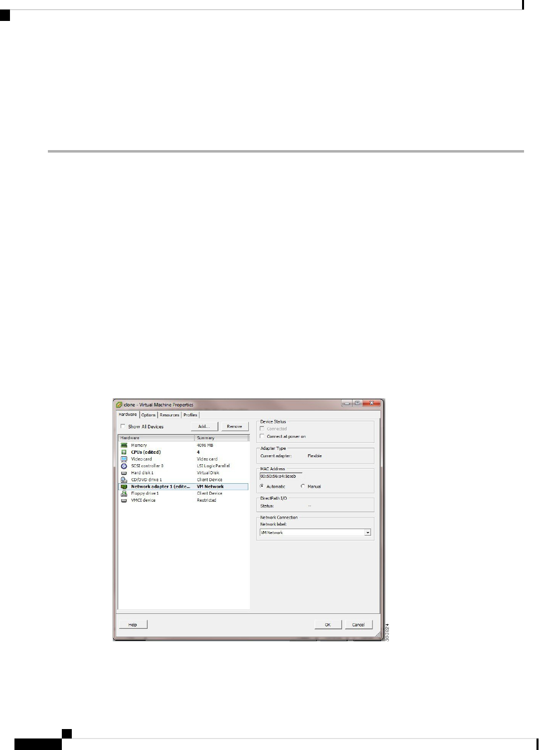
The Virtual Machine Properties page appears.
Step 8 Choose Network adapter, uncheck the Connected and Connect at power on check boxes, and click OK.
Step 9 Click Finish.
You can now power on this Cisco ISE node, configure the IP address and hostname, and connect it to the network.
What to do next
• Change the IP Address and Hostname of a Cloned Virtual Machine
• Connect a Cloned Cisco Virtual Machine to the Network
Change the IP Address and Hostname of a Cloned Virtual Machine
After you clone a Cisco ISE virtual machine (VM), you have to power it on and change the IP address and
hostname.
Before you begin
• Ensure that the Cisco ISE node is in the standalone state.
• Ensure that the network adapter on the newly cloned Cisco ISE VM is not connected when you power
on the machine. Uncheck the Connected and Connect at power on check boxes. Otherwise, if this node
comes up, it will have the same IP address as the source machine from which it was cloned.
Figure 9: Disconnecting the Network Adapter
Cisco Identity Services Engine Installation Guide, Release 3.1
66
Additional Installation Information
Change the IP Address and Hostname of a Cloned Virtual Machine

• Ensure that you have the IP address and hostname that you are going to configure for the newly cloned
VM as soon as you power on the machine. This IP address and hostname entry should be in the DNS
server. You cannot use "localhost" as the hostname for a node.
• Ensure that you have certificates for the Cisco ISE nodes based on the new IP address or hostname.
Procedure
Step 1 Right-click the newly cloned Cisco ISE VM and choose Power > Power On.
Step 2 Select the newly cloned Cisco ISE VM and click the Console tab.
Step 3 Enter the following commands on the Cisco ISE CLI:
configure terminal
hostname hostname
The hostname is the new hostname that you are going to configure. The Cisco ISE services are restarted.
Step 4 Enter the following commands:
interface gigabit 0
ip address ip_address netmask
The ip_address is the address that corresponds to the hostname that you entered in step 3 and netmask is the subnet mask
of the ip_address. The system will prompt you to restart the Cisco ISE services. See the Cisco Identity Services Engine
CLI Reference Guide, for the ip address and hostname commands.
Step 5 Enter Y to restart Cisco ISE services.
Connect a Cloned Cisco Virtual Machine to the Network
After you power on and change the ip address and hostname, you must connect the Cisco ISE node to the
network.
Step 1 Right-click the newly cloned Cisco ISE virtual machine (VM) and click Edit Settings.
Step 2 Click Network adapter in the Virtual Machine Properties dialog box.
Step 3 In the Device Status area, check the Connected and Connect at power on check boxes.
Step 4 Click OK.
Migrate Cisco ISE VM from Evaluation to Production
After evaluating the Cisco ISE release, you can migrate the from an evaluation system to a fully licensed
production system.
Before you begin
• When you move the VMware server to a production environment that supports a larger number of users,
be sure to reconfigure the Cisco ISE installation to the recommended minimum disk size or higher (up
to the allowed maximum of 2.4 TB).
Cisco Identity Services Engine Installation Guide, Release 3.1
67
Additional Installation Information
Connect a Cloned Cisco Virtual Machine to the Network

• Please not that you cannot migrate data to a production VM from a VM created with less than 300 GB
of disk space. You can only migrate data from VMs created with 300 GB or more disk space to a
production environment.
Step 1 Back up the configuration of the evaluation version.
Step 2 Ensure that your production VM has the required amount of disk space.
Step 3 Install a production deployment license.
Step 4 Restore the configuration to the production system.
Check Virtual Machine Performance On-Demand
You can run the show tech-support command from the CLI to check the VM performance at any point of
time. The output of this command will be similar to the following:
ise-vm123/admin# show tech | begin "disk IO perf"
Measuring disk IO performance
*****************************************
Average I/O bandwidth writing to disk device: 48 MB/second
Average I/O bandwidth reading from disk device: 193 MB/second
WARNING: VM I/O PERFORMANCE TESTS FAILED!
WARNING: The bandwidth writing to disk must be at least 50 MB/second,
WARNING: and bandwidth reading from disk must be at least 300 MB/second.
WARNING: This VM should not be used for production use until disk
WARNING: performance issue is addressed.
Disk I/O bandwidth filesystem test, writing 300 MB to /opt:
314572800 bytes (315 MB) copied, 7.81502 s, 40.3 MB/s
Disk I/O bandwidth filesystem read test, reading 300 MB from /opt:
314572800 bytes (315 MB) copied, 0.416897 s, 755 MB/s
Virtual Machine Resource Check from the Cisco ISE Boot Menu
You can check for virtual machine resources independent of Cisco ISE installation from the boot menu.
The CLI transcript appears as follows:
Cisco ISE Installation (Serial Console)
Cisco ISE Installation (Keyboard/Monitor)
System Utilities (Serial Console)
System Utilities (Keyboard/Monitor)
Use the arrow keys to select System Utilities (Serial Console) or System Utilities (Keyboard/Monitor) and
press Enter. The following screen appears:
Available System Utilities:
[1] Recover administrator password
[2] Virtual Machine Resource Check
[3] Perform System Erase
[q] Quit and reload
Enter option [1 - 3] q to Quit
Cisco Identity Services Engine Installation Guide, Release 3.1
68
Additional Installation Information
Check Virtual Machine Performance On-Demand

Enter 2 to check for VM resources. The output will be similar to the following:
*****
***** Virtual Machine host detected…
***** Hard disk(s) total size detected: 600 Gigabyte
***** Physical RAM size detected: 16267516 Kbytes
***** Number of network interfaces detected: 6
***** Number of CPU cores: 12
***** CPU Mhz: 2300.00
***** Verifying CPU requirement…
***** Verifying RAM requirement…
***** Writing disk partition table…
Linux KVM
KVM Virtualization Check
KVM virtualization requires virtualization support from the host processor; Intel VT-x for Intel processors
and AMD-V for AMD processors. Open a terminal window on the host and enter the cat /proc/cpuinfo
command. You must see either the vmx or the svm flag.
• For Intel VT-x:
# cat /proc/cpuinfo
flags: fpu vme de pse tsc msr pae mce cx8 apic sep mtrr pge mca cmov pat pse36 clflush
dts acpi mmx fxsr sse sse2 ss ht tm pbe syscall nx
pdpe1gb rdtscp lm constant_tsc arch_perfmon pebs bts rep_good nopl xtopology nonstop_tsc
aperfmperf eagerfpu pni pclmulqdq dtes64 monitor
ds_cpl vmx smx est tm2 ssse3 cx16 xtpr pdcm pcid dca sse4_1 sse4_2 x2apic popcnt
tsc_deadline_timer aes xsave avx lahf_lm arat epb xsaveopt
pln pts dtherm tpr_shadow vnmi flexpriority ept vpid
• For AMD-V:
# cat /proc/cpuinfo
flags: fpu tsc msr pae mce cx8 apic mtrr mca cmov pat pse36 clflush mmx fxsr sse sse2
ht syscall nx mmxext fxsr_opt rdtscp lm 3dnowext 3dnow
pni cx16 lahf_lm cmp_legacy svm cr8_legacy
Install Cisco ISE on KVM
This procedure explains how to create a KVM on RHEL and install Cisco ISE on it using the Virtual Machine
Manager (virt-manager).
If you choose to install Cisco ISE through the CLI, enter a command similar to the following one:
#virt-install --name=kvm-ise1 --arch=x86_64 --cpu=host --vcpus=2 --ram=4096
--os-type=linux --os-variant=rhel6 --hvm --virt-type=kvm
--cdrom=/home/admin/Desktop/ise-3.1.0.x.SPA.x86_64.iso
--disk=/home/libvirt-images/kvm-ise1.img,size=300
--network type=direct,model=virtio,source=eth2,source_mode=bridge
where ise-3.1.0.x.SPA.x86_64.iso is the name of the Cisco ISE ISO image.
Cisco Identity Services Engine Installation Guide, Release 3.1
69
Additional Installation Information
Linux KVM

Before you begin
Download the Cisco ISE ISO image to your local system.
Step 1 From the virt-manager, click New.
The Create a new virtual machine window appears.
Step 2 Click Local install media (ISO media or CDROM), and then click Forward.
Step 3 Click the Use ISO image radio button, click Browse, and select the ISO image from your local system.
a) Uncheck the Automatically detect operating system based on install media check box, choose Linux as the OS
type, choose supported Red Hat Enterprise Linux version, and click Forward.
Step 4 Choose the RAM and CPU settings and click Forward.
Step 5 Check the Enable storage for this virtual machine check box and choose the storage settings.
a) Click the Select managed or other existing storage radio button.
b) Click Browse.
c) From the Storage Pools navigation pane on the left, click disk FileSystem Directory.
d) Click New Volume.
A Create storage volume window appears.
e) Enter a name for the storage volume.
f) Choose raw from the Format drop-down list.
g) Enter the Maximum Capacity.
h) Click Finish.
i) Choose the volume that you created and click Choose Volume.
j) Click Forward.
The Ready to begin the installation screen appears.
Step 6 Check the Customize configuration before install check box.
Step 7 Under Advanced options, choose the macvtap as the source for the interface, choose Bridge in the Source mode
drop-down list, and click Finish.
a) (Optional) Click Add Hardware to add additional NICs.
Choose macvtap as the Network source and virtio as the Device model.
b) Click Finish.
Step 8 In the Virtual Machine screen, choose the disk device and under Advanced and Performance Options, choose the
following options, and click Apply.
ValueField
VirtIODisk bus
noneCache mode
nativeIO mode
Step 9 Click Begin Installation to install Cisco ISE on KVM.
The Cisco ISE installation boot menu appears.
Cisco Identity Services Engine Installation Guide, Release 3.1
70
Additional Installation Information
Install Cisco ISE on KVM

Step 10 At the system prompt, enter 1 to choose a monitor and keyboard port, or 2 to choose a console port, and press Enter.
The installer starts the installation of the Cisco ISE software on the VM. When the installation process finishes, the
console displays:
Type 'setup' to configure your appliance
localhost:
Step 11 At the system prompt, type setup and press Enter.
The Setup Wizard appears and guides you through the initial configuration.
You must add the following text to the VM settings XML file (under vcpu information) while installing Cisco
ISE on Ubuntu Linux KVM. Otherwise, serial number will not be properly displayed in the About ISE and
Server window:
<sysinfo type="smbios">
<system>
<entry name="product">KVM</entry>
</system>
<baseBoard>
<entry name="product">KVM</entry>
</baseBoard>
</sysinfo>
<OS>
<type arch="x86_64" machine="pc-q35-6.2">hvm</type>
<boot dev="hd"/>
<smbios mode="sysinfo"/>
</os>
Note
Microsoft Hyper-V
Create a Cisco ISE Virtual Machine on Hyper-V
This section describes how to create a new virtual machine, map the ISO image from the local disk to the
virtual CD/DVD drive, edit the CPU settings, and install Cisco ISE on Hyper-V.
Cisco ISE does not support the use of Multipath I/O (MPIO). Hence, the installation will fail if you are using
MPIO for the VM.
Note
Before you begin
Download the Cisco ISE ISO image from cisco.com to your local system.
Step 1 Launch Hyper-V Manager on a supported Windows server.
Cisco Identity Services Engine Installation Guide, Release 3.1
71
Additional Installation Information
Microsoft Hyper-V

Figure 10: Hyper-V Manager Console
Step 2 Right-click the VM host and click New > Virtual Machine.
Cisco Identity Services Engine Installation Guide, Release 3.1
72
Additional Installation Information
Create a Cisco ISE Virtual Machine on Hyper-V

Figure 11: Create New Virtual Machine
Step 3 Click Next to customize the VM configuration.
Cisco Identity Services Engine Installation Guide, Release 3.1
73
Additional Installation Information
Create a Cisco ISE Virtual Machine on Hyper-V

Figure 12: New Virtual Machine Wizard
Step 4 Enter a name for the VM and (optionally) choose a different path to store the VM, and click Next.
Cisco Identity Services Engine Installation Guide, Release 3.1
74
Additional Installation Information
Create a Cisco ISE Virtual Machine on Hyper-V

Figure 13: Specify Name and Location
Step 5 Click the Generation 1 radio button and click Next.
If you choose to create a Generation 2 ISE VM, ensure that you disable the Secure Boot option in the VM settings.
Cisco Identity Services Engine Installation Guide, Release 3.1
75
Additional Installation Information
Create a Cisco ISE Virtual Machine on Hyper-V

Figure 14: Specify Generation
Step 6 Specify the amount of memory to allocate to this VM, for example, 16000 MB, and click Next.
Cisco Identity Services Engine Installation Guide, Release 3.1
76
Additional Installation Information
Create a Cisco ISE Virtual Machine on Hyper-V
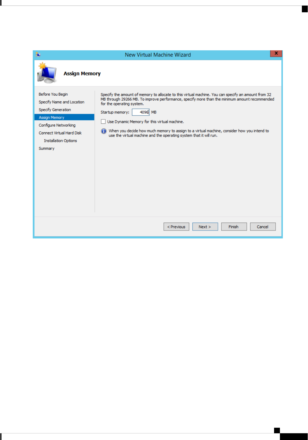
Figure 15: Assign Memory
Step 7 Select the network adapter and click Next.
Cisco Identity Services Engine Installation Guide, Release 3.1
77
Additional Installation Information
Create a Cisco ISE Virtual Machine on Hyper-V

Figure 16: Configure Networking
Step 8 Click the Create a virtual hard disk radio button and click Next.
Cisco Identity Services Engine Installation Guide, Release 3.1
78
Additional Installation Information
Create a Cisco ISE Virtual Machine on Hyper-V

Figure 17: Connect Virtual Hard Disk
Step 9 Click the Install an operating system from a bootable CD/DVD-ROM radio button.
a) From the Media area, click the Image file (.iso) radio button.
b) Click Browse to select the ISE ISO image from the local system and click Next.
Cisco Identity Services Engine Installation Guide, Release 3.1
79
Additional Installation Information
Create a Cisco ISE Virtual Machine on Hyper-V

Figure 18: Installation Options
Step 10 Click Finish.
Cisco Identity Services Engine Installation Guide, Release 3.1
80
Additional Installation Information
Create a Cisco ISE Virtual Machine on Hyper-V

Figure 19: Complete the New Virtual Machine Wizard
The Cisco ISE VM is created on Hyper-V.
Cisco Identity Services Engine Installation Guide, Release 3.1
81
Additional Installation Information
Create a Cisco ISE Virtual Machine on Hyper-V

Figure 20: New Virtual Machine created
Step 11 Select the VM and edit the VM settings.
a) Select Processor. Enter the number of virtual processors, for example, 6, and click OK.
Cisco Identity Services Engine Installation Guide, Release 3.1
82
Additional Installation Information
Create a Cisco ISE Virtual Machine on Hyper-V

Figure 21: Edit VM Settings
Step 12 Select the VM and click Connect to launch the VM console. Click the start button to turn on the Cisco ISE VM.
Cisco Identity Services Engine Installation Guide, Release 3.1
83
Additional Installation Information
Create a Cisco ISE Virtual Machine on Hyper-V

Figure 22: Start the Cisco ISE VM
The Cisco ISE installation menu appears.
Cisco Identity Services Engine Installation Guide, Release 3.1
84
Additional Installation Information
Create a Cisco ISE Virtual Machine on Hyper-V

Figure 23: CIsco ISE installation menu
Step 13 Enter 1 to install Cisco ISE using a keyboard and monitor.
Cisco Identity Services Engine Installation Guide, Release 3.1
85
Additional Installation Information
Create a Cisco ISE Virtual Machine on Hyper-V

Zero Touch Provisioning
Zero Touch Provisioning (ZTP) is an uninterrupted provisioning mechanism that automates Cisco ISE
installation, patching, hot patching, and infrastructure service enablement without manual intervention.
ZTP is available from Cisco ISE Release 3.1 onwards. There are two options available in ZTP:
• Mapping .img file: This method is supported in virtual machine (VM) automatic installations, appliances,
and OVA installations. It requires mandatory parameters such as hostname, IP address, IP netmask, IP
default gateway, DNS domain, primary name server, NTP server, system timezone, SSH, username, and
password to be configured. Optional parameters such as IPV6, patch, hot patch, services, and repository
details can also be configured. For more information, see ZTP Configuration Image File.
You cannot use an .img file for ZTP on Microsoft Hyper-V. You must use an
.iso file and create a Generation 2 VM for ZTP on Microsoft Hyper-V.
Note
• VM User Data: This method is supported in OVA and VM automatic installations. It is supported when
the user data is configured and requires mandatory parameters such as hostname, IP address, IP netmask,
IP default gateway, DNS domain, primary name server, NTP server, system timezone, SSH, username,
and password to be configured. Optional parameters such as IPV6, patch, hot patch, services, and repository
details can also be configured. For more information, see VM User Data.
• To track installation progress during the ZTP process, the serial console should be enabled for both the
VM and the appliance.
• A ZTP Configuration Image File is required.
Note
TFTP, HTTP, HTTPS, and NFS repositories are supported for installation of hot patches and patches on Cisco
ISE as part of the ZTP flow. The repositories created during the ZTP flow will not be visible or usable from
the Cisco ISE GUI. These repositories must have anonymous access (no username/password) for the ZTP
process to use them.
Note
Automatic Installation in Virtual Machine
The following subsections provide information about automatic installation in the VM.
These settings are applicable for all on-prem hypervisors:
• VMware
• Linux KVM
• Microsoft Hyper-V
• Nutanix AHV
Cisco Identity Services Engine Installation Guide, Release 3.1
86
Additional Installation Information
Zero Touch Provisioning

Automatic Installation in Virtual Machine Using the ZTP Configuration Image File
Step 1 Log in to the VMware client.
If you already have an existing VM setup, proceed to Step 2 and continue till Step 6. For a new VM setup,
go directly to Step 8.
Note
Step 2 For the VM to enter the BIOS setup mode, right-click the VM and select Edit Settings.
Step 3 Click the Options tab.
Step 4 Click Boot Options.
Step 5 In the Force BIOS Setup area, check the BIOS check box to enter the BIOS setup screen when the VM boots.
You must change the firmware from BIOS to EFI in the the boot mode of VM settings in order to boot
GPT partitions with 2 TB or more capacity.
Note
Step 6 Click OK.
Step 7 Ensure that the time zone and the correct boot order are set in BIOS/EFI:
a) If the VM is turned on, turn the system off.
b) Turn on the VM.
The system enters the BIOS setup mode.
c) In the main BIOS menu, using the arrow keys, navigate to the Date and Time field and press Enter.
d) Enter the time zone.
This time zone setting ensures that the reports, logs, and posture-agent log files from the various nodes in your
deployment are always synchronized with regard to the time stamps.
e) Using the arrow keys, navigate to the boot menu and press Enter.
f) Using the arrow keys, select the CD-ROM drive and press + to move the CD-ROM drive up the order.
g) Using the arrow keys, navigate to the Exit menu and choose Exit Saving Changes. (Press the Enter or Return key
to select your choice).
h) Choose Yes to save the changes and exit.
Step 8 Insert the Cisco ISE software DVD into the VMware ESXi host's primary CD/DVD drive.
Step 9 Insert the ZTP configuration image file into a secondary CD/DVD drive.
Step 10 Turn on the VM.
When the DVD starts, the console displays the following message:
Automatic installation starts in 150 seconds.
Available boot options:
[1] Cisco ISE Installation (Keyboard/Monitor)
[2] Cisco ISE Installation (Serial Console)
[3] System Utilities (Keyboard/Monitor)
[4] System Utilities (Serial Console)
[5] Hard Disk
Enter boot option and press <Enter>.
boot:
From Cisco ISE 3.1 onwards, pressing Enter without entering a boot option does not trigger the installation
using the hard disk option. Instead it triggers ZTP.
Note
Cisco Identity Services Engine Installation Guide, Release 3.1
87
Additional Installation Information
Automatic Installation in Virtual Machine Using the ZTP Configuration Image File

Step 11 After 150 seconds, the bootup process automatically starts if the prerequisites are met.
• Installation logs can be monitored only through the serial console because ZTP only works through
the serial console. It can be monitored from the VM console after the setup prompt is displayed.
• After the Cisco ISE services are started, you must manually unmount the ZTP configuration image
file from the CD/DVD.
Note
To leverage ZTP from the setup prompt (ZTP is carried out using the keyboard until the setup prompt apprears) perform
this procedure:
1. Install Cisco ISE manually till setup (using boot option 1 or 2) and create the ZTP configuration image file using the
steps described in the above procedure.
2. Power off the VM and map the ZTP configuration image file to the CD/DVD drive.
3. Power on the VM.
The setup details are picked up from the ZTP configuration file that is mapped to the CD/DVD drive.
Troubleshooting
Issue: If the automatic installation in the VM is triggered without mapping the .img file, after 150 seconds,
the installation fails with the following message:
***** The ZTP configuration image is missing or improper. Automatic installation flow
exited.
***** Power off and attach the proper ZTP configuration image or choose manual boot to
proceed.
Solution: This error message is seen only through the serial console and not on the VM console. If this happens
in an existing VM where Cisco ISE is already installed, the hard disk will not be formatted at this state. The
existing VM can be recovered by performing these steps: :
1. Turning off the VM.
2. Turning on the VM.
3. Pressing option 5 to boot from hard disk within 150 seconds to load the existing VM.
Issue: If the setup details are invalid in the configuration file, ZTP installation is stopped and the following
message is displayed on the VM Console:
==============================================================================
Cisco ISE Installation Failed
==============================================================================
Error: Sync with NTP server failed.
Check the setup details in your configuration image and reboot Cisco ISE
with proper ZTP configuration.
==============================================================================
Solution:
1. Create a new configuration .img file with valid details.
Cisco Identity Services Engine Installation Guide, Release 3.1
88
Additional Installation Information
Automatic Installation in Virtual Machine Using the ZTP Configuration Image File

2. Power off the VM.
3. Map the new valid image to the CD/DVD drive.
4. Power on the VM.
Installation begins from the setup.
Automatic Installation in Virtual Machine using VM User Data
Step 1 Log in to the VMware client.
If you already have an existing VM setup, proceed to Step 2 and continue till Step 6. For a new VM setup,
go directly to Step 8.
Note
Step 2 For the VM to enter the BIOS setup mode, right-click the VM and select Edit Settings.
Step 3 Click the Options tab.
Step 4 Click Boot Options.
Step 5 In the Force BIOS Setup area, check the BIOS check box to enter the BIOS setup screen when the VM boots.
You must change the firmware from BIOS to EFI in the the boot mode of VM settings in order to boot
GPT partitions with 2 TB or more capacity.
Note
Step 6 Click OK.
Step 7 Ensure that the time zone and the correct boot order are set in BIOS/EFI:
a) If the VM is turned on, turn the system off.
b) Turn on the VM.
The system enters the BIOS setup mode.
c) In the main BIOS menu, using the arrow keys, navigate to the Date and Time field and press Enter.
d) Enter the time zone.
This time zone setting ensures that the reports, logs, and posture-agent log files from the various nodes in your
deployment are always synchronized with regard to the time stamps.
e) Using the arrow keys, navigate to the boot menu and press Enter.
f) Using the arrow keys, select the CD-ROM drive and press + to move the CD-ROM drive up the order.
g) Using the arrow keys, navigate to the Exit menu and choose Exit Saving Changes (Press the Enter or Return key
to select your choice).
h) Choose Yes to save the changes and exit.
Step 8 Insert the Cisco ISE software DVD into the VMware ESXi host's primary CD/DVD drive.
Step 9 Configure the VM user data options.
If both the .img file and VM user data options are configured in the VM, the user data option is considered.
Note
Step 10 Turn on the VM.
When the DVD boots, the console displays the following message:
Automatic installation starts in 150 seconds.
Available boot options:
Cisco Identity Services Engine Installation Guide, Release 3.1
89
Additional Installation Information
Automatic Installation in Virtual Machine using VM User Data

[1] Cisco ISE Installation (Keyboard/Monitor)
[2] Cisco ISE Installation (Serial Console)
[3] System Utilities (Keyboard/Monitor)
[4] System Utilities (Serial Console)
[5] Hard Disk
Enter boot option and press <Enter>.
boot:
From Cisco ISE 3.1 onwards, pressing Enter without entering a boot option does not trigger the installation
using the hard disk option. Instead it triggers ZTP.
Note
Step 11 After 150 seconds, the bootup process automatically starts if the prerequisites are met.
• Installation logs can be monitored only through the serial console because ZTP works only through
the serial console. It can be monitored from the VM console after the setup prompt is displayed.
• After the Cisco ISE services are started, you must manually unmount the ZTP configuration image
file from the CD/DVD.
Note
To leverage ZTP from the setup prompt (ZTP is carried out using the keyboard until the setup prompt apprears) perform
this procedure:
1. Power off the VM.
2. Configure user-data option mentioned above.
3. Power on the VM .
The setup details are picked from the VM options.
Troubleshooting
Issue: If invalid setup details are entered in the user data option, the ZTP installation stops and the following
message is displayed on the VM console:
==============================================================================
Cisco ISE Installation Failed
==============================================================================
Error: Sync with NTP server failed.
Check the setup details in your configuration image and reboot Cisco ISE
with proper ZTP configuration.
==============================================================================
Solution:
1. Power off the VM.
2. Update user data details with valid data.
3. Power on the VM.
Installation begins from the setup.
Cisco Identity Services Engine Installation Guide, Release 3.1
90
Additional Installation Information
Automatic Installation in Virtual Machine using VM User Data

Automatic Installation in Appliance
The following subsections provide information about automatic installation in an appliance.
Automatic Installation in Appliance Using the ZTP Configuration Image File
Step 1 Log in to the SNS Appliance.
Step 2 Power off the host.
Step 3 Choose Compute > Remote Management > Virtual media.
Step 4 Map the Cisco ISE software ISO and the ZTP configuration image file to the primary CD/DVD drive and the secondary
CD/DVD drive.
Step 5 Power on the host.
When the appliance boots, the console displays the following message:
Please select boot device:
[1] Cisco ISE Installation (Keyboard/Monitor)
[2] Cisco ISE Installation (Serial Console)
[3] System Utilities (Keyboard/Monitor)
[4] System Utilities (Serial Console)
[5] Cisco ISE Installation Through ZTP Configuration (Serial Console)
Step 6 After 150 seconds, the start process automatically starts if the prerequisites are met.
• ZTP works on the SNS appliance through virtual media only.
• You must map the .img file in virtual media before mapping the ISO file.
Installation logs can be monitored through only the serial console because ZTP works through the serial
console. The logs can be monitored from the KVM console after the setup prompt is displayed.
• Automatic installation in appliance is supported only with the .img file.
Note
To leverage ZTP from the setup prompt (ZTP is done using the keyboard until the setup prompt apprears) perform the
following steps:
1. Install Cisco ISE manually till setup (using boot option 1 or 2) and create the ZTP configuration image file using the
steps described in the previous above.
2. Power off the host and map the ZTP configuration image file that is created, to the CD/DVD drive.
3. Power on the host.
The setup details are picked from the ZTP configuration file that is mapped to the CD/DVD drive.
Troubleshooting
Issue: If the automatic installation in the appliance is triggered without mapping the image file, after 150
seconds, the installation fails with the following message:
***** The ZTP configuration image is missing or improper. Automatic installation flow
exited.
Cisco Identity Services Engine Installation Guide, Release 3.1
91
Additional Installation Information
Automatic Installation in Appliance

***** Power off and attach the proper ZTP configuration image or choose manual boot to
proceed.
Solution:
1. Turn off the VM.
2. Turn on the VM.
3. Press option 5 to boot from hard disk within 150 seconds to load the existing VM.
Issue: If the setup details are invalid in the config file, ZTP installation is stopped and the following message
is displayed on the KVM console:
==============================================================================
Cisco ISE Installation Failed
==============================================================================
Error: Sync with NTP server failed.
Check the setup details in your configuration image and reboot Cisco ISE
with proper ZTP configuration.
==============================================================================
Solution:
1. Create a new configuration .img file with valid details.
2. Power off the VM.
3. Map the new valid image to the CD/DVD drive.
4. Power on the VM.
Installation begins from the setup.
Trigger Automatic Installation using UCS XML APIs
To trigger automatic installation:
The API URL and the request header are the same for all the methods:
Note
API URL
https://<ucs_server_ip>/nuova
Header
headers["Accept"] = "application/xml"
headers["Content-Type"] = "application/xml"
Step 1 Get the login session cookie for authentication.
The aaaLogin method is the login process and is required to begin a session. This action establishes the HTTP (or HTTPS)
session between the client and Cisco IMC. This session cookie is used in upcoming requests to maintain the login session.
Request
Cisco Identity Services Engine Installation Guide, Release 3.1
92
Additional Installation Information
Trigger Automatic Installation using UCS XML APIs

<aaaLogin inName='admin' inPassword='password'/>
Response
<aaaLogin cookie="" response="yes" outCookie="<real_cookie>" outRefreshPeriod="600" outPriv="admin"
outSessionId="17" outVersion="3.0(0.149)"> </aaaLogin>
Step 2 Map the Cisco ISE ISO.
This configures a Cisco ISE ISO file as a virtual media volume.
Request
<configConfMo cookie='<real_cookie>' dn='sys/svc-ext/vmedia-svc/vmmap-ISE_ISO' inHierarchical='false'>
<inConfig>
<commVMediaMap dn='sys/svc-ext/vmedia-svc/vmmap-ISE_ISO'
map=’nfs’
remoteFile=‘<ise_iso_file>’
remoteShare=‘<nfs_server_path>'
status='created' volumeName='ISE_ISO' />
</inConfig>
</configConfMo>
Response
<configConfMo dn="sys/svc-ext/vmedia-svc/vmmap-ISE_ISO"
cookie="<real_cookie>" response="yes">
<outConfig>
<commVMediaMap volumeName="ISE_ISO" map=“nfs”
remoteShare=‘<nfs_server_path>'
remoteFile="<ise_iso_file>"
mappingStatus="In Progress"
dn="sys/svc-ext/vmedia-svc/vmmap-ISE_ISO" status="created"/>
</outConfig>
</configConfMo>
Step 3 Map the configuration image file.
This configures a configuration image as a vMedia volume.
Request
<configConfMo cookie='<real_cookie>'
dn='sys/svc-ext/vmedia-svc/vmmap-CONFIG-IMG’ inHierarchical='false'>
<inConfig>
<commVMediaMap dn='sys/svc-ext/vmedia-svc/vmmap-CONFIG-IMG'
map=’nfs’
remoteFile=‘<config_img_file>’
remoteShare=‘<nfs_server_path>'
status='created' volumeName='CONFIG-IMG' />
</inConfig>
</configConfMo>
Response
<configConfMo dn="sys/svc-ext/vmedia-svc/vmmap-CONFIG-IMG"
cookie="<real_cookie>" response="yes">
<outConfig>
<commVMediaMap volumeName="CONFIG-IMG" map=“nfs”
remoteShare=‘<nfs_server_path>'
remoteFile="<config_img_file>"
mappingStatus="In Progress"
dn="sys/svc-ext/vmedia-svc/vmmap-CONFIG-IMG" status="created"/>
</outConfig>
</configConfMo>
Cisco Identity Services Engine Installation Guide, Release 3.1
93
Additional Installation Information
Trigger Automatic Installation using UCS XML APIs

Step 4 Set the CD-ROM at first place in the boot order.
This maps the Cisco ISE ISO file that is picked for installation during the power restart.
Request
<configConfMo cookie="<real_cookie>"
inHierarchical="true" dn="sys/rack-unit-1/boot-policy">
<inConfig>
<lsbootDef dn="sys/rack-unit-1/boot-policy" rebootOnUpdate=“yes”>
<lsbootVirtualMedia access="read-only" order=“1” dn="sys/rack-unit-1/boot-policy/vm-read-only"/>
</lsbootDef>
</inConfig>
</configConfMo>
Response
<configConfMo dn="sys/rack-unit-1/boot-policy" cookie="<real_cookie>" response="yes">
<outConfig>
<lsbootDef dn="sys/rack-unit-1/boot-policy" name="boot-policy" purpose="operational"
rebootOnUpdate="no" status="modified" >
</lsbootDef>
</outConfig>
</configConfMo>
Step 5 Enable the SoL (Serial over LAN).
This enables the SoL to view installation logs through Telnet.
Request
<configConfMo cookie='<real_cookie>'
dn='sys/rack-unit-1/sol-if'>
<inConfig>
<solIf dn='sys/rack-unit-1/sol-if' adminState=‘enable'/>
</inConfig>
</configConfMo>
Response
<configConfMo dn="sys/rack-unit-1/sol-if" cookie="<real_cookie>" response="yes">
<outConfig>
<solIf dn="sys/rack-unit-1/sol-if" adminState="enable" name="SoLInterface" speed="115200" comport="com0"
sshPort="2400" status="modified" ></solIf></outConfig>
</configConfMo>
Step 6 Power restart.
This triggers Cisco ISE installation in automatic mode.
Request
<configConfMo cookie='<real_cookie>' dn='sys/rack-unit-1'>
<inConfig><computeRackUnit
dn='sys/rack-unit-1'
adminPower='cycle-immediate'/>
</inConfig>
</configConfMo>
Response
<configConfMo dn="sys/rack-unit-1" cookie="<real_cookie>" response="yes">
<outConfig>
<computeRackUnit dn="sys/rack-unit-1" adminPower="policy" availableMemory="262144"
model="SNS-3695-K9" memorySpeed="2400" name="SNS-3695-K9" numOfAdaptors="0" numOfCores="12"
numOfCoresEnabled="12" numOfCpus="1" numOfEthHostIfs="0" numOfFcHostIfs="0" numOfThreads="24"
Cisco Identity Services Engine Installation Guide, Release 3.1
94
Additional Installation Information
Trigger Automatic Installation using UCS XML APIs

operPower="on" originalUuid="1935836B-B968-4031-8A98-7984F1D35449" presence="equipped" serverId="1"
serial="WZP2228085W" totalMemory="262144" usrLbl="" uuid="1935836B-B968-4031-8A98-7984F1D35449"
vendor="Cisco Systems Inc" cimcResetReason="graceful-reboot
" assetTag="Unknown" adaptorSecureUpdate="Enabled" resetComponents="components" storageResetStatus="NA"
vicResetStatus="NA" bmcResetStatus="NA" smartUsbAccess="disabled" smartUsbStatus="Disabled"
biosPostState="completed" status="modified" >
</computeRackUnit>
</outConfig>
</configConfMo>
Step 7 Logout to exit the session.
Request
<aaaLogout
cookie="<real_cookie>"
inCookie="<real_cookie>"
</aaaLogout>
Response:
<aaaLogout cookie="" response="yes" outStatus="success"> </aaaLogout>
For more information, see UCS API methods.
OVA Automatic Installation
The following sections provide information about automatic installation using the OVA.
Automatic OVA Installation Using the ZTP Configuration Image File
Step 1 Log in to the VMware client.
If you already have an existing VM setup, proceed to Step 2 and continue till Step 6. For a new VM setup,
go directly to Step 8.
Note
Step 2 For the VM to enter the BIOS setup mode, right-click the VM and select Edit Settings.
Step 3 Click the Options tab.
Step 4 Click Boot Options.
Step 5 In the Force BIOS Setup area, check the BIOS check box to enter the BIOS setup screen when the VM boots.
You must change the firmware from BIOS to EFI in the the boot mode of VM settings in order to boot
GPT partitions with 2 TB or more capacity.
Note
Step 6 Click OK.
Step 7 Ensure that the Coordinated Universal Time (UTC) and the correct boot order are set in BIOS:
a) If the VM is turned on, turn the system off.
b) Turn on the VM.
The system enters the BIOS setup mode.
c) In the main BIOS menu, using the arrow keys, navigate to the Date and Time field and press Enter.
d) Enter the UTC/Greenwich Mean Time (GMT) time zone.
Cisco Identity Services Engine Installation Guide, Release 3.1
95
Additional Installation Information
OVA Automatic Installation

This time zone setting ensures that the reports, logs, and posture-agent log files from the various nodes in your
deployment are always synchronized with regard to the time stamps.
e) Using the arrow keys, navigate to the boot menu and press Enter.
f) Using the arrow keys, select the CD-ROM drive and press + to move the CD-ROM drive up the order.
g) Using the arrow keys, navigate to the Exit menu and choose Exit Saving Changes (Press the Enter or Return key
to select your choice).
h) Choose Yes to save the changes and exit.
Step 8 Import the Cisco ISE OVA file into the VMware ESXi.
Step 9 Insert the ZTP configuration image file into the VMware ESXi host's primary CD/DVD drive.
Step 10 Turn on the virtual machine.
When the DVD boots, the console displays the following message:
Automatic installation starts in 150 seconds.
Available boot options:
[1] Cisco ISE Installation (Keyboard/Monitor)
[2] Cisco ISE Installation (Serial Console)
[3] System Utilities (Keyboard/Monitor)
[4] System Utilities (Serial Console)
[5] Hard Disk
Enter boot option and press <Enter>.
boot:
From Cisco ISE 3.1 onwards, pressing Enter without entering a boot option does not trigger the installation
using the hard disk option. Instead it triggers ZTP.
Note
Step 11 After 150 seconds, the bootup process automatically starts if the prerequisites are met.
• Installation logs can be monitored only through the serial console because ZTP works only through
the serial console. The logs can be monitored from the VM console after the setup prompt is displayed.
• After the Cisco ISE services are started, you must manually unmount the ZTP configuration image
file from the CD/DVD.
Note
To leverage ZTP from the setup prompt (ZTP is done using the keyboard until the setup prompt apprears) perform this
procedure:
1. Install Cisco ISE manually till setup (using boot option 1 or 2) and create the ZTP configuration image file using the
steps described in the above procedure.
2. Power off the VM.
3. Map the ZTP configuration image file to the CD/DVD drive.
4. Power on the VM.
The setup details are picked up from the ZTP configuration file that is mapped to the CD/DVD drive.
Troubleshooting
Issue: If the setup details are invalid in the configuration file, ZTP installation stops and the following message
is displayed on the VM console:
Cisco Identity Services Engine Installation Guide, Release 3.1
96
Additional Installation Information
Automatic OVA Installation Using the ZTP Configuration Image File

==============================================================================
Cisco ISE Installation Failed
==============================================================================
Error: Sync with NTP server failed.
Check the setup details in your configuration image and reboot Cisco ISE
with proper ZTP configuration.
==============================================================================
Solution: This can be resolved by performing the following steps:
1. Create a new configuration .img file with valid details.
2. Power off the VM.
3. Map the new valid image to the CD/DVD drive.
4. Power on the VM.
Installation begins from the setup.
OVA Automatic Installation Using the VM User Data
Step 1 Log in to the VMware client.
If you already have an existing VM setup, proceed to Step 2 and continue till Step 6. For a new VM setup,
go directly to Step 8.
Note
Step 2 For the VM to enter the BIOS setup mode, right-click the VM and select Edit Settings.
Step 3 Click the Options tab.
Step 4 Click Boot Options.
Step 5 In the Force BIOS Setup area, check the BIOS check box to enter the BIOS setup screen when the VM boots.
You must change the firmware from BIOS to EFI in the the boot mode of VM settings in order to boot
GPT partitions with 2 TB or more capacity.
Note
Step 6 Click OK.
Step 7 Ensure that the Coordinated Universal Time (UTC) and the correct boot order are set in BIOS:
a) If the VM is turned on, turn the system off.
b) Turn on the VM.
The system enters the BIOS setup mode.
c) In the main BIOS menu, using the arrow keys, navigate to the Date and Time field and press Enter.
d) Enter the UTC/Greenwich Mean Time (GMT) time zone.
This time zone setting ensures that the reports, logs, and posture-agent log files from the various nodes in your
deployment are always synchronized with regard to the time stamps.
e) Using the arrow keys, navigate to the boot menu and press Enter.
f) Using the arrow keys, select the CD-ROM drive and press + to move the CD-ROM drive up the order.
Cisco Identity Services Engine Installation Guide, Release 3.1
97
Additional Installation Information
OVA Automatic Installation Using the VM User Data

g) Using the arrow keys, navigate to the Exit menu and choose Exit Saving Changes (Press the Enter or Return key
to select your choice).
h) Choose Yes to save the changes and exit.
Step 8 Import the Cisco ISE OVA file into the VMware ESXi.
Step 9 Configure the VM user data options.
If both .img file and VM user data options are configured in the VM, the user data option is considered.
Note
Step 10 Turn on the VM.
When the DVD boots, the console displays the following message:
Automatic installation starts in 150 seconds.
Available boot options:
[1] Cisco ISE Installation (Keyboard/Monitor)
[2] Cisco ISE Installation (Serial Console)
[3] System Utilities (Keyboard/Monitor)
[4] System Utilities (Serial Console)
[5] Hard Disk
Enter boot option and press <Enter>.
boot:
From Cisco ISE 3.1 onwards, pressing Enter without entering a boot option does not trigger the installation
using the hard disk option. Instead it triggers ZTP.
Note
Step 11 After 150 seconds, the bootup process automatically starts if the prerequisites are met.
• Installation logs can be monitored only through the serial console because ZTP works only through
the serial console. It can be monitored from the VM console after the setup prompt is displayed.
• After the Cisco ISE services are started, you must manually unmount the ZTP configuration image
file from the CD/DVD.
Note
To leverage ZTP from the setup prompt (ZTP is carried out using the keyboard until the setup prompt apprears) perform
this procedure:
1. Power off the VM.
2. Configure user-data option mentioned above.
3. Power on the VM .
The setup details are picked from the VM options.
Troubleshooting
Issue: If invalid setup details are entered in the user data option, the ZTP installation stops and the following
message is displayed on the VM console:
==============================================================================
Cisco ISE Installation Failed
==============================================================================
Error: Sync with NTP server failed.
Cisco Identity Services Engine Installation Guide, Release 3.1
98
Additional Installation Information
OVA Automatic Installation Using the VM User Data

Check the setup details in your configuration image and reboot Cisco ISE
with proper ZTP configuration.
==============================================================================
Solution: This can be resolved by performing the following steps:
1. Power off the VM.
2. Update user data details with valid data.
3. Power on the VM.
Installation begins from the setup.
Creating the ZTP Configuration Image File
Create the ZTP configuration image file using the ./create_ztp_image.sh ise-ztp.conf ise-ztp.img command.
The script can be executed on RHEL, CentOS, or Ubuntu.
To skip the ICMP, DNS, and NTP checks, set the following flags to True in the configuration image file:
• ICMP: SkipIcmpChecks=true
• DNS: SkipDnsChecks=true
• NTP: SkipNtpChecks=true
create_ztp_image.sh
script creation
#!/bin/bash
###########################################################
# This script is used to generate ise ztp image with ztp
# configuration file.
#
# Need to pass ztp configuration file as input.
#
# Copyright (c) 2021 by Cisco Systems, Inc.
# All rights reserved.
# Note:
# To mount the image use below command
# mount ise_ztp_config.img /ztp
# To mount the image from cdrom
# mount -o ro /dev/sr1 /ztp
#############################################################
if [ -z "$1" ];then
echo "Usage:$0 <ise-ztp.conf> [out-ztp.img]"
exit 1
elif [ ! -f $1 ];then
echo "file $1 not exist"
exit 1
else
conf_file=$1
fi
if [ -z "$2" ] ;then
image=ise_config.img
else
image=$2
fi
mountpath=/tmp/ise_ztp
Cisco Identity Services Engine Installation Guide, Release 3.1
99
Additional Installation Information
Creating the ZTP Configuration Image File

ztplabel=ISE-ZTP
rm -fr $mountpath
mkdir -p $mountpath
dd if=/dev/zero of=$image bs=1k count=1440 > /dev/null 2>&1
if [ `echo $?` -ne 0 ];then
echo "Image creation failed\n"
exit 1
fi
mkfs.ext4 $image -L $ztplabel -F > /dev/null 2>&1
mount -o rw,loop $image $mountpath
cp $conf_file $mountpath/ise-ztp.conf
sync
umount $mountpath
sleep 1
# Check for automount and unmount
automountpath=$(mount | grep $ztplabel | awk '{print $3}')
if [ -n "$automountpath" ];then
umount $automountpath
fi
echo "Image created $image"
VM User Data
VM user data is supported from ESXi 6.5 and later for Cisco ISE installation.
Paste the content of the ise-ztp.conf file in the base64encode tool. Use the base64encode tool to get the
encoded string.
You have to enter the encoded base64 string in the VM along with the VM user data. In the VMware ESXi,
go to VM Options > Advanced > Configuration Parameters > Edit Configuration > guestinfo.ise.ztp =
[Value] Base Encoded ZTP Configuration to enter the string.
Cisco Identity Services Engine Installation Guide, Release 3.1
100
Additional Installation Information
VM User Data

CHAPTER 6
Installation Verification and Post-Installation
Tasks
• Log in to the Cisco ISE Web-Based Interface, on page 101
• Cisco ISE Configuration Verification, on page 103
• List of Post-Installation Tasks, on page 105
Log in to the Cisco ISE Web-Based Interface
When you log in to the Cisco ISE web-based interface for the first time, you will be using the preinstalled
Evaluation license.
We recommend that you use the Cisco ISE user interface to periodically reset your administrator login
password.
Note
For security reasons, we recommend that you log out when you complete your administrative session. If you
do not log out, the Cisco ISE web-based web interface logs you out after 30 minutes of inactivity, and does
not save any unsubmitted configuration data.
Caution
For information about the validated browsers, see "Validated Browsers" section in the Cisco ISE Release
Notes.
If Cisco ISE is installed in the cloud or using the ZTP process, you will be prompted to change the web-based
admin user password during the first login.
Note
Step 1 After the Cisco ISE appliance reboot has completed, launch one of the supported web browsers.
Step 2 In the Address field, enter the IP address (or hostname) of the Cisco ISE appliance by using the following format and
press Enter.
Cisco Identity Services Engine Installation Guide, Release 3.1
101

https://<IP address or host name>/admin/
Step 3 Enter a username and password that you defined during setup.
Step 4 Click Login.
Differences Between CLI Admin and Web-Based Admin Users Tasks
The username and password that you configure when using the Cisco ISE setup program are intended to be
used for administrative access to the Cisco ISE CLI and the Cisco ISE web interface. The administrator that
has access to the Cisco ISE CLI is called the CLI-admin user. By default, the username for the CLI-admin
user is admin and the password is user-defined during the setup process. There is no default password.
You can initially access the Cisco ISE web interface by using the CLI-admin user’s username and password
that you defined during the setup process. There is no default username and password for a web-based admin.
The CLI-admin user is copied to the Cisco ISE web-based admin user database. Only the first CLI-admin
user is copied as the web-based admin user. You should keep the CLI- and web-based admin user stores
synchronized, so that you can use the same username and password for both admin roles.
The Cisco ISE CLI-admin user has different rights and capabilities than the Cisco ISE web-based admin user
and can perform other administrative tasks.
Table 13: Tasks Performed by CLI-Admin and Web-Based Admin Users
TasksAdmin User Type
• Back up the Cisco ISE application data.
• Display any system, application, or diagnostic logs on the Cisco ISE
appliance.
• Apply Cisco ISE software patches, maintenance releases, and
upgrades.
• Set the NTP server configuration.
Both CLI-Admin and
Web-Based Admin
• Start and stop the Cisco ISE application software.
• Reload or shut down the Cisco ISE appliance.
• Reset the web-based admin user in case of a lockout.
• Access the ISE CLI.
CLI-Admin only
Create a CLI Admin
Cisco ISE allows you to create additional CLI-admin user accounts other than the one you created during the
setup process. To protect the CLI-admin user credentials, create the minimum number of CLI-admin users
needed to access the Cisco ISE CLI.
You can add the CLI-admin user by using the following command in the configuration mode:
Cisco Identity Services Engine Installation Guide, Release 3.1
102
Installation Verification and Post-Installation Tasks
Differences Between CLI Admin and Web-Based Admin Users Tasks

username <username> password [plain/hash] <password> role admin
Create a Web-Based Admin
For first-time web-based access to Cisco ISE system, the administrator username and password is the same
as the CLI-based access that you configured during setup.
To add an admin user:
1. In the Cisco ISE GUI, click the Menu icon ( ) and choose Administration > System > Admin Access
> Administrators > Admin Users.
2. Choose Add > Create an Admin User.
3. Enter the name, password, admin group, and the other required details.
4. Click Submit.
Reset a Disabled Password Due to Administrator Lockout
An administrator can enter an incorrect password enough times to disable the account. The minimum and
default number of attempts is five.
Use these instructions to reset the administrator user interface password with the application reset-passwd
ise command in the Cisco ISE CLI. It does not affect the CLI password of the administrator. After you
successfully reset the administrator password, the credentials are immediately active and you can log in without
having to reboot the system. .
Cisco ISE adds a log entry in the Administrator Logins window. To view this window, click the Menu icon
( ) and choose Operations > Reports > Reports > Audit > Administrator Logins. The credentials for
that administrator ID is suspended until you reset the password associated with that administrator ID.
Step 1 Access the direct-console CLI and enter:
application reset-passwd ise administrator_ID
Step 2 Specify and confirm a new password that is different from the previous two passwords that were used for this administrator
ID:
Enter new password:
Confirm new password:
Password reset successfully
Cisco ISE Configuration Verification
There are two methods that each use a different set of username and password credentials for verifying Cisco
ISE configuration by using a web browser and CLI.
Cisco Identity Services Engine Installation Guide, Release 3.1
103
Installation Verification and Post-Installation Tasks
Create a Web-Based Admin

A CLI-admin user and a web-based admin user credentials are different in Cisco ISE.
Note
Verify Configuration Using a Web Browser
Step 1 After the Cisco ISE appliance reboot has completed, launch one of the supported web browsers.
Step 2 In the Address field, enter the IP address (or host name) of the Cisco ISE appliance using the following format and
press Enter.
Step 3 In the Cisco ISE Login page, enter the username and password that you have defined during setup and click Login.
For example, entering https://10.10.10.10/admin/ displays the Cisco ISE Login page.
https://<IP address or host name>/admin/
For first-time web-based access to Cisco ISE system, the administrator username and password is the same
as the CLI-based access that you configured during setup.
Note
Step 4 Use the Cisco ISE dashboard to verify that the appliance is working correctly.
What to do next
By using the Cisco ISE web-based user interface menus and options, you can configure the Cisco ISE system
to suit your needs. For details on configuring Cisco ISE, see Cisco Identity Services Engine Administrator
Guide.
Verify Configuration Using the CLI
Before you begin
Download and install the latest Cisco ISE patch to keep Cisco ISE up-to-date.
Step 1 After the Cisco ISE appliance reboot has completed, launch a supported product, such as PuTTY, for establishing a Secure
Shell (SSH) connection to a Cisco ISE appliance.
Step 2 In the Host Name (or IP Address) field, enter the hostname (or the IP address in dotted decimal format of the Cisco ISE
appliance) and click Open.
Step 3 At the login prompt, enter the CLI-admin username (admin is the default) that you configured during setup and press Enter.
Step 4 At the password prompt, enter the CLI-admin password that you configured during setup (this is user-defined and there
is no default) and press Enter.
Step 5 At the system prompt, enter show application version ise and press Enter.
Step 6 To check the status of the Cisco ISE processes, enter show application status ise and press Enter.
The console output appears as shown below:
ise-server/admin# show application status ise
Cisco Identity Services Engine Installation Guide, Release 3.1
104
Installation Verification and Post-Installation Tasks
Verify Configuration Using a Web Browser

ISE PROCESS NAME STATE PROCESS ID
--------------------------------------------------------------------
Database Listener running 4930
Database Server running 66 PROCESSES
Application Server running 8231
Profiler Database running 6022
ISE Indexing Engine running 8634
AD Connector running 9485
M&T Session Database running 3059
M&T Log Collector running 9271
M&T Log Processor running 9129
Certificate Authority Service running 8968
EST Service running 18887
SXP Engine Service disabled
TC-NAC Docker Service disabled
TC-NAC MongoDB Container disabled
TC-NAC RabbitMQ Container disabled
TC-NAC Core Engine Container disabled
VA Database disabled
VA Service disabled
pxGrid Infrastructure Service disabled
pxGrid Publisher Subscriber Service disabled
pxGrid Connection Manager disabled
pxGrid Controller disabled
PassiveID Service disabled
DHCP Server (dhcpd) disabled
DNS Server (named) disabled
List of Post-Installation Tasks
After you install Cisco ISE, you must perform the following mandatory tasks:
Table 14: Mandatory Post-Installation Tasks
Link in the Administration GuideTask
See the section "Software Patch Installation
Guidelines" in Chapter "Maintain and Monitor" in the
Cisco ISE Administrator Guide for your release.
Apply the latest patches, if any
See the Cisco ISE Ordering Guide for more
information. See Chapter "Licensing" in the Cisco
ISE Administrator Guide for your release.
Install Licenses
See the section "Certificate Management in Cisco
ISE" in Chapter "Basic Setup" in the Cisco ISE
Administrator Guide for your release.
Install Certificates
See the section "Create Repositories" in Chapter
"Maintain and Monitor" in the Cisco ISE
Administrator Guide for your release
Create Repository for Backups
Cisco Identity Services Engine Installation Guide, Release 3.1
105
Installation Verification and Post-Installation Tasks
List of Post-Installation Tasks

Link in the Administration GuideTask
See the section "Schedule a Backup" in Chapter
"Maintain and Monitor" in the Cisco ISE
Administrator Guide for your release.
Configure Backup Schedules
See the section "Cisco ISE Distributed Deployment"
in Chapter "Deployment" in the Cisco ISE
Administrator Guide for your release.
Deploy Cisco ISE personas
Cisco Identity Services Engine Installation Guide, Release 3.1
106
Installation Verification and Post-Installation Tasks
List of Post-Installation Tasks

CHAPTER 7
Common System Maintenance Tasks
• Bond Ethernet Interfaces for High Availability, on page 107
• Reset a Lost, Forgotten, or Compromised Password Using a DVD, on page 112
• Reset a Disabled Password Due to Administrator Lockout, on page 113
• Return Material Authorization, on page 113
• Change the IP Address of a Cisco ISE Appliance, on page 113
• View Installation and Upgrade History, on page 114
• Perform a System Erase, on page 115
Bond Ethernet Interfaces for High Availability
Cisco ISE supports bonding of two Ethernet interfaces into a single virtual interface to provide high availability
for the physical interfaces. This feature is called Network Interface Card (NIC) bonding or NIC teaming.
When two interfaces are bonded, the two NICs appear to be a single device with a single MAC address.
The NIC bonding feature in Cisco ISE does not support load balancing or link aggregation features. Cisco
ISE supports only the high availability feature of NIC bonding.
The bonding of interfaces ensures that Cisco ISE services are not affected when there is:
• Physical interface failure
• Loss of switch port connectivity (shut or failure)
• Switch line card failure
When two interfaces are bonded, one of the interfaces becomes the primary interface and the other becomes
the backup interface. When two interfaces are bonded, all traffic normally flows through the primary interface.
If the primary interface fails for some reason, the backup interface takes over and handles all the traffic. The
bond takes the IP address and MAC address of the primary interface.
When you configure the NIC bonding feature, Cisco ISE pairs fixed physical NICs to form bonded NICs.
The following table outlines which NICs can be bonded together to form a bonded interface.
Cisco Identity Services Engine Installation Guide, Release 3.1
107

Table 15: Physical NICs Bonded Together to Form an Interface
Bonded NIC NameRole in Bonded NICLinux Physical NIC NameCisco ISE Physical NIC
Name
Bond 0PrimaryEth0Gigabit Ethernet 0
BackupEth1Gigabit Ethernet 1
Bond 1
PrimaryEth2Gigabit Ethernet 2
BackupEth3Gigabit Ethernet 3
Bond 2
PrimaryEth4Gigabit Ethernet 4
BackupEth5Gigabit Ethernet 5
Supported Platforms
The NIC bonding feature is supported on all supported platforms and node personas. The supported platforms
include:
• SNS hardware appliances - Bond 0, 1, and 2
• VMware virtual machines - Bond 0, 1, and 2 (if six NICs are available to the virtual machine)
• Linux KVM nodes - Bond 0, 1, and 2 (if six NICs are available to the virtual machine)
Guidelines for Bonding Ethernet Interfaces
• As Cisco ISE supports up to six Ethernet interfaces, it can have only three bonds, bond 0, bond 1, and
bond 2.
• You cannot change the interfaces that are part of a bond or change the role of the interface in a bond.
See the above table for information on which NICs can be bonded together and their role in the bond.
• The Eth0 interface acts as both the management interface as well as the runtime interface. The other
interfaces act as runtime interfaces.
• Before you create a bond, the primary interface (primary NIC) must be assigned an IP address. The Eth0
interface must be assigned an IPv4 address before you create bond 0. Similarly, before you create bond
1 and 2, Eth2 and Eth4 interfaces must be assigned an IPv4 or IPv6 address, respectively.
• Before you create a bond, if the backup interface (Eth1, Eth3, and Eth5 ) has an IP address assigned,
remove the IP address from the backup interface. The backup interface should not be assigned an IP
address.
• You can choose to create only one bond (bond 0) and allow the rest of the interfaces to remain as is. In
this case, bond 0 acts as the management interface and runtime interface, and the rest of the interfaces
act as runtime interfaces.
• You can change the IP address of the primary interface in a bond. The new IP address is assigned to the
bonded interface because it assumes the IP address of the primary interface.
Cisco Identity Services Engine Installation Guide, Release 3.1
108
Common System Maintenance Tasks
Supported Platforms

• When you remove the bond between two interfaces, the IP address assigned to the bonded interface is
assigned back to the primary interface.
• If you want to configure the NIC bonding feature on a Cisco ISE node that is part of a deployment, you
must deregister the node from the deployment, configure NIC bonding, and then register the node back
to the deployment.
• If a physical interface that acts as a primary interface in a bond (Eth0, Eth2, or Eth4 interface) has static
route configured, the static routes are automatically updated to operate on the bonded interface instead
of the physical interface.
Configure NIC Bonding
You can configure NIC bonding from the Cisco ISE CLI. The following procedure explains how you can
configure bond 0 between Eth0 and Eth1 interfaces.
Before you begin
If a physical interface that acts as a backup interface (for example, Eth1, Eth3, Eth5 interfaces), is configured
with an IP address, you must remove the IP address from the backup interface. The backup interface should
not be assigned an IP address.
Step 1 Log in to Cisco ISE CLI with your administrator account.
Step 2 Enter configure terminal to enter the configuration mode.
Step 3 Enter the interface GigabitEthernet 0 command.
Step 4 Enter the backup interface GigabitEthernet 1 command.
The console displays:
% Warning: IP address of interface eth1 will be removed once NIC bonding is enabled. Are you sure
you want to proceed? Y/N [N]:
Step 5 Enter Y and press Enter.
Bond 0 is now configured. Cisco ISE restarts automatically. Wait for some time to ensure that all the services are up and
running successfully. Enter the show application status ise command from the CLI to check if all the services are running.
ise/admin# configure terminal
Enter configuration commands, one per line. End with CNTL/Z.
ise/admin(config)# interface gigabitEthernet 0
ise/admin(config-GigabitEthernet)# backup interface gigabitEthernet 1
Changing backup interface configuration may cause ISE services to restart.
Are you sure you want to proceed? Y/N [N]: Y
Stopping ISE Monitoring & Troubleshooting Log Collector...
Stopping ISE Monitoring & Troubleshooting Log Processor...
ISE PassiveID Service is disabled
ISE pxGrid processes are disabled
Stopping ISE Application Server...
Stopping ISE Certificate Authority Service...
Stopping ISE EST Service...
ISE Sxp Engine Service is disabled
Stopping ISE Profiler Database...
Stopping ISE Indexing Engine...
Stopping ISE Monitoring & Troubleshooting Session Database...
Cisco Identity Services Engine Installation Guide, Release 3.1
109
Common System Maintenance Tasks
Configure NIC Bonding

Stopping ISE AD Connector...
Stopping ISE Database processes...
Starting ISE Monitoring & Troubleshooting Session Database...
Starting ISE Profiler Database...
Starting ISE Application Server...
Starting ISE Indexing Engine...
Starting ISE Certificate Authority Service...
Starting ISE EST Service...
Starting ISE Monitoring & Troubleshooting Log Processor...
Starting ISE Monitoring & Troubleshooting Log Collector...
Starting ISE AD Connector...
Note: ISE Processes are initializing. Use 'show application status ise'
CLI to verify all processes are in running state.
ise/admin(config-GigabitEthernet)#
Verify NIC Bonding Configuration
To verify if NIC bonding feature is configured, run the show running-config command from the Cisco ISE
CLI. You will see an output similar to the following:
!
interface GigabitEthernet 0
ipv6 address autoconfig
ipv6 enable
backup interface GigabitEthernet 1
ip address 192.168.118.214 255.255.255.0
!
In the output above, "backup interface GigabitEthernet 1" indicates that NIC bonding is configured on Gigabit
Ethernet 0, with Gigabit Ethernet 0 being the primary interface and Gigabit Ethernet 1 being the backup
interface. Also, the ADE-OS configuration does not display an IP address on the backup interface in the
running config, even though the primary and backup interfaces effectively have the same IP address.
You can also run the show interface command to see the bonded interfaces.
ise/admin# show interface
bond0: flags=5187<UP,BROADCAST,RUNNING,PRIMARY,MULTICAST> mtu 1500
inet 10.126.107.60 netmask 255.255.255.0 broadcast 10.126.107.255
inet6 fe80::8a5a:92ff:fe88:4aea prefixlen 64 scopeid 0x20<link>
ether 88:5a:92:88:4a:ea txqueuelen 0 (Ethernet)
RX packets 1726027 bytes 307336369 (293.0 MiB)
RX errors 0 dropped 844 overruns 0 frame 0
TX packets 1295620 bytes 1073397536 (1023.6 MiB)
TX errors 0 dropped 0 overruns 0 carrier 0 collisions 0
GigabitEthernet 0
flags=6211<UP,BROADCAST,RUNNING,SUBORDINATE,MULTICAST> mtu 1500
ether 88:5a:92:88:4a:ea txqueuelen 1000 (Ethernet)
RX packets 1726027 bytes 307336369 (293.0 MiB)
RX errors 0 dropped 844 overruns 0 frame 0
TX packets 1295620 bytes 1073397536 (1023.6 MiB)
TX errors 0 dropped 0 overruns 0 carrier 0 collisions 0
device memory 0xfab00000-fabfffff
GigabitEthernet 1
flags=6211<UP,BROADCAST,RUNNING,SUBORDINATE,MULTICAST> mtu 1500
Cisco Identity Services Engine Installation Guide, Release 3.1
110
Common System Maintenance Tasks
Verify NIC Bonding Configuration

ether 88:5a:92:88:4a:ea txqueuelen 1000 (Ethernet)
RX packets 0 bytes 0 (0.0 B)
RX errors 0 dropped 0 overruns 0 frame 0
TX packets 0 bytes 0 (0.0 B)
TX errors 0 dropped 0 overruns 0 carrier 0 collisions 0
device memory 0xfaa00000-faafffff
Remove NIC Bonding
Use the no form of the backup interface command to remove a NIC bond.
Before you begin
Step 1 Log in to Cisco ISE CLI with your administrator account.
Step 2 Enter configure terminal to enter the configuration mode.
Step 3 Enter the interface GigabitEthernet 0 command.
Step 4 Enter the no backup interface GigabitEthernet 1 command.
% Notice: Bonded Interface bond 0 has been removed.
Step 5 Enter Y and press Enter.
Bond 0 is now removed. Cisco ISE restarts automatically. Wait for some time to ensure that all the services are up and
running successfully. Enter the show application status ise command from the CLI to check if all the services are running.
ise/admin# configure terminal
Enter configuration commands, one per line. End with CNTL/Z.
ise/admin(config)# interface gigabitEthernet 0
ise/admin(config-GigabitEthernet)# no backup interface gigabitEthernet 1
Changing backup interface configuration may cause ISE services to restart.
Are you sure you want to proceed? Y/N [N]: Y
Stopping ISE Monitoring & Troubleshooting Log Collector...
Stopping ISE Monitoring & Troubleshooting Log Processor...
ISE PassiveID Service is disabled
ISE pxGrid processes are disabled
Stopping ISE Application Server...
Stopping ISE Certificate Authority Service...
Stopping ISE EST Service...
ISE Sxp Engine Service is disabled
Stopping ISE Profiler Database...
Stopping ISE Indexing Engine...
Stopping ISE Monitoring & Troubleshooting Session Database...
Stopping ISE AD Connector...
Stopping ISE Database processes...
Starting ISE Monitoring & Troubleshooting Session Database...
Starting ISE Profiler Database...
Starting ISE Application Server...
Starting ISE Indexing Engine...
Starting ISE Certificate Authority Service...
Starting ISE EST Service...
Starting ISE Monitoring & Troubleshooting Log Processor...
Starting ISE Monitoring & Troubleshooting Log Collector...
Starting ISE AD Connector...
Note: ISE Processes are initializing. Use 'show application status ise'
CLI to verify all processes are in running state.
Cisco Identity Services Engine Installation Guide, Release 3.1
111
Common System Maintenance Tasks
Remove NIC Bonding

ise/admin(config-GigabitEthernet)#
Reset a Lost, Forgotten, or Compromised Password Using a DVD
Before you begin
Make sure you understand the following connection-related conditions that can cause a problem when
attempting to use the Cisco ISE Software DVD to start up a Cisco ISE appliance:
• You have a terminal server associated with the serial console connection to the Cisco ISE appliance that
is set to exec. Setting it to no exec allows you to use a keyboard and video monitor connection and a
serial console connection.
• You have a keyboard and video monitor connection to the Cisco ISE appliance (this can be either a
remote keyboard and a video monitor connection or a VMware vSphere client console connection).
• You have a serial console connection to the Cisco ISE appliance.
Step 1 Ensure that the Cisco ISE appliance is powered up.
Step 2 Insert the Cisco ISE Software DVD.
Step 3 Use the arrow keys to select System Utilities (Serial Console) if you use a local serial console port connection or select
System Utilities (Keyboard/Monitor) if you use a keyboard and video monitor connection to the appliance, and press
Enter.
The system displays the ISO utilities menu as shown below.
Available System Utilities:
[1] Recover Administrator Password
[2] Virtual Machine Resource Check
[3] Perform System Erase
[q] Quit and reload
Enter option [1 - 3] q to Quit:
Step 4 Enter 1 to recover the administrator password.
The console displays:
Admin Password Recovery
This utility will reset the password for the specified ADE-OS administrator.
At most the first five administrators will be listed. To cancel without
saving changes, enter [q] to Quit and return to the utilities menu.
[1]:admin
[2]:admin2
[3]:admin3
[4]:admin4
Enter choice between [1 - 4] or q to Quit: 2
Password:
Verify password:
Cisco Identity Services Engine Installation Guide, Release 3.1
112
Common System Maintenance Tasks
Reset a Lost, Forgotten, or Compromised Password Using a DVD

Save change and reboot? [Y/N]:
Step 5 Enter the number corresponding to the admin user whose password you want to reset.
Step 6 Enter the new password and verify it.
Step 7 Enter Y to save the changes.
Reset a Disabled Password Due to Administrator Lockout
An administrator can enter an incorrect password enough times to disable the account. The minimum and
default number of attempts is five.
Use these instructions to reset the administrator user interface password with the application reset-passwd
ise command in the Cisco ISE CLI. It does not affect the CLI password of the administrator. After you
successfully reset the administrator password, the credentials are immediately active and you can log in without
having to reboot the system. .
Cisco ISE adds a log entry in the Administrator Logins window. To view this window, click the Menu icon
( ) and choose Operations > Reports > Reports > Audit > Administrator Logins. The credentials for
that administrator ID is suspended until you reset the password associated with that administrator ID.
Step 1 Access the direct-console CLI and enter:
application reset-passwd ise administrator_ID
Step 2 Specify and confirm a new password that is different from the previous two passwords that were used for this administrator
ID:
Enter new password:
Confirm new password:
Password reset successfully
Return Material Authorization
In case of a Return Material Authorization (RMA), if you are replacing individual components on an SNS
server, be sure to reimage the appliance before you install Cisco ISE. Contact Cisco TAC for assistance.
Change the IP Address of a Cisco ISE Appliance
Before you begin
• Ensure that the Cisco ISE node is in a standalone state before you change the IP address. If the node is
part of a distributed deployment, deregister the node from the deployment and make it a standalone node.
Cisco Identity Services Engine Installation Guide, Release 3.1
113
Common System Maintenance Tasks
Reset a Disabled Password Due to Administrator Lockout

• Do not use the no ip address command when you change the Cisco ISE appliance IP address.
Step 1 Log in to the Cisco ISE CLI.
Step 2 Enter the following commands:
a) configure terminal
b) interface GigabitEthernet 0
c) ip address new_ip_address new_subnet_mask
The system prompts you for the IP address change. Enter Y. A screen similar to the following one appears.
ise-13-infra-2/admin(config-GigabitEthernet)# ip address a.b.c.d 255.255.255.0
% Changing the IP address might cause ISE services to restart
Continue with IP address change? Y/N [N]: y
Stopping ISE Monitoring & Troubleshooting Log Collector...
Stopping ISE Monitoring & Troubleshooting Log Processor...
Stopping ISE Identity Mapping Service...
Stopping ISE pxGrid processes...
Stopping ISE Application Server...
Stopping ISE Certificate Authority Service...
Stopping ISE Profiler Database...
Stopping ISE Monitoring & Troubleshooting Session Database...
Stopping ISE AD Connector...
Stopping ISE Database processes...
Starting ISE Monitoring & Troubleshooting Session Database...
Starting ISE Profiler Database...
Starting ISE pxGrid processes...
Starting ISE Application Server...
Starting ISE Certificate Authority Service...
Starting ISE Monitoring & Troubleshooting Log Processor...
Starting ISE Monitoring & Troubleshooting Log Collector...
Starting ISE Identity Mapping Service...
Starting ISE AD Connector...
Note: ISE Processes are initializing. Use 'show application status ise'
CLI to verify all processes are in running state.
Cisco ISE prompts you to restart the system.
Step 3 Enter Y to restart the system.
View Installation and Upgrade History
Cisco ISE provides a Command Line Interface (CLI) command to view the details of installation, upgrade,
and uninstallation of Cisco ISE releases and patches. The show version history command provides the
following details:
• Date—Date and time at which the installation or uninstallation was performed
• Application—Cisco ISE application
• Version—Version that was installed or removed.
• Action—Installation, Uninstallation, Patch Installation, or Patch Uninstallation
Cisco Identity Services Engine Installation Guide, Release 3.1
114
Common System Maintenance Tasks
View Installation and Upgrade History

• Bundle Filename—Name of the bundle that was installed or removed
• Repository—Repository from which the Cisco ISE application bundle was installed. Not applicable for
uninstallation.
Step 1 Log in to the Cisco ISE CLI.
Step 2 Enter the following command: show version history.
The following output appears:
ise/admin# show version history
---------------------------------------------
Install Date: Fri Nov 30 21:48:58 UTC 2021
Application: ise
Version: 3.1.0.xxx
Install type: Application Install
Bundle filename: ise.tar.gz
Repository: SystemDefaultPkgRepos
ise/admin#
Perform a System Erase
You can perform a system erase to securely erase all information from your Cisco ISE appliance or VM. This
option to perform a system erase ensures that Cisco ISE is compliant with the NIST Special Publication 800-88
data destruction standards.
Before you begin
Make sure you understand the following connection-related conditions that can cause a problem when
attempting to use the Cisco ISE Software DVD to start up a Cisco ISE appliance:
• You have a terminal server associated with the serial console connection to the Cisco ISE appliance that
is set to exec. Setting it to no exec allows you to use a KVM connection and a serial console connection.
• You have a keyboard and video monitor (KVM) connection to the Cisco ISE appliance (this can be either
a remote KVM or a VMware vSphere client console connection).
• You have a serial console connection to the Cisco ISE appliance.
Step 1 Ensure that the Cisco ISE appliance is powered up.
Step 2 Insert the Cisco ISE Software DVD.
Step 3 Use the arrow keys to select System Utilities (Serial Console), and press Enter.
The system displays the ISO utilities menu as shown below:
Available System Utilities:
Cisco Identity Services Engine Installation Guide, Release 3.1
115
Common System Maintenance Tasks
Perform a System Erase

[1] Recover administrator password
[2] Virtual Machine Resource Check
[3] System Erase
[q] Quit and reload
Enter option [1 - 3] q to Quit:
Step 4 Enter 3 to perform a system erase.
The console displays:
********** W A R N I N G **********
THIS UTILITY WILL PERFORM A SYSTEM ERASE ON THE DISK DEVICE(S). THIS PROCESS CAN TAKE UP TO 5 HOURS
TO COMPLETE. THE RESULT WILL BE COMPLETE
DATA LOSS OF THE HARD DISK. THE SYSTEM WILL NO LONGER BOOT AND WILL REQUIRE A RE-IMAGE FROM INSTALL
MEDIA TO RESTORE TO FACTORY DEFAULT STATE.
ARE YOU SURE YOU WANT TO CONTINUE? [Y/N] Y
Step 5 Enter Y.
The console prompts you with another warning:
THIS IS YOUR LAST CHANGE TO CANCEL. PROCEED WITH SYSTEM ERASE? [Y/N] Y
Step 6 Enter Y to perform a system erase.
The console displays:
Deleting system disk, please wait…
Writing random data to all sectors of disk device (/dev/sda)…
Writing zeros to all sectors of disk device (/dev/sda)…
Completed! System is now erased.
Press <Enter> to reboot.
After you perform a system erase, if you want to reuse the appliance, you must boot the system using the Cisco ISE DVD
and choose the install option from the boot menu.
Cisco Identity Services Engine Installation Guide, Release 3.1
116
Common System Maintenance Tasks
Perform a System Erase

CHAPTER 8
Cisco ISE Ports Reference
• Cisco ISE All Persona Nodes Ports, on page 117
• Cisco ISE Infrastructure, on page 118
• Operating System Ports, on page 119
• Cisco ISE Administration Node Ports, on page 122
• Cisco ISE Monitoring Node Ports, on page 126
• Cisco ISE Policy Service Node Ports, on page 128
• Cisco ISE pxGrid Service Ports, on page 132
• OCSP and CRL Service Ports, on page 132
• Cisco ISE Processes, on page 132
• Required Internet URLs, on page 133
Cisco ISE All Persona Nodes Ports
Table 16: Ports Used by All Nodes
Ports on Other Ethernet Interfaces
(Gigbit Ethernet 1 through 5, or Bond
1 and 2)
Ports on Gigabit Ethernet 0 or Bond 0Cisco ISE Service
—• HTTPS (SOAP): TCP/443
• Data Synchronization/ Replication
(JGroups): TCP/12001 (Global)
• ISE Messaging Service: SSL:
TCP/8671
• ISE internal communication:
TCP/15672
• Profiler Endpoint Ownership
Synchronization/ Replication:
TCP/6379
Replication and
Synchronization
Cisco Identity Services Engine Installation Guide, Release 3.1
117

Cisco ISE Infrastructure
This appendix lists the TCP and User Datagram Protocol UDP ports that Cisco ISE uses for intranetwork
communications with external applications and devices. The Cisco ISE ports listed in this appendix must be
open on the corresponding firewall.
Keep in mind the following information when configuring services on a Cisco ISE network:
• The ports are enabled based on the services that are enabled in your deployment. Apart from the ports
that are opened by the services running in ISE, Cisco ISE denies access to all other ports.
• Cisco ISE management is restricted to Gigabit Ethernet 0.
• RADIUS listens on all network interface cards (NICs).
• Cisco ISE server interfaces do not support VLAN tagging. If you are installing on a hardware appliance,
ensure that you disable VLAN trunking on switch ports that are used to connect to Cisco ISE nodes and
configure them as access layer ports.
• The ephemeral port range is from 10000 to 65500. This remains the same for Cisco ISE, Release 2.1 and
later.
• VMware on Cloud is supported in Site-to-Site VPN network configuration. Hence, the IP address or port
reachability from the network access devices and clients to Cisco ISE must be established without NAT
or port filtering.
• All NICs can be configured with IP addresses.
• The policy information point represents the point at which external information is communicated to the
Policy Service persona. For example, external information could be a Lightweight Directory Access
Protocol (LDAP) attribute.
Cisco Identity Services Engine Installation Guide, Release 3.1
118
Cisco ISE Ports Reference
Cisco ISE Infrastructure

Related Concepts
Node Types and Personas in Distributed Deployments, on page 3
TCP keep alive time on ISE is 60 minutes. Adjust the TCP timeout values accordingly on the firewall if one
exists between ISE nodes.
Note
Operating System Ports
The following table lists the TCP ports that NMAP uses for OS scanning. In addition, NMAP uses ICMP and
UDP port 51824.
191713976431
323026252423222120
807970534943423733
999089888584838281
135125119113111110109106100
211199179163161146144143139
301280264259256255254222212
417416407406389366340311306
481465464458445444443427425
543541524515514513512500497
616593587563555554548545544
668667666648646636631625617
722720714711705700691687683
808801800787783777765749726
903902901900898888880873843
999995993992990987981912911
102210211011101010091007100210011000
103110301029102810271026102510241023
1040-110010391038103710361035103410331032
111211111110110811071106110511041102
Cisco Identity Services Engine Installation Guide, Release 3.1
119
Cisco ISE Ports Reference
Operating System Ports

112611241123112211211119111711141113
114811471145114111381137113211311130
116911661165116411631154115211511149
119911981192118711861185118311751174
124412361234123312181217121612131201
130012961287127712721271125912481247
141713521334132813221311131013091301
150315011500149414611455144314341433
164116001594158315801556153315241521
172017191718171717001688168716661658
181218051801178317821761175517231721
193519141900187518641863186218401839
2021202020131998-201019841974197219711947
20652045-20492040-2043203820352034203320302022
21262121211921112105-21072103210020992068
219621912190217921702161216021442135
2381-238323662323230122882260225122222200
255725252522250024922401239923942393
270227012638260826072605260426022601
287528692811280928002725271827172710
300330013000299829682967292029102909
305230313030301730133011300730063005
326832613260322132113168312830773071
332533243323332233063301330032833269
339033893372337133703369336733513333
365935803551354635273517349334763404
380938013800378437663737370336903689
388038783871386938513828382738263814
399539863971394539203918391439053889
Cisco Identity Services Engine Installation Guide, Release 3.1
120
Cisco ISE Ports Reference
Operating System Ports

42424224412941264125411140454000-40063998
455044494446444544444443434343214279
503050095000-5004499849004899484846624567
510050875080506150605054505150505033
522552225221521452005190512051025101
543254315414540553575298528052695226
563155665560555555505544551055005440
580258015800573057185679567856665633
587758625859585058255822581558115810
595959525950592559225915591159105900-5907
6106610161006059602560095998-60075987-59895960-5963
654365106502638963466156612961236112
66896669666866676666664665806565-65676547
690168816839679267896788677966996692
707070257019700770047002700170006969
749674437435740272017200710671037100
791178007778777777417676762776257512
800780028001800079997938793779217920
804580428031802280218011801080098008
819481938192818181808100809980938080-8090
838383338300829282918290825482228200
865486528651864986008500844384028400
900290019000899488998888887388008701
908190809071905090409011901090099003
911191109103910291019100909990919090
950295009485941894159290922092079200
987696669618959595949593957595359503
996899449943992999179900989898789877
1001010009100041000310002100011000099999998
Cisco Identity Services Engine Installation Guide, Release 3.1
121
Cisco ISE Ports Reference
Operating System Ports

106161056610243102151018010082100251002410012
119671111111110107781062910628106261062110617
140001378313782137221345612345122651217412000
157421566015004150031500215000144421444114238
169931699216113160801601816016160121600116000
193501931519283191011898818101180401798817877
208282022220221200312000520000198421980119780
270002621425735257342480024444235022293921571
309513071830000282012771527356273552735327352
327743277332772327713277032769327683133731038
327833278232781327803277932778327773277632775
355003460134573345723457133899333543278532784
444434444244176425104151140911401933829236869
491574915649155491544915349152480804510044501
491764917549167491654916349161491604915949158
503895030050006500035000250001500004999949400
528695284852822526735149351103508005063650500
572945673856737556005555555056550555432854045
646236333162078619006153260443600205808057797
65389651296500064680
Cisco ISE Administration Node Ports
The following table lists the ports used by the Administration nodes:
Cisco Identity Services Engine Installation Guide, Release 3.1
122
Cisco ISE Ports Reference
Cisco ISE Administration Node Ports

Table 17: Ports Used by the Administration Nodes
Ports on Other Ethernet Interfaces
(Gigbit Ethernet 1 through 5, or Bond
1 and 2)
Ports on Gigabit Ethernet 0 or Bond 0Cisco ISE Service
—Administration
Cisco Identity Services Engine Installation Guide, Release 3.1
123
Cisco ISE Ports Reference
Cisco ISE Administration Node Ports

Ports on Other Ethernet Interfaces
(Gigbit Ethernet 1 through 5, or Bond
1 and 2)
Ports on Gigabit Ethernet 0 or Bond 0Cisco ISE Service
• HTTP: TCP/80, HTTPS: TCP/443
(TCP/80 redirected to TCP/443; not
configurable)
• SSH Server: TCP/22
• CoA
• External RESTful Services (ERS)
REST API: TCP/9060
The ERS and OpenAPI
services are
HTTPS-only REST
APIs that operate over
port 443. Currently, ERS
APIs also operate over
port 9060. However,
port 9060 might not be
supported for ERS APIs
in later Cisco ISE
releases. We recommend
that you only use port
443 for ERS APIs.
Note
•
• To manage guest accounts from
Admin GUI: TCP/9002
• ElasticSearch (Context Visibility; to
replicate data from primary to
secondary Admin node): TCP/9300
Ports 80 and 443 support
Admin web applications and
are enabled by default.
HTTPS and SSH access to
Cisco ISE is restricted to
Gigabit Ethernet 0.
TCP/9300 must be open on
both Primary and Secondary
Administration Nodes for
incoming traffic.
Note
For SAML admin login, Port
8443 of PSN should be
reachable from the device
where the admin is trying to
do the SAML login.
Note
Cisco Identity Services Engine Installation Guide, Release 3.1
124
Cisco ISE Ports Reference
Cisco ISE Administration Node Ports

Ports on Other Ethernet Interfaces
(Gigbit Ethernet 1 through 5, or Bond
1 and 2)
Ports on Gigabit Ethernet 0 or Bond 0Cisco ISE Service
• SNMP Query: UDP/161
This port is route table dependent.
Note
• ICMP
Monitoring
• Syslog: UDP/20514, TCP/1468
• Secure Syslog: TCP/6514
Default ports are configurable for external logging.
Note
• SNMP Traps: UDP/162
Logging (Outbound)
• Admin User Interface and Endpoint Authentications:
• LDAP: TCP/389, 3268, UDP/389
• SMB: TCP/445
• KDC: TCP/88
• KPASS: TCP/464
• WMI : TCP/135
• ODBC:
The ODBC ports are configurable on the third-party database
server.
Note
• Microsoft SQL: TCP/1433
• Sybase: TCP/2638
• PortgreSQL: TCP/5432
• Oracle: TCP/1521
• NTP: UDP/323 (localhost interfaces only)
• DNS: UDP/53, TCP/53
For external identity sources and services reachable only through an
interface other than Gigabit Ethernet 0, configure static routes
accordingly.
Note
External Identity Sources
and Resources (Outbound)
Guest account and user password expirations email notification: SMTP: TCP/25Email
Cisco Identity Services Engine Installation Guide, Release 3.1
125
Cisco ISE Ports Reference
Cisco ISE Administration Node Ports

Ports on Other Ethernet Interfaces
(Gigbit Ethernet 1 through 5, or Bond
1 and 2)
Ports on Gigabit Ethernet 0 or Bond 0Cisco ISE Service
Connection to Cisco cloud over TCP/443
Connection to SSM On-Prem server over TCP/443 and ICMP
Smart Licensing
Cisco ISE Monitoring Node Ports
The following table lists the ports used by the Monitoring nodes:
Table 18: Ports Used by the Monitoring Nodes
Ports on Other Ethernet Interfaces
(Gigabit Ethernet 1 through 5, or
Bond 1 and Bond 2)
Ports on Gigabit Ethernet 0 or Bond
0
Cisco ISE Service
—• HTTP: TCP/80, HTTPS:
TCP/443
• SSH Server: TCP/22
Administration
Simple Network Management Protocol [SNMP]: UDP/161
This port is route table dependent.
Note
• ICMP
Monitoring
• Syslog: UDP/20514, TCP/1468
• Secure Syslog: TCP/6514
Default ports are configurable for external logging.
Note
• SMTP: TCP/25 for email of alarms
• SNMP Traps: UDP/162
Logging
Cisco Identity Services Engine Installation Guide, Release 3.1
126
Cisco ISE Ports Reference
Cisco ISE Monitoring Node Ports

Ports on Other Ethernet Interfaces
(Gigabit Ethernet 1 through 5, or
Bond 1 and Bond 2)
Ports on Gigabit Ethernet 0 or Bond
0
Cisco ISE Service
• Admin User Interface and Endpoint Authentications:
• LDAP: TCP/389, 3268, UDP/389
• SMB: TCP/445
• KDC: TCP/88, UDP/88
• KPASS: TCP/464
• WMI : TCP/135
• ODBC:
The ODBC ports are configurable on the third-party
database server.
Note
• Microsoft SQL: TCP/1433
• Sybase: TCP/2638
• PortgreSQL: TCP/5432
• Oracle: TCP/1521, 15723, 16820
• NTP: UDP/323 (localhost interfaces only)
• DNS: UDP/53, TCP/53
For external identity sources and services reachable only
through an interface other than Gigabit Ethernet 0,
configure static routes accordingly.
Note
External Identity Sources and
Resources (Outbound)
• MnT inbound communication from an ISE node with the ISE API
Gateway enabled to route the MnT REST APIs: TCP/9443
• TCP/1521: Port 1521 must be enabled for the MnT nodes. Port
1521 is required for inbound communication from PAN. If this
port is not enabled for the MnT nodes, MnT node failover might
result in loss of logs or reports.
These ports are required in all types of deployments
irrespective of being On-Prem or cloud.
Note
Ports used for inbound
communication
SSL: TCP/8910Bulk Download for pxGrid
Cisco Identity Services Engine Installation Guide, Release 3.1
127
Cisco ISE Ports Reference
Cisco ISE Monitoring Node Ports

Cisco ISE Policy Service Node Ports
Cisco ISE supports HTTP Strict Transport Security (HSTS) for increased security. Cisco ISE sends HTTPS
responses indicating to browsers that ISE can only be accessed using HTTPS. If users then try to access ISE
using HTTP instead of HTTPS, the browser changes the connection to HTTPS before generating any network
traffic. This functionality prevents browsers from sending requests to Cisco ISE using unencrypted HTTP
before the server can redirect them.
The following table lists the ports used by the Policy Service nodes:
Table 19: Ports Used by the Policy Service Nodes
Ports on Other Ethernet Interfaces,
or Bond 1 and Bond 2
Ports on Gigabit Ethernet 0 or Bond 0Cisco ISE Service
Cisco ISE management is restricted
to Gigabit Ethernet 0.
• HTTP: TCP/80, HTTPS:
TCP/443
• SSH Server: TCP/22
• OCSP: TCP/2560
Administration
—Node Groups/JGroups: TCP/7800Clustering (Node Group)
—TCP/9090SCEP
—UDP/500IPSec/ISAKMP
TACACS+: TCP/49
This port is configurable in Release 2.1 and later releases.
Note
Device Administration
Use HTTP and Cisco ISE REST API to transfer TrustSec data to network
devices over port 9063.
TrustSec
• PSN (SXP node) to NADs: TCP/64999
• PSN to SXP (inter-node communication): TCP/9644
SXP
TCP/443TC-NAC
Simple Network Management Protocol [SNMP]: UDP/161
This port is route table dependent.
Note
Monitoring
• Syslog: UDP/20514, TCP/1468
• Secure Syslog: TCP/6514
Default ports are configurable for external logging.
Note
• SNMP Traps: UDP/162
Logging (Outbound)
Cisco Identity Services Engine Installation Guide, Release 3.1
128
Cisco ISE Ports Reference
Cisco ISE Policy Service Node Ports

Ports on Other Ethernet Interfaces,
or Bond 1 and Bond 2
Ports on Gigabit Ethernet 0 or Bond 0Cisco ISE Service
• RADIUS Authentication: UDP/1645, 1812
• RADIUS Accounting: UDP/1646, 1813
• RADIUS DTLS Authentication/Accounting: UDP/2083.
• RADIUS Change of Authorization (CoA) Send: UDP/1700
• RADIUS Change of Authorization (CoA) Listen/Relay: UDP/1700,
3799
UDP port 3799 is not configurable.
Note
Session
• Admin User Interface and Endpoint Authentications:
• LDAP: TCP/389, 3268
• SMB: TCP/445
• KDC: TCP/88
• KPASS: TCP/464
• WMI : TCP/135
• ODBC:
The ODBC ports are configurable on the third-party
database server.
Note
• Microsoft SQL: TCP/1433
• Sybase: TCP/2638
• PortgreSQL: TCP/5432
• Oracle: TCP/1521
• NTP: UDP/323 (localhost interfaces only)
• DNS: UDP/53, TCP/53
For external identity sources and services reachable only
through an interface other than Gigabit Ethernet 0, configure
static routes accordingly.
Note
External Identity Sources and
Resources (Outbound)
• TS Agent: tcp/9094
• AD Agent: tcp/9095
• Syslog: UDP/40514, TCP/11468
Passive ID (Inbound)
Cisco Identity Services Engine Installation Guide, Release 3.1
129
Cisco ISE Ports Reference
Cisco ISE Policy Service Node Ports

Ports on Other Ethernet Interfaces,
or Bond 1 and Bond 2
Ports on Gigabit Ethernet 0 or Bond 0Cisco ISE Service
HTTPS (Interface must be enabled for service in Cisco ISE):
• Blocked List Portal: TCP/8000-8999 (default port is TCP/8444)
• Guest Portal and Client Provisioning: TCP/8000-8999 (default port is
TCP/8443)
• Certificate Provisioning Portal: TCP/8000-8999 (default port is
TCP/8443)
• My Devices Portal: TCP/8000-8999 (default port is TCP/8443)
• Sponsor Portal: TCP/8000-8999 (default port is TCP/8445)
• SMTP guest notifications from guest and sponsor portals: TCP/25
Web Portal Services:
- Guest/Web Authentication
- Guest Sponsor Portal
- My Devices Portal
- Client Provisioning
- Certificate Provisioning
- Blocked List Portal
• Discovery (Client side): TCP/80 (HTTP), TCP/8905 (HTTPS)
By default, TCP/80 is redirected to TCP/8443. See Web
Portal Services: Guest Portal and Client Provisioning.
Cisco ISE presents the Admin certificate for Posture and
Client Provisioning on TCP port 8905.
Cisco ISE presents the Portal certificate on TCP port
8443 (or the port that you have configured for portal use).
From Cisco ISE 3.1 onwards, port 8905 is disabled by
default on non-Policy Service nodes. To enable this port,
check the Enable Port 8905 on non-Policy Service
Nodes for Posture Services check box in the General
Settings window (Administration > System > Settings
> Posture > General Settings).
Note
• Discovery (Policy Service Node side): TCP/8443, 8905 (HTTPS)
From Cisco ISE, Release 2.2 or later with AnyConnect, Release 4.4
or later, this port is configurable.
• Assessment - Posture Negotiation and Agent Reports: TCP/8905
(HTTPS)
• Bidirectional Posture Flow - TCP/8000-8999 (default port is TCP/8449)
Posture
- Discovery
- Provisioning
- Assessment/ Heartbeat
Cisco Identity Services Engine Installation Guide, Release 3.1
130
Cisco ISE Ports Reference
Cisco ISE Policy Service Node Ports

Ports on Other Ethernet Interfaces,
or Bond 1 and Bond 2
Ports on Gigabit Ethernet 0 or Bond 0Cisco ISE Service
• Provisioning - URL Redirection: See Web Portal Services: Guest Portal
and Client Provisioning.
• For Android devices with EST authentication: TCP/8084. Port 8084
must be added to the Redirect ACL for Android devices.
• Provisioning - Active-X and Java Applet Install (includes the launch
of Wizard Install): See Web Portal Services: Guest Portal and Client
Provisioning
• Provisioning - Wizard Install from Cisco ISE (Windows and Mac OS):
TCP/8443
• Provisioning - Wizard Install from Google Play (Android): TCP/443
• Provisioning - Supplicant Provisioning Process: TCP/8905
• SCEP Proxy to CA: TCP/80 or TCP/443 (Based on SCEP RA URL
configuration)
Bring Your Own Device
(BYOD) / Network Service
Protocol (NSP)
- Redirection
- Provisioning
- SCEP
• URL Redirection: See Web Portal Services: Guest Portal and Client
Provisioning
• API: Vendor specific
• Agent Install and Device Registration: Vendor specific
Mobile Device Management
(MDM) API Integration
• NetFlow: UDP/9996
This port is configurable.
Note
• DHCP: UDP/67
This port is configurable.
Note
• DHCP SPAN Probe: UDP/68
• HTTP: TCP/80, 8080
• DNS: UDP/53 (lookup)
This port is route table dependent.
Note
• SNMP Query: UDP/161
This port is route table dependent.
Note
• SNMP TRAP: UDP/162
This port is configurable.
Note
Profiling
Cisco Identity Services Engine Installation Guide, Release 3.1
131
Cisco ISE Ports Reference
Cisco ISE Policy Service Node Ports

Cisco ISE pxGrid Service Ports
From Cisco ISE Release 3.1, all pxGrid connections must be based on pxGrid Version 2.0. pxGrid Version
1.0-based (XMPP-based) integrations will cease to work on Cisco ISE from Release 3.1 onwards.
pxGrid Version 2.0, which is based on WebSockets, was introduced in Cisco ISE Release 2.4. We recommend
that you plan and upgrade your other systems to pxGrid 2.0-compliant versions in order to prevent potential
disruptions, if any, to integrations.
Note
The following table lists the ports used by the pxGrid Service nodes:
Table 20: Ports Used by the pxGrid Service Node
Ports on Other Ethernet Interfaces
(Gigabit Ethernet 1 through 5, or
Bond 1 and Bond 2)
Ports on Gigabit Ethernet 0 or Bond
0
Cisco ISE Service
TCP/8910pxGrid Subscribers
TCP/8910Inter-node communication
OCSP and CRL Service Ports
For the Online Certificate Status Protocol services (OCSP) and the Certificate Revocation List (CRL), the
ports are dependent on the CA Server or on service hosting OCSP/CRL although references to the Cisco ISE
services and ports list basic ports that are used in Cisco ISE Administration Node, Policy Service Node,
Monitoring Node separately.
For the OCSP, the default ports that can be used are TCP 80/ TCP 443. Cisco ISE Admin portal expects
http-based URL for OCSP services, and so, TCP 80 is the default. You can also use non-default ports.
For the CRL, the default protocols include HTTP, HTTPS, and LDAP and the default ports are 80, 443, and
389 respectively. The actual port is contingent on the CRL server.
Cisco ISE Processes
The following table lists the Cisco ISE processes and their service impact:
Service ImpactDescriptionProcess Name
Must be in Running state for all services to
work properly
Oracle Enterprise Database ListenerDatabase Listener
Must be in Running state for all services to
work properly
Oracle Enterprise Database Server.
Stores both configuration and
operational data.
Database Server
Cisco Identity Services Engine Installation Guide, Release 3.1
132
Cisco ISE Ports Reference
Cisco ISE pxGrid Service Ports

Must be in Running state for all services to
work properly
Main Tomcat Server for ISEApplication Server
Must be in Running state for ISE profiling
service to work properly
Redis database for ISE Profiling
service
Profiler Database
Must be in Running state for ISE to perform
Active Directory authentications
Active Directory RuntimeAD Connector
Must be in Running state for all services to
work properly
Oracle TimesTen Database for MnT
service
MnT Session Database
Must be in Running state for MnT
Operational Data
Log collector for MnT serviceMnT Log Collector
Must be in Running state for MnT
Operational Data
Log processor for MnT serviceMnT Log Processor
Must be in Running state if ISE internal CA
is enabled
ISE Internal CA serviceCertificate Authority
Service
Required Internet URLs
The following table lists the features that use certain URLs. Configure either your network firewall or a proxy
server so that IP traffic can travel between Cisco ISE and these resources. If access to any URL listed in the
following table cannot be provided, the related feature may be impaired or inoperable.
Table 21: Required URLs Access
URLsFeature
https://www.cisco.com/
https://iseservice.cisco.com
Posture updates
https://ise.cisco.comProfiling Feed Service
https://tools.cisco.com, in Cisco ISE Release 3.1 Patch
4 and earlier releases
https://smartreceiver.cisco.com , in Cisco ISE Release
3.1 Patch 5 and later releases
Smart Licensing
https://connectdna.cisco.com/Telemetry
login.microsoftonline.com:443
*.login.microsoftonline.com:443
*.login.microsoft.com:443
Azure AD
Cisco Identity Services Engine Installation Guide, Release 3.1
133
Cisco ISE Ports Reference
Required Internet URLs

URLsFeature
facebook.co
akamaihd.net
akamai.co
fbcdn.net
Social Login for Self-Registered Guests
The Interactive Help feature needs Cisco ISE to connect to the following URLs using the administration portal
browser:
• *.walkme.com
• *.walkmeusercontent.com
Cisco Identity Services Engine Installation Guide, Release 3.1
134
Cisco ISE Ports Reference
Required Internet URLs
