i
Writing a Simple Operating System —
from Scratch
by
Nick Blundell
School of Computer Science, University of Birmingham,
UK
Draft: December 2, 2010
Copyright
c
2009–2010 Nick Blundell

Contents
Contents ii
1 Introduction 1
2 Computer Architecture and the Boot Process 3
2.1 The Boot Process . . . . . . . . . . . . . . . . . . . . . . . . . . . . . . . 3
2.2 BIOS, Boot Blocks, and the Magic Number . . . . . . . . . . . . . . . . 4
2.3 CPU Emulation . . . . . . . . . . . . . . . . . . . . . . . . . . . . . . . . 5
2.3.1 Bochs: A x86 CPU Emulator . . . . . . . . . . . . . . . . . . . 6
2.3.2 QEmu . . . . . . . . . . . . . . . . . . . . . . . . . . . . . . . . 6
2.4 The Usefulness of Hexadecimal Notation . . . . . . . . . . . . . . . . . . 6
3 Boot Sector Programming (in 16-bit Real Mode) 8
3.1 Boot Sector Re-visited . . . . . . . . . . . . . . . . . . . . . . . . . . . . 8
3.2 16-bit Real Mode . . . . . . . . . . . . . . . . . . . . . . . . . . . . . . . 10
3.3 Erm, Hello? . . . . . . . . . . . . . . . . . . . . . . . . . . . . . . . . . . 10
3.3.1 Interrupts . . . . . . . . . . . . . . . . . . . . . . . . . . . . . . 11
3.3.2 CPU Registers . . . . . . . . . . . . . . . . . . . . . . . . . . . . 11
3.3.3 Putting it all Together . . . . . . . . . . . . . . . . . . . . . . . 11
3.4 Hello, World! . . . . . . . . . . . . . . . . . . . . . . . . . . . . . . . . . 13
3.4.1 Memory, Addresses, and Labels . . . . . . . . . . . . . . . . . . 13
3.4.2 ’X’ Marks the Spot . . . . . . . . . . . . . . . . . . . . . . . . . 13
Question 1 . . . . . . . . . . . . . . . . . . . . . . . . . . . . . . 16
3.4.3 Defining Strings . . . . . . . . . . . . . . . . . . . . . . . . . . . 16
3.4.4 Using the Stack . . . . . . . . . . . . . . . . . . . . . . . . . . . 17
Question 2 . . . . . . . . . . . . . . . . . . . . . . . . . . . . . . 17
3.4.5 Control Structures . . . . . . . . . . . . . . . . . . . . . . . . . 17
Question 3 . . . . . . . . . . . . . . . . . . . . . . . . . . . . . . 19
3.4.6 Calling Functions . . . . . . . . . . . . . . . . . . . . . . . . . . 19
3.4.7 Include Files . . . . . . . . . . . . . . . . . . . . . . . . . . . . . 21
3.4.8 Putting it all Together . . . . . . . . . . . . . . . . . . . . . . . 21
Question 4 . . . . . . . . . . . . . . . . . . . . . . . . . . . . . . 21
3.4.9 Summary . . . . . . . . . . . . . . . . . . . . . . . . . . . . . . . 22
ii
CONTENTS iii
3.5 Nurse, Fetch me my Steth-o-scope . . . . . . . . . . . . . . . . . . . . . 22
3.5.1 Question 5 (Advanced) . . . . . . . . . . . . . . . . . . . . . . . 23
3.6 Reading the Disk . . . . . . . . . . . . . . . . . . . . . . . . . . . . . . . 23
3.6.1 Extended Memory Access Using Segments . . . . . . . . . . . . 23
3.6.2 How Disk Drives Work . . . . . . . . . . . . . . . . . . . . . . . 24
3.6.3 Using BIOS to Read the Disk . . . . . . . . . . . . . . . . . . . 27
3.6.4 Putting it all Together . . . . . . . . . . . . . . . . . . . . . . . 28
4 Entering 32-bit Protected Mode 30
4.1 Adapting to Life Without BIOS . . . . . . . . . . . . . . . . . . . . . . . 31
4.2 Understanding the Global Descriptor Table . . . . . . . . . . . . . . . . 32
4.3 Defining the GDT in Assembly . . . . . . . . . . . . . . . . . . . . . . . 35
4.4 Making the Switch . . . . . . . . . . . . . . . . . . . . . . . . . . . . . . 36
4.5 Putting it all Together . . . . . . . . . . . . . . . . . . . . . . . . . . . . 39
5 Writing, Building, and Loading Your Kernel 41
5.1 Understanding C Compilation . . . . . . . . . . . . . . . . . . . . . . . . 41
5.1.1 Generating Raw Machine Code . . . . . . . . . . . . . . . . . . 41
5.1.2 Local Variables . . . . . . . . . . . . . . . . . . . . . . . . . . . 44
5.1.3 Calling Functions . . . . . . . . . . . . . . . . . . . . . . . . . . 46
5.1.4 Pointers, Addresses, and Data . . . . . . . . . . . . . . . . . . . 47
5.2 Executing our Kernel Code . . . . . . . . . . . . . . . . . . . . . . . . . 49
5.2.1 Writing our Kernel . . . . . . . . . . . . . . . . . . . . . . . . . 50
5.2.2 Creating a Boot Sector to Bootstrap our Kernel . . . . . . . . . 50
5.2.3 Finding Our Way into the Kernel . . . . . . . . . . . . . . . . . 53
5.3 Automating Builds with Make . . . . . . . . . . . . . . . . . . . . . . . . 54
5.3.1 Organising Our Operating System’s Code Base . . . . . . . . . 57
5.4 C Primer . . . . . . . . . . . . . . . . . . . . . . . . . . . . . . . . . . . . 59
5.4.1 The Pre-processor and Directives . . . . . . . . . . . . . . . . . 59
5.4.2 Function Declarations and Header Files . . . . . . . . . . . . . . 60
6 Developing Essential Device Drivers and a Filesystem 62
6.1 Hardware Input/Output . . . . . . . . . . . . . . . . . . . . . . . . . . . 62
6.1.1 I/O Buses . . . . . . . . . . . . . . . . . . . . . . . . . . . . . . 63
6.1.2 I/O Programming . . . . . . . . . . . . . . . . . . . . . . . . . . 63
6.1.3 Direct Memory Access . . . . . . . . . . . . . . . . . . . . . . . 65
6.2 Screen Driver . . . . . . . . . . . . . . . . . . . . . . . . . . . . . . . . . 65
6.2.1 Understanding the Display Device . . . . . . . . . . . . . . . . . 65
6.2.2 Basic Screen Driver Implementation . . . . . . . . . . . . . . . . 65
6.2.3 Scrolling the Screen . . . . . . . . . . . . . . . . . . . . . . . . . 69
6.3 Handling Interrupts . . . . . . . . . . . . . . . . . . . . . . . . . . . . . . 70
6.4 Keyboard Driver . . . . . . . . . . . . . . . . . . . . . . . . . . . . . . . 70
6.5 Hard-disk Driver . . . . . . . . . . . . . . . . . . . . . . . . . . . . . . . 70
6.6 File System . . . . . . . . . . . . . . . . . . . . . . . . . . . . . . . . . . 70
7 Implementing Processes 71
7.1 Single Processing . . . . . . . . . . . . . . . . . . . . . . . . . . . . . . . 71
7.2 Multi-processing . . . . . . . . . . . . . . . . . . . . . . . . . . . . . . . 71

Chapter 1
Introduction
We’ve all used an operating system (OS) before (e.g. Windows XP, Linux, etc.), and
perhaps we have even written some programs to run on one; but what is an OS actually
there for? how much of what I see when I use a computer is done by hardware and how
much is done by software? and how does the computer actually work?
The late Prof. Doug Shepherd, a lively teacher of mine at Lancaster University,
once reminded me amid my grumbling about some annoying programming problem that,
back in the day, before he could even begin to attempt any research, he had to write
his own operating system, from scratch. So it seems that, today, we take a lot for
granted about how these wonderful machines actually work underneith all those layers
of software that commonly come bundled with them and which are required for their
day-to-day usefulness.
Here, concentrating on the widely used x86 architecture CPU, we will strip bare our
computer of all software and follow in Doug’s early footsteps, learning along the way
about:
• How a computer boots
• How to write low-level programs in the barren landscape where no operating
system yet exists
• How to configure the CPU so that we can begin to use its extended functionality
• How to bootstrap code written in a higher-level language, so that we can really
start to make some progress towards our own operating system
• How to create some fundamental operating system services, such as device drivers,
file systems, multi-tasking processing.
Note that, in terms of practical operating system functionality, this guide does not
aim to be extensive, but instead aims to pool together snippets of information from
many sources into a self-contained and coherent document, that will give you a hands-on
experience of low-level programming, how operating systems are written, and the kind
of problems they must solve. The approach taken by this guide is unique in that the
particular languages and tools (e.g. assembly, C, Make, etc.) are not the focus but
instead are treated as a means to an end: we will learn what we need to about these
things to help us achieve our main goal.
1
CHAPTER 1. INTRODUCTION 2
This work is not intended as a replacement but rather as a stepping stone to excellent
work such as the Minix project [?] and to operating system development in general.

Chapter 2
Computer Architecture and the
Boot Process
2.1 The Boot Process
Now, we begin our journey.
When we reboot our computer, it must start up again, initially without any notion of
an operating system. Somehow, it must load the operating system --- whatever variant
that may be --- from some permanent storage device that is currently attached to the
computer (e.g. a floppy disk, a hard disk, a USB dongle, etc.).
As we will shortly discover, the pre-OS environment of your computer offers little in
the way of rich services: at this stage even a simple file system would be a luxury (e.g.
read and write logical files to a disk), but we have none of that. Luckily, what we do have
is the Basic Input/Output Software (BIOS), a collection of software routines that are
initially loaded from a chip into memory and initialised when the computer is switched
on. BIOS provides auto-detection and basic control of your computer’s essential devices,
such as the screen, keyboard, and hard disks.
After BIOS completes some low-level tests of the hardware, particularly whether or
not the installed memory is working correctly, it must boot the operating system stored
on one of your devices. Here, we are reminded, though, that BIOS cannot simply load a
file that represents your operating system from a disk, since BIOS has no notion of a file-
system. BIOS must read specific sectors of data (usually 512 bytes in size) from specific
physical locations of the disk devices, such as Cylinder 2, Head 3, Sector 5 (details of
disk addressing are described later, in Section XXX).
So, the easiest place for BIOS to find our OS is in the first sector of one of the disks
(i.e. Cylinder 0, Head 0, Sector 0), known as the boot sector. Since some of our disks may
not contain an operating systems (they may simply be connected for additional storage),
then it is important that BIOS can determine whether the boot sector of a particular
disk is boot code that is intended for execution or simply data. Note that the CPU does
not differentiate between code and data: both can be interpreted as CPU instructions,
where code is simply instructions that have been crafted by a programmer into some
useful algorithm.
3

CHAPTER 2. COMPUTER ARCHITECTURE AND THE BOOT
PROCESS 4
Again, an unsophisticated means is adopted here by BIOS, whereby the last two
bytes of an intended boot sector must be set to the magic number 0xaa55. So, BIOS
loops through each storage device (e.g. floppy drive, hard disk, CD drive, etc.), reads
the boot sector into memory, and instructs the CPU to begin executing the first boot
sector it finds that ends with the magic number.
This is where we seize control of the computer.
2.2 BIOS, Boot Blocks, and the Magic
Number
If we use a binary editor, such as TextPad [?] or GHex [?], that will let us write raw byte
values to a file --- rather than a standard text editor that will convert characters such as
’A’ into ASCII values --- then we can craft ourselves a simple yet valid boot sector.
e9 fd ff 00 00 00 00 00 00 00 00 00 00 00 00 00
00 00 00 00 00 00 00 00 00 00 00 00 00 00 00 00
*
00 00 00 00 00 00 00 00 00 00 00 00 00 00 55 aa
Figure 2.1: A machine code boot sector, with each byte displayed in
hexadecimal.
Note that, in Figure 2.1, the three important features are:
• The initial three bytes, in hexadecimal as 0xe9, 0xfd and 0xff, are actually
machine code instructions, as defined by the CPU manufacturer, to perform an
endless jump.
• The last two bytes, 0x55 and 0xaa, make up the magic number, which tells BIOS
that this is indeed a boot block and not just data that happens to be on a drive’s
boot sector.
• The file is padded with zeros (’*’ indicates zeros omitted for brevity), basically to
position the magic BIOS number at the end of the 512 byte disk sector.
An important note on endianness. You might be wondering why the magic BIOS
number was earlier described as the 16-bit value 0xaa55 but in our boot sector was
written as the consecutive bytes 0x55 and 0xaa. This is because the x86 architecture
handles multi-byte values in little-endian format, whereby less significant bytes proceed
more significant bytes, which is contrary to our familiar numbering system --- though if
our system ever switched and I had £0000005 in my bank account, I would be able to
retire now, and perhaps donate a couple of quid to the needy Ex-millionaires Foundation.
Compilers and assemblers can hide many issues of endianness from us by allowing
us to define the types of data, such that, say, a 16-bit value is serialised automatically
into machine code with its bytes in the correct order. However, it is sometimes useful,
CHAPTER 2. COMPUTER ARCHITECTURE AND THE BOOT
PROCESS 5
especially when looking for bugs, to know exactly where an individual byte will be stored
on a storage device or in memory, so endianness is very important.
This is possibly the smallest program your computer could run, but it is a valid
program nonetheless, and we can test this in two ways, the second of which is much safer
and better suited to our kind of experiments:
• Using whatever means your current operating system will allow, write this boot
block to the first sector of a non-essential storage device (e.g. floppy disk or flash
drive), then reboot the computer.
• Use virtual machine software, such as VMWare or VirtualBox, and set the boot
block code as a disk image of a virtual machine, then start-up the virtual machine.
You can be sure this code has been loaded and executed if your computer simply
hangs after booting, without a message such as “No operating system found”. This is the
infinite loop at work, that we put at the start of the code. Without this loop the CPU
would tear off, executing every subsequent instruction in memory, most of which will
be random, uninitialised bytes, until it throws itself into some invalid state and either
reboots or, by chance, stumbles upon and runs a BIOS routine that formats your main
disk.
Remember, it is us that program the computer, and the computer follows our in-
structions blindly, fetching and executing them, until it is switched off; so we need to
make sure that it executes our crafted code rather than random bytes of data held some-
where in memory. At this low level, we have a lot of power and responsibility over our
computer, so we need to learn how to control it.
2.3 CPU Emulation
There is a third, more convenient option for testing these low-level programs without
continuously having to reboot a machine or risk scrubbing your important data off a
disk, and that is to use a CPU emulator such as Bochs or QEmu. Unlike machine
virtualisation (e.g. VMware, VirtualBox), which tries to optimise for performance and
therefore usage of the hosted operating system by running guest instructions directly on
the CPU, emulation involves a program that behaves like a specific CPU architecture,
using variables to represent CPU registers and high-level control structures to simulate
lower level jumps and so on, so is much slower but often better suited for development
and debugging such systems.
Note that, in order to do anything useful with an emulator, you need to give it some
code to run in the form of a disk image file. An image file simply is the raw data (i.e.
machine code and data) that would otherwise have been written to medium of a hard
disk, a floppy disk, a CDROM, USB stick, etc. Indeed, some emulators will successfully
boot and run a real operating system from an image file downloaded or extracted from
an installation CDROM --- though virtualisation is better suited to this kind of use.
The emulators translate low-level display device instructions into pixel rendering on
a desktop window, so you can see exactly what would be rendered on a real monitor.
In general, and for the exercises in this document, it follows that any machine code
that runs correctly under an emulator will run correctly on the real architecture ---
though obviously must faster.

CHAPTER 2. COMPUTER ARCHITECTURE AND THE BOOT
PROCESS 6
2.3.1 Bochs: A x86 CPU Emulator
Bochs requires that we set up a simple configuration file, bochsrc, in the local directory,
that describes details of how real devices (e.g. the screen and keyboard) are to be
emulated and, importantly, which floppy disk image is to be booted when the emulated
computer starts.
Figure 2.2 shows a sample Bochs configuration file that we can use to test the boot
sector written in Section XXX and saved as the file boot sect.bin
# Tell bochs to use our boot se ctor code as tho ugh it were
# a fl oppy disk inse rted into a com put er at boot time .
flop pya : 1 _44 = b oot _se ct .bin , statu s = ins ert ed
boot : a
Figure 2.2: A simple Bochs configuration file.
To test our boot sector in Bochs, simply type:
$bochs
As a simple experiment, try changing the BIOS magic number in our boot sector to
something invalid then re-running Bochs.
Since Bochs’ emulation of a CPU is close to the real thing, after you’ve tested code
in Bochs, you should be able to boot it on a real machine, on which it will run much
faster.
2.3.2 QEmu
QEmu is similar to Bochs, though is much more efficient and capable also of emulating
architectures other than x86. Though QEmu is less well documented than Bochs, a need
for no configuration file means it is easier to get running, as follows:
$qemu <your-os-boot-disk-image-file>
2.4 The Usefulness of Hexadecimal
Notation
We’ve already seen some examples of hexadecimal, so it is important to understand why
hexadecimal is often used in lower-level programming.
First it may be helpful to consider why counting in ten seems so natural to us,
because when we see hexadecimal for the first time we always ask ourselves: why not
simply count to ten? Not being an expert on the matter, I will make the assumption that
counting to ten has something to do with most people having a total of ten fingers on
their hands, which led to the ideas of numbers being represented as 10 distinct symbols:
0,1,2,...8,9
CHAPTER 2. COMPUTER ARCHITECTURE AND THE BOOT
PROCESS 7
Decimal has a base of ten (i.e. has ten distinct digit symbols), but hexadecimal has
a base of 16, so we have to invent some new number symbols; and the lazy way is just to
use a few letters, giving us: 0,1,2,...8,9,a,b,c,d,e,f, where the single digit d, for
example, represents a count of 13.
To distinguish among hexadecimal and other number systems, we often use the prefix
0x, or sometimes the suffix h, which is especially important for hexadecimal digits that
happen not to contain any of the letter digits, for example: 0x50 does not equal (decimal)
50 --- 0x50 is actually 80 in decimal.
The thing is, that a computer represent a number as a sequence of bits (binary digits),
since fundamentally its circuitry can distinguish between only two electrical states: 0 and
1 --- it’s like the computer has a total of only two fingers. So, to represent a number
larger than 1, the computer can bunch together a series of bits, just like we may count
higher than 9 by having two or more digits (e.g. 456, 23, etc.).
Names have been adopted for bit series of certain lengths to make it easier to talk
about and agree upon the size of numbers we are dealing with. The instructions of
most computers deal with a minimum of 8 bit values, which are named bytes. Other
groupings are short, int, and long, which usually represent 16-bit, 32-bit, and 64-bit
values, respectively. We also see the term word, that is used to describe the size of the
maximum processing unit of the current mode of the CPU: so in 16-bit real mode, a
word refers to a 16-bit value; in 32-bit protected mode, a word refers to a 32-bit value;
and so on.
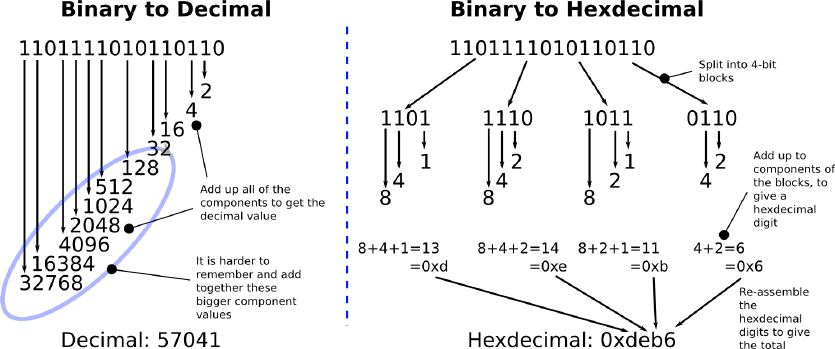
So, returning to the benefit of hexadecimal: strings of bits are rather long-winded to
write out but are much easier to convert to and from the more shorthand hexadecimal
notation than to and from our natural decimal system, essentially because we can break
the conversion down into smaller, 4-bit segments of the binary number, rather than try
to add up all of the component bits into a grand total, which gets much harder for larger
bit strings (e.g. 16, 32, 64, etc.). This difficulty with decimal conversion is shown clearly
by the example given in Figure 2.3.
Figure 2.3: Conversion of 1101111010110110 to decimal and hexadecimal

Chapter 3
Boot Sector Programming (in
16-bit Real Mode)
Even with the example code provided, you will no doubt have found it frustrating writing
machine code in a binary editor. You’d have to remember, or continuously reference,
which of many possible machine codes cause the CPU to do certain functions. Luckily,
you are not alone, and so assemblers have been written that translate more human
friendly instructions into machine code for a particular CPU.
In this chapter we will explore some increasingly sophisticated boot sector programs
to familiarise ourselves with assembly and the barren, pre-OS environment in which our
programs will run.
3.1 Boot Sector Re-visited
Now, we will re-create the binary-edited boot sector from Section XXX instead using
assembly language, so that we can really appreciate the value even of a very low-level
language.
We can assemble this into actual machine code (a sequence of bytes that our CPU
can interpret as instructions) as follows:
$nasm boot sect.asm -f bin -o boot sect.bin
Where boot sect.asm is the file into which we saved the source code in Figure 3.1
and boot sect.bin is the assembled machine code that we can install as a boot sector
on a disk.
Note that we used the -f bin option to instruct nasm to produce raw machine code,
rather than a code package that has additional meta information for linking in other rou-
tines that we would expect to use when programming in a more typical operating system
environment. We need none of that cruft. Apart from the low-level BIOS routines, we
are the only software running on this computer now. We are the operating system now,
albeit at this stage with nothing more to offer than an endless loop --- but we will soon
build up from this.
8

CHAPTER 3. BOOT SECTOR PROGRAMMING (IN 16-BIT REAL
MODE) 9
;
; A si mple boot sector pr o gram that loops for eve r.
;
loop : ; D efine a label , " loop " , that will allow
; us to jump back to it , fo reve r.
jmp loop ; Use a si mple CPU in st ruc tio n that ju mps
; to a new memory ad dres s to co nti nue ex ecu tio n.
; In our case , jump to the ad dres s of the cu rren t
; ins tr uct io n.
times 510 -($ - $$ ) db 0 ; When compiled , our progr am must fit into 512 bytes ,
; with the last two bytes being the magic number ,
; so here , tell our as semb ly co mpil er to pad out our
; p rogr am with e nough zero bytes ( db 0) to b ring us to the
; 510 th byte.
dw 0 xaa55 ; Last two bytes ( one word ) form the magic number ,
; so BIOS k nows we are a boot sect or.
Figure 3.1: A simple boot sector written in assembly language.
Rather than saving this to the boot sector of a floppy disk and rebooting our machine,
we can conveniently test this program by running Bochs:
$bochs
Or, depending on our preference and on availability of an emulator, we could use
QEmu, as follows:
$qemu boot sect.bin
Alternatively, you could load the image file into virtualisation software or write it
onto some bootable medium and boot it from a real computer. Note that, when you
write an image file to some bootable medium, that does not mean you add the file to the
medium’s file system: you must use an appropriate tool to write directly to the medium
in a low-level sense (e.g. directly to the sectors of a disk).
If we’d like to see more easily exactly what bytes the assembler created, we can run
the following command, which displays the binary contents of the file in an easy-to-read
hexadecimal format:
$od -t x1 -A n boot sect.bin
The output of this command should look familiar.
Congratulations, you just wrote a boot sector in assembly language. As we will see,
all operating systems must start this way and then pull themselves up into higher level
abstractions (e.g. higher level languages, such as C/C++)
CHAPTER 3. BOOT SECTOR PROGRAMMING (IN 16-BIT REAL
MODE) 10
3.2 16-bit Real Mode
CPU manufacturers must go to great lengths to keep their CPUs (i.e. their specific
instruction set) compatible with earlier CPUs, so that older software, and in particular
older operating systems, can still run on the most modern CPUs.
The solution implemented by Intel and compatible CPUs is to emulate the oldest
CPU in the family: the Intel 8086, which had support for 16-bit instructions and no
notion of memory protection: memory protection is crucial for the stabilty of modern
operating systems, since it allows an operating system to restrict a user’s process from
accessing, say, kernel memory, which, whether done accidentally or on purpose, could
allow such a process to circumvent security mechanisms or even bring down the whole
system.
So, for backward compatibility, it is important that CPUs boot initially in 16-bit
real mode, requiring modern operating systems explicitly to switch up into the more
advanced 32-bit (or 64-bit) protected mode, but allowing older operating systems to
carry on, blissfully unaware that they are running on a modern CPU. Later on, we will
look at this important step from 16-bit real mode into 32-bit protected mode in detail.
Generally, when we say that a CPU is 16-bit, we mean that its instructions can work
with a maximum of 16-bits at once, for example: a 16-bit CPU will have a particular
instruction that can add two 16-bit numbers together in one CPU cycle; if it was neces-
sary for a process to add together two 32-bit numbers, then it would take more cycles,
that make use of 16-bit addition.
First we will explore this 16-bit real mode environment, since all operating systems
must begin here, then later we will see how to switch into 32-bit protected mode and the
main benefits of doing so.
3.3 Erm, Hello?
Now we are going to write a seemingly simple boot sector program that prints a short
message on the screen. To do this we will have to learn some fundamentals of how the
CPU works and how we can use BIOS to help us to manipulate the screen device.
Firstly, let’s think about what we are trying to do here. We’d like to print a character
on the screen but we do not know exactly how to communicate with the screen device,
since there may be many different kinds of screen devices and they may have different
interfaces. This is why we need to use BIOS, since BIOS has already done some auto
detection of the hardware and, evidently by the fact that BIOS earlier printed information
on the screen about self-testing and so on, so can offer us a hand.
So, next, we’d like to ask BIOS to print a character for us, but how do we ask BIOS
to do that? There are no Java libraries for printing to the screen --- they are a dream
away. We can be sure, however, that somewhere in the memory of the computer there
will be some BIOS machine code that knows how to write to the screen. The truth is
that we could possibly find the BIOS code in memory and execute it somehow, but this
is more trouble than it is worth and will be prone to errors when there are differences
between BIOS routine internals on different machines.
Here we can make use of a fundamental mechanism of the computer: interrupts.
CHAPTER 3. BOOT SECTOR PROGRAMMING (IN 16-BIT REAL
MODE) 11
3.3.1 Interrupts
Interrupts are a mechanism that allow the CPU temporarily to halt what it is doing and
run some other, higher-priority instructions before returning to the original task. An
interrupt could be raised either by a software instruction (e.g. int 0x10) or by some
hardware device that requires high-priority action (e.g. to read some incoming data from
a network device).
Each interrupt is represented by a unique number that is an index to the interrupt
vector, a table initially set up by BIOS at the start of memory (i.e. at physical address
0x0) that contains address pointers to interrupt service routines (ISRs). An ISR is simply
a sequence of machine instructions, much like our boot sector code, that deals with a
specific interrupt (e.g. perhaps to read new data from a disk drive or from a network
card).
So, in a nutshell, BIOS adds some of its own ISRs to the interrupt vector that
specialise in certain aspects of the computer, for example: interrupt 0x10 causes the
screen-related ISR to be invoked; and interrupt 0x13, the disk-related I/O ISR.
However, it would be wasteful to allocate an interrupt per BIOS routine, so BIOS
multiplexes the ISRs by what we could imagine as a big switch statement, based usually
on the value set in one of the CPUs general purpose registers, ax, prior to raising the
interrupt.
3.3.2 CPU Registers
Just as we use variables in a higher level languages, it is useful if we can store data tem-
porarily during a particular routine. All x86 CPUs have four general purpose registers,
ax, bx, cx, and dx, for exactly that purpose. Also, these registers, which can each hold
a word (two bytes, 16 bits) of data, can be read and written by the CPU with negligible
delay as compared with accessing main memory. In assembly programs, one of the most
common operations is moving (or more accurately, copying) data between these registers:
mov ax , 1234 ; st ore the deci mal numb er 1234 in ax
mov cx , 0 x2 34 ; st ore the hex numbe r 0 x234 in cx
mov dx , ’ t ’ ; st ore the ASCII code for l etter ’t ’ in dx
mov bx , ax ; copy the value of ax into bx , so now bx == 1234
Notice that the destination is the first and not second argument of the mov operation,
but this convention varies with different assemblers.
Sometimes it is more convenient to work with single bytes, so these registers let us
set their high and low bytes independently:
mov ax , 0 ; ax -> 0 x0000 , or in b inary 0 00 00 000 00 00 000 0
mov ah , 0 x56 ; ax -> 0 x5600
mov al , 0 x23 ; ax -> 0 x5623
mov ah , 0 x16 ; ax -> 0 x1623
[?]
3.3.3 Putting it all Together
So, recall that we’d like BIOS to print a character on the screen for us, and that we
can invoke a specific BIOS routine by setting ax to some BIOS-defined value and then

CHAPTER 3. BOOT SECTOR PROGRAMMING (IN 16-BIT REAL
MODE) 12
triggering a specific interrupt. The specific routine we want is the BIOS scrolling tele-
type routine, which will print a single character on the screen and advance the cursor,
ready for the next character. There is a whole list of BIOS routines published that show
you which interrupt to use and how to set the registers prior to the interrupt. Here, we
need interrupt 0x10 and to set ah to 0x0e (to indicate tele-type mode) and al to the
ASCII code of the character we wish to print.
;
; A si mple boot sector that prints a me ssag e to the sc reen using a BIOS rout ine.
;
mov ah , 0 x0e ; int 10/ ah = 0 eh -> scr oll ing t elet ype BIOS rout ine
mov al , ’ H ’
int 0 x10
mov al , ’ e ’
int 0 x10
mov al , ’ l ’
int 0 x10
mov al , ’ l ’
int 0 x10
mov al , ’ o ’
int 0 x10
jmp $ ; Jump to the c urre nt addr ess ( i.e. f orev er ) .
;
; P addi ng and magic BIOS numbe r.
;
times 510 -($ - $$ ) db 0 ; Pad the boot sect or out with zero s
dw 0 xaa55 ; Last two bytes form the magic number ,
; so BIOS k nows we are a boot sect or.
Figure 3.2:
Figure 3.2 shows the whole boot sector program. Notice how, in this case, we only
needed to set ah once, then just changed al for different characters.
b4 0 e b0 48 cd 10 b0 65 cd 10 b0 6 c cd 10 b0 6c
cd 10 b0 6 f cd 10 e9 fd ff 00 00 00 00 00 00 00
00 00 00 00 00 00 00 00 00 00 00 00 00 00 00 00
*
00 00 00 00 00 00 00 00 00 00 00 00 00 00 55 aa
Figure 3.3:
CHAPTER 3. BOOT SECTOR PROGRAMMING (IN 16-BIT REAL
MODE) 13
Just for completeness, Figure 3.3 shows the raw machine code of this boot sector.
These are the actual bytes that are telling the CPU exactly what to do. If you are
surprised by the amount of effort and understanding that is involved in writing such a
barely --- if at all --- useful program, then remember that these instructions map very
closely to the CPU’s circuitry, so necessarily they are very simple, but also very fast.
You are getting to know your computer now, as it really is.
3.4 Hello, World!
Now we are going to attempt a slightly more advanced version of the ’hello’ program,
that introduces a few more CPU fundamentals and an understanding of the landscape
of memory into which our boot sector gets plonked by BIOS.
3.4.1 Memory, Addresses, and Labels
We said earlier how the CPU fetches and executes instructions from memory, and how it
was BIOS that loaded our 512-byte boot sector into memory and then, having finished
its initialisations, told the CPU to jump to the start of our code, whereupon it began
executing our first instruction, then the next, then the next, etc.
So our boot sector code is somewhere in memory; but where? We can imagine the
main memory as long sequence of bytes that can individually be accessed by an address
(i.e. an index), so if we want to find out what is in the 54th byte of memory, then 54 is
our address, which is often more convenient to express in hexadecimal: 0x36.
So the start of our boot-sector code, the very first machine code byte, is at some
address in memory, and it was BIOS that put us there. We might assume, unless we
knew otherwise, that BIOS loaded our code at the start of memory, at address 0x0. It’s
not so straightforward, though, because we know that BIOS has already being doing
initialisation work on the computer long before it loaded our code, and will actually
continue to service hardware interrupts for the clock, disk drives, and so on. So these
BIOS routines (e.g. ISRs, services for screen printing, etc.) themselves must be stored
somewhere in memory and must be preserved (i.e. not overwritten) whilst they are
still of use. Also, we noted earlier that the interrupt vector is located at the start of
memory, and were BIOS to load us there, our code would stomp over the table, and upon
the next interrupt occurring, the computer will likely crash and reboot: the mapping
between interrupt number and ISR would effectively have been severed.
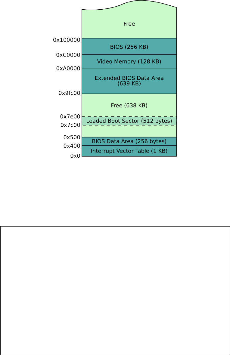
As it turns out, BIOS likes always to load the boot sector to the address 0x7c00,
where it is sure will not be occupied by important routines. Figure 3.4 gives an example
of the typical low memory layout of the computer when our boot sector has just been
loaded [?]. So whilst we may instruct the CPU to write data to any address in memory,
it may cause bad things to happen, since some memory is being used by other routines,
such as the timer interrupt and disk devices.
3.4.2 ’X’ Marks the Spot
Now we are going to play a game called “find the byte”, which will demonstrate memory
referencing, the use of labels in assembly code, and the importance of knowing where
BIOS loaded us to. We are going to write an assembly program that reserves a byte of
CHAPTER 3. BOOT SECTOR PROGRAMMING (IN 16-BIT REAL
MODE) 14
Figure 3.4: Typical lower memory layout after boot.
data for a character, then we will try to print out that character on the screen. To do
this we need to figure out its absolute memory address, so we can load it into al and get
BIOS to print it, as in the last exercise.
;
; A si mple boot sector pr o gram that de mon st rat es a ddr ess ing .
;
mov ah , 0 x0e ; int 10/ ah = 0 eh -> sc rol lin g tele type BIOS rou tine
; Fi rst atte mpt
mov al , t he_ sec ret
int 0 x10 ; Does this p rint an X?
; S econd at temp t
mov al , [ the _se cre t ]
int 0 x10 ; Does this p rint an X?
; Th ird atte mpt
mov bx , t he_ sec ret
add bx , 0 x7c00
mov al , [ bx ]
int 0 x10 ; Does this p rint an X?
; F ourth at temp t

CHAPTER 3. BOOT SECTOR PROGRAMMING (IN 16-BIT REAL
MODE) 15
mov al , [0 x7c1e ]
int 0 x10 ; Does this p rint an X?
jmp $ ; Jump fore ver .
the _se cre t :
db " X "
; P addi ng and magic BIOS numbe r.
times 510 -($ - $$ ) db 0
dw 0 xaa55
Firstly, when we declare some data in our program, we prefix it with a label (the secret).
We can put labels anywhere in our programs, with their only purpose being to give us a
convenient offset from the start of the code to a particular instruction or data.
b4 0 e b0 1 e cd 10 a0 1e 00 cd 10 bb 1e 00 81 c3
00 7 c 8a 07 cd 10 a0 1e 7 c cd 10 e9 fd ff 58 00
00 00 00 00 00 00 00 00 00 00 00 00 00 00 00 00
*
00 00 00 00 00 00 00 00 00 00 00 00 00 00 55 aa
Figure 3.5:
If we look at the assembled machine code in Figure 3.5, we can see that our ’X’,
which has an hexadecimal ASCII code 0x58, is at an offset of 30 (0x1e) bytes from the
start of the code, immediately before we padded the boot sector with zeros.
If we run the program we see that only the second two attempts succeed in printing
an ’X’.
The problem with the first attempt is that it tries to load the immediate offset into
al as the character to print, but actually we wanted to print the character at the offset
rather than the offset itself, as attempted next, whereby the square brackets instruct the
CPU to do this very thing - store the contents of an address.
So why does the second attempt fail? The problem is, that the CPU treats the offset
as though it was from the start of memory, rather than the start address of our loaded
code, which would land it around about in the interrupt vector. In the third attempt,
we add the offset the secret to the address that we beleive BIOS to have loaded our
code, 0x7c00, using the CPU add instruction. We can think of add as the higher level
language statement bx = bx + 0x7c00. We have now calculated the correct memory
address of our ’X’ and can store the contents of that address in al, ready for the BIOS
print function, with the instruction mov al, [bx].
In the fourth attempt we try to be a bit clever, by pre-calculating the address of the
’X’ after the boot sector is loaded into memory by BIOS. We arrive at the address 0x7c1e
based on our earlier examination of the binary code (See Figure 3.5) which revealed that
’X’ was 0x1e (30) bytes from the start of our boot sector. This last example reminds

CHAPTER 3. BOOT SECTOR PROGRAMMING (IN 16-BIT REAL
MODE) 16
us why labels are useful, since without labels we would have to count offsets from the
compiled code, and then update these when changes in code cause these offsets to change.
So now we have seen how BIOS does indeed load our boot sector to the address
0x7c00, and we have also seen how addressing and assembly code labels are related.
It is inconvenient to always have to account for this label--memory offset in your
code, so many assemblers will correct label references during assemblege if you include
the following instruction at the top of your code, telling it exactly where you expect the
code to loaded in memory:
[ org 0 x7c00 ]
Question 1
What do you expect will be printed now, when this org directive is added to this boot-
sector program? For good marks, explain why this is so.
3.4.3 Defining Strings
Supposing you wanted to print a pre-defined message (e.g. “Booting OS”) to the screen
at some point; how would you define such a string in your assembly program? We have
to remind ourselves that our computer knows nothing about strings, and that a string
is merely a sequence of data units (e.g. bytes, words, etc.) held somewhere in memory.
In the assembler we can define a string as follows:
my_ str ing :
db ’ Bo otin g OS ’
We’ve actually already seen db, which translates to “declare byte(s) of data”, which tells
the assembler to write the subsequent bytes directly to the binary output file (i.e. do not
interpret them as processor instructions). Since we surrounded our data with quotes,
the assembler knows to convert each character to its ASCII byte code. Note that, we
often use a label (e.g. my string) to mark the start of our data, otherwise we would
have no easy way of referencing it within our code.
One thing we have overlooked in this example is that knowing how long a string
is equally important as to knowing where it is. Since it is us that has to write all the
code that handles strings, it is important to have a consistent strategy for knowing how
long a string is. There are a few possibilities, but the convention is to declare strings
as null-terminating, which means we always declare the last byte of the string as 0, as
follows:
my_ str ing :
db ’ Bo otin g OS ’ ,0
When later iterating through a string, perhaps to print each of its characters in turn, we
can easily determine when we have reached the end.
CHAPTER 3. BOOT SECTOR PROGRAMMING (IN 16-BIT REAL
MODE) 17
3.4.4 Using the Stack
When on the topic of low-level computing, we often hear people talking about the stack
like it is some special thing. The stack is really just a simple solution to the following
inconvenience: the CPU has a limited number of registers for the temporary storage of
our routine’s local variables, but we often need more temporary storage than will fit into
these registers; now, we can obviously make use of main memory, but specifying specific
memory addresses when reading and writing is inconvenient, especially since we do not
care exactly where the data is to be stored, only that we can retrieve it easily enough.
And, as we shall see later, the stack is also useful for argument passing to realise function
calls.
So, the CPU offers two instructions push and pop that allow us, respectively, to store
a value and retrieve a value from the top of the stack, and so without worrying exactly
where they are stored. Note, however, that we cannot push and pop single bytes onto
and off the stack: in 16-bit mode, the stack works only on 16-bit boundaries.
The stack is implemented by two special CPU registers, bp and sp, which maintain
the addresses of the stack base (i.e. the stack bottom) and the stack top respectively.
Since the stack expands as we push data onto it, we usually set the stack’s base far away
from important regions of memory (e.g. such as BIOS code or our code) so their is no
danger of overwriting if the stack grows too large. One confusing thing about the stack
is that it actually grows downwards from the base pointer, so when we issue a push,
the value actually gets stored below --- and not above --- the address of bp, and sp is
decremented by the value’s size.
The following boot sector program in Figure 3.6 demonstrates use of the stack.
Question 2
What will be printed in what order by the code in Figure 3.6? And at what absolute
memory address will the ASCII character ’C’ be stored? You may find it useful to modify
the code to confirm your expectation, but be sure to explain why it is this address.
3.4.5 Control Structures
We’d never be comfortable using a programming language if we didn’t know how to
write some basic control structures, such as if..then..elseif..else, for, and while.
These structures allow alternative branches of execution and form the basis of any useful
routine.
After compilation, these high-level control structures reduce to simple jump state-
ments. Actually, we’ve already seen the simplest example of loops:
som e_l abe l :
jmp s ome _la bel ; jump to a ddre ss of lab el
Or alternatively, with identical effect:
jmp $ ; jump to a ddre ss of c urre nt in str uct io n
So this instruction offers us an unconditional jump (i.e. it will always jump); but we
often need to jump based on some condition (e.g. carry on looping until we have looped
ten times, etc.).

CHAPTER 3. BOOT SECTOR PROGRAMMING (IN 16-BIT REAL
MODE) 18
;
; A si mple boot sector pr o gram that de mon st rat es the sta ck.
;
mov ah , 0 x0e ; int 10/ ah = 0 eh -> scr oll ing t elet ype BIOS rout ine
mov bp , 0 x8000 ; Set the base of the stack a littl e above where BIOS
mov sp , bp ; loads our boot sector - so it won ’t ove rwr ite us.
push ’A ’ ; Push some c har act ers on the stack for later
push ’B ’ ; r etr eiv al. Note , thes e are p ushed on as
push ’C ’ ; 16 - bit values , so the most s ig nif ica nt byte
; will be added by our a sse mbl er as 0 x00.
pop bx ; Note , we can only pop 16 - bits , so pop to bx
mov al , bl ; the n copy bl ( i.e. 8 - bit char ) to al
int 0 x10 ; pr int ( al )
pop bx ; Pop the next value
mov al , bl
int 0 x10 ; pr int ( al )
mov al , [0 x7ffe ] ; To prove our stack grows d ownw ard s from bp ,
; fe tch the char at 0 x8000 - 0 x2 ( i.e. 16- bits )
int 0 x10 ; pr int ( al )
jmp $ ; Jump fo reve r.
; P addi ng and magic BIOS numbe r.
times 510 -($ - $$ ) db 0
dw 0 xaa55
Figure 3.6: Manipulation of the stack, using push and pop
Conditional jumps are achieved in assembly language by first running a comparison
instruction, then by issuing a specific conditional jump instruction.
cmp ax , 4 ; co mpar e the v alue in ax to 4
je the n_ blo ck ; j ump to th en_ blo ck if t hey were equal
mov bx , 45 ; oth erwise , exe cute this code
jmp th e_en d ; i mpo rta nt : jump over the ’ then ’ block ,
; so we don ’t also exec ute that code.
the n_b loc k :
mov bx , 23
the_ end :
In a language such as C or Java, this would look like this:
if( ax == 4) {
bx = 23;
} else {
bx = 45;
}
CHAPTER 3. BOOT SECTOR PROGRAMMING (IN 16-BIT REAL
MODE) 19
We can see from the assembly example that there is something going on behind the
scenes that is relating the cmp instruction to the je instruction it proceeds. This is an
example of where the CPU’s special flags register is used to capture the outcome of
the cmp instruction, so that a subsequent conditional jump instruction can determine
whether or not to jump to the specified address.
The following jump instructions are available, based on an earlier cmp x, y instruc-
tion:
je targe t ; jump if eq ual ( i.e. x == y )
jne tar get ; ju mp if not equal ( i.e. x != y)
jl targe t ; jump if less than (i .e. x < y)
jle tar get ; ju mp if less than or equal ( i.e. x <= y )
jg targe t ; jump if g reat er than ( i.e. x > y )
jge tar get ; ju mp if gre ater than or equa l ( i.e. x >= y )
Question 3
It’s always useful to plan your conditional code in terms of a higher level language, then
replace it with the assembly instructions. Have a go at converting this pseudo assembly
code into full assembly code, using cmp and appropriate jump instructions. Test it with
different values of bx. Fully comment your code, in your own words.
mov bx , 30
if ( bx <= 4) {
mov al , ’ A ’
} else if ( bx < 40) {
mov al , ’ B ’
} else {
mov al , ’ C ’
}
mov ah , 0 x0e ; int =10/ ah =0 x0e -> BIOS tele - type outpu t
int 0 x10 ; pri nt the char act er in al
jmp $
; P addi ng and magic num ber.
times 510 -($ - $$ ) db 0
dw 0 xaa55
3.4.6 Calling Functions
In high-level languages, we break big problems down into functions, which essentially
are general purpose routines (e.g. print a message, write to a file, etc.) that we use
over and over again throughout our program, usually changing parameters that we pass
to the function to change the outcome in some way. At the CPU level a function is
nothing more than a jump to the address of a useful routine then a jump back again to
the instruction immediately following the first jump.
We can kind of simulate a function call like this:
...
...
mov al , ’ H ’ ; St ore ’H ’ in al so our fu nct ion will p rint it.

CHAPTER 3. BOOT SECTOR PROGRAMMING (IN 16-BIT REAL
MODE) 20
jmp m y_ pri nt _f un ct ion
ret ur n_ to_ he re : ; T his la bel is our life - line so we can get bac k.
...
...
my _pr in t_ fu nct io n :
mov ah , 0 x0e ; int =10/ ah =0 x0e -> BIOS tele - type output
int 0 x10 ; pr int the cha rac t er in al
jmp r etu rn _t o_h er e ; retur n from the fu nct ion call.
Firstly, note how we used the register al as a parameter, by setting it up ready for
the function to use. This is how parameter passing is made possible in higher level
languages, where the caller and callee must have some agreement on where and how
many parameters will be passed.
Sadly, the main flaw with this approach is that we need to say explicitly where to
return to after our function has been called, and so it will not be possible to call this
function from arbitrary points in our program --- it will always return the same address,
in this case the label return to here.
Borrowing from the parameter passing idea, the caller code could store the correct
return address (i.e. the address immediately after the call) in some well-known location,
then the called code could jump back to that stored address. The CPU keeps track of the
current instruction being executed in the special register ip (instruction pointer), which,
sadly, we cannot access directly. However, the CPU provides a pair of instructions, call
and ret, which do exactly what we want: call behaves like jmp but additionally, before
actually jumping, pushes the return address on to the stack; ret then pops the return
address off the stack and jumps to it, as follows:
...
...
mov al , ’ H ’ ; St ore ’H ’ in al so our fu nct ion will p rint it.
call my_ pr in t_ fun ct io n
...
...
my _pr in t_ fu nct io n :
mov ah , 0 x0e ; int =10/ ah =0 x0e -> BIOS tele - type output
int 0 x10 ; pr int the cha rac t er in al
ret
Our functions are almost self-contained now, but there is a still an ugly problem that we
will thank ourselves later for if we now take the trouble to consider it. When we call a
function, such as a print function, within our assembly program, internally that function
may alter the values of several registers to perform its job (indeed, with registers being
a scarce resource, it will almost certainly do this), so when our program returns from
the function call it may not be safe to assume, say, the value we stored in dx will still be
there.
It is often sensible (and polite), therefore, for a function immediately to push any
registers it plans to alter onto the stack and then pop them off again (i.e. restore the
registers’ original values) immediately before it returns. Since a function may use many
of the general purpose registers, the CPU implements two convenient instructions, pusha
and popa, that conveniently push and pop all registers to and from the stack respectively,
for example:
...

CHAPTER 3. BOOT SECTOR PROGRAMMING (IN 16-BIT REAL
MODE) 21
...
som e_ fun ct ion :
pusha ; Push all re gist er valu es to the sta ck
mov bx , 10
add bx , 20
mov ah , 0 x0e ; int =10/ ah =0 x0e -> BIOS tele - type output
int 0 x10 ; pr int the cha rac t er in al
popa ; Rest ore or igin al reg ist er value s
ret
3.4.7 Include Files
After slaving away even on the seemingly simplest of assembly routines, you will likely
want to reuse your code in multiple programs. nasm allows you to include external files
literally as follows:
% i nclu de " my_ pr in t_ fu nc ti on .a sm " ; this will simply get re pla ced by
; the cont ents of the file
...
mov al , ’ H ’ ; St ore ’H ’ in al so our fu nct ion will p rint it.
call my_ pr in t_ fun ct io n
3.4.8 Putting it all Together
We now have enough knowledge about the CPU and assembly to write a more sophisti-
cated “Hello, World” boot sector program.
Question 4
Put together all of the ideas in this section to make a self-contained function for printing
null-terminated strings, that can be used as follows:
;
; A boot secto r that pri nts a strin g using our fun cti on.
;
[ org 0 x7c00 ] ; Tell the ass emb ler wher e this code will be loaded
mov bx , H ELL O_MS G ; Use BX as a p ara mete r to our function , so
call pri nt_ st rin g ; we can sp ecif y the addre ss of a st ring .
mov bx , G OOD BYE _M SG
call pri nt_ st rin g
jmp $ ; Hang
% i nclu de " pri nt _s tri ng .a sm "
; Data
HEL LO_ MSG :
db ’ Hello , Wo rld ! ’, 0 ; <-- The zero on the end tells our rout ine

CHAPTER 3. BOOT SECTOR PROGRAMMING (IN 16-BIT REAL
MODE) 22
; when to stop pr int ing ch ar act ers .
GOO DBY E_ MSG :
db ’ Go odby e ! ’ , 0
; P addi ng and magic num ber.
times 510 -($ - $$ ) db 0
dw 0 xaa55
For good marks, make sure the function is careful when modifying registers and that
you fully comment the code to demonstrate your understanding.
3.4.9 Summary
Still, it feels that we have not come very far. That’s okay, and that’s quite normal, given
the primitive environment that we have been working in. If you have understood all up
until here, then we are well on our way.
3.5 Nurse, Fetch me my Steth-o-scope
So far we have managed to get the computer to print out characters and strings that we
have loaded into memory, but soon we will be trying to load some data from the disk,
so it will be very helpful if we can display the hexadecimal values stored at aribitrary
memory addresses, to confirm if we have indeed managed to load anything. Remember,
we do not have the luxury of a nice development GUI, complete with a debugger that will
let us carefully step though and inspect our code, and the best feedback the computer
can give us when we make a mistake is visibly to do nothing at all, so we need to look
after ourselves.
We have already written a routine to print out a string of characters, so we will
now extend that idea into a hexadecimal printing routine --- a routine certainly to be
cherished in this unforgiving, low-level world.
Let’s think carefully about how we will do this, starting by considering how we’d like
to use the routine. In a high-level language, we’d like something like this: print hex(0x1fb6),
which would result in the string ’0x1fb6’ being printed on the screen. We have already
seen, in Section XXX, how functions can be called in assembly and how we can use
registers as parameters, so let’s use the dx register as a parameter to hold the value we
wish our print hex function to print:
mov dx , 0 x1fb6 ; s tore the value to pri nt in dx
call prin t_h ex ; call the func tion
; p rints the valu e of DX as hex .
pri nt_ hex :
...
...
ret

CHAPTER 3. BOOT SECTOR PROGRAMMING (IN 16-BIT REAL
MODE) 23
Since we are printing a string to the screen, we might as well re-use our earlier printing
function to do the actual printing part, then our main task is to look at how we can build
that string from the value in our parameter, dx. We definitely don’t want to confuse
matters more than we need to when working in assembly, so let’s consider the following
trick to get us started with this function. If we define the complete hexadecimal string as
a sort of template variable in our code, as we defined our earlier “Hello, World” messages,
we can simply get the string printing function to print it, then the task of our print hex
routine is to alter the components of that template string to reflect the hexadecimal
value as ASCII codes:
mov dx , 0 x1fb6 ; s tore the value to pri nt in dx
call prin t_h ex ; call the func tion
; p rints the valu e of DX as hex .
pri nt_ hex :
; TODO : man ipu lat e chars at H EX_O UT to r efle ct DX
mov bx , HE X_OU T ; pri nt the string po inte d to
call pri nt_ st rin g ; by BX
ret
; g lobal v aria ble s
HEX_ OUT : db ’0 x0000 ’ ,0
3.5.1 Question 5 (Advanced)
Complete the implementation of the print hex function. You may find the CPU instruc-
tions and and shr to be useful, which you can find information about on the Internet.
Make sure to fully explain your code with comments, in your own words.
3.6 Reading the Disk
We have now been introduced to BIOS, and have had a little play in the computer’s
low-level environment, but we have a little problem that poses to get in the way of our
plan to write an operating system: BIOS loaded our boot code from the first sector of
the disk, but that is all it loaded; what if our operating system code is larger --- and I’m
guessing it will be --- than 512 bytes.
Operating systems usually don’t fit into a single (512 byte) sector, so one of the first
things they must do is bootstrap the rest of their code from the disk into memory and
then begin executing that code. Luckily, as was hinted at earlier, BIOS provides routines
that allow us to manipulate data on the drives.
3.6.1 Extended Memory Access Using Segments
When the CPU runs in its intial 16-bit real mode, the maximum size of the registers is 16
bits, which means that the highest address we can reference in an instruction is 0xffff,
which amounts by today’s standards to a measily 64 KB (65536 bytes). Now, perhaps
the likes of our intended simple operating system would not be affected by this limit,

CHAPTER 3. BOOT SECTOR PROGRAMMING (IN 16-BIT REAL
MODE) 24
but a day-to-day operating systems would never sit comfortably in such a tight box, so
it is important that we understand the solution, of segmentation, to this problem.
To get around this limitation, the CPU designers added a few more special registers,
cs, ds, ss, and es, called segment registers. We can imagine main memory as being
divided into segments that are indexed by the segment registers, such that, when we
specify a 16-bit address, the CPU automatically calculates the absolute address as the
appropriate segment’s start address offseted by our specified address [?]. By appropriate
segment, I mean that, unless explicitly told otherwise, the CPU will offset our address
from the segment register appropriate for the context of our instruction, for example:
the address used in the instruction mov ax, [0x45ef] would by default be offset from
the data segment, indexed by ds; similarly, the stack segment, ss, is used to modify the
actual location of the stack’s base pointer, bp.
The most confusing thing about segment addressing is that adjacent segments overlap
almost completely but for 16 bytes, so different segment and offset combinations can
actually point to the same physical address; but enough of the talk: we won’t truly
grasp this concept until we’ve seen some examples.
To calculate the absolute address the CPU multiplies the value in the segment register
by 16 and then adds your offset address; and because we are working with hexadecimal,
when we multiple a number by 16, we simply shift it a digit to the left (e.g. 0x42 * 16
= 0x420). So if we set ds to 0x4d and then issue the statement mov ax, [0x20], the
value stored in ax will actually be loaded from address 0x4d0 (16 * 0x4d + 0x20).
Figure 3.7 shows how we can set ds to achieve a similar correction of label addressing
as when we used the [org 0x7c00] directive in Section XXX. Because we do not use the
org directive, the assmebler does not offset our labels to the correct memory locations
when the code is loaded by BIOS to the address 0x7c00, so the first attempt to print an
’X’ will fail. However, if we set the data segment register to 0x7c0, the CPU will do this
offset for us (i.e. 0x7c0 * 16 + the secret), and so the second attempt will correctly
print the ’X’. In the third and fourth attempts we do the same, and get the same results,
but instead explicitly state to the CPU which segment register to use when computing
the physical address, using instead the general purpose segment register es.
Note that limitations of the CPU’s circuitry (at least in 16-bit real mode) reveal
themselves here, when seemingly correct instructions like mov ds, 0x1234 are not actu-
ally possibly: just because we can store a literal address directly into a general purpose
register (e.g. mov ax, 0x1234 or mov cx, 0xdf), it doesn’t mean we can do the same
with every type of register, such as segment registers; and so, as in Figure 3.7, we must
take an additional step to transfer the value via a general purpose register.
So, segment-based addressing allows us to reach further into memory, up to a little
over 1 MB (0xffff * 16 + 0xffff). Later, we will see how more memory can be accessed,
when we switch to 32-bit protected mode, but for now it suffices for us to understand
16-bit real mode segment-based addressing.
3.6.2 How Disk Drives Work
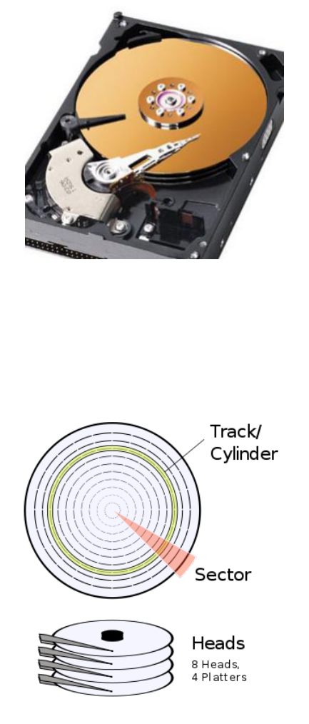
Mechanically, hard disk drives contain one or more stacked platters that spin under a
read/write head, much like an old record player, only potentially, to increase capacity,
with several records stacked one above the other, where a head moves in and out to get
coverage of the whole of a particular spinning platter’s surface; and since a particular
platter may be readible and writable on both of its surfaces, one read/write head may

CHAPTER 3. BOOT SECTOR PROGRAMMING (IN 16-BIT REAL
MODE) 25
;
; A si mple boot sector pr o gram that de mon st rat es se gmen t offs et tin g
;
mov ah , 0 x0e ; int 10/ ah = 0 eh -> sc rol lin g tele type BIOS rou tine
mov al , [ the _se cre t ]
int 0 x10 ; D oes this print an X?
mov bx , 0 x7 c0 ; Can ’t set ds d irectly , so set bx
mov ds , bx ; then copy bx to ds.
mov al , [ the _se cre t ]
int 0 x10 ; D oes this print an X?
mov al , [ es : the_ sec re t ] ; Tell the CPU to use the es ( not ds ) s egm ent.
int 0 x10 ; D oes this print an X?
mov bx , 0 x7 c0
mov es , bx
mov al , [ es : the_ sec re t ]
int 0 x10 ; D oes this print an X?
jmp $ ; Jump fo reve r.
the _se cre t :
db " X "
; P addi ng and magic BIOS numbe r.
times 510 -($ - $$ ) db 0
dw 0 xaa55
Figure 3.7: Manipulating the data segment with the ds register.
float above and another below it. Figure 3.8 shows the inside of a typical hard disk
drive, with the stack of platters and heads exposed. Note that the same idea applies to
floppy disk drives, which, instead of several stacked hard platters, usually have a single,
two-sided floppy disk medium.
The metalic coating of the platters give them the property that specific areas of their
surface can be magnetised or demagnetised by the head, effectively allowing any state
to be recorded permanently on them [?]. It is therefore important to be able to describe
the exact place on the disk’s surface where some state is to be read or written, and
so Cylinder-Head-Sector (CHS) addressing is used, which effectively is a 3D coordinate
system (see Figure 3.9):
• Cylinder: the cylinder describes the head’s discrete distance from the outer edge
of the platter and is so named since, when several platters are stacked up, you
can visualise that all of the heads select a cylinder through all of the platters
• Head: the head describes which track (i.e. which specific platter surface within
the cylinder) we are interested in.
• Sector: the circular track is divided into sectors, usually of capacity 512 bytes,
which can be referenced with a sector index.
CHAPTER 3. BOOT SECTOR PROGRAMMING (IN 16-BIT REAL
MODE) 26
Figure 3.8: Inside of a hard disk drive
Figure 3.9: Cylinder, Head, Sector structure of a hard disk.
CHAPTER 3. BOOT SECTOR PROGRAMMING (IN 16-BIT REAL
MODE) 27
3.6.3 Using BIOS to Read the Disk
As we will see a little later on, specific devices require specific routines to be written
to use them, so, for example, a floppy disk device requires us to explicitly turn on and
off the motor that spins the disk under the read-and-write head before we can use it,
whereas most hard disk devices have more functionality automated on local chips [?], but
again the bus technologies with which such devices connect to the CPU (e.g. ATA/IDE,
SATA, SCSI, USB, etc.) affect how we access them. Thankfully, BIOS can offer a few
disk routines that abstract all of these differences for common disk devices.
The specific BIOS routine we are interested in here is accessed by raising interrupt
0x13 after setting the register al to 0x02. This BIOS routine expects us to set up a few
other registers with details of which disk device to use, which blocks we wish to read
from the disk, and where to store the blocks in memory. The most difficult part of using
this routine is that we must specify the first block to be read using a CHS addressing
scheme; otherwise, it is just a case of filling in the expected registers, as detailed in the
next code snippet.
mov ah , 0 x02 ; BIOS read sector fu nct ion
mov dl , 0 ; Read drive 0 ( i.e. first flo ppy drive )
mov ch , 3 ; S elect cy lin der 3
mov dh , 1 ; S elect the trac k on 2 nd side of flo ppy
; disk , sinc e this count has a bas e of 0
mov cl , 4 ; S elect the 4 th se ctor on the t rack - not
; the 5 th , sinc e this has a ba se of 1 .
mov al , 5 ; Read 5 sec tors from the start point
; Lastly , set the ad dres s th at we ’d like BI OS to r ead the
; s ecto rs to , whic h BIOS exp ects to find in ES : BX
; ( i.e. s egme nt ES with offs et BX ) .
mov bx , 0 xa000 ; Ind ire ctl y set ES to 0 x a 000
mov es , bx
mov bx , 0 x1234 ; Set BX to 0 x1234
; In our case , data wi ll be re ad to 0 xa0 00 :0 x1234 , which the
; CPU will tr ans lat e to ph ysi cal ad dres s 0 xa12 34
int 0 x13 ; Now is sue the BIOS i nte rru pt to do the actua l re ad.
Note that, for one reason or another (e.g. we indexed a sector beyond the limit of the
disk, an attempt was made to read a faulty sector, the floppy disk was not inserted into
the drive, etc.), BIOS may fail to read the disk for us, so it is important to know how
to detect this; otherwise, we may think we have read some data but in fact the target
address simply contains the same random bytes it did before we issued the read command.
Fortunately for us, BIOS updates some registers to let us know what happened: the carry
flag (CF) of the special flags register is set to signal a general fault, and al is set to the
number of sectors actually read, as opposed to the number requested. After issuing the
interrupt for the BIOS disk read, we can perform a simple check as follows:
...
...
int 0 x13 ; Is sue the BIOS i nte rru p t to do the actual read .
jc dis k_ err or ; jc is anot her jum ping ins tructi on , that j umps
; only if the carry flag was set.
; This jumps if what BIOS rep orte d as the nu mber of secto rs

CHAPTER 3. BOOT SECTOR PROGRAMMING (IN 16-BIT REAL
MODE) 28
; actu all y re ad in AL is not e qual to the n u mber we exp ect ed.
cmp al , < no. secto rs expected >
jne d isk _er ror
dis k_e rro r :
mov bx , D IS K_E RR OR_ MS G
call pri nt_ st rin g
jmp $
; G lobal v aria ble s
DIS K_ ER ROR _M SG : db " Disk read error !" , 0
3.6.4 Putting it all Together
As explained earlier, being able to read more data from the disk will be essential for boot-
strapping our operating system, so here we will put all of the ideas from this section into
a helpful routine that will simply read the first n sectors following the boot sector from
a specified disk device.
; load DH secto rs to ES : BX from drive DL
dis k_l oad :
push dx ; Store DX on stack so later we can r ecall
; how many sec tors were requ est to be read ,
; even if it is a lter ed in the meant ime
mov ah , 0 x02 ; BIOS read s ector f unct ion
mov al , dh ; Read DH secto rs
mov ch , 0 x00 ; S elect cy lin der 0
mov dh , 0 x00 ; S elect head 0
mov cl , 0 x02 ; St art readi ng from s econd sec tor ( i.e.
; af ter the boot se ctor )
int 0 x13 ; BIOS int err upt
jc dis k_ err or ; Jump if error ( i.e. car ry flag set )
pop dx ; R esto re DX from the stack
cmp dh , al ; if AL ( sect ors read ) != DH ( secto rs expe cte d )
jne d isk _er ror ; di spla y error mess age
ret
dis k_e rro r :
mov bx , D IS K_E RR OR_ MS G
call pri nt_ st rin g
jmp $
; Var iab les
DIS K_ ER ROR _M SG db " Disk read error !" , 0
And to test this routine, we can write a boot sector program as follows:

CHAPTER 3. BOOT SECTOR PROGRAMMING (IN 16-BIT REAL
MODE) 29
; Read some secto rs from the boot disk u sing our dis k_r ead fu nct ion
[ org 0 x7c00 ]
mov [ BOO T_D RIV E ] , dl ; BIOS stores our boot drive in DL , so it ’s
; best to reme mbe r this for lat er.
mov bp , 0 x8000 ; Here we set our sta ck s afely out of the
mov sp , bp ; way , at 0 x8000
mov bx , 0 x9000 ; Load 5 s ecto rs to 0 x0000 ( ES ):0 x9000 ( BX )
mov dh , 5 ; from the boot disk.
mov dl , [ BOO T_D RIV E ]
call disk _lo ad
mov dx , [0 x9000 ] ; Pr int out the first loade d word , whi ch
call prin t_h ex ; we expec t to be 0 xdada , stor ed
; at add ress 0 x9000
mov dx , [0 x9000 + 512] ; Also , pri nt the first wo rd from the
call prin t_h ex ; 2 nd load ed secto r : sho uld be 0 xface
jmp $
% i nclu de " .. / pri nt / pr in t_ str in g. as m " ; Re - use our pr in t_s tr ing f unct ion
% i nclu de " .. / hex / pr i nt _h ex. as m " ; Re - use our pri nt_ hex fu nct ion
% i nclu de " dis k_l oa d.a sm "
; I nclu de our new di sk_ loa d func tio n
; G lobal v aria ble s
BOO T_D RIV E : db 0
; Boo tse cto r padd ing
times 510 -($ - $$ ) db 0
dw 0 xaa55
; We know that BIOS will load only the fir st 512 - byte sector from the disk ,
; so if we pur pos ely add a few more sect ors to our code by rep eat ing some
; fami lia r numbers , we can pr ove to ou rse lfs that we ac tua lly loa ded those
; add iti ona l two sec tors from the disk we boote d from.
times 256 dw 0 xdada
times 256 dw 0 xface

Chapter 4
Entering 32-bit Protected Mode
It would be nice to continue working in the 16-bit real mode with which we have now
become much better aquainted, but in order to make fuller use of the CPU, and to
better understand how developments of CPU architecures can benefit modern operating
systems, namely memory protection in hardware, then we must press on into 32-bit
protected mode.
The main differences in 32-bit protected mode are:
• Registers are extended to 32 bits, with their full capacity being accessed by pre-
fixing an e to the register name, for example: mov ebx, 0x274fe8fe
• For convenience, there are two additional general purpose segment registers, fs
and gs.
• 32-bit memory offsets are available, so an offset can reference a whopping 4 GB
of memory (0xffffffff).
• The CPU supports a more sophisticated --- though slightly more complex ---
means of memory segmentation, which offers two big advantages:
– Code in one segment can be prohibited from executing code in a more priv-
ilidged segment, so you can protect your kernel code from user applications
– The CPU can implement virtual memory for user processes, such that pages
(i.e. fixed-sized chunks) of a process’s memory can be swapped transparently
between the disk and memory on an as-needed basis. This ensure main
memory is used efficiently, in that code or data that is rarely executed
needn’t hog valuable memory.
• Interrupt handling is also more sophisticated.
[?]
The most difficult part about switching the CPU from 16-bit real mode into 32-bit
protected mode is that we must prepare a complex data structure in memory called the
global descriptor table (GDT), which defines memory segments and their protected-mode
attributes. Once we have defined the GDT, we can use a special instruction to load it
30

CHAPTER 4. ENTERING 32-BIT PROTECTED MODE 31
into the CPU, before setting a single bit in a special CPU control register to make the
actual switch.
This process would be easy enough if we didn’t have to define the GDT in assembly
language, but sadly this low-level switch-over is unavoidable if we later wish to load a
kernel that has been compiled from a higher-level language such as C, which usually will
be compiled to 32-bit instructions rather than the less-efficient 16-bit instructions.
Oh, there is one shocker that I nearly forgot to mention: we can no longer use
BIOS once switched into 32-bit protected mode. If you thought making BIOS calls was
low-level. This is like one step backwards, two steps forwards.
4.1 Adapting to Life Without BIOS
It is true: in our quest to make full use of the CPU, we must abandon all of those helpful
routines provided by BIOS. As we will see when we look in more detail at the 32-bit
protected mode switch-over, BIOS routines, having been coded to work only in 16-bit
real mode, are no longer valid in 32-bit protected mode; indeed, attempting to use them
would likely crash the machine.
So what this means is that a 32-bit operating system must provide its own drivers for
all hardware of the machine (e.g. the keybaord, screen, disk drives, mouse, etc). Actually,
it is possible for a 32-bit protected mode operating system to switch temporarily back
into 16-bit mode whereupon it may utilise BIOS, but this teachnique can be more trouble
than it is worth, especially in terms of performance.
The first problem we will encounted in switching to protected mode is knowing how
to print a message on the screen, so we can see what is happening. Previously we
have asked BIOS to print an ASCII character on the screen, but how did that result in
the appropriate pixels being highlighted at the appropriate position of our computer’s
screen? For now, it suffices to know that the display device can be configured into one
of several resolutions in one of two modes, text mode and graphics mode; and that what
is displayed on the screen is a visual representation of a specific range of memory. So,
in order to manipulate the screen, we must manipulate the specific memory range that
it is using in its current mode. The display device is an example of memory-mapped
hardware because it works in this way.
When most computers boot, despite that they may infact have more advanced graph-
ics hardware, they begin in a simple Video Graphics Array (VGA) colour text mode with
dimmensions 80x25 characters. In text mode, the programmer does not need to render
individual pixels to describe specific characters, since a simple font is already defined
in the internal memory of the VGA display device. Instead, each character cell of the
screen is represented by two bytes in memory: the first byte is the ASCII code of the
character to be displayed, and the second byte encodes the characters attributes, such
as the foreground and background colour and if the character should be blinking.
So, if we’d like to display a character on the screen, then we need to set its ASCII
code and attributes at the correct memory address for the current VGA mode, which
is usually at address 0xb8000. If we slightly modify our original (16-bit real mode)
print string routine so that it no longer uses the BIOS routine, we can create a 32-bit
protected mode routine that writes directly to video memory, as in Figure 4.1.
Note that, although the screen is displayed as columns and rows, the video memory
is simply sequential. For example, the address of the column 5 on row 3 can be calculated
as follows: 0xb8000 + 2 * (row * 80 + col)

CHAPTER 4. ENTERING 32-BIT PROTECTED MODE 32
[ bits 32]
; D efine some con sta nts
VID EO _ME MOR Y equ 0 x b8000
WHI TE _O N_B LA CK equ 0 x0f
; p rints a null - te rmi nat ed stri ng point ed to by EDX
pri nt _s tri ng _p m :
pusha
mov edx , V IDE O_M EM ORY ; Set edx to the start of vid mem.
pr in t_s tr in g_ pm _l oo p :
mov al , [ ebx ] ; Sto re the cha r at EBX in AL
mov ah , W HI TE_ ON _BL AC K ; Store the at tri but es in AH
cmp al , 0 ; if ( al == 0) , at end of string , so
je done ; jump to do ne
mov [ edx ] , ax ; Store char and att rib ute s at c urre nt
; cha rac ter cell.
add ebx , 1 ; Inc rem ent EBX to the next char in st ring .
add edx , 2 ; Move to ne xt c har act er cell in vid mem.
jmp p ri nt _s tr ing _p m_ lo op ; loop aroun d to print the next char.
pr in t_s tr in g_ pm _d on e :
popa
ret ; Retu rn f rom the f unc tion
Figure 4.1: A routine for printing a string directly to video memory (i.e.
without using BIOS).
The downside to our routine is that it always prints the string to the top-left of the
screen, and so will overwrite previous messages rather than scrolling. We could spend
time adding to the sophistication of this assembly routine, but let’s not make things too
hard for ourselves, since after we master the switch to protected mode, we will soon be
booting code written in a higher level language, where we can make much lighter work
of these things.
4.2 Understanding the Global Descriptor
Table
It is important to understand the main point of this GDT, that is so fundamental to
the operation of protected mode, before we delve into the details. Recall from Section
XXX that the design rationale of segment-based addressing in the classical 16-bit real
mode was to allow the programmer to access (albeit slightly, by today’s standards) more
memory than a 16-bit offset would allow. As an example of this, suppose that the
programmer wanted to store the value of ax at the address 0x4fe56. Without segment-
CHAPTER 4. ENTERING 32-BIT PROTECTED MODE 33
based addressing, the best the programmer could do is this:
mov [0 xffff ], ax
which falls way short of the intended address. Whereby, using a segment register, the
task could be achieved as follows:
mov bx , 0 x4000
mov es , bx
mov [ es :0 xfe56 ], ax
Although the general idea of segmenting memory and using offsets to reach into those
segments has remained the same, the way that it is implented in protected mode has
completely changed, primarily to afford more flexibility. Once the CPU has been switched
into 32-bit protected mode, the process by which it translates logical addresses (i.e.
the combination of a segment register and an offset) to physical address is completely
different: rather than multiply the value of a segment register by 16 and then add to it
the offset, a segment register becomes an index to a particular segment descriptor (SD)
in the GDT.
A segment descriptor is an 8-byte structure that defines the following properties of
a protected-mode segment:
• Base address (32 bits), which defines where the segment begins in physical memory
• Segment Limit (20 bits), which defines the size of the segment
• Various flags, which affect how the CPU interprets the segment, such as the
privilige level of code that runs within it or whether it is read- or write-only.
Figure 4.2 shows the actual structure of the segment descriptor. Notice how, just
to add to the confusion, the structure fragments the base address and segment limit
throughout the structure, so, for example, the lower 16 bits of the segment limit are in
the first two bytes of the structure but the higher 4-bits are at the start of the seventh
byte of the structure. Perhaps this was done as some kind of joke, or more likley it has
historic roots or was influenced by the CPU’s hardware design.
We will not concern ourselves with details of all of the possible configurations of
segment descriptors, a full explanation of which is given in Intel’s Developer Manual [?],
but we will learn what we have to in order to get our code running in 32-bit protected
mode.
The simplest workable configuration of segment registers is described by Intel as the
basic flat model, whereby two overlapping segments are defined that cover the full 4 GB
of addressable memory, one for code and the other for data. The fact that in this model
these two segments overlap means that there is no attempt to protect one segment from
the other, nor is there any attempt to use the paging features for virtual memory. It
pays to keep things simple early on, especially since later we may alter the segment
descriptors more easily once we have booted into a higher-level language.
In addition to the code and data segments, the CPU requires that the first entry
in the GDT purposely be an invalid null descriptor (i.e. a structure of 8 zero bytes).
The null descriptor is a simple mechanism to catch mistakes where we forget to set a
particular segment register before accessing an address, which is easily done if we had
some segment registers set to 0x0 and forgot to update them to the appropriate segment
descriptors after switching to protected mode. If an addressing attempt is made with the
null descriptor, then the CPU will raise an exception, which essentially is an interrupt ---

CHAPTER 4. ENTERING 32-BIT PROTECTED MODE 34
and which, although not too disimilar as a concept, is not to be confused with exceptions
in higher level languages such as Java.
Figure 4.2: Segment descriptor structure.
Our code segment will have the following configuration:
• Base: 0x0
• Limit: 0xfffff
• Present: 1, since segment is present in memory - used for virtual memory
• Privilige: 0, ring 0 is the highest privilige
• Descriptor type: 1 for code or data segment, 0 is used for traps
• Type:
– Code: 1 for code, since this is a code segment
– Conforming: 0, by not corming it means code in a segment with a lower
privilege may not call code in this segment - this a key to memory protection
– Readable: 1, 1 if readible, 0 if execute-only. Readible allows us to read
constants defined in the code.
– Accessed: 0 This is often used for debugging and virtual memory techniques,
since the CPU sets the bit when it accesses the segment
• Other flags
CHAPTER 4. ENTERING 32-BIT PROTECTED MODE 35
– Granularity: 1, if set, this multiplies our limit by 4 K (i.e. 16*16*16), so our
0xfffff would become 0xfffff000 (i.e. shift 3 hex digits to the left), allowing
our segment to span 4 Gb of memory
– 32-bit default: 1, since our segment will hold 32-bit code, otherwise we’d use
0 for 16-bit code. This actually sets the default data unit size for operations
(e.g. push 0x4 would expand to a 32-bit number ,etc.)
– 64-bit code segment: 0, unused on 32-bit processor
– AVL: 0, We can set this for our own uses (e.g. debugging) but we will not
use it
Since we are using a simple flat model, with two overlapping code and data segments,
the data segment will be identical but for the type flags:
• Code: 0 for data
• Expand down: 0 . This allows the segment to expand down - TODO
explain this
• Writable: 1. This allows the data segment to be written to, otherwise
it would be read only
• Accessed: 0 This is often used for debugging and virtual memory
techniques, since the CPU sets the bit when it accesses the segment
Now that we have seen an actual configuration of two segments, exploring most of
the possible segment descriptor settings, it should be clearer how protected mode offers
much more flexibilty in the partioning of memory than real mode.
4.3 Defining the GDT in Assembly
Now that we understand what segment descriptors to include in our GDT for the basic
flat model, let us look at how we might actually represent the GDT in assembly, a task
that requires more patience than anything else. Whilst you’re experiencing the shear
tediousness of this, keep in mind the significance of it: what we do here will allow us
soon to boot our operating system kernel, which we will write in a higher level language,
then --- for want of a better quote --- our small steps will turn into giant leaps.
We have already seen examples of how to define data within our assembly code,
using the db, dw, and dd assembly directives, and these are exactly what we must use to
put in place the appropriate bytes in the segment descriptor entries of our GDT.
Actually, for the simple reason that the CPU needs to know how long our GDT is,
we don’t actually directly give the CPU the start address of our GDT but instead give it
the address of a much simpler structure called the GDT descriptor (i.e. something that
describes the GDT). The GDT is a 6-byte structure containing:
• GDT size (16 bits)
• GDT address (32 bits)
Note, when working in such a low-level language with complex data structures like
these, we cannot add enough comments. The following code defines our GDT and the
GDT descriptor; in the code, notice how we use db, dw, etc. to fill out parts of the

CHAPTER 4. ENTERING 32-BIT PROTECTED MODE 36
structure and how the flags are more conveniently defined using literal binary numbers,
that are suffixed with b:
; GDT
gdt _st art :
gdt_ nul l : ; the m anda tor y null d esc rip tor
dd 0 x0 ; ’dd ’ means defi ne double word ( i.e. 4 bytes )
dd 0 x0
gdt_ cod e : ; the code segm ent de scr ipt or
; base =0 x0 , limi t =0 xfffff ,
; 1 st fl ags : ( pres ent )1 ( pri vil ege )00 ( desc rip to r type )1 -> 1 0 01 b
; type flags : ( code )1 ( conf orm in g )0 ( re adab le )1 ( acce ssed )0 -> 1010 b
; 2 nd fl ags : ( gr anu lar ity )1 (32 - bit def ault )1 (64 - bit seg )0 ( AVL )0 -> 1100 b
dw 0 xffff ; Limit ( bits 0 -15)
dw 0 x0 ; Base ( bits 0 -15)
db 0 x0 ; Base ( bits 16 -23)
db 100 1101 0 b ; 1 st flags , type flags
db 110 0111 1 b ; 2 nd flags , Li mit ( bits 16 -19)
db 0 x0 ; Base ( bits 24 -31)
gdt_ dat a : ; the data s egme nt des cri pto r
; Same as co de s egme nt excep t for the type flags :
; type flags : ( code )0 ( e xpand down )0 ( w rit able )1 ( acc ess ed )0 -> 0010 b
dw 0 xffff ; Limit ( bits 0 -15)
dw 0 x0 ; Base ( bits 0 -15)
db 0 x0 ; Base ( bits 16 -23)
db 100 1001 0 b ; 1 st flags , type flags
db 110 0111 1 b ; 2 nd flags , Li mit ( bits 16 -19)
db 0 x0 ; Base ( bits 24 -31)
gdt_ end : ; The rea son for put ting a labe l at the end of the
; GDT is so we can have the a sse mbl er cal cul ate
; the size of the GDT for the GDT de cri pto r ( below )
; GDT des cri pti or
gdt _d es cri pt or :
dw gdt_ end - gdt _st art - 1 ; Size of our GDT , alwa ys l ess one
; of the true size
dd gdt _st art ; St art addr ess of our GDT
; D efine some handy con sta nts for the GDT s egme nt des cri pto r offsets , which
; are what seg ment r egi ste rs must c onta in when in pr ote c ted mod e. For example ,
; when we set DS = 0 x10 in PM , the CPU know s that we mea n it to use the
; s egme nt des cri bed at offse t 0 x10 ( i.e. 16 bytes ) in our GDT , which in our
; case is the DATA se gmen t (0 x0 -> NULL ; 0 x08 -> CODE ; 0 x10 -> DATA )
CODE _SE G equ gdt_ cod e - g dt_ sta rt
DATA _SE G equ gdt_ dat a - g dt_ sta rt
4.4 Making the Switch
Once both the GDT and the GDT descriptor have been prepared within our boot sector,
we are ready to instruct the CPU to switch from 16-bit real mode into 32-bit protected
mode.
CHAPTER 4. ENTERING 32-BIT PROTECTED MODE 37
Like I said before, the actual switchover is fairly straight forward to code, but it is
important to understand the significance of the steps involved.
The first thing we have to do is disable interrupts using the cli (clear interrupt)
instruction, which means the CPU will simply ignore any future interrupts that may
happen, at least until interrupts are later enabled. This is very important, because, like
segment based addressing, interrupt handling is implemtented completely differently in
protected mode than in real mode, making the current IVT that BIOS set up at the start
of memory completely meaningless; and even if the CPU could map interrupt signals to
their correct BIOS routines (e.g. when the user pressed a key, store its value in a buffer),
the BIOS routines would be executing 16-bit code, which will have no concept of the
32-bit segments we defined in our GDT and so will ulimately crash the CPU by having
segment register values that assume the 16-bit real mode segmenting scheme.
The next step is to tell the CPU about the GDT that we just prepared --- with great
pain. We use a single instruction to do this, to which we pass the GDT descriptor:
lgdt [ gd t_ de scr ip tor ]
Now that all is in-place, we make the actual switch over, by setting the first bit of a
special CPU control register, cr0. Now, we cannot set that bit directly on the register,
so we must load it into a general purpose register, set the bit, then store it back into
cr0. Similarly to how we used the and instruction in Section XXX to exclude bits from
a value, we can use the or instruction to include certain bits into a value (i.e. without
disturbing any other bits that, for some important reason, may have been set already in
the control register) [?].
mov eax , cr0 ; To make the swit ch to p rot ect ed mode , we set
or eax , 0 x1 ; the first bit of CR0 , a co ntro l regi ster
mov cr0 , eax ; Upda te the cont rol re gist er
After cr0 has been updated, the CPU is in 32-bit protected mode [?].
That last statement is not entirely true, since modern processors use a technique
called pipelining, that allows them to process different stages of an instruction’s execution
in parallel (and I am talking about single CPUs as opposed to parallel CPUs), and
therefore in less time. For example, each instruction might be fetched from memory,
decoded into microcode instructions, executed, then perhaps the result is stored back to
memory; and since these stages are semi-independent, they could all be done within the
same CPU cycle but within different circuitry (e.g. the previous instruction could be
decoded whilst the next is fetched) [?].
We do not normally need to worry about CPU internals such as pipelining when
programming the CPU, but switching CPU modes is a special case, since there is a risk
that the CPU may process some stages of an instruction’s execution in the wrong mode.
So what we need to do, immediately after instructing the CPU to switch mode, is to
force the CPU to finish any jobs in its pipeline, so that we can be confident that all
future instructions will be executed in the correct mode.
Now, pipelining works very well when the CPU knows about the next few instructions
that will be coming over the horizon, since it can pre-fetch them, but it doesn’t like
instructions such as jmp or call, because until those instructions have been executed
fully the CPU can have no idea about the instructions that will follow them, especially if
we use a far jump or call, which means that we jump to another segment. So immediately
after instructing the CPU to switch mode, we can issue a far jump, which will force the

CHAPTER 4. ENTERING 32-BIT PROTECTED MODE 38
CPU to flush the pipeline (i.e. complete all of instructions currently in different stages
of the pipeline).
To issue a far jump, as opposed to a near (i.e. standard) jump, we additionally
provide the target segment, as follows:
jmp < segment >: < addr ess offset >
For this jump, we need to think carefully about where we wish to land. Suppose we set up
a label in our code such as start protected mode that marks the beginning of our 32-bit
code. As we have just discussed, a near jump, such as jmp start protected mode may
not be sufficient to flush the pipeline, and, besides we are now in some strange limbo,
since our current code segment (i.e. cs) will not be valid in protected mode. So, we
must update our cs register to the offset of the code segment descriptor of our GDT.
Since the segment descriptiors are each 8 bytes long, and since our code descriptor was
the second descriptor in our GDT (the null descriptor was the first), its offset will be
0x8, and so this value is what we must now set our code segment register to. Note that,
by the very definition of a far jump, it will automatically cause the CPU to update our
cs register to the target segment. Making handy use of labels, we got our assembler to
calculate these segment descriptor offsets and store them as the constants CODE SEG and
DATA SEG, so now we arrive at out jump instruction:
jmp CO DE_ SEG : sta rt _p ro te ct ed_ mo de
[ bits 32]
st ar t_p ro te ct ed _m od e :
... ; By now we are assu red ly in 32 - bit prot ect ed mode.
...
Note that, in fact, we don’t need to jump very far at all in terms of the physical distance
between the where we jumped from and where we landed, but the importance was in
how we jump.
Note also that we need to use the [bits 32] directive to tell our assembler that,
from that point onwards, it should encode in 32-bit mode instructions. Note, though,
that this does not mean we cannot use 32-bit instructions in 16-bit real mode, just that
the assembler must encode those instructions slightly differently than in 32-bit protected
mode [?]. Indeed, when switching to protected mode, we made use of the 32-bit register
eax to set the control bit.
Now we are in 32-bit protected mode. A good thing to do once we have entered
32-bit mode proper is to update all of the other segment registers so they now point to
our 32-bit data segment (rather than the now-invalid real mode segments) and update
the position of the stack.
We can combine the whole process into a re-usable routine, as in Figure XXX.
[ bits 16]
; S witch to pro tec ted mode
swi tc h_t o_p m :
cli ; We must switch of int err upt s until we have
; set - up the prot ect ed mode inte rru pt vecto r
; oth erw ise i nte rru pts will run riot.

CHAPTER 4. ENTERING 32-BIT PROTECTED MODE 39
lgdt [ gd t_ de scr ip tor ] ; Load our global d esc rip tor table , wh ich defi nes
; the prot ect ed mode segme nts ( e.g. for code and data )
mov eax , cr0 ; To make the switc h to pr ote cte d mode , we set
or eax , 0 x1 ; the firs t bit of CR0 , a cont rol re gist er
mov cr0 , eax
jmp CO DE_ SEG : i nit_ pm ; Make a far jump ( i.e. to a new s egme nt ) to our 32- bit
; co de. This also f orces the CPU to flush its cache of
; pre - fet ched and real - mode d ecod ed instr uctio ns , which can
; ca use pro ble ms.
[ bits 32]
; Ini tia lis e reg ist ers and the sta ck once in PM.
init _pm :
mov ax , DA TA_ SEG ; Now in PM , our old s egme nts are mea ningle ss ,
mov ds , ax ; so we po int our segm ent re gis ters to the
mov ss , ax ; da ta s ele ctor we defi ned in our GDT
mov es , ax
mov fs , ax
mov gs , ax
mov ebp , 0 x 90000 ; Updat e our stack posi tio n so it is right
mov esp , ebp ; at the top of the fre e sp ace.
call BEGI N_PM ; Finally , ca ll some well - known label
4.5 Putting it all Together
Finally, we can include all of our routines into a boot sector that demonstrates the switch
from 16-bit real mode into 32-bit protected mode.
; A boot secto r that ent ers 32 - bit pro tec ted mode.
[ org 0 x7c00 ]
mov bp , 0 x9000 ; Set the s tack.
mov sp , bp
mov bx , M SG _RE AL _MO DE
call pri nt_ st rin g
call swi tch _t o_p m ; Note that we neve r r eturn from here.
jmp $
% i nclu de " .. / pri nt / pr in t_ str in g. as m "
% i nclu de " g dt.a sm "
% i nclu de " pri nt _s tr in g_ pm. as m "
% i nclu de " swi tc h_ to_ pm .a sm "
[ bits 32]

CHAPTER 4. ENTERING 32-BIT PROTECTED MODE 40
; This is where we ar rive after sw itc hin g to and i nit ia lis in g pro tect ed mode.
BEGI N_P M :
mov ebx , M SG_ PR OT_ MO DE
call pri nt _st ri ng _pm ; Use our 32- bit pri nt rout ine.
jmp $ ; Ha ng.
; G lobal v aria ble s
MSG _R EAL _M ODE db " S tart ed in 16 - bit Real Mode " , 0
MSG _P ROT _M ODE db " S uc ces sf ull y lande d in 32 - bit Pro tec ted Mode " , 0
; Boo tse cto r padd ing
times 510 -($ - $$ ) db 0
dw 0 xaa55

Chapter 5
Writing, Building, and Loading
Your Kernel
So far, we have learnt a lot about how the computer really works, by communicating
with it in the low-level assembly language, but we’ve also seen how it can be very slow
to progress in such a language: we need to think very carefully even about the simplest
of control structures (e.g. if (<something>) <do this> else <do that>), and we
have to worry about how best to make use of the limited number of registers, and juggle
with the stack. Another drawback of us continuing in assembly language is that it is
closely tied to the specific CPU architecture, and so it would be harder for us to port
our operating system to another CPU architecture (e.g. ARM, RISC, PowerPC).
Luckily, other programmers also got fed up of writing in assembly, so decided to write
higher-level language compilers (e.g. FORTRAN, C, Pascal, BASIC, etc.), that would
transform more intuitive code into assembly language. The idea of these compilers is to
map higher level constructs, such as control structures and function calls onto assembly
template code, and so the downside --- and there usually always is a downside --- is
that the generic templates may not always be optimal for specific functionality. Without
further ado, let us look at how C code is transformed into assembly to demystify the role
of the compiler.
5.1 Understanding C Compilation
Let’s write some small code snippets in C and see what sort of assembly code they
generate. This is a great way of learning about how C works.
5.1.1 Generating Raw Machine Code
// Defin e an empty fu nct ion that retur ns an i nteg er
41

CHAPTER 5. WRITING, BUILDING, AND LOADING YOUR
KERNEL 42
int m y_f unc tio n () {
retur n 0 xbaba ;
}
Save the code in Figure XXXX into a file called basic.c, and compile it as follows:
$gcc -ffreestanding -c basic.c -o basic.o
This will produce an object file, which, being completely unrelated, is not to be con-
fused with the concept of object-oriented programming. Rather than compiling directly
into machine code, the compiler outputs annotated machine code, where meta informa-
tion, such as textual labels, that are redundant for execution, remain present to enable
more flexibilty in how the code is eventually put together. One big advantage of this
intermediary format is that the code may be easily relocated into a larger binary file
when linked in with routines from other routines in other libraries, since code in the
object file uses relative rather than absolute internel memory references. We can get a
good view of an object file’s contents with the following command:
$objdump -d basic.o
The output of this command will give something like that in Figure XXX. Note that
we can see some assembly instructions and some additional details about the code. Note
that the syntax of the assembly is very slightly different to that used by nasm, so simply
ignore this part, since we will soon see it in a more familiar format.
basi c.o : file form at elf32 -i3 86
Dis ass em bly of sect ion .text :
0000 000 0 < my _funct ion >:
0: 55 push % ebp
1: 89 e5 mov % esp ,% ebp
3: b8 ba ba 00 00 mov $0xbaba ,% eax
8: 5 d pop % ebp
9: c3 ret
In order to create the actual executable code (i.e. that will run on our CPU),
we have to use a linker, whose role is to link together all of the routines described in
the input object files into one executable binary file, effectively stitching them together
and converting those relative addresses into absolute addresses within the aggregated
machine code, for example: call <function X label> will become call 0x12345,
where 0x12345 is the offset within the output file that the linker decided to place the
code for the routine denoted by function X label.
In our case, though, we do not want to link with any routines from any other object
files --- we will look at this shortly --- but nevertheless the linker will convert our anno-
tated machine code file into a raw machine code file. To output raw machine code into
a file basic.bin, we can use the following command:

CHAPTER 5. WRITING, BUILDING, AND LOADING YOUR
KERNEL 43
$ld -o basic.bin -Ttext 0x0 --oformat binary basic.o
Note that, like the compiler, the linker can output executable files in various for-
mats, some of which may retain meta data from the input object files. This is useful
for executables that are hosted by an operating system, such as the majory of programs
we will write on a platform such as Linux or Windows, since meta data can be retained
to describe how those applications are to be loaded into memory; and for debugging
purposes, for example: the information that a process crashed at instruction address
0x12345678 is far less useful to a programmer than information presented using redun-
dant, non-executable meta-data that a process crashed in function my function, file
basic.c, on line 3.
Anyhow, since we are interested in writing an operating system, it would be no good
trying to run machine code intermingled with meta data on our CPU, since unaware the
CPU will execute every byte as machine code. This is why we specify an output format
of (raw) binary.
The other option we used was -Ttext 0x0, which works in the same way as the org
directive we used in our earlier assembly routines, by allowing us to tell the compiler
to offset label addresses in our code (e.g. for any data we specify in the code, such as
strings like ‘‘Hello, World’’) to their absolute memory addresses when later loaded
to a specific origin in memory. For now this is not important, but when we come to load
kernel code into memory, it is important that we set this to the address we plan to load
to.
Now we have successfully compiled the C code into a raw machine code file, that
we could (once we have figured out how to load it) run on our CPU, so let’s see what
it looks like. Luckily, since assembly maps very closely to machine code instructions, if
you are ever given a file containing only machine code, you can easily disassemble it to
view it in assembly. Ah, yes; this is another benefit of understanding a little of assembly,
because you can potentially reverse-engineer any software that lands on you lap minus
the original source code, even more successfully if the developer left in some meta data
for you --- which they nearly always do. The only problem with disassmbling machine
code is that some of those bytes may have been reserved as data but will show up as
assembly instructions, though in our simple C program we didn’t declare any data. To
see what machine code the compiler actually generated from our C source code, run the
following command:
$ndisasm -b 32 basic.bin > basic.dis
The -b 32 simply tells the disassembler to decode to 32-bit assembly instructions,
which is what our compiler generates. Figure XXX shows the assembly code generated
by gcc for our simple C program.
0000 000 0 55 push ebp
0000 000 1 89 E5 mov ebp , esp
0000 000 3 B8BA BA0 000 mov eax ,0 x baba
0000 000 8 5D pop ebp
0000 000 9 C3 ret
So here it is: gcc generated some assembly code not too disimilar to that which we
have been writing ourselves already. The three columns output from the disassembler,

CHAPTER 5. WRITING, BUILDING, AND LOADING YOUR
KERNEL 44
from left to right, show the file offsets of the instructions, the machine code, and the
equivalent assembly instructions. Although our function does a very simple thing, there
is some addtional code in there that seems to be manipulating the stack’s base and top
registers, ebp and esp. C makes heavy use of the stack for storing variables that are
local to a function (i.e. variables that are no-longer needed when the function returns),
so upon entering a function, the stack’s base pointer (ebp) is increased to the current
top of the stack (mov ebp, esp), effectively creating a local, initially empty stack above
the stack of the function that called our function. This process is often referred to as
the function setting up its stack frame, in which it will allocate any local variables.
However, if prior to returning from our function we failed to restore the stack frame to
that originally set up by our caller, the calling function would get in a real mess when
trying to access its local variables; so before updating the base pointer for our stack
frame, we must store it, and there is no better place to store it than the top of the stack
(push ebp).
After preparing our stack frame, which, sadly, doesn’t actually get used in our simple
function, we see how the compiler handles the line return 0xbaba;: the value 0xbaba is
stored in the 32-bit register eax, which is where the calling function (if there were one)
would expect to find the returned value, similarly to how we had our own convention of
using certain registers to pass arguments to our earlier assembly routines, for example:
our print string routine expected to find the address of the string to be printed in the
register bx.
Finally, before issuing ret to return to the caller, the function pops the original stack
base pointer off the stack (pop ebp), so the calling function will be unaware that its own
stack frame was ever changed by the called function. Note that we didn’t actuall change
the top of the stack (esp), since in this case our stack frame was used to store nothing,
so the untouched esp register did not require restoring.
Now we have a good idea about how C code translates into assembly, so let’s prod
the compiler a little further until we have sufficient understanding to write a simple
kernel in C.
[?]
5.1.2 Local Variables
Now write the code in Figure XXX into a file called local var.c and compile, link, and
disassemble it as before.
// Decl are a local va ria ble .
int m y_f unc tio n () {
int my_ var = 0 xba ba ;
retur n my_var ;
}
Now the compiler generates the assembly code in Figure XXX.

CHAPTER 5. WRITING, BUILDING, AND LOADING YOUR
KERNEL 45
0000 000 0 55 push ebp
0000 000 1 89 E5 mov ebp , esp
0000 000 3 83 EC10 sub esp , byte +0 x10
0000 000 6 C745 FC BA BA0 00 0 mov dword [ ebp -0 x4 ] ,0 xbab a
0000 000 D 8 B45F C mov eax ,[ ebp -0 x4 ]
0000 001 0 C9 le ave
0000 001 1 C3 ret
The only difference now is that we actually allocate a local variable, my var, but
this provokes an interesting response from the compiler. As before, the stack frame is
established, but then we see sub esp, byte +0x10, which is subtracting 16 (0x10) bytes
from the top of the stack. Firstly, we have to (constantly) remind ourselves that the stack
grows downwards in terms of memory addresses, so in simpler terms this instructions
means, ’allocate another 16 bytes on the top of stack’. We are storing an int, which is
a 4-byte (32-bit) data type, so why have 16 bytes been allocated on the stack for this
variable, and why not use push, which allocates new stack space automatically? The
reason the compiler manipulates the stack in this way is one of optimsation, since CPUs
often operate less efficiently on a datatype that is not aligned on memory boundaries that
are multiples of the datatype’s size [?]. Since C would like all variables to be properly
aligned, it uses the maximum datatype width (i.e. 16 bytes) for all stack elements, at
the cost of wasting some memory.
The next instruction, mov dword [ebp-0x4],0xbaba, actually stores our variable’s
value in the newly allocated space on the stack, but without using push, for the previously
given reason of stack efficiency (i.e. the size of the datatype stored is less than the stack
space reserved). We understand the general use of the mov instruction, but two things
that deserve some explanation here are the use of dword and [ebp-0x4]:
• dword states explicitly that we are storing a double word (i.e. 4 bytes) on the
stack, which is the size of our int datatype. So the actual bytes stored would
be 0x0000baba, but without being explicit could easily be 0xbaba (i.e. 2 bytes)
or 0x000000000000baba (i.e. 8 bytes), which, although the same value, have
different ranges.
• [ebp-0x4] is an example of a modern CPU shortcut called effective address com-
putation [?], which is more impressive that the assembly code seems to reflect.
This part of the instruction references an address that is calculated on-the-fly by
the CPU, based on the current address of register ebp. At a glance, we might
think our assembler is manipulating a constant value, as it would if we wrote
something like this mov ax, 0x5000 + 0x20, where our assembler would simply
pre-process this into mov ax, 0x5020. But only once the code is run would the
value of any register be known, so this definitely is not pre-processing; it forms a
part of the CPU instruction. With this form of addressing the CPU is allowing
us to do more per instruction cycle, and is good example of how CPU hardware
has adapted to better suit programmers. We could write the equivalent, without
such address manipulation, less efficiently in the following three lines of code:
mov eax , ebp ; EAX = EBP
sub eax , 0 x4 ; EAX = EAX - 0 x4
mov [ eax ] , 0 xba ba ; st ore 0 xbaba at addr ess EAX

CHAPTER 5. WRITING, BUILDING, AND LOADING YOUR
KERNEL 46
So the value 0xbaba is stored directly to the appropriate position of the stack, such that
it will occupy the first 4 bytes above (though physically below, since the stack grows
downwards) the base pointer.
Now, being a computer program, our compiler can distinguish different numbers as
easily as we can distinguish different variable names, so what we think of as the variable
my var, the compiler will think of as the address ebp-0x4 (i.e. the first 4 bytes of the
stack). We see this in the next instruction, mov eax,[ebp-0x4], which basically means,
’store the contents of my var in eax’, again using efficiently address computation; and
we know from the previous function that eax is used to return a variable to the caller of
our function.
Now, before the ret instruction, we see something new: the leave instruction.
Actually, the leave instruction is an alternative to the following steps, that restore the
original stack of the caller, recipricol of the first two instruction of the function:
mov esp , ebp ; Put the stack back to as we found it.
pop ebp
Though only a single instruction, it is not always the case that leave is more efficient
than the seperate instructions [?]. Since our compiler chose to use this instruction, we
will leave that particular discussion to other people.
5.1.3 Calling Functions
Not let’s look at the C code in Figure XXX, which has two functions, where one function,
caller function, calls the other, callee function, passing it an integer argument.
The called function simply returns the argument it was passed.
void cal le r_f un ct ion () {
cal le e_ fun ct io n (0 xdede );
}
int c al lee _f un cti on ( int my_arg ) {
retur n my_arg ;
}
If we compile and disassemble the C code, we will get something similar to that in
Figure XXX.
0000 000 0 55 push ebp
0000 000 1 89 E5 mov ebp , esp
0000 000 3 83 EC08 sub esp , byte +0 x8
0000 000 6 C704 24 DE DE0 00 0 mov dword [ esp ] ,0 xdede
0000 000 D E80 200 000 0 call dwor d 0 x14
0000 001 2 C9 le ave
0000 001 3 C3 ret
0000 001 4 55 push ebp
0000 001 5 89 E5 mov ebp , esp
0000 001 7 8 B45 08 mov eax ,[ ebp +0 x8]

CHAPTER 5. WRITING, BUILDING, AND LOADING YOUR
KERNEL 47
0000 001 A 5D pop ebp
0000 001 B C3 ret
Firstly, notice how we can differntiate between assembly code of the two functions
by looking for the tell-tale ret instruction that always appears as the last instruction
of a function. Next, notice how the upper function uses the assembly instruction call,
which we know is used to jump to another routine from which usually we expect to
return. This must be our caller function, that is calling callee function at off-
set 0x14 of the machine code. The most interesting lines here are those immediately
before the call, since they are somehow ensuring that the argument my arg is passed
to callee function. After establishing its stack frame, as we have seen to be com-
mon to all functions, caller function allocates 8 bytes on the top of the stack (sub
esp,byte +0x8), then stores our passed value, 0xdede, into that stack space (mov dword
[esp],0xdede).
So let’s see how callee function accesses that argument. From offset 0x14, we
see that callee function establishes its stack frame as usual, but then look at what it
stores in the eax register, a register that we know from our earlier analysis is used to
hold a function’s return value: it stores the contents of address [ebp + 0x8]. Here we
have to remind ourselves again of that confusing fact that the stack grows downwards
in memory, so in terms of logically-more-sensible upward growing stack, ebp + 0x8 is
8 bytes below our stack’s base, so we are actually reaching into the stack frame of the
function that called us to get the argument’s value. This is what we’d expect, of course,
because the caller put that value onto the top of their stack, then we put our stack base
at the top of their stack to establish our stack frame.
It is very useful to know the calling convention used by any high-level language com-
piler when interfacing its code in assembly. For example, the default calling convention
of C is to push arguments onto the stack in reverse order, so the first argument is on the
top of the stack. To mix up the order of arguments would certainly cause the program
to perform incorrectly, and likely crash.
5.1.4 Pointers, Addresses, and Data
When working in a high-level language we can easily find ourselves forgetting about the
fact that variables are simply references to allocated memory addresses, where sufficient
space has been reserved to accomodate their particular data type. This is because, in
most cases when we are dealing with variables, we are really only interested in the values
that they hold, rather than where they reside in memory. Consider the following snippet
of C code:
int a = 3;
int b = 4;
int total = a + b ;
Now that we have more of an awareness about how the computer will actually perform
these simple C instructions, we could make a well informed assumption that the instruc-
tion int a = 3; will involve two main steps: firstly, at least 4 bytes (32 bits) will be
reserved, perhaps on the stack, to hold the value; then, the value 3 will be stored at the
reserved address. The same would be the case for the second line. And in the line int

CHAPTER 5. WRITING, BUILDING, AND LOADING YOUR
KERNEL 48
total = a + b;, some more space will be reserved for the variable total, and in it will
be stored the addition of the contents of addresses pointed to by the labels a and b.
Now, suppose that we’d like to store a value at a specific address of memory; for
example, like we have done in assembly, to write characters directly to the video memory
at address 0xb8000 when BIOS was no longer available. How would we do that in C,
when it seems that any value we wish to store must be in an address that has been
determined by the compiler? Indeed, some high-level languages do not allow us to access
memory in this way at all, which essentially is breaking the fluffy abstraction of the
language. Luckily, C allows us to use pointer variables, that are datatypes used for
storing addresses (rather than values), and which we can dereference to read or write
data to wherever they point.
Now, technically, all pointer variables are the same datatype (e.g. a 32-bit memory
address), but usually we plan to read and write specific datatypes from and to the address
pointed to by a pointer, so we tell the compiler that, say, this is a pointer to a char and
that is a pointer to an int. This is really a convenience, so that we do not always have
to tell the compiler how many bytes it should read and write from the address held in a
certain pointer. The syntax for defining and using pointers is shown in Figure XXX.
// Here , the star fol low ing the type means that this is not a var iabl e to hold
// a char ( i. e. a sin gle byte ) but a poi nter to the ADDR ESS of a char ,
// which , bei ng an address , will act uall y requ ire the al loc ati on of at leas t
// 32 bits .
char * v ide o_ ad d re ss = 0 xb8000 ;
// If we ’d like to st ore a cha rac ter at the addr ess poi nted to , we make the
// ass ig nme nt with a star - pre fix ed poin ter va riab le . This is known as
// de ref er enc in g a pointer , bec ause we are not chan ging the a ddre ss held by
// the point er var iabl e but the con ten ts of that add ress .
* vid eo_ ad dre ss = ’ X ’;
// Just to emp has ise the pu rpos e of the star , an ommis ion of it , such as :
vid eo _ad dr ess = ’ X ’;
// w ould er ron eou sly st ore the ASCII code of ’X ’ in the po inte r variabl e ,
// such that it may late r be in te rpr et ted as an ad dres s .
In C code we often see char* variables used for strings. Let’s think about why this
is. If we’d like to store a single int or char, then we know that they are both fixed
sized datatypes (i.e. we know how many bytes they will use), but a string is an array
of datatypes (usually of char), which may be of any length. So, since a single datatype
cannot hold an entire string, only one element of it, we can use a pointer to a char, and
set it to the memory address of the first character of the string. This is actually what
we did in our assembly routines, such as print string, where we allocated a string
of characters (e.g. ‘‘Hello, World’’) somewhere within our code, then, to print a
particular string, we passed the first character’s address via the bx register.
Let’s look at an example of what the compiler does when we set up a string variable.
In Figure XXX, we define a simple function that does nothing else other than allocate a
string to a variable.

CHAPTER 5. WRITING, BUILDING, AND LOADING YOUR
KERNEL 49
void my_ fun cti on () {
char * m y_st rin g = " Hello ";
}
As before, we can disassemble to give something like that in Figure XXX.
0000 000 0 55 push ebp
0000 000 1 89 E5 mov ebp , esp
0000 000 3 83 EC10 sub esp , byte +0 x10
0000 000 6 C745 FA 48 656 C6 C mov dword [ ebp -0 x6 ] ,0 x 6c6 c65 48
0000 000 D 66 C74 5FE 6F0 0 mov word [ ebp -0 x2 ] ,0 x6f
0000 001 3 C9 le ave
0000 001 4 C3 ret
Firstly, to get our bearings we look for the ret instruction, that marks the end of the
function. We see that the first two instructions of the function set the stack frame up,
as usual. The next instruction, which we have also seen before, sub esp,byte +0x10,
allocates 16 bytes on the stack to store our local variable. Now, the next instruction,
mov dword [ebp-0x4],0xf, should have a familiar form, since it stores a value in our
variable; but why does it store the number 0xf --- we didn’t tell it to do that, did we?
After storing this suspicious value, we see the function politley revert the stack to the
callers stack frame (leave) then return (ret). But look, there are five more instructions
after the end of the function! What do you think the instruction dec eax is doing?
Perhaps it decreases the value of eax by 1, but why? And what about the rest of the
instructions?
At times like this we need to do a sanity check, and remember that: the disasembler
cannot distinguish between code and data; and somewhere in that code must be data
for the string we defined. Now, we know that our function consists of the first half of
the code, since these instructions made sense to us, and they ended with ret. If we now
assume that the rest of the code is in fact our data, then the suspicious value, 0xf, that
was stored in our variable makes sense, because it is the offset from the start of the code
to where the data begins: our pointer variable is being set the the address of the data.
To reassure our instincts, if we looked up in an ASCII table the character values of our
string ‘‘Hello’’, we would find them to be 0x48, 0x65, 0x6c, 0x6c, and 0x6f. Now it
is becoming clear, because if we look at the middle column of the disasembler output we
see that these are the machine code bytes for those strange instructions that didn’t seem
to make sense; we see also that the very last byte is 0x0, which C adds automatically to
the end of strings, so that, like in our assembly routine print string, during processing
we can easily determine when we reach the end of the string.
5.2 Executing our Kernel Code
Enough of the theory, let’s boot and execute the simplest of kernels written in C. This step
will use all we have learnt so far, and will pave the way to faster progress in developing
our operating system’s features.

CHAPTER 5. WRITING, BUILDING, AND LOADING YOUR
KERNEL 50
The involved steps are as follows:
• Write and compile the kernel code.
• Write and assemble the boot sector code
• Create a kernel image that includes not only our boot sector but our compiled
kernel code
• Load our kernel code into memory
• Switch to 32-bit protected mode
• Begin executing our kernel code
5.2.1 Writing our Kernel
This will not take long, since, for the moment, the main function of our kernel mearly
is to let us know it has been successfully loaded and executed. We can elaborate on the
kernel later, so it is important initially to keep things simple. Save the code in Figure
XXX into a file called kernel.c.
void main () {
// Creat e a p oint er to a char , and point it to the fi rst te xt cell of
// v ideo memor y ( i .e . the top -left of the scree n )
char * v ide o_ mem or y = ( char *) 0 x b8000 ;
// At the ad dres s point ed to by vide o_memo ry , stor e the c har act er ’X ’
// ( i .e . dis play ’X ’ in the top - left of the scree n ).
* v id eo_ me mor y = ’X ’;
}
Compile this to raw binary as follows:
$gcc -ffreestanding -c kernel.c -o kernel.o
$ld -o kernel.bin -Ttext 0x1000 kernel.o --oformat binary
Note that, now, we tell the linker that the origin of our code once we load it into
memory will be 0x1000, so it knows to offset local address references from this origin,
just like we use [org 0x7c00] in our boot sector, because that is where BIOS loads and
then begins to exectute it.
5.2.2 Creating a Boot Sector to Bootstrap our
Kernel
We are going to write a boot sector now, that must bootstrap (i.e. load and begin
executing) our kernel from the disk. Since the kernel was compiled as 32-bit instructions,
we are going to have to switch into 32-bit protected mode before executing the kernel
code. We know that BIOS will load only our boot sector (i.e the first 512 bytes of the
disk), and so not our kernel, when the computer boots, but in Section XXX we have seen
how we can use the BIOS disk routines to have our boot sector load additional sectors
from a disk, and we are vaguely aware that, after we switch into protected mode, the

CHAPTER 5. WRITING, BUILDING, AND LOADING YOUR
KERNEL 51
lack of BIOS will make it hard for us to use the disk: we would have to write a floppy
or hard disk driver ourselves!
To simplfy the problem of which disk and from which sectors to load the kernel code,
the boot sector and kernel of an operating system can be grafted together into a kernel
image, which can be written to the initial sectors of the boot disk, such that the boot
sector code is always at the head of the kernel image. Once we have compiled the boot
sector described in this section, we can create our kernel image with the following file
concatenation command:
cat boot sect.bin kernel.bin > os-image
Figure XXX shows a boot sector that will bootstrap our kernel from a disk containing
our kernel image, os-image.
; A boot secto r that boots a C kern el in 32 - bit pr ote cte d mode
[ org 0 x7c00 ]
KER NE L_O FF SET equ 0 x1000 ; This is the mem ory offse t to which we will load our kernel
mov [ BOO T_D RIV E ] , dl ; BIOS stores our boot drive in DL , so it ’s
; best to reme mbe r this for lat er.
mov bp , 0 x9000 ; Set -up the st ack.
mov sp , bp
mov bx , M SG _RE AL _MO DE ; An nou nce that we are s tart ing
call pri nt_ st rin g ; boot ing from 16 - bit real mode
call loa d_k ern el ; Load our kern el
call swi tch _t o_p m ; Switc h to pr ote cte d mode , from which
; we will not return
jmp $
; I nclu de our useful , hard - ea rned ro utin es
% i nclu de " pr int / p rin t_ st rin g. as m "
% i nclu de " disk / d is k_l oa d.a sm "
% i nclu de " pm / g dt.a sm "
% i nclu de " pm / p ri nt _s tr in g_ pm. as m "
% i nclu de " pm / s wi tc h_ to_ pm .a sm "
[ bits 16]
; loa d_ ker nel
loa d_k er nel :
mov bx , M SG _LO AD _K ERN EL ; Pri nt a m essa ge to say we are load ing the kern el
call pri nt_ st rin g
mov bx , K ER NEL _O FFS ET ; Set -up para met ers for our disk _lo ad routine , so
mov dh , 15 ; that we load the fir st 15 se ctors ( ex clu din g
mov dl , [ BOO T_D RIV E ] ; the boot sect or ) from the boot disk ( i.e. our
call disk _lo ad ; kern el code ) to ad dres s KER NE L_O FF SET
ret
[ bits 32]
; This is where we ar rive after sw itc hin g to and i nit ia lis in g pro tect ed mode.

CHAPTER 5. WRITING, BUILDING, AND LOADING YOUR
KERNEL 52
BEGI N_P M :
mov ebx , M SG_ PR OT_ MO DE ; Use our 32 - bit print rou tine to
call pri nt _st ri ng _pm ; anno unc e we are in prot ect ed mode
call KER NEL _O FFS ET ; Now jump to the addre ss of our lo aded
; k ernel code , assu me the brace position ,
; and c ross your f inge rs. Here we go!
jmp $ ; Ha ng.
; G lobal v aria ble s
BOO T_D RIV E db 0
MSG _R EAL _M ODE db " Start ed in 16 - bit Real Mode " , 0
MSG _P ROT _M ODE db " Suc ce ssf ull y land ed in 32 - bit Pr ote cted Mode " , 0
MSG _L OA D_K ER NE L db " Load ing kern el into me mory . " , 0
; Boo tse cto r padd ing
times 510 -($ - $$ ) db 0
dw 0 xaa55
Before running this command in Bochs, ensure that the Bochs configuration file has
the boot disk set to your kernel image file, as in Figure XXX.
flop pya : 1 _44 =os - image , st atus = i nse rted
boot : a
One question you might be wondering is why we loaded as many as 15 segments
(i.e. 512 * 15 bytes) from the boot disk, when our kernel image was much smaller than
this; actually it was less than one sector in size, so to load 1 sector would have done
the job. The reason is simply that it does not hurt to read those additional sectors
from the disk, even if they have not been initialised with data, but it may hurt when
trying to detect that we didn’t read enough sectors at this stage when we later add
to, and therefore increase the memory footprint size of, our kernel code: the computer
would hang without warning, perhaps halfway though a routine that was split across an
unloaded sector boundary --- an ugly bug.
Congratulations if an ’X’ was displayed in the top-left corner of the screen, since
though appearing pointless to the average computer user this signifies a hugh step from
where we started: we have now boot-strapped into a higher-level language, and can start
to worry less about assembly coding and concern ourselves more with how we would
like to develop our operating system, and learning a little more about C, of course; but
this is the best way to learn C: looking up to it as a higher level language rather than
looking down upon it from the perspective of an even higher abstraction, such as Java
or a scripting language (e.g. Python, PHP, etc.).

CHAPTER 5. WRITING, BUILDING, AND LOADING YOUR
KERNEL 53
5.2.3 Finding Our Way into the Kernel
It was definitely a good idea to start with a very simple kernel, but by doing so we
overlooked a potential problem: when we boot the kernel, recklessly we jumped to, and
therefore began execution from, the first instruction of the kernel code; but we saw in
Section XXX how the C compiler can decide to place code and data whereever it chooses
in the output file. Since our simple kernel had a single function, and based on our
previous obsrevations of how the compiler generates machine code, we might assume
that the first machine code instruction is the first instruction of kernel’s entry function,
main, but suppose our kernel code look like that in Figure XXX.
void som e_f un cti on () {
}
void main () {
char * v ide o_ mem or y = 0 xb800 0 ;
* v id eo_ me mor y = ’X ’;
// Call some func tio n
som e_ fun ct ion ();
}
Now, the compiler will likely precede the instructions of the intended entry function
main by those of some function, and since our boot-strapping code will begin execution
blindly from the first instruction, it will hit the first ret instruction of some function
and return to the boot sector code without ever having entered main. The problem
is, that entering our kernel in the correct place is too dependant upon the ordering of
elemtents (e.g. functions) in our kernel’s source code and upon the whims of the compiler
and linker, so we need to make this more robust.
A trick that many operating systems use to enter the kernel correctly is to write a
very simple assembly routine that is always attached to the start of the kernel machine
code, and whose sole purpose is to call the entry function of the kernel. The reason
assembly is used is because we know exactly how it will be translated in machine code,
and so we can make sure that the first instruction will eventually result in the kernel’s
entry function being reached.
This is a good example of how the linker works, since we haven’t really exploited
this important tool yet. The linker takes object files as inputs, then joins them together,
but resolves any labels to their correct addresses. For example, if one object file has a
piece of code that has a call to a function, some function, defined in another object
file, then after the object file’s code has been physically linked together into one file,
the label :code:’some function’ will be resolved to the offset of wherever that particular
routine ended up in the combined code.
Figure XXX shows a simple assembly routine for entering the kernel.
; E nsur es that we jump stra i ght into the kern el ’s entry fu ncti on.
[ bits 32] ; We ’ re in pr ote cte d mode by now , so use 32 - bit ins tr uct io ns.
[ ex tern main ] ; De clat e that we will be re fer enc in g the exte rna l symbol ’ma in ’,
; so the linke r can sub sti tut e the final addr ess

CHAPTER 5. WRITING, BUILDING, AND LOADING YOUR
KERNEL 54
call main ; inv oke main () in our C ker nel
jmp $ ; Hang fore ver when we ret urn from the k ernel
You can see from the line call main that the code simply calls a function that goes
by the name of main. But main does not exist as a label within this code, since it is
expected to exist within one of the other object files, such that it will be resolved to
the correct address at link time; this expectance is expressed by the directive [extern
main], at the top of the file, and the linker will fail if it doesn’t find such a label.
Previously we have compiled assembly into a raw binary format, because we wanted
to run it as boot sector code on the CPU, but for this piece of code cannot stand alone,
without having that label resolved, so we must compile it as follows as an object file,
therefore preserving meta information about the labels it must resolve:
$nasm kernel entry.asm -f elf -o kernel entry.o
The option -f elf tells the assembler to output an object file of the particular
format Executable and Linking Format (ELF), which is the default format output by
out C compiler.
Now, rather that simple linking the kernel.o file with itself to create kernel.bin,
we can link it with kernel entry.o, as follows:
$ld -o kernel.bin -Ttext 0x1000 kernel entry.o kernel.o --oformat binary
The linker respects the order of the files we gave to it on the command line, such
that the previous command will ensure our kernel entry.o will precede the code in
kernel.o.
As before, we can reconstruct our kernel image file with the following command:
cat boot sect.bin kernel.bin > os-image
Now we can test this in Bochs, but with more reassurance that our boot-block will
find its way into the correct entry point of our kernel.
5.3 Automating Builds with Make
By now you should be fed up of having to re-type lots of commands, every time you
change a piece of code, to get some feedback on a correction or a new idea you tried.
Again, programmers have been here before, and have developed a multitude of tools
for automating the build process of software. Here we will consider make, which is the
predecessor of many of these other build tools, and which is used for building, amongst
other operating systems and applications, Linux and Minix. The basic principle of make
is that we specify in a configuration file (usually called Makefile) how to convert one
file into another, such that the generation of one file may be describe to depend on the
existence of one or more other file. For example, we could write the following rule in a
Makefile, that would tell make exactly how to compile a C file into an object file:
kernel.o : kernel.c
gcc -ffreestanding -c kernel.c -o kernel.o
The beauty of this is that, in the same directory as the Makefile, we can now type:

CHAPTER 5. WRITING, BUILDING, AND LOADING YOUR
KERNEL 55
$make kernel.o
which will re-compile our C source file only if kernel.o does not exist or has an
older file modification time than kernel.c. But it is only when we add serveral inter-
dependant rules that we see how make can really help us to save time and unecessary
command executions.
# Bu ild the kerne l b inary
kerne l . bin : ker ne l_e nt ry .o ker nel .o
ld -o ker nel . bin - Ttext 0 x1 000 ker ne l_e ntr y .o ker nel .o -- of orma t binary
# Bu ild the kerne l o bject file
kerne l . o : k ernel .c
gcc - ffr ee sta nd ing -c kern e l . c -o ke rnel .o
# Bu ild the kerne l en try object file .
ker ne l_e ntr y .o : ke rne l_ ent ry . asm
nasm ker nel _e ntr y . asm - f elf -o ke rn el_ ent ry . o
If we run make kernel.bin with the Makefile in Figure XXX, make will know
that, before it can run the command to generate kernel.bin, it must build its two
dependencies, kernel.o and kernel entry.o, from their source files, kernel.c and
kernel entry.asm, yeilding the following output of the commands it ran:
nasm kernel entry.asm -f elf -o kernel entry.o
gcc -ffreestanding -c kernel.c -o kernel.o
ld -o kernel.bin -Ttext 0x1000 kernel entry.o kernel.o --oformat binary
Then, if we run make again, we will see that make reports that the build target
kernel.bin is up to date. However, if we modify, say, kernel.c, save it, then run make
kernel.bin, we will see that only the necessary commands are run by make, as follows:
gcc -ffreestanding -c kernel.c -o kernel.o
ld -o kernel.bin -Ttext 0x1000 kernel entry.o kernel.o --oformat binary
To reduce repetition in, and therefore improve ease of maintenance of, our Makefile,
we can use the special makefile variables $<, $@, and $^ as in Figure XXX.
# $ ^ is s ubs ti tut ed with all of the target ’ s de pen dan cy files
kerne l . bin : ker ne l_e nt ry .o ker nel .o
ld -o ker nel . bin - Ttext 0 x1 000 $ ^ -- o forma t binary
# $ < is the fir st depe nda nc y and $@ is the target file
kerne l . o : k ernel .c
gcc - ffr ee sta nd ing -c $ < -o $@
# Same as the above rule .
ker ne l_e ntr y .o : ke rne l_ ent ry . asm
nasm $ < -f elf -o $@

CHAPTER 5. WRITING, BUILDING, AND LOADING YOUR
KERNEL 56
It is often useful to specify targets that are not actually real targets, in that they do
not generate files. A common use of such phoney targets is to make a clean target, so
that when we run make clean, all of the generated files are deleted from the directory,
leaving only the source files, as in Figure XXX.
clean :
rm *. bin *. o
Cleaning your directory in this way is useful if you’d like to distribute only the
source files to a friend, put the directory under version control, or if you’d like to test
that modifications of your makefile will correctly build all targets from scratch.
If make is run without a target, the first target in the main file is taken to be the
default, so you often see a phoney target such as all at the top of Makefile as in Figure
XXX.
# D efau lt make t arget .
all : kerne l . bin
# $ ^ is s ubs ti tut ed with all of the target ’ s de pen dan cy files
kerne l . bin : ker ne l_e nt ry .o ker nel .o
ld -o ker nel . bin - Ttext 0 x1 000 $ ^ -- o forma t binary
# $ < is the fir st depe nda nc y and $@ is the target file
kerne l . o : k ernel .c
gcc - ffr ee sta nd ing -c $ < -o $@
# Same as the above rule .
ker ne l_e ntr y .o : ke rne l_ ent ry . asm
nasm $ < -f elf -o $@
Note that, by giving kernel.bin as a dependency to the all target, we ensure that
kernel.bin and all of its dependencies are built for the default target.
We can now put all of the commands for building our kernel and the loadable kernel
image into a useful makefile (see Figure XXX), that will allow us to test changes or
corrections to our code in Bochs simply by typing make run.
all : os - imag e
# Run b ochs to s imul ate bo otin g of our code .
run : all
bochs
# This is the actual disk image that the c omp uter loads ,
# wh ich is the c omb in ati on of our comp ile d boo tse cto r and kerne l
os - image : b oot _se ct . bin k ernel . bin
cat $^ > os - image

CHAPTER 5. WRITING, BUILDING, AND LOADING YOUR
KERNEL 57
# This buil ds the binar y of our ker nel from two o bject file s :
# - the k ernel _entry , whic h ju mps to main () in our ke rnel
# - the c omp iled C k e rnel
kerne l . bin : ker ne l_e nt ry .o ker nel .o
ld -o ker nel . bin - Ttext 0 x1 000 $ ^ -- o forma t binary
# Bu ild our kerne l o bject file .
kerne l . o : k ernel .c
gcc - ffr ee sta nd ing -c $ < -o $@
# Bu ild our kerne l en try object file .
ker ne l_e ntr y .o : ke rne l_ ent ry . asm
nasm $ < -f elf -o $@
# Asse mbl e the boot se ctor to raw machi ne code
# The -I op tion s t ells nasm whe re to find our useful a ssem bly
# rout ine s tha t we inc l ude in boo t_s ect . asm
boo t_s ect . bin : b oot _se ct . asm
nasm $ < -f bin -I ’../../16 bit / ’ -o $@
# Cl ear away all g ene rat ed files .
clean :
rm - fr *. bin *. dis *. o os - image *. map
# Dis as sem ble our k e rnel - might be u seful for d ebu ggi ng .
kerne l . dis : ker n el . bin
ndis asm -b 32 $ < > $@
5.3.1 Organising Our Operating System’s Code Base
We have now arrived at a very simple C kernel, that prints out an ’X’ in the corner of
the screen. The very fact that the kernel was compiled into 32-bit instructions and has
successfully been executed by the CPU means that we have come far; but it is now time
to prepare ourselves for the work ahead. We need to establish a suitable structure for
our code, accompanied by a makefile that will allow us easily to add new source files
with new features to our operating system, and to check those additions incrementally
with an emulator such as Bochs.
Similarly to kernels such as Linux and Minix, we can organise our code base into the
following folders:
• boot: anything related to booting and the boot sector can go in here, such as
boot sect.asm and our boot sector assembly routines (e.g. print string.asm,
gdt.asm, switch to pm.asm, etc.).
• kernel: the kernel’s main file, kernel.c, and other kernel related code that is
not device driver specific will go in here.
• drivers: any hardware specific driver code will go in here.
Now, within our makefile, rather than having to specify every single object file that
we would like to build (e.g. kernel/kernel.o, drivers/screen.o, drivers/keyboard.o,
etc.), we can use a special wildcard declaration as follows:

CHAPTER 5. WRITING, BUILDING, AND LOADING YOUR
KERNEL 58
# Au tom at ica ll y expand to a list of e xis ting fil es that
# ma tch the patt ern s
C_S OUR CES = $ ( w ildc ard ker nel /*. c d rive rs /*. c )
Then we can convert the source filenames into object filenames using another make
declaration, as follows:
# C reate a list of ob ject files to build , simp le by r epla cin g
# the ’.c ’ e xte nsi on of file nam es in C _SO URC ES with ’.o ’
OBJ = ${ C_S OUR CES :. c =. o }
Now we can link the kernel object files together, to build the kernel binary, as follows:
# Link kern el objec t f i les into one binary , maki ng sure the
# en try code is r ight at the sta rt of the bin ary .
kerne l . bin : k ernel / ker nel _e ntr y .o ${ OBJ }
ld -o $@ - Ttext 0 x1000 $ ^ -- oform at binar y
A feature of make that will go hand-in-hand with our dynamic inclusion of object files is
pattern rules, which tell make how to build one file type from another based on simple
pattern machine of the filename, as follows:
# G ener ic rule for build ing ’ som efi le .o ’ from ’ some fil e .c ’
%.o : %. c
gcc - ffr ee sta nd ing -c $ < -o $@
The alternative to this would be much repetion, as follows:
kerne l / kern el . o : k ernel / kernel .c
gcc - ffr ee sta nd ing -c $ < -o $@
driv ers / sc reen .o : dr ivers / screen . c
gcc - ffr ee sta nd ing -c $ < -o $@
driv ers / k eyb oard . o : dr iver s / key boa rd .c
gcc - ffr ee sta nd ing -c $ < -o $@
...
Great, now that we understand make sufficiently, we can progress to develop our kernel,
without having to re-type lots of commands, over and over, to check if something is
working correctly. Figure XXX shows a complete makefile that will be suitable for
progressing with our kernel.
# Au tom at ica ll y gene rat e lists of so urce s u sing wil dca rds .
C_S OUR CES = $ ( w ildc ard ker nel /*. c d river s /*. c )
HEAD ERS = $( wi ldca rd kern el /*. h dri vers /*. h )
# TODO : Make sou rces dep on all header file s .
# C onve rt the *. c f ile nam es to *. o to give a list of o bject files to build
OBJ = ${ C_S OUR CES :. c =. o }
# D efaul buil d t arget
all : os - imag e

CHAPTER 5. WRITING, BUILDING, AND LOADING YOUR
KERNEL 59
# Run b ochs to s imul ate bo otin g of our code .
run : all
bochs
# This is the actual disk image that the c omp uter loa ds
# wh ich is the c omb in ati on of our comp ile d boo tse cto r and kerne l
os - image : boot / b oot _se ct . bin ke rnel . bin
cat $^ > os - image
# This buil ds the binar y of our ker nel from two o bject file s :
# - the k ernel _entry , whic h ju mps to main () in our ke rnel
# - the c omp iled C k e rnel
kerne l . bin : k ernel / ker nel _e ntr y .o ${ OBJ }
ld -o $@ - Ttext 0 x1000 $ ^ -- oform at binar y
# G ener ic rule for comp ili ng C code to an ob ject file
# For s implicit y , we C files depe nd on all he ader files .
%.o : %. c ${ HEA DERS }
gcc - ffr ee sta nd ing -c $ < -o $@
# Asse mbl e the ker ne l_e nt ry .
%.o : %. asm
nasm $ < -f elf -o $@
%. bin : %. asm
nasm $ < -f bin -I ’../../16 bit / ’ -o $@
clean :
rm - fr *. bin *. dis *. o os - image
rm - fr kerne l /*. o b oot /*. bin driv ers /*. o
5.4 C Primer
C has a few quirks that can unsettle a new programmer of the language.
5.4.1 The Pre-processor and Directives
Before a C file is compiled into an object file, a pre-processor scans it for pre-processor
directives and variables, and then usually substitutes them with code, such as macros
and values of constants, or with nothing at all. The pre-processor is not essential for
compiling C code, but serves rather to offer some convenience that makes the code more
managable.
# de fine PI 3.14 159 2
...
float radi us = 3.0;
float ci rc umf er enc e = 2 * ra dius * PI ;
...
The pre-processor would output the following code, ready for compilation:

CHAPTER 5. WRITING, BUILDING, AND LOADING YOUR
KERNEL 60
...
float radi us = 3.0;
float ci rc umf er enc e = 2 * ra dius * 3. 141 592 ;
...
The pre-processor is also useful for outputing conditional code, but not conditional in
the sense that a decision is made at run-time, like with an if statement, rather in the
sense of compile-time. For example, consider the following use of pre-processor directives
for the inclusion or exclusion of debugging code:
...
# ifd ef D EBUG
print (" Some deb ug messa ge \n " );
# end if
...
Now, if the pre-processor variable DEBUG has been defined, such debugging code will be
included; otherwise, not. A variable may be defined on the command line when compiling
the C file as follows:
$gcc -DDEBUG -c some file.c -o some file.o
Such command line variable declarations are often used for compile-time configu-
ration of applications, and especially operating systems, which may include or exclude
whole sections of code, perhaps to reduce the memory footprint of the kernel on a small
embedded device.
5.4.2 Function Declarations and Header Files
When the compiler encouters a call to a function, that may or may not be defined in the
file being compiled, it may make incorrect assumptions and produce incorrect machine
code instructions if it has not yet encountered a description of the functions return type
and arguments. Recall from Section XXX that the compiler must prepare the stack for
variables that it passes to a function, but if the stack is not what the function expects,
then the stack may become corrupted. For this reason, it is important that at least a
declaration of the function’s interface, if not the entire function definition, is given before
it is used. This declaration is known as a function’s prototype.
int add ( int a , int b) {
retur n a + b ;
}
void main () {
// This is okay , b ecau se our co mpil er has seen the fu ll
// def in iti on of add .
int res ult = add (5 , 3);
// This is not okay , s ince comp ile r d oes not know the retu rn
// type or anyt hin g about the arg ume nts .
resul t = di vide (34.3 , 1 2.76 );
// This is not okay , beca use our co mpil er knows not hing abou t

CHAPTER 5. WRITING, BUILDING, AND LOADING YOUR
KERNEL 61
// this fu nct ion ’s i nte rfa c e .
int out put = ex te rn al _fu nc ti on (5 , " H ello " , 4.5);
}
float divi de ( float a , flo at b ) {
retur n a / b ;
}
This can be fixed as follows:
// T hese fun ctio n pro tot ype s infor m the comp iler abo ut
// the func tion i nte rfa ce s .
float divi de ( float a , flo at b ); // <-- note the semi - col on
int e xt ern al _f un ct ion ( int a , char * message , fl oat b );
int add ( int a , int b) {
retur n a + b ;
}
void main () {
// This is okay , b ecau se our co mpil er has seen the fu ll
// def in iti on of add .
int res ult = add (5 , 3);
// This is okay now : co mpil er knows the in ter fac e .
resul t = di vide (34.3 , 1 2.76 );
// This is okay now : co mpil er knows the in ter fac e .
int out put = ex te rn al _fu nc ti on (5 , " H ello " , 4.5);
}
float divi de ( float a , flo at b ) {
retur n a / b ;
}
Now, since some functions will be called from code compiled into other object files,
they will also need to declare identical prototypes of those functions, which would lead to
a lot of duplicated prototype declarations, which is difficult to maintain. For this reason,
many C programs use the #include pre-processor directive to insert common code that
contains the required prototypes prior to compilation. This common code is known as a
header file, which we can think of as the interface to the compiled object file, and which
is used as follows.
Sometimes, one header file may include another, so it is important not to re-define
the same code...
• Casting types

Chapter 6
Developing Essential Device
Drivers and a Filesystem
INTRO PART.
6.1 Hardware Input/Output
By writing to the screen we have actually already encountered a friendlier form of hard-
ware I/O, known as memory-mapped I/O, whereby data written directly to a certain
address range in main memory is written to the device’s internal memory buffer, but
now it is time to understand more about this interaction between CPU and hardware.
Let’s take the now-popular TFT monitor as an example. The screen’s surface is
divided up into a matrix of backlit cells. By containing a layer of liquid crystals sand-
wiched between polarised film, the amount of light passing through each cell can be
varied by the application of an electric field, since liquid crystals have the property that,
when subjected to an electrical field, their orientation may be altered in a consistent
manner; as the orientation of the crystals changes, they alter the light wave’s direction
of vibration, such that some of the light will be blocked by the polarised film at the
screen’s surface. For a colour display, each cell is further divided into three areas that
are overlaid with filters for red, blue, and green [?].
So it is the hardware’s job to ensure that the appropriate cells, or sub-cell colour
areas, get subjected to appropriate electrical field to reconstruct the desired image on the
screen. This side of hardware is best left to specialist electronic engineers, but there will
be a controller chip, ideally with well defined functionality that is described in the chip’s
datasheet, on the device or motherboard with which the CPU can interact to direct
the hardware. In reality, for reasons of backward compatibility, TFT monitors usually
emulate older CRT monitors, and so can be driven by the motherboard’s standard VGA
controller, which generates a complex analog signal that directs an electron beam to scan
across the phosphor-coated screen, and since there isn’t really a CRT beam to direct,
the TFT monitor cleverly interprets this signal as a digital image.
62
CHAPTER 6. DEVELOPING ESSENTIAL DEVICE DRIVERS AND A
FILESYSTEM 63
Internally, controller chips usually have several registers that can be read, written or
both by the CPU, and it is the state of these registers that tell the controller what to
do (e.g. what pins to set high or low to drive the hardware, or what internal function to
perform). As an example, from the datasheet of Intel’s widely used 82077AA single-chip
floppy disk controller [?], we see there is a pin (pin 57, labelled ME0) that drives the motor
of the first floppy disk device (since a single controller can drive several such devices):
when the pin is on, the motor spins; when off, the motor does not spin. The state of
this particular pin is directly linked to a particular bit of the controller’s internal register
named the Digital Output Register (DOR). The state of that register can then be set by
setting a value, with the appropriate bit set (bit 4, in this case), across the chip’s data
pins, labelled DB0--DB7, and using the chip’s register selection pins, A0--A2, to select
the DOR register by its internal address 0x2.
6.1.1 I/O Buses
Although historically the CPU would talk directly to device controllers, with ever in-
creasing CPU speeds, that would require the CPU artificially to slow down to the same
speed as the slowest device, so it is more practical for the CPU to issue I/O instructions
directly to the controller chip of a high-speed, top-level bus. The bus controller is then
responsible for relaying, at a compatible rate, the instructions to a particular device’s
controller. Then to avoid the top-level bus having to slow down for slower devices, the
controller of a another bus technology may be added as a device, such that we arrive at
the hierarchy of buses found in modern computers [?].
6.1.2 I/O Programming
So the question is, how do we read and write the registers of our device controllers (i.e.
tell our devices what to do) programatically? In Intel architecture systems the registers
of device controllers are mapped into an I/O address space, that is seperate from the main
memory address space, then varients of the I/O instructions in and out are used to read
and write data to the I/O addresses that are mapped to specific controller registers. For
example, the floppy disk controller descibed earlier usually has its DOR register mapped to
I/O address 0x3F2, so we could switch on the motor of the first drive with the following
instructions:
mov dx , 0 x3 f2 ; Must use DX to s tore port a ddre ss
in al , dx ; Read co nten ts of port ( i.e. DOR ) to AL
or al , 0 0001 000 b ; S witch on the motor bit
out dx , al ; Updat e DOR of the de vice .
In older systems, such as the Industry Standard Architecture (ISA) bus, the port ad-
dresses would be statically assigned to the devices, but with modern plug-and-play buses,
such as Peripheral Component Interconnect (PCI), BIOS can dynamically allocate I/O
address to most devices before booting the operating system. Such dynamic allocation
requires devices to communicate configuration information over the bus to describe the
hardware such as: how many I/O ports are required to be reserved for the registers; how
much memory-mapped space is required; and a unique ID of the hardware type, to allow
appropriate drivers to be found later by the operating system [?].

CHAPTER 6. DEVELOPING ESSENTIAL DEVICE DRIVERS AND A
FILESYSTEM 64
A problem with port I/O is that we cannot express these low-level instructions in C
language, so we have to learn a little bit about inline assembly: most compilers allow you
to inject snippets of assembly code into the body of a function, with gcc implementing
this as follows:
unsi gne d c har port _b yte _i n ( un sign ed short port ) {
// A han dy C w rapp er fun ctio n that read s a byte from the s pec ifi ed port
// "= a" ( resul t ) mean s : put AL regis ter in var iabl e RESULT when fin ishe d
// "d " ( port ) mea ns : load EDX with port
unsi gne d c har r esult ;
__as m__ (" in %% dx , %% al " : " = a" ( result ) : " d " ( port ));
retur n result ;
}
Note that the actual assembly instruction, in %%dx, %%al, looks a little strange to
us, since gcc adopts a different assembly syntax (known as GAS), where the target and
destination operands are reversed with respect to the syntax of our more familiar nasm
syntax; also, % is used to denote registers, and this requires an ugly %%, since % is an
escape character of the C compiler, and so %% means: escape the escape character, so
that it will appear literally in the string.
Since these low-level port I/O functions will be used by most hardware drivers in
our kernel, let’s collect them together into the file kernel/low level.c, which we can
define as in Figure XXX.
unsi gne d c har port _b yte _i n ( un sign ed short port ) {
// A han dy C w rapp er fun ctio n that read s a byte from the s pec ifi ed port
// "= a" ( resul t ) mean s : put AL regis ter in var iabl e RESULT when fin ishe d
// "d " ( port ) mea ns : load EDX with port
unsi gne d c har r esult ;
__as m__ (" in %% dx , %% al " : " = a" ( result ) : " d " ( port ));
retur n result ;
}
void por t_b yt e_o ut ( unsi gne d s hort port , uns igne d char data ) {
// " a " ( data ) means : l oad EAX with data
// " d " ( port ) means : l oad EDX with port
__as m__ (" out %% al , %% dx " : : "a " ( data ) , "d " ( port ));
}
unsi gne d short por t_ wor d_ in ( u nsig ned shor t port ) {
unsi gne d short result ;
__as m__ (" in %% dx , %% ax " : " = a" ( result ) : " d " ( port ));
retur n result ;
}
void por t_w or d_o ut ( unsi gne d s hort port , uns igne d short data ) {
__as m__ (" out %% ax , %% dx " : : "a " ( data ) , "d " ( port ));
}

CHAPTER 6. DEVELOPING ESSENTIAL DEVICE DRIVERS AND A
FILESYSTEM 65
6.1.3 Direct Memory Access
Since port I/O involves reading or writing individual bytes or words, the transfer of large
amounts of data between a disk device and memory could potentially take up a great
deal of better-spent CPU time. This issue has necessitated a means for the CPU to pass
over this tedious task to someone else, a direct memory access (DMA) controller [?].
A good analogy of DMA is that of an architect wanting to move a wall from one
place to another. The architect knows eactly what is to be done but has other important
things to consider other than shifting each brick, and so instructs a builder to move the
bricks, one by one, and to alert (i.e. interrupt) him when either the wall is finished or if
there was some error that is stopping the wall from being finished.
6.2 Screen Driver
So far, our kernel is capable of printing an ’X’ in the corner of the screen, which, whilst
is sufficient to let us know our kernel has been successfully loaded and executed, doesn’t
tell us much about what is happening on the computer.
We know that we can have characters displayed on the screen by writing them
somewhere within the display buffer at address 0xb8000, but we don’t want to keep
having to worry about that sort of low-level manipulation throughout our kernel. It
would be much nicer if we could create an abstraction of the screen that would allow us
to write print(‘‘Hello’’), and perhaps clear screen(); and if it could scroll when
we printed beyond the last display line, that would be icing on the cake. Not only would
this sort of abstraction make it easier to display information within other code of our
kernel, but it would allow us to easily substitute one display driver for another at a later
date, perhaps if a certain computer could not support the colour VGA text mode that
we currently assume.
6.2.1 Understanding the Display Device
Compared with some of the other hardware that we will soon look at, the display device
is fairly straightforward, since, as a memory-mapped device, we can get by without
understanding anything about control messages and hardware I/O. However, a useful
device of the screen that requires I/O control (i.e. via I/O ports) to manipulate is the
cursor, that flashes to mark the next position that a character will be written to on the
screen. This is useful for a user, since it can draw their attention to a prompt to enter
some text, but we will also use it as an internal marker, whether the cursor is visible or
not, so that a programmer does not always have to specify the coordinates of where on
the screen a string is to be displayed, for example: if we write print(‘‘hello’’), each
character will be written to.
6.2.2 Basic Screen Driver Implementation
Although we could write all of this code in kernel.c, that contains the kernel’s entry
function, main(), it is good to organise such functionality-specific code into it’s own file,
which can be compiled and linked to our kernel code, ulimately with the same effect as
putting it all into one file. Let’s create a new driver implementation file, screen.c, and

CHAPTER 6. DEVELOPING ESSENTIAL DEVICE DRIVERS AND A
FILESYSTEM 66
a driver interface file, screen.h, in our drivers folder. Due to our use of wildcard file
inclusion in our makefile, screen.c will (as will any other C files placed in that folder)
be automatically compiled and linked to our kernel.
Firstly, let’s define the following constants in screen.h, to make our code more
readible:
# de fine V IDE O_ ADD RE SS 0 xb800 0
# de fine MA X_RO WS 25
# de fine MA X_CO LS 80
// Att rib ute byte for our def ault co lour sche me .
# de fine W HIT E_ ON _BL AC K 0 x0f
// Scree n device I /O por ts
# de fine R EG_ SC RE EN_ CT RL 0 x3D4
# de fine R EG_ SC RE EN_ DA TA 0 x3D5
Then, let’s consider how we would write a function, print char(...), that dis-
plays a single character at a specific column and row of the screen. We will use this
function internally (i.e. privately), within our driver, such that our driver’s public in-
terface functions (i.e. the functions that we would like external code to use) will build
upon it. We now know that video memory is simply a specific range of memory ad-
dresses, where each character cell is represented by two bytes, the first byte is the ASCII
code of the character, and the second byte is an attribute byte, that allows us to set
a colourscheme of the character cell. Figure XXX shows how we could define such a
function, by making use of some other functions that we will define: get cursor(),
set cursor(), get screen offset(), and handle scrolling().
/* P rint a char on the scree n at col , row , or at curso r posi tion */
void prin t_c ha r ( char ch a racter , int col , int row , char at tri bu te_ by te ) {
/* Creat e a byte ( char ) poin ter to the start of vid eo memory */
unsi gne d c har * vidme m = ( uns igne d char *) VI DEO _A DDR ES S ;
/* If at tri but e byte is zero , as sume the def ault styl e . */
if (! at tri bu te _by te ) {
att ri bu te_ by te = W HI TE_ ON _BL AC K ;
}
/* Get the video memory of fset for the scree n loca tion */
int off set ;
/* If col and row are non - negative , use them for offs et . */
if ( col >= 0 && row >= 0) {
offse t = get _s cre en _o ff set ( col , row );
/* O therwise , use the cu rren t cursor p osit ion . */
} else {
offse t = g et_ cur so r ();
}
// If we see a ne wlin e character , set off set to the end of
// curr ent row , so it will be advan ced to the f irst col
// of the next row .
if ( ch ara cte r == ’ \n ’) {

CHAPTER 6. DEVELOPING ESSENTIAL DEVICE DRIVERS AND A
FILESYSTEM 67
int rows = o ffset / (2* MAX _CO LS );
offse t = get _s cre en _o ff set (79 , rows );
// O therwise , write the c har act er and its at tri but e byt e to
// v ideo memor y at our c alc ula ted off set .
} else {
vidme m [ offs et ] = ch ara cte r ;
vidme m [ offs et +1] = a ttr ib ut e_b yt e ;
}
// Updat e the offset to the next c har act er cell , whic h is
// two bytes ahead of the c urre nt cell .
offse t += 2;
// Make sc rol lin g adjustmen t , for when we reach the bott om
// of the scr een .
offse t = han dle _s cr ol lin g ( of fset );
// Updat e the cursor po sit ion on the screen de vice .
set _cu rso r ( off set );
}
Let’s tackle the easiest of these functions first: get screen offset. This function
will map row and column coordinates to the memory offset of a particular display char-
acter cell from the start of video memory. The mapping is straightforward, but we must
remember that each cell holds two bytes. For example, if I want to set a character at
row 3, column 4 of the display, then the character cell of that will be at a (decimal)
offset of 488 ((3 * 80 (i.e. the the row width) + 4) * 2 = 488) from the start
of video memory. So our get screen offset function will look something like that in
Figure XXX.
// This is simi lar to g et_curso r , only now we wr ite
// b ytes to tho se inte rnal de vice re gis ter s .
por t_ byt e_ out ( REG_ SCR EEN_ CTRL , 14);
por t_ byt e_ out ( REG_ SCR EEN_ DATA , ( unsi gne d cha r )( off set >> 8));
por t_ byt e_ out ( REG_ SCR EEN_ CTRL , 15);
Now let’s look at the cursor control functions, get cursor() and set cursor(),
which will manipulate the display controller’s registers via a set of I/O ports. Using the
specfic video devices I/O ports to read and write its internal cursor-related registers, the
implementation of these functions will look something like that in Figure XXX.
cur so r_o ff set -= 2* MAX _COL S ;
// Retur n the updat ed curso r posi tion .
retur n cur so r_o ff set ;
}
int g et_ cur sor () {
// The device uses its cont rol re gist er as an index
// to sel ect its int ern al registers , of w hich we are
// int er est ed in :

CHAPTER 6. DEVELOPING ESSENTIAL DEVICE DRIVERS AND A
FILESYSTEM 68
// reg 14: which is the high byte of the curso r ’s o ffset
// reg 15: which is the low byte of the cursor ’s of fset
// Once the in ter nal re gist er has been selec ted , we may read or
// w rite a byte on the data r egi ster .
por t_ byt e_ out ( REG_ SCR EEN_ CTRL , 14);
int off set = po rt_ by te_ in ( REG _S CR EEN _D AT A ) << 8;
por t_ byt e_ out ( REG_ SCR EEN_ CTRL , 15);
offse t += p ort _by te _in ( RE G_S CR EE N_D AT A );
// S ince the curs or offset re por ted by the VGA har dwar e is the
// numbe r of chara cters , we multi ply by two to co nver t it to
// a c har act er cell o ffset .
retur n offset *2;
}
void set_ cur so r ( int offs et ) {
offse t /= 2; // Con vert from cell of fset to char off set .
// This is simi lar to g et_curso r , only now we wr ite
// b ytes to tho se inte rnal de vice re gis ter s .
So now we have a function that will allow us to print a character at a specific
location of the screen, and that function encapsulates all of the messy hardware specific
stuff. Usually, we will not want to print each charater to the screen, but rather a whole
string of characters, so let’s create a friendlier function, print at(...), that takes a
pointer to the first character of a string (i.e. a char *) and prints each subsequent
character, one after the other, from the given coordinates. If the coordinates (-1,-1)
are passed to the function, then it will start printing from the current cursor location.
Our print at(...) function will look something like that in Figure XXX.
void print _at ( char * message , int col , int row ) {
// Updat e the cursor if col and row not neg ativ e .
if ( col >= 0 && row >= 0) {
set _cu rso r ( g et _s cre en _o ff set ( col , row ));
}
// Loop th roug h each char of the me ssag e and print it .
int i = 0;
while ( me ssag e [ i ] != 0) {
pri nt_ cha r ( me ssag e [ i ++] , col , row , W HI TE _ON _B LAC K );
}
}
And purely for convenience, to save us from having to type print at(‘‘hello’’,
-1,-1), we can define a function, print, that takes only one argument as in Figure
XXX.
void p rint ( char * m essa ge ) {
prin t_a t ( message , -1, -1);
}

CHAPTER 6. DEVELOPING ESSENTIAL DEVICE DRIVERS AND A
FILESYSTEM 69
Another useful, but not too difficult function, is clear screen(...), which will
allow us to tidy up our screen by writing blank characters at every position. Figure
XXX shows how we might implement such a function.
void cle ar_ sc ree n () {
int row = 0;
int col = 0;
/* Loop th roug h v ideo memor y and w rite blank cha ra cte rs . */
for ( row =0; row < M AX_ ROWS ; row ++) {
for ( col =0; col < M AX_ COLS ; col ++) {
pri nt_ cha r (’ ’ , col , row , W HI TE_ ON _BL AC K );
}
}
// Move the cur sor back to the top left .
set _cu rso r ( g et _s cre en _o ff set (0 , 0));
}
6.2.3 Scrolling the Screen
If you expected the screen to scroll automatically when your cursor reached the bottom
of the screen, then your brain must have lapsed back into higher-level computer land.
This can be forgiven, because screen scrolling seems like such a natural thing that we
simply take for granted; but working at this level, we have complete control over the
hardware, and so must implement this feature ourselves.
In order to make the screen appear to scroll when we reach the bottom, we must
move each character cell upwards by one row, and then clear the last row, ready for
writing the new row (i.e. the row that would otherwise have been written beyond the
end of the screen). This means the the top row will be overwritten by the second row,
and so the top row will be lost forever, which we will not concern ourselves with, since
our aim is to allow the user to see the most recent log of activity on their computer.
A nice way to implement scrolling is to call a function, which we will define as
handle scrolling, immediately after incrementing the cursors position in our print char.
The the roll of handle scrolling, then, is to ensure that, whenever the cursor’s video
memory offset is incremented beyond the last row of the screen, the rows are scrolled
and the cursor is repositioned within the last visible row (i.e. the new row).
Shifting a row equates to copying all of its bytes --- two bytes for each of the 80
character cells in a row --- to the address of the previous row. This is a perfect op-
portunity for adding a general purpose memory copy function to our operating system.
Since we are likely to use such a function in other areas of our OS, let’s add it to the
file kernel/util.c. Our memory copy function will take addresses of the source and
destination and the number of bytes to copy, then, with a loop, will copy each byte as
in Figure XXX.
/* Copy bytes from one place to a noth er . */
void mem ory _co py ( char * source , char * dest , int no_ byte s ) {

CHAPTER 6. DEVELOPING ESSENTIAL DEVICE DRIVERS AND A
FILESYSTEM 70
int i;
for (i =0; i < no _byt es ; i ++) {
*( dest + i) = *( sou rce + i );
}
}
Now we can use memory copy, as in Figure XXX, to scroll our screen.
/* Adva nce the text cursor , s cro lli ng the video buf fer if n ece ssa ry . */
int h an dle _s cr ol lin g ( int c ur sor _o ffs et ) {
// If the cur sor is w ithin the screen , retur n it u nmo dif ied .
if ( c urs or _of fs et < MA X_RO WS * M AX_C OLS *2) {
retur n cur so r_o ff set ;
}
/* Shuf fle the rows b ack one . */
int i;
for (i =1; i < MA X_RO WS ; i ++) {
mem ory _c opy ( ge t_s cr ee n_ of f se t (0, i ) + VIDE O_ADD RESS ,
ge t_s cr ee n_ off se t (0, i -1) + VIDE O_ADD RESS ,
MAX_ COL S *2
);
}
/* B lank the last line by setti ng all bytes to 0 */
char * l ast_ lin e = ge t_ sc ree n_ of fs et (0 , M AX_ROWS -1) + VI DEO _A DDR ES S ;
for (i =0; i < M AX_ COL S *2; i ++) {
las t_l ine [i ] = 0;
}
// Move the off set back one row , such that it is now on the l ast
// row , r ather than off the edge of the screen .
cur so r_o ff set -= 2* MAX _COL S ;
// Retur n the updat ed curso r posi tion .
retur n cur so r_o ff set ;
}
6.3 Handling Interrupts
6.4 Keyboard Driver
6.5 Hard-disk Driver
6.6 File System

Chapter 7
Implementing Processes
7.1 Single Processing
7.2 Multi-processing
71

Chapter 8
Summary
72

Bibliography
73
