
Evaluation of brilliance, fire, and scintillation in
round brilliant gemstones
Jose Sasian, FELLOW SPIE
University of Arizona
College of Optical Sciences
1630 East University Boulevard
Tucson, Arizona 85721
E-mail: [email protected]
Jason Quick
Jacob Sheffield
American Gem Society Laboratories
8917 West Sahara Avenue
Las Vegas, Nevada 89117
James Caudill
American Gem Society Advanced Instruments
8881 West Sahara Avenue
Las Vegas, Nevada 89117
Peter Yantzer
American Gem Society Laboratories
8917 West Sahara Avenue
Las Vegas, Nevada 89117
Abstract. We discuss several illumination effects in gemstones and
present maps to evaluate them. The matrices and tilt views of these
maps permit one to find the stones that perform best in terms of illumi-
nation properties. By using the concepts of the main cutter’s line, and the
anti-cutter’s line, the problem of finding the best stones is reduced by
one dimension in the cutter’s space. For the first time it is clearly shown
why the Tolkowsky cut, and other cuts adjacent to it along the main
cutter’s line, is one of the best round brilliant cuts. The maps we intro-
duce are a valuable educational tool, provide a basis for gemstone grad-
ing, and are useful in the jewelry industry to assess gemstone
performance.
© 2007 Society of Photo-Optical Instrumentation Engineers.
关DOI: 10.1117/1.2769018兴
Subject terms: gemstone evaluation; gemstone grading; gemstone brilliance;
gemstone fire; gemstone scintillation; gemstone cuts; round brilliant; gemstones;
diamond cuts; diamonds.
Paper 060668R received Aug. 28, 2006; revised manuscript received Feb. 16,
2007; accepted for publication Apr. 10, 2007; published online Oct. 1, 2007.
1 Introduction
Craftsmanship of gemstones that produce appealing illumi-
nation effects has been an endeavor of the gem cutting
industry throughout its history. Early gem cutters found that
by properly designing and cutting a gem, especially clear
diamonds, it was possible to capture light from above the
gem and redirect it to the eyes of an observer. Gems are
produced with a variety of cuts that comprise a plurality of
planar surfaces called facets. The top facets form the crown
and the bottom facets form the pavilion of the stone. The
facets themselves are polygonal in their boundary. Facets in
the crown capture light and facets in the pavilion reflect
light by total internal reflection. This light capturing and
redirection function makes a gem appear illuminated and
there are several illumination effects produced that make a
stone appealing. The main illumination effects are bril-
liance, fire, and scintillation. There is a limited set of cuts
that favor the simultaneous presence of these effects that
produce what is known in the trade as the life of a gem-
stone. Defining and quantifying brilliance, fire, and scintil-
lation is relevant in the gem cutting industry where gem
grading schemes are important for establishing value to
gemstones and for informing the consumer.
When a beam of light enters a gemstone it is split and
partitioned by the stone facets into a plurality of beams that
are totally internally reflected and then refracted out of the
stone. The refracted beams, through Fresnel splitting, create
second and higher-order generations of beams that in turn
are refracted out of the stone. Each beam generation carries
less and less energy according to the Fresnel coefficients, to
light absorption in the bulk of the gemstone material, or to
light scattering by material inclusions. Light that exits the
gemstone may reach the eyes of an observer creating a
plurality of illumination effects that significantly impact the
appearance of the gemstone. Among the most important
and long-recognized
1
effects are gem brilliance, gem fire,
gem scintillation, and gem leakage. Historically there have
been several definitions of these effects that capture their
essence. For example, brilliance refers to the ability of a
stone to redirect light to the eyes of an observer so that the
gem’s crown appears illuminated. The effect of fire refers
to the rainbow-like colors with which light exits a gem’s
facet as seen by an observer. Fire occurs because white
light entering or exiting a stone is dispersed into its con-
stituent colors. The effect of scintillation refers to flashes of
light, white or colored light, that are produced when the
gem, the observer, or the illumination source move. Scin-
tillation is a dynamic and rich effect. The effect of leakage
refers to light that exits the stone through the gem pavilion
rather than through the crown and may not contribute posi-
tively to the gemstone appeal.
A primary goal in gem cutting is to maximize the carat
weight of a given stone to be cut; however, recently there
has been an emphasis in also maximizing the illumination
appeal of gems. The illumination effects produced by gems
have been traditionally evaluated with the unaided eye and
with the aid of magnifiers. The first device to be recognized
as an effective tool to aid in the cutting of stones is the
0091-3286/2007/$25.00 © 2007 SPIE
Optical Engineering 46共9兲, 093604 共September 2007兲
Optical Engineering September 2007/Vol. 46共9兲093604-1

FireScope
®
, which was invented in Japan in 1984
2
and de-
signed to judge brilliancy of precious stones. It is a simple
device that uses a small cap painted internally red, a dif-
fused white light source, and 10X eyepiece. Other devices
for gemstone evaluation have been invented such as the
Gilbertson
3
instrument, designed to provide information
about gemstone symmetry and brilliance, and the Angular
Spectrum Evaluation Tool 共ASET兲
4
device, designed to
show critical directions from which a gem captures light.
Previous studies
1,5–8
have been fruitful in understanding
illumination effects in gemstones but have been limited in
scope due to the lack of computing power. The develop-
ment of nonsequential ray tracing software, commercial
and company-proprietary, along with the ability to repre-
sent digitally and in detail the geometry of a given gem-
stone has resulted in the ability to model and evaluate gem-
stones with significant realism. For example, it is possible
to design gems in a computer 共GemCad
9
兲, model their ap-
pearance under different lighting conditions 共DiamCalc
10
兲,
and trace rays to extract other useful information 共ASAP,
11
Fred,
12
LightTools,
13
TracePro,
14
and ZEMAX
15
兲. Given
the ability for modeling gems in a computer there have
been some interesting and useful studies of the round bril-
liant diamond as performed by the Gemological Institute of
America
16,17
and Moscow State University.
18,19
Recently
there has also been progress in understanding the illumina-
Fig. 1 Nomenclature of the round brilliant cut.
Fig. 2 Light rays can enter the gem and be redirected to the eye
from different directions.
Fig. 3 Nomenclature to indicate ray directions. Normal to the gem
table 共the axis of the gem兲 is 90 deg and parallel to the table is
0 deg.
Fig. 4 Angular spectrum of a round brilliant as projected in the
hemisphere. Each dot represents a ray direction that can make a
virtual facet appear illuminated. Several ray refractions, including
the primary, are included.
Sasian et al.: Evaluation of brilliance, fire, and scintillation in round brilliant gemstones
Optical Engineering September 2007/Vol. 46共9兲093604-2

tion effects in gemstones,
4,20–22
in improving the cutting of
stones to exacting dimensions, and in development of better
tools for gem cut metrology.
23,24
In view of this progress, there is a renewed interest in
the gemstone industry for grading gems based on their per-
formance 共illumination attributes兲 rather than in cut propor-
tions as has primarily been done for many decades. A grad-
ing scheme based on illumination performance requires
characterization approaches that can quantify the light han-
dling abilities of gems. The American Gem Society has
been engaged in producing a simple, consistent, and realis-
tic approach to the optical testing and characterization of
gemstones, which is the subject of this paper. The primary
goals of this study are to define and evaluate the illumina-
tion attributes in gems of brilliance, fire, and scintillation.
The approach uses an instrument, called the Angular Spec-
trum Evaluation Tool 共ASET兲, for the direct optical testing
of real gemstones, including fancy shapes, and ray tracing
through virtual gemstones. The study presented here dis-
cusses the round brilliant cut. We introduce evaluation
maps that include angular spectrum maps, dispersion maps,
scintillation maps, and glare maps. These maps simplify the
evaluation of gemstones and are a valuable educational
tool.
2 Gemstone Nomenclature
In the jewelry industry there is a terminology to designate
different portions or regions of a given gemstone and for
the purpose of this paper it is appropriate to review the
most significant entities as they pertain to the geometry of a
gemstone. A gemstone is divided into regions comprising
flat surfaces called facets as shown in Fig. 1 in cross section
for the round brilliant diamond. The crown is the top por-
tion of the stone, which in turn is divided into the table and
the bezel. The bezel contains the eight star facets, eight kite
facets, and sixteen upper girdle facets. The pavilion is the
lower portion of the stone and is divided into the lower
girdle facets, the pavilion main facets, and the culet. The
girdle separates the crown and the pavilion and comprises a
plurality of significantly smaller facets that are parallel to
the main axis of the stone. The axis of the stone passes
through the center of the culet and it is perpendicular to the
table. For the case of the standard round brilliant cut dia-
mond there are 58 facets, 33 in the crown and 25 in the
pavilion.
The standard round brilliant is one out of a plurality of
cut possibilities within the round shape. There are many
other important cut geometries such as the emerald, prin-
cess, oval, pear, and marquise cuts, which are known in the
trade as fancy cuts. Each cut has their own myriad of varia-
tions that produce different illumination effects to the ob-
server.
3 Geometrical Angular Spectrum and Structured
Illumination
One insightful approach to analyzing illumination effects in
gems is to utilize the concept of geometrical angular spec-
trum. The angular spectrum can be considered as a gem
signature and intrinsically carries the cut proportions. Here
Fig. 5 Angular spectrum of a round brilliant as projected in the
hemisphere. Only the primary refraction is displayed.
Fig. 6 ASET Map of a round brilliant gem coded by colors on the
gem’s crown according to angular ranges.
Fig. 7 共a兲 Cut facets, 共b兲 virtual facets upon the primary refraction
as projected on the crown in the face-up position, and 共c兲 virtual
facets upon the primary and secondary refraction in the face-up
position.
Fig. 8 The Gabrielle cut 共a兲 and its virtual facets 共b兲 upon the pri-
mary refraction.
Sasian et al.: Evaluation of brilliance, fire, and scintillation in round brilliant gemstones
Optical Engineering September 2007/Vol. 46共9兲093604-3

angular spectrum refers to the set of ray angle directions
that can make the facets of a gem appear illuminated. For a
given position of a gem in relation to an observer there is a
set of directions with which rays can enter a gem and be
directed to the observer ’s eye. An entering ray will be first
split into two due to Fresnel reflection. The reflected ray
will be considered as contributing to glare if it reaches the
observer’s eye. The refracted ray will be internally reflected
until it is refracted out of the gem and will contribute to
brilliance and fire if it reaches the observer’s eye. This ray
upon exiting will be split and the resulting reflected ray will
continue to be refracted and split. Thus the angular spec-
trum of a gem contains ray directions corresponding to a
first generation of rays split only once upon exiting the gem
共known as primary refraction兲, a second generation of rays
split twice 共known as secondary refraction兲, and other-
higher ray generations according to the number of ray
splits. The first ray generation will contain most of the en-
ergy of the original entering rays. Successive ray genera-
tions will contain significantly less energy. For the case of
diamond that has an index of refraction of 2.4 about 83% of
the energy remains in the refracted ray and about 17% in
the reflected ray. Materials with a lower index of refraction
will contain more energy in the refracted ray. Thus the pri-
mary refraction accounts significantly for the appearance of
a gem.
The appearance of a gemstone depends not only on a
gem’s cut geometry, which determines the angular spec-
trum, but on the illumination conditions. For example, dif-
fuse illumination will favor brilliance and localized illumi-
nation, such as spot lighting, will favor fire and flash
scintillation. Regardless of the illumination, each illumina-
tion distribution will have associated an angular spectrum
and the product of the angular spectrums of the illumina-
tion and the gemstone will determine the stone’s appear-
ance. The concept of angular spectrum is helpful to de-
couple the contributions to a gem’s appearance from the
illumination conditions and its cut. It would be possible to
arrange the illumination conditions to make many gems
appear with the attributes of brilliance, fire, and scintilla-
tion. In practice the illumination conditions are not ideal
and therefore under the average illumination conditions,
only a limited set of cuts will exhibit those illumination
attributes in a significant manner.
It can be stated that the visual appeal of a gemstone is
related to the variety of illumination effects that it can pro-
duce. A gemstone that appears evenly illuminated with no
fire or scintillation attributes has little appeal. To produce
brilliance, fire, and scintillation the illumination must be
structured and this can be achieved in three manners. The
first is by the illumination conditions of the environment
where the stone is observed; the second is by the partial
obscuration of the gem’s angular spectrum by the observer,
and the third manner is by the intrinsic properties of the cut.
Structured lighting is a key concept for understanding and
producing illumination effects in gemstones and it is em-
phasized in this paper.
4 Angular Spectrum Acquisition and Display
Figure 2 shows the eye of an observer, a gemstone, and two
rays that reach the eye of the observer upon the primary
refraction. Each ray has a particular direction and the set of
directions of rays that reach the observer’s eye constitutes
Fig. 9 ASET Map of the Tolkowsky cut upon the primary refraction.
Gray areas represent light leakage.
Fig. 10 共a兲 ASET 共left兲 and gray-scale 共right兲 map of a round brilliant
cut that is brilliant, and 共b兲 ASET 共left兲 and gray-scale 共right兲 map of
a cut that shows little brilliance.
Fig. 11 The phenomenon of dynamic contrast shown in a series of tilt positions ranging from −30 to
30 deg in 5-deg intervals.
Sasian et al.: Evaluation of brilliance, fire, and scintillation in round brilliant gemstones
Optical Engineering September 2007/Vol. 46共9兲093604-4

the angular spectrum of the primary refraction. The dis-
tance at which the eye is positioned with respect to the
stone is set to 250 mm from the stone table and along the
axis of the stone. This observation geometry is called the
face-up position. Other observation geometries that involve
tilting the stone are called tilt positions. A hemisphere of
radius 250 mm with its center in the girdle plane is a useful
reference to indicate ray directions. The axis of the stone
passes through the center of the hemisphere and ray direc-
tions are measured with respect to the plane of the table.
Thus a direction of 90 deg coincides with the axis of the
stone and hemisphere as shown in Fig. 3.
One way to acquire the angular spectrum of a gem is
through computer modeling and ray tracing. Rather than
forward illuminating the gem, a reverse ray trace starting at
the observer’s eye will indicate the ray directions that ac-
tually can bring light to the observer’s eye. If these ray
directions are projected into the hemisphere, then a 2-D
map as shown in Fig. 4 can be produced. This map shows
the ray directions or angles that can contribute to brilliance
and fire. In this 2-D map each dot represents a particular
ray direction. The map includes several generations of ray
splits and shows the richness of the angular spectrum given
the Fresnel ray split. In comparison, Fig. 5 shows the an-
gular spectrum contributed only by the primary refraction.
In this later case there is a one-to-one mapping between the
direction and the point where a ray exits the gem’s crown in
its path to the observer’s eye.
Although reverse ray tracing can easily display a precise
representation of the angular spectrum in the hemisphere, it
is more insightful to actually show regions in the gem’s
crown that contribute to specific angular spectrum ranges.
We have defined three angular ranges in relation to the
surface of the table in the stone crown: low angles are from
0 to 45 deg, medium angles from 45 to 75 deg, and high
angles from 75 to 90 deg. Figure 6 shows the appearance of
a gem when the angular ranges as projected in the gem’s
crown are coded by color 共green low angles, red medium
angles, and blue high angles兲. Gray regions represent light
that leaks through the pavilion and therefore do not contrib-
ute to brilliance or fire. This representation of the angular
spectrum by ranges and zones on a gem’s crown is useful
because it directly relates ray directions to crown zones and
therefore can be easily interpreted. We call this graphical
representation of the angular spectrum an ASET map.
The choice of the angular ranges to acquire the angular
spectrum reflects practical considerations. The high angles
range 共blues兲 is set from 75 to 90 deg because the head of
an average observer can block this angular range. Thus
upon the face-up position the blues represent areas in a
gemstone that may not receive light due to the obscuration
of the observer’s head. The medium angles 共reds兲 are set
from 45 to 75 deg. This choice comes from four consider-
ations: first is the knowledge of the angular spectrum of
gemstones that are brilliant, second is the fact that observa-
tion of gemstones is naturally done with light arriving ei-
ther from the back or above the head of the observer, third
is the structured lighting that is created in the gemstone due
to the obscuration of the head and body when the stone is in
movement, and fourth is that in realisitic environments il-
lumination frequently occurs at angles greater than 45 deg.
The low angles range 共greens兲 is set from 0 to 45 deg as it
does not contribute significantly to brilliance or structured
lighting. There is some simplification in the ranges selected
that intends to account for common illumination and obser-
vation conditions. Increasing the number of angular ranges
would provide more information at the expense of practical
simplification. For example, ASET maps with variations in
the tone of the three main colors according to further angu-
lar subdivision can add useful information. The three angu-
lar ranges in elevation are deemed to be appropriate for the
purposes of the characterization approach presented in this
paper. Given the eightfold symmetry of the round brilliant
cut there is no need to further subdivide the angular ranges
in the hemisphere with respect to azimuth. Some fancy cuts
with reduced symmetry, however, would require further
subdivision of the hemisphere to acquire more detailed in-
formation about their angular spectrum.
5 Illumination Effects
The main goal of this paper is the evaluation of the illumi-
nation effects of brilliance, fire, and scintillation. However,
a full understanding of these desirable effects requires tak-
ing into consideration other effects. Therefore in this sec-
tion we review the illumination effects of virtual facets,
brilliance, contrast, fire, scintillation, leakage, and glare,
and introduce maps that permit their evaluation. The struc-
tured lighting in these maps is conveyed by the spatial dis-
tribution and variety of colors in the maps as commented
Fig. 12 ASET maps of the Tolkowsky cut with 30 共left兲 and 40 共right兲
deg of obscuration 共blues兲 for the high angles. The 40-deg ASET
map shows the added blue regions with a darker hue.
Fig. 13 Brilliance of a round brilliant stone as the illumination over the hemisphere increases in 30-deg
sectors. Note that by 180 deg the crown is substantially illuminated and exhibits positive contrast
properties.
Sasian et al.: Evaluation of brilliance, fire, and scintillation in round brilliant gemstones
Optical Engineering September 2007/Vol. 46共9兲093604-5

below. By design, the bezel in a gemstone has more struc-
ture than the table and therefore the bezel exhibits more
illumination effects.
5.1 Virtual Facets
The observation of a gemstone reveals that its appearance
consists of many more facets than the actual number of cut
facets. This occurs because as a beam of light enters a
gemstone it is divided into a plurality of beams resulting
from the projection of the entering beam on the gemstone
facets as shown in Fig. 7. These perceived facets are known
as virtual facets and their number depends on the number of
actual facets the stone has and on the number of times light
is partitioned as it propagates in the stone. Within the round
shape there are cut geometries that include more facets than
the standard round brilliant cut such as the Gabrielle
®
cut.
This cut is shown in a solid view and with its virtual facets
upon the primary refraction in Fig. 8. The size and distri-
bution of the virtual facets have an impact on the visual
appeal of a stone. If the size of the virtual facets approaches
the limit of the eye’s resolution then fire and flash scintil-
lation will tend to appear as pinpoint events. If the size of
the facets is several times larger than the eye’s resolution
then the effect of facet interplay can be observed. This ef-
fect is desirable and consists of the sudden change of ap-
pearance of groups of alternate facets becoming dark, illu-
minated, or colored. Facet interplay is reminiscent of the
sudden changes in pattern produced by a kaleidoscope
when it is in movement.
Upon secondary refraction, further beam partitioning
takes place and the virtual facets become smaller, as is also
shown in Fig. 7. The small virtual facets upon secondary
and higher-order refractions contribute to pinpoint fire and
scintillation. The first refraction mostly contributes large
virtual facets, which are key in producing facet interplay.
Thus the primary refraction is the most significant because
of the amount of light it carries and the size of the virtual
facets.
5.2 Gem Brilliance
Gemstone brilliance refers to the ability of a stone to appear
illuminated to an observer. For this to occur light must be
directed from the virtual facets to the observer’s eyes. In
this paper we measure the illumination effect of brilliance
by the observed area of the crown that can direct light from
the medium angles to the observer’s eye. Figure 9 shows
the primary angular spectrum of the Tolkowsky cut as pro-
jected in a stone crown. For this cut, 20.5% of the crown is
Fig. 14 How light dispersion and the clipping of the eye pupil can
produce a colored appearance of a small facet. 共A兲 eye, 共B兲 virtual
facet appearance, 共C兲 small aperture, 共D兲 prism, 共E兲 light source,
and 共F兲 virtual source image.
Fig. 15 A large facet can appear multicolored since it can redirect to
the eye dispersed light from different locations in the facet. 共A兲 eye,
共B兲 virtual facet appearance, 共C兲 large aperture, 共D兲 prism, 共E兲 light
source, and 共F兲 virtual source images.
Fig. 16 Rays from a large source can recombine to produce a non-
colored, white appearance of a facet. 共A兲 eye, 共B兲 virtual facet ap-
pearance, 共C兲 small aperture, 共D兲 prism, 共E兲 light source, and 共F兲
virtual source image.
Sasian et al.: Evaluation of brilliance, fire, and scintillation in round brilliant gemstones
Optical Engineering September 2007/Vol. 46共9兲093604-6
illuminated with light from the high angles 共blues兲, 67.0%
with light from the medium angles 共reds兲, 7.2% with light
from the low angles 共greens兲, and 5.3% of the light is not
redirected to the observer’s eyes due to leakage.
Under broad diffuse illumination the crown of a stone
may substantially appear evenly illuminated. However, if
the illumination environment is structured and comprises
several sources of white light that have an appreciable an-
gular subtend, of a few degrees to a few tens of degrees,
then some virtual facets would appear white and bright
while others would appear translucent or dim. When a vir-
tual facet is illuminated it appears to the observer as if it is
a light source by itself.
For understanding the illumination appearance of a gem
it is useful to think of a gem’s facets and their optical pro-
jections, the virtual facets, as a collection of tiny prisms
that direct light to an observer’s eyes. Thus brilliance in this
paper is defined as the percentage 共by area兲 of such tiny
prisms that can direct light to the observer’s eyes. This
definition is simple and does not intend to account for
obliquity factors that could be included to account for dif-
ferences in the relative position of facets or illumination
conditions. For example, in typical illumination scenarios
the relative intensity of light provided by light sources var-
ies significantly from place to place. This makes the inclu-
sion of obliquity factors substantially irrelevant. In addi-
tion, the definition is congruent with the intuitive idea that
something brilliant is an object that can direct light to an
observer’s eye. Thus a gem is said to have the attribute of
brilliance if it can direct light to the observer’s eyes. Effec-
tively, a brilliant gem can be equated with a structured light
source. Figure 10 shows the ASET and gray-scale maps of
a round brilliant cut that is deemed to be brilliant and one
that is not. The perception of brilliance also depends on the
background as it is discussed next.
5.3 Gem Contrast
The high angular range as represented by blue color in an
ASET map indicates the zones in a stone crown that are not
illuminated due to the obscuration of the observer’s head.
This obscuration produces what is known in the trade as
gem contrast.
19,20
In proper amount and distribution, con-
trast creates structured lighting that enhances brilliance,
fire, and scintillation. Contrast can be a detrimental effect if
it is significantly localized. Too little contrast results in a
stone appearance lacking variety under broad diffused illu-
mination. Too much contrast results in a stone that lacks
brilliance. The combination of positive contrast character-
istics and brilliance properties in a gemstone is known as
contrast brilliance.
When a gemstone is in movement the contrast pattern
changes in form. This effect is called dynamic contrast and
adds substantial appeal to the appearance of a stone as stati-
cally shown in Fig. 11 with a series of tilt maps ranging
from −30 to 30 deg in 5-deg intervals.
Contrast, as represented by the blue region in the ASET
maps, is acquired by blocking a cone of 30 deg in the an-
gular spectrum. Additional information about contrast is
obtained by increasing the angular spectrum obscuration to
40 deg. This increased obscuration represents having the
observer looking closer at the stone, closer than 250 mm,
and it is used to critically evaluate the contrast properties of
gemstones in the face-up position. Figure 12 shows the
ASET maps for the Tolkowsky cut with 30 and 40 deg of
obscuration. The fact that the Tolkowsky cut retains a well-
balanced contrast pattern in these two views indicates su-
periority in creating structured lighting. Thus characterizing
gem contrast is essential in assessing the visual appeal of
gemstones.
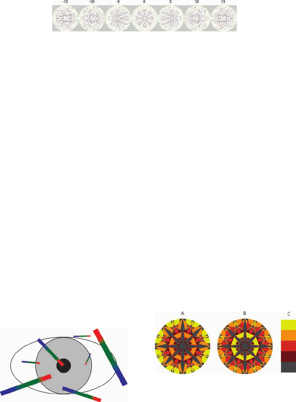
Fig. 17 Angular spectrum of a gemstone as projected in the hemisphere upon −15, − 10, −5, 0.0, 5,
10, and 15 deg tilts. This sequence shows that upon tilting a stone the probability of intersecting a
source by the angular spectrum is essentially one.
Fig. 18 The bigger the chromatic flares are, the larger the probabil-
ity is of being captured and clipped by the eye’s pupil.
Fig. 19 共a兲 Forward fire map, 共b兲 reverse fire map, and 共c兲 key: gray
indicates obscured, low-angle light or leakage. Dark orange indi-
cates a linear dispersion of 2.0 mm or less at the eye of the observer
共forward map兲 or at the source 共reverse map兲. Orange is dispersion
between 2.0 mm and 4.2 mm, light orange is dispersion between
4.2 mm and 6.4 mm, and yellow is dispersion larger than 6.4 mm for
the chosen wavelengths of 420 and 620 nm.
Sasian et al.: Evaluation of brilliance, fire, and scintillation in round brilliant gemstones
Optical Engineering September 2007/Vol. 46共9兲093604-7

An alternate view to contrast properties is shown in Fig.
13 where the hemisphere increases its illumination as the
azimuth range is increased from zero to 360 deg in 30-deg
increments and upon the face-up position.
5.4 Gem Fire
The phenomenon of fire is one of the most appealing ef-
fects in transparent gemstones. Under favorable conditions
fire makes individual facets appear fully colored with the
rainbow hues.
25,26
Fire inherently occurs due to the light
dispersion upon refraction as light enters and exits a stone.
Three factors determine the amount of fire perceived from a
facet, namely, the angular dispersion of light upon refrac-
tion from the gemstone, the angular subtend of the source,
and the angular subtend of the eye’s pupil in relation to the
facet.
To best observe fire it is required to have a localized
source of light so that its angular subtend is much smaller
than the angular dispersion produced by the gem facet, es-
sentially a point source. As different colored rays arrive to
the eye from a facet, some of them enter the eye’s pupil and
others are blocked producing a colored appearance of the
facet as shown in Fig. 14. In this process the boundary of
the eye’s pupil plays a critical role in obstructing portions
of the spectrum to achieve the colored facet appearance. At
250 mm of distance and considering the dispersion of dia-
mond, which is on the order of 0.044, wavelengths at 420
and 620 nm can be linearly spaced up to several millime-
ters by a gem. Depending on the illumination conditions
and the age of the observer, the human pupil size can range
from about 2 to 8 mm in size. Therefore there is some
variability on the amount of fire perceived by different ob-
servers in different illumination conditions.
Relative to the eye’s position, the angular subtend of a
given facet determines the appearance of the facet. If the
subtend of the facet is small, then only one color would be
observed across the facet. As the angular subtend of the
facet increases, more colors would be observed, until fi-
nally the entire spectrum would be seen. Essentially, the
eye would be observing the source at different lateral loca-
tions depending on the color as shown in Fig. 15. The facet
size would be large enough to permit the eye to see the
source at those different locations. However, gem facets are
typically small so that in the presence of fire they appear
substantially with a single color.
As the angular size of the source increases from a small
fraction of a degree to a few degrees the color saturation
will decrease. Intermediate colors such as green will disap-
pear first, then only blue and red will be observed, and
finally no colors will be observed. In this process of in-
creasing the source size, ray overlap from different loca-
tions in the source takes place, washing out the colored
appearance of the facet as shown in Fig. 16.
Modeling of gem fire can be done by assuming specific
localized illumination scenarios such as spot lighting or
chandelier illumination. However, gem evaluation may fa-
vor certain cuts that perform better in those specific illumi-
nation conditions. The approach to characterize fire fol-
lowed in this paper is based on the observation that the
angular spectrum of most realistic cuts is rich. When a
gemstone is in movement, for example, tilted back and
forth, its angular spectrum scans the hemisphere, resulting
in essentially a probability of one to intersect a given local-
ized light source. This observation is illustrated in Fig. 17,
which shows the angular spectrum of a gemstone that has
been tilted in the range of ±15 deg with respect to the
face-up position. The practical meaning of this observation
is that for evaluating fire one can factor out the illumination
conditions. Thus, our evaluation of fire is independent of
the source distribution. Appendix A provides further sup-
port with a study of the angular spectrum as a function of
stone cut parameters.
Fig. 20 Scintillation maps of a round brilliant with 共a兲 concentric
illumination and 共b兲 sector illumination. Concentric illumination
shows how the virtual facets are illuminated as a source scans ra-
dially the hemisphere. Sector illumination shows how the virtual fac-
ets are illuminated as a source scans in azimuth the hemisphere.
Fig. 21 Illumination key in the hemisphere with 共a兲 concentric illu-
mination over the medium angles, and 共b兲 sector illumination over
the medium angles. The colors used are red, green, blue, cyan,
magenta, and yellow.
Fig. 22 Glare maps of a round brilliant showing directions in the hemisphere that can contribute glare.
The maps are in tilt positions ranging from −30 to 30 deg in 5-deg intervals.
Sasian et al.: Evaluation of brilliance, fire, and scintillation in round brilliant gemstones
Optical Engineering September 2007/Vol. 46共9兲093604-8

Then, the next important factor in the production of fire
is the amount of dispersion that rays from facets in a gem’s
crown have. Gemstones at a distance of 250 mm possess
barely enough dispersion 共on the order of millimeters兲 to
separate the light colors across the observer’s pupil. The
amount of dispersion from each virtual facet is a significant
measure of fire. The larger the dispersion from a facet, the
higher the probability will be that the eye’s pupil will clip
dispersed rays to produce a colored appearance as shown in
Fig. 18. When there is a larger amount of dispersion, the
color perceived will be purer 共more color saturation兲 but
with a decrease in intensity. The decrease in color intensity
is not a concern due to the relatively high brightness of
localized sources that can produce fire.
Figure 19 shows what we call a fire map, which indi-
cates the potential of a stone to produce fire. It is actually a
dispersion map, coded by colors, that indicates the amount
of dispersion that a white-light ray will undergo in reaching
the observer’s eye at a distance of 250 mm in the face-up
position. Dark orange indicates a linear dispersion of
2.0 mm or less at the eye of the observer. Orange is disper-
sion between 2.0 mm and 4.2 mm, light orange is disper-
sion between 4.2 mm and 6.4 mm, and yellow is dispersion
larger than 6.4 mm for the chosen wavelengths of 420 and
620 nm. Fire maps are produced by tracing two rays per
crown position at different wavelengths and noting the
amount of dispersion. Two fire maps, for each stone geom-
etry, can be produced depending on the use of reverse
共from the eye to the source兲 or forward 共from the source to
the eye兲 ray tracing. Forward fire maps, produced in the
observer’s space, show the potential to observe fire. Re-
verse fire maps, produced in the source space, show the
potential to observe a source. The dispersion in the reverse
and forward fire maps is related by the anamorphic magni-
fication associated to the prism corresponding to each vir-
tual facet.
There are other factors that can determine fire in a gem-
stone, as for example the amount of light from higher-order
refractions that coincide with the primary refraction upon
exiting the gemstone. The structured lighting that results
from dynamic contrast and the inherent light scrambling
inside the gemstone are other factors that count. However,
the fire maps upon primary or higher-order refractions
共those that result from Fresnel ray split兲 convey signifi-
cantly the fire potential of a stone and are a valuable tool
for assessing gem fire.
5.5 Gem Scintillation
In the presence of brilliance and fire the most appealing
effect is gem scintillation. In this effect the fire pattern
Fig. 23 A matrix of ASET maps as a function of crown and pavilion
angles upon primary refraction. The highlighted diagonal lines rep-
resent the main cutter’s line 共slope of −1兲 and the anti-cutter’s line
共slope of +1兲. Note that illumination properties are similar along lines
parallel to the main cutter’s line. 共High-resolution image available
online only. 关URL: http://dx.doi.org/10.1117/1.2769018.1兴兲
Fig. 24 ASET matrix with 40 deg of obscuration upon primary re-
fraction. 共High-resolution image available online only. 关URL:
http://dx.doi.org/10.1117/1.2769018.2兴兲
Sasian et al.: Evaluation of brilliance, fire, and scintillation in round brilliant gemstones
Optical Engineering September 2007/Vol. 46共9兲093604-9

changes dynamically and flashes of white light are per-
ceived across the crown of the stone. Thus there are two
major scintillation effects, fire and flash scintillation. To
observe them it is required that the stone, the observer, or
the illumination conditions be in movement. Typically the
observer tilts the stone back and forth to observe scintilla-
tion and naturally optimizes for the direction that maxi-
mizes scintillation. Without brilliance, as defined in this
paper, there cannot be fire since no light can be brought to
the observer’s eyes. Without fire there cannot be fire scin-
tillation as defined by the change of fire pattern. Flash scin-
tillation can occur without fire scintillation and it is due to
light sources not small enough in angular subtend to pro-
duce fire, or to the inability of a stone to sufficiently dis-
perse light for a given position of the observer. White dif-
fused illumination will wash out both scintillation effects.
Sources that subtend a small angle will contribute more to
produce a flash effect, the rapid turn on and off of the light
from a given facet, than sources that subtend larger angles.
Thus fire scintillation is more vivid than flash scintillation.
The amount of gem scintillation perceived is linked to
the brilliance and fire of a stone. However, scintillation
strongly depends on the change of illumination conditions.
This change is primarily produced on purpose by the move-
ment of the stone as it is admired. The effects on scintilla-
tion due to the stone movement in turn can be enhanced
according to the intrinsic light scrambling properties of the
stone. These light scrambling properties of a stone are the
third mechanism to produce structured lighting. In this pa-
per we define the light scrambling properties of a stone as
its ability to mix or scramble its angular spectrum as it is
projected into the stone crown. In particular, attention is
paid to the scrambling of the medium angular range or reds
in the ASET maps.
Figure 20 shows what we call scintillation maps. These
maps are generated with light reaching the observer’s eye
in the face-up position from the medium angles, 45 to
75 deg, in the hemisphere and in a 60-deg sector as shown
in Fig. 21. They are presented in six colors 共red, green,
blue, cyan, magenta, and yellow兲 to further subdivide the
medium angles into regions that are concentric arc circles
or truncated pie sections. The interpretation of the scintil-
lation maps is different than the ASET maps. Recall that in
the ASET maps colors indicate the ray directions that can
make a stone crown appear illuminated. The scintillation
maps represent the change in illumination of the crown as a
light source scans, in azimuth or radially, the medium
angles in the hemisphere. A stone deemed to substantially
scramble light would appear with the colors well distrib-
uted over its crown in the scintillation map view. In Fig. 20
the size and form of the virtual facets is clearly shown as
well as the illumination distribution over the crown of the
gem. Thus a scintillation map conveys information about
Fig. 25 ASET matrix upon secondary refraction. 共High-resolution
image available online only.
关URL: http://dx.doi.org/10.1117/1.2769018.3兴兲
Fig. 26 ASET matrix produced with one half of the illumination
hemisphere. 共High-resolution image available online only. 关URL:
http://dx.doi.org/10.1117/1.2769018.4兴兲
Sasian et al.: Evaluation of brilliance, fire, and scintillation in round brilliant gemstones
Optical Engineering September 2007/Vol. 46共9兲093604-10

the size and form of the virtual facets and about the intrin-
sic light scrambling properties of a gem, and hints at how a
stone would exhibit scintillation.
5.6 Gem Leakage
Gem leakage refers to areas in the pavilion where total
internal reflection does not occur. Consequently and de-
pending on the light source, the light intensity from leaky
regions may not be as intense as in other regions in the
stone. In addition, in stones that are mounted in pronged
mounts it is possible for light to enter through the pavilion
and reach the observer’s eye by exiting though the crown.
Upon secondary refraction, leakage areas can also contrib-
ute to fire and scintillation given that localized sources are
bright. Leakage can be considered a detrimental effect,
though it is possible that small amounts of leakage that are
well distributed may add variety to the illumination effects
in a positive manner.
5.7 Gem Glare
Gem glare results from the reflection of a light source on
the surface of crown facets. This light does not enter the
stone and hides the appreciation of the main illumination
effects that are perceived inside the stone. Figure 22 shows
a series of glare maps that indicate, upon the face-up posi-
tion and tilt positions, the directions in the hemisphere that
can produce glare. Glare maps with significant glare from
the medium angles 共reds兲 are deemed undesirable; they cor-
respond to stones with shallower crown angles.
6 Map Matrices
In the previous section we have introduced several maps
that are useful in evaluating and comparing gemstones.
This section provides matrices of maps as a function of the
crown and pavilion angles for a given table size of a stan-
dard round brilliant cut. In this study the table size is 53%.
The maps give an ample view of the trade-offs in the cut
space as commented for each map. The horizontal axis cor-
responds to the crown angle ranging from 24.5 deg 共left兲 to
38.5 deg 共right兲 with 1.0-deg intervals. The vertical axis
corresponds to the pavilion angle ranging from 38.5 deg
共bottom兲 to 43.5 deg 共top兲 with 0.2-deg intervals. The maps
are generated with the primary refraction except as indi-
cated for some ASET and fire maps. It will become appar-
ent that the matrices show certain important trends in illu-
mination properties. The Tolkowsky cut is a reference cut
and is located at P41.7/C34.5 where P41.7 indicates a pa-
vilion angle of 41.7 deg and C34.5 a crown angle of
34.5 deg.
Fig. 27 Matrix of reverse fire maps upon primary refraction.
共High-resolution image available online only. 关URL:
http://dx.doi.org/10.1117/1.2769018.5兴兲
Fig. 28 Matrix of forward fire maps upon primary refraction.
共High-resolution image available online only. 关URL:
http://dx.doi.org/10.1117/1.2769018.6兴兲
Sasian et al.: Evaluation of brilliance, fire, and scintillation in round brilliant gemstones
Optical Engineering September 2007/Vol. 46共9兲093604-11

6.1 ASET Maps
Figure 23 shows a matrix of standard ASET maps 共30 deg
of obscuration兲 in the face-up position for the round bril-
liant cut. The matrix shows that there is a trade-off between
crown angle and pavilion angle. That is, a crown change of
1 deg can be traded-off by a pavilion angle change of about
0.2 deg to maintain the same properties to within some lim-
its. As far as brilliance is concerned this trade-off has been
known in the industry for some time. What is little known
is that the trade-off exists even for other properties as is
shown in the matrices describing other illumination effects.
Given the steps in the vertical and horizontal axis the stones
appear to have similar properties along lines running at
45 deg 共slope of −1兲 from top to bottom. The 45 deg 共slope
of −1兲 line passing by the Tolkowsky cut is called the main
cutter’s line. This line gives insight to diamond cutters
about how to adjust the crown angle for a given pavilion
angle change and represents a trade-off in stone cutting.
Other lines at 45 deg that are parallel to the main cutter’s
line are called cutter’s lines. A line perpendicular to the
main cutter’s line 共slope of +1兲 and that also passes by the
Tolkowsky cut is called the anti-cutter’s line. The recogni-
tion of the cutter’s trade-off simplifies considerably the
analysis of gemstones. The main differences in stone be-
havior within reasonable limits appear along the anti-
cutter’s line. Thus the cutter’s trade-off reduces the analysis
from an N-dimensional to an 共N −1兲-dimensional analysis.
Both the main cutter’s line and the anti-cutter’s line are
highlighted in the matrices.
The ASET maps are the most important descriptors of
illumination performance given that they characterize bril-
liance and contrast. The maps with significant reds and
some well-distributed blues are the stones that are deemed
to perform the best. The stones on the lower left are bril-
liant but, as discussed below, suffer from some problems.
One of these problems is that upon stone tilt the girdle as
reflected by the pavilion appears in the table. In the ex-
treme, these types of stones are called fish-eyes. The bril-
liant stones near the Tolkowsky and along the main cutter’s
line are the best performers. Note that the Tolkowsky cut
appears to be near a boundary where the stones change
properties.
Stones with significant blues in the table are called nail-
heads because the table appears dark due to light retrore-
flection and/or obscuration upon close examination. The
stones with significant greens will tend to lack brilliance in
the bezel and structured lighting. Some other stones have
significant leakage as shown by the gray regions.
The matrix of ASET maps also supports the choice of
angular ranges to subdivide the hemisphere. For example,
the low angles 共greens兲 are mainly distributed over the be-
zel and have a poor distribution over the crown of stones in
Fig. 29 Matrix of reverse fire maps upon secondary refraction.
共High-resolution image available online only. 关URL:
http://dx.doi.org/10.1117/1.2769018.7兴兲
Fig. 30 Matrix of forward fire maps upon secondary refraction.
共High-resolution image available online only. 关URL:
http://dx.doi.org/10.1117/1.2769018.8兴兲
Sasian et al.: Evaluation of brilliance, fire, and scintillation in round brilliant gemstones
Optical Engineering September 2007/Vol. 46共9兲093604-12

the matrix. The stones in the top right corner of the ASET
map matrix are the ones that contribute more low-angle
light. Thus low-angle light does not significantly contribute
to brilliance or structured lighting. In regard to the high
angle 共blues兲, its distribution and amount can be significant;
however, its angular range is essentially set by the extent of
the observer’s obscuration.
Figure 24 shows a matrix of ASET maps for 40 deg of
obscuration, which illustrates how the contrast properties
hold or change upon a closer examination of the stone.
Note that the only stones that exhibit a positive contrast
pattern change are the ones near the Tolkowsky cut along
the main cutter’s line. Other cuts like the nail-heads de-
velop excessive contrast. Some of the cuts with no contrast
remain without contrast. The ASET maps with 40 deg of
obscuration also convey the structured lighting abilities of
gems.
Figure 25 shows a matrix of ASET maps upon the sec-
ondary refraction. The main feature of this matrix is that it
shows that cuts along the main cutter’s line remain brilliant
upon the secondary refraction. In addition, the contrast
properties also remain positive. Stones along the anti-
cutter’s line change significantly in their contribution to
brilliance. The shallow crown, shallow pavilion stones on
the left corner are not considered brilliant upon the second-
ary refraction given that they contribute light from the
Fig. 31 Matrix of scintillation maps upon primary refraction.
共High-resolution image available online only. 关URL:
http://dx.doi.org/10.1117/1.2769018.9兴兲
Fig. 32 Matrix of scintillation maps upon secondary refraction.
共High-resolution image available online only. 关URL:
http://dx.doi.org/10.1117/1.2769018.10兴兲
Fig. 33 Tilt view matrix of ASET maps upon primary refraction
along the anti-cutter’s line. 共High-resolution image available online
only. 关URL: http://dx.doi.org/10.1117/1.2769018.11兴兲
Sasian et al.: Evaluation of brilliance, fire, and scintillation in round brilliant gemstones
Optical Engineering September 2007/Vol. 46共9兲093604-13

Fig. 34 Tilt view matrix of forward fire maps upon primary refraction
along the anti-cutter’s line. 共High-resolution image available online
only. 关URL: http://dx.doi.org/10.1117/1.2769018.12兴兲
Fig. 35 Tilt view matrix of scintillation maps upon primary refraction
along the anti-cutter’s line 共concentric illumination兲. 共High-resolution
image available online only.
关URL: http://dx.doi.org/10.1117/1.2769018.13兴兲
Fig. 36 Tilt view matrix of scintillation maps upon primary
refraction along the anti-cutter’s line 共sector illumination兲.
共High-resolution image available online only. 关URL:
http://dx.doi.org/10.1117/1.2769018.14兴兲
Fig. 37 Tilt view matrix of ASET maps upon primary refraction
along the cutter’s line. 共High-resolution image available online only.
关URL: http://dx.doi.org/10.1117/1.2769018.15兴兲
Sasian et al.: Evaluation of brilliance, fire, and scintillation in round brilliant gemstones
Optical Engineering September 2007/Vol. 46共9兲093604-14

lower angles 共greens兲. Note also that the pavilion-crown
angle trade-off holds to a lesser extent upon the secondary
refraction.
A useful modification of the ASET maps is the half-
ASET map produced with half the hemisphere obscured.
Figure 26 shows a matrix of half-ASET maps. Under half-
hemisphere illumination the structured lighting produced
by the intrinsic properties of the cut are revealed. Stones at
or near the main cutter’s line retain positive contrast char-
acteristics. Other stones, as for example the shallow crown,
shallow pavilion stones, exhibit a half nail-head contrast
pattern and lack brilliance. The stones on the top right cor-
ner of the matrix lack brilliance in the bezel and are leaky.
6.2 Fire Maps
Figures 27 and 28 show matrices for reverse and forward
fire maps, respectively. The reverse fire map shows the po-
tential to observe a light source given that the chromatic
flare 共the spread of light into a spectrum兲 covers a larger
area in the hemisphere, which increases the probability of
intersecting a given light source. The forward fire map
shows the potential to observe fire given that the larger the
chromatic flare, the larger the probability is that the eye’s
pupil would clip and capture light from a facet. Forward
fire maps are considered the main tool to assess the gem’s
intrinsic fire potential 共without considering the source dis-
tribution and observer兲.
Both reverse and forward fire maps maintain the trade-
off between crown and pavilion angles along the cutter’s
lines. The stones that exhibit significant fire are along the
main cutter’s line. These stones have the property of exhib-
Fig. 38 Tilt view matrix of forward fire maps upon primary refraction
along the cutter’s line. 共High-resolution image available online only.
关URL: http://dx.doi.org/10.1117/1.2769018.16兴兲
Fig. 39 Tilt view matrix of scintillation maps upon primary refraction
along the cutter’s line 共concentric illumination兲. 共High-resolution
image available online only.
关URL: http://dx.doi.org/10.1117/1.2769018.17兴兲
Fig. 40 Tilt view matrix of scintillation maps upon primary refraction
along the cutter’s line 共sector illumination兲. 共High-resolution image
available online only. 关URL: http://dx.doi.org/10.1117/1.2769018.18兴兲
Sasian et al.: Evaluation of brilliance, fire, and scintillation in round brilliant gemstones
Optical Engineering September 2007/Vol. 46共9兲093604-15

iting relatively high dispersion in the table. Other stones
that have high dispersion are in the lower-left and top-right
corners of the fire matrices. However, these stones suffer
from not having high dispersion in the table.
The fire matrices show that the old diamond-cutting in-
dustry rule of increasing the crown angle to achieve more
fire is not necessarily true. It only significantly applies to
stones at or near the main cutter’s line or about lines pass-
ing by other regions such as the left-bottom and top-right
corners.
Fire results from higher dispersion and this mainly hap-
pens in the stone bezel. Table fire is rare and stones with
significant bezel and table fire are considered superior.
Some stones that exhibit significant fire
27
are designed with
a small table to maximize the bezel area and therefore fire.
Figures 29 and 30 show some matrices for reverse and
forward fire maps upon secondary refraction, respectively.
The matrix for reverse fire exhibits significantly more dis-
persion than the matrix for forward fire. However, in both
matrices the stones near or at the main cutter’s line appear
with significant fire potential.
6.3 Scintillation Maps
Figure 31 shows a scintillation matrix produced upon the
face-up position. Each of the virtual facets that captures
light from the hemisphere appears colored and this is
termed a scintillation event. The first measure of scintilla-
tion potential is brilliance 共reds in the ASET maps兲, given
that for scintillation to occur the stone must be able to
redirect light to the observer’s eye. The stones that have
more well-distributed scintillation events in color and over
the stone’s crown have the potential to produce more scin-
tillation than stones with lesser events. For example, Fig.
31 shows that stones at or near the main cutter’s line have
spatially well-distributed events as compared to other
stones.
Figure 32 shows a scintillation matrix upon secondary
refraction. This matrix shows that the virtual facets become
smaller and scintillation may appear as a pinpoint effect
upon localized bright sources. Given that light upon sec-
ondary refraction is reflected more times inside the stone,
the scintillation appears as more rapidly changing com-
pared to scintillation from the primary refraction.
7 Tilt Views
Although the maps in the face-up position are a primary
tool for evaluating gemstones, they do not provide suffi-
cient information about the performance of a stone as it
moves. The tilt-view matrices that we present below pro-
vide a view of the gem properties as a function of the tilt
with respect to the hemisphere and the observer. The tilt
views are generated by tilting the stone from −30 deg to
30 deg in 3-deg increments. Figures 33–36 show the tilt
views for the round brilliant cut along the anti-cutter’s line
for ASET maps, forward fire maps, and scintillation maps.
Figures 37–40 show the tilt views along the cutter’s line. In
the tilt views the Tolkowsky cut is highlighted for ease of
identification.
The scintillation tilt maps are generated by tilting the
stone along the symmetry line of the illuminating, truncated
pie sector in the hemisphere as shown in Fig. 41. This is
equivalent to tilting a stone forward and backward as it is
observed. The top maps 共−15 to −30 deg of tilt兲 in the tilt
view correspond to the backward tilts, the middle map to
the face-up position, and the bottom maps 共+15 to +30 deg
of tilt兲 to the forward tilts. It can be appreciated that the
larger number of scintillation events occur upon the face-up
position 共no tilt兲 and forward tilts to about 15 deg. The
scintillation events observed in the tilt maps correspond to
Fig. 41 共A兲 Forward and backward tilts in relation to the observer and source, and 共B兲 left and right tilts
in relation to the observer and source.
Fig. 42 Tolkowsky cut, ASET map, lower girdle facets length 60%,
star facets length 35%.
Sasian et al.: Evaluation of brilliance, fire, and scintillation in round brilliant gemstones
Optical Engineering September 2007/Vol. 46共9兲093604-16

the events that one would observe when the stone is tilted
quickly left to right while holding it at a given forward-
backward tilt position.
In the scintillation tilt maps a light source is assumed to
be located above and behind the head of the observer. The
exact location and size of the light source does not change
qualitatively the series of scintillation events seen in the tilt
view maps. These scintillation events are concentrated in
the table when the stone is tilted forward, spread over the
crown as the stone has less tilt, and then appear in the bezel
共left and right bezel areas兲 as the stone is tilted backward.
Thus the tilt-view scintillation maps represent in a color-
coded manner what an observer would actually see in ex-
amining a stone. The number of events and their distribu-
tion in the scintillation tilt views indicate the scintillation
properties of a stone.
The tilt-view ASET maps along the anti-cutter’s line,
Fig. 33, show that the best performers in terms of contrast
and brilliance are located at the main cutter’s line and pos-
sibly at the left and right adjacent lines. The tilt-view for-
ward fire maps, Fig. 34, indicate that, in terms of fire po-
tential, stones in the cutter’s line and in the line to the right
exhibit the best fire. The scintillation tilt views, Figs. 35
and 36, show that stones along the main cutter’s line have
the best scintillation as indicated by the number and distri-
bution of events. Thus the cutter’s trade-off and the tilt
views permit one to determine the cutter’s line where the
best round brilliant cuts are located. These cuts are located
along the main cutter’s line.
The tilt views along the cutter’s line, Figs. 37–40, permit
one to determine which are the best stones in terms of
illumination performance. The tilt-view ASET maps along
the cutter ’s line, Fig. 37, show that the Tolkowsky cut, the
two to the left 共P40.9/C33.5 and P41.1/C32.5兲, and the one
to the right 共P40.5/C35.5兲 are the best in terms of contrast
pattern and brilliance. The tilt-view, forward fire maps, Fig.
38, indicate that in terms of fire potential the stones in the
main cutter’s line, the Tolkowsky, and the next four stones
exhibit the best fire. The scintillation tilt-view maps, Figs.
39 and 40, show that stones that exhibit the best scintilla-
tion are the last seven in the main cutter’s line given the
better distribution of scintillation events at tilts around the
face-up position. Considering the ASET, fire, and scintilla-
tion maps the four best round brilliant stones 共table 53%兲
are P40.9/C33.5, P40.7/C34.5 共Tolkowsky兲, P40.5/C35.5,
and P40.3/C36.5.
For completeness of analysis Appendix A provides ad-
ditional tilt matrices along the main cutter’s line and anti-
cutter’s line.
8 The Tolkowsky Cut
Tolkowsky
1
described the reasoning that he followed to ar-
rive at the proportions of one of the best cuts for a round
brilliant. In his research he was guided by the proportions
of stones that were known to exhibit superior performance.
His research supported the knowledge that cutters, by trial
and error, had generated over time. In his statement “…we
conclude that the correct value for the pavilion angle is 40
degrees and 45 minutes and gives the most vivid fire and
greatest brilliancy, and that although a greater angle would
give better reflection, this would not compensate for the
loss due to the corresponding reduction in dispersion” it
becomes apparent that Tolkowsky noted that his cut is a
compromise between brilliance and dispersive properties.
In fact, contrast and scintillation are part of the overall
balance. The compromise is clearly shown in the tilt views
along the main cutter’s line. Tolkowsky and the cut industry
advocate high dispersion to achieve fire, which is consistent
with our research and fire maps. From Tolkowsky’s time
the round brilliant cut has been improved
3
by increasing the
girdle thickness, including girdle facets, reducing the culet
size, and increasing the length of the lower girdle facets
and star facets. Figures 42–44 show a study in lower girdle
length and star facets. Figure 42 shows the old round bril-
liant cut with large virtual facets in the table 共lower girdle
facets length 60%, star facets length 35%兲, Fig. 43 shows
the modern cut with a balanced virtual facet size that favors
the effect of facet interplay 共lower girdle facets length 80%,
star facets length 50%兲, and Fig. 44 shows the round bril-
liant cut with thin pavilion mains 共lower girdle facets
length 90%, star facets length 50%兲.
The Tolkowsky cut and other cuts along the main cut-
ter’s line have some amount of leakage in the bezel. One
way to reduce or avoid this leakage is by the technique
called painting
28,29
in which the facet angle between the
upper girdle facets and the kite facets is reduced. Depend-
ing on the length of the star facets, painting can have a
Fig. 43 Tolkowsky cut, ASET map, lower girdle facets length 80%,
star facets length 50%.
Fig. 44 Tolkowsky cut, ASET map, lower girdle facets length 90%,
star facets length 50%.
Sasian et al.: Evaluation of brilliance, fire, and scintillation in round brilliant gemstones
Optical Engineering September 2007/Vol. 46共9兲093604-17

negative impact on dispersion. Stones along the cutter’s
line can be painted more without negative dispersion ef-
fects.
9 Evaluation of Fancy Shape Cuts
The methodology developed to characterize illumination
effects discussed below can also be applied to study fancy
shape gems such as the princess and emerald cuts. Some
fancy shapes have less symmetry than the eightfold sym-
metry of the round diamond and others more, for example,
fourfold and ninefold symmetry. Therefore the angular
spectrum of some fancy cuts may not be as rich as it is for
the round brilliant cut and additional angular ranges in el-
evation and in azimuth could be necessary to sufficiently
assess the illumination properties. It is also possible to have
fancy cuts with richer angular spectra than the angular
spectrum of round brilliants. Each fancy cut requires a
study by itself. However, the maps and concepts developed
in our research can still be applied for evaluating fancy
cuts. For example, using our methodology we have identi-
fied a princess and an emerald cut as shown in Figs. 45 and
46 that upon actual fabrication
30,31
resulted in stones that
displayed superior fire and brilliance. These cuts have not
been previously known to the industry and their specifica-
tions are given in Appendix B.
10 ASET Instrument
We have developed an instrument called the Angular Spec-
trum Evaluation Tool 共ASET兲 to practically evaluate gems
and demonstrate results obtained by ray tracing of virtual
gems. The ASET instrument is shown in Fig. 47 and con-
sists of a stage where the gem is placed, a hemisphere
carrying the colors according to angular range, a light
source, and a camera. Figure 48 shows an actual photo-
graph through the ASET of a round brilliant gem and its
corresponding ray-traced computer generated view. Note
the significant match between the real and virtual ASET
images.
One way to observe dispersion is by creating an illumi-
nation scenario with a plurality of white sources
32
distrib-
uted over the illuminating hemisphere. The ASET instru-
ment can be modified to display light dispersion as shown
in Fig. 49. The modification requires placing a plurality of
white light sources over the medium angles in the hemi-
sphere. This is actually produced by placing a screen with
pinholes in front of a light diffuser and a broad, white-light
source. The angular separation of the pinholes in the screen
is about the same as the angular dispersion produced by the
gem. In this manner the colors produced by a single light
source are not washed out by the overlap with colors from
an adjacent source. However, the pinholes are still close
enough to essentially always have light from a pinhole il-
luminating each virtual facet. An additional aperture in
front of a camera serves the same function as the eye pupil
in clipping colored rays. By closing or opening this aper-
ture, more or less saturation in the colored facets can be
achieved. It is not possible to directly generate fire maps.
However, the colors and color saturation in the views gen-
erated are in agreement with fire maps. For example, Fig.
50 shows a sequence of photographs of a round brilliant
where the clipping aperture is varied in size; the corre-
sponding fire map is also shown. Note that the actual pho-
tographs show the crown bezel with more saturated colors.
This can be explained from the higher dispersion shown in
the bezel by the fire map.
11 Real Versus Virtual Gemstones
The study presented in this paper has been done in a com-
puter using virtual gemstones that are perfect in their pro-
portions and symmetry. Real gems are not perfect in their
geometry and suffer from several problems such as facet
Fig. 45 共a兲 ASET map, 共b兲 ASET map 共40 deg of obscuration兲, 共c兲 forward fire map, and 共d兲 photo-
graph of a high-performing princess cut.
Fig. 46 共a兲 ASET map, 共b兲 ASET map 共40 deg of obscuration兲, 共c兲 Forward fire map, and 共d兲 photo-
graph of a high-performing emerald cut.
Sasian et al.: Evaluation of brilliance, fire, and scintillation in round brilliant gemstones
Optical Engineering September 2007/Vol. 46共9兲093604-18

position and angular misalignment. These misalignments
reduce gem symmetry and impact the illumination perfor-
mance. One problem is that facet misalignment can reduce
the size of the virtual facets to promote pinpoint effects at
the expense of the facet interplay effect. Some light scat-
tering can also take place at facets that do not meet as
expected. Nevertheless, well-cut gems do not have signifi-
cant errors to make the analysis in this paper unrealistic.
For example, Fig. 51 shows a study of a real gem upon the
face-up position and ±15-deg tilt position and Fig. 52
shows the same study for the corresponding perfect virtual
model. Our ray-tracing methodology is discussed in Appen-
dix C.
12 Summary of Illumination Effects
Our study is based on the actual observation of several
effects that depend on the illumination conditions and on
how structured illumination is produced. When a well-cut
gemstone is observed and no or little light is redirected to
the observer, the gemstone appears unilluminated. As broad
and diffuse illumination is redirected to the observer’s eyes,
the stone becomes illuminated and contrast patterns take
place as shown in Figs. 11 and 13. In the presence of lo-
calized sources of white light that subtend several degrees,
say 3 to 12 deg, several facets across the crown become
distinctly brighter. Some facets may appear lightly colored.
In the presence of localized sources of white light that sub-
tend an angle of 1 deg or less, some facets appear colored
with intense colors of the visible spectrum. Facets that re-
direct light from localized bright sources appear as light
sources themselves. Light directly reflected from the crown
facets contributes glare and prevents observation of the ef-
fects taking place inside the gemstone. Upon movement of
the gem, typically the tilting of the gem left to right, or
tilting it backward and forward, the effects of dynamic con-
trast, flash and fire scintillation, and facet interplay take
place. Pinpoint fire and pinpoint white flashes are also ob-
served. The dynamic nature and the overall combination of
all these effects is known as the life of the gemstone.
13 Conclusions
This paper develops a methodology for evaluating bril-
liance, fire, and scintillation in gemstones. The study is
devoted to the round brilliant cut and the concepts and tools
developed can be also applied to evaluate fancy cuts. We
have highlighted the illumination effects of brilliance, con-
trast and dynamic contrast, fire, fire and flash scintillation,
virtual facets, facet interplay, and leakage. The concept of
geometrical angular spectrum has been introduced to under-
stand how the cut and the illumination conditions impact a
gem’s appearance. We have developed ASET maps, fire
maps, scintillation maps, and glare maps. These maps con-
vey information about the illumination attributes of interest.
The ASET maps show the ray directions that can make a
gem to appear illuminated, that is, brilliant. In addition,
they show how the obscuration of light by the observer’s
head plays an important role in creating structured illumi-
nation. We emphasize that creating structured lighting is
Fig. 47 共a兲 ASET instrument and 共b兲 schematic diagram.
Fig. 48 Comparison of ASET photograph of a real gem 共a兲 and the computer-generated ASET image
共b兲.
Fig. 49 Modification of the ASET instrument to display fire.
Sasian et al.: Evaluation of brilliance, fire, and scintillation in round brilliant gemstones
Optical Engineering September 2007/Vol. 46共9兲093604-19

crucial in producing illumination appeal in gemstones. We
have found out that the angular spectrum of the round bril-
liant cut is rich enough that, in movement, the probability
of aiming at a given light source is high. Therefore and for
comparison purposes, the phenomenon of fire is mainly de-
pendent on the light dispersion produced by a gem. Thus,
the fire maps that we have introduced show the potential of
a given gem to exhibit fire. The scintillation maps presented
show the intrinsic light scrambling properties of a given cut
and simulate the appearance of a stone as it is observed.
The light scrambling contributes to the creation of struc-
tured lighting and in turn to the creation of scintillation. We
have divided scintillation into fire and flash scintillation.
The map matrices that are presented show upon face-up
position how the illumination properties vary as a function
of crown and pavilion angles. We have noted that the cut-
ter’s trade-off extends not only to brilliance properties but
also to fire and scintillation properties. In particular, we
introduced the anti-cutter’s line where stone properties sig-
nificantly change and the cutter’s lines where properties are
kept substantially the same. The main cutter’s line contains
the stones with best illumination properties. As a result of
noting the cutter’s trade-off, the problem of finding the best
stones is simplified by one dimension in the cut space.
We have introduced tilt views along the anti-cutter’s line
and along the main cutter’s lines that permit one to find out
Fig. 50 Photographs of a round brilliant showing light dispersion as a function of the size of the
clipping aperture. Camera f stops: 共a兲 f/10, 共b兲 f/ 20, 共c兲 f/30, 共d兲 f / 40, and 共e兲 the corresponding fire
map is also shown for reference.
Fig. 51 Tilt study of a real gemstone at −15, 0, and +15 deg.
Fig. 52 Tilt study of the correspondent perfect virtual gemstone at
−15, 0, and +15 deg.
Sasian et al.: Evaluation of brilliance, fire, and scintillation in round brilliant gemstones
Optical Engineering September 2007/Vol. 46共9兲093604-20

Fig. 53 Tilt view of the angular spectrum upon the primary refrac-
tion along the main cutter’s line. 共High-resolution image available
online only. 关URL: http://dx.doi.org/10.1117/1.2769018.19兴兲
Fig. 54 Tilt view of the angular spectrum upon the primary refrac-
tion along the anti-cutter’s line. 共High-resolution image available on-
line only. 关URL: http://dx.doi.org/10.1117/1.2769018.20兴兲
Fig. 55 Tilt view ASET maps with 40 deg of obscuration and upon
the primary refraction along the main cutter’s line. 共High-resolution
image available online only.
关URL: http://dx.doi.org/10.1117/1.2769018.21兴兲
Fig. 56 Tilt view ASET maps with 40 deg of obscuration and upon
the primary refraction along the anti-cutter’s line. 共High-resolution
image available online only.
关URL: http://dx.doi.org/10.1117/1.2769018.22兴兲
Fig. 57 Tilt view, dynamic contrast along the main cutter’s line.
共High-resolution image available online only. 关URL:
http://dx.doi.org/10.1117/1.2769018.23兴兲
Sasian et al.: Evaluation of brilliance, fire, and scintillation in round brilliant gemstones
Optical Engineering September 2007/Vol. 46共9兲093604-21

which is the most brilliant, the most dispersive, and the
most scintillating stone. These tilt views clearly show the
Tolkowsky cut as a compromise between contrast-brilliance
properties and fire properties.
The maps have been generated by tracing rays in virtual
gems. Quantitative data can be extracted directly from ray
tracing to form metrics for gem qualitative evaluation. We
have defined some metrics in terms of percentages of ray
directions per crown zone, in terms of average dispersion
per crown zone, and in terms of virtual facet distribution by
crown zone. The value of these metrics as it refers to their
ability to measure realistic illumination attributes is a sub-
ject of continued study. In addition, how the metrics are
used for the purposes of gemstone grading is important and
will be the subject of a future paper.
We also have developed the ASET instrument, which
produces actual angular spectrum maps. These maps have a
strong correlation with computer-generated maps. Of prac-
tical importance is the ray-tracing methodology that we
have developed for generating the maps. Essentially, ray-
tracing speed has been accelerated and the maps can be
generated in a fraction of a second even though nonsequen-
tial ray tracing is involved for tracing the typically 40,000
rays needed for each map. The methodology and concepts
that we have developed can also be applied for evaluating
fancy cuts provided that the reduction in angular spectrum
is accounted by further subdivision of the illuminating
hemisphere.
Overall, we have developed understanding in the main
mechanics by which gems exhibit the illumination at-
tributes of brilliance, fire, and scintillation. We also have
introduced a variety of maps that are valuable for assessing
gem illumination performance. These maps are a valuable
education tool in the jewelry industry. With the body of
knowledge presented in this paper a gem appraiser can
readily and substantially evaluate the gem attributes of bril-
liance, fire, and scintillation.
Appendix A: Tilt Views along the Main Cutter’s
Line and Anti-cutter’s Line
For completeness Figs. 53–60 provide additional angular
spectrum maps and tilt views.
Appendix B: Gem Specifications
Tables 1 and 2 show the specifications for a high-
performance princess and emerald cut.
Appendix C: Ray Tracing
Analysis of gemstones involves nonsequential ray tracing
in which an algorithm searches for the next facet to inter-
sect after a given ray has encountered a facet. The order in
which a ray intersects facets is not specified in advance but
determined as the ray proceeds. This search after each ray
intersection significantly slows down the ray-tracing pro-
cess. Ray-tracing speed is a critical issue to render infor-
mation nearly instantaneously, for real-time animations and
Fig. 58 Tilt view, dynamic contrast along the anti-cutter’s line.
共High-resolution image available online only. 关URL:
http://dx.doi.org/10.1117/1.2769018.24兴兲
Fig. 59 Contrast around the hemisphere upon the face-up position
and along the main cutter’s line. 共High-resolution image available
online only. 关URL: http://dx.doi.org/10.1117/1.2769018.25兴兲
Fig. 60 Contrast around the hemisphere upon the face-up position
and along the anti-cutter’s line. 共High-resolution image available on-
line only. 关URL: http://dx.doi.org/10.1117/1.2769018.26兴兲
Sasian et al.: Evaluation of brilliance, fire, and scintillation in round brilliant gemstones
Optical Engineering September 2007/Vol. 46共9兲093604-22

Fig. 61 High-performance princess cut and its constructional parameters.
Fig. 62 High-performance emerald cut and its constructional parameters.
Fig. 63 Very large, very fine ASET matrix. 共High-resolution image
available online only. 关URL: http://dx.doi.org/10.1117/1.2769018.27兴兲
Fig. 64 Very large, very fine forward fire map matrix. 共High-
resolution image available online only. 关URL:
http://dx.doi.org/10.1117/1.2769018.28兴兲
Sasian et al.: Evaluation of brilliance, fire, and scintillation in round brilliant gemstones
Optical Engineering September 2007/Vol. 46共9兲093604-23

for searches through the design space. Standard nonsequen-
tial ray tracing may take tens of seconds to produce a single
ASET map, which requires about 40,000 rays to achieve
proper resolution. This speed is considered slow and im-
proper for real-time animations. One way to speed up the
image rendering is by the use of polygonal ray tracing
where the vertices of convex regions are identified and then
ray traced. This significantly reduces the number of rays
that need to be traced since the interior of the polygons are
painted with a color derived from vertex information. Po-
lygonal ray tracing requires finding out how a beam of light
is partitioned into polygons as it enters and propagates
through a gemstone. Other issues in ray tracing gemstones
are modeling and rendering.
33,34
We have chosen not to perform polygonal ray tracing
but accelerate our non-sequential ray tracing by using the
concept of path memory. In this concept the path of the
next ray to be traced is guessed to be the path of the pre-
vious ray, which is stored in memory. Then the ray is traced
in sequential mode with the path already stored in memory.
If this guess is incorrect then the ray-tracing engine as-
sumes a nonsequential mode. By doing the ray tracing in a
spiral curve, starting at the center of the gem table, it is
possible to produce an ASET map in less than 1 s. The
spiral curve passes by every pixel that needs to be painted
with a color that depends on the information obtained by
the ray trace.
A second improvement in speed results from the obser-
vation that the virtual facets of a gemstone are geometri-
cally convex regions. That the virtual facets are convex is
explained by the fact that the intersection of convex regions
is also convex. That is, when a beam of light enters a gem-
stone it is partitioned into convex regions since the facets
are convex. The partitioned convex beam remains convex
as it is further partitioned by convex regions. Therefore,
rather than ray tracing pixel by pixel in a spiral curve, we
trace the vertex pixels in a spiral with a width of a few
pixels that is divided into triangles. After proper checks,
groups of pixels can be colored according to information
derived from the vertices. This bears some similarity to
polygonal ray tracing except that there is no need to deter-
mine how the beam is partitioned into polygons.
As an example of the use of accelerated ray tracing we
present Fig. 63, which is called a very large, very fine
共VLVF兲 dense ASET matrix. The dense matrix contains an
array of 250 by 250 of individual ASET maps for the par-
ticular constructional parameters of a princess cut. The gen-
eration of a VLVF dense matrix permits one to identify
regions in the cut space containing gemstones that are bril-
liant. By also creating a VLVF fire-map matrix, as shown in
Fig. 64, and comparing it to the VLVF ASET matrix, one
can look for common areas that are brilliant and fiery. The
VLVF dense matrices are a valuable searching tool given
that gemstone cuts have many degrees of design, which
produce a large number of combinations that greatly grows
with each design parameter added.
Ray-tracing at two wavelengths for fire-map creation has
the problem that rays at different wavelengths may intersect
different facets rather than following the same sequence of
facets. To reduce this problem our Fire Maps were gener-
ated by tracing rays at wavelengths 519 nm and 521 nm
and then the results were scaled to approximate the disper-
sion at the chosen wavelengths of 420 nm and 620 nm.
Acknowledgments
We would like to thank the American Gem Society and
JCK Magazine for supporting this research and acknowl-
edge the expertise that our colleagues have shared with us.
Gabi Tolkowsky has shared his views about diamond
beauty. Sergei Sivovolenko from Octonus and Yuri Shele-
mentiev from the Moscow State University have shared
their many years of experience in understanding illumina-
tion effects in gemstones. Martin Haske from the Adamas
Gemological Laboratory has provided useful suggestions
and has been a valuable critic of our methodology. Gary
Holloway has raised many useful issues about diamond cut-
ting that have impacted our views. Bruce Harding, who first
determined that an observer affects the appearance of a
gemstone, has provided significant help in the area of gem-
stone cutting. Michael Cowing from ACA Gem Laboratory
has brought to our attention the importance of contrast and
brightness in creating brilliance in gemstones. We thank Al
Gilbertson from the Gemological Institute of America and
Richard von Sternberg from EightStar Diamond Company
for sharing their pioneering work about the color coding of
angular ranges in gemstone evaluation. The published pa-
pers from researchers at the Gemological Institute of
America provided clues and insights into gemstone appear-
ance. The work on gemstone fire of Anton Vasiliev, from
LAL Co. in Moscow, has been very helpful. Special ac-
knowledgements are given to all diamond cutters because
their insightful work in creating gemstone beauty is usually
not recognized.
Table 1 Princess Cut 共see Fig. 61兲.
Table % Crown 1 Crown 2
Pavilion
1
Pavilion
2
Upper
Pavilion
Ratio
a
Lower
Pavilion
Ratio
a
66% 37.3
deg
34.5
deg
60.3
deg
39.2
deg
65% 12%
a
The pavilion is cut with three tiers of chevron facets.
Table 2 Square emerald 共see Fig. 62兲.
Table %
Corner
Ratio
Crown
1
Crown
2
Crown
3
Pavilion
1
Pavilion
2
Pavilion
3
47.6% 22.9% 46.9
deg
40.0
deg
34.0
deg
47.6
deg
39.2
deg
31.2
deg
Sasian et al.: Evaluation of brilliance, fire, and scintillation in round brilliant gemstones
Optical Engineering September 2007/Vol. 46共9兲093604-24
References
1. M. Tolkowsky, Diamond Design: A Study of the Reflection and Re-
fraction of Light in a Diamond, Spon & Chamberlain, New York
共1919兲, 具http://www.folds.net/diamond_design/index.html典.
2. T. Shigetomi and K. Inoue, “Device for judging brilliancy of precious
stones as diamonds or the like,” U.S. Patent No. 4,647,194 共1987兲;a
description of the FireScope
®
is given by R. Von Sternberg, “Today’s
Revolution in Diamond Cutting,” 共2002兲, 具http://www.eightstar.com/
images/Eightstar_Diamond.pdf典.
3. A. Gilbertson, “Device for judging symmetry, brightness, and effi-
ciency of light return in precious stones,” U.S. Patent No. 6,795,171
共2004兲; see also, A. Gilbertson Letting Light Speak for Iitself: An
Introduction to Diamond Cut Grading, Diamond Profile, Inc., Port-
land, Oreg. 共1998兲.
4. J. Sasian, P. Yantzer, and T. Tivol, “The optical design of gemstones,”
Opt. Photonics News 14共4兲, 24–29 共Apr. 2003兲.
5. A. B. Meinel and E. S. Meinel, “Investigation of the optical behavior
of brilliant cut diamonds,” report to Helio Associates, Tucson, Ari-
zona 共1974兲.
6. B. Harding, “Faceting limits,” Gems. Gemol. 15共3兲 78–88 共Fall
1975兲, 具http://lgdl.gia.edu/pdfs/gemsandgemology/freebackissues/
fall_1975.pdf典.
7. B. Harding, “Diamond design revisited,” 具http://www.gemology.ru/
cut/english/tolkow2典.
8. J. S. Dodson, “A statistical assessment of brilliance and fire for the
round brilliant cut diamond,” Opt. Acta 25共8兲, 681–692 共1978兲,
具http://www.gemology.ru/cut/english/dodson1.htm典.
9. GemCad software, Gemsoft Enterprises, 具http://www.gemcad.com典.
10. DiamCalc software, Octonus Co., 具http://www.octonus.com/oct/
products/3dcalc/standard典.
11. ASAP, Breault Research Organization, 具http://www.breault.com典.
12. FRED, Photon Engineering, 具http://www.photonengr.com
典.
13. LightTools, Optical Research Associates, 具http://
www.opticalres.com典.
14. TracePro, Lambda Research, 具http://www.lambdares.com典.
15. ZEMAX, ZEMAX Development Corp., 具http://www.zemax.com典.
16. T. S. Hemphill, I. M. Reinitz, M. L. Johnson, and J. E. Shigley,
“Modeling the appearance of the round brilliant cut diamond: an
analysis of brilliance,” Gems. Gemol. 34共3兲, 158–183 共Fall 1998兲,
具http://www.gia.edu/gemsandgemology/18578/1945/563
/back_issue_article_detail.cfm典.
17. I. M. Reinitz, M. L. Johnson, T. S. Hemphill, A. M. Gilbertson, R. H.
Geurts, B. D. Green, and J. E. Shigley, “Modeling the appearance of
the round brilliant cut diamond: an analysis of fire, and more about
brilliance,” Gems. Gemol. 37共3兲, 174–197 共Fall 2001兲, 具http://
www.gia.edu/gemsandgemology/18578/447/64/ back_issue_article-
_detail.cfm典.
18. S. Sivovolenko, Y. Shelementiev, and A. Vasiliev, “The results of
diamond cut studies carried out in Moscow State University,” 共1999兲,
具http://www.cutstudy.com/cut/english/document4.htm典.
19. S. Sivovolenko, Y. Shelementiev, V. Onischuk, and G. Holloway,
“On the problem of grading the quality of diamond cut: an analysis of
some aspects of the problem,” 共2002兲, 具http://www.gemology.ru/cut/
english/grading1/index.htm典.
20. M. Cowing, “Diamond brilliance: theories, measurements and judg-
ment,” J. Gemmol. 27共4兲, 209–227 共Oct. 2000兲.
21. M. Cowing, “Describing diamond beauty—assessing the optical per-
formance of a diamond,” J. Gemmol. 29共5/6兲, 274–280 共2005兲.
22. S. Sivovolenko, Y. Shelementiev, G. Holloway, J. Mistry, and S.
Oulin, Eds., Proc. First Intl. Diamond Cut Conf., Moscow, Russia,
April 23–26, 2004, Russian Gemological Society, Gemological Cen-
ter, Department of Geology, Main Building, Moscow State Univer-
sity, Leninskie Gory, GSP-2, Moscow, Russia, 119992.
23. Sarin, Sarin Technologies Ltd., 具http://www.sarin.com/
webviewer.asp典.
24. Helium, Octonus Co., 具http://www.octonus.ru/oct/products/helium/
polish典.
25. A. Vasiliev, “Rainbow in a colorless gem,” Acta Universitatis Wrat-
islaviensis, No. 1607, Prace geologiczno-mineralogiczne XLIV, p.
147 共1995兲, 具http://www.gemology.ru/cut/english/rainbow典.
26. S. Sivovolenko and Y. Shelementiev, “Different model of illumina-
tion,” in Proc. First Intl. Diamond Cut Conf., S. Sivovolenko, Y.
Shelementiev, G. Holloway, J. Mistry, and S. Oulin, Eds., p. 48,
Moscow, Russia, April 23–26, 2004, Russian Gemological Society,
Gemological Center, Department of Geology, Main Building, Mos-
cow State University, Leninskie Gory, GSP-2, Moscow, Russia,
119992.
27. Y. Kawabuchi and T. Matsumura, “Cut design of diamond for orna-
mental use,” U.S. Patent No. 6,694,778 共2004兲.
28. P. Yantzer, “The effects of indexed upper half facets,” 具http://
journal.pricescope.com/Articles/15/1/The-Effects-of-Indexed-Upper-
Half-Facets.aspx典.
29. T. Blodgett, A. Gilbertson, R. Geurts, B. Green, M. Johnson, I. Rein-
itz, and P. Yantzer, “Painting and digging out: variations on standard
brillianteering of round brilliant diamonds,” Rapaport Diamond Rep.
28共21兲, 239–245 共2005兲.
30. P. Slegers, Infinity Diamonds, Private Communication 共2005兲.
31. K. Girdharal, Inc., India, Private Communication 共2006兲.
32. M. Haske, “Fire demonstration tool and method for using thereof,”
U.S. Patent Application 2005/0254037 A1.
33. S. W. Thomas, “Dispersive refraction in ray tracing,” Visual Comput.
2共1兲,3–8共Jan. 1986兲.
34. Y. Yuan, T. L. Kunii, N. Inamoto, and L. Sun, “Gemstone fire: adap-
tive dispersive ray tracing of polyhedrons,” Visual Comput. 4共5兲,
259–270 共Sep. 1998兲.
Jose Sasian is a professor at the University of Arizona, Optical
Sciences College. His professional interests are in optical design,
teaching optical sciences, optical fabrication, alignment and testing,
telescope technology, opto-mechanics, light in gemstones, lithogra-
phy, illumination optics, and light propagation.
Jason Quick received his BS degree in mathematics from MIT in
1995. He worked at MIT’s Laboratory for Computer Science where
he studied cellular automata and developed algorithms related to
image processing and 3D graphics. Mr. Quick currently is with the
R&D department at the American Gem Society Laboratories. His
professional interests include computer modeling, optics, algorithm
design, spectroscopy, and gemstone analysis.
Jacob Sheffield received his BA in film from UNLV in 2004. He has
been with the American Gem Society Laboratories since 1999 and
has worked in the R&D department since 2004. Mr. Sheffield’s pro-
fessional interests at the laboratory include systems analysis, com-
puter modeling, graphic arts, and spectroscopy. In his spare time, he
pursues his interests in electronic music composition, film, and other
multimedia art forms.
Jim Caudill
is the Director of Advanced Instruments for the Ameri-
can Gem Society. Prior to his current position, he worked as an
analyst in the microprocessor industry for 10 years and then as a
researcher at AGS laboratories from 2000 to 2004. Mr. Caudill’s
professional interests include engineering, scientific instrumenta-
tion, optics, photo microscopy, lecturing, and gemstone analysis. In
2007, he received certification in the LEAN Aerospace Initiative at
MIT. Mr. Caudill is a professional musician/writer/producer and has
performed throughout the US for over 20 years.
Peter Yantzer is the Executive Director at the American Gem Soci-
ety Laboratory. Mr. Yantzer graduated in 1972 as a gemologist and
was with the Gemological Institute of America from 1972 to 1979
where he served as a staff gemologist, instructor, and laboratory
director. He has been with the American Gem Society Laboratory
since 1995. His professional interests are in the jewelry industry, in
gemstone cut technology, and gemstone grading. Mr. Yantzer re-
ceived the American Gem Society’s Robert M. Shipley Award in
2005.
Sasian et al.: Evaluation of brilliance, fire, and scintillation in round brilliant gemstones
Optical Engineering September 2007/Vol. 46共9兲093604-25
