
Arch. Metall. Mater. 62 (2017), 4, 2247-2254
DOI: 10.1515/amm-2017-0331
P. SKUBISZ*
#
, A. ŁUKASZEK-SOŁEK*
EFFECT OF PROCESSING CONDITIONS ON FORGEABILITY AND PROPERTIES OF
HOT AND WARM-FORGED STEEL 300M
Results of investigation of the effect of processing conditions of medium-carbon alloy steel AISI 300M on forgeability and
microstructure-properties are presented here, including as-forged and heat treated condition of the material. The presented results
concern two vital aspects of plastic forming of high-duty impression-die forgings, which underlay a selection of technological
conditions which enable the accomplishment of the required quality of the forged part. These are: firstly, the microstructure and
mechanical properties and their uniformity within a part and secondly, technological realization of forging the required geometry
in the given processing conditions.
In order to define a favourable processing window, dynamic behaviour modeling in variable forging conditions was carried
out, establishing a coefficient of energy dissipation η% and the metal flow instability areas, which indicated the temperature regime
and strain rate range for the forging process. The constructed processing maps were subject to experimental verification in the
die-forging tests, carried out on a screw press. Hot and warm forging conditions were applied accordingly to selected areas of the
processing maps, representative for unique forging conditions occurring in the industrial practice.
Keywords: warm forging, processing maps, steel 300M, forgeability, dynamic material modeling
1. Introduction
Steel 300M is an advanced grade of medium carbon ultra-
high strength steel referred to as ultra-high strength steel, whose
composition, besides superior strength properties, is designed to
amend for insufficient level of some operational characteristic,
e.g. fracture toughness and/or cracking resistance. Owing to
high strength, 300M steel is typically used in applications where
superior strength properties are required, e.g. aircraft landing
gears, airframe parts, fasteners, gears, transmission system
components, pressure vessels etc [1,2].
Significant fraction of the applications are complex geom-
etry parts, manufactured through forging techniques. Like other
high strength steels, 300M is typically hot-forged [3]. Hot forging
does not enable high accuracies to be achieved without coining,
strengthening or calibration. Due to its chemistry, this steel is
prone to decarburization while soaking at elevated temperatures.
Therefore, machining was used after normalizing annealing to
attain the final properties.
In many cases, accuracy and quality problems witnessed in
hot forging can be reduced by the application of warm forging
regime. As a rule, forging in lower working range is advantageous
from the standpoint of net-forging accuracies, promoting material
and machining savings, and due to other aspects such as prevent-
ing scale formation, excessive grain growth and decarburization
to which grade 300M has a particular inclination [4]. However,
successful use of warm forging is conditioned by two major
aspects – i) forgeability, and ii) the final microstructure which
in warm forging gain more importance. Both of these aspects
can be taken into account in dynamic material modelling for the
design of the forging process with use of processing maps, which
combines macroscopic studies of flow stress dependence on the
process conditions with microstructural response, referring to
dynamic behaviour of deformed material and stability of plastic
deformation [5-7]. The presented study concerns two vital aspects
of plastic forming of high-duty impression-die forgings, which
underlay selection of the technological conditions which enable
accomplishment of the required quality of the forged part. These
are: firstly, the microstructure and mechanical properties and their
uniformity within a part, and secondly, technological realization of
forging the required geometry in the given processing conditions.
2. Experimental
2.1. Material characterization
As-received steel 300M in the form of a hot-rolled bar was
used in the study. The chemical composition of the grade used in
the study is presented in Tab. 1. The experiment was preceded
* AGH UNIVERSITY OF SCIENCE AND TECHNOLOGY IN CRACOW, DEPARTMENT OF METALS ENGINEERING AND INDUSTRIAL COMPUTERS SCIENCE, AL. MICKIEWICZA 30, 30-059
KRAKÓW, POLAND
#
2248
by as-received metallographic characterization and dilatometric
examination in order to estimate initial microstructure and char-
acteristic points of transformation, which were used for definition
of forging temperatures. As indicated in volumetric heat expan-
sion tests carried out for the same heat [8], austenite formation
began at 770°C (A
c1
), and ferrite-austenite transformation com-
pleted in 850°C (A
c3
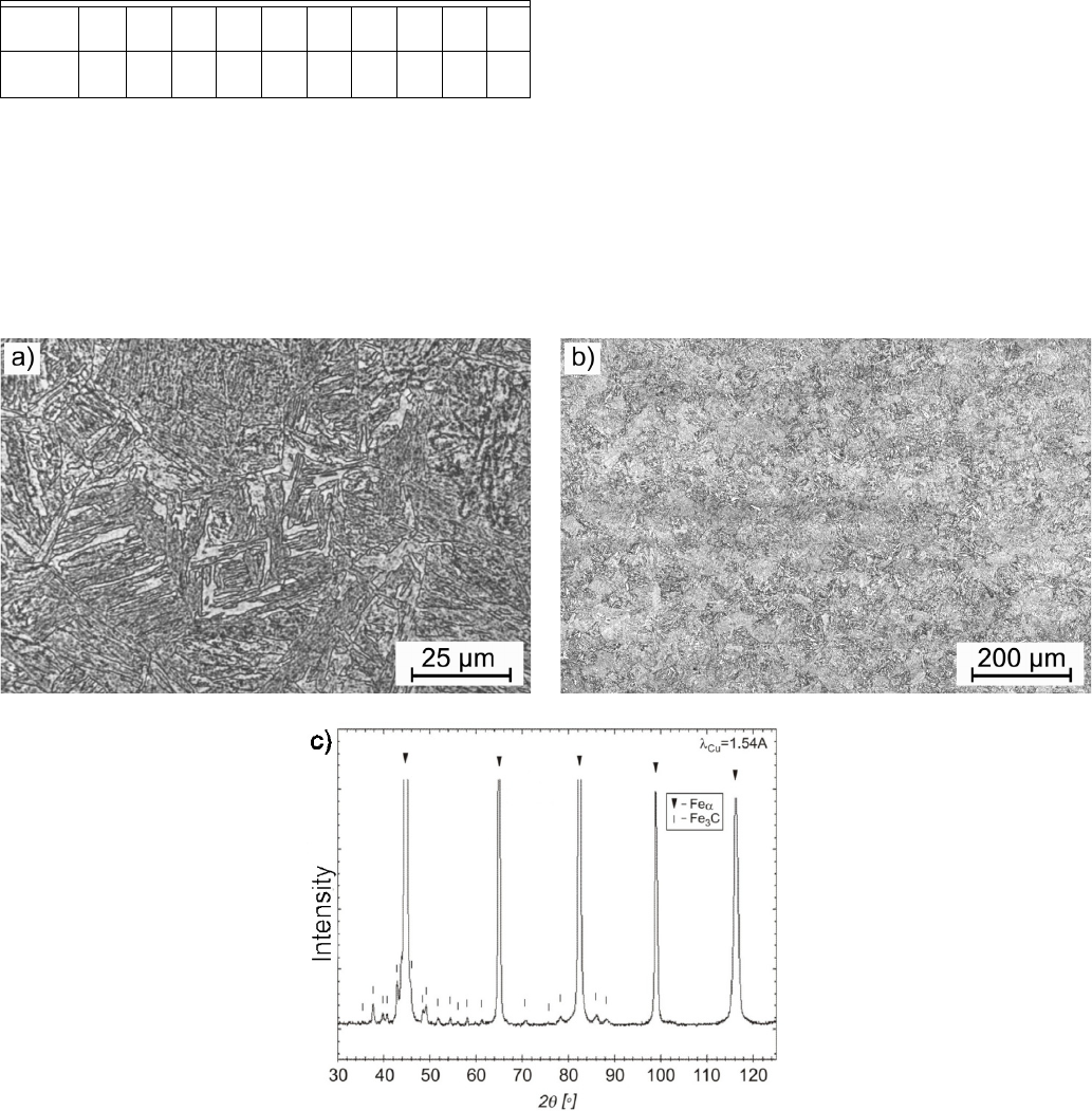
). The initial microstructure (as shown in
Fig. 1) in as-received condition consisted of bainite-martensite
mixture with fine particles identified as cementite (Fig. 1c).
TABLE 1
Chemical composition of steel 300M used in the study
Alloying
element
CMnSiCrMoNi S P VFe
Content,
wg. %
0,38 0,6 1,45 0,7 0,29 1,65 0,01 0,01 0,05 bal.
2.2. Flow behaviour analysis
Flow curves were elaborated for the needs of description
of the rheological behaviour of steel 300M in numerical mod-
eling with finite element method (FEM) and construction of
the processing maps. The flow curves (set together on graphs
in Fig. 2.) were derived from compression tests conducted on
testing machine Gleeble 3800. FEM modeling of the upset
forging process was carried out with code QForm3D with as-
sumption of rigid-plastic model of deformed body and Levanov
friction model, applying coupled thermal-mechanical analysis
for solution of actual temperature, strain and stresses fields in
the points of interest.
2.3. Dynamic behaviour modeling
Hot deformation characteristics were established based on
uniaxial compression tests. Compression tests were carried out
in a wide range of temperatures (800-1200°C) and strain rates
(0,01-100 s
–1
). Obtained stress-strain curves were a basis for
correlation between Zener-Hollomon parameter and flow stress,
for which the constitutive equation proposed by Sellars was
used. Having estimatied of activation energy (Q
śr
= kJ· mol
–1
),
coefficient of energy dissipation η % and processing maps
were constructed. The maps indicated four windows of the
metal flow instability. As an experimental verification of the
theoretical analysis of the flow behaviour, experimental tests
Fig. 1. Characterization of the material used in the study: a-b) microstructure in as-received condition, c) identification of the precipitates with
x-ray diffraction

2249
were conducted with screw press and hammer forging in lower
temperature range of the work regime, 800-850°C. Obtained
samples exhibited metallurgical soundness, however, indicated
nonuniformity of deformation reflected by variations microstruc-
ture resultant from selective deformation and inhomogeneous
pattern of recrystallized grains. As suggested by the calculated
processing windows, increasing the work temperature resulted
in improvement in microstructure uniformity, reflected by me-
chanical properties in as-forged condition.
Workability analysis carried out for selection of the most
favourable forging conditions for steel 300M was based on
Dynamic Material Modelling method [5-7,9,10] with the use of
Prasad approach [5,6,11-13]. In the Dynamic Material Model
(DMM) the unit power (P) absorbed – by the material during
plastic working is expressed in the following way [5-7,9,10]:
00
p
PGJdd
HV
VH V H HV
³³
(7)
where G – dissipator content (represents the power dissipated
by plastic work, which is converted into heat), J – dissipator co-
content, a component which represents power dissipation into
microstructural transformations, such as dynamic recrystalliza-
tion, dynamic recovery and/or grain growth. The value of this
component can be calculated from the formula:
0
1
m
Jd
m
V
VH
HV
³
(8)
where: ε constant true strain value, σ – the flow stress, MPa,
ε
·
the strain rate, s
–1
, m parameter of the strain rate sensitivity of
flow stress, usually referred to as
,
log
log
T
m
H
V
H
§·
w
¨¸
w
©¹
(9)
The efficiency of power dissipation (η), as a measure of the
ability to undergo plastic deformation, was estimated from the
equation proposed by Prasad
max
2
1
Jm
Jm
K
(10)
where J : dissipator co-content
max
22
P
JJ
, – or m = 1,
m – coefficient describing sensitivity to strain rate [5,6]. With
the use of calculated value of η(%), maps of dissipation power
efficiency were built. The criterion for identification of the
metal flow instability during hot deformation put forward by
Ziegler [14] is
log
1
log
m
m
m
[H
H
§·
w
¨¸
©¹
w
(11)
With the assumption that the parameter ξ ≤ 0 is reached,
microstructural instability of the metal flow is concluded,
reflected by occurrence of e.g. adiabatic shearing bands, strain-
induced dynamic ageing, flow turbulences. Process instability
is a complex notion referring to a given temperature and strain
rate, which can be referred to as the conditions under which the
deformation takes place. Parameter ξ forms a sort of warning
while designing the process for a new material, whereas any
changes in the value of the parameter enable the construction
of an instability map.
The processing mp is made up by superposition of power
dissipation effectiveness map (η(%) elucidated with isoclines)
with the metal flow instability parameter (ξ)).
2.2. Forging test conditions
Physical verification was carried out by means of physical
modelling. The experimental results were to confirm the appli-
cability of the processing maps in design of the forging process
in aspects of producing sound part and proper microstructure,
Fig. 2. Stress-strain characteristics derived from uni-axial compression tests on Gleeble 3800 for: a) constant strain rate 10 1/s, b) constant tem-
perature 1100°C
2250
which is indirectly indicated by instability and energy dissipation
parameters, respectively. For assessment of final properties of
the as-forged steel 300M microstructure was analysed and tensile
properties established.
The forging tests were conducted with screw press and
hammer forging in hot forging (1000°C) and within the range
of the warm work temperature range, 800-850°C.
The rolled bar was cut on sections of length resultant
from the volume the forged part including flash and subject to
homogenization annealing in accordance with temperature re-
gime common for that grade [3] and heated up/cooled down to
forge temperature. Deformation took place after soaking at the
deformation temperature for 20 minutes. Forging experiment was
carried out on a screw press of maximum flywheel energy 16 kJ
and ram starting speed 0.7 m/s. Based on dilatometric curves
characterized for this heat [8] transformation points were deter-
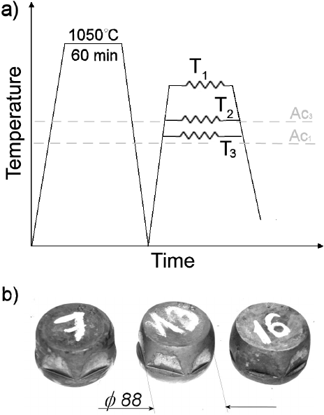
mined, which allowed selection of forging temperatures. Three
different deformation temperatures were used, so as to represent
three unique temperature ranges: 1) 1000°C – hot-work range,
2) 850°C – lower range of hot-forging regime, and 3) 800°C –
intercritical range between A
c3
and A
c1
, as shown in Fig. 3a)
.
Pyrometer measurement was maintained for tracing the
actual forging temperature and calibrated with established emis-
sivity characteristics to ensure accuracy [15] as well as thermo-
couple measurement during soaking, forging and cooling, with
probe located in the core of the billet at the half of the height.
From the forged samples (Fig. 3b) specimens for metallographic
work and tensile testing were extracted, in direction suggested
by ultrasonic detection so as to omit post-probe discontinuities.
Fig. 3. The experimental specimens: a) plan of the tests, b) the forged
samples
3. Results
3.1. Workability estimation with processing maps
In assessment of warm-range forgeability of steel 300M,
significant sensitivity of the power dissipation and stability of
deformation in temperature 800÷900°C can be concluded. It
means that there is a linear relation between instant values of
the strain rate hardening exponent and temperature increment.
The processing maps constructed for the Cr-Mo steel 300M
(Fig. 4) indicate the areas of metal flow instability (dark fields),
for which ξ ≤ 0, and elucidated with isoclines levels of power
dissipation, η%. For the considered range of strain ε = 0.1, 0.3,
0.5, 0.7 and 0.9 equivalent domains (processing windows of
strain rate promoting highest efficiency of plastic deformation
at temperature concerned) can be determined. They are the basis
for definition of suggested values of these parameter for forging
process, which for warm forging ranges between ε
·
= 1÷10 s
–1
and for hot forging ε
·
= 0.03÷1 s
–1
, providing driving force for
dynamic recovery and recrystallization with satisfactory stability
of the deformation process, without local energy accumulation.
According to thus constructed maps, proper stability of the
forging process conditions is expected within 825÷900°C and
1000÷1170°C. For strain degree 0.9 two processing windows
can be distinguished: rectangular field featuring efficiency
η = 19-24% for temperature 825÷900°C and strain rate ranging
1÷10 s
–1
. The available window corresponds to forging small or
flat geometries on screw or hydraulic press.
Isoclines of parameter η% attain density and gradient con-
forming to increasing temperature, and their contours suggest
uniformity and the metal flow stability during forging stages.
The other processing window found for temperatures
1000÷1170°C and strain rate 0.03÷1 s
–1
is contained in the range
of isoclines efficiency η = 22-32%. The isoclines of the power
dissipation parameter feature a slight increments from eachother
occasionally bulging towards higher speeds at 1000÷1100°C
switching to higher density within 1100÷1170°C. It may mean
that the plastic flow resistance is function of ε, ε
·
, T, and the
behaviour is representative of the response of the material hot
forged on slow action hydraulic presses.
When reaching 0.9 two areas of flow instability can be
found. The first one is located within the range 800-825°C above
the strain rate of 56 s
–1
. Adiabatic shear bands and/or microstruc-
tural defects may occur in that area. The coordinates of the other
one are 800÷875°C and 0.01-0.25 s
–1
. As far as the intermediate
amount of strain, ε = 0.1-0.7 is concerned, the areas extend and
move towards lower Zener-Hollomon values.
3.2. Properties of the forged samples
Hot forged specimens after air cooling produced typical
microstructure for both of the analysed regions. Beneath 40 μm
deoxitated case of ferrite, the undersurface regions grade 300M
exhibits martensitic-bainitic structure with the laths reaching

2251
Fig. 4. Processing maps in function of temperature and strain rate with consideration of instability areas constructed for steel 300M with Prasad
approach for true strain: a) 0.1, b) 0.3, c) 0.5, d) 0.7, e) 0.9

2252
12 μm in length, which come down to average 6-7 μm in the
bulk. In the warm forged specimens, the grains are outlined with
proeutectoid ferrite which at lower temperature appears mixed
with pearlitic and/or bainitic colonies and features subgrain for-
mation in the ferrite phase. In the interior of the bulk specimens
the microstructure consists of pearlitic-ferritic microstructure of
recrystallized grains of 9 ASTM grain size (Fig. 5b).
It is obvious that the phase composition is related to hard-
enability and location concerned, whereas the grain structure
can tell more about dynamic behaviour. In both cases the grain
structure is similar, although no distinct flow localization was
observed, the grain size was not uniformly distributed, in the
(Fig. 5b,c,e,f) areas of 9 ASTM in vicinity of 6-7 ASTM can be
seen. This tendency is more distinct in the intermediate forging
regime, where preferential flow localization in the unstable
region of austenitic transformation took place in the aftermath
of heat generation. In the both forging ranges, hot and warm,
the forged material indicated relatively similar flow behaviour,
resulting in sound forgings, wherein no separation or cracking
occurred. In many studies concerning workability assessment
with processing maps, the microstructure is quenched practiced
so as to freeze the as-forged condition. In this work the idea was
Fig. 5. Microstructure of analysed steel 300M forged at: a), d) 800°C; b), e) 850°C and c), f) 1000°C in the undersurface region (a-c) and in the
axis (d-f)

2253
to reflect the material behaviour in a state typical of air-cooled
condition, representative of good hardenability steels. Thus
the workability and microstructure evolution can be evaluated
through the obtained mechanical properties, shown in Table 2.
From the mechanical properties and microstructure one can con-
clude the workability was satisfactory in the light of providing
amount of deformation required for high strength and fair ductil-
ity, typical of quenched condition, in reference to related studies
[16,17]. The microstructure is even throughout the cross-section
and the final features depend rather on the cooling conditions
and related to amount of martensite and rest austenite, uniform-
ity of strength properties can be assumed from the standpoint of
former austenite grain size after forging [18].
TABLE 2
Tensile properties of steel 300M in as-forged condition
Forging,
tempera-
ture, [°C]
TYS,
MPa
UTS,
MPa
Elon-
gation,
%
Area re-
duction,
%
V-notch
Impact
strength,
J/cm
2
Hardness
HRC
1000 1505 2231 5,8 22 43,3 57
850 1143 1885 6,6 21 34,0 55
800 855 1634 7,8 12 33,2 53
Numerically estimated values of strain and strain rate
(Fig. 5f – grey line) observed in the axis are linked with maps in
(Fig. 5c-d). The processing window locates between two instabil-
ity areas. From the standpoint of workability that provides are
relatively safe processing conditions, however, there is a local
minimum of energy dissipation found for strain rate ranging
from 10
0
to 10
1
s
–1
, which means that under these conditions the
material is at closest to viscosity. Bigger failure hazard could be
expected in the location which lies in the near-surface region of
hexagonal face (Point 2 – black line in Fig. 5f), where strain rate
reaches double values or in the flash area, where it grows up to
90 s
–1
. However, the high strain stage of forging was preceded
by considerable deformation at moderate strain rate, enhancing
plasticity. The corresponding region on high-strain processing
maps (Fig. 5d-e) is closer to the “upper” instability area, which
here is shifted to lower temperature range and the area of low
energy dissipation forms a wedge reaching 1000°C. Yet the hot
forging was still beyond this area, resulting in austenite grain
size comparable to those observed in the bulk.
Confronting the resulted microstructure and properties with
processing maps, it can be said the material demonstrates rela-
tively good forgeability, irrespective of the temperature regime.
Comparing the material condition between analysed locations
(Fig. 5a-c) versus (Fig. 5d-f), much lesser difference is observed
than could be expected from the values of strain and strain-rate
concentration in the axis of the specimens (Point 1 in Fig. 4f)
and the microstructure in the surface (Point 2 in Fig. 4f) and,
respectively, isoclines at corresponding strains. The surface of
the specimens was good, without signs of separation or rupture.
One may conclude that the workability of steel 300M at lower
hot forging temperature and in intercritical region is relatively
good. As indicated in strain rate and temperature plots derived
from numerical simulation, screw press, similarly to mechanical
press, offers rates of straining which locate just between two in-
stability regions which may be ascribed to hammers on one side
and hydraulic presses on the opposite, where a large instability
region persists from small to large strain levels. In addition to
increased strain rates, the area is omitted due to increasing actual
temperature by deformation heat generation.
5. Conclusions
The presented study allowed the analysis of the flow be-
haviour of ultra-high strength steel 300M with use of dynamic
material modelling and elaboration of processing maps. The
main conclusions it allowed to formulate are:
1. Definition of sensitive areas of energy dissipation into solid
state dynamic transformations and regions of metal flow
instability during forging indicated „safe” forging regime
of temperature and selection of equipment for realization
in selected temperature range. In this respect screw and
mechanical presses provide suitable strain rate for average
upset-forged geometry.
2. Workability indices defined by instability coefficient and
energy dissipation coefficient in the function of strain rate
versus working temperature suggest relatively good work-
ability of the material both in hot and warm forging tem-
perature. The processing window in which observed strain
rates, 20÷90 s
–1
are found, exhibits maximum viscosity up
to 1000°C temperature, which means the least energy is
dissipated into dynamic phenomena which could contribute
to the metal flow instability. Thus, warm forging regime
offers good technological conditions for forging on a fast
action press, preventing from detrimental surface effects,
such as excessive scale formation or decarbonization.
Acknowledgements
Financial assistance of MNiSzW within the statutory funds in the frame -
work of agreement 11.11.110.292 is acknowledged.
Special thanks are expressed to Krzysztof Kłaput of forge plant Śrubena
Unia S.A. for facilitating the industrial forging equipment and to Tadeusz
Skowronek, Piotr Bała, Marek Paćko and Joanna Kowalska for assistance
in material characterization.
REFERENCES
[1] T.E. Pistochini, M.R. Hill, 34, 521-533 (2011).
[2] T.J. McCaffrey, ASM Handbook 01, Properties and Selection:
Irons, Steels, and High-Performance Alloys. ASM International,
Materials Park,Ohio, 1990.
[3] S.L.Semiatin, ASM Handbook 14, Forging and Forming, ASM
International, 1996.
2254
[4] J. Luo, M.Q. Li, Y.G. Liu, H.M. Sun, Materials Science & Engi-
neering A 534, 314-322 (2012).
[5] Y.V.R.K. Prasad, S.Sasidhara (ed.), Hot working guide: A com-
pendium of processing maps, ASM International, 1997.
[6] G.E. Dieter, H.A.Kuhn, S.L. Semiatin, Handbook of Workability
and Process Design, ASM International, 2003.
[7] N.S.V.S. Murty, N.B. Rao, B.P. Kashyap, Journal of Materials
Processing Technology 166, 268-278 (2005).
[8] S. Bednarek, J. Krawczyk, P. Bała, A. Łukaszek-Sołek, in J. Ku-
siak, J. Majta, D. Szeliga (Eds.),Weinheim: Wiley-VCH Verlag-
GmbH&Co. KGaA, cop. 2012, Steel Research International; spec.
ed., 179-182.
[9] Y.V.R.K. Prasad, T. Seshacharyulu, International Materials Re-
views 43, 243-258 (1998).
[10] Y.V.R.K. Prasad, Journal of Materials Engineering and Perfor-
mance 12, 638-644 (2003).
[11] A. Łukaszek-Sołek, Acta Metallurgica Sinica (English Letters)
28, 122-131 (2015).
[12] A. Łukaszek-Sołek, J. Krawczyk, Materials and Design 65, 165-
173 (2015).
[13] A. Łukaszek-Sołek, P. Skubisz, Polska Metalurgia w latach 2011-
2014, Komitet Metalurgii PAN 669-683 (2014).
[14] E. Pu, W. Zheng, J. Xiang, Z. Song, J. Li, Materials Science and
Engineering A 598, 174-182 (2014).
[15] P. Skubisz, P .Micek, J. Sińczak, M. Tumidajewicz, Solid State
Phenomena 177, 76-83 (2011).
[16] Y. Tomita, Materials Science and Technology 11, 335-339 (1995).
[17] R. Zhao, T. Liu, X. Zhao, Materials Science Forum 749, 287-293
(2013).
[18] P. Skubisz, Ł. Lisiecki, Key Engineering Materials 611-612, 167-
172 (2014).
